

Page 1
40G/100G MULTISERVICE TEST MODULE
FTB/IQS-85100G
Packet Blazer
User Guide
Page 2

Copyright © 2012–2015 EXFO Inc. All rights reserved. No part of this
publication may be reproduced, stored in a retrieval system or transmitted
in any form, be it electronically, mechanically, or by any other means such
as photocopying, recording or otherwise, without the prior written
permission of EXFO Inc. (EXFO).
Information provided by EXFO is believed to be accurate and reliable.
However, no responsibility is assumed by EXFO for its use nor for any
infringements of patents or other rights of third parties that may result from
its use. No license is granted by implication or otherwise under any patent
rights of EXFO.
EXFO’s Commerce And Government Entities (CAGE) code under the North
Atlantic Treaty Organization (NATO) is 0L8C3.
The information contained in this publication is subject to change without
notice.
Trademarks
EXFO’s trademarks have been identified as such. However, the presence
or absence of such identification does not affect the legal status of any
trademark.
Units of Measurement
Units of measurement in this publication conform to SI standards and
practices.
March 12, 2015
Document version: 8.0.0.1
ii FTB/IQS-85100G
Page 3

Certification Information
Certification Information
North America Regulatory Statement
This unit was certified by an agency approved in both Canada and the
United States of America. It has been evaluated according to applicable
North American approved standards for product safety for use in Canada
and the United States.
Electronic test and measurement equipment is exempt from FCC part 15,
subpart B compliance in the United States of America and from ICES-003
compliance in Canada. However, EXFO Inc. makes reasonable efforts to
ensure compliance to the applicable standards.
The limits set by these standards are designed to provide reasonable
protection against harmful interference when the equipment is operated in
a commercial environment. This equipment generates, uses, and can
radiate radio frequency energy and, if not installed and used in accordance
with the user guide, may cause harmful interference to radio
communications. Operation of this equipment in a residential area is likely
to cause harmful interference in which case the user will be required to
correct the interference at his own expense.
Modifications not expressly approved by the manufacturer could void the
user's authority to operate the equipment.
Packet Blazer iii
Page 4

Certification Information
European Community Declaration of Conformity
Warning: This is a class A product. In a domestic environment, this product
may cause radio interference in which case the user may be required to
take adequate measures.
An electronic version of the declaration of conformity for your product is
available on our website at www.exfo.com. Refer to the product’s page on
the Web site for details.
Laser
This product complies with 21 CFR 1040.10 except for deviations pursuant
to Laser Notice No. 50, dated June 24, 2007 and with IEC/EN 60825-1.
iv FTB/IQS-85100G
Page 5

Contents
Certification Information .......................................................................................................iii
1 Introducing the 40G/100G Multiservice Test Module ................................. 1
Features ..................................................................................................................................1
Conventions ............................................................................................................................2
2 Safety Information ....................................................................................... 3
Additional Laser Safety Information .......................................................................................4
Installation Instruction Warnings ............................................................................................5
3 Getting Started ............................................................................................ 7
Inserting and Removing Test Modules ....................................................................................7
Turning On the Unit ................................................................................................................7
Starting the Module Application .............................................................................................7
4 Physical Interfaces and LEDs ....................................................................... 9
Supported Rates ..................................................................................................................11
CFP Interface ........................................................................................................................12
Fibre Cables Connection ......................................................................................................14
EXT CLK ...............................................................................................................................15
Clock Out .............................................................................................................................15
LEDs ......................................................................................................................................15
5 Graphical User Interface Overview ............................................................ 17
Main Application Window ...................................................................................................17
Main Window .......................................................................................................................17
Status Bar ............................................................................................................................18
Title Bar ...............................................................................................................................19
Test Control .........................................................................................................................19
Test Menu ............................................................................................................................20
Application Buttons .............................................................................................................20
Keyboard Usage ...................................................................................................................22
Packet Blazer v
Page 6

6 Test Setup - Test Applications ...................................................................25
OTN BERT ..............................................................................................................................26
OTN-SONET/SDH BERT ..........................................................................................................28
SONET/SDH BERT ..................................................................................................................31
EtherSAM (Y.1564) ...............................................................................................................33
RFC 2544 ..............................................................................................................................34
EtherBERT .............................................................................................................................35
Traffic Gen & Mon ...............................................................................................................36
Smart Loopback ....................................................................................................................37
7 Selecting and Starting a Test .....................................................................39
Transport Test Applications ...................................................................................................39
Ethernet Test Applications ....................................................................................................41
vi FTB/IQS-85100G
Page 7

8 Test Setup - Test Configurator, Timer, and System .................................. 43
Test Configurator Overview ..................................................................................................45
Modify Structure Button ......................................................................................................49
BERT and Unframed BERT .....................................................................................................61
CFP/CFP2 ..............................................................................................................................66
Clock .....................................................................................................................................67
EtherBERT and Unframed BERT ............................................................................................72
EtherSAM - Burst .................................................................................................................77
EtherSAM - Global ...............................................................................................................79
EtherSAM - Ramp ................................................................................................................83
Frequency .............................................................................................................................85
FTFL/PT ..................................................................................................................................87
GFP-F/GFP-T ..........................................................................................................................90
Interface (Ethernet) ..............................................................................................................91
Labels ..................................................................................................................................96
MAC/IP/UDP .........................................................................................................................97
Network .............................................................................................................................109
RFC 2544 - Global ..............................................................................................................113
RFC 2544 - Subtests ...........................................................................................................116
Services - Global ................................................................................................................123
Services - Profile .................................................................................................................126
Signal (Transport) ..............................................................................................................133
Signal - Signal Configuration (OTN) ....................................................................................138
Signal - Signal Configuration (SONET/SDH) ........................................................................142
Smart Loopback .................................................................................................................145
Streams - Global ................................................................................................................146
Streams - Profile ................................................................................................................148
System ................................................................................................................................156
Timer ..................................................................................................................................157
Traces (OTN) .......................................................................................................................159
Traces (SONET/SDH) ...........................................................................................................162
Packet Blazer vii
Page 8

9 Test Results ................................................................................................165
Alarms/Errors Overview .......................................................................................................167
Alarms/Errors .....................................................................................................................169
FTFL/PT ................................................................................................................................206
GFP-F/GFP-T ........................................................................................................................208
Graph (RFC 2544) ...............................................................................................................211
Labels ................................................................................................................................212
Logger ...............................................................................................................................213
OTL-SDT ..............................................................................................................................215
Performance Monitoring ....................................................................................................217
Service Configuration - Burst .............................................................................................222
Service Configuration - Ramp ............................................................................................223
Service Performance ..........................................................................................................225
Streams - Frame Loss / Out-of-Sequence ............................................................................227
Streams - Jitter ...................................................................................................................227
Streams - Latency ..............................................................................................................228
Streams - Throughput ........................................................................................................229
Summary ...........................................................................................................................230
Summary (EtherSAM) ........................................................................................................234
Summary (RFC 2544) .........................................................................................................237
Summary (Traffic Gen & Mon) ...........................................................................................240
Traces - OTN .......................................................................................................................242
Traces - SONET/SDH ...........................................................................................................244
Traffic - Ethernet ................................................................................................................245
Traffic - Flow Control .........................................................................................................247
Traffic - Graph ....................................................................................................................249
10 Test Functions ...........................................................................................251
40/100G Advanced - CFP/CFP2 Control ..............................................................................253
40/100G Advanced - Lanes Mapping & Skew ....................................................................256
40/100G Advanced - Pre-Emphasis ....................................................................................261
APS ....................................................................................................................................263
Client Offset ......................................................................................................................266
Filters .................................................................................................................................269
Packet Capture ...................................................................................................................273
GMP ..................................................................................................................................279
OH - GFP-F/GFP-T ...............................................................................................................280
OH - OTN ............................................................................................................................285
OH - SONET/SDH ................................................................................................................291
Ping & Trace Route ..............................................................................................................300
Pointer Adjustment ............................................................................................................305
RTD .....................................................................................................................................307
viii FTB/IQS-85100G
Page 9

11 Test Control .............................................................................................. 311
Discover Remote Button ....................................................................................................312
Inject Button .......................................................................................................................315
Laser Button .......................................................................................................................315
Report Button ....................................................................................................................316
Reset Button .......................................................................................................................320
Save/Load Button ...............................................................................................................321
Start/Stop|TX Button ..........................................................................................................327
12 Power Failure Recovery ............................................................................ 329
When Using the Test Timer .................................................................................................331
13 Suspend and Resume ............................................................................... 333
Suspend Mode ....................................................................................................................333
Resume Operation ..............................................................................................................334
14 Maintenance ............................................................................................. 335
Cleaning LC/SC/MPO-24 Connectors ...................................................................................336
Recalibrating the Unit .........................................................................................................337
Recycling and Disposal (Applies to European Union Only) ..................................................338
15 Troubleshooting ....................................................................................... 339
Solving Common Problems .................................................................................................339
Contacting the Technical Support Group ............................................................................340
Transportation ....................................................................................................................340
16 Warranty ................................................................................................... 341
General Information ...........................................................................................................341
Liability ...............................................................................................................................342
Exclusions ...........................................................................................................................342
Certification ........................................................................................................................342
Service and Repairs .............................................................................................................343
EXFO Service Centers Worldwide ........................................................................................344
A Specifications ........................................................................................... 345
General Specifications ........................................................................................................345
40G/100G Pluggable Transceivers (CFP) ..............................................................................346
100G Pluggable Transceivers (CFP2) ...................................................................................347
Additional Features on High-Speed Interface .....................................................................348
Synchronization Interface ..................................................................................................348
REF-OUT Interfaces ............................................................................................................349
Packet Blazer ix
Page 10

B Glossary .....................................................................................................351
Acronym List .......................................................................................................................351
10G Ethernet Client ............................................................................................................361
G.709 Optical Transport Network (OTN) ............................................................................364
Generic Framing Procedure (GFP) ......................................................................................381
SONET/SDH .........................................................................................................................393
VLAN ID and Priority ...........................................................................................................402
C Remote ToolBox ......................................................................................403
Overview .............................................................................................................................403
Remote ToolBox Installation ................................................................................................405
Starting and Using the Remote ToolBox Application ..........................................................406
Applications for... ...............................................................................................................408
Index ...............................................................................................................409
x FTB/IQS-85100G
Page 11

1 Introducing the 40G/100G
Multiservice Test Module
Fully integrated layer 1/2/3/4 performance assessment of 40 Gbit/s and
100 Gbit/s Ethernet, SONET/SDH, and Optical Transport Network (OTN)
equipment and network services.
Features
40G/100G Ethernet fully compliant with IEEE 802.3ba standard and
OTU3/OTU4 as per ITU-T G.709 and OC-768/STM-256 testing
capabilities—all in a single module
OTU4/OTU3 and OTU3e1/e2 with forward error correction (FEC) and
optical transport layer (OTL) testing capabilities as software options
100G/40G Ethernet mapping over OTN and OTU4/OTU3 single and
multistage multiplexing capabilities for transponder and muxponders
testing
100G/40G IP traffic at 100% transmission with full Ethernet statistics,
packet capture and advanced traffic filtering capabilities
RFC 2544 including throughput, back-to-back, latency and frame loss
measurements with five distinct Smart Loopback modes
Fully integrated testing capabilities for assessing CFP MSA optical
modules with full MDIO access
Physical-layer performance assessment: PCS into CAUI/XLAUI and
logical into physical mappings, skew testing and advanced signal
conditioning capabilities
Single instrument for lab testing and field deployments with Ethernet
and OTN integrated features, remote management, battery operation,
pre-defined user configurations and complete automation capabilities
Packet Blazer 1
Page 12

Introducing the 40G/100G Multiservice Test Module
Conventions
Conventions
Before using the product described in this guide, you should understand
the following conventions:
WARNING
Indicates a potentially hazardous situation which, if not avoided,
could result in death or serious injury. Do not proceed unless you
understand and meet the required conditions.
CAUTION
Indicates a potentially hazardous situation which, if not avoided,
may result in minor or moderate injury. Do not proceed unless you
understand and meet the required conditions.
CAUTION
Indicates a potentially hazardous situation which, if not avoided,
may result in component damage. Do not proceed unless you
understand and meet the required conditions.
IMPORTANT
Refers to information about this product you should not overlook.
2 FTB/IQS-85100G
Page 13

2 Safety Information
WARNING
Do not install or terminate fibers while a light source is active.
Never look directly into a live fiber and ensure that your eyes are
protected at all times.
WARNING
The use of controls, adjustments and procedures, namely for
operation and maintenance, other than those specified herein may
result in hazardous radiation exposure or impair the protection
provided by this unit.
IMPORTANT
When you see the following symbol on your unit , make sure
that you refer to the instructions provided in your user
documentation. Ensure that you understand and meet the required
conditions before using your product.
IMPORTANT
Other safety instructions relevant for your product are located
throughout this documentation, depending on the action to
perform. Make sure to read them carefully when they apply to your
situation.
Packet Blazer 3
Page 14
Safety Information
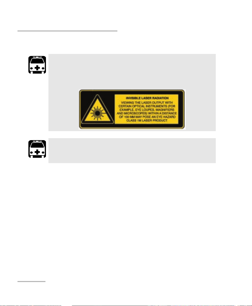
Additional Laser Safety Information
Additional Laser Safety Information
This product may employ a Class 1M laser pluggable transceiver.
The laser classification is reproduced on the pluggable transceiver
or in its documentation.
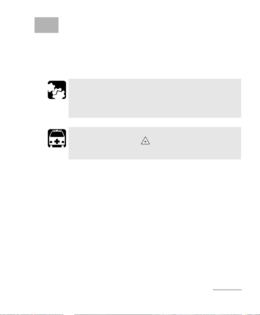
When the LASER LED is on or flashing, the FTB/IQS-85100G is
transmitting an optical signal on the CFP, or CFP2 transceiver ports.
WARNING
WARNING
Note: Refer to the platform’s user guide for additional test equipment safety
information and ratings.
4 FTB/IQS-85100G
Page 15

Safety Information
Installation Instruction Warnings
Installation Instruction Warnings
CAUTION
For IQS platforms,
this unit is for indoor use only.
keep all ventilation openings clear and unobstructed.
CAUTION
When you use the unit outdoors, ensure that it is protected from
liquids, dust, direct sunlight, precipitation, and full wind pressure.
CAUTION
Unless otherwise specified, all electrical interfaces are SELV (Safety
Extra Low Voltage) circuitry for intra-building use only.
CAUTION
No user serviceable parts are contained inside. Contact the
manufacturer regarding service of this equipment.
IMPORTANT
All wiring and installation must be in accordance with local building
and electrical codes acceptable to the authorities in the countries
where the equipment is installed and used.
Packet Blazer 5
Page 16

Safety Information
Installation Instruction Warnings
Electrostatic Discharge (ESD) Sensitive Equipment:
Plug-in modules can be damaged by static electrical discharge. To
minimize the risk of damage, dissipate static electricity by touching
a grounded unpainted metal object
before removing, inserting, or handling the module.
before connecting or disconnecting cables to/from the module.
before inserting or removing CFP, or CFP2 transceiver to/from the
module.
CAUTION
6 FTB/IQS-85100G
Page 17
3 Getting Started
If the FTB/IQS-85100G Packet Blazer has been purchased at the same time
as the platform, the FTB/IQS-85100G module is pre-installed with the
appropriate software version.
Inserting and Removing Test Modules
CAUTION
Never insert or remove a module while the platform and its
expansion units (IQS-600) are turned on. This will result in
immediate and irreparable damage to both the module and
platform.
WARNING
When the laser safety light ( ) is flashing on the platform, at
least one of your modules is emitting an optical signal. Please check
all modules, as it might not be the one you are currently using.
Note: Refer to the platform user guide for more information on how to insert a
module into the platform or to remove a module from the platform.
Turning On the Unit
Turn on the platform. Refer to the platform platform user guide for more
information.
Starting the Module Application
The module can be configured and controlled by starting
the FTB/IQS-85100G Packet Blazer application.
From To olB ox (FTB-500) or IQS Manager (IQS-600), tap the
FTB/IQS-85100G Packet Blazer button to start the application.
Packet Blazer 7
Page 18

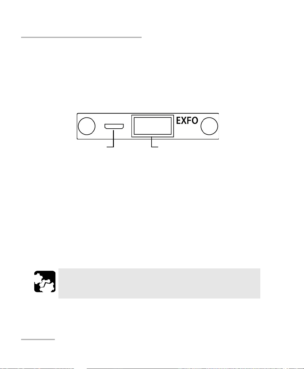
Page 19
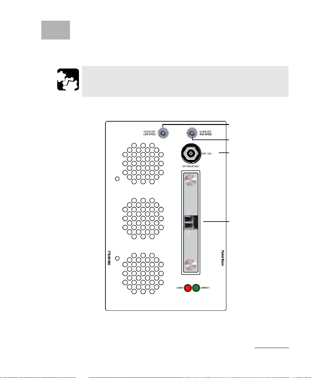
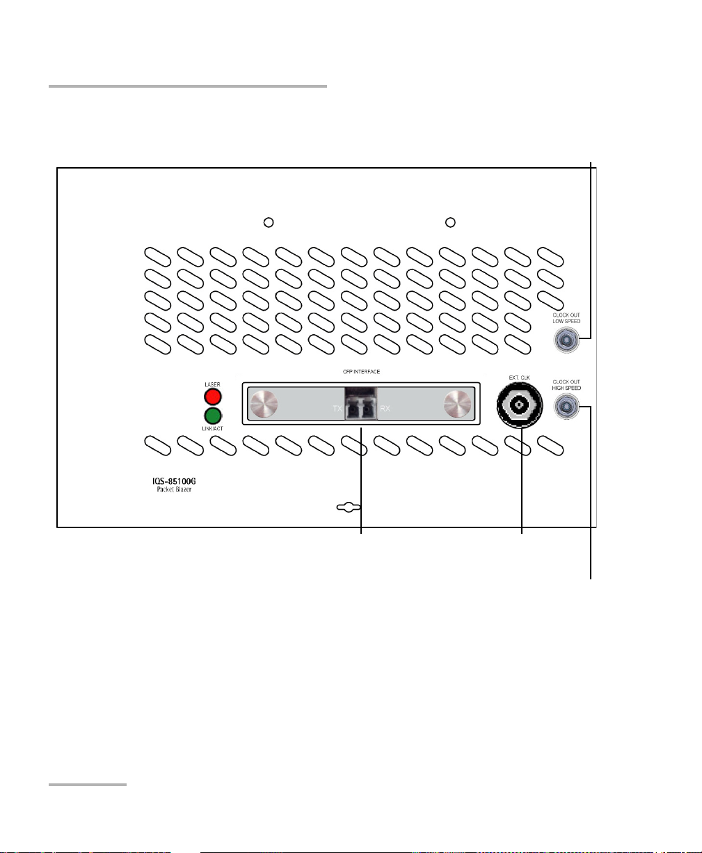
4 Physical Interfaces and LEDs
CFP Interface1
External Clock
Clock Out Low Speed
Clock Out High Speed
1. Laser radiation emitted from this port when LASER LED is on.
This section describes all connectors (ports) and LEDs available on the
FTB/IQS-85100G module.
CAUTION
To prevent exceeding the maximum input/output power level,
please refer to the Specifications on page 345.
FTB-85100G
Packet Blazer 9
Page 20
Physical Interfaces and LEDs
CFP Interface1 External Clock
Clock Out Low Speed
Clock Out High Speed
1. Laser radiation emitted from this port when LASER LED is on.
IQS-85100G
10 FTB/IQS-85100G
Page 21

Physical Interfaces and LEDs
Supported Rates
The following table shows the list of available ports as well as a description
and signals supported.
Port Labelled Description Supported Signal(s)
CFP Optical IN/OUT port CFP
transceiver.
CLOCK OUT LOW SPEED
CLOCK OUT HIGH SPEED
EXT CLK Electrical port SMB for external
Electrical port SMA for eye
diagram clock signal generation.
clock synchronization.
Ethernet 40/100 Gbit/s
OC-768/STM-256, OTU4, OTU3e2, OTU3e1,
OTU3
Refer to CFP/CFP2 Reference Clock (MHz) on
page 253 for more information.
DS1 (1.5M), E1 (2M), 2MHz
Supported Rates
Packet Blazer 11
Page 22

Physical Interfaces and LEDs
CFP Interface
CFP Interface
The FTB/IQS-85100G provides a CFP interface slot that can be used with a
CFP transceiver an EXFO’s CFP to CFP2 adapter module or an EXFO’s CFP
to CXP adapter module.
CAUTION
Before inserting an optical module into the CFP interface slot,
inspect the slot to make sure nothing is inside.
Note: Do not replace transceiver while the test is running to avoid distorting
results. First stop the test, replace the transceiver, select the connector type
(refer to Modify Structure Button on page 49), and then restart the test.
Note: To ensure proper optical module detection/validation, make sure that the
CFP screws are fully secured.
12 FTB/IQS-85100G
Page 23

Physical Interfaces and LEDs
CFP Interface
CFP Transceiver
Note: Use only EXFO supported transceivers. Refer to the 40G/100G Pluggable
Transceivers (CFP) on page 346 for the list of supported transceivers. Using
non-supported transceivers can affect the performance and accuracy of the
test.
WARNING
This product may employ a Class 1 or Class 1M laser transceiver.
EXFO CFP-to-CFP2 Adapter
The EXFO CFP-to-CFP2 adapter (FTB-85970) offers 100G testing
capabilities using CFP2 transceivers.
Note: Use only EXFO supported CFP2 transceivers. Refer to 100G Pluggable
Transceivers (CFP2) on page 347 for the list of supported CFP2 transceivers.
Using non-supported transceivers can affect the performance and accuracy
of the test.
WARNING
This product may employ a Class 1 or Class 1M laser transceiver.
Packet Blazer 13
Page 24
Physical Interfaces and LEDs
Mini HDMI CXP
EXFO’s CFP-to-CXP Adapter
Fibre Cables Connection
EXFO CFP-to-CXP Adapter
Carefully connect the supplied optical cable (32 feet) to the CXP port of the
local module and the other end to the far end module. To ensure good
signal quality, make sure that the optical cable connector is fully inserted
into the CXP connector port.
When using EXFO CFP-to-CXP Adapter on both ends, the EXFO proprietary
mini HDMI port need be used to automatically configure the CXP of the far
end module with the same parameters defined on the local module.
Connect one end of the supplied mini HDMI cable (16 feet) to the local
module and the other end to the far end module. The configuration of the
far end module will be done once the test is started on the local module
(Refer to Start/Stop|TX Button on page 327).
Fibre Cables Connection
Carefully connect optical fibre cables to the CFP/CFP2’s IN and OUT ports.
To ensure good signal quality, make sure that the optical fibre connector is
fully inserted into the optical connector port.
CAUTION
To prevent exceeding the maximum input power level please use an
attenuator when a loopback configuration is used.
14 FTB/IQS-85100G
Page 25

Physical Interfaces and LEDs
EXT CLK
The FTB/IQS-85100G provides one connector, labeled EXT CLK that can be
used either for input/output external clock DS1 (1.5M), E1 (2M), or 2MHz
synchronization signal. The connector type is BNC for coaxial 75-ohm
cable connection. An adapter cable (BNC to Bantam) is required for
Bantam connection (not supplied).
Clock Out
Low Speed: The FTB/IQS-85100G provides a connector, labelled CLOCK
OUT LOW SPEED, for eye diagram clock signal generation that can be
used by another equipment. The clock connector type is SMA. Refer to
CFP/CFP2 Reference Clock (MHz) on page 253 for more information.
High Speed: The FTB/IQS-85100G provides a connector, labelled CLOCK
OUT HIGH SPEED, for eye diagram clock signal generation that can be
used by another equipment. This clock is optional according to the CFP
MSA (Multisource Agreement) and is only available when the CFP used
provides this high speed clock signal. Refer to the CFP manufacturer and
the relevant CFP part number for more information on the high speed
clock. The clock connector type is SMA.
EXT CLK
LEDs
LASER red LED is on when the FTB/IQS-85100G is emitting an optical
laser signal.
LINK/ACT green LED is on when the link is up, off when the link is
down, and flashing when frames are transmitted and/or received.
Packet Blazer 15
Page 26

Page 27
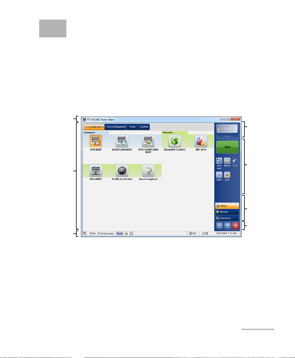
5 Graphical User Interface
Main
Window
Te st
Control
Tes t M en u
Application
Buttons
Status Bar
Global
Indicator
Title Bar
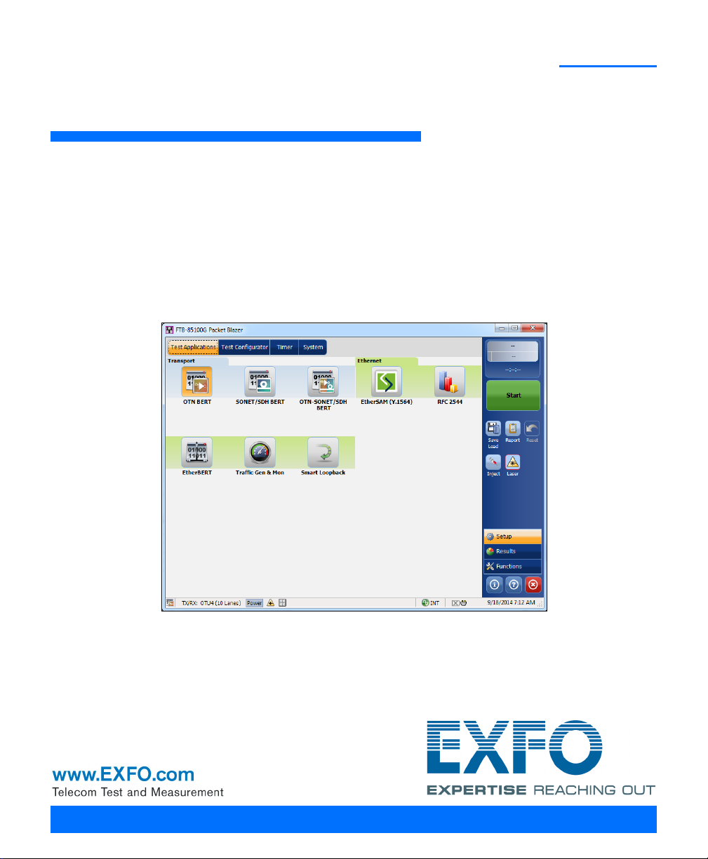
Overview
This chapter describes the FTB/IQS-85100G Packet Blazer graphical user
interface.
Main Application Window
The following main application window is displayed when the Packet
Blazer application is started.
Main Window
The main window allows to setup a test and to view the test status and
results.
Packet Blazer 17
Page 28
Graphical User Interface Overview
Status Bar
Status Bar
The status bar displays the following information.
Icon
and/or text
Test icon Test icon of the test. All
Interface/
Signal
LINK Green arrow: Ethernet Link up.
Power Level The received optical signal status:
The interface or signal rate: 40G, OTU3, etc. All
Red arrow: Ethernet Link down.
Green with “Power”: Power level in range
Yellow: Power level out-of-range
Red with “LOS”: Loss of signal
Red with “Power”: Power level is close to damage.
Gray: The operational range value is either not available or not supplied by
the transceiver.
Laser ON
control is not affected when turning off the laser by generating a LOS for
example. Refer to Laser Button on page 315.
The status of the received signal pattern:
Green: Pattern is synchronized.
Red: Loss of pattern.
Gray: Test is not running (EtherBERT test or EoOTN client) or the RX Pattern
Analysis check box is cleared.
A connection is established between two testing units either in Dual Test
Set (DTS) or in Loop Up mode.
Clock synchronization signal clock. The clock icon is followed by the clock
mode: INT for Internal, EXT for External, or BKP for Backplane.
Green: Clock Synchronized.
Red: Loss of clock.
Indicates a manual change in the OH bytes transmitted. Not displayed when
using the default OH values.
Remote PC connection established with the Packet Blazer. N/A
b
. The laser icon is not displayed when the laser is offa. The laser
Description
b
.
b
.
All
a
.
All
All
Tra nsp ort
EtherBERT
Ethernet
All
Tra nsp ort
Test
Application
18 FTB/IQS-85100G
Page 29
Graphical User Interface Overview
Title Bar
Icon
and/or text
Alarm/error is currently injected. Not displayed when there is no alarm/error
injection.
a. For all lanes.
b. For at least one lane.
The following status are available at the platform level.
Battery/AC icons, available on FTB platforms, indicate the battery level
and if the platform is connected to an AC power source. Refer to the
platform user guide for more information.
Date and Time indicate the current date and time.
Title Bar
The Title Bar displays the module’s slot number in brackets, the software
application name and the minimize, maximize, and close buttons.
Test Control
Description
Test
Application
Tra nsp ort ,
EtherBERT
Note: Refer to Test C o ntro l on page 311 for more information.
Packet Blazer 19
Page 30

Graphical User Interface Overview
Test M e n u
Test Menu
The test menu displays the following buttons:
Setup allows to configure the selected test. Refer to Test S et up - Tes t
Configurator, Timer, and System on page 43 for more information.
Results allows to view test results. Refer to Test Results on page 165 for
more information.
Functions allows to configure additional test functions (refer to Te st
Functions on page 251).
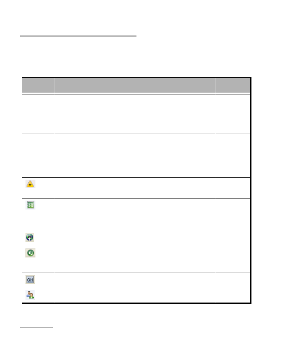
Application Buttons
Help (?) displays the help information related to the content of the
active main window. It is also possible to navigate through the
remainder of the help information.
Exit (x) closes the application.
About (i) mainly displays the product version details and technical
support information.
Module Details button displays module details such as its ID, Serial
Number, Software Product Version, etc.
View Licence Agreement button displays the details of the product
licence agreement.
20 FTB/IQS-85100G
Page 31

Graphical User Interface Overview
Application Buttons
Software Options button displays the list of software options.
Note: For information on how to install and activate software options, refer to the
platform User Guide. The module application must be restarted once a
new software option is installed in order to activate it.
Software Option Description
100GE Ethernet 100G
40GE Ethernet 40G
OTU4 Optical Transport Unit-4 (111.81 Gbit/s)
OTU3-e1-e2 Optical Transport Unit-3 Overclocked (44.571/44.583 Gbit/s)
OTU3 Optical Transport Unit-3 (43.018 Gbit/s)
40G 39.81312 Gbit/s (SONET/SDH)
ETH-CAPTURE Ethernet Frame Capture
ADV-FILTERS Advanced filtering
IPv6_40-100GE Internet Protocol Version 6 (IPv6) (40/100GE)
ODU0 OTN ODU0
ODUMUX ODU Multiplexing Payload Type 20 and 21
EoOTN Ethernet over Optical Transport Network
ODUflex OTN ODUflex
SONET Synchronous Optical Network
SDH Synchronous Digital Hierarchy
TCM Tandem Connection Monitoring STS/AU (embedded SONET/SDH up to 10G)
Packet Blazer 21
Page 32

Graphical User Interface Overview
Keyboard Usage
Keyboard Usage
The GUI pops up different keyboards to modify data. Following are the
usual keyboard keys:
Left arrow moves the cursor one position to the left.
Right arrow moves the cursor one position to the right.
Up arrow increases the value by one.
Down arrow decreases the value by one.
Del deletes the value at the cursor position.
Back deletes the value preceding the cursor position.
OK completes data entry.
Cancel closes the keyboard and discards the keyboard entry.
Previous... allows the selection of previously configured values. This
button is only available for certain fields like IP Address, MAC Address,
etc.
Note: For certain text fields, the GUI pops up or uses the platform’s on-screen
keyboard. Refer to the platform user guide for more information on how to
use it.
For full keyboard, the Back, Del, Shift, and Space bar keys have the same
functionality as a regular PC keyboard.
22 FTB/IQS-85100G
Page 33

Graphical User Interface Overview
Keyboard Usage
For multiplexing keyboard, tap on all mapped signals that have to be
added/removed to/from the test path.
A mapped signal with an orange background color is part of the test
path.
A mapped signal with a gray background color is not part of the test
path.
Packet Blazer 23
Page 34

Graphical User Interface Overview
Keyboard Usage
The Trace message keyboard allows entering alphanumerical characters
(ITU T.50) required for TTI Trace fields. Tap the Control Characters button
to access these characters.
ITU T.50 Characters
b7 to b1 Character Description b7 to b1 Character Description
000 0000 NUL Null 001 0000 DLE Data Link Escape
000 0001 SOH Start Of Heading 001 0001 DC1 Device Control 1
000 0010 STX Start of Text 001 0010 DC2 Device Control 2
000 0011 ETX End of Text 001 0011 DC3 Device Control 3
000 0100 EOT End Of Transmission 001 0100 DC4 Device Control 4
000 0101 ENQ Enquiry 001 0101 NAK Negative Acknowledge
000 0110 ACK Acknowledge 001 0110 SYN Synchronous idle
000 0111 BEL Bell 001 0111 ETB End of Transmission Block
000 1000 BS Backspace 001 1000 CAN Cancel
000 1001 HT Horizontal Tabulation 001 1001 EM End of Medium
000 1010 LF Line Feed 001 1010 SUB Substitute character
000 1011 VT Vertical Tabulation 001 1011 ESC Escape
000 1100 FF Form Feed 001 1100 IS4 Information Separator 4
000 1101 CR Carriage Return 001 1101 IS3 Information Separator 3
000 1110 SO Shift-Out 001 1110 IS2 Information Separator 2
000 1111 SI Shift-In 001 1111 IS1 Information Separator 1
24 FTB/IQS-85100G
Page 35

6 Test Setup - Test Applications
The Packet Blazer offers the following test applications.
Type Application Page
Tra nspo rt OTN BERT 26
SONET/SDH BERT 31
OTN-SONET/SDH BERT 28
Ethernet EtherSAM (Y.1564) 33
RFC 2544 34
EtherBERT 35
Traffic Gen & Mon 36
Smart Loopback 37
Packet Blazer 25
Page 36

Test Setup - Test Applications
Network
under test
Testing Unit DUT Loopback
FTB/IQS-85100G
Network
under test
Te s t ing U n it Te s t ing U n it
FTB/IQS-85100G FTB/IQS-85100G
OTN BERT
OTN BERT
Allows OTN (framed and unframed), OTN multiplexing, and EoOTN traffic
generation with specific test pattern for Bit Error Rate analysis.
Typical OTN BERT test applications:
26 FTB/IQS-85100G
Page 37

Test Setup - Test Applications
Path/Mapping
The OTN BERT test application offers the following path/mapping
structures depending on the inserted CFP/CFP2 module, and enabled
options.
OTN BERT
Packet Blazer 27
Page 38

Test Setup - Test Applications
Network
under test
Testing Unit DUT Loopback
FTB/IQS-85100G
Network
under test
Te s t ing U n it Te s t ing U n it
FTB/IQS-85100G FTB/IQS-85100G
OTN-SONET/SDH BERT
OTN-SONET/SDH BERT
Allows the validation of the SONET/SDH embedded in OTN transport
protocol by performing a BERT test to check the traffic or payload stability
over a network facility.
Typical OTN-SONET/SDH BERT test applications:
28 FTB/IQS-85100G
Page 39

Test Setup - Test Applications
OTN-SONET/SDH BERT
Path/Mapping
The OTN-SONET/SDH BERT test application offers the following
path/mapping structures depending on the inserted CFP module
or XFP transceiver, and enabled options.
For OTN-SON E T BE RT
Packet Blazer 29
Page 40

Test Setup - Test Applications
OTN-SONET/SDH BERT
For OTN-SDH B E RT
30 FTB/IQS-85100G
Page 41

Test Setup - Test Applications
Network
under test
Testing Unit DUT Loopback
FTB/IQS-85100G
Network
under test
Te s t ing U n it Te s t ing U n it
FTB/IQS-85100G FTB/IQS-85100G
SONET/SDH BERT
SONET/SDH BERT
Allows the validation of the SONET or SDH transport protocol by
performing a BERT test to check the traffic or payload stability over a
network facility.
Typical SONET/SDH BERT test applications:
Packet Blazer 31
Page 42

Test Setup - Test Applications
SONET/SDH BERT
Path/Mapping
The SONET/SDH BERT test application offers the following
path/mapping structures depending on the inserted CFP module.
For SONET B E RT
For SDH BERT
32 FTB/IQS-85100G
Page 43

Test Setup - Test Applications
Network
under test
Testing Unit Loopback Unit
FTB/IQS-85100G FTB/IQS-85100G
Network
under test
Testing Unit Remote Unit
FTB/IQS-85100G FTB/IQS-85100G
EtherSAM (Y.1564)
EtherSAM (Y.1564)
EtherSAM can simulate all types of services that will run on the network
and simultaneously qualify all key SLA parameters for each of these
services. Moreover, it validates the QoS mechanisms provisioned in the
network to prioritize the different service types, resulting in more accurate
validation and much faster deployment and troubleshooting.
The EtherSAM (Y.1564) test has to be executed in conjunction with a
remote module or in Internal Loopback mode. The remote module can be
either in loopback configuration for unidirectional testing or in EtherSAM
Dual Test Set mode for bidirectional testing.
The Dual Test Set test allows bi-directional test between two compatible
modules providing independent results for each test direction. The results
from local-to-remote and remote-to-local are available on the local testing
unit.
Typical EtherSAM (Y.1564) test applications:
Supported Interfaces/Rates: 40G and 100G.
Packet Blazer 33
Page 44

Test Setup - Test Applications
Network
under test
Testing Unit Loopback Unit
FTB/IQS-85100G FTB/IQS-85100G
Network
under test
Testing Unit Remote Unit
FTB/IQS-85100G FTB/IQS-85100G
RFC 2544
RFC 2544
RFC 2544 allows Ethernet Throughput, Back-to-Back, Frame Loss, and
Latency performance testing in accordance with RFC 2544 specifications.
The RFC 2544 test has to be executed in conjunction with a remote
module or in Internal Loopback mode. The remote module can be either
in loopback configuration for unidirectional testing or in RFC 2544 Dual
Test S et mode for bidirectional testing.
The Dual Test Set test allows bi-directional test between two compatible
modules providing independent results for each test direction. The results
from local-to-remote and remote-to-local are available on the local testing
unit.
Typical RFC 2544 test applications:
Supported Interfaces/Rates: 40G and 100G.
34 FTB/IQS-85100G
Page 45

Test Setup - Test Applications
Network
under test
Testing Unit Loopback Unit
FTB/IQS-85100G FTB/IQS-85100G
Network
under test
Testing Unit Testing Unit
FTB/IQS-85100G FTB/IQS-85100G
EtherBERT
Allows Ethernet Layer 1 up to Layer 4 and Unframed Layer 1 traffic
generation with specific test pattern for Bit Error Rate analysis.
Typical EtherBERT test applications:
Supported Interfaces/Rates: 40G and 100G.
EtherBERT
Packet Blazer 35
Page 46

Test Setup - Test Applications
Network
under test
Testing Unit Loopback Unit
FTB/IQS-85100G FTB/IQS-85100G
Network
under test
Testing Unit Testing Unit
FTB/IQS-85100G FTB/IQS-85100G
Traffic Gen & Mon
Traffic Gen & Mon
Allows Ethernet traffic generation and analysis of up to 16 streams.
Typical Traffic Gen & Mon test applications:
Supported Interfaces/Rates: 40G and 100G.
36 FTB/IQS-85100G
Page 47

Test Setup - Test Applications
Network
under test
Testing Unit Smart Loopback Unit
FTB/IQS-85100G FTB/IQS-85100G
Smart Loopback
Smart Loopback
Allows transmitting back the received Ethernet stream of data while
interchanging the source and destination MAC addresses, IP addresses,
and/or UDP/TCP ports. However in Transparent (Pseudo-Physical) mode
the Smart Loopback operates as a physical loopback by transmitting all
received frames unaltered and without discrimination.
The Smart Loopback test can be created locally (refer to Ethernet Test
Applications on page 41) or remotely using an EXFO unit (refer to Discover
Remote Button on page 312).
Typical Smart Loopback test application:
Supported Interfaces/Rates: 40G and 100G.
Packet Blazer 37
Page 48

Page 49

7 Selecting and Starting a Test
Modify Structure
Te s t Blo c k
Clock Block
Interface Block
Protocol Block
A test can be created either by selecting the test from the Test Applications
tab or by loading a previously saved configuration (refer to Save/Load
Button on page 321 for more information).
Transport Test Applications
To select, configure, and start a Transport test:
1. From the test menu, tap Setup.
2. From the Test Applications tab, under Transport, tap a test icon.
3. From the Test Configurator tab configure the signal structure and its
parameters.
3a. Ta p the Modify Structure button to set the basic structure of the
test such as the interface/rate, connector, etc. (refer to Modify
Structure Button on page 49).
3b. Check for the CFP optical validation check mark indicating
that the CFP matches the configured interface/rate (refer to
Physical Interface Port - Test Configurator Overview on page 45).
3c. Tap the interface block to configure the signal parameters (refer
to page 43).
3d. For an embedded signal, tap the protocol block to configure the
signal (refer to page 43).
Packet Blazer 39
Page 50

Selecting and Starting a Test
Transport Test Applications
3e. Tap the test block to configure the specific test settings (refer to
page 43).
3f. Tap the clock block to configure the clock synchronization (refer
to Clock on page 67).
4. Ta p the Timer tab to automatically start and/or stop the test at a given
time or for a specific duration (refer to Timer on page 157).
5. For additional test configurations refer to Test Functions on page 251.
6. Ta p the Start button from the right navigation bar to start the test. (refer
to Start/Stop|TX Button on page 327). The Summary result page will
be automatically displayed when the test is started from any Setup
configuration page. For additional results, refer to Test Results on
page 165.
7. Ta p the Stop button to stop the test. By default the generate report
pop-up is displayed. If required, tap Yes to generate a report of the test
results and statistics (refer to Report Button on page 316).
40 FTB/IQS-85100G
Page 51

Selecting and Starting a Test
Modify Structure
Protocol Block
Te s t Blo c k
Clock Block
Interface Block
Physical
Interface Port
Ethernet Test Applications
Ethernet Test Applications
To select, configure, and start an Ethernet test:
1. From the test menu, tap Setup.
2. From the Test Applications tab, under Ethernet, tap a test icon.
3. From the Test Configurator tab configure the interface structure and
its parameters.
3a. Tap the Modify Structure button to set the basic structure of the
test such as the interface/rate, connector, etc. (refer to Modify
Structure Button on page 49).
3b. Check for the CFP optical validation check mark indicating
that the CFP matches the configured interface/rate (refer to
Physical Interface Port - Test Configurator Overview on page 45).
3c. Tap the interface block to configure the interface parameters
(refer to page 43). Ensure that the link is up and the power level
(when supported) is present in the status bar before proceeding
to the next step (refer to Status Bar on page 18).
Packet Blazer 41
Page 52

Selecting and Starting a Test
Ethernet Test Applications
3d. Tap the protocol block1 to configure the frame structure and its
parameters (refer to page 43).
3e. Tap the test block
page 43).
3f. Tap the clock block to configure the clock synchronization (refer
to Clock on page 67).
4. Ta p the Timer tab to automatically start and/or stop the test at a given
time or for a specific duration (refer to Timer on page 157).
5. For additional test configurations refer to Test Functions on page 251.
6. Ta p the Start button from the right navigation bar to start the test (refer
to Start/Stop|TX Button on page 327). The Summary result page will
be automatically displayed when the test is started from any Setup
configuration page. For additional results refer to Test Results on
page 165.
7. Depending on the test, when the test ends automatically or manually
stopped, the generate report pop-up is displayed by default. If required,
tap Yes to generate a report of the test results and statistics (refer to
Report Button on page 316 for more information).
2
to configure the specific test settings (refer to
1. Not available with Smart Loopback.
2. Not available with Traffic Gen & Mon
42 FTB/IQS-85100G
Page 53

8 Test Setup - Test Configurator,
Timer, and System
The Test Setup menu offers the following structure:
Test Configurator for Transport Test Applications.
Available with
Block Subtab or Pop Up
Button Modify Structure X X X 49
Interface CFP/CFP2 X X X 49
Frequency
FTFL/PT X X - 87
Labels - - X 96
Signal X X X 133
Traces 159 159 162 <---
Protocol GFP-F/GFP-T X - - 97
Labels - X - 96
Signal - X - 142
Tra ces - X - 162
Test EtherBERT
BERT and Unframed BERT X X
Clock Clock X X X 67
a
b
and Unframed BERT
OTN
BERT
OTN SONET/SDH
BERT
XX -85
X- -72
c
SONET/SDH
BERT
c
X
Page
61
a. Available with parallel interface only.
b. Available with EoOTN client only.
c. Only framed test is supported.
Packet Blazer 43
Page 54

Test Setup - Test C o n f ig urator, Timer, and System
Test Configurator for Ethernet Test Applications.
Available With
Block Subtab or Pop Up
EtherSAM
Button Modify Structure X X X X X 49
Interface CFP/CFP2 X X X X X 49
Frequency X X X X X 85
Interface X X X X X 91
Network X X X X X 91
Protocol MAC/IP/UDP - X X X - 97
Services - Global X - - - - 123
Services - Profile X - - - - 126
Streams - Global - - - X - 146
Streams - Profile - - - X - 148
Tes t E the r B ER T an d U nf ram e d BE R T - - X - - 7 2
EtherSAM - Burst X - - - - 77
EtherSAM - Global X - - - - 79
EtherSAM - Ramp X - - - - 83
RFC 2544 - Global - X - - - 113
RFC 2544 - Subtests - X - - - 116
Smart Loopback - - - - X 145
Clock Clock X X X X X 67
RFC
2544
EtherBERT
Traffic
Gen &
Mon
Smart
Loopback
Page
Timer, see page 157.
System, see page 156.
44 FTB/IQS-85100G
Page 55

Test Setup - Tes t C o n fi g urator, Timer, and System
Physical
Interface Port
Test Application
Modify Structure
Te s t Blo c k
Clock Block
Physical Clock Port
Interface Block
Arrows
Protocol Block
To po l o gy
Test Configurator Overview
Test Configurator Overview
The Test Configurator tab displays the interconnected blocks composing
the test structure. Each block of the test structure gives an overview of its
configuration/status. Availability of each block depends on the selected test
application and its structure. Arrows are used to indicate the
interconnection between blocks as well as the direction of the clock and
data flow. Tap on a block to change the configuration parameters of this
block.
From the Te st menu, tap Setup, and the Test Configurator tab.
Transport Test Applications:
Packet Blazer 45
Page 56

Test Setup - Test C o n f ig urator, Timer, and System
Physical
Interface Port
Test Application
Modify Structure
Protocol Block
Te s t Blo c k
Clock Block
Physical Clock Port
Interface Block
Arrows
Test Configurator Overview
Ethernet Test Applications:
Test Application indicates the selected test application.
Topology, for Transport Test Applications, indicates the selected test
topology.
46 FTB/IQS-85100G
Modify Structure button, allows the configuration of the physical port
and the signal interface structure.
Page 57

Test Setup - Tes t C o n fi g urator, Timer, and System
Test Configurator Overview
Physical Interface Port indicates the physical interface port.
To ensure proper optical module detection/validation, make sure that
the CFP/CFP2 screws are fully secured.
The status for a physical CFP/CFP2 interface and the compatibility with
the selected signal/interface is indicated as follows. The icon and its
description are also displayed just below the test application name
when validating or if there is a CFP/CFP2 problem.
Icon Description
Validating CFP/CFP2
Missing CFP/CFP2
Invalid CFP/CFP2 or mismatch with the selected signal/interface.
Valid CFP/CFP2 matching the selected interface/rate.
For serial CFP interface, an interlink fault status indicates a problem at
the interconnect between the serial CFP and the module. No icon is
displayed when there is no interlink fault. The icon and its description
is also displayed just below the test application name when there is a
CFP problem.
Icon Description
Fault detected on either TX, RX, or TX/RX interlink. If an interlink fault is
reported we recommend to try the following to fix the issue: Fully remove the
CFP, wait 30 seconds then fully re-insert and secure the CFP with its screws.
Packet Blazer 47
Page 58

Test Setup - Test C o n f ig urator, Timer, and System
Test Configurator Overview
Arrows are used to indicate the interconnection between blocks as
well as the direction of the clock and data flow.
A line with an arrow on both ends indicates a bidirectional
communication (TX/RX).
A line with a single arrow indicates a unidirectional communication,
either TX when going out of a block or RX when going into a block.
A line going out of a block returning back to the same block, indicates
a loopback communication.
Physical Clock Port indicates the direction, TX or RX, of the selected
clock. The arrow next to the physical clock image indicates if a clock is
generated (TX, arrow pointing to the left) or received (RX, arrow
pointing to the right) at/from the physical EXT CLK port.
Interface Block displays an overview of the interface settings and
status. Tap on the interface block to change the settings and to see
detailed status.
Protocol Block displays an overview of either the frame structure and
its parameters for Ethernet test applications or the embedded signal for
Transport test applications. This block is not present for all tests. Tap on
the protocol block to change the settings and to see detailed status.
Test Block displays an overview of the test settings and status. Tap on
the test block to change the settings and to see detailed status.
Clock Block displays an overview of the clock settings and status. Tap
on the clock area to change the settings and to see detailed status.
48 FTB/IQS-85100G
Page 59

Test Setup - Tes t C o n fi g urator, Timer, and System
Modify Structure Button
Modify Structure Button
From the Te st menu, tap Setup, Test Configurator, and the Modify
Structure button.
For Transport Test Applications
Interface/Rate: Select the desired interface rate. Choices depend on
the selected test and the rates available on the module.
Test Interface/Rate
OTN (Parallel) OTU4 (10 Lanes) [111.81 Gbit/s]
OTU4 (4 Lanes) [111.81 Gbit/s]
OTU3e2 (4 Lanes) [44.583 Gbit/s]
OTU3e1 (4 Lanes) [44.571 Gbit/s]
OTU3 (4 Lanes) [43.018 Gbit/s]
OTN (Serial) OTU3 [43.018 Gbit/s]
OTU3e1 [44.571 Gbit/s]
OTU3e2 [44.583 Gbit/s]
SONET (Serial) OC-768 [39.813 Gbit/s]
SDH (Serial) STM-256 [39.813 Gbit/s]
Packet Blazer 49
Page 60

Test Setup - Test C o n f ig urator, Timer, and System
Modify Structure Button
Connector allows the selection of the module’s CFP interface.
Interface/Rate Connector
OTU4 (10 Lanes) [111.81 Gbit/s]
OTU4 (4 Lanes) [111.81 Gbit/s]
OTU3e2 (4 Lanes) [44.583 Gbit/s]
OTU3e1 (4 Lanes) [44.571 Gbit/s]
OTU3 (4 Lanes) [43.018 Gbit/s] ,
OTU3 [43.018 Gbit/s]
OTU3e1 [44.571 Gbit/s]
OTU3e2 [44.583 Gbit/s]
OC-768 [39.813 Gbit/s]
STM-256 [39.813 Gbit/s]
CFP: Use this configuration when an optical transceiver is inserted
in the CFP INTERFACE slot of the FTB/IQS-85100G module.
CFP2: Use this configuration when an EXFO CFP to CFP2 adapter is
inserted in the CFP INTERFACE slot of the FTB/IQS-85100G module.
EXFO CXP Adaptor (Remote CXP: Standard CXP): Use this
configuration when an EXFO CFP to CXP adapter is inserted in the
CFP Interface slot of the FTB/IQS-85100G module and connects to
a far end DUT that supports standard CXP interface.
CFP
CFP2 (OTU4 only)
Internal Loopback
EXFO CXP Adaptor (Remote CXP:
EXFO CXP Adaptor)
EXFO CXP Adaptor (Remote CXP:
Standard CXP)
EXFO CXP Adaptor (Remote CXP: EXFO CXP Adaptor): Use this
configuration when an EXFO CFP to CXP adapter is inserted in the
CFP Interface slot of the FTB/IQS-85100G module and connects to
a far end DUT that is also equipped with an EXFO CFP to CXP
adaptor.
50 FTB/IQS-85100G
Page 61

Test Setup - Tes t C o n fi g urator, Timer, and System
FTB/IQS-85100G
Testing Unit
Internal Loopback
Modify Structure Button
Internal Loopback: Use this configuration to perform a loopback
before the CFP connector without interfacing with the optical
transceiver. The loopback is performed on each physical lane for
parallel interface.
Note: The Internal Loopback connector selection allows the isolation of the
platform module CFP slot electrical interface from the CFP device. This can
be useful in isolating a problem to a faulty CFP device.
Packet Blazer 51
Page 62

Test Setup - Test C o n f ig urator, Timer, and System
Modify Structure Button
Framing: For OTN BERT test application, parallel interfaces, allows the
selection of the test framing type. For serial interfaces, OTN BERT and
SONET/SDH BERT test applications, the Framing is set to Framed. For
OTN - SONET/SDH BERT test application, the test is framed.
Framed (default): Same Pattern or Ethernet client in each physical
lane.
20 Unframed Logical Lanes: Independent test pattern in each
logical lane. Available with:
OTU4 (4 and 10 Lanes [111.81 Gbit/s].
52 FTB/IQS-85100G
Page 63

Test Setup - Tes t C o n fi g urator, Timer, and System
Modify Structure Button
10 Unframed Physical Lanes: Independent test pattern in each
physical lane. Available with:
OTU4 (10 Lanes [111.81 Gbit/s].
4 Unframed Physical Lanes: Independent test pattern in each
physical lane. Available with:
OTU3 (4 Lanes) [430.018 Gbit/s],
OTU3e1 (4 Lanes) [44.571 Gbit/s], and
OTU3e2 (4 Lanes) [44.583 Gbit/s].
Packet Blazer 53
Page 64

Test Setup - Test C o n f ig urator, Timer, and System
Modify Structure Button
OTN Multiplexing allows the selection of the OTN test mapping
including the selection of the payload type (PT20 or PT21) when
applicable. Refer to OTN BERT on page 26 and OTN-SONET/SDH BERT
on page 28 for supported path/mapping.
Interface/Rate OTN Multiplexing
OTU3 (4 Lanes) [43.018 Gbit/s]
OTU3 [43.018 Gbit/s]
b
OTU3e1 (4 Lanes) [44.571 Gbit/s]
OTU3e1 [44.571 Gbit/s]
OTU3e2 (4 Lanes) [44.583 Gbit/s]
OTU3e2 [44.583 Gbit/s]
OTU4 (4 Lanes) [111.81 Gbit/s]
OTU4 (10 Lanes) [111.81 Gbit/s]
a
a
b
a
b
a
a
ODU3 (default)
ODU3/ODU2
ODU3/ODU2/ODU1
ODU3/ODU2/ODU1/ODU0
ODU3/ODU1
ODU3/ODU1/ODU0
ODU3/ODU0
ODU3/ODUflex
ODU3e1
ODU3e2
ODU4 (default)
ODU4/ODU3
ODU4/ODU3/ODU2
ODU4/ODU3/ODU2/ODU1
ODU4/ODU3/ODU2/ODU1/ODU0
ODU4/ODU3/ODU1
ODU4/ODU3/ODU0
ODU4/ODU2
ODU4/ODU2/ODU1/ODU0
ODU4/ODU2/ODU1
ODU4/ODU2/ODU0
ODU4/ODU2/ODUflex
ODU4/ODU1
ODU4/ODU1/ODU0
ODU4/ODU0
ODU4/ODU2e
ODU4/ODU1e
ODU4/ODUflex
a. Parallel interface.
b. Serial Interface.
54 FTB/IQS-85100G
Page 65

Test Setup - Tes t C o n fi g urator, Timer, and System
Modify Structure Button
Embedded SONET/SDH, only available with OTN-SONET/SDH BERT
test application, allows the selection of the embedded SONET/SDH
signal.
OTN Multiplexing Embedded SONET/SDH
ODU4/ODU3
ODU3
ODU4/ODU3/ODU2
ODU4/ODU2
ODU3/ODU2
ODU4/ODU3/ODU2/ODU1
ODU4/ODU3/ODU1
ODU4/ODU2/ODU1
ODU4/ODU1
ODU3/ODU2/ODU1
ODU3/ODU1
ODU4/ODU3/ODU2/ODU1/ODU0
ODU4/ODU3/ODU0
ODU4/ODU2/ODU1/ODU0
ODU4/ODU2/ODU0
ODU4/ODU1/ODU0
ODU4/ODU0
ODU3/ODU2/ODU1/ODU0
ODU3/ODU1/ODU0
ODU3/ODU0
OC-768, STM-256
OC-192, STM-64
OC-48, STM-16
OC-3, OC-12, STM-1, STM-4
Packet Blazer 55
Page 66

Test Setup - Test C o n f ig urator, Timer, and System
Modify Structure Button
SONET/SDH Multiplexing allows the selection of SONET/SDH
multiplexing.Available with OTN-SONET/SDH and SONET/SDH BERT
test applications.
Interface/Rate
or Embedded
SONET/SDH
OC-768 STS-768c, STS-192c, STS-48c, STS-12c, STS-3c, STS-1
STM-256 AU-4-256c, AU-4-64c, AU-4-16c, AU-4-4c, AU-4, AU-3
OC-192 STS-192c, STS-48c, STS-12c, STS-3c, STS-1
STM-64 AU-4-64c, AU-4-16c, AU-4-4c, AU-4, AU-3
OC-48 STS-48c, STS-12c, STS-3c, STS-1
STM-16 AU-4-16c, AU-4-4c, AU-4, AU-3
OC-12 STS-12c, STS-3c, STS-1
STM-4 AU-4-4c, AU-4, AU-3
OC-3 STS-3c, STS-1
STM-1 AU-4, AU-3
SONET/SDH Multiplexing
Client allows the selection of either Pattern (default) or an EoOTN
(1GbE, 10GbE, 40GbE, 100GbE, or Ethernet (flex/GFP-F)) client. The
client is set to Pattern for OTU3e1, and OTU3e2 parallel
interfaces/rates and for all serial interfaces.
Top ol og y allows the selection of the network test topology.
Coupled uses the same settings for both the TX and RX signals.
56 FTB/IQS-85100G
Page 67

Test Setup - Tes t C o n fi g urator, Timer, and System
Modify Structure Button
For Ethernet Test Applications
Interface/Rate choices depend on the selected test and the rates
available on the module.
Test Interface/Rate
RFC 2544
EtherBERT
Traffic Gen & Mon
Smart Loopback
EtherSAM
Connector is the module’s CFP interface.
Interface/Rate Connector
100GE (10 Lanes) [103.125Gbit/s]
100GE (4 Lanes) [103.125 Gbit/s]
40GE (4 Lanes) [41.25 Gbit/s]
100GE (10 Lanes) [103.125Gbit/s]
100GE (4 Lanes) [103.125 Gbit/s]
40GE (4 Lanes) [41.25 Gbit/s]
CFP
CFP2 (100GE only)
Internal Loopback
EXFO CXP Adaptor (Remote CXP:
EXFO CXP Adaptor)
EXFO CXP Adaptor (Remote CXP:
Standard CXP)
CFP: Use this configuration when an optical transceiver is inserted
in the CFP INTERFACE slot of the FTB-800v2 Series module.
CFP2: Use this configuration when an EXFO CFP to CFP2 adapter is
inserted in the CFP INTERFACE slot of the FTB-800v2 Series
module.
Packet Blazer 57
Page 68

Test Setup - Test C o n f ig urator, Timer, and System
FTB-800v2 Series
Testing Unit
Internal Loopback
Modify Structure Button
EXFO CXP Adaptor (Remote CXP: EXFO CXP Adaptor): Use this
configuration when an EXFO CFP to CXP adapter is inserted in the
CFP Interface slot of the FTB-800v2 Series module and connects to
a far end DUT that is also equipped with an EXFO CFP to CXP
adaptor.
EXFO CXP Adaptor (Remote CXP: Standard CXP): Use this
configuration when an EXFO CFP to CXP adapter is inserted in the
CFP Interface slot of the FTB-800v2 Series module and connects to
a far end DUT that supports standard CXP interface.
Internal Loopback: Use this configuration to perform a loopback
before the CFP connector of each physical lane without interfacing
with the optical transceiver.
Note: The Internal Loopback connector selection allows the isolation of the
FTB-1v2 Pro module CFP slot electrical interface from the CFP device. This
can be useful in isolating a problem to a faulty CFP device.
Framing, available for EtherBERT test application, allows the selection
of the test framing type; otherwise the framing is set to Framed Layer 2.
See Network on page 109 for more information on frame format.
Framed Layer 2 (default): Frames of x bytes that complies with
IEEE 802a Ethernet II standard. To set the frame length, see Frame
Size on page 75 for EtherBERT (Ethernet and EoOTN), and
page 114 for RFC 2544.
58 FTB/IQS-85100G
Page 69

Test Setup - Tes t C o n fi g urator, Timer, and System
Modify Structure Button
20 Unframed PCS: Independent infinite length test pattern in each
PCS lane (no blocks and no lane markers). Available with 100GE
(4 and 10 Lanes).
10 Unframed CAUI: Independent infinite length test pattern in
each CAUI lane (no blocks). Available with 100GE (10 Lanes).
4 Unframed XLAUI: Independent infinite length test pattern in
each XLAUI lane (no blocks). Available with 40GE (4 Lanes).
Packet Blazer 59
Page 70

Test Setup - Test C o n f ig urator, Timer, and System
Modify Structure Button
Loopback Mode
Note: Only available for Smart Loopback Ethernet test application.
Transparent (Pseudo-Physical) check box when selected (cleared by
default), determines that the Smart Loopback operates as a physical
loopback by transmitting all received frames unaltered and without
discrimination. When the check box is cleared, the Loopback mode is
selectable from Loopback on page 145.
In transparent mode, the Network tab and the Ping & Trace Route
functions are not available.
Note: The Transparent mode is intended to be used for point-to-point topology;
not for switched or routed networks. Use the Transparent mode with
caution because all received frames are looped back without
discrimination.
60 FTB/IQS-85100G
Page 71

Test Setup - Tes t C o n fi g urator, Timer, and System
BERT and Unframed BERT
Note: Available with Pattern client.
From the Te st menu, tap Setup, Test Configurator, and tap on the BERT or
Unframed BERT block.
Pattern
The icon next to the Pattern label indicates the status of the received
pattern signal. Refer to Status Bar on page 18 for more information.
TX Rate, available with ODUflex mapped to pattern, allows the
selection of the transmission rate. Unit choices are %, Kbit/s, Mbit/s,
and Gbit/s (default).
Coupled RX to TX check box, when selected (default), allows
coupling both the TX and RX signal with the same test pattern.
For a framed test, the Coupled RX to TX check box is selected and
cannot be cleared.
BERT and Unframed BERT
For an unframed test, the Coupled RX to TX check box is selectable
(selected by default) when All Lanes is selected.
RX Pattern Analysis check box is available with a framed test. When
selected (default), monitors the received traffic pattern. When not
selected, analyzes the live traffic without test pattern thus squelching
the pattern loss, bit error, and no traffic indications.
Packet Blazer 61
Page 72

Test Setup - Test C o n f ig urator, Timer, and System
BERT and Unframed BERT
TX Pattern/RX Pattern sets respectively the TX and RX test pattern.
The pattern is set for all lanes for parallel interface.
Tes t
OTN BERT - framed PRBS9, PRBS15, PRBS20, PRBS23, PRBS31 (default),
OTN BERT - unframed PRBS9, PRBS11, PRBS15, PRBS20, PRBS23,
OTN-SONET/SDH BERT,
SONET/SDH BERT
a. Square Wave patterns are only available when the All Lanes check box is selected.
Not available with 20 Unframed Physical Lanes.
Null Client, and User Pattern.
PRBS31 (default), Square Wave 1 zero/one,
Square Wave 2 zeros/ones,
Square Wave 4 zeros/ones,
Square Wave 8 zeros/ones, and
Square Wave 16 zeros/ones
PRBS9, PRBS11, PRBS15, PRBS20, PRBS23, PRBS31,
1111, 1100, 1010, 0000, 1in8, 1in16, 2in8, and
User Pattern.
When User Pattern is selected, enter the payload pattern hexadecimal
value.
a
.
Invert check box, when selected (cleared by default), inverts the test
pattern meaning that every 0 will be changed for 1 and every 1 for 0.
For example, the pattern 1100 will be sent as 0011.
All Lanes check box is available with an unframed test with parallel
interface. When selected, it allows to set the same TX and/or RX test
pattern for all lanes. When All Lanes check box is cleared (default), a
different test pattern may be set for each lane.
When the All Lanes check box is cleared, for an unframed test, the
following pattern settings are available for each lane.
TX Pattern/RX Pattern: Select the test pattern from the list for each
lane and direction (TX and RX). Choices are PRBS9, PRBS11, PRBS15,
PRBS20, PRBS23, and PRBS31 (default).
62 FTB/IQS-85100G
Page 73

Test Setup - Tes t C o n fi g urator, Timer, and System
BERT and Unframed BERT
Invert check box, when selected (cleared by default), inverts the test
pattern meaning that every 0 will be changed for 1 and every 1 for 0.
For example, the pattern 1100 will be sent as 0011.
Pattern Sync icon indicates the status of the received signal pattern.
Refer to Status Bar on page 18 for more information.
Bit Error
Pass/Fail Verdict allows to enable bit-error-rate pass/fail verdict by
selecting either Bit Error Count or Bit Error Rate. The default value is
Disabled.
BER Threshold allows to enter the threshold Count or Rate value that
will be used to declare the pass/fail verdict.
For Count, enter the maximum bit error count allowed before
declaring a fail verdict: 0 (default) to 999999.
For Rate, enter the maximum bit error rate allowed before declaring a
fail verdict: 1.0E-14 to 1.9E-01. The default value is 1.0E-12.
Packet Blazer 63
Page 74

Test Setup - Test C o n f ig urator, Timer, and System
BERT and Unframed BERT
Service Disruption
The Service Disruption Time (SDT) corresponds to the duration associated
to a defect that occurred in the network. For example a disruption that
occurs during a network switching from the active channels to the backup
channels or vice versa.
Note: The service disruption measurements are cleared when changing the
criteria.
Defect allows to choose on which layer and defect the service
disruption time test will be performed. Choices depend on the
selected test path.
Layer Defect
Interface LOS
Section/RS LOF-S/RS-LOF, B1
Line/MS AIS-L/MS-AIS, RDI-L/MS-RDI, REI-L/MS-REI, B2
STS/AU Path AIS-P/AU-AIS, LOP-P/AU-LOP, RDI-P/HP-RDI, REI-P/HP-REI, B3, UNEQ-P/HP-UNEQ, PDI-P
(SONET)
a
OTL
FEC FEC CORR, FEC UNCORR
b
OTUk
b
ODUk
b
OPUk
BER Pattern Loss, Bit Error (default)
LOF, OOF, LOL, LOR, OOR, Inv. Marker, FAS
AIS, LOF, OOF, LOM, OOM, BDI, IAE, BIAE, BIP-8, BEI, FA S, MFAS
AIS, OCI, LCK, BDI, BIP-8, BEI, FSF, BSF, FSD, BSD
AIS, CSF, PLMc, MSIMd, LOOMFIde, OOMFIde, OMFI
de
a. The service disruption time measurement is available per lane for OTL defects at the exception of LOL
which is global for all lanes. Refer to OTL-SDT on page 215 for results per lanes.
b. Only available on the top layer.
c. Available when the PLM check box is selected (refer to page 89 for more information).
d. Available with multiplex test only.
e. Available with OPU4 only.
64 FTB/IQS-85100G
Page 75

Test Setup - Tes t C o n fi g urator, Timer, and System
BERT and Unframed BERT
Note: The Service Disruption Time measurement supports a parent defect
approach where the SDT measurement is triggered when the selected
defect or a higher defect in the signal structure hierarchy is detected. For
example, if Bit Error is selected, an OPU AIS error will trigger a SDT event.
No Defect Time (ms) represents the period without any defects before
stopping SDT measurement: 0.005 ms to 2000 ms (default is 300 ms).
Disruption Monitoring check box when selected (disabled by
default) enables the disruption time measurements. However, the
measurement will only start if the test is already started, or when the
test will be started.
Note: Clearing the Disruption Monitoring check box will stop the measurement
without clearing the results. The disruption monitoring is automatically
stopped without clearing results when the test is stopped. However, starting
the test again while the Disruption Monitoring check box is selected will
reset the results before restarting.
Pass/Fail Verdict check box when selected (cleared by default)
enables service disruption pass/fail verdict and allows to set the
threshold value.
SDT Threshold (ms) allows to enter the SDT threshold value that will
be used to declare the pass/fail verdict: 0.001 to 299999.999 ms
(default is 50 ms). For EtherBERT, the minimum value is adjusted with
respect to the No Traffic Time.
Restore < Test Application > Defaults
Reverts the current test application to its default factory settings.
Packet Blazer 65
Page 76

Test Setup - Test C o n f ig urator, Timer, and System
CFP/CFP2
CFP/CFP2
The CFP/CFP2 tab gives hardware information related to the inserted
CFP/CFP2 module.
From the Te st menu, tap Setup, Test Configurator, tap on the interface
block, and on the CFP/CFP2 tab.
66 FTB/IQS-85100G
Page 77

Test Setup - Tes t C o n fi g urator, Timer, and System
Clock
Allows the configuration of the clock synchronization.
From the Te st menu, tap Setup, Test Configurator, and tap on the clock
block.
Clock Synchronization
Clock Mode allows to select the source clock that will be used for
transmission (TX).
Internal: Internal clock of the unit (STRATUM 3).
External: Clock signal from the EXT CLK port.
Backplane: Clock from another module on the platform. The other
module must support the backplane clock feature and must be
enabled. Not available when the Backplane Clock check box is
selected (see page 71).
Ext Clock In
Clock
Note: Available when the Clock Mode is set to External.
Allows to set the external clock for test synchronization.
Interface Type allows the selection of the clock interface:
DS1 (default), E1, or 2MHz.
Ext Clock In on a green background indicates that a valid clock is
received on the EXT CLK port
LOS on a red background indicates that the clock is not valid on the
EXT CLK port.
Packet Blazer 67
Page 78

Test Setup - Test C o n f ig urator, Timer, and System
Clock
Ter mi na ti on mode specifies how the module is connected to the
synchronization signal. The Te rm in at io n mode is set to TERM for 2MHz
and configurable for DS1 and E1.
For DS1:
TERM provides an input that terminates the DS1 signal.
DSX-MON provides high-input impedance and compensation for
resistive loss. This setting is useful for monitoring DS1 signals at
DSX monitor points, which are resistor-isolated.
BRIDGE provides high-input impedance for bridging lines that are
already terminated. This setting is useful for bridging directly
across copper cable pairs.
For E1:
TERM provides an input that terminates the E1 signal.
MON provides high-input impedance and compensation for
resistive loss. This setting is useful for monitoring E1 signals at
monitor points, which are resistor-isolated.
BRIDGE provides high-input impedance for bridging lines that are
already terminated. This setting is useful for bridging directly
across copper cable pairs.
Line Coding allows the selection of the interface line coding.
For DS1: AMI and B8ZS (default).
For E1: AMI and HDB3 (default).
Framing: Allows the selection of the interface framing.
For DS1: SF, SLC-96, and ESF (default).
For E1: PCM30 (default), PCM30 CRC-4, PCM31, and PCM31 CRC-4.
Frequency (MHz) displays the frequency of the received signal rate.
68 FTB/IQS-85100G
Page 79

Test Setup - Tes t C o n fi g urator, Timer, and System
Offset (ppm) displays the positive or negative frequency offset
between the standard rate specification and the rate from the received
signal. The background color is used to indicate if the received clock
meets (green) or not (red) the standard rate specification.
Signal Standard Rate specification
DS1 1544000 ± 8 bit/s (± 4.6 ppm)
E1 2048000 ± 10 bit/s (± 4.6 ppm)
2MHz 2048000 ± 10 bit/s (± 4.6 ppm)
Ext Clock Out
Note: Available when the Clock Mode is set to Internal, or Backplane.
Allows to set the clock generated on the EXT CLK port.
Interface Type allows the selection of the clock interface:
DS1 (default), E1, and 2MHz.
Clock
Ext Clock Out on a green background indicates that a valid clock is
generated on the EXT CLK port.
LOC on a red background indicates that no clock is generated on the
EXT CLK port.
LBO (Line Build Out), available with DS1 only, allows the selection of
the interface Line Build Out that meets the interface requirements over
the full range of cable lengths: DSX-1 (0-133 ft) (default),
DSX-1 (133-266 ft), DSX-1 (266-399 ft), DSX-1 (399-533 ft), and
DSX-1 (533-655 ft).
Line Coding, available with DS1 and E1, allows the selection of the
interface line coding.
For DS1: AMI and B8ZS (default).
For E1: AMI and HDB3 (default).
Packet Blazer 69
Page 80

Test Setup - Test C o n f ig urator, Timer, and System
Clock
Framing, available with DS1 and E1, allows the selection of the
interface framing.
For DS1: SF, SLC-96, and ESF (default).
For E1: PCM30 (default), PCM30 CRC-4, PCM31, and PCM31 CRC-4.
Clock Output (LS)
Note: Available with OTU3/OTU3e1/OTU3e2/40GE (4 Lanes) and OTU4/100GE
(10 Lanes) interface/rate.
Frequency (MHz) displays the frequency of the generated clock signal on
the CLOCK OUT LOW SPEED port.
Clock Out indicates that a clock is generated on the CLOCK OUT LOW
SPEED port (green) or not (red).
Note: Refer to CFP/CFP2 Reference Clock (MHz) on page 253 for more
information.
Note: The Ref Out clock port provides a consistent reference for eye diagram
optical devices. This clock is not generated by the optical devices thus
impacting the accuracy of the different measurements derived from the eye
diagram. As such this port should be used for basic measurement and not
for optical device formal qualification.
70 FTB/IQS-85100G
Page 81

Test Setup - Tes t C o n fi g urator, Timer, and System
Clock Output (HS)
Note: Available with OTU4/100GE (4 Lanes) interface/rate.
Frequency (MHz) displays the frequency of the generated clock signal on
the CLOCK OUT HIGH SPEED port.
Clock Out indicates that a clock is generated on the CLOCK OUT HIGH
SPEED port (green) or not (red).
Note: Refer to CFP/CFP2 Reference Clock (MHz) on page 253 for more
information.
Backplane
Note: Available when the Clock Mode is set to External or Internal.
Backplane Clock check box allows, when selected (cleared by default), to
enable the backplane clock based on the selected clock mode.
Clock
Backplane indicates that the background clock is generated (green) or
disabled (gray).
LOC on a red background indicates, when the backplane clock is enabled,
that the synchronization is not possible with the selected reference clock.
Packet Blazer 71
Page 82

Test Setup - Test C o n f ig urator, Timer, and System
EtherBERT and Unframed BERT
EtherBERT and Unframed BERT
From the Te st menu, tap Setup, Test Configurator, and tap on the
EtherBERT or Unframed BERT block.
LINK
Note: Available with OTN BERT test application with Ethernet client (EoOTN).
A green/red arrow is used to indicate the status of the link at the PCS level:
A green arrow indicates that the link is up.
A red arrow indicates alarms at the PCS level, the link is down.
The Local Fault Detected, Local Fault Received, Remote Fault,
LOA (OTU4), Hi-BER (OTU4), LOBL1027B (OTU3), Hi-BER1027B (OTU3),
and LOAML1027B (OTU3) alarms are displayed. Refer to Ethernet on
page 173, Ethernet - PCS Lanes on page 175, and Transcoding on page 203
for more information.
Restore < Test Application > Defaults
Note: Available with OTN BERT test application with Ethernet client (EoOTN).
Reverts the current test application to its default factory settings.
Pattern
Coupled RX to TX check box, when selected (default), couples both
the TX and RX signal with the same test pattern.
RX Pattern Analysis check box, when selected (default), monitors the
received traffic pattern and Round-Trip Latency. See BER on page 171
for more information.
72 FTB/IQS-85100G
Page 83

Test Setup - Tes t C o n fi g urator, Timer, and System
EtherBERT and Unframed BERT
TX Pattern/RX Pattern: Select the test pattern from the list for each
direction (TX and RX) if required. Choices are PRBS9, PRBS11,
PRBS15, PRBS20, PRBS23, PRBS31 (default), and User Pattern.
When User Pattern is selected, enter the payload pattern hexadecimal
value.
Invert check box, when selected (cleared by default), inverts the
generated/expected test pattern meaning that every 0 will be changed
for 1 and every 1 for 0. For example, the pattern 1100 will be sent as
0011.
Bit Error
Pass/Fail Verdict allows to enable and configure bit error rate/count
threshold prior to run the test. This allows for a simple pass/fail verdict,
leaving no room for misinterpretation of the test results. To enable the
pass/fail verdict, select either Bit Error Countor Bit Error Rate
(default is Disabled).
BER Threshold allows to enter the threshold Count or Rate value that
will be used to declare the pass/fail verdict.
For Count, enter the maximum bit error count allowed before
declaring a fail verdict: 0 (default) to 999999.
For Rate, enter the maximum bit error rate allowed before declaring a
fail verdict: 1.0E-14 to 1.9E-01. The default value is 1.0E-12.
Packet Blazer 73
Page 84

Test Setup - Test C o n f ig urator, Timer, and System
EtherBERT and Unframed BERT
Service Disruption
No Traffic Time (ms) represents the time between two Ethernet
Frames that is acceptable without raising an alarm including a Service
Disruption event: 0.005 ms to 1000 ms in step of 0.005 ms (default is
50 ms).
Disruption Monitoring check box when selected (disabled by
default) enables the disruption time measurements. However, the
measurement will only start if the test is already started, or when the
test will be started.
Note: Clearing the Disruption Monitoring check box will stop the measurement
without clearing the results. The disruption monitoring is automatically
stopped without clearing results when the test is stopped. However, starting
the test again while the Disruption Monitoring check box is selected will
reset the results before restarting.
Pass/Fail Verdict allows to enable and configure the SDT Threshold.
SDT Threshold allows to configure the amount of time with no traffic
that is accepted before failing the test: 0.005 to 299999.995 ms in step
of 0.005 ms (default is 50 ms). The threshold value cannot be less than
the No Traffic Time value.
Shaping
TX Rate allows the selection of the transmission rate in percentage of
utilization (100% by default), Mbit/s, Gbit/s, Frame/s, or IFG. For
Ethernet, the maximum percentage is 105% depending on the frame
size selected.
Enable TX check box is automatically selected when starting the test
allowing stream generation; automatically cleared when the test stops.
The Enable TX check box may also be selected or cleared while the
test is running.
74 FTB/IQS-85100G
Page 85

Test Setup - Tes t C o n fi g urator, Timer, and System
Ethernet Frame
EtherBERT and Unframed BERT
Frame Size (Bytes) allows to enter the frame size for Ethernet test
applications. The range is from 64
application and 48
1
to 16000 for EoOTN.
1
to 160002 for EtherBERT test
The following table lists each component that may affect the minimum
frame size values.
Component Description
VLAN 4 bytes per VLAN (up to 3 VLAN for EtherBERT test
UDP 8 bytes
Ethernet Header 14 bytes
IPv4 20 bytes
IPv6 40 bytes
application and only 1 VLAN for EoOTN client)
Note: Sending traffic with frame size >1518 in switched network may result in
losing all frames.
1. The minimum frame size will be adjusted according to the frame structure and components selected.
2. The maximum frame size is limited to 10000 for 10/100/1000Mbps electrical interface.
Packet Blazer 75
Page 86

Test Setup - Test C o n f ig urator, Timer, and System
EtherBERT and Unframed BERT
Note: The following frame parameters are only available for OTN BERT test
application with Ethernet client (EoOTN).
Source MAC Address is the module default and unique Source Media
Access Control (MAC) address that is automatically given to the
stream. Tap the Source MAC Address field if the stream MAC address
has to be changed and enter the new MAC address.
Destination MAC Address is the destination MAC address for the
stream. The default setting is the MAC address of the port. Ta p the
Destination MAC Address field if the stream MAC address has to be
changed and enter the new MAC address.
VLAN ID check box, when selected (cleared by default), allows the
configuration of the following VLAN parameters. Selecting the VLAN
check box affects the Frame Size value.
VLAN ID sets the VLAN ID. Choices are 0 through 4095 (default
is 2). Refer to VLAN ID and Priority on page 402 for more
information.
Priority sets the VLAN user priority. Choices are 0 (default) to 7.
Refer to VLAN ID and Priority on page 402 for more information.
Typ e indicates the supported VLAN Ethernet type which is 0x8100.
76 FTB/IQS-85100G
Page 87

Test Setup - Tes t C o n fi g urator, Timer, and System
EtherSAM - Burst
EtherSAM - Burst
Note: The Burst settings are only available for configuration when the Burst Test
check box is selected (see page 79).
From the Te st menu, tap Setup, Test Configurator, tap on the test block,
and on the Burst tab.
Note: The burst configuration parameters are defined globally for all services but
CBS, EBS, and Burst Max Rate parameters are as per each service
configuration.
Burst Sequence
The graphic illustrates the configured burst sequence that contains in
order, from left to right:
Refill Delay represents the pre-burst recuperation time in percentage
that is equal to the remaining percentage not used by the post-burt
time (Refill Delay Ratio).
Burst Frames represents the burst frame ratio in percentage that is
equal to the substraction of 100% - Burst/IR Frame Ratio.
Refill Delay represents the post-burst recuperation time in percentage
that is equal to the configured Refill Delay Ratio.
CIR or CIR+EIR Frames represents the percentage of transmission at
CIR or CIR+EIR rate. The CIR or CIR+EIR Frames percentage is equal
to the configured Burst/IR Frame Ratio.
The “. . .” next to the burst sequence indicates that the burst sequence
is repeated the number of times specified in the Number of Burst
Sequence field.
Packet Blazer 77
Page 88

Test Setup - Test C o n f ig urator, Timer, and System
EtherSAM - Burst
Parameters
Number of Burst Sequence is the number of times, 1 to 100 (default is
2), the burst sequence will be repeated for the CBS and EBS tests.
Refill Delay Ratio (%) is the percentage of time required to refill the
CBS/EBS token buckets. The refill delay ratio is used for post-burst
delay and the remaining percentage is applied to the pre-burst delay.
The Refill Delay Ratio is configurable from 0 to 100% (50% is the
default as well as the standard’s minimum recommended value).
Burst/IR Frame Ratio (%) is the percentage of frames transmitted at
CIR rate for the CBS test and the percentage of frames transmitted at
CIR+EIR rate for the EBS test. The Burst/IR Frame Ratio is
configurable from 10 to 90% (90% is the default as well as the
standard’s recommended percentage value).
Table
Note: Test time values are only displayed for enabled services.
Service No indicates the service number.
Service Name indicates the name of the service.
Direction, available with Dual Test Set, indicates results from local to
remote (L -> R) and remote to local (R -> L).
CBS Test Time (s) indicates the total time required to perform all burst
sequence iterations of the CBS test for this service.
EBS Test Time (s) indicates the total time required to perform all burst
sequence iterations of the EBS test for this service.
Total Burst Test Time (s) indicates the total time required to perform
all burst sequence iterations of both CBS and EBS tests for this service.
78 FTB/IQS-85100G
Page 89

Test Setup - Tes t C o n fi g urator, Timer, and System
EtherSAM - Global
EtherSAM - Global
From the Te st menu, tap Setup, Test Configurator, tap on the test block,
and on the Global tab.
Dual Test Set
Dual Test Set (DTS) check box when selected (cleared by default)
enables EtherSAM Dual Test Set. Once Dual Test Set is enabled, use
the Discover Remote button to select a remote unit.
Note: Alternatively it is possible to use the Discover Remote button to connect to a
remote module and automatically enable the Dual Test Set. For more
details, refer to Discover Remote Button on page 312.
Disconnected indicates that there is no connection established with a
remote module.
Connected indicates that the connection is established with a remote
module.
Discover Remote button allows to discover remote modules
supporting Remote Loopback and/or Dual Test Set. For more details,
see Discover Remote Button on page 312.
Packet Blazer 79
Page 90

Test Setup - Test C o n f ig urator, Timer, and System
EtherSAM - Global
Subtests
Service Configuration Test verifies if the network configuration is
correct for each service before starting a long term test (Service
Configuration Test). To test the network configuration, a ramp test
and/or a burst tests is/are generated for each configured service.
Seconds per Service indicates the Service Configuration Test
duration in seconds based on the configured Services, Ramp, and
Burst settings.
Ramp Test check box when selected (default):
In the first stage of the test, when CIR check box is selected (see
SLA Parameters on page 131), the throughput is increased
incrementally in steps until the CIR level is reached. During the first
stage, the maximum Jitter, Latency, Frame Loss, and throughput
are measured and are compared to the SLA thresholds to declare a
pass/fail verdict.
In the second stage of the test, when the CIR+EIR check box is
selected (see SLA Parameters on page 131), the throughput is
increased to the CIR+EIR level to compare against expected
maximum throughput threshold to declare a pass/fail verdict.
In the third stage of the test, when the Traffic Policing check box is
selected (see Test Parameters on page 130), the throughput is
increased one step over the CIR+EIR if selected otherwise over
the CIR to compare against expected maximum throughput
threshold to declare a pass/fail verdict.
The ramp test procedure is generated for each enabled service.
80 FTB/IQS-85100G
Page 91

Test Setup - Tes t C o n fi g urator, Timer, and System
EtherSAM - Global
Burst Test check box when selected (cleared by default) verifies
that the expected burst size can be transmitted at maximum burst
rate with minimal loss.
CBS (Committed Burst Size) check box when selected (see SLA
Parameters on page 131), verifies the performance of a committed
burst size at CIR’s average TX rate.
EBS (Excess Burst Size) check box when selected (see SLA
Parameters on page 131), verifies the performance of an excess
burst size at CIR+EIR’s average TX rate.
The maximum Jitter, Latency, Frame Loss, and throughput are
measured. For CBS, the Jitter, Latency, and Frame Loss is
compared to the SLA thresholds to declare a pass/fail verdict. For
EBS, the throughput is compared to the SLA thresholds to declare
a pass/fail verdict.
The burst test procedure is generated for each enabled service.
Service Performance Test check box when selected (default) verifies
that the SLA parameters (see SLA Parameters on page 131) are met
over time by running multiple services simultaneously. The maximum
Jitter, Latency, Frame Loss, and average throughput are measured and
compared to the configured thresholds to declare pass/fail verdicts.
The Service Performance Test is only per formed for services that have
their CIR check box selected.
Subtest Duration allows to set the duration time, in HH:MM:SS format,
for the Service Performance Test (default is 10 minutes).
Global Test Duration Estimate indicates the total estimate duration of
the test.
Packet Blazer 81
Page 92

Test Setup - Test C o n f ig urator, Timer, and System
EtherSAM - Global
Global Options
Per Direction Configuration check box when selected (default)
specifies that the values can be configured independently for each
direction (local to remote and remote to local) for Dual Test Set.
When the Per Direction Configuration check box is cleared the
configuration will be coupled and the values apply to both directions.
Note: For Dual Test Set the Per Direction Configuration is only available when
the communication with the remote module is established.
Pass/Fail Verdict check box when selected (default) enables the
pass/fail verdict. A global pass/fail verdict is given for the EtherSAM test,
Service Configuration, and Service performance (for each service).
The pass/fail verdict is based on the following criteria: Frame Loss,
Max Jitter, Round-Trip Latency, and Average RX Rate.
Restore EtherSAM Defaults
Reverts the current test application to its default factory settings.
82 FTB/IQS-85100G
Page 93

Test Setup - Tes t C o n fi g urator, Timer, and System
EtherSAM - Ramp
EtherSAM - Ramp
Note: The Ramp tab is only available for configuration when the Ramp Test
check box is selected (see page 79).
From the Te st menu, tap Setup, Test Configurator, tap on the test block,
and on the Ramp tab.
Note: The ramp configuration parameters are defined globally for all services but
the presence of CIR+EIR, and Traffic Policing steps are as per each service
configuration. CIR, CIR+EIR, and Traffic Policing steps are part of the step
list as soon as they are enabled for at least one service even if that service is
not enabled.
Dynamic Ramp
The graphic displays the percentage of each CIR level step in time.
Step Time
The step time is the test duration for each ramp step: 5 (default) to
60 seconds.
Ramp Duration
The ramp duration indicates the total time required to perform all the ramp
steps for each service.
Add Step
Allows to add a new ramp step. Enter the CIR percentage from 1 to 99.
A maximum of 7 pre CIR steps can be added in the ramp configuration.
Packet Blazer 83
Page 94

Test Setup - Test C o n f ig urator, Timer, and System
EtherSAM - Ramp
Delete Step
Allows to delete a step from the ramp. Select the step from the list and tap
on Delete.
Defaults
Reverts the ramp configuration to its default factory settings.
84 FTB/IQS-85100G
Page 95

Test Setup - Tes t C o n fi g urator, Timer, and System
Frequency
From the Te st menu, tap Setup, Test Configurator, tap on the interface
block, and on the Frequency tab.
TX Frequency
TX Frequency (GHz) indicates the frequency (actual frequency +
Frequency offset) used for transmission.
Offset (ppm) check box, when selected (cleared by default), allows to
set the frequency offset that will be generated. Use the “+” or “-”
button to respectively increment or decrement the frequency offset
value based on the defined Increment/Decrement Size, or directly
type the frequency offset value in the field. The range is ±120 ppm for
Ethernet test applications, ±50 ppm for Transport Framed, and
±120 ppm for Transport Unframed test applications.
Frequency
Interface Frequency Offset
OTU3 ± 50 ppm (Framed)
OTU3e1 44571000000 bit/s
OTU3e2 44583000000 bit/s
OTU4 111810000000 bit/s
a. The frequency offset range is guaranteed for a source signal at 0 ppm. In the event
that the source signal already has an offset, then the output signal may exhibit an
offset larger than the range specified.
Step Size (ppm) allows to set the increment/decrement value (from
± 120 ppm (Unframed)
a
Nominal Frequency
43018413559 bit/s
0.1 to either 50 or 120 depending on the test configuration) that will be
used when changing the frequency offset with the “+” or “-” button.
Packet Blazer 85
Page 96

Test Setup - Test C o n f ig urator, Timer, and System
Frequency
Note: The following frequency statistics are available for each lane.
RX Frequency
Frequency (GHz) indicates the frequency of the input signal.
Offset (ppm) indicates the frequency offset between the standard rate
specification and the rate at the input signal.
Note: For bo t h Frequency and Offset the following background colors are used.
Background color Description
Green The frequency is in range.
Red The frequency is out-of-range or LOC Lane. LOC is also
Gray Pending state.
Max. Negative Offset (ppm) indicates the maximum negative
frequency offset between the standard rate specification and the rate
from the received signal.
displayed.
Max. Positive Offset (ppm) indicates the maximum positive
frequency offset between the standard rate specification and the rate
from the received signal.
Note: Refer to Interface on page 183 for more information on standard rate
specifications.
86 FTB/IQS-85100G
Page 97

Test Setup - Tes t C o n fi g urator, Timer, and System
FTFL/PT
From the Te st menu, tap Setup, Test Configurator, tap on the signal block,
and on the FTFL/PT tab.
ODUx Buttons
Tap on an ODUx button to select the multiplexed level.
FTFL
Allows the configuration of the Forward and Backward ODU Fault Type
Fault Location (FTFL) to be generated.
Fault Indication and Fault Indication Code allow the selection of the
FTFL fault indicator message/code (byte 0 for forward, byte 128 for
backward) to be generated.
Fault Indication Fault Indication Code (Hex)
No fault 00 (default)
Signal fail 01
Signal Degrade 02
Reserved 03
a
FTFL/PT
a. Selecting Reserved will use the hexadecimal code 03 but, all codes from 03 to FF
are reserved for future international standardization.
Note: The Fault Indication Code field is automatically updated when the Fault
Indication is changed and vice versa.
Operator Identifier allows editing the Operator Identifier to be
generated (bytes 1 to 9 for forward, bytes 129 to 137 for backward;
9 characters allowed). By default no Operator Identifier is defined.
Operator Specific allows editing the Operator Specific to be
generated (bytes 10 to 127 for forward, bytes 138 to 255 for backward;
118 characters allowed). By default no Operator Specific is defined.
Packet Blazer 87
Page 98

Test Setup - Test C o n f ig urator, Timer, and System
FTFL/PT
PT
Note: Changing the payload type (PT) does not alter the signal structure; it only
modifies the OH value that is generated.
Payload Type and Code
Generated: Allows to select the payload signal type to be generated
either by selecting the payload type from the list or by entering its code
in hexadecimal (00 to FF.).
Expected: Allows to select the expected payload signal type.
Note: Codes not listed in the table are reserved for future standardization
(Reserved For International Standardization).
Payload type Hex Code
Reserved for International Standardization
Experimental mapping 01 0000 0001
Asynchronous CBR mapping 02 0000 0010
Bit Synchronous CBR mapping 03 0000 0011
ATM mapping 04 0000 0100
GFP mapping 05 0000 0101
Virtual Concatenation Signal 06 0000 0110
PCS Codeword Transparent Ethernet 07 0000 0111
FC-1200 into ODU2e 08 0000 1000
GFP mapping into extended OPU2 09 0000 1001
OC-3/STM-1 into ODU0 0A 0000 1010
OC-12/STM-4 into ODU0 0B 0000 1011
FC-100 into ODU0 0C 0000 1100
FC-200 into ODU1 0D 0000 1101
FC-400 into ODUflex 0E 0000 1110
a
00 0000 0000
MSB
1234
LSB
5678
88 FTB/IQS-85100G
Page 99

Test Setup - Tes t C o n fi g urator, Timer, and System
FTFL/PT
Payload type Hex Code
FC-800 into ODUflex 0F 0000 1111
Bit Stream with Octet Timing mapping 10 0001 0000
Bit Stream Without Octet Timing mapping 11 0001 0001
IB SDR mapping into ODUflex 12 0001 0010
IB DDR mapping into ODUflex 13 0001 0011
IB QDR mapping into ODUflex 14 0001 0100
ODU Multiplex with ODTUjk 20 0010 0000
ODU Multiplex with ODTUk.ts/ODTUjk 21 0010 0001
Not Available
Reserved Codes for Proprietary Use
NULL Test Signal mapping FD 1111 1101
PRBS Test Signal mapping FE 1111 1110
a. Selecting Reserved for International Standardization will use the hexadecimal code 00 but, all codes
not listed in the previous table at the exception of those covered in notes b and c are reserved for future
standardization.
b. Selecting Not Available will use the hexadecimal code 55 but, 66 and FF are also Not Available payload
types.
c. Selecting Reserved Proprietary will use the hexadecimal code 80 but, all codes from 80 to 8F are
reserved proprietary payload types.
b
c
55 0101 0101
80 1000 0000
MSB
1234
LSB
5678
Note: The Code field is automatically updated when the Payload Type is
changed and vice versa.
OPU-PLM, when selected, enables the OPU-PLM alarm analysis.
Packet Blazer 89
Page 100

Test Setup - Test C o n f ig urator, Timer, and System
GFP-F/GFP-T
GFP-F/GFP-T
Note: Only available with Ethernet 1GbE, 10GbE, or Ethernet (flex/GFP-F) client.
From the Te st menu, tap Setup, Test Configurator, and tap on the
GFP-F/GFP-T block.
Note: Refer to Generic Framing Procedure (GFP) on page 381 for more
information on Client Data and Client Management frames.
CDF pFCS (Client Data Frames payload Frame Check Sequence)
enables the presence of the payload FCS for the client frames. This
setting is only available with Ethernet (flex/GFP-F) client.
CMF pFCS (Client Management Frames payload FCS) enables the
presence of the payload FCS for the management frames. The
CMF pFCS check box is automatically cleared when injecting FDI or
RDI alarms.
EXI (Extension Header Identifier) allows the selection of the type of
GFP Extension Header. Choices are Null (0000) - (Default) and
Linear (0001). EXI is only configurable with Ethernet (flex/GFP-F)
client.
CID (Channel IDentifier) selects the communication channel used for
the signal transmission for both Client Data and Client Management
frames. Choices are from 0 (default) through 255. CID is only available
when EXI is set to Linear.
The status Mismatch is displayed next to the CID value when the TX
and RX CID values differ.
Delta indicates the GFP state machine synchronization parameter.
Delta is set to 1.
90 FTB/IQS-85100G
 Loading...