

Page 1
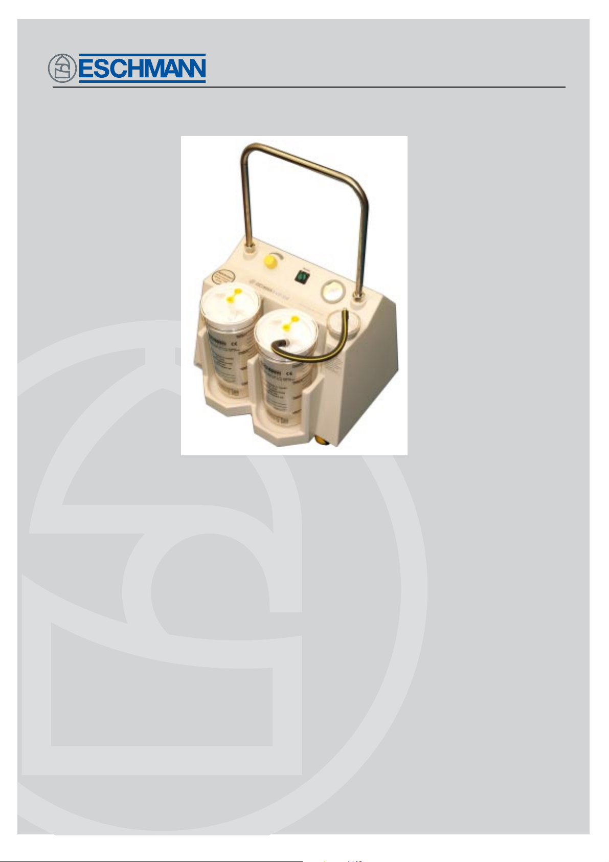
VP35
SUCTION UNIT
Service manual
1 10061
110061
S-SM02e
Page 2
Introduction
Safety notes
Read these Instructions before use
Keep these ‘Instructions’ in a safe convenient place for future reference. Read in
conjunction with the Publications detailed in Section 1.1.
Suction accessories
General care
Maintenance
Parts list
Technical data
Eschmann After Sales Service Department
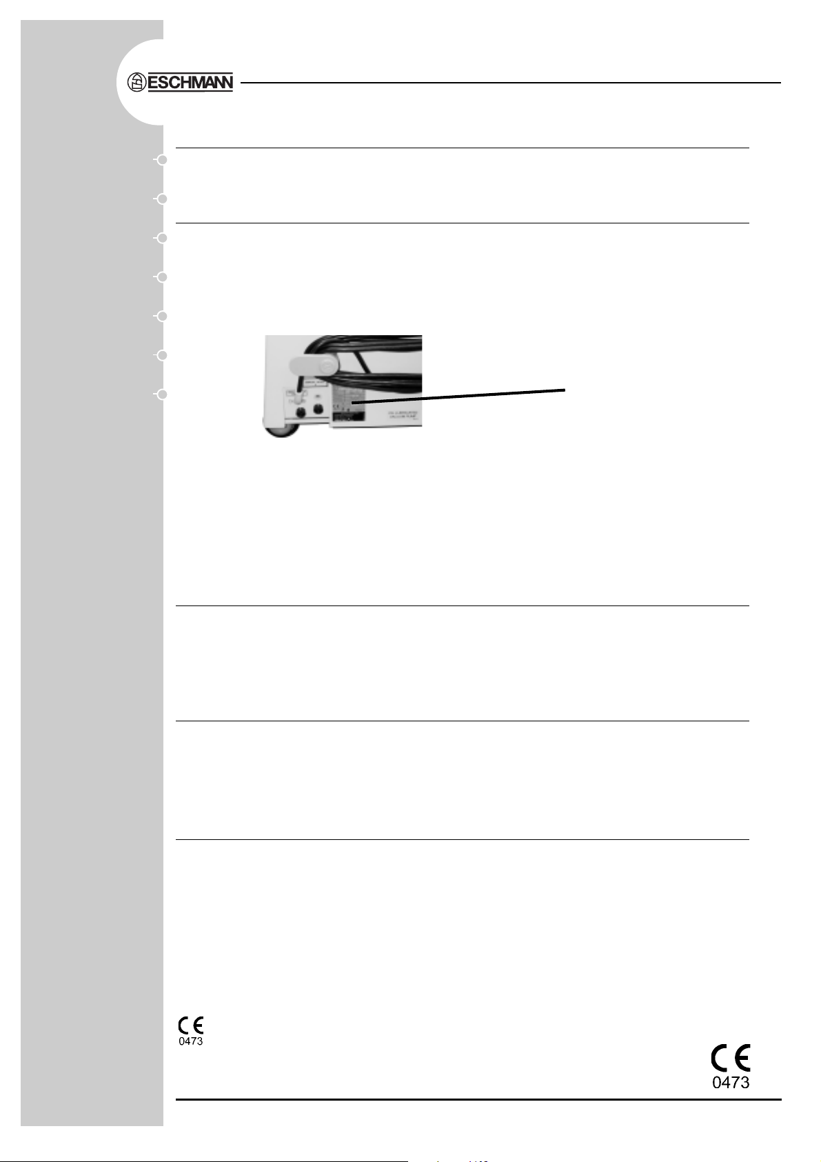
The Eschmann After Sales Service Department is staffed and equipped to provide advice and
assistance during normal office hours. To avoid delays when making enquires, please quote the
Model and Serial Number of your Suction Unit which is shown on the Serial Number plate, the
location of which is shown below. Please ensure you include all alpha and numeric digits of the
Serial Number.
Serial Number
Plate
For further information visit www.eschmann.co.uk
All correspondence relating to the after sales service of Eschmann Equipment to be addressed to :
UK Customers
Eschmann Equipment, Peter Road, Lancing, West Sussex BN15 8TJ, England.
T el: +44 (0) 1903 765040. Fax: +44 (0) 1903 762006.
Overseas Customers
Contact your local distributor. In case of doubt contact Eschmann Equipment.
Patents and Trade marks
The ESCHMANN name and logo are registered trade marks of Eschmann Holdings Limited.
“Eschmann Equipment” is a trading name of Eschmann Holdings Limited .
“VP35” is a trade mark of Eschmann Holdings Limited .
Patents : Patents Pending. (Application number 0124126.4)
Copyright © 2003
All rights reserved. This booklet is protected by copyright. No part of it may be reproduced, stored in a
retrieval system or transmitted in any form or by any means, electronic, mechanical, photocopying,
recording or otherwise without written permission from Eschmann Holdings Limited.
The information in this publication was correct at the time of going to print. The Company, however,
reserves the right to modify or improve the equipment referred to.
NOTE: This Service Manual applies to Suction Units:
REF 82-201-66 2-Jar with Eschmann disposable suction liner system, 230V
REF 82-201-66-9999 2-Jar, with Eschmann suction jars, 230V
REF 82-201-31 2-Jar (traditional pattern), 230V
REF 82-201-80 Unit only with Receptal brackets, 230V
REF 82-201-74 2-Jar with Eschmann disposable suction liner system, 1 10V
REF 82-201-58 2-Jar (traditional pattern), 110V
with Serial Number V3? B 0 C 0000 or later for traditional pattern jars, or with Serial Number V3?
C 0 C 0000 or later for Eschmann disposable suction liner system, where ‘?’ indicates the model variant.
If the CE mark is affixed to the product, it indicates compliance with Council Directive
93/42/EEC of 14 June 1993 concerning medical devices.
S-SM02e August 2003
Service manual
Page 3
VP35 Suction Unit - Service Manual
READ THIS SERVICE MANUAL BEFORE USE
Keep this Service Manual in a safe convenient place for future
reference during cleaning and maintenance procedures.
CONTENTS
SECTION PAGE
1. INTRODUCTION.....................................................................4
General...........................................................................4
Pump and Motor .............................................................4
2. SAFETY NOTES.....................................................................5
3. SUCTION ACCESSORIES .....................................................5
4. GENERAL CARE ....................................................................6
Cleaning .........................................................................6
Sterilisation .....................................................................6
Suction unit disinfection..................................................6
Daily checks ...................................................................6
5. MAINTENANCE ......................................................................7
General...........................................................................7
Checking suction performance .......................................7
Checking pump oil ..........................................................7
Pump blade replacement and pump cleaning ................8
Exhaust filter/silencer replacement.................................8
Fault diagnosis ...............................................................10
6. PARTS LIST ...........................................................................11
Pump/Motor unit .............................................................11
Suction unit.....................................................................12
7. TECHNICAL DATA..................................................................14
APPENDIX A For units with traditional jar assemblies .............15
APPENDIX B For units with Eschmann Suction Jars...............16
FIGURES Fig.1VP35 Mobile suction unit........................................4
Fig.2Pump motor assembly ...........................................7
Fig.3Pump and motor exploded view.............................9
Fig.4Pump rotor blade replacement ...............................9
Fig.5VP35 Circuit diagram .............................................9
Fig.6Oil lubricated vacuum pump - spares items ...........11
Fig.7VP35 Suction unit - identification for parts list ........12
Fig.8Traditional jar and jar top assembly .......................15
S-SM02e Page 3 of 16
Page 4

Section 1
GENERAL
1.1 The VP35 is a high vacuum, high flow suction unit designed to conform with British
and International Standards EN 60601-1:1990+A1:1993+A2:1995, ISO 10079-1:1991,
BS 5724:Part 1:1979, IEC 601-1:1977, IEC 601-1-2:1993.
1.2 The suction unit can be supplied in three ways; either with a reusable jar and
disposable liner system as illustrated below in Fig. 1, or with T raditional Jars (see appendix
A), or with Eschmann Suction Jars (see Appendix B), or without jars and liners but
incorporating brackets to receive ‘Abbott Receptal’ style disposable items.
PUMP AND MOTOR
1.3 The vacuum pump is an oil lubricated electrically driven pump/motor unit of the rotary
vane type, with replaceable blades. The motor unit is designed to operate from the mains
electrical supply (see serial plate for unit voltage).
1.4 The pump/motor unit, its associated pipework and electrical connections are all
contained within a durable, hygienic plastic case. Controls are mounted on the top of the
case and comprise an illuminated* on/off power switch, a vacuum control valve and gauge.
VP 35 Suction Unit - Service Manual
1. INTRODUCTION
(* On later units the switch is not illuminated.)
1.5 A silencer unit in the pump exhaust line ensures that the pump operates with the
minimum of noise, while the pump inlet is protected by an externally mounted sealed
bacterial or combined hydrophobic/bacterial filter, both of which are disposable.
1.6 All the information necessary to maintain the VP35 portable suction unit in a
serviceable condition will be found in this Service Manual.
Fig. 1 VP35 Mobile suction unit
Page 4 of 16 S-SM02e
Page 5
VP35 Suction Unit - Service Manual
2. SAFETY NOTES
When servicing or maintaining the ESCHMANN VP35 SUCTION UNIT,
attention to the following points will prolong the life of the unit.
Section 2 & 3
DO clean and disinfect all suction equipment
and the unit thoroughly after use.
DO change the disposable filter after each
day’s use, or, IMMEDIATELY if wetted,
or, after aspiration of infective fluids.
DO unplug and/or isolate power lead before
cleaning suction unit and when not in use.
DO treat receiver jars carefully, avoiding
mechanical or thermal shock.
DO examine condition of jars, lids (including
float function) and suction tubing
regularly, replace if worn or damaged.
DO keep ‘sharps’ away from liners.
WARNING
The maintenance procedures described in this User Handbook should be made the
responsibility of the engineer in charge of services in the hospital. If maintenance is
neglected, suction performance could be found inadequate in an emergency situation.
It is also recommended that if placed on standby for emergency duty the unit is
tested by switching on, at regular intervals. Also consult the Instructions for Use for
additional warnings on safe use and the disposal of potentially contaminated liquid,
or solid, waste.
DON’T start unit without removing the
transit bolt and washer.
DON’T use substitute accessories (see
available parts list).
DON’T continue to use unit, without
attention, if vacuum or suction rate
is low.
DON’T use the mains lead or suction tubing
as a tow rope, use the unit’s handle.
DON’T use phenols or solvent based
disinfectants to clean receiver jar,
use Savlon, Hibitane or similar
(also see sections 4.1 - 4.3).
3. SUCTION ACCESSORIES
Filters (10, bacterial) ....................................................................... REF 82-961-68
Filters (10, hydrophobic/bacterial)................................................... REF 82-961-85
Jar (traditional) ................................................................................ REF 82-901-13
Tapered connector.......................................................................... REF 82-923-88
Incineration box (pack of 25)........................................................... REF 82-923-96
Suction tubing 6.35mm i.d. ............................................................. REF 82-929-14
Suction tubing (black) 12.7mm i.d................................................... REF 82-930-15
Suction tubing (clear) 12.7mm i.d. .................................................. REF 82-931-12
Disposable liner, standard bore 8.5mm (box of 25) ........................ REF 82-923-57
Disposable liner, wide bore 12.5mm (box of 25)............................. REF 82-923-69
Disposable liner, Cascade, standard bore 8.5mm (box of 25) ........ REF 82-923-65
Critical measuring vessel (CMV) (box of 12)................................... REF 82-929-77
Jar for disposable liner.................................................................... REF 82-923-61
Cascade connecting tube (box of 50) ............................................. REF 82-929-36
Pump oil .......................................................................................... Part No.744092
For all other spare part information see the Parts Lists in section 6, Appendix A and
Appendix B.
S-SM02e Page 5 of 16
Page 6
Section 4
VP 35 Suction Unit - Service Manual
4. GENERAL CARE
CLEANING
WARNING
The equipment must be disconnected
from the mains electrical supply prior
to cleaning and disinfection.
4.1 The following routine should be carried
out immediately after each period of use:
i. Disposable filters must be changed after
each day's use, or IMMEDIATELY if
wetted, or after aspiration of infective fluids.
ii. All components likely to be in contact with
aspirated body fluids should be thoroughly
cleaned and sterilized after use, or
whenever it is suspected that infective
fluids have been in contact with the unit.
iii. The outside of the suction unit should be
washed with hot (55°C) detergent
solution, e.g. 0.1% Teepol or equivalent,
rinsed with clean water, and wiped dry.
iv. The jar inlet tube can be cleaned by
removing the jar lid and flushing the tube
through with water under pressure.
v. In case of undue frothing, for example,
moisture could be sucked past the cutoff
valve. If wetting of the filter indicates that
this has happened, the cutoff valve
assembly must be disinfected.
vi. Should the float cage, or rubber valve seat
be damaged in any way, the complete
cutoff valve assembly must be renewed.
vii. Phenol based disinfectants and solvent-
based liquids should not be used for
cleaning receiver jars, use aqueous
based liquids at all times.
STERILIZATION
method of sterilization for the jars is steam
autoclaving, if chemical techniques are to
be used only use aqueous based systems.
4.3 Jars and lids should be thoroughly
cleaned before autoclaving and all traces
of cleaning liquids removed by adequate
rinsing in water. (Also see section ‘vii’ of
section 4.1).
SUCTION UNIT DISINFECTION
4.4 The suction unit should be moved to a
well-ventilated area designed and used as
the disinfection area. Access to the area
should be restricted to those people involved
in the disinfection process. Initially the unit
should be cleaned as detailed above [4.1(iii)] and then disinfected as below:
i Wash down all surfaces and crevices with
a 70% solution of industrial methylated
spirit and water. Allow drying by
evaporation at room temperature.
ii All infected or soiled cleaning materials
should be disposed of safely and carefully ,
taking into account any National, Local or
Hospital procedures covering the disposal
of potentially contaminated waste.
DAILY CHECKS
4.5 To ensure the VP35 Suction Unit
operates efficiently in an emergency, the
following checks should be carried out daily:
i. Check jar cutoff valve for free movement.
If valve action is faulty , rectify or renew lid
assembly .
ii. Check jar for cracks or chips in rim. Renew
if damaged. Renew rubber bung if
hardened, split or damaged.
CAUTION
To avoid cracking the jar by thermal
shock, place it towards the rear of the
autoclave shelf and open the door
slowly. Do not use phenols or solvent
based disinfectants to sterilise jars.
4.2 The jar lid assembly can be sterilized
by all normal methods including high
pressure autoclaving. The most suitable
iv. With suction unit switched ‘on’, vacuum
control valve turned up to maximum and
suction line blocked off, check reading on
vacuum gauge moves quickly to at least
600mm Hg (atmosphere at 760mm Hg).
Service unit if vacuum value low .
Note: Disposable filters, suction
tubing, jars and disposable liners are
relatively inexpensive items, and a stock of
spares should always be readily available.
Page 6 of 16 S-SM02e
Page 7

VP35 Suction Unit - Service Manual
5. MAINTENANCE
WARNING
Maintenance of the vacuum pump/motor
unit and associated components will
necessitate removal of the suction unit
cover. SWITCH OFF AND DISCONNECT
electrical supply to suction unit before
removing cover.
GENERAL
5.1 Apart from cleaning and filter
replacement, the suction unit does not
require frequent in-depth maintenance. The
pump oil level and condition need only be
checked after every 500 hours or 3 months,
unless contamination is suspected - in which
case the unit must be removed from service
immediately, cleaned and replenished with
fresh oil (see section 5.7). Also the pump
rotor blades should be examined for wear
every three months.
5.2 Should suction performance
deteriorate, it is strongly recommended that
an Eschmann service engineer be called to
deal with the problem (see inside front cover
for details). If this is not possible, then
provided that a competent engineer is
available, items such as blades, oil seal
gasket, oil wick and exhaust filter/silencer
can be examined and, if necessary , renewed
by hospital equipment maintenance staff.
CHECKING SUCTION PERFORMANCE
5.3 If at any time suction performance is poor
this can be due to an air leakage in the system
(e.g. split tubing, poor connection, worn or illfitting jar lids, chipped jar rims), blockage of
the disposable filter or exhaust filter/silencer,
or wear in pump blades or stator.
5.4 If deterioration of suction performance
is due to a blocked filter, the pump will still
produce a satisfactory reading on the
vacuum gauge, but if it is due to leakage in
the system or mechanical wear the vacuum
reading will also be poor. To check vacuum
performance of the suction unit, block off the
suction line by placing a finger over jar lid or
liner inlet nozzle and check the reading
Section 5
1. Pump assembly
2. Motor
3. Inlet non-return valve/adapter
4. Exhaust tube
5. Exhaust filter/silencer
6. Oil reservoir end cover
7. Oil filler plug
Fig. 2 Pump motor assembly
on vacuum gauge. Vacuum reading should
be 600mm Hg (at least) (atmosphere at
760mm Hg) with vacuum control valve
turned to maximum position.
Note: A low indicated vacuum could
also be due to a faulty vacuum gauge. If
there are no leaks and oil condition is
satisfactory, check gauge before assuming
pump mechanical failure.
CHECKING PUMP OIL
5.5 After 500 hours/3 months or if at any
time pump performance deteriorates,
proceed as follows:
i. Switch off pump, remove oil filler plug
(item 7, Fig. 2) and observe level and
condition of pump oil.
ii. If the level of the oil has fallen appreciably ,
add more of the high vacuum oil supplied
until the oil reaches the oil filler hole, then
install the oil filler plug securely. If the oil
appears dirty or contaminated, the oil
reservoir should be disassembled,
cleaned out and replenished with fresh
oil (see under ‘Pump blade replacement
and pump cleaning’ section 5.7).
S-SM02e Page 7 of 16
Page 8

Section 5
VP 35 Suction Unit - Service Manual
5. MAINTENANCE
5.6 After 12 months use, the pump oil
reservoir should as a matter of routine
servicing, be disassembled, cleaned and
replenished with fresh oil.
PUMP BLADE REPLACEMENT and
PUMP CLEANING
CAUTION
The pump oil reservoir (item 10, Fig. 3)
and its front cover (item 1, Fig. 3) can be
removed for cleaning and blade
replacement purposes. Beyond this
point, disassembly should only be
undertaken by an Eschmann Service
Engineer. If a situation occurs where this
is necessary, in the absence of
Eschmann personnel, advice should first
be sought from Eschmann Equipment
or their local representative.
5.7 T o gain access to the pump/motor unit,
disconnect the electrical supply to the unit
and remove the suction unit top cover. In
order to carry out pump disassembly the
pump/motor unit must be removed from the
suction unit baseboard by removing the
fixing screws from the motor feet. Now refer
to Fig. 3 and proceed as follows:
i. Remove the oil filler plug (4) and drain all
the oil from the pump.
ii. Mark with a file the relative fixed positions
of pump stator (12), oil reservoir (10) and
end cover (1).
iii. Release and extract the four long screws
(8) from the oil reservoir end cover (1),
then separate the end cover and oil
reservoir from the pump stator .
lubricate each blade with Eschmann
‘Universal’ high vacuum pump oil before
inserting blades into their slots.
v. If the oil was dirty or contaminated,
thoroughly rinse-out the interior of the oil
reservoir, the pump stator, the rotor slots
and the inside face of the end cover . Use
only disinfectant and warm water or mild
organic solvents. When making up a
disinfectant solution avoid the use of
hypochlorites, which could damage the
pump interior surfaces. If the pump interior
has been badly contaminated, it may be
necessary to carry out further
disassembly in order to gain access to all
internal surfaces; this should be the
responsibility of an Eschmann Service
engineer (see cautionary note above
section 5.7). Rinse and dry all washed
components thoroughly, before
reassembling.
vi. Apply a film of clean high vacuum pump
oil to the stator bore, then reassemble the
pump components, fitting a new cork
gasket (9) and, if necessary , a new oil wick
(1 1). Align oil reservoir (10) and end cover
(1) with stator (12) by means of the file
markings, insert the four long screws (8)
and tighten them evenly and securely.
vii. Finally , add a charge (25ml) of fresh oil to
the oil reservoir, via the oil filler hole in the
end cover, using Eschmann ‘Universal’
high vacuum pump oil (see spares list).
Install the oil filler plug securely.
EXHAUST FILTER/SILENCER
REPLACEMENT
iv . Pump blades will eventually wear after a
long period of use; the minimum root to
tip dimension which a blade should be
allowed to reach is 11mm (Fig. 4). Note
the facing positions of the four pump
blades then extract each one, examine it
for wear or signs of damage and if
replacement is necessary change all four
blades at the same time (refer to Fig. 3).
Clean out rotor slots then clean and
5.8 The exhaust filter/silencer (item 7,
Fig. 3) which serves the double purpose of
arresting oil mist and reducing exhaust noise
cannot be serviced. Whenever the pump is
disassembled for cleaning or blade
inspection, or if it is noted that the filter/
silencer has become choked or fouled, it
should be renewed as a complete item. If a
filter/silencer is allowed to remain in this
condition, this could also cause loss of flow.
Page 8 of 16 S-SM02e
Page 9

VP35 Suction Unit - Service Manual
5. MAINTENANCE
Section 5
Fig. 3 Pump and Motor exploded view
Fig. 4 Pump rotor blade replacement
Fig. 5 VP35 Circuit diagram
S-SM02e Page 9 of 16
Page 10

Section 5
FAULT DIAGNOSIS
5.9 The following table lists faults, possible causes and remedies that can be rectified
during maintenance procedures. Other faults and possible causes, with remedies that
can be undertaken by the user, are dealt with in the suction units ‘Instructions for Use’.
Electrical faults should be traced and rectified in conjunction with circuit diagram (Fig.5).
For any causes not listed and which cannot be resolved, please contact the Eschmann
After Sales Service Department.
Fault Possible Cause Remedy
1. Total loss of (a)Motor failure (a)Renew pump/motor unit
suction (also (b)Electrical wiring fault (b)Rectify as necessary
see 3 below) (c) Aspirated material in pump (c) Strip and clean, or
VP 35 Suction Unit - Service Manual
5. MAINTENANCE
FAULT DIAGNOSIS CHART
(pump seized) renew pump/motor
2. Vacuum gauge (a)Loss of vacuum (a)See (1) above
- no indication (b) Faulty gauge (b)Renew gauge
3. No power (switch (a)Burnt-out fuse in mains plug or unit (a)Check/replace fuses
indicator lamp* (b)Break in mains supply cable (b)Rectify or replace
fails to illuminate) (c) Indicator lamp failed (c) Renew power switch
4. On switching (a) Failure of pump inlet (a)Replace valve
pump off with non-return valve
inlet blocked
- immediate
loss of vacuum
5. Oil collecting (a)Failure of oil seals/O-rings (a)Renew
beneath oil reservoir
6. Oil mist escaping (a) Exhaust filter/silencer unit (a)Renew filter/silencer unit,
from exhaust outlet unserviceable or unit has check reservoir has not
in filter/silencer unit been tipped over. been overfilled.
7. Vacuum control (a) Faulty valve (a)Replace valve
valve not operating.
* On later models the power switch does not incorporate an indicator lamp.
Note: A thermal overload switch, which is self-resetting, is incorporated to protect the
motor in the event of pump seizure or excessive running temperatures. Should the
overload switch operate to stop the motor it is essential to disconnect the electrical
supply to the unit before attempting any form of maintenance.
Page 10 of 16 S-SM02e
Page 11

VP35 Suction Unit - Service Manual Section 6
6. PARTS LIST
Fig. 6 Oil Lubricated vacuum pump - spares items
Fig. 6 Part Description No. Recommended
Item No. No. off Spares #
- 733584 Pump/Motor Unit, lubricated (230V a.c.) 1 or 733585 Pump/Motor Unit, lubricated (100/120V a.c.) 1 1 759241 . Cover, oil reservoir 1 2 759242 . Adapter, hose 1 3 759156 . Valve, non-return/adapter 1 4 640631 . Plug, 1/4-BSP 1 5 710794 . Washer, fibre 1 6 695026 . Hose, 1/4 in. i.d. 1 1
7 759243 . Filter/silencer unit, exhaust 1 1
8 710117 . Screw, pan hd. M5 x 60 long 4 9 759244 . Gasket, cork 1 1
10 759245 . Reservoir, oil 1 11 759246 . Wick, oil 1 1
12 759247 . Stator 1 13 710115 . Screw, pan hd., slotted, M4 x 20 long 2 -
- - . Rotor assembly 1 14 795248 . . Rotor 1 15 759153 . . Pad, brass 1 16 759158 . . Screw, skt, set, dog pt. M5 x 10 long 1 17 759249 . . Blade, fibre/resin 4 4
18 652326 . O-ring, 104.5 i.d. x 3.0 section 2 19 759250 . Plate, mounting 1 20 759161 . Screw, pan hd. slotted, M5 x 16 long 2 21 710763 . Washer, copper, M5 nom. 2 22 759251 . Joint, paper, mounting plate 1 23 759162 . Finger, felt 1 24 759238 . Motor 230V, a.c. 50/60Hz 1 Miscellaneous
744092 Oil, high vacuum, Eschmann ‘Universal’ (500ml bottle) 1 1
# The spares holding column indicates recommended spares
for one unit of equipment for one year only.
S-SM02e Page 11 of 16
Page 12

Section 6
11
VP 35 Suction Unit - Service Manual
6. PARTS LIST
Part rear view
15
5
2
9
25
1
A
27
A
A
A = Accessory see 'Suction accessories - Parts List', Appendix A and Appendix B.
4
14
3
26
22,23
10
3
13
13
16
19
18
13
8
22,23,24
20
21
6
17
7
Fixings for itemised parts,
are detailed in the parts list,
following each item.
Fig. 7 VP35 Suction unit - identification for parts list
Page 12 of 16 S-SM02e
Page 13

VP35 Suction Unit - Service Manual
Section 6
6. PARTS LIST
Fig. 7 Part Description No. Recommended
Item No. No. off Spares #
1 743077 Vacuum gauge and fixings 1 -
743033 . Vacuum gauge clamp 1 2 696499 Mains switch, on/off, (illuminated on early units only) 1 3 695068 Mount, filter unit 1 -
683821 . Filter mount locking rings 3 4 713114 Cabinet, moulded 1 -
710151 . M6 x 10mm soc. hd. screw 6 5 712949 Valve, vacuum control 1 6 646935 Castor (set of four, 2 left and 2 right) 1 set -
710847 . M8 half-nut 4 -
710703 . M8 washer 8 7 730031 Mount, AVA 6 -
710702 . M6 plain washer 6 8 733584 Pump/motor unit 230V a.c. 1 or 733585 Pump/motor unit 100/120V a.c. 1 9 - Reversible cleat for cable stowage comprising 2 of each:-
743081..Moulded arm 743082. Moulded boss 745189 .Moulded insert
709834..M6x40mm screw 693107 . Special M6 washer 683184 .Spring
710702..M6 plain washer 710882 . M6 nut
10 744119 Cable, mains supply 5m -
696241 . Mains cable gland and clamp 1 -
710734 . M3 shakeproof washer 2 11 743053 Handle with locking nuts 1 12 743072 Spanner for handle (not illustrated) 1 13 718517 Hose assembly complete, with ‘T’ connections 1 14 713632 Backing plate 1 15 713638 Mounting bracket, ‘V’ shaped 2 -
710224 . M4 x 25mm soc. hd screw 4 16 718518 Exhaust filter/silencer assembly with hoses 1 1
17 713088 Motor mounting/transit plate 1 18 713601 Baseplate 1 19 743075 Exhaust filter support 1 20 696227 Terminal block 2-way (use insulation pad 713603) 1 -
710133 . M3 x 20mm ch.hd. screw 1 21 696228 Terminal block 4-way (use insulation pad 713604) 1 -
710133 . M3 x 20mm ch.hd. screw 2 22 744121 Neutral fuse holder (for fuse see Technical data) 1 23 744122 Live fuse holder (for fuse see Technical data) 1 24 697497 Fuse cover (boot) 2 25 695278 Exhaust nozzle 1 26 713654 Filter hose assembly 1 1
27 713582 Angled connector 1 5
Miscellaneous items and fixings used as required:-
606312 Cable tie base, self adhesive 670650 Screw retainer
695776 Cable tie, small 695777 Cable tie, large
Miscellaneous earth connections, cable assemblies and sleeving etc.:-
710841 M5 nut 709862 M5 plain washer
693640 Metway clamping washer 710802 M5 shakeproof washer
697395 Sleeving 710091 M5 x 10mm pan head screw
713218 Earth cable assembly 713127 Switch cable assembly
Miscellaneous items used on some models only:-
711481 Receptal holders 695233 2 litre jar pads
# The spares holding column indicates recommended spares for 1 unit of equipment for 1 year only.
S-SM02e Page 13 of 16
Page 14

Section 7
GENERAL
Equipment Type ............................................ Mobile, medical suction unit.
Pump Type.................................................... High vacuum, high flow, oil lubricated
Oil charge............................................ 25ml (approx.), Part No. 744092.
Performance:
Maximum airflow rate - 38 litre/min Maximum vacuum - 600 mm Hg (80kPa)
Electric motor ................................................ Totally enclosed, fan cooled, 90W.
Mains input (see Serial Number plate) .......... 230V a.c. 50/60Hz, or 100/120V a.c. 50/60Hz
Fuses (2 off) for 230V supply ........................ T 2 A anti-surge (Part No. 696188)
(2 off) for 100-120V supply................... T 5 A anti-surge (Part No. 696775)
Disposable Liner System:
Disposable Liner..................................... PVC fabrication with 100 ml graduations
Overflow protection................................. Float type cutoff valve (if applicable).
Capacity ................................................. 1500ml (approx.) working volume.
Disposal.................................................. By incineration.
Overall dimensions:
Height - 670 mm Width - 440 mm Depth - 410 mm
Net weight (typical)........................................ 12.4 kg
VP 35 Suction Unit - Service Manual
7. TECHNICAL DATA
rotary vane type, mains operated.
Duty Cycle continuous.
with integral handles, ‘patient’ and
‘vacuum’ connections.
SAFETY
Standards : EN 60601-1:1990+A1:1993+A2:1995, ISO 10079-1:1991,
BS 5724:Part 1:1979, IEC 601-1:1977
Classification : Class 1. Type BF Drip proof
Electromagnetic compatibility : IEC 601-1-2:1993
Filters: Sealed disposable Hydrophobic/bacterial type, designed to provide 100% pump
protection against aqueous fluids, or, Sealed disposable Bacterial type.
CLASS Class 1 denotes that the equipment must be earthed via the protective conductor
in the 3-core mains cable connected to a 3-pin plug.
EXPLANATION OF SYMBOLS
DRIP PROOF The symbol (drip proof) indicates that the equipment will withstand a
moderate quantity of water spilled from above the unit.
SAFETY CA TEGOR Y The symbol denotes that the equipment is in the category type
BF, i.e. that it is manufactured to a safety standard commensurate with international
regulations for medical electrical equipment incorporating floating patient applied parts.
SUPPL Y The symbol indicates that the equipment is for use on alternating current only.
V ACUUM CONTROL The symbol indicates that vacuum is increased by clockwise
rotation of this control.
This symbol denotes ‘Single Use’
Page 14 of 16 S-SM02e
Page 15

VP35 Suction Unit - Service Manual
Appendix A
APPENDIX A
ADDITIONAL INSTRUCTIONS FOR UNITS WITH TRADITIONAL JAR ASSEMBLIES
INTRODUCTION
A1 This Appendix contains additional information for units with traditional jar assemblies.
DAILY CHECKS
A2 Additional checks (also see section 4.5) should be carried out on a daily basis as follows:
i. Check condition of ‘float valve rubber seat’ (item 7, Fig. 8) in underside of jar bung, if it is
torn, cracked or hardened, renew it.
ii. Check jar rubber bungs for condition. If hardened, split or damaged, it is advisable to
renew the complete jar top assembly.
CLEANING
A3 The following additional cleaning procedures (also see section 4.1) should be carried
out after each period of use:
i. Connector Block. Avoiding the use of phenol or xylenol based disinfectants, make up a
disinfectant solution in accordance with manufacturer’s instructions. Wearing protective
gloves, immerse connector block in the disinfectant ensuring all internal bends and all uneven
surfaces come into contact with the liquid for the required period of time. (Note: The ‘rubber
valve seat’ in the jar bung is a moulded insert and should be removed for cleaning).
STERILISATION
A4 See section 4.
PARTS LIST
Fig.8 Part Description No.
Item No. No. off
1 744029 Connector block, anticonfusion c/w inlet 1
nozzle, 6.5mm bore for standard use.
2 730010 Tube, rubber, antistatic, 12.7mm o.d. x 6.35mm i.d. As reqd.
4 - Jar, 2 litre, Traditional pattern, REF 82-901-13 2
5 712954 Jar top with inlet tube assembly for 2 litre jar 1
6 712956 . Bung, jar 1
7 733506 . Valve seat, rubber 1
8 712955 . Inlet tube 1
9 733589 . Float valve and cage assy. 1
5
6
7
9
8
Fig. 8 Traditional jar and jar top assembly
S-SM02e Page 15 of 16
Page 16

VP 35 Suction Unit - Service Manual
APPENDIX B
ADDITIONAL PARTS FOR UNITS WITH ESCHMANN SUCTION JARS
Vacuum outlet
Patient inlet
Inlet tube
‘V’ bracket
T apered connector
Lid
Raised lip on lid rim
Seal
Float type
cut-off valve
Cradle
Clip
Jar
AVAILABLE SPARES
The following spares are available:
Jar only................................................... REF 82-923-10
Jar with cradle only................................. REF 82-923-29
Jar with lid & cradle ................................ REF 82-923-02
Spare jar lid ............................................ REF 82-923-37
Spare cradle ........................................... REF 82-923-45
Tapered connector.................................. REF 82-923-88
Page 16 of 16 S-SM02e
Page 17

Page 18

Eschmann Equipment, Peter Road, Lancing, West Sussex, BN15 8TJ, England.
T el: +44 (0) 1903 753322. Fax: +44 (0) 1903 766793. www.eschmann.co.uk
 Loading...