

Page 1
TD830
E LECT RO SURGICAL UNIT
Service Manual
698260
E-SM44h
Page 2
Preliminary
Information
Technical data
Read these Instructions before use
Keep this ‘Service Manual’ in a safe convenient place for future reference. Read in conjunction
with the relevant Publications detailed in the preliminary information section.
Safety notes
and alarms
Introduction
Description
Maintenance
Illustrated parts list
Eschmann After Sales Service Department
The Eschmann After Sales Service Department is staffed and equipped to provide advice and
assistance during normal office hours. To avoid delays when making enquiries, please quote the
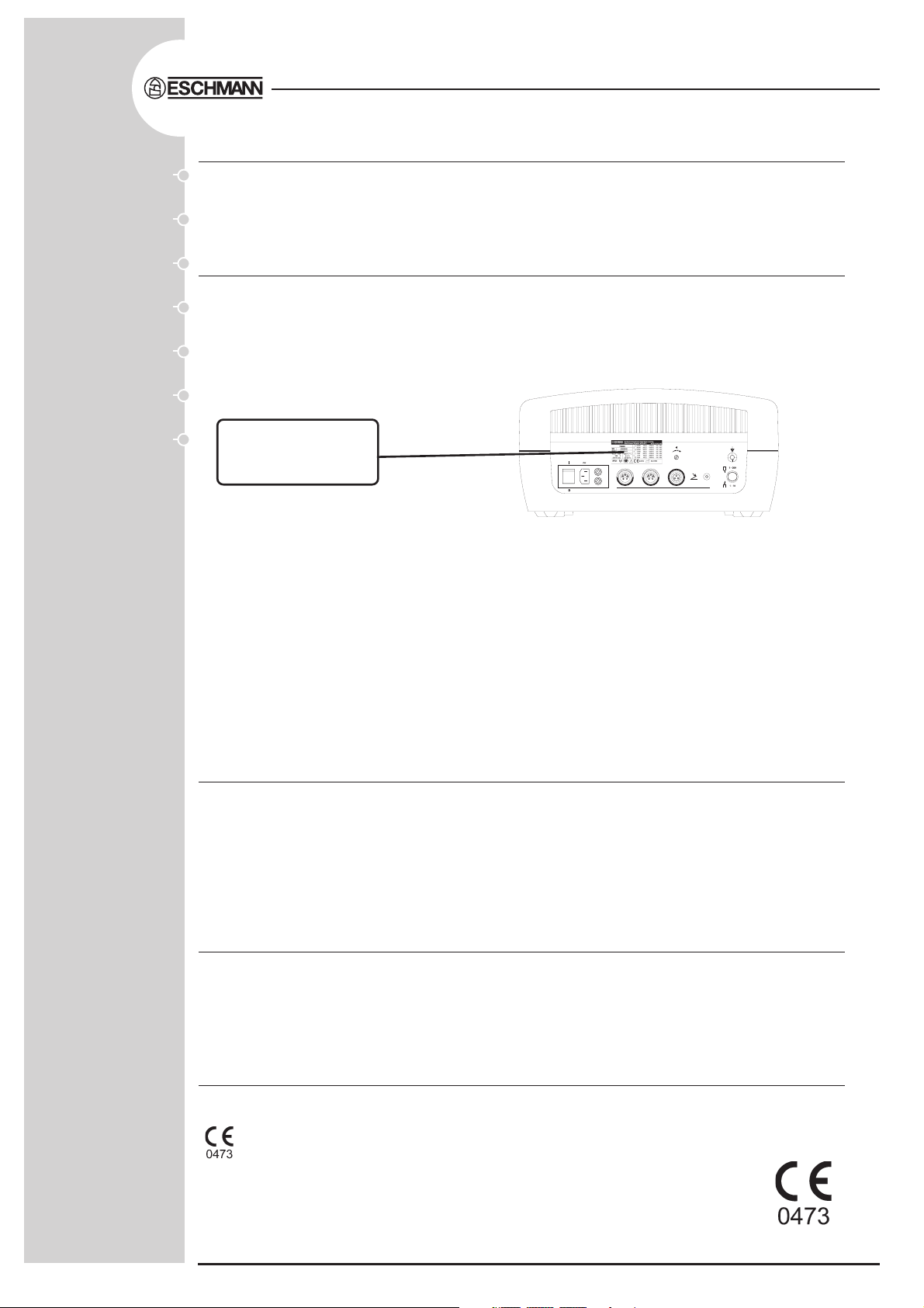
Model and Serial Number of your Electrosurgical Unit which is shown on the Serial Number plate,
the location of which is shown below. Please ensure you include all alpha and numeric digits of
the Serial Number.
The Serial Number plate
is located here, (view
from rear of unit).
For further information visit www.eschmann.co.uk
All correspondence relating to the after sales service of Eschmann Equipment to be addressed to :
UK Customers
Eschmann Equipment, Peter Road, Lancing, West Sussex BN15 8TJ, England.
Tel: +44 (0) 1903 765040. Fax: +44 (0) 1903 875711.
Overseas Customers
Contact your local distributor. In case of doubt contact Eschmann Equipment.
Patents and Trade marks
The ESCHMANN name and logo are trade marks of Eschmann Holdings Limited.
“Eschmann Equipment” is a trading name of Eschmann Holdings Limited.
“TD830” and “Flexoplate” are trade marks of Eschmann Holdings Limited.
Patents : GB2276551, GB2146534, AU673883, ZA94/2173, US5480399,
EP617925, IEE69100 and other Patents Pending.
Copyright © 2008 Eschmann Holdings Limited
All rights reserved. This booklet is protected by copyright. No part of it may be reproduced, stored in a
retrieval system or transmitted in any form or by any means, electronic, mechanical, photocopying,
recording or otherwise without written permission from Eschmann Holdings Limited.
The information in this publication was correct at the time of going to print. The Company, however,
reserves the right to modify or improve the equipment referred to.
The CE marking affixed to the product certifies that it complies with the
European Medical Devices Directive 93/42/EEC and related legislation.
Service Manual
E-SM44h July 2008
Page 3

CONTENTS
TD830TD830
TD830
TD830TD830
ELECTROSURGICAL UNIT
1.0 PRELIMINARY INFORMATION
Preliminary information . . . . . . . . . . . . . . . . . . . . . . . . 4
2.0 TECHNICAL DATA
General . . . . . . . . . . . . . . . . . . . . . . . . . . . . . . . . . . . 5
Dimensions . . . . . . . . . . . . . . . . . . . . . . . . . . . . . . . . . 5
Electrical data . . . . . . . . . . . . . . . . . . . . . . . . . . . . . . . 5
Audible indicators . . . . . . . . . . . . . . . . . . . . . . . . . . . . 6
Visual indicators . . . . . . . . . . . . . . . . . . . . . . . . . . . . . 6
Safety.. .. . . . . . . . . . . . . . . . . . . . . . . . . . . . . . . . . . . 6
Duty cycle . . . . . . . . . . . . . . . . . . . . . . . . . . . . . . . . . . 7
Other symbols . . . . . . . . . . . . . . . . . . . . . . . . . . . . . . . 7
Button symbols . . . . . . . . . . . . . . . . . . . . . . . . . . . . . . 8
Alarm symbols . . . . . . . . . . . . . . . . . . . . . . . . . . . . . . . 8
Environmental conditions . . . . . . . . . . . . . . . . . . . . . . . 8
3.0 SAFETY NOTES & ALARMS
Do’s and Don’ts . . . . . . . . . . . . . . . . . . . . . . . . . . . . . . 9
Alarm circuits . . . . . . . . . . . . . . . . . . . . . . . . . . . . . . . 10
4.0 INTRODUCTION
General .. . . . . . . . . . . . . . . . . . . . . . . . . . . . . . . . . . 11
Operating modes / display option.. . . . . . . . . . . . . . . . 11
Accessories . . . . . . . . . . . . . . . . . . . . . . . . . . . . . . . . 11
Associated Publications . . . . . . . . . . . . . . . . . . . . . . . 11
Equipment certification . . . . . . . . . . . . . . . . . . . . . . . 11
Servicing .. . . . . . . . . . . . . . . . . . . . . . . . . . . . . . . . . . 11
5.0 DESCRIPTION
Construction . . . . . . . . . . . . . . . . . . . . . . . . . . . . . . . 14
Sub assembly descriptions . . . . . . . . . . . . . . . . . . . . 14
Front panel . . . . . . . . . . . . . . . . . . . . . . . . . . . . . . 14
Rear panel . . . . . . . . . . . . . . . . . . . . . . . . . . . . . . 14
Mains transformer & rectification assy. . . . . . . . . . 15
Main printed circuit board assembly . . . . . . . . . . . 15
Patient interface PCB . . . . . . . . . . . . . . . . . . . 15
Patient interface (plate) PCB . . . . . . . . . . . . . . 16
Tone generator PCB . . . . . . . . . . . . . . . . . . . . 16
PSU PCB . . . . . . . . . . . . . . . . . . . . . . . . . . . . 16
Bipolar PCB . . . . . . . . . . . . . . . . . . . . . . . . . . . 16
Crowbar PCB . . . . . . . . . . . . . . . . . . . . . . . . . 16
PCM DC regulator PCB . . . . . . . . . . . . . . . . . . 17
Monopolar Power Amplifier PCB . . . . . . . . . . . 17
Spray and Monopolar PCB . . . . . . . . . . . . . . . 17
Relay PCB . . . . . . . . . . . . . . . . . . . . . . . . . . . . 17
Logic and pulse PCB . . . . . . . . . . . . . . . . . . . . 18
Power output graphs . . . . . . . . . . . . . . . . . . . . . . . . . 18
Monopolar cut diagrams . . . . . . . . . . . . . . . . . . . . 19
Monopolar blend diagrams . . . . . . . . . . . . . . . . . . 20
Monopolar specialist cut diagrams . . . . . . . . . . . . 21
Monopolar pinpoint coag diagrams . . . . . . . . . . . . 22
Monopolar spray coag diagrams . . . . . . . . . . . . . . 23
Bipolar macro diagrams . . . . . . . . . . . . . . . . . . . . 24
Bipolar micro diagrams . . . . . . . . . . . . . . . . . . . . . 25
6.0 MAINTENANCE
Routine check . . . . . . . . . . . . . . . . . . . . . . . . . . . . . . 26
Systems check . . . . . . . . . . . . . . . . . . . . . . . . . . . . . 26
Cleaning disinfection and care . . . . . . . . . . . . . . . . . . 26
Access for maintenance . . . . . . . . . . . . . . . . . . . . . . 26
Top cover . . . . . . . . . . . . . . . . . . . . . . . . . . . . . . . 26
Front panel . . . . . . . . . . . . . . . . . . . . . . . . . . . . . . 26
Rear panel . . . . . . . . . . . . . . . . . . . . . . . . . . . . . . 26
Removal and installation . . . . . . . . . . . . . . . . . . . . . . 26
Circuit board removal (except crowbar) . . . . . . . . 26
Crowbar board removal . . . . . . . . . . . . . . . . . . . . 26
Rivet removal/replacement . . . . . . . . . . . . . . . 26
Circuit board replacement . . . . . . . . . . . . . . . . . . . 27
Supply faults . . . . . . . . . . . . . . . . . . . . . . . . . . . . . . . 27
Fuse renewal . . . . . . . . . . . . . . . . . . . . . . . . . . . . 27
Fault finding . . . . . . . . . . . . . . . . . . . . . . . . . . . . . . . . 27
Alarms . . . . . . . . . . . . . . . . . . . . . . . . . . . . . . . . . 27
Alarm remedies . . . . . . . . . . . . . . . . . . . . . . . . 27
Extender board . . . . . . . . . . . . . . . . . . . . . . . . . . . . . 28
Frequency of calibration . . . . . . . . . . . . . . . . . . . . . . . 28
Performance checks . . . . . . . . . . . . . . . . . . . . . . . . . 28
General . . . . . . . . . . . . . . . . . . . . . . . . . . . . . . . . . 28
Output waveform timings . . . . . . . . . . . . . . . . . 28
Preparation . . . . . . . . . . . . . . . . . . . . . . . . . . . 28
Timing measurements . . . . . . . . . . . . . . . . . . . 28
Monopolar output currents . . . . . . . . . . . . . . . . 29
Specialist cut boost check . . . . . . . . . . . . . . . . . . 29
Monopolar current limit check . . . . . . . . . . . . . . . . 29
Bipolar output current . . . . . . . . . . . . . . . . . . . . . . 29
Active relay function test . . . . . . . . . . . . . . . . . . . . . . 29
Set up overview . . . . . . . . . . . . . . . . . . . . . . . . . . . . . 29
System diagram . . . . . . . . . . . . . . . . . . . . . . . . . . . . . 29
7.0 ILLUSTRATED PARTS LISTS
Illustrated parts list 1 . . . . . . . . . . . . . . . . . . . . . . . . . 36
Illustrated parts list 2 . . . . . . . . . . . . . . . . . . . . . . . . . 38
Illustrated parts list 3 . . . . . . . . . . . . . . . . . . . . . . . . . 40
Illustrated parts list 4 . . . . . . . . . . . . . . . . . . . . . . . . . 42
ILLUSTRATIONS
Fig. 1 Part identification . . . . . . . . . . . . . . . . . . . . . . . 13
Fig. 2 Using the extender board . . . . . . . . . . . . . . . . 28
Fig. 3 Monopolar mode timing (part 1) . . . . . . . . . . . 31
Fig. 4 Monopolar mode timing (part 2) . . . . . . . . . . . 32
Fig. 5 Biopolar mode timing . . . . . . . . . . . . . . . . . . . . 33
Fig. 6 TD830 System diagram . . . . . . . . . . . . . . . . . . 44
TABLES
Table 1 Mono & Bipolar timings . . . . . . . . . . . . . . . . . 30
Table 2 TD830 set up overview . . . . . . . . . . . . . . . . . 34
E-SM44h P3/44
Page 4

1.0 PRELIMINARY INFORMATION
1.1 This Service Manual should be referred to for details
of the TD830 Electrosurgical Unit, REF 83-256-01,
83-257-02, 83-258-03, 83-259-04, 83-260-05, 83-261-06,
83-262-07, 83-263-08, and 83-264-09 (serial number
A9B0000 or above).
1.2 Within the text of this manual the term ‘coag’ is used
as a common abbreviation of the term ‘coagulation’.
1.3 The TD830 Electrosurgical Unit requires a mains
electrical supply corresponding to the voltage shown on
the electrical rating plate at the rear of the unit. Only use
the mains supply cable supplied. If the plug supplied prefitted is not suitable it should be replaced with a suitable
plug with protective earthing contact.
1.4 If the plug is a fused type, a 10A fuse must be fitted.
CAUTION
It is most important that fuses of the correct
type, size and rating are installed (see Technical
Data).
CAUTION
Read this ‘Service Manual’ carefully and note
ALL of the warnings, cautions and safety notes
contained within. Keep this ‘Service Manual’
close-to-hand at all times for reference.
1.5 Ensure that the unit ‘mains’ switch (42 of Fig. 12) is
in the ‘O’ position and that the output controls are set to
minimum before connecting to, and switching ‘on’, the mains
supply. A complete systems check must be carried out
before using the Electrosurgery Unit (see the ‘Instructions
for use’).
1.6 Instructions for Use and Service Manuals should
be readily accessible for reference prior to and when
operating, cleaning and servicing the TD830 Electrosurgical
Unit. All manuals are available from Eschmann Equipment,
see inside front cover for address details.
Related Technical Publications:-
Instructions for Use - TD830:
Publication number E-IM54, Part No. 698257
Eschmann accessory ‘Instructions for use’:
Publication number E-IM50, Part No.604802
P4/44 E-SM44h
Page 5

TD830TD830
TD830
TD830TD830
ELECTROSURGICAL UNIT
2. 0 TECHNICAL DATA
GENERAL
The TD830 Electrosurgical Unit (or Surgical Diathermy
Unit) is classified as ‘HF surgical equipment’
1
- ‘HF surgical equipment’ is defined as, “Medical
electrical equipment including its associated accessories
intended for the performance of surgical operations, such as
the ‘cutting’ 2 or ‘coagulation’ 3 of biological tissue by means of
high frequency (h.f.) currents”.
2
- ‘Cutting’ is defined as, “Resection or dissection of body
tissue caused by the passage of high frequency current of high
current density at the active electrode(s)”.
3
- ‘Coagulation’ is defined as, “Sealing of small blood
vessels or of body tissue caused by the passage of high
frequency current at the active electrode(s)”.
Equipment - High power electrosurgical unit with
monopolar and bipolar outputs
Type - Portable
DIMENSIONS
Width . . . . . . . . . . . . . . . . . . . . . . . . . . . . . . 39.0 cm
Height . . . . . . . . . . . . . . . . . . . . . . . . . . . . . . 19.0 cm
Length . . . . . . . . . . . . . . . . . . . . . . . . . . . . . .42.5 cm
Weight . . . . . . . . . . . . . . . . . . . . . . . . . . . . . . . . 15 kg
1
Output (bipolar)
Peak
Open
Crest Circuit
Symbol/Function Power factor Voltage
Coagulation
Micro range 17W ±20% Variable 150
Macro range 50W
Power and voltage output data diagrams are shown at the
end of section 5.
+10%
-20%
Variable 230
Monopolar
Carrier frequency - 475kHz nominal, square wave.
Power control - Variable amplitude set by frontpanel
controls. Preset pulse patterns set by mode switches.
Load resistance for maximum output power is 150 ohms
(non-inductive) for cut and pinpoint coag and 200 ohms
(non-inductive) for blend, specialist cut and spray coag.
Test load is 200 ohms (non-inductive) for cut and specialist
cut and 400 ohms (non-inductive) for blend, spray coag
and pinpoint coag.
ELECTRICAL DATA
(Note: Voltage factory set by transformer tapping, according
to model supplied.)
Power Supply . . . . . . . . . . . . . . . . . . 230V a.c., 50-60Hz
or, 240V a.c., 50-60Hz
or, 220V a.c., 50-60Hz
or, 110V a.c., 50-60Hz
Current (max.) . . . . . . . . . 4.4A (230V) or, 4.2A (240V)
or, 4.6A (220V) or, 8.4A (110V)
Fuse rating (240V, 230V, 220V) . . . . . . . . . . . 250V, T5A
Fuse rating (110V) . . . . . . . . . . . . . . . 125V(min.),T10A
Fuse type . . . . . . . . . . . . . . . . . . . . . . . . . . . . . . 20 mm
Bipolar
Carrier frequency - 785kHz nominal, square wave.
Power control - Variable pulse group modu-lation set
by front panel control. Amplitude set by micro/macro range
buttons.
Load resistance for maximum output power
- 100 ohms (non-inductive) for Macro
- 50 ohms (non-inductive) for Micro
Output (monopolar)
Output powers are measured to an accuracy of ±20%, with
a maximum power of 400 watts.
Peak
Open
Crest Circuit
Symbol/Function Power factor Voltage
Normal cut 345W(-20%) 1.9 1150
Blend 300W(±20%) 3.0 2200
Specialist cut 345W(-20%) 2.1 1500
Pinpoint coag. 170W(±20%) 5.1 2150
Spray coag. 79W(±20%) 8.7 4000
Power and voltage output data diagrams are shown at the
end of section 5.
Test load - 100 ohms (non-inductive)
E-SM44h P5/44
Page 6

AUDIBLE INDICATORS
SAFETY
Running tones *
Monopolar
Cut, blend or specialist cut 950Hz
Coagulation, pinpoint or spray 800Hz
Bipolar
Micro or macro 730Hz
(* Approximate values, adjustable volume)
Touch button
A ‘bleep’ indicates when any function button is pressed,
the volume is adjustable with running tones above.
Alarm
All modes - alternating two tone preset to maximum volume
(with flashing display).
VISUAL INDICATORS
Green lamp in mains ‘on/off’ switch to indicate power ‘on’
from the rear of the electrosurgical unit.
Digital displays and ‘function selected’ LEDs indicate power
‘on’ from the front of the electrosurgical unit
Three digital displays indicate
and bipolar modes. (Note: These can be set to display the
typical power*
to 10).
(
* typical power
delivered over a range of load resistances. It is less
than the power delivered to the rated load for maximum
power.)
available in watts, or a numerical value up
is an indication of the average power
typical power*
in cut, coag
General
Designed to comply with EN60601-1:1990 Medical
electrical equipment - general requirements for safety and
IEC60601-2-2: 1998 High-frequency surgical equipment particular requirements for safety (3rd edition).
General classification, Class 1, Type CF (Defibrillator proof).
Drip-proof (IPX 1)
Patient leakage (risk) current: always less than 100
microamps to earth (ground) from all patient circuits at 230V
50Hz as required by EN60601-1:1990 for the unit in normal
condition (typically less than 10 microamps).
Battery
This equipment contains a nickel metal hydride battery. In
the event of failure of the display p.c.b. battery, or if the
electrosurgical unit is to be disposed of, it is not necessary
to remove the battery or to return it to Eschmann
Equipment. The battery charge life is six months from a
full charge of 48 hours. The battery charges automatically
when the unit is ‘on’.
Electrode isolation
The plate electrode circuit of this equipment is isolated
from earth at both high and low frequency. The bipolar
output is also fully isolated at both high and low frequency.
Class
Class 1 denotes that the equipment must be earthed via
the protective conductor in the 3-core mains cable
connected to a 3-pin plug.
Power output ‘activated’ LED indicators for:
Cutting modes Yellow lamp
Coag modes Blue lamp
Bipolar mode Blue lamp
Green and bright green function selected LED indicators
above (or below) the relevant touch buttons detailed as
follows:
Monopolar:
Cut, blend, specialist cut (green)
Pinpoint coag (green)
Spray coag (bright green)
Bipolar:
Micro and macro power range (green)
Safety category
This symbol denotes that the equipment is of type
CF, i.e. that it complies with type CF leakage current
requirements. The symbol also denotes that the equipment
will not be damaged by defibrillator discharge and that the
plate electrode need not be removed from the patient if a
defibrillator is used.
Non-ionizing radiation
This symbol warns the user of the possibility of non-
ionizing radiation being emitted by this equipment.
P6/44 E-SM44h
Page 7

Flammable gases
The TD830 equipment is not suitable for use in the
presence of a flammable anaesthetic mixture with air
or with Oxygen or Nitrous Oxide.
TD830TD830
TD830
TD830TD830
ELECTROSURGICAL UNIT
The symbol on the rear panel serial plate warns the
user to read the accompanying documents, the ‘Instructions
for use’.
Protection
IPX 1 This symbol (drip proof) denotes that the
equipment meets the requirements of IEC529 for
dripping water.
DUTY CYCLE
The duty cycle rating of 10 seconds ‘on’, 30 seconds
‘off’, specified on the serial plate as 10s:40s, indicates
that the equipment can be used at full output power in
any mode for 10 seconds with a 30 seconds rest period.
The unit can remain connected to the mains electrical
supply with the mains switch in the ‘on’ position
continuously. The ‘on’ period at lower power levels can
be extended.
OTHER SYMBOLS
Note: For numbers in brackets refer to Fig. 1.
This symbol above item (33) indicates the running
tone volume control which has a minimum sound level
of 45dBA.
This symbol above items (1, 14, 21 and
33) indicates increasing power output (1, 14 and 21)
and increasing volume (33) for running tone and ‘bleep’
volume.
The symbol above sockets (25, 26, 27 and 28)
denotes connection socket for a two button electrode
handle (fingerswitch type).
The symbol adjacent to sockets (24, 26 and 31)
denotes connection socket for a non-switched active handle
actuated by a footswitch.
This symbol on the monopolar standby selection button
(32) (monopolar ‘on/off’ toggle button) indicates standby
mode for part of the equipment only.
The symbols I and adjacent to the mains ‘on/off’ switch
(42) indicate the ON and OFF positions respectively.
The symbol adjacent to item (34) indicates the
‘equipotentiality’ connection point. (Means for connection
of a potential equalization conductor).
The symbol adjacent to button (35) signifies the button
in the non-pressed (i.e. normal) state. (Digital display on
the front of the electrosurgical unit is a typical power figure,
e.g. 0-200watts for monopolar blend).
This symbol on the rear panel serial plate (39)
and above the mains inlet (40) indicates that the
equipment is for use on alternating current only.
This symbol on the rear panel serial plate
indicates that the mains input fuses, rating and type,
are as shown below the symbol.
The symbol on the front panel denotes that the
plate electrode is isolated from earth at high frequency.
(Note: The plate electrode is also known as the
dispersive, neutral, return, indifferent or patient plate
electrode and is often simply called the ‘pad’).
The symbol on the front panel adjacent to the
active outputs (24 to 28) denotes dangerous voltages.
The symbol adjacent to button (35) signifies the button
in the pressed (i.e. activated) state. (Digital display on the
front of the electrosurgical unit shows a numerical value
up to 10).
The symbol adjacent to sockets (36, 37 and 38)
indicates the connection point for footswitches.
The symbol SN indicates serial number.
The symbol REF indicates catalogue number.
The symbol indicates date of manufacture.
E-SM44h P7/44
Page 8
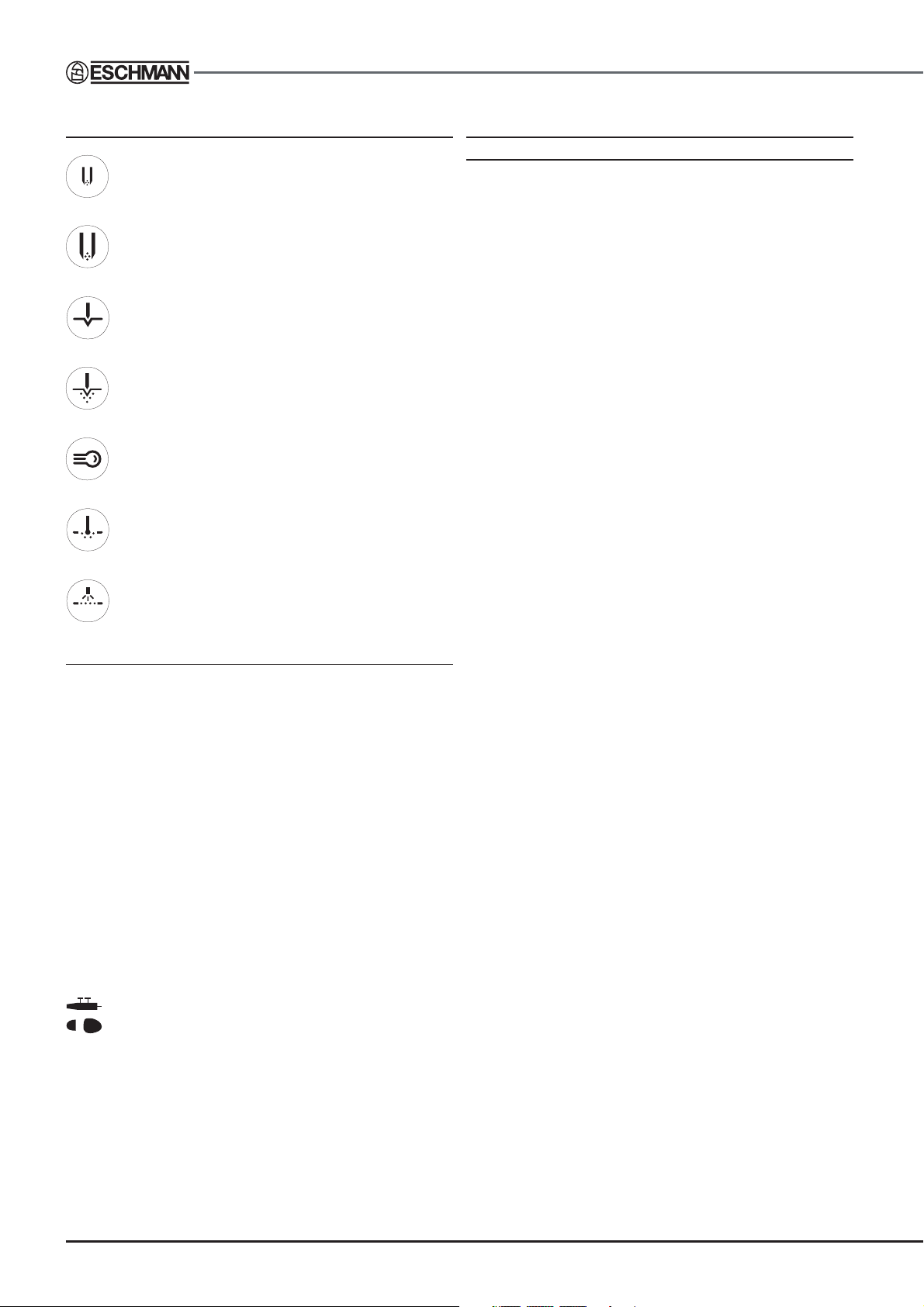
BUTTON SYMBOLS
ENVIRONMENTAL CONDITIONS
FOR TRANSPORT AND STORAGE
Press to select bipolar - micro range
Press to select bipolar - macro range
Press to select monopolar - cut
Press to select monopolar - blend
Press to select monopolar - specialist cut
Press to select monopolar - pinpoint coag.
Press to select monopolar - spray coag.
Ambient temperature range:
-30°C to +50°C
Relative humidity range:
30-90% RH non-condensing
Atmospheric pressure range:
1060hPa down to 690hPa
ALARM SYMBOLS
PCM - Indicates the ‘Plate continuity monitor’ alarm has
been activated.
PAM - Indicates the ‘Plate attachment monitor’ alarm
has been activated.
PEM - Indicates the ‘Patient earth monitor’ alarm has
been activated.
PVM - Indicates the ‘Plate voltage monitor’ alarm has
been activated.
EPM - Indicates the ‘Excess power monitor’ alarm has
been activated.
- Indicates the ‘Multiple activation’ alarm has been
activated.
! - Indicates an internal fault has been detected (see section
5, Alarm conditions, in the ‘Instructions for Use’, for details).
P8/44 E-SM44h
Page 9

3.0 SAFETY NOTES & ALARMS
TD830TD830
TD830
TD830TD830
ELECTROSURGICAL UNIT
Attention to the following points is necessary
in order to reduce the risk of accidental burns
during the use of this electrosurgical unit. Other
safety notes and warnings are also given within
the text of this manual and these should be
noted before using this electrosurgical unit.
DO:
♦ Use only Eschmann accessories, in particular active
and plate electrodes and cables which should
preferably be no more than 3 metres in length. All
Eschmann accessories are rated above the
corresponding maximum peak output voltage of this
electrosurgical unit (see graphs in section 5). For
reference Eschmann accessories can be used safely
at the following h.f. peak voltages:
Bipolar active - 400 V peak
Monopolar active - 4000 V peak
Monopolar plate electrode - 2250 V peak
♦ Use bipolar techniques in preference to monopolar,
whenever possible. For surgical procedures on parts
of the body having a relatively small cross-sectional
area, the use of bipolar techniques may be desirable
to avoid unwanted coagulation.
♦ Seek approved qualified advice (e.g. cardiology
department) before using this electrosurgical unit on
patients with implanted pacemakers or other active
implants to avoid interference or damage to the implant.
Monitor such patients carefully.
♦ Set power output controls to the minimum setting
before use and select the minimum power setting to
achieve the desired effect.
♦ Check all cables and accessories routinely before
use. In particular, electrode cables and endoscopically
used accessories for possible damage to the insulation.
♦ Ensure the entire area of the plate electrode is reliably
attached to the patient’s body and as close to the
operating field as possible.
♦ Store temporarily unused active electrodes such that
they are isolated from the patient [e.g. use a quiver
(REF 83-186-38) to hold active accessories when not
in use].
DO NOT:
♦ Do not use uninsulated forceps, monopolar or bipolar.
♦ Do not place monitoring electrodes close to the
operating site. When high frequency surgical
equipment (i.e. electrosurgical equip-ment) and
physiological monitoring equip-ment are used
simultaneously on the same patient, any monitoring
electrodes should be placed as far as possible from
the surgical electrodes. Needle monitoring electrodes
are not recommended. In all cases, monitoring
systems incorporating high frequency current limiting
devices are recommended.
♦ Do not allow active cables to drape across or contact
the patient's body or contact the cables or leads of
other equipment.
♦ Do not use flammable anaesthetics, flammable
solvents or oxidizing gases such as nitrous oxide
(N2O) or oxygen if the surgical procedure is carried
out in the region of the thorax or head, unless these
agents are sucked away.
♦ Do not allow the patient's body to touch conductive
objects. The patient should not come into contact with
metal parts which are earthed or which have an
appreciable capacitance to earth, e.g. operation table,
supports, etc. The use of antistatic sheeting is
recommended for this purpose.
♦ Do not use hook type active cables (with or without
adapters designed for use with hook type cables) use
4 mm or 8 mm plug type active cables.
♦ Do not reuse disposable plate electrodes.
♦ Do not rely solely on surgical gloves to provide
insulation.
♦ Do not allow ‘skin-to-skin’ contact (e.g. between the
arms and body of the patient), this can be avoided, for
example by the insertion of adequate dry gauze.
E-SM44h P9/44
Page 10

Attention to the following points will prolong
the life and efficiency of your
electrosurgical unit and will help to avoid the
risk of accidents, or damage:
DO:
♦ Switch off and disconnect from the mains electrical
supply prior to cleaning the equipment and when it is
not in use.
♦ Grasp the connector(s) not the cable when connecting
and disconnecting cables and leads from the
equipment.
♦ Contact the hospital electronics engineer or Eschmann
After Sales Service Department if the equipment fails
to function after checking.
♦ Ensure the equipment is serviced regularly (at least
every six months). Contact Eschmann After Sales
Service Department for details.
DO NOT:
♦ Use a faulty unit as failure could result in an unintended
increase of output power.
♦ Service this equipment unless you are suitably qualified
to do so.
Alarm Circuits
3.1 The unit has several alarm circuits as detailed in
the following sections.
Plate Continuity Monitor (PCM).
3.2 Ensures that the unit cannot be used in the
monopolar mode with an electrically defective plate
electrode or cable. It does not monitor the contact between
the plate electrode and the patient’s body. It is reset
automatically when a satisfactory plate electrode and cable
are connected to the unit.
Patient Earth Monitor (PEM).
3.5 The PEM circuit detects a low impedance path
between the patient and earth. It also reduces the chances
of secondary contact electrosurgical burns. The circuit
detects earth contact paths while the plate electrode is
attached to the patient and the unit, when a monopolar
fingerswitch or footswitch is pressed, but before the
monopolar output is activated. If such an earth path is
present, the alarm will operate until the path has been
removed and the unit reset by reactivating a pressed
monopolar footswitch or fingerswitch.
Plate Voltage Monitor (PVM).
3.6 Is designed to prevent dangerous electrosurgical
voltages appearing on the patient’s body. Such voltages
could occur because of insulation faults in the active circuit
or because the active electrode is in contact with an earthed
object and could cause burns at points of contact between
the patient and conductive objects. This alarm will operate
when monopolar output power is ‘on’ and the fingerswitch
or footswitch is operated. This monitor will not detect a poor
contact between the plate electrode and the patient. Note:
Under specific electrical conditions, with the plate electrode
completely detached from the patient, the PVM could
alarm.
Multiple Activation Alarm.
3.7 Operates if more than one fingerswitch or footswitch
is pressed at the same time in a given user section (i.e.
monopolar USER 1 or USER 2 or bipolar). It will
automatically be reset when ALL activations have been
released. This alarm will also operate if a footswitch or
fingerswitch is being activated when the unit is switched
‘on’. (Note: This could indicate a damaged accessory locked
in the ‘on’ position).
Internal error alarm
3.8 Operates if an internal fault arises such as power
being detected when not enabled by a footswitch or
fingerswitch.
Plate Attachment Monitor (PAM).
3.3 Ensures that the unit cannot be used in the
monopolar mode if a divided plate electrode is attached to
the patient’s body incorrectly. Applies only when a divided
plate electrode is used and will not operate if monopolar is
switched ‘off’ by the monopolar standby selection button.
Excess Power Monitor (EPM).
3.4 The unit monitors its output power in monopolar and
bipolar modes, compares this with the maximum allowed
power under single fault conditions and alarms, disabling
output, if the delivered power exceeds the allowed value
by more than a certain margin.
P10/44 E-SM44h
Page 11

TD830TD830
TD830
TD830TD830
ELECTROSURGICAL UNIT
4.0 INTRODUCTION
GENERAL
Note: For numbers in brackets refer to Fig. 1.
4.1 The TD830 electrosurgical unit provides two outputs
both for high power monopolar cut and coag (on a first
come first served basis), together with a separate output
for bipolar coag. Bipolar coag output is available
simultaneously with either monopolar output. The unit
incorporates touch button controls, seven segment LED
(light emitting diode) displays and LED visual indicators.
4.2 The digital displays can show two scale modes, one
shows the
shows a numerical value up to 10 (the latter is only
displayed whilst digital display range selection toggle
button (35) is held pressed).
Note: The power delivered depends on the resistance
between the active electrode and the plate electrode (or
between the tips of bipolar forceps) at the time the power
is applied. This resistance can vary widely and many times
per second during the application of h.f. output.
4.3 The unit incorporates several alarm code indicators
as detailed in the Technical Data section. Innovative safety
features include a divided plate electrode monitoring
system called the Plate Attachment Monitor (PAM) as well
as the standard Eschmann Plate Voltage Monitor (PVM),
Patient Earth Monitor (PEM) , and Plate Continuity Monitor
(PCM). An Excess Power Monitor (EPM) and a Multiple
activation alarm are also included. A high frequency
leakage control circuit is included in the monopolar mode.
4.4 Within this manual the terms USER 1 and USER 2 are
used to distinguish between the two monopolar outputs.
The bipolar output is fully independent of the monopolar
output and can be considered as USER 3.
OPERATING MODES / DISPLAY OPTION
Monopolar mode
4.5 The monopolar operating mode offers a choice of
fingerswitch or footswitch control of ‘cut’ or ‘coagulation’
outputs for USER 1. Fingerswitch operation utilises the
Eschmann two-button fingerswitch whilst footswitch control
requires the use of an active electrode handle in conjunction
with one of a range of electrical footswitches.
Bipolar mode
4.6 Bipolar coag is an efficient method of effecting
haemostasis, and closure of vessels such as Fallopian tubes.
It is extremely safe to use, as the main current path is
between the tips of the bipolar forceps and the tissue held
between them is directly in view of the surgeon at all times.
4.7 A plate electrode is not required and safety is
increased even further as two power range outputs are
available allowing precise setting of the power output.
4.8 The bipolar mode of operation offers a choice of
footswitch, electrical or pneumatic.
typical
power available in watts the second
Monopolar standby mode
4.9 The unit can be switched into monopolar standby mode,
in which only bipolar power is available, using monopolar standby
selection button (32). This button is a toggle switch, each press
of the button will turn monopolar mode ‘on’ (if ‘off ’) or ‘off ’ (if ‘on’).
This button (32) can be considered as an ‘on/off’ switch for
monopolar, the advantage being that if only bipolar outputs are
required and monopolar standby mode is selected, no plate
electrode needs to be connected to the unit. (If monopolar
standby mode is not selected for ‘bipolar use only’ and a patient
plate electrode is not connected to the unit the PAM alarm or
PCM alarm will activate). The unit is in monopolar standby mode
when only the digital display for bipolar can be seen illuminated.
Digital display options
4.10 The digital displays normally show the
available in watts. The digital displays can also show a
numerical value up to 10 (maximum). To display the power
setting as a numerical value up to 10 press and hold the
digital display range selection button (35). The display will
revert to the normal setting (and display the
available in watts) when the button is released.
(
* typical power
delivered over a range of load resistances. It is less than
the power delivered to the rated load for maximum power.)
is an indication of the average power
typical power*
typical power*
ACCESSORIES
4.11 The equipment is designed to be used with the
Eschmann range of active, plate and bipolar cables. The front
panel is colour coded, PALE BLUE for bipolar, YELLOW for
monopolar cut, blend and specialist cut, and BLUE for monopolar
coag. For a list of all accessories see the ‘Instructions for use’.
ASSOCIATED PUBLICATIONS
4.12 This manual contains service and maintenance
instructions for user servicable parts (PCBs are deemed
to be none user serviceable) and an illustrated parts list.
For detailed user instructions refer to the TD830
Instructions for Use, E-IM44 (part number 698257).
EQUIPMENT CERTIFICATION
4.13 The electrosurgical unit fully complies with the major
international safety standards (see Technical Data).
(Note: Tested at 230V).
CAUTION
This electrosurgical unit is to be operated
by medically qualified personnel only.
SERVICING
4.14 It is recommended that electrosurgical safety checks
and routine servicing are carried out at regular intervals
(every six months) and only by Eschmann trained
personnel or Eschmann trained hospital engineers,
otherwise the warranty could be infringed.
4.15 Read the information given in this manual carefully
before using, cleaning, sterilizing, or servicing the
electrosurgical unit.
E-SM44h P11/44
Page 12

1 Power output control, BIPOLAR
2 MICRO BIPOLAR selected, indicator (green LED)
3 Touch button, MICRO BIPOLAR
4 MACRO BIPOLAR selected, indicator (green LED)
5 Touch button, MACRO BIPOLAR
6 BIPOLAR digital power display (green seven segment LEDs)
7 BIPOLAR, power activated indicator (blue LED)
8 MONOPOLAR CUT digital power display (green seven segment LEDs)
9 MONOPOLAR CUT, power activated indicator (yellow LED)
10 MONOPOLAR (normal cut) selected, indicator (green LED)
11 Touch button MONOPOLAR (normal cut)
12 MONOPOLAR (blend) selected, indicator (green LED)
13 Touch button MONOPOLAR (blend)
14 Power output control, MONOPOLAR (cut)
15 Touch button MONOPOLAR (specialist cut)
16 MONOPOLAR (specialist cut) selected, indicator (green LED)
17 MONOPOLAR COAGULATION (pinpoint) selected, indicator (green LED)
18 MONOPOLAR COAGULATION (spray) selected, indicator (bright green LED)
19 Touch button MONOPOLAR COAGULATION (pinpoint)
20 Touch button MONOPOLAR COAGULATION (spray)
21 Power output control MONOPOLAR COAGULATION
22 MONOPOLAR COAGULATION, power activated indicator (blue LED)
23 MONOPOLAR COAGULATION digital power display (green seven segment LEDs)
24 8mm active electrode socket USER 1 only (footswitch activation only) - red
25 Fingerswitch sockets (for use with active electrode socket 26) - black
26 4mm active electrode socket USER 1 (footswitch or fingerswitch activation) - red
27 Fingerswitch sockets (for use with active electrode socket 28) - black
28 4mm active electrode socket USER 2 (fingerswitch activation only ) - red
29 ‘S’ (scope) connector socket (for use with flexible endoscopes)
30 Plate electrode connector socket - black
31 Bipolar output socket - white
32 Monopolar standby selection button (monopolar ‘on/off’ toggle button)
33 Running tone volume control
34 Potential equalization point (see Technical Data section)
35 Digital display range selection button (display in watts if not held pressed)
36 Bipolar pneumatic (white) footswitch socket
37 Bipolar electric (white) footswitch socket
38 Sockets for monopolar footswitches (blue, yellow or combination blue and yellow)
39 Serial number plate
40 Mains cable connection socket
41 Mains fuses (see technical data)
42 Mains power on/off control (with internal green lamp)
A1 - PCM alarm activated LED A5 - EPM alarm activated LED
A2 - PAM alarm activated LED A6 - MULTIPLE ACTIVATION alarm LED
A3 - PEM alarm activated LED A7 - Internal error alarm activated LED
A4 - PVM alarm activated LED
All alarms are accompanied by an audible two tone warning and the activated digital displays will flash (i.e. if in
monopolar standby mode, only the bipolar digital display will flash).
Key to Figure 1
P12/44 E-SM44h
Page 13

TD830TD830
TD830
TD830TD830
ELECTROSURGICAL UNIT
Figure 1 - Part identification
E-SM44h P13/44
Page 14

5.0 DESCRIPTION
CONSTRUCTION (See Fig. 6)
5.1 The TD830 Electrosurgical unit is made of four
principle electronic sub assemblies as listed below :
♦ Front panel
♦ Rear panel
♦ Mains transformer and rectification assembly
♦ Main printed circuit board assembly
5.2 The front panel includes the display and control
board, operator controls, finger switch inputs and the RF
outputs.
5.3 The rear panel includes the foot switch interface,
mains input switch and lamp, display control switch and
the tone volume control.
5.4 The mains transformer and rectification assembly,
fitted inside on the right hand side (when viewed from the
front) on a metal base plate, provides mains isolation and
voltage conversion, protection and a 180V d.c. rectified
power feed to the RF power section.
5.5 The main printed circuit board assembly, positioned
within the unit on the left hand side (when viewed from the
front) fitted on a metal base plate, controls and supplies all
the RF outputs.
SUB ASSEMBLY DESCRIPTIONS
(see Fig.6)
Front panel
5.6 The front panel assembly comprises a main display
and control board (see 5.7) with its buttons, LEDs and three
7 segment displays (Bipolar, Monopolar Cut and Monopolar
Coag). There are three Potentiometer controls for setting
RF power levels (Bipolar, Monopolar Cut and Monopolar
Coag), a Bovie sensing microswitch and pivot assembly.
The panel also includes the connectors and cabling for
the four RF outputs (Plate, Bipolar, Mono1, Mono 2 and
Bovie). There are two current sense toroids, the larger for
leakage sensing and the smaller for output current sensing.
5.7 The main display and control board performs the
following functions:-
i Uses the front panel control knobs to set the
maximum allowable power for each mode.
ii Allows mode selection (IC4) and display (IC8)
through 8 front panel buttons and associated LEDs
(Bipolar Macro or Micro; Specialist Cut, Normal Cut
or Blend; Pinpoint Coag. or Spray Coag. and
Standby).
iii Provides the controls for all RF outputs through a
64-way ribbon cable (J6).
iv Provides alarm control and logic (IC6) and
illuminates an LED to indicate the type of Alarm.
v Provides three digital 7 segment displays (IC13, IC1,
IC5) for power levels of Bipolar, Cut and Coag.
vi Provides all logic for foot and finger switch controls
(IC12, IC11).
vii Provides Battery back up of the last mode selection
before switching off (BATT1, IC2,IC4).
viii Uses the Bovie sense microswitch to enable the RF
routing to the Bovi RF output for Mono user 1.
ix Provides CMOS (IC9, IC10) and open collector
drives (IC7) for the main printed circuit board
assembly.
x Provides control signals as follows:
SPEC BLEND
CUT SPRAY
CUTMODE COAGMODE
MONENABLE BIPENABLE
BIP_LOW MONORELAY1_SEL
PEM_RELAY MONORELAY2_SEL
MONORELAYBOVI_SEL
xi Provides Tone Generator controls as follows:
BLEEP_TONE CUT_TONE
COAG_TONE BIPOLAR_TONE
ALARM_TONE
xii Receives Foot and Finger switch signals as follows:
FINGERCUT_1 FINGERCOAG_1
FINGERCUT_2 FINGERCOAG_2
FOOTCUT_1 FOOTCOAG_1
FOOTAIR_BIP FOOTELEC_BIP
xiii Receives alarm signals as follows:
PVM PAM
PCM PEM
MONOPWRDET BIP_EXCESS
MONO_EXCESS
ALARM SQUARE (from Tone generator).
5.8 The one set up potentiometer (VR1) is factory set
at manufacture and does not need resetting during the life
of the product.
Rear panel (see Fig. 6)
5.9 The rear panel provides connection to the mains
a.c. supply via an IEC inlet (which includes fuses, switch
and integral green lamp), also fitted to the rear panel are:
i A volume control potentiometer.
ii A range switch.
iii Two Monopolar footswitch circular multi-pin
connectors
iv An electrical Bipolar footswitch connector.
v A pneumatic Bipolar footswitch connector.
vi The Rating and Serial Number plate.
P14/44 E-SM44h
Page 15

TD830TD830
TD830
TD830TD830
ELECTROSURGICAL UNIT
vii A 15 way interconnect cable (from the footswitches,
range switch, volume control and the Mother board
of the main PCB Assembly).
viii Mains interconnect to the Mains Transformer
Assembly.
ix Safety earth strap for the rear panel.
5.10 The two Monopolar footswitch circular multi-pin
connectors are wired together so that either of two
footswitches can enable RF power.
5.11 The range switch selects either normal power levels
or a 0–10 range when pressed (see the ‘Instructions for
Use’ supplied with the unit).
Mains transformer & rectification assembly
(see Fig.6)
5.12 The mains transformer and rectification assembly
comprises a 50/60Hz mains transformer with several
secondaries providing the following:
i 50 V a.c. (Bipolar low/Micro) and 75V a.c. (Bipolar
high/Macro) for the Bipolar Output.
ii 15 V a.c. (rms) for the +15V output supply from the
PSU board.
iii 15V a.c. (rms) for the -15V output supply from the
PSU board.
iv 5V a.c. (rms) for the +5V output supply from the
PSU board.
5.13 The above a.c. supplies are connected to the
motherboard at SK12 through a 9-way cable and connector
from the Transformer PCB. They are short circuit protected
by thermistors, which recover when an overload is
removed.
5.14 Another secondary provides the feed for a rectifier
whose output from the PCB is through a 2-wire (P1)
connection to a large reservoir capacitor fitted near the
transformer. This provides a 180V d.c. power feed to the
Monopolar outputs which are supplied from the capacitor
to the mother board at SK13. This secondary is protected
by an internal over temperature sensor. Fitted to the
discharge resistor is a capacitor so that energy is drained
away to make the capacitor safe when the mains power is
switched off.
5.15 The mains input voltage is factory selected by links
on the input connector P10.
Main printed circuit board assembly (see Fig. 6)
5.16 The main printed circuit board assembly comprises
a motherboard assembly (Part No 715205) which supports
the other boards that make up the main printed circuit board
assembly. The motherboard provides the inter-board
connections and power feeds to the other boards of this
assembly and is positioned horizontally under them. The
other boards are listed below and are detailed in their own
sections:
♦ Patient Interface (Active) PCB
♦ Patient Interface (Plate) PCB
♦ Tone Generator PCB
♦ PSU PCB
♦ Bipolar PCB
♦ Crowbar PCB
♦ PCM DC regulator PCB
♦ Monopolar Power Amplifier PCB
comprising the:
♦ Spray and Monopolar PCB
which includes the:
♦ Relay PCB
♦ Logic and pulse PCB
5.17 The motherboard receives power from the mains
transformer (SK12), 180V d.c. power (SK13), control from
the front panel (SK2) and the rear panel (SK14) and current
(SK3) and leakage sensor (SK4) feedback. The rear panel
footswitch circuitry has an isolated supply (IC3) and
interface (IC’s 1 and 2) providing 250V AC isolation.
5.18 Capacitors are fitted to the motherboard (C1-2, C47, C10, C13-14, C15 A-I) to protect against RF interference.
Patient Interface (Active) PCB (Part No 715201)
5.19 This board is fitted in the front slot nearest the display
board (SK3 of the Mother board). It receives a single
Monopolar Active RF power feed on PL4-2.
5.20 It also receives control signals (MONORELAY_1,
MONORELAY_2, MONORELAY_BOVI) and returns finger
switch signals (FINGERCOAG_1, FINGERCUT_1,
FINGERCOAG_2 and FINGERCUT_2) to the display
board through the motherboard and the 64-way ribbon
connector.
5.21 The Monopolar RF feed is routed by HV RF relays
to one of three outputs: Mono1 (connector PL1 through
Relay RL3), Mono2 (PL2, RL1) or Bovi (PL3, RL2). This is
done under control from the display board (signal names
MONORELAY_1, MONORELAY_2, MONORELAY_BOVI).
5.22 In addition to the RF power output feed to Monopolar
1 there are two finger switch control lines which allow
activation of Cut or Coag RF power (PL1-2, PL1-1). These
lines are supplied with a sensing drive signal (IC1, TR1,
L1) through a transformer (TX10) and return to two optoisolators (O11, O12). When a fingerswitch is pressed that
line causes current to flow through the opto-isolator and
activate the control signal from the PIA active board to the
display board (signal names FINGERCOAG_1,
FINGERCUT_1).
5.23 The same applies to Monopolar 2 (PL2-3, 4). (Optoisolators O13, O14, signal names FINGERCOAG_2 and
FINGERCUT_2).
5.24 Fingerswitch signals (FINGERCUT/COAG_1,_2)
are returned to the Display board through the motherboard
and the 64-way ribbon connector.
E-SM44h P15/44
Page 16

Patient Interface (Plate) PCB (Part No 715203)
5.25 This board is fitted in the second slot from the front
(SK4 of the Mother board). It receives a single Monopolar
Plate RF power feed on PL2-4. This is then fed into two
plate outputs via HV RF capacitors C1 and C6 (PL2 -2,3).
These go to the front panel Plate RF output along with a
third plate wire (PL2 -1) which becomes shorted to PL2-2
when a plate connector is fitted.
5.26 It also receives a control signal (PEM_RELAY) and
returns alarm signals (PEM, PCM, PAM, PVM) to the
display board through the motherboard and the 64-way
interconnecting ribbon cable.
5.27 When a plate connector is fitted terminals PL2-1 and
PL2-2 are shorted together. This turns on an Oscillator
(TR1, TR2, TX3) which is detected by IC4B and RV5 and
supplies a PCM ‘OK’ signal (low) to the display board.
Conversely if the plate connector is not fitted a PCM alarm
(high) is sent to the Display board. If the plate is not fitted
correctly to the patient PL2-3 is isolated from PL2-2 at the
oscillator frequency. This is sensed (IC4A, RV4) and sends
a PAM (plate attached alarm) to the display board which
gives the alarm.
5.28 The plate voltage is monitored through PL2-1, C10,
C13, R 10-14. This voltage is then sensed (IC3, RV2, D15,
C44) and, if high, sends a PVM (high) signal to the display
board.
5.29 A sample of the impedance between the plate and
earth (at the units mains inlet) is carried out during a 2040msec sample just before supplying any RF output power.
This is achieved using relay RL1, Oscillator IC1F, TR6, L2,
C16 and TX2. If the PEM impedance is below 200W as
sensed by IC2, RV3, D14 and R32 an alarm is sent to the
Display board (signal name PEM). Oscillator TR5, TX4,
C18 provides the means to supply an isolated DC rail on
the secondary of TX4 ,D3, D4.
Tone Generator PCB (Part No 715273)
5.33 The volume of Cut, Coag, and Bipolar tones and
the ‘bleep’ are controllable by the potentiometer on the rear
panel. This is fed through the motherboard to the Tone
Generator.
PSU PCB (Part No 732061)
5.34 This board is fitted in the fourth slot from the front
(SK6 of the Mother board). It receives AC power from the
Mains transformer through SK12 and SK6 on the
motherboard and provides +15V (SK6 A-C2), +5V (SK6
A-C4) and –15V (SK6 A-C6) for all the other boards in the
unit. These rails are fed through the Mother board.
Note: The +15V regulator on this board does get hot.
Bipolar PCB (Part No 715222)
5.35 This board is fitted in the fifth slot from the front (SK7
of the Mother board). It receives AC power from the mains
transformer through SK12 and SK7 on the motherboard
and provides a Bipolar RF output on PL1 which is
connected to the front panel through a 2 wire RF cable.
5.36 It receives control signals (BIP_EN, BIP_LOW) from
the display board through the motherboard and the 64way ribbon cable. It also receives a power level control
(BIPC-, BIPC+) and excess power threshold (BIP_LEVEL)
from the front panel Bipolar control knob.
5.37 The Bipolar control knob is composed of two ganged
potentiometers one of which (BIPC 100KΩ) provides power
control and is routed through the display board 64-way
ribbon cable and motherboard to the bipolar board. The
other (BIP_LEVEL) is buffered on the display board and
fed to the Bipolar through the 64-way ribbon cable and
motherboard.
5.38 The Bipolar board has a Push Pull RF output driver
(IC6, TR7, TR8) which feeds RF power through a
transformer (TR6). The transformer provides isolation and
voltage step up. Control of power is achieved by controlling
the output duty cycle (IC5, IC8).
5.30 This board is fitted in the third slot from the front
(SK5 of the Mother board). It receives control signals
(CUTTONE, COAGTONE, BIPTONE, BLEEP, ALARM)
from and returns ALARM SQUARE to the display board
through the motherboard and 64-way connector.
5.31 The Tone Generator has a speaker (LS1) which
gives the following tones when activated:
♦ 950Hz for Monopolar Cut.
♦ 800Hz for Monopolar Coag
♦ 730Hz for Bipolar
Note: If both Bipolar and Monopolar modes are active it is
the first tone which is retained until it is released.
5.32 When a button is pressed a ‘bleep’ is given and when
an alarm is given a loud two-tone sound is provided. Cut,
Coag and Bipolar Tones are provided by IC1 and fed
through IC2 and speaker driver IC4. Alarm and two tone
control is provided by IC3 and IC6.
5.39 IC10 provides the fundamental oscillator, which also
limits the on time of each FET driver and through IC9, forces
the drive for FET’s TR7 and TR8 to be asynchronous.
5.40 The Transformer primary voltage (IC3C,
VOLTAGE_A/B) is combined with the output current (TR5,
CURRENT+/-) to provide the output power level (IC1, R3,
C10). This is then compared (IC2B) with the front panel
displayed power level (BIP_LEVEL , IC3A,B) and if the
output power exceeds a tolerance from the displayed power
level (VR3,4) an alarm signal (IC7, PL3-24, BIP_EXCESS)
is sent to the display board and the RF power is immediately
removed (IC8B, IC8A).
5.41 Current limit is provided by IC3D, TR2 and set by
VR2.
Crowbar PCB (Part No 732059)
5.42 This board is fitted in SK8 between the Bipolar board
in SK7 and the PCM board in SK9. It is a small board
P16/44 E-SM44h
Page 17

TD830TD830
TD830
TD830TD830
ELECTROSURGICAL UNIT
secured near the Mother board. It provides over voltage
protection for the Monopolar inverter d.c. power feed.
5.43 In normal operation the 180V d.c. is supplied by the
transformer assembly and reservoir capacitor and fed
through SK13 on the Mother board and on to SK8-1,2 on
the Crowbar at which point it is passed through a safety
fuse (5A FF) and on to the PCM board back through SK84,5.
5.44 If the PCM board fails such that it places too many
volts (140V) into the inverter, the Crowbar circuit detects
this and turns on a high power transistor to load the 180V
power feed to the PCM. This diverts current away from the
failed PCM board until the fuse on the Crowbar board blows
and isolates the 180V source.
5.45 The 5A fuse also protects against FET failures within
the output inverter or any other form of short circuit within
the PCM, which loads the High Voltage power rail.
PCM (Power control Mono) DC regulator PCB
(Part No 715272).
5.46 This board is fitted in the second slot from the back
(SK9 of the motherboard). It provides a regulated d.c.
supply to the Monopolar RF inverter.
5.47 180V d.c. power is provided from the Crowbar
protection circuit through the motherboard.
5.48 Control signals (MON_ENABLE, CUT_MODE,
COAG_MODE, SPRAY, CUT, BLEND, SPEC_CUT) are
received from the display board along with the power level
(0-15V control from the front panel Cut or Coag control
knobs).
5.49 A Mono-power-detect signal is returned to the
display board (D5, R10, R11) through the motherboard
(SK9 A22) and the 64-way ribbon cable. This is a Logic
level, which is high when the output of the regulator is above
5V (i.e. on). If this signal is high when power was not
requested the display board and tone generator give an
internal fault (!) alarm.
5.50 This board uses a step down, pulse width modulated
voltage regulator to provide a variable output voltage of 5–
120V from the 180V supply. Switching FET’s (TR3, TR4)
are driven by IC1 from IC8 and controlled by IC7 to force
the output voltage (A30, C30) to be proportional (R9, R16,
R30) to the dc control level on IC7 pin 2. Output power is
proportional to the square of the output RF voltage and so
it is important to provide a regulated output proportional to
the square root of the front panel setting to have a linear
relationship between control setting and final output power.
5.51 The control level on IC7 pin 2 is derived from the
front panel Coag or Cut control knob. This is sent by the
display board according to whether a Cut or Coag switch
has been activated and passed to the PCM board through
the 64-way ribbon cable connector and motherboard.
according to the mode of operation of the unit (Spray/Blend/
Cut etc.). When using Specialist cut mode an initial power
boost (10%) (R22, IC3, IC6B) is provided for a period of
about 300msec (C17 ,VR1).
5.53 The input current to the PCM board is monitored
(R1A-E) and sensed (TR1) to limit (IC2A, IC3A) the input
current drawn by the PCM card to less than 8Amps in case
of a fault on the regulator or on the subsequent RF inverter.
5.54 An output fuse (5A FF) is also used to protect the
output stage of the PCM card.
Monopolar Power Amplifier PCB
(Part No 715275)
5.56 This assembly is made up of three boards and fitted
into the slot nearest the rear panel (motherboard SK11)
the three boards are:
Spray and Monopolar PCB
Relay PCB
Logic and Pulse PCB
These boards detailed in the following sections are not
available as separate, individual boards.
Spray and Monopolar PCB
5.57 The Spray and Monopolar board is a large board
and carries two other circuit boards, the relay PCB and
the Logic and Pulse PCB. Its function is to take the
regulated 5–120V d.c. supply (PL2) and turn this into a
high frequency high voltage RF source.
5.58 The pulsed RF output for Cut, Blend, Pinpoint and
Specialist Cut is provided by switching (TR14, 16, 18, 19)
the supply, alternately through an RF output transformer
(T1).
5.59 The high voltage low duty cycle Spray output is
provided by releasing (TR4-11) energy, stored in an
inductor (L1) through the output transformer (T1) and
resonating capacitors (C8A-E).
5.60 The regulated d.c. is fed to this board from the PCM
regulator board through the motherboard (SK9, SK10) and
a 2 wire interconnecting cable to PL2.
5.61 The controls are received through SK11 and passed
to the Logic and Pulse board (SK3). Drive waveforms for
the switching FET’s (TR14 etc.) are provided by the Logic
and pulse board, buffered and amplified (IC9, 10, 15, 16
and IC14 for Spray) on the spray and monopolar board.
5.62 The RF Output current is sensed by a toroid (MTG
24-27) and fed back to the logic and pulse board for current
limiting and control (SK6).
Relay PCB
5.63 The Relay board is a small board holding 3 relays
(RLA-C) mounted on the Spray and Monopolar board.
5.52 This control/power level is received by the PCM
board (A12), scaled (R18, R19), buffered and square rooted
(IC4A), and further scaled (R21, R24-R28, IC2, IC3)
5.64 Relay ‘A’ passes the energy pulse from the Spray
circuit to the output transformer in Spray mode only. In all
other modes this relay is off and isolated.
E-SM44h P17/44
Page 18

5.65 Relays ‘B’ and ‘C’ pass the push pull power drive
from the switching FET’s to the output transformer in all
modes accept Spray.
5.66 These relays are special high voltage devices.
Logic and Pulse PCB
5.67 The Logic and pulse board assembly is fitted with
surface mounted components and is mounted on the spray
and monopolar board assembly. This board provides all
the control and interfacing for the Monopolar output. It has
the RF oscillators (IC8, IC9) for Cut modes and Pinpoint
and the RF oscillator (IC11) for Spray.
5.68 It receives control signals (CUT, SPEC, BLEND,
CUTMODE, COAGMODE, MONENABLE) from the
Display board and sends an excess power alarm signal
back to the display (via the Monopolar Power Amplifier
Assembly and Motherboard and 64-way ribbon cable). All
inverter pulse drive waveforms (PL4 -15, 16, 19, 20) for
the Spray and Monopolar board are supplied by this board.
5.69 It receives Voltage feedback (IC24B, TP33) from the
Primary of the Monopolar output transformer and current
feedback (IC 24A, TP25) from the Current Sense coil which
is fitted near the front panel. These two feedbacks are used
to measure the output power of the unit (IC18) which is
compared (IC5B) with the front panel setting (PL4-21,
IC12B, TP19).
POWER OUTPUT GRAPHS
5.75 The power output graphs (shown on the following
pages) have been optimized to provide effective cutting
and coagulation over the wide range of tissue impedances
that may be encountered. The low impedance region of
the profiles, below the normal operating range, is controlled
by a current limiting circuit designed to protect the
equipment and accessories connected to it. All
measurements are made at 20°C (68°F).
5.70 If the output power exceeds the set power level by
an excessive margin an alarm is given (PL4-22, IC12C)
and RF power is removed (IC22A, IC21B, C) by stopping
the RF inverter clocks.
5.71 This board also receives (PL4-10, 11, IC23, IC13B,
IC14A) the leakage current feedback from the Leakage
sensor near the front panel. This leakage current is
compared (IC14D) with a 75mA target level set up by VR20.
If the leakage current exceeds the 75mA threshold, the
output power will be reduced (IC19A, IC16A, IC15B, IC19D,
IC22A) to limit it to 75mA.
5.72 This board also delays the control of leakage current
to allow full power at the beginning of a cut. Leakage control
is disabled when the Monopolar output is loaded by less
than a set point, see table 2.
5.73 The load is measured (VR21, IC24C, IC14C, IC15A,
IC2, IC16B) for Spray Coag by monitoring the decay rate
of the output power after an energy pulse (IC17A). The
load measurement for all other modes is achieved by
comparing (IC14B) the output voltage (TP33) and the
output current (R112, VR22) to see if their ratio is above or
below the set point. If above, then leakage control is in
operation. If not, then leakage control is disabled.
5.74 The Relay board controls are also supplied by the
logic and pulse board (TR1, TR2, PL4, 17-18).
P18/44 E-SM44h
Page 19

MONOPOLAR CUT DIAGRAMS
TD830TD830
TD830
TD830TD830
ELECTROSURGICAL UNIT
E-SM44h P19/44
Page 20

MONOPOLAR BLEND DIAGRAMS
P20/44 E-SM44h
Page 21

ELECTROSURGICAL UNIT
MONOPOLAR SPECIALIST CUT DIAGRAMS
TD830TD830
TD830
TD830TD830
E-SM44h P21/44
Page 22

MONOPOLAR PINPOINT COAG DIAGRAMS
P22/44 E-SM44h
Page 23

ELECTROSURGICAL UNIT
MONOPOLAR SPRAY COAG DIAGRAMS
TD830TD830
TD830
TD830TD830
E-SM44h P23/44
Page 24

BIPOLAR MACRO DIAGRAMS
P24/44 E-SM44h
Page 25

BIPOLAR MICRO DIAGRAMS
TD830TD830
TD830
TD830TD830
ELECTROSURGICAL UNIT
E-SM44h P25/44
Page 26

6.0 MAINTENANCE
ROUTINE CHECK
6.1 Routine checking should be limited to external
checks of the unit, and must include all accessories and
cables. Routine checks detailed in the ‘Instructions for use’
(see Section 1, Related Technical Publications’) must be
carried out each time the unit is used.
SYSTEMS CHECK
6.2 The systems check detailed in the ‘Instructions for
use’ should be carried out before the unit is used for the
first time and after every service or maintenance procedure.
In addition the systems check should involve verification
of the performance of the unit relative to the information
under Performance Checks (sections 6.27 through to 6.34).
This should be done at least every six months. Also see
the section ‘Short circuit test’.
CLEANING DISINFECTION AND CARE
6.3 Consult the ‘Instructions for use’ for cleaning
disinfection and care instructions.
ACCESS FOR MAINTENANCE
Front panel
6.6 To release the front panel first remove the top cover
(see 6.5) and then the two screws at the bottom rear edge
of the front panel moulding (see 18 parts list 4) and finally
remove the two screws from inside the unit (see 15 parts
list 4) that hold the front cover to the base moulding. To
finally release the front panel unplug all cables from the
internal electronics noting their locations.
Rear panel
6.7 To remove the rear panel in the easiest manner use
the sequence that follows:-
i Release the two brackets (5, parts list 1) holding
the power amplifier board (1, parts list 4) in place.
ii Release the two leads plugged into the top of the
power amplifier board and carefully remove the
power amplifier board from the unit by releasing it
from its mother board connection.
iii Unplug the lead from the back panel where it plugs
into the transformer socket and release the earth
connection from the back panel to the chassis plate.
iii Release the rear panel connection to the mother
board and then lift the rear panel up and out of its
location in the base moulding.
WARNING
When the equipment cover is removed
potentially dangerous voltages are exposed.
CAUTION
Before removing a board, disconnect plug from
socket P1 on mains transformer board (see
22, parts list 1) and wait for five minutes to allow
mains storage capacitor (12, parts list 1) to
discharge.
CAUTION
This equipment contains ‘static sensitive
devices’, during maintenance appropriate
handling precautions should be followed at all
times.
6.4 Before gaining access inside the unit switch off the
mains supply and remove the mains lead.
Top cover
6.5 To remove the top cover turn the unit over and
remove the two cover retaining screws located in the base
recesses near the two rear feet. Carefully turn the unit back
onto its feet and lift the rear of the top cover up and then
backwards releasing it from the front panel. To replace the
cover reverse this procedure.
To replace the rear panel reverse the above sequence and
check all leads have been connected.
REMOVAL AND INSTALLATION
Circuit board removal (except crowbar)
6.8 To remove any circuit board remove the top cover
as detailed in section 6.5. The large power amplifier board
is removed as detailed in 6.7 parts i and ii, all other boards
(except the crowbar board, see section 6.9) can be
removed from the mother board after removing both PCB
clamps (4, parts list 1) fitted to the top of the PCB card
guides (1, parts list 3).
Crowbar board removal
6.9 The crowbar board, situated between the Power
control (monopolar) board and the Bipolar board, can only
be removed after first removing both of these boards from
the unit. Once access has been made to the crowbar board
the retaining rivet through the bracket and crowbar board
should be removed (not the rivet through the bracket and
the mother board) see the ‘Rivet removal/replacement’
section that follows. Finally remove the crowbar board from
the mother board.
Rivet removal/replacement (crowbar board)
6.10 To remove the rivet pull up the plunger head (see 2
below) taking care not to damage rivet head, pull rivet out
from bracket (see 1 below). To replace the rivet align the
holes in board and bracket (see 1 below), place rivet into
P26/44 E-SM44h
Page 27

TD830TD830
TD830
TD830TD830
ELECTROSURGICAL UNIT
hole so that the shoulder of the rivet shaft is flush with the
outer cover face (see 2 below), press rivet plunger head
until flush with cover surface (see 3 below).
Circuit board replacement
6.11 All boards incorporate anti-confusion plug and
socket connections, otherwise replacing boards is selfevident, but ensure that any disconnected cables are
correctly connected. When replacing the crowbar board
ensure the rivet is replaced as detailed in section 6.10.
Ensure all PCB clips and clamps are replaced after
installation
SUPPLY FAULTS
6.12 When the unit is switched ‘on’, the green ‘mains’ pilot
lamp in the switch should come ‘on’. If no pilot lamps come
‘on’ check the mains fuses on the rear panel (Fig. 1 item
41). If fuses are satisfactory, check fuse in mains supply
plug and if this is satisfactory, check that electrical supply
is available.
Fuse Renewal (Fig. 1 item 41)
6.13 To fit a new fuse:
iEnsure unit is disconnected from mains electrical supply.
ii Remove fuse retainer and fuse.
iii Fit new fuse of correct type and rating (see unit back
panel).
If the fuse repeatedly fails, either when the unit is switched
‘on’ or during use, call Eschmann Equipment After Sales
Service Department (see inside front cover) or the hospital
engineer.
Alarm remedies
6.16 If the PCM circuit has been activated:
(i) Check plate electrode is connected to unit.
(ii) Check plate electrode and cable for condition, if
faulty, substitute new plate electrode and/or cable.
This procedure should normally be carried out before
plate electrode is attached to patient.
6.17 If the PAM circuit has been activated:
(i) If a divided plate cable and divided plate electrode
are being used check that the divided plate electrode
is making good contact with the patient’s body.
(ii) Check plate electrode and cable for condition, if
faulty, substitute new plate electrode and/or cable.
This procedure should normally be carried out before
plate electrode is attached to patient.
6.18 If the PEM circuit has been activated:
(i) Check for accidental direct contact between patient
and an earthed object, (drip stand or conductive part
of operation table).
(ii) If applicable disconnect suspect ECG electrodes.
Note: An activated PEM alarm will be reset by
removing the earth path and reactivating a monopolar
footswitch or fingerswitch.
6.19 If the circuit has been activated:
(i) The alarm will operate if the bipolar pneumatic
footswitch and the bipolar electrical footswitch are
pressed simultaneously. The alarm will also sound
if both the cut and coag footswitches, or if one of the
two footswitches and a fingerswitch button are
pressed simultaneously for USER 1, or if both
fingerswitch buttons are pressed for USER 1 or
USER 2. The circuit will automatically reset when
ALL activations stop from ALL switches. This is an
important safety feature and applies to any
combination of footswitch and fingerswitch.
FAULT FINDING
6.14 If the equipment malfunctions, first check
accessories and cables by substitution before doing further
checks.
6.20 If the EPM circuit has been activated:
(i) Because the EPM alarm cannot be reset by the
User, if unit EPM alarm activates as soon as output
is activated, Eschmann Equipment should be
contacted.
Alarms
6.15 All alarm conditions are indicated by an audible twotone alarm and an error indication on the front panel. The
alarm symbols are detailed in the Technical data section
with additional information in the ‘Safety notes and alarms’
section of the ‘Instructions for use’. The ‘Instructions for
use’ also provide details of alarm conditions, identification
and remedies but for ease of reference the remedies are
repeated below:
6.21 If the PVM circuit has been activated:
(i) If unit PVM alarm activates check for accidental
direct contact between the active electrode and an
earthed object.
(ii) Check that the plate electrode is correctly attached
to the patient’s body.
Note: An activated PVM alarm will automatically be reset
by releasing a depressed footswitch or fingerswitch.
If none of the above remedies stop the alarm activated, or
the (!) alarm is activated contact Eschmann Equipment
and do not use the unit.
E-SM44h P27/44
Page 28

EXTENDER BOARD (Fig. 2)
PERFORMANCE CHECKS
WARNING
When the extender board is used in the
monopolar power control position, high
voltages are exposed and extreme care must
be taken.
6.22 To facilitate testing and servicing of boards on the
mother board, Eschmann have produced a special-to-type
extender board (Part No. 711367). The board has separate
pins located below the 96-way socket, allowing easy
connection of measuring equipment.
Fig. 2 Using the extender board
General
6.26 Unless otherwise stated, errors found in the output
waveforms and the current readings measured will indicate
a fault in the unit and will probably need the attendance of
a service engineer.
Output Waveform Timings
6.27 The following equipment will be needed:
♦ Oscilloscope with timebase resolution to at least 10
nanoseconds.
♦ Current probe or inductive pick-up loop attached to
the oscilloscope.
♦ Eschmann ETS3 test set.
Note: The Eschmann ETS3 test set should be used for
routine power output checking. When set for monopolar
power output, the test load is 200 or 400 ohms and the
power output can be read directly from the outer scale of
the appropriate meter. This value can be compared with
the value derived from the relevant monopolar power graph
and should be within the limits required by EN60601-1:1990
and IEC60601-2-2:1998. For bipolar power measurement
the test load is 100 ohms.
Instructions for use, and connections are given in the test
set lid.
6.23 Three LEDs on the board indicate healthy logic
supply rails. The left hand LED indicates
-15Vd.c. and just comes ‘on’ at -14Vd.c. The centre LED
indicates +15Vd.c. and just comes ‘on’ at +14Vd.c., while
the right hand LED indicates +5Vd.c., and just comes ‘on’
at +4Vd.c.
6.24 When it is necessary to test a board, disconnect
plug from socket P1 on mains transformer board (see 22,
parts list 1) and wait for five minutes to allow capacitor (12,
parts list 1) to discharge. Disconnect/remove the board
from the mother board and replace it with the extender
board. Plug the removed board into the top of the extender
board as shown in Fig. 2. Where applicable, any
disconnected cables should be reconnected to the board
being serviced.
Note: If testing PCM pcb (item 2, parts list 4), the plug
must be reconnected to socket P1 on the mains transformer
board. (Running tones and lamps will not be enabled with
P1 disconnected).
FREQUENCY OF CALIBRATION
6.25 Calibration need only involve verification of the
performance of the unit relative to the information under
Performance Checks (sections 6.25 through 6.33). This
should be carried out at least every six months.
Do not use test sets ETS1 or ETS2 as they are not designed
for use on the TD830 Electrosurgical unit.
Preparation
6.28 Prepare the equipment as follows:
i Connect ETS3 test set to the unit with appropriate
load and meter as required by each waveform
diagram (Figs. 3, 4 and 5).
ii Connect probe, or inductive pick-up loop to the plate
connecting wire.
iii Adjust oscilloscope to give, as near as possible, the
waveforms shown in each diagram with the power
at setting 5 on the power control. Do not exceed
duty cycle of the unit or the test set.
Timing Measurements
6.29 Follow the instructions on the ETS3 test set, and
check the timing measurements given on Figs. 3 and 4
(monopolar) and Fig. 5 (bipolar) against the information
given in Table 1.
P28/44 E-SM44h
Page 29

TD830TD830
TD830
TD830TD830
ELECTROSURGICAL UNIT
Monopolar Output Current
6.30 The maximum currents into 200 ohms for the
monopolar outputs should be checked using the ETS3 test
set. The instructions for connection to the test set are on
the inside of the test set lid.
Mode Limits
Normal cut 1.06 to 1.22 A
Blend 1.10 to 1.34 A
Specialist cut 1.18 to 1.32 A
Pinpoint coag 0.77 to 0.95 A
Spray coag 0.57 to 0.69 A
If the readings for these currents are out of specification,
contact the Eschmann Equipment After Sales Service
Department.
Specialist Cut Boost Check
6.31 Set the oscilloscope timebase to 100ms per division.
Connect the oscilloscope and current probe to the plate
connecting wire on the ETS3 test set, and set the test box
for a 200 ohm load and 1.5A meter. Set the output mode
on the unit to specialist cut, and the output level to 5. Enable
the output and observe that the amplitude of the pulses is
initially increased for about 300 milliseconds before settling
to a continuous lower ‘normal’ level.
Monopolar Current Limit Check
6.32 Connect the ETS3 test set the unit to as follows:
ETS3 Socket Connect to
1 Earth (footswitch plug)
2 Plate and socket 4 on ETS3
3 Not connected
4 Socket 2 on ETS3
5 Not connected
6 Not connected
7 Active from TD830
Bipolar Output Current
6.34 The bipolar output currents should be checked using
an ETS3 test set connected as instructed for bipolar
measurements.
Mode and Power Level Limits
50W setting 10 0.63 to 0.77A
50W setting 5.5 0.46 to 0.57A
15W setting 10 0.36 to 0.44A
If any of the above readings do not come within the limits
contact Eschmann Equipment After Sales Service
Department.
ACTIVE RELAY FUNCTION TEST
6.35 It is important to carry out a check for a possible
short circuit of the relays on the active monopolar patient
interface board every six months. This test is performed
as detailed in the following sections.
6.36 Fit a 200ohm resistor and a 250mA ammeter in
series between the plate socket and the monopolar 1 active
4mm output socket. Energise in turn the other two
monopolar outputs (monopolar 2 active 4mm socket and
Bovie type active 8mm socket) in open circuit at maximum
power display level in spray coag, normal cut and specialist
cut.
6.37 Confirm that the current does not exceed 150mA in
any of these conditions. Repeat this test with the ammeter
connected to the monopolar 2 active 4mm socket and the
to the Bovie type active socket. Do not use the unit if it fails
this test.
NOTE: In order to energise the Bovie type active 8mm
socket it is necessary to insert an 8mm plug. In order to
energise the adjacent monopolar 1 active 4mm output
socket it is necessary to ensure that there is not an 8mm
plug inserted into the Bovie type active 8mm socket.
These connections connect a 100Ω load, and a 1.5A meter
across the output.
6.33 Ensure that the unit is at normal operating
temperatures and check that the currents are:
Mode Limits
Normal cut 1.11 to 1.36A
Blend 0.97 to 1.18A
Specialist cut 1.27 to 1.56A
Pinpoint coag 0.89 to 1.10A
Spray coag 0.77 to 0.94A
SET UP OVERVIEW
6.38 The information given in Table 2 gives an easy guide
for set up of the TD830 Electrosurgical unit by an Eschmann
trained engineer and cannot be used without the test criteria
or properly calibrated test equipment.
SYSTEM DIAGRAM
6.39 The system diagram is shown in Fig. 6.
E-SM44h P29/44
Page 30

Table 1 Monopolar And Bipolar Timing Measurements
Monopolar Measurement Function Figure Timing
1 Pulse width Normal cut, blend, 3A 0.90 to 0.98 µsec
pinpoint coag
2 Carrier frequency period Normal cut, blend, 3B 2.05 to 2.25 µsec
pinpoint coag
3 Pulse group separation Blend 3C 6.1 to 6.5 µsec
4 Pulse group repetition Blend 3C 10.0 to 10.8 µsec
5 Pulse group separation Pinpoint coag 3D 13.0 to 14.2 µsec
6 Identical pulse group repetition Pinpoint coag 3D 33.0 to 35.0 µsec
7 Pulse width Specialist cut 4E 0.56 to 0.64 µsec
8 Carrier frequency period Specialist cut 4F 2.05 to 2.25 µsec
9 Pulse width Spray coag 4G 1.13 to 1.43 µsec
10 Pulse repetition Spray coag 4H 32.0 to 34.0 µsec
Bipolar Measurement Function Figure Timing
1 Pulse width Macro / Micro power 5A 0.61 to 0.65 µsec
2 Carrier frequency period Macro / Micro power 5B 1.2 to 1.43 µsec
3 Pulse group repetition Macro / Micro power 5C 39.0 to 43.0 µsec
4 Minimum pulse group length Macro / Micro power 5D 1.2 to 1.43 µsec
5 Maximum pulse group length Macro / Micro power 5E 34.0 to 37.0 µsec
6 Half power pulse group length Macro / Micro power 5F 9.0 to 15.0 µsec
P30/44 E-SM44h
Page 31

TD830TD830
TD830
TD830TD830
ELECTROSURGICAL UNIT
Fig. 3 Waveforms for Monopolar Mode (part 1)
E-SM44h P31/44
Page 32

Fig. 4 Wave forms for Monopolar Mode(part 2)
P32/44 E-SM44h
Page 33

TD830TD830
TD830
TD830TD830
ELECTROSURGICAL UNIT
Fig. 5 Waveforms for Bipolar Mode
E-SM44h P33/44
Page 34

TABLE 2 - TD830 SET UP OVERVIEW
FUNCTION CONDITIONS OF SET UP TEST TARGET POT / BOARD
CUT POWER 400Ω load 173 watt (0.66Amp) VR2 / PCM
SPEC POWER 400Ω load 253 watt (0.79Amp) VR4 / PCM
BLEND POWER 400Ω load 191 watt (0.69Amp) VR3 / PCM
PINPOINT POWER 400Ω load 101 watt (0.50Amp) VR5 / PCM
SPRAY POWER 400Ω load 75 watt (0.43Amp) VR6 / PCM
SPEC CURRENT LIMIT 100Ω load 1.38 Amp VR9 / LAP
CUT CURRENT LIMIT 100Ω load 1.22 Amp VR11 / LAP
BLEND CURRENT LIMIT 100Ω load 1.07 Amp VR12 / LAP
PINPOINT CURRENT LIMIT 100Ω load 0.99 Amp VR13 / LAP
SPRAY CURRENT LIMIT 100Ω load 0.86 Amp VR10 / LAP
BIPOLAR CURRENT LIMIT 100Ω load Full power 0.71 Amp VR2 / BIP
MULTIPLIER DC OFFSET No power <20mV VR1 / BIP
MACRO EXCESS THRESHOLD 50watt 100Ω load VR3 / BIP
MICRO EXCESS THRESHOLD 20watt 100Ω load VR4 / BIP
PEM THRESHOLD 220Ω load to ground on. 270Ω off RV3 / PIA Plate.
PAM THRESHOLD 120Ω Alarm off. 130Ω Alarm on RV4 / PIA Plate.
PVM THRESHOLD 400Ω, Full power spec cut, short active. 0.32Amp RV2 / PIA Plate.
PCM THRESHOLD 900Ω Alarm on 200mV RV5 / PIA Plate.
FINGER SWITCH OSCILLATOR TP9 40-50KHz RV1 / PIA Active.
P34/44 E-SM44h
Page 35

TD830TD830
TD830
TD830TD830
ELECTROSURGICAL UNIT
TABLE 2 (CONTINUED) - TD830 SET UP OVERVIEW
MONO MULTIPLIER DC OFFSET No power <20mV VR15 / LAP
SPRAY EXCESS THRESHOLD VR17 / LAP
PINPOINT EXCESS THRESHOLD VR14 / LAP
BLEND EXCESS THRESHOLD VR18 / LAP
SPEC CUT EXCESS THRESHOLD VR16 / LAP
CUT EXCESS THRESHOLD VR19 / LAP
SPRAY THRESHOLD 2KΩ load off, 2K7Ω load on VR21 / LAP
CUT THRESHOLD 9KΩ load off, 11KΩ load on VR22 / LAP
LEAKAGE LEVEL. Leakage to ground. 75mA (<100mA). VR20 / LAP
DISPLAY 0-15V CONTROL 0.1 below maximum VR1 / DISPLAY
GROUP SEPARATION FOR PINPOINT COAG VR1 / LAP
GROUP SEPARATION FOR BLEND VR2 / LAP
PULSE WIDTH FOR CUT VR3 / LAP
PULSE WIDTH FOR SPECIALIST CUT VR4 / LAP
OFF TIME FOR CUT, BLEND & PINPOINT VR5 / LAP
OFF TIME FOR SPECIALIST CUT VR6 / LAP
PULSE SEPARATION FOR SPRAY VR7 / LAP
PULSE WIDTH FOR SPRAY COAG VR8 / LAP
TONE BALANCE No tones on TP1 at 12V RV1 / TONE
CUT TONE 950Hz RV3 / TONE
COAG TONE 800Hz RV4 / TONE
BIPOLAR TONE 730Hz RV5 / TONE
E-SM44h P35/44
Page 36

7. ILLUSTRATED PARTS LISTS
Illustrated parts list 1
P36/44 E-SM44g
Page 37

TD830TD830
TD830
TD830TD830
ELECTROSURGICAL UNIT
Item Description Part Qty. Spares
No. No. Qty. #
1 Top moulding .................................................................. 715101 1 –
2 M6 x 50mm, socket head screw............................................ 710159 2 –
3 Cover insulation mains inlet .................................................. 715257 1 –
4 PCB clamp .................................................................. 715322 2 –
5 Securing bracket .................................................................. 745340 2 –
6 No. 8 x 3/8" self tapping screw .............................................. 707402 8 –
7 Support card for basic user guide ......................................... 715108 1 –
8 Basic user guide, language dependent as below:
English .................................................................. 715264 1 –
or French .................................................................. 715265 1 –
or Spanish .................................................................. 715268 1 –
or Italian .................................................................. 715266 1 –
or Greek .................................................................. 715269 1 –
or Portuguese .................................................................. 715267 1 –
9 Handle .................................................................. 715109 1 –
* Chassis sub assembly .......................................................... 715301 1 –
10 • Chassis plate .................................................................. 715103 1 –
11 • Transformer .................................................................. 711341 1 –
12 • Capacitor 2200µF ............................................................. 745331 1 –
13 • Capacitor clamp................................................................ 697605 1 –
14 • M5 x 10mm socket cap head screw ................................. 710270 4 –
15 • M5 chimney nut (Note: M5 nut illustrated) ........................ 715271 4 –
16 • M5 shakeproof washer ..................................................... 710733 4 –
17 • M4 x 8mm socket cap head screw ................................... 710215 3 –
18 • M4 washer .................................................................. 710700 3 –
19 • M4 shakeproof washer ..................................................... 710732 5 –
* • Earth symbol label ............................................................ 604994 3 –
20 • Clip board guide KKU-4 .................................................... 745338 1 –
21 • M4 nut .................................................................. 710821 6 –
* • Chassis lead kit ................................................................ 715330 1 –
22 • • Capacitor to transformer Lead S/A .............................. 711346 1 –
23 • • Capacitor to mother board Lead S/A ........................... 715215 1 –
24 • • Transformer to mother board Lead S/A ....................... 715214 1 –
* • • Resistor sub-assembly................................................. 715362 1 –
25 • • • Resistor 10Kohm ..................................................... 715363 1 –
26 • • • Sleeve .................................................................. 696541 2 –
27 • • • M4 ring crimp ........................................................... 697300 2 –
S/A = Sub-assembly
* = not identified on illustrations (sub-assembly or self evident)
E-SM44g P37/44
Page 38

Illustrated parts list 2
Item Description Part Qty. Spares
No. No. Qty. #
* Front panel sub-assembly ..................................................... 715302 1 –
1 • Front moulding.................................................................. 715102 1 –
2 • Window .................................................................. 715113 1 –
* • Rubber buttons - set of 4 .................................................. 715114 1 –
3 • • Rubber button Cut........................................................ 715115 1 –
4 • • Rubber button Coag..................................................... 715116 1 –
5 • • Rubber button Micro/Macro ......................................... 715123 1 –
6 • • Rubber button standby On/Off ..................................... 714124 1 –
P38/44 E-SM44g
Page 39

TD830TD830
TD830
TD830TD830
ELECTROSURGICAL UNIT
Item Description Part Qty. Spares
No. No. Qty. #
7 • S Lead plug .................................................................. 715091 1 –
8 • S Lead cover button.......................................................... 715118 1 –
9 • Skiffy washer .................................................................. 715252 1 –
10 • Spring .................................................................. 715107 1 –
11 • Lever 715106 ........................................................... 1 –
12 • M2 plain washer ............................................................... 709864 2 –
13 • M2 shakeproof washer ..................................................... 710735 2 –
14 • M2 nut .................................................................. 710838 2 –
15 • Knob - Blue .................................................................. 715110 1 –
16 • Knob - Yellow .................................................................. 715111 1 –
17 • Knob - Ice Blue ................................................................. 715112 1 –
18 • M3 x 6mm socket button head screw ............................... 710590 2 –
19 • M3 shakeproof washer ..................................................... 710734 2 –
20 • 4mm Socket - Red........................................................... 715359** 2 –
21 • 4mm Socket - Black ........................................................ 715360** 4 –
22 • 4mm Socket - White ........................................................ 715361** 2 –
23 • Bovie spring contact ......................................................... 713900 1 –
24 • Bovie socket sleeve ......................................................... 713898 1 1
25 • Bovie socket nut ............................................................... 713901 2 –
* • Lead/Control kit ................................................................ 715276 1 –
26 • • Single gang potentiometer S/A ..................................... 715245 2 –
27 • • Dual gang potentiometer S/A ....................................... 715246 1 –
28 • • Bovie switch S/A.......................................................... 715217 1 –
29 • • Bovie active lead S/A................................................... 715236 1 –
* • • Output lead S/A (also see parts list 4) ......................... 715258 1 –
30 • • Plate lead S/A .............................................................. 715240 1 1
31 • • Fingerswitch lead S/A .................................................. 715238 1 –
32 • • Fingerswitch & active lead S/A .................................... 715237 1 –
33 • • Bipolar output lead S/A................................................. 715239 1 –
34 • • Current sense transformer S/A.................................... 715248 1 –
35 • • Leakage sense transformer S/A .................................. 715260 1 –
36 • M3 nyloc nut .................................................................. 710390 1 –
37 • M3 x 35mm stud ............................................................... 715256 1 –
38 • Support plate .................................................................. 715242 1 –
* • Cable ties .................................................................. 695776 3 –
39 • Plate socket nut ................................................................ 711917 1 1
40 • Screw thumb slotted M3 ................................................... 715263 6 –
41 • Front panel PCB S/A ........................................................ 715207 1 –
42 • 64-Way ribbon cable ......................................................... 715235 1 –
S/A = Sub-assembly
* = not identified on illustrations (sub-assembly or self evident)
** These original sockets are no longer available and have been replaced by the following, 715359 now
715391, 715360 now 715392 and 715361 now 715393. The new sockets require soldering to the looms.
If the existing loom has ferrules fitted these should be removed to allow soldering, alternatively new
looms without ferrules should be used. Ensure on assembly that the looms are replaced within items 34
and 35 above as found.
E-SM44g P39/44
Page 40

Illustrated parts list 3
P40/44 E-SM44g
Page 41

TD830TD830
TD830
TD830TD830
ELECTROSURGICAL UNIT
Item Description Part Qty. Spares
No. No. Qty. #
* Cardframe sub-assembly ...................................................... 715255 1 –
1 • Card guide .................................................................. 715213 2 –
2 • No. 8 x 3/8" self tapping screw ......................................... 707402 6 –
3 • M4 nylon washer .............................................................. 307231 6 –
4 • Mother board sub assembly ............................................. 715205 1 –
5 • Cardframe spacer ............................................................. 715321 2 –
6 • No. 6 x 3/4" pan head screw ............................................. 706993 4 –
7 • Mother board spacing strips ............................................. 711348 2 –
8 • M4 x 16 socket cap head screw ...................................... 710219 8 –
* Rear panel sub-assembly ..................................................... 715304 1 –
9 • Rear panel (including graphics overlay) ........................... 715104 1 –
10 • 5 Pin Lemo socket ............................................................ 696685 2 1
11 • 3 Pin Lemo socket ............................................................ 696720 1 1
12 • Connector 15-way MTA .................................................... 715223 1 –
13 • Potential equalization stud ................................................ 718668 1 –
13a • M6 nut .................................................................. 710372 1 –
13b • M6 shakeproof washer ..................................................... 713963 1 –
14 • Range switch .................................................................. 714349 1 –
15 • Air switch panel mount ..................................................... 715270 1 1
16 • Sleeve (small) .................................................................. 715364 12 –
17 • Potentiometer 100ohm ...................................................... 696896 1 –
18 • Sleeve (large) .................................................................. 697395 1 –
19 • Potentiometer mounting kit................................................ 697475 1 –
20 • Crimp 0.25" F/M receptacle .............................................. 695837 2 –
* • Cable 7/0.2 Orange .......................................................... 695889 A/R –
* • Cable 7/0.2 Red ................................................................ 695890 A/R –
* • Cable 7/0.2 Mauve ............................................................ 695891 A/R –
* • Cable 7/0.2 White.............................................................. 695892 A/R –
* • Cable 7/0.2 Yellow............................................................. 695893 A/R –
* • Cable 7/0.2 Grey .............................................................. 695906 A/R –
* • Cable 7/0.2 Pink ............................................................... 695907 A/R –
* • Cable 7/0.2 Red/White ...................................................... 695908 A/R –
* • Cable 7/0.2 Red/Yellow ..................................................... 696000 A/R –
* • Cable 7/0.2 Red/Blue ........................................................ 696001 A/R –
21 • Cable tie base .................................................................. 695437 3 –
22 • Cable tie .................................................................. 695776 12 –
23 • Cable 24/0.2 .................................................................. 696113 A/R –
24 • M4 ring terminal ................................................................ 697300 2 –
25 Mains inlet sub-assembly (voltage dependent, see parts list 4 for fuse details)
110V (with 2 x T10A fuse) ........................................... 715325 1 –
or 220V (with 2 x T5A fuse).............................................. 715326 1 –
or 230V (with 2 x T5A fuse), CE version .......................... 715306 1 –
or 240V (with 2 x T5A fuse).............................................. 715327 1 –
* not identified on illustrations (sub-assembly or self evident)
E-SM44g P41/44
Page 42

Illustrated parts list 4
P42/44 E-SM44g
Page 43

TD830TD830
TD830
TD830TD830
ELECTROSURGICAL UNIT
Item Description Part Qty. Spares
No. No. Qty. #
* Printed circuit board kit ......................................................... 715249 1 –
1 • Power amplifier board ....................................................... 715275 1 –
2 • Power control (monopolar) board (PCM).......................... 715272 1 1
3 • • PCM board fuse, FF5A ................................................ 713056 1 2
4 • Bipolar board .................................................................. 715222 1 –
5 • Crowbar board ........................................................................ 732059 1
–
6 • • Crowbar board fuse, FF5A........................................... 713056 1 2
7 • Power supply board .......................................................... 732061 1 1
8 • Tone generator board ....................................................... 715273 1 –
9 • Bipolar and plate patient interface board .......................... 715201 1 –
10 • Monopolar patient interface board.................................... 715203 1 –
11 Mother board to amplifier board lead .................................... 715216 1 –
12 M4 x 10mm soc. hd. screw .................................................... 710211 4 –
13 M4 shakeproof washer .......................................................... 710731 4 –
14 M4 plain washer .................................................................. 709861 4 –
15 M6 x 16mm soc. hd. screw .................................................... 709840 2 –
16 M6 plain washer .................................................................. 709863 2 –
17 M6 shakeproof washer .......................................................... 710736 2 –
18 M4 x 10mm countersunk socket head screw ........................ 710221 2 –
19 Base moulding .................................................................. 715100 1 –
20 Base feet .................................................................. 715307 4 –
21 Mains lead , type dependent
English .................................................................. 714188 1 –
* Mains fuse, voltage dependent
110V, T10A 696776 ........................................................... 2 4
or 220V/230V/240V, T5A .................................................. 696775 2 4
* not identified on illustrations (kit or self evident)
E-SM44g P43/44
Page 44

Page 45

Page 46

Eschmann Equipment, Peter Road, Lancing, West Sussex, BN15 8TJ, England.
Tel: +44 (0) 1903 753322. Fax: +44 (0) 1903 875789. www.eschmann.co.uk
Page 47

TD830TD830
TD830
TD830TD830
ELECTROSURGICAL UNIT
FIG.6 TD830 ELECTROSURGICAL UNIT - SYSTEM DIAGRAM
E-SM44h P44/44
 Loading...