

Page 1
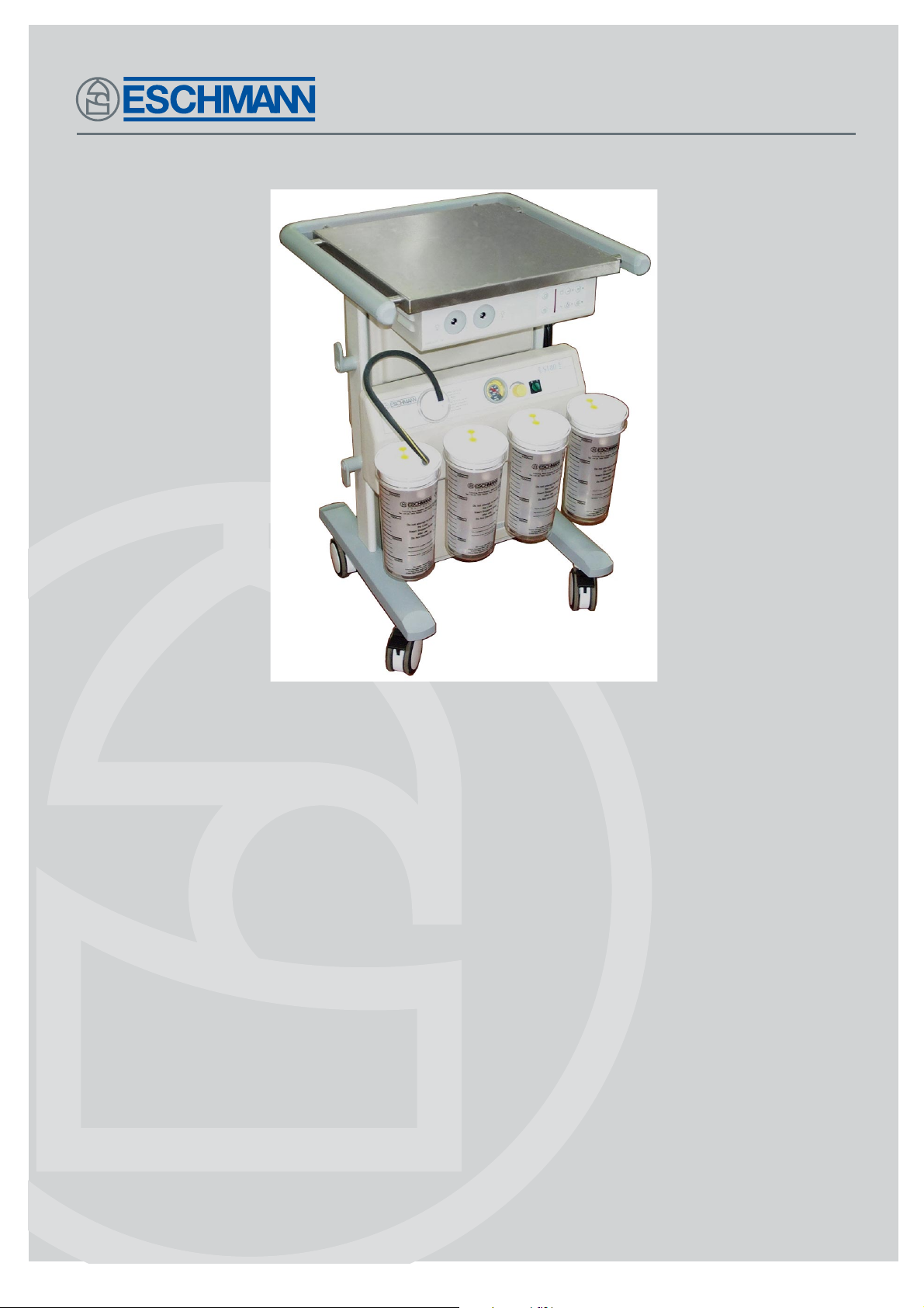
ST80
TROLLEY SYSTEM
Instructions for use
110102
E-IM65c
Page 2
Introduction
Preliminary
information
Read these Instructions before use
Keep these ‘Instructions for use’ in a safe convenient place for future reference during
installation, operation and maintenance procedures.
Safety notes
Installation and
part identification
Instructions
Suction
Instructions
Fibrelight
Technical data
Eschmann After Sales Service Department
The Eschmann After Sales Service Department is staffed and equipped to provide advice and
assistance during normal office hours. To avoid delays when making enquires, please quote the
Model and Serial Number of your Suction Unit and the part number of any part referred to.
(NOTE: For location of the Serial Number Plate see below, the alpha parts of the SN are significant).
Serial plate location for basic unit .....................................................inside vertical support
Serial plate location for unit with Fibrelight (only) ...............................back of Fibrelight unit
Serial plate location for unit with Suction ............................................. back of Suction unit
For further information visit www.eschmann.co.uk
All correspondence relating to the after sales service of Eschmann Equipment to be addressed to :
UK Customers
Eschmann Equipment, Peter Road, Lancing, West Sussex BN15 8TJ, England.
T el: +44 (0) 1903 765040. Fax: +44 (0) 1903 762006.
Overseas Customers
Contact your local distributor. In case of doubt contact Eschmann Equipment.
Trade marks
The ESCHMANN name and logo are registered trade marks of Eschmann Holdings Limit ed.
“Eschmann Equipment” is a trading name of Eschmann Holdings Limi ted.
“ST80” is a trade mark of Eschmann Holdings L imited.
Copyright © 2003
All rights reserved. This booklet is protected by copyright. No part of it may be reproduced, stored in a
retrieval system or transmitted in any form or by any means, electronic, mechanical, photocopying,
recording or otherwise without written permission from Eschmann Holdings Limited.
The information in this publication was correct at the time of going to print. The Company, however,
reserves the right to modify or improve the equipment referred to.
If the CE mark is affixed to the product, it indicates compliance with Council Directive
93/42/EEC of 14 June 1993 concerning medical devices.
E-IM65c August 2003
Instructions for use
Page 3

ST80
TROLLEY SYSTEM
CONTENTS
INTRODUCTION
Introduction. . . . . . . . . . . . . . . . . . . . . . . . . . . . . . . 3
1. PRELIMINARY INFORMATION
General . . . . . . . . . . . . . . . . . . . . . . . . . . . . . . . 4
Optional Extras . . . . . . . . . . . . . . . . . . . . . . . . . 4
2. SAFETY NOTES
Safety notes . . . . . . . . . . . . . . . . . . . . . . . . . . . 5
3. INSTALLATION & PART IDENTIFICATION
Unpacking & Assembly . . . . . . . . . . . . . . . . . . . 7
Electrical Connection. . . . . . . . . . . . . . . . . . . . . 7
Parts Identification . . . . . . . . . . . . . . . . . . . . . . . 7
Important Operating Notes . . . . . . . . . . . . . . . . 7
4. INSTRUCTIONS FOR USE - SUCTION
Liner use . . . . . . . . . . . . . . . . . . . . . . . . . . . . . . 8
Starting the unit . . . . . . . . . . . . . . . . . . . . . . . . . 8
Suction adjustment . . . . . . . . . . . . . . . . . . . . . . 8
Overflow protection . . . . . . . . . . . . . . . . . . . . . . 8
Pump protection . . . . . . . . . . . . . . . . . . . . . . . . 8
Cleaning & Disinfection . . . . . . . . . . . . . . . . . . . 8
Sterilisation . . . . . . . . . . . . . . . . . . . . . . . . . . . . 9
Care - daily checks . . . . . . . . . . . . . . . . . . . . . . 9
Fault diagnosis . . . . . . . . . . . . . . . . . . . . . . . . . 9
INTRODUCTION
NOTE: These Instructions for Use apply to the following
ST80 Trolley Units :-
REF 83-063-05 Electrosurgical trolley
REF 83-063-05-0002 Trolley plus Fibrelight, 230V
REF 83-063-05-0004 Trolley plus Fibrelight, 1 10V
REF 83-063-05-0005 Trolley plus Suction,
230V , 2 Jars
REF 83-063-05-0006 Trolley plus Suction,
100/120V , 2 Jars
REF 83-063-05-0007 Trolley plus Suction,
230V , 4 Jars
REF 83-063-05-0008 Trolley plus Suction,
100/120V , 4 Jars
REF 83-063-05-0010 Trolley + Fibrelight + Suction,
230V , 2 Jars
REF 83-063-05-0012 Trolley + Fibrelight + Suction,
110V, 2 Jars
REF 83-063-05-0014 Trolley + Fibrelight + Suction,
230V , 4 Jars
REF 83-063-05-0016 Trolley + Fibrelight + Suction,
110V, 4 Jars
with Serial Number S8? B 8 B 0000 or later
(‘?’indicates model variant).
5. INSTRUCTIONS FOR USE - FIBRELIGHT
Attaching light guide . . . . . . . . . . . . . . . . . . . . 10
Using the fibrelight source . . . . . . . . . . . . . . . . 10
Lamp changing . . . . . . . . . . . . . . . . . . . . . . . . 10
Cleaning and Disinfection . . . . . . . . . . . . . . . . 10
6. TECHNICAL DATA
Technical data . . . . . . . . . . . . . . . . . . . . . . . . . . . 11
FIGURES
Fig.1 ST80 Part identification . . . . . . . . . . . . . . . . 6
Fig.2 ST80 Changing fibrelight lamp . . . . . . . . . . 10
Fig.3 ST80 Fibrelight part identification . . . . . . . . 10
E-IM65c P3/11
Page 4

1. PRELIMINARY INFORMATION
GENERAL
1.1 The ST80 Trolley system is a modular piece of
theatre equipment available in a range of options:
a) Basic trolley.
b) Trolley with fibrelight system.
c) Trolley with suction system.
d) Trolley with both fibrelight and suction systems.
1.2 The reusable jars supplied with the suction unit are
used with a disposable liner system, as detailed on the
laminated leaflet S-IM08 enclosed with the ST80 Trolley if
a suction unit is fitted.
1.3 The mobile trolley has two breaking castors and a
flat working surface for an electrosurgical unit (optional
extra) or other equipment. It also incorporates removable,
reversible shelving.
1.4 All the information necessary to use the ST80 Trolley
will be found in these Instructions for Use or the Jar and
liner card supplied (if applicable). Because of the modular
nature of this product not all sections of this booklet will
apply. For basic units refer to the relevant parts of the
cleaning and disinfection details section 4.8 - 4.9.
1.5 The following related publications, available from
Eschmann Equipment, also apply to the ST80 Trolley
System.
E-SM52 - Service Manual
S-IM08 - Instructions for Use
(disposable suction liner system)
OPTIONAL EXTRAS
Suction System (see Section 4 for details)
1.6 The vacuum pump is an oil-lubricated electricallydriven pump/motor unit of the rotary vane type, with
replaceable blades. The motor unit is designed to operate
from the mains electrical supply. If required this module
can be added, please contact the Eschmann After Sales
Service Department (see inside front cover).
1.7 The pump/motor unit, its associated pipework and
electrical connections are all contained within a tough,
hygienic plastic case at the base of the ST80. Controls are
mounted on the top of the case and comprise an on/off
power switch, a vacuum control valve and a vacuum gauge.
1.8 A silencer unit in the pump exhaust line ensures
that the pump operates with the minimum of noise, while
the pump inlet is protected by an externally mounted sealed
bacterial or combined hydrophobic/bacterial filter both of
which are disposable.
Fibrelight System (see Section 5 for details)
1.9 The Fibrelight system is a fan-cooled, twin 150 watt
Halogen lamp unit, with both Fibrelight guide adapters and
all controls accessible from the front of the system. Failed
lamps can be easily replaced without the need for any
special tools. If required this module can be added later,
please contact the Eschmann After Sales Service
Department (see inside front cover).
Twin Drip Pole Kit
1.10 The Twin Drip Pole Kit (REF 81-464-03) can be
fitted easily to either, or both sides, of the ST80 Trolley.
The Kit comes complete with all fittings and Instructions
for Use. It provides a conventional style twin drip stand,
taking up less space than an additional free-standing piece
of equipment.
ST80 Trolley System Accessories / Parts List
REF 82-961-68
Filters (pack of 10, bacterial)
REF 82-961-85
Filters (pack of 10, hydrophobic/bacterial)
REF 82-923-61
Jar (with V-mount for disposable liner)
REF 82-923-88
Tapered connector (pack of 10)
REF 82-923-96
Incineration box (pack of 25)
REF 82-929-14
Suction tubing 6.35mm i.d.
REF 82-930-15
Suction tubing (black) 12.7mm i.d.
REF 82-931-12
Suction tubing (clear) 12.7mm i.d.
REF 82-923-57
Disposable liner, standard bore 8.5mm (box of 25)
REF 82-923-69
Disposable liner, wide bore 12.5mm (box of 25)
REF 82-923-65
Disposable liner, Cascade, std. bore 8.5mm (box of 25)
REF 82-929-36
Cascade connecting tube (box of 50)
REF 83-121-41
Fibrelight adaptor, to fit Storz/G.U. guides
REF 83-121-68
Fibrelight adaptor, to fit BS/ACMI guides
REF 81-464-03
ST80 T win drip pole kit
Part No.697603
Fibrelight lamp
P4/11 E-IM65c
Page 5

ST80
TROLLEY SYSTEM
2. SAFETY NOTES
When using the ESCHMANN ST80 TROLLEY
SYSTEM, attention to the following points will
prolong the life of your Trolley System and help
promote safe use.
DO clean all suction equipment and the unit thoroughly
after use.
DO change the disposable filter after each day’s use, or,
IMMEDIATELY if wetted, or, after aspiration of infective
fluids.
DO keep an adequate supply of spare disposable filters
handy.
DO unplug and/or isolate power lead before cleaning
suction unit and when not in use.
DO treat receiver jars carefully, avoiding mechanical or
thermal shock.
DO examine condition of jars and suction tubing regularly,
replacing if worn or damaged.
DO seal disposable liner after use and don’t reopen.
DO use a new liner and a new suction tube for each
patient - don’t risk cross infection.
DO autoclave receiver jar daily.
DO keep ‘sharps’ away from liners.
DO read these ‘Instructions for Use’ carefully and keep in
an accessible place.
WARNING
Operators of this unit should be aware of the
potential risks of ‘Cross Contamination’ and
‘Biological Contamination’ whilst using this
equipment. The correct procedures for the handling
of potentially contaminated components (e.g. Jar,
Tubing, Filters) and liquids should be followed
rigidly during Use, Cleaning and Maintenance.
Always change filters regularly and if they become
wetted or contaminated. All users should be familiar
with the procedures for dealing with, and disposing
of, potentially contaminated components and
liquids. Suction equipment should only be used by
persons who have received adequate instructions
in its use.
The contents of the liner and accessories should
be disposed of safely and carefully, taking into
account any National, Local or Hospital procedures,
covering the disposal of potentially contaminated
liquid, or solid, waste.
The maintenance procedures described in these
‘Instructions for Use’ should be made the
responsibility of the engineer in charge of services
in the hospital. If maintenance is neglected, suction
performance could be found inadequate in an
emergency situation. It is also recommended that if
placed on stand-by for emergency duty the unit is
tested by switching on, at regular intervals.
DON’T start unit without removing transit bolt and filling
pump with oil.
DON’T use substitute disposable filters (see available
spares list on page 4).
DON’T continue to use unit, without attention, if vacuum
reading or suction rate is too low.
DON’T obstruct or cover ventilation holes in unit cabinet.
DON’T use the electrical power lead or suction tubing as
a tow rope, use the unit’s handle.
DON’T leave part filled liners in the system overnight -
always incinerate.
DON’T overfill suction liners - change when three quarters
full.
DON’T use phenols or solvent based disinfectants to
clean receiver jar, use Savlon, Hibitane or similar
(also see leaflet S-IM08 supplied with the unit).
DON’T touch inside surface of fibrelight lamp reflector or
the quartz bulb.
E-IM65c P5/11
Page 6

1. Trolley top
2. Fibrelight controls and indicators.
3. Fibrelight case
4. Fibrelight lamp plate
5. Vacuum gauge
6. Vacuum power switch
7. Vacuum control valve
8. Receiver jar mounting bracket
9. Pump case
10. Receiver jar with liner
11. Castor
12. Foot assembly
13. Cable cleat
14. Front moulding
15. Disposable filter (either type)
16. Shelving (reversible if basic unit only)
17. Side frame
18. Handrail
19. Connecting tubing
20. Suction electrical rating plate
21. Suction system fuses
22. Pump exhaust outlet
23. Mains supply cable
24. Fibrelight system fuses
25. Fibrelight electrical supply socket
26. Air intake for fibrelight fan
27. Fibrelight electrical rating plate
Fig. 1 ST80 Trolley - parts identification
P6/11 E-IM65c
Page 7

ST80
TROLLEY SYSTEM
3. INSTALLATION AND
PART IDENTIFICATION
Unpacking and assembly
3.1 Proceed carefully as follows:
i) Remove muff (UK market) or open carton
(Overseas market).
ii) Remove loosely packed items and documents
and carefully remove the ST80 unit from the
carton.
iii) If Trolley has a suction system fitted, remove
motor transit screw (painted red) from base of
pump case and discard screw.
Note: The vacuum pump is supplied charged with oil and
ready for use. Recharging instructions are included in the
Service Manual.
3.2 The suction collection system (if fitted) is provided
with two or four 1600ml receiver jars (working capacity).
Remove any loose items from within the jars.
3.3 If required, clean and sterilize jars before use as
described in leaflet S-IM08 supplied with the unit, where
preferred methods are detailed.
3.4 Fit disposable liners in the jars and place the jars in
the mounting brackets (item 8, Fig. 1) at the front of unit.
(Also see 1.2).
3.5 Then insert either the hydrophobic/bacterial filter,
or the bacterial type filter (item 15, Fig. 1) into the rubber
mount on the front moulding as shown in Fig. 1. (Note:
Filters will only fit one way round).
3.6 Connect the connector on the connecting tubing
(item 19, Fig. 1) to the filter. Ensure that the tapered
connector on the free end of the tubing is pushed firmly
into the socket in the disposable liner.
Electrical connection
3.7 Connect a three-pin fused plug, if not already fitted
to the mains supply cable. If the plug is removed a new
plug should be fitted (with a 5A fuse) as follows:
Brown . . . . . . . . . . . . . . . . . . . . . . . Live
Blue . . . . . . . . . . . . . . . . . . . . . . . Neutral
Green/Yellow . . . . . . . . . . . . . . . . . Earth
Dispose of the removed plug safely having first removed
its fuse.
3.8 The mains supply must agree with the information
on the electrical rating plate at the rear of the unit. In the
UK a 5A fuse must always be fitted in the plug if the fuse is
replaced.
Parts identification
3.10 Refer to Fig. 1 to gain knowledge of the names for
various parts of the ST80 Trolley.
3.11 The suction collection system utilises a disposable
liner system, leaflet (S-IM08) supplied with the unit explains
how to use them.
3.12 The front two castors of the trolley incorporate a
foot operated brake. To apply the brake press the bottom
of the lever until it locks in the down position with a click. T o
release the break apply pressure to the top of the lever
until it releases.
Brake Lever
Important operating notes
3.13 The following notes should be followed when
operating the ST80 suction system :
i. This suction unit is not intended for field and
transport use.
ii. The suction pump must be removed and
serviced if liquid or solid matter has been drawn
into it.
iii. It is recommended that this suction unit is used
only on a horizontal floor or surface.
iv. This suction system incorporates an overfill
device (float valve) which will operate and stop
suction in an ‘overfill’ situation. See leaflet
(S-IM08) supplied with the unit for more details
and information on disposal.
v. The recommended suction tubing is sterile
tubing for surgical suction of 6.35mm (1/4 inch)
inner diameter (see parts list on page 4). The
method of connection to the liner is described
in the leaflet (S-IM08).
WARNING
The ST80 high vacuum suction unit should not be
used for continuous drainage of body cavities.
Nevertheless it should be noted that the pump is
rated for continuous operation. A new disposable
liner and a new suction tube, must be used for each
patient.
3.9 Suction and fibrelight functions can be used
independently by selecting the appropriate switches.
E-IM65c P7/11
Page 8

4. INSTRUCTIONS FOR USE SUCTION SYSTEM
Liner use
4.1 The ST80 suction system uses a jar and disposable
liner system. The leaflet (S-IM08) supplied with the unit
explains how to use them.
NOTE: Graduations are approximate; suitable volume
measuring equipment should be used if accurate
assessment is required (e.g. the CMV see S-IM08).
Starting the unit
4.2 Connect unit to mains electrical supply and if supply
socket is controlled by a switch, ensure it is switched ‘ON’.
4.3 Ensure installation stages 3.3 to 3.8 have been
followed then start the vacuum pump by turning the mains
switch (item 6, Fig. 1) to ‘l’. Adjust the Vacuum to the
required level as detailed in section 4.4.
Note: Before using the suction unit for the first time, the
suction performance can be checked quickly by switching
on the unit and placing a finger over the end of the
connecting tube (item 19, Fig. 1). The vacuum gauge
reading should move quickly to approximately 620 mm Hg
(atmosphere at 760 mm Hg) with vacuum control valve
turned to maximum setting.
Suction adjustment
Inlet connection
Clear top
Outlet
connection
environmental protection from contaminated suction pump
exhaust. Should the hydrophobic filter become wetted it
will prevent fluid passing into the pump but still allow suction
to continue. Only when the filter upper chamber is full of
fluid, will suction cease. The second filter, the bacterial type
shown below, provides improved protection against
Outlet
connection
bacteria and other airborne pathogens from the pump
exhaust. In the event of becoming wetted this filter will not
prevent body fluids contaminating the pump. Also see
WARNING on page 5.
Blue base
Inlet connection
Clear top
and Base
4.4 T o set the required vacuum on this suction unit switch
the mains switch ‘ON’ (mains switch to ‘1’), place a finger
over the nozzle (patient inlet) of the liner to which the
"patient" tubing connects, then turn the vacuum control
valve (item 7, Fig. 1) clockwise or anticlockwise to increase
or decrease the suction until the desired vacuum is
indicated on the vacuum gauge.
4.5 When applying suction to the patient it may be
desirable to increase or decrease the suction rate. This is
achieved by turning the vacuum control valve clockwise to
increase or counter-clockwise to decrease suction.
Overflow protection
4.6 Aspiration should be stopped when level of fluid
reaches approximately the 3/4 full mark, but in the event
of accidental overfilling the float valve will close shutting
off vacuum to the liner .
Pump protection
4.7 The sealed disposable filter, of either type, must be
changed after each day’s use or immediately if wetted or
after aspiration of infective fluids. The hydrophobic/bacterial
filter shown provides total environmental protection pump
protection from body fluids together with improved
WARNING
Do not use substitutes for the specified sealed
disposable filters see parts list on page 4.
Cleaning & disinfection
WARNING
Disconnect equipment from the mains electrical
supply prior to cleaning and disinfection.
4.8 The following routine should be carried out
immediately after each period of use:
i. The disposable filters must be changed after
each day's use, or IMMEDIATELY if wetted, or
after aspiration of infective fluids.
ii. All components likely to be in contact with
aspirated body fluids should be thoroughly
cleaned and sterilized after use, or whenever it
is suspected that infective fluids have been in
contact with the unit.
iii. The outside of the unit should be washed with
hot (55°C) neutral (pH7) detergent solution
(diluted in accordance with the manufacturers
instructions) rinsed with clean water, and wiped
dry.
P8/11 E-IM65c
Page 9

ST80
TROLLEY SYSTEM
v. Phenol based disinfectants and solvent based
liquids should not be used for cleaning receiver
jars, use aqueous based liquids at all times.
4.9 The following disinfection procedure is used by
Eschmann Equipment, and its use is recommended if no
other approved procedures are available.
i Remove all jars and filters etc. and sterilize or
dispose of separately as required.
ii Wash down all surfaces and crevices with hot
(55°C) neutral (pH7) detergent solution (diluted
in accordance with the manufacturers
instructions) to remove all visible contamination.
Use a small brush to clean areas of limited
access.
iii W ash down with hot (55°C) water.
iv Dry all surfaces with absorbent paper.
v Wash down all surfaces and crevices with a 70%
solution of industrial methylated spirit and water.
vi Allow to dry by evaporation.
vii Dispose of all cleaning material and solutions in
accordance with authorized disposal
procedures.
WARNING
Do not allow Hypochlorite solutions to come
into contact with any metal components.
Sterilization of jars
4.10 See leaflet S-IM08 supplied with the unit.
Care - Daily checks
4.11 T o ensure the ST80 Suction Unit operates ef ficiently
in an emergency, the following checks should be carried
out on a daily basis:
i. Check jar for cracks or chips, renew if damaged.
ii. Check suction performance as detailed in the
‘note’ after section 4.3.
Note: Disposable filters, suction tubing, jars and liners
are relatively inexpensive items, and a stock of spares
should always be readily available (see parts list on page 4).
F AUL T DIAGNOSIS
4.12 The following table lists possible causes of faults that can be rectified by the user. Rectification of other faults
can only be carried out by trained personnel in conjunction with the relevant Service Manual.
Fault Possible Cause Remedy
1. Total loss of (a) Disconnection in suction line (a) Reconnect
suction (b) Overflow protection operated (b) Switch to new liner
(c) Disposable filter completely (c) Replace filter immediately
blocked
2. Partial loss of (a) Split or damaged liner (a) Replace liner
suction (b) Leakage in suction line (b) Check/remake suction
connections/renew tubing
(c) Disposable filter wetted (c) Replace filter immediately
or fouled
3. Vacuum gauge (a) Loss of vacuum (a) See (1) and (2) above
no indication
4. No power (a ) Fuse in ‘mains’ plug faulty (a ) Check/replace fuse (5Amp)
(b ) Mains supply failure (b ) Check ‘mains’ supply
5. On switching pump off (a) Leakage in suction tubing or (a) Tighten or renew faulty items
with inlet blocked, connections
immediate vacuum loss
Note: A thermal overload switch, which is self-resetting, is incorporated to protect the motor in the event of
pump seizure or excessive running temperatures. Should the overload switch operate to stop the motor it is
essential to disconnect the electrical supply to the unit before attempting any form of maintenance. In the case of
faults which cannot be resolved, please contact the Eschmann After Sales Service Department (see inside front
cover for contact information).
E-IM65c P9/11
Page 10

Attaching Light Guide (Fig. 3)
5.1 Screw appropriate adapter(s) into lamp plate (item
12 Fig.3) sockets and connect flexible light guide to adapter.
(See parts list page 4 for adapters available from Eschmann
Equipment)
Using Fibrelight Source (Fig. 3)
5.2 Connect fibrelight assembly to mains electrical
supply and if supply socket is controlled by a switch, ensure
that it is switched ‘on’. The amber stand-by indicator (item
7) will illuminate.
5.3 Press lamp ‘on’ touch button (item 6), lamp ‘on’
indicator (item 5) will illuminate green.
5.4 Press lamp selector button (item 1) or (item 3),
corresponding stand-by lamp indicator (item 2) or (item 4)
will illuminate amber.
5.5 Press button (item 11) to increase or button (item
10) to decrease brightness.
5.6 In the event of lamp failure, press button (item 1) or
(item 3) and reposition light guide to other adapter.
v Hold new lamp (see parts list page 4) by
connector pins and/or rim of reflector and with
the key (item 3) as shown. Then locate lamp in
lamp holder (item 4), ensuring connector pins
are aligned with sockets, and push lamp firmly
into position.
vi Raise fibrelight chassis and secure in closed
position.
vii Connect equipment to mains electrical supply.
viii T est both lamps as detailed in 5.3 to 5.5.
Cleaning & disinfection
5.8 See the relevant parts of 4.8-4.9
Lamp changing (Fig. 2)
5.7 T o change a lamp proceed as follows:
i Disconnect equipment from the mains electrical
supply.
ii If necessary, allow lamp(s) to cool.
iii Release flap catch (item 1) and supporting
fibrelight chassis (item 2), hinge chassis
carefully downwards.
iv Raise ejector lever (item 5) to remove the failed
lamp.
CAUTION
Do not touch inside surface of new lamp reflector
or the quartz bulb as this will impair efficiency and
shorten lamp life. Hold new lamp reflector as shown
in Fig. 2.
1. Flap catch
2. Chassis
3. Key
4. Lamp holders
5. Lamp ejector lever
6. Lamp
Fig. 2 ST80 Changing fibrelight lamp
1. Lamp selector touch button
2. Stand-by lamp indicator (amber)
3. Lamp selector touch button
4. Stand-by lamp indicator (amber)
5. Lamp ‘on’ indicator (green)
6. Lamp ‘on’ touch button
7. Stand-by indicator (amber)
8. Lamp ‘off’ touch button
9. Brightness display (red)
10. Decrease brightness touch button
11. Increase brightness touch button
12. Fibrelight lamp plate
Fig. 3 ST80 Fibrelight - Parts identification
P10/11 E-IM65c
Page 11

TROLLEY SYSTEM
6. TECHNICAL DAT A
General
Equipment Type: Mobile trolley system, of modular construction.
Overall dimensions (approx.): Height, 880 mm Width, 590 mm Depth, 615 mm
Weight (approx): T rolley, 26kg Trolley + Suction, 45kg T rolley + Suction + F’light, 54kg
Suction system
Either: Connection to Hospital piped vacuum, or,
Internal Pump:
Type: High vacuum, high flow, oil lubricated rotary vane type, mains operated.
Oil charge: 25ml (approx.) Oil type: Eschmann ‘Universal’, High Vacuum Oil
Performance: Maximum airflow rate, 35 litre/min Nominal vacuum, 620 mm Hg (80kPa)
Electric motor: T otally enclosed, fan cooled, Power consumption 60W
Duty cycle, Continuous Mains input: 230V a.c. 50/60 Hz, or 1 10V a.c. 50/60 Hz
Fuses: (2 off) for 230V supply, T2A anti-surge 20mm to IEC127
(2 off) for 100/120V supply, T5A anti-surge 20mm to IEC127
Filters: Sealed disposable combined hydrophobic/bacterial type designed to provide
100% pump protection against aqueous fluids, or, Sealed disposable bacterial type
ST80
Fibrelight system
Type: High intensity fan cooled light source for fibrelight endoscopic instruments.
Mains input: 230V a.c. 50/60Hz
Output: Continuously variable Duty: Continuous Power consumption: 150W
Fuses: (2 off) for 230V supply, T1.6A anti-surge 20mm to IEC127
(2 off) for 100/120V supply, T3.15A anti-surge 20mm to IEC127
Lamps: Prefocused 150 watt Quartz Halogen type, (2 off - selectable)
Safety
Standards : EN 60601-1:1990+A1:1993+A2:1995, ISO 10079-1:1991,
BS 5724:Part 1:1979, IEC 601-1:1977
Classification : Class 1. Type BF Drip proof
Electromagnetic compatibility : IEC 601-1-2:1993
Class
Class 1 denotes that the equipment must be earthed via the protective conductor
in the 3-core mains cable connected to a 3-pin plug.
Explanation of symbols
The symbol (drip proof) indicates that the equipment will withstand
a moderate quantity of water spilled from above the unit.
The symbol denotes that the equipment is in the category type BF, i.e. that it is manufactured to a safety standard
commensurate with international regulations for medical electrical equipment incorporating floating patient applied
parts.
The symbol indicates that the equipment isfor use on alternating current only.
The symbol indicates that vacuum is increased by clockwise rotation of this control.
For SINGLE USE ONL Y
E-IM65c P11/11
Page 12

Page 13

Page 14

Eschmann Equipment, Peter Road, Lancing, West Sussex, BN15 8TJ, England.
T el: +44 (0) 1903 753322. Fax: +44 (0) 1903 766793. www.eschmann.co.uk
 Loading...