

Page 1

SERVICE MANUAL
Color Inkjet Printer
Epson WorkForce 635/Epson Stylus Office TX620FWD/
Epson Stylus Office BX625FWD/Epson ME OFFICE 960FWD
Epson WorkForce 620/625/Epson Stylus TX560WD/SX525WD/
Epson Stylus Office BX525WD/Epson ME OFFICE 900WD
Epson WorkForce 60/T42WD/
Epson Stylus Office B42WD/Epson ME OFFICE 82WD
Epson ME OFFICE 85ND
CONFIDENTIAL
SEMF09-016
Page 2

Safety Precautions
All safety procedures described here shall be strictly adhered to by all parties servicing and maintaining this
product.
DANGER
Strictly observe the following cautions. Failure to comply could result in serious bodily injury or loss of life.
1. Always disconnect the product from the power source and peripheral devices when servicing the product or
performing maintenance.
2. When performing works described in this manual, do not connect to a power source until instructed to do so.
Connecting to a power source causes high voltage in the power supply unit and some electronic components
even if the product power switch is off. If you need to perform the work with the power cable connected to a
power source, use extreme caution to avoid electrical shock.
WARNING
Strictly observe the following cautions. Failure to comply may lead to personal injury or loss of life.
1. Always wear protective goggles for disassembly and reassembly to protect your eyes from ink in working. If
any ink gets in your eyes, wash your eyes with clean water and consult a doctor immediately.
2. When using compressed air products; such as air duster, fo r cleaning during repair and maintenance, the use
of such products containing flammable gas is prohibited.
PRECAUTIONS
Strictly observe the following cautions. Failure to comply may lead to personal injury or damage of the product.
1. Repairs on Epson product should be performed only by an Epson certified repair technician.
2. No work should be performed on this product by persons unfamiliar with basic safety knowledge required for
electrician.
3. The power rating of this product is indicated on the serial number/rating plate. Never connect this product to
the power source whose voltages is different from the rated voltage.
4. Replace malfunctioning components only with those components provided or approved by Epson;
introduction of second-source ICs or other non-approved components may damage the product and void any
applicable Epson warranty.
5. In order to protect sensitive microprocessors and circuitry, use static discharge equipment, such as anti-static
wrist straps, when accessing internal components.
6. Do not tilt this product immediately after initial ink charge, especially after performing the ink charge several
times. Doing so may cause ink to leak from the product because it may take some time for the waste ink pads
to completely absorb ink wasted due to the ink charge.
7. Never touch the ink or wasted ink with bare hands. If ink comes into contact with your skin, wash it off with
soap and water immediately. If you have a skin irritation, consult a doctor immediately.
Confidential
Page 3

8. When disassembling or assembling this product, make sure to wear gloves to avoid injuries from metal parts
with sharp edges.
9. Use only recommended tools for disassembling, assembling or adjusting the printer.
10. Observe the specified torque when tightening screws.
11. Be extremely careful not to scratch or contaminate the following parts.
Nozzle plate of the printhead
CR Scale
PF Scale
Coated surface of the PF Roller
Gears
Rollers
LCD
Scanner Sensor
Exterior parts
12. Never use oil or grease other than those specified in this manual. Use of different types of oil or grease may
damage the component or give bad influence on the printer function.
13. Apply the specified amount of grease described in this manual.
14. Make the specified adjustments when you disassemble the printer.
15. When cleaning this product, follow the procedure described in this manual.
16. When transporting this product after filling the ink in the printhead, pack the printer without removing the
ink cartridges in order to prevent the printhead from drying out.
17. Make sure to install antivirus software in the computers used for the service support activities.
18. Keep the virus pattern file of antivirus software up-to-date.
Confidential
Page 4

About This Manual
This manual, consists of the following chapters, is intended for repair service personnel and includes information
necessary for properly performing maintenance and servicing the product.
CHAPTER 1. DISASSEMBLY / REASSEMBLY
Describes the disassembly/reassembly procedures for main parts/units of the product, and provides the
standard operation time for servicing the product.
CHAPTER 2. ADJUSTMENT
Describes the required adjustments for servicing the product.
CHAPTER 3. MAINTENANCE
Describes maintenance items and procedures for servicing the product.
CHAPTER 4. APPENDIX
Provides the following additional information for reference:
Power-On Sequence
Connector Diagram
Troubleshooting
Symbols Used in this Manual
Various symbols are used throughout this manual either to provide additional information on a specific topic or
to warn of possible danger present during a procedure or an action. Pay attention to all symbols when they are
used, and always read explanation thoroughly and follow the instructions.
Indicates an operating or maintenance procedure, practice or condition that, if not strictly observed,
could result in serious injury or loss of life.
Indicates an operating or maintenance procedure, practice, or condition that, if not strictly observed,
could result in bodily injury, damage or malfunction of equipment.
May indicate an operating or maintenance procedure, practice or condition that is necessary to
accomplish a task efficiently. It may also provide additional information that is related to a specific
subject, or comment on the results achieved through a previous action.
For Chapter 1 “Disassembly/Reassembly”, symbols other than indicated above are used to show additional
information for disassembly/reassembly. For the details on those symbols, see "1.2 Disassembly/Reassembly
Procedures (p12) ".
Confidential
Page 5

Revision Status
Revision Date of Issue Description
A April 28, 2010 First Release
B August 6, 2010 Revised Contents
Chapter 1
"1.1.2 Jigs (p11)" has been added.
The Stopper Assy has been added and made change in "Table 1-1 Standard Operation
Time (WorkForce 635 series) (TBD) (p13)" of "1.2.1 Standard Operation Time for
servicing the product (TBD) (p13)".
Made change in "Table 1-2 Standard Operation Time (WorkForce 620 series) (TBD)
(p14)" of "1.2.1 Standard Operation Time for servicing the product (TBD) (p13)".
Made change in "1.2.2 Disassembly/Reassembly Flowchart (p17)".
Made change in "1.3 Detailed Disassembly/Reassembly Procedure for each Part/Unit
(p22)".
• Made change in " Document Pad (WorkForce 635/620 series) (p22)".
• Made change in " Left Housing/Right Housing (WorkForce 635/620 series) (p22)".
• Made change in " Panel Unit (WorkForce 635/620 series) (p22)".
• Made change in " Lower Panel Housing (WorkForce 635/620 series) (p22)".
• Made change in " Panel Board (WorkForce 635/620 series) (p23)".
• Made change in " Ink System Assy (p23)".
• Made change in " FAX Shield Plate/FAX Connector Cover (WorkForce 635 series)
(p23)".
• Made change in " Star Wheel Assy (p23)".
• Made change in " Main Board Unit (WorkForce 635/620 series) (p24)".
• Made change in " Front Frame (p24)".
• Made change in " Main Frame (w/ CR Assy) (p24)".
• Made change in " Printhead (p24)".
• Made change in " ADF Unit (WorkForce 635 series) (1) (p25)".
• Made change in " ADF Unit (WorkForce 635 series) (2) (p25)".
• " Paper Guide Front Assy (installation using the tools) (p26)" has been added.
• " Paper Guide Front Assy (Stopper Holder Idle Roller) (p26)" has been added.
• " LCD (WorkForce 635/620 series) (p26)" has been added.
• Made change in " Front Paper Guide Waste Ink Pad (p26)".
• " Stopper Assy (WorkForce 620 series) (p26)" has been added.
Made change in "1.4 Routing FFCs/cables (p28)".
• Made change in " Inside the USB Cover (WorkForce 635 series) (p28)".
• Made change in " Panel Unit (WorkForce 635 series) (p28)".
• Made change in " Scanner FFC/Scanner Motor Cable (WorkForce 635/620 series)
(p28)".
• Made change in " P/S Board Assy (WorkForce 635/620 series) (p28)".
• Made change in " FAX Assy (WorkForce 635 series) (p28)".
• Made change in " Head FFC (p29)".
• Made change in " Main Board (WorkForce 635 series) (p29)".
• Made change in " PF Motor (p29)".
• Made change in " PE Sensor (p29)".
• Made change in " Inside the USB Cover (WorkForce 620 series) (p30)".
• Made change in " Main Board (WorkForce 620 series) (p30)".
• Made change in " Panel Unit (WorkForce 620 series) (p29)".
Chapter 2
Made change in "2.1 Required Adjustments (p32)".
"2.2.1 PF Timing Belt Tension Measurement/PF Belt Step Check (p38)" has been
added.
"2.2.2 Checking the Platen Gap (p41)" has been added.
Confidential
Page 6

Revision Date of Issue Description
B August 6, 2010
Chapter 3
Made change in "3.1.2 Lubrication (p44)".
Made change in "3.2 Lubrication Points and Instructions (p45)".
• Made change in "Fig. 3-1 Lubrication of the Driven Pulley Holder (p45)".
• Made change in "Fig. 3-2 Lubrication of the Paper Guide Front Assy (PF Roller) (p45)".
• Made change in "Fig. 3-3 Lubrication of the Paper Guide Front Assy (EJ Roller) (p45)".
• Made change in "Fig. 3-5 Lubrication of the PF Holder (p45)".
• Made change in "Fig. 3-6 Lubrication of the Main Frame (1) (p46)".
• Made change in "Fig. 3-8 Lubrication of the EJ Pulley (p46)".
• Made change in "Fig. 3-9 Lubrication of the Ink System Assy (1) (p46)".
• Made change in "Fig. 3-10 Lubrication of the Ink System Assy (2) (p46)".
• Made change in "Fig. 3-11 Lubrication of the CR Assy (p46)".
• Made change in
•
"Fig. 3-15 Lubrication of the Stopper Assy (WorkForce 620 series) (p48)"
"Fig. 3-12 Lubrication of the Scanner Unit (WorkForce 635/620 series) (p47)"
Chapter 4
Made change in "4.1 Power-On Sequence (p50)".
"4.3 Troubleshooting (p54)" has been added.
.
has been added.
Confidential
Page 7

Revision Date of Issue Description
C October 12, 2010 Revised Contents
All chapters
Information of Epson WorkForce 60/T42WD/Epson Stylus Office B42WD/
Epson ME OFFICE 82WD/Epson ME OFFICE 85ND has been added.
Chapter 1
Production name has been added in "1.1 Overview (p11)".
Made change in "1.1.2 Jigs (p11)".
Made change in "1.2 Disassembly/Reassembly Procedures (p12)".
Made change in
• "1-3 Standard Operation Time (WorkForce 60 series) (TBD) (p15)" has been added.
"1.2.1 Standard Operation Time for servicing the product (TBD) (p13)"
Made change in "1.2.2 Disassembly/Reassembly Flowchart (p17)".
• Made change in
• "1.2.2.2 Housing Part (WorkForce 60 series) (p19)" has been added.
• Made change in "1.2.2.3 Printer Mechanism Part (p20)".
Made change in
• Production name has been added in
• Production name has been added in
• Production name has been added in
• Production name has been added in " Left Housing/Right Housing (WorkForce 635/620
series) (p22)".
• Production name has been added in " Panel Unit (WorkForce 635/620 series) (p22)".
• Production name has been added in " Upper Housing (w/ Panel Unit) (WorkForce 635/
620 series) (p22)".
•
Production name has been added in
• Production name has been added in " Panel Board (WorkForce 635/620 series) (p23)".
• Made change in " CR Scale/Extension Spring (p23)".
• Production name has been added in " Shield Plate (w/ Wireless LAN Module)
(WorkForce 635/620 series) (p23)".
• Production name has been added in " Wireless LAN Module (p23)".
• Production name has been added in
• Production name has been added in " CIS Unit (WorkForce 635/620 series) (p24)".
• Made change in " Paper Guide Front Assy (installation using the tools) (p26)".
• Made change in " Paper Guide Front Assy (Stopper Holder Idle Roller) (p26)".
• Production name has been added in " LCD (WorkForce 635/620 series) (p26)".
• " Front Cover (WorkForce 60 series) (p27)" has been added.
• " USB Cover (WorkForce 60 series) (p27)" has been added.
• " Upper Housing (WorkForce 60 series) (p27)" has been added.
• " Stacker Assy (WorkForce 60 series) (p27)" has been added.
• " Main Board Unit (WorkForce 60 series) (p27)" has been added.
"1.2.2.1 Housing Part (WorkForce 635 series/WorkForce 620 series) (p17)"
"1.3 Detailed Disassembly/Reassembly Procedure for each Part/Unit (p22)"
" USB Cover (WorkForce 635/620 series) (p22)"
" Decoration Plate (WorkForce 635/620 series) (p22)"
" Document Pad (WorkForce 635/620 series) (p22)"
" Lower Panel Housing (WorkForce 635/620 series) (p22)"
" Main Board Unit (WorkForce 635/620 series) (p24)"
.
.
.
.
.
.
.
.
Confidential
Page 8

Revision Date of Issue Description
C October 12, 2010
Made change in "1.4 Routing FFCs/cables (p28)".
• Production name has been added in
• Production name has been added in
series) (p28)"
• Production name has been added in
• Production name has been added in
•
" Main Board (WorkForce 60 series) (p30)"
.
" Cover Open Sensor (WorkForce 635/620 series) (p28)"
" Scanner FFC/Scanner Motor Cable (WorkForce 635/620
" P/S Board Assy (WorkForce 635/620 series) (p28)"
" PF Encoder Sensor (WorkForce 635/620 series) (p29)"
has been added.
Chapter 2
Made change in "2.2.1 PF Timing Belt Tension Measurement/PF Belt Step Check
(p38)".
Chapter 3
Made change in "3.2 Lubrication Points and Instructions (p45)".
• Production name has been added in "3-12 Lubrication of the Scanner Unit (WorkForce
635/620 series) (p47)".
• Production name has been added in "3-13 Lubrication of the Duplex Unit (p47)".
• Production name has been added in "3-15 Lubrication of the Stopper Assy (WorkForce
620 series) (p48)".
Chapter 4
Made change in "4.2 Connector Diagram (p53)".
Made change in "4.3.1 Troubleshooting Workflow (p54)".
Made change in "4.3.2 Fatal Error Code (p56)".
.
.
.
Confidential
Page 9

Epson WorkForce 635/620/60 series Revision C
Contents
Chapter 1 Disassembly/Reassembly
1.1 Overview. ................................................................................................................................................................. 11
1.1.1 Tools. ............................................................................................................................................................... 11
1.1.2 Jigs. .................................................................................................................................................................. 11
1.2 Disassembly/Reassembly Procedures ...................................................................................................................... 12
1.2.1 Standard Operation Time for servicing the product (TBD) ............................................................................ 13
1.2.2 Disassembly/Reassembly Flowchart............................................................................................................... 17
1.2.2.1 Housing Part (WorkForce 635 series/WorkForce 620 series)................................................................ 17
1.2.2.2 Housing Part (WorkForce 60 series) ...................................................................................................... 19
1.2.2.3 Printer Mechanism Part .......................................................................................................................... 20
1.3 Detailed Disassembly/Reassembly Procedure for each Part/Unit............................................................................ 22
1.4 Routing FFCs/cables . ............................................................................................................................................... 28
Chapter 2 Adjustment
2.1 Required Adjustments.............................................................................................................................................. 32
2.2 Details of Adjustments............................................................................................................................................. 38
2.2.1 PF Timing Belt Tension Measurement/PF Belt Step Check ........................................................................... 38
2.2.2 Checking the Platen Gap ................................................................................................................................. 41
2.2.3 MAC Address Setting...................................................................................................................................... 42
Chapter 3 Maintenance
3.1 Overview. ................................................................................................................................................................. 44
3.1.1 Cleaning........................................................................................................................................................... 44
3.1.2 Lubrication....................................................................................................................................................... 44
3.2 Lubrication Points and Instructions.......................................................................................................................... 45
Chapter 4 Appendix
4.1 Power-On Sequence. ................................................................................................................................................ 50
4.2 Connector Diagram . ................................................................................................................................................. 53
4.3 Troubleshooting. ....................................................................................................................................................... 54
4.3.1 Troubleshooting Workflow ............................................................................................................................. 54
4.3.2 Fatal Error Code . ............................................................................................................................................. 56
9
Confidential
Page 10

CHAPTER 1
DISASSEMBLY/REASSEMBLY
Confidential
Page 11

Epson WorkForce 635/620/60 series Revision C
1.1 Overview
This chapter describes procedures for disassembling the main parts/units of WorkForce 635 series, WorkForce
620 series and WorkForce 60 series. Unless otherwise specified, disassembled parts/units can be reassembled by
reversing the disassembly procedure. See the cautions or tips for disassembly/reassembly described in "1.3
Detailed Disassembly/Reassembly Procedure for each Part/Unit (p22)".
Read the " Safety Precautions (p3)" before disassembling and reassembling.
When you have to remove units or parts that are not described in this chapter, see the exploded diagrams of SPI
(Service Parts Information).
In this chapter, the product names are called as follows:
WorkForce 635 series:WorkForce 635/Epson Stylus Office TX620FWD/
Epson Stylus Office BX625FWD/ME OFFICE 960FWD
WorkForce 620 series:WorkForce 620/625/Epson Stylus TX560WD/
Epson Stylus SX525WD/Epson Stylus BX525WD/
ME OFFICE 900WD
WorkForce 60 series: WorkForce 60/T42WD/
Epson Stylus Office B42WD/ME OFFICE 82WD/
ME OFFICE 85ND
1.1.1 Tools
Use only specified tools to avoid damaging the printer.
Name Availability EPSON Part Code
(+) Phillips screwdriver #1 O 1080530
(+) Phillips screwdriver #2 O --Flathead screwdriver O --Flathead Precision screwdriver #1 O --Tweezers O --Longnose pliers O --Acetate tape --- 1003963
Nippers O ---
Note 1: Some of the tools listed above are commercially available.
2: EPSON provides the tools listed with EPSON part code.
1.1.2 Jigs
Name Q’ty EPSON Part Code
Paper guide front supporting tool (A)* 1 WorkForce 635 series: 1543170
WorkForce 620 series: 1543171
WorkForce 60 series: 1543170
Paper guide front supporting tool (B)* 1 WorkForce 635 series: 1543539
WorkForce 620 series: 1543544
WorkForce 60 series: 1543539
Paper guide front supporting tool (C)* 3 WorkForce 635 series: 1543541
WorkForce 620 series: 1543547
WorkForce 60 series: 1543541
Printhead supporting tool 2 1543169
Note *: The required tools differ between WorkForce 635 series, WorkForce 620 series and WorkForce 60 series. Be careful not to mix
up the tools.
Disassembly/Reassembly Overview 11
Confidential
Page 12
Epson WorkForce 635/620/60 series Revision C
USB Cover
1
2
(p 22) (p 28)
Ink System Assy
1
1
(p 23) (p 46)
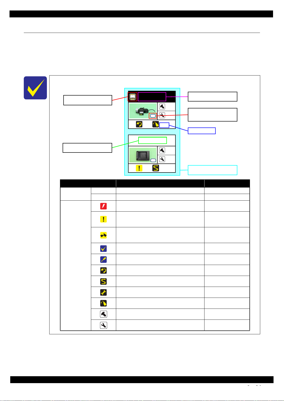
Ref.
Item Description Reference
Parts/unit name
White-letter
Part/unit supplied as an ASP ---
Black-letter
Part/unit not supplied as an ASP ---
Icon
Indicates a practice or condition that could result in
injury or loss of life if not strictly observed.
Indicates the reference
page in blue-letter
Indicates a practice or condition that could result in
damage to, or destruction of equipment if not strictly
observed.
Indicates the reference
page in blue-letter
Indicates the parts that are inevitably broken in the
disassembling procedure, and should be replaced with
a new one for reassembly.
---
Indicates necessary check items in the disassembling/
assembling procedure.
Indicates the reference
page in blue-letter
Indicates supplementary explanation for disassembly
is given.
Indicates the reference
page in blue-letter
Indicates particular tasks to keep quality of the units
are required.
Indicates the reference
page in blue-letter
Indicates particular routing of cables is required.
Indicates the reference
page in blue-letter
Indicates particular adjustment(s) is/are required.
Chapter 2 " Adjustment
(p31)"
Indicates lubrication is required.
Chapter 3 " Maintenance
(p43)"
Indicates the number of screws securing the parts/
units.
---
Indicates the points secured with other than a screw
such as a hook, rib, dowel or the like.
---
Shows removal/installation
as a unit/assy. is available.
Reference page
Shows the screw types and
the specified torque in the
“Screw type/torque list”.
Explanation available in the
Reference Guide
White letters indicate a part/
unit supplied as an ASP.
Black letters indicate a part/
unit not supplied as an ASP.
1.2 Disassembly/Reassembly Procedures
This section describes procedures for disassembling the parts/units in a flowchart format. For some parts/units,
detailed procedures or precautions are provided (accordingly indicated by icons and cell's color). Refer to the
explanations in the example chart below and perform an appropriate disassembling and assembling procedure.
(See "1.3 Detailed Disassembly/Reassembly Procedure for each Part/Unit (p22)".)
For routing cables, see "1.4 Routing FFCs/cables (p28)".
The example below shows how to see the charts on the following pages.
S4
S3
Disassembly/Reassembly Disassembly/Reassembly Procedures 12
Confidential
Page 13
Epson WorkForce 635/620/60 series Revision C
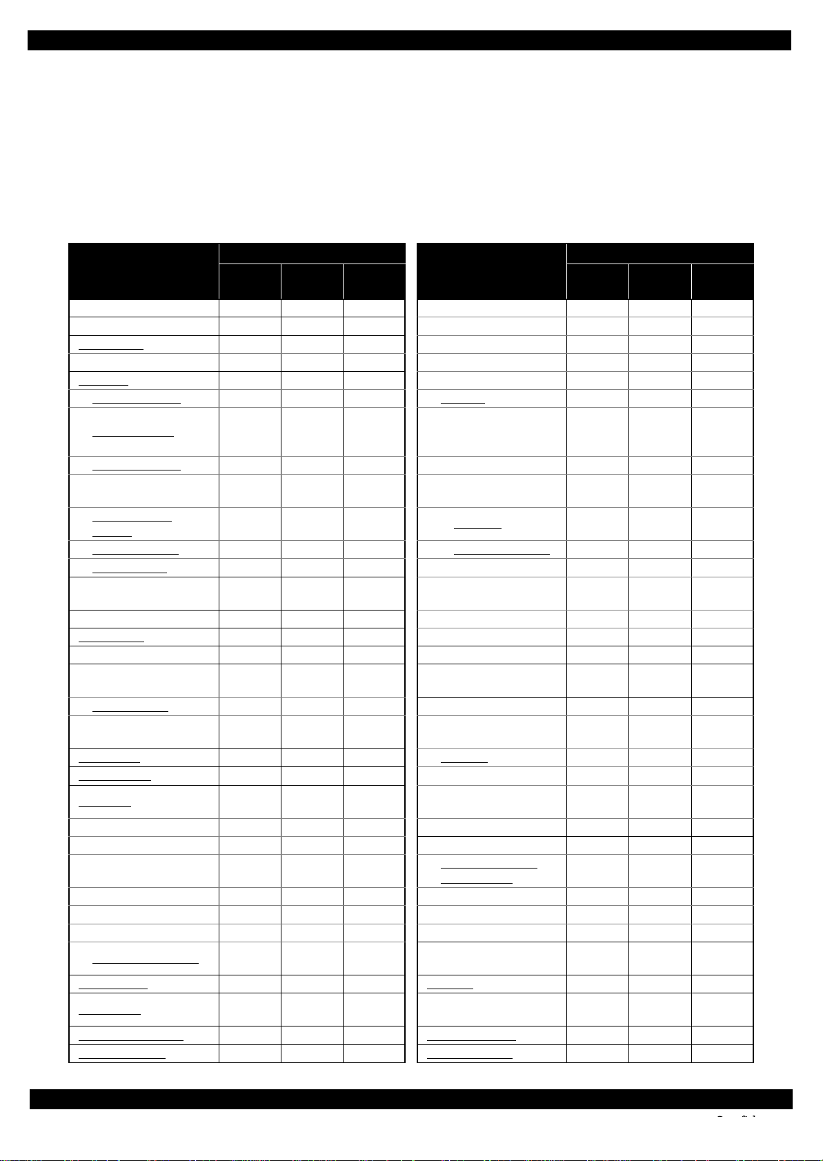
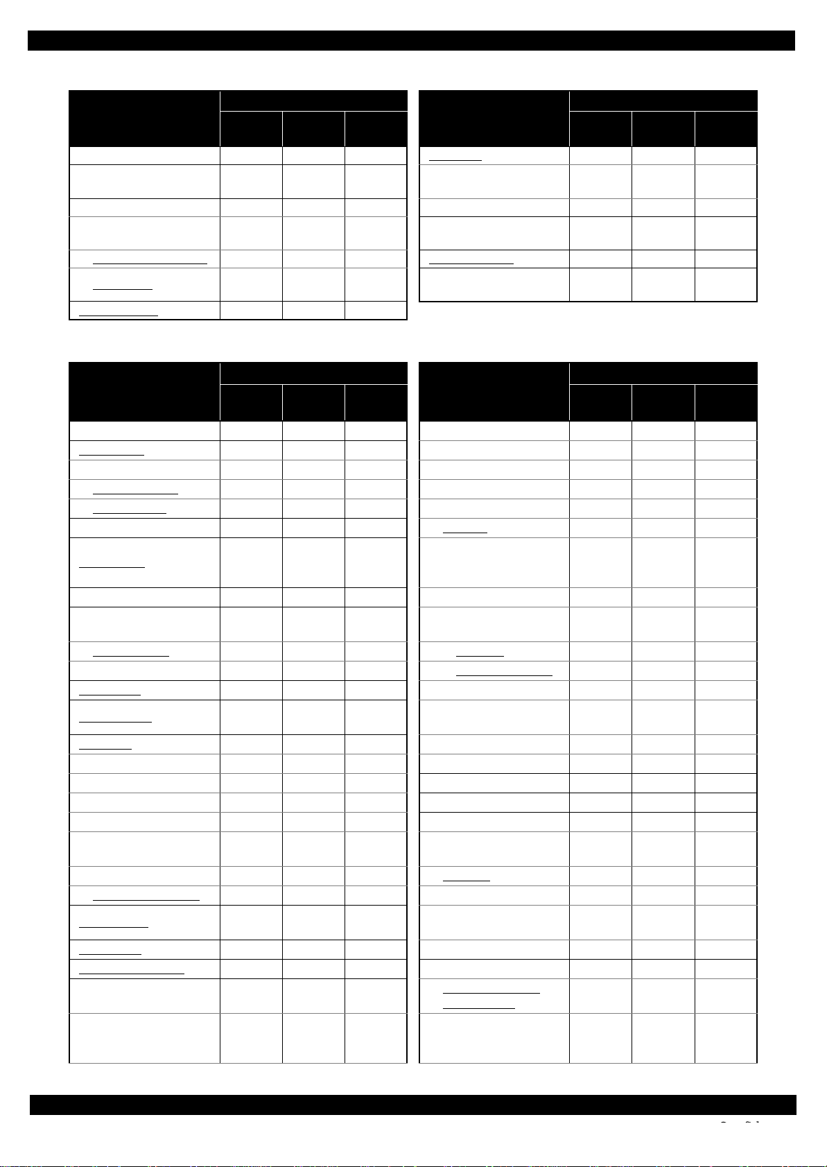
1.2.1 Standard Operation Time for servicing the product (TBD)
The following are the standard operation time for servicing the product. Those are based on the MTTR result
measured using a prototype.
The underlined parts/units are supplied as After Service Parts.
Standard Operation Time for servicing WorkForce 635 series: See Table 1-1
Standard Operation Time for servicing WorkForce 620 series: See Table 1-2
Standard Operation Time for servicing WorkForce 60 series: See Table 1-3
Table 1-1. Standard Operation Time (WorkForce 635 series) (TBD)
Time (second)
Parts/Unit
USB Cover 34 Main Frame (w/ CR Assy) 1134
ADF Unit/Scanner Unit 287 Upper Paper Guide 1150
Scanner Unit
CIS Unit 550 CR Motor 1211
ADF Unit 417 CR Scale Holder 1154
Front ADF Cover 512 CR Assy 1185
Top ADF Cover 514
Right ADF Cover 552 I/C Guide 546
Rear ADF Cover 455
ADF Document
Support
ADF Cover Assy 18 Holder Board Assy 526
ADF Pad Assy 19 CSIC Terminal 577
Document Pad 20
Decoration Plate 57 Holder Board 589
Left Housing
Hinge 300 Front Frame 1167
Upper Housing
(w/ Panel Unit)
Upper Housing 526 Paper Guide Front Assy 1300
Cover Open Sensor 526
Duplex Unit
Right Housing 88 EJ Roller 1216
Panel Unit 225
Panel Gear 230 PF Motor 1406
Panel Lever 230 Frame Base Assy 1300
Lower Panel Housing 333
Panel Board 352 PE Sensor 1352
LCD 394 Stacker Assy 1347
Button 533 Frame Base 1404
Upper Panel Housing 575
Cassette Assy
Pickup Assy 25
Waste Ink Tray Assy
Paper Sheet Assy 12 Extension Spring 566
Replace-
ment
417 PE Holder Assy 1176
429 Printhead 626
88 Head FFC 1216
478 Star Wheel Assy 1193
4 EJ Pulley 1208
4 CR Scale 542
24 Cam Holder Assy 547
Adjust-
ment
Total
Parts/Unit
Hinge Cover
Cartridge/Cartridge
Cover
Inner Head Cable
Cover
CR Contact
Module
Front Paper Guide
Waste Ink Pad
PF Holder/PF Timing
Belt
Lower Paper Guide
Waste Ink Pad
Extension Spring
(Upper Paper Guide)
Driven Pulley/Extension
Spring
Replace-
ment
540
555
538
1431
1334
1305
548
599
Time (second)
Adjust-
ment
Total
Disassembly/Reassembly Disassembly/Reassembly Procedures 13
Confidential
Page 14
Epson WorkForce 635/620/60 series Revision C
Table 1-1. Standard Operation Time (WorkForce 635 series) (TBD)
Time (second)
Parts/Unit
FAX Grounding Plate 559 FAX Assy 643
PF Encoder Sensor 759
Main Board Unit 746 Fax Board 721
Shield Plate
(w/ Wireless LAN Module)
Wireless LAN Module 790 Ink System Assy 570
Main Board 962
P/S Board Assy 538
Replace-
ment
918 Right Frame 517
Adjust-
ment
Total
Parts/Unit
FAX Shield Plate/
FAX Connector Cover
Waste Ink Pad
(Bottom of Ink System Assy)
Replace-
ment
721
575
Time (second)
Adjust-
ment
Total
Table 1-2. Standard Operation Time (WorkForce 620 series) (TBD)
Time (second)
Parts/Unit
USB Cover 34 Main Frame (w/ CR Assy) 897
Scanner Unit 114 Upper Paper Guide 913
CIS Unit 247 PE Holder Assy 939
Document Cover
Document Pad 20 CR Scale Holder 917
Decoration Plate 43 CR Assy 948
Left Housing 74
Hinge 127 I/C Guide 359
Upper Housing
(w/ Panel Unit)
Upper Housing
Cover Open Sensor 339 Holder Board Assy 339
Duplex Unit 4 CSIC Terminal 390
Right Housing 74
Panel Unit 211 Holder Board 385
Panel Gear/Panel Lever 225 Head FFC 979
Lower Panel Housing 324 Front Frame 930
Panel Board 465 Star Wheel Assy 956
LCD 507 Paper Guide Front Assy 1063
LCD Cover 510
Button 554 EJ Pulley 971
Upper Panel Housing 599 EJ Roller 979
Cassette Assy 4
Pickup Assy
Waste Ink Tray Assy 24 Frame Base Assy 1063
Main Board Unit 509
Shield Plate
(w/ Wireless LAN
Module)
Replace-
ment
60 CR Motor 974
322
445 Printhead 439
25 PF Motor 1169
666 PE Sensor 1115
Adjust-
ment
Total
Parts/Unit
Hinge Cover
Cartridge/Cartridge
Cover
Inner Head Cable
Cover
CR Contact
Module
Front Paper Guide
Waste Ink Pad
PF Holder/PF Timing
Belt
Lower Paper Guide
Waste Ink Pad
Replace-
ment
353
368
351
1194
1097
1068
Time (second)
Adjust-
ment
Total
Disassembly/Reassembly Disassembly/Reassembly Procedures 14
Confidential
Page 15
Epson WorkForce 635/620/60 series Revision C
Table 1-2. Standard Operation Time (WorkForce 620 series) (TBD)
Time (second)
Parts/Unit
Wireless LAN Module 553 Stacker Assy 1110
Main Board 666 Frame Base 1167
PF Encoder Sensor 522
Right Frame 330 CR Scale 355
Ink System Assy. 383
Waste Ink Pad
(Bottom of Ink System Assy)
P/S Board Assy 351 Extension Spring 379
Stopper Assy
Replace-
ment
388 Cam Holder Assy 360
Adjust-
ment
Total
Parts/Unit
Extension Spring
(Upper Paper Guide)
Driven Pulley/Extension
Spring
Replace-
ment
361
412
Time (second)
Adjust-
ment
Total
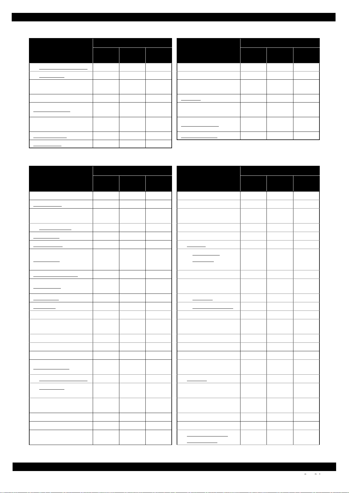
Table 1-3. Standard Operation Time (WorkForce 60 series) (TBD)
Time (second)
Parts/Unit
USB Cover 34 Main Frame (w/ CR Assy) 550
Printer Cover 9 Upper Paper Guide 566
Upper Housing
(w/ Printer Cover)
Upper Housing
Duplex Unit 4 C R Scale Holder 570
Cassette Assy 4 CR Assy 601
Pickup Assy 25
Waste Ink Tray Assy 24 I/C Guide 199
Stacker Assy 128
Front Cover
Panel Unit 44 Holder Board Assy 179
Panel Board 101 CSIC Terminal 230
LED Lens 94
Button 126 Holder Board 242
Front Panel Cover 126 Head FFC 632
Stacker Open Sensor 56 Paper Guide Front Assy 716
Main Board Unit 348
Wireless LAN Module
Shield Plate
(w/ Cover Open Sensor)
Main Board 581
Cover Open Sensor 354 PF Motor 822
PF Encoder Sensor 361 Frame Base Assy 716
Front Frame 583
Replace-
ment
162 PE Holder Assy 592
171 CR Motor 627
13 Printhead 279
392 EJ Pulley 616
581 EJ Roller 624
Adjust-
ment
Total
Parts/Unit
Hinge Cover
Cartridge/Cartridge
Cover
Inner Head Cable
Cover
CR Contact
Module
Front Paper Guide
Waste Ink Pad
PF Holder/PF Timing
Belt
Lower Paper Guide
Waste Ink Pad
Replace-
ment
193
208
191
847
750
721
Time (second)
Adjust-
ment
Total
Disassembly/Reassembly Disassembly/Reassembly Procedures 15
Confidential
Page 16

Epson WorkForce 635/620/60 series Revision C
Table 1-3. Standard Operation Time (WorkForce 60 series) (TBD)
Time (second)
Parts/Unit
Star Wheel Assy 609 PE Sensor 768
CR Scale 195 Frame Base 773
Driven Pulley/Extension
Spring
Right Frame 170 Cam Holder Assy 200
Ink System Assy 223 Extension Spring 219
Waste Ink Pad
(Bottom of Ink System
Assy)
Replace-
ment
252
228 Power Supply Unit 83
Adjust-
ment
Total
Parts/Unit
Extension Spring
(Upper Paper Guide)
Replace-
ment
201
Time (second)
Adjust-
ment
Total
Disassembly/Reassembly Disassembly/Reassembly Procedures 16
Confidential
Page 17
Epson WorkForce 635/620/60 series Revision C
S3
S4
S4
S4
S4
S1
S2
S3
S4
S5
S6
S7
S8S9S10
S11
S12
S13
S14
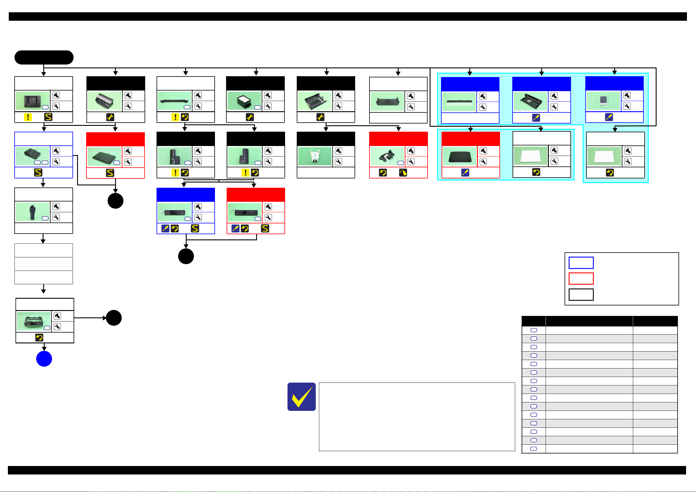
1.2.2 Disassembly/Reassembly Flowchart
1.2.2.1 Housing Part (WorkForce 635 series/WorkForce 620 series)
START
USB Cover
S3
(p 22) (p 28)
ADF Unit/
Scanner Unit
S3 S8
(p 28)
Hinge
S4
---
Decoration Plate
Left Housing
Duplex Unit
1
2
(p 33)
---
---
Scanner Unit
2
---
S3
(p 30)
1
---
Decoration Plate
3
6
(p 22)
Left Housing
1
2
(p 22)
Panel Unit
Waste Ink Tray
Assy
(p 33)
Right Housing
S4
(p 22)
Panel Unit
Cassette Assy
1
4
(p 33)
---
---
Pickup Assy
1
2
---
---
1
Stacker Assy
---
Stopper Assy
S4
(p 26) (p 48)
---
Paper Sheet Assy
---
4
---
1
Document Cover
2
2
(p 22)
---
4
ADF Cover Assy
---
2
(p 25)
Document Pad
---
---
(p 22)
ADF Pad Assy
---
4
(p 25)
Document Pad
---
---
(p 22)
1
1
(p 18)
---
(p 22) (p 28)
3
6
(p 22) (p 29)
3
6
2
(p 18)
WorkForce 635 series specific parts/unit
Right Housing
Upper Housing
(w/ Panel Unit)
S4
(p 22)
A
(p 20)
WorkForce 620 series specific parts/unit
WorkForce 635 series/
WorkForce 620 series common parts/unit
Screw type/torque list
4
---
(p 18)
3
Symbol Screw type Torque
C.B.P-TITE SCREW,2.5X8,F/ZN-3C 4 1 kgf·cm
C.B.P-TITE SCREW,2X8,F/ZN-3C 2 0.5 kgf·cm
C.B.P-TITE SCREW,3X10,F/ZB-3C 6 1 kgf·cm
C.B.P-TITE SCREW,3X10,F/ZN-3C 6 1 kgf·cm
C.B.S-TITE SCREW,3X10,F/ZN-3C 6 1 kgf·cm
C.B.S-TITE SCREW,3X6,F/ZN-3C 4 0.5 kgf·cm
C.B.S-TITE SCREW,3X6,F/ZN-3C 6 1 kgf·cm
See "1.2.2.2Housing Part (WorkForce 60 series) (p19)" for
removing the housing part of WorkForce 60 series.
When replacing the Printer Mechanism supplied as an ASP, make
sure to adjust the Stopper Holder Idle Roller in the proper
attachment position, and then perform the PF Timing Belt tension
measurement. See " Paper Guide Front Assy (Stopper Holder Idle
Roller) (p26)" and "2.2.1PF Timing Belt Tension Measurement/
PF Belt Step Check (p38)" for the details.
C.B.S-TITE SCREW,3X6,F/ZN-3C 8 1 kgf·cm
C.P.SCREW,2.5X6,F/ZN-3C 2 0.5 kgf·cm
C.P.SCREW,3X4,F/ZN-3C 2 0.5 kgf·cm
C.P.SCREW,3X4,F/ZN-3C 4 1 kgf·cm
C.P.SCREW,2.6X3,F/ZN-3C 4 1 kgf·cm
C.B.P-TITE SCREW(S-P1),3X12,F/ZN-3C 5 - 6 kgf·cm
C.B.P-TITE SCREW,2.5X8,F/ZN-3C 2 0.5 kgf·cm
S15
C.B.P-TITE SCREW,3X4,F/ZN-3C 6 1 kgf·cm
Flowchart 1-1. Disassembly Flowchart of Housing Part (1)
Disassembly/Reassembly Disassembly/Reassembly Flowchart 17
Confidential
Page 18
Epson WorkForce 635/620/60 series Revision C
S4
S4
S4
S4
Ref.
S4
S4
S4
S15
(p 17) (p 17)
1 2 3
ADF Unit
(p 25)
Front ADF
Cover
(p 25)
Top ADF Cover
(p 25)
---
---
Scanner Unit
---
3
(p 28)
Rear ADF Cover
3
8
S4
(p 25)
1
3
ADF Document
Support
(p 25)
3
---
2
2
Scanner
(p 28)
CIS Unit
(p 24)
(p 28) (p 47)
---
Panel Gear/
Panel Lever
---
4
---
Lower Panel
Housing
6
2
(p 22)
Panel Board
(p 23)
---
---
Lower Panel
Housing
5
1
(p 22)
6
---
Panel Board
4
8
---
(p 23)
(p 17)
Panel Unit
Upper Housing
---
Cover Open
Sensor
(p 28)
---
---
WorkForce 635 series specific parts/unit
---
2
Right ADF
Cover
1
5
(p 25)
See "1.2.2.2Housing Part (WorkForce 60 series) (p19)" for
removing the housing part of WorkForce 60 series.
When replacing the Printer Mechanism supplied as an ASP, make
sure to adjust the Stopper Holder Idle Roller in the proper
attachment position, and then perform the PF Timing Belt tension
measurement. See " Paper Guide Front Assy (Stopper Holder Idle
Roller) (p26)" and "2.2.1PF Timing Belt Tension Measurement/
PF Belt Step Check (p38)" for the details.
Button
LCD
---
---
---
S2
(p 26)
LCD Cover
---
Upper Panel
Housing
---
---
---
Flowchart 1-2. Disassembly Flowchart of Housing Part (2)
WorkForce 620 series specific parts/unit
Button
WorkForce 635 series/
2
---
---
---
---
Upper Panel
Housing
---
---
---
---
---
Screw type/torque list
Symbol Screw type Torque
S1
C.B.P-TITE SCREW,2.5X8,F/ZN-3C 4 1 kgf·cm
S2
C.B.P-TITE SCREW,2X8,F/ZN-3C 2 0.5 kgf·cm
S3
C.B.P-TITE SCREW,3X10,F/ZB-3C 6 1 kgf·cm
S4
C.B.P-TITE SCREW,3X10,F/ZN-3C 6 1 kgf·cm
S5
C.B.S-TITE SCREW,3X10,F/ZN-3C 6 1 kgf·cm
S6
C.B.S-TITE SCREW,3X6,F/ZN-3C 4 0.5 kgf·cm
S7
C.B.S-TITE SCREW,3X6,F/ZN-3C 6 1 kgf·cm
S8
C.B.S-TITE SCREW,3X6,F/ZN-3C 8 1 kgf·cm
S9
C.P.SCREW,2.5X6,F/ZN-3C 2 0.5 kgf·cm
S10
C.P.SCREW,3X4,F/ZN-3C 2 0.5 kgf·cm
S11
C.P.SCREW,3X4,F/ZN-3C 4 1 kgf·cm
S12
C.P.SCREW,2.6X3,F/ZN-3C 4 1 kgf·cm
S13
C.B.P-TITE SCREW(S-P1),3X12,F/ZN-3C 5 - 6 kgf·cm
S14
C.B.P-TITE SCREW,2.5X8,F/ZN-3C 2 0.5 kgf·cm
WorkForce 620 series common parts/unit
C.B.P-TITE SCREW,3X4,F/ZN-3C 6 1 kgf·cm
Disassembly/Reassembly Disassembly/Reassembly Flowchart 18
Confidential
Page 19

Epson WorkForce 635/620/60 series Revision C
S4
S4
1.2.2.2 Housing Part (WorkForce 60 series)
START
Front Cover
(p 27)
Panel Unit
S4
(p 27)
Stacker Open
Sensor
---
USB Cover
Printer Cover
---
6
---
---
2
Duplex Unit
---
---
(p 33)
Waste Ink Tray
Assy
S3
(p 33)
Cassette Assy
1
4
(p 33)
---
---
Pickup Assy
1
1
---
--1
USB Cover
S4
(p 27)
P/S Board Assy
S4
(p 37)
1
4
1
---
Panel Board
--2
---
LED Lens
3
2
Button
Upper Housing
(w/ Printer Cover)
(p 27)
Cover Open
Sensor
---
A
(p 20)
---
---
WorkForce 635 series specific parts/unit
3
4
---
---
---
Printer Cover
Front Panel Cover
---
---
Stacker Assy
--2
(p 27)
--4
Upper Housing
---
---
---
---
See "1.2.2.1Housing Part (WorkForce 635 series/WorkForce 620 series) (p17)" for
disassembly of the Housing Part of WorkForce 635/620 series.
When replacing the Printer Mechanism supplied as an ASP, make sure to adjust the
Stopper Holder Idle Roller in the proper attachment position, and then perform the PF
Timing Belt tension measurement. See "Paper Guide Front Assy (Stopper Holder Idle
Roller) (p26)" and "2.2.1PF Timing Belt Tension Measurement/PF Belt Step Check
(p38)" for the details.
---
Screw type/torque list
Sym
bol
S1
C.B.P-TITE SCREW,2.5X8,F/ZN-3C 4 1 kgf·cm
S2
C.B.P-TITE SCREW,2X8,F/ZN-3C 2 0.5 kgf·cm
S3
C.B.P-TITE SCREW,3X10,F/ZB-3C 6 1 kgf·cm
S4
C.B.P-TITE SCREW,3X10,F/ZN-3C 6 1 kgf·cm
S5
C.B.S-TITE SCREW,3X10,F/ZN-3C 6 1 kgf·cm
S6
C.B.S-TITE SCREW,3X6,F/ZN-3C 4 0.5 kgf·cm
S7
C.B.S-TITE SCREW,3X6,F/ZN-3C 6 1 kgf·cm
S8
C.B.S-TITE SCREW,3X6,F/ZN-3C 8 1 kgf·cm
S9
C.P.SCREW,2.5X6,F/ZN-3C 2 0.5 kgf·cm
S10
C.P.SCREW,3X4,F/ZN-3C 2 0.5 kgf·cm
S11
C.P.SCREW,3X4,F/ZN-3C 4 1 kgf·cm
S12
C.P.SCREW,2.6X3,F/ZN-3C 4 1 kgf·cm
S13
C.B.P-TITE SCREW(S-P1),3X12,F/ZN-3C 5 - 6 kgf·cm
S14
C.B.P-TITE SCREW,2.5X8,F/ZN-3C 2 0.5 kgf·cm
S15
C.B.P-TITE SCREW,3X4,F/ZN-3C 6 1 kgf·cm
WorkForce 635 series/W orkFor ce 620 series/
WorkForce 60 series common parts/unit
Screw type Torque
Flowchart 1-3. Disassembly Flowchart of Housing Part (3)
Disassembly/Reassembly Disassembly/Reassembly Flowchart 19
Confidential
Page 20

Epson WorkForce 635/620/60 series Revision C
S15
Ref.
Ref.
S4
Ref.
S13
S4
Ref.
S4
S4
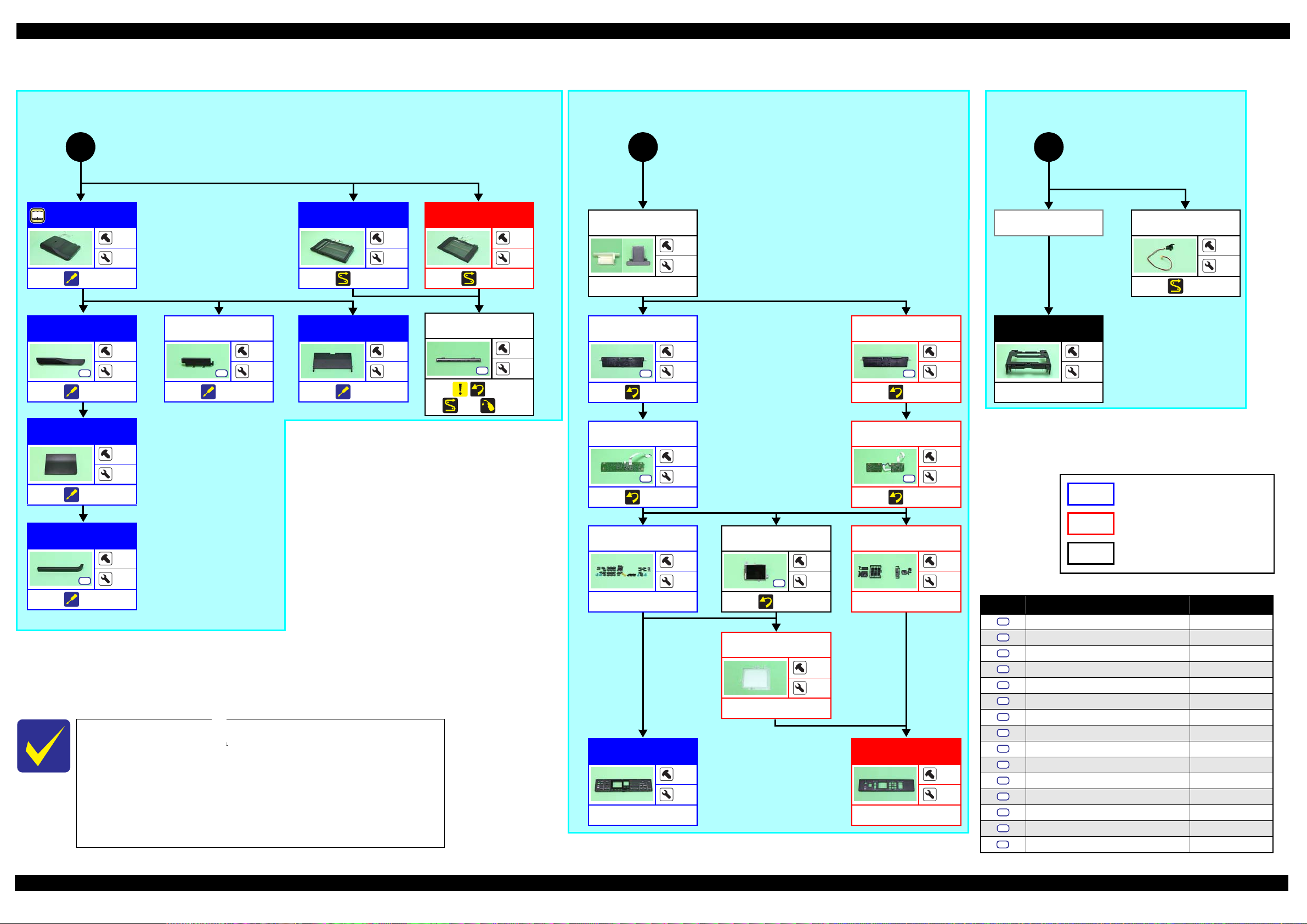
1.2.2.3 Printer Mechanism Part
WorkForce 635 series/WorkForce 620 series:
A
WorkForce 60 series:
FAX Grounding
Plate
S6
---
Main Board Unit
S6
(p 24)
(p 29) (p 33)
Right Frame
Main Frame
(w/ CR Assy)
S4 S8
S13
(p 24)
(p 46) (p 34)
Front Frame
S4
(p 29)
(p 19)
(p 17)
Extension Spring
(Upper Paper Guide)
2
---
CR Scale/
Extension Spring
---
Cam Holder
Assy
Right Frame
---
---
FAX Grounding
Plate
Hinge Cover
Cartridge/
Cartridge Cover
Holder Board
*
Assy
---
P/S Board Assy
1
---
---
6
3
4
2
2
S4
---
1
---
Main Board Unit
3
1
S4 S6
(p 24)
(p 30) (p 33)
4
1
(p 21)
4
4
(p 21)
---
5
(p 23)
Driven Pulley/
Extension Spring
(p 45)
---
---
PF Encoder Sensor
S14
(p 29)
(p 23)
Extension Spring
---
1
---
---
Ink System Assy
---
2
(p 23) (p 46)
Waste In k Pad
(Bottom of Ink
1
1
System Assy)
---
---
---
FAX Assy
S3 S4
(p 28)
FAX Shield Plate/
FAX Connector
Cover
(p 23)
2
---
3
---
---
I/C Guide
---
Inner Head Cable
Cover
---
---
1
---
1
---
CSIC Terminal
---
8
---
Holder Board
---
---
---
Note "*": Only the Hinge Cover Cartridge is supplied as an ASP.
(p 28) (p 37)
CR Contact
Module
---
Main Board Unit
S6
(p 27)
(p 30) (p 33)
---
2
3
(p 21)
2
4
Fax Board
---
Holder Board
Assy
---
---
WorkForce 635 series specific parts/unit
WorkForce 620 series specific parts/unit
WorkForce 60 series specific parts/unit
2
---
WorkForce 635 series/WorkForce 620 series/
WorkForce 60 series common parts/unit
(p 24)
(p 46)
Star Whee l Assy
S4
(p 23) (p 35)
Ink System Assy
Paper Guide
Front Assy
(p 26)
(p 45)
B
(p 21)
(p 35)
2
---
4
---
(p 35)
Printhead
3
S1
(p 24) (p 37)
---
EJ Pulley
---
---
(p 36) (p 46)
When replacing the Printer Mechanism supplied as an ASP, make
(p 21)
6
EJ Roller
---
---
(p 36) (p 45)
sure to adjust the Stopper Holder Idle Roller in the proper attachment
position, and then perform the PF Timing Belt tension measurement.
See " Paper Guide Front Assy (Stopper Holder Idle Roller) (p26)" and
"2.2.1PF Timing Belt Tension Measurement/PF Belt Step Check
(p38)" for the details.
Flowchart 1-4. Disassembly Flowchart of Printer Mechanism Part (1)
Screw type/torque list
Symbol Screw type Torque
S1
C.B.P-TITE SCREW,2.5X8,F/ZN-3C 4 1 kgf·cm
S2
C.B.P-TITE SCREW,2X8,F/ZN-3C 2 0.5 kgf·cm
S3
C.B.P-TITE SCREW,3X10,F/ZB-3C 6 1 kgf·cm
S4
C.B.P-TITE SCREW,3X10,F/ZN-3C 6 1 kgf·cm
S5
C.B.S-TITE SCREW,3X10,F/ZN-3C 6 1 kgf·cm
S6
C.B.S-TITE SCREW,3X6,F/ZN-3C 4 0.5 kgf·cm
S7
C.B.S-TITE SCREW,3X6,F/ZN-3C 6 1 kgf·cm
S8
C.B.S-TITE SCREW,3X6,F/ZN-3C 8 1 kgf·cm
S9
C.P.SCREW,2.5X6,F/ZN-3C 2 0.5 kgf·cm
S10
C.P.SCREW,3X4,F/ZN-3C 2 0.5 kgf·cm
S11
C.P.SCREW,3X4,F/ZN-3C 4 1 kgf·cm
S12
C.P.SCREW,2.6X3,F/ZN-3C 4 1 kgf·cm
S13
C.B.P-TITE SCREW(S-P1),3X12,F/ZN-3C 5 - 6 kgf·cm
S14
C.B.P-TITE SCREW,2.5X8,F/ZN-3C 2 0.5 kgf·cm
C.B.P-TITE SCREW,3X4,F/ZN-3C 6 1 kgf·cm
Disassembly/Reassembly Disassembly/Reassembly Flowchart 20
Confidential
Page 21

Epson WorkForce 635/620/60 series Revision C
S1S2S3
S4
S5
S6
S7
S8
S9
S10
S11
S12
S13
S14
S12
S5
S10
S9
S7
S10
S7
(p 20)
B
Waste Ink Tray
Assy
Cassette Assy
Pickup Assy
P/S Board Assy
Waste In k Pad
(Bottom of Ink
System Assy)
FAX Assy
Frame Base
*2*3
Assy
(p 36)
WorkForce 635 series/WorkForce 620 series:
4
WorkForce 60 series:
Shield Plate
(w/ Wireless LAN
Module)
S7
(p 23)
Main Board
*1
(p 33)
---
---
---
(p 20)
Shield Plate
(w/ Wireless LAN
Module)
7
S5
(p 23)
6
---
(p 20)
Wireless LAN
Module
(p 23)
*5
(p 20)
5
Upper Paper
Guide
2
---
(p 34)
---
6
PE Holder Assy
1
S8
(p 34)
---
CR Scale Holder
S8
---
Hinge Cover
Cartridge/
Cartridge Cover
I/C Guide
Inner Head Cable
Cover
CR Motor
1
---
S11
(p 28) (p 34)
2
---
Stopper Holder/
Idle Roller
6
EJ Pulley
EJ Roller
S15
---
(p 20)
---
Front Paper Gu ide
Waste Ink Pad
---
---
(p 26)
1
Holder Board
Assy
Printhead
PF Holder/
PF Timing Belt
---
CR Motor
(p 36) (p 45)
---
---
CR Assy
---
PF Motor
---
(p 35) (p 46)
1
2
---
Stacker Assy
Frame Base
(p 36)
*4
Lower Paper Guide
Waste Ink Pad
(p 37)
---
---
PE Sensor
(p 29) (p 37)
---
Head FFC
4
---
---
(p 29)
(p 29) (p 36)
Screw type/torque list
Symbol Screw type Torque
C.B.P-TITE SCREW,2.5X8,F/ZN-3C 4 1 kgf·cm
C.B.P-TITE SCREW,2X8,F/ZN-3C 2 0.5 kgf·cm
C.B.P-TITE SCREW,3X10,F/ZB-3C 6 1 kgf·cm
*3
Note "*1": Supplied as an ASP only for WorkForce 635 series/WorkForce 620 series.
---
---
"*2": Supplied as an ASP only for WorkForce 635 series/WorkForce 60 series.
"*3": The shape of the parts are different but the procedure is the same between
WorkForce 635 series/WorkForce 620 series and WorkForce 60 series.
"*4": See (p 19) for Stacker Assy of WorkForce 60 series.
"*5": This is not mounted on Epson ME OFFICE 85ND.
When replacing the Printer Mechanism supplied as an ASP, make
WorkForce 635 series specific parts/unit
WorkForce 620 series specific parts/unit
sure to adjust the Stopper Holder Idle Roller in the proper attachment
position, and then perform the PF Timing Belt tension measurement.
WorkForce 60 series specific parts/unit
See " Paper Guide Front Assy (Stopper Holder Idle Roller) (p26)" and
"2.2.1PF Timing Belt Tension Measurement/PF Belt Step Check
WorkFor ce 635 series/WorkForce 620 series/
WorkForce 60 series common parts/unit
(p38)" for the details.
C.B.P-TITE SCREW,3X10,F/ZN-3C 6 1 kgf·cm
C.B.S-TITE SCREW,3X10,F/ZN-3C 6 1 kgf·cm
C.B.S-TITE SCREW,3X6,F/ZN-3C 4 0.5 kgf·cm
C.B.S-TITE SCREW,3X6,F/ZN-3C 6 1 kgf·cm
C.B.S-TITE SCREW,3X6,F/ZN-3C 8 1 kgf·cm
C.P.SCREW,2.5X6,F/ZN-3C 2 0.5 kgf·cm
C.P.SCREW,3X4,F/ZN-3C 2 0.5 kgf·cm
C.P.SCREW,3X4,F/ZN-3C 4 1 kgf·cm
C.P.SCREW,2.6X3,F/ZN-3C 4 1 kgf·cm
C.B.P-TITE SCREW(S-P1),3X12,F/ZN-3C 5 - 6 kgf·cm
C.B.P-TITE SCREW,2.5X8,F/ZN-3C 2 0.5 kgf·cm
S15
C.B.P-TITE SCREW,3X4,F/ZN-3C 6 1 kgf·cm
Flowchart 1-5. Disassembly Flowchart of Printer Mechanism Part (2)
Disassembly/Reassembly Disassembly/Reassembly Flowchart 21
Confidential
Page 22

Epson WorkForce 635/620/60 series Revision C
Hook
Rib
C.B.P-TITE SCREW,3X10,F/ZB-3C (6 ± 1 kgf·cm)
USB Cover
Decoration Plate
Hook
C.B.P-TITE SCREW,3X10,F/ZN-3C (6 ± 1 kgf·cm)
Decoration Plate
1
2
3
No gap
ADF Unit (WorkForce 635 series)
Document Cover (WorkForce 620 series)
Reference position
Document Pad
Standard line
Double-sided tape
No gap
Right Housing
Left Housing
Hole
Rib
Positioning
hole
Dowel
Left
Panel FFC
Cover Open Sensor cable
Right
Document Cover
Dowel
Upper Housing
3
1
2
Panel Shaft HolderLeft
Hook
Right
Panel Shaft Holder
C.B.P-TITE SCREW,3X10,F/ZN-3C (6 ± 1 kgf·cm)
Panel Unit
C.B.P-TITE SCREW,3X10,F/ZN-3C (6 ± 1 kgf·cm)
1
2
3
4
Upper Housing
Panel Unit
3
1
5
4
6
2
WorkForce 635 series
Lower Panel Housing
3
1
5
4
2
6
WorkForce 620 series
Lower Panel Housing
C.B.P-TITE SCREW,3X10,F/ZN-3C (6 ± 1 kgf·cm)
1.3 Detailed Disassembly/Reassembly Procedure for each Part/Unit
USB Cover (WorkForce 635/620 series)
Remove the USB Cover by sliding it in the direction of the arrow
shown above carefully not to damage the hooks (x2) that secure the
USB Cover.
Decoration Plate (WorkForce 635/620 series)
Remove the Decoration Plate by rotating it in the direction of the
arrow shown above carefully not to damage the hooks (x2) that
secure the Decoration Plate.
Tighten the screws in the order indicated in the figure above.
Document Pad (WorkForce 635/620 series)
First align one bottom corner of the Document Pad with the
reference position and attach it with double-sided tape.
Make sure there is no gap on the left and bottom sides of the
Document Pad.
Left Housing/Right Housing (WorkForce 635/620 series)
Be careful not to damage the hooks (x1 each) and ribs (x7
each) that secure the Left Housing/Right Housing.
Be careful to remove the Left Housing since the Panel FFC and
the Cover Open Sensor cable are routed inside it.
When installing the Left/Right Housing, align the positioning holes
with the dowels of the Upper Housing.
Document Cover (WorkForce 620 series)
Panel Unit (WorkForce 635/620 series)
Upper Housing (w/ Panel Unit)
Lower Panel Housing (WorkForce 635/620 series)
(WorkForce 635/620 series)
When removing the Document Cover, follow the procedure below.
1. With the Document Cover open, release the outside dowel on
the right by pushing it from the rear of the printer.
2. Release the outside dowel on the left, and remove the
Document Cover.
Disassembly/Reassembly Detailed Disassembly/Reassembly Procedure for each Part/Unit 22
Remove the screws (x3) with the Panel Unit open, and turn the
Panel Unit in the direction of the arrow to release the hooks of the
Panel Shaft Holders from the Upper Housing, then remove the
Panel Unit.
Secure the hooks of the Panel Shaft Holders firmly to the Upper
Housing, and tighten the screws in the order indicated in the figure
above.
Tighten the screws in the order indicated in the figure above.
Tighten the screws in the order indicated in the figure above.
Confidential
Page 23

Epson WorkForce 635/620/60 series Revision C
1
2
Panel Board
WorkForce 635 series
3
4
1 2
34
5 6
78
Panel Board
WorkForce 620 series
C.B.P-TITE SCREW,3X10,F/ZN-3C (6 ± 1 kgf·cm)
CR Scale
Extension spring
Hook
Cut section
Longer leg
Cam Holder Assy
D/E Lever
Protrusion
Groove
8 ± 1 mm
Hole of Frame Base
Waste Ink Tube
Waste Ink Tube
2
1
3
FAX Shield Plate
FAX Connector Cover
C.B.P-TITE SCREW,3X10,F/ZN-3C (6 ± 1 kgf·cm)
Grounding Spring
Star Wheel Assy
Left
Rib
7
5
WorkForce
635 series only
6
C.B.S-TITE SCREW,3X6,F/ZN-3C (6 ± 1 kgf·cm)
1
2
3
4
C.P SCREW,2.5X6,F/ZN-3C (2 ± 0.5 kgf·cm)
C.P-SCREW,3X4,F/ZN-3C (2 ± 0.5 kgf·cm)
C.B.S-TITE SCREW,3X10,F/ZN-3C (6 ± 1 kgf·cm)
1
2
WorkForce 635 series
1
2
WorkForce 620 series
WorkForce 60 series
C.B.S-TITE SCREW,3X6,F/ZN-3C (6 ± 1 kgf·cm)
Panel Board (WorkForce 635/620 series)
CR Scale/Extension Spring
Cam Holder Assy
Ink System Assy
Tighten the screws in the order indicated in the figure above.
FAX Shield Plate/FAX Connector Cover
(WorkForce 635 series)
Install the CR Scale with the cut section up.
Attach it to the hook on the left of the printer with the longer
leg of the extension spring to the front of the printer.
Star Wheel Assy
When installing the Cam Holder Assy, insert the protrusion of the
D/E Lever into the groove of the Cam Holder Assy.
Shield Plate (w/ Wireless LAN Module)
(WorkForce 635/620 series)
When installing the Ink System Assy, insert the Waste Ink Tube
(8 ± 1 mm from the tip) into the hole on the Frame Base.
Wireless LAN Module
Disassembly/Reassembly Detailed Disassembly/Reassembly Procedure for each Part/Unit 23
Tighten the screws in the order indicated in the figure above.
Hook the leg of the grounding spring to the rib and attach the
Tighten the screws in the order indicated in the figure above.
Tighten the screws in the order indicated in the figure above.
spring as shown in the figure above.
Confidential
Page 24

Epson WorkForce 635/620/60 series Revision C
PF Encoder Cover
Double-sided
tape
(27 x 4 mm)
MAC Address Label
C.B.P-TITE SCREW,3X10,F/ZN-3C (6 ± 1 kgf·cm)
2
1
3
C.B.S-TITE SCREW,3X6,F/ZN-3C (4 ± 0.5 kgf·cm)
PF Encoder Cover
Rib
Screw hole
Main Board Unit
Main Board Unit
Timing Belt
Belt clamp
Torsion spring
Spacer
Label
CIS Carriage
Cutout
Bottom of Front Frame
1.6 mm
1.6 mm
Antistatic cloth Antistatic cloth
1
2
C.B.P-TITE SCREW,3X10,F/ZN-3C (6 ± 1 kgf·cm)
Front Frame
Right
Left
D/E Lever
Cutout
Rear
Nozzle plate surface
of Printhead
Main Frame
Main Frame
C.B.P-TITE SCREW,3X10,F/ZN-3C (6 ± 1 kgf·cm)
C.B.S-TITE SCREW,3X6,F/ZN-3C (8 ± 1 kgf·cm)
C.B.P-TITE SCREW(S-P1),3X12,F/ZN-3C (5 - 6 kgf·cm)
1 2
3
C.B.P-TITE SCREW,2.5X8,F/ZN-3C (4 ± 1 kgf·cm)
Printhead
Step 2-3
Printhead supporting tool
Rear
Carriage
Step 1
Printhead supporting tool
Main Board Unit (WorkForce 635/620 series)
Do not damage or contaminate the MAC Address Label.
Align the rib (x1) and screw hole of the PF Encoder Cover with the Main Board Unit as shown above, and secure the PF Encoder Cover with
double-sided tape (x1).
Tighten the screws in the order indicated in the figure above.
When replacing the Main Board, it is necessary to set the MAC address if the EEPROM data cannot be read out from the old Main Board. In such
a case, refer to "2.2.3MAC Address Setting (p42)" and set it.
CIS Unit (WorkForce 635/620 series)
Confirm the label of the CIS Unit, and make sure to install the
proper spacers on both ends of the CIS Unit corresponding to the
label.
• A: Spacer, CIS, A17 (black)
• B: Spacer, CIS, B19 (white)
• C: Spacer, CIS, C21 (gray)
When installing the Timing Belt, secure the Timing Belt and
the CIS Carriage with the Belt Clamp, and attach the torsion
spring to the location shown above.
Front Frame
Tighten the screws in the order indicated in the figure above.
When attaching the antistatic cloth, make sure to follow the
standard below and attach it to the Front Frame.
• Align the antistatic cloth with the edge of the cutout on the
bottom of the Front Frame.
• Attach it at 1.6 mm away from the edge of the Front Frame.
Main Frame (w/ CR Assy)
When removing the Main Frame with the Printhead installed on the Carriage, be careful not to damage the nozzle plate surface of the Printhead.
When removing the Main Frame, follow the procedure below.
1. Slide the D/E Lever toward the 0-digit side to align the D/E Le ver with the cutout of the Main Frame, and detach the D/E Lever from the Main Frame.
2. Release the CR Motor cable from the hooks of the Main Frame and ribs of the Frame Base. (See "CR Motor (p28)".)
3. Release the Head FFC from the ribs of the Front Frame. (See "Head FFC (p29)".)
4. Remove the screws (x4) that secure the Main Frame, and remove the Main Frame from the Frame Base.
Disassembly/Reassembly Detailed Disassembly/Reassembly Procedure for each Part/Unit 24
When installing the Printhead, use the printhead supporting tools (x2) and follow the procedure below.
1. Move the carriage to the center, and from the rear of the printer, insert the supporting tools one each on the 0-digit side and 80-digit side until
they touch the Main Frame.
2. Move the carriage toward the 80-digit side to the end, and install the Printhead to the carriage.
3. Tighten the screws in the order indicated in the figure above.
Printhead
Confidential
Page 25

Epson WorkForce 635/620/60 series Revision C
Rear ADF Cover
ADF Cover Assy
Top ADF Cover
ADF Unit
Hook
Dowel
Screw hole
Front ADF Cover
Release hooks that secure Front ADF Cover in the direction of the arrow.
Front ADF Cover
ADF Pad Assy
ADF Document Support
ADF Unit
Hook
Dowel
Screw hole
Right ADF Cover
Release hooks that secure Right ADF Cover in the direction of the arrow.
Right ADF Cover
ADF Unit (WorkForce 635 series) (1)
ADF Unit (WorkForce 635 series) (2)
Disassembly/Reassembly Detailed Disassembly/Reassembly Procedure for each Part/Unit 25
The figures above indicate the hooks, dowels and screws that secure the parts and units.
The figures above indicate the hooks, dowels and screws that secure the parts and units.
Confidential
Page 26

Epson WorkForce 635/620/60 series Revision C
C
C
B
A
C
A
Fig. 2: Tool position (80-digit side)
Paper Guide Front Assy
Frame Base
1
3
4
2
C.B.P-TITE SCREW(S-P1),3X12,F/ZN-3C (5 - 6 kgf·cm)
Fig. 3: Screws tightening order
Paper Guide Front Assy
B
C
C
C
Fig. 1: Tool positions (bottom)
Paper guide front
supporting tools
for WorkForce 635
series/WorkForce
60 series
224 mm
123 mm119 mm
186 mm
Front of printer
Paper guide front
supporting tools
for WorkForc e 620
series
89.5 mm
315 mm
Insert the tools into hole of Frame Base.
87 mm
When installing the Paper Guide Front Assy,
use the paper guide front supporting tools (x4)
and follow the procedure below.
1. On a flat table, put the paper guide front
supporting tools B and C on the positions
shown in Fig. 1.
2. Put the Frame Base over the
paper guide front
supporting tools B and C, and confirm that the
tools are placed on the correct positions.
3. Install the Paper Guide Front Assy to the
Frame Base.
4. Put the
paper guide front supporting tool A on
the position shown in Fig. 2.
5. Tighten the screws (x4) in the order
indicated in Fig. 3 to secure the Paper Guide
Front Assy.
6. After securing the Paper Guide Front Assy,
install the PF Holder and the Stopper Holder
Idle Roller. (See "Paper Guide Front Assy
(Stopper Holder Idle Roller) (p26)".)
7. Perform "2.2.1PF Timing Belt Tension
Measurement/PF Belt Step Check (p38)".
Left
Stopper Holder Idle Roller
PF Timing Belt
C.B.S-TITE SCREW,3X4,F/ZN-3C (6 ± 1 kgf·cm)
PF Holder
Less than 0.3 mm
1
2
LCD
C.B.P-TITE SCREW,2X8,F/ZN-3C (2 ± 0.5 kgf·cm)
Leg of Front Paper Guide Waste Ink Pad
Bottom of Paper Guide Front Assy
Front Paper Guide Waste Ink Pad Paper Guide Front Assy
Dowel
Cam slider
Slider base
Stopper
Compression spring
Extension spring
Stopper lever
Paper Guide Front Assy (installation using the tools)
A B C
12.5 mm
A B C
12.5 mm
45.5 mm
20 mm
20 mm
8 mm
34.5 mm
8 mm
15 mm
15 mm
44 mm
33 mm
33 mm
33 mm
45 mm
33 mm
34 mm
33 mm
Paper Guide Front Assy (Stopper Holder Idle Roller)
LCD (WorkForce 635/620 series)
Attach the Stopper Holder Idle Roller so that the gap between it
and the PF Holder becomes less than 0.3 mm.
If the gap becomes larger than 0.3 mm, replace the Stopper Holder
Idle Roller with the longer one (the following “1”) or the longest
one (the following “2”) one by one to until proper gap is obtained.
1. Stopper Holder Idle Roller, PF;C (Parts code: 1540328)
Tighten the screws in the order indicated in the figure above.
2. Stopper Holder Idle Roller, PF;B (Parts code: 1540006)
Front Paper Guide Waste Ink Pad
Stopper Assy (WorkForce 620 series)
Disassembly/Reassembly Detailed Disassembly/Reassembly Procedure for each Part/Unit 26
Install the Front Paper Guide Waste Ink Pad under the ribs
(x12) of the Paper Guide Front Assy without any gap.
After installing the Front Paper Guide Waste Ink Pad, check if
all the legs of the Front Paper Guide Waste Ink Pad come out
from the holes of the Paper Guide Front Assy correctly.
If any of the parts of the Stopper Assy comes off when removing it,
be sure to assemble the Stopper Assy as shown above.
Confidential
Page 27

Epson WorkForce 635/620/60 series Revision C
Hook
Rib
Front Cover
Back of Front Cover
Screw boss
Hooks
Rib
USB Cover
C.B.P-TITE SCREW,3X10,F/ZN-3C (6 ± 1 kgf·cm)
4
3
2
1
Upper Housing
C.B.P-TITE SCREW,3X10,F/ZN-3C (6 ± 1 kgf·cm)
Panel Unit
Stacker Open Sensor
Groove
Stacker Open Sensor
C.B.P-TITE SCREW,3X10,F/ZN-3C (6 ± 1 kgf·cm)
Stacker Lock
Stacker Assy
Bottom
Hooks to secure
Stacker Lock
Stacker Assy
Shaft & bearing
Frame Base
Step 1-2
Step 3
Positioning
hole
Rib
PF Encoder Cover
MAC Address Label
C.B.P-TITE SCREW,3X10,F/ZN-3C (6 ± 1 kgf·cm)
2
1
3
C.B.S-TITE SCREW,3X6,F/ZN-3C (6 ± 1 kgf·cm)
C.B.S-TITE SCREW,3X6,F/ZN-3C (4 ± 0.5 kgf·cm)
4
Cutout
Dowel
Main Board Unit
PF Encoder Cover
Front Cover (WorkForce 60 series)
USB Cover (WorkForce 60 series)
Upper Housing (WorkForce 60 series)
Panel Unit (WorkForce 60 series)
Be careful not to damage the hooks (x2) and ribs (x4) that secure
the Front Cover.
Stacker Assy (WorkForce 60 series)
Remove the USB Cover in the direction of the arrow. Be careful
not to damage the hooks (x2), rib (x1) and screw boss (x1) then.
Tighten the screws in the order indicated in the figure above.
Main Board Unit (WorkForce 60 series)
When installing the Panel Unit, route the cable of the Stacker Open
Sensor through the groove of the Upper Housing so as not to catch
the cables in between.
Follow the procedure below when removing the Stacker Assy.
1. Release the hooks (x2) that secure the Stacker Lock, and lift the Stacker Lock in the direction of the arrow.
Disassembly/Reassembly Detailed Disassembly/Reassembly Procedure for each Part/Unit 27
2. Remove the Stacker Lock from the shaft on the left of the Stacker Assy.
3. Remove the shaft on the right of the Stacker Assy from the bearing of the Frame Base, and remove the Stacker Assy from the Frame Base.
Do not damage or contaminate the MAC Address Label.
Align the rib (x1) and positioning hole (x1) of the PF Encoder Cover with the cutout (x1) and dowel (x1) of the Frame Base.
Tighten the screws in the order indicated in the figure above.
When replacing the Main Board, it is necessary to set the MAC address if the EEPROM data cannot be read out from the old Main Board. In such
a case, refer to "2.2.3MAC Address Setting (p42)" and set it.
Confidential
Page 28

Epson WorkForce 635/620/60 series Revision C
Double-sided tape
Scanner FFC
Ferrite core
C.B.P-TITE SCREW,3X10,F/ZN-3C (6 ± 1 kgf·cm)
FAX Assy
Grounding
wire
CN24
CN19
CN2
CN18
CN22
CN17
Main Board
Scanner FFC
Route FFC through hole
with its stiffener outward.
Rear
Front
Panel FFC
Groove
Rib
Hole
Panel FFC
Panel Unit
Cover Open Sensor
Cover Open Sensor cable
Groove of Upper Housing
Scanner Motor cable
Dowel
Groove
Scanner FFC
Double-sided tape
Screw boss
P/S Board Assy cable
Ferrite core
P/S Board Assy cable
Section A
P/S Board Assy
CR Motor cable
2 mm or less
Main Frame
Hook
Rib
CR Motor cable
CR Motor
Groove of PF Encoder Cover
Ferrite core
Back of PF Encoder Cover
FAX FFC
CN3
PF Encoder Cover
FAX Assy
Main Board
1.4 Routing FFCs/cables
Inside the USB Cover (WorkForce 635 series)
When routing the FFCs/cables inside the USB Cover, connect them to the Main Board as shown above.
• ADF PE Sensor cable (CN18) • ADF Encoder cable (CN19)
• ADF Document Sensor cable (CN22) • ADF Motor cable (CN24)
• Scanner Motor cable (CN2)
• Scanner FFC (CN17): Secure the ferrite core to the Upper Housing with double-sided tape.
• Grounding wire: Secure to the FAX Assy with screw.
Panel Unit (WorkForce 635 series)
When routing the Panel FFC, be careful of the following.
Route it through the rib, groove and hole of the Upper Housing as shown
above.
Facing the FFC stiffener outward, route it through the hole of the Upper
Housing.
Cover Open Sensor (WorkForce 635/620 series)
Route the Cover Open Sensor cable through the groove of the Upper Housing.
Scanner FFC/Scanner Motor Cable
P/S Board Assy (WorkForce 635/620 series)
CR Motor
FAX Assy (WorkForce 635 series)
(WorkForce 635/620 series)
When routing the Scanner FFC, secure it to the housing with double-sided
tape (x3).
When routing the Scanner Motor cable, route it through the dowels (x2)
and groove of the housing.
Disassembly/Reassembly Routing FFCs/cables 28
When routing the P/S Board Assy cable, make sure of the following.
Insert the ferrite core into the section A of the Frame Base.
Route the P/S Board Assy cable between the screw boss and P/S Board
Assy in order to prevent the cable from getting caught.
When routing the CR Motor cable, route it through the hooks (x7) and ribs
(x2) as shown above.
Make sure the gap between the CR Motor cable and the Main Frame is
less than 2 mm.
When routing the FAX FFC, insert the ferrite core into the groove of the PF
Encoder Cover, and connect the FFC to the Main Board.
Confidential
Page 29

Epson WorkForce 635/620/60 series Revision C
Head FFC
Carriage
To CR Encoder
To Holder Board Assy
Rib
Front Frame
Head FFC
Rib
Ferrite core
Head FFC
Double-sided tape
Head FFC
CN11
CN12
CN13
Bottom of Main Board Unit
Rib
PF Motor cable
CN7CN6
CN15
CN501
CN3
FAX FFC
CN14
Cutout of PF
Encoder Cover
PF Encoder FFC
CR Motor cable
P/S Board Assy cable
PF Motor cableCR Motor cable
PF Encoder FFC
PF Encoder Cover
Rib
Main Board
Bottom of Paper Guide Front Assy
Hook A
PF Motor cable
PF Motor
Hook
PE Sensor cable
PE Sensor
Hole
Boss
Hook
Rib A
Rib B
Route FFC through hole
with its terminal outward.
Rib
Groove
Hole
Rear
Front
Panel FFC
Panel FFC
Panel Unit
Head FFC
When you do not need to replace the Head FFC, be careful not to disconnect it from the CR encoder connector. Once it is disconnected, you must
disassemble the carriage to reconnect it to the CR encoder.
Confirm that the Head FFC is connected to the CR Contact Module and CR Encoder.
Route the Head FFC through the ribs (x3) of the Carriage.
Route the Head FFC through the ribs (x4) of the Front Frame.
Main Board (WorkForce 635 series)
When connecting the following cables to the Main Board, connect them as shown above.
Head FFC (CN11, CN12, CN13): Secure the ferrite core to the Main Board with double-sided tape, and connect it confirming the direction of the
terminals is correct.
PF Motor cable (CN7): Route it through the ribs (x4) of the Frame Base, and connect it to the connector on the Main Board.
CR Motor cable (CN6): Route it through the cutout of the PF Encoder Cover, and connect it to the connector on the Main Board. See "CR
Motor (p28)" for routing it on the other sections.
PE Sensor cable (CN15): Route it through the cutout of the PF Encoder Cover, and connect it to the connector on the Main Board. See "PE
Sensor (p29)" for routing it on the other sections.
PF Encoder FFC (CN14): See "PF Encoder Sensor (WorkForce 635/620 series) (p29)".
FAX FFC (CN3): See "FAX Assy (WorkForce 635 series) (p28)".
P/S Board Assy cable (CN501): See "P/S Board Assy (WorkForce 635/620 series) (p28)".
PF Encoder Sensor (WorkForce 635/620 series)
Route the PF Encoder FFC through the ribs of the PF Encoder Cover, and
connect it to the Main Board.
Route the PF Motor cable through the hooks (x2) of the Paper Guide Front
Assy. Make one turn in the direction of the arrow around the hook A.
PF Motor
PE Sensor
Route the PE Sensor cable through the hole of the Frame Base, and route
it through the bosses (x2), hook (x1), and rib A (x1).
When routing the PE Sensor cable, keep it below the rib B.
Panel Unit (WorkForce 620 series)
When routing the Panel FFC, be careful of the following.
Route it through the rib, groove and hole of the Upper Housing as shown
above.
Facing the FFC terminal outward, route it through the hole of the Upper
Housing.
Disassembly/Reassembly Routing FFCs/cables 29
Confidential
Page 30

Epson WorkForce 635/620/60 series Revision C
Double-sided tape
Scanner FFC
Ferrite core
CN8
Main Board
CN17
Scanner FFC
Scanner Motor cable
Ferrite core
Head FFC
Double-sided tape
Head FFC
CN11
CN12
CN13
Bottom of Main Board Unit
PF Motor cable
Rib
CN15
CN7
CN6
CN501
CN14
PF Encoder FFC
CR Motor Cable
PE Sensor cable
PF Motor cable
P/S Board Assy cable
Cutout of PF
Encoder Cover
Rib
PF Encoder Cover
PF Encoder FFC
CR Motor Cable
PE Sensor cable
PF Motor cable
Ferrite core of P/S
Board Assy cable
Bottom of Main Board Unit
Panel FFCCN5
CN7
CN6
CN501
CN15
CN14
Double-sided tape
Ferrite core of Head FFC
CN11
CN12
Head FFC
CN13
Inside the USB Cover (WorkForce 620 series)
When routing the FFCs/cables inside the USB Cover, connect them to the Main Board as shown above.
• Scanner Motor cable (CN8)
• Scanner FFC (CN17): Secure the ferrite core to the Upper Housing with double-sided tape.
Main Board (WorkForce 620 series)
When connecting the following cables to the Main Board, connect them as shown above.
Head FFC (CN11, CN12, CN13): Secure the ferrite core to the Main Board with double-sided tape, and connect it confirming the direction of the
terminals is correct.
PF Motor cable (CN7): Route it through the ribs (x4) of the Frame Base, and connect it to the connector on the Main Board.
CR Motor cable (CN6): Route it through the cutout of the PF Encoder Cover, and connect it to the connector on the Main Board. See "CR
Motor (p28)" for routing it on the other sections.
PE Sensor cable (CN15): Route it through the cutout of the PF Encoder Cover, and connect it to the connector on the Main Board. See "PE
Sensor (p29)" for routing it on the other sections.
PF Encoder FFC (CN14): See "PF Encoder Sensor (WorkForce 635/620 series) (p29)".
P/S Board Assy cable (CN501): See "P/S Board Assy (WorkForce 635/620 series) (p28)".
Main Board (WorkForce 60 series)
When connecting the following cables to the Main Board, connect them as shown above.
Head FFC (CN11, CN12, CN13): Secure the ferrite core to the Main Board with double-sided tape, and connect it confirming the direction of the
Panel FFC (CN5): Connect it to the Main Board confirming the direction of the terminals is correct.
PF Motor cable (CN7): Route it as shown in the above, and connect it to the Main Board.
CR Motor Cable (CN6): Route it through the ribs (x2) of the PF Encoder Cover, and connect it to the connector on the Main Board. See "CR
PE Sensor cable (CN15): Route it through the ribs (x2) of the PF Encoder Cover, and connect it to the connector on the Main Board. See "PE
PF Encoder FFC (CN14): Route it through the ribs (x1) of the PF Encoder Cover, and connect it to the connector on the Main Board.
P/S Board Assy cable (CN501): Insert the ferrite core into the position shown above, and connect it to the connector on the Main Board.
Disassembly/Reassembly Routing FFCs/cables 30
terminals is correct.
Motor (p28)" for routing it on the other sections.
Sensor (p29)" for routing it on the other sections.
Confidential
Page 31

CHAPTER 2
ADJUSTMENT
Confidential
Page 32

Epson WorkForce 635/620/60 series Revision C
2.1 Required Adjustments
The table from the following page lists the required adjustments depending upon the parts being repaired or
replaced. Find the part(s) you removed or replaced, and check which adjustment(s) must be carried out.
If the EEPROM data cannot be read out from the old Main Board using the Adjustment
Program when replacing the Main Board is required, the Waste Ink Tray Assy must be
replaced with the Main Board at the same time.
After all required adjustments are completed, use the “Final check pattern print”
function to print all adjustment patterns for final check. If you find a problem with the
printout patterns, carry out the adjustment again.
When replacing the Main Board and the Printer Mechanism at the same time, the
adjustment should be made after performing the initial setting.
In this chapter, the product names are called as follows:
• WorkForce 635 series: WorkForce 635/Epson Stylus Office TX620FWD/
Epson Stylus Office BX625FWD/ME OFFICE 960FWD
• WorkForce 620 series: WorkForce 620/625/Epson Stylus TX560WD/Epson Stylus
SX525WD/Epson Stylus BX525WD/ME OFFICE 900WD
• WorkForce 60 series: WorkForce 60/T42WD/
Epson Stylus Office B42WD/ME OFFICE 82WD/
ME OFFICE 85ND
The table items and marks used in the “Required Adjustment List” provided on the
following pages have the following meanings.
• “O” indicates that the adjustment must be carried out.
• “---” indicates that the adjustment is not required.
• The “Mechanism Adjustment” should be performed just after reinstalling or
reassembling the part or unit.
• The “Adjustments using the Adjustment Program” need to be performed after
reassembling the printer completely.
If you have removed or replaced multiple parts, make sure to check the required
adjustments for the all parts. And when multiple adjustments must be carried out, be
sure to carry out them in the order given in the “Priority” row.
Adjustment Required Adjustments 32
Confidential
Page 33

Epson WorkForce 635/620/60 series Revision C
OK NGNG
OK
NG
NG
NG
OK
Table 2-1. Required Adjustment List
Adjustment Type Mechanism adjustment Adjustment using the Adjustment Program
Priority 1 2 3 4 5 6 7 8 9 10 11 12 13 14 15 16 17 18 19
PF Timing
Adjustment Item
Purpose
Duplex Unit
Cassette
Assy
Waste Ink
Tray Assy
Part Name
Main Board
(Main
Board Unit)
Remove
Replace
Remove
Replace
Remove
Replace
Remove
Replace
(Read OK)
Replace
(Read NG)
Belt tension
measurement/
PF belt step
Checking the
Platen Gap
EEPROM
data copy
Initialize
Setting
MAC address
setting
Ink charge Head ID input
Maintenance
counter
PE Detector
confirmation
PF / EJ
adjustment
confirmation
Check if the
tension of the
PF Timing Belt
is within the
standard.
Check if the PG
is within the
standard.
To copy
adjustment
values or the like
stored on the old
Main Board to
the new board
when the Main
Board needs to
be replaced.
To write saledestinationspecific settings
and the serial
number into the
Main Board
after replacing
it.
To set the MAC
address
(required for
connecting to
network) when
the Main Board
needs to be
replaced.
To fill ink
inside the new
Printhead to
make it ready
for print after
replacing the
Printhead.
To correct
characteristic
variation of the
replaced
Printhead by
entering its
Printhead ID
(Head ID).
To reset the
waste ink
counter after
replacing the
Waste Ink Pad.
Confirm the PE
sensor's
chattering after
detecting the
end of the paper
falls within the
specified
period.
To correct
variations in
paper feed
accuracy to
achieve higher
print quality.
--- --- --- --- --- --- --- --- --- --- --- --- --- --- --- --- --- --- ---
--- --- --- --- --- --- --- --- --- O O --- --- O O --- --- --- ---
--- --- --- --- --- --- --- --- --- --- --- --- --- --- --- --- --- --- ---
--- --- --- --- --- --- --- --- --- --- O --- --- --- O --- --- --- ---
--- --- --- --- --- --- --- --- --- --- --- --- --- --- --- --- --- --- ---
--- --- --- --- --- --- --- O --- --- --- --- --- --- --- --- --- --- ---
--- --- --- --- --- --- --- --- --- --- --- --- --- --- --- --- --- --- ---
--- --- O --- --- --- --- --- --- --- --- --- --- --- --- --- --- --- ---
--- --- --- O O --- O *1 --- O O O O O O O
First dot
position / PW
adjustment
To correct the
print start
position in the
carriage moving
direction
through
software
control.
Bi-D
adjustment
To correct print
start timing in
bidirectional
printing through
software
control.
Head angular
adjustment
To correct tilt of
the Printhead
caused at the
installation
through
software
control.
PF band
adjustment
To correct
variations in
paper feed
accuracy to
achieve higher
print quality in
band printing.
PE
adjustment
To correct paper
detection
position error
caused by PE
sensor mounting
position error
through software
control.
Paper Skew
adjustment
To align print
start position at
0-digit side with
that at 80-digit
side in banding
bi-directional
printing, timing
of firing ink
droplet is
adjusted through
software control.
PF / EJ
deterioration
offset
To reset the
counter or set it
to its maximum
according to the
replaced parts.
O
Input max. value
(10000)
CR motor heat
protection
control
To measure and
correct the
electrical
variation of the
motor and the
power supply
board.
O O
PF motor heat
protection
control
To measure and
correct the
electrical
variation of the
motor and the
power supply
board.
Printout pattern
How to judge
Adjustment program
Tool
OK
NG
--- --- --- --- --- --- --- --- --- --- --- --- ---
NG
The Adjustment
Program is
needed partly in
this adjustment.
See ? 2.2.1 PF
Timing Belt
Tension
Measurement/
PF Belt Step
Check (p38)?
for the details.
See ? 2.2.2
Checking the
Platen Gap
(p41)? for the
details.
--- ---
See ? 2.2.3
MAC Address
Setting (p42)?
for the details.
Examine the
printout patterns
and enter the
value for the
pattern with no
overlap and gap
between the two
rectangles.
--- --- --- ---
-2 -1 0 1 2
-2
-2
-1
-1
0
0
1
1
2
2
-2 -1 0 1 2
-2
-1
0
1
2
PW
Adjustment
Examine the
misaligned lines
printed on top,
bottom, left, and
right of the
paper, and enter
the number
beside the line
that is exactly 5
mm away from
the paper edge
for each side.
1st dot
adjustment
Examine the
printout patterns
for each of the
four modes, and
enter the value
for the pattern
with no gap and
overlap for each
mode.
NGOK
Band pattern
Enter the values
of the most
straight lines.
Microweave
pattern
Enter the value
for the group of
which the gaps
between the 2
color bars are
the smallest.
OK
NG
NG
Examine the
printout patterns
and enter the
value for the
pattern with no
overlap and gap
between the two
rectangles.
---
OK NGNG
Examine the
printout pattern
and enter the
number of the
one with the
least gap and
overlap between
the two
different
colored lines.
--- --- ---
Examine the
lines on the left
side of paper,
and enter the
number beside
the line that
overlaps with
the horizontal
line.
O O O O O O O O O O O O O O O O O O O
See p38 See p41 --- --- --- --- --- --- --- --- Ruler --- --- --- --- --- --- --- ---
Note "*1": Replacement of the Waste Ink Tray Assy is necessary.
Note "*2": When you have just removed and reinstalled the part or unit, you are required to make the adjustments checked in the “Remove” row. However, if you have reinstalled the part or unit without using Epson-specified tools, the adjustments checked in the “Replace” row must be performed.
Adjustment Required Adjustments 33
Confidential
Page 34

Epson WorkForce 635/620/60 series Revision C
OK NGNG
OK
NG
NG
NG
OK
Table 2-1. Required Adjustment List
Adjustment Type Mechanism adjustment Adjustment using the Adjustment Program
Priority 1 2 3 4 5 6 7 8 9 10 11 12 13 14 15 16 17 18 19
PF Timing
Adjustment Item
Purpose
Main Frame
(w/ CR Assy)
Upper
Paper Guide
PE Holder
Part Name
Assy
CR Motor
Remove
Replace
Remove
Replace
Remove
Replace
Remove
Replace
Belt tension
measurement/
PF belt step
Checking the
Platen Gap
EEPROM
data copy
Initialize
Setting
MAC address
setting
Ink charge Head ID input
Maintenance
counter
PE Detector
confirmation
PF / EJ
adjustment
confirmation
Check if the
tension of the
PF Timing Belt
is within the
standard.
Check if the PG
is within the
standard.
To copy
adjustment
values or the like
stored on the old
Main Board to
the new board
when the Main
Board needs to
be replaced.
To write saledestinationspecific settings
and the serial
number into the
Main Board
after replacing
it.
To set the MAC
address
(required for
connecting to
network) when
the Main Board
needs to be
replaced.
To fill ink
inside the new
Printhead to
make it ready
for print after
replacing the
Printhead.
To correct
characteristic
variation of the
replaced
Printhead by
entering its
Printhead ID
(Head ID).
To reset the
waste ink
counter after
replacing the
Waste Ink Pad.
Confirm the PE
sensor's
chattering after
detecting the
end of the paper
falls within the
specified
period.
To correct
variations in
paper feed
accuracy to
achieve higher
print quality.
--- --- --- --- --- --- --- --- O --- O --- --- --- O --- --- --- ---
--- O --- --- --- --- O --- O O O O O O O O --- O ---
--- --- --- --- --- --- --- --- --- --- --- --- --- --- --- --- --- --- ---
--- --- --- --- --- --- --- --- --- O --- O O O --- O --- --- ---
--- --- --- --- --- --- --- --- O --- --- --- --- --- O --- --- --- ---
--- --- --- --- --- --- --- --- O O --- --- --- O O --- --- --- ---
--- --- --- --- --- --- --- --- --- --- --- --- --- --- --- --- --- --- ---
--- --- --- --- --- --- --- --- --- --- --- --- --- --- --- --- --- O ---
First dot
position / PW
adjustment
To correct the
print start
position in the
carriage moving
direction
through
software
control.
Bi-D
adjustment
To correct print
start timing in
bidirectional
printing through
software
control.
Head angular
adjustment
To correct tilt of
the Printhead
caused at the
installation
through
software
control.
PF band
adjustment
To correct
variations in
paper feed
accuracy to
achieve higher
print quality in
band printing.
PE
adjustment
To correct paper
detection
position error
caused by PE
sensor mounting
position error
through software
control.
Paper Skew
adjustment
To align print
start position at
0-digit side with
that at 80-digit
side in banding
bi-directional
printing, timing
of firing ink
droplet is
adjusted through
software control.
PF / EJ
deterioration
offset
To reset the
counter or set it
to its maximum
according to the
replaced parts.
CR motor heat
protection
control
To measure and
correct the
electrical
variation of the
motor and the
power supply
board.
PF motor heat
protection
control
To measure and
correct the
electrical
variation of the
motor and the
power supply
board.
Printout pattern
How to judge
Adjustment program
Tool
OK
NG
--- --- --- --- --- --- --- --- --- --- --- --- ---
NG
The Adjustment
Program is
needed partly in
this adjustment.
See ? 2.2.1 PF
Timing Belt
Tension
Measurement/
PF Belt Step
Check (p38)?
for the details.
See ? 2.2.2
Checking the
Platen Gap
(p41)? for the
details.
--- ---
See ? 2.2.3
MAC Address
Setting (p42)?
for the details.
Examine the
printout patterns
and enter the
value for the
pattern with no
overlap and gap
between the two
rectangles.
--- --- --- ---
-2 -1 0 1 2
-2
-2
-1
-1
0
0
1
1
2
2
-2 -1 0 1 2
-2
-1
0
1
2
PW
Adjustment
Examine the
misaligned lines
printed on top,
bottom, left, and
right of the
paper, and enter
the number
beside the line
that is exactly 5
mm away from
the paper edge
for each side.
Examine the
printout patterns
for each of the
four modes, and
enter the value
for the pattern
with no gap and
overlap for each
mode.
NGOK
Band pattern
Enter the values
of the most
straight lines.
Microweave
pattern
Enter the value
for the group of
which the gaps
between the 2
color bars are
the smallest.
OK
NG
NG
Examine the
printout patterns
and enter the
value for the
pattern with no
overlap and gap
between the two
rectangles.
---
OK NGNG
Examine the
printout pattern
and enter the
number of the
one with the
least gap and
overlap between
the two
different
colored lines.
--- --- ---
1st dot
adjustment
Examine the
lines on the left
side of paper,
and enter the
number beside
the line that
overlaps with
the horizontal
line.
O O O O O O O O O O O O O O O O O O O
See p38 See p41 --- --- --- --- --- --- --- --- Ruler --- --- --- --- --- --- --- ---
Note "*1": Replacement of the Waste Ink Tray Assy is necessary.
Note "*2": When you have just removed and reinstalled the part or unit, you are required to make the adjustments checked in the “Remove” row. However, if you have reinstalled the part or unit without using Epson-specified tools, the adjustments checked in the “Replace” row must be performed.
Adjustment Required Adjustments 34
Confidential
Page 35

Epson WorkForce 635/620/60 series Revision C
OK NGNG
OK
NG
NG
NG
OK
Table 2-1. Required Adjustment List
Adjustment Type Mechanism adjustment Adjustment using the Adjustment Program
Priority 1 2 3 4 5 6 7 8 9 10 11 12 13 14 15 16 17 18 19
PF Timing
Adjustment Item
Purpose
CR Assy
Front Frame
Star Wheel
Part Name
Assy
Paper Guide
Front Assy
*2
Remove
Replace
Remove
Replace
Remove
Replace
Remove
Replace
Belt tension
measurement/
PF belt step
Checking the
Platen Gap
EEPROM
data copy
Initialize
Setting
MAC address
setting
Ink charge Head ID input
Maintenance
counter
PE Detector
confirmation
PF / EJ
adjustment
confirmation
Check if the
tension of the
PF Timing Belt
is within the
standard.
Check if the PG
is within the
standard.
To copy
adjustment
values or the like
stored on the old
Main Board to
the new board
when the Main
Board needs to
be replaced.
To write saledestinationspecific settings
and the serial
number into the
Main Board
after replacing
it.
To set the MAC
address
(required for
connecting to
network) when
the Main Board
needs to be
replaced.
To fill ink
inside the new
Printhead to
make it ready
for print after
replacing the
Printhead.
To correct
characteristic
variation of the
replaced
Printhead by
entering its
Printhead ID
(Head ID).
To reset the
waste ink
counter after
replacing the
Waste Ink Pad.
Confirm the PE
sensor's
chattering after
detecting the
end of the paper
falls within the
specified
period.
To correct
variations in
paper feed
accuracy to
achieve higher
print quality.
--- --- --- --- --- --- --- --- --- --- O --- --- --- O --- --- --- ---
--- --- --- --- --- --- --- --- --- --- O O O --- O O --- --- ---
--- --- --- --- --- --- --- --- --- --- --- --- --- --- --- --- --- --- ---
--- --- --- --- --- --- --- --- --- --- O O O --- O O --- --- ---
--- --- --- --- --- --- --- --- --- --- --- --- --- --- --- --- --- --- ---
--- --- --- --- --- --- --- --- --- O --- --- --- O --- --- --- --- --O --- --- --- --- --- --- --- --- --- --- O O --- --- O --- --- ---
O O --- --- --- --- --- --- --- O --- O O O --- O
First dot
position / PW
adjustment
To correct the
print start
position in the
carriage moving
direction
through
software
control.
Bi-D
adjustment
To correct print
start timing in
bidirectional
printing through
software
control.
Head angular
adjustment
To correct tilt of
the Printhead
caused at the
installation
through
software
control.
PF band
adjustment
To correct
variations in
paper feed
accuracy to
achieve higher
print quality in
band printing.
PE
adjustment
To correct paper
detection
position error
caused by PE
sensor mounting
position error
through software
control.
Paper Skew
adjustment
To align print
start position at
0-digit side with
that at 80-digit
side in banding
bi-directional
printing, timing
of firing ink
droplet is
adjusted through
software control.
PF / EJ
deterioration
offset
To reset the
counter or set it
to its maximum
according to the
replaced parts.
O
Reset to 0
CR motor heat
protection
control
To measure and
correct the
electrical
variation of the
motor and the
power supply
board.
--- ---
PF motor heat
protection
control
To measure and
correct the
electrical
variation of the
motor and the
power supply
board.
Printout pattern
How to judge
Adjustment program
Tool
OK
NG
--- --- --- --- --- --- --- --- --- --- --- --- ---
NG
The Adjustment
Program is
needed partly in
this adjustment.
See ? 2.2.1 PF
Timing Belt
Tension
Measurement/
PF Belt Step
Check (p38)?
for the details.
See ? 2.2.2
Checking the
Platen Gap
(p41)? for the
details.
--- ---
See ? 2.2.3
MAC Address
Setting (p42)?
for the details.
Examine the
printout patterns
and enter the
value for the
pattern with no
overlap and gap
between the two
rectangles.
--- --- --- ---
-2 -1 0 1 2
-2
-2
-1
-1
0
0
1
1
2
2
-2 -1 0 1 2
-2
-1
0
1
2
PW
Adjustment
Examine the
misaligned lines
printed on top,
bottom, left, and
right of the
paper, and enter
the number
beside the line
that is exactly 5
mm away from
the paper edge
for each side.
1st dot
adjustment
Examine the
printout patterns
for each of the
four modes, and
enter the value
for the pattern
with no gap and
overlap for each
mode.
NGOK
Band pattern
Enter the values
of the most
straight lines.
Microweave
pattern
Enter the value
for the group of
which the gaps
between the 2
color bars are
the smallest.
OK
NG
NG
Examine the
printout patterns
and enter the
value for the
pattern with no
overlap and gap
between the two
rectangles.
---
OK NGNG
Examine the
printout pattern
and enter the
number of the
one with the
least gap and
overlap between
the two
different
colored lines.
--- --- ---
Examine the
lines on the left
side of paper,
and enter the
number beside
the line that
overlaps with
the horizontal
line.
O O O O O O O O O O O O O O O O O O O
See p38 See p41 --- --- --- --- --- --- --- --- Ruler --- --- --- --- --- --- --- ---
Note "*1": Replacement of the Waste Ink Tray Assy is necessary.
Note "*2": When you have just removed and reinstalled the part or unit, you are required to make the adjustments checked in the “Remove” row. However, if you have reinstalled the part or unit without using Epson-specified tools, the adjustments checked in the “Replace” row must be performed.
Adjustment Required Adjustments 35
Confidential
Page 36

Epson WorkForce 635/620/60 series Revision C
OK NGNG
OK
NG
NG
NG
OK
Table 2-1. Required Adjustment List
Adjustment Type Mechanism adjustment Adjustment using the Adjustment Program
Priority 1 2 3 4 5 6 7 8 9 10 11 12 13 14 15 16 17 18 19
PF Timing
Adjustment Item
Purpose
EJ Pulley
EJ Roller
PF Holder/
PF Timing
Belt
Part Name
PF Motor
Frame Base
Assy (Frame
Base)
Remove
Replace
Remove
Replace
Remove
Replace
Remove
Replace
Remove
Replace
Belt tension
measurement/
PF belt step
Checking the
Platen Gap
EEPROM
data copy
Initialize
Setting
MAC address
setting
Ink charge Head ID input
Maintenance
counter
PE Detector
confirmation
PF / EJ
adjustment
confirmation
Check if the
tension of the
PF Timing Belt
is within the
standard.
Check if the PG
is within the
standard.
To copy
adjustment
values or the like
stored on the old
Main Board to
the new board
when the Main
Board needs to
be replaced.
To write saledestinationspecific settings
and the serial
number into the
Main Board
after replacing
it.
To set the MAC
address
(required for
connecting to
network) when
the Main Board
needs to be
replaced.
To fill ink
inside the new
Printhead to
make it ready
for print after
replacing the
Printhead.
To correct
characteristic
variation of the
replaced
Printhead by
entering its
Printhead ID
(Head ID).
To reset the
waste ink
counter after
replacing the
Waste Ink Pad.
Confirm the PE
sensor's
chattering after
detecting the
end of the paper
falls within the
specified
period.
To correct
variations in
paper feed
accuracy to
achieve higher
print quality.
--- --- --- --- --- --- --- --- --- --- --- --- --- --- --- --- --- --- --O --- --- --- --- --- --- --- --- --- --- --- --- --- --- --- --- --- --O --- --- --- --- --- --- --- --- --- --- --- --- --- --- --- --- --- --O --- --- --- --- --- --- --- --- O O --- --- O O --- --- --- --O --- --- --- --- --- --- --- --- --- --- --- --- --- --- --- --- --- --O --- --- --- --- --- --- --- --- --- --- --- --- --- --- --- --- --- --O --- --- --- --- --- --- --- --- --- --- --- --- --- --- --- --- --- --O --- --- --- --- --- --- --- --- --- --- --- --- --- --- --- --- --- O
--- --- --- --- --- --- --- --- O --- --- --- --- --- --- --- --- --- ---
--- O --- --- --- --- --- O O O O O O O O O --- --- ---
First dot
position / PW
adjustment
To correct the
print start
position in the
carriage moving
direction
through
software
control.
Bi-D
adjustment
To correct print
start timing in
bidirectional
printing through
software
control.
Head angular
adjustment
To correct tilt of
the Printhead
caused at the
installation
through
software
control.
PF band
adjustment
To correct
variations in
paper feed
accuracy to
achieve higher
print quality in
band printing.
PE
adjustment
To correct paper
detection
position error
caused by PE
sensor mounting
position error
through software
control.
Paper Skew
adjustment
To align print
start position at
0-digit side with
that at 80-digit
side in banding
bi-directional
printing, timing
of firing ink
droplet is
adjusted through
software control.
PF / EJ
deterioration
offset
To reset the
counter or set it
to its maximum
according to the
replaced parts.
CR motor heat
protection
control
To measure and
correct the
electrical
variation of the
motor and the
power supply
board.
PF motor heat
protection
control
To measure and
correct the
electrical
variation of the
motor and the
power supply
board.
Printout pattern
How to judge
Adjustment program
Tool
OK
NG
--- --- --- --- --- --- --- --- --- --- --- --- ---
NG
The Adjustment
Program is
needed partly in
this adjustment.
See ? 2.2.1 PF
Timing Belt
Tension
Measurement/
PF Belt Step
Check (p38)?
for the details.
See ? 2.2.2
Checking the
Platen Gap
(p41)? for the
details.
--- ---
See ? 2.2.3
MAC Address
Setting (p42)?
for the details.
Examine the
printout patterns
and enter the
value for the
pattern with no
overlap and gap
between the two
rectangles.
--- --- --- ---
-2 -1 0 1 2
-2
-2
-1
-1
0
0
1
1
2
2
-2 -1 0 1 2
-2
-1
0
1
2
PW
Adjustment
Examine the
misaligned lines
printed on top,
bottom, left, and
right of the
paper, and enter
the number
beside the line
that is exactly 5
mm away from
the paper edge
for each side.
1st dot
adjustment
Examine the
printout patterns
for each of the
four modes, and
enter the value
for the pattern
with no gap and
overlap for each
mode.
NGOK
Band pattern
Enter the values
of the most
straight lines.
Microweave
pattern
Enter the value
for the group of
which the gaps
between the 2
color bars are
the smallest.
OK
NG
NG
Examine the
printout patterns
and enter the
value for the
pattern with no
overlap and gap
between the two
rectangles.
---
OK NGNG
Examine the
printout pattern
and enter the
number of the
one with the
least gap and
overlap between
the two
different
colored lines.
--- --- ---
Examine the
lines on the left
side of paper,
and enter the
number beside
the line that
overlaps with
the horizontal
line.
O O O O O O O O O O O O O O O O O O O
See p38 See p41 --- --- --- --- --- --- --- --- Ruler --- --- --- --- --- --- --- ---
Note "*1": Replacement of the Waste Ink Tray Assy is necessary.
Note "*2": When you have just removed and reinstalled the part or unit, you are required to make the adjustments checked in the “Remove” row. However, if you have reinstalled the part or unit without using Epson-specified tools, the adjustments checked in the “Replace” row must be performed.
Adjustment Required Adjustments 36
Confidential
Page 37

Epson WorkForce 635/620/60 series Revision C
OK NGNG
OK
NG
NG
NG
OK
Table 2-1. Required Adjustment List
Adjustment Type Mechanism adjustment Adjustment using the Adjustment Program
Priority 1 2 3 4 5 6 7 8 9 10 11 12 13 14 15 16 17 18 19
PF Timing
Adjustment Item
Purpose
Lower
Paper Guide
Waste Ink
Pad
PE Sensor
Printhead
Part Name
*2
P/S Board
Assy
Printer
Mechanism
Remove
Replace
Remove
Replace
Remove
Replace
Remove
Replace
Replace
Belt tension
measurement/
PF belt step
Checking the
Platen Gap
EEPROM
data copy
Initialize
Setting
MAC address
setting
Ink charge Head ID input
Maintenance
counter
PE Detector
confirmation
PF / EJ
adjustment
confirmation
Check if the
tension of the
PF Timing Belt
is within the
standard.
Check if the PG
is within the
standard.
To copy
adjustment
values or the like
stored on the old
Main Board to
the new board
when the Main
Board needs to
be replaced.
To write saledestinationspecific settings
and the serial
number into the
Main Board
after replacing
it.
To set the MAC
address
(required for
connecting to
network) when
the Main Board
needs to be
replaced.
To fill ink
inside the new
Printhead to
make it ready
for print after
replacing the
Printhead.
To correct
characteristic
variation of the
replaced
Printhead by
entering its
Printhead ID
(Head ID).
To reset the
waste ink
counter after
replacing the
Waste Ink Pad.
Confirm the PE
sensor's
chattering after
detecting the
end of the paper
falls within the
specified
period.
To correct
variations in
paper feed
accuracy to
achieve higher
print quality.
--- --- --- --- --- --- --- --- --- --- --- --- --- --- --- --- --- --- ---
--- --- --- --- --- --- --- O --- --- --- --- --- --- --- --- --- --- ---
--- --- --- --- --- --- --- --- O --- --- --- --- --- --- --- --- --- ---
--- --- --- --- --- --- --- --- O --- --- --- --- --- O --- --- --- ---
--- --- --- --- --- --- --- --- --- --- --- O O --- --- O --- --- ---
--- O --- --- --- O O --- --- O O O O O O O --- --- ---
--- --- --- --- --- --- --- --- --- --- --- --- --- --- --- --- --- --- ---
--- --- --- --- --- --- --- --- --- --- --- --- --- --- --- --- --- O O
O O --- --- --- --- --- O O O O O O O O O
First dot
position / PW
adjustment
To correct the
print start
position in the
carriage moving
direction
through
software
control.
Bi-D
adjustment
To correct print
start timing in
bidirectional
printing through
software
control.
Head angular
adjustment
To correct tilt of
the Printhead
caused at the
installation
through
software
control.
PF band
adjustment
To correct
variations in
paper feed
accuracy to
achieve higher
print quality in
band printing.
PE
adjustment
To correct paper
detection
position error
caused by PE
sensor mounting
position error
through software
control.
Paper Skew
adjustment
To align print
start position at
0-digit side with
that at 80-digit
side in banding
bi-directional
printing, timing
of firing ink
droplet is
adjusted through
software control.
PF / EJ
deterioration
offset
To reset the
counter or set it
to its maximum
according to the
replaced parts.
O
Reset to 0
CR motor heat
protection
control
To measure and
correct the
electrical
variation of the
motor and the
power supply
board.
O O
PF motor heat
protection
control
To measure and
correct the
electrical
variation of the
motor and the
power supply
board.
Printout pattern
How to judge
Adjustment program
Tool
OK
NG
--- --- --- --- --- --- --- --- --- --- --- --- ---
NG
The Adjustment
Program is
needed partly in
this adjustment.
See ? 2.2.1 PF
Timing Belt
Tension
Measurement/
PF Belt Step
Check (p38)?
for the details.
See ? 2.2.2
Checking the
Platen Gap
(p41)? for the
details.
--- ---
See ? 2.2.3
MAC Address
Setting (p42)?
for the details.
Examine the
printout patterns
and enter the
value for the
pattern with no
overlap and gap
between the two
rectangles.
--- --- --- ---
-2 -1 0 1 2
-2
-2
-1
-1
0
0
1
1
2
2
-2 -1 0 1 2
-2
-1
0
1
2
PW
Adjustment
Examine the
misaligned lines
printed on top,
bottom, left, and
right of the
paper, and enter
the number
beside the line
that is exactly 5
mm away from
the paper edge
for each side.
Examine the
printout patterns
for each of the
four modes, and
enter the value
for the pattern
with no gap and
overlap for each
mode.
NGOK
Band pattern
Enter the values
of the most
straight lines.
Microweave
pattern
Enter the value
for the group of
which the gaps
between the 2
color bars are
the smallest.
OK
NG
NG
Examine the
printout patterns
and enter the
value for the
pattern with no
overlap and gap
between the two
rectangles.
---
OK NGNG
Examine the
printout pattern
and enter the
number of the
one with the
least gap and
overlap between
the two
different
colored lines.
--- --- ---
1st dot
adjustment
Examine the
lines on the left
side of paper,
and enter the
number beside
the line that
overlaps with
the horizontal
line.
O O O O O O O O O O O O O O O O O O O
See p38 See p41 --- --- --- --- --- --- --- --- Ruler --- --- --- --- --- --- --- ---
Note "*1": Replacement of the Waste Ink Tray Assy is necessary.
Note "*2": When you have just removed and reinstalled the part or unit, you are required to make the adjustments checked in the “Remove” row. However, if you have reinstalled the part or unit without using Epson-specified tools, the adjustments checked in the “Replace” row must be performed.
Adjustment Required Adjustments 37
Confidential
Page 38

Epson WorkForce 635/620/60 series Revision C
START
Are the all
measured value
within the
standard?
Any value bigger
than 6.2 N?
Does the Stopper
Holder Idle
Roller touch the
PF Holder?
Replace the Printer
Mechanism
Reassemble the printer
completely and execute
" PF Belt Step Check
(p40)" in the
Adjustment Program.
FINISH
Attach Stopper Holder
Idle Roller keeping a
gap of 0.3 mm or less
from the PF Holder*.
Perform " PF Timing
Belt Tension
Measurement (p39)".
Note "*": The Stopper Holder Idle Roller's pressure applying to the PF Holder may make the tension of the belt get tighter. See " Paper Guide
Front Assy (Stopper Holder Idle Roller) (p26)" for the position of the Stopper Holder Idle Roller.
2.2 Details of Adjustments
This section provides adjustment procedures for which explanation in details is necessary. See "2.1 Required
Adjustments (p32)" for the adjustments not explained here.
2.2.1 PF Timing Belt Tension Measurement/PF Belt Step Check
This section describes PF Timing Belt tension measurement and PF belt step check.
If you have correctly reassembled the Printer Mechanism using the Epson-specified
tools, the tension of the PF Timing Belt falls within the expected range. However,
deformation of any related part(s) can cause improper tension of the belt. In such case,
replace the Printer Mechanism.
The standard tension range of the PF Timing Belt Tension is as follows:
• Standard: 3.1-6.2 N
Tools
Sonic tension gauge
Plastic tweezers
Adjustment Program
Adjustment procedure
Follow the procedure below.
Yes
No
No
Yes
Yes
No
Figure 2-1. Flowchart for PF Timing Belt Tension Measurement/PF Belt Step Check
Adjustment Details of Adjustments 38
Confidential
Page 39

Epson WorkForce 635/620/60 series Revision C
PF Timing Belt
Left side
The tension of the belt increases if the Stopper
Holder Idle Roller is pushing the PF Holder.
A gap less than 0.3 mm is required between them
(almost touching but not actually touching).
The tension decreases as the Stopper
Holder Idle Roller goes away from the
PF Holder.
The tension increases as the Stopper
Holder Idle Roller pushes the PF
Holder.
PF Timing Belt
Left side
PF Holder
Stopper Holder Idle Roller
PF Timing Belt Tension Measurement
When performing the PF Timing Belt tension measurement, make sure of the following.
Perform PF Timing Belt tension measurement before installing the Main Board Unit.
Bring the microphone of the sonic tension gauge within 5 mm from the Timing Belt but do
not let it touch the belt.
Flip the Timing Belt as weak as the sonic tension gauge can measure it.
Be careful not to damage the Timing belt when flipping it with the plastic tweezers.
1. Set the following parameters to the sonic tension gauge:
Weight: 1
Width: 2.5
Span: 73
2. Bring the microphone of the sonic tension gauge close to the upper center of the PF Timing Belt as shown in
Figure 2-2.
3. Press the “MEASURE” button of the sonic tension gauge and flip the Timing Belt with plastic tweezers and
measure the tension of the belt three times.
Figure 2-2. Preparation
The following explains how the positional relationship between the PF Holder and the
Stopper Holder Idle Roller affects the tension of the PF Timing Belt.
Figure 2-3. PF Holder and Stopper Holder Idle Roller Relationship
Adjustment Details of Adjustments 39
Confidential
Page 40

Epson WorkForce 635/620/60 series Revision C
PF Belt Step Check
1. Connect the printer and the PC with the USB cable.
2. Start the Adjustment Program.
3. Select “PF belt step check” from the menu. The check screen appears.
4. Press the “Execute” button to perform the PF Timing Belt step check, and confirm the screen.
When “OK” is displayed:
the check is complete.
When “OK” is not displayed:
follow the instructions on the program screens, check that no abnormal noise or fatal error occurs.
If any of them occurs, go to Step 5. If not, the check is complete.
5. Reinstall the Front Paper Guide Assy, and reattach the Stopper Holder Idle Roller correctly.
(See " Paper Guide Front Assy (installation using the tools) (p26)" and " Paper Guide Front Assy (Stopper
Holder Idle Roller) (p26)".)
6. Perform PF Timing Belt Tension Measurement/PF Belt Step Check again by following the " Flowchart for
PF Timing Belt Tension Measurement/PF Belt Step Check (p38)".
Adjustment Details of Adjustments 40
Confidential
Page 41

Epson WorkForce 635/620/60 series Revision C
80-digit side
Thickness gauge
0-digit side
Thickness gauge
2.2.2 Checking the Platen Gap
This section describes the procedure for checking the platen gap (PG).
If you have correctly reassembled the Printer Mechanism using the Epson-specified
tools, the PG falls within the expected range. However, deformation of any related part(s)
can cause improper PG. In such case, replace the Printer Mechanism.
The standard range of the PG is as follows:
• Standard: 1.7 ± 0.2 mm
Tools
Thickness gauge: 1.5 mm (x2), 1.9 mm (x2)
Confirmation procedure
When checking the PG, make sure of the following.
Check the PG with the ink cartridges installed and the Upper Housing removed.
Move the carriage by pulling the Timing Belt.
Be careful not to damage the nozzles of the Printhead with the thickness gauge.
1. Move the carriage to the center of the printer.
2. Place the thickness gauges (1.5 mm) on the positions shown in Figure 2-4.
Figure 2-4. Position of the Thickness Gauge
3.
Pull the Timing Belt to move the carriage to both ends and confirm the carriage does not touch the thickness gauges.
If the carriage comes in contact with the thickness gauges, the PG is smaller than the standard value,
therefore, replace the Printer Mechanism.
4. Move the carriage to the center, and replace the thickness gauges (1.5 mm) with the thickness gauges (1.9
mm) on the same positions as Step 2.
5. Pull the Timing Belt to move the carriage to both ends and confirm the carriage touches the thickness gauges.
If the carriage does not come in contact with the thickness gauges, the PG is greater than the standard value,
therefore, replace the Printer Mechanism.
Adjustment Details of Adjustments 41
Confidential
Page 42

Epson WorkForce 635/620/60 series Revision C
MAC Address Label
Last six digits of MAC address
2.2.3 MAC Address Setting
This setting is not necessary when the data in EEPROM on the Main Board can be read out.
To avoid a conflict of MAC address on a network, make sure to correctly follow the MAC
address setting flowchart given on the following.
The user should be notified of the change of MAC address because of the following
reasons.
• If the user has set the printer’s MAC address on a router, the repaired printer with a
new MAC address cannot be connected to the network.
• The default printer name on a network consists of “EPSON” and th e last six digits of the
MAC address. Therefore, the printer name becomes different from the previous one.
You are required to enter the last six digits of the MAC address (xx:yy:zz) on the
adjustment program.
MAC address example: 00:00:48:xx:yy:zz
(“xx, yy, zz” represents a value unique to each printer)
Figure 2-5. MAC Address Label
Setting procedure
1. After replacing the Main Board, note down the MAC address written on a label on the Upper M/B Shield Plate.
2. Connect the printer and the PC with the USB cable.
3. Start the adjustment program.
4. Select the “Initial Setting” from the menu. The initial setting screen appears.
5. Enter the last six digits of MAC address into the MAC address entry field, and click the MAC Address input
button. (Enter the address again into the second entry field to confirm it.)
6. Select the network status sheet print menu on the printer’s control panel, and print the sheet. Check the MAC
address printed on the sheet to see if it is correct.
Adjustment Details of Adjustments 42
Confidential
Figure 2-6. MAC Address Setting Screen
Page 43

CHAPTER 3
MAINTENANCE
Confidential
Page 44

Epson WorkForce 635/620/60 series Revision C
3.1 Overview
This section provides information to maintain the printer in its optimum condition.
In this chapter, the product names are called as follows:
WorkForce 635 series:WorkForce 635/Epson Stylus Office TX620FWD/
Epson Stylus Office BX625FWD/ME OFFICE 960FWD
WorkForce 620 series:WorkForce 620/625/Epson Stylus TX560WD/
Epson Stylus SX525WD/Epson Stylus BX525WD/
ME OFFICE 900WD
WorkForce 60 series:WorkForce 60/T42WD/
Epson Stylus Office B42WD/ME OFFICE 82WD/
ME OFFICE 85ND
3.1.1 Cleaning
Except for the printhead, there are no other mechanical parts or units that require periodic cleaning. However, if
need arises, clean the component observing the following instructions.
Instructions for cleaning
Exterior parts such as housing
Wipe dirt off with a soft clean cloth moistened with water. For glossy or transparent parts, use of unwoven cloth is
recommended to avoid scratching those parts.
Inside of the printer
Remove paper dust with a vacuum cleaner.
Rubber or plastic rollers such as an LD roller used to feed paper
If paper dust adhered to the rollers decreases the frictional force of the rollers and the rollers cannot properly feed
paper, wipe off the paper dust with a soft cloth moistened with diluted alcohol.
Instructions for cleaning ink stains
Wipe the stains off with a cloth wrung out of diluted alcohol.
Do not use alcohol for cleaning the transparent parts. Doing so may cause them to get cloudy.
When wiping paper dust off the LD roller, be careful not to rub against the surface asperity.
To minimize the effect on the parts, use diluted alcohol such as 70% diluted ether.
After using alcohol for cleaning, make sure to wipe the part off with a soft dry dust-free
cloth to remove alcohol traces fully.
3.1.2 Lubrication
The type and amount of the grease used to lubricate the printer parts are determined based on the results of the
internal evaluations. Therefore, refer to " 3.2 Lubrication Points and Instructions (p45)" for the repairing
procedures below, and apply the specified type and amount of the grease to the specified part of the printer
mechanism.
Grease
Type Name EPSON Part Code Supplier
Grease G-45 1033657 EPSON
Grease G-71 1304682 EPSON
Grease G-72 1409258 EPSON
Grease G-74 1409257 EPSON
Tools
Name Availability EPSON Part Code
Injector O * ---
Brush O * ---
Flux dispenser O * 1049533
Note *: Use tools whose specifications are specified in " 3.2 Lubrication Points and Instructions (p45)".
Maintenance Overview 44
Confidential
Page 45

Epson WorkForce 635/620/60 series Revision C
Driven Pulley Holder
Back
Driven Pulley Holder
Front
Driven Pulley
2. Application Point
1. Application Point
3. Application Point
Paper Guide Front Assy
1. Application Point
Section A
EJ Roller
Paper Guide Front Assy
2. Application Point
1. Application Point
Application Point
PF Roller Grounding Spring
PF Roller
PF Holder
Application Point
3.2 Lubrication Points and Instructions
<Lubrication Point>
1. Bearing of the Driven
Pulley Holder (x2).
2. Contact points (x8) with
the Main Frame.
3. Shaft hole of the Driven
Pulley.
<Type>
G-71
<Application Amount>
1. 2 mm x appropriate
amount
2. 1 mm x 2 mm
3. 1 mm x 1 mm
<Remarks>
Apply with injector.
<Lubrication Point>
Ribs (x3) on the Paper
Guide Front Assy
(Contact points with the PF
Roller and Spur Gear 12)
<Type>
G-71
<Application Amount>
3 mm x 17 mm x 1 mm
<Remarks>
Apply 1 x 17 mm
each with injector on
the three points to make
the application amount.
Lubricate along the
grease grooves and
wipe the grease that run
off the grooves.
Do not touch section A
before/during/after
lubrication.
Figure 3-1. Lubrication of the Driven Pulley Holder
<Lubrication Point>
Ribs (x8) on the Paper
Guide Front Assy
(Contact points of the EJ
Roller)
<Type>
1. G-74
2. G-71
<Application Amount>
1. 0.04 g
2. 1 mm x 4 mm
<Remarks>
1. Apply with brush.
2. Apply with injector.
Stir G-74 before use.
Do not touch
application points after
lubrication.
Install the EJ Roller
soon after lubrication.
Figure 3-2. Lubrication of the Paper Guide Front Assy (PF Roller)
<Lubrication Point>
Contact point between the
PF Roller and the PF
Roller Grounding Spring
<Type>
G-71
<Application Amount>
3 mm x 7 mm
<Remarks>
Apply with injector.
<Lubrication Point>
PF Holder (x4)
<Type>
G-71
<Application Amount>
0.5 mm x 0.5 mm
<Remarks>
Apply with injector.
Figure 3-3. Lubrication of the Paper Guide Front Assy (EJ Roller)
Maintenance Lubrication Points and Instructions 45
Figure 3-4. Lubrication of the PF Roller Grounding Spring Figure 3-5. Lubrication of the PF Holder
Confidential
Page 46

Epson WorkForce 635/620/60 series Revision C
Main Frame
Front Frame
350 mm
350 mm
Application Point
3.6 mm
3 mm
Front Frame
Main Frame
2 mm
4.2 mm
9.3 mm
1.35 mm
2.02 mm
2.7 mm
Main Frame
D/E Lever
Application Point
EJ Pulley
Application Point
Application Point
Valve Unit
Ink System Assy
Application Point
Rail Guide Pressurizing Plate
Bottom of CR Assy
Bottom of CR Assy
CR Assy
CR Assy
2. Application Point
1. Application Point
<Lubrication Point>
1. Contact points (x4) on
the Main Frame with the
CR Assy
2. Contact point on the
Front Frame with the
CR Assy
<Type>
G-71
<Application Amount>
1.5 mm x 350 mm
(165 mg)
<Remarks>
Apply with injector.
<Lubrication Point>
Contact points (x4)
between the Main Frame
and the D/E Lever
<Type>
G-71
<Application Amount>
0.5 mm x 10 mm
<Remarks>
Apply with brush.
<Lubrication Point>
Shaft of the EJ Pulley (x3)
<Type>
G-71
<Application Amount>
1 mm x appropriate
amount
<Remarks>
Using injector, apply
grease on the thick part
of the shaft only from
the root to the top edge.
Lubricate along the
grease grooves on the
EJ Pulley.
Figure 3-6. Lubrication of the Main Frame (1)
<Lubrication Point>
Sliding surface of the Cap
Slider (x4)
<Type>
G-74
<Application Amount>
1 mm x 15 mm
<Remarks>
Apply with brush.
Stir G-74 before use.
<Lubrication Point>
Valve Unit (x2)
<Type>
G-74
<Application Amount>
2 mm x 12 mm
<Remarks>
Apply with brush.
Stir G-74 before use.
Figure 3-7. Lubrication of the Main Frame (2) Figure 3-8. Lubrication of the EJ Pulley
<Lubrication Point>
1. Rail Guide Pressurizing
Plate (x2)
2. Contact points (x2) with
the Valve Cam
<Type>
G-71
<Application Amount>
1. 3 mm x appropriate
amount
2. 1 mm x appropriate
amount
<Remarks>
1. Apply with injector.
2. Lubricate along the rib
on the bottom of the CR
Assy with injector.
Figure 3-9. Lubrication of the Ink System Assy (1) Figure 3-10. Lubrication of the Ink System Assy (2)
Maintenance Lubrication Points and Instructions 46
Figure 3-11. Lubrication of the CR Assy
Confidential
Page 47

Epson WorkForce 635/620/60 series Revision C
Scanner Housing
2. Application Point
1. Application Point
Duplex Unit
Middle Shaft Assy
2. Application Point
1. Application Point
CIS Carriage
CIS Unit
Application Point
<Lubrication Point>
Shaft of the Scanner
Housing (x4)/Rail area (x1)
<Type>
G-45
<Application Amount>
1. 1 mm x 2 mm
2. 0.03 g x 2 points
<Remarks>
1. After lubricating with
injector, use brush to
spread the grease all
over the shaft.
2.
Spread it with brush
after application with
injector.
<Lubrication Point>
Contact points on the CIS
Carriage (x6) with the CIS
Unit
<Type>
G-74
<Application Amount>
Appropriate amount
<Remarks>
Apply with Flux Dispenser.
Figure 3-12. Lubrication of the Scanner Unit (WorkForce 635/620 series)
<Lubrication Point>
Shaft of the Middle Shaft
Assy (x3)
<Type>
G-71
<Application Amount>
1. 2 mm x 4 mm
2. 2 mm x appropriate
amount
<Remarks>
Apply with injector.
Figure 3-13. Lubrication of the Duplex Unit
Figure 3-14. Lubrication of the CIS Carriage (WorkForce 635/620 series)
Maintenance Lubrication Points and Instructions 47
Confidential
Page 48

Epson WorkForce 635/620/60 series Revision C
Cam Slider
Slider base
Application Point
Stopper Assy
<Lubrication Point>
Grooves of the slider base
(contact points with the
Cam Slider)
<Type>
G-72
<Application Amount>
0.2 - 0.3 g x 3 points
<Remarks>
Apply with brush.
Figure 3-15. Lubrication of the Stopper Assy (WorkForce 620 series)
Maintenance Lubrication Points and Instructions 48
Confidential
Page 49

CHAPTER 4
APPENDIX
Confidential
Page 50

Epson WorkForce 635/620/60 series Revision C
ࠠࡖ࠶ࠫࡠ࠶ࠢ
ࠠࡖ࠶ࠫ
ࠠࡖ࠶ࠫࡠ࠶ࠢ⸃㒰
4.1 Power-On Sequence
This section describes the power-on sequences for this product. The preconditions are as follows.
In this chapter, the product names are called as follows:
WorkForce 635 series:WorkForce 635/Epson Stylus Office TX620FWD/
Epson Stylus Office BX625FWD/ME OFFICE 960FWD
WorkForce 620 series:WorkForce 620/625/Epson Stylus TX560WD/
Epson Stylus SX525WD/Epson Stylus BX525WD/
ME OFFICE 900WD
WorkForce 60 series: WorkForce 60/T42WD/
Epson Stylus Office B42WD/ME OFFICE 82WD/
ME OFFICE 85ND
Condition 1: Normal power-on sequence (See Table 4-1.)
Turning on the printer after turning it off without an error.
Initial ink charge has finished and every cartridge has sufficient ink.
No paper on the paper path.
The Printhead is capped with the Cap of the Ink System Assy.
The Carriage is normally fixed by the CR Lock.
Condition 2: Power-on sequence after recovering from a paper jam error (See Table 4-2.)
Turning on the printer after turning it off with a paper jam error.
There still remains paper on the paper path out of the detecting area of the PE sensor.
Table 4-1. Condition 1: Normal Power-on Sequence
Operation
1. Printhead initialization
1-1.Initializes the Printhead, and checks for the fuse on the board in the Printhead.
2. Checking for waste ink overflow
2-1.Checks the waste ink counter if the waste ink overflow is occurring.
3. Avoiding deadlock sequence
3-1.The carriage moves to the 0-digit side slowly and confirms it touches the Right Frame.
3-2.The carriage slightly moves to the 80-digit side slowly.
3-3.The PF Motor rotates clockwise, and releases the CR lock.
4. Seeking the home position
4-1.The carriage moves to the 0-digit side slowly and confirms it touches the Right Frame. The position when it
touches the Right Frame is set as the origin position temporarily.
4-2.The carriage slowly moves to the CR lock set position.
*5
*2
*4
*1
Carriage/PF Roller
movement and
position
*3
4-3.The PF Motor rotates counterclockwise, and sets the CR lock.
4-4.The carriage moves to the 80-digit side slowly and confirms it touches the CR lock.
Appendix Power-On Sequence 50
Confidential
Page 51

Epson WorkForce 635/620/60 series Revision C
Table 4-1. Condition 1: Normal Power-on Sequence
Operation
4-5.The carriage slowly moves toward the 0-digit side and reaches the CR lock set position.
4-6.The PF Motor rotates clockwise, and releases the CR lock.
4-7.The carriage moves to the 80-digit side slowly and confirms it does not touch the CR lock.
4-8.The carriage slowly moves to its home position, and the origin position is fixed.
Afterward, the carriage position is monitored according to the signals from the CR Encoder.
5. PF initialization
5-1.The PF Motor rotates clockwise for approx. one second.
5-2.The PE sensor detects if paper exists and the PF Motor rotates clockwise for approx. 0.5 second.
6. Low temperature operation sequence
6-1.The carriage moves back and forth between the CR lock and the 80-digit side for two times.
*7
*2
*1
Carriage/PF Roller
movement and
position
*6
*3
7. PF measurement and PW sensor initialization
7-1.The carriage slowly moves to the 80-digit side.
7-2.The carriage moves to the VHCheck position quickly and stops; meanwhile the voltage values detected by the PW
sensor at the specified three points are recorded. At the same time, the PF Motor rotates clockwise and its load is
measured.
7-3.The carriage detects the voltage of the PW sensor at the carriage stop position (the black area at the Paper Guide
Front).
7-4.The carriage returns near its home position. At the same time, the PF Motor rotates clockwise and its load is
measured.
Appendix Power-On Sequence 51
Confidential
Page 52

Epson WorkForce 635/620/60 series Revision C
Table 4-1. Condition 1: Normal Power-on Sequence
Operation
8. Detecting ink cartridge and initializing ink system
8-1.After the carriage slightly moves to the 80-digit side and checks the ink end sensor, detects the ink remaining.
8-2.The carriage slowly returns to its home position.
8-3.The carriage slowly moves to the 0-digit side to the CR lock set position.
8-4.The PF Motor rotates counterclockwise and sets the CR lock.
8-5.The carriage slowly returns to its home position.
*2
*8
*1
Carriage/PF Roller
movement and
Note *1: The PF motor drive is not transmitted to the Pickup Assy during this power-on sequence.
*2: The rotation directions of the PF Motor are as follows.
Clockwise: Paper is fed normally
Counterclockwise: Paper is fed backward
*3: The conditions of the CR lock are as follows.
Red CR lock is set
White CR lock is released
*4: The fatal error occurs if there is a problem such as the fuse blew.
*5: Confirm that the CR lock is not get stuck in the gap of the carriage or any other parts preventing the carriage from moving.
*6: Eject paper if any.
*7: Executed when the detected temperature is under 5 oC (41oF) by the thermistor on the Printhead.
*8: The empty suction operation may occur depending on situations.
position
*3
Table 4-2. Condition 2: Power-on Sequence after Recovering from a Paper Jam Error
Carriage/PF Roller
Operation
Executes No.1 to No.5 on the normal power-on sequence (Table 4-1).
6. Detecting remaining paper
6-1.The carriage moves to the 80-digit side and confirms there is no paper.
6-2.The carriage quickly returns to its home position, and displays on the LCD that the paper jam error occurs.
When the user removes the paper and releases the paper jam error by panel operation, the normal power-on sequence from No.1 (Table 4-1) is executed
*2
again.
*1
Note *1: “Paper exists” is detected when the carriage touches the paper. When “paper does not exist” is detected, the power-on sequence
of condition 1 (Table 4-1) is executed from No.6.
*2: If the paper jam error cannot be solved after repeating the power-on sequence on condition 2 (Table 4-2) twice, the printer turns
into the paper jam fatal error for the third time.
movement and
position
Appendix Power-On Sequence 52
Confidential
Page 53

Epson WorkForce 635/620/60 series Revision C
Note "*": This is not mounted on Epson ME OFFICE 85ND.
4.2 Connector Diagram
Cable connections of this printer are shown below.
CR Unit
CSIC
M
Y
B
C
PW Sensor
ADF Unit
Workforce 635/620 series
Scanner Unit
Workforce 635 series
ADF PE Sensor
ADF Encoder
ADF Document Sensor
ADF Motor
Workforce
635 series
Panel Board
CN2
Workforce 635 series
FAX Board
CN1
Scanner Motor
CIS Module
CN1
Panel Board
Panel Sub
Board
Workforce
620 series
CN1
CN2
CN1
CN2
CN3
CN2 (Workforce 635 series)
CN8 (Workforce 620 series)
CN17
CN18
CN19
CN22
CN24
CN5
Workforce
60 series
CN1
Panel Board
Printhead
CN12
Main Board
PS Board
CN11
AC in
CR Contact Module
CN21CN501
CN2
J1
Wireless LAN Module*
CN1
CN13
CN17
CN16
CN15
CN14
CN6
CN7
CN1
CN20
CN4
CN9/10
CN2
CR Encoder Board
CN1
Stacker Open Sensor (
Cover Open Sensor
PE Sensor
PF Encoder
CR Motor
PF Motor
USB
USB Host (
Ethernet
Memory Card (
Workforce 60 series
Workforce 635/620 series
Workforce 635/620 series
)
)
)
LCD
Panel Unit
Figure 4-1. Connector Diagram
Appendix Connector Diagram 53
Confidential
Page 54

Epson WorkForce 635/620/60 series Revision C
4.3 Troubleshooting
This section describes the troubleshooting workflow and fatal error information.
4.3.1 Troubleshooting Workflow
The following page describes the troubleshooting workflow. Follow the flow when troubleshooting problems.
Appendix Troubleshooting 54
Confidential
Page 55

Epson WorkForce 635/620/60 series Revision C
Start
Turn on the printer
Does printer turn on the
power?
Yes
Is Power-on sequence
finished without error?
Yes
Standby condition
Perform “Flow A”
What is returned reason?
ADF/Scanner
unit failure
Copy an image
No
No
1
Printer failure only
Major problem without
error message
No Power
[Presumable Cause]
• Power Supply Board damage
• Main Board damage
[Major Troubleshooting]
• Power Supply Board
replacement
• Main Board replacement
*1
1
Fatal error
Please refer to " 4.3.2 Fatal Error
Code (p56)"for troubleshooting.
Flow A
Print check pattern
Is printing operation
finished without error?
Yes
Maintenance error
[Occurrence Condition]
This error occurs when
maintenance counter in EEPROM
exceeds the specified value.
[Major Occurrence Timing]
• Power-on timing
• Print start timing
• Cleaning timing
• Ink Cartridge replacement
timing
[Troubleshooting]
• Porous Pad replacement
• Maintenance counter reset
Start
No
Ink End error
[Occurrence Condition]
This error occurs when ink in Ink
Cartridge is empty.
[Major Occurrence Timing]
• Power-on timing
• Print start timing
• Cleaning timing
• Ink Cartridge replacement
timing
• Print timing
[Troubleshooting]
• Ink Cartridge replacement
[NOTE]
If this error occurs during auto
duplex print operation, printer
stops and eject the paper
automatically even if the printing
is not completed.
Major problem with error message
Ink Cartridge error
[Occurrence Condition]
This error occurs when Ink
Cartridge data is incorrect or Ink
Cartridge is not recognized
correctly.
[Major Occurrence Timing]
• Power-on timing
• Print start timing
• Cleaning timing
• Ink Cartridge replacement
timing
[Major Troubleshooting]
• Remove and reinstall Ink
Cartridge
• Ink Cartridge replacement
• CSIC Terminal replacement
• CR Contact Module
replacement
• Head FFC replacement
• Main Board replacement
No Ink Cartridge error
[Occurrence Condition]
This error occurs when Ink
Cartridge is not installed.
[Major Occurrence Timing]
• Power-on timing
[Troubleshooting]
• Ink Cartridge installation
Scanner Open error
[Occurrence Condition]
This error occurs when Scanner
Unit is in open condition.
[Major Occurrence Timing]
• Power-on timing
[Major Troubleshooting]
• Scanner Unit close
• Scanner Unit replacement
• Scanner Open Sensor
replacement
• Main Board replacement
Paper Jam error
Please refer to " Paper Jam error"
of “Error occurs in printing
operation”.
Is scanning operation
finished without
trouble?
Yes
ADF failure?
Yes
Copy an image by ADF
Is ADF operation finished
without trouble?
Yes
*4
Finish
No
No
No
Scanner failure
[Presumable Cause]
• Contamination of Scanner Glass
• Contamination of Document Pad
• CIS Unit bonding failure
• CIS Unit damage
• Contamination of Scanner Motor Encoder
• Scanner Motor Encoder Sensor damage
• Scanner Motor damage
[Major Troubleshooting]
• Scanner Glass cleaning
• Document Pad cleaning
• Document Pad replacement
• CIS Unit replacement
• Scanner Motor Encoder cleaning
• Scanner Motor Encoder Sensor
replacement
• Scanner Motor replacement
ADF failure
[Phenomenon]
• No paper feed
• Double feed
• Paper jam
• Paper skew
[Presumable Cause]
• Wear of Pickup Roller
• Wear of ADF Pad Assy
• Gear damage
• ADF Motor damage
• Contamination of Scanner Glass
• Paper Sheet Assy damage
• Foreign material
• ADF Cover Assy damage
• Wear of EJ Roller
• ADF Sensor damage
[Major Troubleshooting]
• ADF Cover Assy replacement
• ADF Pad Assy replacement
• Scanner Glass cleaning
• Paper Sheet Assy replacement
• Foreign material removal
• ADF unit replacement
Is printing operation
finished without trouble?
Return previous flow
Major problem without error message
Poor Printing
[Phenomenon]
• Poor printing quality
• Ink stain on paper
• Dot missing
• Paper eject without printing
[Presumable Cause]
• Driver / Panel mis-setting
• Contamination of CR scale
• Contamination of Printhead
cover
• Printhead damage
• Ink clogging of Printhead
• Contamination on Cap Unit /
Wiper of Ink System Assy
• Ink System Assy damage
• Float of Porous Pad on Paper
Guide Front
• Narrow PG
• PE Sensor Lever damage
• PE Sensor damage
[Major Troubleshooting]
• Driver / Panel re-setting
• CR Scale replacement
• Printhead cover cleaning
• Printhead cleaning
• Ink Cartridge replacement
• Printhead replacement
• Rubber cleaning of Cap Unit
• Ink System Assy replacement
• Porous Pad re-installation
• PG readjustment
• Printer Mechanism
replacement
• PE Sensor Lever replacement
• PE Sensor replacement
Yes
[Presumable Cause]
• Use of 3rd party media
• Edge guide mis-setting
• Foreign material
• Part come-off
• Contamination of Pickup
• Cassette Assy damage
[Major Troubleshooting]
• Recommendation of EPSON
• Edge guide re-setting
• Foreign material removal
• Part re-installation
• Roller replacement
• Cassette Assy replacement
[Presumable Cause]
• Foreign material
• Insufficient grease
• Gear damage
• “Stopper Holder Idle Roller”
[Major Troubleshooting]
• Foreign material removal
• Lubrication of grease
• Gear replacement
• “Stopper Holder Idle Roller”
No
Poor Paper Loading
Roller or paper feed roller
(Duplex Unit)
media
Abnormal Noise
mis-setting
re-setting
Paper Jam error
[Occurrence Condition]
This error occurs when top/
bottom of paper is not detected by
PE Sensor in the specified steps of
paper feeding operation correctly.
[Major Occurrence Timing]
• Power-on timing
• Paper loading timing
• Paper eject timing
• Duplex print timing
[Major Troubleshooting]
1 Push “Start” button to eject the
paper.
• Success
Start paper feeding operation
again if printer has print data.
• Fail
Occur paper jam error again.
2 If fail in the above 1), remove
the paper by opening Scanner
Unit or taking off Duplex Unit.
3 Push “Start” button again.
• Success
Start paper feeding operation
again if printer has print data.
• Fail
Occur paper jam error again.
4 If fail in the above 3), check
foreign material / part comeoff / PE Sensor Lever / PE
Sensor / Porous Pad on Paper
Guide Front / Main board /
Stopper Assy.
[NOTE]
If this error occurs during auto
duplex print operation, printer
stops and eject the paper
automatically even if the printing
is not completed. (print data of
adverse side & reverse side is
eliminated.)
No Paper error
[Occurrence Condition]
This error occurs when top of
paper is not detected by PE Sensor
in the specified steps of paper
loading operation correctly.
(No paper / No loading / No
cassette / large paper skew)
[Major Occurrence Timing]
• Paper loading timing
[Major Troubleshooting]
1 Put papers in cassette and push
“Start” button.
2 If a paper stops before reaching
PE Sensor, remove it and
check the paper condition.
3 A) If no damage in the above 2),
set edge guide correctl y a fter
putting papers in cassette and
retry.
B) If damage in the above 2),
check foreign materials /
parts come-off / parts
transformation in paper
path.
4 If not resolved by 3-A) & 3-B),
check foreign material / Part
come-off / surface condition of
Pickup Roller or Paper Feed
Roller (Duplex Unit) / PE
Sensor Lever / PE Sensor /
Main Board / PF Motor /
Cassette Assy / Stopper Assy.
*1: If the printer can turn on but turns off right away, the protection
circuit may cut off the power due to an error such as a circuit failure.
*2: Only for manual duplex print
*3: Only for fax print
*4: In case of “Not Trouble Found”, check fatal error code.
Double Feed error
[Occurrence Condition]
This error occurs on the following
case.
• A paper is ejected without
printing during paper loading
operation.
• Actual paper length is longer
than theoretical one.
[Major Occurrence Timing]
• Paper loading timing
• Paper feed timing
• Paper eject timing
[Troubleshooting]
• PE Sensor Lever replacement
• PE Sensor replacement
• PW Sensor replacement
• Main Board replacement
*2
This flowchart is compiled based on the following
contents.
• Our experience regarding the quality problem.
• ESK’s repair data on FY08 / FY09 models.
• Printer Mechanism specification for Epson
WorkForce 60 series does not have the Scanner/ADF
unit, so the troubleshooting for the Scanner/ADF unit
is not applicable to this series.
Error indications of WorkForce 60 series are LED
only. So, check the details on errors with the EPSON
Status Monitor 3.
Paper Size Unmatch error
[Occurrence Condition]
This error occurs when actual
paper size is not matched to
theoretical one. (Detect both
shorter and longer)
[Major Occurrence Timing]
• Duplex print timing
[Troubleshooting]
• PE Sensor Lever replacement
• PE Sensor replacement
• PW Sensor replacement
• Main Board replacement
WorkForce 635/620/60 series.
Paper Size error
[Occurrence Condition]
This error occurs when actual
paper size is not matched to
theoretical one. (Detect shorter
only)
[Major Occurrence Timing]
• Paper loading timing
• Paper feed timing
• Paper eject timing
[Troubleshooting]
• PE Sensor Lever replacement
• PE Sensor replacement
• PW Sensor replacement
• Main Board replacement
*3
Appendix Troubleshooting Workflow 55
Confidential
Page 56

Epson WorkForce 635/620/60 series Revision C
4.3.2 Fatal Error Code
This section describes the fatal error code and the possible cause for this product.
WorkForce 60 series does not have the Scanner/ADF unit, so Table 4-4 is not applicable to
this series.
Printer fatal error list
Table 4-3. Fatal Error List (Printer)
Error type
DC motor
error
Error
code
01H CR PID excess load error
02H CR PID excess speed error
03H CR PID reverse error
04H CR PID lock error
05H CR PID speed degradation error
08H CR load position reverse error
09H CR load position excess speed error
0AH CR load position excess load error
F1H PF PID excess load error
F2H PF PID excess speed error
Error name Possible cause
• CR Encoder failure (contaminated/detached scale, Encoder Board failure)
• CR Motor failure
• Carriage overload error (paper jam/foreign object)
• Cable disconnection
• CR Encoder failure (contaminated/detached scale, Encoder Board failure)
• Motor driver failure (Main Board failure)
• Tooth skip of the CR Timing Belt
• Improper tension of the CR Timing Belt
• CR Encoder failure (contaminated/detached scale, Encoder Board failure)
• Tooth skip of the CR Timing Belt
• Improper tension of the CR Timing Belt
• Paper jam
• CR Encoder failure (contaminated/detached scale, Encoder Board failure)
• CR Motor failure
• Carriage overload error (paper jam/foreign object)
• Cable disconnection
• CR Encoder failure (contaminated/detached scale, Encoder Board failure)
• Motor driver failure (Main Board failure)
• Tooth skip of the CR Timing Belt
• Improper tension of the CR Timing Belt
• Paper jam
• CR Encoder failure (contaminated/detached scale, Encoder Board failure)
• Tooth skip of the CR Timing Belt
• Improper tension of the CR Timing Belt
• Paper jam
• CR Encoder failure (contaminated/detached scale, Encoder Board failure)
• Motor driver failure (Main Board failure)
• Tooth skip of the CR Timing Belt
• Improper tension of the CR Timing Belt
• CR Encoder failure (contaminated/detached scale, Encoder Board failure)
• CR Motor failure
• Carriage overload error (paper jam/foreign object)
• Cable disconnection
• PF Encoder failure (contaminated/detached scale, Encoder Board failure)
• PF Motor failure
• PF drive mechanism overload (paper jam/foreign object)
• Cable disconnection
• PF Encoder failure (contaminated/detached scale, Encoder Board failure)
• Motor driver failure (Main Board failure)
• Tooth skip of the PF Timing Belt
• Improper tension of the PF Timing Belt
Appendix Fatal Error Code 56
Confidential
Page 57

Epson WorkForce 635/620/60 series Revision C
Table 4-3. Fatal Error List (Printer)
Error type
DC motor
error
Motor drive
time error
Command error
Printhead
system error
Sequence
error
Sensor error
Ink device
error
Circuit error 80H Circuit error (include blowout of a fuse) • Main Board failure
Error
code
F3H PF PID reverse error
F4H PF PID lock error
F6H PF PID excess torque limitation error ---
F8H PF load position reverse error
F9H PF load position excess speed error
FAH PF load position excess load error • PF Encoder failure (contaminated/detached scale, Encoder Board failure)
FCH PF load position error
D1H CR (PID) driving time error
D2H CR (load position) driving time error
D3H PF (PID) driving time error
D4H PF (BS) driving time error
30H EEPROM verify error (by command) --40H Transistor temperature error • Main Board failure
41H X-Hot detect error (pre printing)
42H X-Hot detect error (after flushing)
43H Head temperature error
50H Home position error
51H Deadlock avoidance error
52H Impossible contact detection error
56H
5BH Insoluble paper jam error
7EH No print inspection mode error --60H PW detector error
61H PW detector confusion error
63H PE detector error
B0H -
CFH
Contact error at ink replacement timing
(Power-off)
Ink device error
Error name Possible cause
• PF Encoder failure (contaminated/detached scale, Encoder Board failure)
• Tooth skip of the PF Timing Belt
• Improper tension of the PF Timing Belt
• Paper jam
• PF Encoder failure (contaminated/detached scale, Encoder Board failure)
• PF Motor failure
• PF drive mechanism overload (paper jam/foreign object)
• Cable disconnection
• PF Encoder failure (contaminated/detached scale, Encoder Board failure)
• Tooth skip of the PF Timing Belt
• Improper tension of the PF Timing Belt
• PF Encoder failure (contaminated/detached scale, Encoder Board failure)
• Motor driver failure (Main Board failure)
• Tooth skip of the PF Timing Belt
• Improper tension of the PF Timing Belt
• PF Motor failure
• PF drive mechanism overload (paper jam/foreign object)
• Cable disconnection
• Main Board failure
• Printhead failure
• Main Board failure
• Paper jam
• Foreign object
• Deformation of the Main Frame
• Paper jam
• Foreign object
• PW Sensor failure
• Main Board failure
• Ink Cartridge failure
• CSIC Terminal failure
• CR Contact Module failure
• Main Board failure
*
*
*
Note "*": Not occurs except in manufacturing process.
Appendix Fatal Error Code 57
Confidential
Page 58

Epson WorkForce 635/620/60 series Revision C
ADF/Scanner fatal error list (WorkForce 635/620 series)
Table 4-4. Fatal Error List (ADF/Scanner)
Error code Error name Possible cause
01H ADF PID excess speed error
02H ADF PID reverse error
03H ADF PID lock error • ADF Encoder failure (contaminated/detached scale, Encoder Board failure)
05H ADF PID excess load error
06H ADF PID driving time error • Main Board failure
10H Scanner HP detection error
20H Scanner LED light error
30H ADF option error • Main Board failure
36H ADF paper jam error • Paper jam
• ADF Encoder failure (contaminated/detached scale, Encoder Board failure)
• Motor driver failure (Main Board failure)
• ADF Encoder failure (contaminated/detached scale, Encoder Board failure)
• Paper jam
• ADF Motor failure
• Paper jam
• Cable disconnection
• CIS Unit failure
• Scanner Housing failure
• Main Board failure
• CIS Unit failure
• Main Board failure
Appendix Fatal Error Code 58
Confidential
 Loading...