

Page 1

Installing the Epson printer interface
Installing the Epson printer interface
Vi-POSIF-S EPSON TM T 88 serial
SHEET 1-9
Vi-POSIF-S
Epson TM T88
(serial interface)
Page 2
Installing the Epson printer interface
Installing the Epson printer interface
Vi-POSIF-S EPSON TM T 88 serial
Before installing the printer interface, review the site survey and identify the registers that will
be monitored, then refer to the printer interface installation diagram on this page before
following the instructions.
Epson TM T88 serial INTERFACE
Install Kit
Item Part Number Description Quantity
1 IF-0829-063 Epson TM T88 Interface 1
2 500114 Interposer cable 1
or 500227
or 500260
3 580003 Ferrite Sleeve 2
4 IDB-1556-01 INSTALL MANUAL 1
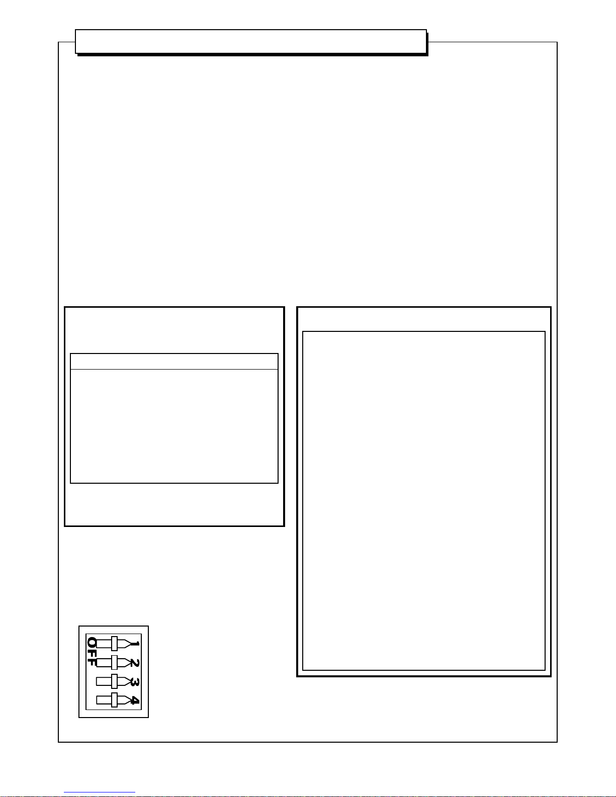
Switch Settings
SHEET 2-9
SW1 settings
software (SW-2393-01) rev D0
Default: switches 1 and 2 OFF
switches 3 and 4 ON
switch(es) state function
1ONraw data
2ONtest mode
34 output baud rate
ON ON 9600, N, 8, 1
ON OFF 4800, N, 8, 1
OFF ON 2400, N, 8, 1
OFF OFF 1200, N, 8, 1
SW2 settings
input baud rate 3 2 1 baud rate
ON ON ON 300
ON ON OFF 600
ON OFF ON 1200
ON OFF OFF 2400
OFF ON ON 4800
OFF ON OFF 9600
OFF OFF ON 19200
OFF OFF OFF 38400
input data bits 5 4 data bits
ON ON 5
ON OFF 6
OFF ON 7
OFF OFF 8
input parity 76 parity
ON ON none
ON OFF even
OFF ON odd
OFF OFF none
switch 8 8function
Xunused
set Vi-POSCON input baud rate to match
Even if a SW2 default is indicated, the printer could be
configured differently than shown. In this case, SW2
settings may need to be determined experimentally.
default settings shown in bold
Page 3

Installing the Epson printer interface
Installing the Epson printer interface
Vi-POSIF-S EPSON TM T 88 serial
SHEET 3-9
power P8
24Vac Pins 1 and 2
12Vdc Pin 3 ground
Pin 4 +12Vdc
check power supply first !
24 VAC or 12 VDC ?
Interface Connection Details
Failure to install the ferrite sleeves on the power and data
cables as shown, will compromise the EMC performance
of this unit, relevant to the EMC directive 89/336/EEC.
ferrite
cable gland on
rear of interface
interface
route data / power cables through their respective
ferrites and loop through once again.
*IMPORTANT: cable must be looped through ferrite sleeve.
ferrite
sleeve
ferrite
sleeve
‘DATA INPUT’
data out P4
Pin 2 ground black
Pin 3 TX data red
data out from P4 should be terminated
with a DB9 as shown below;
Vi-POSCON
DB 9 (F)
DATA IN
Pin 2 Rx Data Red
Pin 5 Ground Black
Page 4

Installing the Epson printer interface
Installing the Epson printer interface
Vi-POSIF-S EPSON TM T 88 serial
SHEET 4-9
Interface Connection Details – RS485
Failure to install the ferrite sleeves on the power and data
cables as shown, will compromise the EMC performance
of this unit, relevant to the EMC directive 89/336/EEC.
RS485 data out P5
Pin 4 - Black
Pin 3 + Red
Pin 2 ground White
Pin 1 -EN
LINK
ferrite
sleeve
ferrite
cable gland on
rear of interface
interface
route data cable through the respective ferrite and loop
through once again.
*IMPORTANT: cable must be looped through ferrite sleeve.
data out from P5 should be terminated with a
DB9 (Vi-POSCON)
Vi-POSCON
DB 9 (F)
DATA IN
Pin 4 RX+ Red
Pin 9 RX- Black
Pin 5 ground White
N.B. towards front of Vi-POSCON unit.
On Vi-POSCON pcb, enable the relevant RS485 input by moving
the corresponding jumper (P9 - P12) per input channel (1-4)
i.e. from ; to ;
Page 5

Installing the Epson printer interface
Installing the Epson printer interface
Vi-POSIF-S EPSON TM T 88 serial
SHEET 5-9
Epson TM T88
(rear view)
Interface Connection Details
(printer end)
cable from interposer
original cable
from processor
ensure that the power cord is
connected and seated correctly
before the printer is repowered !
All logos and names used within this document are properties of their respective companies and are used
here for identification purposes. The afore-mentioned items may also be copyright, trademarks or
registered trademarks of their respective companies and no infringement of those rights is intended.
Cable : 500114
(supplied)
Page 6

Installing the Epson printer interface
Installing the Epson printer interface
Vi-POSIF-S EPSON TM T 88 serial
cable from interposer
original cable
from CPU to printer
Epson TM T88
(rear view)
Interface Connection Details
(printer end)
SHEET 6-9
All logos and names used within this document are properties of their respective companies and are used
here for identification purposes. The afore-mentioned items may also be copyright, trademarks or
registered trademarks of their respective companies and no infringement of those rights is intended.
Cable : 500227
(supplied)
Page 7

Installing the Epson printer interface
Installing the Epson printer interface
Vi-POSIF-S EPSON TM T 88 serial
1. Check advice note.
Check engineering advice note in case the system is to be installed without prior knowledge of store personnel. Only
contact the nominated manager / supervisor in such a situation.
Ensure that the store (check-out supervisor or nominated person) have taken readings from the register before it is
powered down.
2. Identify the EPSON TM-T88 printer.
The EPSON TM-T88 is a modular printer and as such has no fixed position. It is therefore important to identify both the
printer and a suitable location for mounting the printer interfac e .
3. Install the Interposer Cable.
WARNING! - RISK OF ELECTRIC SHOCK.
Ensure power to the printer and terminal is off and the power cord(s) disconnected before connecting the interface.
Remove the printer-to-CPU cable from the RS-232C port at the rear of the printer. Connect the interposer cable supplied
with the interface to this port. Re-connect the printer-to-CPU cable into interposer cable.
Ensure that the locking hardware is secure.
4. Installing the printer interface data cable.
The interface data cable runs from the interposer cable and should be routed along the most direct route available to the
printer interface.
5. Check printer operation.
Before supplying power to the interface connect the pow er co rd(s) back to the p rinter a nd terminal and ensure that p ower
is restored. Check the printer and terminal for normal operation (It may be necessary to contact nominated store
personnel to do this).
6. Power the interface.
As the interface only passively monitors the data line and the units are opto-isolated there should be no degradation in
printer operation once the interface is powered.
If possible, check that valid text is appearing on Laptop/PC and/or Vi-POSCON screen(s).
If the printer displays abnormal operation, check that all connectors are seated properly. If this does not resolve the
problem, return the register to its initial state by removing the interface and contact your FTSS.
SHEET 7-9
original printer-to-
cpu cable
to printer
DB9 to interface
‘DATA INPUT’
I N T E R P O S E R C A B L E
PRINTER PORT
on rear of printer
Page 8

Installing the Epson printer interface
Installing the Epson printer interface
Vi-POSIF-S EPSON TM T 88 serial
SHEET 8-9
All logos and names used within this document are properties of their respective companies and are used
here for identification purposes. The afore-mentioned items may also be copyright, trademarks or
registered trademarks of their respective companies and no infringement of those rights is intended.
cable from interposer
Epson IM-300
(rear view with cover removed)
Interface Connection Details
Cable : 500260
(supplied)
Page 9

Installing the Epson printer interface
Installing the Epson printer interface
Vi-POSIF-S EPSON TM T 88 serial
SHEET 9-9
1. Check advice note.
Check engineering advice note in case the system is to be installed without prior knowledge of store personnel. Only
contact the nominated manager / supervisor in such a situation.
Ensure that the store (check-out supervisor or nominated person) have taken readings from the register before it is
powered down.
2. Identify the EPSON IM-300 terminal.
The EPSON IM-300 has an integrated Epson TM-T88iiR Serial printer. It is therefore important to identify both the
EPOS terminal and a suitable location for mounting the printer interface.
3. Install the Interface Cable.
WARNING! - RISK OF ELECTRIC SHOCK.
Loosen the screw securing the rear cover of the terminal. Remove the rear cover by pulling the upper part of the rear
cover backward then downward.
Identify the COM3 port at the rear of the printer (refer to SHEET 8-9). Connect one 9 way ‘D’ socket end of the interface
cable supplied (500260) to this port. The other 9 way ‘D’ socket end of this cable should be routed along the most direct
route available to the interface.
Ensure that the locking hardware is secure.
Replace the rear cover and fasten the securing screw.
4. Check terminal operation.
Before supplying power to the interface connect the power cord back to the terminal and ensure that power is restored.
Check the terminal for normal operation (It may be necessary to contact nominated store personnel to do this).
5. Power the interface.
As the interface only passively monitors the data line and the units are opto-isolated there should be no degradation in
printer operation once the interface is powered.
If possible, check that valid text is appearing on Laptop/PC and/or Vi-POSCON screen(s).
If the terminal displays abnormal operation, check that all connectors are seated properly. If this does n ot resolve the
problem, return the register to its initial state by removing the interface and contact your FTSS.
 Loading...