

Page 1

RC170 Option
Teach Pendant
Rev.5 EM079P1591F
TP1
Page 2

RC170 Option Teach Pendant TP1 Rev.5
ii
Page 3

RC170 Option
Teach Pendant
UTP1
Rev.5
Copyright © 2006-2007 SEIKO EPSON CORPORATION. All rights reserved.
TP1 Rev.5 i
Page 4

FOREWORD
Thank you for purchasing our robot products.
This manual contains the information necessary for the correct use of the Teach Pendant.
Please carefully read this manual and other related manuals before installing the robot
system.
Keep this manual handy for easy access at all times.
WARRANTY
The robot system and its optional parts are shipped to our customers only after being
subjected to the strictest quality controls, tests, and inspections to certify its compliance
with our high performance standards.
Product malfunctions resulting from normal handling or operation will be repaired free of
charge during the normal warranty period. (Please ask your Regional Sales Office for
warranty period information.)
However, customers will be charged for repairs in the following cases (even if they occur
during the warranty period):
1. Damage or malfunction caused by improper use which is not described in the manual,
2. Malfunctions caused by customers’ unauthorized disassembly.
3. Damage due to improper adjustments or unauthorized repair attempts.
4. Damage caused by natural disasters such as earthquake, flood, etc.
or careless use.
Warnings, Cautions, Usage:
1. If the robot system associated equipment is used outside of the usage conditions and
product specifications described in the manuals, this warranty is void.
2. If you do not follow the WARNINGS and CAUTIONS in this manual, we cannot be
responsible for any malfunction or accident, even if the result is injury or death.
3. We cannot foresee all possible dangers and consequences. Therefore, this manual
cannot warn the user of all possible hazards.
ii TP1 Rev.5
Page 5

TRADEMARKS
Microsoft, Windows, and Windows logo are either registered trademarks or trademarks of
Microsoft Corporation in the United States and/or other countries. Other brand and
product names are trademarks or registered trademarks of the respective holders.
TRADEMARK NOTATION IN THIS MANUAL
Microsoft® Windows® XP Operating system
Microsoft® Windows® Vista Operating system
Throughout this manual, Windows XP, and Windows Vista refer to above respective
operating systems. In some cases, Windows refers generically to Windows XP, and
Windows Vista.
NOTICE
No part of this manual may be copied or reproduced without authorization.
The contents of this manual are subject to change without notice.
Please notify us if you should find any errors in this manual or if you have any comments
regarding its contents.
INQUIRIES
Contact the following service center for robot repairs, inspections or adjustments.
If service center information is not indicated below, please contact the supplier office for
your region.
Please prepare the following items before you contact us.
- Your controller model and its serial number
- Your manipulator model and its serial number
- Software and its version in your robot system
- A description of the problem
SERVICE CENTER
TP1 Rev.5 iii
Page 6

MANUFACTURER & SUPPLIER
TEL : +81-(0)266-61-1802
FAX : +81-(0)266-61-1846
Japan & Others
SEIKO EPSON CORPORATION
Suwa Minami Plant
Factory Automation Systems Dept.
1010 Fujimi, Fujimi-machi,
Suwa-gun, Nagano, 399-0295
JAPAN
SUPPLIERS
Factory Automation/Robotics
TEL : +1-562-290-5900
FAX : +1-562-290-5999
E-MAIL : info@robots.epson.com
Factory Automation Division
TEL : +49-(0)-2159-538-1391
FAX : +49-(0)-2159-538-3170
E-MAIL : robot.infos@epson.de
North & South America
Europe
EPSON AMERICA, INC.
18300 Central Avenue
Carson, CA 90746
USA
EPSON DEUTSCHLAND GmbH
Otto-Hahn-Str.4
D-40670 Meerbusch
Germany
Before Reading This Manual
Following descriptions are indicated throughout the manual by these symbols.
NOTE
)
TIP
)
NOTE
Do not connect the TP1 to following Robot Controllers. Connecting to following Robot
)
NOTE
)
iv TP1 Rev.5
Controllers may result in malfunction of the device since the pin assignments are different.
RC420 / RC520 / SRC5** / SRC-3** / SRC-2**
A coordinate point including the arm pose is defined as “position (point),” and the data is
called “point data.”
The “NOTE” sections describe important information to be
followed for operating the Robot system.
The “TIP” sections describe hints for easier or alternative
operations.
Page 7

TABLE OF CONTENTS
Functions & Installation
1 Safety 3
1.1 Conventions.................................................................................................3
1.2 Safety Precautions ......................................................................................3
1.3 EMERGENCY STOP................................................................................... 7
1.4 Mode Selector Key Switch........................................................................... 8
1.5 Using Teach Pendant in Safeguarded Area ................................................8
2 Specifications 9
2.1 Part Names and Functions ..........................................................................9
2.2 Standard Specifications.............................................................................11
2.3 Outer Dimensions......................................................................................11
3 Installation 12
3.1 Contents .................................................................................................... 12
3.2 Environmental Conditions.......................................................................... 12
3.3 Operating Precautions...............................................................................12
3.4 Connection ................................................................................................13
3.4.1 Typical cable connection............................................................... 13
3.4.2 Connection to the Controller .........................................................14
3.4.3 Operator Panel Connection...........................................................14
3.5 Power Supply ............................................................................................15
3.6 Wall Bracket (Option) ................................................................................16
4 Operation Mode (TEACH/AUTO) 18
4.1 Outline .......................................................................................................18
4.2 Switch Operation Mode ............................................................................. 19
5 Operation Panel (Key Description) 20
6 Enable Switch 23
TP1 Rev.5 v
Page 8

Table of Contents
Operation
1 Teaching Procedure 27
2 TEACH Mode 31
1.1 Jog Operation ........................................................................................... 27
1.2 Teaching ................................................................................................... 28
1.3 Direct Teaching......................................................................................... 29
2.1 [Jog & Teach]............................................................................................ 32
2.1.1 Specifying Point No. ..................................................................... 32
2.1.2 Specifying Jog Mode .................................................................... 32
2.1.3 Specifying Jog Speed................................................................... 33
2.1.4 Executing Step Jog ...................................................................... 33
2.1.5 Executing Continuous Jog............................................................ 33
2.1.6 ON/OFF........................................................................................ 33
2.1.7 Motor ON/OFF.............................................................................. 34
2.1.8 Executing Return to Home ........................................................... 34
2.1.9 Teaching....................................................................................... 34
2.1.10 Saving Point Data to File.............................................................. 35
2.1.11 Loading Point Data from File ........................................................ 35
2.2 Editing Points ............................................................................................ 36
2.2.1 Specifying Point No. ..................................................................... 36
2.2.2 Changing Point Label ................................................................... 36
2.2.3 Changing Coordinate Data and Pose Flag ................................... 36
2.2.4 Deleting Point Data ...................................................................... 36
2.3 Changing Jog Distance Data .................................................................... 37
2.3.1 Changing Distance Data............................................................... 37
2.3.2 Return Data to Defaults................................................................ 37
2.4 Arm/Tool/Local/ECP ................................................................................. 38
2.4.1 Changing Arm No......................................................................... 38
2.4.2 Changing Tool No. ....................................................................... 38
2.4.3 Changing Local No....................................................................... 38
2.4.4 Changing ECP No. ....................................................................... 38
2.5 Executing I/O Commands ......................................................................... 39
2.5.1 Switching Input/Output Status Display ......................................... 39
2.5.2 Output Bit ON/OFF....................................................................... 39
2.6 Executing Motion Commands ................................................................... 40
2.6.1 E2 Series / G Series..................................................................... 40
2.6.2 PS Series ..................................................................................... 40
vi TP1 Rev.5
Page 9

Table of Contents
2.7 Calibrating Origin : E2 Series / G Series ...................................................41
2.7.1 Calibration Procedures (E2 Series)...............................................42
2.7.2 Calibration Procedures (G Series) ................................................50
2.7.3 Setting Righty / Lefty (E2 Series / G Series) ................................. 57
2.8 Calibrating Origin : PS Series.................................................................... 60
2.9 Releasing Brake (PS series only) .............................................................. 66
3 AUTO Mode 68
3.1 Program Command Display.......................................................................70
3.2 I/O Monitor................................................................................................. 71
3.3 Memory I/O Monitor...................................................................................71
3.4 Task Monitor.............................................................................................. 72
3.5 System History ..........................................................................................73
3.6 Program Mode...........................................................................................74
3.6.1 Open Programs.............................................................................75
3.6.2 Building Projects ...........................................................................81
3.6.3 Backing up Projects ...................................................................... 82
3.6.4 Restore Projects ...........................................................................83
3.6.5 Import Files ...................................................................................84
3.6.6 Export Files...................................................................................85
3.6.7 Backup System.............................................................................87
3.6.8 Restore System ............................................................................89
3.6.9 Changing Speed Factor ................................................................91
3.6.10 Configuration.................................................................................91
3.6.11 Change Display Language............................................................93
3.6.12 Update System Software .............................................................. 94
3.7 Backup / Restore ....................................................................................... 96
3.8 Save Controller Statuses........................................................................... 97
3.9 Display Date and Time .............................................................................. 97
3.10 Adjust Brightness and Contrast ................................................................. 98
3.11 Error Messages ......................................................................................... 98
4 Password Setup 99
5 Troubleshooting 100
6 Maintenance Parts List and Option 101
TP1 Rev.5 vii
Page 10

Table of Contents
viii TP1 Rev.5
Page 11

Functions & Installation
This section contains information about functions and
installation of the Teach Pendant to be known before
operation and maintenance.
Page 12

Page 13
1. Safety
1.1 Conventions
Important safety considerations are indicated throughout the manual by the following
symbols. Be sure to read the descriptions shown with each symbol.
WARNING
WARNING
CAUTION
Functions & Installation 1. Safety
This symbol indicates that a danger of possible serious injury
or death exists if the associated instructions are not followed
properly.
This symbol indicates that a danger of possible harm to people
caused by electric shock exists if the associated instructions are
not followed properly.
This symbol indicates that a danger of possible harm to people
or physical damage to equipment and facilities exists if the
associated instructions are not followed properly.
1.2 Safety Precautions
For details of Safety, refer to Safety Chapter in the User’s Guide. Please read and
understand the chapter before using the robot system.
Only trained personnel should design and install the robot system. Trained
personnel are defined as those who have taken robot system training and
maintenance training classes held by the manufacturer, dealer, or local
representative company, or those who understand the manuals thoroughly and
have the same knowledge and skill level as those who have completed the
training courses.
Only authorized personnel who have taken the safety training should be allowed
WARNING
to execute teaching or calibration of the robot system.
The safety training is the program for industrial robot operator that follows the
laws and regulations of each nation. The personnel who have taken the safety
training acquire knowledge of industrial robots (operations, teaching, etc.).
The personnel who have completed the robot system-training class held by the
manufacturer, dealer, or locally-incorporated company are allowed to maintain
the robot system.
TP1 Rev.5 3
Page 14
Functions & Installation 1. Safety
Only authorized personnel who have taken the safety training should be allowed
to maintain the robot system.
The safety training is the program for industrial robot operator that follows the
laws and regulations of each nation. The personnel who have taken the safety
training acquire knowledge of industrial robots (operations, teaching, etc.),
knowledge of inspections, and knowledge of related rules/regulations. The
personnel who have completed the robot system-training and
maintenance-training classes held by the manufacturer, dealer, or locally
incorporated company are allowed to maintain the robot system.
Immediately press the EMERGENCY STOP switch whenever you suspect any
danger.
The Teach Pendant is equipped with an EMERGENCY STOP switch. Before
operating the Teach Pendant, make sure that the EMERGENCY STOP switch
on the Teach Pendant functions properly. Operating the Teach Pendant when
the switch does not function properly is extremely hazardous and may result in
serious bodily injury and/or serious damage to the equipment, as the switch
WARNING
cannot fulfill its intended function in an emergency.
When nothing appears on its display window, the Teach Pendant is not
connected with the Controller. In this case, the EMERGENCY STOP switch on
the Teach Pendant will not function.
WARNING
If the Teach Pendant is not connected to the controller, DO NOT place it within
easy reach during operation. You might press the EMERGENCY STOP switch
on the unconnected Teach Pendant by mistake to stop the robot system in an
emergency. Pressing the EMERGENCY STOP switch on the disconnected
Teach Pendant in an emergency is extremely hazardous and may cause
serious safety problems.
When entering the safeguarded area for teaching, change the mode of the
Teach Pendant to TEACH and take out the key for the mode selector key switch
and then enter the safeguarded area with the key. Leaving the key in the
mode selector key switch is extremely hazardous and may cause serious safety
problems as someone else may inadvertently change the mode to the automatic
operation.
Be sure to connect the cables between the Controller and the Teach Pendant
properly. Do not allow unnecessary strain on the cables. (Do not put heavy
objects on the cables. Do not bend or pull the cables forcibly.) The
unnecessary strain on the cables may result in damage to the cables,
disconnection, and/or contact failure. Damaged cables, disconnection, or
contact failure is extremely hazardous and may result in electric shock and/or
improper function of the system. Do not use the cables near heat or fire.
4 TP1 Rev.5
Page 15

CAUTION
Functions & Installation 1. Safety
Do not shock the Teach Pendant physically or place any object on Teach
Pendant. A liquid crystal display is used for the Teach Pendant display. If
the display is damaged, liquid crystal may leak out. Liquid crystal is harmful.
If it sticks on your skin or clothes, immediately wash your skin and clothes
thoroughly with clean water and soap immediately.
The Teach Pendant must be used within the environmental conditions
described in this manual. This product has been designed and manufactured
strictly for use in a normal indoor environment. Using this product in the
environment that exceeds the conditions may not only shorten the life cycle of
the product but also cause serious safety problems.
Do not disassemble, repair, or modify the Teach Pendant by yourself.
Improper disassembly, repair, or modification of the Teach Pendant may cause
not only improper function of the robot system but also serious safety problems.
Safety-related Requirements
Specific tolerances and operating conditions for safety are contained in the manuals for
the robot, controller and other devices. Be sure to read those manuals as well.
Robot systems safety standard and other examples are given in this chapter. Therefore,
to ensure that safety measures are complete, please refer to the other standards listed as
well.
(Note: The following is only a partial list of the necessary safety standards.)
EN 61000-6-2
Electromagnetic compatibility (EMC). Generic standards.
Immunity standard for industrial environments
EN 61000-6-4
Electromagnetic compatibility (EMC). Generic standards.
Emission standard for industrial environments
IEC 61131-2
Programmable controllers - Part 2: Equipment requirements
and tests
EN ISO 12100-1
Safety of machinery - Basic concepts, general principles for
design -- Part 1: Basic terminology, methodology
EN ISO 12100-2
Safety of machinery - Basic concepts, general principles for
design -- Part 2: Technical principles
EN 418
Safety of machinery - Emergency stop equipment, functional
aspects - principles for design
EN 614-1
Safety of machinery - Ergonomic design principles; part 1:
terminology and general principles
EN 894-1
Safety of machinery - Ergonomics requirements for the
design of displays and control actuators; Part 1: General
principles for human interactions with displays and control
actuators
EN 894-2
Safety of machinery - Ergonomics requirements for the
design of displays and control actuators; Part 2: Displays
TP1 Rev.5 5
Page 16

Functions & Installation 1. Safety
EN 894-3
Safety of machinery - Ergonomics requirements for the
design of displays and control actuators - Part 3: Control
actuators
EN 954-1
(ISO 13849-1)
EN 60204-1
UL 508
(=CSA C22.2 No.14)
EN 50178
EN 61131-1 (IEC1131-1)
EN 61131-2 (IEC1131-2)
UL 1740
ANSI/RIA R15.06,
(=CSA-Z434-94)
ISO 11161
EN 12417
EN 14070
Safety of machinery - Safety-related parts of control systems
-- Part 1: General principles for design
Safety of machinery. Electrical equipment of machines.
General requirements
Industrial Control Panels
Electronic equipment for use in power installations
Programmable controllers - Part 1: General information
Programmable controllers; part 2: equipment requirements
and tests
Industrial robots and robotic equipment
American National Standard; Industrial Robots and Robot
Systems - Safety Requirements
Industrial automation systems - Safety of integrated
manufacturing systems - Basic requirements
Machine tools. Safety. Machining centers
Safety of machine tools - Transfer and special-purpose
machines.
6 TP1 Rev.5
Page 17

1.3 EMERGENCY STOP
Immediately press the EMERGENCY STOP switch whenever you suspect any danger.
The Teach Pendant is equipped with an EMERGENCY STOP switch. Before
operating the Teach Pendant, make sure that the EMERGENCY STOP switch on the
Teach Pendant functions properly. Operating the Teach Pendant when the switch
does not function properly is extremely hazardous and may result in serious bodily
WARNING
injury and/or serious damage to the equipment, as the switch cannot fulfill its intended
function in an emergency.
When nothing appears on its display window, the Teach Pendant is not connected with
the Controller. In this case, the EMERGENCY STOP switch on the Teach Pendant
will not function.
When the EMERGENCY STOP switch is pushed, stops the programs execution and halts
the robot excitation. Programs and point data will not be damaged.
When pushed, the EMERGENCY STOP switch mechanically holds that state and
electrically holds the emergency stop state.
Functions & Installation 1. Safety
Reset EMERGENCY STOP
Follow these steps to reset Emergency Stop condition.
(1) Remove the cause of the Emergency Stop and verify that it is safe to operate the robot
again.
(2) Release the EMERGENCY STOP switch. To release the mechanical latch, turn the
EMERGENCY STOP switch to the right.
(3) Turn the Teach Pendant mode selector key switch to “Teach”.
(4) Press the <Reset> key on the operation
E-STOP Lamp
panel to reset the Emergency Stop.
(5) Make sure that the E-STOP lamp on the
operation panel is OFF.
<Reset> Key
TP1 Rev.5 7
Page 18

Functions & Installation 1. Safety
1.4 Mode Selector Key Switch
The mode selector key switch is used to select TEACH or AUTO operation mode. For
safety, if the mode is changed during program execution, all tasks will be stopped.
Mode switching during task execution
AUTO → TEACH
(1) Press the <Stop> button to stop all tasks normally.
(2) Turn the mode selector key switch to “Teach”.
TEACH → AUTO
Turn the mode selector key switch to “Auto” and close the latch release input.
1.5 Using Teach Pendant in Safeguarded Area
When the mode selector switch of the Teach Pendant is switched to “Teach” mode, the
operator can jog and move the robot to predefined points in slow speed when the enable
switch is gripped and the safeguard is open.
Personnel that will be using the Teach Pendant should be thoroughly trained on how to
use it.
Follow these guidelines when using the Teach Pendant in the safeguarded area:
(1) Before entering the safeguarded area to use the Teach Pendant, turn the mode selector
key switch to “Teach”.
(2) Enter the safeguarded area and perform the teaching operations.
(3) Leave the safeguarded area and close the safeguard.
(4) Return the mode selector key switch to “Auto”.
(5) Close the latch release input. (For details on the pin assignments of the
EMERGENCY connector, refer to Setup & Operation 9.3 Pin Assignments in the
RC170 controller manual.)
8 TP1 Rev.5
Page 19
2. Specifications
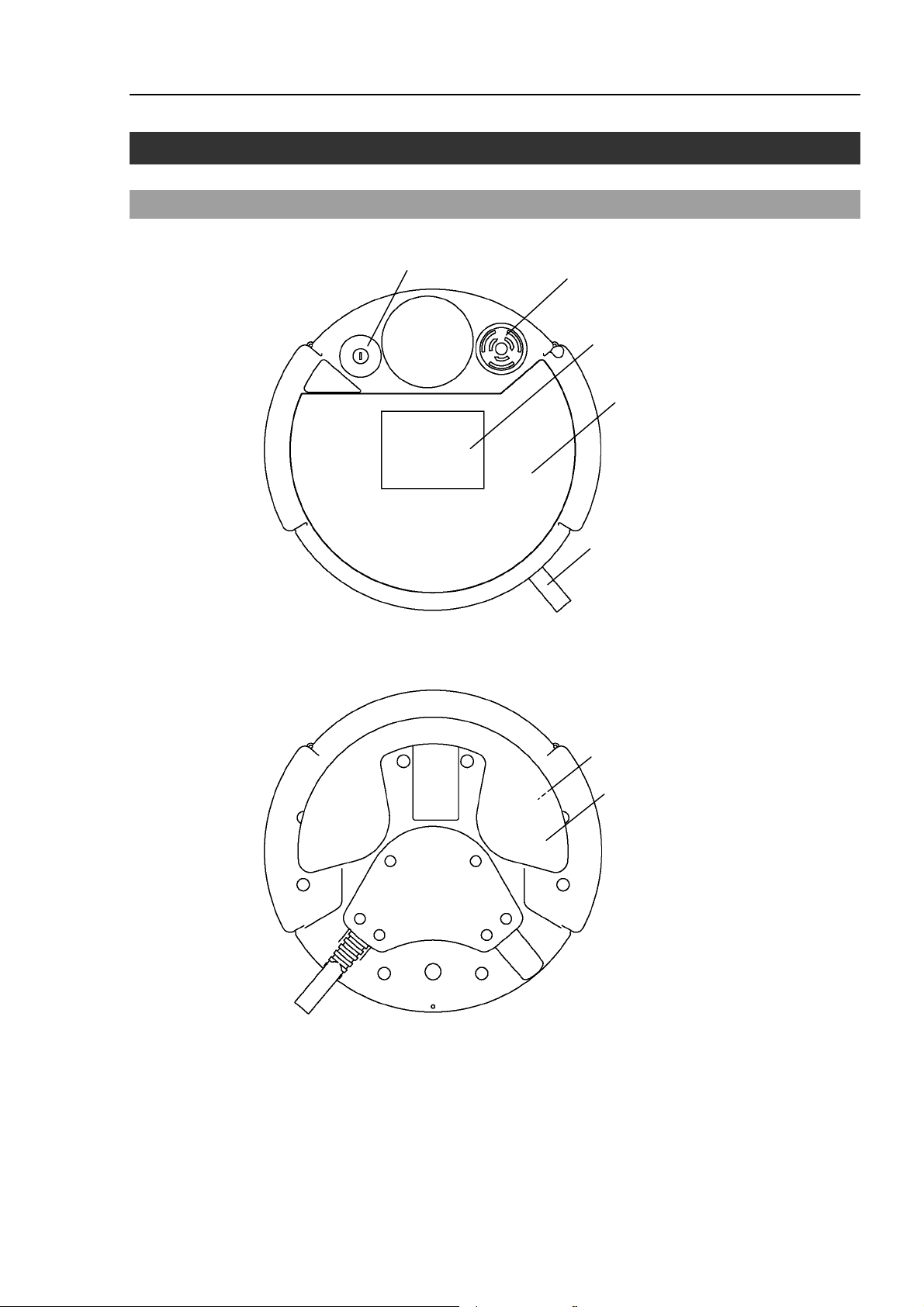
2.1 Part Names and Functions
Front view
(1)
Functions & Installation 2. Specifications
(2)
(3)
(4)
Back view
(5)
(6)
(7)
TP1 Rev.5 9
Page 20

Functions & Installation 2. Specifications
(1) Mode Selector Key switch
The mode selector key switch is used to change the operation mode between TEACH
and AUTO. The mode can be fixed by pulling out the key. When the mode is
switched while a program is executing, the program will be stopped.
Close the latch when switching the mode from TEACH to AUTO.
For the procedure to switch the mode, refer to Setup & Operation 1.4 Mode Selector
Key Switch.
(2) EMERGENCY STOP switch
When this switch is pushed, the Emergency Stop state is held both mechanically and
electrically. Pushing the switch stops the program, removes power to robot motors and
stops the manipulator motion immediately.
To cancel the Emergency Stop state, first turn the EMERGENCY STOP switch to the
right to release the mechanical latch. Switch the mode selector key switch to “Teach”.
Press the <Reset> key to reset the electrically held Emergency Stop state. The
E-STOP lamp goes OFF.
For the procedure to reset the EMERGENCY STOP switch, refer to Setup & Operation
1.3 EMERGENCY STOP.
(3) Display
Displays various kinds of information.
(4) Operation Panel
Teaching operation, automatic operation and data input are available.
(5) Connection Cable
This is a cable to connect the Teach Pendant and the Controller.
The connector is attached at the end of the cable.
(6) Enable switch
This is a three-position switch. Motion and I/O output commands are available while
the switch is gripped when the Teach Pendant is operated in TEACH mode. The
switch turns ON when it is at the midpoint, and it turns OFF when it is fully gripped or
released.
(7) Handle
Use this part as the hand strap while operating the Teach Pendant.
10 TP1 Rev.5
Page 21
2.2 Standard Specifications
Item Specification
Functions & Installation 2. Specifications
Rated voltage
General
specifications
Display
specifications
Serial interface
specifications
Electric power consumption
Weight
Display element
Contrast
Back light
Electrical characteristics
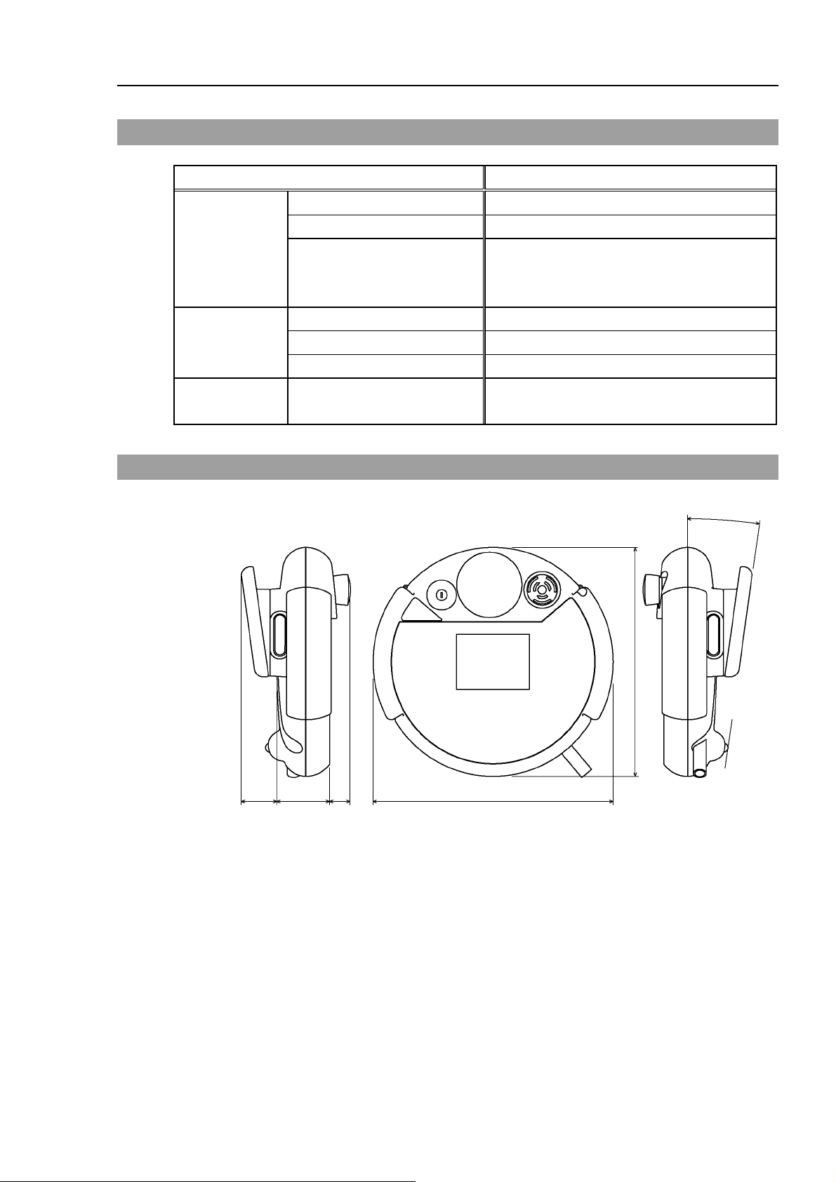
2.3 Outer Dimensions
DC24 V
6 W or less
1075 g
(include EMERGANCY STOP switch and the
mode selector key switch, excluding cables)
F-STN type Black and white LCD
8-level (Gray scale)
LED (Color : White)
Compliant with RS-422A standard
°
8
240
37
NOTE
Use the installation metal in the attachment when attaching the Teach Pendant to a panel,
or the like.
55 22 251.9
(Unit : mm)
TP1 Rev.5 11
Page 22

Functions & Installation 3. Installation
3. Installation
3.1 Contents
TP1 (with cables) : 1 unit
Mode selector key : 2 units
3.2 Environmental Conditions
The Teach Pendant must be used in an environment that conforms to the following
requirements to ensure safe and reliable operation.
Item Condition
Ambient temperature
Ambient relative
temperature
Protection structure
Environment
- Keep away from dust, oily smoke, salinity, metal powder
0 to 50 deg C (with minimal variation)
5 to 95%
IP65 (excluding the connector)
- Keep away from flammable or corrosive solvents and
and other contaminants.
gases.
3.3 Operating Precautions
CAUTION
Do not drop the Teach Pendant or hit hard against other objects to avoid
damage, as the case of the Teach Pendant may be damaged since the main
body is made of resin.
Use the hand strap to prevent dropping the Teach Pendant during operation.
Do not hit the touch panel of the Teach Pendant against a hard object or put
excessive pressure on it. The touch panel is made of glass. Therefore, if
excessive pressure is put on it, it may be damaged.
Do not press or rub the surface of the front panel push buttons with a hard
object such as a tool. The surface of the buttons may be damaged as they are
easily scratched.
Wipe the dirt and oils adhering to the surface of the Teach Pendant display with
a soft cloth dampened with a neutral detergent or an alcohol solvent.
If using the mounting bracket, check that the bracket and screws are not bent or
loosened.
12 TP1 Rev.5
Page 23
A
3.4 Connection
This section indicates the connection of the Controller and the Teach Pendant.
Be sure to connect the cables of Controller and Teach Pendant properly. Do
not allow unnecessary strain on the cables. (Do not put heavy objects on the
cables. Do not bend or pull the cables forcibly.) The unnecessary strain on the
cables may result in damage to the cables, disconnection, and/or contact failure.
Damaged cables, disconnection, or contact failure is extremely hazardous and
may result in improper function of the system.
Make sure that the pins are not bent when connecting the connector.
CAUTION
Connecting the connector with the pin bent may cause malfunction and result in
improper function of the system.
The connector connected to the end of the cable is a general-purpose type
connector. When connecting the connector, note that the waterproof efficiency
and dustproof efficiency of the connector do not comply with IP65.
Functions & Installation 3. Installation
NOTE
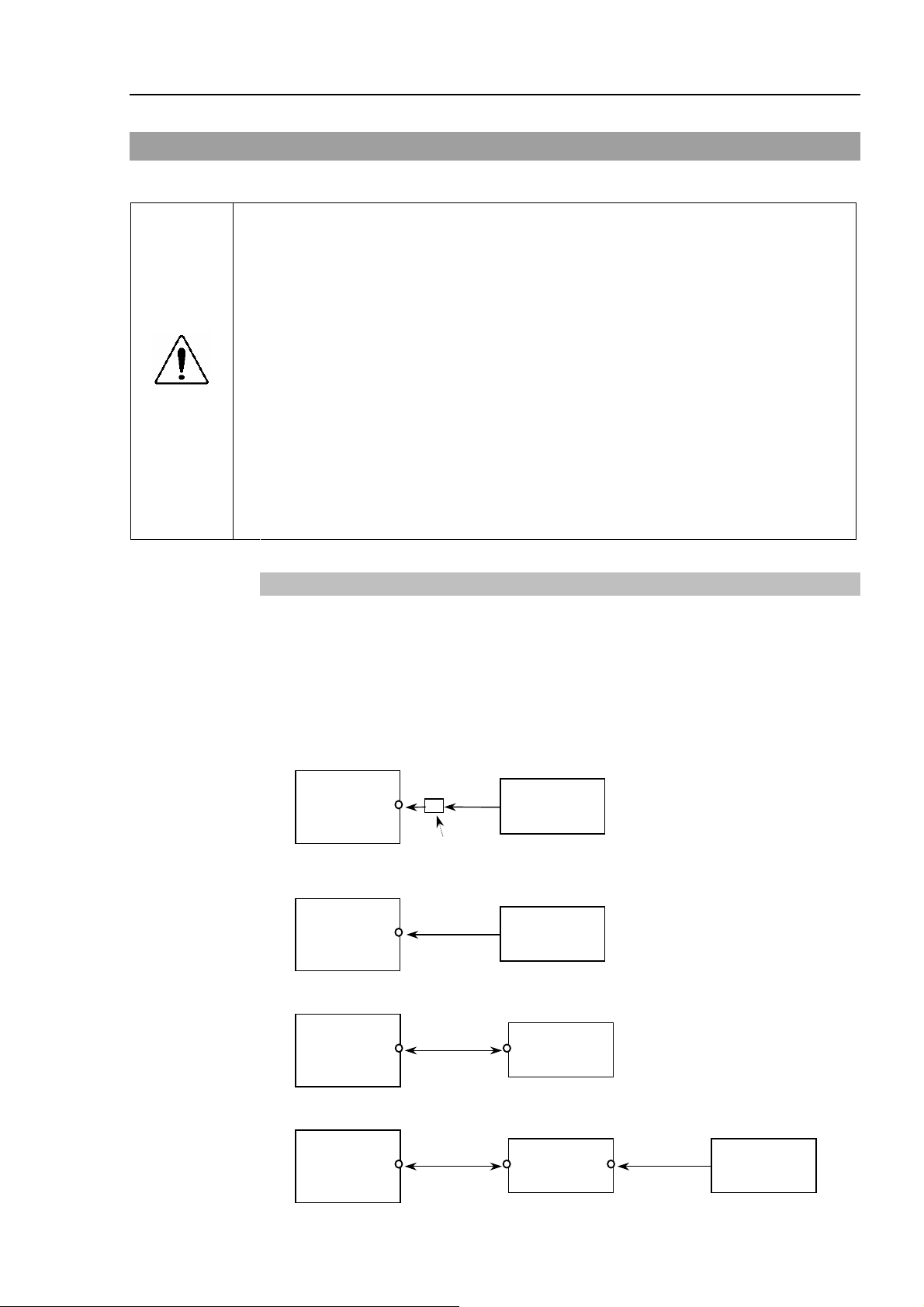
3.4.1 Typical cable connection
The Teach Pendant and the Operator Panel is connected to TP/OP port of controller.
When nothing is connected to the TP/OP port, Emergency Stop status occurs to the
Controller. When the Teach Pendant or the Operator Panel is not connected, connect the
TP/OP bypass plug.
Example
A: Only using Teach Pendant (TP Cable A)
Controller
B: Only using Teach Pendant (TP Cable B)
Controller
C: Only using Operator Panel
TP Cable
A
Conversion Kit CK1
TP Cable
B
Teach
Pendant
Teach
Pendant
Controller
OP Cable
Operator
Panel
D: Using Teach Pendant and Operator Panel
Controller
OP Cable TP Cable
Operator
Panel
Teach
Pendant
TP1 Rev.5 13
Page 24

Functions & Installation 3. Installation
NOTE
The shape of the cable connector used in connection A and D differs to connection B.
NOTE
NOTE
TP Cable A : Circular connector to connect to the Operator Panel.
(Direct connection is available with conversion kit CK1.)
TP Cable B : D-sub connector to connect directly to the Controller.
When Teach Pendant with Operator Panel cable is inserted to the TP port of the
Operator Panel, both Operator Panel and Teach Pendant are available.
(Connection D)
Do not connect TP1 to the following Robot Controllers. Connecting to the
following Robot Controllers may result in malfunction of the device since the pin
assignments are different.
RC420 / RC520 / SRC5** / SRC-3** / SRC-2**
3.4.2 Connection to the Controller
(1) Make sure that the Controller and the Robot is connected properly.
(2) Connect the connector of the Teach Pendant cable to the TP/OP port of Controller.
(3) Turn ON the controller.
NOTE
NOTE
NOTE
Teach Pendant insert and removal from the Controller are available when the
Controller power is ON.
When Teach Pendant connector is removed from the Controller with the mode
selector key switch of Teach Pendant that is in “Teach” position, the operation mode
will remain in TEACH mode. The operation mode cannot be switched to AUTO
mode. Make sure to remove the Teach Pendant after switching the operation mode
to “Auto” mode.
3.4.3 Operator Panel Connection
(1) Make sure that the Controller and the Robot is connected properly.
(2) Connect the connector of the Operator Panel to the TP/OP port of Controller.
(3) Turn ON the Controller.
(4) Connect the connector of Teach Pendant to the Operator Panel.
Teach Pendant insert and removal from the Controller are available when the
Controller power is ON.
Make sure that the Controller is turned OFF when inserting or removing the Operator
Panel.
NOTE
14 TP1 Rev.5
When Teach Pendant connector is removed from the Controller with the mode
selector key switch of Teach Pendant that is in “Teach” position, the operation mode
will remain in TEACH mode. The operation mode cannot be switched to AUTO
mode. Make sure to remove the Teach Pendant after switching the operation mode
to “Auto” mode.
Page 25
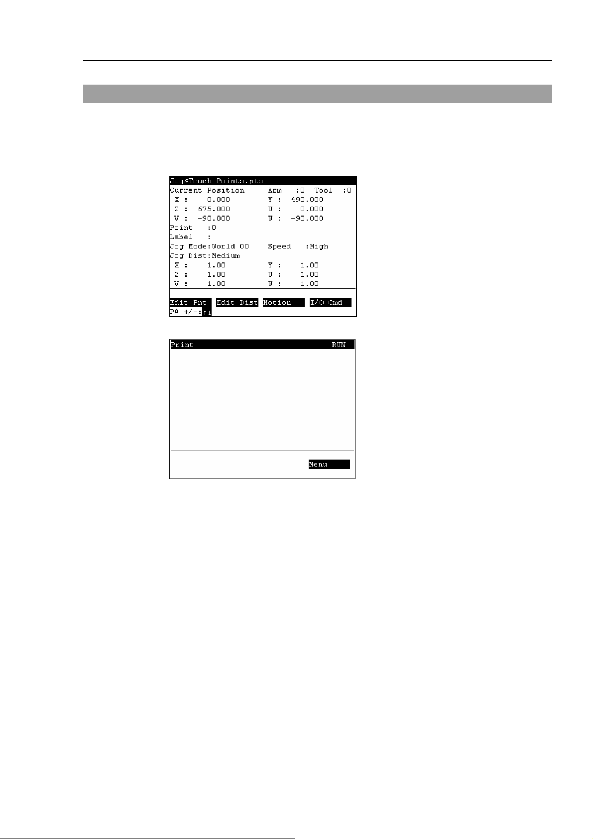
3.5 Power Supply
The power of the Teach Pendant is supplied via the TP/OP connector on the Controller.
After the completing the Controller and the Teach Pendant communication, the following
screen will appear on the display of the Teach Pendant.
TEACH mode
AUTO mode
Functions & Installation 3. Installation
TP1 Rev.5 15
Page 26
Functions & Installation 3. Installation
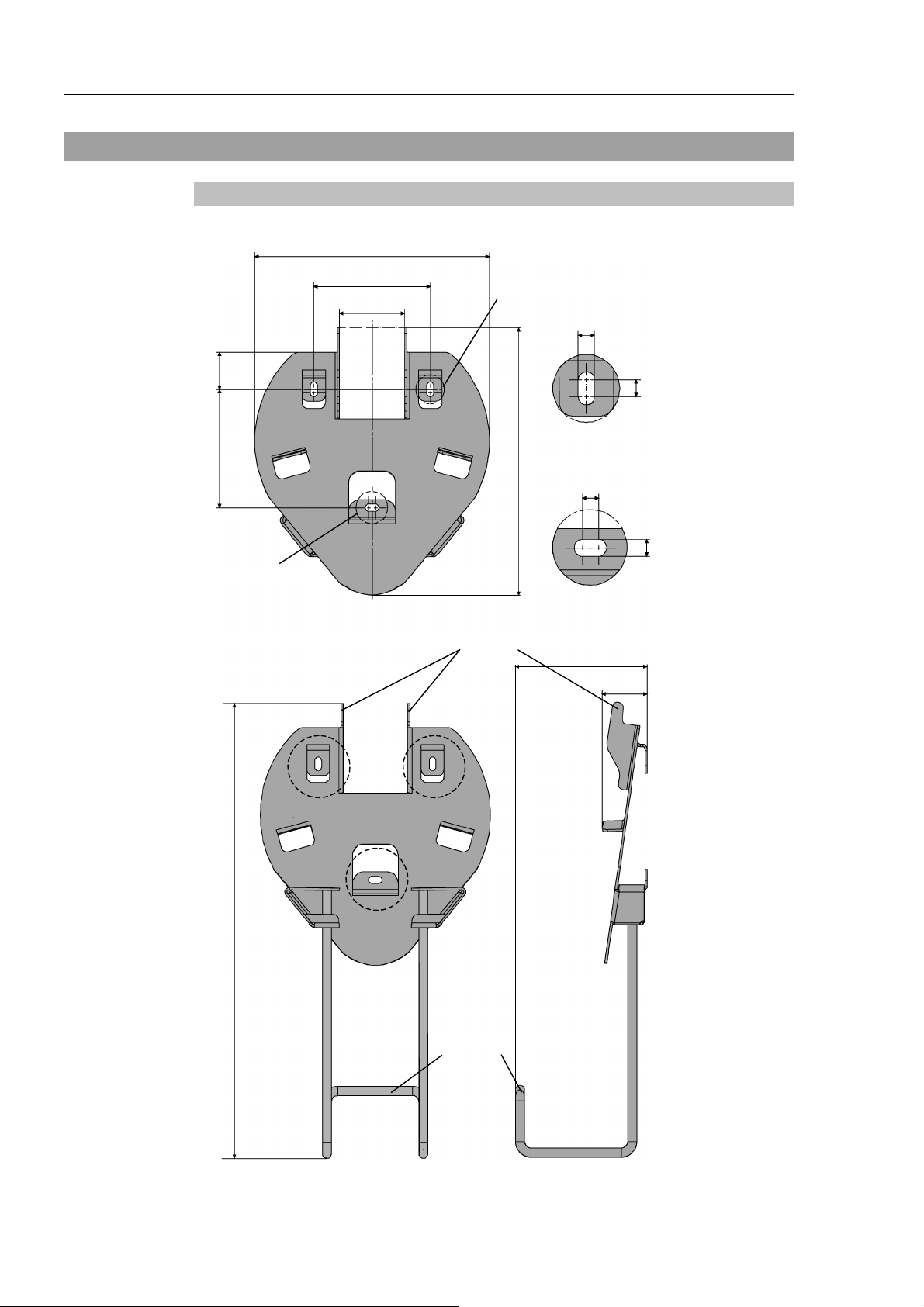
3.6 Wall Bracket (Option)
Outer Dimension
31.4
100
[Unit :mm]
201.4
100
56.2
J
6
6
Detail : J
226
6
6
K
Front View
Hook A
Detail : K
118
392.9
39.6
Hook B
Back View Side View
16 TP1 Rev.5
Page 27
Functions & Installation 3. Installation
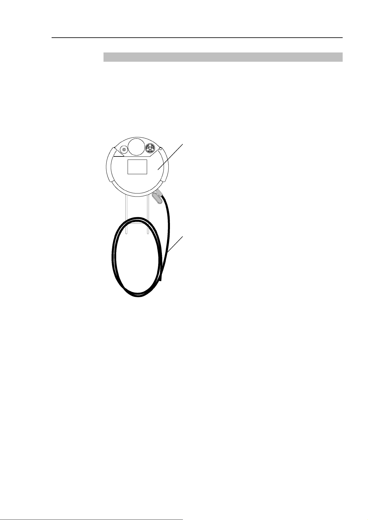
Mount and Use
Mount the Teach Pendant with the wall bracket in the following procedures.
(1) Secure the wall bracket to the wall with three screws (positions are indicated by
dotted line in the Outer Dimension).
(2) Hang the handle of the Teach Pendant to Hook A.
(3) Hang the cable of the Teach Pendant to Hook B.
Teach Pendant
Cable
TP1 Rev.5 17
Page 28
Functions & Installation 4. Operation Mode (TEACH/AUTO)
4. Operation Mode (TEACH/AUTO)
NOTE
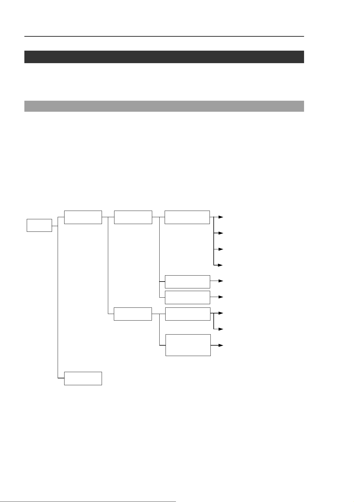
4.1 Outline
RC170
TEACH mode Teaching Jog & Teach
A coordinate point including the arm pose is defined as “position (point),” and the data is
called “point data.”
Robot system has two operation modes TEACH mode and AUTO mode.
TEACH mode
This mode enables point data teaching and check close from the
Robot using the Teach Pendant.
Robot operates in Low power status.
AUTO mode
This mode enables automatic operation (program execution) of the
Robot system at the manufacture operation, besides, programming,
debug, adjustment, and maintenance of the Robot system.
This mode cannot operate Robots or run program with the Safety
Door open.
2.1 Jog & Teach
2.3 Changing
the Jog Distance data
2.4 Arm / Tool / Local / ECP
AUTO mode
Maintenance
Point Editor
Motion Command
Calibration
Brake Release
(Six-axis)
2.5 Executing I/O Commands
2.2 Editing Points
2.6 Executing Motion Commands
2.7 Calibration
(E2 series / G series)
2.8 Calibration
(PS series)
2.9 Releasing the Brake
(PS3 only)
18 TP1 Rev.5
Page 29

Functions & Installation 4. Operation Mode (TEACH/AUTO)
4.2 Switch Operation Mode
Change the TEACH mode and AUTO mode with the mode selector key switch on the
Teach Pendant.
TEACH mode
AUTO mode
Turn the mode selector key switch to “Teach” for TEACH mode.
Pauses the executing program when operation mode is switched to
TEACH mode.
The operating Robot stops by Quick Pause.
Turn the mode selector key switch to “Auto” and change the latch
release input signal to ON position for AUTO mode.
TP1 Rev.5 19
Page 30
Functions & Installation 5. Operation Panel (Key Description)
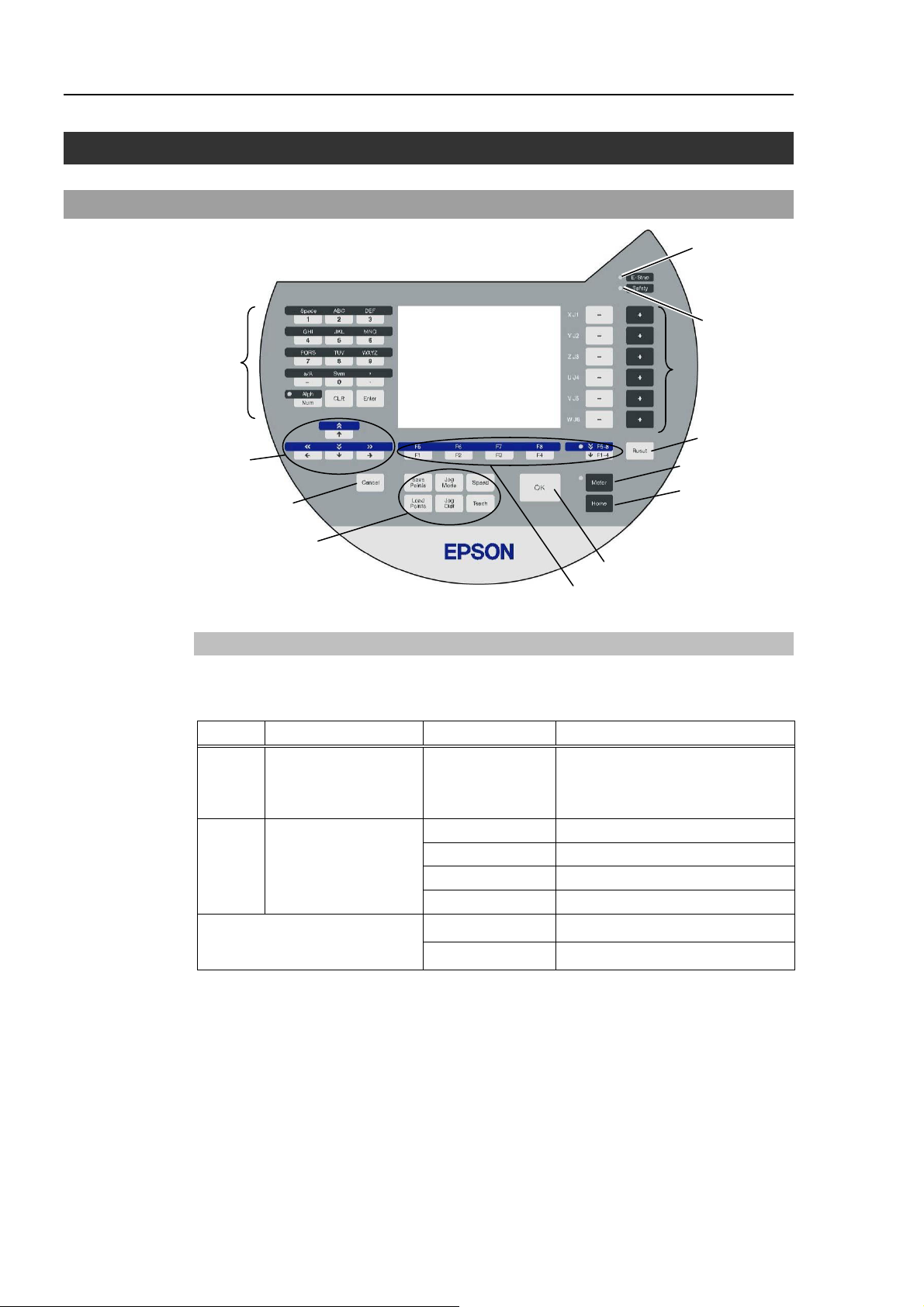
5. Operation Panel (Key Description)
Key Description
Alphabet and Number
Input keys
Arrow keys
Cancel key
Teaching keys
Alphabet and Number Input Keys
Input mode alphabet/number switches by turning ON/OFF the “Alph” lamp.
Press the <Alph/Num> key to turn ON/OFF the “Alph” lamp.
OK key
Function keys
E-STOP lamp
Safety lamp
Jog keys
Reset key
Motor key
Home key
Alph Mode Key Function
OFF Number input mode
From 0 to 9
- (minus)
Number input
.(period)
ABC to WXYZ Alphabet input
ON Alphabet input mode
SP (space) Space input
a/A Case selector
Sym Symbol input
CLR Clear number and alphabet
Common
Enter Set number and alphabet
20 TP1 Rev.5
Page 31

Functions & Installation 5. Operation Panel (Key Description)
Arrow Keys
Mode switches by turning ON/OFF the “F5-8” lamp.
Press the <F1-4 / F5-8> key to turn ON/OFF the “F5-8” lamp.
F5-8 Mode Key Function
+1 the value
↑
Move the cursor up
OFF Normal mode
ON Scroll mode
−1 the value
↓
Move the cursor down
Move the cursor to the left
←
Move the cursor to the right
→
<<
+10 the value
Move to previous page
>>
−10 the value
Move to next page
<< High speed cursor motion to the left
>> High speed cursor motion to the right
NOTE
Function Keys
Press the <F5-8> key to turn ON/OFF the “F5-8” lamp. The display changes.
Example : Jog&Teach Screen
<F1> <F2> <F3> <F4>
<F5> <F6> <F7> <F8>
Example : Press the <F3> key to display the Motion screen.
When a function key is not assigned to a screen, the key is invalid. Example : <F7>
“F5-8” OFF
“F5-8” ON
TP1 Rev.5 21
Page 32

Functions & Installation 5. Operation Panel (Key Description)
Jog Keys
Jog key is available only in TEACH mode.
Key Function
−
Move the target joint (X to W, J1 to J6) to − direction
+ Move the target joint (X to W, J1 to J6) to + direction
Teaching Keys
Teaching key is available only in TEACH mode.
Key Function
Save Points Save the point data to a file
Load Points Read the point data from a file
Jog Mode Specify the Jog mode
Jog Dist Specify the Jog distance
Speed Specify the Jog speed
Teach Save the current position data
Other keys
Key Function
Cancel Cancel the setting and go back to the previous screen
OK Save the setting and move on to the next screen
Reset Set the initial setup status
Motor* Switch the motor power ON/OFF
Home* Move the robot to home position
* Keys with this mark are available only in TEACH mode.
Lamp
Lamp Function
E-Stop Turns ON when the EMERGENCY STOP switch is pressed
Safety Turns ON when the safeguard is open
22 TP1 Rev.5
Page 33

6. Enable Switch
In TEACH mode, several operations require use of the 3-position enable switch located on
the left rear of the pendant. The enable switch can be operated either hand.
When the enable switch is required to execute an operation, you must grip the switch to
the center (enable) position. To do this, pull the switch with the left hand fingers until it
just stops at the center detent. If you pull harder, or let go, then the switch will be
disengaged and the operation will be canceled.
Enable Switch (for Left Hand)
Functions & Installation 6. Enable Switch
Enable Switch (for Right Hand)
Back view Left side viewRight side view
How to press the Enable switch
Grip the enable switch by the finger on the hand holding the handler.
Example
: When gripping by the left hand
Handle
TP1 Rev.5 23
Page 34

Functions & Installation 6. Enable Switch
24 TP1 Rev.5
Page 35

Operation
This section contains information about operation of the
Teach Pendant and maintenance procedure.
27
Page 36

Page 37

1. Teaching Procedure
The basic jog operation and teaching procedure is indicated.
Switch the mode selector switch to “Teach” to display the following screen.
NOTE
)
A coordinate point including the arm pose is defined as “position (point),” and the data is
called “point data.”
Operation 1. Teaching Procedure
1.1 Jog Operation
Move the Robot to the teaching position by one of the following operation (Step Jog
operation, Continuous Jog operation).
Step Jog Operation
In Step Jog, moves the Robot by pressing the Jog key each time.
Jog distance of the Robot is configured before hand.
Press the <Jog Dist> key to specify the [Jog Dist] (Long, Medium, Short).
Execute the step jog by gripping the enable switch as pressing the Jog key.
Continuous Jog Operation
In Continuous Jog, moves the Robot while pressing the Jog key.
Press the <Jog Dist> key to select “Cont Jog” for the [Jog Dist].
Execute the continuous jog by gripping the enable switch as pressing the Jog key.
TP1 Rev.5 27
Page 38

Operation 1. Teaching Procedure
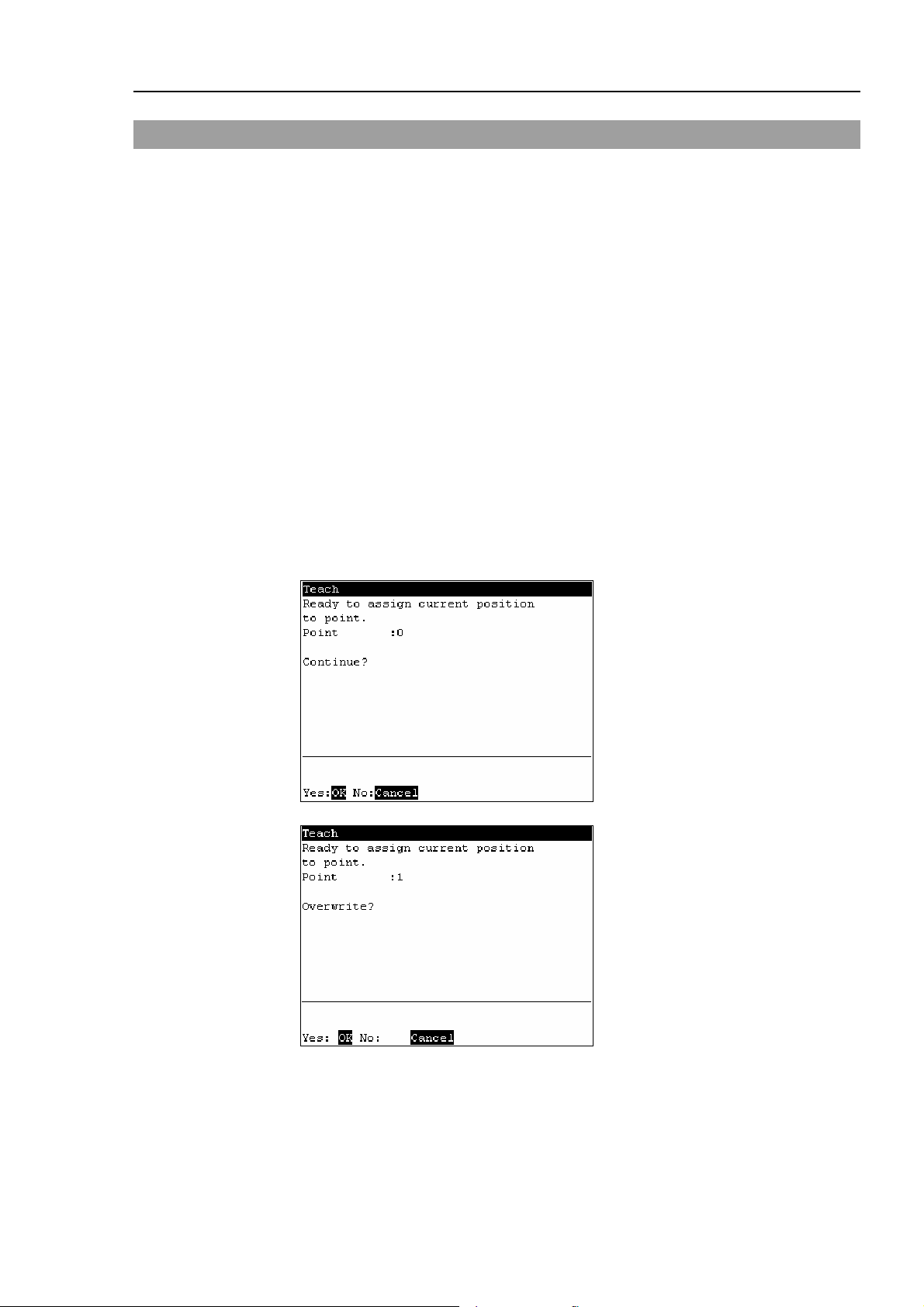
1.2 Teaching
Apply the Robot position to the specified point number.
(1) Specify the point number by changing the value in the [Point] using the <↑> and
<↓> keys.
[Label] display changes by changing the point number.
(2) Press the <Teach> key.
(3) The following screen appears.
When the point number is already used, the following screen appears.
(4) Press the <OK> key to assign the robot position.
(5) Press the <Save Points> key to display the following screen.
Enter the file name and press the <Enter> key.
(6) Press the <OK> key to save the file.
28 TP1 Rev.5
Page 39
1.3 Direct Teaching
“Direct teach” is a way to teach the Robot directly by setting the teaching joint to
servo-OFF.
Apply the Robot position to the specified point number.
(1) Specify the point number by changing the value in the [Point] using the <↑> and
<↓> keys.
[Label] display changes by changing the point number.
(2) Press the <Jog Dist> key to select “Free Joint” for the [Jog Dist].
Set each joint to servo ON or OFF.
<+> key : Lock : Servo OFF the joint
<−> key : Free : Servo ON the joint
<F2> key : All Lock : Servo OFF all the joint
<F3> key : All Free : Servo ON all the joint
(3) Servo OFF joint can be moved with hands.
Move the Robot arm to the position to teach.
Operation 1. Teaching Procedure
(4) Press the <Teach> key.
(5) The following screen appears.
When the point number is already used, the following screen appears.
(6) Press the <OK> key to assign the robot position.
TP1 Rev.5 29
Page 40

Operation 1. Teaching Procedure
(7) Press the <Save Points> key to display the following screen.
Enter the file name and press the <Enter> key.
(8) Press the <OK> key to save the file.
30 TP1 Rev.5
Page 41

2. TEACH Mode
Switch the mode selector key switch to “Teach” to enter the TEACH mode. In this mode,
jog, teaching, operation commands, I/O commands, and other operations and commands
can be executed using the Teach Pendant.
Note, however, that the program cluster cannot be executed.
Jog&Teach
F1
F2
F5
2.1 Jog & Teach
F6
Point Editor
Edit Distance
Arm/Tool/Local/ECP
Operation 2. TEACH Mode
2.2 Editing Points
2.3 Changing the Jog Distance Data
2.4 Arm / Tool / Local / ECP
F4
F3
F8
NOTE
)
I/O Command
Motion Command
Maintenance
A coordinate point including the arm pose is defined as “position (point),” and the data is
Calibration
Brake
2.5 Executing I/O Commands
2.6 Executing Move Commands
2.7 Calibrating (E2 series / G series)
2.8 Calibrating (PS series)
2.9 Releasing the Brake (PS3 only)
Jog&Teach F1………………
…………………….......
…………………….......
Screen nam e
Function key
Reference page
Teaching
Maintenance
called “point data.”
TP1 Rev.5 31
Page 42
Operation 2. TEACH Mode
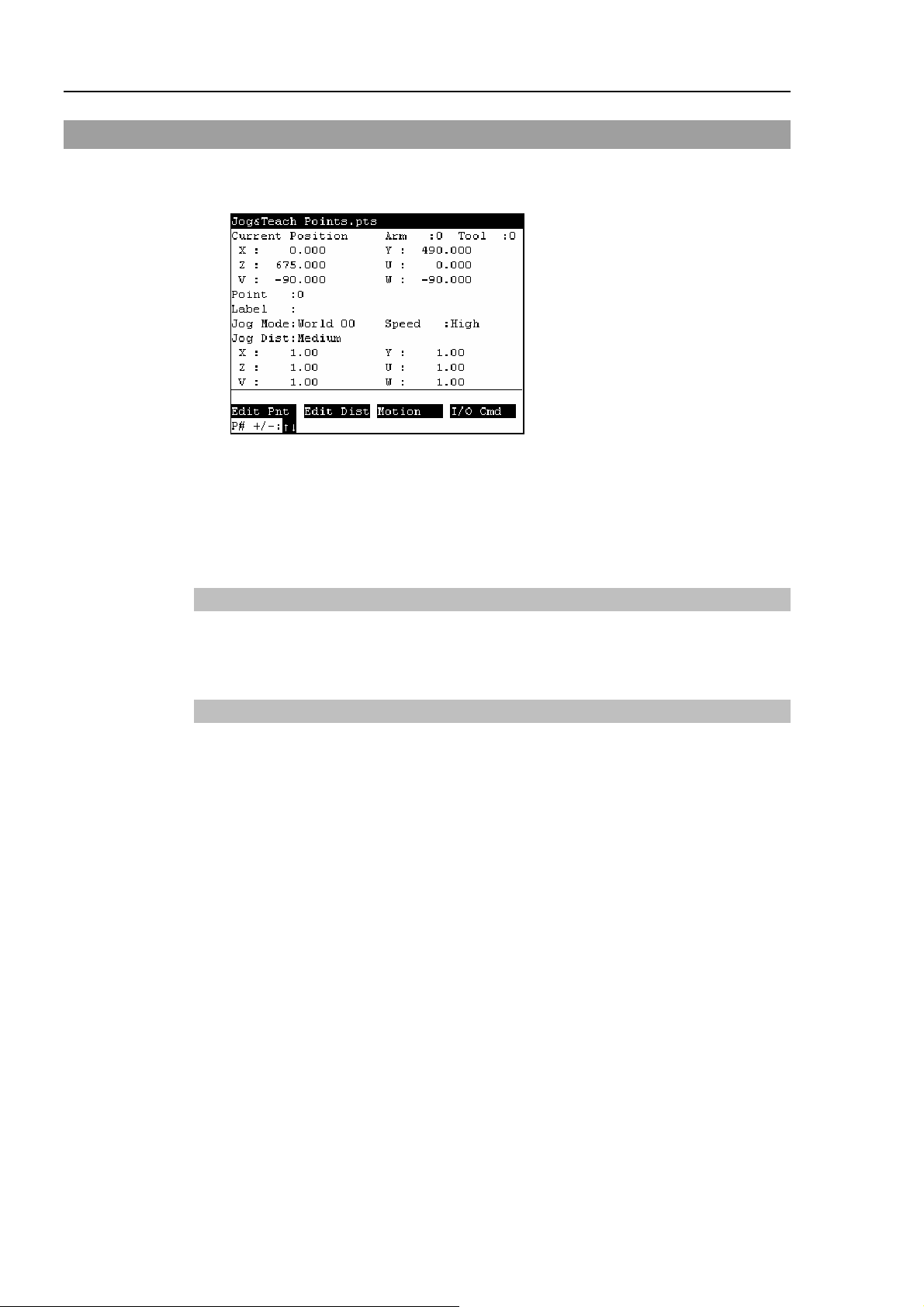
2.1 [Jog & Teach]
This section indicates settings in the [Jog&Teach] screen.
(1) Switch the mode selector key switch to “Teach” to display the following screen.
(2) Set the data items currently displayed in the [Jog&Teach] screen.
(See 2.1.1 to 2.1.6.)
(3) Note down the robot position. (See 2.1.9.)
(4) Back up the point data to a file. (See 2.1.10.)
2.1.1 Specifying Point No.
Change the value at [Point] using the <↑> and <↓> keys to specify a point No.
Changing the point No. changes the indication at [Label].
2.1.2 Specifying Jog Mode
Press the <Jog Mode> key and specify the [Jog Mode]. (World, Tool, Joint, ECP)
The default setting is “World”.
World : Jogs the robot along the X, Y, Z axes in the current local, tool, arm, and ECP.
For robots with 4 DOF, you can also jog U (roll).
For robots with 6 DOF, you can jog U (roll), V (pitch), and W (yaw). This is
the default setting.
Tool : Jogs the robot in the coordinate system defined by the current tool.
Joint : Jogs each joint of the robot.
A separate set of jog buttons will appear when using joint mode when using
non-Cartesian robots.
ECP : Jogs the robot along the axes of the coordinate system defined by the current
external control point. Coordinates are World coordinates.
32 TP1 Rev.5
Page 43

Operation 2. TEACH Mode
2.1.3 Specifying Jog Speed
Press the <Speed> key and select the speed at [Speed]. (Low, High)
: Low jog speed
Low
: High jog speed
High
2.1.4 Executing Step Jog
By step jog operation, the robot moves when the Jog key is pressed.
Set the distance that the robot moves beforehand.
(1) Press the <Jog Dist> key and select the distance at [Jog Dist].
: Long jog distance
Long
Medium
Short
: Medium jog distance
: Short jog distance
(2) To execute step jog, grip the Jog key with the enable switch held down.
2.1.5 Executing Continuous Jog
With continuous jog, the robot moves continuously while the Jog key is held down.
(1) Press the <Jog Dist> key and select “Cont Jog” at [Jog Dist].
(2) To execute continuous jog, grip the enable switch while pressing the Jog key.
2.1.6 ON/OFF
Specify On/Off for each joint.
When performing direct teaching (manually moving the robot by hand to perform
teaching), set the joint to Off.
Press the <Jog Dist> key and select “Free Joint” at [Jog Dist].
Set On/Off for each joint.
<+> key :
<−> key :
<F2> key :
<F3> key :
Lock : Sets the joint to Off.
Free : Sets the joint to On.
All Lock : Sets all joints to Off.
All Free : Sets all joints to On.
TP1 Rev.5 33
Page 44

Operation 2. TEACH Mode
2.1.7 Motor ON/OFF
Press the <Motor> key to switch the motor ON and OFF.
TIP
This can be executed at any time in TEACH mode.
)
2.1.8 Executing Return to Home
Press the <Home> key to return the robot to its home position.
TIP
This can be executed at any time in TEACH mode.
)
2.1.9 Teaching
The robot position is assigned to the specified point No.
(1) Press the <Teach> key.
(2) The following screen appears.
TIP
)
When the point number is already used, the following screen appears.
(3) Press the <OK> key to assign the point data.
(4) Press the <Save Points> key.
This can also be executed in the [Point Editor] screen.
34 TP1 Rev.5
Page 45

Operation 2. TEACH Mode
2.1.10 Saving Point Data to File
(1) Press the <Save Points> key.
(2) The following screen appears. Enter the file name, and press the <Enter> key.
(3) Press the <OK> key to save the positions to the file.
TIP
)
TIP
)
This can also be executed in the [Point Editor] screen.
2.1.11 Loading Point Data from File
(1) Press the <LoadPoints> key.
(2) The following screen appears. Move the cursor to select a file.
(3) Press the <OK> key to load the point data in the file memory.
This can also be executed in the [Point Editor] screen.
TP1 Rev.5 35
Page 46

Operation 2. TEACH Mode
2.2 Editing Points
This section indicates settings in the [Point Editor] screen.
(1) Press the <F1> key in the [Jog&Teach] screen. The following screen appears.
(2) Set the data items currently displayed in the [Point Editor] screen. (See 2.2.1 to
2.2.4.)
(3) Note down the robot position. (See 2.1.9.)
(4) Back up the point data to a file. (See 2.1.10.)
2.2.1 Specifying Point No.
(1) Specify the point number by changing the value in the [Point] using the <↑> and
<↓> keys.
Chang the point No. to change the indication at [Label].
(2) Press the <Enter> key.
(3) Press the <OK> key to apply the memory.
2.2.2 Changing Point Label
(1) Press the <F1> key and move the cursor to [Label].
(2) Enter the label name at [Label] to set the name.
(3) Press the <Enter> key.
(4) Press the <OK> key to apply the memory.
2.2.3 Changing Coordinate Data and Pose Flag
(1) Press the <F2> key and move the cursor to [Position: X].
(2) Move the cursor to each joint, and set the coordinate data/pose flag.
(3) Press the <Enter> key.
(4) Press the <OK> key to apply the memory.
2.2.4 Deleting Point Data
Press the <F3> key to delete the point data.
36 TP1 Rev.5
Page 47
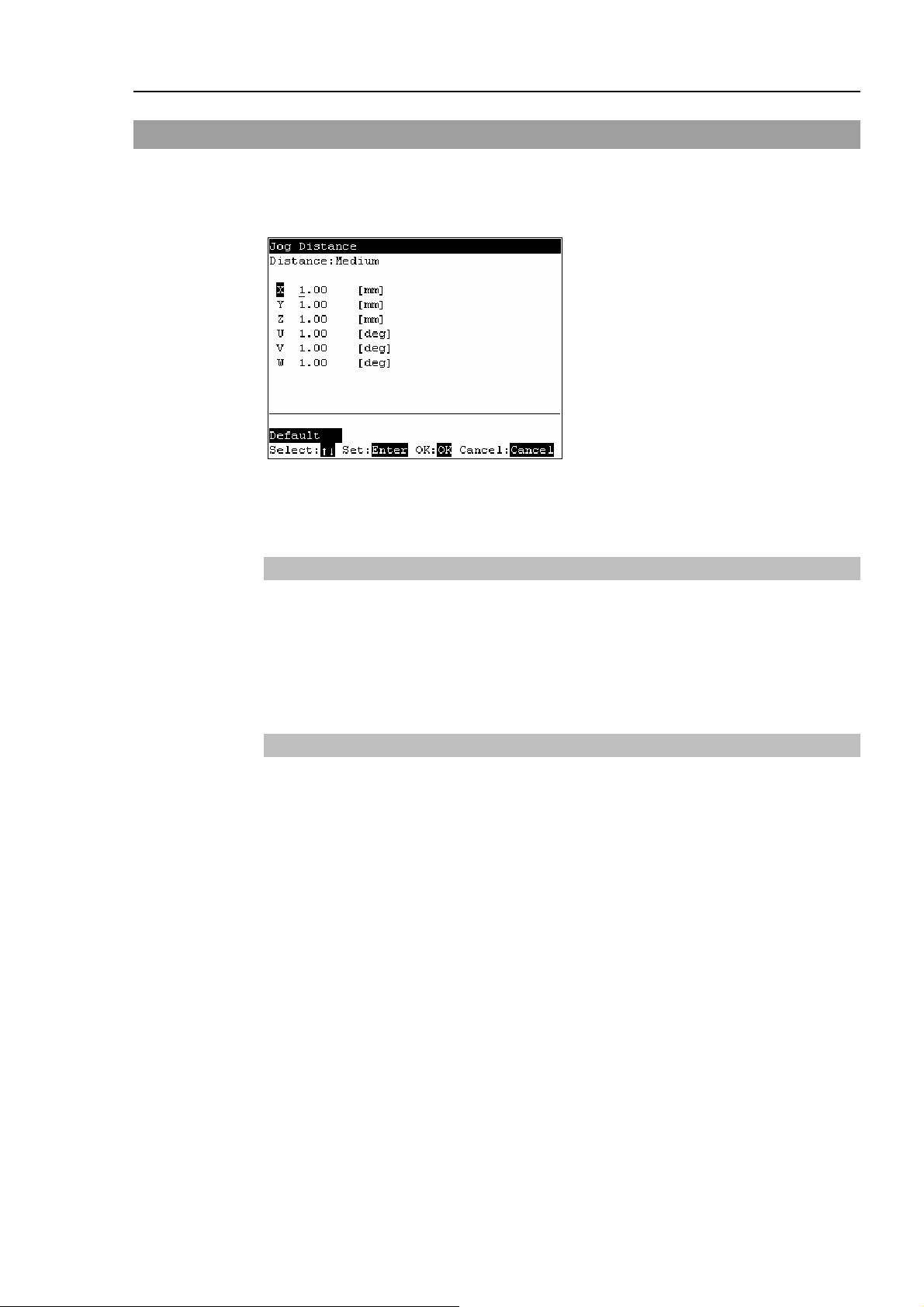
2.3 Changing Jog Distance Data
This section indicates settings in the [Jog Distance] screen.
Press the <F2> key in the [Jog&Teach] screen.
The following screen appears.
When a value has been changed, press the <Enter> key to apply the value, and be sure to
press the <OK> key to save the settings.
Operation 2. TEACH Mode
2.3.1 Changing Distance Data
Set the distance for each joint.
(1) Move the cursor to [Distance], press the <Jog Dist> key to select the distance (Long,
Medium, Short) that is to be changed.
(2) Move the cursor to each joint, and set the value.
2.3.2 Return Data to Defaults
Press the <F1> key to return jog distance data to their defaults.
TP1 Rev.5 37
Page 48

Operation 2. TEACH Mode
2.4 Arm/Tool/Local/ECP
This section indicates settings in the [Arm/Tool/Local/ECP] screen.
Press the <F5> or <F6> key in the [Jog&Teach] screen.
The following screen appears.
When a value has been changed, press the <Enter> key to apply the value, and be sure to
press the <OK> key to save the settings.
2.4.1 Changing Arm No.
(1) Press the <F1> key and move the cursor to [Arm].
(2) Set the arm number.
2.4.2 Changing Tool No.
(1) Press the <F2> key and move the cursor to [Tool].
(2) Set the tool number.
2.4.3 Changing Local No.
(1) Press the <F3> key and move the cursor to [Local].
(2) Set the local number.
2.4.4 Changing ECP No.
(1) Press the <F4> key and move the cursor to [ECP].
(2) Set the ECP No.
38 TP1 Rev.5
Page 49

2.5 Executing I/O Commands
This section indicates settings in the [I/O Command] screen.
Press the <F4> key in the [Jog&Teach] screen.
The following screen appears.
2.5.1 Switching Input/Output Status Display
Operation 2. TEACH Mode
Press the <F3> key to switch between the “Inputs” status and the “Outputs” status
display.
2.5.2 Output Bit ON/OFF
(1) Press the <F3> key to display the “Outputs” status.
(2) Move the cursor to the output bit that you want to change.
(3) Switch the ON/OFF status of the output bit.
<F1> key:
<F2> key:
On
Off
TP1 Rev.5 39
Page 50

Operation 2. TEACH Mode
2.6 Executing Motion Commands
2.6.1 E2 Series / G Series
This item indicates the procedure for executing motion commands when using E2 series /
G series robots.
(1) Press the <F3> key in the [Jog&Teach] screen.
The following screen appears.
Move the cursor to the desired motion command, and press the <OK> key.
(2) The motion command screen appears.
Set the information required for the command, and press the <Enter> key to apply
the settings.
(3) Press the <OK> key to execute the command.
2.6.2 PS Series
This item indicates the procedure for executing motion commands when using PS series
robots.
(1) Press the <F3> key in the [Jog&Teach] screen. The following screen appears.
Move the cursor to the desired motion command, and press the <OK> key.
(2) The motion command screen appears.
Set the information required for the command, and press the <Enter> key to apply
the settings.
(3) Press the <OK> key to execute the command.
40 TP1 Rev.5
Page 51

2.7 Calibrating Origin : E2 Series / G Series
This item indicates the procedure to calibrate the origin when using E2 series / G series
robots.
Follow the procedure below to display the [Calibration] screen.
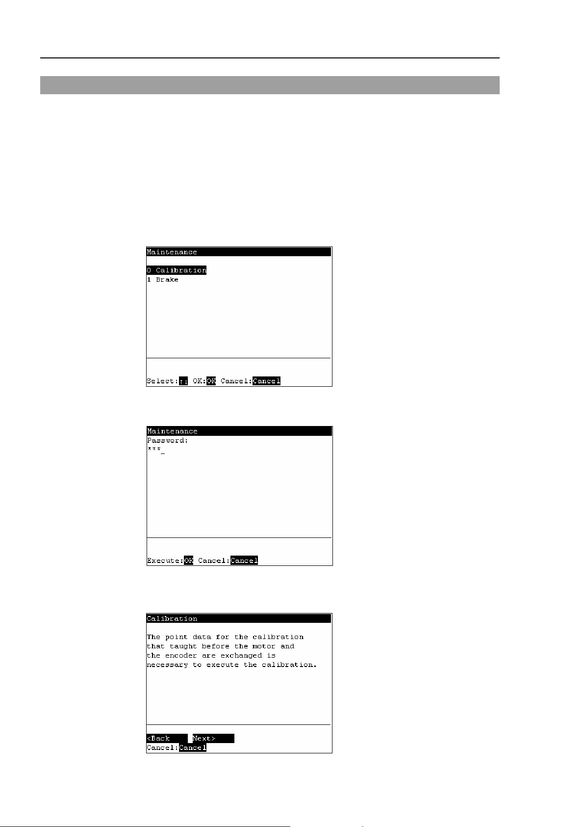
(1) Press the <F8> key in the [Jog&Teach] screen
(2) The following screen appears.
Move the cursor to “0 calibration” and press the <OK> key.
NOTE
)
The following screen appears when the password is set up.
Enter the password (1 to 16 characters) and press the <OK> key.
Operation 2. TEACH Mode
For password setting, refer to Operation 4. Password Setup.
(3) The following calibration menu screen appears.
TP1 Rev.5 41
Page 52

Operation 2. TEACH Mode
2.7.1 Calibration Procedures (E2 Series)
■
Calibrate Joint #3 first when aligning origins of more than one joint. When Joint
CAUTION
#3 is too low, it may collide with peripheral equipment during the calibration of
the other joints and may damage the peripheral equipment.
The same calibration procedure is used for all joints. Follow the steps below to calibrate
each joint.
When calibrating Joint #4, you must calibrate Joint #3 and #4 at the same time. You
cannot calibrate Joint #4 alone because of the structure of the Manipulator.
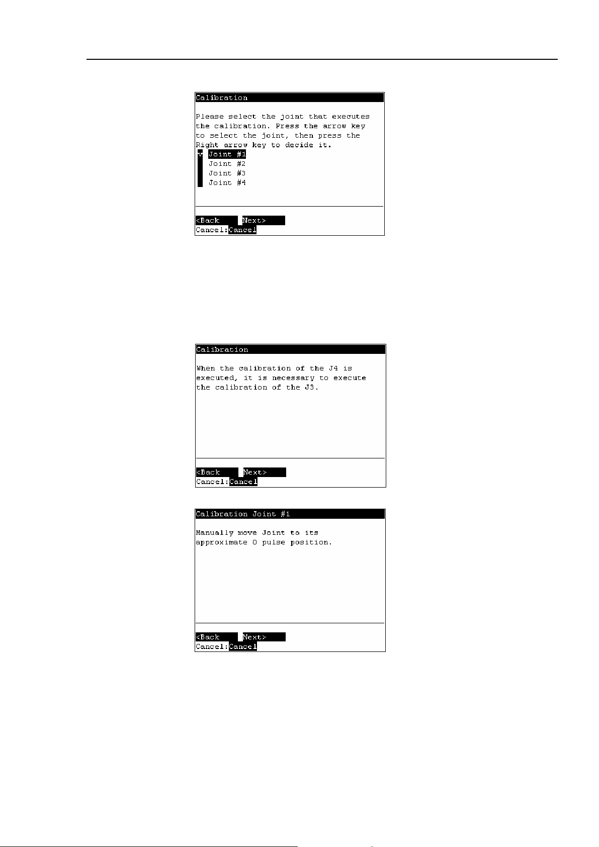
(1) In the [Calibration] screen, move the cursor to “0 Joint #1-4”, and press the <OK>
key.
(2) The following screen appears. Press the <F2> key.
(3) The following screen appears.
42 TP1 Rev.5
Page 53

Operation 2. TEACH Mode
Move the cursor to the joint to calibrate. Press the <→> key to select the joint and
press the <F2> key.
<→> key : Joint selection
<←> key : Joint selection reset
The following screen appears when selection Joint #4 and Joint #3 is selected
automatically.
(4) When a message appears regarding the capacitor charge, leave the power ON for 3
or more minutes to sufficiently charge the capacitor. Press the <F2> key to display
the following screen.
(5) The following screen appears.
TP1 Rev.5 43
Page 54

Operation 2. TEACH Mode
d
(6) Manually move the joint that needs origin alignment to its approximate 0 pulse
position.
0 pulse position of Joint #1 : position aligned with X-axis in Manipulator coordinate
system
0 pulse
0 pulse position of Joint #2 : position where Arms #1 and #2 are in a straight line
(Regardless of the Joint #1 direction)
0 pulse
0 pulse position of Joint #3 : upper limit position in motion range
Upper limit:
0 pulse
0 pulse position of Joint #4 : position where the flat surface on the shaft faces towar
the tip of Arm #2
0 pulse
44 TP1 Rev.5
Page 55

Operation 2. TEACH Mode
A
(7) Press the <F2> key. The following screen appears.
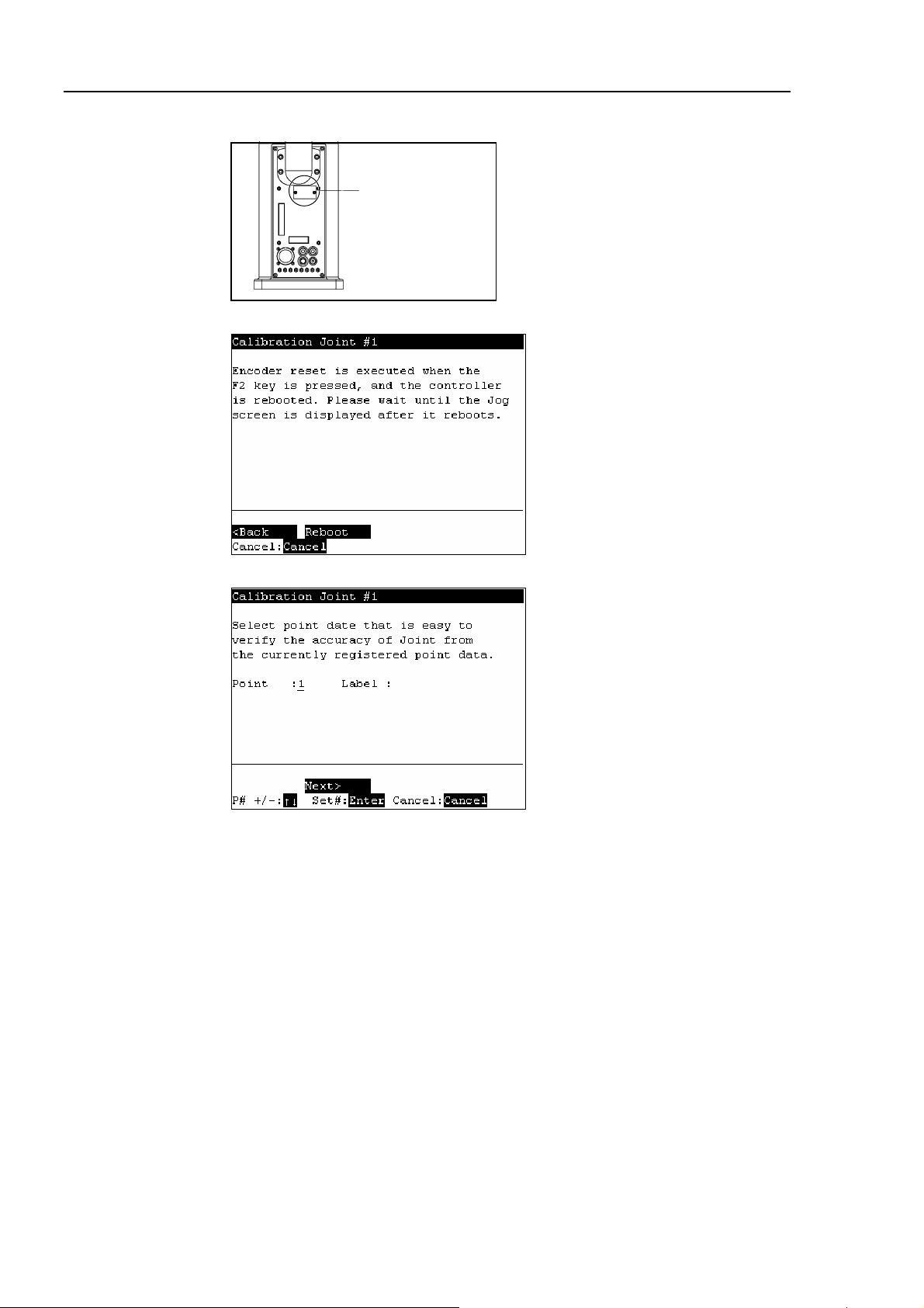
(8) Remove the acrylic panel on the sensor monitor on the base connector plate.
crylic Panel
(9) Set one of the DIP switches (SD1)“1” to “4” corresponding to the calibrating Joint to
its ON position.
Sensor monitor
DIP switch
(SD1)
Reset switch
(SW1)
(10) Press and hold the reset switch (SW1) for 1 or more seconds.
(11) Press the <F2> key to display the following screen.
TP1 Rev.5 45
Page 56
Operation 2. TEACH Mode
A
(12) Turn OFF the DIP switch and mount the acrylic panel on the sensor monitor.
crylic Panel
(13) Press the <F2> key. The following screen appears. Press the <F2> key again.
NOTE
)
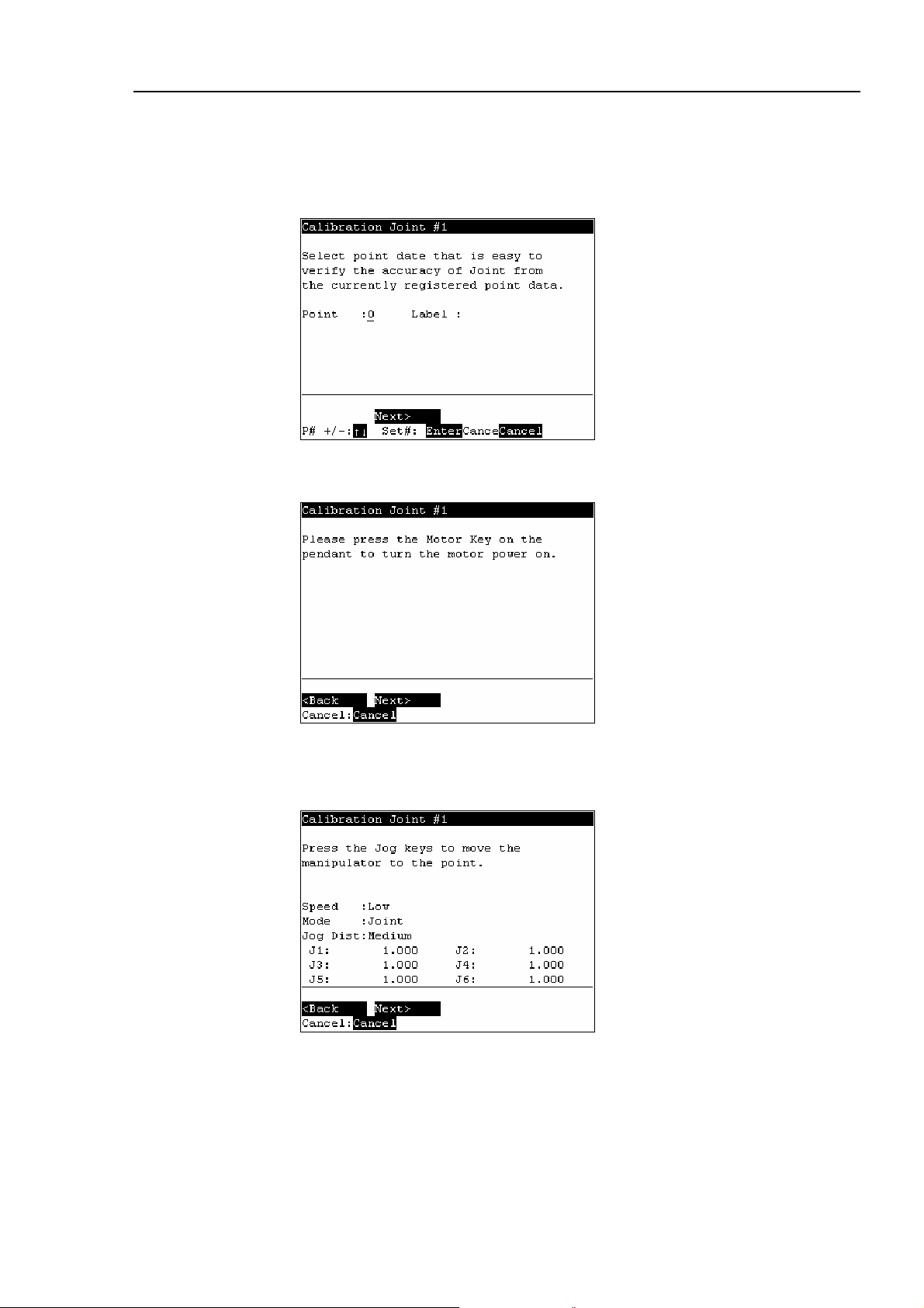
(14) Controller reboots and the following screen appears.
Select one of the currently registered point data that is easy to verify the accuracy of
the calibrating joint using the <↑> and <↓> keys, and press the <Enter> key.
Press the <F2> key.
The Manipulator does not move to the exact point because the specified origin is
determined visually. Although the error is less than one revolution of the motor, be
careful not to allow the Manipulator to interfere with peripheral equipment.
One revolution of the Joint #1 motor: ± 4.5 degrees
One revolution of the Joint #2 motor: ± 7.2 degrees
One revolution of the Joint #3 motor: ± 13.4 mm
One revolution of the Joint #4 motor: ± 22.5 degrees
46 TP1 Rev.5
Page 57

Operation 2. TEACH Mode
(15) The following screen appears.
Press the <Motor> key to turn ON the motor. Press the <F2> key.
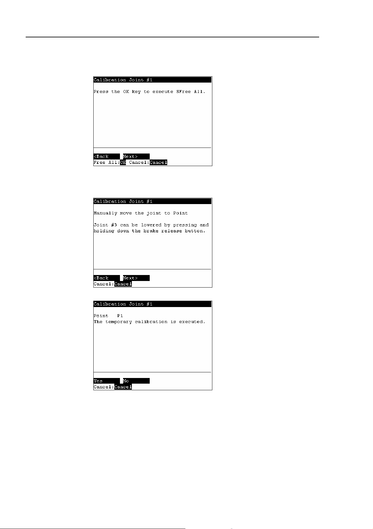
(16) The following screen appears. Press the <OK> key to stop the servo control for all
joints to enable the joints to be moved manually.
Press the <F2> key to display the following screen.
(17) The following screen appears. Manually move and position the joint that needs
origin alignment while pushing the Joint #3 brake release button and lowering Joint
#3. Press the <F2> key.
TP1 Rev.5 47
Page 58

Operation 2. TEACH Mode
(18) The following screen appears. Press the <F1> key to execute temporary calibration.
The following screen appears after executing the temporary calibration.
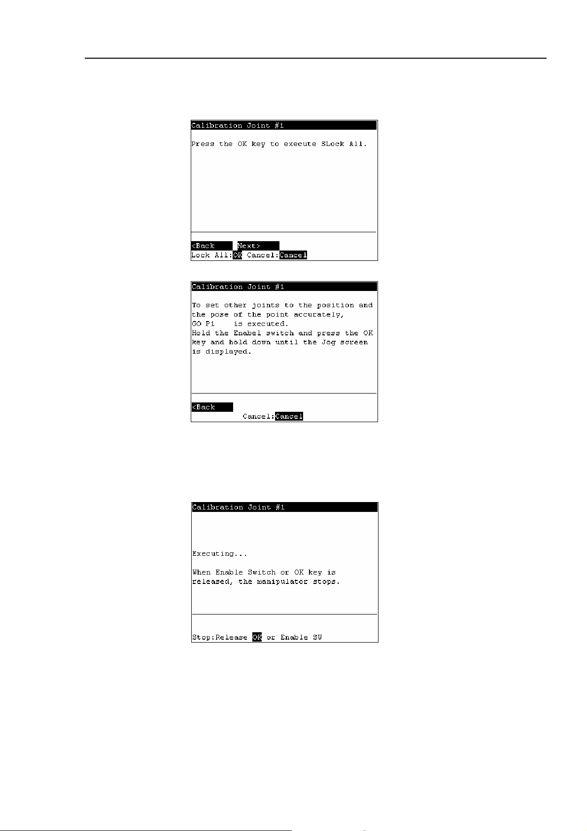
Press the <OK> key to servo control all joints.
Press the <F2> key.
(19) The following screen appears.
Move the joints except the calibrated joints to the point data position by the motion
command. For an example the motion command will be executed to Joint #1 and
#2 when Joint #4 is calibrated.
Press the <OK> key while gripping the enable switch to execute Go P1.
48 TP1 Rev.5
Page 59

Operation 2. TEACH Mode
The following screen appears during Go P1 execution.
(20) The following screen appears after Go P1 execution.
Set the calibrated joints to the selected point data position accurately by the jog
motion.
Press the Jog key to move the joint to the basic pose as accurate as possible.
Press the <F2> key.
(21) The following screen appears. Press the <F1> key.
TP1 Rev.5 49
Page 60

Operation 2. TEACH Mode
(22) The origin calibration completed screen appears.
NOTE
For righty or lefty setting, refer to 2.7.3 Setting Righty / Lefty.
)
2.7.2 Calibration Procedures (G Series)
■
Calibrate Joint #3 first when aligning origins of more than one joint. When Joint
CAUTION
#3 is too low, it may collide with peripheral equipment during the calibration of
the other joints and may damage the peripheral equipment.
The same calibration procedure is used for all joints. Follow the steps below to calibrate
each joint.
When calibrating Joint #4, you must calibrate Joint #3 and #4 at the same time. You
cannot calibrate Joint #4 alone because of the structure of the Manipulator.
(1) In the [Calibration] screen, move the cursor to “0 Joint #1-4”, and press the <OK>
key.
(2) The following screen appears. Press the <F2> key.
50 TP1 Rev.5
Page 61
Operation 2. TEACH Mode
(3) The following screen appears.
Move the cursor to the joint to calibrate. Press the <→> key to select the joint and
press the <F2> key.
<→> key : Joint selection
<←> key : Joint selection reset
The following screen appears when selection Joint #4 and Joint #3 is selected
automatically.
(4) The following screen appears.
TP1 Rev.5 51
Page 62

Operation 2. TEACH Mode
d
(5) Manually move the joint that needs origin alignment to its approximate 0 pulse
position.
0 pulse position of Joint #1 : position aligned with X-axis in Manipulator coordinate
system
0 pulse
0 pulse position of Joint #2 : position where Arms #1 and #2 are in a straight line
(Regardless of the Joint #1 direction)
0 pulse
0 pulse position of Joint #3 : upper limit position in motion range
Upper limit:
0 pulse
0 pulse position of Joint #4 : position where the flat surface on the shaft faces towar
the tip of Arm #2
0 pulse
52 TP1 Rev.5
Page 63
Operation 2. TEACH Mode
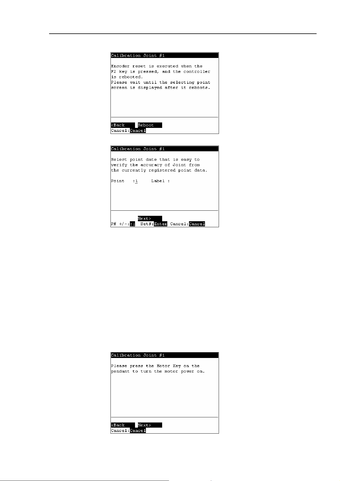
(6) Press the <F2> key. The following screen appears. Press the <F2> key again.
(7) Controller reboots and the following screen appears.
NOTE
)
Select one of the currently registered point data that is easy to verify the accuracy of
the calibrating joint using the <↑> and <↓> keys, and press the <Enter> key.
Press the <F2> key.
The Manipulator does not move to the exact point because the specified origin is
determined visually. Although the error is less than one revolution of the motor, be
careful not to allow the Manipulator to interfere with peripheral equipment.
One revolution of the Joint #1 motor: ± 4.5 degrees
One revolution of the Joint #2 motor: ± 7.2 degrees
One revolution of the Joint #3 motor: Z180 : ± 11.94 mm
Z330 : ± 23.87 mm
One revolution of the Joint #4 motor: ± 24.06 degrees
(8) The following screen appears.
Press the <Motor> key to turn ON the motor. Press the <F2> key.
TP1 Rev.5 53
Page 64
Operation 2. TEACH Mode
(9) The following screen appears. Press the <OK> key to stop the servo control for all
joints to enable the joints to be moved manually.
Press the <F2> key to display the following screen.
(10) The following screen appears. Manually move and position the joint that needs
origin alignment while pushing the Joint #3 brake release button and lowering Joint
#3. Press the <F2> key.
(11) The following screen appears. Press the <F1> key to execute temporary calibration.
54 TP1 Rev.5
Page 65
Operation 2. TEACH Mode
The following screen appears after executing the temporary calibration.
Press the <OK> key to servo control all joints.
Press the <F2> key.
(12) The following screen appears.
Move the joints except the calibrated joints to the point data position by the motion
command. For an example the motion command will be executed to Joint #1 and
#2 when Joint #4 is calibrated.
Press the <OK> key while gripping the enable switch to execute Go P1.
The following screen appears during Go P1 execution.
TP1 Rev.5 55
Page 66

Operation 2. TEACH Mode
(13) The following screen appears after Go P1 execution.
Set the calibrated joints to the selected point data position accurately by the jog
motion.
Press the Jog key to move the joint to the basic pose as accurate as possible.
Press the <F2> key.
(14) The following screen appears. Press the <F1> key.
NOTE
)
(15) The origin calibration completed screen appears.
For righty or lefty setting, refer to 2.7.3 Setting Righty / Lefty.
56 TP1 Rev.5
Page 67

Operation 2. TEACH Mode
2.7.3 Setting Righty / Lefty (E2 Series / G Sereis)
(1) In the [Calibration] screen, move the cursor to “Righty/Lefty”, and press the <OK>
key.
(2) The following screen appears. Select one of the point data in the accessible area
that is easy to verify the accuracy for both right and left arm orientations using the
<↑> and <↓> keys and press the <Enter> key.
Press the <F2>key.
(3) The following screen appears. Press the <Motor> key to turn ON the motor.
Press the <F2> key.
TP1 Rev.5 57
Page 68
Operation 2. TEACH Mode
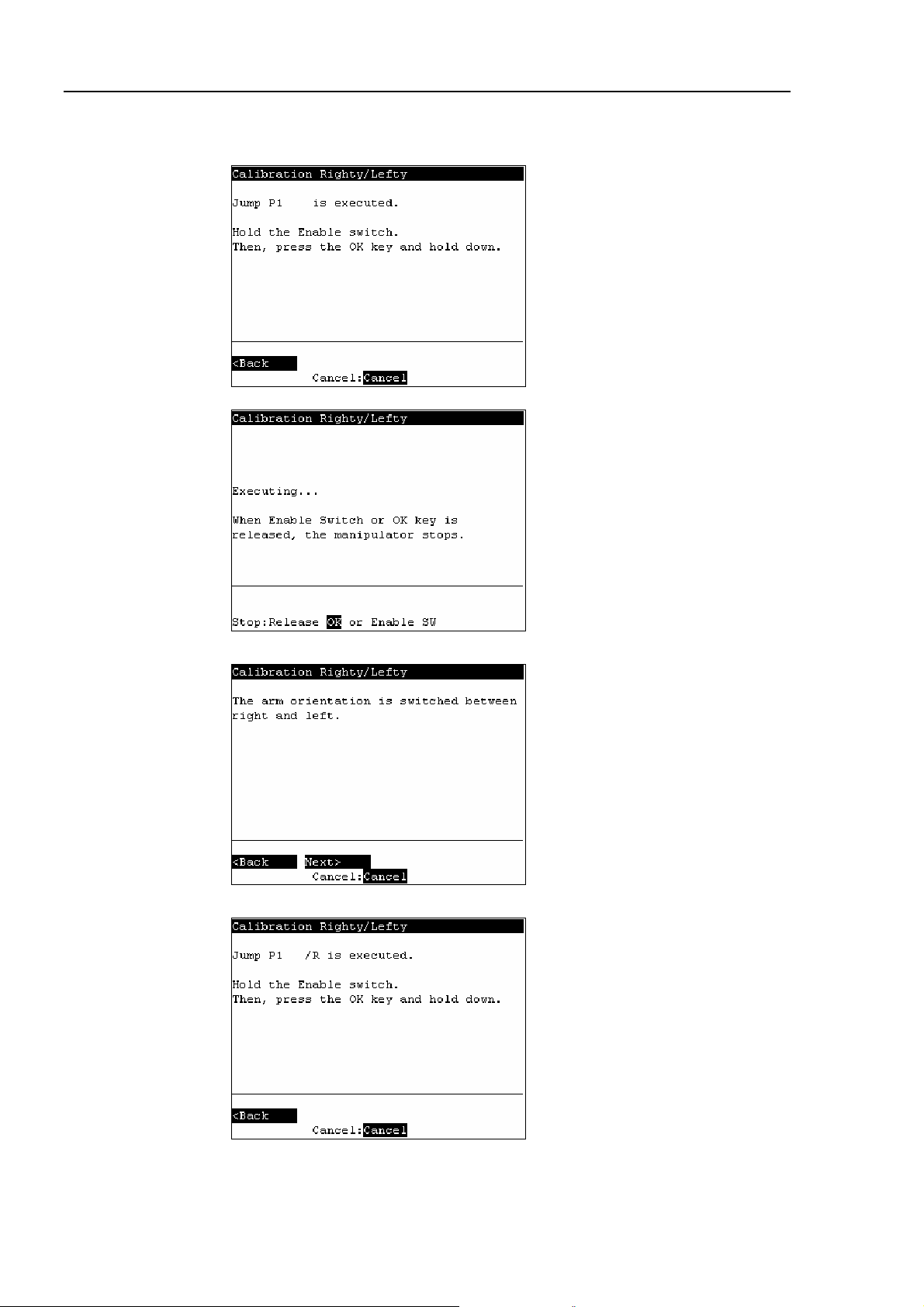
(4) Continue to press the <OK> key with the enable switch held down to execute Jump
P1.
The following screen appears during Jump P1 execution.
(5) The following screen appears after Jump P1 execution. Press the <F2> key.
(6) The following screen appears.
Switch the arm orientation between right and left and move to the same point.
Press the <OK> key while gripping the enable switch to execute Jump P1.
58 TP1 Rev.5
Page 69

Operation 2. TEACH Mode
The following screen appears during Jump P1.
(7) The following screen appears after executing Jump P1.
Set the calibrated joints to the basic pose accurately by the jog key.
Press the <F2> key.
(8) The following screen appears.
Press the <F1> key.
(9) The origin calibration completed screen appears.
TP1 Rev.5 59
Page 70
Operation 2. TEACH Mode
2.8 Calibrating Origin : PS Series
This section indicates the procedure to calibrate the origin when using PS series robots.
The same calibration procedure is used for all joints. Follow the steps below to calibrate
each joint.
When calibrating Joint #5, you must calibrate Joint #5 and #6 at the same time. You
cannot calibrate Joint #5 alone because of the structure of the Manipulator.
(1) Press the <F8> key in the [Jog&Teach] screen.
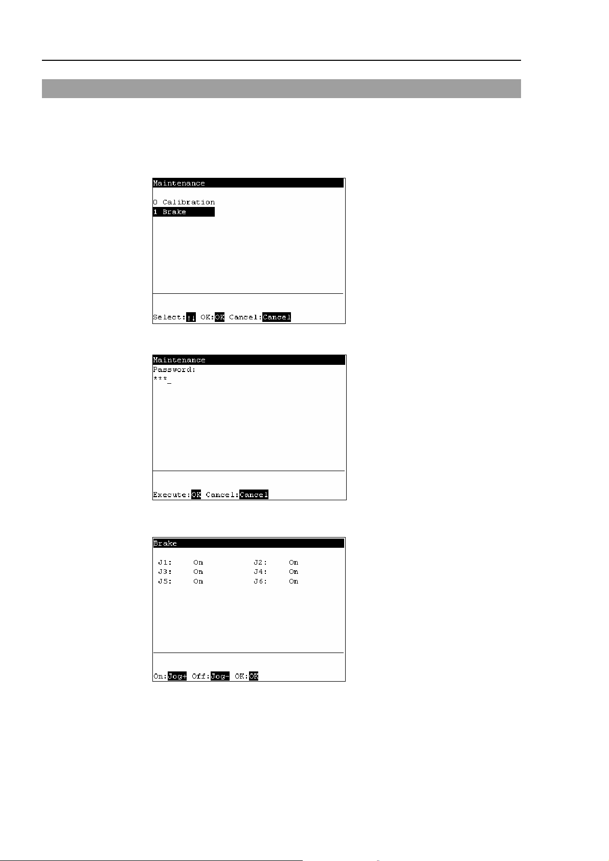
(2) The following screen appears.
Move the cursor to “0 calibration” and press the <OK> key.
NOTE
The following screen appears when the password is set up.
)
Enter the password (1 to 16 characters) and press the <OK> key.
For password setting, refer to Operation 4. Password Setup.
(3) The following screen appears. Press the <F2> key.
60 TP1 Rev.5
Page 71

Operation 2. TEACH Mode
(4) The following screen appears.
Move the cursor to the joint to calibrate. Press the <→> key to select the joint and
press the <F2> key.
<→> key : Joint selection
<←> key : Joint selection reset
The following screen appears when selecting Joint #5 and Joint #6 is selected
automatically.
(5) The following screen appears. Press the <F2> key.
TP1 Rev.5 61
Page 72

Operation 2. TEACH Mode
(6) The Controller reboots and the following screen appears.
Press the <Motor> key to turn ON the motor. Press the <F2> key.
(7) The following screen appears.
Press the Jog key and move the joint close to 0 pulse.
When the joint does not move to 0 pulse, move the joint to the set basic pose marked
in Setup & Operation Setting the Basic Pose for Calibration in the Manipulator
manual.
Press the <F2> key.
(8) The following screen appears. Press the <F2> key.
62 TP1 Rev.5
Page 73
Operation 2. TEACH Mode
(9) Select a point data that is easy to verify the accuracy of the joint that needs origin
alignment from the currently registered point data using the <↑> and <↓> keys, and
press the <Enter> key.
Press the <F2> key.
(10) The following screen appears.
Press the <Motor> key to turn ON the motor. Press the <F2> key.
(11) The following screen appears.
Press the Jog key to move the joint to the basic pose as accurate as possible.
Press the <F2> key.
TP1 Rev.5 63
Page 74

Operation 2. TEACH Mode
(12) The following screen appears. Press the <F1> key to execute temporary calibration.
(13) The following screen appears after executing the temporary calibration.
Move the joints except the calibrated joints to the point data position by the motion
command. For an example the motion command will be executed to Joint #1 to #4
when Joint #5 is calibrated.
Press the <OK> key while gripping the enable switch to execute Go P0.
The following screen appears during Go P0 execution.
64 TP1 Rev.5
Page 75

Operation 2. TEACH Mode
(14) The following screen appears after Go P0 execution.
Move the calibrated joints to the selected point data position accurately by the jog
motion. For an example, Joint #5 and #6 is the calibrated joints.
Press the Jog key to move the joint to the basic pose as accurate as possible.
Press the <F2> key.
(15) The following screen appears. Press the <F1> key.
(16) The origin calibration completed screen appears.
TP1 Rev.5 65
Page 76
Operation 2. TEACH Mode
2.9 Releasing Brake (PS series only)
This section indicates the brake ON / OFF switching for each joint.
(1) Press the <F8> key in the [Jog&Teach] screen.
(2) The following screen appears.
Move the cursor to “1 Brake” and press the <OK> key.
The following screen appears when the password is set up.
Enter the password (1 to 16 characters) and press the <OK> key.
For password setting, refer to Operation 4. Password Setup.
(3) The following screen appears.
66 TP1 Rev.5
Page 77

To turn the brake ON
(4) Press the <Jog+> key of the joint whose brake On/Off setting is to be switched.
(5) Press the <OK> key. The brake is locked.
To turn the brake OFF
(4) Press the <Jog-> key of the joint whose brake On/Off setting is to be switched.
(5) The brake Off confirmation message appears. Confirm the message and press the
Operation 2. TEACH Mode
<F1> key.
(6) The brake is released, and the specified joint moves manually.
TP1 Rev.5 67
Page 78

Operation 3. AUTO Mode
3. AUTO Mode
Switch the mode selector key switch to “Auto” to enter the AUTO mode. In this mode,
jog, teaching, operation commands, I/O commands, and other operations and commands
can be executed using the teaching pendant.
Note, however, that the program cluster cannot be executed.
Auto Mode
Print Panel
I/O monitor
Memory I/O monitor
Tasks
System history
Program mode
Open Program
3.1 Program Command
3.2 I/O Monitor
3.3 Memory I/O Monitor
3.4 Task Monitor
3.5 System History
3.6 Program Mode
3.6.1 Opening Programs
Input
Save
Exit
Search
Jump
Auto Mode
Backup/restore
Saving controller
Displaying the date
Adjusting the
brightness and
Error messages
Screen name
See item
Building projects
Backing up projects
Restoring projects
Importing files
Exporting files
System backup
Restoring the system
Changing the
Configuration
Display language
Updating system
Program editor
Enabling
execution
3.6.2 Building Projects
3.6.3 Backing up Projects
3.6.4 Restoring Projects
3.6.5 Importing Files
3.6.6 Exporting Files
3.6.7 Backing up the System
3.6.8 Restoring the System
3.6.9 Changing Speed
3.6.10 Configuration
3.6.11 Changing the Display
3.6.12 Updating the System
3.7 Backup/Restore
3.8 Saving Controller Statuses
3.9 Displaying Date and Time
3.10 Adjusting Brightness and
3.11 Error Messages
68 TP1 Rev.5
Page 79

Operation 3. AUTO Mode
Switch the mode selector key switch to “Auto” to display the [Print] screen. Follow the
description on the screen and press the <F4> key to display the [Main Menu] screen.
TIP
)
Menus with “...” at the end have following procedures after selecting the menu and
cannot be executed only by pressing the <OK> key.
TP1 Rev.5 69
Page 80

Operation 3. AUTO Mode
3.1 Program Command Display
This screen displays messages from the program and requests responses.
The [Print] screen appears when the mode selector key switch is switched to “Auto”.
To display the [Print] screen from the [Main Menu] screen, move the cursor to [Print
Panel], and press the <OK> key.
When only a message appears
Program Example :
PRINT #24,“Test Print”
The [Main Menu] screen appears.
<F4>
When a message appears and a response is requested
Program Example :
PRINT #24,“Test Print”
INPUT #24,a$
Input the response to the message at the cursor position. (Characters or numerical
values)
Deletes all entered characters or numerical values.
<F1>
The [Main Menu] screen appears.
<F4>
70 TP1 Rev.5
Page 81
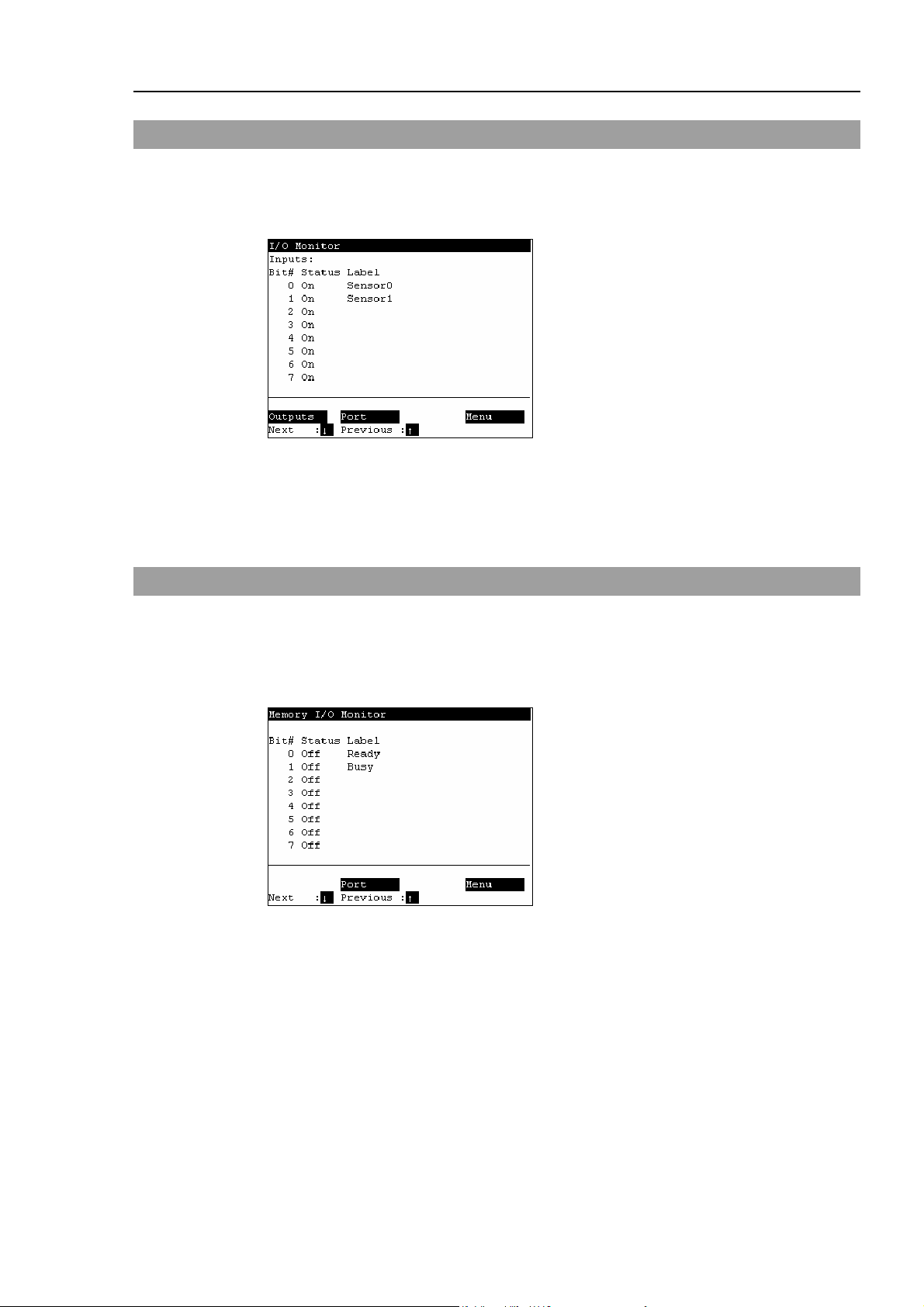
3.2 I/O Monitor
This screen displays the bit status of I/O.
In the [Main Menu] screen, move the cursor to [1 I/O Monitor], and press the <OK> key.
I/O status (Inputs, bit units)
“*” (asterisk) is displayed before the label name for remote setting display to separate
remote setting and I/O label.
Switches between Inputs and Outputs.
<F1>
Switches the I/O bit status display (Bit units or port units).
<F2>
Operation 3. AUTO Mode
3.3 Memory I/O Monitor
This screen displays the bit status of memory I/O.
In the [Main Menu] screen, move the cursor to [2 Memory I/O Monitor], and press the
<OK> key.
Memory I/O status (bit units)
Switches the I/O bit status display (Bit units or port units).
<F2>
TP1 Rev.5 71
Page 82

Operation 3. AUTO Mode
3.4 Task Monitor
This screen displays the status of tasks.
In the [Main Menu] screen, move the cursor to [3 Task Monitor], and press the <OK> key.
When the task name is too long to display the whole name, a tilde is attached at the end of
the task name as “LongTaskNa~”.
When the task is “NoPause task”, “*P” is attached at the end of the task name.
When the task is “NoEmgAbort task”, “*E” is attached at the end of the task name.
Displays the line number and task name in the program specified by the cursor.
<F1>
Displays the status and line number of all tasks in the program specified by the cursor.
<F2>
72 TP1 Rev.5
Page 83

3.5 System History
This screen displays a history of errors, operations and warnings that occurred in the past.
In the [Main Menu] screen, move the cursor to [4 System History], and press the <OK>
key.
Displays the item type, Number, joint #, task #, date, and time in this order from the left.
[System History] main screen
Displays the details of the error specified by the cursor.
<F2>
Operation 3. AUTO Mode
TP1 Rev.5 73
Page 84

Operation 3. AUTO Mode
3.6 Program Mode
This section indicates settings in the [Program Mode] screen.
Follow the procedure below to display the [Program Mode] screen.
(1) In the [Main Menu] screen, move the cursor to [5 Program Mode...], and press the
<OK> key.
(2) The following screen appears.
[Program Mode] screen
TIP
)
TIP
)
Move the cursor to the last line and press the <↓> key to display the following
screen.
[Program Mode] screen (next screen)
Menus with “...” at the end have following procedures after selecting the menu and
cannot be executed only by pressing the <OK> key.
When a password is set up, the following screen appears before displaying the
[Program Mode] screen.
Enter the password (1 to 16 characters). Press the <OK> key.
For password setting, refer to Operation 4. Password Setup.
74 TP1 Rev.5
Page 85

Operation 3. AUTO Mode
3.6.1 Open Programs
(1) In the [Program Mode] screen, move the cursor to [0 Open Program...], and press the
<OK> key.
The screen that appears next differs according to the number of files that are
currently saved.
When there is only one file
Select the “function” and press the <OK> key to open the file.
When there are two or more files
Select the file, and press the <OK> key to open the file.
(2) The following screen appears.
Program edit screen (example)
TP1 Rev.5 75
Page 86

Operation 3. AUTO Mode
T
V
Entering programs
The character and numerical value input modes are switched according to whether the
“Alph” lamp is ON or OFF.
Press the <Alph/Num> key to switch “Alph” between ON or OFF.
Alph Mode Key Function
OFF Numerical value input mode
ON Character input mode
Common
Operation panel (excerpt)
ext/Numerical
alue Input keys
0 to 9
Numerical value input
− (minus)
. (period)
ABC to WXYZ Character input
SP (space) Space input
a/A Switching between
lowercase and uppercase
Sym Symbol input
CLR Clears numerical values
and text.
Enter Determines numerical
values and characters.
<Alph/Num> key
<CLR> key
<Enter> key
Arrow keys
How to enter characters
Multiple characters are assigned to each button of the text/numerical value input keys.
The character changes by each press of the button.
Example : When the <ABC / 2> key is pressed (when “Alph” is ON)
The character changes in order “a” → “b” → “c”.
To continue input using the same button, press the <→> key to move the cursor forward.
Example : Input “Teach 170”.
(1) Input “Teach”.
Press the <Alph / Num> key to light “Alph”.
Press the <a/A / −> key to switch to input of uppercase characters.
Press the <TUV / 8> key once.
Press the <a/A / −> key to switch to input of lowercase characters.
Press the <DEF / 3> key twice.
Press the <ABC / 2> key once. Press the <→> key to move the cursor forward.
Press the <ABC / 2> key three times.
Press the <GHI / 4> key twice.
(2) Enter a space.
Press the <Space / 1> key once.
76 TP1 Rev.5
Page 87
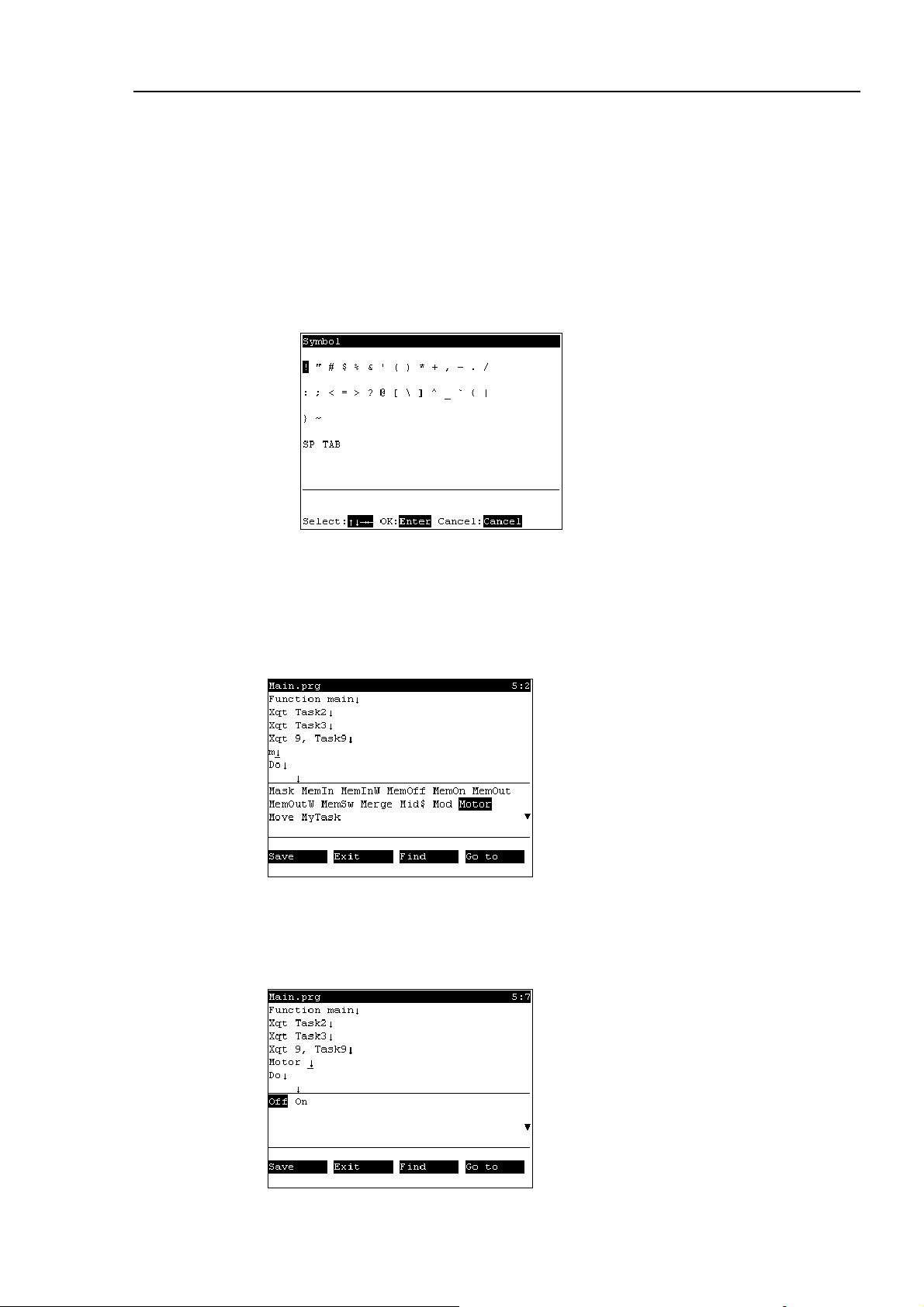
Operation 3. AUTO Mode
(3) Enter “170”.
Press the <Alph / Num> key to turn “Alph” OFF.
Press the <Space / 1> key once.
Press the <PQRS / 7> key once.
Press the <Sym / 0> key once.
How to enter symbols
(1) Press the <Alph / Num> key to light “Alph”.
(2) Press the <Sym /0> key to display the following screen.
(3) Select the symbol, and press the <Enter> key.
Entering text using key words
Candidate command statements are anticipated and displayed from text that is currently
being entered. Move the cursor, select the desired command statement, and press the
<Enter> key.
Entering text using syntax help
If you enter a space ( ) , . = > following a specific command statement, such as
“MOTOR” or “POWER”, candidate characters to enter appear.
Move the cursor, select the desired character, and press the <Enter> key.
TP1 Rev.5 77
Page 88

Operation 3. AUTO Mode
m
Save programs
Save programs after editing the programs.
(1) Press the <F1> key to save the program file. The following screen appears during
saving the program file.
(2) After the save ends, the screen returns to the program edit screen.
Exiting program edit
Finish editing the program.
(1) Press the <F2> key to exit the program file.
(2) After the save ends, the screen returns to the program edit screen.
The following screen appears when the program file has been changed but not saved.
<F1>
<F2>
Saves the file, and returns to the program edit screen.
Returns to the [Program Mode] screen without saving the changes of the progra
file.
78 TP1 Rev.5
Page 89

Operation 3. AUTO Mode
Search character strings
Search for character strings in the program.
(1) Press the <F3> key. The following screen appears.
Enter the character string to search, and press the <Enter> key.
<↓>
<F1>
Displays a list of search text strings.
Changes the search order (descending, ascending).
The following screen appears during the search.
(2) If the character string is found, the cursor moves to the start of that character string.
If the character string is not found, the cursor position does not change.
Jump
This section describes settings that can be made in the [Go to] screen.
In the program edit screen, press the <F4> key. The following screen appears.
TP1 Rev.5 79
Page 90

Operation 3. AUTO Mode
Jumping to a specified line in the program
(1) Move the cursor to “Line”, and press the <Enter> key.
(2) The following screen appears.
Enter a numerical value at [Enter line number] to specify the line number.
(3) Move the cursor to the specified line.
Jumping to a “function” in the program file
(1) Move the cursor to [Function], and press the <Enter> key.
(2) The following screen appears.
Move the cursor to the desired “function” and press the <OK> key.
The following screen appears during execution.
(3) The specified “function” screen appears.
80 TP1 Rev.5
Page 91

Operation 3. AUTO Mode
3.6.2 Building Projects
Follow the procedure below to build projects.
(1) In the [Program Mode] screen, move the cursor to [1 Build Project...], and press the
<OK> key. Building of the project is started. The following screen appears
during execution.
(2)
When building is successful
The following screen appears after the project building is successfully completed.
When building fails
The error message list appears.
Move the cursor to the desired error, and press the <OK> key.
The file with the error appears, and the error line is indicated by the cursor.
TP1 Rev.5 81
Page 92

Operation 3. AUTO Mode
3.6.3 Backing up Projects
Backs up projects to USB memory.
(1) Insert the USB memory into the Controller.
(2) In the [Program Mode] screen, move the cursor to [2 Backup Project...], and press
the <OK> key.
(3) The following screen appears.
Press the <OK> key to execute the project backup.
Saves the project to the folder “\EpsonRC50\Projects” in the USB memory.
<OK>
<Cancel>
When a project of the same name exists in the USB memory, the following screen
appears.
Overwrites the project.
Cancels the project backup.
82 TP1 Rev.5
Page 93

Operation 3. AUTO Mode
3.6.4 Restore Projects
Restores projects backed up in USB memory to the Controller.
(1) Insert the USB memory into the Controller.
(2) In the [Program Mode] screen, move the cursor to [3 Restore Project...], and press
the <OK> key.
(3) The following screen appears. Press the <OK> key.
(4) The following screen appears.
Displays the project list in the folder “\EpsonRC50\Projects” in the USB memory.
Move the cursor to the desired project, and press the <OK> key.
(5) The following screen appears. Press the <F1> key.
(6) Executes the project restore.
TP1 Rev.5 83
Page 94

Operation 3. AUTO Mode
3.6.5 Import Files
Imports “Prg”, “Inc” and “Pts” files in the USB memory to projects in the Controller.
Only files of the same name as those that exist in projects can be imported.
(1) Insert the USB memory into the Controller.
(2) In the [Program Mode] screen, move the cursor to [4 Import File...], and press the
<OK> key.
(3) The following screen appears.
Move the cursor to the file to import, and press the <OK> key.
<Enter>
<F1>
Displays the hierarchy one level below the selected folder.
Displays the hierarchy one level above the selected folder.
(4) Executes the file import.
When a file of the same name already exists, the following screen appears.
<F1>
<F2>
Overwrites the file.
Moves to the [Program Mode] screen.
84 TP1 Rev.5
Page 95

Operation 3. AUTO Mode
3.6.6 Export Files
Exports “Prg”, “Inc” and “Pts” files in projects in the Controller to the USB memory.
(1) Insert the USB memory into the Controller.
(2) In the [Program Mode] screen, move the cursor to [5 Export File...], and press the
<OK> key.
(3) The following screen appears.
Move the cursor to the file to export, and press the <OK> key.
TIP
)
(4) The following screen appears. Press the <F2> key.
When <OK> key is pressed without specifying a folder, the backup file is stored
directly in the USB memory. For prcedure to specify th folder, refer to (5).
(5) The following screen appears.
Move the cursor to export and press the <OK> key.
<Enter>
<F1>
TP1 Rev.5 85
Displays the hierarchy one level below the selected folder.
Displays the hierarchy one level above the selected folder.
Page 96
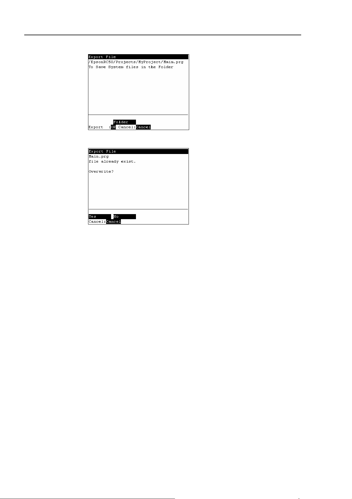
Operation 3. AUTO Mode
(6) The following screen appears. Press the <OK> key.
(7) Executes the file export.
When a file of the same name already exists, the following screen appears.
<F1>
<F2>
Overwrites the file.
Moves to the [Program Mode] screen.
86 TP1 Rev.5
Page 97

Operation 3. AUTO Mode
3.6.7 Backup System
Backs up system files in the Controller to the USB memory.
(1) Insert the USB memory into the Controller.
(2) In the [Program Mode] screen, move the cursor to [6 System Backup...], and press
the <OK> key.
(3) The following screen appears.
Enter the file name and press the <Enter> key.
TIP
)
(4) The following screen appears. Press the <OK> key.
When <OK> key is pressed without specifying a folder, the backup file is stored
directly in the USB memory. For procedure to specify the folder, refer to (5).
(5) The following screen appears.
Move the cursor to the folder to save the backup data and press the <OK> key.
TP1 Rev.5 87
Page 98

Operation 3. AUTO Mode
(6) The following screen appears. Press the <OK> key to execute the system backup.
When a file of the same name already exists, the following screen appears.
<F1>
<F2>
Overwrites the file.
Moves to the [Program Mode] screen.
(7) After execution is completed, the following screen appears
88 TP1 Rev.5
Page 99

Operation 3. AUTO Mode
3.6.8 Restore System
Restores system files backed up in USB memory to the Controller.
(1) Insert the USB memory into the Controller.
(2) In the [Program Mode] screen, move the cursor to [7 System Restore...], and press
the <OK> key.
(3) The following screen appears.
When you restore the robot name, serial number, and the calibration data with the
basic Controller settings, move the cursor to [Robot name, serial #, calibration] and
press the <→> key.
When you restore the project with the basic Controller settings, move the cursor to
[Project] and press the <→> key.
(4) Press the <OK> key
(5) The following screen appears. Press the <OK> key.
(6) The following screen appears. Move the cursor to the desired folder.
Press the <Enter> key.
TP1 Rev.5 89
Page 100
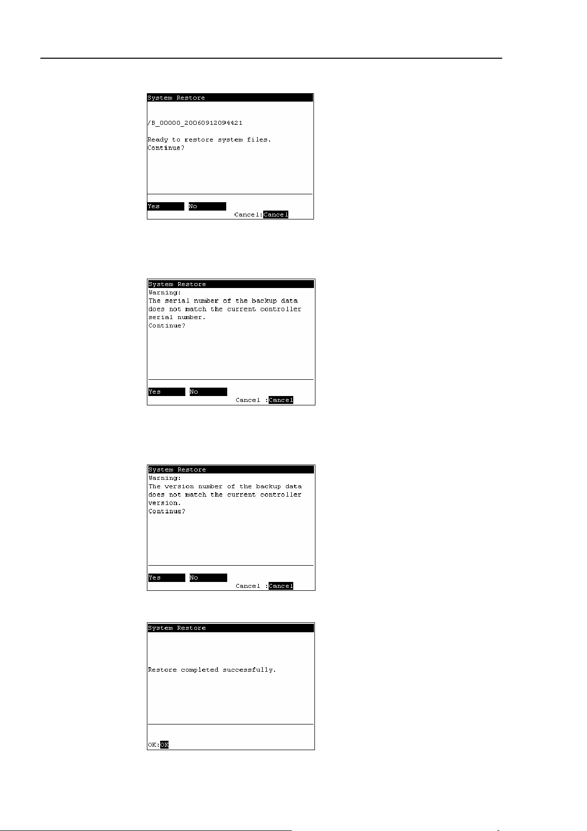
Operation 3. AUTO Mode
(7) The following screen appears. Press the <F1> key to start the restore.
When the Controller serial number does not match the serial number of the selected
Controller setting data, the following screen appears. To continue, press the <F1>
key.
When the Controller system software version does not match the version of the
selected Controller setting data, the following screen appears. To continue, press
the <F1> key.
(8) After execution is completed, the following screen appears.
Press the <OK> key and the Controller reboots.
90 TP1 Rev.5
 Loading...