

Page 1
CONFIDENTIAL
TM-U950/U950P
Using this online technical guide
The words on the left side of this screen are bookmarks for all the
topics in this guide.
Use the scroll bar next to the bookmarks to find any topic you
want. Click a bookmark to instantly jump to its topic. (If you wish,
you can increase the size of the bookmark area by dragging the
dividing bar to the right.)
Use the scroll bar on the right side of this screen to move through
the text.
Use the zoom tools to magnify or reduce the page display.
Click the Find button if you want to search for a particular term.
(However, using the bookmarks is usually quicker.)
Technical Manual
Complete online documentation for Acrobat Reader is located in the Help directory for Acrobat Reader.
Return to main menu
Page 2

Technical manual
TM-U950/TM-U950P
Copied Date 199 , ,
Copied by
English
4005789
Page 3

CONFIDENTIAL
EPSON
SEIKO EPSON CORPORATION
Printed in Japan E96010130-0000SE
Page 4

Confidential
CONFIDENTIALITY AGREEMENT
BY USING THIS DOCUMENT, YOU AGREE TO ABIDE BY THE TERMS OF THIS
AGREEMENT. PLEASE RETURN THIS DOCUMENT IMMEDIATELY IF YOU DO NOT AGREE
TO THESE TERMS.
1. This document contains confidential, prop rietary informat ion of Seiko Epson Corporation or
its affiliates. You must keep such information confidential. If the user is a business entity or
organization, you must limit disclosure to those of your employees, agents and contractors
who have a need to know and who are also bound by obligations of confidentiality.
2. On the earlier of (a) termination of your relationship with Seiko Epson, or (b) Seiko Epson’s
request, you must stop using the confidential information. You must then return or destroy
the information, as directed by Seiko Epson.
3. If a court, arbitrator, government agency or the like orders you to disclose any confidential
information, you must immediately notify Seiko Epson. You agree to give Seiko Epson
reasonable cooperation and assistance in resisting disclosure.
4. You may use confidential information only for the purpose of operating or servicing the
products to which the document relates, unless you obtain the pr ior written consent of Seik o
Epson for some other use.
5. Seiko Epson warrants that it has the right to disclose the confidential information. SEIKO
EPSON MAKES NO OTHER WARRANTIES CONCERNING THE CONFIDENTIAL
INFORMATION OR ANY OTHER INFORMATION IN THE DOCUMENT, INCLUDING
(WITHOUT LIMITATION) ANY WARRANTY OF TITLE OR NON-INFRINGEMENT.
Seiko Epson has no liability for loss or damage arising from or relating to your use of or
reliance on the information on the document.
6. You may not reproduce, store or transmit the confidential information in any form or by any
means (electronic, mechanical, photocopying, recording, or otherwise) without the prior
written permission of Seiko Epson.
7. Your obligations under this Agreement are in addition to any other legal obligations. Seiko
Epson does not waive any right under this Agreement by failing to exercise it. The laws of
Japan apply to this Agreement.
Page 5

CONFIDENTIAL
FCC CLASS A
FCC Compliance Statement
For American Users
This equipment has been tested an d found to compl y with the limits for a Cla ss A digita l devic e, pursuant to Pa rt 15 of
the FCC Rules. These limits are designed to provide reasonable protection against harmful interference when the
equipment is operated in a commercial environment.
This equipment generates, uses, and can radiate radio frequency energy and, if not installed and used in accordance
with the instruction manual, may cause harmful interference to radio communications. Operation of this equipment in
a residential area is likely to cause harmful interference, in which case the user will be required to correct the
interference at his own expense.
WARNING
The connection of a non-shielded printer interface cable to this printer will invalidate the FCC Verification of this
device and may cause interference levels which exceed the limits established by the FCC for this equipment.
You are cautioned that changes or modifications not expre ssly approved by the party r esponsible for compliance could
void your authority to operate the equipment.
TM-U950/TM-U950P Technical Manual
FOR CANADIAN USERS
This digital apparatus does not exceed the Class A limits for radio noise emissions from digital apparatus as set out in
the radio interference regulations of the Canadian Department of Communications.
Le présent appareil numérique n’émet pas de bruits radioélectriques dépassant les limites applicables aux appareils
numériques de Class A prescrites dans le règlement sur le brouillage radioélectrique édicté par le Ministère des
Communications du Canada.
GEREÄUSCHPEGEL
Gemäß der Dritten Verordrung zu m Gerätesich erheits gecsetz (M aschinen lärminfo rmation s- Verordn ung-3. GS GV) ist
der arbeitsplatzbezogene Geräusch-Emissionswert kleiner als 70 dB(A ) (basierend auf ISO 7779).
Rev. A i
Page 6

CONFIDENTIAL
Introduction
The TM-U950 printer is an ESC/POS® compatible high-performance point of sale (POS) printer
which can handle receipt, journal, and slip paper. There are two models: the TM-U950 and the
TM-U950P. The TM-U950P has a parallel interface. Differences between the two models are
noted throughout this manual.
The main features of the TM-U950 and TM-U950P printers are the following:
❏Usable with a wide range of slip paper types.
❏Non-protruding interface connectors integrated in the body of the printer.
❏Bidirectional logic seek for high throughput.
❏Paper feed pitch of 1/144 inch.
❏Integrated printer buffer with 32 byte or 2 KB capacity.
❏Slip paper eject sensor.
❏ASB (Automatic Status Back) function to send the printer status automatically.
❏EPSON intelligent module connection (Not available on the TM-U950P).
❏EPSON customer display series connection (Not available on the TM-U950P).
❏Optional Magnetic Ink Character Recognition (MICR) reader that enables the printer to
perform consecutive reading and p rocessing of MICR characters and pri nting endorsements
(not available for the TM-U950P).
ii Rev. A
Page 7

CONFIDENTIAL
About This Manual
❏
Chapter 1 provides general specifications and hardware configuration information.
❏
Chapter 2 provides general operating principles and printer mechanism configuration
information.
❏
Chapter 3 provides handling and maintenance information.
❏
Chapter 4 provides troubleshooting information.
❏
Chapter 5 provides printer disassembly, assembly, and adjustment instructions.
❏
Chapter 6 (Appendix) provides circuit board and exploded diagrams.
Notes and Cautions
Note:
Notes have important information and useful tips on the operation of your printer.
TM-U950/TM-U950P Technical Manual
CAUTION:
Cautions must be observed to avoid damage to your equipment.
Rev. A iii
Page 8

CONFIDENTIAL
Revision Sheet
Revision Page Altered Item and Contents
Rev. A
iv Rev. A
Page 9

CONFIDENTIAL
Contents
TM-U950/TM-U950P Technical Manual
Chapter 1
Features ...................................................................................................................................................................................... 1-1
General Specifications ..............................................................................................................................................................1-3
Printing Specifications.......................................................... ......................... .......................... ... .......................... ............ 1-3
Character Specifications .................................................................................................................................................. 1-4
Paper Specifications ......................................................................................................................................................... 1-5
Paper Roll Feed Mechanism ............................................................................................................................................1-9
Journal Paper Take-up Mechanism ................................................................................................................................1-9
Auto-cutter ........................................................................................................................................................................1-9
Electrical Specifications ....................................................................................................................................................1-9
Stamp .................................................................................................................................................................................. 1-10
Ink Ribbon .........................................................................................................................................................................1-10
Dimensions, Weight, Finish ....................................................... ......................... .......................... ... .......................... ..... 1-11
Environmental Specificati o ns ........................................................... .......................... ......................... .... .......................1-11
Reliability ........................................................................................................................................................................... 1-12
Hardware Configuration .........................................................................................................................................................1-13
Main Unit Configuration ............................................................ ......................... .......................... ... .......................... ..... 1-13
Main Unit Specifications .............. ... .... .... ......................... ......................... .......................... .... ......................... ................1-14
Connectors ......................................................................................................................................................................... 1-17
Interface .............................................................................................................................................................................. 1-19
Switches and Buttons ....................................................................................................................................................... 1-27
Functions .................................................................................................................................................................................... 1-31
Error Processing ................................................................................................................................................................1-31
Self-test ............................................................................................................................................................................... 1-32
Hexadecimal Dumping ....................................................................................................................................................1-32
Printing Operation ................ .......................... ......................... .......................... ... .......................... ......................... ......... 1-33
Options ....................................................................................................................................................................................... 1-34
AC Adapter (PS-150) ........................................................................................................................................................ 1-34
Journal Lock ......................................................................................................................................................................1-34
Features and General Specifications
Chapter 2
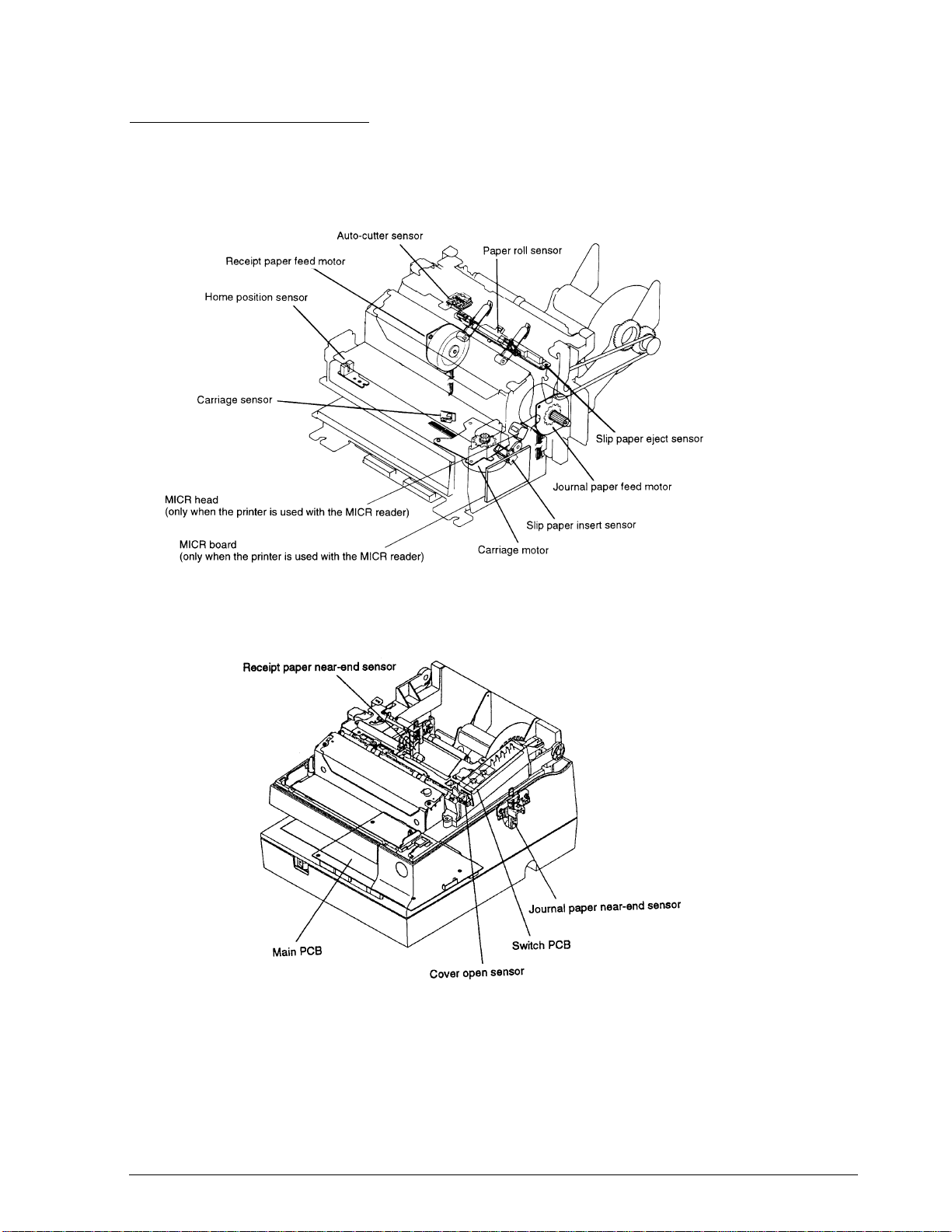
Printer Mechanism Components ............................................................................................................................................ 2-1
Printer Mechanism Operating Principles ..............................................................................................................................2-2
Printing Assembly............................................... ... .......................... ......................... ......................... .... ......................... ..2-2
Sensor Assemblies.............................................................................................................................................................2-4
Paper Feed Assembly .......................................................................................................................................................2-9
Slip Paper Assembly ........................................................................................................................................................2-12
MICR Reader Assembly (for printers with a MICR reader) (not available for the TM-U950P) ........................... 2-16
Ribbon Feed Assembly ....................................................................................................................................................2-18
Stamp Assembly (for printers with a stamp assembly) ..............................................................................................2-19
Auto-cutter Assembly ...................................................................................................................................................... 2-20
Paper Roll Take-up Assembly ........................................................................................................................................ 2-23
Electrical Circuitry Operating Principles .............................................................................................................................. 2-25
Hardware Configuration ................................................................................................................................................. 2-25
Main Board Operating Principle .................................... ......................... .......................... ......................... .... ................2-30
MICR Board Operating Principle (on printers with a MICR reader) (not available for the TM-U950P) ............ 2-49
Mechanism Configuration and Operating Principles
Rev. A v
Page 10

CONFIDENTIAL
Chapter 3 Handling and Maintenance
Handling .....................................................................................................................................................................................3-1
Handling Precautions .......................................................................................................................................................3-1
Loading the Paper Rolls ...................................................................................................................................................3-2
Removing the Paper Rolls ................................. ... .... ......................... .... ......................... .......................... ........................3-4
Inserting Slip Paper and Printing on Slip Paper ...........................................................................................................3-5
Printing on Personal Checks (only on printers with a MICR reader) (not available for the TM-U950P) ............3-6
Installing and Removing the Ribbon Cassette ..............................................................................................................3-8
Inserting the Stamp Set .....................................................................................................................................................3-9
Mounting the Power Switch Cover ................................................................................................................................3-10
Journal Lock Key Handling .............................................................................................................................................3-10
Removing the Jammed Paper ..........................................................................................................................................3-10
Maintenance ...............................................................................................................................................................................3-13
Periodic Checks .................................................................................................................................................................3-13
Cleaning ..............................................................................................................................................................................3-13
Lubrication .........................................................................................................................................................................3-14
Tool List ..............................................................................................................................................................................3-17
Measuring Equipment List ....................... .... ......................... .......................... ... .......................... ......................... ..........3-18
Lubricant List .....................................................................................................................................................................3-18
Chapter 4 Troubleshooting
Troubleshooting ........................................................................................................................................................................4-1
Self-test ................................................................................................................................................................................4-1
Troubleshooting Flowchart ..............................................................................................................................................4-4
Troubleshooting Tables ....................................................................................................................................................4-12
Major Part Replacements .........................................................................................................................................................4-23
Fuse replacement ...............................................................................................................................................................4-23
Print Head Unit Replacement .........................................................................................................................................4-23
Cutter Blade Replacement ................................................................................................................................................4-23
Error Types And Countermeasures ........................................................................................................................................4-24
Chapter 5 Disassembly, Assembly, and Adjustment
Small Part Specifications ..........................................................................................................................................................5-1
Actual Size E-type Retaining Rings ................................................................................................................................5-1
Disassembly ...............................................................................................................................................................................5-2
Replacing the Print Head Unit ........................................................................................................................................5-3
Replacing the Cutter Blade ..............................................................................................................................................5-5
Printer Mechanism Unit Assembly .........................................................................................................................................5-6
Sub-assembly A: Detector-Paper Assembly...................................................................................................................5-7
Sub-assembly B: Paper Guide-Upper Unit As sem bl y .................................................................. ......................... .... ..5-8
Sub-assembly C: Paper Guide-Lower Unit Assembly..................................................................................................5-10
Sub-assembly D: Cutter Motor Mount Plate Assembly ...............................................................................................5-12
Sub-assembly E: Roller-Paper Ho ld Asse mbly........................ ......................... .... .......................... ......................... ......5-12
Sub-assembly F: Cutter Frame Assemb ly............................. .... .... ... .......................... ......................... .......................... ..5-13
Sub-assembly G: Detector-Slip Ejection Assembly.......................................................................................................5-13
Sub-assembly H: Auto-cutter Unit Assembly ...............................................................................................................5-14
Sub-assembly I: Pulley Base-Carriage Transmission Assembly .................................................................................5-17
Sub-assembly J: Carriage-Head Assembly ....................................................................................................................5-17
Sub-assembly K: Assembling the MICR Head Hold er Ass em bly (for printe rs with a MICR rea der) .................5-18
Sub-assembly L-(1): Frame-Carriage Unit Assembly (for printers without a MICR reader) .................................5-22
Sub-assembly L-(2): Frame Carriage Unit Assembly (for printers with a MICR reader) ........................................5-27
Sub-assembly M: Frame-Inner Assembly.......................................................................................................................5-35
Sub-assembly N: Detector-Slip Insertion Assembly .....................................................................................................5-36
Sub-assembly O: Solenoid J/S Changeov er As semb ly............... ......................... .... ......................... .......................... ..5-36
Sub-assembly P: Paper Guide-Slip-Lower Assembly...................................................................................................5-37
vi Rev. A
Page 11

CONFIDENTIAL
Sub-assembly Q: Frame-Paper Take-up Assembly......................................................................................................5-38
Sub-assembly R: Assembling the motor-paper guide-J assembly (for printers with a MICR reader).................. 5-39
Main Assembly (Part 1) ...................................................................................................................................................5-40
Adjustments ......................................................................................................................................................................5-53
Main Assembly (Part 2) ...................................................................................................................................................5-59
Whole Unit Assembly .............................................................................................................................................................. 5-65
Sub-assembly A: N.E. Detector-J Assembly and N.E. Detector-R Assembly...........................................................5-65
Sub-assembly B: Holder-Switc h Circuit Board As semb ly ....................... .... ......................... .......................... ............ 5-67
Sub-assembly C: Journal Lock and Cover-Paper Take-up Assembly (Option) ...................................................... 5-68
Sub-assembly D: Cover Paper Take-up ......................................................................................................................... 5-69
Main Assembly .......................... ... .... .......................... ......................... .... ......................... ......................... .......................... ... ..5-70
Main Assembly 1: Main Circuit Board, P-ROM, and Plate-Main Mounting ...........................................................5-70
Main Assembly 2: FFC, Power Cable, and Plate-Circuit Board Attachment ...........................................................5-71
Main Assembly 3: Printer Mechanism Assembly Attachment on Plate-Main ........................................................5-72
Main Assembly 4: N.E. Detector-R and -J Assemblies Attachment .......................................................................... 5-73
Main Assembly 5: Printer Mechanism Assembly Attachment on Case-Lower Assembly .................................... 5-75
Main Assembly 6: Case-Upper Assembly Mounting .................................................................................................. 5-76
Main Assembly 7: Cover-Face and Cover-Main Assembly Attachment .................................................................. 5-77
Main Assembly 8: Cover-ROM Attachment ................................................................................................................. 5-78
Adjustments .............................................................................................................................................................................. 5-79
Adjustment G: Adjusting the Paper Roll Near-end Detector Location ....................................................................5-79
Adjustment H: Detector-Slip Insertion Assembly Threshold Value Adjustment....................................................5-81
Adjustment I: MICR mechanism check..........................................................................................................................5-83
TM-U950/TM-U950P Technical Manual
Chapter 6 Appendix
Electrical Circuit Drawings......................................................................................................................................................6-1
Circuit 1..............................................................................................................................................................................6-2
Circuit 2..............................................................................................................................................................................6-3
Circuit 3..............................................................................................................................................................................6-4
Circuit 4..............................................................................................................................................................................6-5
Circuit 5..............................................................................................................................................................................6-6
Circuit 6..............................................................................................................................................................................6-7
Circuit 7..............................................................................................................................................................................6-7
Circuit 8..............................................................................................................................................................................6-8
Main Unit Circuit Drawing for TM-U950.....................................................................................................................6-9
Main Unit Circuit Drawing for TM-U950P..................................................................................................................6-10
MICR Board (for printers with a MICR reader) (Not available for the TM-U950P) .............................................. 6-11
Parallel Interface Circuit Board Diagram..................................................................................................................... 6-12
Main Circuit Board Parts Layout for TM-U950................................. ......................... .......................... ... ....................6-13
Main Circuit Board Parts Layout for TM-U950 P........................... .......................... ......................... .... .......................6-14
Parallel Interace Circuit Board Parts Layout................................................................................................................ 6-15
Overall Exploded Diagrams...................................................... ......................... .......................... ... .......................... ..... 6-16
Lubrication Points Diagram for Printers Without a MICR Reader (1/3) ................................................................6-26
Lubrication Points Diagram for Printers Without a MICR Reader (2/3) ................................................................6-27
Lubrication Points Diagram for Printers Without a MICR Reader (3/3) ................................................................6-28
Lubrication Points Diagram for Printers With a MICR Reader (1/4)...................................................................... 6-29
Lubrication Points Diagram for Printers With a MICR Reader (2/4)...................................................................... 6-30
Lubrication Points Diagram for Printers With a MICR Reader (3/4)...................................................................... 6-31
Lubrication Points Diagram for Printers With a MICR Reader (4/4)...................................................................... 6-32
Rev. A vii
Page 12

CONFIDENTIAL
Chapter 1
Features and General Specifications
Features
The TM-U950 printer is an ESC/POS™ compatible high-performance point of sale (POS) printer
which can handle receipt, journal, and slip paper. There are two models: the TM-U950 and the
TM-U950P. The TM-U950P has a parallel interface. Differences between the two models are
noted throughout this manual.
The main features of the TM-U950 and TM-U950P printers are the following:
❏ Usable with a wide range of slip paper types.
❏ Non-protruding interface connectors integrated in the body of the printer.
❏ Bidirectional logic seek for high throughput.
TM-U950/U950P Technical Manual
❏ Paper feed pitch of 1/144 inch.
❏ Integrated printer buffer with 32 byte or 2 KB capacity.
❏ Slip paper eject sensor.
❏ ASB (Automatic Status Back) function to send the printer status automatically.
❏ EPSON intelligent module connection (Not available on the TM-U950P).
❏ EPSON customer display series connection (Not available on the TM-U950P).
❏ Optional Mag netic Ink Cha racter Reco gnition (MICR) reader that enables th e printer to
perform consecutive reading and proce ssing of MI CR chara cters and pri nting en dorsements
(not available for the TM-U950P).
Rev. A Features and General Specifications 1-1
Page 13
CONFIDENTIAL
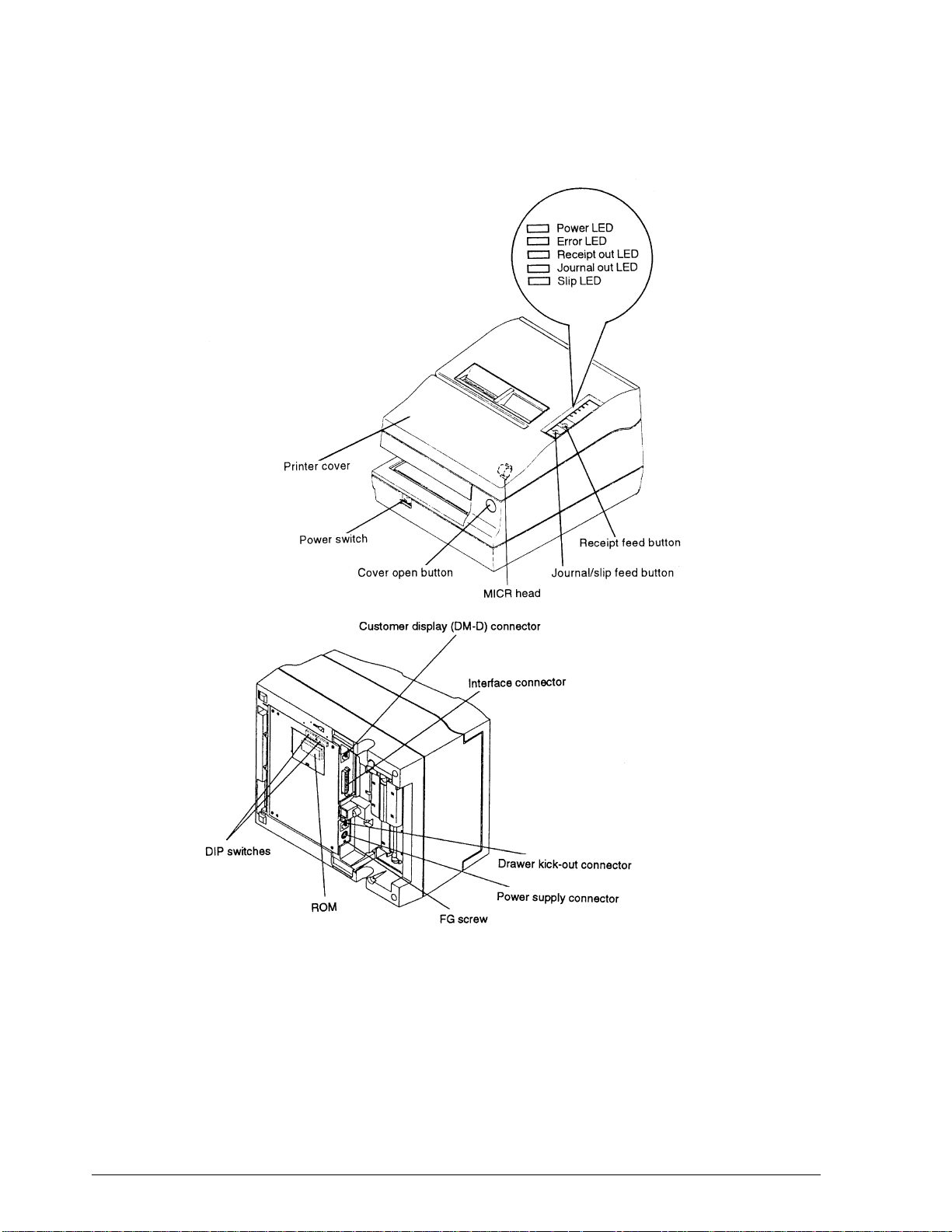
Figure 1-1. TM-U950 Appearance
1-2 Features and General Specifications Rev. A
Page 14
CONFIDENTIAL
General Specifications
Printing Specifications
Operation principle
Serial impact dot-matrix printer
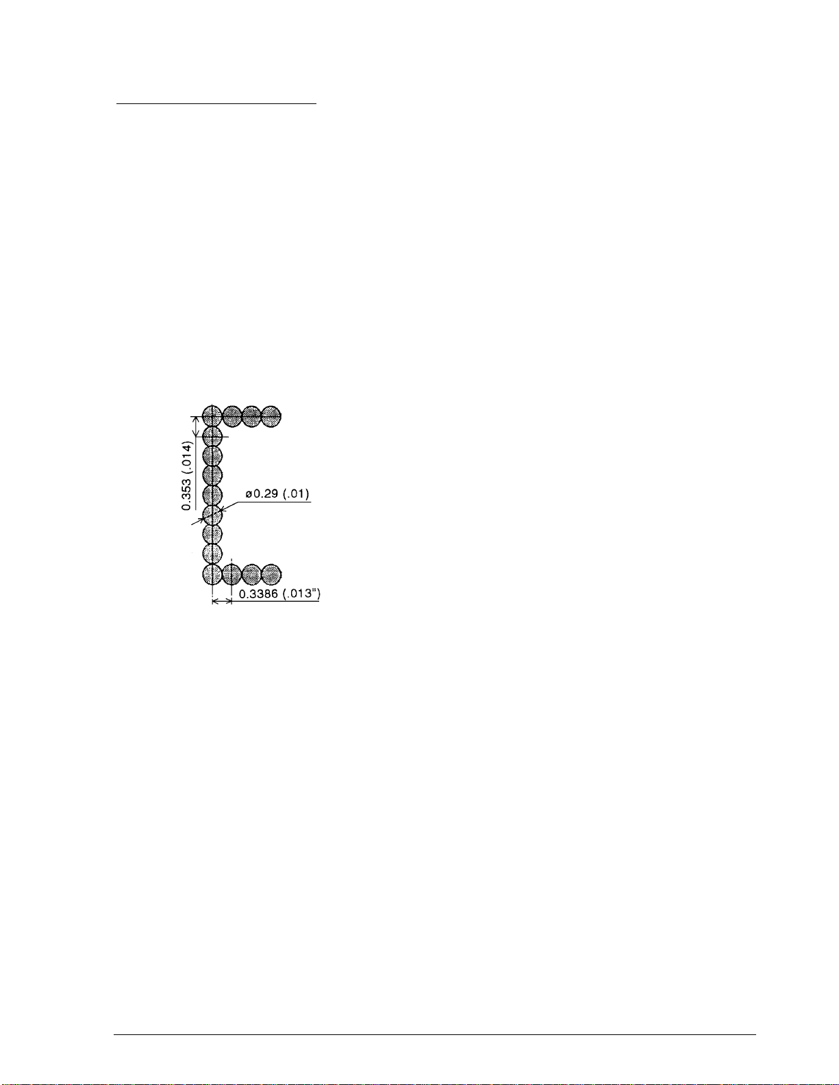
Print head wire layout
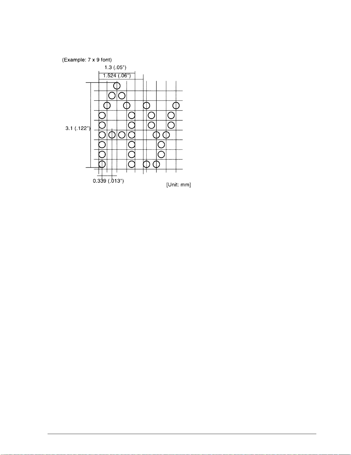
Serial 9-pin
Dot pitch
0.353 mm (1/72”)
Dot wire diameter
0.29 mm (.01”)
TM-U950/U950P Technical Manual
Figure 1-2. Dot Configuration
Print direction
Bidirectional logic seek
Print width (printable area)
Paper roll: 61.1 mm (2.41”)
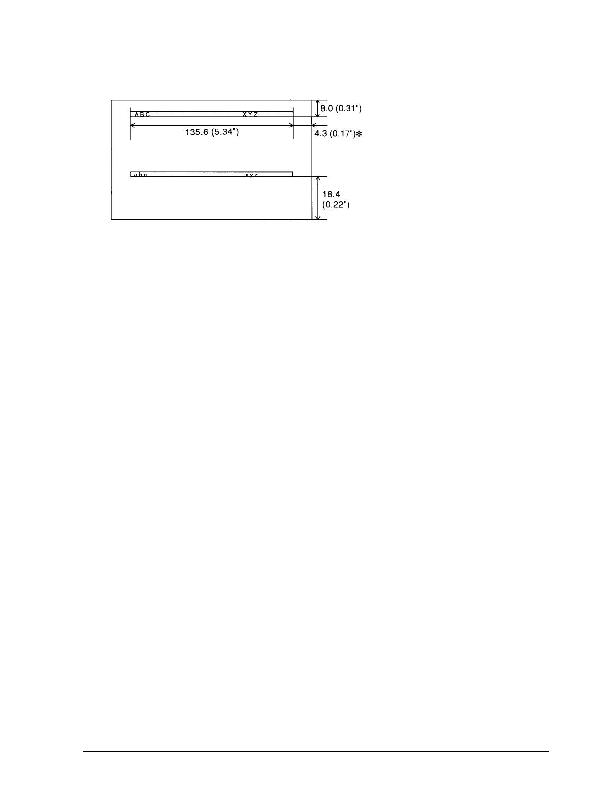
Slip paper: 135.6 mm (5.34”)
Paper feed pitch
4.233 mm (1/6”) (default setting) adjustable (by commands) in 1/144-inch steps
Paper feed principle
Friction feed
Paper feed rate
Approx. 3.4 IPS (continuous paper); 60.3 ms per line (1/6-inch paper feed)
Rev. A Features and General Specifications 1-3
Page 15
CONFIDENTIAL
Printing format
See CPI in Table 1-2.
Character spacing
See Table 1-2.
Total dot count
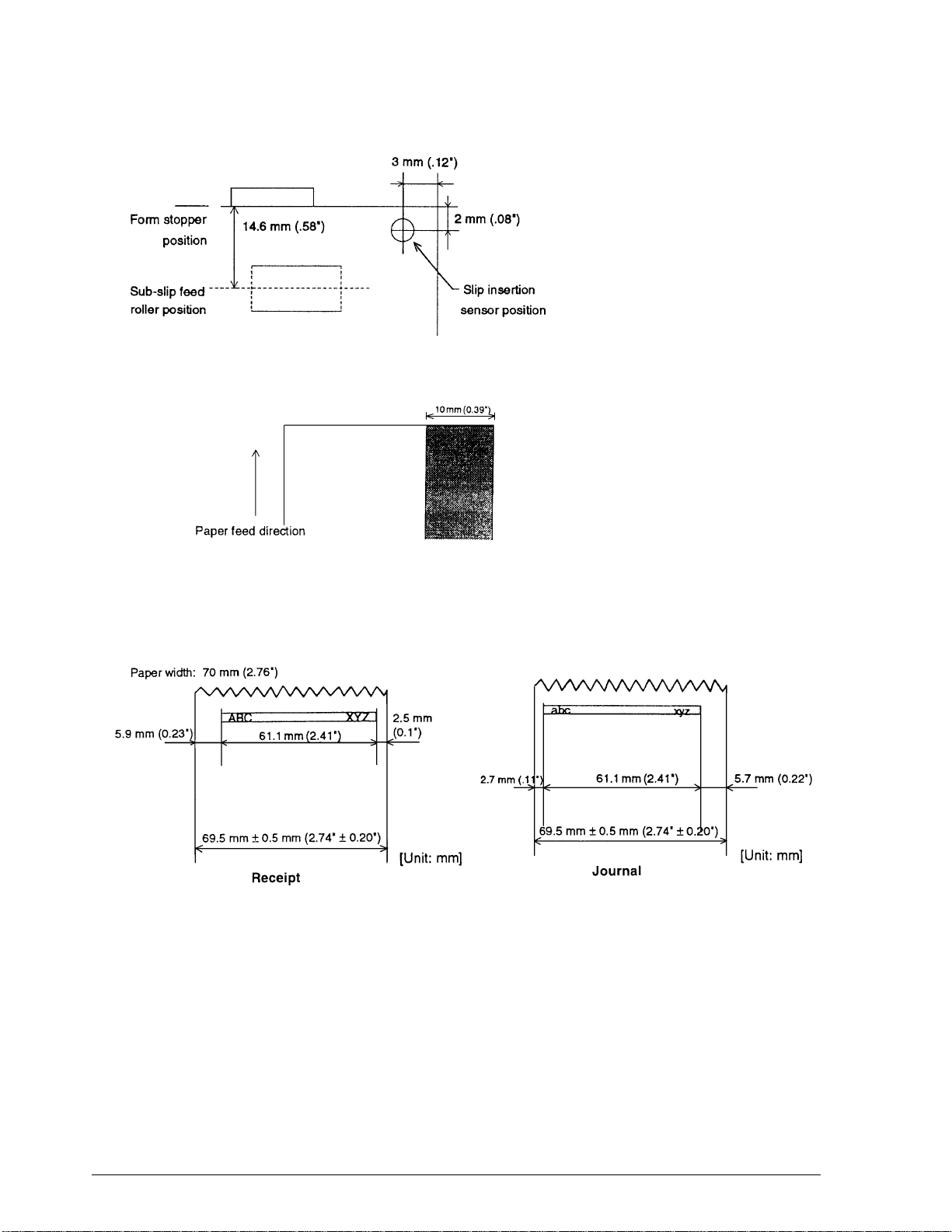
70 mm paper roll (2.76”): 180 dots (360 positions) per line
Slip paper: 400 dots (800 positions) per line
Printing speed
See Table 1-2.
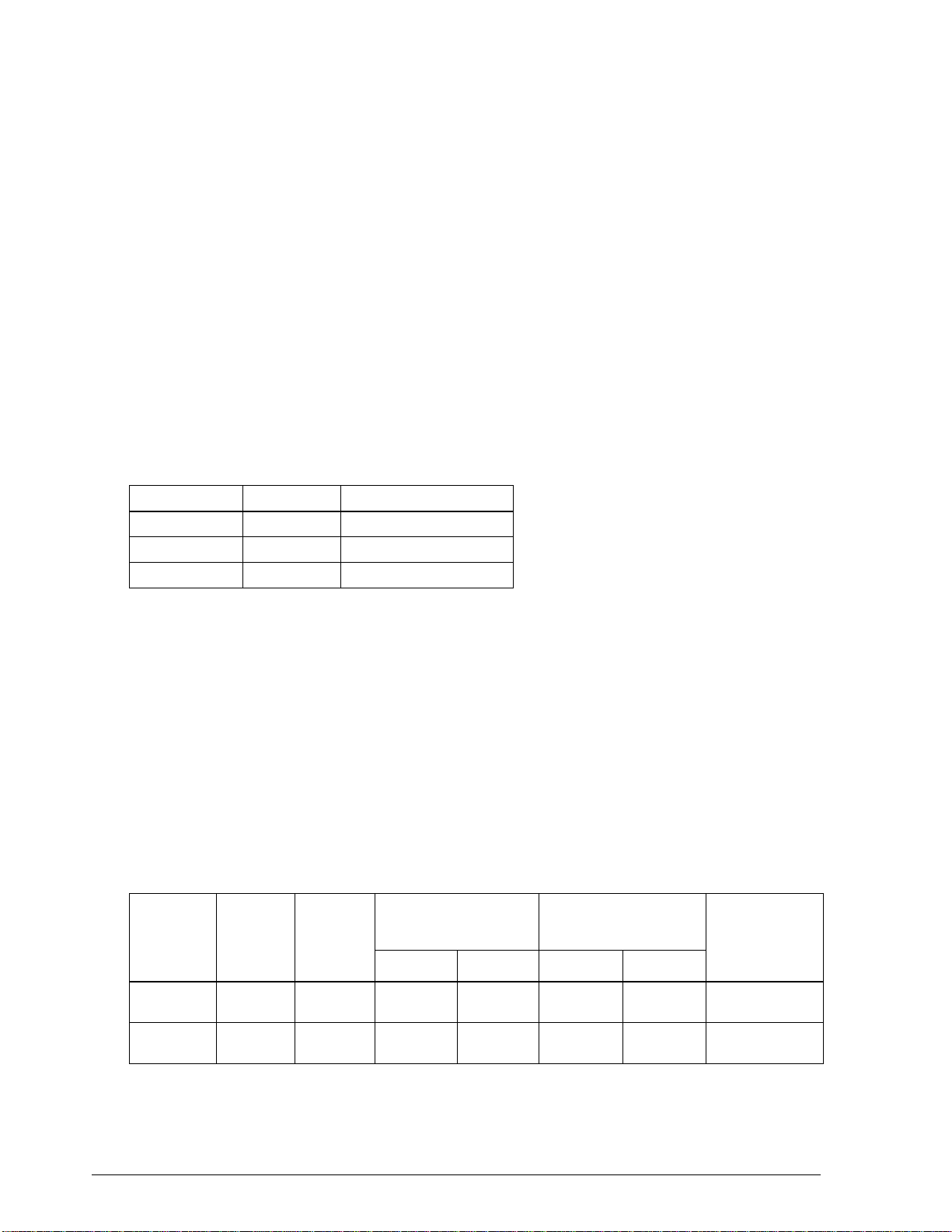
As shown in the table below, the TM-U950 has three printing modes, which differ in printing
speed and head power time (impact).
Table 1-1. Printing Operation Mode
Operation mode Printing speed Head power time (impact)
Standard High Standard
Copy Low Copy
Low-speed Low Standard
Character Specifications
Character set
Alphanumeric: 95
International: 32
Extended graphics: 128 x 8 pages
Character matrix
(Alphanumeric, international, extended graphics)
7 x 9 (spacing: 2 half-dots)
0 x 9 (spacing: 3 half-dots)
Larger spacing can be set by using ESC SP.
Table 1-2. CPI, CPS, CPL, Character Size
CG Mode
(Horizontal
dots x
vertical
dots)
9 x 9 3 dots 12.5 233 200 30 66
7 x 9 2 dots 16.7 311 267 40 88
Character
Spacing
(half dots)
Characters
Per Inch
(CPI)
Characters Per Second
(CPS) (Carriage moving
speed)
High speed Low speed Paper roll Slip paper
Characters Per Line (CPL)
Character Size
Width x Height
1.6 mm x 3.1 mm
(0.6” x .12”)
1.3 mm x 3.1 mm
(0.5” x .12”)
1-4 Features and General Specifications Rev. A
Page 16
CONFIDENTIAL
TM-U950/U950P Technical Manual
Figure 1-3. Character Size
Paper Specifications
Paper type
❏ Paper roll
Wood-free paper (single layer only)
❏ Slip paper
Plain paper
Carbon copy paper
Pressure-sensitive paper
Paper dimensions
❏ Paper roll
Paper width: 69.5 + 0.5 mm (2.74 + 0.02”)
Maximum diameter: 83 mm (3.27”)
Paper thickness: 0.06 to 0.09 mm (.002 to .004”)
Paper weight: 52.3 to 64 g/m
(45 to 55 kg/1000 sheets; 788 x 1091 mm)
(20.41 to 24.94 lbs/1000 sheets; 31.02 x 42.95”)
Core diameter: 10 mm (0.39”) or more
Rev. A Features and General Specifications 1-5
2
(13.9 to 171 lbs)
Page 17

CONFIDENTIAL
❏ Slip paper
Dimensions: 70 x 70 to 210 x 297 mm (W x H)
Thickness: 0.09 to 0.36 mm (.004 to .014”)
Temperature and copying capability
As copying capability is influenced by the ambient temperature, printing must be performed
under the conditions descri bed in Table 1-3.
Table 1-3. Relationship Between Ambient Temperature and Number of Copies
Number of Copies Ambient Temperature
Original + 4 copies approx. 20
Original + 1 to 3 copies 5
Paper thickness and copying capability
(2.76 x 2.76 to 8.27 x 11.69”)
to 40°C (68° to 104°F)
°
to 40°C (41° to 104°F)
°
❏ Plain paper (single sheet): 0.09 to 0.2 mm
(.0035 to .0079”)
❏ Carbon copy paper (original + 4 copies)
Backing paper 0.06 to 0.15 mm (.002 to .006”)
Copy paper and original paper 0.04 to 0.07 mm (.0016 to .003”)
Carbon paper Approx. 0.035 mm (.001”)
Total thickness 0.30 mm (.012”) or less (1 to 1 + 3)
0.36 mm (.014”) or less (1 + 4)
❏ Pressure-sensitive paper (original + 4 copies)
Backing paper 0.06 to 0.15 mm (.002 to .006”)
Copy paper and original paper 0.06 to 0.075 mm (.002 to .003”)
Total thickness 0.24 mm (.009”) or less (1 to 1 + 3)
0.30 mm (.012”) or less (1 + 4)
Note:
When using multi-ply paper that consists of an original and three copies, be sure to print with a 9 x 9 font.
If a 7 x 9 font is used, some characters on some of the copies may not be readable.
Check paper (only when the printer is used with the MICR reader)
Paper type: Normal paper
Total thickness: 0.09 to 0.2 mm (.0035 to .0079”)
1-6 Features and General Specifications Rev. A
Page 18
CONFIDENTIAL
Size: 68 to 102 mm x 152 to 210 mm
Weight: 70 to 90 kg paper
Notes on setting the print operation mode
❏ The GS E command sets print mode (printing speed and print head energizing time).
❏ When the power is turned on, normal mode is selected as the default. The printer
automatically switches from normal mode to copy mode when slip is selected by ESC c 0.
Notes on slip paper
❏ The slip paper must be flat, without curls or wrinkles, especially at the top edges. Otherwise,
the paper may rub against the ribbon and become dirty.
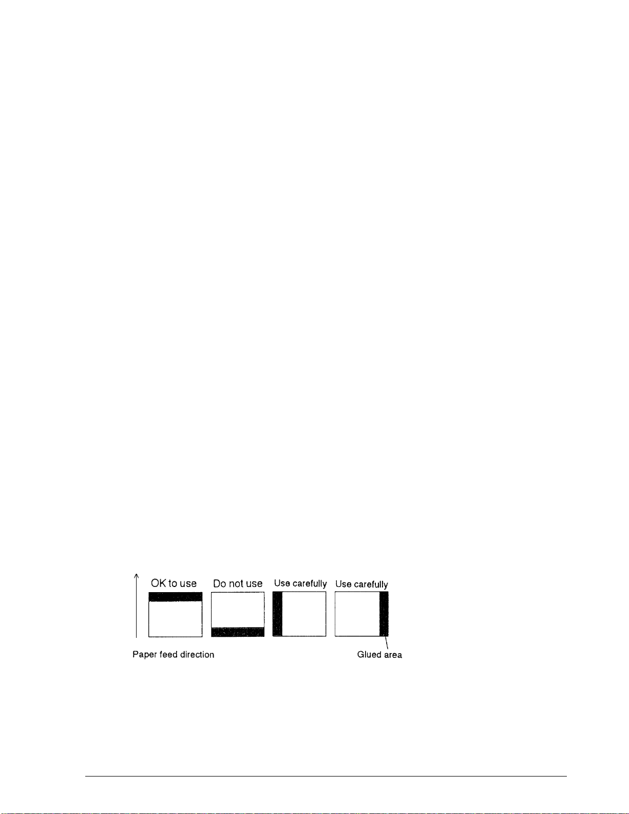
❏ There must be no glue on the bottom edge of slip paper. It is desirable for the glue to be on
the top edge. Choose slip paper carefully when the glue is on the right or left edge, since
paper feeding and insertion are affected by gluing conditions (e.g., glue quality, method,
and length) and glue location (see Figure 1-4). Be especially careful when slip paper is wide
and has the glue on the right or left edge, since meandering may occur.
TM-U950/U950P Technical Manual
(2.68 to 4.02” x 2.98 to 8.27”)
❏ Since the slip insertion sensor uses a photo sensor, paper that has holes at the sensor
position, or is translucent, must not be used (see Figure 1-5).
❏ Since the slip ejection sensor uses a reflective photo sensor, paper that has holes or dark
portions with low reflection (less than 40% reflection) at the sensor position must not be
used (see Figure 1-6).
❏ Be sure to perfor m slip printing with a paper roll loaded to avoid incorrect paper feeding
due to paper jams.
❏ Use thinner paper (N30 or equivalent) between the top and bottom sheets of multi-ply
paper. If thick paper is used, the copy capab ility is lowered.
Notes on using personal check paper (for printers with an MICR reader)
❏ The personal checks must be flat, without curls, folds, or wrinkles (especially at the edges).
Otherwise, the check may rub against the ribbon and become ink-stained.
Figure 1-4. Slip Paper Glued Area
Rev. A Features and General Specifications 1-7
Page 19
CONFIDENTIAL
Figure 1-5. Slip Insertion Sensor Position
Figure 1-6. Paper Holes and Low Reflection Prohibited Area
Print area
❏ Paper roll
Figure 1-7. Paper Roll Print Area
1-8 Features and General Specifications Rev. A
Page 20
CONFIDENTIAL
❏ Slip paper
Figure 1-8. Slip Paper Print Area
*Note
When the printer uses an MICR reader, this width is 5.0mm (0.20”).
Paper Roll Feed Mechanism
TM-U950/U950P Technical Manual
Feed principle
Drop-in loading
Paper roll near-end detection
Separate sensors for receipt paper and journal paper.
Journal Paper Take-up Mechanism
Automatic take-up by journal paper f eed motor.
Auto-cutter
Auto-cutter is installed only on receipt side, for full and partial cuts.
Electrical Specifications
Printer operation voltage (using supplied AC adapter)
+24 V DC ± 10%
Ripple voltage: 300 mVpp or less (only when the printer is used with the MICR reader)
Current consumption
❏ During printing
Average approx. 1.8 A
(R/J, α - N, 40-character printing)
Peak approx. 8 A
❏ During slip paper feed to printing position:
Average approx. 0.3 A (for approx. 1.4s)
Rev. A Features and General Specifications 1-9
Page 21

CONFIDENTIAL
❏ During standby
Average approx. 0.3 A
❏ Operating MICR reader
(when the printer used with the MICR reader)
Mean - approximately 2.3 A
(Approximately 1.4 seconds)
Stamp
Stamp mechanism is available as a factory option for the receipt side.
Recommended stamp: Fuji Copian CSP-2042C
Recommended ink: Fuji Copian Super Ink
Print area: 42 x 20 mm (1.65 x 0.79”)
(W x H)
Dimensions of stamp pad: See Figure 1-9.
Dimensions of stamp set: See Figure 1-10.
Figure 1-9. Stamp Pad Dimensions Figure 1-10. Stamp Set Dimensions
Ink Ribbon
Ribbon cassette
ERC-31 (P)
ERC-31 (B)
[Unit: mm]
Color
Purple: ERC-31 (P)
Black: ERC-31 (B)
Ribbon life (18 dots per character)
Figure 1-11. Ribbon Cassette Dimensions
7,000,000 characters
1-10 Features and General Specifications Rev. A
Page 22

CONFIDENTIAL
Dimensions, Weight, Finish
Dimensions
251 x 298 x 194.5 mm (9.88 x 11.73 x 7.66”) (W x D x H)
Weight
Approx. 5.6 kg (12.3 lbs)
Color
EPSON Standard Gray
Environmental Specifications
Temperature
Operation: 5° to 40°C (41° to 104°F)
Storage: -10° to +50°C (14° to 122°F) (except ribbon)
TM-U950/U950P Technical Manual
Humidity
Operation: 30 to 80% (non-condensing; limit above 30°C: 30°C, 80%)
Storage: 30 to 90% (non-condensing; except ribbon)
Vibration resistance (in standard EPSON packing)
Frequency: 5 to 55 Hz
Acceleration: 2 G
Sweep: 5 minutes (one way)
Time: 1 h
Directions: X, Y, Z
No visible external or internal problems or operation failure after the above vibration test.
Shock resistance (in standard EPSON packing)
❏ With packing
Drop height: 50 cm (19.69”)
Angle: 1 angle, 3 surfaces, 6 sides
No visible external or internal problems or operation failure after the above drop test.
❏ Without packing
Drop height: 5 cm (1.97”)
Angle: 4 sides, one-point support
No damage when dropped while printer is off.
Rev. A Features and General Specifications 1-11
Page 23

CONFIDENTIAL
Noise
63 dB (operating, measured in ANSI bystander position; printing on receipt and journal paper
roll)
Reliability
Mechanics
MCBF 5,000,000 lines (auto-cutter and stamp once every 15 lines)
Life expectancy 7,500,000 lines (The printer’s life is considered over when the
Life expectancy of print head 150,000,000 characters (average 2 dot/wire/1 character)
MICR reader mechanism (only when the printer is used with the MICR reader):
MCBF: 160,000 passes
printer cannot function due to worn-out main parts such as
motor, solenoids, frames, and shafts.)
Life: 240,000 passes
1 pass: reading characters to printing endorsements on a
U.S. personal check (152 mm (5.98”) long)
The MICR reader is defined to have reached the end of its
life when it cannot function proper ly because of wearing out
of the main parts (magnetic head, head holding roller, etc).
Certifications
Japan: EMI: VCCI Class 1
North America: EMI: FCC Class 1
Safety standards: UL1950-2TH-D3
C-UL
Europe: CE marking (printer with MICR reader under application)
EN55022
EN50082-1
EN45501 (except when connected to IM)
Safety standard: TÜV
1-12 Features and General Specifications Rev. A
Page 24
CONFIDENTIAL
Hardware Configuration
Main Unit Configuration
Printer mechanism
TM-U950/U950P Technical Manual
Figure 1-12. TM-U950 Printer Mechanism Main Unit Configuration
Electrical circuit and unit on cases
Figure 1-13. TM-U950 Electrical Circuit and Unit on Cases Main Unit Configuration
Rev. A Features and General Specifications 1-13
Page 25

CONFIDENTIAL
Main Unit Specifications
Paper feed motors
Receipt and journal paper feeding is performed by dedicated feed motors. Slip paper feeding is
performed by using the journal paper feed motor and a journal/slip switching solenoid.
Motor type
4-phase, 48-pole PM type stepping motor
Drive voltage
24 V DC + 10% (including voltage drop caused by drive transistor)
Winding resistance
Journal paper fe ed motor 35 Ω ± 7% at 25°C (77°F), per phase
Receipt paper feed motor: 42 Ω ± 7% at 25°C (77°F), per phase
Current consumption (per motor)
❏ Journal paper fee d motor
Peak current: 1.94A in worst case
Average current: 615 mA at rated speed; 25°C (77°F), 24 V DC, 500 pps
930 mA max. in worst case
Hold current 92.5+42.5 mA per phase at normal hold, 25°C (77°F)
❏ Receipt paper feed motor
Peak current: 1.5 A in worst case
Average current: 510 mA at rated speed; 25°C (77°F), 24 V DC, 500 pps
770 mA max. in worst case
Hold current: Approx. 130 ± 50 mA per phase at normal hold, 25
Drive frequency
500 pps (minimum pulse interval 2.00 ms)
Drive principle
Constant voltage drive, 2-2 phase induction
C (77°F)
°
Carriage motor
Motor type
4-phase, 48-pole PM type stepping motor
1-14 Features and General Specifications Rev. A
Page 26

CONFIDENTIAL
Drive voltage
24 V DC ± 10% (including voltage drop caused by drive transistor)
Winding resistance
9 Ω ± 7% at 25°C (77°F), per phase
Current consumption (per motor)
Peak current: 1.5 A in worst case
Average current: 550 mA at rated speed
Hold current: 150 mA± 8% per phase
Drive frequency
Standard mode: 1400 pps (pulse interval 714 µs)
Copy mode: 1200 pps (pulse interval 834 µs)
Drive principle
Constant-current chopper drive, 2-2 phase induction
TM-U950/U950P Technical Manual
Carriage feed pitch
0.3386 mm (1/75”) per pulse
Print head unit (print solenoids)
Number of solenoids: 9
Drive voltage: 24 V DC ± 10% (including voltage drop caused by drive
transistor)
DC resistance: 6.65 Ω ± 4% at 25°C (77°F)
Near-end sensors (journal, receipt)
A sensor is provided for the receipt and journal paper roll respectively. The sensors check the
diameter of each roll and activate the near-end alarm when the diameter falls below a userdetermined value.
Sensor type: Microswitch
Voltage: 5 V DC ± 5%
Output level: Low when near-end is detected
Paper roll sensors (journal, receipt) (*)
A sensor is provided in the paper path (receipt and journal side, respectively) of the printer
mechanism. These sensors check for the presence of paper, and accordingly control loading of
the paper roll.
Sensor type: Microswitch
Switch rating: 10 to 100 mA, 5 V DC (resistive load)
Contact condition: On when paper is present
(*) If the paper roll sensor detects the “no paper” condition while the cover is open, semi-
automatic loading can be performed by inserting the paper roll into the paper path.
Rev. A Features and General Specifications 1-15
Page 27

CONFIDENTIAL
Slip paper insert sensor
This sensor is located in the slip paper loading path to detect the insertion of slip paper.
Sensor type: Photosensor
Voltage: 5 V DC ± 5%
Input current: Approx. 20 mA
Output level: High when slip paper is detected
Slip paper eject sensor
This sensor is located in the slip paper eject pa th to dete ct eje c ti on of slip pape r. If ej ecti on is not
detected, the printer does not proceed to the next step.
Sensor type: Photosensor
Voltage: 5 V DC ± 5%
Cover open sensor (*)
This sensor detects the condition of the printer cover. If the cover is open, the printer
automatically goes off-line after the current printing operation and the carriage returns to the
home position at slow speed. The printer goes back on-line when the cover is closed.
Sensor type: Photosensor
Voltage: 5 V DC ± 5%
Input curr ent: 10 m A
Output level: High when cover open is detected
(*) If the paper roll sensor detects the “no paper” condition while the cover is open, semi-
automatic loading can be performed by inserting the paper roll into the paper path.
Auto-cutter sensor
Sensor type: Mechanical contact sensor
Voltage: 5 V DC ± 5%
Current rating: 0.1 to 0.5 mA
Home position sensor
This sensor detects the carriage initial position (on the receipt paper side) and the carriage
abnormal operation.
Sensor type: Photosensor
Voltage: 5 V DC ± 5%
Output level: High when the carriage home position is detected
Carriage sensor
This sensor outputs signal synchronized with the carriage operation, and detects whether the
carriage operation is abnormal.
Sensor type: Photosensor
Voltage: 5 V DC ± 5%
Output level: High when sensor plate is detected
1-16 Features and General Specifications Rev. A
Page 28

CONFIDENTIAL
MICR Reader (when the printer is used with the MICR reader)
(Not available for the TM-U950P)
Available fonts: E-13B, CMC7
Recognition rating: 98% or more (at 25
Recognition rating is defined as follows:
Recognition rating (%) =
Check paper used for test is EPSON standard check paper. Checks must be flat, without curls,
folds, or wrinkles.
Connectors
All connectors are located on the rear panel of the printer. (Refer to Figure 1-1.)
TM-U950/U950P Technical Manual
C)
°
Total number of checks - (number of sheets misread
and those not identified)
Total number of checks
× 100
Connector panels
14 25
8
1
1
Customer display
(DM-D) connector
Interface
connector
13
1
Drawer kick-
out connector
Figure 1-14. Rear Panel Connectors
6
2
1
3
Power
connector
Interface connector Drawer kickout Power connector
Interface
See the Interface section in this chapter.
Power supply connector
This connector is for the AC adapter.
Connector type: TCS7960-53-2010 (Hoshiden) or equivalent
Table 1-4. Power Supply Pin Assignment
Pin number Function
1 24 VDC
2 Signal ground
3NC
Shell Frame ground
connector
TM-U950PTM-U950
Note:
Be sure to ground the printer via the frame ground terminal on the metal strip on the rear panel.
Rev. A Features and General Specifications 1-17
Page 29
CONFIDENTIAL
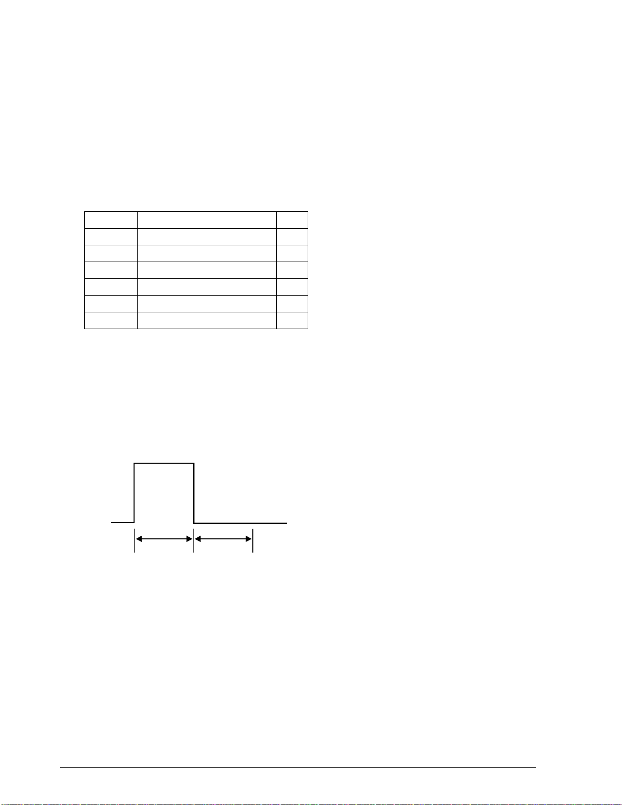
Drawer kick-out connector (modular connector)
Pulse specified by ESC p command is ou tput to this connect or. The host can confirm the st atus of
the input signal by using the DLE EOT, ESC u, GR r, or GS a (ASB) commands.
Connector type:
Printer side 52065-6615 (Molex) or equivalent
User side 6-position 6-contact (RJ12 telephone jack)
Table 1-5. Drawer Kick-out Connector Pin Assignment
Pin number Signal name I/O
1Frame ground —
2 Drawer kick-out drive signal 1 (*1) O
3 Drawer open/close signal (*2) I
4 + 24 V —
5 Drawer kick-out drive signal 2 (*1) O
6 Signal ground —
(*1) Drawer kick-out drive signal
The signal specified by the ESC p command is output from pins 2 and 5 of the connector.
Output voltage: Approx. 24 V
Output current: 1 A max.
Output waveform: The waveform of the signal at pins 2 and 5 is shown in
Figure 1-15. (The ON time n1 and OFF time n2 are
determined by the ESC p command.)
n1 x 10ms n2 x 10ms
Figure 1-15. Drawer Kick-out Drive Signal Timing
(*2) Drawer open/close signal
The host computer can check the drawer open/close status with the DLE EOT, ESC u, GR r, or
GS a (ASB) commands.
Input signal level (connector pin 3)
Low = 0 to 0.8 V
High = 2 to 5 V
1-18 Features and General Specifications Rev. A
Page 30

CONFIDENTIAL
Notes
❏
Use a shielded cable for the drawer connection.
❏
It is not possible to drive two drawers at the same time.
❏
Use a solenoid rated for at least 24 Ω as the drawer kick-out solenoid. Otherwise, excessive current
may damage the solenoid.
❏
The drawer must be powered from the printer (connector pin 4).
❏
Do not drive the drawer continuously.
Customer display connector (not supported on the TM-U950P)
This connector is for Epson customer display (DM-D series). Do not connect other customer
displays.
Connector type: Receptacle 52065-8845 (Molex) or equivalent
TM-U950/U950P Technical Manual
Table 1-6. Customer Display Connector Pin Assignment
Pin number Signal name I/O
1Frame ground—
2NC —
3TXD O
4DTR O
5DSRI
6 Signal ground —
7 +24V DC —
8 Power ground —
Interface
Serial interface
Data transfer principle Serial (RS-232 interface)
Synchronization Asynchronous
Handshake (*) DTR/DSR or XON/XOFF
Signal level
MARK: -3 to -15 V (logical “1”/OFF)
SPACE: +3 to +15 V (logical “0”/ON)
(Voltage measured at connector, referenced to SG)
Baud rate (*) 1200, 2400, 4800, 9600 bps
Word length (*) 7 or 8 bit
Rev. A Features and General Specifications 1-19
Page 31

CONFIDENTIAL
Parity (*) None, even, odd
Number of stop bits 1 or more
Connector type D-SUB 25 female or equivalent
(*)Can be set with DIP switches on the bottom of the unit (See Tables 1-9 and 1-10.)
On-line/off-line switching
This printer has no on-line/off-line switch. It automatic ally goes off-line in the following cases:
❏ During self-test.
❏ When the cover is open.
❏ When the paper feed button (receipt or journal/slip) is used to advance the paper.
❏ When printing has stopped due to no paper (“no paper” condition selected with ESC c 4).
❏ During the interval between power-on (including reset using the interface) and the end of
the initialization sequence, until data can be received.
❏ When an error has occurred
❏ During the macro execution switch waiting status.
Table 1-7. Interface Connector Specifications and Functions
Pin number Signal name I/O Function
1FG—Frame ground
2 TXD O Transmit data
3 RXD I Receive data
4RTSO
6DSRI
7SG—Signal ground
DIP SW1-6 off: Same as DTR signal (Pin20)
DIP SW1-6 on: Logical product of DTR signals of DM-D and TM (if both are
SPACE, the printer can receive data.
Indicates whether the host is ready to receive data. SPACE indicates
“ready,” and MARK indicates “not ready.” If DTR/DSR control is used, the
printer checks this signal before sending data (except when sending
data by GS ENG, DLE ENQ, GS a). If XON/OFF control is used, this signal is
not checked.This signal can be used to reset the printer according the
DIP switch settings. The printer is reset when the signal is MARK with more
than 1 ms pulse width.
1-20 Features and General Specifications Rev. A
Page 32

CONFIDENTIAL
Table 1-7. Interface Connector Specifications and Functions
Pin number Signal name I/O Function
20 DTR O
25 INIT I
Table 1-7a. Pin 20 Information
Printer status
During the interval between
power-on (reset using interface)
and the time when the printer is
ready to receive data.
During the self-test BUSY BUSY
When the cover is open. — BUSY
During paper feeding with the
paper feed button.
When the printing has stopped
due to a paper-end.
When an error has occurred. — BUSY
When the receive buffer becomes
full (*1).
TM-U950/U950P Technical Manual
1) When DTR/DSR control is selected, this signal indicates whether the
printer is busy. MARK indicates busy and SPACE indicates not busy. The
busy condition is changed using DIP switch 5 of the bank 2 as shown in
Table 1-7a.
2) When XON/OFF control is selected, the signal indicates whether the
printer is correctly connected and is ready to receive data. SPACE
indicates “ready”. The signal is always SPACE except in the following two
cases:
(o) During the interval between power-on and the time when the printer
is ready to receive data.
(o) During the self-test.
Changing the DIP switch setting enables this signal to be used as a reset
signal for the printer. The printer is reset when the signal remains SPACE for
1 ms or more.
DIP SW 2-5 status
ON OFF
BUSY BUSY
—BUSY
—BUSY
BUSY BUSY
(*1) The “buffer full” conditio n in this ca se starts when remaining buffer space fall s to 16 bytes or
less and ends when it becomes 26 bytes or more. The printer ignores the data when the
remaining space in the receive bu ffer is 0 bytes.
Note
Pins 8 - 19 and 21 - 24 are not used.
Rev. A Features and General Specifications 1-21
Page 33

CONFIDENTIAL
XON/XOFF control
When XON/XOFF control is selected, the XON and XOFF output timing is as described below.
(XON code: 11H; XOFF code: 13H) Transmit timi ng differ s depending on the DIP swit ch 5 of t he
bank 2.
Table 1.8. XON/XOFF Transmit Timing
XON transmission
XOFF transmission
Printer status
When the printer goes on-line after the power-on or reset with
interface.
When the receive buffer is released from the buffer full state. Transmit Transmit
When the printer changes to on-line. (*1) — Transmit
When the printer recovers from an error by the DLE ENQ 1 or DLE
ENQ 2.
When receive buffer becomes full. Transmit Transmit
When the printer changes to off-line. (*2) — Transmit
DIP SW 2-5 status
ON OFF
Transmit Transmit
—Transmit
(*1) XON is not transmitted when the receive buffer is full.
(*2) XOFF is not transmitted when the receive buffer is full.
Notes on setting DIP switch 2-5 on
❏
The printer stops printing mechanism operation but does not go off-line when an error has occurred,
printing stops due to a paper-end, or paper is fed using the paper feed button.
❏
When setting DIP SW 2-5 on to enable handshaking with the host computer, be sure to check the
printer status by the GS a command and automatic status transmission function. In this setting, the
default values of n for GS a is 2, and the printer automatically transmits the changes in on-line/offline.
❏
When using DLE EOT, DLE ENQ, and GS ENQ, be sure that the receive buffer does not become full.
a) When using a host that cannot transmit data when the printer is busy:
If an error has occurred, DLE EOT, DLE ENQ, and GS ENQ cannot be used when the printer is
busy due to receive buffer-full.
b) When using a host that can transmit data when the printer is busy:
When the receive buffer becomes full while transmitting data, DLE EOT, DLE ENQ, or GS ENQ
using between the bit image data is processed as bit image data. The data transmitted when the
receive buffer is full may be lost.
1-22 Features and General Specifications Rev. A
Page 34

CONFIDENTIAL
The following illustrates an example serial interface connection:
TM-U950/U950P Technical Manual
Host (DTE example 8251)
TXD
DSR
CTS
RXD
DTR
FG
SG
When connected to a DCE-type device, data should not be
sent non-stop (without handshake).
DTE = Data Terminal Equipment
DCE = Data Circuit Terminating Equipment
Printer
RXD
DTR
RTS
TXD
DSR
FG
SG
Figure 1-16. Serial Interface Connection Example
Parallel interface
(Bidirectional parallel interface in accordance with the IEEE 1284 nib ble/byte modes).
Copyright © 1994 by the Institute of Electrical and Electronic Engineers, Inc.
Compatibility mode
(Data transmission from host to printer: Centronics compatible)
Data transmission: 8-bit parallel
Synchronization: Externally supplied nStrobe signals
Handshaking: nAck and Busy signals
Signal levels: TTL compa tible
Connector: 57RE-40360-830E(DDK) or equivalent (IEEE 1284 Type B)
Reverse mode
(Data Transmission from printer to host)
The STATUS data transmission from the printer to the host is accomplished in the Nibble or
Byte mode.
This mode allows data tr ansmission from the asynchronous prin ter under the control of the
host. Data transmission in the Nibble mode are made via the existing control lines in units of
four bits (Nibble). In the Byte mode, data transmission is accomplished by making the 8-bits
data lines bidirectional.
Neither mode can operate at the same time as the compatibility mode, so switching is always
required.
The 1284 Nibble/Byte modes may be subject to change without notice.
Rev. A Features and General Specifications 1-23
Page 35

CONFIDENTIAL
TM-U950P printer status and signals
Pin No. Source Compatibility mode Nibble mode Byte mode
1 Host nStrobe HostClk HostClk
2 Host/Printer Data0 (LSB) Data0 (LSB) Data0 (LSB)
3 Host/Printer Data1 Data1 Data1
4 Host/Printer Data2 Data2 Data2
5 Host/Printer Data3 Data3 Data3
6 Host/Printer Data4 Data4 Data4
7 Host/Printer Data5 Data5 Data5
8 Host/Printer Data6 Data6 Data6
9 Host/Printer Data7 (MSB) Data7 (MSB) Data7 (MSB)
10 Printer nAck PtrClk PtrClk
11 Printer Busy PtrBusy/Data3, 7 PtrBusy
12 Printer PError
13 Printer Select Xflag/Data1, 5 Xflag
14 Host nAutoFd HostBusy HostBusy
15 NC ND ND
16 GND GND GND
17 FG FG FG
18 Printer Logic-H Logic-H Logic-H
19 to 30 GND GND GND
31 Host nInit nInit nInit
32 Printer nFault nDataAvail/Data0, 4 nDataAvail
33 GND ND ND
34 Printer DK_STATUS ND ND
35 Printer +5V ND ND
36 Host nSelectIn 1284-Active 1284-Active
AckDataReq/
Data2, 6
AckDataReq
NC: Not connected, ND: Not defined
Notes:
❏ A prefix "n" to signal names refers to low active signals.
❏ If the host does not have any one of the signal lines listed above, two-way communication
fails.
❏ For interfacing, signal lines should use twisted pair cables with the ret urn sides connected to
the signal ground level.
1-24 Features and General Specifications Rev. A
Page 36

CONFIDENTIAL
❏ Interfacing conditions should be all based on th e TTL level. In addition, both the rise time
and fall time of each signal must be 0.5 µs or less.
❏ Data transmission should not ignore the signal nAck or Busy. An attempt to transmit data
with either signal, nAck or Busy, ignored can cause lost data. (Data transmission to the
printer should be made after verifying the nAck signal or while the Busy signal is low.)
❏ Interface cables should be as short as possible.
Precautions on receiving status from the printer
The printer status transmi ssion is available by using the both-way communi cati on fa cil i ty in t he
Nibble/Byte mode in accordance with the IEEE 1284 mode.
The following precautions must be taken for receiving the status from the printer.
❏ The allowable capacity of the printer’s internal buffer is 100 bytes. Status signals exceeding
this capacity will be discarded. To prevent possible loss of status data, the host should
always be ready for data reception (reverse mode).
TM-U950/U950P Technical Manual
❏ When ASB is used, the host should be in the wait state for data reception (reverse idle
mode). When this state is not available, the host should enter the reverse mode to always
monitor the presence of data.
❏ When ASB is used, preference should be given to the ASB status for transmission over the
other status signals. Any accumulated ASB status signals left for transmission from the last
to the newest ASB status transmission should be transmitted together at one time as one
ASB status showing the change has been made, followed by the latest ASB status.
Example: In the normal (wait) state, the ASB status is configured as follows:
1st status 2nd status 3rd status 4th status
0000 0000 0000 0000 0000 0000 0000 0000
When the following sequence of operations is performed, near end detection, cover open, cover
closed, the following pieces of data are accumulated.
1st status 2nd status 3rd status 4th status
1 0000 0000 0000 0000 0000 0011 0000 0000 Near end detection
2 0010 1000 0000 0000 0000 0011 0000 0000 Cover open
3 0000 0000 0000 0000 0000 0011 0000 0000 Cover closed
When the ASB status is received following this, a total of 8 bytes of ASB will be transmitted as
follows.
1st status 2nd status 3rd status 4th status
Accumulated ASB (1+2+3) 0010 1000 0000 0000 0000 0011 0000 0000
+ 1st status 2nd status 3rd status 4th status
The latest ASB (3) 0000 0000 0000 0000 0000 0011 0000 0000
Rev. A Features and General Specifications 1-25
Page 37

CONFIDENTIAL
Switching between on-line and off-line
The TM-U950P printer does not have an on-line/off-line button. The printer goes off-line in the
following conditions:
❏ Between the time when the power is turned on (including reset using the interface) and
when the printer is ready to receive data.
❏ During the self-test.
❏ When the cover is open.
❏ During paper feeding using the paper feed button.
❏ When the printer stops printing due to a paper-end (when the paper-end sensor detects a
paper end or when the paper near-end sensor is enabled by ESC c 4 and detects a paper-
end).
❏ During the macro execution standby state. (The macro is executed by pressing the paper
feed button.)
❏ When an error has occurred.
Notes on setting DIP switch 2-5 to ON
The printer mechanism stops but d oes not become busy when an error has occur red, the c over i s
open, printing stops due to a paper end, or paper is fed using the PAPER FEED button.
When setting DIP switch 2-5 to ON to enable handshaking with the pri nter , be sure to check t he
printer status using the GS a command and the ASB function. In this setting, the default value
of n for GS a is 2. The printer automatically transmits the printer status, de pending on on-line/
off-line changes.
When using DLE EOT, DLE ENQ and GS ENQ, be sure that the receive buffer d oes not become
full.
❏ When using a host that cannot transmit data when t he pr int er i s busy and i f an err or oc curs,
DLE EOT, DLE ENQ an d GS ENQ cannot be used when the printer is busy due to a rece ive
buffer-full state.
❏ When using a host that can transmit data when the printer is busy and the receive buffer
becomes full while transmitting bit-image data, a DLE EOT, DLE ENQ or GS ENQ used
while sending bit-image data is processed as bit-image data, not as acommand. Secondly,
any data transmitted when the receive buffer is full may be lost. Thirdly, data sent during
data entry or data sent when the printer is busy may be lost regardless of the DIP switch
setting.
Example: Check the printer status using ESC v or ESC u after transmitting each line of data
and use the 2K byte receive buffer. Transmit one line of data so that the receive buffer does
not become full.
1-26 Features and General Specifications Rev. A
Page 38

CONFIDENTIAL
Switches and Buttons
The power switch is located on the front sid e of the printer, at t he lower left. Th e operation panel
buttons are located on the rig ht top side of the pri nter. T wo banks of DIP swi tches are lo cated on
the bottom of the printer. (See Figure 1-1.)
Power switch
Turns the printe r on or off.
Power switch cover guards the power switch from incorrect operation.
For using the cover see Mounting the Power Switch Cover in Chapter 3.
Operation panel buttons
The ESC c 5 command determines whether or not the operation panel buttons are active.
❏ RECEIPT FEED button
TM-U950/U950P Technical Manual
Type: Non-locking push button
Function: If this button is pushed once and released, the printer feeds
receipt paper for one line based on the line spacing set by ESC 2
and ESC 3. If this button is held down, the printer feed paper
continuously.
The paper is fed after the carriage is moved to the center of the
receipt paper roll.
❏ JOURNAL/SLIP FEED button
Type: Non-locking push button
Function: If this button is pushed once and released, the printer feeds
journal paper for one line based on the line spacing set by ESC 2
and ESC 3. If this button is held down, the printer feeds paper
continuously.
When this button is pushed in slip mode (slip LED lights or
blinks), the printer feeds slip paper.
In 2-sheet mode, the paper is fed after the carriage i s moved to the
center of the journal paper roll.
In slip mode, the paper is fed after the carriage is moved to the
right edge of the slip paper.
Notes
❏
When the printer cover is open, these buttons are active regardless of the ESC c 5 setting.
❏
Be careful not to catch your finger in the printer when you push these buttons with the printer cover
open.
Rev. A Features and General Specifications 1-27
Page 39

CONFIDENTIAL
DIP switch settings for the TM-U950
Table 1-9. DIP Switch Bank 1
Switch number Function ON OFF
1 Data word length 7 bit 8 bit
2 Parity check Yes No
3 Parity type Even Odd
4
5
6 Connection of customer display (*) Connected Not connected
7 Data reception error handling Disregard Print “?”
8 Handshake XON/XOFFD DTR/DSR
Data transfer rate
Transfer rate (bps) 4 5
1200 On On
2400 Off On
4800 On Off
9600 Off Off
(*) Effective when a direct co nnect ion custo mer d isplay i s connec ted to the DM-D connec tor of
the printer.
Table 1-10. DIP Switch Bank 2
Switch number Function ON OFF
1 Automatic CR Always yes Always no
2 Reception buffer size 32 bytes 2048 bytes
3 Font selection (default setting) 9 x 9 7 x 9
4 Carriage speed (paper roll initial setting) Low speed High speed
5 Handshake operation (condition for BUSY) Receive buffer full Off line or receive buffer full
6 Internal use Fixed —
7 Interface pin 6 reset signal Used Not used
8 Interface pin 25 reset signal Used Not used
❏ When the interface connector pin 6 is used to reset the printer, the printer is reset at MARK
with the RS-232C level.
❏ When the interface connector pin 25 is used to re set the prin ter, the pr inter is reset at SPACE
with the RS-232C level, and is reset at high with the TTL level.
Notes
❏
DIP switches (excluding switches 1, 7, and 8 of switch bank 2) are effective only while the printer
power is turned on. If the DIP switch setting is changed after the printer power is turned on, the
change is not effective.
❏
If DIP switch 7 or 8 of the switch bank 2 is on while the printer power is turned on, the printer may be
reset, depending on the signal state. DIP switches should not be operated while the printer power is
turned on
1-28 Features and General Specifications Rev. A
Page 40

CONFIDENTIAL
DIP switch settings for the TM-U950P
Table 1-9a. DIP Switch Bank 1
Switch number Function ON OFF
1Undefined——
2Undefined——
3Undefined——
4Undefined——
5Undefined——
6 Internal use — Fixed
7Undefined——
8Undefined——
Table 1-10a. DIP Switch Bank 2
Switch number Function ON OFF
1 Auto line feed Always enabled Always disabled
2 Receiver buffer 32 bytes 2048 bytes
3 Font selection (default) 9x9 7x9
4
5 Handshaking (BUSY condition) Receive buffer-full Off-line or receive buffer-full
6 Internal use Fixed —
7Undefined — —
8 Internal use Fixed —
Carriage moving speed
(default for paper roll printing)
TM-U950/U950P Technical Manual
Low High
Note
❏
DIP switches are effective only while the printer power is turned on. If the DIP switch setting is
changed after the printer power is turned on, the change is not effective.
Rev. A Features and General Specifications 1-29
Page 41

CONFIDENTIAL
Indicators
The indicators are located on the operation panel. (See Figure 1-1.)
POWER LED (green)
On: Stable power (+5 V) is supplied.
Off: Stable power (+5 V) is not supplied.
ERROR LED (red)
On: Printer is off-line (except when paper is being advanced with the FEED buttons
and during self test printing).
Off: Normal operation
Flashing: An error has occurred. (See Error Types and Countermeasures on page 4-23).
RECEIPT OUT LED (red)
On: Near-end condition or paper end is detected for paper roll at receipt side.
Off: Paper roll at receipt side is sufficient.
Flashing: Stand by for test printing
JOURNAL OUT LED (red)
On: Near-end condition or paper end is detected for paper roll at journal side.
Off: Paper roll at journal side is sufficient.
Flashing: Stand by for test printing
SLIP LED (green)
On: Slip paper mode
Off: Two-sheet (paper roll) mode
1-30 Features and General Specifications Rev. A
Page 42

CONFIDENTIAL
Blinking: Stand by for slip paper insertion
Blinking: Stand by for slip paper removal
Blinking: Personal check waiting state (when the printer is
TM-U950/U950P Technical Manual
Blinking pattern
Blinking pattern
used with the MICR reader)
Functions
Error Processing
Error detection
When the printer detects an error, it carries out the following operation sequence:
❏ All running operations are stopped.
❏ The printer goes off-line
❏ The ERROR LED flashes. (See Error Types and Countermeasures on page 4-23.)
Error recovery
The commands DLE ENQ 1 and DLE ENQ 2 are used to recover from a recoverable error (*1).
Notes
❏
If slip paper is selected and DLE ENQ 1 is used to recover from a recoverable error, the printer ejects
the remaining slip paper and repeats the loading process.
❏
When recovering from a slip paper eject error, the printer ejects the paper but does not repeat loading.
❏
When the printer recovers from an error using DLE ENQ 2 while slip paper is selected, the printer
first ejects the slip, then goes to 2-sheet mode.
❏
When an unrecoverable error (*2) has occurred, turn off the printer as soon as possible.
(*1) Errors (6) to (10) in Table 4-5 in Chapter 4 are the recoverable errors.
(*2) Errors (1) to (5) in Table 4-5 in Chapter 4 are the unrecoverable errors.
Rev. A Features and General Specifications 1-31
Page 43

CONFIDENTIAL
Data receive error
When an error is detected in data received by the printer (par it y, framing, or overrun error), the
data is either ignored or replaced to “?”, depending on the DIP switch setting.
Self-test
The self-test checks the following items:
❏ Control circuit operation
❏ Printer mechanism operation
❏ Print quality
❏ Control ROM version (on status printout)
❏ DIP switch settings (on status printout)
❏ MICR reader circuit function check (for printers with an MICR reader)
For details about the self-test, please see Self-test in Chapter 4.
Hexadecimal Dumping
Hexadecimal dumping function
This function prints the data transmitted from the host computer in hexadecimal numbers and
in its corresponding characters.
Starting hexadecimal dumping
Open the cover and turn the power on while pressing the RECEIPT FEED butt on, the n close th e
cover. The printer first prints “Hexad ecimal Dump ” on the paper roll and prin ts the received
print data in hexadecimal numbers and in its corresponding characters.
Notes
❏
If no characters correspond to the data received, the printer prints “.”.
❏
During hexadecimal dumping, any commands other than DLE EOT, DLE ENQ, and GS ENQ do
not function.
Ending hexadecimal dumping
Hexadecimal dumping ends by turning the p ower off or resetting the printer after printing has
finished.
1-32 Features and General Specifications Rev. A
Page 44

CONFIDENTIAL
Printing example.
1B 21 00 1B 26 02 40 40 : .!.&.@@
1B 25 01 1B 63 34 00 1B : .%..C4..
41 42 43 44 45 46 47 48 : ABCDEFGH
Printing Operation
Sensors and printing operation
The ESC c 4 command can be u sed to selec t whether the print er shoul d stop or conti nue pr inting
when the “no paper” condition is detected. The following sensors are involved:
Two-sheet mode: Journal near-end sensor
TM-U950/U950P Technical Manual
Hexadecimal Dump
Receipt near-end sensor
Journal paper sensor (*1)
Receipt paper sensor (*1)
Slip paper mode: Slip paper insert sensor
(*1) The journal and receipt paper roll sensors are used for auto-loading and cannot be used for
paper-end detection. Printing may not be stopped even if the sensors are selected by ESC c
4. Therefore, use the near-end sensors to detect the paper roll end.
When “stop printing” is selected
❏ Two-sheet mode
When the “no paper” condition is detected, the printer automatically goes off-line. To resume
printing, close the cover after inserting a new paper roll.
❏ Slip paper mode
When the “no paper” condition is detected, the printer continues to print on the printable area,
ejects the paper, and waits for the paper to be removed. The printer then stands by for paper
insertion.
Buffer full printing
After the maximum number of characters per line has been received and processed, the line is
printed and the paper is advanced automatically when additional data is received.
Rev. A Features and General Specifications 1-33
Page 45

CONFIDENTIAL
Options
AC Adapter (PS-150)
Specifications
Input specifications
Rated input voltage: 90 to 110 V AC
(specified at time of purchase): 108 to 132 V AC
Frequency: 48 to 62 Hz
Rated input current: 1.0 A (100 V type)
Power switch: None
198 to 264 V AC
1.0 A (120 V type)
0.5 A (230 V type)
Power LED: None
Output specifications
Output voltage: 24 V DC + 7%
Rated output current: 1.9 A {North American model}
2.0 A {Japanese and European model}
(If the adapter is not connected to a DC load of 2.0 A or less during power-on, the voltage will
not build up sufficiently for o peration.)
Rated output power: Approx. 48 W
Output peak current: 6 A (within 10 ms)
Compliance to safety regulations
UL/CSA/TÜV
Dimensions and weight
Dimensions: 86 x 166 x 44 mm (3.39 x 6.54 x 1.73”) (W x D x H) without
protruding parts
Weight: 700 g (1.54 lbs) excluding AC adapter
Journal Lock
Journal lock mechanism is a factory option . It pr otects j ournal p aper ro ll from bein g ta ken away.
For handling, see Journal lock key handling in Chapter 3.
1-34 Features and General Specifications Rev. A
Page 46

CONFIDENTIAL
Chapter 2
Mechanism Configuration and Operating Principles
Printer Mechanism Components
The TM-U950 impact dot matrix printer consists of the following eight components:
❏ Printing assembly
❏ Sensor assembly
❏ Paper feed assembly
❏ Slip paper assembly
❏ Ribbon feed assembly
TM-U950/U950P Technical Manual
❏ Stamp assembly (for printers with a s tamp assembly)
❏ Auto-cutter asse m bly
❏ Paper roll-take-up assembly
These components are described in detail in the following sections.
Rev. A Mechanism Configuration and Operating Principles 2-1
Page 47

CONFIDENTIAL
Printer Mechanism Operating Principles
Printing Assembly
The printing assembly consists of the print h ead unit with nine vertical wires, and the par ts
shown in Figure 2-1.
Figure 2-1. Printing Asssembly
Print head unit movement
When the carriage motor is driven, the gear wheel turns in the direction indicated by the arrow
, and the carriage feed pulley and carriage drive belt transmit the driving force so that the
head carriage fastened to the carriage drive belt moves in the direction of the arrow . When
the carriage motor turns in the direction indicated by the arrow , the head carriage moves in
the direction of the arrow .
Figure 2-2. Print Head Unit Movement
2-2 Mechanism Configuration and Operating Principles Rev. A
Page 48

CONFIDENTIAL
Printing operation
Wire movement for printing a single dot
1. When the drive pulse is sent through the drive coil, a magnetic field is induced in the core,
and the lever plate is pulled in the direction , the dot wire is pushed by the spring
force of the wire towards the lever plate, which moves towards the platen assembly
direction .
2. The pushed-out dot wire contacts the platen via the ink ribbon and paper, so that one dot is
printed.
3. The driv e coil curren t is cut, caus ing the dot wire and lever plate to return to their original
positions due to the spring action of the wire and the plate.
TM-U950/U950P Technical Manual
a
b
Figure 2-3. Dot Wire Operation
Forming a character
(9 x 9 dot matrix)
The carriage motor phase switching signal serves as a reference signal for powering the print
solenoids in accordance with the carriage movement, to form a character. One rotation step of
the carriage motor (7.5°) moves the print head unit by approximately 0.339 mm (0.013”).
Rev. A Mechanism Configuration and Operating Principles 2-3
Page 49

CONFIDENTIAL
For example, to form the character “2”, print solenoid s 2 and 9 are first powered in sync with the
carriage motor phase switching signal. Next, a half-dot timing delay TnH is introduced, and
print solenoid 8 is powered. By continuing in this way, the character “2” is formed.
Figure 2-4. Print Timing Chart
Sensor Assemblies:
The sensor functions of the TM-U950 and TM-U950P are as follows:
Sensor Assembly Function
Home position sensor assembly Initial TM-U950/TM-U950P setting
Carriage sensor assembly Detection of head carriage operation problems
Auto-cutter sensor assembly Auto-cutter stroke detection
Slip paper insert sensor assembly Slip paper presence detection
Slip paper eject sensor assembly “
Paper sensor assembly Roll paper presence detection
Near-end sensor assembly (*) “
(*) The near-end sensor is mounted on the case at the paper feed section
2-4 Mechanism Configuration and Operating Principles Rev. A
Page 50

CONFIDENTIAL
.
TM-U950/U950P Technical Manual
Figure 2-5. Sensor Assembly
Home position sensor assembly
The home position sensor assembly is mounted on the left side of the stroke of the head carri age.
The sensor detects the movement of the sensor plate in the rear section of the head carriage, to
determine the position of the head carriage and any possible malfunction.
The home position sensor assembly consists of an LED and a photo IC. When the head carriage
moves, the sensor plate passes between the LED and the photo IC, therefore blocking the light
from the LED and causing a change in the output level of the photo IC. This change is used to
generate the head carriage position signal.
Figure 2-6. Home Position Sensor Circuit Diagram
Rev. A Mechanism Configuration and Operating Principles 2-5
Page 51
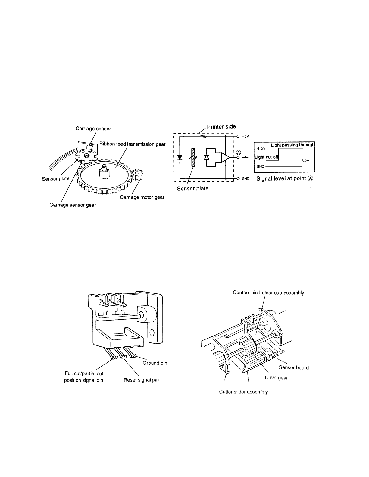
CONFIDENTIAL
Carriage sensor assembly
The carriag e sensor asse mbly detects carriage motor rotation problems by using a rotary
encoder. It consists of a set of gears mounted on the ca rri ag e motor wheel and a carriage sensor.
This sensor uses an LED and photo IC arrangement. On the outer circumference of the carriage
sensor gear, six sensor plates a re mounted with equal spacing . This gear is driven by the carria ge
motor via carriage motor gear and ribbon feed transmission gear. The sensor plates pass
between the LED and photo IC, blocking the li ght and cau sing a change i n the outpu t level of the
photo IC. This chang e is used to generate the carriage m otor rotation signal.
Figure 2-8. Carriage Sensor Circuit DiagramFigure 2-7. Carriage Sensor Assembly
Auto-cutter sensor assembly
The auto-cutter sensor assembly uses the brush con tact p rinciple and consists of the cutte r slider
assembly and a contact pin holder sub-assembly. This sub-assembly carries three contact pins:
for ground, reset signal, and full cut/partial cut (F/P) position signal. The contact pins contact
the print pattern on a sensor board mounted on the cutter slider assembly. When the drive gear
moves the cutter slider assembly, the reset and F/P signals are generated.
Figure 2-9. Contact Pin Holder Sub-assembly Figure 2-10. Relation of Contact Pin
and Contact Board
2-6 Mechanism Configuration and Operating Principles Rev. A
Page 52

CONFIDENTIAL
Slip paper insert sensor assembly
The slip paper insert sensor assembly detects the tip of the paper when slip paper is being
inserted and detects the end of the paper during printing. It is mounted immediately to the right
of the paper set position.
The sensor sub-assembly uses an LED and photo transistor arrangement. When slip paper is
inserted, it blocks the light from the LED and causes a change in the output level of the photo
transistor. This change is used to generate the slip paper presence signal.
TM-U950/U950P Technical Manual
Figure 2-11. Slip Paper and Slip Paper Insert
Sensor Sub-assembly
Figure 2-12. Slip Paper Insert
Sensor Circuit Diagram
Slip paper eject sensor assembly
The slip paper eject assembly is mounted on the right side of the slip paper eject slot. It detects
whether or not the paper has been properly ejected after printing.
The sensor sub-assembly uses an LED and photo transistor arrang ement to dete ct light reflected
by the paper. Since the photo transistor is also subject to external light, the light of the LED is
modulated by turning it on a nd off with a 2-kHz pul se. The outp ut of the photo t ransistor is then
extracted via a 2-kHz filter to inhibit the influence of external light.
Figure 2-13. Slip Paper Eject Sensor Circuit Diagram
Paper roll sensor assembly
The paper roll sensor assembly consists of the paper roll sensor, and paper sensor lever. The
assembly detects the presence of the paper roll.
Rev. A Mechanism Configuration and Operating Principles 2-7
Page 53

CONFIDENTIAL
The paper sensor lever can rotate freely above the upper paper guide and is in constant contact
with the paper roll, due to the internal spring pressure of the microswitch and its own weight.
Therefore, when paper is present in the paper path, the paper sensor lever contacts the paper at
an angle, as shown by the solid line in Figure 2-14, and the microswitch is on. When there is no
paper, the lever moves in the direction and the microswit ch is off, so that the detectio n signal
is generated.
Figure 2-14. Paper Roll Sensor Assembly
Near-end sensor assembly
The near-end sensor assembly consists of the near-end sensor lever, and a microswitch. This
assembly is mounted on the right and left sides of the lower case paper feed section and detects
the remaining amount of paper on the paper roll.
The tip of the near-end sensor lever is pressed against the side of the paper roll by the internal
spring pressure of the microswitch. Therefore, when the paper roll is full, the lever contacts the
paper at an angle, as shown by the solid line in Figure 2-15, a nd the micr oswitch i s on. When the
diameter of the paper roll falls below a user-determined value, the lever moves in the
direction and drops into the paper roll core opening, so that the microswitch is off and the
detection signal is generated.
Figure 2-15. Near End Sensor
2-8 Mechanism Configuration and Operating Principles Rev. A
Page 54
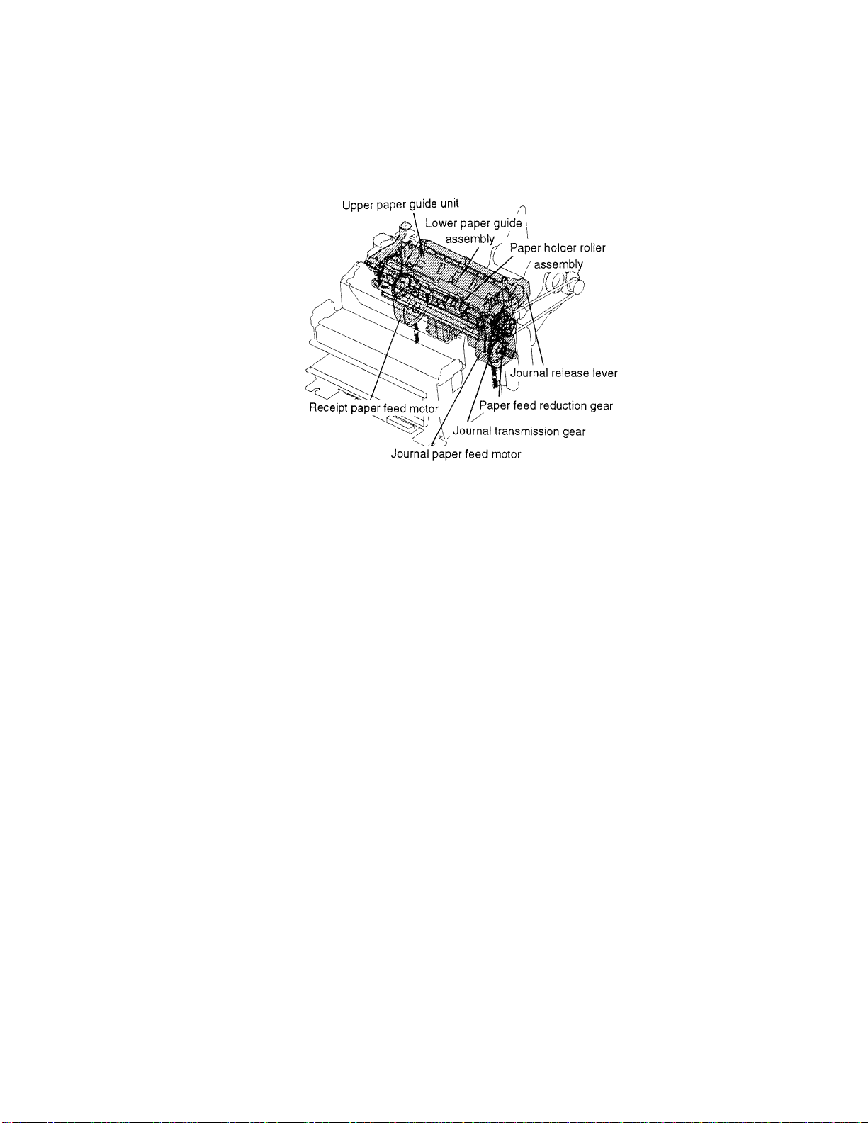
CONFIDENTIAL
Paper Feed Assembly
The paper feed assembly consists of the parts shown in Figure 2-16. The paper feed motors driv e
the entire paper feed operation.
TM-U950/U950P Technical Manual
Figure 2-16. Paper Roll Feed Assembly
Semi-auto loading
A pair of auxiliary paper feed rollers installed on the upper paper guide is linked with the
auxiliary paper holder rollers at constant pressure. The paper feed rollers are linked with the
paper holder rollers at constant pressure. The paper feed rollers and the auxiliary paper feed
rollers are driven by the journal and receipt paper fee d mot ors vi a the J/S switching gear, paper
feed reduction gear, journal transmission gear, and receipt transmission gear.
Immediately before the paper roll insertion point, there is the auxiliary paper feed rollers driven
by the journal and receipt paper feed motors. When paper from the paper roll is handfed to the
auxiliary paper feed rollers, semi-automatic loading is initiated. Paper from the paper roll is fed
through the upper paper guide, lower paper guide, paper holder plate, platen, head carriage,
and auxiliary paper guide to the paper feed rollers.
Rev. A Mechanism Configuration and Operating Principles 2-9
Page 55

CONFIDENTIAL
Immediately before the journal and receipt paper feed motors are driven, the carriage motor is
activated and positions the carriage in the center of the paper width. After passing the paper
feed rollers, the paper lifts the pawl of the auxiliary paper guide and thereby closes the guide.
Therefore the paper from the paper roll cannot be advanced to the paper feed rollers merely by
manual operation.
Figure 2-17. Paper Roll Insertion
Paper feed operation
The paper feed roller at the upper paper guide is linked with the paper holder roller at constant
pressure, and paper on the paper roll is fed in from the paper feed roller. The paper feed roller
shaft in the paper feed roller assembly is equipped with a gear that is driven by the journal
paper feed motor via the J/S switching ge ar, paper feed r eduction ge ar, paper feed transmi ssion
gear, and journal transmission gear.
By driving the journal paper feed motor as described above, the journal-side paper feed roller
turns and advances the paper by a predetermined amount. For receipt side, the paper feed gear
is driven by the receipt paper feed motor via the paper feed reduction gear, paper feed
transmission gear, and receipt transmission gear. By the operati on above, the receipt -side paper
feed roller turns and advances the paper by a predetermined amount.
2-10 Mechanism Configuration and Operating Principles Rev. A
Page 56

CONFIDENTIAL
The auxiliary paper feed roller is set to a slightly smaller value than the paper advance amount.
The difference becomes the slip in the friction clutch between the auxiliary paper feed roll er and
the transmission gear.
TM-U950/U950P Technical Manual
Figure 2-18. Paper Feed Operation (Journal Side)
Paper release operation
Paper release is perform by separat e release levers on the journal and re lease sides. The release
levers are in constant contact with the paper holder roller shaft. When the levers are moved in
the direction shown in Figure 2-19, the pa per holder roller moves, the link with the paper
feed roller is released, and the paper can be removed.
As indicated by the solid line in Figure 2-19, the rel ease leve r is l inked to the pape r hol der rol ler
shaft at both sides, in order not to disturb the paper feed roller and paper holder roller. When
section (A) of the release lever is pushed in the direction, the lever rotates i n the direction,
pivoting around section (B). The paper holder roller shaft and release lever therefore are
Rev. A Mechanism Configuration and Operating Principles 2-11
Page 57
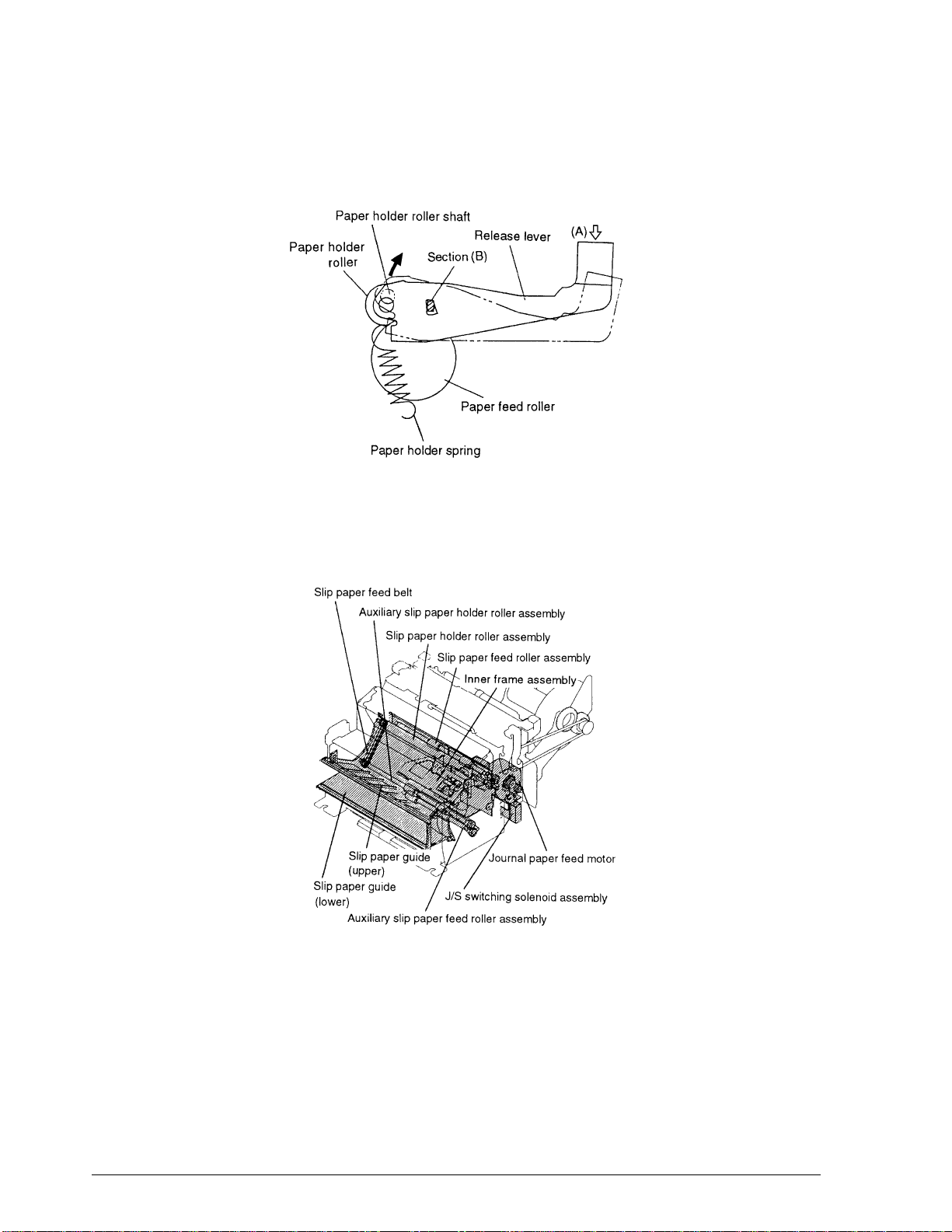
CONFIDENTIAL
separated from the paper feed roller (the dotted line in Figure 2-19). When section (A) of the
release lever is not pushed farther, the paper holder spring returns the lever to the original
position.
Figure 2-19. Paper Release Operation
Slip Paper Assembly
The slip paper assembly consists of the parts shown in Figure 2-20.
Figure 2-20. Slip Paper Feed Assembly
2-12 Mechanism Configuration and Operating Principles Rev. A
Page 58

CONFIDENTIAL
Slip paper positioning operation
A form stopper placed at a right angle in the slip paper p ath bloc ks the pa th du e to the ac ti on of
the form stopper spring (Figure 2-21).
When the slip paper is inserted along the slip paper guide (lower) in the direction, the paper
can enter as far as the stopper (Figure 2-21).
Next, the J/S switching sole noid i s po wered whi le rot ati ng the jou rnal p aper feed moto r sev era l
steps in the forward and backward directions. The J/S change lever now causes the J/S
switching gear, which has been positioned to feed the journal paper up to this point, to move to
a position to feed the slip paper. The auxilia ry slip paper feed solenoid is then powered, causing
the auxiliary slip paper feed shaft l ever l in ked to the fe rrite core to move in the dire cti on.
The roller of the auxiliary slip paper feed roller is pushed up against the auxiliary slip pa per
holder roller. The auxiliary slip paper feed shaft lever moves the form stopper in the
b
direction, thus opening the slip paper path and completing the preparations for slip paper
feeding (Figure 2-21).
The journal paper feed motor now rotates a certain number of steps (depending on the slip
paper format) in the direction, causing the J/S switching gear, paper feed reduction gear, sl ip
paper holder roller, slip paper feed belt, au x iliary slip paper holder rolle r, and auxiliary slip
paper feed roller to move in turn and thus bring the slip paper into the printing position (Figure
2-23).
TM-U950/U950P Technical Manual
a
Immediately before the operating sequence described above, the head carriage is moved to the
right most position. When positioning is completed, the auxiliary slip paper feed solenoid is
turned off, and the J/S switching solenoid is set to hold (during slip paper printing and paper
feeding).
Figure 2-21. Slip Paper Positioning (1)
Rev. A Mechanism Configuration and Operating Principles 2-13
Page 59

CONFIDENTIAL
Figure 2-22. Slip Paper Positioning (2)
.
Figure 2-23. Slip Paper Positioning (3)
2-14 Mechanism Configuration and Operating Principles Rev. A
Page 60

CONFIDENTIAL
.
Slip paper feed operation
TM-U950/U950P Technical Manual
Figure 2-24. Slip Paper Positioning Timing Chart
Following slip paper positioning, printing can be performed. After each line is printed, the
journal paper feed motor is ac tivated and tu rns the slip paper feed roller to ad vance the paper
by a predetermined amount. Slip paper forward feed and reverse feed is controlled by selecting
the journal paper feed motor drive signal.
The gear train of the slip paper feed assembly consists of the journal paper feed motor gear, J/S
switching gear (moved by the J/S switching solenoid to the slip paper feed gear train), paper
feed reduction gear, slip paper feed roller, and gear of auxiliary slip paper feed roller.
Since the driving force of the jour nal paper feed motor is transmitted v ia the gear trai n to the slip
paper feed roller and the slip paper holder roller, the slip paper is controlled from both sides.
For forward feed, each ge ar turns in the direction, direction, and the
a
direction. The slip paper feed roller and slip paper holder roller turn in the and
b
d
c
e
directions, so that the slip paper moves i n the direction. For reverse feed, the above directi ons
are reversed.
Figure 2-25. Slip Paper Feed Operation
Rev. A Mechanism Configuration and Operating Principles 2-15
Page 61

CONFIDENTIAL
MICR Reader Assembly (for printers with a MICR reader) (not available for the TM-U950P)
The main components of this assembly include those shown in the slip assembly section of this
chapter, namely the MICR head assembly, carriage motor assembly, head carriage assembly,
frame carriage assembly, MICR head ho lder c hange lev er, MI CR head holder frame, MICR hea d
holder lever, MICR head holder roller, MICR transmission pulley, and MICR transmission belt.
This assembly i s installed at th e factory, as an option, in the paper path of the slip assembl y
shown later in this chapter.
MICR reading and reverse-side printing operations
Check paper is inserted in the same way as slip paper, with the check paper following along
below the right end of the slip paper guide and being inserted from the direction. After
reaching the form stopper, the check paper is positioned for printing (see Figure 2-26).
At this point, the slip entrance detector detects the presence of the check paper. Next, the top of
the check paper is positioned by the slip assembly, as described in the Slip Paper Assembly
section of this chapter, so that the check paper is ready for feeding (see Figure 2-26).
Next, the journal motor rotates in the same way as with slip feeding, at the MICR reading speed,
and begins to carry the leading edge of the check paper the specified number of steps from the
form stopper to the MICR head assembly.
At this point, the head carriage assembly is moved by the carriage motor assembly the specified
number of steps, then waits (see Figure 2-27).
In response to this movement of the head carr iage assembly, the MI CR head holder change lev er
moves in the direction, and the MICR head holder roller is pressed against the MICR
head assembly, in the direction, so that the check paper is caught between the roller and
the assembly.
Because the MICR head holder roller comes between the MICR transmission belt and the MICR
transmission pulley and is normally synchronized to the rotation of the slip holder roller
assembly, the movement of the head carriage assembly causes the shifted MICR head holder
roller, with the check paper caught in it, to transport the check paper from the point where it is
pressed against the MICR head assembly at the MICR reading speed to be read by the MICR.
Next, the check paper moves to a position conforming to the reverse-side printing format, and
the check paper is confirmed to be effective.
At this point, if the MICR characters could not be discerned easily, the reading operation is
repeated. (If problems occur with the second reading, or if the MI CR character waveform cannot
by detected, the check paper is ejected without being printed.)
a
a
When the check paper has been confirmed to be effective, printing is carried out on the reverse
side by the head carriage assembly, in the specified format, and the paper is ejected, thus
concluding the printing operation.
2-16 Mechanism Configuration and Operating Principles Rev. A
Page 62

CONFIDENTIAL
The gear operation of this assembly, which carries out MICR reading of the check paper,
backfeeding, and reverse-side printing, is the same as that of the slip feeding assembly. The only
element which differs from the slip feeding assembly is the speed.
TM-U950/U950P Technical Manual
Figure 2-26. Check Paper Positioning (1)
Figure 2-27. Inserting the Check Paper
Rev. A Mechanism Configuration and Operating Principles 2-17
Page 63

CONFIDENTIAL
Ribbon Feed Assembly
The ribbon feed assembly is mounted on the right side of the carriage frame and consists of the
parts shown in Figure 2-28.
Figure 2-28. Ribbon Feed Assembly
Ribbon feed operation
When the carriage motor gear turns in the direction, the rotation is transmitted to the
ribbon feed transmission gear and planet gear. The planet gears and rotate around the
small gear wheel of the ribbon feed transmission gear, moving in the direction. This
movement causes the ribbon feed planet lever to rotate in the direction, and the planet
2 3 3
gear moves until it interlocks with the planet gear . Since the planet gear is always
interlocke d with the rib b on feed gear , the ribbon feed gear rotates in the d irection.
When the carriage motor gear rotates in the direction, the ribbon feed transmission gear
rotates in t he direction, and the planet gears and rotate and move in the
f 1 2
a
1 2
b
c
d
e
direction.
This movement causes the ribbon feed planet lever to rotate in the direct ion, so that the
planet gear mo ves until it interlocks with the ribbon feed gear, causing this gear to rotate in
the direction.
1
d
h
g
2-18 Mechanism Configuration and Operating Principles Rev. A
Page 64

CONFIDENTIAL
TM-U950/U950P Technical Manual
Therefore, the ribbon feed gear always turns in the direction, regardless of the rotation
direction of the carriage motor. The ribbon feed gear is interlocked with the ribbon feed roller
and ribbon feed holder roller inside the ribbon cassette, thus feeding the ribbon.
Figure 2-29. Ribbon Feed Operation
h
Stamp Assembly (for printers with a stamp assembly)
The optional stamp assembly consists of the parts shown in Figure 2-30. The assembly is
installed below the paper inlet on the receipt side.
Figure 2-30. Stamp Assembly
Rev. A Mechanism Configuration and Operating Principles 2-19
Page 65
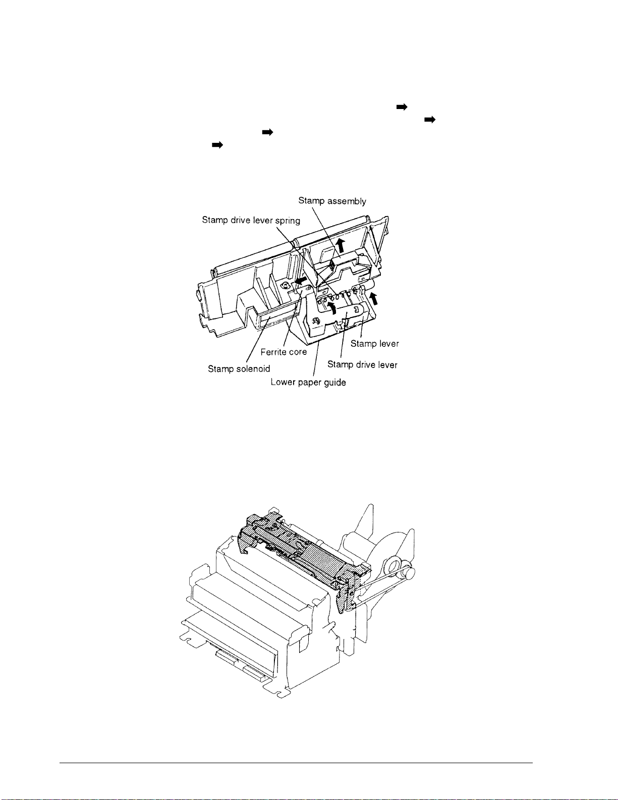
CONFIDENTIAL
Stamp operation
When the stamp solenoid is powered , the fe rri te cor e moves in t h e direction. Since the ferrite
core serves as the pivot for the stamp drive leve r, the lever rotates in the direction , causing
the linked stamp lever to move in the direction. Therefore, the stamp assembly attached to
the lever also moves in the direction and is pushed up against the upper paper guide, thus
stamping the paper. When the st amp so lenoi d goes o ff, the fo rce o f the st amp d rive lev er sp ri ng
returns the sta mp to its origina l position.
Figure 2-31. Stamp Operation
Auto-cutter Assembly
The auto-cutter assembly consists of the transmission mechanism, sensor, and cutter. For easy
maintenance and paper removal, this assembly can be completely opened. For the sensor, see
auto-cutter sensor assembly on page 2-6.
Figure 2-32. Auto-cutter Assembly
2-20 Mechanism Configuration and Operating Principles Rev. A
Page 66

CONFIDENTIAL
Transmission mechanism
The transmission mechanism consists of the cutter motor gear fastened on the cutter motor
shaft, two reduction gears A, the reduction gear B, two drive gears on the drive gear shaft, and
the cutter sl ider assembly. The cutter motor rotation is reduced and transmitted to the drive
shaft via the reduction gears A and B. The gears on the drive shaft then translate the rotary
motion into a sliding motion for o p eration of the cutter slider.
TM-U950/U950P Technical Manual
Figure 2-33. Auto-cutter Transmission Mechanism
Cutter mechanism
The cutter mechanism consists of the cutter blade frame, cutter blade, and cutter blade cover.
The mechanism performs either a full or a partial cut, depending on the F/P position signal
supplied by the sensor assembly.
Figure 2-34. Auto-cutter Mechanism
Rev. A Mechanism Configuration and Operating Principles 2-21
Page 67
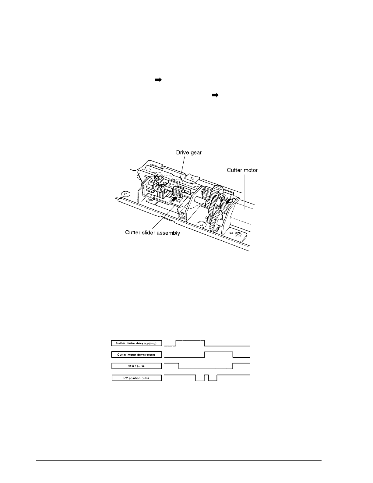
CONFIDENTIAL
Cutting operation
When the cutter motor is activated while the mechanism is in the home position (when the
cutter blade does not protrude thr ough the slit of the cutter blade cover and the r eset si gna l i s at
high), the cutter motor rotates in the direction an d the rotational force is transmitted to the
transmission gear train. This in turn causes the drive gear in the upper section of the cu tter slider
assembly to turn, thereby moving the cutter slider in the direction.
Since the cutter blade is linked to the dowel on the rear of the cutter slider assembly, it moves
with the slider and cuts the paper at the slit.
After the cut is performed, the polarity of the cutter motor drive current is reversed, so that the
reverse motion returns the cutter blade to the home position.
Figure 2-35. Auto-cutter Operation
Full cut operation
When the cutter motor is activated while the mechanism is in the home position, the reset signal
changes from high to low, but the F/P position signal is maintained at high. When the motor
continues to be powered and cutting starts, the F/P position signal changes from high to low. If
the cutter motor is only turned off when this signal again becomes high, the cutter slider
assembly movement stops after a full cut.
Figure 2-36. Full Cut Operation Timing Chart
2-22 Mechanism Configuration and Operating Principles Rev. A
Page 68
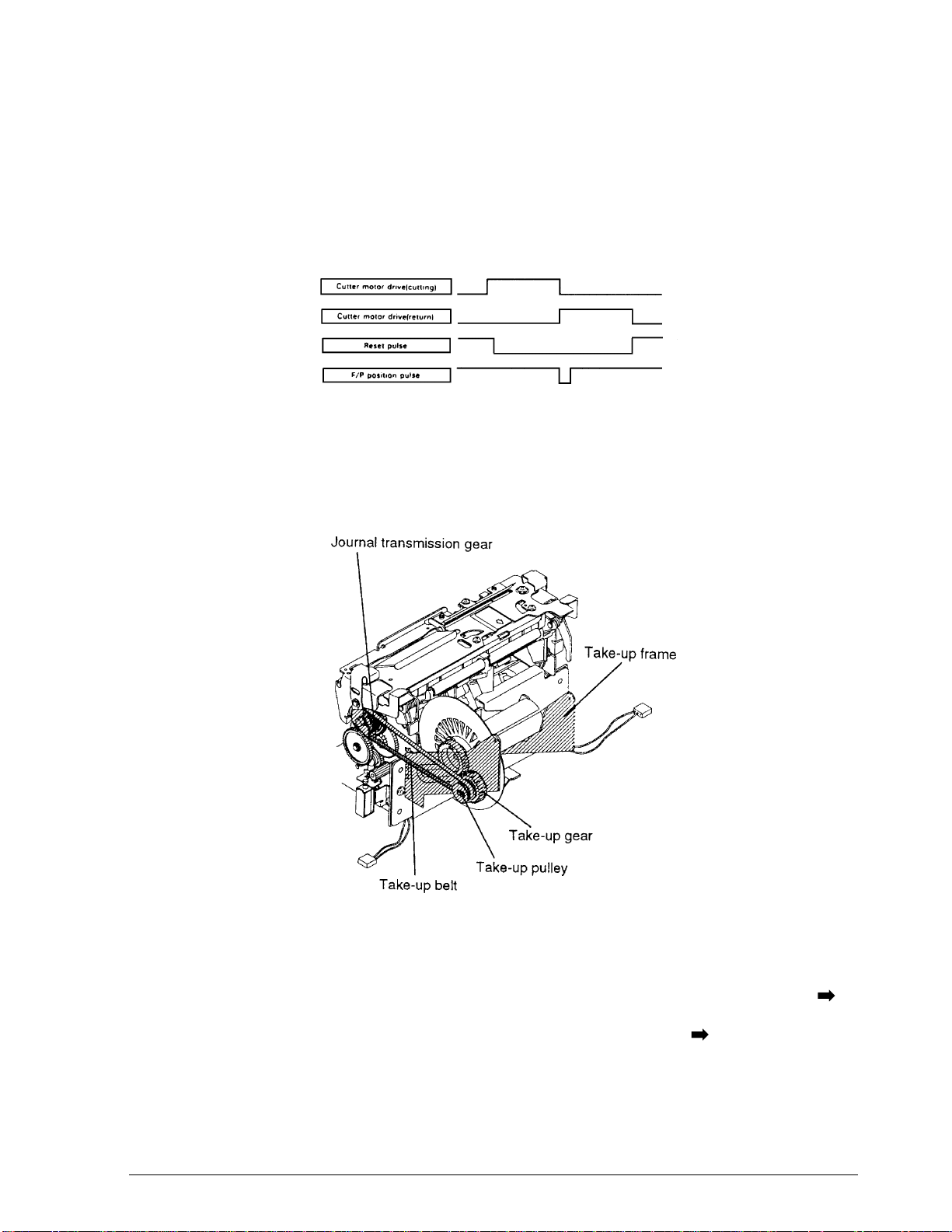
CONFIDENTIAL
Partial cut operation
When the cutter motor is activated while the mechanism is in the home position, the reset signal
changes from high to low, but the F/P position signal is maintained at high. When the motor
continues to be powered and cutting starts, the F/P position signal changes from high to low. If
the cutter motor is only turned off at this point, th e cutter sli der asse mbly movement sto ps after
a partial cut.
Paper Roll Take-up Assembly
This assembly consists of the ta ke-up frame, jo urnal transmission gear, take-up belt, take-up
pulley, and take-up gear. It assures stable take-up of the paper roll.
TM-U950/U950P Technical Manual
Figure 2-37. Partial Cut Operation Timing Chart
Figure 2-38. Paper Roll Take-up Assembly
Take-up operation
When the journal paper feed motor turns, the journal paper feed motor gear rotates in the
direction, and the rotational force is transmitted to the J/S switching gear and paper feed
reduction gear. This causes the journal transmission gear to rotate in the direction. Since this
Rev. A Mechanism Configuration and Operating Principles 2-23
Page 69
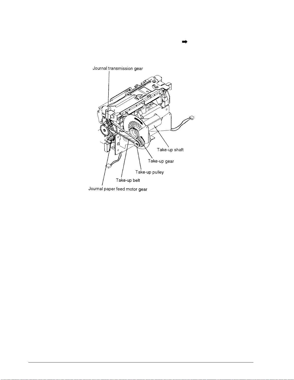
CONFIDENTIAL
gear is linked to the take-up belt, the take-up pull ey turns in the direction. The take-up clutch
spring mounted between the take-up pulley and take-up gear transmits the force to the take-up
gear and thus to the take-up shaft, which turns to take up the paper.
Figure 2-39. Take-up Operation
2-24 Mechanism Configuration and Operating Principles Rev. A
Page 70
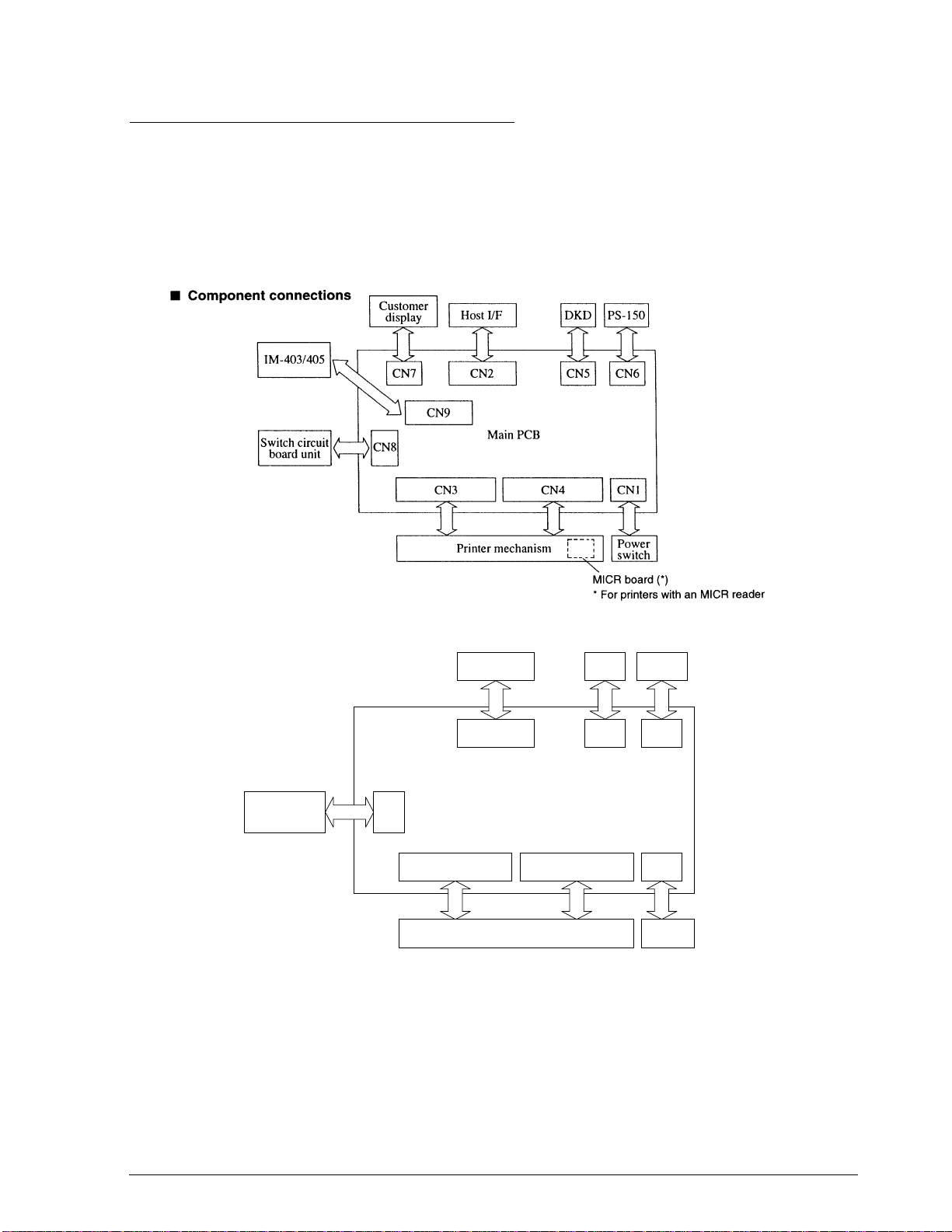
CONFIDENTIAL
Electrical Circuitry Operating Principles
Hardware Configuration
The electrical circuitry of the TM-U950 is divided into the main PCB and the switch PCB unit.
These connections are shown in Figs. 2-40, 2-41, and 2-42.
❏ MICR board (for printers with an MICR reader) (not available for the TM-U950P)
TM-U950/U950P Technical Manual
Figure 2-40. TM-U950 Component Connection Chart
Host I/F DKD PS-150
CNIF1 CN5 CN6
Switch circuit
board unit
Figure 2-40a. TM-U950P Component Connection Chart
CN8
Circuit Board Unit
CN3 CN4 CN1
Printer mechanism
Power
switch
The main board, switch board, and MICR board (on printers with an MICR reader) contain the
following electrical circuits.
Rev. A Mechanism Configuration and Operating Principles 2-25
Page 71

CONFIDENTIAL
Switch PCB unit
❏ FEED buttons
❏ LEDs (power, paper status, and error)
❏ Cover open sensor
Main PCB
❏ Power supply circuit
❏ Reset circuit
❏ CPU
❏ Memory (ROM: 512 KB, RAM: 64 KB, EEPROM)
❏ Gate array
❏ Operation panel control circui t
❏ Host interface circuit
❏ Drawer kick-out circuit
❏ Print head drive circuit
❏ Solenoid drive circuits
❏ Paper feed motor drive circuit
❏ Auto-cutter control
❏ Carriage motor drive circuit
❏ Actuator irregular operation protection circuit
❏ Mechanism sensor circuits
❏ IM-403/405 connection circuit (not supported by the TM-U950P)
MICR board (on printers with an MICR reader) (not available on the TM-U950P)
❏ Power supply section (eliminates power supply noise)
❏ Input section (protects against excessive voltage)
❏ Amplifier section
❏ Signal limiting section
❏ Signal switching section
❏ Self-bias current supplier
2-26 Mechanism Configuration and Operating Principles Rev. A
Page 72
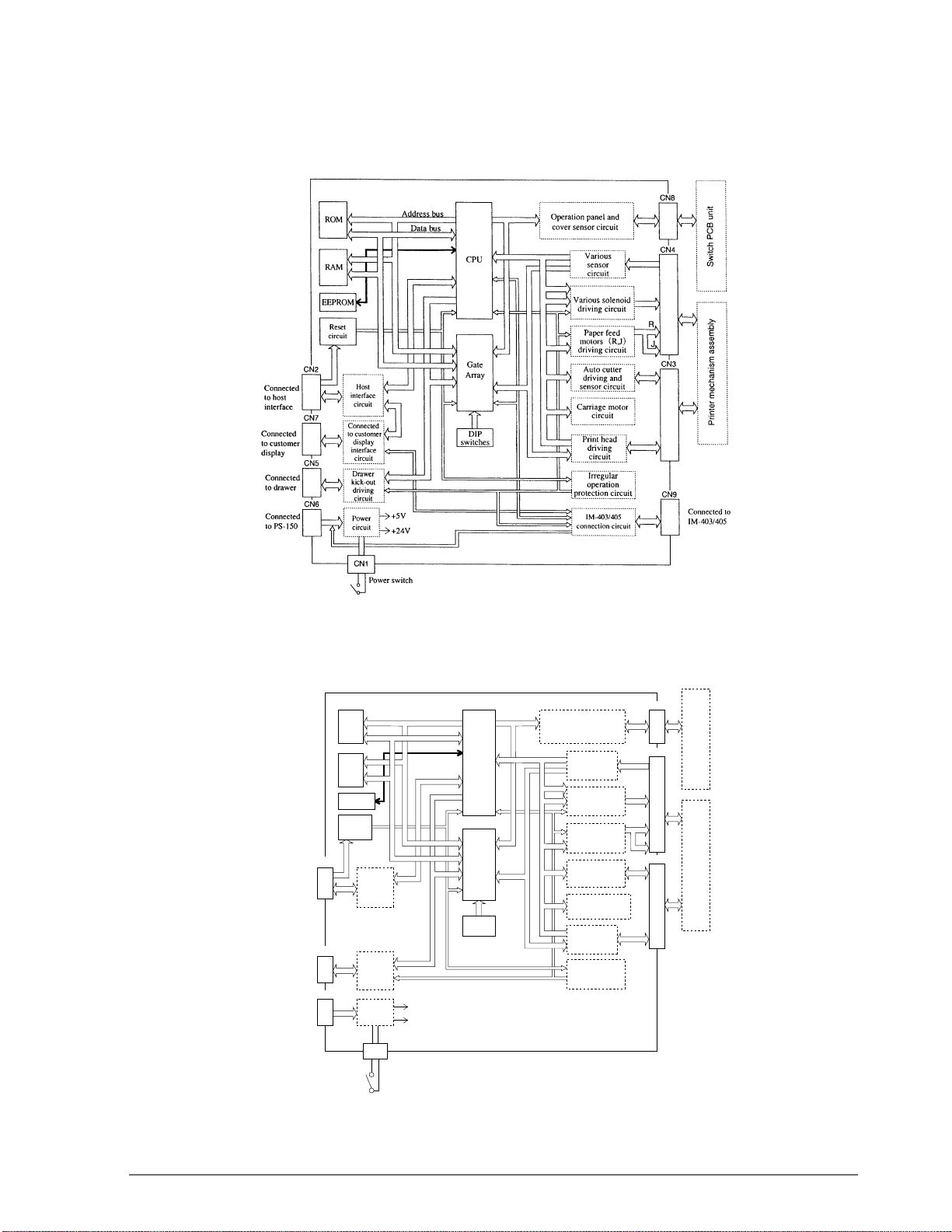
CONFIDENTIAL
TM-U950/U950P Technical Manual
Main Circuit Board Assembly
Figure 2-41. Block Diagram of TM-U950 Main Board
Circuit Board Unit
Connected
to host
interface
Connected
to drawer
Connected
to PS-150
CNIF1
CN5
CN6
ROM
RAM
EEPROM
Reset
circuit
Host
interface
circuit
(parallel)
Drawer
kick-out
driving
circuit
Power
circuit
CN1
Address bus
+5V
+24V
Power switch
Data bus
CPU
Gate
Array
DIP
switches
Operation panel and
cover sensor circuit
Various
sensor
circuit
Various solenoid
driving circuit
Paper feed
motors (R,J)
driving circuit
Auto cutter
driving and
sensor circuit
Carriage motor
circuit
Print head
driving
circuit
Irregular
operation
protection circuit
CN8
CN4
R
J
CN3
Switch PCB unitPrinter mechanism assembly
Figure 2-41a. Block Diagram of TM-U950P Main Board
Rev. A Mechanism Configuration and Operating Principles 2-27
Page 73
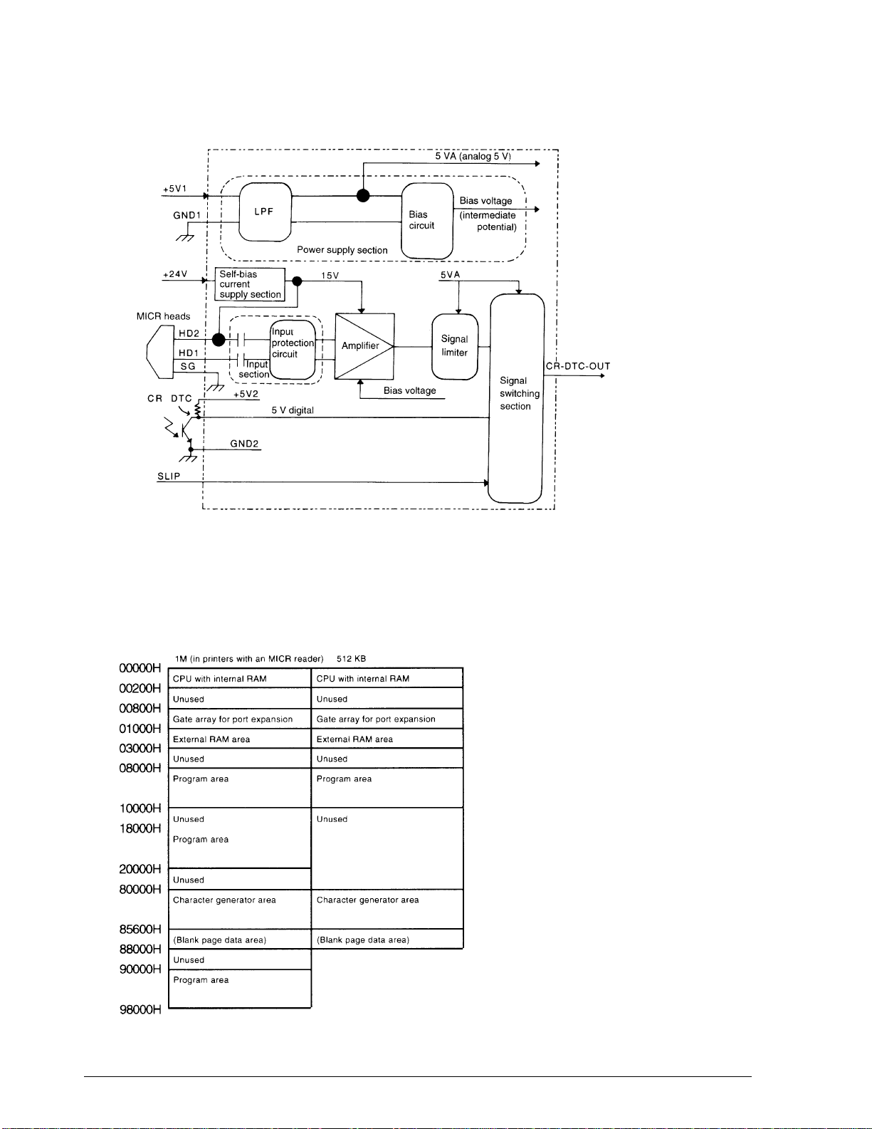
CONFIDENTIAL
Figure 2-42. MICR Board Block Diagram (on printers with an MICR reader)
(not available for the TM-U950P)
Memory map
This printer incorporates a 512 KB ROM (1 M in printers with an MICR reader, which is not
available for the TM-U950P) and 64 KB of RAM. The memory map is as shown below.
Figure 2-43. Memory Map
2-28 Mechanism Configuration and Operating Principles Rev. A
Page 74

CONFIDENTIAL
Reset circuit for the TM-U950
The reset IC (M51953BFP) monitors the +5 V voltage. When the voltage becomes more than 4.5
V, the IC releases the reset condition for the CPU and other circuits, thus enabling normal
printer operation. When a reset signal from the host is sent from the host interface (DSR, #25)
more than 1 ms, the output of the reset IC becomes low and the CPU and other cir cui ts are reset.
TM-U950/U950P Technical Manual
Figure 2-44. Reset Circuit for the TM-U950
Reset circuit for the TM-U950P
The reset IC (M51953BFP) monitors the +5 V voltage. When the voltage becomes more than 4.5
V, the IC releases the reset condition for the CPU and other circuits, thus enabling normal
printer oper ation. When the interface re set signal (nInit , #31) is added to the reset circuit more
than 50 µs when the host interface is i n forward di rection transmissio n (I/F signal 12 84 ACT, #36
is low), the reset IC becomes low and the CPU and other circuits are reset.
+5V
R12
R13
6
4
RESET OUT
C35
CN1
1284ACT
nInit
+5V
DSW2
871
R14
R11
RESCTL
Q10
Q4
C19
SG
DM1
2
3
7
IN OUT
5
C GND
+
C17
_
Figure 2-44a. Reset Circuit for the TM-U950P
Rev. A Mechanism Configuration and Operating Principles 2-29
Page 75

CONFIDENTIAL
Main Board Operating Principle
Power supply circuit for the TM-U950
The 24 V DC at CN6 (when IM-403/405 is not connected) or at CN9 (when IM-403/405 is
connected) is filtered and supplied to the +24 V line and the +5 V regulator circuit. The +5 V
regulator circuit uses the switching method to convert the +24 V input into a +5 V output. The
switching regulator IC (U9) switches the +24 V DC. The voltage is smoothed by L18, D13, and
C49, and is supplied as the +5 V output.
Figure 2-45. Power Supply Circuit for the TM-U950
Power supply circuit for the TM-U950P
The 24 V DC at CN6 is filte red and suppl ied t o the +24 V line and the +5 V regulat or cir cui t. The
+5 V regulator circuit uses the switching method to convert the + 24 V input into a +5 V output.
The switching regulator IC (U9) switches the +24 V DC. The voltage is smoothed by L18, D13,
and C49, and is supplied as the +5 V output.
( TO
POWER SW )
1
+24V
+24V
GND
NC
1
2
2
D14
CN1
+24V
IN
FG
CN6
1
F1
2
1
1
2
2
3
3
4
SH
FG
L12
C28
R10
C10
C27
+24V
GP
U9
12
VIN SW
R224
+
C51
_
G
N
F/B
D
4
L18
3
D13
+5V
+
C49
_
SG
Figure 2-45a. Power Supply Circuit for the TM-U950P
2-30 Mechanism Configuration and Operating Principles Rev. A
Page 76

CONFIDENTIAL
Control circuitry
CPU (M37702)
The CPU controls all printer operations according to a control program in ROM. The CPU pin
assignments are shown in Table 2-1.
Table 2-1. CPU Pin Assignments
Pin
number
1 ANO V_DTC I Analog Detect 24 V voltage
2 P67 PFR2 O TTL Receipt paper feed motor Phase C,D
3 P66 PFR1 O TTL Receipt paper feed motor Phase A, B
4 P65 PFJ2 O TTL Journal paper feed motor Phase C, D
5 P64 PFJ1 O TTL Journal paper feed motor Phase A, B
6 P63 DSR I TTL
7P62
8 P61 PFR_HL I/O TTL Receipt paper feed motor hold H = hold
9 P60 PFJ_HL I/O TTL Journal paper feed motor hold H = hold
10 P57 DKD_2 O TTL Drawer kick-out drive signal 1 L = drive
11 P56 DKD_1 O TTL Drawer kick-out drive signal 2 L = drive
12 P55 AC_2 O TTL Auto-cutter motor drive signal 2
13 P54 AC_1 O TTL Auto-cutter motor drive signal 1
14 P53 SHB O TTL Slip paper holder solenoid drive signal L=drive
15 P52 ER_LED O TTL Error LED drive signal L = ON
16 P51 SL_LED O TTL Slip paper LED drive signal L = ON
17 P50 CSOK O TTL
18 P47 STB O TTL Stamp solenoid drive signal L = ON
19 P46 CR_NM O TTL
20 P45 CR_HL O TTL Carriage motor control signal H = hold
21 P44 CR_2 O TTL Carriage motor control signal Phase C, D
22 P43 CR_1 O TTL Carriage motor control signal Phase A, B
23 (0) FAI O TTL Receive interrupt
24 (RDY
25 (HOLD
26 BYTE BYTE I TTL Fixed to H (pulled up to +5V)
27 (CNV
28 (RESET
CPU function Signal designation I/O Level Description
TM-U950/U950P Technical Manual
DSR signal input from serial interface on the
host
CSTRB(CSTB for the
TM-U950P)
) (RDY) I TTL Fixed to H (pulled up to +5V)
)(HOLD) I TTL Fixed to H (pulled up to +5 V)
)(CNV
ss
)(RESET) I TTL Reset signal input L = reset
) I TTL Fixed to H (connected to +5 V)
ss
I TTL Not used (receive interrupt for the TM-U950P)
Slip paper eject detector LED drive signal L =
ON
Carriage motor control signal H = normal
rotation
Rev. A Mechanism Configuration and Operating Principles 2-31
Page 77

CONFIDENTIAL
Table 2-1. CPU Pin Assignments (continued)
Pin
number
29 x
30 X
31 (E
32 (V
33 HLDA HLDA O TTL Unused (open)
34 ALE ALE O TTL Address latch enable signal H = address latch
35 BHE BHE O TTL Unused (open)
36 (R/W
37 A23/D7
38 A22/D6
39 A21/D5
40 A20/D4
41 A19/D3
42 A18/D2
43 A17/D1
44 A16/D0
45 A15 A15 O TTL Address signal Bit 15
46 A14 A14 O TTL Address signal Bit 14
47 A13 A13 O TTL Address signal Bit 13
48 A12 A12 O TTL Address signal Bit 12
49 A11 A11 O TTL Address signal Bit 11
50 A10 A10 O TTL Address signal Bit 10
51 A9 A9 O TTL Address signal Bit 9
52 A8 A8 O TTL Address signal Bit 8
53 A7 A7 O TTL Address signal Bit 7
54 A6 A6 O TTL Address signal Bit 6
55 A5 A5 O TTL Address signal Bit 5
CPU function Signal designation I/O Level Description
in
OUT
)(E) O TTL Enable signal L = Data read/write)
)(V
ss
)(R/W) O TTL Read/write signal H = read, L = write
(xin) I TTL Clock input
(X
) O TTL Clock input
OUT
) - GND Power supply
ss
A23 O TTL Address signal Bit 23
D7 I/O TTL Data signal Bit 7
A22 O TTL Address signal Bit 22
D6 I/O TTL Data signal Bit 6
A21 O TTL Address signal Bit 21
D5 I/O TTL Data signal Bit 5
A20 O TTL Address signal Bit 20
D4 I/O TTL Data signal Bit 4
A19 O TTL Address signal Bit 20
D4 I/O TTL Data signal Bit 3
A18 O TTL Address signal Bit 18
D2 I/O TTL Data signal Bit 2
A17 O TTL Address signal Bit 17
D1 I/O TTL Data signal Bit 1
A16 O TTL Address signal Bit 16
D0 I/O TTL Data signal Bit 0
2-32 Mechanism Configuration and Operating Principles Rev. A
Page 78

CONFIDENTIAL
Table 2-1. CPU Pin Assignments (continued)
Pin
number
56 A4 A4 O TTL Address signal Bit 4
57 A3 A3 O TTL Address signal Bit 3
58 A2 A2 O TTL Address signal Bit 2
59 A1 A1 O TTL Address signal Bit 1
60 A0 A0 O TTL Address signal Bit 0
61 P87 TXD O TTL TXD signal output for the interface circuit board
62 P86 RXD I TTL
63 P85 DTR O TTL DTR signal output for the interface circuit board
64 P84 CTS1 O TTL Unused (pulled down to (Vss))
65 P83 IMSD I TTL
66 P82 IMSD I TTL
67 P81 IMDTR_TM O TTL
68 P80 CTSO O TTL Unused (pulled down to (Vss))
69 (V
70 (AV
71 (V
72 (AV
73 (V
74 P77 CACT I TTL Auto-cutter full/partial signal
75 P76 CACR I TTL Auto-cutter reset signal
76 P75 CCRP I TTL Carriage detachment sensor signal
77 P74 CHP I TTL Home position sensor signal
78 AN3 CSOE I Analog Slip paper eject sensor signal
79 AN2 CSLPIN I Analog Slip paper insert sensor signal
80 AN1 CHDTH I Analog Print head temperature sensor signal
CPU function Signal designation I/O Level Description
cc
cc
ref
ss
) - - GND Power supply
ss
TM-U950/U950P Technical Manual
RXD signal input from the interface circuit
board
SD signal output for the IM-403/405 serial
interface (not used on the TM-U950P)
RD signal input from the IM-403/405 serial
interface (not used on the TM-U950P)
DTR signal output for the IM-403/405 serial
interface (not used on the TM-U950P)
) - - +5V Power supply
) - - +5V Analog power supply
) - - +5V Analog reference voltage
) - - GND Analog power supply
ROM (512 KB, [1 M in printers with an MICR reader])
The ROM contains the printer control program and the character generator. The control
program governs the basic printer functions. The CPU operat es entirely under the control of this
program.
RAM (64 KB)
The RAM is used for the following:
❏ As input buffer for data received via the connector interface.
Rev. A Mechanism Configuration and Operating Principles 2-33
Page 79

CONFIDENTIAL
❏ As print buffer for pattern data to be sent to the print head
❏ As storage area for CPU processing functions (flags, pointers, etc.)
EEPROM
The EEPROM stores the slip paper insert sensor lev el. Data exchange wit h the CPU is performed
via a serial link.
Gate array
The gate array is a five I/O port type with an eight-bit (see Table 2-2). It serves two purposes. It
can be used by the CPU for I/O port expansion, as speci fied in the memory map (port expansion
function). When the ALE signal goes high, the gate array also latches to the multiplexed
address/data signal output by the CPU and extracts the address signal (address latch function).
Table 2-2. Gate Array Pin Assignments
Pin number Gate array function Signal designation` I/O Level Description
1(RSET
2 PA 0 HEAD 8 O TTL Print head 8 L = ON
3 PA 1 HEAD 7 O TTL Print head 7 L = ON
4 PA 2 HEAD 6 O TTL Print head 6 L = ON
5 PC 6 JN_LED O TTL Print head 5 L = ON
6 PA 3 HEAD 5 O TTL Print head 4 L = ON
7 PA 4 HEAD 4 O TTL Print head 3 L = ON
8 PA 5 HEAD 3 O TTL Print head 2 L = ON
9 PA 6 HEAD 2 O TTL Print head 1 L = ON
10 PA 7 HEAD 1 O TTL Print head 0 L = ON
11 GND - - GND Power supply
12 PB 0 SW1I I TTL DIP switch bank 1 serial input
13 PB 1 SW2I I TTL DIP switch bank 1 serial input
14 PB 2 SWCK I TTL DIP switch settings read clock
15 PB 3 SWSL I TTL DIP switch bank select
16 PB 4 SCB O TTL S/J switching solenoid drive signal L = drive
17 PB 5 S/J HL O TTL S/J switching solenoid hold signal L = hold
18 PB 6 HD_COM O TTL Print head common L = ON
19 PB 7 HEAD 9 O TTL Print head L = ON
20 PC 0 E2DI I TTL Data input from EEROM
21 PC 1 E2DO O TTL Data output from EEROM
22 PC 2 E2CK O TTL EEROM select output
23 PC 3 E2CE O TTL EEROM select output
24 PC 4 IMDSR I TTL
)(RSET) I TTL Reset signal input L = reset
DSR signal input from the IM-403/405 serial
interface (unused on the TM-U950P)
2-34 Mechanism Configuration and Operating Principles Rev. A
Page 80

CONFIDENTIAL
Table 2-2. Gate Array Pin Assignments (continued)
Pin number Gate array function Signal designation` I/O Level Description
25 PC 5 POW_TRG O TTL Power control trigger signal
26 PD 0 IF_DET I TTL
27 PD 1 CLK_REQ I TTL
28 GND - - GND Power supply
29 GND - - GND Power supply
30 V
31 PD 2 SRTS 0 TTL
32 PD 3 N. C I TTL Unused (connected to GND)
33 PD 4 N. C I TTL Unused (connected to GND)
34 PD 5 N. C I TTL Unused (connected to GND)
35 PD 6 N. C I TTL Unused (connected to GND)
36 PD 7 N. C I TTL Unused (connected to GND)
37 PD 0 CJNE I TTL Journal near-end signal
38 PE 1 CRNE I TTL Receipt near-end signal
39 PE 2 CJPE I TTL Journal paper-end signal
40 PE 3 CRPE I TTL Receipt paper-end signal
41 PE 4 PFR_SW I TTL Receipt FEED switch L = ON
42 PE 5 PFJ_SW I TTL Journal FEED switch L = ON
43 PE 6 COVER I TTL Cover open detection
44 PE 7 DK_S I TTL Drawer status signal
45 PC 7 PC_LED O TTL Receipt LED L = ON
46 (STRB
47 BUSY RTS O TTL
48 (CSTRB
49 (CRDY
50 GND _ _ GND Power supply
51 CRIN CRIN I TTL Unused (connected to GND)
52 (CROUT
53 AB 0 A 0 I TTL Address signal Bit 0
54 AB 1 A 1 I TTL Address signal Bit 1
DD
TM-U950/U950P Technical Manual
Unused (connected to GND) on TM-U950 I/F
circuit board identify signal on TM-U950P
Unused (connected to GND) on TM-U950
synchronization clock request signal for TMU950P
--+5VPower supply
Unused (connected to GND) on TM-U950,
software RTS output on TM-U950P
) CLK I TTL Unused (connected to GND) on TM-U950
synchronization clock interrupt for the TMU950P
Unused (open) for TM-U950. RTS output for
the I/F circuit board for the TM-U950P
)CSTB OTTL
)SRTS ITTL
)(CROUT)OTTLUnused (open)
Unused on TM-U950, receive interrupt on TMU950P
Unused (connected to GND) for the TMU950, software RTS input for TM-U950P
Rev. A Mechanism Configuration and Operating Principles 2-35
Page 81

CONFIDENTIAL
Table 2-2. Gate Array Pin Assignments (continued)
Pin number Gate array function Signal designation` I/O Level Description
55 AB 2 A 2 I TTL Address signal Bit 2
56 AB 3 A 3 I TTL Address signal Bit 3
57 AB 4 A 4 I TTL Address signal Bit 4
58 (R/W
59 (CS
60 (E
61 ASTB ASTB I TTL Address latch enable signal
62 ALB 0 A 16 O TTL Address signal Bit 16
63 ABL 1 A 17 O TTL Address signal Bit 17
64 ABL 2 A 18 O TTL Address signal Bit 18
65 ABL 3 A 19 O TTL Address signal Bit 19
66 ABL 4 N. C O TTL Unused (open)
67 ABL 5 N. C O TTL Unused (open)
68 ABL 6 N. C O TTL Unused (open)
69 ABL 7 N. C O TTL Unused (open)
70 GND — — GND Power supply
71 GND — — GND Power supply
72 (V
73 DB 0 D 0 I/O TTL Data signal Bit 0
74 DB 1 D 1 I/O TTL Data signal Bit 1
75 DB 2 D 2 I/O TTL Data signal Bit 2
76 DB 3 D 3 I/O TTL Data signal Bit 3
77 DB 4 D 4 I/O TTL Data signal Bit 4
78 DB 5 D 5 I/O TTL Data signal Bit 5
79 DB 6 D 6 I/O TTL Data signal Bit 6
80 DB 7 D 7 I/O TTL Data signal Bit 7
)(R/W) I TTL Read/write signal
)(CS) I TTL Chip select signal L = select
)(E)ITTLEnable signal
) — — +5V Power supply
ss
Operation panel and cover open sensor circuits
There are five LEDs on the operation panel (POWER, ERROR, RECEIPT OUT, JOURNAL OUT,
and SLIP) and two buttons (RECEIPT FEED, and JOURNAL/SLIP FEED). The cover open
sensor uses a photosensor.
These parts are mounted directly on the switch PCB unit, which is linked to the main PCB
assembly via connectors (CN8).
2-36 Mechanism Configuration and Operating Principles Rev. A
Page 82
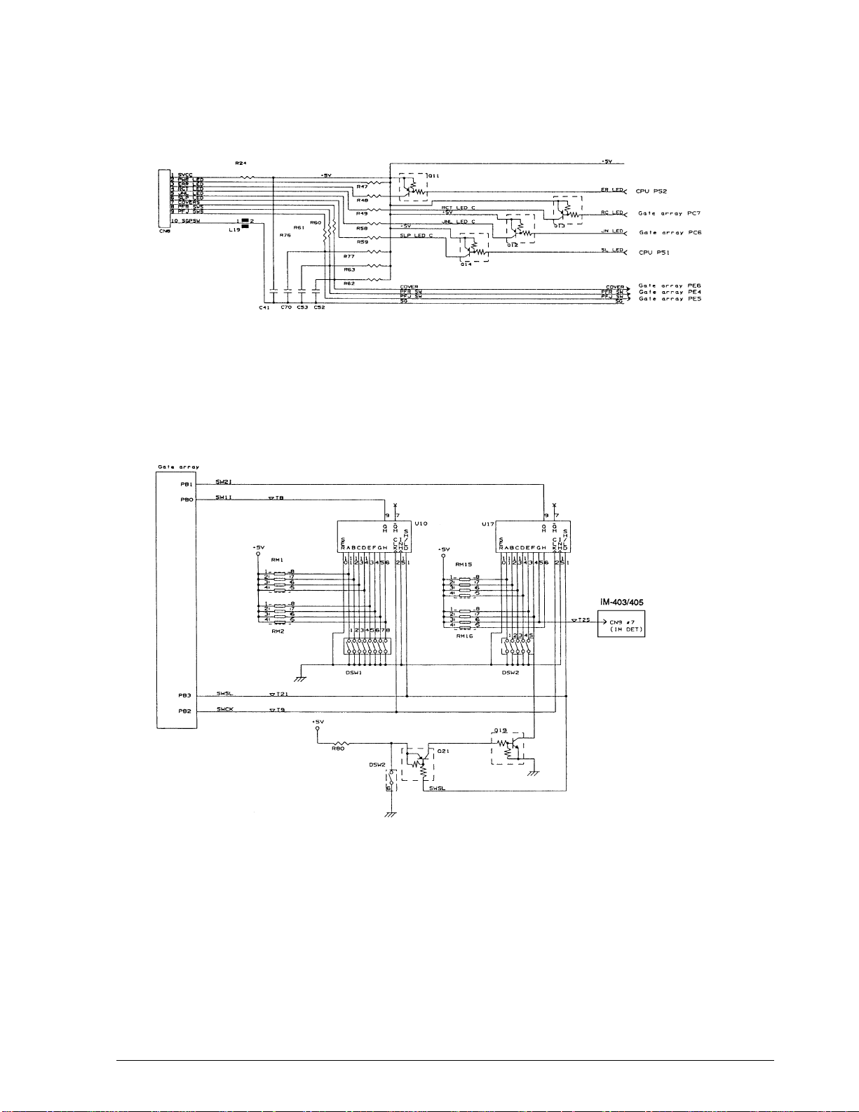
CONFIDENTIAL
LED drive as well as switch and photosensor status detection is performed by the CPU. For
signal I/O, the CPU ports and the expansion ports on the gate array are used.
Figure 2-46. Operation Panel and Cover Open Sensor Circuits
DIP switch circuit
Parallel-to-serial conversion of the settings of DIP switch banks 1 and 2 is performed by the
conversion IC (U10, U17), and the result is input to the gate array port (PB0, PB1). DIP switch
selection is made by the SWSL signal (PB3). The SWCL signal (PB2) is used as a clo ck signa l a nd
the switch settings are read one bit at a time.
TM-U950/U950P Technical Manual
Figure 2-47. DIP Switch Circuit for the TM-U950
Rev. A Mechanism Configuration and Operating Principles 2-37
Page 83
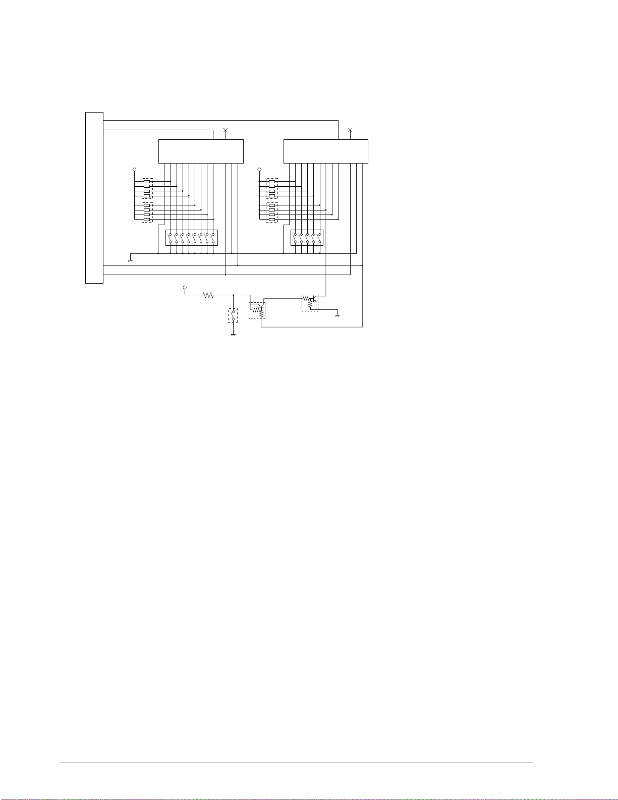
CONFIDENTIAL
Gate array
SW2I
PB1
SW1I ⁄ T8
PB0
U10 U17
S
E
A
{ 5V
R
RM1
0
1
8
2
7
3
6
4
5
1
8
2
7
3
6
5
4
RM2
9
OHO
GFEDCB
H
141312111
5
4
3
6
76543218
7
\
H
S
H
I
C
/
N
L
L
H
K
D
{ 5V
152
1
S
E
A
R
RM15
0
8
1
7
2
6
3
5
4
8
1
7
2
6
3
5
4
RM16
9
7
\
OHO
H
S
H
I
C
GFEDCB
54321
/
N
L
L
H
H
K
D
543141312111
152
6
1
SWCL ⁄ T21
PB3
SWCK ⁄ T19
PB2
DSW1 DSW2
{ 5V
R80
DSW2
6
Q21
SWSL
Q19
Figure 2-47a. DIP Switch Circuit for the TM-U950P
Host interface circuit for the TM-U950
The printer has an RS-232C interface for connection to the host computer and a DM inter face for
connection to the customer display (DM).
The driver/receiver ICs (U2 and U3) handle level conversion (TTL ↔ ± 12V) for the RS-232C
and customer display interface signals.
Figure 2-45 shows device connection block diagrams illustrating the connections between the
printer (TM), host computer (HOST) and customer display (DM).
In connection (b), printing on the TM is possible by using the passthro ugh function of the DM. In
connection (c), to send data to the DM through the TM, the RXD signal terminal (pin 3) of the
host interface connector (CN2) on the TM and is connected directly to the RXD signal (pin 3) of
the customer display interface connector (CN7).
Pins 6 and 25 of the interface connector carry the printer reset signal, which is selectable by DIP
switch. (Refer to SW 7 and 8 of switch bank 2 in Table 1-8, DIP switch settings.) Then select the
Seiko Epson customer display by setting DIP switch 6 on the bank 1 to ON. When this setting is
in effect, the RTS signal which is output will be the AND of the DTR signal from the customer
display and the DTR signal from the printer.
2-38 Mechanism Configuration and Operating Principles Rev. A
Page 84

CONFIDENTIAL
When neither the customer display nor the printer DTR signal is SPACE, the RTS signal is not
SPACE either. When DIP switch 6 of the bank 1 is OFF, the same signal as the printer’s DTR
signal is output to the RTS signal.
TM-U950/U950P Technical Manual
Figure 2-48. Host Interface Circuit and Customer Display Interface Circuit
Rev. A Mechanism Configuration and Operating Principles 2-39
Page 85
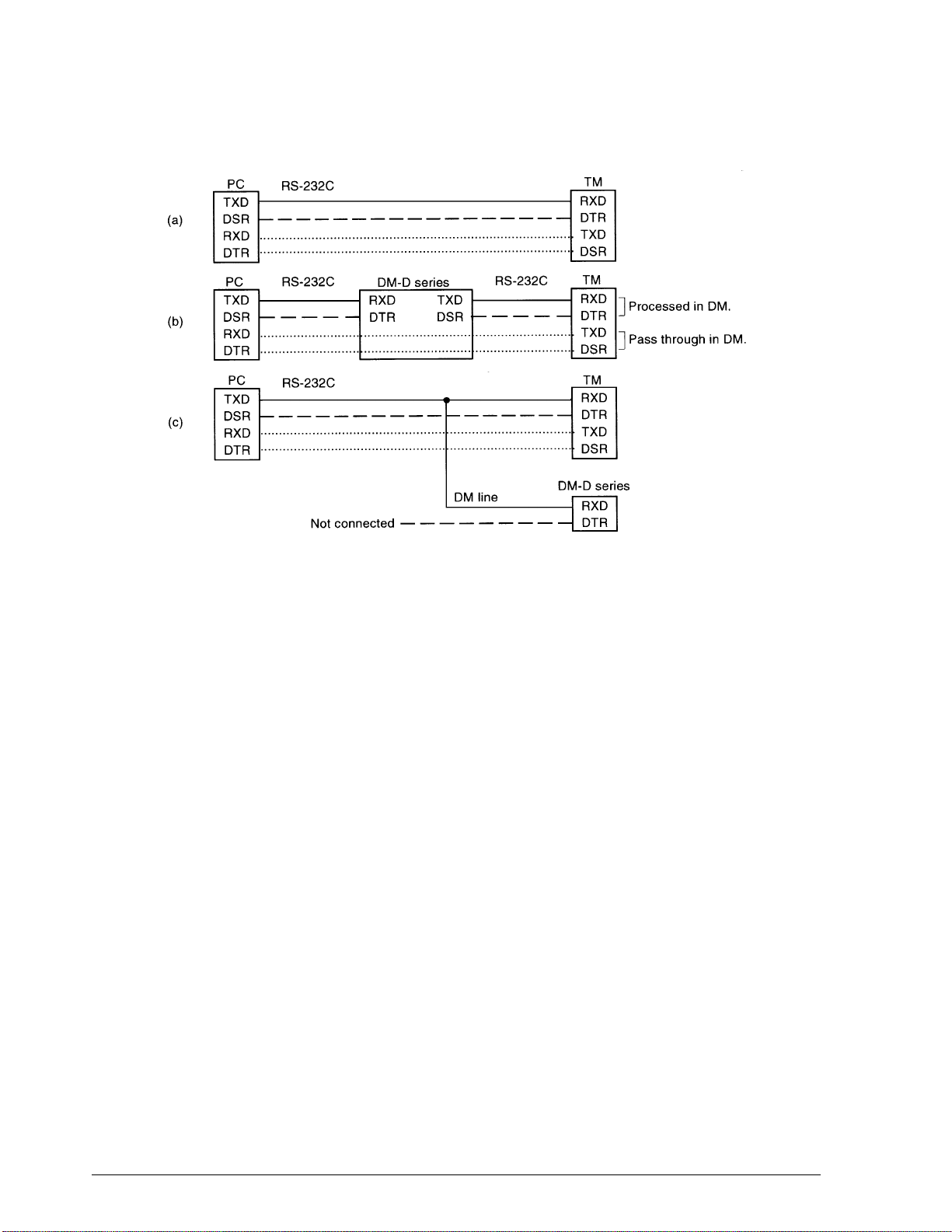
CONFIDENTIAL
Figure 2-49. Device Connection Block Diagram
Host interface circuit for the TM-U950P
TM-U950P printer has an IEEE 1284 interface for connection to the host computer. Control CPU (I/F
circuit board U2) controls the transmission between the host computer, and the CPU converts the
received data to the serial data, and then the CPU sends the data to the main ci rcu it board. TTL IC (I/
F circuit board U1, U9, U10) drives or receives the interface signal. Transmission between host has
other mode, IEEE 1284 Nibble/Byte mode which is the reverse directional transmission .
Drawer kick-out circuit
The DKD_1 and DKD_2 signals from the CPU set the drawer kick-out driver transistors Q7 and
Q8 to on; they in turn output the drawer open signal. The drawer status signal DK_S is input to
the gate array, allowing the host to check the status via the interface.
The +24 V drawer power supply is controlled by the three-pin regulator (U1) which cuts off the
supply in case of excessive current.
2-40 Mechanism Configuration and Operating Principles Rev. A
Page 86
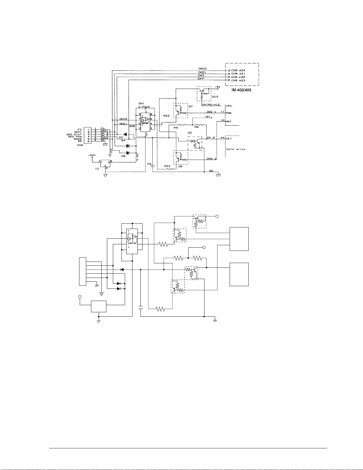
CONFIDENTIAL
The drawer drive signal is also supplied to the IM-403/405 through CN9 for the TM-U950 only.
Figure 2-50. Drawer Kick-out Circuit for the TM-U950
TM-U950/U950P Technical Manual
Q15
UNTRG-HIZ
{ 5V
DK S
DKD 2
SG
{ 5V
11
10
44
CPU
PS6
PS7
PE7
Gate array
DKD1
DKD STAT
DKD POW
DKD2
CN5
1 FG
1
FG
2 DKD1
2
3 DK S
3
4 DK P
4
5 DKD2
5
6 SG
6
SG
{ 24V
12
U1
@ F
@ G
IO
G
3
DKD2
DKD1
D4
D6
QM1
G-PS24
9
7
5
3
D5
D
K
P
1
8
6
4
2
1
0
C9
R22
R23
Q7
DKD 1
R9 R8
Q2
Q8
Figure 2-50a. Drawer Kick-out Circuit for the TM-U950P
Print head drive circuit
The print head has nine pins that are driven by dedicated solenoids. Ports PA0 - PA7 and PB 7 of
the gate array carry the solenoid signals (HEAD1 - 9). PB7 carries the common signal for the
solenoids (HD_COM). The HEAD1 - 9 signals activate the sync transistors (QM3 - QM5). The
HD_COM signal activates the source transistors (Q24, Q33, and Q34) to power the solenoids.
When the source transistors go off, the energy stored by the solenoids is dissipated via the
flywheel diodes (D39, D40, D44, D45, D46, and D47). When the sync transistors go off, the
solenoid current is cut.
Rev. A Mechanism Configuration and Operating Principles 2-41
Page 87
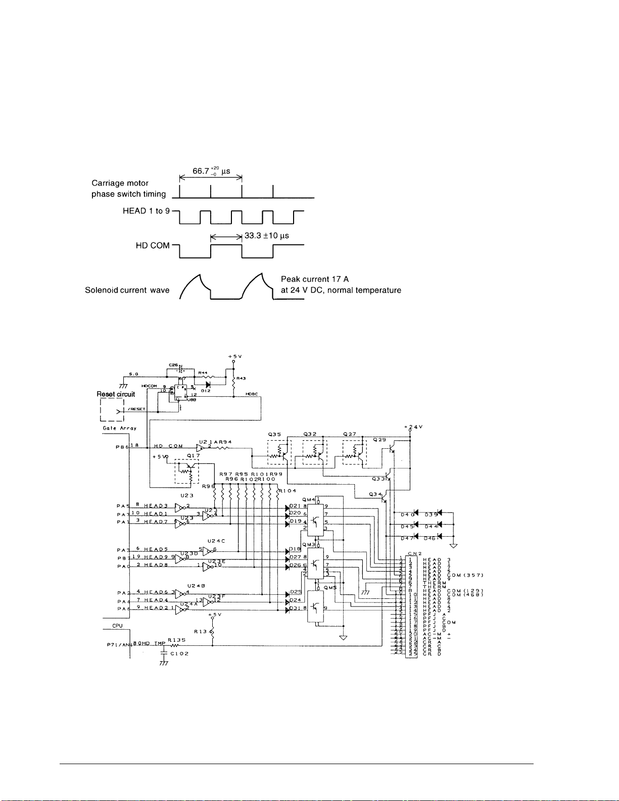
CONFIDENTIAL
The HDBC signal is a head current limiter. When the head current duration exceeds 0.1s due to
an error, this signal turns the head off. The limit time is determined by C20 and R44 and
retriggered at the falling edge of the HD_COM signal.
Head temperature is measur ed by feedi ng the v oltag e divid ed by the ther mistor and R134 to the
CPU via the analog port AN1.
Figure 2-51. Print Head Timing Chart
Figure 2-52. Print Head Drive Circuit
2-42 Mechanism Configuration and Operating Principles Rev. A
Page 88
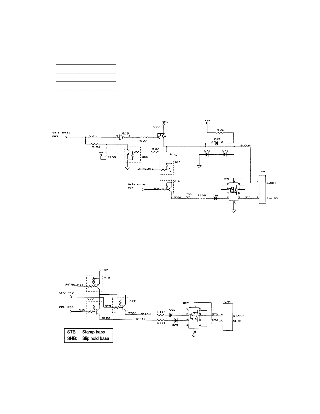
CONFIDENTIAL
S/J switching solenoid drive circuit
The solenoid hold and off status is controlled by the SCB and S/J_HL signals.
S/J_DR S/J_HL Operation
LLDrive
LHHold
HHOff
TM-U950/U950P Technical Manual
Figure 2-53. S/J Switching Solenoid Drive Circuit
Auxiliary slip paper feed solenoid/stamp solenoid drive circuit
These solenoids are driven by transistors QM5 according the STB and SHB signals from the
CPU.
Figure 2-54. Auxillary Slip Paper Feed Solenoid/Stamp Solenoid Drive Circuit
Rev. A Mechanism Configuration and Operating Principles 2-43
Page 89

CONFIDENTIAL
Paper feed motor drive circuit (journal)
When transistor QM2 becomes on in response to the PFJ1 and PFJ2 switching signals from the
CPU, the paper feed motor is activated. The PFJ_HL signal switches the motor between drive
and hold. During hold, Q28 goes off and a current is supplied from the 5 V power supply.
The same circuit is provided for the receipt side.
Figure 2-55. Paper Feed Motor Timing Chart
Figure 2-56. Paper Feed Motor Drive Circuit
2-44 Mechanism Configuration and Operating Principles Rev. A
Page 90

CONFIDENTIAL
Auto-cutter drive circuit
The auto-cutter drive circuit uses the dedicated DC motor drive IC TA8428K. The CPU issues
the AC_1 and AC_2 signals to control off, normal, reverse, and braking operations of the autocutter motor.
AC_1 AC_2 Operation
LLOff
H L Normal
LHReverse
H H Brake
TM-U950/U950P Technical Manual
Figure 2-57. Auto-cutter Drive Circuit
Carriage motor drive circuit
The carriage motor is driven by a dedicated constant-current IC. The CPU issues the mutual
switching signals CR_1 and CR_2 and the constant-current switching signals CR_HL and
CR_NM. In response to these signals, the IC controls the carriage motor via the OUTA, OUTA
OUTB, and OUTB
CR_HL CR_NM Operation
0 0 Speed up / slow down
0 1 Normal rotation
10 Hold
terminals.
,
Rev. A Mechanism Configuration and Operating Principles 2-45
Page 91

CONFIDENTIAL
Figure 2-58. Carriage Motor Timing Chart
Figure 2-59. Carriage Motor Drive Circuit
2-46 Mechanism Configuration and Operating Principles Rev. A
Page 92

CONFIDENTIAL
TM-U950/U950P Technical Manual
Actuator irregular operation protection circui
This circuit protects the printer from a current duration due to CPU abnormal operation.
POW_TRG signal is connected to gate arr ay PC5 and U8A is tr ig gered by the signal. POW_TRG
signal is a trigger for power supply control, and the signal is cut when CPU operates
abnormally. As a result of the cut, all the actuator drivers except the print head and the autocutter are turned off.
t
Figure 2-60. Irregular Operation Protection Circuit
Mechanism sensor circuits
All the sensors except the slip paper insert and eject sensors receive signals from the printer
mechanism, and the signals are input to CPU and gate array via pull-up resistance and integral
circuit.
Rev. A Mechanism Configuration and Operating Principles 2-47
Page 93

CONFIDENTIAL
Slip paper insert sensor circuit
The slip paper insert sensor signal is output to CPU analog port via pull-down resistance and
integral circuit. Slip paper existence is judged by comparison between the threshold value in
U20 and the detected value. (For the threshold value, see Adjustment in Chapter 5.)
Figure 2-61. Slip Paper Insert Sensor Circuit
Slip paper eject sensor circuit
Slip paper eject detection is performed using a reflecting photosensor. To prevent errors due to
external light, 2-kHz frequency modulation is used. The SO_K signal (light source drive) is
turned on and off by the CPU i n a 2-kH z cy cle . T he SO_ E signal (light source detection) passes a
2-kHz filter and amplifier. The CPU then reads the l ev el of t h i s sig nal (CSOE ) v ia an ana log p ort
to determine the presence or absence of paper.
Figure 2-62. Slip Paper Eject Sensor Circuit
2-48 Mechanism Configuration and Operating Principles Rev. A
Page 94

CONFIDENTIAL
MICR Board Operating Principle (on printers with an MICR reader) (not available for the TM-U950P)
Operating principle of the MICR reader
“MICR” stands for “Magnetic Ink Character Recognition”. Magnetic ink is different from ink
normally used for printing in that it contains magnetic particles such as iron filings which
magnetize the ink.
When a magnetic field is applied from a certain direction to the magnetic ink characters printed
on check paper, the characters are magnetized, as shown in the diagram below. (The term
“magnetic ink” is used in this manual, but in actuality, the characters are read by sending
current to a magnetic reading head and forming a magnet.)
TM-U950/U950P Technical Manual
Figure 2-63. Magnetization of the Magnetic Ink Characters.
Characters magnetized in this way are read by the magnetic reading head, and character
recognition is carried out.
Figure 2-64. Operation of the Magnetic Reading Head
Rev. A Mechanism Configuration and Operating Principles 2-49
Page 95

CONFIDENTIAL
The voltage waveform output from the magnetic reading head produces a different pattern for
each individual character, and characters are recognized by their patterns.
Figure 2-65. Voltage Waveform Output From the Magnetic Reading Head
Overview of MICR board operation
The following drawing shows a simplified diagram of the functions of the MICR board.
Figure 2-66. General Operation of the MICR Board
The MICR head reading signal and CR DTC signal are output to the CR DTC OUT terminal.
Switching of these two signals is controlled by the SLIP signal as shown below.
SLIP signal
High
Low
CR DTC OUT terminal
CR DTC signal output
MICR head reading signal output
(Note: Only the logic for High and Low is shown. These are different from the TTL levels.)
2-50 Mechanism Configuration and Operating Principles Rev. A
Page 96
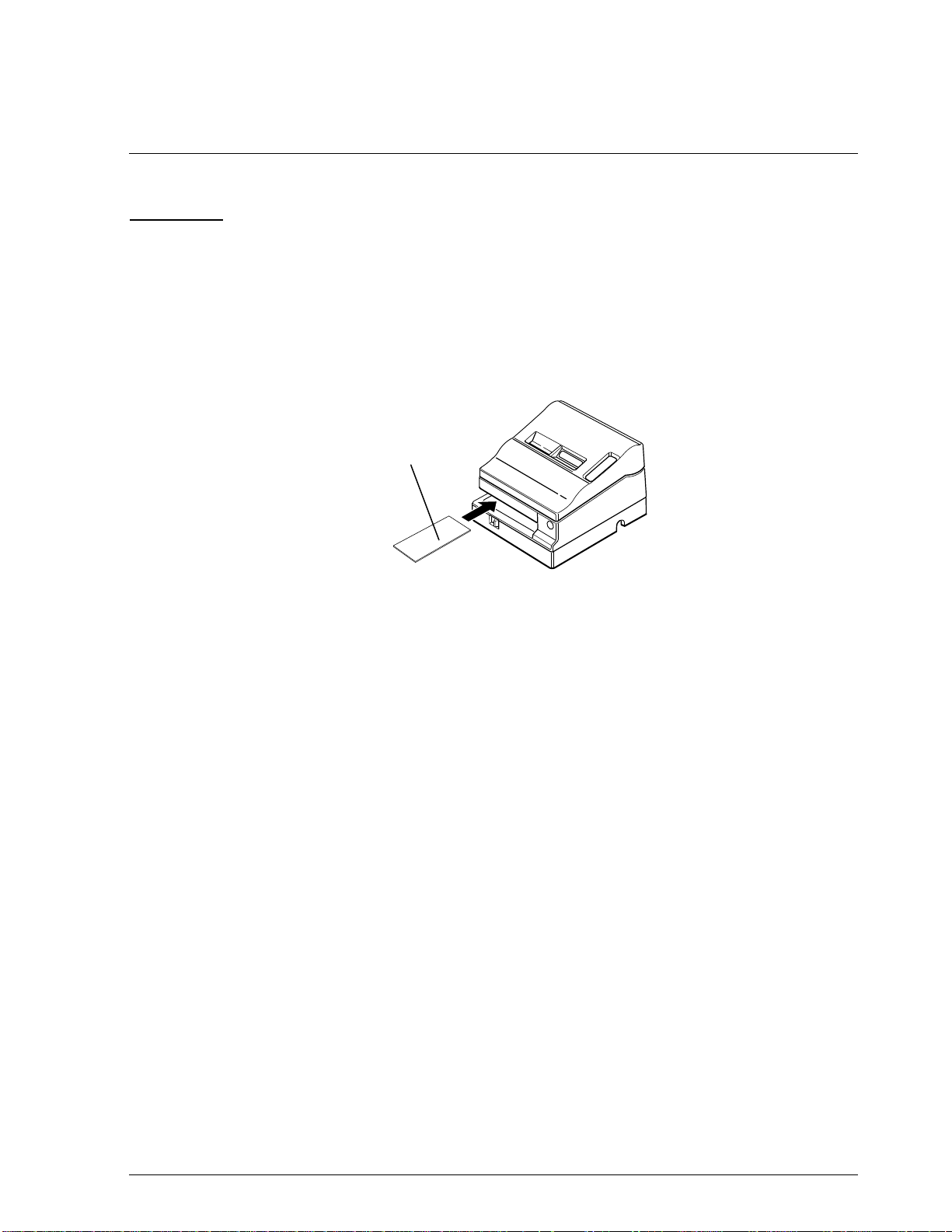
CONFIDENTIAL
Chapter 3
Handling and Maintenance
Handling
Handling Precautions
Transport Precautions
❏ When transporting the print er, i nsert t he pr otec ti ve mat eri al in the sl ip pa per pat h and pa ck
the printer in a specially provided package so that the printer does not come into contact
with other products. Also, be careful not to drop it or apply any kind of external stress.
TM-U950/U950P Technical Manual
Protective
Material
Figure 3-1. Inserting the Protective Material
Storage Precautions
❏ Avoid storing th e printer in an area that is dusty, humid, or subj ect to excessively low
temperatures. Also avoid areas wh ich are e xposed to direct sunl ight for l ong period s of time.
❏ For long-term storage, put the printer in a polyethylene bag with anti-rust paper (VCI
paper), and ke ep it in a dry plac e.
Use Precautions
❏ Always install a ribbon ca sse tte and load paper before prin t ing . If pap er runs out, be sure to
load new paper before resumi ng printing.
If printing is executed when there is no paper or no ribbon cassette in the printer, the print
quality may deteriorate (the printing color may become uneven or some dots may not be
printed) because of damage to the surface of the platen, printing wires, or ribbon.
❏ Do not touch the print head unit after printing. It becomes very hot during printing.
❏ There is a set screw for the frame ground (FG.) Use it for grounding the printer.
❏ Be careful when wiring and connecting the interface, power, and drawer kick-out cables to
avoid subjecting the connectors to excessive pressure.
Rev. A Handling and Maintenance 3-1
Page 97

CONFIDENTIAL
Ribbon Cassette Handling Precautions
❏ Use only the ribbon cassette specified in this manu al. (See the Ink Ribbon section in Chapter
1.)
If another ribbon cassette is used, the print quality may deteriorate, the life of the printer
may be shortened, ink may leak, or the ribbon may be caught on a print head pin.
❏ Do not reink a ribbon.
If a ribbon is reinked, the print quality could deteriorate due to a malfunction of the print
wires or the in k may leak.
Notes on using the MICR reader (only when the printer is used with MICR)
❏ Be sure to perform personal check printing with a paper roll loaded. If MICR reading and/
or printing is performed without a paper roll loaded, the check cannot be fed correctly or
may be damaged due to paper jams.
❏ The personal checks must be flat, without curls, folds, or wrinkles (especially at the edges).
Otherwise, the check may rub against the ribbon and become ink-stained.
Loading the Paper Rolls
1. Cut the end of the paper rolls straight as shown in the figure below:
Insertion
Direction
2. Turn on the printer, open the printer cover, and remove the take-up spool.
3. Insert paper rolls in both the receipt and journal sides of the printer.
Correct
Correct Incorrect Incorrect
Figure 3-2. Paper Roll Edge
Printer cover
Incorrect
Take-up spool
Figure 3-3. Inserting Paper Roll
3-2 Handling and Maintenance Rev. A
Page 98
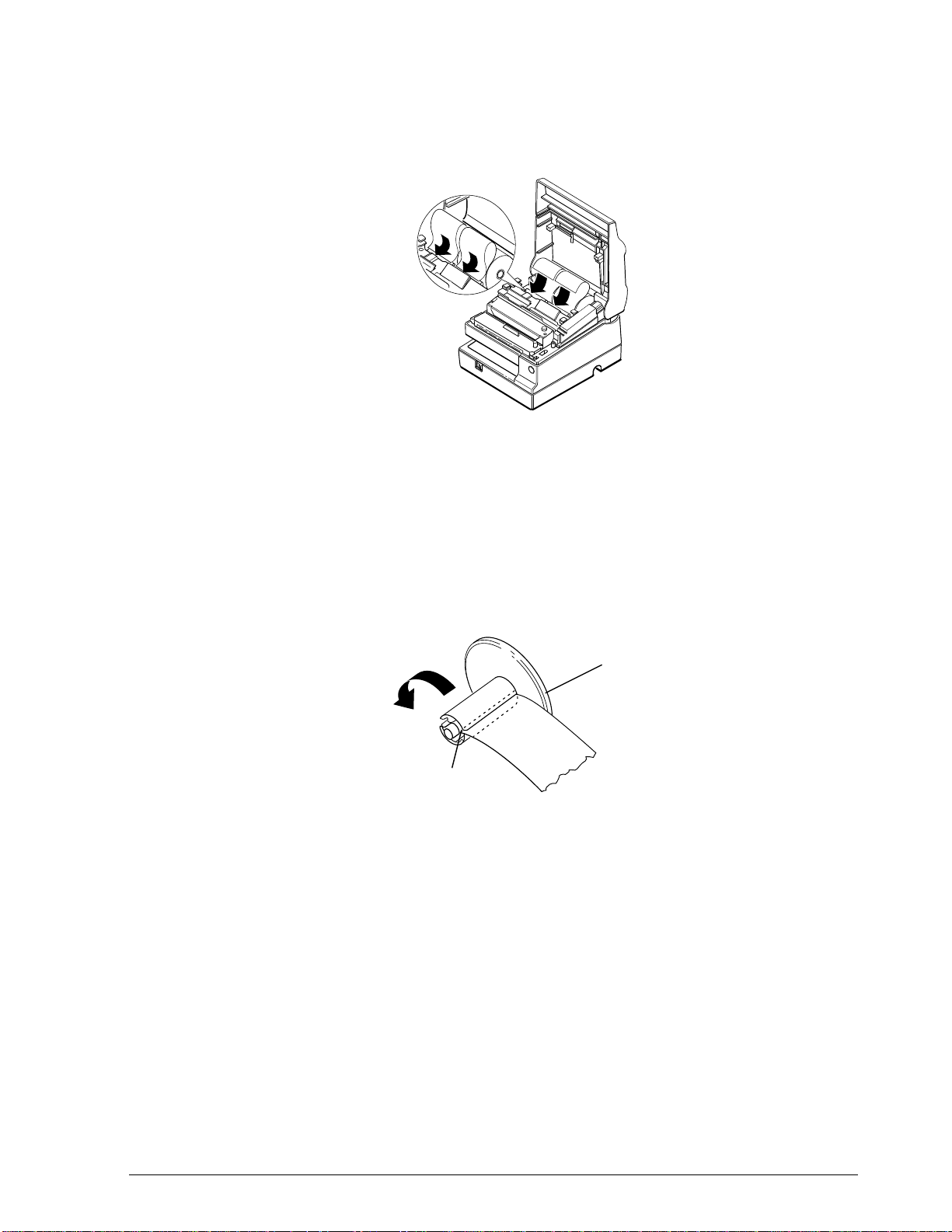
CONFIDENTIAL
4. Insert the tip of the paper from each roll into the corresponding paper inlet. The paper will
automatically be detected and fed into the printer.
5. Tear off the receipt paper on the paper cutter. If the paper was not fed far enough, press the
RECEIPT FEED button to feed additional paper.
TM-U950/U950P Technical Manual
Figure 3-4. Inserting Paper into the Paper Inlet
6. Press the JOURNAL/SLIP FEED button to feed an additional 30 cm (a foot) or so of journal
paper.
7. Insert the tip of the journal paper into the groove on the take-up spool and rotate the spool
two or three times to secure the paper.
Take-up spool
Groove
Figure 3-5.Inserting the Paper into the Spool
Rev. A Handling and Maintenance 3-3
Page 99
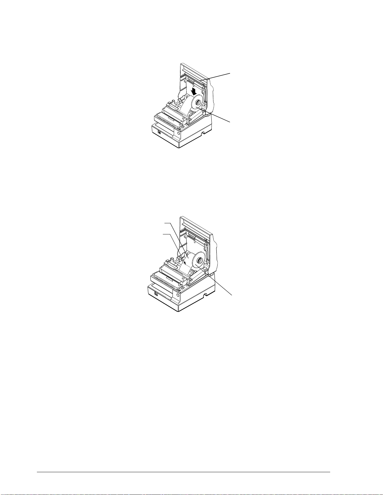
CONFIDENTIAL
8. Install the take-up spool in the printer an d close the prin ter cover.
Removing the Paper Rolls
Printer Cover
Take-up Spool
Figure 3-6. Installing the Spool and
Closing the Printer Cover
1. If you want to remove the paper roll in the journal paper side, cut the journal paper with a
pair of scissors or a knife; then remove the take-up spool.
Journal paper
Cut
Take-up spool
Figure 3-7. Cutting the Journal Paper
3-4 Handling and Maintenance Rev. A
Page 100

CONFIDENTIAL
2. Hold down the paper release lever (marked PRESS) and pull out the paper roll in the
direction of the arrow. As there is a paper release lever on both the receipt and journal sides
of the printer, you can remove either (or both) of the paper ro lls in this way.
TM-U950/U950P Technical Manual
Release Lever
Release Lever
Figure 3-8. Removing the Paper Rolls
Inserting Slip Paper and Printing on Slip Paper
Inserting Slip Paper
Note:
Be sure to install the paper rolls in the printer, even if you plan to print only on slip papers. This will
prevent paper jams. You can also prevent paper jams by using only flat paper, without wrinkles, creases,
or folds.
1. Send ESC c 04 command from the computer, so that the printer enters slip paper mode.
When the printer enters slip paper mode, the SLIP indicator flashes.
Rev. A Handling and Maintenance 3-5
 Loading...