


TM-U950/U950P
Operator’s Manual
MICR Option Included
400485603

Printer parts
DIP switches are on
the bottom
Take-up spool
Power switch
Cover open button
Printer cover
Interface connector
8
1
Display connector
Control panel
POWER
ERROR
RECEIPT
OUT
JOURNAL
OUT
SLIP
RECEIPT
FEED
JOURNAL/
SLIP FEED
Power connector
14 25
1
6
1
13
Drawer connector
2
1
3
TM-U950
TM-U950P
Control panel
POWER
ERROR
RECEIPT
OUT
JOURNAL
OUT
SLIP
RECEIPT
FEED
JOURNAL/
SLIP FEED
POWER light
ERROR light
RECEIPT OUT light
JOURNAL OUT light
SLIP light
RECEIPT FEED button
JOURNAL\SLIP FEED
button

All rights reserved. No part of this publication may be reproduced, stored in a
retrieval system, or transmitted in any form or by any means, mechanical,
photocopying, recording, or otherwise, without the prior written permission of Seiko
Epson Corporation. No patent liability is assumed with respect to the use of the
information contained herein. While every precaution has been taken in the
preparation of this book, Seiko Epson Corporation assumes no responsibility for
errors or omissions. Neither is any liability assumed for damages resulting from the
use of the information contained herein.
Neither Seiko Epson Corporation nor its affiliates shall be liable to the purchaser of
this product or third parties for damages, losses, costs, or expenses incurred by
purchaser or third parties as a result of: accident, misuse, or abuse of this product or
unauthorized modifications, repairs, or alterations to this product, or (excluding the
U.S.) failure to strictly comply with Seiko Epson Corporation’s operating and
maintenance instructions.
Seiko Epson Corporation shall not be liable against any damages or problems arising
from the use of any options or any consumable products other than those designated
as Original Epson Products or Epson Approved Products by Seiko Epson
Corporation.
EPSON is a registered trademark of Seiko Epson Corporation.
ESC/POS is a registered trademark of Seiko Epson Corporation.
NOTICE: The contents of this manual are subject to change without notice.
Copyright © 1995 by Seiko Epson Corporation, Nagano, Japan.
i

Declaration of Conformity
according to ISO/IEC Guide 22 and EN 45014
Manufacturer: SEIKO EPSON CORPORATION
Address: 3-5,Owa 3-chome, Suwa-Shi, Nagano-Ken 392,
Japan
Representative: EPSON EUROPE B.V.
Address: Prof. J.H. Bavincklaan 5
1183 AT Amstelveen,
The Netherlands
Declares that the product
Product Name: Printer
Type Name: M62UA
Conforms to the following Directive and Norms
Directive 89/336/EEC
EN 55022 (1986) Class B
EN 500832-1 (1992)
IEC 801-2 level 2
IEC 801-3 level 2
IEC 801-4 level 2
Directive 90/384/EEC
EN45501: (1992)
June 1995,Type Name+ M62UA Series
M. Hamamoto
President of EPSON \Europe B.V.
ii
Type Name: M62UA Series

Declaration of Conformity
according to ISO/IEC Guide 22 and EN 45014
Manufacturer: SEIKO EPSON CORPORATION
Address: 3-5,Owa 3-chome, Suwa-Shi, Nagano-Ken 392,
Japan
Representative: EPSON EUROPE B.V.
Address: Prof. J.H. Bavincklaan 5
1183 AT Amstelveen,
The Netherlands
Declares that the product
Product Name: Printer
Type Name: M114A
Conforms to the following Directive and Norms
Directive 89/336/EEC
EN 55022 (1986 and 1994 2th) Class B
EN 500832-1 (1992)
IEC 801-2 level 2
IEC 801-3 level 2
IEC 801-4 level 2
Directive 90/384/EEC
EN45501: (1992)
November 1995,
M. Hamamoto
President of EPSON \Europe B.V.
Type Name: M114A
iii

FCC CLASS A
FCC Compliance Statement
For American Users
This equipment has been tested and found to comply with the limits for a Class A
digital device, pursuant to Part 15 of the FCC Rules. These limits are designed to
provide reasonable protection against harmful interference when the equipment is
operated in a commercial environment.
This equipment generates, uses, and can radiate radio frequency energy and, if not
installed and used in accordance with the instruction manual, may cause harmful
interference to radio communications. Operation of this equipment in a residential
area is likely to cause harmful interference, in which case the user will be required to
correct the interference at his own expense.
WARNING
The connection of a non-shielded printer interface cable to this printer will invalidate
the FCC Verification of this device and may cause interference levels which exceed
the limits established by the FCC for this equipment.
You are cautioned that changes or modifications not expressly approved by the
party responsible for compliance could void your authority to operate the
equipment.
FOR CANADIAN USERS
This digital apparatus does not exceed the Class A limits for radio noise emissions
from digital apparatus as set out in the radio interference regulations of the
Canadian Department of Communications.
Le présent appareil numérique n’émet pas de bruits radioélectriques dépassant les
limites applicables aux appareils numériques de Class A prescrites dans le règlement
sur le brouillage radioélectrique édicté par le Ministère des Communications du
Canada.
GERÄUSCHPEGEL
Gemäß der Dritten Verordnung zum Gerätesicherheitsgesetz
(Maschinenlärminformations- Verordnung-3. GSGV) ist der arbeitsplatzbezogene
Geräusch-Emissionswert kleiner als 70 dB(A) (basierend auf ISO 7779).
iv

Introduction
The TM-U950 and TM-U950P are high-quality POS printers that can print on slip,
journal, and receipt paper. The printers have the following features:
❏ Wide slip paper capability (maximum characters per line: 88 with 7 x 9 font).
❏ Interface connector within the printer’s external dimensions.
❏ High throughput using bidirectional, minimum distance printing.
❏ Precision paper feeding at 1/144 inch.
❏ Selectable receive buffer size (32 bytes or 2K bytes).
❏ Slip ejection detector.
❏ Command protocol based on the ESC/POS® standard.
❏ ASB (Automatic Status Back) function that automatically transmits changes in
printer status.
❏ EPSON® intelligent module connection. (For the TM-U950 only.)
❏ EPSON customer display series connection. (For the TM-U950 only.)
❏ Bidirectional parallel interface in accordance with the IEEE 1284 Nibble/Byte
Modes.
❏ Optional Magnetic Ink Character Recognition (MICR) reader that enables the
printer to read and process MICR characters in addition to printing
endorsements. (For the TM-U950 only.)
v
About This Manual
Setting Up and Using
❏ Chapter 1 contains information on unpacking the printer, setting it up, running
the self test, setting the DIP switches, and adjusting the paper near end detector.
❏ Chapter 2 contains information on using the printer, including the optional
MICR reader.
❏ Chapter 3 contains troubleshooting information, including how to clean the
MICR reader.
Reference
❏ Chapter 4 contains specifications.
Notes, Cautions, and Warnings
Note:
Notes have important information and useful tips on the operation of your
printer.
CAUTION:
Cautions must be observed to avoid minor injury to yourself or
damage to your equipment.
WARNING:
Warnings must be followed carefully to avoid serious bodily
injury.
vi

Contents
Chapter 1 Setting Up the Printer
Opening and Closing the Printer Cover . . . . . . . . . . . . . . . . . . . . . . . . . . . . . . . . . . . 1-1
Unpacking . . . . . . . . . . . . . . . . . . . . . . . . . . . . . . . . . . . . . . . . . . . . . . . . . . . . . . . . . . . . 1-2
Removing the protective material . . . . . . . . . . . . . . . . . . . . . . . . . . . . . . . . . . . . 1-2
Connecting the Printer to Your Computer . . . . . . . . . . . . . . . . . . . . . . . . . . . . . . . . . 1-3
TM-U950 . . . . . . . . . . . . . . . . . . . . . . . . . . . . . . . . . . . . . . . . . . . . . . . . . . . . . . . . . 1-3
TM-U950P . . . . . . . . . . . . . . . . . . . . . . . . . . . . . . . . . . . . . . . . . . . . . . . . . . . . . . . . 1-5
Connecting the Printer to the Drawer . . . . . . . . . . . . . . . . . . . . . . . . . . . . . . . . . . . . . 1-5
Connecting to a Direct Connection Display Module . . . . . . . . . . . . . . . . . . . . . . . . 1-9
Grounding the Printer . . . . . . . . . . . . . . . . . . . . . . . . . . . . . . . . . . . . . . . . . . . . . . . . . . 1-10
Connecting the Power Supply . . . . . . . . . . . . . . . . . . . . . . . . . . . . . . . . . . . . . . . . . . . 1-12
Installing the Ribbon Cassette . . . . . . . . . . . . . . . . . . . . . . . . . . . . . . . . . . . . . . . . . . . 1-14
Installing the Paper Rolls . . . . . . . . . . . . . . . . . . . . . . . . . . . . . . . . . . . . . . . . . . . . . . . 1-16
Removing the Paper Rolls . . . . . . . . . . . . . . . . . . . . . . . . . . . . . . . . . . . . . . . . . . . . . . . 1-18
Self Test . . . . . . . . . . . . . . . . . . . . . . . . . . . . . . . . . . . . . . . . . . . . . . . . . . . . . . . . . . . . . . 1-19
Running the self test with roll paper . . . . . . . . . . . . . . . . . . . . . . . . . . . . . . . . . . 1-19
Running the self test with slip paper . . . . . . . . . . . . . . . . . . . . . . . . . . . . . . . . . . 1-20
Setting the DIP Switches . . . . . . . . . . . . . . . . . . . . . . . . . . . . . . . . . . . . . . . . . . . . . . . . 1-20
DIP switch functions . . . . . . . . . . . . . . . . . . . . . . . . . . . . . . . . . . . . . . . . . . . . . . . 1-23
Adjusting the Paper Near End Detectors . . . . . . . . . . . . . . . . . . . . . . . . . . . . . . . . . . 1-26
Using the Power Switch Cover . . . . . . . . . . . . . . . . . . . . . . . . . . . . . . . . . . . . . . . . . . . 1-28
Chapter 2 Using the Printer
Operating the Control Panel . . . . . . . . . . . . . . . . . . . . . . . . . . . . . . . . . . . . . . . . . . . . . 2-1
Buttons . . . . . . . . . . . . . . . . . . . . . . . . . . . . . . . . . . . . . . . . . . . . . . . . . . . . . . . . . . . 2-1
Indicator lights . . . . . . . . . . . . . . . . . . . . . . . . . . . . . . . . . . . . . . . . . . . . . . . . . . . . 2-2
Slip Paper Handling . . . . . . . . . . . . . . . . . . . . . . . . . . . . . . . . . . . . . . . . . . . . . . . . . . . . 2-3
Using the MICR Reader (Option) . . . . . . . . . . . . . . . . . . . . . . . . . . . . . . . . . . . . . . . . . 2-5
Reading MICR characters on personal checks . . . . . . . . . . . . . . . . . . . . . . . . . . . . 2-5
Chapter 3 Troubleshooting
Troubleshooting . . . . . . . . . . . . . . . . . . . . . . . . . . . . . . . . . . . . . . . . . . . . . . . . . . . . . . . 3-1
General problems . . . . . . . . . . . . . . . . . . . . . . . . . . . . . . . . . . . . . . . . . . . . . . . . . . 3-1
Printing problems . . . . . . . . . . . . . . . . . . . . . . . . . . . . . . . . . . . . . . . . . . . . . . . . . . 3-1
Paper handling problems . . . . . . . . . . . . . . . . . . . . . . . . . . . . . . . . . . . . . . . . . . . 3-3
Cleaning the MICR Mechanism . . . . . . . . . . . . . . . . . . . . . . . . . . . . . . . . . . . . . . . . . . 3-7
Hexadecimal Dump . . . . . . . . . . . . . . . . . . . . . . . . . . . . . . . . . . . . . . . . . . . . . . . . . . . . 3-10
vii

Chapter 4 Reference Information
Printing Specifications . . . . . . . . . . . . . . . . . . . . . . . . . . . . . . . . . . . . . . . . . . . . . . . . . . 4-1
Character Specifications . . . . . . . . . . . . . . . . . . . . . . . . . . . . . . . . . . . . . . . . . . . . . . . . 4-2
Ribbon Specifications . . . . . . . . . . . . . . . . . . . . . . . . . . . . . . . . . . . . . . . . . . . . . . . . . . . 4-3
MICR Specifications (Option) . . . . . . . . . . . . . . . . . . . . . . . . . . . . . . . . . . . . . . . . . . . . 4-3
MICR use . . . . . . . . . . . . . . . . . . . . . . . . . . . . . . . . . . . . . . . . . . . . . . . . . . . . . . . . . 4-4
Notes on MICR use . . . . . . . . . . . . . . . . . . . . . . . . . . . . . . . . . . . . . . . . . . . . . . . . 4-4
Paper Specifications . . . . . . . . . . . . . . . . . . . . . . . . . . . . . . . . . . . . . . . . . . . . . . . . . . . . 4-6
viii

Chapter 1
Setting Up the Printer
Opening and Closing the Printer Cover
Use these instructions whenever you need to open or close the
printer.
Open the printer by pushing the cover-open button and then lifting
the printer cover.
Close the printer by pressing on the indentation on the right side of
the printer cover until it audibly clicks into place.
OPEN
CLOSE
1
OPEN
2
Setting Up the Printer 1-1
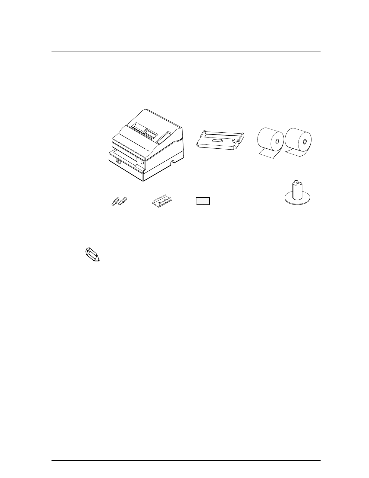
Unpacking
Your printer box should include these items. If any items are
damaged or missing, please contact your dealer for assistance.
Hexagonal lock screws
(only for the TM-U950)
Note:
See the note on page 1-4 for information about the
hexagonal lock screws.
See the power switch cover section in this chapter for
information about the cover.
See the slip paper handling section in Chapter 2 for information
about the label.
Printer
Caution label
Power switch
cover
Ribbon
Keys
Paper rolls
Take-up spool
Removing the protective material
The printer is protected during shipping by a piece of protective
material that must be removed before you turn on the printer.
1-2 Setting Up the Printer
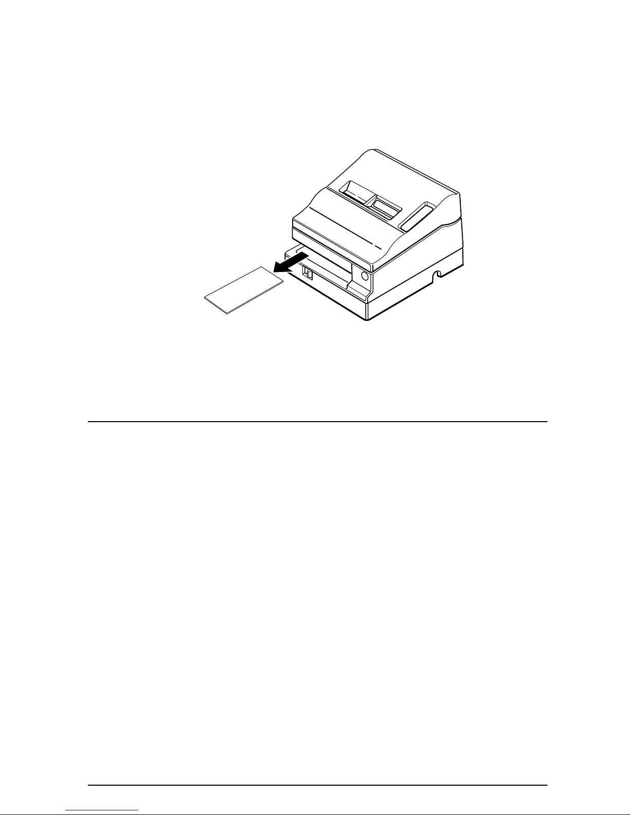
Pull out the protective material and remove it from the printer as
shown below.
Store the protective material with the other packing materials and
use it when transporting your printer.
Connecting the Printer to Your Computer
TM-U950
Follow the procedures below only when you use the printer as a
single unit (not connected to an intelligent module). When you use
the printer with the intelligent module, see the IM-403/405 User's
Guide for details.
You need an appropriate serial interface cable to connect your
computer to the printer's built-in interface.
1. Make sure that both the printer and computer are turned off;
then attach the cable connector securely into the printer's
interface connector.
Setting Up the Printer 1-3
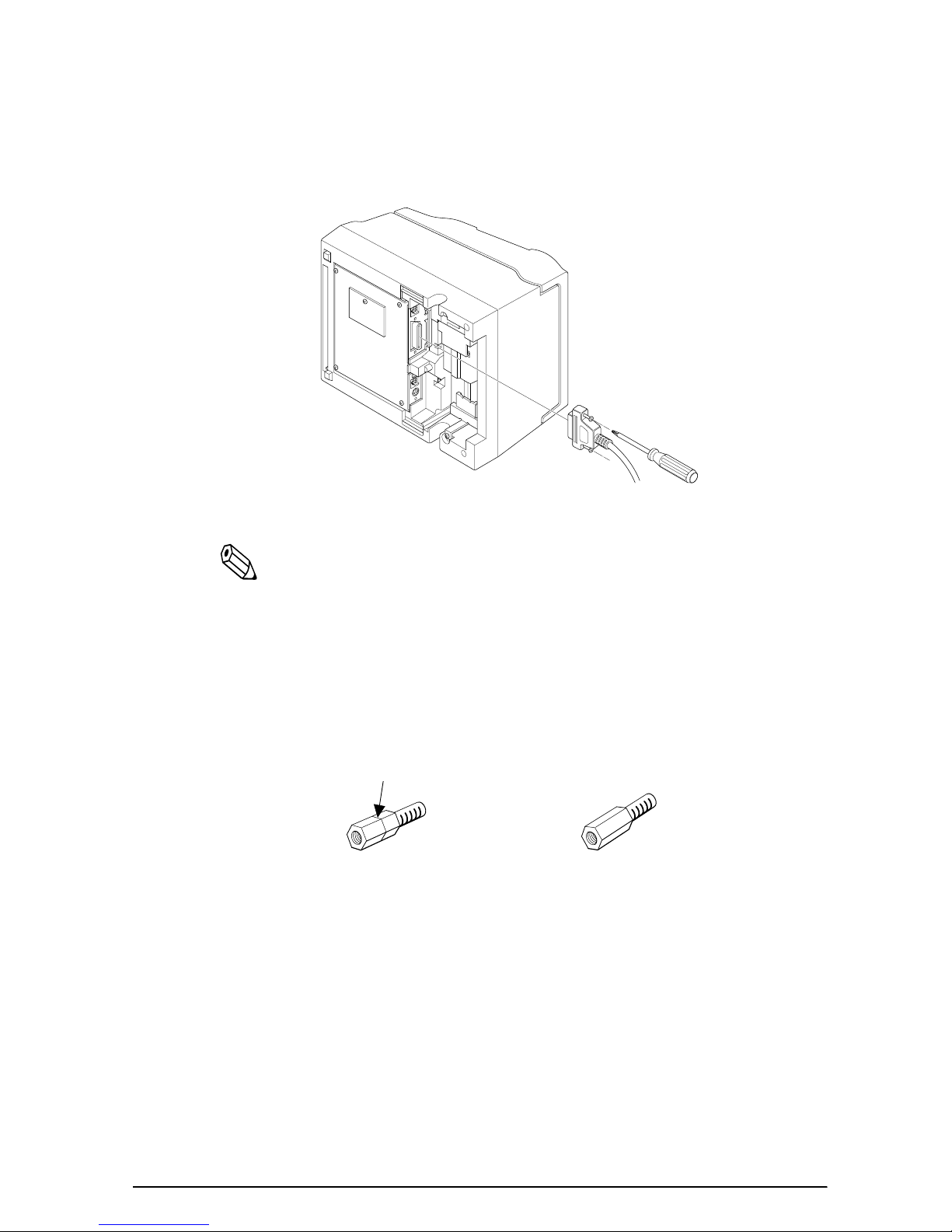
2. Tighten the screws on both sides of the cable connector.
Note:
Your printer comes with inch-type hexagonal lock screws
installed. To use an interface cable that requires millimeter-type
screws, replace the inch-type screws with the enclosed
millimeter-type screws using a hex screwdriver (5 mm).
To distinguish the two types of screws, see the figure below. The
inch-type screw is on the left.
3. Attach the other end of the cable to the computer.
4. Plug the power supply's power cord into an electrical outlet.
1-4 Setting Up the Printer

TM-U950P
You need an appropriate parallel interface cable to connect your
computer to the printer's built-in interface.
1. Make sure that both the printer and computer are turned off;
then attach the cable connector securely into the printer's
interface connector.
2. Attach the other end of the cable to the computer.
3. Plug the power supply's power cord into an electrical outlet.
Connecting the Printer to the Drawer
WARNING:
Use a drawer that matches the printer specification. Using an
improper drawer may damage the drawer as well as the
printer.
Setting Up the Printer 1-5

Follow the procedures below to connect a drawer to the printer
only when you use the printer as a single unit (not connected to an
intelligent module). (Intelligent module connection is available
only for the TM-U950.) When you use the TM-U950 with the
intelligent module, see the IM-403/405 User's Guide for details.
You need an appropriate drawer kick-out cable to connect your
drawer to the printer.
1. Make sure that the printer is turned off.
2. Plug the cable connector into the printer's drawer kick-out
connector until it clicks.
TM-U950
TM-U950P
1-6 Setting Up the Printer

CAUTIONS:
Be sure not to connect this cable to the display module
connector, which is to the left of the interface connector.
Do not connect a telephone line to the drawer kick-out
connector.
Den Drucker an die Lade anschließen
ACHTUNG:
Nur eine Geldlade verwenden, die der Druckerspezifikation
entspricht. Bei Verwendung einer ungeeigneten Geldlade
kann sowohl die Geldlade als auch der Drucker beschädigt
werden.
Verfahren Sie wie im folgenden beschrieben, um eine Geldlade an
den Drucker anzuschließen, aber nur, wenn der Drucker als
Einzeleinheit (nicht angeschlossen an ein intelligentes Modul)
betrieben wird. (Der Anschluß für das intelligente Modul steht nur
beim TM-U950 zur Verfügung.) Einzelheiten betr. Verwendung
des Druckers mit einem intelligenten Modul siehe
Betriebsanleitung der IT-U Serie.
Sie benötigen ein geeignetes Auszug-Verbindungskabel zum
Anschluß der Geldlade an den Drucker.
1. Stellen Sie sicher, daß der Drucker ausgeschaltet ist.
Setting Up the Printer 1-7

2. Stecken Sie den Kabelsteckverbinder fest in den AuszugSteckverbinder am Drucker ein, bis er hörbar einrastet.
TM-U950
TM-U950P
ACHTUNG:
Am Auszug-Steckverbinder für die Geldlade keine
Telefonleitung anschließen.
Nicht den Auszug-Steckverbinder für die Geldlade und den
Displaymodul-Steckverbinder verwechseln.
1-8 Setting Up the Printer

Connecting to a Direct Connection Display Module
(For the TM-U950 Only)
If you are using the printer as a single unit (not connected to an
intelligent module) and you plan to connect a direct connection
display module, follow the steps below. When you use the printer
with the intelligent module, see the IM-403/405 User's Guide for
details.
1. Make sure that the printer is turned off.
2. Plug the cable connector (provided with the direct connection
display module) securely into the printer's display module
connector until it clicks.
CAUTIONS:
Be sure not to connect this cable to the display module
connector, which is to the right of the interface connector.
Do not connect a telephone line to the drawer kick-out
connector.
Setting Up the Printer 1-9

Grounding the Printer
You need a ground wire to ground your printer.
For the TM-U950, if you use the printer as a single unit (not
connected to an intelligent module), you need a ground wire to
ground your printer. Make sure that the wire meets the
specification below.
Thickness of wire: AWG 18 or equivalent
Diameter of terminal to be attached: 3.2
1-10 Setting Up the Printer

1. Make sure that the printer is turned off.
2. Connect the ground wire to the printer using the FG screw on
the bottom of the printer, as shown. For the TM-U950P, you can
use the either FG screw, as shown.
TM-U950
TM-U950P
Setting Up the Printer 1-11
 Loading...