

Page 1

TM-U375/U375P
User’s Manual
400391310
Page 2
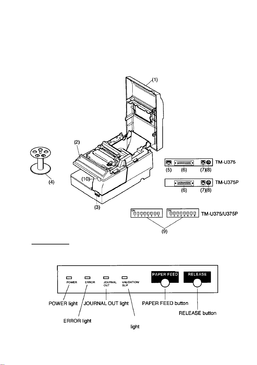
Printer Part Names
Printer cover
(1)
Control panel
(2)
Power switch
(3)
Take-up spool
(4)
Display module connector
(5)
Interface connector
(6)
Drawer kick-out connector
(7)
Power connector
(8)
DIP switches (under a cover)
(9)
Cover open recess
(10)
Control Panel
VALIDATION/SLIP
Page 3

All rights reserved. No part of this publication may be reproduced, stored in a retrieval system,
or transmitted in any form or by any means, electronic, mechanical, photocopying, recording,
or otherwise, without the prior written permission of Seiko Epson Corporation. No patent
liability is assumed with respect to the use of the information contained herein. While every
precaution has been taken in the preparation of this book, Seiko Epson Corporation assumes no
responsibility for errors or omissions. Neither is any liability assumed for damages resulting
from the use of the information contained herein.
Neither Seiko Epson Corporation nor its affiliates shall be liable to the purchaser of this product
or third parties for damages, losses, costs, or expenses incurred by purchaser or third parties as
a result of: accident, misuse, or abuse of this product or unauthorized modifications, repairs, or
alterations to this product, or (excluding the U.S.) failure to strictly comply with Seiko Epson
Corporation’s operating and maintenance instructions.
Seiko Epson Corporation shall not be liable against any damages or problems arising from the
use of any options or any consumable products other than those designated as Original Epson
Products or Epson Approved Products by Seiko Epson Corporation.
EPSON and ESC/POS are registered trademarks of Seiko Epson Corporation in Japan and
other countries/regions.
NOTICE: The contents of this manual are subject to change without notice.
Copyright © 1995 by Seiko Epson Corporation, Nagano, Japan.
i
Page 4

Standards and Approvals
The following standards are applied only to the printers that are so labeled. (EMC is tested using the
Epson power supplies.)
Europe: CE marking
North America: FCC/ICES-003 Class A
Oceania: AS/NZS CISPR22 Class A
WARNING
This is a Class A product. In a domestic environment this product may cause radio interference in
which case the user may be required to take adequate measures.
The connection of a non-shielded printer interface cable to this printer will invalidate the EMC
standards of this device.
You are cautioned that changes or modifications not expressly approved by Seiko Epson Corporation
could void your authority to operate the equipment.
CE marking
The printer conforms to the following Directives and Norms:
Directive 2004/108/EC
FCC Compliance Statement for American Users
This equipment has been tested and found to comply with the limits for a Class A digital device,
pursuant to Part 15 of the FCC Rules. These limits are designed to provide reasonable protection
against harmful interference when the equipment is operated in a commercial environment.
This equipment generates, uses, and can radiate radio frequency energy and, if not installed and used
in accordance with the instruction manual, may cause harmful interference to radio communications.
Operation of this equipment in a residential area is likely to cause harmful interference, in which case
the user will be required to correct the interference at his own expense.
For Canadian Users
This Class A digital apparatus complies with Canadian ICES-003.
À l'intention des utilisateurs canadiens
Cet appareil numérique de classe A est conforme à la norme canadienne NMB-003.
EN 55022 Class A
EN 55024
IEC 61000-4-2 IEC 61000-4-5
IEC 61000-4-3 IEC 61000-4-6
IEC 61000-4-4 IEC 61000-4-11
Restriction of Use
When this product is used for applications requiring high reliability/safety,
such as transportation devices related to aviation, rail, marine, automotive,
etc.; disaster prevention devices; various safety devices, etc.; or functional/
precision devices, etc.; you should use this product only after giving
consideration to including fail-safes and redundancies into your design to
maintain safety and total system reliability. Because this product was not
intended for use in applications requiring extremely high reliability/safety,
such as aerospace equipment, main communication equipment, nuclear power
control equipment, or medical equipment related to direct medical care, etc.,
please make your own judgment on this product’s suitability after a full
evaluation.
ii
Page 5
Introduction
Features
The TM-U375 and
handle slip, validation, and journal printing (both journal and receipt
printing with pressure-sensitive paper) in a single unit. The main features
of the TM-U375 and
0
World’s smallest multi-function 1.5 station printer.
Ci
High-speed printing using logic seeking.
0
Easy problem handling (e.g., paper jams or objects dropped into the
printer) via a clamshell mechanism.
a
Two validation/slip paper entrances: from above for validation paper
and from the front for slip paper.
U Free-format printing in page mode.
Q Various check printing pattern.
Cl
Logic seeking and page mode for check printing.
Ct
Movable platen for easy paper insertion.
Cl
Paper load switch for easy paper roll loading.
Cl
Control capability for two drawers.
a
Selectable character size (7 x 9 font or 5 x 9 font).
Q Command protocol based on the
Q
ASB
(Automatic Status Back) function that automatically transmits
printer status changes.
Q
EPSON® intelligent module connection (for the TM-U375 only).
Cl
EPSON display module series connection (for the TM-U375 only).
Ct
Bidirectional parallel interface in accordance with the IEEE 1284
Nibbe/Byte Modes.
TM-U375P
TM-U375P
are high-performance
printers are as follows:
ESC/POS@
standard.
POS
printers which
About This Manual
Setting up and Using
El
Chapter 1 contains information on unpacking the printer, setting it up,
setting the DIP switches, and adjusting the paper near end detector.
CI
Chapter 2 contains information on using the printer.
LI Chapter
3 contains troubleshooting information.
iii
Page 6
Reference
Cl
Chapter 4 contains specifications.
Notes, Cautions, and Warnings
Note:
0
%
Notes have important information and
of your
printer.
CAUTION:
useful
tips on the operation
Cautions must be observed to avoid minor
yourself or
damage to your equipment.
WARNING:
Warnings
bodily injury.
must be followed carefully to avoid serious
injury
to
iv
Page 7

Contents
Chapter 1 Setting Up the Printer
Unpacking....................................................
Removing the Protective Materials
Downloading Drivers, Utilities, and Manuals .
Connecting the Printer to Your Computer.
Connecting the Printer to Your Drawer.
Anschließen
Connecting the Printer to Your Direct Connection Display Module
Grounding the Printer
Connecting the Power Supply
Installing the Ribbon Cassette
Installing the Paper Roll
Running the Self-test
Setting the DIP Switches
Adjusting the Paper Roll End Sensing Position
Using the Power Switch Cover
des Druckers an Ihre Geldladee
............................................
..........................................
.............................................
Running the self-test with paper roll
Running the self-test with the slip paper
Running the self-test with validation paper.....................
.........................................
TM-U375 DIP-switch functions.
TM-U375P DIP-switch functions
.................................
...........................
...........................
.............................
..........................l-8
(For the TM-U375 only)..........
.....................................
.....................................
..........................
.......................
.............................
.............................
.......................l-23
....................................
l-2
l-2
l-4
l-4
l-6
1-10
l-11
1-12
1-14
1-16
1-18
1-18
1-18
l-19
l-20
l-21
l-22
l-25
Chapter 2 Using the Printer
Operating the Control Panel
Buttons................................................
Indicator lights..........................................
Slip Paper Handling............................................
Validation Paper Handling.......................................
Replacing the Paper Roll........................................
Replacing the Ribbon Cassett
Removing the ribbon cassette. ..............................
Installing the ribbon cassette . .............................
Aerosol sprayer caution . . . . . . . . . . . . . . . . . . . . . . . . . . . . . . . . . 2-9
.....................................
e...................................
.
.
2-2
2-2
2-2
2-4
2-4
2-5
2-6
2-7
2-8
v
Page 8

Chapter
3 Troubleshooting
Troubleshooting................................................
General problems
Printing problems
Paper handling problems
Hexadecimal Dumping.
Starting hexadecimal dumping
Ending hexadecimal dumping
Chapter
Printing Specifications
Character Specifications
Paper Specifications.
Electrical Specifications.
Electrostatic Protection (measured based on the IEC801-2 test conditions) . 4-6
Reliability.
Environmental Specifications
Interface Specifications
Printing on Cut Sheets
Transmit Status Identificationn
Notes On Number of Printable Columns
4 Reference
....................................................
Example print control for cut sheet
.........................................
.........................................
...................................
..........................................
...............................
...............................
Information
...........................................
.........................................
............................................
.........................................
.....................................
..........................................
...........................................
...........................
.....................................
.............................
3-2
3-2
3-2
3-4
3-6
3-6
3-7
4-2
4-2
4-3
4-6
4-6
4-7
4-8
4-8
44-11
4-12
10
vi
Page 9

Chapter
1
Setting Up the Printer
Setting Up the Printer 1-1
Page 10
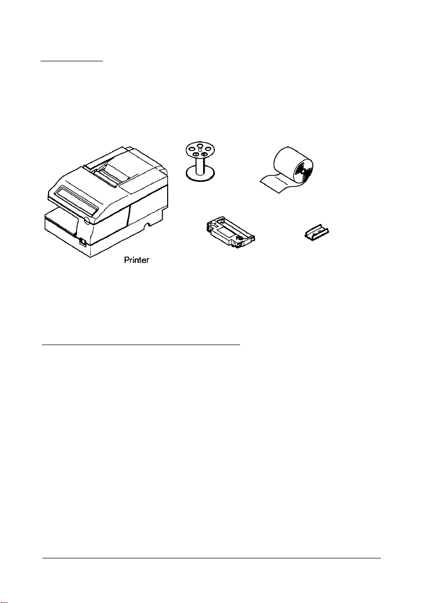
Unpacking
The illustration below shows the items included for the standard
specification printer.
Take-up spool
Ribbon
cassette
Paper roll (1
Power switch cover
Removing the Protective Materials
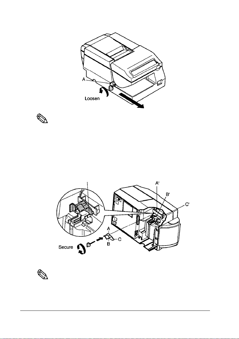
The printer is protected during shipping by protective materials that must
be removed before you turn on the printer.
1.
Loosen the screw and remove the protective material A from the
printer, as the illustration shows on page 1-3.
pc)
1-2
Setting Up the Printer
Page 11
Protective material
Note:
,
%
Store
the steps below.
the
protective material A on the back of
the
printer, following
1.Insert the projections on
corresponding holes as
I
Q&l
Tighten the
2.
Protective material A
Note:
Put
the
ship
or store your printer.
screw.
protective material A back in its original position if you ever
the
protective material A into
the
illustration below.
the
Setting Up the Printer
1-3
Page 12
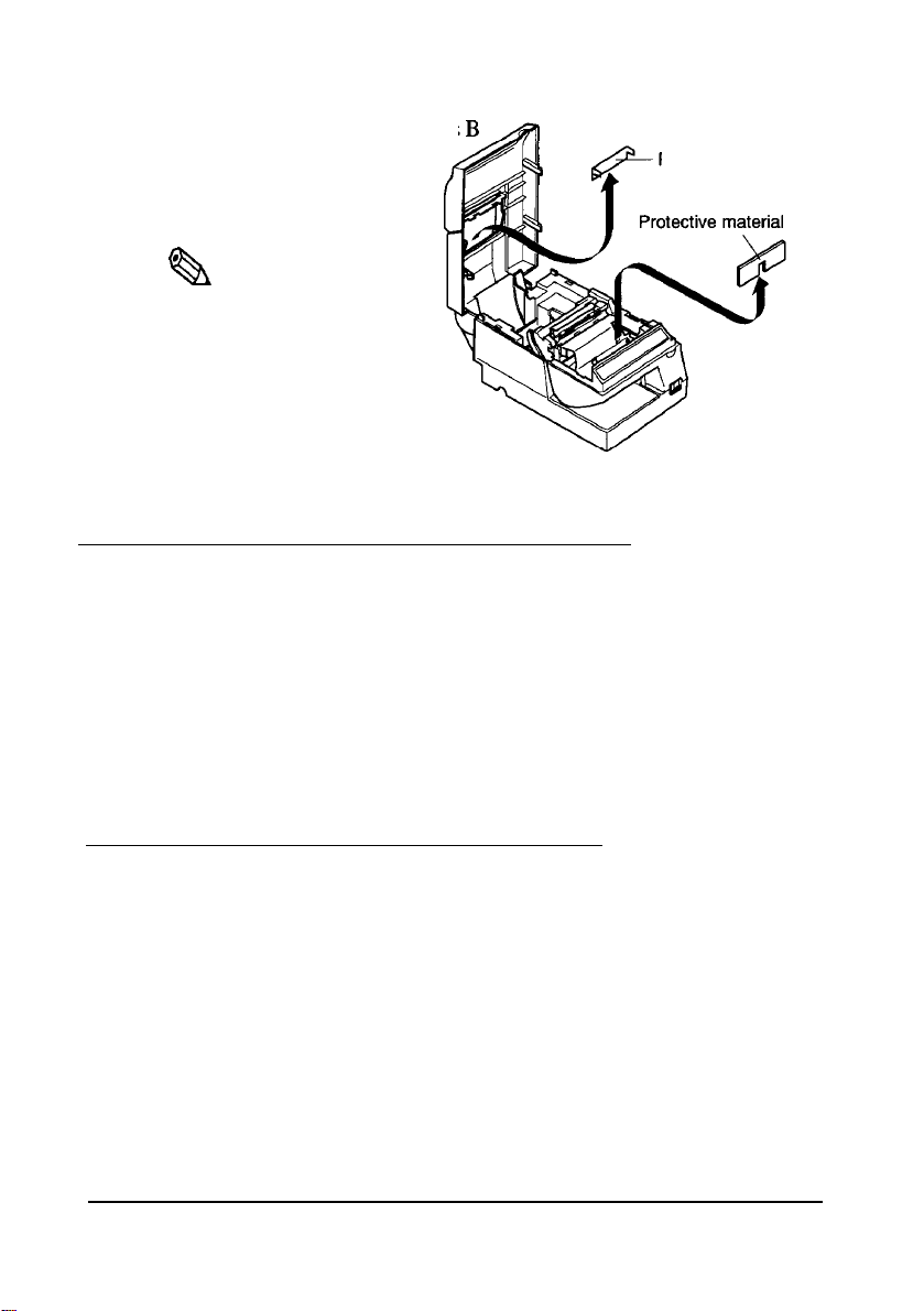
2. Remove the protective materials
and
C
as the illustration.
,
Note:
Qh
Put the protective materials
B and C back in their original
position if you ever ship or
store your printer.
C
Protective material
Downloading Drivers, Utilities, and Manuals
Drivers, utilities, and manuals can be downloaded from one of the following
URLs.
For customers in North America, go to the following web site:
http://www.epsonexpert.com/ and follow the on-screen instructions.
For customers in other countries, go to the following web site:
http://www.epson-pos.com/
B
C
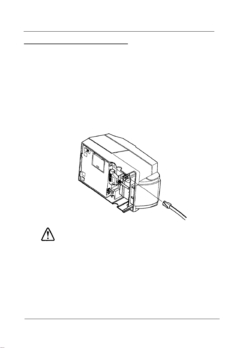
Connecting the Printer to Your Computer
TM-U375
Follow the procedures below only when you use the printer as a single unit
(not connected to an intelligent module). When you use the printer with the
intelligent module, refer to the
You need an appropriate serial interface cable to connect your computer to
the printer’s built-in interface.
1.
Make sure that both the printer and computer are turned off; then plug
the cable connector securely into the printer’s interface connector.
2.
Tighten the screws on both sides of the cable connector.
1-4 Setting Up the Printer
IT-U Series User’s Manual for details.
Page 13
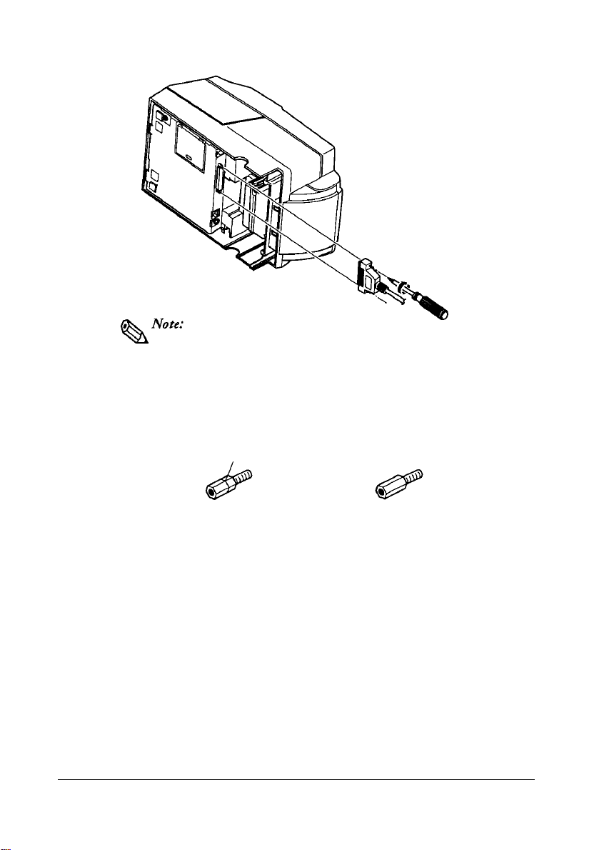
that
screws
requires
Your printer comes with inch-type hexagonal lock
installed.
millimeter-type lock screws, replace the inch-type screws with
the millimeter-type screws by using a hex screwdriver
(5
mm). To distinguish the two types of screws, see the figure
below.
If you
plan to use an interface cable
Notch (one or more lines)
Inch-type
3.
Plug the other end of the cable into the computer.
Millimeter-type
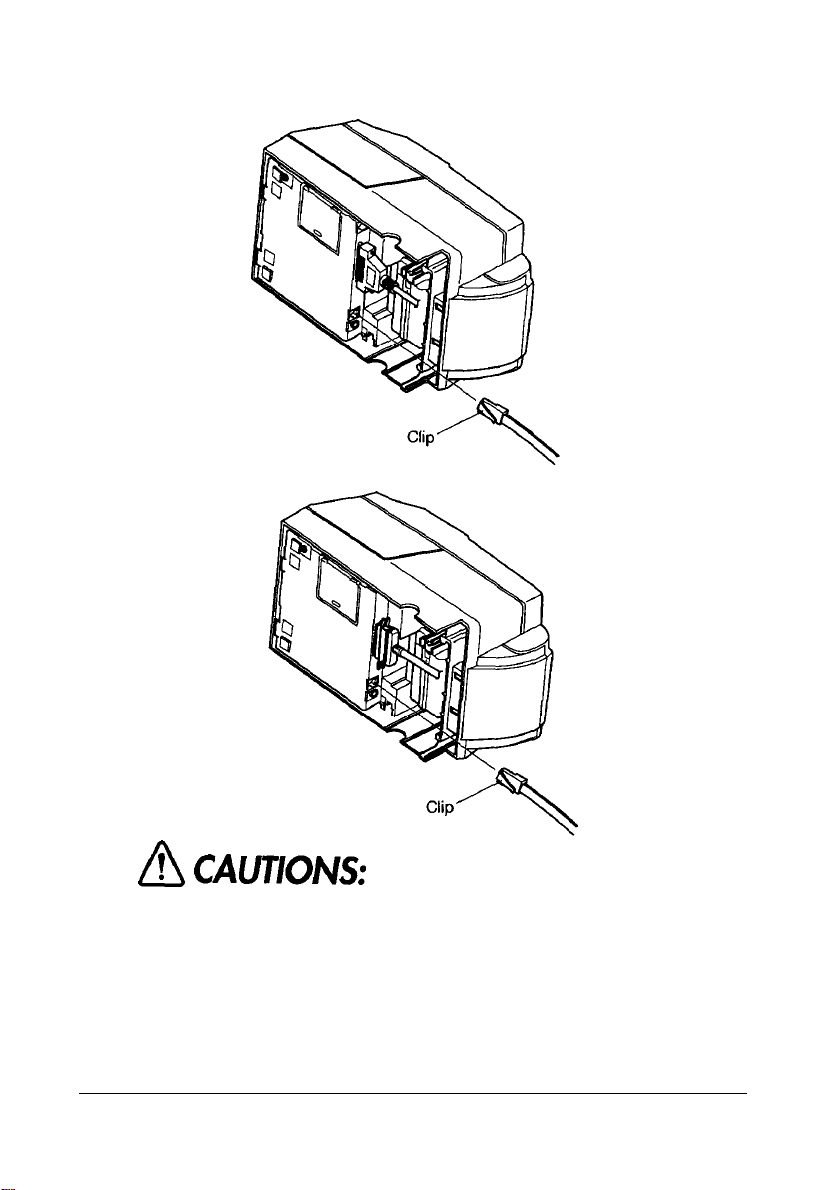
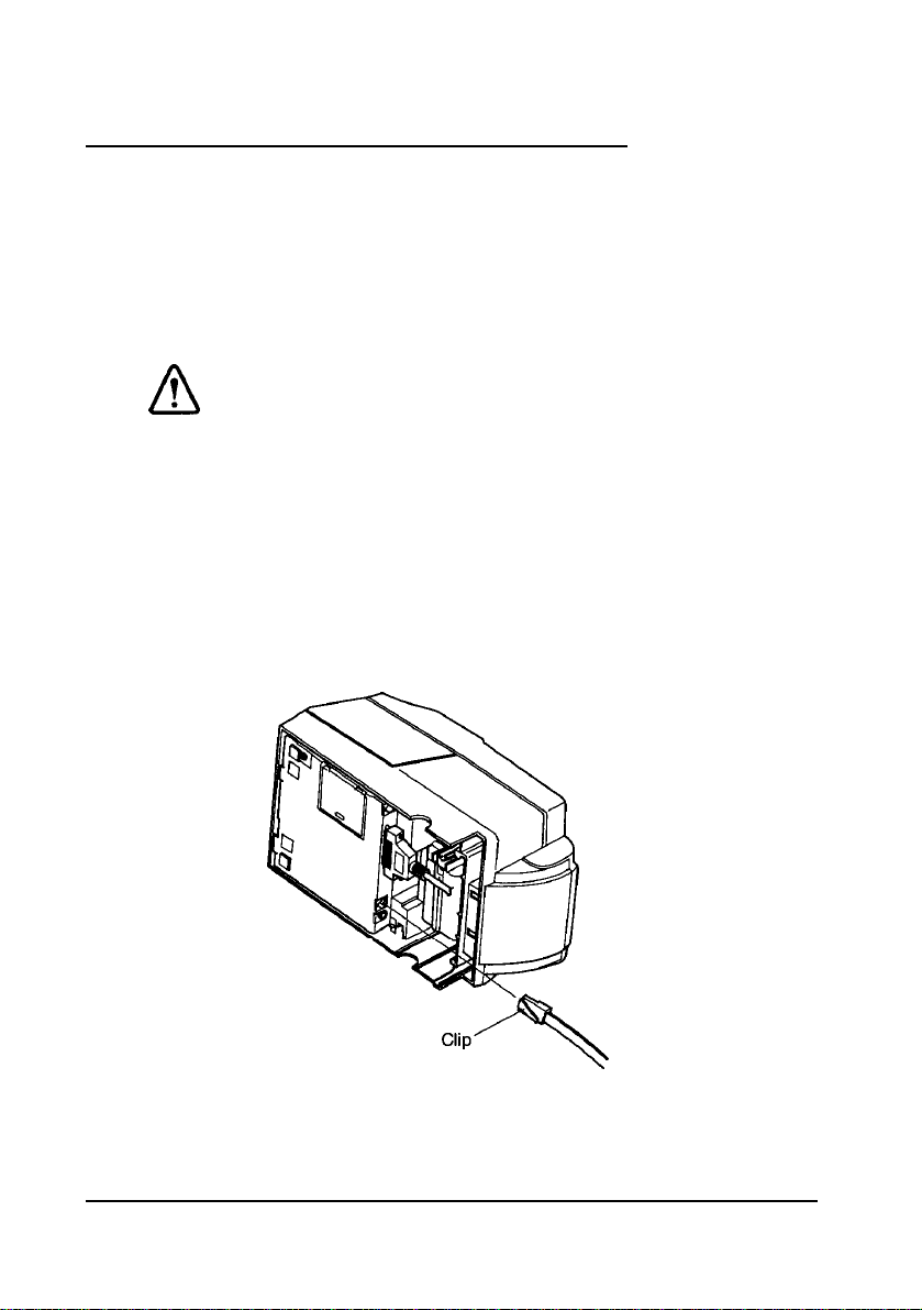
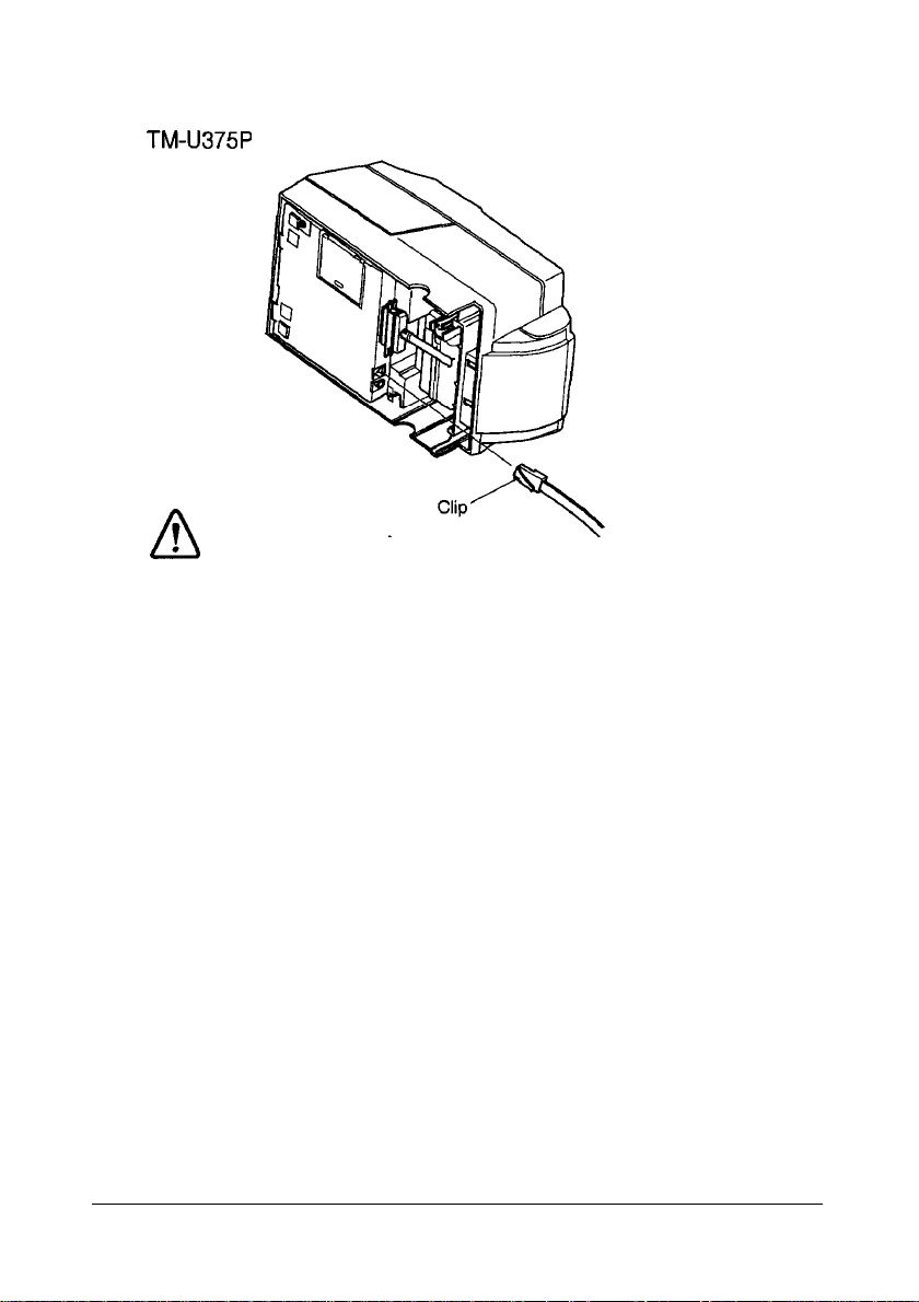
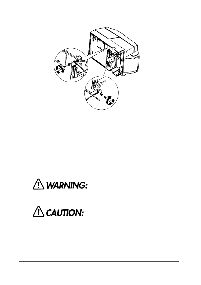
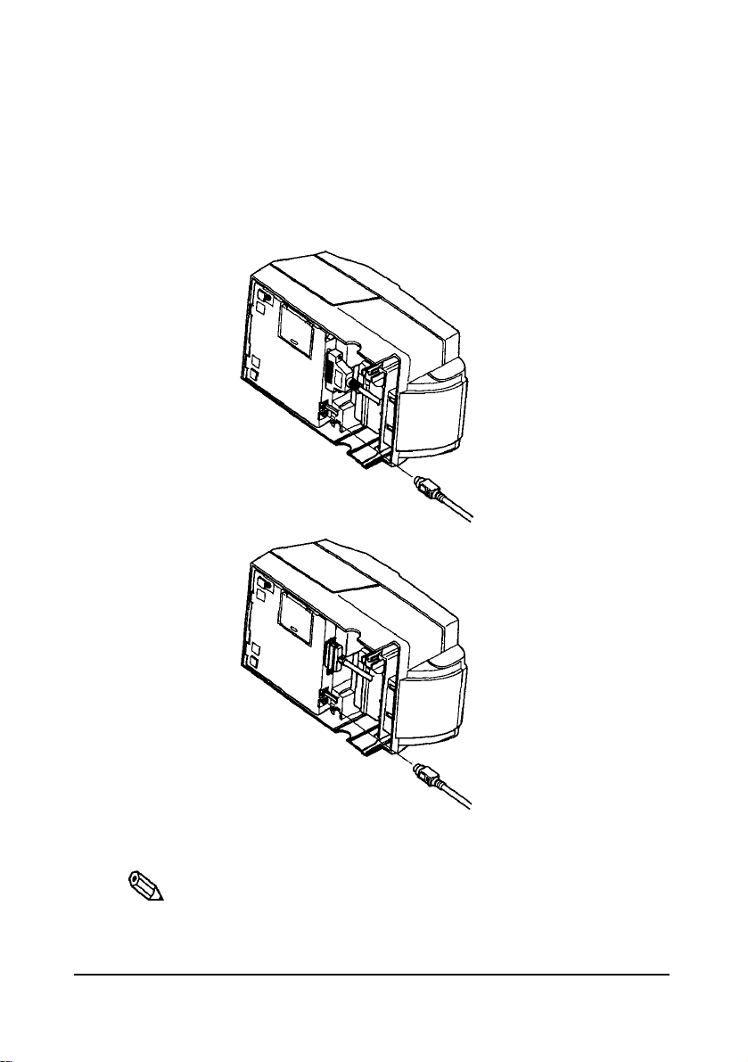
TM-U375P
You need an appropriate parallel interface cable to connect your computer
to the printer.
1.
Make sure that the printer and the computer are turned off.
Then plug the cable into the connector on the printer, as shown.
Setting Up the Printer 1-5
Page 14

Note:
*
%A
Squeeze the wire clips on the printer
place on
2.
Connect the other end of the cable to the connector on your computer.
both
sides of
the
connector.
together
until
they
Connecting the Printer to Your Drawer
Follow the procedures below to connect a drawer to the printer only when
you use the printer as a single unit (not connected to an intelligent module).
(Intelligent module connection is available only for the TM-U375.) When
you use the TM-U375 with the intelligent module, refer to the
User’s Manual
1.
Make sure that the printer is turned off.
2.
Plug the cable connector securely into the printer’s drawer kick-out
connector until it clicks.
for details.
Use
a drawer
Using an
well as
the
that
improper
printer.
matches the
drawer
may damage the drawer as
printer
specification.
lock in
IT-U Series
1-6 Setting Up the Printer
Page 15
TM-U375
TM-U375P
A CAUTIONS:
1.
Do
2.
not connect
out
connector.
Do
not
confuse the drawer
the
display
a telephone
module connector.
line
to
the drawer kick
kick
out connector and
Setting Up the Printer
1-7
Page 16
Anschließen des Druckers
an
lhre Geldlade
Verfahren
Drucker anzuschließen,
angeschlossen an ein intelligentes Modul) betrieben
betr. Verwendung
Betriebsanleitung der IT-U
A
1.
2.
TM-U375
Sie wie
im folgenden beschrieben, um eine Geldlade an den
aber
nur, wenn der Drucker
des
Druckers mit einem intelligenten Modul siehe
Serie.
ACHTUNG:
Nur
eine
Geldlade verwenden,
Druckerspezifikation
ungeeigne ten Geldlade
such
der Drucker beschäaligt werden.
Stellen
Sie
sicher,
Stecken
Steckverbinder am Drucker ein, bis er hörbar einrastet.
Sie
daß
den Kabelsteckverbinder fest in den Auszug-
entsprich t. Bei
kann
der Drucker ausgeschaltet
die
der
Verwendung einer
sowohl
als
Einzeleinheit (nicht
wird.
Einzelheiten
die
Geldlade
ist.
als
1-8
Setting Up the Printer
Page 17
TM-U375P
A
ACHTUNG:
1.
Am Auszug-Steckverbinder
Telefonleitung anschließen.
N
icht den Auszug-Steckverbinder für die Geldlade
2.
und
für die
den
Displaymodul-Steckverbinder vetwechseln.
Geldlade
keine
Setting Up the Printer
1-9
Page 18
Connecting the Printer to Your Direct Connection Display
Module (For the
Follow the procedures below to connect a direct connection display
module to the printer only when you use the printer as a single unit (not
connected to an intelligent module). When you use the printer with the
intelligent module, refer to the
1.
Make sure that the printer is turned off.
2.
Plug the cable connector (provided with the direct connection display
module) securely into the printer’s display module connector until it
clicks.
TM-U375
TM-U375
only)
IT-U Series User’s Manual for details.
A
CAUTIONS:
1.
Do
not
connect a telephone
out
connector.
2.
Do
not
confuse the drawer
display
the
3.
Never connect any
module to the DM connector.
4.If you connect
module to the DM connector,
Corporation
product
1-10 Setting Up the Printer
module connector.
product other
any product
is not liable for any
or to the
TM-U375 itself.
line
to the drawer
kick out connector
than the
other than the
Seiko
Epson
damage to the other
display
display
kick
and
Page 19
Grounding the Printer
When you use the printer as a single unit (not connected to an intelligent
module), you need to ground your printer. (Intelligent module connection
is available for the TM-U375 only.)
Recommended wire is described below.
Thickness of wire
Diameter of terminal to be attached
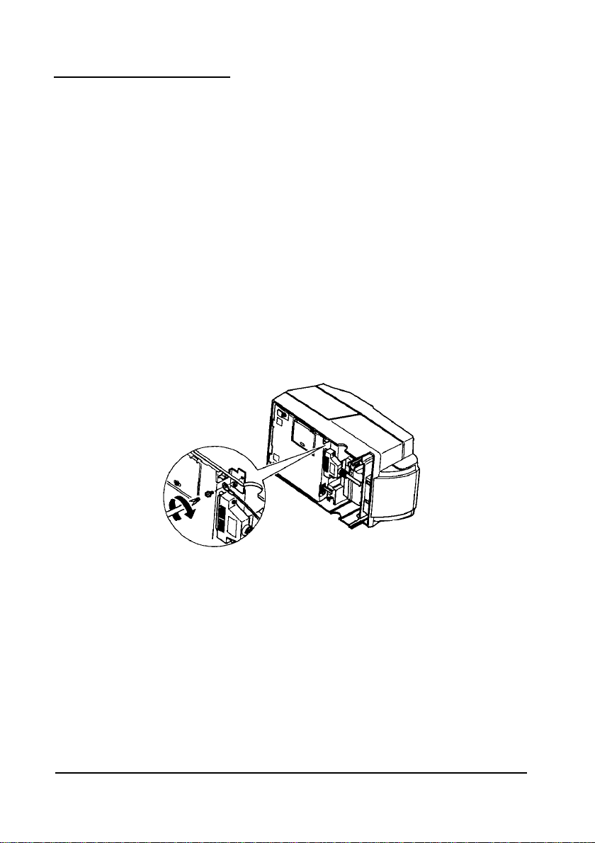
1.
Make sure that the printer is turned off.
2.
Connect the ground wire to the ground connector (marked FG) on the
bottom of the printer with the screw provided on the printer.
Alternatively, another screw located beside the power connector on the
TM-U375P can be used to connect the ground wire.
TM-U375
: AWG18
:
or equivalent
3.2
Setting Up the Printer
1-11
Page 20
TM-U375P
3.
Ground the other end of the ground wire.
Connecting the Power Supply
When the printer is used as a single unit, not connected to an intelligent
module, use the specified EPSON power supply for your printer.
When the printer is connected to an intelligent module, the power is
supplied by the intelligent module. Refer to
for details. (Intelligent module connection is available for the TM-U375
only.)
the IT-U Series User’s Manual
1-12
Using an
electrical
When
from the printer,
plugged
damage the
1.
Make sure that the printer’s power switch is turned off, and that the
power supply’s power cord is unplugged from the electrical outlet.
Setting Up the Printer
incorrect
shock.
connecting or disconnecting the
in
to an electrical outlet; otherwise
power supply
make sure that
power
supply or the
may
the
printer.
cause fire
power
power
supply is not
you
or
supply
may
Page 21
2.
Check the label on the power supply to make sure that the required
voltage matches that of your electrical outlet.
3.
Plug the power supply’s DC cable connector into the printer’s power
connector as shown below.
TM-U375
TM-U375P
4.
Plug the power supply’s power cord into an electrical outlet.
,
Note:
Qh
To
remove
the DC
and pull it
cord is unplugged before you disconnect the DC cable connector.
straight
cable
connector, grasp
out. Make sure
the
connector at the arrow
that the
power
Setting Up the Printer
supply 's
power
1-13
Page 22

Installing
A
the Ribbon Cassette
CAUTIONS:
Never
direction of the arrow marked on the cassette; otherwise
the ribbon cassette may be damaged.
turn
the ribbon
cassette’s
knob in the opposite
Be sure
replace a
Note:
*
%
Use
1.
Turn on the printer and open the printer cover.
2.
Turn the ribbon cassette’s knob two or three times in the direction of the
arrow, to take up any slack in the ribbon.
3.
Insert the ribbon in the position as the illustration below and push the
ribbon cassette until it clicks. Then rotate the cassette’s knob two or
three more times. This is necessary to place the ribbon in the correct
position.
the printer is
ribbon
the
EPSON ERC-38 ribbon cassette for your printer.
not
receiving
cassette; otherwise
data when you
3
times
data may
be
lost.
1-14
Setting Up the Printer
Page 23

or 3more times
2
Knob
4.
Make sure that the ribbon is installed between the print head and the
ribbon mask without wrinkles or creases, as shown below.
Print head
*
Note:
Q3.l
If
the
ribbon is not installed
grasp
the
cassette's tab on
then
pull
the
cassette out of
above to install
the
ribbon cassette again.
correctly,
the
left side,
the
to remove
lift the left
printer.
the
side out first, and
Repeat steps
ribbon cassette,
2,
3 and
4
Tab
Setting Up the Printer
1-15
Page 24

Installing
the Paper Roll
Use a paper roll that matches the specifications.
Note:
,
Q3
The
printer must be turned on before installing
1.
Fold the paper so it is exactly straight and even, as shown in the
illustration, and will not tear off jaggedly.
No
2.
Turn on the printer, open the printer cover, and remove the take-up
3.
Insert the paper roll as shown below.
No
the
Correct
paper roll.
spool.
1-16
4.
Insert the tip of the paper into the paper inlet as far as it will go, and
push the PAPER LOAD switch
to feed the paper roll until the paper
comes out from the top of the printer.
Note that the arrow in the exploded drawing below points towards the
front of the printer.
Setting Up the Printer
Page 25

Paper inlet
PAPER LOAD switch
5.
When using the take-up spool, follow the steps and the illustration
below.
a)
Pull out the side of the take-up spool and insert the tip of the paper
roll into the groove on the spool as the illustration below.
b)
Rotate the spool two or three times to secure the paper and reinsert
the side of the take-up spool as the illustration below.
2 or
c)
Install
6.
Tear off the receipt paper on the cutter; then close the printer cover.
,
%
Note:
When the
inactive.
the
take-up spool in the printer.
printer cover is open,
the
PAPER FEED
Setting Up the Printer
button is
1-17
Page 26

Running the Self-test
Any time that you want to check the performance of your printer you can
run the self test described below. This shows whether your printer is
working correctly. It is independent of any other equipment or software.
You can run the self-test with the paper roll, slip paper, or validation paper.
Running the self-test with paper roll
,
Note:
Qh
Be sure to install
run
the
self test.
1.
Make sure the printer is turned off and the printer cover is closed properly.
2.
While holding down
begin the self-test. The self-test prints the printer settings and pauses
printing. (The JOURNAL OUT light flashes.)
3.
Press the PAPER FEED button to continue printing. The self-test
prints some lines of characters from the character table.
4. The self-test automatically ends after printing
the paper. The printer becomes ready to receive data from the computer
after the self-test.
5.
Self-test mode switches to normal mode.
the
ribbon cassette and
the
PAPER FEED button, turn on the printer to
the
paper roll before you
"***
completed
***"
on
Running the self-test with the slip paper
Note:
.
%
Be sure to install
1.
Make sure the printer is turned off and the printer cover is closed
properly.
2.Hold down the RELEASE button and turn on the printer to begin the
self-test. The VALIDATION/SLIP light flashes.
3.
Feed a sheet of slip paper into the printer. The self-test loads the paper
automatically, prints the printer settings, and then ejects the paper. The
VALIDATION/SLIP light flashes.
4.
Remove the paper and feed another sheet of slip paper into the printer
to print characters from the character table. Continue to feed slip paper
into the printer until
1-18
Setting Up the Printer
the
paper roll in
the
self-test prints
the
printer to prevent
"***
completed
slip
paper jams.
***".
Page 27

5.
The self-test automatically ends after printing
The printer is ready to receive data from the computer after the self-test
completes.
6. Self-test mode switches to normal mode.
"***
completed
Running the self-test with validation paper
Note:
,
Qa
Be sure to install
paper jams.
1.
Make sure the printer is turned off and the printer cover is closed
properly.
2.
Hold down the PAPER FEED and RELEASE buttons and turn on the
printer to begin the self-test. The VALIDATION/SLIP light flashes.
3.
Feed a sheet of validation paper into the printer. The self-test prints the
printer settings, and then ejects the paper. The VALIDATION/SLIP
light flashes.
4.
Remove the paper and feed another sheet of validation paper into the
printer to print characters from the character table. Continue to feed
validation paper into
***".
5.
The self-test automatically ends after printing
The printer is ready to receive data from the computer after the self-test
completes.
6.
Self-test mode switches to normal mode.
the
paper roll in
the
printer until the self-test prints
the
printer to prevent validation
"***
completed
"***
completed
***".
***".
Note:
,
%
If
you want to pause
validation paper at any point, press
the
PAPER FEED button again to resume
the
self-test for
the
paper roll, slip paper, or
the
PAPER FEED button. Press
the
self-test.
Setting Up the Printer
1-19
Page 28

Setting the DIP Switches
Turn off
to prevent an
printer.
You can change your interface and print column settings by changing
DIP switch settings.
1. Make sure the printer is turned off.
2.
Remove the screw from the DIP switch cover. Then take off the DIP
switch cover, as shown in the illustration below.
3.
There are two sets of switches. Notice that ON is marked on each set of
switches. Use tweezers or another narrow tool to move the switches.
the printer
electrical short,
while
removing the DIP switch cover
which
can damage the
the
1-20
4.
Use the following tables to set the DIP switches. Numbers starting with
1 are in the first set, and numbers starting with 2 are in the second.
Setting Up the Printer
Page 29

TM-U375 DIP-switch functions
DIP Switch Set 1
SW Function
l-1 Data reception error
Receive buffer capacity
l-2
l-3 Handshaking
l-4Word length
Parity check
1-5
Parity selection
l-6
Transfer speed (see table below)
l-7
l-8 Transfer speed (see table below)
ON
Ignored
40
bytes
XON/XOFF
7 bits
Yes
Even
OFF
'?
Prints
4K
bytes
DTR/DSR
8 bits
No
Odd
'
Transfer Speed (BPS)
1200
2400
4800
9600
BPS: Bits Per Second
DSW2
SW
2-l Connection of display module
2-2
2-3
2-4
2-5
2-6
2-7
2-8
Function
(see Note 1 on the next page)
Selects number of characters
per line
(CPL)
7 X 9 font/5 X 9 font
(refer to the
Handshaking operation
(busy condition)
For internal use only.
For internal use only.
For internal use only.
Pin 6 reset signal
(see Note 2 on the next page)
Pin 25 reset signal
(see Note 2 on the next page)
Notes on Number
of
SW7
ON
OFF
ON
OFF
ON
Connected
42
CPL/
35 CPL
Printable Columns
Receive
buffer full receive buffer full
Used
Used
SW8
ON
ON
OFF
OFF
OFF
Not connected
40 CPU
33
section in Chapter
Off-line or
Not used
Not used
CPL
4)
Do
not
change the settings of switch
2-4, 2-5
Setting Up the Printer
and
2-6.
1-21
Page 30

Notes:
*
Qh
1.
This function can be used only when a direct connection display
module is connected to the display module connector.
2..
DIP switch settings cannot be changed after the power is turned
on or
after
the printer is reset through the interface.
turning
7 and 8.
the
power on, do not change
TM-U375P DIP-switch functions
DIP Switch Set 1
SW Function
1-1 Auto line feed
l-2 Receive buffer capacity
l-3 Undefined
l-4 Undefined
1-5 Undefined
1-6
Undefined
l-7 Undefined
l-8 Undefined
DIP Switch Set 2
SW
2-
1 Undefined
2-2 Print column selection
2-3 Handshaking (busy condition)
2-4 Reserved.
2-5
2-6
2-7 Undefined
2-8
Function
7
X
9 font/9 X 9 font
Settings must not be changed.
Settings must not be changed.
nInit reset signal Fixed to ON.
the
settings of DIP
ON
Enabled
40 bytes
ON OFF
42CPL/35CPL
Receive
buffer full
When
switches
OFF
Disabled
4K
bytes
40CPL/33CPL
Off-line or
receive buffer full
A CAUTION:
Do
not
change the settings of switch
5.
Replace
1-22 Setting
the
DIP switch cover and secure it
Up
the Printer
2-4, 2-5, 2-6 and 2-8.
with
the screw.
Page 31

,
Note:
%h
To
attach the
the
cover
DIP switch cover, insert
leftward,
as
shown
in
the
cover upward
the
illustration below.
then
Adjusting the Paper Roll End Sensing Position
The paper near end detector detects when the paper is almost gone by
measuring the diameter of the paper roll. Software programs can use the
ESC
c
4 command to stop printing when the paper is almost gone.
If you want to change the amount of paper remaining when the printer
stops printing, follow the steps below to adjust the paper near end detector.
slide
,%Note:
If
the
inner diameter of
inch),
the
paper roll near-end detector may not work properly.
1. Open the printer cover and remove the take-up spool.
2.
Determine the point on the paper roll at which you want the near-end
detector to be triggered. Then measure the distance A shown in the
illustration.
the
paper roll core is less
Setting Up the Printer
than
10 mm
(0.39
1-23
Page 32

Distance A
*
Notes:
a
There may be some difference between
and
the
actual sensing position.
3.
Find the corresponding adjustment position number from
the
measured distance A
the
table below.
Distance A
10 mm (0.39 inch)
8 mm (0.32 inch)
6 mm (0.24 inch)
4
mm (0.16 inch)
2
mm (0.08 inch)
4.
Loosen the detector screw with a coin or screwdriver.
5.
Set the detector scale to the position you determined from the table by
moving the detector screw up or down. The numbers
not marked on
Detector scale
#l
the
detector scale. Use the illustration below for reference.
Adjustment position number
#2
#3
#4
#5
#1, #2, #3...
Detector scale
are
1-24
6.
Secure the detector screw; then replace the take-up spool and close the
printer cover.
Setting Up the Printer
Page 33

Using
the
Power Switch Cover
You can use the provided power switch cover to protect the power switch
from accidental or improper operation. Attach the cover as shown in the
illustration below.
You can turn the power on or off with the switch cover attached by
inserting a pointed object (like a ball point pen) through either of the two
small holes on the switch cover.
Push to attach the cover.
If an accident
attached, unplug the
immediately.
occurs
when
the
power
power supply
Setting Up the Printer
switch cover
cord
from
is
the outlet
1-25
Page 34

Page 35

Chapter 2
Using the Printer
Using the Printer
2-1
Page 36

Operating the Control Panel
The control panel has two buttons and four lights.
Buttons
The control panel buttons perform paper feeding and release functions.
PAPER FEED
Press the PAPER FEED button once to advance paper one line. You can
also press the
PAPER FEED
button continuously to feed the paper continuously.
RELEASE
Press
the
RELEASE button to release the paper clamp.
lndicator lights
The control panel lights provide information on printer conditions.
POWER (green)
The POWER light is on when the printer power is on.
ERROR (red)
The
ERROR
light is on or is flashing when the printer is not ready to print.
The ERROR light is on under the following conditions:
l
When you first turn on the printer or after you reset the printer using the
interface. The ERROR light goes off after the printer is initialized.
l
When the printer cover is open. Close the printer cover if this is the case.
l When the printer stops printing because it senses the paper roll end.
Install a new paper roll if this is the case.
2-2 Using the Printer
Page 37

Page 38

Slip
Paper Handling
Use only slip paper (flat paper without wrinkles, creases, or folds) that
matches the specifications.
Note:
I
Qh
Be sure to install the paper
print only on slip paper. This will prevent paper jams.
1.
Send the appropriate control commands from the computer to print on
slip paper.
2.
When the VALIDATION/SLIP light flashes, insert a slip into the slip
paper inlet as shown in the illustration below.
Make sure you insert the slip paper into the inlet as far as it will go.
roll
in the printer, even if you plan to
3.
The paper will automatically be drawn in and printing will begin.
Note:
,
a
When the
application software), remove the paper from
VALIDATION/SLIP
light
flashes
(this depends
the
paper
Validation Paper Handling
Use only validation paper (flat paper, without wrinkles, creases, or folds)
that matches the specifications.
Note:
,
%
Be sure to install
print only on validation paper.
2-4 Using the Printer
the
paper roll in
the
printer, even
This
will prevent paper jams.
on the
path.
if
you plan to
Page 39

1. Send the appropriate control commands from the computer to print on
validation paper.
2.When the VALIDATION/SLIP light flashes, insert a sheet of validation
paper into the validation paper inlet (see the illustration below);
printing will then begin.
Make sure you insert
*
Note:
Qb
When the
application software), remove
VALIDATION/SLIP light flashes (this depends on the
the
validation paper into the inlet as far as it will go.
Replacing the Paper Roll
To change the paper roll, follow the steps below.
1.
Cut the journal paper on the cutter; then remove the take-up spool.
the
paper from
the
paper
path.
Using the Printer 2-5
Page 40

2.
Pull out the paper roll and cut the paper, as the illustration below.
3.
Press the PAPER LOAD switch and remove the paper in the direction
of the arrow, as the illustration below.
LOAD switch
PAPER
Never pull
4.
Reinstall a new paper roll by following the steps in
Roll
in Chapter 1.
out
the
paper roll manually.
Replacing the Ribbon Cassette
Never
opposite direction of the arrow marked on the cassette;
otherwise the ribbon cassette may be damaged.
Be sure the printer
replace a ribbon cassette; otherwise
Note:
,
Qh
Use
2-6 Using the Printer
turn the
the
EPSON-ERC-38 ribbon cassette for your printer.
ribbon cassette’s feed
is not
receiving data when
Installing
knob in the
you
data
may be
the Paper
lost.
Page 41

,
Note:
Qsh
There
are two ways to replace
printer off and on again before installing or removing
cassette, making sure
(When
you turn off
is lost.) The
other
that
the
printer power, data sent from
is to open
the
data
sent
the
printer cover and press
RELEASE button before installing or removing
Both
ways cause
and
the
paper clamp to release. If one of
ribbon
might
the
print head to move to
not be inserted or removed correctly.
Removing the ribbon cassette
1.
Turn the printer power off and on again; then open the printer cover.
2.
Grasp the ribbon cassette’s tab on the left side, lift the left side out first,
and then pull the cassette out of the printer, as shown in the illustration below.
ribbon cassette. One is to turn
the
ribbon
from
the
computer is not lost.
the
computer
the
the
ribbon cassette.
the
center of
these
ways is not used,
the
printer
the
the
Tab-
Using the Printer
2-7
Page 42

Installing the ribbon cassette
1.
Turn the ribbon cassette’s knob two or three times in the direction of the
any
arrow, to take up
2.
Insert the ribbon in the position as shown below, and push the ribbon
cassette into the printer until it clicks. Then rotate the cassette’s knob
two or three more times. This is necessary to place the ribbon in the
correct position.
slack in the ribbon.
or 3 times
Using the Printer
2-8
Page 43

3.
Make sure that the ribbon is installed between the print head and the
ribbon mask without wrinkles or creases, as shown below.
Print head
*
Note:
a
Remove
printer for a long time.
CAUTION:
Do not use aerosol sprayers containing flammable gas
inside or around this product. Doing so may cause fire.
the
ribbon cassette from the printer when you store the
Using the Printer 2-9
Page 44

Page 45

Chapter 3
Troubleshooting
Troubleshooting 3-1
Page 46

Troubleshooting
Read this section if you have a printer problem.
General problems
The lights on the control panel do not come on.
Make sure that the power supply’s DC cable is properly plugged into the
printer’s power connector.
Make sure that the power supply’s power cord is properly plugged in the
AC inlet of the power supply.
Make sure that the power supply’s power cord is properly plugged into the
electrical outlet.
Printing problems
The ERROR light is on (not flashing) and nothing is printed.
If the JOURNAL OUT light is on:
The paper roll is not installed, or the paper roll is nearly or completely
depleted. Install a new paper roll in the printer.
Roll
in Chapter 1.
If
the JOURNAL OUT light is off:
Make sure that the printer cover is properly closed.
The ERROR light is flashing and the printer does not print.
First, turn off the printer and check for a paper jam. (See the paper jam
description on page 3-4.)
3-2 Troubleshooting
See
Installing
the Paper
Page 47

If there is no paper jam and the printer has been printing for quite a while,
the print head may be overheated. If the print head is overheated, the
printer will resume printing when the head has cooled (usually within two
or three minutes).
If there is no paper jam and the print head is not overheated, turn off the
printer and turn it back on after about 10 seconds. If the printer still does
not work, unplug the power supply cord from the outlet immediately. Then
contact a qualified service person.
The ERROR light is off but nothing is printed.
Try to run the self-test to make sure that the printer works properly. See
Self-test later in this section. If the self-test does not work, contact your
dealer for assistance.
If the self-test works properly, check the following:
1.
Check the connection at both ends of the interface cable between the
printer and the computer. Make sure that this cable meets the
specifications for both the printer and the computer.
2.
The data transmission settings may be different between the printer and
the computer. Make sure that the printer’s DIP switch settings for data
transmission are the same as the
computer's.
interface settings using the self-test. See
You can print the printer’s
Running the
Self-test
in Chapter 1.
If the printer still does not print, contact your dealer for assistance.
The printer sounds like it is printing, but nothing is printed.
The ribbon cassette may not be installed properly. See
Ribbon Cassette
in Chapter 2.
Replacing the
The ribbon may be worn out. Replace the ribbon cassette as described in
Replacing the Ribbon Cassette in Chapter 2.
Troubleshooting 3-3
Page 48

Page 49

4. Cut the paper roll.
5.
Remove the paper jam while pulling the release lever toward you, and
pull the paper out in the direction of the arrow as shown in the
illustration below.
Notes:
,
Q?l
1..
Never pull out the jammed paper in the opposite direction from
the ejection side
2.
Pull out
make sure you remove any remaining pieces.
6.
Press down the print head cover after confirming that the print head is
at the center of the printer. If the print head is not at the center of the
printer, bring it to the center by holding the base of the print head.
the
Release lever
Left side of the printer
of
the printer.
paper gently in the paper feeding direction, and
Troubleshooting
3-5
Page 50

7.
Close the print head cover. The cover clicks when it is closed securely.
8.
Install the ribbon cassette, following the steps in Replacing the Ribbon
Cassette
9.
Install the paper roll, following the steps in
Chapter 1.
10. Close the printer cover.
The remaining amount of paper roll is not detected correctly.
If a paper roll with a red end mark at the paper end is used, the mark may
cause the paper to stick together. If this occurs, the paper roll near-end
detector may not work properly. (See
Sensing Position
in Chapter 2.
in Chapter 1.)
Installing
Adjusting the Paper Roll End
the Paper Roll in
Hexadecimal Dumping
This feature allows experienced users to see exactly what data is coming to
the printer. This can be useful in finding software problems. When you
turn on the hex dump function, the printer prints all commands and other
data in hexadecimal format along with a guide section to help you find
specific commands.
Starting hexadecimal dumping
Open the printer cover and turn on the power while pressing the PAPER
FEED button, then close the cover. The printer first prints “Hexadecimal
Dump” on the paper roll, and prints the data received thereafter in
hexadecimal numbers and their corresponding characters.
,
Notes:
Q&L
3-6 Troubleshooting
“. ”
is printed if no character corresponds to the
1.
2.
Control commands are printed in bold for emphasis.
3.
During hexadecimal dumping, all commands except
and
DLE ENQ
are disabled.
data
received.
DLE EOT
Page 51

4.
If there is insufficient print data to fill one line (such as at the
end of a hexadecimal dump), the data will not print.
(This
means that 8-byte data is required to print on one line.)
remaining data in this case can be printed by placing the printer
in off-line mode by opening the cover or pressing the PAPER
FEED button.
The
Example
pr
inting
Hexadecimal Dump
1B
21 001B 26
lB2.5 01
41 42 4344 45
024040:
lB63
34001B:.%..c4..
464748:
.!..&@@
ABCDEFGH
Ending hexadecimal dumping
End hexadecimal dumping by turning off the power or by resetting the
printer after printing completes.
Troubleshooting 3-7
Page 52

Page 53

Chapter
4
Reference Information
Reference Information 4-1
Page 54

Printing Specifications
Printing method:
Head wire layout:
Serial impact dot matrix
Serial type 9-pin 1/72 inch
Printing direction:Bidirectional, minimum distance printing (logic seeking)
Printing speed:
Approximately 3.5
LPS
(40 columns,16 CPI, continuous printing)
Approximately 5.4
LPS
(20 columns,16 CPI, continuous printing)
(LPS: Lines Per Second;
Note:
,
%
During
excessive
the
actual printing
use, printing stops to protect the print head.
speed
may be slower than that listed above.
CPI:
Characters Per Inch)
Characters per line: See the table below.
Characters per inch: See the table below.
Character Specifications
Number of characters:
Character structure:
Character size:
Alphanumeric
:
Extended graphics:
(space pages included)
International:
X
9 (total horizontal dot positions: 400 half dots)
7
5
X
9 (total horizontal dot positions:
See the table below.
95
128
32
In this case,
X 8
(tables)
200
dots)
4-2 Reference Information
(*)
Default font is 7 X 9.
Page 55

Paper Specifications
Paper feed method:
Paper feed pitch:
Friction feed
l/6
inch (default)
Programmable in units of
1/144
inch by using
commands.
Paper feed speed:
Approximately 2.67
IPS
(16 LPS)
(continuous paper feeding)
Paper size:
a) Paper roll
Paper width:
0.5 mm (2.99" ?
76
.02")
f
Outside diameter:
0
l Single-ply paper: Journal paper only:
(with take-up flange diameter of
Receipt paper only:
o
l 2-ply paper:
Inside diameter:
83 + 0 mm (3.27") or less (lower paper must be taken up)
(.39")
10 mm
or more
60 + 0 mm (2.36") or less
o
75 mm (2.95"))
0
83 + 0 mm (3.27") or less
@ Normal paper
Paper thickness: Single-ply paper:
0.06 to 0.085 mm
(.OO24
to
.0033")
@ Multi-ply paper
(.0020
to
.0031")
(.0063")
per sheet
or less
Paper thickness:
0.05 to 0.08 mm
Total thickness: 0.16 mm
Maximum number of sheets:
2 (1 original
+
1 copy)
Recommended paper: Mitsubishi Paper Mills Co., no-carbon paper (blue)
N4OHi
Upper sheet:
Lower sheet:
b)
Cut sheets:
(thickness: 0.06 mm (.0023"), weight: 47.2
N60
(thickness: 0.08 mm (.0031”), weight: 68.0
Slip/validation paper
(Use cut sheet with a paper roll loaded.)
Paper types:
Paper size (W X
@ Slip paper:
Normal, pressure sensitive, and carbon copy paper
L):
X
160
70 to 182 mm
6.30 to
10.12")
(maximum 58 lines at 4.23 mm
to 257 mm (2.76 to 7.17"
(.17")
pitch)
@ Validation paper: 135 to 182 mm X 70 to 257 mm (5.3 1 to 7.17"
2.76 to 10.12")
(maximum 16 lines at 4.23 mm
(.17")
pitch)
g/m2)
g/m2)
X
X
l Single-ply paper (without copy paper)
Thickness:
0.09 to 0.12 mm
(.0035
to
.0047")
Reference Information 4-3
Page 56

l Copy paper
Thickness: Backing paper:
Copy and original paper:
Carbon copy paper:
Total thickness:
Example: Original
+
Original paper:
Carbon copy paper:
Copy paper:
Backing paper:
Roll paper:
2-ply copy
0.04
mm (.0016")
0.07 mm
0.04
mm (.0016")
0.07
mm (.0028")
0.08
mm (.003
0.07 to 0.12 mm
(.0028 to
0.04
(.0016
.0047")
to 0.07 mm
to. 0028")
Approximately 0.035 mm
(.00138")
0.09 to 0.31 mm (.0035 to
(roll paper thickness included)
(.0028")
(0.035 mm
(.0014")X2
1")
.012")
sheets)
Total thickness:
0.30
mm (.0118")
Copying capability:
As copying capability is influenced by the ambient temperature, printing must
be performed under the conditions described in the table below.
Relationship between Ambient Temperature and Number of Copies
Number of Copies
Original
+
2-ply copy
Original + l-ply copy 5° to 40°C (41° to
Notes
on using
l Use cut sheets with a paper roll loaded.
l Use cut sheet that is flat, without curls, folds, warps, or wrinkles, especially at
cut sheets
Ambient Temperature
10°
to
40°C (50°
to 104°F)
104°F)
the paper end. Otherwise, the paper may become ink stained or the ribbon
may get caught in the printer mechanism.
Especially slip paper with curls at the paper end may cause character
(.67")
misalignment within the area about 17 mm
l Glue must not be on the bottom edge of slip paper. It is desirable that the
from the paper edge.
glue should be on the top edge of slip paper. Choose slip paper carefully
when the glue is on the right or left edge of the slip paper, since paper feeding
and paper insertion are affected by gluing conditions (e.g., glue quality,
method, and length) and glue location (refer to the figure in the next page).
Be careful especially when slip paper is wide and has the glue on the right or
left edge, since meandering may occur.
4-4 Reference Information
Page 57

Do not use
Use carefully
Use carefully
Paper feeding direction
Glue Location of Slip paper
9
Cut sheets with holes (e.g., sprocket holes) within the areas shown in the
figures below must not be used. Otherwise, the paper cannot be detected by
the paper detector. Paper that is translucent must not be used.
Validation paper
: Holes
are prohibited in
this area.
Inserting direct1
Srnrn(.3z?)
6
3
E
:
Slip paper
lOmm(.98”)
: Holes
are
prohtbited
Inserting
direction
in
1‘
s
sure to disable paper-end
detection (using ESC c
before printing.
Glued
in this
area
4)
l Use of multi-ply copy paper with a thick middle sheet may decrease copying
capability.
l Printing noise may change depending on paper thickness. Noise may
increase when thick single-ply paper is used.
Reference Information
4-5
Page 58

* Be sure to use a safety-standards-applied power source that meets the following specifications.
Rated output: 24 V/2.0 A or more, Maximum output: 240 VA or less
Electrostatic Protection (measured) based on the IEC801-2 test conditions)
Air discharge: 8K V clear level
4K V clear levelContact discharge:
Page 59

Environmental Specifications
Temperature:
Operating: 5° to 40°C (41° to 104°F)
Storage:
Humidity:
Operating: 20 to 80%RH
(see the range in Figure A.10 below, for 30°C (86°F) and above, without
condensation)
Storage: 20 to 90%RH (excluding paper and ribbon, without condensation)
Vibration resistance:
When packed:
Impact resistance:
When packed:
When unpacked:
- 10° to 50°C (14° to 122°F) (excluding paper and ribbon)
Frequency: 5 to 55 Hz
Acceleration: 2 G
Sweep:
Time:
Directions:
No external or internal damage should be found after the
vibration test, and the printer should operate normally.
Package:
Height:
Directions:
No external or internal damage should be found after the
drop test, and the printer should operate normally.
Height:
Directions:
A non-operating printer should not be damaged after it is
dropped (for all 4 edges).
X, Y, and Z
temperature
10 minutes (half circle)
1 hour
Epson standard package
60 cm (23.62")
1 corner, 3 edges, and 6 surfaces
5 cm (1.97")
Lift one edge and release it (for all 4 edges)
Reference Information 4-7
Page 60

In
terface
Acoustic noise:
Operating:
Specifications
Approx. 65 dB or less (Bystander position,
receipt/journal
printing)
Serial interface:
Parallel interface:
Note:
Refer
to
RS-232 compatible
IEEE 1284 compatible (Nibble/Byte Modes)
the
EPSON
TM-U375/U375P
Printing on Cut Sheets
Use
the
following
Step
Host
Transmit the
1
command.
Insert the paper. Detects the cut sheet and turns on the
2
Transmit data and Prints the data and feeds the paper.
3
commands.
Transmit the FF After printing, ejects the paper and selects paper roll
4
command.
procedure
Operation
ESC c
0 Switches to cut sheet mode and waits for a cut sheet to
Specification for details.
to print on slip or validation paper.
Printer
be loaded, according to the time set by the
n
command. The VALIDATION/SLIP light blinks.
VALIDATION/SLIP light.
When using slip paper, detects the slip after the set
(t2)
time
enters the slip waiting state. When the slip paper is
detected, feeds the slip as far as the print start
position, then redetects the slip and waits for the
print data. If the slip is not detected after feeding
the paper, re-enters the slip waiting state.
When using validation paper, detects the paper after
the set time
detected, re-enters the validation paper waiting
state. When the validation paper is detected, waits
for the print data.
If no cut sheet is inserted within the set time
switches from cut sheet mode to paper roll mode
automatically.
mode. Turns off the VALIDATION/SLIP light.
Operation
ESC f m
has passed. If the slip is not detected, re-
(t2)
has passed. If the paper is not
(t-1),
4-8 Reference Information
Page 61

*
Notes:
Qh
1.
When
printing on a single cut sheet that is narrower
carriage movement range, once the printer has been put in the
cut sheet mode and the sheet
following operations
supply
home command
jam.
2.
3.
switch
on or
off,
(ESC <),
the
interface.
When the
come in contact
The cut
command.
Use
Example Print Control
carriage moves away from
with the left
sheet
waiting state can be canceled by
the
ASB function to correctl y determine
of paper has
should
be avoided: turning
opening
for
the
or sending a reset command
end of
Cut
Sheet
been inserted,
the
power
cover, issuing
the home
the
paper, causing a paper
later in
the
position, it may
the DLE ENQ
the
paper state. See
this
section.
than
return
through
the
the
3
Reference Information 4-9
Page 62

Example print control for cut sheet
1) Enables
2) Enables
3) Receives ASB due to 2).
4) Selects slip printing.
5) Waits for slip paper to be selected.
6) Waits for slip paper to be inserted.
7) To cancel the slip paper waiting state, send
8) Waits for the slip to
printing
stop due to slip paper-end.
ASB
for all status changes.
ASB:
waits for slip paper selection
4-0*)
to be “selected” (0). *Indicates bit 0
of the fourth byte of the ASB data. The
same rule applies correspondingly to the
following:
ASB:
wait for cut sheet sensor (ASB
to be “paper p”
DLE ENQ 3.
When canceled, the printer returns to
paper roll mode, and the 4 bytes of
are transmitted.
ASB: slip paper state
“not selected” (1).
ASB:
waits for the slip paper state
4-l) to be “printable” (0).
(0).
(ASB 4-l)
be
loaded.
(ASB
ASB
becomes
(ASB
3-5)
4-10 Reference Information
9) Transmits each line of print data until
there is no data to be transmitted.
In this case,
paper has run out.
ASB:
“not printable” (1).
Advances to step
been sent.
10)
Ejects the slip paper.
ASB
is transmitted when the
slip paper state (ASB
10)
when all the data has
4-l)
becomes
Page 63

1.
When
printing on a single cut
carriage movement range, once
cut
sheet
mode and
following operations
supply
jam.
2. The
3.
Example Print Control for Cut
switch
home
command
interface.
When the
come in contact
command.
Use
carriage moves away from
cut
sheet
waiting state can be canceled by
the
ASB function to correctly determine
on or
off,
(ESC),
with the left
the sheet of
should
opening
or sending a reset command
sheet that
paper
be avoided: turning
end of
Sheet
is narrower
the
printer
the
cover, issuing
the
later in
has
has
been inserted,
the home
position, it may
paper, causing a paper
the
this
than the
been put in
the
power
the
the DLE ENQ
paper state. See
section.
the
the
return
through the
3
Transmit Status
Identification
The values of specific bits are fixed in the status information transmitted
by the printer, so that the status bytes of commands can be identified. The
user can therefore confirm the command to which the status belongs, as
shown in the following table.
When using Auto Status Back (ASB), however, process the consecutive
three-byte code (except for XOFF) as
byte of the
ASB.
Otherwise, the status transmitted by using the command
and the status of the second and following bytes of the
ASB
data after confirming the first
ASB
differentiated.
Command
ESC u
ESC v
GSI
GS r
XON <00010001>B
XOFF
DEL EOT
ASB
(1st byte)
ASB (2nd
byte-4th byte)
Status Replay
<O**O****>B
<O**O****>B
<O**O****>B
<O**O****>B
<0001001
<O**l**lO>B
<0**
1
**OO>B
I>B
<O**O****>B
cannot be
Reference Information 4-11
Page 64

Notes On Number of Printable Columns
When DIP switch 2-2 is set to ON to increase the number of printable
columns, the number of dots and the printable area is as shown below. The
OFF setting is shown for comparison.
Number of Horizontal Dots/Character
Printable Area/Line
12
11
c*:)
t*c)
DIP switch 2-2 setting
OFF
ON
7 X 9 Font 5 X 9 Font
10
9
(*) The 5 X 9 font uses 6 normal dots for one character, but the printer
processes the data as 12 half-dots in the print buffer. Therefore, in this
case the printer processes the data as 11 half-dots for one character.
There are restrictions when DIP switch 2-2 is ON, as follows:
1) The printable area for one line is decreased.
Setting DIP switch 2-2 to ON increases the number of printable
columns per line but decreases the printable area for one line. Be sure
to note the end position of a line and the number of dots for bit-images.
400
385
2) The 10th dot is not printed in the 7
X
The 7
9 font uses 10 half-dots for one character. However, when
X
9 font.
DIP switch 2-2 is ON, the printer does not print 10th dot, since the
number of printable dots in this setting is 9 and the 10th byte is
truncated. Therefore, the 10th dot in some characters is not printed
during extended graphic character printing.
This applies to the character for which dots are defined for the 10th
byte.
3) The printing results may differ even if the same data is printed.
The printer cannot print horizontally adjacent dots. Therefore, the
printing results may differ even if the same character codes are
transmitted, since the dots placed on the borderline between characters
2-2
differ depending on the DIP switch
setting. Particularly in line
drawings, a line may be broken when DIP switch 2-2 is ON.
4-12 Reference Information
Page 65

Page 66

WEEE (Waste Electrical and Electronic Equipment) Directive
This information only applies to customers in the European Union, according to
Directive 2002/96/EC OF THE EUROPEAN PARLIAMENT AND OF THE COUNCIL
OF 27 January 2003 on waste electrical and electronic equipment (WEEE) and
legislation transposing and implementing it into the various national legal systems.
For other countries, please contact your local government to investigate the
possibility of recycling your product.
English
The crossed out wheeled bin label that can be found on
your product indicates that this product should not be
disposed of via the normal household waste stream. To
prevent possible harm to the environment or human health
please separate this product from other waste streams to
ensure that it can be recycled in an environmentally sound
manner. For more details on available collection facilities
please contact your local government office or the retailer
where you purchased this product.
Deutsch
Der Aufkleber mit durchgekreuzter Mülltonne an diesem
Produkt weist darauf hin, dass dieses Produkt nicht im
normalen Hausmüll entsorgt werden darf. Zur Vermeidung
einer möglichen Beeinträchtigung der Umwelt oder der
menschlichen Gesundheit und um zu gewährleisten, dass
es in einer umweltverträglichen Weise recycelt wird, darf
dieses Produkt nicht in den Hausmüll gegeben werden.
Informationen zu Entsorgungseinrichtungen erhalten Sie
bei der zuständigen Behörde oder dem Geschäft, in dem
Sie dieses Produkt erworben haben.
Français
L'étiquette apposée sur ce produit et représentant une
poubelle barrée indique que le produit ne peut être mis au
rebut avec les déchets domestiques normaux. Afin d'éviter
d'éventuels dommages au niveau de l'environnement ou
sur la santé, veuillez séparer ce produit des autres
déchets de manière à garantir qu'il soit recyclé de manière
sûre au niveau environnemental. Pour plus de détails sur
les sites de collecte existants, veuillez contacter
l'administration locale ou le détaillant auprès duquel vous
avez acheté ce produit.
Italiano
L'etichetta con il contenitore barrato applicata sull'imballo
indica che il prodotto non deve essere smaltito tramite la
procedura normale di smaltimento dei rifiuti domestici. Per
evitare eventuali danni all'ambiente e alla salute umana,
separare questo prodotto da altri rifiuti domestici in modo
che possa essere riciclato in base alle procedure di
rispetto dell'ambiente. Per maggiori dettagli sulle strutture
di raccolta disponibili, contattare l'ufficio competente del
proprio comune o il rivenditore del prodotto.
Español
La etiqueta de un contenedor tachado que hallará en su
producto indica que este producto no se puede tirar con la
basura doméstica normal. Para impedir posibles daños
medioambientales o para la salud, separe este producto
de otros canales de desecho para garantizar que se
recicle de una forma segura para el medio ambiente. Para
más información sobre las instalaciones de recolección
disponibles, diríjase a las autoridades locales o al punto
de venta donde adquirió este producto.
Português
A etiqueta com o símbolo de um contentor de lixo traçado
com uma cruz que aparece no produto indica que este
produto não deve ser deitado fora juntamente com o lixo
doméstico. Para evitar possíveis danos no ambiente ou na
saúde pública, por favor separe este produto de outros
lixos; desta forma, terá a certeza de que pode ser
reciclado através de métodos não prejudiciais ao
ambiente. Para obter mais informações sobre os locais de
recolha de lixo disponíveis, contacte a sua junta de
freguesia, câmara municipal ou localonde comprou este
produto.
Nederlands
Op uw product is een label van een rolcontainer met een
kruis erdoor aangebracht. Dit label wil zeggen dat dit
product niet bij het normale huishoudelijk afval mag
worden ingezameld. Om eventuele schade aan het milieu
of de gezondheid van de mens te voorkomen moet dit
product gescheiden van al het ander afval worden
ingezameld, zodat het op een verantwoorde wijze kan
worden verwerkt. Voor meer informatie over uw lokale
afvalinzameling wendt u zich tot uw gemeente of de
leverancier bij wie u dit product hebt gekocht.
Dansk
Etiketten med et kryds over skraldespanden på hjul, der
sidder på produktet, angiver, at dette produkt ikke må
bortskaffes sammen med almindeligt husholdningsaffald.
For at beskytte miljø og helbred skal dette produkt
bortskaffes separat, så det kan genbruges på en måde,
der er god for miljøet. Kontakt de lokale myndigheder eller
den forhandler, hos hvem du har købt produktet,
vedrørende steder, hvor du kan aflevere produktet.
Suomi
Laite on merkitty jäteastia-symbolilla, jonka yli on vedetty
rasti. Tämä tarkoittaa, ettei laitetta saa hävittää normaalin
talousjätteen mukana. Älä hävitä laitetta normaalin jätteen
seassa vaan varmista, että laite kierrätetään
ympäristöystävällisellä tavalla, jottei ympäristölle tai
ihmisille aiheudu vahinkoa. Lisätietoja kierrätyksestä ja
keräyspisteistä saa ottamalla yhteyttä paikallisiin
viranomaisiin tai jälleenmyyjään, jolta laite ostettiin.
Svenska
Symbolen med en överkorsad soptunna innebär att denna
produkt inte får kastas i vanligt hushållsavfall. För att
skydda miljön ska denna produkt inte kastas tillsammans
med vanligt hushållsavfall utan lämnas för återvinning på
tillbörligt sätt. För mer information om uppsamlingsplatser
kontakta din lokala myndighet eller den återförsäljare där
du har köpt produkten.
Norsk
Det er krysset over merket av beholderen på hjul som
vises på produktet, som angir at dette produktet ikke skal
kastes sammen med vanlig husholdningsavfall. Hold dette
produktet atskilt fra annet avfall slik at det kan resirkuleres
på en miljømessig forsvarlig måte og dermed forhindre
eventuell skade på miljø eller helse. Hvis du vil ha mer
informasjon om hvor produktet kan leveres inn, kontakter
du kommunale myndigheter eller forhandleren der du
kjøpte dette produktet.
Page 67

Česky
Štítek s přeškrtnutým odpadkovým košem na kolečkách,
který lze nalézt na výrobku, označuje, že tento product se
nemá likvidovat s běžným domovním odpadem. V zájmu
ochrany životního prostředí a lidského zdraví zlikvidujte
tento výrobek jako tříděný odpad, který se recykluje
způsobem šetrným k životnímu prostředí. Podrobnější
informace o sběrných dvorech pro tříděný odpad získáte
na obecním úřadě nebo u prodejce, u kterého jste
příslušný výrobek zakoupili.
Magyar
A terméken található, áthúzott szemetest ábrázoló címke
azt jelzi, hogy ezt a terméket nem szabad a rendes
háztartási szeméttel együtt kidobni. Az esetleges
környezeti- vagy egészségkárosodást megelõzendõ,
kérjük, hogy ezt a terméket a többi szeméttõl elkülönítve
helyezze el, és biztosítsa, hogy azt környezetbarát módon
újrahasznosítsák. A rendelkezésére álló begyûjtõ
létesítményekrõl kérjük tájékozódjon a megfelelõ helyi
állami szerveknél vagy a viszonteladónál, ahol a terméket
vásárolta.
Polski
Symbol przekreślonego kosza znajdujący się na produkcie
oznacza, że nie może on być utylizowany razem z
normalnymi odpadami z gospodarstwa domowego. Aby
zapobiec potencjalnemu zagrożeniu dla środowiska lub
zdrowia ludzkiego, produkt ten należy odseparować od
reszty odpadów z gospodarstwa domowego i utylizować w
ekologicznie właściwy sposób. Szczegółowe informacje na
temat punktów zbiórki odpadów można uzyskać w
lokalnych urzędach lub u sprzedawcy danego produktu.
Slovensky
Štítok s preškrtnutým odpadkovým košom na kolieskach,
ktorý je možné nájst’ na výrobku, označuje, že tento
product sa nemá likvidovat’ s bežným komunálnym
odpadom. V záujme ochrany životného prostredia a
ľudského zdravia zlikvidujte tento výrobok ako triedený
odpad, ktorý sa recykluje spôsobom šetrným k životnému
prostrediu. Podrobnejšie informácie o zberných dvoroch
pre triedený odpad získate na obecnom úrade alebo u
predajcu, u ktorého ste príslušný výrobok zakúpili.
Slovenski
Prečrtan koš za smeti na etiketi, katero lahko najdete na
vašem izdelku, pomeni, da tega izdelka ne smete odvreči
podobno kot vse ostale smeti. Da bi preprečili morebitne
škodljive vplive na okolje ali zdravje, ločite izdelek od vseh
ostalih in poskrbite, da bo recikliran na okolju prijazen
način. Natančne informacije o tem, kje se nahajajo
primerna odlagališča, pridobite v vašem krajevnem uradu
ali pri prodajalcu.
Eesti
Teie tootele kleebitud tähis, mis kujutab ratastega
prügikonteinerit, millele on rist peale tõmmatud, keelab
toote kõrvaldamise majapidamisjäätmetega sarnasel viisil.
Keskkonnale või inimeste tervisele tekitatava võimaliku
kahju vältimiseks eraldage toode teistest jäätmetest, et
tagada selle korduvkasutamine keskkonnasäästlikul viisil.
Kui soovite saada rohkem teavet võimalike
kogumispunktide kohta, võtke ühendust kohaliku
omavalituse ametnikuga või teile toote müünud
jaemüüjaga.
Lietuviškai
Užbraukta ratuota šiukšliadėžės etiketė, kurią rasite ant
jūsų produkto, reiškia, kad šis produktas neturėtų būti
išmestas kartu su įprastinėmis buitinėmis šiukšlėmis.
Siekiant išvengti galiamos žalos aplinkai bei žmonių
sveikatai, prašome atskirti šį produktą nuo kitų atliekų, ir
įsitikinti, kad jis būtų perdirbtas aplinkai nepavojingu būdu.
Jei reikia išsamesnės informacijos apie atliekų surinkimo
ypatumus, prašome kreiptis į savo vietos valdžios įstaigas
arba į mažmeninį pardavėją, iš kurio jūs įsigijote šį
produktą.
Latviski
Marķējums ar pārsvītrotu atkritumu tvertni uz ritenīšiem,
kas redzams uz izstrādājuma, norāda, ka šo izstrādājumu
nedrīkst likvidēt kopā ar parastajiem sadzīves atkritumiem.
Lai novērstu iespējamo kaitējumu videi vai cilvēku
veselībai, lūdzu, atdaliet šo izstrādājumu no citiem
atkritumiem, tādējādi nodrošinot tā otrreizējo pārstrādi
videi drošā veidā. Papildinformācijai par pieejamajām
atkritumu savākšanas iespējām, lūdzu, sazinieties ar
vietējo pašvaldību vai mazumtirgotāju, no kura jūs
iegādājāties šo izstrādājumu.
Ελληνικά
Η διαγραμμένη ετικέτα του τροχοφόρου κάδου
απορριμμάτων που θα βρείτε πάνω στο προϊόν σας
υποδεικνύει ότι αυτό το προϊόν δεν πρέπει να
απορρίπτεται μέσω του κανονικού δικτύου αποκομιδής
οικιακών απορριμμάτων. Για να αποτρέψετε πιθανές
επιπτώσεις στο περιβάλλον ή την ατομική υγεία,
παρακαλούμε να διαχωρίσετε αυτό το προϊόν από άλλα
δίκτυα αποκομιδής
η ανακύκλωσή του με έναν περιβαλλοντικά θεμιτό τρόπο.
Για περισσότερες πληροφορίες σχετικά με τις διαθέσιμες
δυνατότητες συλλογής απορριμμάτων, παρακαλούμε να
επικοινωνήσετε με την τοπική κυβερνητική αρχή ή το
κατάστημα λιανικής από όπου αγοράσατε αυτό το προϊόν.
Türkçe
Ürününüzün üzerinde bulunan çarpı işaretli tekerlekli kutu
etiketi, bu ürünün normal ev atık sistemi vasıtasıyla elden
çıkarılmaması gerektiğini gösterir. Çevreye ve insan
sağlığına zarar vermeyi önlemek için, lütfen bu ürünü
çevreye zarar vermeyecek şekilde geri dönüşüme tabi
tutulmak üzere diğer atıklardan ayırın. Mevcut toplama
tesisleri ile ilgili ayrıntılı bilgi edinmek için, yerel devlet
makamlarıyla veya bu ürünü satın aldığınız satıcıyla
irtibata geçin.
να διασφαλίσετε ότι είναι δυνατή
ώστε
Română
Eticheta arătând un coş de gunoi tăiat cu două linii
încrucişate, care poate fi găsită pe produs, indică faptul că
acesta nu trebuie aruncat la gunoi laolaltă cu gunoiul
menajer. Pentru a evita posibila degradare a mediului
înconjurător sau a sănătăţii umane, colectaţi separat acest
produs de gunoiul menajer pentru a vă asigura că poate fi
reciclat într-un mod ecologic. Pentru mai multe detalii
privind punctele disponibile de colectare, contactaţi
autorităţile locale sau comerciantul de la care aţi
achiziţionat acest produs.
Български
Етикетът, представляващ зачертано кошче за боклук в
кръг, който можете да видите върху вашия продукт,
означава, че този продукт не трябва да се изхвърля
заедно с обикновените домакински отпадъци. За
предпазване от евентуални щети върху околната среда
или човешкото здраве, моля, отделете този продукт от
останалите отпадъци , за да се гарантира
е рециклиран по екологично съобразен начин. За
бъд
повече информация относно наличните места за
събиране на отпадъци, моля, свържете се с местните
власти или търговеца, от когото сте закупили този
продукт.
, че той ще
Page 68

Printed in China
 Loading...