

Page 1
Technical Reference Guide
M00079804
Rev. E
Page 2

TM-U330 Technical Reference Guide
Cautions
❏ No part of this document may be reproduced, stored in a retrieval system, or transmitted in any form or by any means,
electronic, mechanical, photocopying, recording, or otherwise, without the prior written permission of Seiko Epson
Corporation.
❏ The contents of this document are subject to change without notice. Please contact us for the latest information.
❏ While every precaution has been taken in the preparation of this document, Seiko Epson Corporation assumes no
responsibility for errors or omissions.
❏ Neither is any liability assumed for damages resulting from the use of the information contained herein.
❏ Neither Seiko Epson Corporation nor its affiliates shall be liable to the purchaser of this product or third parties for damages,
losses, costs, or expenses incurred by the purchaser or third parties as a result of: accident, misuse, or abuse of this product or
unauthorized modifications, repairs, or alterations to this product, or (excluding the U.S.) failure to strictly comply with Seiko
Epson Corporation’s operating and maintenance instructions.
❏ Seiko Epson Corporation shall not be liable against any damages or problems arising from the use of any options or any
consumable products other than those designated as Original Epson Products or Epson Approved Products by Seiko Epson
Corporation.
Trademarks
EPSON is a registered trademark of Seiko Epson Corporation.
Exceed Your Vision and ESC/POS are registered trademarks or trademarks of Seiko Epson Corporation.
Microsoft and Windows are registered trademarks of Microsoft Corporation in the United States and/or other countries.
All other trademarks are the property of their respective owners and used for identification purpose only.
ESC/POS Command System
Epson ESC/POS is a proprietary POS printer command system that includes patented or patentpending commands. ESC/POS is
compatible with most Epson POS printers and displays.
ESC/POS is designed to reduce the processing load on the host computer in POS environments. It comprises a set of highly
functional and efficient commands and also offers the flexibility to easily make future upgrades.
©Seiko Epson Corporation 2014-2018. All rights reserved.
ii
Page 3

About This Manual
Aim of the Manual
This manual was created to provide information on the TM-U330 printer for anyone who is developing
hardware, installations, or programs. Programmers will also want to consult other documents.
Contents of the Manual
Chapter 1, "General Information." General description of features plus specifications.
Chapter 2, "System Planning." Contains introduction of control methods and each
connection form.
Chapter 3, "Setup." Contains information on such matters as memory
switches, error processing for using TM-U330.
Chapter 4, "Troubleshooting." Contains useful information for using.
Chapter 5, "Application Development
Information."
Appendix "Character Code Table." Contains the supported character tables.
Contains useful information for programming.
iii
Page 4

TM-U330 Technical Reference Guide
Important Safety Information
This section contains important information intended to ensure safe and effective use of this product.
Please read this section carefully and store it in an accessible location.
Key to Symbols
The symbols in this manual are identified by their level of importance, as defined below. Read the
following carefully before handling the product.
!WARNING:
Warnings must be observed carefully to avoid serious bodily injury.
!CAUTION:
Cautions must be observed to avoid minor injury to yourself, damage to your equipment, or loss of data.
QNote:
Notes have important information and useful tips on the operation of your equipment.
Safety Precautions
!WARNING:
❏
Shut down your equipment immediately if it produces smoke, a strange odor, or unusual noise.
Continued use may lead to fire. Immediately unplug the equipment and contact your dealer or a Seiko
Epson service center for advice.
❏
Never attempt to repair this product yourself. Improper repair work can be dangerous.
❏
Never disassemble or modify this product. Tampering with this product may result in injury or fire.
❏
Be sure to use the specified power source. Connection to an improper power source may cause fire.
❏
Do not allow foreign matter to fall into the equipment. Penetration by foreign objects may lead to fire.
❏
If water or other liquid spills into this equipment, do not continue to use it. Continued use may lead to
fire. Unplug the AC cable immediately and contact your dealer or a Seiko Epson service center for advice.
❏
Do not use aerosol sprayers containing flammable gas inside or around this product. Doing so many
cause fire.
iv
Page 5

!CAUTION:
❏
Do not connect cables in ways other than those mentioned in this manual. Different connections may
cause equipment damage and burning.
❏
Be sure to set this equipment on a firm, stable, horizontal surface. Product may break or cause injury if it
falls.
❏
Do not use in locations subject to high humidity or dust levels. Excessive humidity and dust may cause
equipment damage or fire.
❏
Do not place heavy objects on top of this product. Never stand or lean on this product. Equipment may
fall or collapse, causing breakage and possible injury.
❏
Take care not to injure your fingers on the manual cutter
• When you remove printed paper
• When you perform other operations, such as loading/replacing roll paper
❏
To ensure safety, unplug this product before leaving it unused for an extended period.
❏
Before moving the product, unplug it and unplug all cables connected to it.
Notes on Usage
❏ Do not open the cover during printing or when the autocutter is being operated.
❏ Do not install the printer in a dusty place.
❏ Protect the printer from impact.
❏ Cords or other foreign objects must not be caught on the printer.
❏ Do not apply excessive force to the printer case.
❏ Do not place food or beverages such as coffee on the case of the printer.
Notes on Installation
When using the printer, be sure that the printer is installed horizontally.
Caution Labels
The caution labels on the product indicate the following precautions.
!KCAUTION:
The print head and the motor can be very hot during printing and immediately after printing. Touching it
may cause burns.
v
Page 6

TM-U330 Technical Reference Guide
Restriction of Use
When this product is used for applications requiring high reliability/safety, such as transportation devices
related to aviation, rail, marine, automotive, etc.; disaster prevention devices; various safety devices, etc.; or
functional/precision devices, etc.; you should use this product only after giving consideration to including
fail-safes and redundancies into your design to maintain safety and total system reliability. Because this
product was not intended for use in applications requiring extremely high reliability/safety, such as
aerospace equipment, main communication equipment, nuclear power control equipment, or medical
equipment related to direct medical care, etc., please make your own judgment on this product’s suitability
after a full evaluation.
vi
Page 7

About This Manual . . . . . . . . . . . . . . . . . . . . . . . . . . . . . . . . . . . . . . . . . . . . . . . . . . . . . . . . . . . . . . . . . . . . . . . . . . . . . . . . . . . . . . . . . . . -iii
Aim of the Manual . . . . . . . . . . . . . . . . . . . . . . . . . . . . . . . . . . . . . . . . . . . . . . . . . . . . . . . . . . . . . . . . . . . . . . . . . . . . . . . . . . . . . . . . . . . . . . -iii
Contents of the Manual . . . . . . . . . . . . . . . . . . . . . . . . . . . . . . . . . . . . . . . . . . . . . . . . . . . . . . . . . . . . . . . . . . . . . . . . . . . . . . . . . . . . . . . . . . -iii
Important Safety Information . . . . . . . . . . . . . . . . . . . . . . . . . . . . . . . . . . . . . . . . . . . . . . . . . . . . . . . . . . . . . . . . . . . . . . . . . . . . . . . . . . -iv
Key to Symbols . . . . . . . . . . . . . . . . . . . . . . . . . . . . . . . . . . . . . . . . . . . . . . . . . . . . . . . . . . . . . . . . . . . . . . . . . . . . . . . . . . . . . . . . . . . . . . . . . -iv
Safety Precautions . . . . . . . . . . . . . . . . . . . . . . . . . . . . . . . . . . . . . . . . . . . . . . . . . . . . . . . . . . . . . . . . . . . . . . . . . . . . . . . . . . . . . . . . . . . . . . -iv
Notes on Usage . . . . . . . . . . . . . . . . . . . . . . . . . . . . . . . . . . . . . . . . . . . . . . . . . . . . . . . . . . . . . . . . . . . . . . . . . . . . . . . . . . . . . . . . . . . . . . . . . -v
Notes on Installation . . . . . . . . . . . . . . . . . . . . . . . . . . . . . . . . . . . . . . . . . . . . . . . . . . . . . . . . . . . . . . . . . . . . . . . . . . . . . . . . . . . . . . . . . . . . -v
Caution Labels . . . . . . . . . . . . . . . . . . . . . . . . . . . . . . . . . . . . . . . . . . . . . . . . . . . . . . . . . . . . . . . . . . . . . . . . . . . . . . . . . . . . . . . . . . . . . . . . . . -v
Restriction of Use . . . . . . . . . . . . . . . . . . . . . . . . . . . . . . . . . . . . . . . . . . . . . . . . . . . . . . . . . . . . . . . . . . . . . . . . . . . . . . . . . . . . . . . . . . . . . -vi
Chapter 1 General Information
Features . . . . . . . . . . . . . . . . . . . . . . . . . . . . . . . . . . . . . . . . . . . . . . . . . . . . . . . . . . . . . . . . . . . . . . . . . . . . . . . . . . . . . . . . . . . . . . . . . . . . . 1-1
General . . . . . . . . . . . . . . . . . . . . . . . . . . . . . . . . . . . . . . . . . . . . . . . . . . . . . . . . . . . . . . . . . . . . . . . . . . . . . . . . . . . . . . . . . . . . . . . . . . . . . . . . . 1-1
Printer handling . . . . . . . . . . . . . . . . . . . . . . . . . . . . . . . . . . . . . . . . . . . . . . . . . . . . . . . . . . . . . . . . . . . . . . . . . . . . . . . . . . . . . . . . . . . . . . . . . 1-1
Printing . . . . . . . . . . . . . . . . . . . . . . . . . . . . . . . . . . . . . . . . . . . . . . . . . . . . . . . . . . . . . . . . . . . . . . . . . . . . . . . . . . . . . . . . . . . . . . . . . . . . . . . . . 1-1
Software . . . . . . . . . . . . . . . . . . . . . . . . . . . . . . . . . . . . . . . . . . . . . . . . . . . . . . . . . . . . . . . . . . . . . . . . . . . . . . . . . . . . . . . . . . . . . . . . . . . . . . . . 1-1
Product Structure . . . . . . . . . . . . . . . . . . . . . . . . . . . . . . . . . . . . . . . . . . . . . . . . . . . . . . . . . . . . . . . . . . . . . . . . . . . . . . . . . . . . . . . . . . . . . 1-2
Printer types . . . . . . . . . . . . . . . . . . . . . . . . . . . . . . . . . . . . . . . . . . . . . . . . . . . . . . . . . . . . . . . . . . . . . . . . . . . . . . . . . . . . . . . . . . . . . . . . . . . . 1-2
Standard Parts Included with the Printer . . . . . . . . . . . . . . . . . . . . . . . . . . . . . . . . . . . . . . . . . . . . . . . . . . . . . . . . . . . . . . . . . . . . . . . . . 1-2
Related materials for TM-U330 . . . . . . . . . . . . . . . . . . . . . . . . . . . . . . . . . . . . . . . . . . . . . . . . . . . . . . . . . . . . . . . . . . . . . . . . . . . . . . . . . . . 1-2
Consumables . . . . . . . . . . . . . . . . . . . . . . . . . . . . . . . . . . . . . . . . . . . . . . . . . . . . . . . . . . . . . . . . . . . . . . . . . . . . . . . . . . . . . . . . . . . . . . . . . 1-3
Ribbons . . . . . . . . . . . . . . . . . . . . . . . . . . . . . . . . . . . . . . . . . . . . . . . . . . . . . . . . . . . . . . . . . . . . . . . . . . . . . . . . . . . . . . . . . . . . . . . . . . . . . . . . . 1-3
Roll paper . . . . . . . . . . . . . . . . . . . . . . . . . . . . . . . . . . . . . . . . . . . . . . . . . . . . . . . . . . . . . . . . . . . . . . . . . . . . . . . . . . . . . . . . . . . . . . . . . . . . . . . 1-3
Product Specifications Overview . . . . . . . . . . . . . . . . . . . . . . . . . . . . . . . . . . . . . . . . . . . . . . . . . . . . . . . . . . . . . . . . . . . . . . . . . . . . . . . . 1-4
Printing and paper Specifications . . . . . . . . . . . . . . . . . . . . . . . . . . . . . . . . . . . . . . . . . . . . . . . . . . . . . . . . . . . . . . . . . . . . . . . . . . . . . . . 1-5
Autocutter (for Type B) . . . . . . . . . . . . . . . . . . . . . . . . . . . . . . . . . . . . . . . . . . . . . . . . . . . . . . . . . . . . . . . . . . . . . . . . . . . . . . . . . . . . . . . . . . 1-6
Paper Roll Supply . . . . . . . . . . . . . . . . . . . . . . . . . . . . . . . . . . . . . . . . . . . . . . . . . . . . . . . . . . . . . . . . . . . . . . . . . . . . . . . . . . . . . . . . . . . . . . . 1-7
Other Specifications . . . . . . . . . . . . . . . . . . . . . . . . . . . . . . . . . . . . . . . . . . . . . . . . . . . . . . . . . . . . . . . . . . . . . . . . . . . . . . . . . . . . . . . . . . . 1-11
Reliability . . . . . . . . . . . . . . . . . . . . . . . . . . . . . . . . . . . . . . . . . . . . . . . . . . . . . . . . . . . . . . . . . . . . . . . . . . . . . . . . . . . . . . . . . . . . . . . . . . . . . . . 1-11
Environmental Conditions . . . . . . . . . . . . . . . . . . . . . . . . . . . . . . . . . . . . . . . . . . . . . . . . . . . . . . . . . . . . . . . . . . . . . . . . . . . . . . . . . . . . . . . 1-11
Installation . . . . . . . . . . . . . . . . . . . . . . . . . . . . . . . . . . . . . . . . . . . . . . . . . . . . . . . . . . . . . . . . . . . . . . . . . . . . . . . . . . . . . . . . . . . . . . . . . . . . . . 1-12
External Dimensions and Mass . . . . . . . . . . . . . . . . . . . . . . . . . . . . . . . . . . . . . . . . . . . . . . . . . . . . . . . . . . . . . . . . . . . . . . . . . . . . . . . . . 1-13
External Dimensions and Mass . . . . . . . . . . . . . . . . . . . . . . . . . . . . . . . . . . . . . . . . . . . . . . . . . . . . . . . . . . . . . . . . . . . . . . . . . . . . . . . . . . . 1-13
Chapter 2 System Planning
Control Method . . . . . . . . . . . . . . . . . . . . . . . . . . . . . . . . . . . . . . . . . . . . . . . . . . . . . . . . . . . . . . . . . . . . . . . . . . . . . . . . . . . . . . . . . . . . . . 2-1
Selecting a Driver . . . . . . . . . . . . . . . . . . . . . . . . . . . . . . . . . . . . . . . . . . . . . . . . . . . . . . . . . . . . . . . . . . . . . . . . . . . . . . . . . . . . . . . . . . . . . . . 2-1
ESC/POS Commands . . . . . . . . . . . . . . . . . . . . . . . . . . . . . . . . . . . . . . . . . . . . . . . . . . . . . . . . . . . . . . . . . . . . . . . . . . . . . . . . . . . . . . . . . . . . 2-1
Epson ePOS SDK . . . . . . . . . . . . . . . . . . . . . . . . . . . . . . . . . . . . . . . . . . . . . . . . . . . . . . . . . . . . . . . . . . . . . . . . . . . . . . . . . . . . . . . . . . . . . . . . 2-1
Software and Manuals . . . . . . . . . . . . . . . . . . . . . . . . . . . . . . . . . . . . . . . . . . . . . . . . . . . . . . . . . . . . . . . . . . . . . . . . . . . . . . . . . . . . . . . . . 2-2
How to Get Software and Manuals . . . . . . . . . . . . . . . . . . . . . . . . . . . . . . . . . . . . . . . . . . . . . . . . . . . . . . . . . . . . . . . . . . . . . . . . . . . . . . . 2-2
Printer Drivers . . . . . . . . . . . . . . . . . . . . . . . . . . . . . . . . . . . . . . . . . . . . . . . . . . . . . . . . . . . . . . . . . . . . . . . . . . . . . . . . . . . . . . . . . . . . . . . . . . 2-2
Utilities . . . . . . . . . . . . . . . . . . . . . . . . . . . . . . . . . . . . . . . . . . . . . . . . . . . . . . . . . . . . . . . . . . . . . . . . . . . . . . . . . . . . . . . . . . . . . . . . . . . . . . . . . 2-3
Connecting the Optional Customer Display . . . . . . . . . . . . . . . . . . . . . . . . . . . . . . . . . . . . . . . . . . . . . . . . . . . . . . . . . . . . . . . . . . . . . . 2-3
Chapter 3 Setup
Part Name and Basic Operation . . . . . . . . . . . . . . . . . . . . . . . . . . . . . . . . . . . . . . . . . . . . . . . . . . . . . . . . . . . . . . . . . . . . . . . . . . . . . . . . . 3-1
Part name . . . . . . . . . . . . . . . . . . . . . . . . . . . . . . . . . . . . . . . . . . . . . . . . . . . . . . . . . . . . . . . . . . . . . . . . . . . . . . . . . . . . . . . . . . . . . . . . . . . . . . . 3-1
The Control Panel . . . . . . . . . . . . . . . . . . . . . . . . . . . . . . . . . . . . . . . . . . . . . . . . . . . . . . . . . . . . . . . . . . . . . . . . . . . . . . . . . . . . . . . . . . . . . . . 3-2
Setup Flow . . . . . . . . . . . . . . . . . . . . . . . . . . . . . . . . . . . . . . . . . . . . . . . . . . . . . . . . . . . . . . . . . . . . . . . . . . . . . . . . . . . . . . . . . . . . . . . . . . . 3-3
Printer setup . . . . . . . . . . . . . . . . . . . . . . . . . . . . . . . . . . . . . . . . . . . . . . . . . . . . . . . . . . . . . . . . . . . . . . . . . . . . . . . . . . . . . . . . . . . . . . . . . 3-5
Installing or Replacing the Ribbon Cassette . . . . . . . . . . . . . . . . . . . . . . . . . . . . . . . . . . . . . . . . .
Installing
Connecting the AC Adapter . . . . . . . . . . . . . . . . . . . . . . . . . . . . . . . . . . . . . . . . . . . . . . . . . . . . . . . . . . . . . . . . . . . . . . . . . . . . . . . . . . . . . 3-9
the Roll Paper . . . . . . . . . . . . . . . . . . . . . . . . . . . . . . . . . . . . . . . . . . . . . . . . . . . . . . . . . . . . . . . . . . . . . . . . . . . . . . . . . . . . . . . . . 3-7
. . . . . . . . . . . . . . . . . . . . . . . . . . . . . 3-5
vii
Page 8

TM-U330 Technical Reference Guide
Connecting the Printer to the Host PC / POS Terminal . . . . . . . . . . . . . . . . . . . . . . . . . . . . . . . . . . . . . . . . . . . . . . . . . . . . . . . . . . . . .3-10
Adjusting Various Settings . . . . . . . . . . . . . . . . . . . . . . . . . . . . . . . . . . . . . . . . . . . . . . . . . . . . . . . . . . . . . . . . . . . . . . . . . . . . . . . . . . . . . 3-14
How to Confirm Current Settings . . . . . . . . . . . . . . . . . . . . . . . . . . . . . . . . . . . . . . . . . . . . . . . . . . . . . . . . . . . . . . . . . . . . . . . . . . . . . . . . . 3-14
Memory Switches . . . . . . . . . . . . . . . . . . . . . . . . . . . . . . . . . . . . . . . . . . . . . . . . . . . . . . . . . . . . . . . . . . . . . . . . . . . . . . . . . . . . . . . . . . . . . . . .3-14
Memory Switch Setting Mode . . . . . . . . . . . . . . . . . . . . . . . . . . . . . . . . . . . . . . . . . . . . . . . . . . . . . . . . . . . . . . . . . . . . . . . . . . . . . . . . . . . .3-18
Adjusting Roll paper width . . . . . . . . . . . . . . . . . . . . . . . . . . . . . . . . . . . . . . . . . . . . . . . . . . . . . . . . . . . . . . . . . . . . . . . . . . . . . . . . . . . . . . .3-21
Adjusting Position of Roll Paper Near End Detector (factory option) . . . . . . . . . . . . . . . . . . . . . . . . . . . . . . . . . . . . . . . . . . . . . . .3-22
Install a Printer Driver in the Host PC / POS Terminal . . . . . . . . . . . . . . . . . . . . . . . . . . . . . . . . . . . . . . . . . . . . . . . . . . . . . . . . . . . . . 3-23
OPOS . . . . . . . . . . . . . . . . . . . . . . . . . . . . . . . . . . . . . . . . . . . . . . . . . . . . . . . . . . . . . . . . . . . . . . . . . . . . . . . . . . . . . . . . . . . . . . . . . . . . . . . . . . . .3-23
Advanced Printer Driver (APD) . . . . . . . . . . . . . . . . . . . . . . . . . . . . . . . . . . . . . . . . . . . . . . . . . . . . . . . . . . . . . . . . . . . . . . . . . . . . . . . . . . . 3-23
Self Test . . . . . . . . . . . . . . . . . . . . . . . . . . . . . . . . . . . . . . . . . . . . . . . . . . . . . . . . . . . . . . . . . . . . . . . . . . . . . . . . . . . . . . . . . . . . . . . . . . . . . 3-23
Self Test Procedure . . . . . . . . . . . . . . . . . . . . . . . . . . . . . . . . . . . . . . . . . . . . . . . . . . . . . . . . . . . . . . . . . . . . . . . . . . . . . . . . . . . . . . . . . . . . . .3-23
Chapter 4 Troubleshooting
LED Blinking Pattern . . . . . . . . . . . . . . . . . . . . . . . . . . . . . . . . . . . . . . . . . . . . . . . . . . . . . . . . . . . . . . . . . . . . . . . . . . . . . . . . . . . . . . . . . . 4-1
Error Types . . . . . . . . . . . . . . . . . . . . . . . . . . . . . . . . . . . . . . . . . . . . . . . . . . . . . . . . . . . . . . . . . . . . . . . . . . . . . . . . . . . . . . . . . . . . . . . . . . . . . .4-1
Removing a Paper Jam . . . . . . . . . . . . . . . . . . . . . . . . . . . . . . . . . . . . . . . . . . . . . . . . . . . . . . . . . . . . . . . . . . . . . . . . . . . . . . . . . . . . . . . . . 4-3
Autocutter Jam . . . . . . . . . . . . . . . . . . . . . . . . . . . . . . . . . . . . . . . . . . . . . . . . . . . . . . . . . . . . . . . . . . . . . . . . . . . . . . . . . . . . . . . . . . . . . . . 4-4
Printer prints “?“ or Incorrect Data With Serial Interface . . . . . . . . . . . . . . . . . . . . . . . . . . . . . . . . . . . . . . . . . . . . . . . . . . . . . . . . . . . 4-5
Print Speed is Slow When Using Windows Printer Driver . . . . . . . . . . . . . . . . . . . . . . . . . . . . . . . . . . . . . . . . . . . . . . . . . . . . . . . . . . 4-5
Printer doesn’t cut roll paper with the autocutter . . . . . . . . . . . . . . . . . . . . . . . . . . . . . . . . . . . . . . . . . . . . . . . . . . . . . . . . . . . . . . . . . . 4-5
Chapter 5 Application Development Information
Various Status Categories . . . . . . . . . . . . . . . . . . . . . . . . . . . . . . . . . . . . . . . . . . . . . . . . . . . . . . . . . . . . . . . . . . . . . . . . . . . . . . . . . . . . . . 5-1
Printer Status on APD . . . . . . . . . . . . . . . . . . . . . . . . . . . . . . . . . . . . . . . . . . . . . . . . . . . . . . . . . . . . . . . . . . . . . . . . . . . . . . . . . . . . . . . . . . . .5-1
OPOS . . . . . . . . . . . . . . . . . . . . . . . . . . . . . . . . . . . . . . . . . . . . . . . . . . . . . . . . . . . . . . . . . . . . . . . . . . . . . . . . . . . . . . . . . . . . . . . . . . . . . . . . . . . .5-2
Cash Drawer Control . . . . . . . . . . . . . . . . . . . . . . . . . . . . . . . . . . . . . . . . . . . . . . . . . . . . . . . . . . . . . . . . . . . . . . . . . . . . . . . . . . . . . . . . . . 5-4
Advanced Printer Driver . . . . . . . . . . . . . . . . . . . . . . . . . . . . . . . . . . . . . . . . . . . . . . . . . . . . . . . . . . . . . . . . . . . . . . . . . . . . . . . . . . . . . . . . . 5-4
OPOS . . . . . . . . . . . . . . . . . . . . . . . . . . . . . . . . . . . . . . . . . . . . . . . . . . . . . . . . . . . . . . . . . . . . . . . . . . . . . . . . . . . . . . . . . . . . . . . . . . . . . . . . . . . .5-5
ESC/POS . . . . . . . . . . . . . . . . . . . . . . . . . . . . . . . . . . . . . . . . . . . . . . . . . . . . . . . . . . . . . . . . . . . . . . . . . . . . . . . . . . . . . . . . . . . . . . . . . . . . . . . . .5-5
NV memory . . . . . . . . . . . . . . . . . . . . . . . . . . . . . . . . . . . . . . . . . . . . . . . . . . . . . . . . . . . . . . . . . . . . . . . . . . . . . . . . . . . . . . . . . . . . . . . . . . 5-6
NV Bit-image Printing . . . . . . . . . . . . . . . . . . . . . . . . . . . . . . . . . . . . . . . . . . . . . . . . . . . . . . . . . . . . . . . . . . . . . . . . . . . . . . . . . . . . . . . . . 5-7
Advanced Printer Driver . . . . . . . . . . . . . . . . . . . . . . . . . . . . . . . . . . . . . . . . . . . . . . . . . . . . . . . . . . . . . . . . . . . . . . . . . . . . . . . . . . . . . . . . . 5-7
OPOS . . . . . . . . . . . . . . . . . . . . . . . . . . . . . . . . . . . . . . . . . . . . . . . . . . . . . . . . . . . . . . . . . . . . . . . . . . . . . . . . . . . . . . . . . . . . . . . . . . . . . . . . . . . .5-7
ESC/POS command . . . . . . . . . . . . . . . . . . . . . . . . . . . . . . . . . . . . . . . . . . . . . . . . . . . . . . . . . . . . . . . . . . . . . . . . . . . . . . . . . . . . . . . . . . . . . . 5-9
Printing for journal used . . . . . . . . . . . . . . . . . . . . . . . . . . . . . . . . . . . . . . . . . . . . . . . . . . . . . . . . . . . . . . . . . . . . . . . . . . . . . . . . . . . . . . . 5-9
FAQ List . . . . . . . . . . . . . . . . . . . . . . . . . . . . . . . . . . . . . . . . . . . . . . . . . . . . . . . . . . . . . . . . . . . . . . . . . . . . . . . . . . . . . . . . . . . . . . . . . . . . . 5-9
Q. Drawer kick does not operate properly. . . . . . . . . . . . . . . . . . . . . . . . . . . . . . . . . . . . . . . . . . . . . . . . . . . . . . . . . . . . . . . . . . . . . . . . .5-9
Q. Unable to print a part of Page 0 in Visual Basic. . . . . . . . . . . . . . . . . . . . . . . . . . . . . . . . . . . . . . . . . . . . . . . . . . . . . . . . . . . . . . . . . .5-10
Appendix A Character Code Table
Common to all pages . . . . . . . . . . . . . . . . . . . . . . . . . . . . . . . . . . . . . . . . . . . . . . . . . . . . . . . . . . . . . . . . . . . . . . . . . . . . . . . . . . . . . . . . . . A-1
Page 0 (PC437: USA, Standard Europe) . . . . . . . . . . . . . . . . . . . . . . . . . . . . . . . . . . . . . . . . . . . . . . . . . . . . . . . . . . . . . . . . . . . . . . . . . . A-2
International Character Sets . . . . . . . . . . . . . . . . . . . . . . . . . . . . . . . . . . . . . . . . . . . . . . . . . . . . . . . . . . . . . . . . . . . . . . . . . . . . . . . . . . . . A-3
viii
Page 9

TM-U330 Technical Reference Guide
Chapter 1
General Information
1.1 Features
The TM-U330 is a high reliable 24-pin impact dot matrix printer that provide precision text and graphics.
The TM-U330 has the same footprint as TM-U220.
1.1.1 General
❏ Compact and lightweight.
❏ 2 model types are provided. (See "Printer types" (page 1-2))
❏ Excellent reliability and long life due to adoption of a stepping motor both for moving the carriage
and for paper feeding.
❏ Supports paper roll with black mark
1.1.2 Printer handling
❏ Easy drop-in paper loading and easy maintenance
❏ Cable connectors are housed in the bottom of the printer.
❏ Built-in two drawer kick interface connectors
❏ Built-in autocutter (for type B)
1.1.3 Printing
❏ High-speed printing through logic-seeking control
❏ Two-color printing (black and red)
❏ Can print on various paper wide range (76 / 69.5 / 57.5 mm)
1.1.4 Software
❏ Command protocol is based on the ESC/POS proprietary command system.
❏ OPOS ADK and Windows printer driver are available.
❏ The Epson ePOS SDK is provided for iOS, Android and Windows application, and Web application
development.
The Epson ePOS SDK is a software development kit that integrates the ePOS-Print SDK and the
ePOS-Device SDK.
General Information 1-1
Page 10

1.2 Product Structure
1.2.1 Printer types
TM-U330 has 2 model types: B, D. The features are as following.
TM-U330B: Autocutter is installed
TM-U330D: Autocutter is not installed
Interface type:
Serial interface model: Built-in USB + RS-232C
Parallel interface model: Built-in USB + Bidirectional parallel (IEEE1284)
LAN interface model: Ethernet (10BASE-T, 100BASE-TX)
1.2.2 Standard Parts Included with the Printer
❏ Exclusive ribbon cassette [ERC-45(B/R)]
❏ Power switch cover
❏ AC adapter
❏ AC cable
❏ Wire saddle
*
*
❏ User’s Manual
* May not be included depending on the printer model.
1.2.3 Related materials for TM-U330
TM-U330 has the related materials listed in the following table.
Category Name Description
Options DF-10 Affixing tape for fixing the printer
DM-D110, DM-D210 Direct connection customer display (available only for some serial interface
models and some USB models)
(See the below NOTE also.)
POS
accessories
Please contact your dealer to get these.
DM-D series These are customer displays. (Line Display)
1-2 General Information
Page 11

TM-U330 Technical Reference Guide
1.3 Consumables
1.3.1 Ribbons
This printer needs a ribbon cassette to print receipts. We provide 2 ribbon cassettes:
❏ EPSON ribbon cassette, ERC-45 (B) (Life: 3,000,000 characters / Color: Black)
❏ EPSON ribbon cassette, ERC-45 (B/R) (Life: 1,500,000 characters / Color: Black)
(Life: 750,000 characters / Color: Red)
Note:
These ribbon cassette life numbers are under the Epson test conditions.
1.3.2 Roll paper
We provide roll paper and carbon roll paper with 1 copy for this printer. The widths are 76 mm, 69.5 mm,
and 57.5 mm {3.00"/2.74"/2.26"}.
Note:
The paper 69.5 mm wide is usable only when the mark sensor is disabled.
General Information 1-3
Page 12

1.4 Product Specifications Overview
Print method serial impact dot matrix
Paper width 76 mm / 69.5 mm / 57.5 mm {3.00"/2.74"/2.26"}
Auto cut type
(TM-U330B only)
Character sets 95 alphanumeric, 2 international character sets
Font size
(width x height)
Interface (compatible) Serial interface model: Built-in USB + RS-232C
Buffer Receive buffer: Selectable as 4KB or 40 bytes using a Memory switch 1-2.
Barcode/Twodimensional symbol
Power supply Included AC adapter
Operating voltage DC+24V ±7%
Power consumption
(except for drawer kick
driving)
Temperature During operation: 0 to 50 C {41to 122 F}. (At 34 C {93F} or higher, there are humidity restrictions;
Humidity During operation:10 to 90% (no condensation)
Weight (mass) TM-U330B: Approximately 2.8 kg {6.17 lb}
Partial cut (cutting with one point on right edge left uncut)
Extended graphics: 128 3 pages
GB18030-2000: 28553 (for Simplified Chinese characters model)
Alphanumeric Font A: 9 x 24
Alphanumeric Font B: 7 x 24
Chinese font: 24 x 24
Font B is the default of alphanumeric.
Parallel interface model: Built-in USB + Bidirectional parallel (IEEE1284)
LAN interface model: Ethernet (10BASE-T, 100BASE-TX)
Non-volatile graphics data buffer: 256KB
User NV memory: 8KB
Code39, Code128, QR code
*
Operating: Approximately 32.6W
Standby: Approximately 1.8W
refer to "Environmental Conditions" (page 1-11)
During storage: -10 to 50 C {14 to 122 F} (excludes paper and ribbon)
During storage:10 to 90% (no condensation; excludes paper and ribbon)
TM-U330D: Approximately 2.6 kg {5.73 lb}
*: - Supported by the firmware version 1.01 ESC/POS or later.
- Since the recognition rate for barcodes and 2D symbols varies depending on ink ribbon density and gradation, module width,
environmental temperature, paper type, and reader performance, the reader might be unable to recognize some barcodes and 2D
symbols. Please check the recognition rate before using this product.
- When printing bar codes, HRI characters must be added.
1-4 General Information
Page 13
TM-U330 Technical Reference Guide
1.5 Printing and paper Specifications
Printing method Serial impact dot matrix
Head wire configuration 24-pin serial configuration
Printing direction Bidirectional printing (logic seeking)
Print speed * Alphanumerics: Approximately 5.0 lps (printing 42 columns per line at 17.1 cpi)
Paper width 76 mm {3.00"} 69.5 mm {2.74"} 57.5 mm {2.26"}
Printing
width
Characters
per line
Character spacing Alphanumeric: 0 dot
120 dpi base 300 dots 270 dots 225 dots
240 dpi base 600 dots 540 dots 450 dots
180 dpi base 450 dots 405 dots 337 dots
Alphanumeric
Font A
Alphanumeric
Font B
Chinese
(180/90 dpi)
Chinese
(80 dpi)
Chinese: Approximately 5.0 lps (printing 80 dpi font, 22 columns per line at 10 cpi)
(except data transmission and processing time)
33 cpl 30 cpl 25 cpl
42 cpl 38 cpl 32 cpl
16 cpl 15 cpl 12 cpl
22 cpl 20 cpl 16 cpl
Chinese: 3 dots
The spacing of alphanumeric and Chinese are changeable by ESC/POS command.
Paper feeding method Friction feed
Paper feed speed 35 lps {Approximately 5.8"/s} (during continuous feeding)
Line spacing Initial setting: Approximately 4.23mm {1/6"}
Can be set in units of approximately 0.141mm {1/180"} by ESC/POS command
*: This printer adjusts print speed when it prints graphic data, etc.
Note:
lps: lines per second
cpl: Characters per line
cpi: Characters per inch (25.4 mm)
General Information 1-5
Page 14

Character Dimensions, Characters Per Inch, Characters Per line
Character configuration Character
Horiz. x Vert. Character
type
Font B
(7 x 24)
Font A
(9 x 24)
Kanji Font
(24 x 24)
*: Change using the FS S command (default 3).
ANK 1.48 x 3.38 0 42 38 32 17.1
ANK 1.91 x 3.38 0 33 30 25 13.3
Kanji
(180/90dpi)
Kanji
(80dpi)
dimensions W
x H (mm)
3.38 x 3.38 3
2.54 x 3.38 3
Note:
Font B is the default. (7 × 24)
1.5.1 Autocutter (for Type B)
Dot spacing
between characters
*
*
Paper width (mm) and
Characters per line (cpl)
76 69.5 57.5
16 15 12 7.5
22 20 16 10
Characters
per inch (cpi)
Cutting method: By separated-blade scissors
Cutting type: Partial cut (one point uncut)
Note:
It is recommended to feed approximately 2.116 mm or more in advance before printing to prevent dot
displacement after cutting.
1-6 General Information
Page 15

1.5.2 Paper Roll Supply
Supply method: Drop-in method
Paper roll end detection: Detection method: Mechanical microswitch
Detection position: Positioned within the paper path for the roll paper;
detects the end of the roll paper
Near-end detector: Detection method: Mechanical microswitch
Inner diameter of the roll paper core: 10.5 to 12.5 mm
Near-end adjustment: Adjusting screw
Remaining amount: Fixed position
#1 approximately 8 mm
#2 approximately 5 mm
(The adjusting screw has two positions.)
See "Adjusting Position of Roll Paper Near End Detector (factory
option)" (page 3-22).
TM-U330 Technical Reference Guide
1.5.2.1 Paper Specifications
Roll paper width: 76
0.5 mm (3" 0.02") / 69.5 0.5 mm (2.74" 0.02")
0.5 mm (2.26" 0.02")
/ 57.5
Maximum diameter: 83 mm (3.27")
Core: When there is no near-end detector, always be sure to use roll paper
that is not glued to the core.
Normal paper
specifications:
Paper thickness: 1 sheet: 0.06 to 0.085mm {0.0024 to 0.0033"}
2
Weight: 52.3 to 64 g/m
{14 to 17 lb}
(45 to 55 kg/1000 sheets 1091 788mm)
Carbon paper
specifications:
Number of copies: Original 1 sheet + one copy sheet
Thickness: 0.05 to 0.08 mm {0.002 to 0.0031"}
(thickness of one sheet);
Recommended paper:
Paper by Mitsubishi - Carbonless paper (blue)
Top sheets:
N40Hi (paper thickness: 0.06mm {0.0024"},
2
mass: 47.2 g/m
{12.6 lb}
Bottom sheet
N60 (paper thickness: 0.08mm {0.0031"},
2
mass: 68.0 g/m
{18 lb}
The copying capability is affected by the ambient temperature, and is
guaranteed for the temperature ranges of 5 - 50°C {41 - 122°F}.
General Information 1-7
Page 16
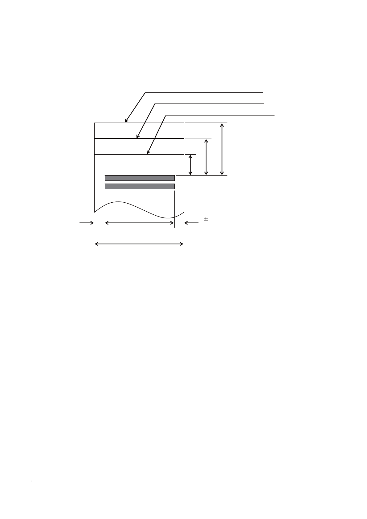
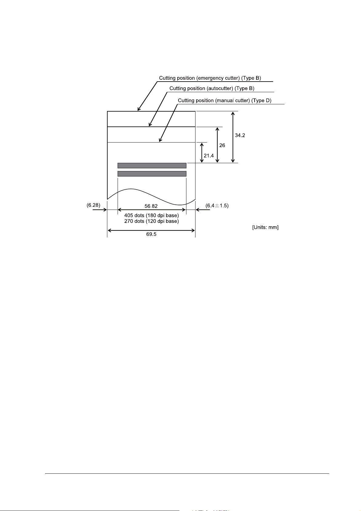
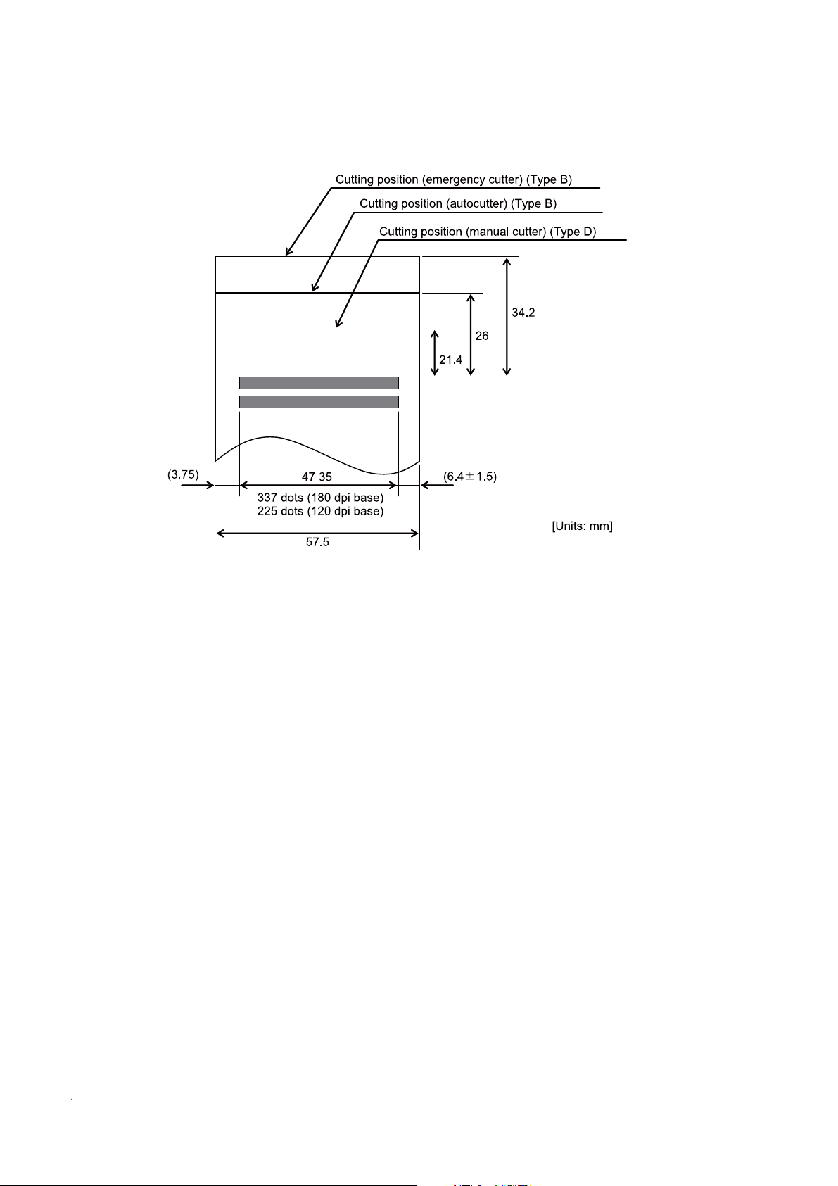
1.5.2.2 Printable Area
Cutting position ( emergency cutter) (Type B)
Cutting position (autocutter) (Type B)
Cutting position (manual cutter) (Type D)
34. 2
26
21.4
(6. 46)
63.14
450 dots (180 dpi base)
300 dots (120 dpi base)
76
Printable area for 76 mm width paper
(6.4
1.5)
[Units: mm]
1-8 General Information
Page 17
TM-U330 Technical Reference Guide
Printable area for 69.5 mm width paper
General Information 1-9
Page 18
Printable area for 57.5 mm width paper
1-10 General Information
Page 19
1.6 Other Specifications
1.6.1 Reliability
Life: Mechanism: 10,000,000 lines
Print head: 200 million characters (using an average of 1 dot/wire per character).
(The printing pattern is Epson test pattern).
Autocutter: 1,000,000 cuts
End of life is defined as the point at which the printer reaches the beginning of the
wear-out period.
MTBF: 180,000 hours
Failure is defined as a Random Failure occurring at the time of the Random Failure
Period.
MCBF: 24,000,000 lines
This is an average failure interval based on failures relating to Wearout and Random
Failures up to the life of 10 million lines.
TM-U330 Technical Reference Guide
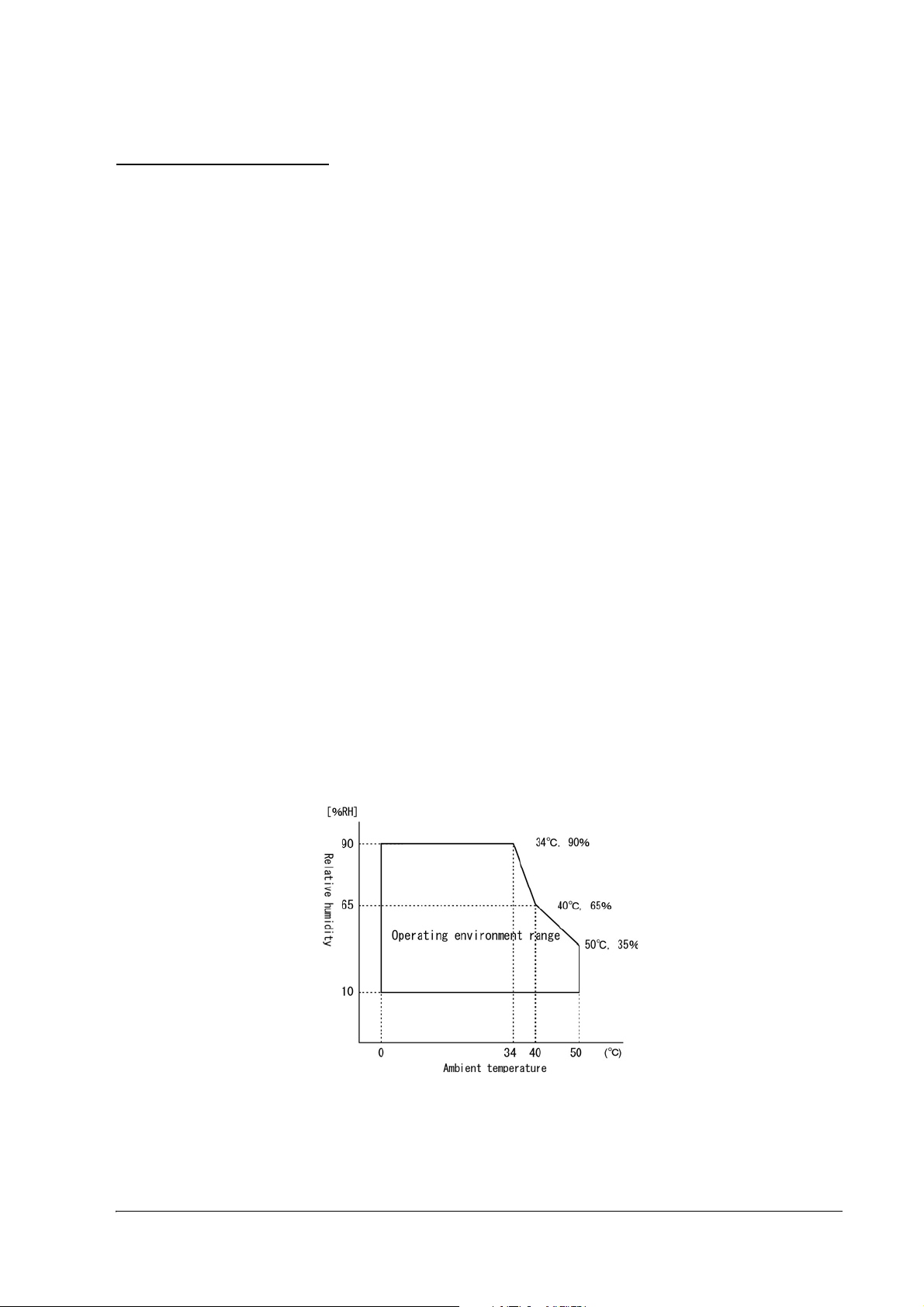
1.6.2 Environmental Conditions
Temperature: During operation: 0 to 50 C {41 to 122 F}.
(At 34 C {93F} or higher, there are humidity restrictions as listed below. )
Humidity: During operation:10 to 90% (no condensation)
During storage:10 to 90% (no condensation; excludes paper and ribbon)
Operating temperature and humidity range
General Information 1-11
Page 20

Vibration resistance: When packed:
Frequency: 5 to 55 Hz
Acceleration: 19.6m/s
Sweep: 10 minutes (half cycle)
Duration: 1 hour
Directions: x, y, and z
No external or internal damage should be found after the vibration test, and
the unit should operate normally.
Impact resistance: When packed:
Package: EPSON standard package
Height: 60 cm (2 feet)
Directions: 1 corner, 3 edges, and 6 surfaces
No external or internal damage should be found after the drop test, and the
unit should operate normally.
When unpacked:
Height: 5 cm (2")
Directions: Lift one edge and release it (for all 4 edges).
When the printer is not printing, no external or internal damage should be
found after the drop test.
2
{2 G}
1.6.3 Installation
Install the printer horizontally as a basic position.The printer also must be installed so that it does not
move or vibrate during paper cutting or the drawer kick operation. Affixing tape is available as an option.
1-12 General Information
Page 21

1.7 External Dimensions and Mass
[Unit: mm]
1.7.1 External Dimensions and Mass
Model type External Dimensions Mass
Width Height Depth
Type B 160 mm
{Approximately 6.3"}
Type D 160 mm
{Approximately 6.3"}
(All the numeric values are typical.)
Color: EPSON standard color (ECW, EDG)
1.7.1.1 Overview (Type B)
144 mm
{Approximately 5.7"}
144 mm
{Approximately 5.7"}
248 mm
{Approximately 9.8"}
248 mm
{Approximately 9.8"}
TM-U330 Technical Reference Guide
Approximately 2.8 kg
Approximately 2.6 kg
General Information 1-13
Page 22

1.7.1.2 Overview (Type D)
[Unit: mm]
1-14 General Information
Page 23

TM-U330 Technical Reference Guide
Chapter 2
System Planning
This section provides you information for system planning.
2.1 Control Method
Use a driver, ESC/POS commands, or Epson ePOS SDK to control the printer.
2.1.1 Selecting a Driver
Choose one of the drivers listed in "Printer Drivers" (page 2-2), depending on the application operating
environment.
For information about the driver operating environment, see the installation manual for each driver.
2.1.2 ESC/POS Commands
ESC/POS is the Epson original printer command system. With ESC/POS commands, you can directly
control all the TM printer functions, but detailed knowledge of printer specifications or combination of
commands is required.
For information about ESC/POS commands, see the product specification. You need a non-disclosure
agreement with Epson to get the product specification. Contact the dealer for more details.
2.1.3 Epson ePOS SDK
The Epson ePOS SDK is an SDK for developing iOS, Android and Windows applications, and Web
applications. You can use the Epson ePOS SDK to control the printer with simple code.
Additionally, you can control customer displays, bar code scanners and other POS peripherals connected
to this product, and TM printers connected to the network.
The following packages are provided.
❏ Epson ePOS SDK for iOS
❏ Epson ePOS SDK for Android
❏ Epson ePOS SDK for Universal Windows apps
❏ Epson ePOS SDK for JavaScript
Note:
For detailed information about Epson ePOS SDK, see the User's Manual of Epson ePOS SDK.
System Planning 2-1
Page 24

2.2 Software and Manuals
The following software and manuals are provided for application development.
2.2.1 How to Get Software and Manuals
You can obtain software and manuals from the following URL.
http://download.epson-biz.com/?service=pos
2.2.2 Printer Drivers
Software Manual
EPSON Advanced Printer Driver (APD):
In addition to ordinary Windows driver functions, this driver has
controls specific to POS, such as controls for paper cut, a cash drawer,
or customer display. The Status API (Epson original DLL) that monitors
printer status and sends ESC/POS commands is also attached to this
driver.
OPOS ADK:
This OCX driver can control POS peripherals using OLE technology
Because controlling POS peripherals with original commands is not
required on the application side, efficient system development is
possible.
EPSON TM Virtual Port Driver:
This driver is a Serial-USB and Parallel-USB conversion driver to make an
EPSON TM/BA/EU printer connected via USB accessible from a POS
application through virtual COM ports and a virtual LPT port. Without
making changes in the POS application that controls devices
connected through serial or parallel interfaces, devices connected via
USB can be directly controlled with ESC/POS commands.
❏ APD Install Manual
❏ APD Printer Manual
❏ APD Printer Specification
❏ Status API Manual
❏ Sample Program Guide
❏ OPOS Installation Manual
*1
.
❏ User’s Manual
❏ Application Development Guide
❏ UnifiedPOS Retail Peripheral Architecture
❏ Sample Program Guide
TM Virtual Port Driver User’s Manual
*2
*1 OLE technology developed by Microsoft divides software into part blocks. The OPOS driver is presupposed to be used with a
development environment, such as Visual Basic, unlike ordinary Windows drivers. It is not a driver to be used for printing from
commercial applications.
*2 This guide describes general information on how to control printers using the OPOS ADK (in the chapter “POS Printer” and
“Appendix”). It does not describe Epson’s specific functions.
2-2 System Planning
Page 25

TM-U330 Technical Reference Guide
2.2.3 Utilities
CAUTION:
After using the following utilities via the USB interface, be sure to disconnect the USB cable, turn off the
printer, and then turn it back on.
❏
EpsonNet Config
❏
Deployment Tool
❏
Printer Network Setting (included in APD)
Software Manual
TM-U330 Utility:
Use for checking and setting the following functions:
❏ Current settings
❏ Storing logos
❏ Paper reduction
❏ Printing control
❏ Interface
❏ Backup/restore
❏ Operation check
❏ Cut Positioning
EpsonNet Config:
Use for wireless LAN setting. For Windows and Mac.
Monitoring Tool:
Use to check a list of status for the Epson printers connected to the
network.
Use with Monitoring Tool and TM-U330 Utility to check the status and
make settings from the administrator's computer for the printer that is
directly connected to the network, or the printer that is connected to
the client computer over a network by USB.
Deployment Tool:
Use to configure network settings and printer/driver settings in a
batch. It enables deploying more than one printer/driver efficiently and
quickly for initial installation.
TM-U330 Utility User’s Manual
EpsonNet Config manual (operation guide) or EpsonNet
Config online help
Monitoring Tool User’s Manual
Deployment Tool User’s Manual
2.3 Connecting the Optional Customer Display
You can connect the customer display to this product.
For more information, refer to "DM-D110/DM-D210 Technical Reference Guide".
System Planning 2-3
Page 26

Chapter 3
roll paper cover
ribbon cassette cover
power switch
control panel
manual cutter
Setup
3.1 Part Name and Basic Operation
3.1.1 Part name
3.1.1.1 Connectors
Do not connect a telephone line to the drawer kick connector or the display module connector; otherwise
the printer and the telephone line may be damaged.
You can connect up to four cables to the printer. They all connect to the connector panel (on the bottom
rear of the printer), which is shown below.
Note:
This illustration shows the serial interface model. The other interface connector looks slightly different.
WARNING:
3-1 Setup
Page 27

3.1.2 The Control Panel
The layout varies according to the model.
❏ POWER LED
❏ ERROR LED
❏ PAPER OUT LED
❏ FEED button
3.1.2.1 LED
POWER
On: Power supply is stable.
Off: Power supply is not stable.
TM-U330 Technical Reference Guide
ERROR
When this light is on but not blinking, it means that the printer is offline. Check to see if a cover is open.
When this light is blinking, there is an error. See “LED Blinking Pattern” in Chapter 4.
PAPER OUT
On: The roll paper near end (*1) or real end is detected.
Off: Paper is loaded (normal condition).
Flashing: Self-test waiting state for test print.
Note:
The roll paper near-end sensor is available as an factory option. If the printer is not equipped with the roll paper
near-end sensor, the roll paper near-end is always detected as paper present. See "Adjusting Position of Roll Paper
Near End Detector (factory option)" (page 3-22) for information on adjusting the detector.
3.1.2.2 Control Panel Buttons
The control panel has paper button that you may have to use, although most paper handling functions will
be handled by your software.
FEED
Use this button to feed roll paper or to start a roll paper self test. (See "Self Test Procedure" (page 3-23).)
Note:
The FEED button can be disabled by using an ESC/POS command.
Setup 3-2
Page 28

3.2 Setup Flow
5. Complete set up
2. Adjust various settings (If you need to)
❏ Memory switches
❏ Paper width
(Adjust the spacer & Memory switches)
❏ Roll Paper Near End Detector
(For equipped model only)
(See "Adjusting Various Settings" (page 3-14))
4. Driver setup
❏OPOS
❏ APD
(See "Install a Printer Driver in the Host PC / POS
Terminal," page 3-23)
When you select Direct
control method (ESC/
POS command,) you
don’t need to install any
drivers.
1. Printer set up
❏Install Ribbon Cassette
❏Install Paper Roll
❏ Connect the Printer to the Power Supply
(See "Printer setup," page 3-5)
3. Connect the Printer to the host PC/POS terminal
(See "Install a Printer Driver in the Host PC / POS Terminal" (page 3-23))
You have to set up your printer to use it. And you can adjust some features by customizing them. This
section describes the setup.
The set up flow of preparing to use printer is below.
3-3 Setup
Note:
When you use OPOS (OCX driver from EPSON) or the Advanced Printer Driver, you need to install the driver.
When you use ESC/POS commands, you don’t have to install drivers. For information on these drivers, see
“Control Method” on page 2-1 and "Install a Printer Driver in the Host PC / POS Terminal" (page 3-23).
Page 29

TM-U330 Technical Reference Guide
The following sections describe the setup. The flow of preparing to use printer is listed below.
1. Printer setup
•Install Ribbon Cassette ("Installing or Replacing the Ribbon Cassette" (page 3-5))
•Install Paper Roll ("Installing the Roll Paper" (page 3-7))
•Connect the Printer to the Power Supply ("Connecting the AC Adapter" (page 3-9))
2. Adjust various setting ( If you need to)
When you use this printer with a serial interface, you have to adjust the communication settings.
See "Memory Switches" (page 3-14) for how to set them.
•Memory switches ("Memory Switches" (page 3-14))
The Memory switches set serial communication conditions, roll paper width, cover
open status handling, etc...
•Paper width ("Adjusting Roll paper width" (page 3-21))
The paper width is set by the spacer & Memory switch setting.
•Roll Paper Near End Detector (For model equipped with the detector)
("Adjusting Position of Roll Paper Near End Detector (factory option)" (page 3-22))
3. Connect the Printer to the Host PC/POS Terminal (and Cash Drawer)
("Install a Printer Driver in the Host PC / POS Terminal" (page 3-23))
4. Driver set up (If you use driver)
("Install a Printer Driver in the Host PC / POS Terminal" (page 3-23))
5. Complete the setup
Setup 3-4
Page 30

3.3 Printer setup
3.3.1 Installing or Replacing the Ribbon Cassette
CAUTION:
The print head becomes very hot during printing. Allow it to cool before you replace the ribbon cassette.
1. Open the ribbon cassette cover.
2. Turn the knob 2 or 3 times in the direction of the arrow.
!CAUTION:
Use the EPSON ERC-45 ribbon cassette for your printer.
Never turn the ribbon cassette’s feed knob in the opposite direction of the arrow marked on the cassette;
otherwise the ribbon cassette may be damaged.
3-5 Setup
Page 31

TM-U330 Technical Reference Guide
3. Insert the ribbon in the position and push the ribbon cassette down until it clicks.
Make sure the ribbon is installed between the print head and the platen without wrinkles or creases.
4. Again turn the ribbon cassette’s knob 2 or 3 times in the direction of the arrow.
CAUTION:
Be careful not to touch the print head with your fingers when turning the ribbon cassette knob because the
print head is hot and you might be burned.
5. Close the ribbon cassette cover.
Setup 3-6
Page 32

3.3.2 Installing the Roll Paper
✄
ON
!CAUTION:
❏
Be sure to use roll paper that meets the specifications.
❏
Be sure not to touch the manual cutter. Otherwise your fingers might be injured.
1. Using scissors, cut the leading edge of the roll paper.
2. Turn on the printer.
3. Open the roll paper cover.
3-7 Setup
Page 33

TM-U330 Technical Reference Guide
4. Insert the roll paper.
Note the direction the paper comes off the roll.
QNote:
When using 2-ply roll paper, be sure that the top and bottom sheets are aligned at the paper exit.
5. Close the roll paper cover.
Setup 3-8
Page 34

3.3.3 Connecting the AC Adapter
AC adapter
AC cable
!WARNING:
❏
Never insert the AC cable plug into a socket that does not meet the rated voltage requirements of the
printer.
Doing so may result in damage to the printer.
❏
Should a fault ever occur, immediately turn off the power to the printer and unplug the AC cable from
the wall socket.
3.3.3.1 Connecting the AC cable
1. Make sure the printer is turned off.
2. Connect the AC cable to the AC adapter.
3. Connect the DC cable of the AC adapter to the power supply connector.
4. Insert the AC plug into a wall socket.
3-9 Setup
Page 35

TM-U330 Technical Reference Guide
3.3.4 Connecting the Printer to the Host PC / POS Terminal
All cables are connected to the connector panel located on the lower rear side of the printer.
Connector panel
Note:
The figure above shows the connector panel for the serial interface model printer. The shape of the interface
connector varies according to the type of interface used.
Be sure to turn off the power supply for both the printer and the host computer unit before connecting the various
cables.
You need an appropriate serial, parallel, USB, or Ethernet interface cable to connect your computer to the printer.
For the serial model, it is important that you use a null modem cable, not any other serial cable, and for the
parallel model use an IEEE 1284 cable.
3.3.4.1 Serial Interface
Before connecting any of the cables, make sure that both the printer and the host PC are turned off.
1. Plug the cable connector securely into the printer’s interface connector.
2. If the cable connector has screws on it, tighten the screws on both sides of the connector.
3. If your interface connector has a grounding wire, attach it to the printer using the screw labeled FG,
which is next to the interface connector.
4. Attach the other end of the cable to the host PC.
Setup 3-10
Page 36

3.3.4.2 Parallel Interface
1. Press the connector on the end of the interface cable firmly into the interface connector on the
connector panel.
2. Press down the clips on either side of the connector to lock it in place.
3. For interface cables equipped with a ground line, attach the ground line to the screw hole marked "FG"
on the printer.
4. Connect the other end of the interface cable to the host computer.
3.3.4.3 USB Interface
1. Attach the locking wire saddle at the location shown in the figure below.
2. Hook the USB cable through the locking wire saddle, as shown in the figure below.
Note:
Hooking the USB cable through the locking wire saddle, as shown in the figure below, will prevent the
cable from coming unplugged.
Attaching locking wire saddle
3. Connect the USB cable from the host computer to the USB upstream connector.
3-11 Setup
Page 37

TM-U330 Technical Reference Guide
3.3.4.4 Ethernet interface
!CAUTION:
❏
When Ethernet cables are installed outdoors, make sure devices without proper surge protection are
cushioned by being connected through devices that do have surge protection.
Otherwise, the devices can be damaged by lightning.
❏
Never attempt to connect the customer display cable, drawer kick cable, or the standard telephone line
cable to the Ethernet connector.
Note:
The display module connector on the TM printer cannot be used when the UB-E** is installed.
Connect an Ethernet cable to the Ethernet connector by pressing firmly until the connector clicks into
place.
Setup 3-12
Page 38

3.3.4.5 Connecting a Drawer
DK
CAUTION:
Be sure to connect a drawer that meets printer specifications. Connecting a drawer of the wrong
specifications may result in damage to both the drawer and the printer.
Never connect the telephone line to the drawer kick connector (labeled “DK”). Doing so may result in
damage to both the telephone line and the printer.
Never connect the drawer cable to the customer display connector (labeled “DM-D”). Doing so may result in
damage to both the drawer cable and the printer.
1. Connect the drawer cable to the drawer kick connector (labeled “DK”) on the connector panel.
2. The connecting is finished.
Connecting drawer
3-13 Setup
Page 39

TM-U330 Technical Reference Guide
3.4 Adjusting Various Settings
This printer is able to be adjusted for the items below:
❏ Memory switch (serial communication conditions, roll paper width, cover open status handling, etc...)
❏ Roll paper width (76mm / 69.5mm / 59.5mm)
Adjusting the spacer & memory switch
❏ Position of roll paper near end detector (factory option)
The current settings can be confirmed by a self test. (See "Self Test" (page 3-23).)
3.4.1 How to Confirm Current Settings
You can use a self-test to confirm the current settings. See "Self Test" on page 3-23.
3.4.2 Memory Switches
This printer has “Memory switch“ set which is software switches. The memory switch set consists of the
following:
❏ Msw1, Msw2, Msw5, Msw8
❏ Customize value
❏ Serial communication condition
❏ USB communication condition
Note:
Settings of the memory switch are stored in the NV memory; therefore, even if the printer is turned off, the settings
are maintained. Excessive use of this function may destroy the NV memory. As a guideline, do not use this
function more than 10 times a day.
When you use OPOS or APD, generally you don’t need to adjust memory switch because OPOS or APD are able to
set these items automatically.
The memory switch can also be set by using the TM-U330 Utility.
Setup 3-14
Page 40

Msw1
SW Function Off On Default
1-1 (reserved) - - Off
1-2 Receive buffer capacity 4 KB 40 bytes Off
1-3 Condition for BUSY Receive buffer full or
Offline
1-4 Data processing for receive error Replaced with "?" Ignored Off
1-5 Automatic line feed Disabled Enabled Off
1-6 (reserved) - - Off
1-7 #6 pin of RS-232 Not used Used for reset signal Off
1-8 #25 pin of RS-232 Not used Used for reset signal Off
Receive buffer full Off
Note:
[Msw1-4], [Msw1-7], [Msw1-8]: Valid only for serial interface
[Msw1-5]: Valid only for parallel interface
[Msw1-8]: Fixed to On with LAN interface model
Msw2
SW Function Off On Default
2-1 (reserved) - - On
2-2 Autocutter function Disabled Enabled On (TM-U330B)
2-3 Character code system for the simplified
Chinese (for Simplified Chinese
characters model)
2-4 (reserved) - - Off
2-5 (reserved) - - Off
2-6 (reserved) - - Off
2-7 (reserved) - - Off
2-8 (reserved) - - Off
GB18030 GB2312 Off
Off (TM-U330D)
3-15 Setup
Page 41

TM-U330 Technical Reference Guide
Msw5
SW Function Off On Default
5-1 USB power-saving Enabled Disabled Off
5-2 (reserved) - - Off
5-3 Paper sensor to output paper end
signals
5-4 (reserved) - - Off
5-5 (reserved) - - Off
5-6 (reserved) - - Off
5-7 (reserved) - - Off
5-8 (reserved) - - Off
Enabled both paper end
sensor and near-end
sensor
Disabled Off
Note:
[Msw5-1]: Valid only when the USB interface communication condition is set to the Vendor-defined class and the
system configuration is set so that the USB driver can support the USB power-saving function.
Msw8
SW Function Off On Default
8-1 Black mark sensor Disabled Enabled Off
8-2 (reserved) - - Off
8-3 Status when paper end Offline Online Off
8-4 (reserved) - - Off
8-5 Selection of the cover open status Paper end Cover open Off
8-6 Error signal output when an error occurs Enabled Disabled Off
8-7 Recovery conditions from receive buffer
BUSY
8-8 Printer cover open during operation Automatic recoverable
Remaining 138 bytes Remaining 256 bytes Off
Recoverable error Off
error
Note:
Msw 8-5:
When Off is selected, a bit of the "roll paper end sensor" in each status that is transmitted from the printer is
changed every time the roll paper cover is open or closed. When On is selected, a bit of the "roll paper cover open /
close" in each status that is transmitted from the printer is changed every time the roll paper cover is open or closed.
Msw 8-8:
When Off is selected, a bit of the "automatic recoverable error" in each status that is transmitted from the printer is
changed every time the roll paper cover is open. When On is selected, a bit of the "mechanical error" in each status
that is transmitted from the printer is changed every time the roll paper cover is open.
Setup 3-16
Page 42
Customize value
Function Selectable value Default
Roll paper width 57.5 mm, 69.5 mm, 76 mm 76 mm
Roll paper text control mode Mode 1, Mode 2, Mode 3 Mode 1
Select interface type Fixed UIB, fixed Built-inUSB, auto change between UIB/Built-
inUSB
Execute commands while offline Enable/Disable Disable
Set amount of cut justification for
paper
–37 to 598 mm 0 mm
Auto change between UIB/
Built-inUSB
Auto paper saving function
Reduce top margin
Auto paper saving function
Reduce bottom margin
Auto paper saving function
Amount of reduction
Auto paper saving function
Amount of reduction for carriage
returns
Do not reduce margin space Reduce margin space Do not reduce margin space
Do not reduce margin space Reduce margin space Do not reduce margin space
Do not reduce Reduce by 25% Do not reduce
Reduce by 50% Reduce by 75%
Do not reduce Reduce by 25% Do not reduce
Reduce by 50% Reduce by 75%
Note:
When the mark sensor is enabled, you cannot set a paper width of 69.5 mm.
When the mark sensor is enabled, the Auto paper saving function is disabled.
Serial communication condition
Function Selectable value Default value
Baud rate 1200 bps 2400 bps 115200 bps
4800 bps 9600 bps
19200 bps 38400 bps
57600 bps 115200 bps
Parity None Odd None
Even -
Handshake DSR/DTR XON/XOFF DSR/DTR
Data length 7 bit 8 bit 8 bit
3-17 Setup
Page 43

TM-U330 Technical Reference Guide
USB interface communication condition
Function Selectable value Default value
Class Vendor-defined class Printer class Vendor-defined class
IEEE1284 Device ID Do not send IEEE1284 Device IDSend IEEE1284 Device ID Send
3.4.3 Memory Switch Setting Mode
The following items are specified in the memory switch setting mode:
❏ Serial Interface Settings
❏ Interface Selection
❏ USB Interface Settings
❏ Command Execution (Offline)
❏ Autocutter
❏ Black Mark Sensor
❏ Interface Signal Settings
3.4.3.1 Starting the memory switch setting mode
Use the following procedure to start the memory switch setting mode.
1. Open the roll paper cover.
2. Turn the power on while pressing the paper FEED button.
3. Press the FEED button twice while ERROR LED is lit.
4. Close the cover. The printer prints the enabled settings of the memory switches and instructions.
5. Follow the instructions to process the switch setting.
Note:
In Memory switch setting mode, the flashing paper out LED indicates user operations are necessary.
3.4.3.2 Ending memory switch setting mode
To finish Memory switch setting mode, turn off the printer, or select "Exit" to return to the first selection
guide.
Setup 3-18
Page 44

3.4.3.3 Operating procedure
Entering Memory Switch Setting Mode
Selecting Items to Set
Selecting the set value
Ending Memory Switch Setting Mode
0: Exit
1: Print Current Settings
2: Serial Interface Settings
3: Interface Selection
4: USB Interface Settings
5: Command Execution (Offline)
After briefly pressing the FEED button (less than one second) for the number of times shown in the
print result, hold down the button for more than one second, and then select the setting items.
The setting selected as the setting item, the current settings and initial settings are printed.
Depending on the setting item, you may need to continue making the setting item before the
settings are printed.
Select a setting by briefly pressing the FEED button (less than one second) for the number of times
applicable to the setting, and then hold down the button for more than one second to confirm your
selection.
After saving the settings, the Memory switch setting mode is printed, and the Paper LED flashes.
1.Open the roll paper cover and turn the power on while pressing the paper FEED button.
2.Press the paper FEED button twice while ERROR LED is lit.
3.Close the cover.
The printer prints the setting guideline.
Turn off the printer, or select "Exit" to return to the first selection guide.
The procedures used for this process are described below.
3-19 Setup
Page 45

3.4.3.4 Setting items for Memory switch setting mode
Setting Items Options
1: Print Current Settings -
2: Serial Interface
Settings
3: Interface Selection UIB, Built-in USB, Auto
4: USB Interface
Settings
5: Command Execution (Offline) Enable, Disable
6: Other settings 1: Autocutter TM-U330B: Enable, Disable
1: Baud Rate 1200 bps, 2400 bps, 4800 bps, 9600 bps, 19200 bps, 38400
2: Parity None, Odd, Even
3: Handshaking DTR/DSR
4: Data Bits 7 bits, 8 bits
1: Class Vendor Class, Printer Class
2: Black Mark Sensor Enable, Disable
3: Interface Settings 1: Output Paper-end
Signals
2: Error Signal Enable
3: Pin 6 Reset Signal Enable, Disable
4: Pin 25 Reset Signal Enable, Disable
bps, 57600, bps, 115200 bps
TM-U330D: Enable, Disable
Enable, Disable
, Disable
TM-U330 Technical Reference Guide
* The initial setting is underlined.1st page 2nd page 3rd page
, XON/XOFF
Setup 3-20
Page 46

3.4.4 Adjusting Roll paper width
leading the wires
between the holder
and frame
Roll paper guide
Roll paper holder
B
C
A
Roll paper
guide
position of fixing
the screws
(left side)
position of fixing
the screws
(right side)
A: paper width76 mm
B: paper width69.5mm
C: paper width57.5mm
The TM-U330 accommodates 76 mm {3"},69.5 mm {2.74"}, 57.5 mm {2.26"} wide paper rolls.
Note:
When you use a near-end detector equipped model, be sure not to pinch the lead wires of the near-end detector
between the roll paper guide and the roll paper holder, and to push the lead wires inside so that the lead wire of the
paper-end detector does not contact the motor gear.
When replacing the wires, be sure that the wires do not catch between the roll paper guide and the roll paper
holder.
3-21 Setup
1. Make sure the power supply is disconnected.
2. Open the roll paper cover.
3. Take off the roll paper guide from the printer by loosening the two screws.
4. Push the roll paper guide on the appropriate width (See figure above.)
Page 47

TM-U330 Technical Reference Guide
Detector
adjustment screw
Knob
#2 setting
#1 setting
Detector lever
Seeing at outside for roll paper spacer
5. Tighten the spacer with two screws included with the guide. (See figure above.)
6. Set the memory switch (customize value) for the paper width. (See "Memory Switches" (page 3-14))
3.4.5 Adjusting Position of Roll Paper Near End Detector (factory option)
Below are two reasons for the roll paper to require an NE detector adjustment.
❏ To adjust the location of detection for the diameter of the roll paper core.
❏ To adjust the amount of remaining paper.
The procedure is as following.
1. Make sure the power supply is disconnected.
2. Open the roll paper cover, and remove the paper roll.
3. Loosen the detector adjustment screw with a coin or similar tool.
4. Adjust the detector by sliding the lever in the direction shown below.
The table below shows the point at which the near-end detector is triggered. Note that this figure is a
calculated value, and there may be some variations, depending on the printer.
Detection point of roll paper near-end
Detector position (attaching point of the
detector adjustment lever) Trigger point (included the thickness of paper roll core)
#1 setting Approx. 8 mm
#2 setting Approx. 5 mm
5. Tighten the detector adjustment screw.
6. Check to be sure that the detecting lever moves freely.
Setup 3-22
Page 48

3.5 Install a Printer Driver in the Host PC / POS Terminal
EPSON provides printer drivers for the TM-U330. The drivers are OPOS and Advanced Printer Driver
(APD). They are for the Windows environment.
3.5.1 OPOS
When you install and set up, please refer to the User's Manual, the file is automatically created at the
installation of OPOS ADK.
3.5.2 Advanced Printer Driver (APD)
When you install and set up the APD, please refer to the “EPSON Advanced Printer Driver Install
Manual.“
3.6 Self Test
The self test lets you know if your printer is operating properly. It checks the control circuits, printer
mechanisms, print quality, control software version, and the memory switch settings.
This test is independent of any other equipment or software, so it is a good idea to run it when you first set
up the printer and if you have any trouble. If the self tests work correctly, the problem is in the other
equipment or the software, not the printer.
3.6.1 Self Test Procedure
1. Make sure the printer is turned off and the roll paper cover is closed properly.
2. While holding down the FEED button, turn on the printer using the switch on the front of the printer.
The self test prints the printer settings and then prints the following, cuts the paper, and pauses. (The
PAPER OUT light blinks.)
If you want to continue
SELF-TEST printing,
please press FEED button.
3. Press the FEED button to continue printing. The printer prints a pattern using the built-in character
set.
4. The self test automatically ends and cuts the paper after printing the following:
*** completed ***
The printer is ready to receive data as soon as it completes the self test.
Note:
If you want to pause the self test manually, press the FEED button. Press the FEED button again to continue the self
test.
3-23 Setup
Page 49

TM-U330 Technical Reference Guide
Chapter 4
Troubleshooting
This section describes general troubleshooting.
4.1 LED Blinking Pattern
4.1.1 Error Types
The printer stops all printer operations for the selected paper section, goes offline, and the ERROR LED
blinks when an error is detected.
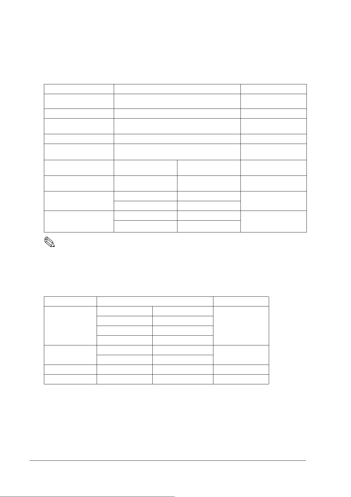
4.1.1.1 Errors that automatically recover
ERROR Description ERROR LED Blinking Pattern Recovery
Roll paper cover open
error (when recoverable
error is selected)
(*1)
The roll paper cover is opened
when printing.
Recovers automatically
when the cover is closed.
Print head temperature
(*2)
error
Black Mark (BM) Error The mark is undetectable if
The temperature of the print
head is extremely high.
paper is fed for 598 mm or
more.
Recovers automatically
when the print head cools.
B, D type:
Open/close the roll paper
cover.
Note:
(*1) This conditions are selected by MSW 8-5, 8-8. When MSW 8-5 (mapping of the cover open status) is off,
the error hasn’t occurred but there is a “paper end error” instead. If MSW 8-8 is off, this error is handled as
an automatically recoverable error.
(* 2) Print head temperature error is not abnormal.
Troubleshooting 4-1
Page 50

4.1.1.2 Recoverable Errors
When a recoverable error occurs, after the cause of the error is removed, the printer can recover from the
error by receiving an error recovery command without turning off the power:
ERROR Description ERROR LED Blinking Pattern Recovery
Roll paper cover open
error (*1)
The roll paper cover is
opened when printing.
Recovers by error recovery
command with the cover closed
Autocutter error
(TM-U330B only)
Home position detection
error
(This is “Mechanical
error“)
The autocutter does not
work correctly
The home position cannot
be detected due to a paper
jam
Recovers by error recovery
command. (See "Autocutter Jam"
(page 4-4))
Recovers by error recovery
command
Note:
(*1) These conditions are selected by MSW 8-5 and 8-8. When MSW 8-5 (mapping of the cover open status)
is OFF, the error does not occur and a “paper end error” occurs instead. If MSW 8-8 is ON, this error is
handled as a recoverable error.
4.1.1.3 Errors that are impossible to recover:
ERROR Description ERROR LED Blinking Pattern Recovery
R/W error in memory or
gate array
High voltage error The power supply voltage is
After R/W checking, the printer
does not work correctly.
Writing to, reading out, or
erasing the NV memory for
image scanning results does not
work correctly.
extremely high.
Impossible to recover
Impossible to recover
Low voltage error The power supply voltage is
extremely low.
4-2 Troubleshooting
Impossible to recover
Page 51
TM-U330 Technical Reference Guide
Roll paper cover
Tab
ERROR Description ERROR LED Blinking Pattern Recovery
CPU execution error The CPU executes an incorrect
address or I/F board is not
connected.
Impossible to recover
Circuit error There is an error in the head
temperature or the motor driver
IC temperature.
UIB error There is an error in the I/F board. Impossible to recover
Impossible to recover
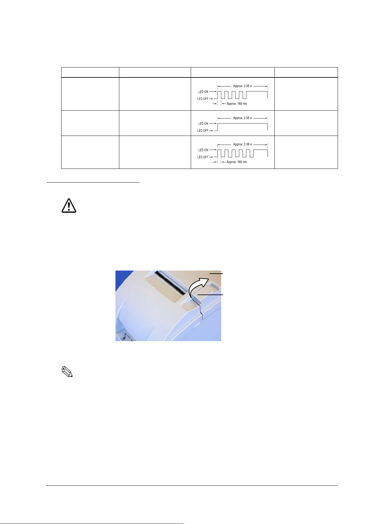
4.2 Removing a Paper Jam
CAUTION:
Be sure not to touch the manual cutter. Otherwise your finger might be injured.
1. Turn the power off.
2. Open the roll paper cover by using the tab, as shown in the below illustration.
3. Remove the jammed paper.
Note:
When you turn the power off by mistake during the printing operation, the cutter blade may stop in the paper
feed line. So the paper may not be fed in the first operation normally when you turn the power on. If the
phenomenon happens again after removing the jammed paper, try the solution "Autocutter Jam" (page 4-4).
Troubleshooting 4-3
Page 52

4.3 Autocutter Jam
Cutter cover
Autocutter unit
Lever
Hole
Knob
If a foreign object such as a push pin or paper clip drops in the autocutter and causes the auto cutter to lock
up, the printer enters an error state and begins the recovery operation automatically.
If the problem is not serious, the autocutter returns to its normal position without any intervention by the
user.
If the autocutter does not return to its normal position by itself, follow the steps below to fix the problem:
1. Open the roll paper cover, and remove the jammed object if there is one.
2. Turn off the printer, and close the roll paper cover, and turn it back on. Then the cutter blade returns
to the normal position. If you would like not to turn off the printer, send an error recovery command
and initialize printer command instead.
3. If the cutter blade doesn’t return to the normal position, return the cutter blade to the normal position
by rotating the autocutter knob in the direction of the arrow. When it is returned to the normal
position, a lever comes into the center of hole in the autocutter frame.
4-4 Troubleshooting
4. Close the roll paper cover.
Page 53

TM-U330 Technical Reference Guide
4.4 Printer prints “?“ or Incorrect Data With Serial Interface
If one of the following errors occurs during serial interface communication, the printer prints “?” or
ignores the data, depending on the setting of the memory switch Msw1-4.
❏ Parity error
❏ Framing error
❏ Overrun error
4.5 Print Speed is Slow When Using Windows Printer Driver
When the printer prints a Windows font using the EPSON Advanced Printer Driver, the print speed is
slow. To improve the print speed, use a printer font.
4.6 Printer doesn’t cut roll paper with the autocutter
TM-U330D does not have an autocutter unit. If you use the model, you can’t use the autocutter function.
Use the manual cutter.
Troubleshooting 4-5
Page 54

Chapter 5
Application Development Information
This section contains usable information to develop POS systems that use this printer.
5.1 Various Status Categories
This printer is able to send various status reports to the host PC. This section describes about the kind of
statuses and handling.
Status Categories Description
Drawer kick connector pin status Cash drawer is open or closed.
Roll Paper cover status Roll paper cover is open or closed
Paper feeding button status Paper feed button is pressed or not
Error status Various error information (Off-line / On-line), (detail of the error; Mechanical error,
autocutter error, auto-recovery error, unrecoverable error)
Paper remaining amount status It provides status of paper remaining amount (Near-end or Paper end)
Note
Near-end status (paper remain status) is supported only by printers equipped with a near-end detector.
The near-end detector is a factory option.
This printer has an Automatic status back (ASB) function that automatically transmits changes in
printer status. It is available in any control method (APD, OPOS, ESC/POS command.)
The status format depends on each control method. Refer to each manual for detail.
The statuses are useful for the following situations.
❏ When an error status is sent to the host PC, the host PC can display an error message or solution
message for operator.
❏ When “Paper near end” or “Paper end“ status is sent to the host PC, the host PC can display a warning
message for operator to replace roll paper.
5.1.1 Printer Status on APD
When you use APD to get printer’s status, you have to install “Status API“ and use it. Refer to “Status API
User’s Manual“ and the sample program of Status API for details.
5-1 Application Development Information
Page 55

TM-U330 Technical Reference Guide
If OPOSPOSPrinter1.CoverOpen = True Then
MsgBox “Cover is open!”
End If
[Event management]
Private Sub OPOSPOSPrinter1_StatusUpdateEvent(ByVal Data As Long)
If Data = PTR_SUE_COVER_OPEN Then
MsgBox “Cover is open!”
End If
End Sub
5.1.2 OPOS
Note
This section describes the summary of status handling. Refer to “OPOS ADK Application Development
Guide General Functions” for details.
5.1.2.1 Checking the printer state
The state of the printer can be checked through properties supported by the printer. For example, if the
user wants to check if the printer cover is open, the CoverOpen property can be used.
This and many other events can also be checked by firing a StatusUpdateEvent.
StatusUpdateEvent can return information on the following items.
STATUS INFORMATION
PTR_SUE_COVER_OPEN Cover is open.
PTR_SUE_COVER_OK Cover is closed.
PTR_SUE_REC_EMPTY Receipt paper is out.
PTR_SUE_REC_NEAREMPTY Receipt paper is near the end. (The near end detector is factory option.
PTR_SUE_REC_PAPEROK Receipt paper is OK.
PTR_SUE_IDLE Printer State is idle.
When the printer does not have one, the status does not occur.)
When the FlagWhenIdle property is set to TRUE, PTR_SUE_IDLE is sent to inform the application that
the printer is idle. Other than when data is being sent, the printer is in an idle state, so if FlagWhenIdle is
TRUE, an event will be fired when printing is finished. After the event is fired, FlagWhenIdle will be set to
FALSE. By using this value, the information below can be found out.
*Finding out when multiple asynchronous print jobs have finished printing. When multiple asynchronous
print jobs have been sent to the printer, it is possible to know when they have finished printing. After
setting the AsyncMode property to TRUE and running the PrintNormal method, change the
FlagWhenIdle property to TRUE. When all data has finished printing, the printer becomes idle and a
StatusUpdateEvent is fired to the application with the value of PTR_SUE_IDLE.
Application Development Information 5-2
Page 56

5.1.2.2 Printer Errors and Status
A change in printer status when asynchronous data is being sent is made available to the program by the
firing of an ErrorEvent and StatusUpdateEvent. When the printer changes status while nothing is
happening, the change is told to the program by a StatusUpdateEvent only.
As an example, assume that the printer cover becomes open. Usually, when data is not being sent to the
printer and the cover is opened, a StatusUpdateEvent is fired to the application. After the AsyncMode
property is set to TRUE and a method is used to print data, if the cover is opened while the data is being
sent, the program is notified by an ErrorEvent. ErrorEvents are fired when the error has interrupted the
data that is being sent. Only StatusUpdateEvent will fire when the error does not effect the data and the
data will continue being sent as normal.
Reasons for the ErrorEvent being fired and the corresponding error names are listed below.
ResultCode/ ResultCodeExtended Reason
OPOS_E_ILLEGAL There is an abnormality with the device. (Includes the following 1
error)
OPOS_E_EXTENDED Error determined by the device’s SO (Includes the following 4 errors)
OPOS_EPTR_COVER_OPEN Cover is open.
OPOS_EPTR_REC_EMPTY Receipt paper is empty.
OPOS_E_FAILURE Hard error (Includes the following 6 errors).
OPOS_EPTR_UNRECOVERABLE Error that cannot be recovered from.
OPOS_EPTR_CUTTER Error with the auto cutter.
OPOS_EPTR_MECHANICAL Mechanical error.
OPOS_EPTR_OVERHEAT Head overheat error.
OPOS_EX_DEVBUSY Device busy error.
OPOS_EPTR_REC_CARTRIDGE_REMOVED Receipt cartridge is removed.
OPOS_EPTR_REC_CARTRIDGE_EMPTY Receipt cartridge is empty.
OPOS_EPTR_REC_HEAD_CLEANING Receipt head starts cleaning.
After an error occurs, more detailed information about the error can be obtained from the ErrorLevel,
ErrorStation, and ErrorString properties.
5.1.2.3 ESC/POS commands
When you use ESC/POS commands to control the printer, you can get the status by using “status
command” including Auto Status Back command (ASB.) Please refer to the product specification.
5-3 Application Development Information
Page 57

TM-U330 Technical Reference Guide
'Execute open cash drawer1.
Printer.Font.Name = "control"
Printer.Print "A" ’This”A” means “open the drawer1 with 50msec pulse.“
'call api to open the drawer1
rtn = BiOpenDrawer(m_hApi, EPS_BI_DRAWER_1, EPS_BI_PULSE_100)
’This calling means “open the drawer1 with 100msec pulse.“
Note: Program needs to call “BiOpenMonPrinter“ before calling “BiOpenDraewer.“
'get the current printer status
rtn = BiGetStatus(m_hApi, getstatus)
If rtn < 0 Then
ErrMsg (rtn) ’Error handling
Exit Sub
End If
If (getstatus And ASB_DRAWER_KICK) = ASB_DRAWER_KICK Then
MsgBox("Drawer is opened") ’Pin No.3 is high
Else
MsgBox("Drawer is closed")
End If
5.2 Cash Drawer Control
5.2.1 Advanced Printer Driver
5.2.1.1 Drawer Open
When you control a drawer which is connected to this printer using APD, you have 2 methods to open the
drawer. The first method is using “Control font,” second is using “Status API.“
Below is as example of a program (Visual Basic) to open a cash drawer using Control font.
Below is as example of a program (Visual Basic) to open a cash drawer using Status API.
5.2.1.2 Checking Drawer Status
You can get drawer status by using Status API. Below is examples of program which checks the drawer
status.
There are the other checking method (Bi BiSetStatusBackFunction, BiSetStatusBackWnd) in Status API.
Refer to the Status API User’s Manual and the sample programs for detail.
Application Development Information 5-4
Page 58

5.2.2 OPOS
If Not OPOSCashdrawer1.DrawerOpened Then
OPOSCashdrawer1.OpenDrawer
OPOSCashdrawer1.WaitForDrawerClose 10000, 1000, 100, 100
End If
[Main Program]
Global DrawerFlag As Boolean
If Not OPOSCashdrawer1.DrawerOpened Then
DrawerFlag = True
OPOSCashdrawer1.OpenDrawer
While (DrawerFlag = True)
’This part uses timer management to check the status of DrawerFlag.
DoEvents
Wend
End If
[Event Management]
Private Sub OPOSCashdrawer1_StatusUpdateEvent(ByVal As Long)
If Data = False Then
DrawerFlag = False
End If
End Sub
Programming examples of how to use API function relating to a Cash Drawer are shown below.
5.2.2.1 Drawer Open/Close
Using the OpenDrawer method opens the cash drawer. The DrawerOpened property can be used to check
the current state of the drawer. To pause the program until the drawer is closed, the WaitForDrawerClose
method is used.
Below is as example of a program to open and close a cash drawer.
5.2.2.2 Checking Drawer Status
There are methods other than explained in section 5.2.2.1 that can be used to check drawer status. A
StatusUpdateEvent is fired whenever the drawer is opened or closed.
Below are examples of programs that use events to check if the drawer has been opened or closed.
5.2.3 ESC/POS
5-5 Application Development Information
When you drive a cash drawer which is connected to this printer, please refer to “FAQ about ESC/POS
command.“ About “FAQ about ESC/POS command,“ please contact your dealer or EPSON.
Page 59

TM-U330 Technical Reference Guide
5.3 NV memory
This printer has NV memory (Non-volatile). The data of NV memory remains after you turn off the
power. The NV memory is available in two ways.
1. NV Bit-image
Please refer "NV Bit-image Printing" (page 5-7) for detail of the function.
2. User NV memory
There is free area in the NV memory that the user can use. You can use this free area for notations, to
write other character information, or for many other purposes. The data remains after you turn off the
power. Use ESC/POS commands to read and write this data. The following are examples of purposes.
• Date of the printer for maintenance
• ID definition for developer or POS system
Note
When you use User NV memory area by using OPOS or APD, you have to use “Direct I/O method” or
“Control A font.” Please contact EPSON or your dealer for details.
Note the following when writing to and erasing NV memory.
❏ The following restrictions apply when performing NV memory operations (including data storage
and deletion).
• The paper FEED button must not be used to feed paper.
• The real-time command must not be executed.
• The ASB status will not be sent, even when the ASB function is set to enabled.
❏ The printer sometimes enters the Busy state while data is written to NV memory. It is important not
to send data from the host computer while the printer is in the Busy state, as it will be incapable of
processing any received data.
❏ Frequent use of the functions for defining data to and deleting data from NV memory can damage the
memory. As a rule in using the various commands, avoid writing to NV memory more than a 10 times
per day.
Application Development Information 5-6
Page 60

5.4 NV Bit-image Printing
This printer has “NV Bit-image“ Function. This function provides printing bit-image (e.g. a shop logo.)
This function is available for any control method (APD, OPOS, ESC/POS command.)
EPSON provides tools, “TM-U330 Utility“ and “TMFLogo“ that enable registration of a bitmap image in
the NV memory of an EPSON TM series printer. The bitmap image in the NV memory can be printed
with the printer by using each control method.
Printable Size Printing method
NV
Bit-image
<width>
Less than paper width.
<height>
There is a limitation Height length
= NV memory Size / width length
Store
Store bitmap to NVRAM by TMFLogo utility in device specific settings on
the SetupPOS utility. If you store the bitmap in a NVRAM, it is not necessary
to restore unless the NV memory is deleted.
Print
Depends on each control method.
Note
The available NV memory size for the TM-U330 is 256KB.
Example: The NV memory can store 20 graphics data when the file size of a graphic is 12 KB.
5.4.1 Advanced Printer Driver
5.4.1.1 How to print “NV Bit-image“
APD prints a stored “NV Bit-image“ by using “Control font.“ See the User’s Manual of Advanced Printer
Driver for detail.
5.4.1.2 Printable bitmap format in APD
The printable bitmap formats are formats that meet all the following condition.
❏ When using “NV Bit-image“
• Depends on the “TM-U330 Utility“. (.BMP format)
5.4.2 OPOS
EPSON OPOS ADK provides a tool, “TMFLogo” that enables registration of a bitmap image in the
NVRAM of an EPSON TM series printer. The tool can be used from the device specific settings of the
SetupPOS utility. The bitmap image in the NVRAM can be printed with a printer by using the DirectIO
method. Concerning the available NVRAM size for the TM-U330, refer to the ADG for TM-U330 in the
OPOS ADK.
Note
You need to install the TM-U330 Utility to use the TMFLogo.
5-7 Application Development Information
Page 61

TM-U330 Technical Reference Guide
5.4.2.1 Printing method
Print stored bitmap by DirectIO method.
• *Command : PTR_DI_PRINT_FLASH_BITMAP
The available NVRAM size for the TM-U330 is 256KB.
5.4.2.2 LetterQuality
It is possible to change the speed and quality of a bitmap by using the XXXLetterQuality property.
RecLetterQuality = TRUE ‘print Receipt’s bitmap in quality mode.
RecLetterQuality = FALSE ‘print Receipt’s bitmap in speed mode.
5.4.2.3 Setting of printing position by escape sequence
POS Printers support escape sequences that can be treated as printing data. The following commands are
the escape sequence command for setting of printing position.
Name Data Remarks
Center ESC |cA Aligns following text in the center.
Right justify ESC |rA Aligns following text at the right.
Normal ESC |N Restores printer characteristics to normal condition.
Note1: manner of ”ESC |cA” and “ESC |rA”
Characteristics are reset at the end of each print method or by a “Normal” sequence, so these escape sequences
cannot be used in the following manner.
OPOSPOSPrinter1.PrintNormal PTR_S_RECEIPT, Chr(&H1B) + ”|cA” + ”123”
OPOSPOSPrinter1.PrintNormal PTR_S_RECEIPT, “456” + Chr(13) + Chr(10)
The “123” characters will be printed in the center, but not under “456”. When using a new method to print
characters, it is necessary to add the desired escape sequence again.
Note2 : limitation of ”ESC |cA” and “ESC |rA”
*During rotated printing mode (Left90, right90), these escape sequences will not work.
*These will not work if they are not the first character of a line.
*It is not possible to use these on PrintBitmap method.
5.4.2.4 Printable bitmap format in OPOS
The printable bitmap formats are formats that meet all the following conditions.
❏ BMP files
❏ Monochrome, 16-color (4 bit), 256-color (8 bit)
❏ Uncompressed
Application Development Information 5-8
Page 62

5.4.3 ESC/POS command
See the product specification about the method.
5.5 Printing for journal used
This printer can print on carbon paper (original + 1 copy.) This is available to use for journal. If you use
this printer “Type B“ model, you can cut each a receipt and the copy at same time.
5.6 FAQ List
The questions shown in the list below begin with “Q” and their replies with “A.”
1. Sentences beginning with “Q” provide information relating to a question or problem.
2. The instructions described in the “A” sentence answer the question or solve the problem.
5.6.1 Q. Drawer kick does not operate properly.
5.6.1.1 A. Drawer specifications differ, depending on the manufacturer and the part number.
We recommend to use a Drawer that is made by EPSON. These conditions also apply to any other devices
that use the drawer kick connector. Any devices that do not satisfy all the following conditions must not be
used.
[Conditions]
• A load must be provided between drawer kick connector pins 4 and 2 or between pins 4 and 5.
(*1)
• When the drawer open/close signal is used, a switch must be provided between drawer kick
connector pins 3 and 6. (*2)
• The resistance of the load must be 24 W or more, or the input current must be 1 A or less. (*3)
• Be sure to use drawer kick connector pin 4 (24 V power output) to drive the device. Never
connect any other power supply to the drawer kick connector. (*4)
NOTES:
(*1)Operating the printer with incorrectly installed devices voids the warranty.
(*2)Connecting devices other than the drawer open/close switch voids the warranty.
(*3)If a device with a resistance of less than 24 or an input current of over 1 A is used, the resulting overcurrent
may damage the device.
(*4)Connecting a power supply other than that specified voids the warranty.
5-9 Application Development Information
Page 63

TM-U330 Technical Reference Guide
5.6.2 Q. Unable to print a part of Page 0 in Visual Basic.
Unable to print a part of Page 0 (for example ) in Visual Basic.
5.6.2.1 A. Follow the procedure
When programming with Visual Basic, limitations prevent data from 81h through 9Fh and from E0h
through FEh from being sent as characters. However, you can use the following procedure to send this
data.
Dim Send_ data(0) As Byte
Send_data(0) = &h81 ’1 byte of sending data
MSComm1.Output = Send_data
Application Development Information 5-10
Page 64

Appendix A
Character Code Table
Common to all pages
When International character set is USA:
A-1 Character Code Table
Page 65
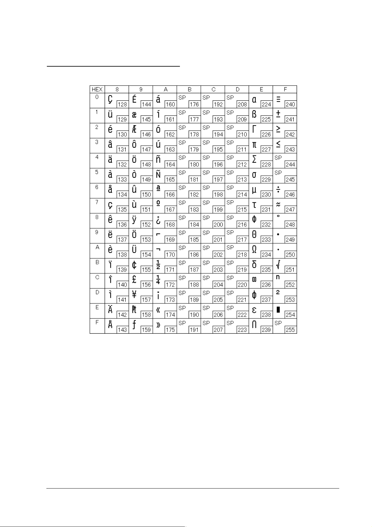
Page 0 (PC437: USA, Standard Europe)
TM-U330 Technical Reference Guide
Character Code Table A-2
Page 66

International Character Sets
A-3 Character Code Table
 Loading...