

Page 1
Describes how to control the printer and necessary information
when you develop applications.
Describes setup and installation of the product and peripherals.
Describes how to handle the product.
Describes general specifications and character code tables.
Describes features for the product.
Technical Reference Guide
Product Overview
Setup
Application Development Information
Handling
Appendix
M00091802
Rev. C
Page 2

Cautions
• No part of this document may be reproduced, stored in a retrieval system, or transmitted in any form or
by any means, electronic, mechanical, photocopying, recording, or otherwise, without the prior written
permission of Seiko Epson Corporation.
• The contents of this document are subject to change without notice. Please contact us for the latest
information.
• While every precaution has been taken in the preparation of this document, Seiko Epson Corporation
assumes no responsibility for errors or omissions.
• Neither is any liability assumed for damages resulting from the use of the information contained herein.
• Neither Seiko Epson Corporation nor its affiliates shall be liable to the purchaser of this product or third
parties for damages, losses, costs, or expenses incurred by the purchaser or third parties as a result of:
accident, misuse, or abuse of this product or unauthorized modifications, repairs, or alterations to this
product, or (excluding the U.S.) failure to strictly comply with Seiko Epson Corporation’s operating and
maintenance instructions.
• Seiko Epson Corporation shall not be liable against any damages or problems arising from the use of any
options or any consumable products other than those designated as Original Epson Products or Epson
Approved Products by Seiko Epson Corporation.
Trademarks
EPSON is a registered trademark of Seiko Epson Corporation.
Exceed Your Vision and ESC/POS are registered trademarks or trademarks of Seiko Epson Corporation.
®
Windows
countries.
microSD is registered trademarks of SD Card Association.
Wi-Fi
QR Code® is a registered trademark of DENSO Wave Incorporated.
AndroidTM is a trademark of Google Inc.
®
IOS
license.
All other trademarks are the property of their respective owners and used for identification purpose only.
is registered trademark or trademark of Microsoft Corporation in the United States and other
®
, WPATM, and WPA2TM are either registered trademarks or trademarks of Wi-Fi Alliance®.
is a trademark or registered trademark of Cisco in the U.S. and other countries and is used under
ESC/POS® Command System
Epson ESC/POS is a proprietary POS printer command system that includes patented or patent-pending
commands.
ESC/POS is compatible with most Epson POS printers and displays.
ESC/POS is designed to reduce the processing load on the host computer in POS environments. It comprises
a set of highly functional and efficient commands and also offers the flexibility to easily make future
upgrades.
© Seiko Epson Corporation 2015 - 2016. All rights reserved.
2
Page 3
For Safety
Key to Symbols
The symbols in this manual are identified by their level of importance, as defined below. Read the
following carefully before handling the product.
You must follow warnings carefully to avoid serious bodily injury.
WARNING
Provides information that must be observed to prevent damage to the equipment or loss of data.
Possibility of sustaining physical injuries.
CAUTION
Possibility of causing physical damage.
Possibility of causing information loss.
Provides information that must be observed to avoid damage to your equipment or a
malfunction.
Provides important information and useful tips.
3
Page 4

Warnings
WARNING
To avoid risk of electric shock, do not set up this product or handle cables during
a thunderstorm
Never insert or disconnect the power plug with wet hands.
Doing so may result in electric shock.
Handle the power cable with care.
Improper handling may lead to fire or electric shock.
Do not modify or attempt to repair the cable.
Do not place any heavy object on top of the cable.
Avoid excessive bending, twisting, and pulling.
Do not place the cable near heating equipment.
Check that the plug is clean before plugging it in.
Be sure to push the plug all the way in.
Do not use this product with any voltage other than the specified one. Doing so
may lead to fire or electric shock.
Do not place multiple loads on the power outlet.
Overloading the outlet may lead to fire.
Shut down your equipment immediately if it produces smoke, a strange odor, or
unusual noise.
Continued use may lead to fire. Immediately unplug the equipment and contact your
dealer or a Seiko Epson service center for advice.
Never attempt to repair this product yourself.
Improper repair work can be dangerous.
Never disassemble or modify this product.
Tampering with this product may result in injury or fire.
Do not allow foreign matter to fall into the equipment.
Penetration by foreign objects may lead to fire.
If water or other liquid spills into this equipment, do not continue to use it.
Continued use may lead to fire. Unplug the power cord immediately and contact your
dealer or a Seiko Epson service center for advice.
Do not use aerosol sprayers containing flammable gas inside or around this
product.
Doing so may cause fire.
4
Page 5

Cautions
CAUTION
Do not connect cables in ways other than those mentioned in this manual.
Different connections may cause equipment damage or fire.
Be sure to set this equipment on a firm, stable, horizontal surface.
The product may break or cause injury if it falls.
Do not use this product in locations subject to high humidity or dust levels.
Excessive humidity and dust may cause equipment damage or fire.
Do not place heavy objects on top of this product. Never stand or lean on this
product.
Equipment may fall or collapse, causing breakage and possible injury.
Take care not to injure your fingers on the manual cutter
When you remove printed paper
When you perform other operations such as loading/replacing roll paper
Do not open the roll paper cover without taking the necessary precautions, as this
can result in injury from the autocutter fixed blade.
To ensure safety, unplug this product before leaving it unused for an extended
period.
Do not knock or strike the printer. This may cause defective print.
Do not catch cables or place foreign matter under the printer.
The print head can be very hot during and immediately after printing. If you need
to touch it, such as for cleaning, wait until it cools down. Touching it before that
may cause burns.
Do not connect a telephone line to the drawer kick connector. There is a risk of the
telephone line or product being damaged.
When connecting external devices to the USB ports, follow the precautions below.
Confirm the rated current of the external devices by checking the descriptions on the
devices or manuals. Connect the external devices only when those total rated current
is less than 600 mA. Do not use a device whose rated current is unclear.
Use UL-approved external devices (only for North American users).
Restriction of Use
When this product is used for applications requiring high reliability/safety, such as transportation
devices related to aviation, rail, marine, automotive, etc.; disaster prevention devices; various safety
devices, etc.; or functional/precisio
consideration to including fail-safes and redundancies into your design to maintain safety and total
system reliability. B ec a use this product was not inten
high reliability/safety, such as aerospace equipment, main communication equipment, nuclear
power control equipment, or medical equipment related to direct medical care, etc., please make
your own judgment on this product's suitability aft
n devices, etc., you should use this product only after giving
ded for use in applications requiring extremely
er a full evaluation.
5
Page 6

About this Manual
Aim of the Manual
This manual aims to provide all the information necessary for the development, design, and
installment of POS systems, order entry systems, and other receipt issuing systems that use TM-
U220-i.
Manual Content
The manual is made up of the following sections:
Chapter 1
Chapter 2
Chapter 3
Chapter 4
Appendix
Product Overview
Setup
Application Development Information
Handling
Product Specifications
Option Specifications
Character Code Tables
6
Page 7

Contents
■ For Safety .............................................................................................................................. 3
Key to Symbols ....................................................................................................................................... 3
Warnings ................................................................................................................................................. 4
Cautions.................................................................................................................................................. 5
■ Restriction of Use.................................................................................................................. 5
■ About this Manual................................................................................................................ 6
Aim of the Manual ................................................................................................................................. 6
Manual Content .................................................................................................................................... 6
■ Contents................................................................................................................................ 7
Product Overview ........................................................................11
■ Features............................................................................................................................... 11
■ Product Configurations...................................................................................................... 13
Bundled items....................................................................................................................................... 13
Options.................................................................................................................................................. 13
■ Part Names and Functions ................................................................................................ 14
Power Switch ........................................................................................................................................ 14
Power Switch Cover............................................................................................................................. 14
Roll paper cover / Cover open lever................................................................................................. 15
Ribbon cassette cover ........................................................................................................................ 15
Control Panel........................................................................................................................................ 16
Interfaces.............................................................................................................................................. 17
Status LED.............................................................................................................................................. 19
Push Button ........................................................................................................................................... 19
Wired LAN Status LED........................................................................................................................... 20
Wireless LAN cable set (optional) LED............................................................................................... 20
■ Online and Offline..............................................................................................................21
Online .................................................................................................................................................... 21
Offline .................................................................................................................................................... 21
■ Error Status........................................................................................................................... 22
Automatically Recoverable Errors...................................................................................................... 22
Recoverable Errors............................................................................................................................... 22
Unrecoverable Errors ........................................................................................................................... 23
Setup .............................................................................................25
■ Flow of Setup ...................................................................................................................... 25
■ Installing the Product ......................................................................................................... 30
Hanging the Printer on a Wall............................................................................................................. 31
■ Changing the Paper Width................................................................................................ 43
■ Adjusting the Paper Roll Near-End Sensor ....................................................................... 46
■ Installing the microSD Card............................................................................................... 49
■ Connecting the Product to the Network.......................................................................... 50
7
Page 8

For Wired LAN connection ..................................................................................................................50
For Wireless LAN Interface ...................................................................................................................50
■ Connecting the Peripherals .............................................................................................. 53
Connecting the Customer Display.....................................................................................................53
Connecting the Serial Communication Device ............................................................................... 54
Key Input Device via a USB Interface.................................................................................................54
Connecting the Cash Drawer.............................................................................................................55
■ Connecting the AC Adapter............................................................................................. 57
■ Attaching the Power Switch Cover ................................................................................... 58
■ Setting the DIP Switches..................................................................................................... 59
Functions ...............................................................................................................................................59
Setting Procedure.................................................................................................................................61
■ Setting the Memory Switches............................................................................................ 62
Memory Switch 2 ..................................................................................................................................62
Memory Switch 8 ..................................................................................................................................62
Customize value ...................................................................................................................................63
Memory Switch Setup Mode...............................................................................................................64
■ Network Setting .................................................................................................................. 65
Confirming Network Setting ................................................................................................................67
Initializing the Network Setting ............................................................................................................68
■ Enabling PHP....................................................................................................................... 70
■ Enabling HTTPS Communication....................................................................................... 71
■ Settings for Server Direct Print ........................................................................................... 72
■ Settings for Connected Devices ....................................................................................... 73
■ Registering Web Contents................................................................................................. 75
Creating Web Contents ......................................................................................................................75
Specifications for when PHP is enabled.............................................................................................76
Verifying the integrity of Web contents with md5 files .....................................................................77
Certificate files ......................................................................................................................................77
Registering Web Contents...................................................................................................................78
■ Settings for Spooler............................................................................................................. 80
■ Settings for Print Forwarding .............................................................................................. 81
■ Settings for Device Data Notification ............................................................................... 82
Application Development Information...................................... 83
■ Controlling the Printer ........................................................................................................ 83
Epson ePOS SDK ...................................................................................................................................84
ePOS-Device XML.................................................................................................................................85
ePOS-Print XML......................................................................................................................................87
Server Direct Print .................................................................................................................................89
Device Data Notification.....................................................................................................................90
Web Server............................................................................................................................................91
Spooler and Print Forwarding..............................................................................................................92
■ Software and Manuals....................................................................................................... 95
How to Get Manuals and Software....................................................................................................96
■ EPSON TMNet WebConfig.................................................................................................. 97
8
Page 9

Starting EPSON TMNet WebConfig..................................................................................................... 97
Help Screen Display ............................................................................................................................. 97
Version Screen Display ........................................................................................................................ 97
General Information ............................................................................................................................ 98
Information - Wired - TCP/IP................................................................................................................ 99
Information - Wireless - TCP/IP ............................................................................................................ 99
Information - Web Contents ............................................................................................................. 100
Information - Time .............................................................................................................................. 100
Web Service Settings - Device Admin - Printer ............................................................................... 101
Web Service Settings - Device Admin - Customer Display............................................................ 102
Web Service Settings - Device Admin - Key Input Device ............................................................ 103
Web Service Settings - Device Admin - Serial Communication Device...................................... 103
Web Service Settings - Device Admin - Search Printer.................................................................. 104
Web Service Settings - Spooler - Settings ........................................................................................ 104
Web Service Settings - Spooler - Print forwarding .......................................................................... 105
Web Service Settings - Web Contents - Update Settings .............................................................. 106
Web Service Settings - Server Access - Direct Print........................................................................ 107
Web Service Settings - Server Access - Status Notification ........................................................... 108
Web Service Settings - Server Access - Device Data Notification ............................................... 109
System Settings - Network - Wired .................................................................................................... 110
System Settings - Network - Wired - TCP/IP...................................................................................... 110
System Settings - Network - Wireless................................................................................................. 111
System Settings - Network - Wireless - TCP/IP .................................................................................. 112
System Settings - Network - Security - Server Authentication ....................................................... 112
System Settings - Network - Security - SSL ........................................................................................ 113
System Settings - Proxy - Proxy .......................................................................................................... 114
System Settings - Time - Time ............................................................................................................ 114
Admin Settings - Maintenance - Reset............................................................................................ 115
Admin Settings - Administrator Information - Administrator .......................................................... 115
Admin Settings - Administrator Information - Password ................................................................. 115
PHP settings......................................................................................................................................... 116
■ Status sheet....................................................................................................................... 117
■ Settings Confirmation Mode ........................................................................................... 123
Self-test Mode .................................................................................................................................... 123
Hexadecimal Dumping Mode ......................................................................................................... 124
■ Easy Setup......................................................................................................................... 125
■ Checking/Updating TM-i Firmware ................................................................................ 126
Checking the TM-i Firmware Version................................................................................................ 126
Updating TM-i Firmware .................................................................................................................... 126
Handling .....................................................................................127
■ Installing/Replacing the Ribbon Cassette ..................................................................... 127
■ Installing/Replacing the Roll Paper................................................................................ 131
■ Removing a Paper Jam................................................................................................... 134
■ Adjusting the Auto cutter blade ..................................................................................... 135
■ Cleaning the Printer Case ............................................................................................... 136
■ Preparing for Transport..................................................................................................... 136
9
Page 10

Appendix.................................................................................... 137
■ Product Specifications..................................................................................................... 137
Software Specifications .....................................................................................................................139
Controllable Peripherals ....................................................................................................................140
Printing Specifications ........................................................................................................................141
Character Specifications...................................................................................................................142
Printable Area .....................................................................................................................................143
Paper Specifications ..........................................................................................................................146
Ribbon Specifications ........................................................................................................................147
Electrical Characteristics ...................................................................................................................147
Environmental Conditions..................................................................................................................148
External Dimensions and Mass ..........................................................................................................149
AC Adapter.........................................................................................................................................149
■ Option Specifications ...................................................................................................... 150
Wireless LAN Cable Set (OT-WL01)....................................................................................................150
Customer Display (DM-D110) ............................................................................................................150
■ Character Code Tables ................................................................................................... 150
10
Page 11

Chapter 1 Product Overview
Product Overview
This chapter describes features of the product.
Features
TM-U220-i is a receipt printer which can print directly from a smart device application or Web
application.
*1
This product supports ePOS-Device
peripherals or network compatible TM printers.
*1: ePOS-Device: Epson original technology to control TM printers or POS peripherals via a smart
device application or Web application. This technology is realized by ePOS-Device Service
running on the products.
and ePOS-Print *2 and are capable of controlling POS
1
*2: ePOS-Print: Epson original printing function t
systems supported by XML and Web services. This technology is realized by the ePOS-Print
Service running on the products.
hat has a high compatibility with a variety of
11
Page 12

Functions
•Enables connection to peripherals (customer displays, barcode scanners, etc) via a USB or serial
interface.
•The Epson ePOS SDK is provided for iOS, Android and Windows application, and Web
application development.
The Epson ePOS SDK is a software development kit that integrates the ePOS-Print SDK and the
ePOS-Device SDK. It is recommended
SDK is migrated to the Epson ePOS SDK. For detail, refer to the Migration Guide included with
the Epson ePOS SDK.
*1
• Uses the communication box
function to enable communications between applications. This
function allows for communications, etc. between tablet terminals. (ePOS-Device SDK,
ePOS-Device XML)
•Supports Server Direct Print that sends a request for print data from the product to the Web server
at regular
intervals.
•Since print data can be saved in the spooler, applications can be released from processing print
jobs regardless of the printer status.
•When a network printer is registered, print forwarding process can be realized. Also, if the printer
is not ready to print, you can print from another printer.
that application software developed with the ePOS-Device
•Device data notification function is realized, allowing for notifications to be sent from devices
such as barcode scanners to Web servers to trigger applications.
•Equipped with Web server that supports the scripting language "PHP" and database "SQLite3".
•Enables HTTPS communication.
•Supports TLS1.2. SSL3.0 is not supported.
*2
*3
*1: For more information on the communication box, see the Epson ePOS SDK User's Manual, and
the ePOS-Device XML User's Manual.
*2: TM-i firmware Ver. 4.3 or later.
*3: TM-i firmware Ver. 4.4 or later.
For information on how to use these functions. (U "Controlling the Printer" on page 83)
12
Page 13

Product Configurations
Bundled items
•AC adapter (Model: PS-180)
•AC cable *
• Roll paper (for operation check)
•Ribbon cassette (Model: ERC-38)
•Start Here
•Manual CD
•Power switch cover
* May vary based on specifications and region.
Chapter 1 Product Overview
1
Options
• Roll paper near-end sensor (Factory option)
•Affixing tape for fixing the printer (Model: DF-10)
• Wall-hanging bracket (Model: WH-10)
•Power supply box (Model: OT-BX220)
•Wireless LAN cable set (Model: OT-WL01)
•Customer display (Model: DM-D110)
13
Page 14
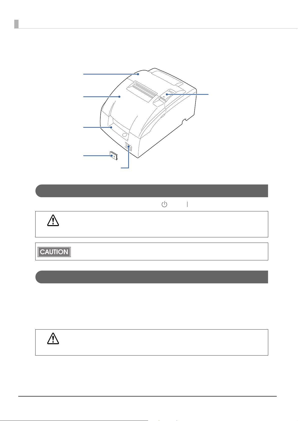
Part Names and Functions
Roll paper cover
Ribbon cassette cover
Control panel
Power switch cover
Cover open lever
Power switch
Power Switch
Turns the printer on or off. The marks on the switch: ( : OFF/ : ON)
CAUTION
Power Switch Cover
Install the power switch cover that comes with the TM-U220-i onto the printer to prevent
inadvertent changing of the power switch, to prevent tampering, and to improve the appearance of
the printer.
To ope r a te the power switch, insert an object with a pointed tip such as a ballpoint pen into the hole
on the power switch cover.
WARNING
Before turning on the product, be sure to check that the AC adapter is connected to the
power supply.
After the product is turned on, it requires about 30 seconds until it is ready to print.
If an accident occurs with the power switch cover attached, unplug the power cord
immediately.
Continued use of the printer may cause fire or electric shock.
14
Page 15
Chapter 1 Product Overview
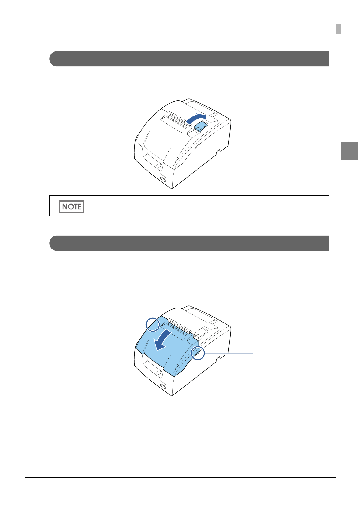
Catches (both sides)
Roll paper cover / Cover open lever
When setting or replacing the roll paper, use the cover open lever to open the roll paper cover.
Pull the cover open lever to open the roll paper cover.
Do not open the roll paper cover during printing or while the autocutter is operating.
1
Ribbon cassette cover
When installing or replacing the ribbon cassette, open the ribbon cassette cover by lifting up the
catches on both sides of the cover.
Put your fingers under the catches on both sides and lift the ribbon cassette cover in the direction of
the arrow to open it.
15
Page 16
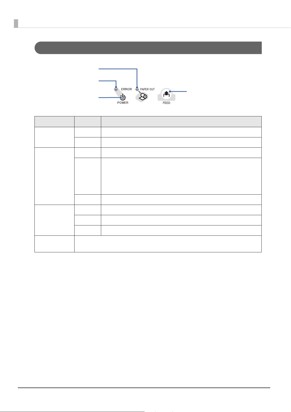
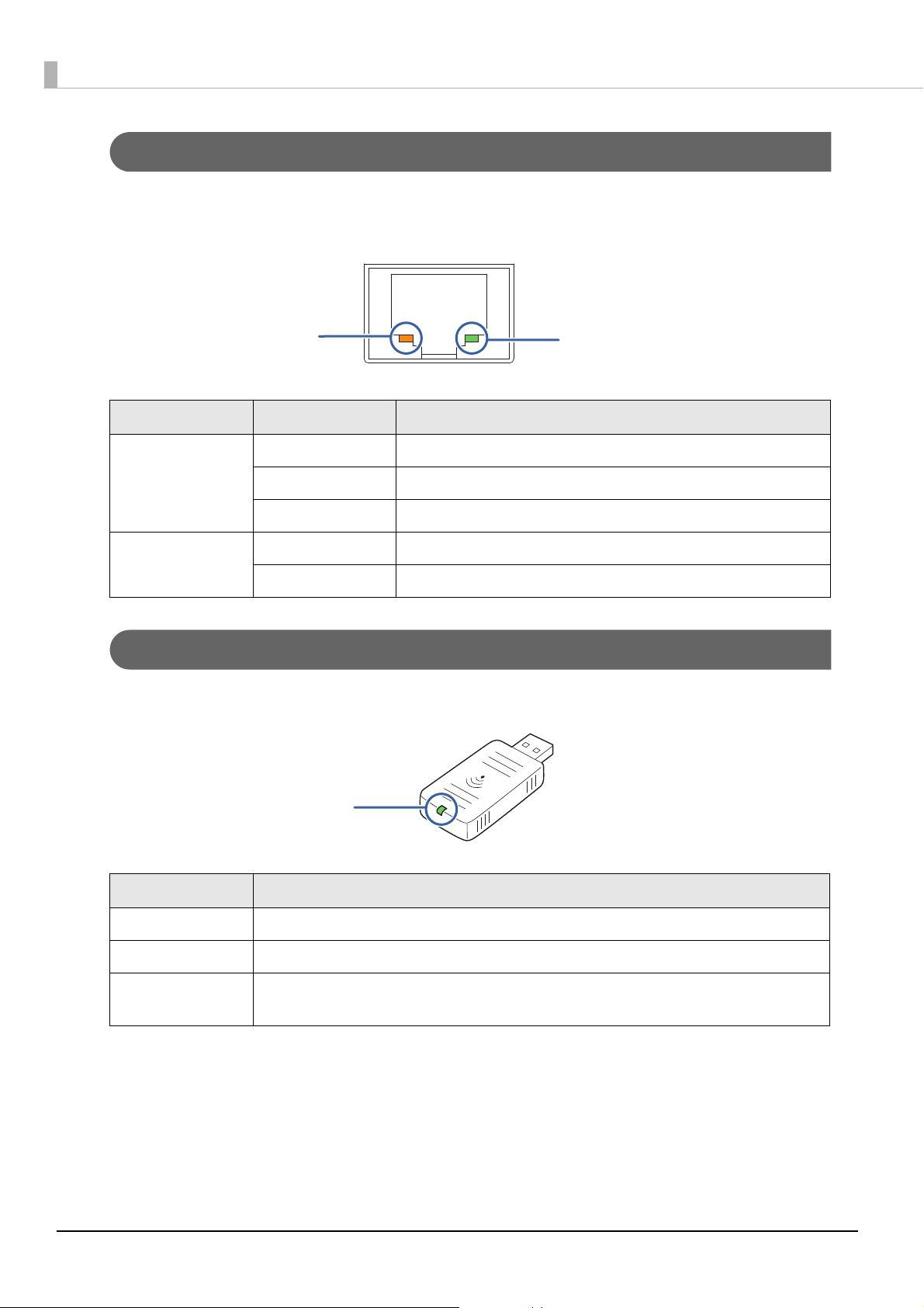
Control Panel
POWER LED
ERROR LED
PAP E R OU T L ED
FEED button
Name Status Description
POWER LED On Power is being supplied.
Off Power is not being supplied.
ERROR LED Off Normal operation (online)
On Immediately after the power is turned on or immediately after a reset
(offline).
Automatically goes off after a while to indicate that the printer is ready.
The end of the roll paper is detected, and when printing has stopped
(offline). If this happens, replace the roll paper.
Flashing An error has occurred (U
PAPER OUT LED Off There is a sufficient amount of roll paper remaining.
On There is little or no roll paper remaining.
Flashing A self-test printing standby state and macro execution standby state
FEED button Pressing this button once feeds the roll paper by one line. Holding this button down
feeds the roll paper continuously.
"Error Status" on page 22)
16
Page 17
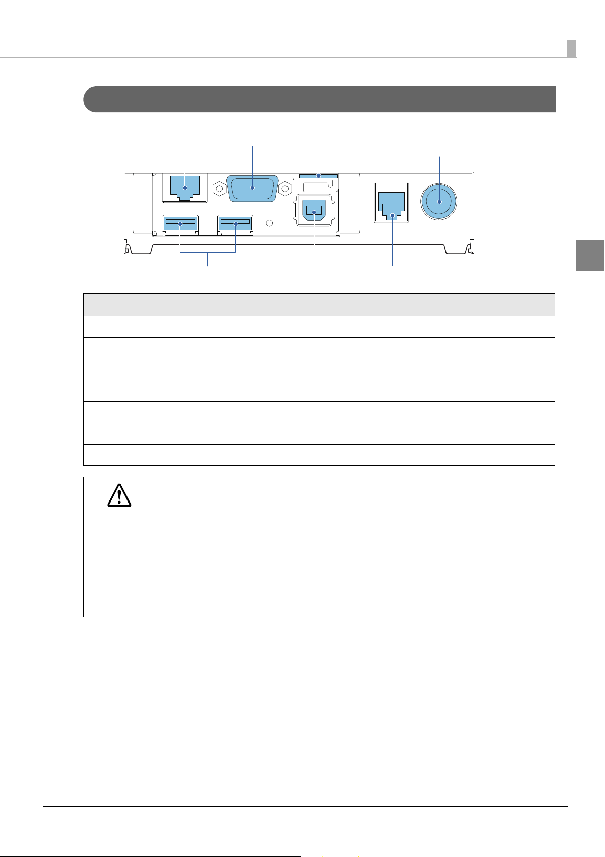
Interfaces
Serial port
Ethernet port
microSD card slot
DC-in connector
USB host ports
USB device port
Drawer kick connector
Name Description
Drawer kick connector Connects a cash drawer.
Chapter 1 Product Overview
1
Ethernet port Connect the LAN cable here to connect to the network.
USB host port (Type A) Connects peripherals via a USB interface.
USB device port (Type B) Connects a computer.
DC-In connector Connects a AC adapter.
microSD card slot Used when using the PHP function.
Serial port Connects a serial communication device.
When connecting USB interface devices, make sure to check the devices or manuals,
etc. for current consumption. The total value should be 600 mA or less. Never use
CAUTION
devices that provide no information on current consumption.
When connecting the USB cables, pass the cables through the cable band to prevent
them from coming off.
Make sure that the protective cover is securely fit into place while the product is oper-
ating.
For Ethernet ports, make sure that the outdoor aerial LAN cables are connected
through a surge protector. Failure to do so may lead to device error resulting from
indirect lightning.
17
Page 18
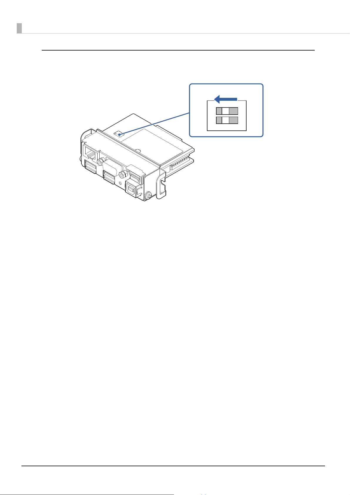
DIP switch
Turn both DIP switches SW-1 and SW-2 of the intelligent I/F board OFF.
OFF
1
O
N
2
18
Page 19
Chapter 1 Product Overview
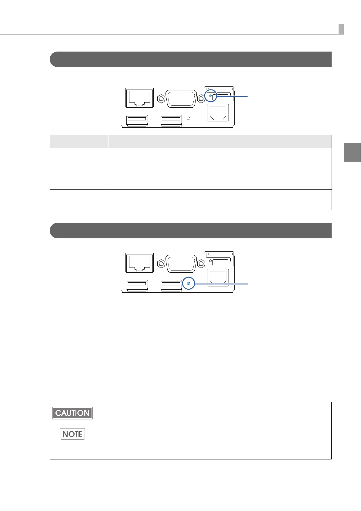
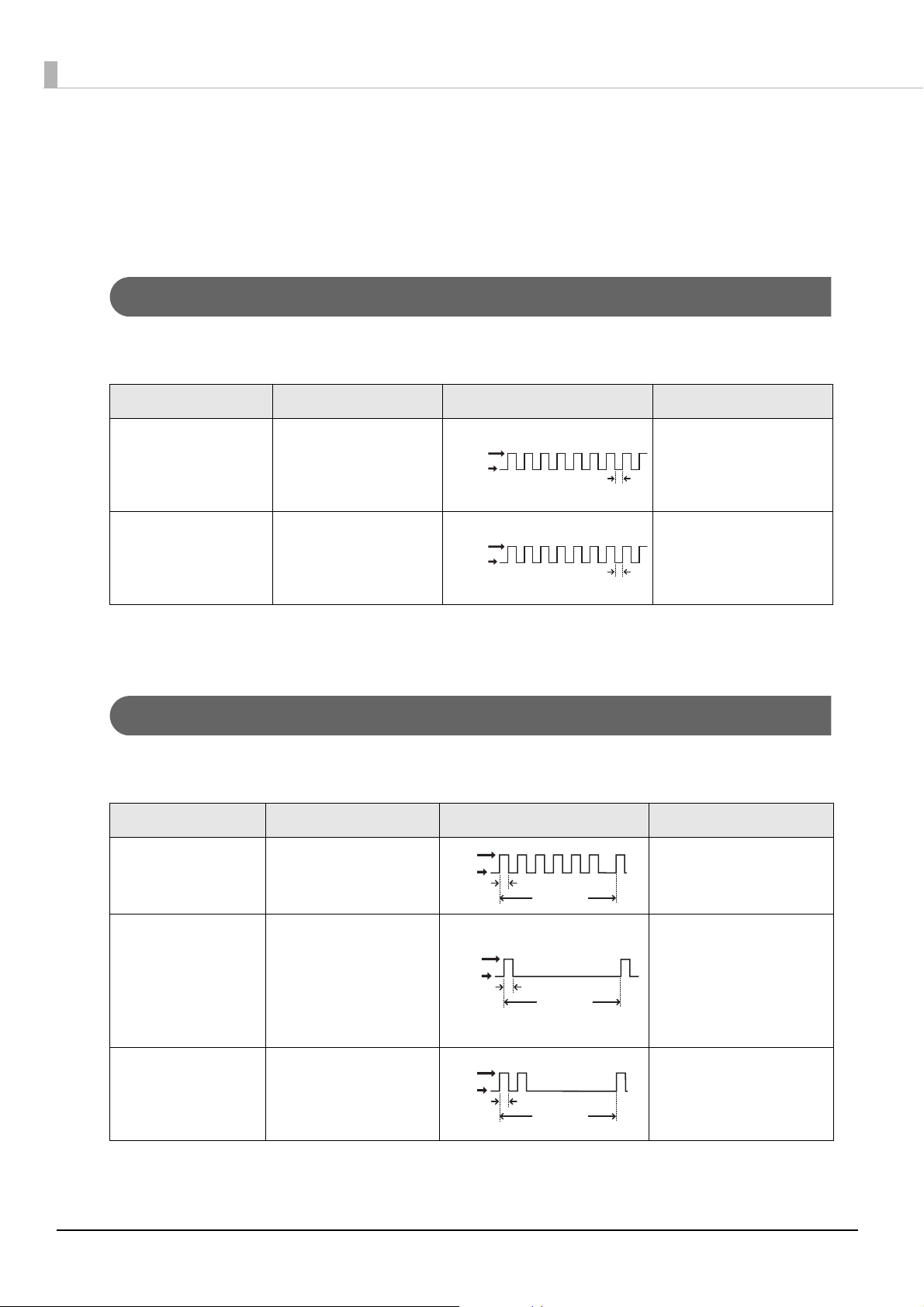
Status LED
Push button
Status LED
With the status LED on the rear of the product, you can check the interface board status.
LED Description
On (Green) Operating normally.
On (Orange) Starting up.
If the status LED is on in orange even after 30 seconds have passed since the
printer is turned on, repair is required.
Off Power is not turned on.
If the status LED is off even if the printer is turned on, repair is required.
Push Button
Press the push button with a thin object such as a tweezers.
The push button has the following functions:
•Status sheet printing:
Make sure the product is turned on, press the push button for approximately 3 seconds. When you
release the button, a status sheet on which ne
(U "Confirming with a status sheet" on page 67.)
twork parameters are printed will be ejected.
1
•Initialization:
Make sure the product is turned on, press the push button for approximately 10 seconds. When
you release the button, network setting (Wired LAN/ Wireless LAN) will be initialized.
"Initializing the Network Setting" on page 68.)
(U
To print a status sheet, release the push button within 10 seconds. If the button is kept down for
10 seconds or more, the network setting will be initialized.
Press the push button after the status LED color has changed from orange to green. After
the printer is turned on, it takes about 20 to 30 seconds until the status LED color changes to
green.
Even if the button is pressed while the status LED is on in orange, the button will not operate.
19
Page 20
Wired LAN Status LED
LED (Green)
LED (Yellow)
LED (Green)
With the Wired LAN Status LED on the rear of the product, you can check the communication status
of the product.
LED Status Description
Green On Link established
Flashing Transmitting/receiving data
Off Link not established
Yellow On 100BASE-TX
Off 10BASE-T
Wireless LAN cable set (optional) LED
With the LED on the wireless LAN unit, you can check the communication status of the product.
LED Description
Off The wireless LAN unit is not connected to the product. Or the product power is OFF.
Flashing This wireless LAN unit is connected to the product and is in operation.
Flashing rapidly
This wireless LAN unit is connected to the product and is in operation.
This unit is communicating on a network.
20
Page 21

Chapter 1 Product Overview
Online and Offline
Online
When no events to go offline have occurred, the printer is online and ready for normal printing.
Offline
The printer automatically goes offline under the following conditions:
•During power on (including resetting with the interface) until the printer is ready
•During the self-test
•When the roll paper cover is open.
•When the ribbon cassette cover is open.
•While roll paper is fed using the FEED button.
•When printing stops due to end of paper. (When the roll paper end sensor detects the end of paper
or the printer is set so that printing stops upon detection of roll paper near-end.)
• Macro execution standby state
•When an error has occurred
1
21
Page 22
Error Status
LED ON
LED OFF
Approx. 160 ms
LED ON
LED OFF
Approx. 160 ms
LED ON
LED OFF
Approx. 160 ms
Approx. 2560 ms
LED ON
LED OFF
Approx. 160 ms
Approx. 2560 ms
LED ON
LED OFF
Approx. 160 ms
Approx. 2560 ms
There are three possible error types: automatically recoverable errors, recoverable errors, and
unrecoverable errors. Check the error LED flash code.
When connection to peripherals fails, check the status LEDs at the lower rear of the product.
Automatically Recoverable Errors
Printing is no longer possible when automatically recoverable errors occur. They can be recovered
easily, as described below.
Error Error description Error LED flash code Recovery measure
Roll paper cover
open error
(when recoverable
The roll paper cover
was opened during
printing.
Recovers automatically
when the roll paper
cover is closed.
error is selected) (*1)
Print head
temperature error(*2)
A high temperature
outside the head
drive operating range
Recovers automatically
when the print head
cools.
was detected.
(*1) This conditions are selected by MSW 8-5, 8-8. When MSW 8-5 (mapping of the cover open status) is off, the error has
not occurred but there is a “paper end error” instead. If MSW 8-8 is off, this error is handled as an automatically
recoverable error.
(* 2) Print head temperature error is not abnormal.
Recoverable Errors
Printing is no longer possible when recoverable errors occur. They can be recovered easily by turning
the power on again after eliminating the cause of the error.
Error Error description Error LED flash code Recovery measure
Paper roll cover
open error (*1)
The roll paper cover is
opened when printing.
Recovers by error
recovery command
with the cover closed
Autocutter error Autocutter does not
work correctly.
Remove the jammed
paper or foreign matter
in the printer, close the
roll paper cover, and
then turn the power on
to recover.
Home position
detection error
(This is “Mechanical
The home position
cannot be detected
due to a paper jam
Recovers by error
recovery command
error“)
(*1) These conditions are selected by MSW 8-5 and 8-8. When MSW 8-5 (mapping of the cover open status) is OFF, the
error does not occur and a “paper end error” occurs instead. If MSW 8-8 is ON, this error is handled as a recoverable
error.
22
Page 23
Chapter 1 Product Overview
LED ON
LED OFF
Approx. 160 ms
LED ON
LED OFF
Approx. 160 ms
LED ON
LED OFF
Approx. 160 ms
LED ON
LED OFF
Approx. 160 ms
LED ON
LED OFF
Approx. 160 ms
Approx. 2560 ms
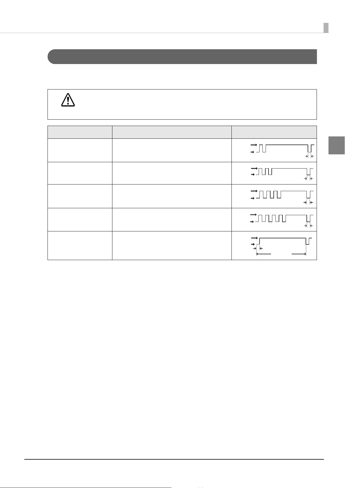
Unrecoverable Errors
If the same error occurs again even after turning the power back on, contact your dealer or a Epson
service center.
Turn off the power immediately when unrecoverable errors occur.
CAUTION
Error Error description Error LED flash code
Memory R/W error After R/W checking, the printer does not
work correctly.
High voltage error The power supply voltage is extremely high.
Low voltage error The power supply voltage is extremely low.
CPU execution error The CPU is executing an incorrect address.
Internal circuit
Internal circuits are not connected correctly.
connection error
1
23
Page 24

24
Page 25
Chapter 2 Setup
Setup
This chapter describes the installation and setup procedure of the product and peripherals required
to use the product.
Yo u can utilize "Easy Setup", which en ables settings to the TM-i to be made in a simple manner using
a USB memory that contains a file of EPSON TMNet WebConfig setting values.
For detail, refer the “TM-i series Easy Setup Guide”.
Flow of Setup
The setting items are different depending on the system to be used. Check the items by referring to
"Controlling the Printer" on page 83.
•Epson ePOS SDK, ePOS-Device XML, ePOS-Print XML (U
•Server Direct Print (U page 27)
•Device Data Notification (U page 28)
•Using This Product as a Web Server (U
This chapter consists of the following sections along with the setup flow of the product and
peripherals.
In this setup flow, necessary items are in a frame with a solid line. Optional items are explained
in an frame with a dotted line.
page 29)
page 26)
2
25
Page 26
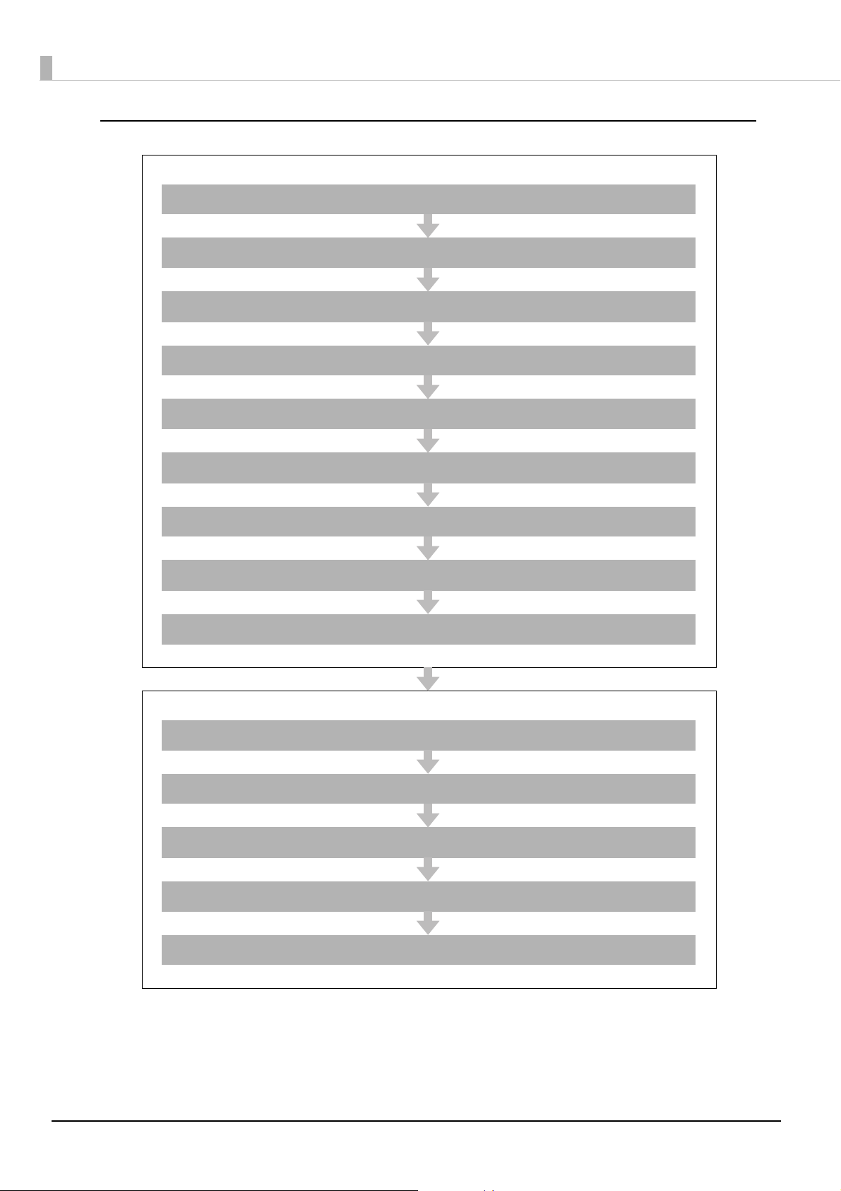
Epson ePOS SDK, ePOS-Device XML, ePOS-Print XML
Settings for Printer
Installing the Product ( page 30)
Changing the Paper Width ( page 43)
Adjusting the Paper Roll Near-End Sensor ( page 46)
Connecting the Product to the Network ( page 50)
Connecting the Peripherals ( page 53)
Connecting the AC Adapter ( page 57)
Attaching the Power Switch Cover ( page 58)
Setting the DIP Switches ( page 59)
Setting the Memory Switches ( page 62)
Settings for EPSON TMNet WebConfig
Network Setting ( page 65)
Enabling HTTPS Communication ( page 71)
Settings for Connected Devices ( page 73)
Settings for Spooler ( page 80)
Settings for Print Forwarding ( page 81)
26
Page 27
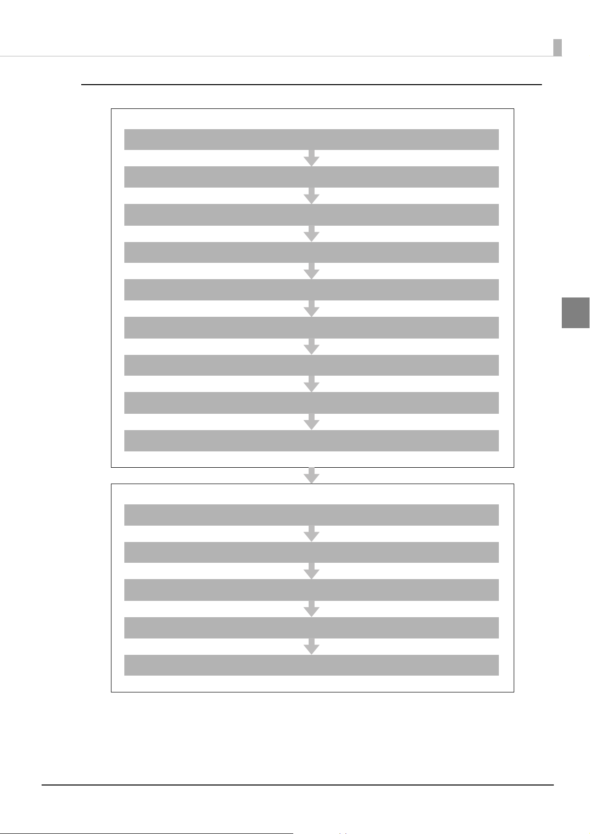
Server Direct Print
Settings for Printer
Installing the Product ( page 30)
Changing the Paper Width ( page 43)
Adjusting the Paper Roll Near-End Sensor ( page 46)
Connecting the Product to the Network ( page 50)
Connecting the Peripherals ( page 53)
Chapter 2 Setup
Connecting the AC Adapter ( page 57)
Attaching the Power Switch Cover ( page 58)
Setting the DIP Switches ( page 59)
Setting the Memory Switches ( page 62)
Settings for EPSON TMNet WebConfig
Network Setting ( page 65)
Settings for Server Direct Print ( page 72)
Settings for Connected Devices ( page 73)
2
Settings for Spooler ( page 80)
Settings for Print Forwarding ( page 81)
27
Page 28
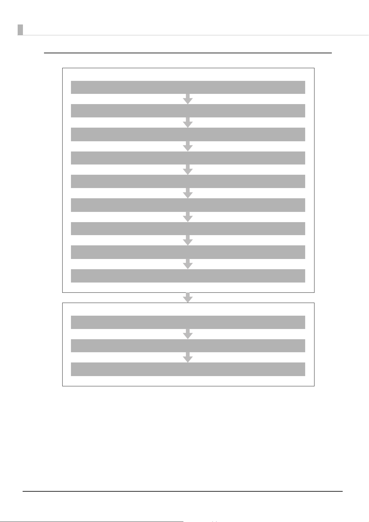
Device Data Notification
Settings for Printer
Installing the Product ( page 30)
Changing the Paper Width ( page 43)
Adjusting the Paper Roll Near-End Sensor ( page 46)
Connecting the Product to the Network ( page 50)
Connecting the Peripherals ( page 53)
Connecting the AC Adapter ( page 57)
Attaching the Power Switch Cover ( page 58)
Setting the DIP Switches ( page 59)
Setting the Memory Switches ( page 62)
Settings for EPSON TMNet WebConfig
Network Setting ( page 65)
Settings for Connected Devices ( page 73)
Settings for Device Data Notification ( page 82)
28
Page 29
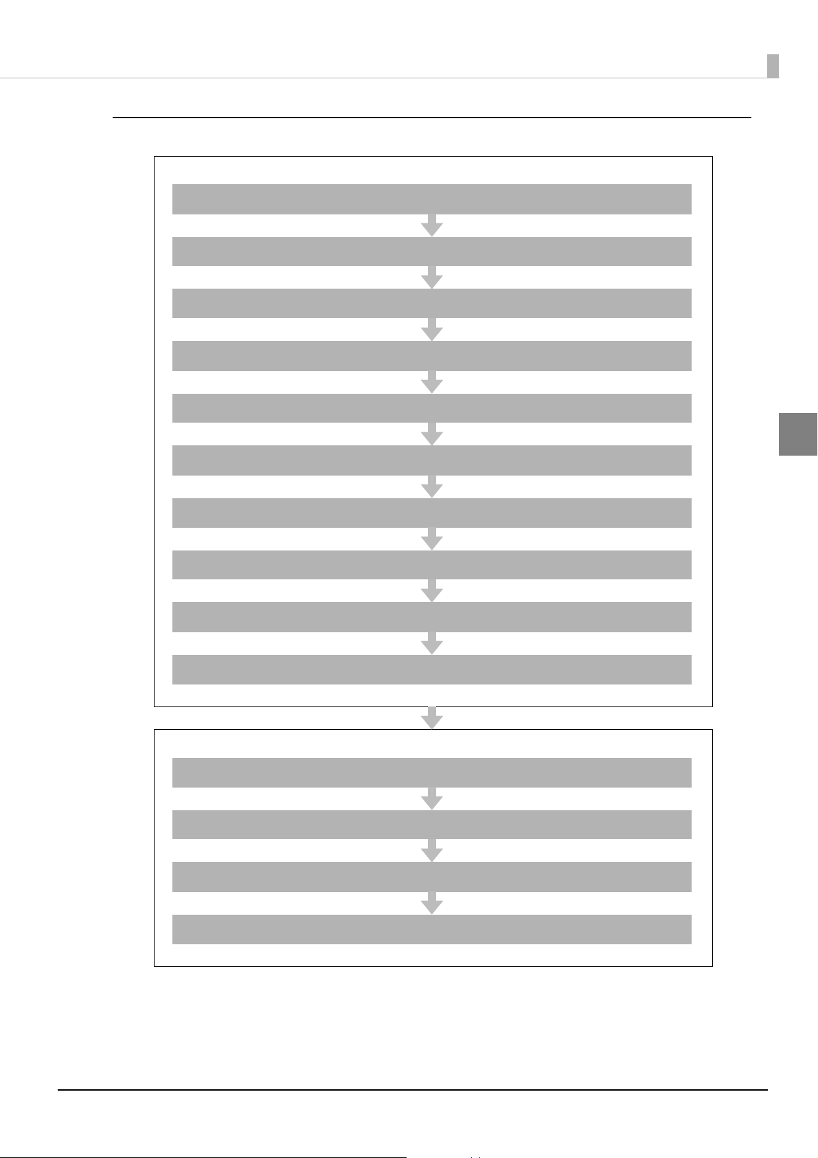
Using This Product as a Web Server
Settings for Printer
Installing the Product ( page 30)
Changing the Paper Width ( page 43)
Adjusting the Paper Roll Near-End Sensor ( page 46)
Installing the microSD Card ( page 49)
Connecting the Product to the Network ( page 50)
Connecting the Peripherals ( page 53)
Chapter 2 Setup
2
Connecting the AC Adapter ( page 57)
Attaching the Power Switch Cover ( page 58)
Setting the DIP Switches ( page 59)
Setting the Memory Switches ( page 62)
Settings for EPSON TMNet WebConfig
Network Setting ( page 65)
Enabling HTTPS Communication ( page 71)
Enabling PHP ( page 70)
Registering Web Contents ( page 75)
29
Page 30
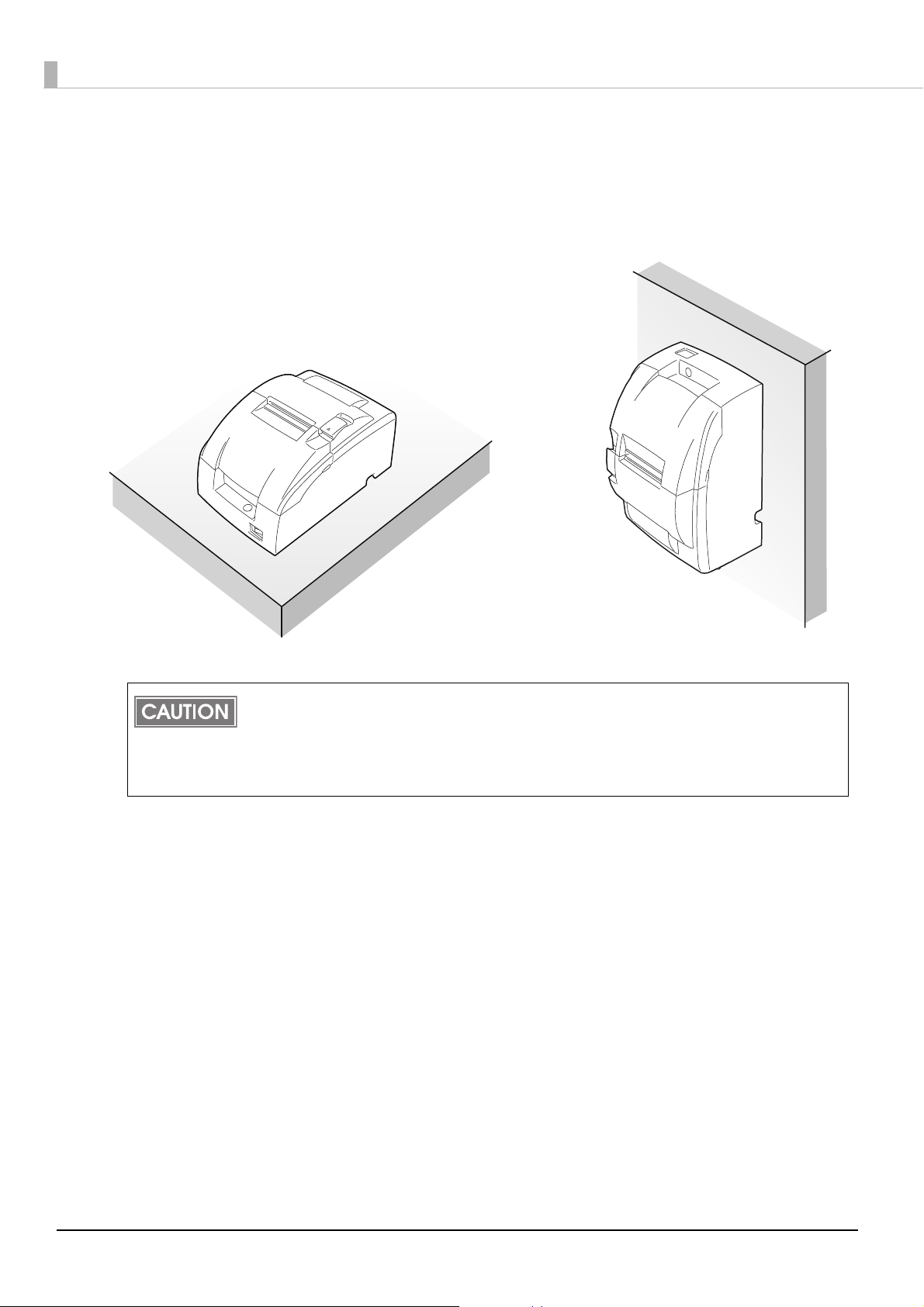
Installing the Product
Horizontal Installation Hanging Installation
Yo u can install the printer horizontally on a flat surface (with the paper exit on top). Also, you can
hang it on a wall using the included accessories.
Take measures to prevent the printer from moving by vibration during paper cutting and
when using a drawer. Affixing tape (Model: DF-10) is provided as an option.
Do not place the printer in dusty locations.
Do not knock or strike the printer. This may cause defective print.
Do not catch cables or foreign matter under the printer.
30
Page 31

Chapter 2 Setup
control panel label
Hanging the Printer on a Wall
To hang the printer on the wall, follow the steps below.
Before installation, be sure that the printer and all equipment connected to the printer is turned off.
Detach all cables from the body of the printer.
Static electricity may cause cut paper to adhere to the printer case. This static electricity will not
affect the operation of the printer.
Affixing the operation panel sheet
Attach the included control panel label for vertical installation on the roll paper cover.
2
Changing the roll-paper detector position
Two types of screws are used with the WH-10: 3×6 and 3×10. The longest screw (3×12) will not be
used.
Open the roll paper cover.
1
For a model that does not have a roll-paper near-end detector and does not need a change in
paper width, jump to step 7. For a model that does not have a roll-paper near-end detector and
needs a change in paper width, jump to step 3
31
Page 32

Loosen the detector adjustment screw a little bit by using a tool such as a
Detector adjustment screw
Roll paper guide
2
coin and then loosen the screw gently by hand as until it stops. It must not
be removed completely.
Remove the two screws of the roll paper guide.
3
For a model that does not have a roll-paper near-end detector, jump to step 6.
32
Page 33

Rotate the detector lever on the roll paper guide to change its direction.
Detector lever
Cable
Detector adjustment screw
4
After the direction of the detector lever is changed, be sure that the cable is connected to the
connector firmly.
Chapter 2 Setup
2
Tighten the detector adjustment screw.
5
33
Page 34

Align the hole on the roll paper guide with the hole on the roll paper holder
Roll paper guide
76mm
70mm
58mm
Dowel
Roll paper holder for
hanging bracket
Hole
6
to match your roll paper width and then tighten the screw (3×10).
You will not use one of the two screws that have been removed when the roll paper guide is
removed. Please store it as an extra screw in case you need it.
Align the hole on the roll paper holder for hanging bracket with the dowel
7
on the roll paper guide. (For a model that needs a change of paper width,
the hole to be used will be different to match your roll paper width.)
Putting the screw (3×6) in the hole on the roll paper holder for hanging bracket makes it easier
for you to tighten the screw in the next step.
34
Page 35

Tighten the screw (3×6) to fix the roll paper holder for hanging bracket and
8
the base frame.
Chapter 2 Setup
2
Tighten the screw (3×10) to fix the roll paper holder for hanging bracket and
9
the roll paper holder.
35
Page 36

Check that the brake arm is up.
OK
NG
brake arm
Dowel
Hole
Platen frame
10
Do not move the brake arm until the roll paper holder for hanging bracket is attached onto the
base frame. Otherwise the arm part will be damaged.
Insert the dowel of the cam into the hole of the platen frame.
11
36
Page 37

While you make sure the pin of the brake arm is in the groove on the inner
Pin of brake arm
12
side of the cam, rotate the cam along with the surface of the platen frame
in the direction indicated by the arrow until it clicks into position.
Chapter 2 Setup
2
Close the printer cover.
13
37
Page 38

Removing the cam
While you push the cam through the hole on the platen frame with a pointed tool such as
tweezers, rotate the cam in the upper direction to remove it.
2
1
38
Page 39

Installing the brackets
Fold this part inside and insert it into
holes to assemble the package.
2
1
Turn the printer over and then put it on a packing box as a platform
1
horizontally.
Chapter 2 Setup
2
Attach the upper bracket to the holes numbered “2” and the lower bracket
2
to the holes numbered “1”using the screws (3×6).
Four different sets of screw holes are found on each bracket. Each hole is identified by a
number; be sure to use the holes indicated in the instructions.
39
Page 40

Installing the wall-mount
A
48 mm
4 mm
12 mm or more
10 mm or more
84 mm
Attach the wall-mount to the wall in the position illustrated to the right (with the area marked A at
the top), and fasten securely with ten screws. These screws are not included; please use screws
appropriate to the type of wall being used.
Before attaching the wall-mount, make sure enough space remains around the printer.
To fix the printer securely, install the wall hanging bracket on a wall made of wood, concrete,
or metal. The thickness of the wall should be 10 mm {0.4"} or more.
In order to insure that the wall-mount can properly support the weight of the printer, please
secure it with screws appropriate to the type of wall the wall-mount is installed on.
A screw with 4 mm diameter and length of 12 mm or more is recommended. The thickness
of the wall should be 10 mm or more.
Be sure to use metallic screws.
The screws on the wall side must have a pull-out strength of 150 N (15.3 kgf) or more.
Be sure to fasten the wall-mount securely to the wall with a screw in each of the ten holes.
40
Page 41

Mounting the printer on the wall
Slide the brackets into the slots of the wall-mount, starting with the top bracket.
Chapter 2 Setup
2
When mounting the printer, make sure that the wall-mount is securely fastened to the wall.
41
Page 42

Setting the “Right side up printing”
“Right side up printing“ is a printing mode used for printers installed on a wall.
Turn on the setting for DIP switch 1-1 (U "Setting the DIP Switches" on page 59
For details about this mode, refer to Guide for TM-U220 right side up printing (U
Manuals" on page 95).
123456789...
ABCDEFG...
ABCDEFG...
123456789...
).
"Software and
Normal printing mode
Right side up printing mode
When you install the right side up mode printer into your system (application program), you
may need to modify the program.
The right side up printing mode requires DIP switch 1-2 (receive buffer: 4KB) to be turned off.
"Setting the DIP Switches" on page 59)
(U
42
Page 43

Changing the Paper Width
Leading the wires between
the holder and frame
Roll paper guide
Roll paper holder
The TM-U220-i accommodates 76 mm {3"},69.5 mm {2.74"}, 57.5 mm {2.26"} wide paper rolls.
Follow the steps below to change the paper width.
When changing the paper width, be sure to make the setting for the paper width with the
memory switch. (U
When you use a near-end detector equipped model, be sure not to pinch the lead wires of
the near-end detector between the roll paper guide and the roll paper holder, and to push the
lead wires inside so that the lead wire of the paper-end detector does not contact the motor
gear.
"Setting the Memory Switches" on page 62)
Chapter 2 Setup
2
43
Page 44

Make sure the power supply is disconnected.
Roll paper guide
C
B
A
Roll paper guide
position of fixing the screws
A: 76 mm width
B: 69.5 mm width
C: 57.5 mm width
1
Open the roll paper cover.
2
Take off the roll paper guide from the printer by loosening the two screws.
3
Push the roll paper guide on the appropriate width.
4
44
Page 45

Tighten the spacer with two screws included with the guide.
Roll paper guide
5
Chapter 2 Setup
2
Set the memory switch (customize value) for the paper width. (U "Setting
6
the Memory Switches" on page 62).
45
Page 46

Adjusting the Paper Roll Near-End Sensor
Detector adjustment screw
Below are two situations where a paper near-end sensor adjustment is required.
•To adjust the detection position to suit the diameter of the roll paper core used.
•To adjust the detection position of the remaining amount of roll paper.
Since roll paper cores vary slightly in shape, depending on paper roll design and
manufacturing tolerances, it is impossible to detect the remaining paper exactly.
In order for the near end detector to correctly detect the amount of roll paper remaining,
use roll paper with a core inner diameter of 10.5 to 12.5 mm {0.41 to 0.49"}
When the printer is installed on a wall, the position of the near-end detector must be adjusted.
(U"Hanging the Printer on a Wall" on page 31
Follow the steps below to adjust the roll paper near-end detector.
Make sure the power supply is disconnected.
1
Open the roll paper cover, and remove the roll paper.
2
Loosen the detector adjustment screw with a coin or similar tool.
3
)
46
Page 47

Adjust the detector by sliding the lever in the direction shown below.
Knob
Detector lever
#1 setting
#2 setting
4
Chapter 2 Setup
2
The table below shows the point at which the near-end detector is triggered. Note that this
figure is a calculated valu e, and there may be some variations, depending on the printer.
Detector position
(attaching point of the
detector adjustment lever )
#1 setting Approx. 8 mm {0.315"}
#2 setting Approx. 5 mm {0.197"}
Trigger point (included the thickness of paper roll core)
47
Page 48

Tighten the detector adjustment screw.
Detector adjustment screw
5
Check to be sure that the detecting lever moves freely.
6
48
Page 49

Installing the microSD Card
Install the microSD card into the microSD card slot on the rear of the product.
Use a microSD card that has wear leveling functions
The microSD card can only be used if the PHP function is enabled.
The spooler cannot be used if PHP is enabled.
Installing the microSD Card
Open the protective cover on this product. Check the insertion direction of
1
the microSD card and insert it into the microSD card slot.
Insert the microSD card with its metal side facing down.
Push the microSD card to the bottom until it clicks.
Chapter 2 Setup
2
Close the protective cover.
2
Removing the microSD Card
Open the protective cover on this product and gently push the microSD
1
card into the slot.
Push the microSD card to the bottom until it clicks.
When the microSD card is slightly ejected, pull it out carefully.
2
Close the protective cover.
3
49
Page 50

Connecting the Product to the Network
For Wired LAN connection
Connect the product to a network by a LAN cable via a hub.
Insert a 10BASE-T/100BASE-TX LAN cable into the LAN connector until it clicks.
When LAN cables are installed outdoors, make sure devices without proper surge
protection are cushioned by being connected through devices that do have surge
CAUTION
For Wireless LAN Interface
The optional wireless LAN cable set (OT-W01) enables you to use the product with a wireless LAN
connection.
Be sure not to connect a LAN cable when you use the wireless LAN cable set.
protection.
Otherwise, the devices can be damaged by lightning.
Never attempt to connect the customer display cable, drawer kick cable, or a standard
telephone line cable to the LAN connector.
This product cannot be used with the wired LAN connection and wireless LAN connection at the
same time. When the product is set and installed for both of them, only the LAN connection
works.
Check whether the following items are included.
•Wireless LAN unit
•USB extension cable
•Affixing tape (1 pair, 2 p ieces)
•Rubber cover
•Cauti
• User’s manual
To connect the wireless LAN unit to the product, you can connect directly or use the USB extension
cable.
If connecting the wireless LAN unit directly causes interference with other cables or bad
communication, use the included USB extension cable.
on label
50
Page 51

Connecting the unit directly with the product
USB port
Install the wireless LAN unit to a USB port of the product.
Using the USB extension cable
Attach the included rubber cover to the connector of the USB extension
1
cable into which the wireless LAN unit will be inserted, to prevent the unit
from coming off.
Chapter 2 Setup
2
Insert the wireless LAN unit into the connector of the cable.
2
Adjust the position of the rubber cover so that the description on the label on the back side of
the wireless LAN unit is not covered.
51
Page 52

Connect the USB extension cable to the USB port of the product.
3
If you want to fix the wireless LAN unit, cut the included affixing tape to fit and put on the unit,
and fix the unit in a place with good communication.
52
Page 53

Connecting the Peripherals
Connect each cable of a peripheral to a port or connector at the rear of the product.
When connecting USB interface devices, make sure to check the devices or manuals,
etc. for current consumption. The total value should be 600 mA or less. Never use
CAUTION
Connecting the Customer Display
For details on connecting the customer display, refer to the "DM-D110/DM-D210 Technical
Reference Guide". (U
Use EPSON TMNet WebConfig to configure cu stomer display settings and perform display tests.
"Settings for Connected Devices" on page 73)
(U
devices that provide no information on current consumption.
Make sure that the protective cover is securely fit into place while the product is oper-
ating.
"Software and Manuals" on page 95)
Chapter 2 Setup
2
53
Page 54

Connecting the Serial Communication Device
Use a serial cable to connect a device to the serial port of this product.
To com m unicate with a serial communication device, communication con ditions of the device
should match those of this product.
Refer to the manual for the serial communication device to check the following con
•Communication Speed
•Data bit
•Parity
•Stop bit
•Flow control
The communication conditions of this product are configured using EPSON TMNet WebConfig.
"Settings for Connected Devices" on page 73)
(U
ditions.
Key Input Device via a USB Interface
For key input devices such as barcode scanners and keyboards, connect a USB cable of a device to
the USB port at the rear of this product.
Use EPSON TMNet WebConfig to select a device control script and perform communication tests.
"Settings for Connected Devices" on page 73)
(U
54
Page 55

Connecting the Cash Drawer
Drawer kick connector
Using the optional product for TM printer is recommended.
If the optional external buzzer is used, you cannot use a cash drawer.
Specifications of drawers differ depending on makers or models. When you use a
drawer other than specified, make sure its specification meets the following
WARNING
conditions.
Otherwise, devices may be damaged.
The load, such as a drawer kick solenoid, must be connected between pins 4 and 2 or pins
4 and 5 of the drawer kick connector.
When the drawer open/close signal is used, a switch must be provided between drawer
kick connector pins 3 and 6.
The resistance of the load, such as a drawer kick solenoid, must be 24
input current must be 1A or less.
Be sure to use the 24V power output on drawer kick connector pin 4 for driving the equip-
ment.
Use a shielded cable for the drawer connector cable.
Two driver transistors cannot be energized simultaneously.
Leave intervals longer than 4 times the drawer driving pulse when sending it
continuously.
Be sure to use the product power supply (connector pin 4) for the drawer power
source.
Do not insert a telephone line into the drawer kick connector.
Doing so may damage the telephone line or product.
Chapter 2 Setup
or more or the
2
Connect the connector of the drawer kick cable to the product.
55
Page 56

Drawer Connection Circuitry
F. G
+24V
With shielded
Drawer kick connector
Printer side
User side [Drawer kick side]
Drawer open/close switch
Drawer kick solenoid
Control device
1
2
3
4
5
6
56
Page 57

Connecting the AC Adapter
DC-in connector
Do not use this product with any voltage other than the specified one. Doing so may
lead to fire or electric shock.
WARNING
Make sure that the power is turned off, and connect the AC adapter in the following steps.
Make sure the wall socket power supply satisfies the rated voltage requirements of the
power supply unit. Never insert the power supply cable plug into a socket that does
not meet the rated voltage requirements of the power supply unit.
Doing so may result in damage to both the power supply and the product.
Should a fault ever occur in the included AC adapter, immediately turn off the power to
the product and unplug the power supply cable from the wall socket.
Be sure to unplug the power supply unit’s cable from the wall socket whenever
connecting or disconnecting the power supply unit to the product.
Failure to do so may result in damage to the power supply unit or the product.
Chapter 2 Setup
Push the DC connectors of the AC adapter all the way into the DC-In
1
connectors of the product.
Push the connector of the power code all the way into the AC inlet of the
2
AC adapter.
Push the power plug all the way into the grounded outlet.
3
Place the AC adapter with the label facing down.
4
2
57
Page 58

Attaching the Power Switch Cover
Power Switch Cover
Attaching the enclosed power switch cover prevents inadvertent changing of the power switch and
tampering. You can turn the power switch on and off by inserting a sharp-pointed object in the holes
in the power switch cover.
To detach these covers, also use a sharp-pointed object.
WARNING
If an accident occurs with the power switch cover attached, unplug the power cord
immediately.
Continued use of the product may cause fire or electric shock.
58
Page 59

Setting the DIP Switches
Va rious functions can be changed with the DIP switch settings.
When you adjust the items, we recommend to confirm the new setting. The confirmation is
performed by running a self-test. (U
Functions
DSW1 (DIP Switch 1)
SW Function On Off
"Self-test Mode" on page 123).
Chapter 2 Setup
: default values
1 Printing mode Right side up printing mode Normal printing mode
2 Receive buffer capacity 40 bytes
3 Reserved -
4 Reserved -
5 Reserved -
6 Reserved -
7 Reserved -
8 BUSY condition *
*: Be sure to use the device with DIP switches 1-8 ON.
Receive buffer full Receive buffer full or Offline
4 KB
Fixed to Off
Fixed to Off
Fixed to Off
Fixed to Off
Fixed to Off
2
59
Page 60

DSW2 (DIP Switch 2)
SW Function On Off
1 Print column 42/35 40/33
: default values
2 Reserved (Auto cutter enable/ disable)
3 Reserved -
4 Pin 25 reset signal *
5 Reserved -
6 Reserved -
7 Reserved -
8 Reserved -
*: Be sure to use the device with DIP switches 2-4 ON.
When the printer has a data receive error, the printer prints “?.”
Usually DIP switch 1-1 should be turned off. The right side up printing mode is a mode used
for a printer that is hanging on a wall (U "Setting the “Right side up printing”" on page 42
Regardless of the setting of DIP switch 1-1, if you want to perform right side up printing, DIP
switch 1-2 must be fixed to off.
Notes for DIP switch 2-1
On Off
Fixed to Off
Used Not used
Fixed to Off
Fixed to Off
Fixed to Off
Fixed to Off
).
The DIP switch 2-1 defines the print columns as listed in the following table.
Paper width Character font DIP switch 2-1 status
ON OFF
76 mm Font A (9 x 9) 35 33
Font B (7 x 9) 42 40
69.5 mm Font A (9 x 9) 32 30
Font B (7 x 9) 40 36
57.5 mm Font A (9 x 9) 27 25
Font B (7 x 9) 33 30
Unit: cpl (Character per line)
60
Page 61

Setting Procedure
If you need to change settings, follow the steps below to make your changes:
Turn off the power while removing the DIP switch cover to prevent an electric short, which
can damage the printer.
Be sure to put back the DIP switch cover before using the printer.
Make sure the power supply is disconnected.
1
Use a crosshead screwdriver to remove the screw holding the DIP switch
2
cover.
Chapter 2 Setup
2
Use a tool, such as tweezers, to set the DIP switches to your liking.
3
Attach the DIP switch cover to the base of the printer.
4
61
Page 62

Setting the Memory Switches
This printer has memory switches as software switches for making a variety of settings.
Memory switches include Msw2, Msw 8, Customized values.
The Memory switch is available to be changed by two methods:
•Memory switch setup mode (U "Memory Switch Setup Mode" on page 64
)
Yo u can configure the customized values.
•Memory switch setting utility (U
"Software and Manuals" on page 95)
Yo u can change the memory switches set to ON or OFF.
Memory Switch 2
SW Function On Off
1 Reserved - Fixed to Off
2 Reserved - Fixed to Off
3 Reserved - Fixed to Off
4 Reserved - Fixed to Off
5 Reserved - Fixed to Off
6 Reserved - Fixed to Off
7 Reserved - Fixed to Off
8 Reserved - Fixed to Off
Memory Switch 8
SW Function On Off
1 Reserved - Fixed to Off
2 Reserved - Fixed to Off
3 Reserved - Fixed to Off
4 Reserved - Fixed to Off
5 Selection of the cover open status Cover open Paper end
6 Reserved - Fixed to Off
7
8 Printer cover open during operation
Condition to release the BUSY in the receive
buffer
Remaining 138 bytes Remaining 256 bytes
Errors that can
possibly recover
Errors that
automatically recover
62
Page 63

Msw 8-5:
When Off is selected, a bit of the "roll paper end sensor" in each status that is transmitted
from the printer is changed every time the roll paper cover is open or closed. When On is
selected, a bit of the "roll paper cover open / close" in each status that is transmitted from
the printer is changed every time the roll paper cover is open or closed.
Msw 8-8:
When Off is selected, a bit of the "automatic recoverable error" in each status that is
transmitted from the printer is changed every time the roll paper cover is open. When On is
selected, a bit of the "mechanical error" in each status that is transmitted from the printer is
changed every time the roll paper cover is open.
The setting of Msw 8-5 and 8-8 can be set by “Memory switch setup mode”. (U
Switch Setup Mode" on page 64
Customize value
Chapter 2 Setup
"Memory
).
Function Selectable value
Roll paper width
57.5 mm 69.5 mm
76 mm (default value) --
See " Changing the Paper Width" also to adjust roll paper width (U
Width" on page 43
).
2
"Changing the Paper
63
Page 64

Memory Switch Setup Mode
You can configure the memory switches (customized values) of the printer.
❏ Basic Serial communication condition (Serial communication) *
❏ Receive buffer full release condition (Msw 8-7)
❏ Roll paper width (Customize value)
❏ Cover open status (Msw 8-5)
*: This function is disabled on
this product.
Entering Memory Switch Setting Mode
Follow the steps below to run this mode.
Make sure that roll paper is loaded and the printer is turned off.
1
Open the roll paper cover.
2
Press the FEED button while turning the power on.
3
When the ERROR LED comes on, goes out, and then comes on again,
4
release the FEED button.
Press the FEED button 2 times, and then close the roll paper cover.
5
The setting items and operation method guidance are printed. Perform the operations
indicated in the guidance information.
When the settings are complete, they are saved. The printer is initialized, and then returns to normal
printing status.
64
Page 65

Chapter 2 Setup
Network Setting
There are following methods for network settings.
•EPSON TMNet WebConfig: Set from the computer's web browser
•Easy Setup: Set from the USB memory where the configuration file is stored.
This section briefly explains how to set from EPSON TMNet WebConfig.
Though Easy Setup requires no network connection during setup, you must specify values for
all the setting items available for EPSON TMNet WebConfig.
For about Easy Setup, refer to “TM-i Series Easy Setup Guide”.
1. Connect via a wired LAN
Connect this product and a PC for setting via a wired LAN.
To use a wireless LAN, connect the wireless LAN unit to the USB port on this product.
2. Check the IP address of this product
2
When this product is turned on and becomes ready for printing, it prints out the automatically
acquired IP address.
If no IP address is printed, print a status sheet and check the IP address.
3. Start EPSON TMNet WebConfig
Access the address bar of the Web browser on the PC for setting to start EPSON TMNet WebConfig.
When SSL is disabled: http://[This product’s IP address]/webconfig/
When SSL is enabled: https://[This product's IP address]/webconfig/
"Starting EPSON TMNet WebConfig" on page 97)
( U
4. Set up TCP/IP
Select the [System Settings] menu and then [Wired] - [TCP/IP] or [Wireless] - [TCP/IP], and set
TCP/IP.
After setting, click [Apply] at the bottom of the screen. Then the settings are written to the product. If
[Apply] is not clicked, the settings are not applied.
"System Settings - Network - Wired - TCP/IP" on page 110 or "System Settings - Network -
( U
Wireless - TCP/IP" on page 112
)
65
Page 66

5. Set up a wireless LAN
For a wireless LAN, select the [System Settings] menu and [Wireless], and set the items such as SSID
and Security Mode.
After setting, click [Apply] at the bottom of the screen. Then the settings are written to the product. If
[Apply] is not clicked, the settings are not applied. ( U "System Settings - Network - Wireless" on
page 111)
Be sure to change the SSID from the default value.
For security protection, encryption setting is strongly recommended.
6. Connect via a wireless LAN
To use a wireless LAN, disconnect the LAN cable from this product after setting is finished.
This product cannot be used with the wired LAN connection and wireless LAN connection at the
same time. The wired LAN connection has a priority.
66
Page 67

Chapter 2 Setup
Confirming Network Setting
Yo u can confirm the network setting with a status sheet or EPSON TMNet WebConfig.
Confirming with a status sheet
Print a status sheet and check the following items.
•Wired TCP/IP
Get IP Address
Set using Automatic Private IP Addressing (APIPA)
IP Address
Subnet Mask
Default Gateway
•Wireless
Communication Standard
Network Mode
SSID
Wireless LAN Frequency Region
Ad-Hoc Channel
Authenti
Security Mode
•Wireless TCP/IP
Get IP Address
Set using Automatic Private IP Addressing (APIPA)
IP Address
Subnet Mask
Default Gateway
About how to print the status sheet, see
cation Method
"Status sheet" on page 117.
2
Confirming with EPSON TMNet WebConfig
Refer to the followings.
•"General Information" on page 98
•"Information - Wired - TCP/IP" on page 99
•"Information - Wireless - TCP/IP" on page 99
67
Page 68

Initializing the Network Setting
When network connection fails, follow the steps below to initialize the network setting to the
default.
Details of initialization
When initialization is performed, the following EPSON TMNet WebConfig setting items are
initialized. For details on EPSON TMNet WebConfig. (U "EPSON TMNet We b Config" on page 97)
❏ System Settings - Network - Wired - TCP/IP
The IP address is set to DHCP.
❏ System Settings - Network - Wireless
The wireless LAN connection mode is set to Infrastructure mode, and the SSID is initialized to the
default value.
❏ System Settings - Network - Wireless - TCP/IP
The IP address for the wireless LAN is set to "192.168.192.168".
❏ System Settings - Time - T
The time server is disabled and the time difference is initialized to the default value.
❏ Admin Settings - Administrator Information - Password
The password required when starting up EPSON TMNet WebConfig is initialized to the default
value.
EPSON TMNet WebConfig settings other than those listed above are not initialized.
Files registered to EPSON TMNet WebConfig are saved. (Certificate files, Web contents,
PHP, etc.)
ime
68
Page 69

Initialization procedure
Push button
Load the paper on the product and turn on the product.
1
Push and hold the push button for 10 seconds or longer.
2
The following initialization start message is printed.
Press the push button with a thin object such as a tweezers.
Chapter 2 Setup
2
Do not turn off the power until the initialization is completed.
20 to 25 seconds later, the following message is printed, and a status sheet is
3
printed out.
69
Page 70

Enabling PHP
To use PHP on this product, enable PHP using EPSON TMNet WebConfig.
The spooler cannot be used if PHP is enabled.
This section briefly explains the setup procedure.
1. Check the microSD card
Make sure that the microSD card is installed in the microSD card slot on this product.
2. Start EPSON TMNet WebConfig
Access the address bar of the Web browser on the PC for setting to start EPSON TMNet WebConfig.
When SSL is disabled: http://[This product’s IP address]/webconfig/PHPSetting
When SSL is enabled: https://[This product's IP address]/webconfig/PHPSetting
3. Enable PHP
Select [Enable] from “PHP”.
After setting, click [Apply] at the bottom of the screen. Then the settings are written to the product. If
[Apply] is not clicked, the settings are not applied.
70
Page 71

Chapter 2 Setup
Enabling HTTPS Communication
To use HTTPS communication on this product, enable the SSL setting using EPSON TMNet
Web Co nfig and register a certificate.
❏ To access the Web server (HTTPS server)
Register the certificate issued by the certification authority (signature source for the Web server
SSL certificate) to t
❏ To access the Web server (HTTPS server) or to use this product as a Web server (including PHP)
Make sure that the certificate issued by the certification authority (signature source for the SSL cer-
tificate to be imported to this product) has been imported to t
This section briefly explains the setup procedure.
1. Connect this product to a network
Connect this product to a network and turn on the product.
2. Start EPSON TMNet WebConfig
his product.
he device.
2
Access the address bar of the Web browser on the PC for setting to start EPSON TMNet WebConfig.
When SSL is disabled: http://[This product's IP address]/webconfig
When SSL is enabled: https://[This product's IP address]/webconfig
For detail, see
"Starting EPSON TMNet WebConfig" on page 97.
3. Set up SSL
Select the [System Settings] menu and then [Security] - [SSL], and set SSL settings.
After setting, click [Apply] at the bottom of the screen. Then the settings are written to the product. If
[Apply] is not clicked, the settings are not applied.
For detail, see
"System Settings - Network - Security - SSL" on page 113.
71
Page 72

Settings for Server Direct Print
Set up Server Direct Print using EPSON TMNet WebC o nfig.
This section briefly explains the setup procedure.
1. Connect this product to a network
Connect this product to a network and turn on the product.
2. Start EPSON TMNet WebConfig
Access the address bar of the Web browser on the PC for setting to start EPSON TMNet WebConfig.
When SSL is disabled: http://[This product’s IP address]/webconfig/
When SSL is enabled: https://[This product’s IP address]/webconfig/
( U "Starting EPSON TMNet WebConfig" on page 97
)
3. Set up Server Direct Print
Select the [Web Service Settings] menu and then [Direct Print], and set Server Direct Print settings.
After setting, click [Apply] at the bottom of the screen. Then the settings are written to the product. If
[Apply] is not clicked, the settings are not applied.
"Web Service Settings - Server Access - Direct Print" on page 107)
( U
72
Page 73

Chapter 2 Setup
Settings for Connected Devices
The Epson ePOS SDK, ePOS-Device XML, ePOS-Print XML, Server Direct Print, and Device Data
Notification systems identify controlled devices by the device ID. The device ID is registered in this
product. Set the device ID using EPSON TMNet Web Config.
This section briefly explains the setup procedure.
1. Connect the controlled devices
Physically connect (or connect via network) this product to all devices to be controlled by the
product, and turn the power on.
For devices that can be controlled, see
"Software Specifications" on page 139.
2. Check the information of the controlled devices
Check the type and IP address of devices to be controlled via this product.
In addition, check the device ID to be set for the controlled devices with the system administrator.
3. Start EPSON TMNet WebConfig
Access the address bar of the Web browser on the PC for setting to start EPSON TMNet WebConfig.
When SSL is disabled: http://[This product’s IP address]/webconfig/
When SSL is enabled: https://[This product’s IP address]/webconfig/
"Starting EPSON TMNet WebConfig" on page 97)
( U
4. Register the controlled devices
From [Printer], [Customer Display], [Key Input Device], or [Serial Communication Device] in the
[Configuration] menu, register and set up the controlled devices.
After setting, click [Apply] or [Add] at the bottom of the screen. Then the settings are written to the
product. If [Apply] or [Add] is not clicked, t
For detail, see the following information.
he settings are not applied.
2
•Printer: For setting this product and TM printer on the network device IDs and performing test
prints. (
•Customer Display: For setting whether to use the Customer Display and performing
•Key Input Device: For setting device IDs for barcode sca
•Serial Communication Device: For setting whether to use the Serial Communication Device,
page 101)
test display. The communication settings of this product must be
made to match the Customer Display's communication settings.
The device ID is set to fixed, "local_display". (page 102)
nners and key input
devices, selecting control scripts, and performing operational
page 103)
tests. (
configuring communication settings, and performing communi-
cation tests. Communication settings of this product should
match those of a serial communication device. The device ID is
to fixed, "local_serial".(page 103)
set
73
Page 74

5. Check the controlled devices
Update the browser and confirm that the devices registered in the Device List are displayed.
Check if the registered devices operate properly.
Changing Device ID of This Product
To cha nge the device ID of this product, select "local_printer" from "Model", and enter the device ID
to be applied in "Device ID".
This section briefly explains the setup procedure.
1. Start EPSON TMNet WebConfig
Access the address bar of the Web browser on the PC for setting to start EPSON TMNet WebConfig.
When SSL is disabled: http://[This product’s IP address]/webconfig/
When SSL is enabled: https://[This product’s IP address]/webconfig/
( U "Starting EPSON TMNet WebConfig" on page 97
)
2. Change the device ID
From [Printer] in the [Web Service Settings] menu, change the device ID of this product.
Select [local_printer] from "Model" and enter the device ID to be applied in [Device ID].
After setting, click [Add] at the bottom of the screen. Then the settings are written to the product. If
[Add] is not clicked, the settings are not appli
"Web Service Settings - Device Admin - Printer" on page 101)
( U
ed.
3. Check the device ID
Update the browser and confirm that the device ID has been changed.
74
Page 75

Chapter 2 Setup
ePOS-Device_UM_E_Sample.zip .................: Zip file
index.html
css
*.css
img
*.bmp
*.jpg
*.png
js
*.js
sample
*.html
ssltrustedcerts ............................................ : Server authentication certificate
example.pem
sslservercerts.............................................. : SSL authentication certificate
ServerCrt.crt
ServerKey.key
ChainCrt.crt
<Example for sample program>
Registering Web Contents
Registering Web contents to this product allows the use of a Web server that is accessed from an
input terminal for content distribution.
Yo u can periodically update Web contents on this product by using a Web server for distributing
Web contents tha
Creating Web Contents
Types of contents
•Web contents: HTML files, CSS files, JavaScript files, and Image data
•Certificate files: Server authentication certificate, SSL authentication certificate
t is separate from this product. You can update certificate files used by this product.
2
File capacity
Zip the files to be registered all together. The zip file name is arbitrary.
Use one-byte alphanumeric characters (ASCII characters) for a zip file name and sub-folder
name.
The maximum size of the files before being zipped is 30 MB. Otherwise, registering fails.
Save crossdomain.xml and clientaccesspolicy.xml to the root folder if the user web
application path is “/”.
Folder configuration
Configure folders in the following manner.
75
Page 76

• To access the Web contents registered in this product from an input terminal or other device, the
epsonsample.zip
webpage ............................ : A folder added
index.php
css
*.css
img
*.bmp
*.jpg
*.png
js
*.js
sample
*.html
epsonsample.zip
index.html
css
*.css
img
*.bmp
*.jpg
*.png
ssltrustedcerts
certificate001.pem
js
*.js
sample
*.html
➀
➁
reference URL is different depending on the folder configuration of the zip file as shown below.
When SSL is disabled:
➀ http://[This product’s IP address]/index.html
➁ http://[This product’s IP address]/webpage/index.php
When SSL is enabled:
➀ https://[This product’s IP address]/index.html
➁ https://[This product’s IP address]/webpage/index.php
Specifications for when PHP is enabled
The specifications for saving Web contents using PHP settings for this product are as follows.
Specification
Item
When enabling PHP: When disabling PHP:
Content save location microSD card Inside this product
Registering Web contents Overwrite
Automatic updating of Web
contents
Certificate file Overwrite
The maximum amount of Web
content
The maximum amount of Web
content that can be registered at
once
Overwrite
Depends on the capacity of
the microSD card
30MB 30MB
*1
*1
*1
Replacement with existing file
Replacement with existing file
Replacement with existing file
30MB
*1: Overwrites the file with the same file name. Files are not deleted if file names differ.
*2: Saves a new file after deleting all existing files.
76
*2
*2
*2
Page 77

Chapter 2 Setup
Verifying the integrity of Web contents with md5 files
Yo u can verify the integrity of auto updating Web contents with md5 files. When this product
acquires a Web content file, an md5 file is downloaded to the Web server, if available. The md5 value
of the md5 file is compared to the md5 value calculated from the auto updating file and, if the values
match, the auto updating file is unpacked and extracted. If these values are inconsistent, the file is
not unpacked and extracted.
Preparation
•Create an md5 file with the same file name as the auto updating file. Only write the md5 value of
the auto updating file (zip) in the file.
•Save the md5 file to the same folder as the auto updating file.
Check Verification
Yo u can check the results of running an automatic update from [Information] - [Web Contents] -
[Status of Last Automatic Update] in the EPSON TMNet WebConfig.
For detail, refer to
"Information - Web Contents" on page 86.
Certificate files
Yo u can automatically update Server authentication certificates and SSL authentication certificates
using the Web contents automatic update function.
Yo u can download and use Server authentication certificates for this product. For det
"System Settings - Security - SSL" on page 98.
Make sure to update certificate files, including certificates in use.
Make sure to replace certificate files by deleting existing certificate files and saving new
certificate files. You will be unable to connect if certificate files currently in use are not included.
Make sure to include certificates currently in use in the auto updating file each time.
ail, refer to
File Specifications
2
Save certificate files to the following folders.
•Server authentication certificate: ssltrustedcerts
• SSL authentication certificate: sslsevercerts
Use the following file names for SSL authentication certificate files.
Type File name
Certificate file SeverCrt.crt
Private key file ServerKey.key
Certificate chain file ChanCrt.crt
77
Page 78

Registering Web Contents
To register a web content in this product, the following methods are available:
•Manual Update: Web contents are registered manually by using EPSON TMNet WebConfig.
•Automatic Update: Web contents are saved in the Web server and automatically updated by the
product referring to the files periodically.
You can access the web application even when a web content update is in progress.
If you wish to ensure compatibility between programs when linking and running multiple PHP
files, be sure to send a maintenance notification in advance or to choose a design that does not
require you to stop the PHP application.
Manual Update
1. Connect this product to a network
Connect this product to a network and turn on the product.
2. Start EPSON TMNet WebConfig
Access the address bar of the Web browser on the PC for setting to start EPSON TMNet WebConfig.
When SSL is disabled: http://[This product’s IP address]/webconfig/
When SSL is enabled: https://[This product's IP address]/webconfig
"Starting EPSON TMNet WebConfig" on page 97)
( U
3. Register the Web contents
From [Update Settings] in the [Web Service Settings] menu, register the Web contents to this product.
Click [Browse...], specify the zip file to be registered, and then click [Upload].
"Web Service Settings - Web Contents - Update Settings" on page 106)
( U
78
Page 79

Chapter 2 Setup
Automatic Update
1. Connect this product to a network
Connect this product to a network and turn on the product.
2. Start EPSON TMNet WebConfig
Access the address bar of the Web browser on the PC for setting to start EPSON TMNet WebConfig.
When SSL is disabled: http://[This product’s IP address]/webconfig/
When SSL is enabled: https://[This product's IP address]/webconfig/
"Starting EPSON TMNet WebConfig" on page 97)
( U
3. Set automatic update of Web contents
From [Update Settings] in the [Web Service Settings] menu, set automatic update of Web contents.
Select [Enable] from “Automatic Update“.
Configure the settings such as the update frequency and timing of Web contents and the URL of the
server where the file to be obtained is stored.
2
After setting, click [Apply] at
[Apply] is not clicked, the settings are not applied.
"Web Service Settings - Web Contents - Update Settings" on page 106)
( U
the bottom of the screen. Then the settings are written to the product. If
79
Page 80

Settings for Spooler
To use the spooler with this product, you need to enable the spooler using EPSON TMNet
Web Co nfig.
PHP cannot be used if the spooler is enabled.
This section gives an overview of the setup procedure.
1. Connect this product to the network
Connect this product to the network and turn on the power.
2. Start EPSON TMNet WebConfig
On the setup computer, enter the following into the address bar of your Web browser to start EPSON
TMNet WebConfig.
When SSL is disabled: http://This product's IP address/webconfig
When SSL is enabled: https://[This product's IP address]/webconfig
( U "Starting EPSON TMNet WebConfig" on page 97
)
3. Set the Spooler
Make spooler operation settings from [Settings] on the [Web Service Settings] menu.
Select [Enable] from [Spooler].
Set the number of retry times and the retry interval when the printer is not ready to print in [Retry
Settings].
After making settings, click [Apply] at the bottom of the screen. The settings are saved to this
product. Settings are n
"Web Service Settings - Spooler - Settings" on page 104)
( U
ot enabled unless you click [Apply].
80
Page 81

Chapter 2 Setup
Settings for Print Forwarding
To use print forwarding on this product, you need to register the print forwarding route using
EPSON TMNet WebConfig.
When using print forwarding, make sure you enable the spooler.
This section gives an overview of the setup procedure.
1. Connect this product to the network
Connect this product to the network and turn on the power.
2. Start EPSON TMNet WebConfig
On the setup computer, enter the following into the address bar of your Web browser to start EPSON
TMNet WebConfig.
When SSL is disabled: http://This product's IP address/webconfig
2
When SSL is enabled: https://[This product's IP address]/webconfig
"Starting EPSON TMNet WebConfig" on page 97)
( U
3. Set the Spooler
Enable the spooler settings, and then set the number of retry times and the retry interval.
( U "Settings for Spooler" on page 80)
4. Set the Print Forwarding Route
Set the print forwarding route from [Print forwarding] on the [Web Service Settings] menu.
In [Message Text], set the notification message printed when print forwarding occurs, and then click
[Apply]. The settings for the forwarding message are saved to this product.
From [Print forwarding route to be registered], set t
forwarding route, and then click [Register]. The settings for the print forwarding route are saved to
this product.
After making each setting, click [Apply] or [Register]. Settings are not enabled unless you click
[Apply] or [Register].
"Web Service Settings - Spooler - Print forwarding" on page 105)
( U
he printer and location used for the print
81
Page 82

Settings for Device Data Notification
To use the device data notification function with this product, you need to make the following
settings using EPSON TMNet WebConfig.
•Set the ID for the input device
•Set the target server
•Set the print message output when an error occurs
This section gives an overview of the setup procedure.
1. Connect this product to the network
Connect this product to the network and turn on the power.
2. Start EPSON TMNet WebConfig
On the setup computer, enter the following into the address bar of your Web browser to start EPSON
TMNet WebConfig.
When SSL is disabled: http://[This product's IP address]/webconfig
When SSL is enabled: https://[This product's IP address]/webconfig
( U "Starting EPSON TMNet WebConfig" on page 97
)
3. Set the Device Data Notification
Make the necessary settings from [Device Data Notification] on the [Web Service Settings] menu.
After making settings, click [Apply] at the bottom of the screen. The settings are saved to this
product. Settings are not enabled unless you click [Apply].
"Web Service Settings - Server Access - Device Data Notification" on page 109)
( U
82
Page 83

Chapter 3 Application Development Information
Application Development Information
This chapter describes how to control the product and gives information useful for product
application development.
Controlling the Printer
The method for controlling the printer with your print application will depend on the system
structure.
Controlling method System Page
Controlling printing and peripherals from iOS,
Android and Windows applications, and Web
applications.
Controlling printing and peripheral operations from
computer, smartphone, tablet terminals, and other
devices
Print from devices such as computers,
smartphones, or tablets using a Web service
Notification for data from the device is sent to the
Web server which triggers the application
Web server application prints by including print
data in its responses to requests from the product
Web system using this product as a Web server Web Server page 91
Spooler and Print Forwarding
(Supported by TM-i firmware Ver. 4.1 or later)
Epson ePOS SDK The Epson ePOS
SDK is a software development kit
that integrates the ePOS-Print SDK
and the ePOS-Device SDK.
ePOS-Device XML page 85
ePOS-Print XML page 87
Device Data Notification page 90
Server Direct Print
This function is available in
combination with the following
systems.
•Epson ePOS SDK
•ePOS-Device XML
• ePOS-Print XML
• Device Data Notification
• Server Direct Print
page 84
page 89
page 92
3
83
Page 84

Epson ePOS SDK
The Epson ePOS SDK is an SDK for developing iOS, Android and Windows applications, and Web
applications. You can use the Epson ePOS SDK to control the printer with simple code.
Additionally, you can control customer displays, bar code scanners and other POS peripherals
connected to this product, and TM printers conn
application software using proprietary TM-Intelligent printer functions, such as the spooler function
and the communication box.
ected to the network. Further, you can also develop
Operation environment
For more information on the recommended operation environment for application software, refer to
the Epson ePOS SDK User's Manuals.
Package
The following packages are provided.
•Epson ePOS SDK for iOS
•Epson ePOS SDK for Android
•Epson ePOS SDK for Universal Windows apps
•Epson ePOS SDK for JavaScript
Web Contents
A Web reference is provided on the following web site.
https://reference.epson-biz.com/pos/reference/
How to obtain
Download from our web site.
84
Page 85

Chapter 3 Application Development Information
ePOS-Device XML
ePOS-Device XML is a command system that uses XML to define functions to control various POS
peripherals (including this product printer unit) connected to this product. An application creates a
request message in XML format and sends it to this prod
This product executes control on peripherals and returns a response.
This command system has the following features:
•It enables use of the following devices via this product:
•Printing to TM printers on the network
uct using socket communications.
•Displaying to the cus
•Barcode scanner of USB interface, input via keyboard, etc.
•Transmission/reception to/from serial communication device
•Since print data can be saved in the spooler, the application can be released from print processing
regardless of the printer status.
•When a network printer is registered, forwarding process can be realized. Also whe
unavailable, you can print from another printer.
tomer display
n the printer is
3
Operation environment
Application
Environment capable of performing socket communications and handling XML documents
OS
Example: iOS, Android, Windows, Linux, MacOS, etc.
Terminal
Environment connected to the network and capable of performing socket communications
Example: Smartphone, tablet devices, computer, etc.
85
Page 86

The package includes:
•ePOS-Device XML User’s Manual
•Sample program
How to obtain
Download from our web site.
86
Page 87

Chapter 3 Application Development Information
ePOS-Print XML
ePOS-Print XML is a POS printer command system that uses XML to define the main functions for
the ESC/POS command system. The application creates a request message in XML format and sends
it to this product using HTTP.
Yo u can print using this product as well as TM printers on a net
This command system has the following features:
•Print in environments that allow HTTP/HTTPS communication.
•Print using this product as well as TM printers on a network.
work.
Operation environment
3
Application
Environment that allows HTTP/HTTPS communication and that can handle XML documents
OS
Example: iOS, Android, Windows, Linux, MacOS, and so on
Devices
Environment connected to a network and that allows HTTP/HTTPS communication
Examples: Smartphones, tablets, computers, and so on
The package includes:
The following is provided with the ePOS-Print XML User's Manual package.
•ePOS-Print XML User's Manual
•XML schema files
•Sample programs
•ePOS-Print Editor
87
Page 88

How to obtain
Download from our web site.
88
Page 89

Chapter 3 Application Development Information
Server Direct Print
The Server Direct Print function is used to print the print data acquired by this product from the Web
server.
Enables a web server application to print to this product or a TM printer on the network by
including print data in its responses to requests from the product.
This function has the following features:
•Can acquire print data from three different URLs. Print data can be used in ePOS-Device XML
format.
•Printable to TM printers on the network via TM-U220-i.
The package includes:
•Server Direct Print User’s Manual
•Sample programs in ePOS-Print XML format
How to obtain
Download from our web site.
3
89
Page 90

Device Data Notification
Data from the device can be requested to the Web server to trigger the application.
The response generated by the request of this product can include print data in ePOS-Device XML
format, device control, and communication box control.
This comes with the following features.
•Input dev
communication boxes
•Devices that can be controlled by responses from a Web server: Printers, customer displays, serial
communication devices, and communication boxes
ices: Key input devices such as barcode scanners, serial communication devices,
The package includes:
The following is provided with the Device Data Notification User's Manual package.
•Device Data Notification User's Manual
•Sample programs
How to obtain
Download from our web site.
90
Page 91

Chapter 3 Application Development Information
TM-U220-iDevice
microSD
Http Server
(Apache)
ePOS-Device
Service
1. Request
http://-----/index.php
3. Response
(HTML/JavaScript etc)
2. Data
processing
Database
PHP module
(SQLite3)
Web Browser
Web page
(HTML, CSS, JavaScript)
ePOS-Device SDK
for JavaScript
4. Print Data
5. Print
Web Server
Equipped with Web server that supports the scripting language "PHP" and database "SQLite3".
Using contents created with PHP, you can:
•Create dynamic Web pages.
•Manage user data by saving files and operating database.
The Web contents registered on this product can be automatically obtained or
specified URL.
updated from a
3
The package includes
•PHP Setup Manual
•Sample program
How to obtain
Download from our web site.
91
Page 92

This section explains the print flow determined by whether or not the spooler or print forwarding is
Print data
Spooler
operation setting
Print processing
Secondary Printer
print processing
Spooler disabled
Spooler enabled
Print forwarding enabled
Print
processing
Printing
complete
Disabled
Spooling
unavailable
Enabled
Print forwarding
location settings available
Printing failed
Printing failed exceeding
the number of reprint times
Printing failed exceeding
the number of reprint times
Printing
succeeded (1)
Printing
succeeded
Tertiary Printer
print processing
No print forwarding
location settings
Remaining spooler
capacity (3)
Printing
failed (2)
Clear
print data (4)
Reprint (6)
Printing failed
Reprint (6)
Spooling
available (5)
Printing
succeeded (7)
Clear
print data (9)
Print forwarding
message (10)
Print forwarding
message (10)
Clear
print data (9)
Printing
succeeded
Printing failed
Reprint (6)
Print forwarding
location settings (8)
set for this product.
Spooler and Print Forwarding
92
Page 93

Chapter 3 Application Development Information
When this product is turned off, data in the spooler and the log storage area is cleared.
When printing cannot be performed with this products spooler or print forwarding, the print
data is cleared. If printing has not been completed when checking in the application, we recommend reprinting.
Print data that is too large for the remaining free space in the spooler is cleared. For the
spooler capacity, see
If the number of job IDs exceeds the maximum number of JobID, the IDs are overwritten
starting with the oldest first. For the maximum number of JobID, see
tions" on page 139
You cannot check the print results such as the spooler print data or job IDs from EpsonNet
WebConfig.
•(1): [JobID, Print result = true] is returned to the application.
•(2): [JobID, Print result = false, Error code = Printer status] is returned to the application.
•(3): The remaining free space in the spooler and the size of the print data is checked, and the
product determines whether or not the print data can be spooled.
•(4): If the print data cannot be spooled, the print data is cleared. [JobID, Print result = false, Error
code = EX_SPOOLER (spooler stopped)] is returned to the application.
This data is not stored in the product's spooler or the log storage area.
"Software Specifications" on page 139.
"Software Specifica-
.
• (5): When print data can be spooled, [JobID, Print result = true] is stored in
Print result = true] is also returned to the application.
•(6): Make the reprint settings (number of times and interval) in EPSON TMNet WebConfig.
"Web Service Settings - Spooler - Settings" on page 104)
(U
• (7): When printing is successful, the spooler's print data and [JobID, Print result = true] are
deleted. [JobID, Print result = true] are stored in the log storage area of this product.
•(8): Make the print forwarding location settings in EPSON TMNet Web Config.
"Web Service Settings - Spooler - Print forwarding" on page 105).
(U
•(9): When printing fails, the spooler's print data and [JobID, Print result = true] are deleted. [JobID,
Print result = false, Error code = Printer status] are stored in the log storage area of this
product.
•(10): Make the forwarding message settings in EPSON TMNet Web Config.
"Web Service Settings - Spooler - Print forwarding" on page 105)
(U
the spooler. [JobID,
3
93
Page 94

Checking the print results
When the spooler is disabled
After printing, the job ID and print results are returned to the application. Also, when printing
cannot be performed, the job ID, print results, and error code are returned.
When the spooler is enabled
•When print data cannot be spooled:
[JobID, Print result = false, Error code = EX_SPOOLER (spooler stopped)] is returned to the
application.
•When print data can be spooled:
After spooling the print data, [JobID, Print result = true] is returned to the application. Printing is
not performed at this point. Make an
printing was performed.
Checking the print results from the application
The method for checking the print results differs for each system.
•ePOS-Device XML and ePOS-Print XML:
Request the empty print data specified for the job ID from the application.
For details, see the ePOS-Device XML User's Manual or the ePOS-Print XML User's Manual.
inquiry from the application to this product to confirm if
•Epson ePOS SDK:
Use an API that acquires job IDs to acquire the print results from the application.
For more
to the Epson ePOS SDK User's Manuals.
•Server direct print:
Return the empty print data specified for the job ID as the response to the print request from this
product.
For details, see the Server Direct Print
•Device data notification:
Request the empty print data specified for the job ID in ePOS-Device XML format.
For details, see the Device Data Notification User's Manual.
When an inquiry is made from the application for the print results, this product retur
following information.
•Printing succeeded: [JobID, Print results = true]
•Printing failed: [JobID, Print result = false, Error code = Printer status]
•Printing or print forwarding: [JobID, Print result = false, Error code = Printing]
information on the recommended operation environment for application software, refer
User's Manual.
ns the
94
Page 95

Chapter 3 Application Development Information
Software and Manuals
The following software and manuals are provided for application development.
Software
Software Description Manual
Memory Switch
Setting Utility
Epson Monitoring
Tool
Epson ePOS SDK The Epson ePOS SDK is a software development kit
It is used when making changes to the printer's
memory switches and customized value settings.
Use to check a list of status for the Epson printers
connected to the network.
You can also update certificates for multiple
printers used for WPA-Enterprise in a batch.
that integrates the ePOS-Print SDK and the ePOSDevice SDK. The ePOS-Device SDK does not
support new products and functions released
following the release of the Epson ePOS SDK.
It is recommended that application software
developed with the ePOS-Device SDK is migrated
to the Epson ePOS SDK.
For detail, refer to the Migration Guide included
with the Epson ePOS SDK.
Memory Switch Setting Utility
User's Manual.
Epson Monitoring Tool User’s
Manual
• Epson ePOS SDK for iOS
User's Manual
• Epson ePOS SDK for iOS
Migration Guide
•Epson ePOS SDK for
Android User's Manual
•Epson ePOS SDK for
Android Migration Guide
•Epson ePOS SDK for
Universal Windows apps
User's Manual
•Epson ePOS SDK for
JavaScript User's Manual
•Epson ePOS SDK for
JavaScript Migration Guide
3
ePOS-Device XML Sample files are provided for ePOS-Device XML. ePOS-Device XML
User's Manual
Server Direct Print Sample files are provided for Server Direct Print. Server Direct Print
User's Manual
ePOS-Print XML Sample files are provided for ePOS-Print XML. ePOS-Print XML User's Manual
Device Data
Notification
TM-i Firmware
Update Tool
Sample files are provided for Device Data
Notification.
Tool for updating the TM-i firmware. -
Device Data Notification
User's Manual
95
Page 96

Manual
Manual name Description Providing method
TM-U220-i User’s Manual Describes how to use and set up this product. Included with the
product
TM-U220-i Start Here Describes points to be checked before using this
product.
TM-U220-i Technical
Reference Guide
DM-D110/DM-D210
Technical Reference
Guide
OT-WL01 User’s Manual Included in the wireless LAN cable set (OT-WL01). Included with the
TM-i series WebConfig
API User’s Manual
TM-i series Easy Setup
Guide
Guide for TM-U220 right
side up printing
This document. Describes how to handle and set
up this product.
Describes how to handle and set up the DMD110/
DM-D210.
Packs an API for setting EPSON TMNet WebConfig
for this product. Using this API, you can set and
reference EPSON TMNet WebConfig values from
your application.
Explains procedures that enable settings on the
TM-i to be made in a simple manner.
You make the settings using a USB memory that
contains a file of EPSON TMNet WebConfig setting
values.
This provides information on the TM-U220 printer for
anyone who is using the right side up printing
mode.
Included with the
product
Web
Web
product
Web
Web
Web
How to Get Manuals and Software
You can obtain manuals and utilities from one of the following URLs.
For customers in North America, go to the following web site:
http://www.epson.com/support/ and follow the on-screen instructions.
For customers in other countries, go to the following web site:
https://download.epson-b
iz.com/?service=pos
96
Page 97

Chapter 3 Application Development Information
EPSON TMNet WebConfig
EPSON TMNet WebConfig is a Utility to set the product on a web browser.
This section describes EPSON TMNet WebConfig using Internet Explorer as a browser.
Starting EPSON TMNet WebConfig
Follow the steps below to start up EPSON TMNet WebConfig.
Start up a PC connected to the network.
1
Start up the web browser, and input the following.
2
When SSL is disabled: http://[This product’s IP address]/webconfig/
When SSL is enabled: https://[This product's IP address]/webconfig/
EPSON TMNet WebConfig starts.
For the product’s IP address, see the status sheet. (U "Confirming with a status
sheet" on page 67
A user name and a password will be required on the authentication screen. Enter
“epson” for both the user name and the password. You can change the password on
the [Password Setting] screen (U
Password" on page 115
)
"Admin Settings - Administrator Information -
.).
Help Screen Display
Click [Help] to display the help screen for EPSON TMNet Web Config.
Ver s i on S c re e n Di s pla y
Click [About] to display the version screen for EPSON TMNet WebConfig.
3
97
Page 98

General Information
You can check the general information of the TM-U220-i.
Item Description
Administrator Name Displays the administrator name set by the user.
Location/Person Displays the product's installation location set by the
user.
Firmware Version Shows the TM-i firmware version of the TM-U220-i.
ePOS-Device Version Shows the ePOS-Device version.
Printer Serial Number Shows the serial number of the TM-U220-i.
Wired MAC Address Shows the MAC address for wired LAN.
Wireless MAC Address Shows the MAC address for wireless LAN.
Hardware Version Shows the hardware version for wireless LAN.
Software Version Shows the software version for wireless LAN.
Communication Standard Shows the communication standard.
Network Mode Shows the communication mode.
SSID Shows the SSID.
Wireless LAN Frequency Region Shows region codes.
Ad-Hoc Channel Shows the ad-hoc channel.
Access Point (MAC Address) Shows the MAC address for the access point.
Signal Condition Shows the signal strength.
Time Shows the date and the present time.
SSL SSL settings Shows whether the SSL is enable or disable.
Domain of the certificate Shows the domain of the certificate.
Validity period of the certificate Shows the validity period of the certificate.
Refresh Refreshes the information.
98
Page 99

Chapter 3 Application Development Information
Information - Wired - TCP/IP
Yo u can check the TCP/IP setting for a wired LAN.
Item Description
Get IP Address Shows the method of getting the IP address.
Set using Automatic Private IP Addressing
(APIPA)
IP Address Shows the IP address set with the wired LAN.
Subnet Mask Shows the subnet mask set with the wired LAN.
Default Gateway Shows the default gateway set with the wired LAN.
Acquire DNS Server Address Automatically Shows the method of getting the address of the DNS
DNS Server Address Shows the addresses of the DNS server in order of usage
Shows the APIPA setting.
Nothing is shown when the wireless LAN is enabled.
Nothing is shown when the wireless LAN is enabled.
Nothing is shown when the wireless LAN is enabled.
server.
when [Acquire DNS Server Address Automatically] is set
to [Enable].
Information - Wireless - TCP/IP
Yo u can check the TCP/IP setting for a wireless LAN when the optional wireless LAN cable set (OT-
WL01) is used.
3
Item Description
Get IP Address Shows the method of getting the IP address.
Set using Automatic Private IP Addressing
(APIPA)
IP Address Shows the IP address set with the wireless LAN.
Subnet Mask Shows the subnet mask set with the wireless LAN.
Default Gateway Shows the default gateway set with the wireless LAN.
Acquire DNS Server Address
Automatically
DNS Server Address Shows the addresses of the DNS server in order of usage
Shows the APIPA setting.
Nothing is shown when the wired LAN is enabled.
Nothing is shown when the LAN is enabled.
Nothing is shown when the wired LAN is enabled.
Shows the method of getting the address of the DNS server.
when [Acquire DNS Server Address Automatically] is set to
[Enable].
99
Page 100

Information - Web Contents
You can check the update setting for web contents.
Item Description
Update Schedule Shows whether to enable or disable automatic update of Web
contents.
Shows the automatic update schedule when automatic update is
enabled.
File URL Shows the URL for the web content file to update automatically.
Date of Installed Web Contents When automatic update setting is enabled:
Shows the date and time when the registered web contents
were created.
When manual update setting is disabled:
Shows “-”.
Date of Last Automatic Update Shows the latest date and time when the web contents were
installed on the TM-U220-i automatically.
Status of Last Automatic Update Shows the result of the last update of web contents on the TM-U220-i.
Information - Time
You can check the time setting.
Item Description
Time Shows the date and the present time.
Use Time Server Shows whether time server is used for time setting.
Get Time Server Shows the method of getting time server.
Time Server Shows the IP address or host name of the time server.
Time Server Status Shows the result of communication with the time server.
100
 Loading...