

Page 1
User's Manual
Before Use . . . . . . . . . . . . . . . . . . . . . . . . . . . . . . . . . . . . . . . . . . 2
Part Names and Functions . . . . . . . . . . . . . . . . . . . . . . . . . . . 4
Setup . . . . . . . . . . . . . . . . . . . . . . . . . . . . . . . . . . . . . . . . . . . . . . . 7
Handling Paper. . . . . . . . . . . . . . . . . . . . . . . . . . . . . . . . . . . . . 22
Cleaning the Product . . . . . . . . . . . . . . . . . . . . . . . . . . . . . . . 25
Troubleshooting. . . . . . . . . . . . . . . . . . . . . . . . . . . . . . . . . . . . 27
Specifications . . . . . . . . . . . . . . . . . . . . . . . . . . . . . . . . . . . . . . 31
Appendix . . . . . . . . . . . . . . . . . . . . . . . . . . . . . . . . . . . . . . . . . . 32
M00110300 EN
Page 2

English
Before Use
This manual provides information describing basic operations of the TM-H6000V to operators to enable
safe and correct use of the printer.
Please read this manual carefully before using this product. For details about the functions and operation
procedure of this product and software, refer to Technical Reference Guide.
Applicable Models and Features
This manual applies to the following models of the TM-H6000V. If your printer is equipped with a MICR
reader (factory installed option), the printer can read MICR characters.
❏ Standard model: Can print on the face of roll/slip paper.
Models with endorsement printers (factory installed option) can print also on
the back of slip paper.
❏ Validation model: Can print on the face of roll/slip/validation paper.
Key to Symbols
The symbols in this manual are identified by their level of importance, as defined below. Read the following
carefully before handling the product.
!WARNING:
Handling the product improperly by ignoring this symbol can lead to death or serious injury.
!CAUTION:
Handling the product improperly by ignoring this symbol can lead to injury and property damage.
Q
Notes:
Indicates supplementary notes and other useful information.
Safety Precautions
!WARNING:
❏
Shut down your equipment immediately if it produces smoke, a strange odor, or unusual noise.
Continued use may cause a fire. Immediately unplug the equipment and contact qualified service
personnel.
❏
Never attempt to repair this product yourself. Improper repair work can be dangerous.
❏
Never disassemble or modify this product. Tampering with this product may cause injury or a fire.
❏
Do not use this product with any voltage other than the specified one. Doing so may cause a fire or
electric shock.
❏
For the power cable, use either the included one or a designated one that meets the relevant safety
standards of the area where you plan to use it.
❏
Do not connect cables in ways other than those described in this manual. Different connections
may cause equipment damage and burning.
❏
Do not allow foreign matter to fall into the equipment. Penetration by foreign objects may cause a
fire.
❏
If water or other liquid spills into this equipment, unplug the AC cable immediately, and contact
qualified service personnel. Continued usage may cause a fire.
2
Page 3

English
❏
Do not use aerosol sprayers containing flammable gas inside or around this product. Doing so
may cause a fire.
!CAUTION:
❏
Be sure to set this equipment on a firm, stable, horizontal surface. The product may break or cause injury if
it falls.
❏
Do not use in locations subject to high humidity or dust levels. Excessive humidity or dust may cause
equipment damage or fire.
❏
Do not place heavy objects on top of this product. Never stand or lean on this product. The product may
fall or collapse, causing breakage and possible injury.
❏
Take care not to injure your fingers on the manual cutter:
• When you remove printed paper.
• When you perform other operations, such as loading/replacing roll paper.
❏
To ensure safety, unplug this product before leaving it unused for an extended period.
❏
Do not put your hand inside this product or touch the white flat cable during printing.
❏
Make sure cords and foreign objects are not caught in the printer.
❏
Do not connect a telephone line to the drawer kick connector or the display module connector; doing so
may damage the printer and the telephone line.
❏
Do not connect a LAN cable to the DM-D connector; doing so may damage the connected device.
❏
Do not open the covers during printing or autocutting.
❏
To prevent a paper jam, do not prevent paper from being ejected from the paper exit, and do not pull the
paper being ejected.
❏
Use the product under the environmental conditions specified in the manual.
(
U
"Specifications" on page 31)
Caution Labels
The caution labels on the product indicate the following precautions.
!K CAUTION:
Do not touch the thermal head because it can be very hot after printing.
CAUTION:
Do not touch the cables in the product. Doing so can cause product malfunctions.
3
Page 4
English
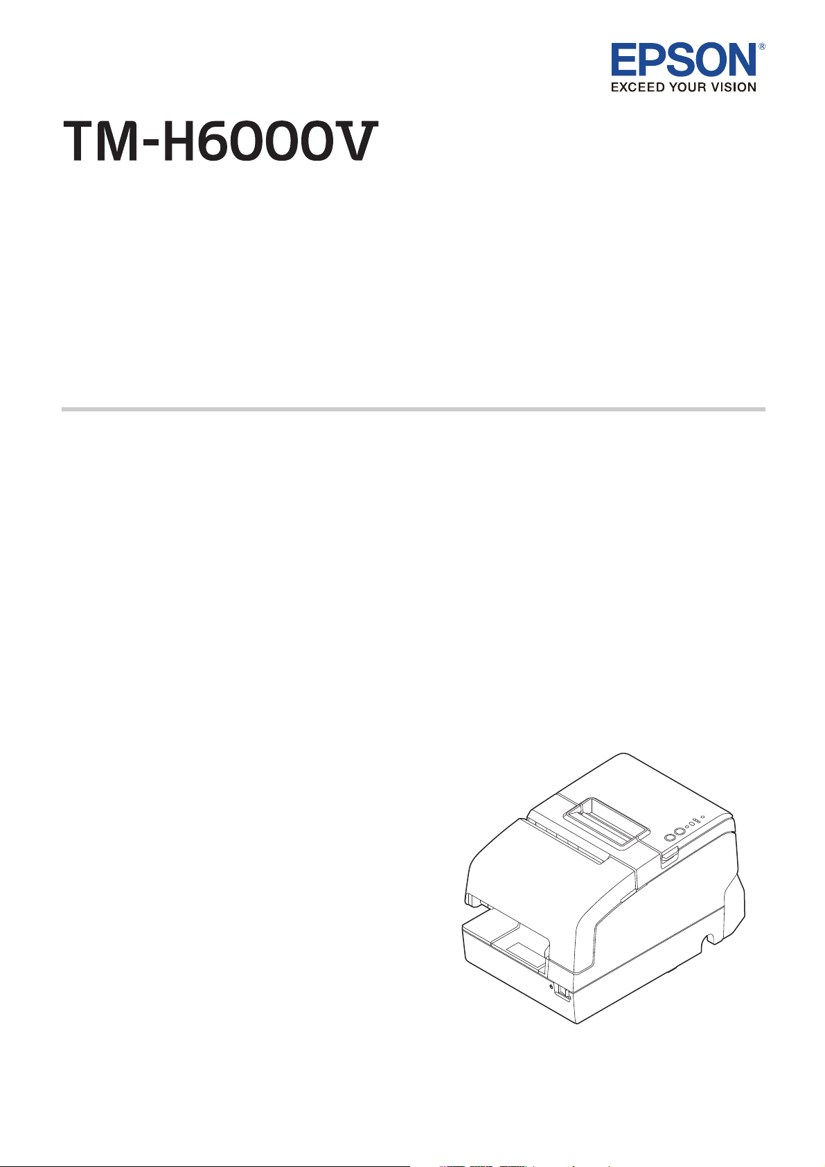
Part Names and Functions
1
2
3
4
5
6
7
1 NFC tag
A mark is printed here to indicate the position of the NFC tag. To establish communication with an
NFC device, bring the device close to this mark. For details on functions that use the NFC tag, refer to
the Technical Reference Guide.
2 Roll paper cover
Open this cover to install/replace the roll paper.
3 Receipt unit
Open this unit to install/replace the ribbon cartridge for endorsement printing.
4 Front cover
Open this cover to install/replace the ribbon cartridge for slip/validation printing.
5 Power switch
Use this switch to turn the printer on or off.
6 Manual cutter
Use this cutter when you cut the roll paper manually.
7 Connector cover
Use this cover to hide and protect rear connectors and cables.
4
Page 5
English
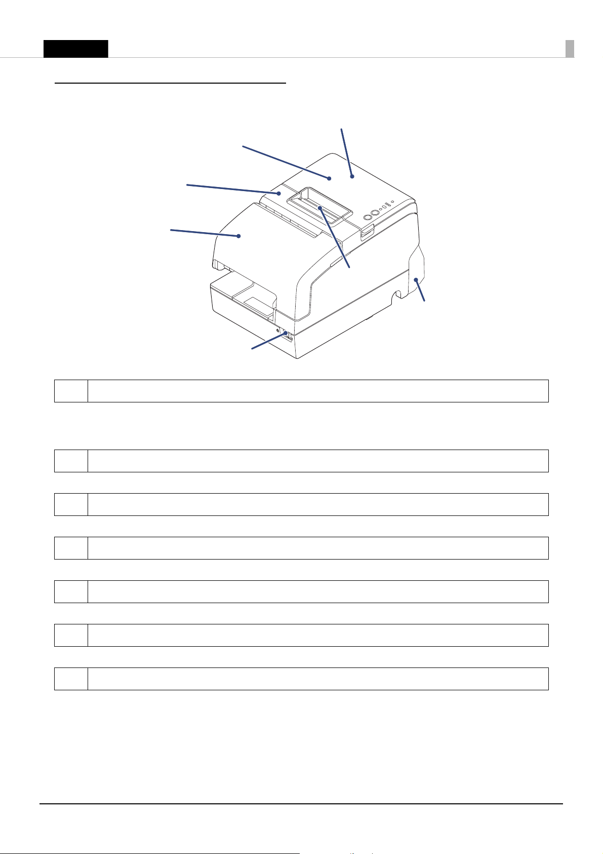
Control Panel
1
2
3
4
5
6
1 $ (Power) LED
On when the printer is on.
2 ! Error LED
The 3 LEDs indicate an error status. (
3 Paper LED
On when the roll paper is near its end.
4 Slip LED
On when the printer is in slip paper mode. Off when the printer is in roll paper mode. Flashes when
the printer is waiting for slip paper to be inserted/removed.
5 Feed button
This button feeds paper.
6 Release button
This button releases the retained paper.
U
"Error LEDs are on or flashing" on page 27)
5
Page 6
English
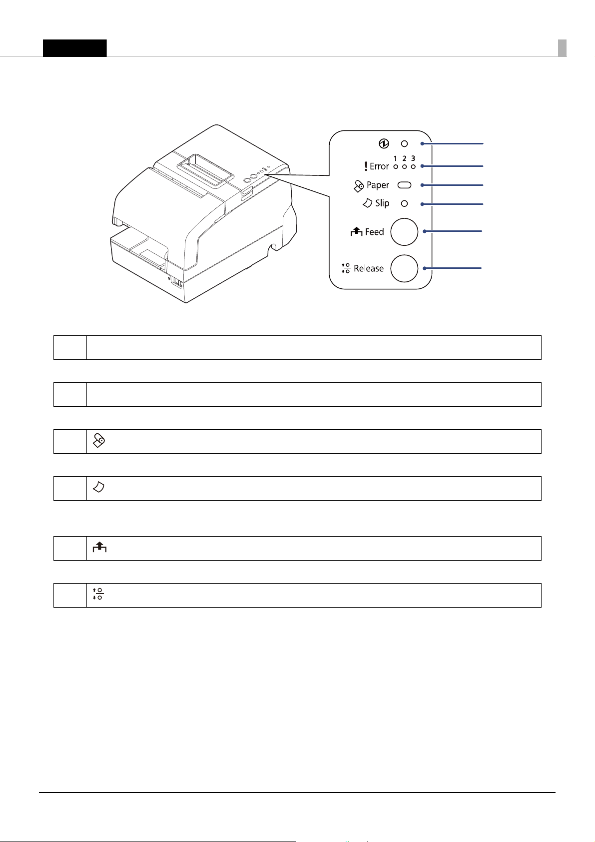
Connectors
1
2
34
5678
All connectors are located on the lower rear of the printer.
1 Serial interface connector
For connecting a serial cable for connecting to a computer.
2 USB Plus Power connector
For connecting a USB Plus Power cable for connecting to a computer.
3 DM-D connector
For connecting the customer display.
4 Drawer kick connector
For connecting a modular cable for the cash drawer.
5 USB connector
For connecting an Epson certified unit.
6 Ethernet connector
For connecting a LAN cable.
7 Power supply connector
For connecting the power cable.
8 USB connector (type-B)
For connecting a USB cable for connecting to a computer.
6
Page 7

English
Setup
To set up the printer, follow the steps below.
1. Removing the protective materials and tape (
2. Connecting the cables (
3. Attaching the connector cover (
4. Installing the ribbon cartridge (
5. Installing the roll paper (
6. Test printing (
7. Attaching the power switch cover (
8. Applying the LED information label (
U
U
"Connecting the Cables" on page 9)
U
"Attaching and Removing the Connector Cover" on page 11)
U
"Installing and Replacing the Ribbon Cartridge" on page 12)
U
"Installing the Roll Paper" on page 17)
"Test Printing" on page 19)
U
U
"Removing the Protective Materials and Tape" on page 8
"Attaching the Power Switch Cover" on page 19)
U
"Applying the LED Information Label" on page 20)
QNotes:
❏
When using the printer, be sure to install roll paper.
❏
For models with the MICR reader, do not place the printer near any magnetic fields to avoid decreasing the
MICR recognition rate. In particular, when you install the printer near a CRT display device, check the
recognition rate of the MICR reader.
)
7
Page 8
English
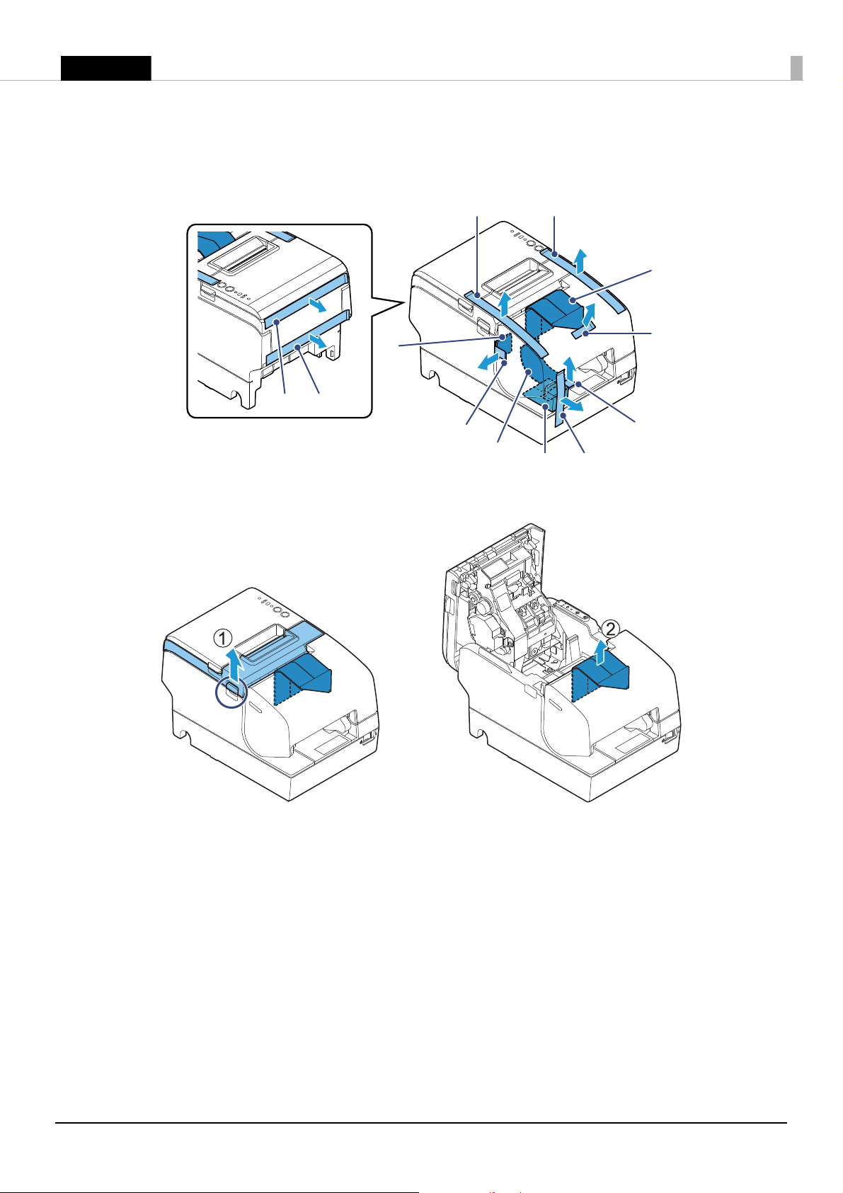
Removing the Protective Materials and Tape
A
B
C
D
E
F
G
H
I
J
K
L
Protective materials and tape are applied for protection against impacts during transportation. Remove all
of them, from A to L.
To remove protective material L, you must open the receipt unit.
8
Page 9
English
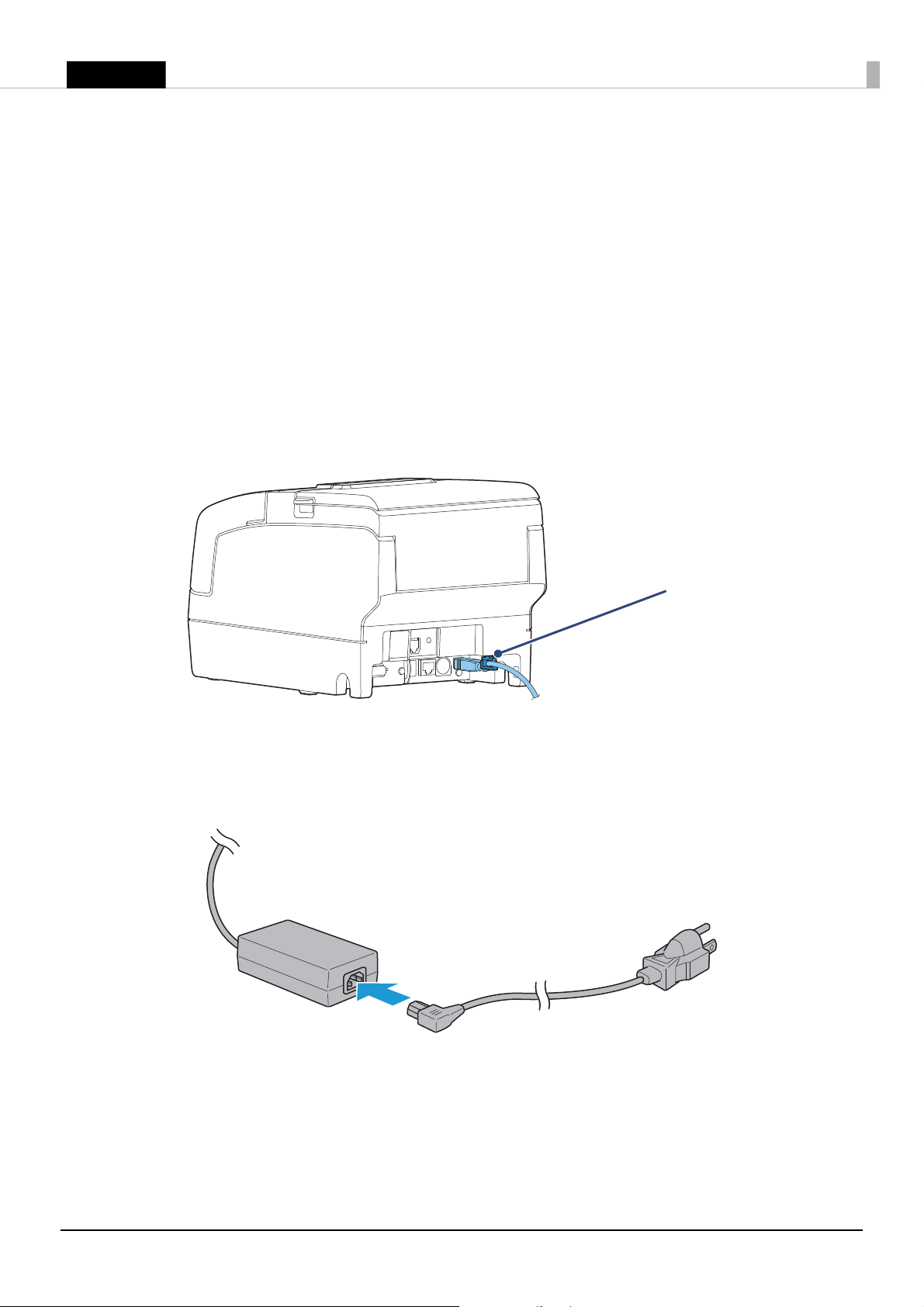
Connecting the Cables
Locking wire saddle
! CAUTION:
When using USB Plus Power interface, be careful of the following points. The printer may malfunction.
❏
Do not connect an AC adapter.
❏
Do not remove or insert the USB Plus Power cable while the printer is still on.
Q
Notes:
Available interfaces vary depending on the printer model.
1. Make sure the power switch is off.
2. Connect each interface cable to the printer. When using the USB interface, fix the USB cable with the
locking wire saddle to prevent the USB cable from coming off.
3. Connect the interface cable to the computer.
4. Connect the AC cable connector to the AC port of the AC adapter.
9
Page 10
English
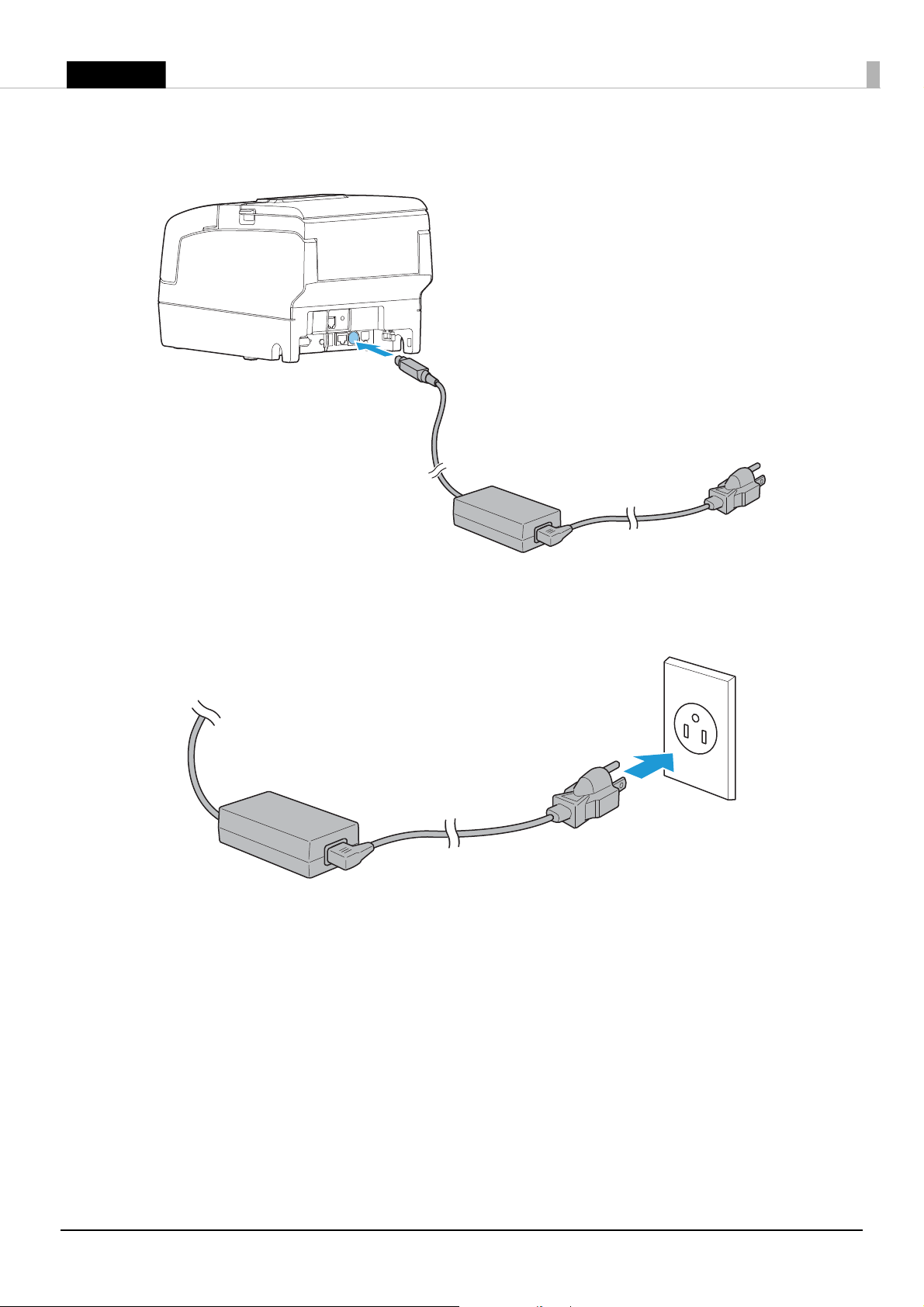
5. Connect the DC cable to the printer.
6. Insert the AC cable plug into a power outlet.
7. Set the AC adapter so that its label side is facing down.
10
Page 11

English
Attaching and Removing the Connector Cover
Follow the steps below to attach the connector cover to protect cables.
1. Align the 2 protrusions on the top of the connector cover with the holes in the back of the printer.
2. Push the connector cover forward so that the protrusions at the bottom of the printer fit properly in the
holes in both sides of the connector cover.
To remove the connector cover, push both sides of the cover inward to remove the holes in both sides of the
cover from the protrusions at the bottom of the printer.
11
Page 12

English
Installing and Replacing the Ribbon Cartridge
ON
Q
Notes:
Be sure to use the specified ribbon cassette. (U "Specifications" on page 31)
1. Turn the knob on the ribbon cartridge a little in the direction of the arrow marked on the cartridge to
remove any slack in the ribbon.
!CAUTION:
Make sure to note the direction of the arrow marked on the ribbon cartridge when turning the knob.
Turning it in the reverse direction may damage the cartridge.
2. Turn on the printer.
12
Page 13

English
3. Open the front cover.
4. Remove the used ribbon cartridge, if there is one.
5. Insert a new ribbon cartridge until it clicks into place.
6. Turn the knob on the cartridge in the marked direction again to remove any slack in the ribbon.
7. Close the front cover.
13
Page 14

English
Installing and Replacing the Ribbon Cartridge for Endorsement Printing
ON
If your printer is equipped with an endorsement printer, endorsement printing on slip paper is available.
Follow the steps below to install/replace the ribbon cartridge for the endorsement printer.
Q
Notes:
Be sure to use the specified ribbon cassette. (U "Specifications" on page 31)
1. Turn the knob on the ribbon cartridge a little in the direction of the arrow marked on the cartridge to
remove any slack in the ribbon.
!CAUTION:
Make sure to note the direction of the arrow marked on the ribbon cartridge when turning the knob.
Turning it in the reverse direction may damage the cartridge.
2. Turn on the printer.
14
Page 15

English
3. Open the receipt unit.
4. Remove the used ribbon cartridge, if there is one.
5. Insert a new ribbon cartridge until it clicks into place.
15
Page 16

English
6. Turn the knob on the cartridge in the marked direction again to remove any slack in the ribbon.
7. Close the receipt unit.
16
Page 17

English
Installing the Roll Paper
Q
Notes:
Be sure to use the specified paper. (U "Specifications" on page 31)
Follow the steps below to install the roll paper.
1. Make sure the printer is turned on.
2. Open the roll paper cover.
3. Insert the roll paper in the correct direction.
17
Page 18

English
4. Pull out some paper, and close the roll paper cover.
5. Tear off the paper with the manual cutter.
18
Page 19

English
Test Printing
After the printer setup or when the printer is not operating correctly, you can check the printer operation
with test printing. If the printer performs pattern printing following the steps below, the printer is operating
normally.
Test Printing on Roll Paper
Make sure all the covers are closed, and while pressing the Feed button, turn on the printer. After the
printer prints its status and the Paper LED flashes, press the Feed button again to restart the test printing.
Test Printing on Slip Paper
Make sure all the covers are closed, and while pressing the Release button, turn on the printer. After the Slip
LED flashes, insert the slip paper. If your printer is equipped with the endorsement printer, the printer
prints both sides of the paper.
Both types of test printing are completed when "*** completed ***" is printed.
Attaching the Power Switch Cover
By attaching the power switch cover, you can prevent accidental operations of the power switch.
You can turn on and off the power switch by inserting a pointed object in the holes on the power switch
cover. To detach the cover, use a pointed object.
To use this cover, install it as shown in the illustration below.
! WARNING:
If an accident occurs with the power switch cover attached, unplug the power cord immediately.
Continued use may cause a fire or electric shock.
19
Page 20

English
Applying the LED Information Label
You can use the LED information label to swiftly learn the status of the printer when an error occurs. Check
the printer's LED on/flashing pattern and identify the error type from the LED information label.
Or, you can scan the QR code using your smart device to check detailed information about the error and the
solution.
We recommend applying the LED information label on the reverse side of the front cover following the
steps below.
Q
Notes:
❏
Depending on your printer model, the LED information label may already be applied.
❏
There are 2 types of the LED information label; a label written in English and a label written in French.
Some models do not include the label written in French.
1. Open the front cover.
20
Page 21

English
2. Apply the LED Information Label in the position in the figure below.
21
Page 22

English
Handling Paper
!CAUTION:
❏
Be sure to use the specified paper. (U "Specifications" on page 31)
❏
Do not insert any paper that has clips or staples. This may cause paper jams and damage.
❏
Make sure the slip/validation paper is flat and without curls, folds, or wrinkles.
Installing and Replacing the Roll Paper
Follow the steps below to install/replace the roll paper.
1. Make sure the printer is turned on.
2. Open the roll paper cover.
3. Remove the used roll paper core, if there is one, and insert the roll paper in the correct direction.
22
Page 23

English
4. Pull out some paper, and close the roll paper cover.
5. Tear off the paper with the manual cutter.
23
Page 24

English
Inserting Slip Paper
!CAUTION:
Models with an MICR reader use a permanent magnet. Do not bring a magnetic card or the like near the
product.
When printing on slip paper, follow the steps below to insert the paper.
If your printer is equipped with a MICR reader, MICR reading is available by inserting the check paper so
that the MICR characters on the paper are on the right side.
1. Make sure the printer is turned on.
2. Set the paper so that the right edge of the paper contacts the paper guide on the right and insert the slip
paper. Refer to the label affixed to the printer.
Inserting Validation Paper
If your printer is a validation model, insert the paper in the same way as normal slip paper (See "Inserting Slip
Paper" on page 24
1. Make sure the printer is turned on.
2. Insert the paper with the right paper edge against the right side of the paper guide at the printer top, and
insert it as far as it will go.
3. Insert the paper straight down until the bottom edge of the paper touches the stopper.
) or follow the steps below.
24
Page 25

English
Cleaning the Product
a. Thermal head
b. Platen roller
ab
Cleaning the Printer Case
Be sure to turn off the printer, and wipe the dirt off the printer case with a dry cloth or a damp cloth.
!CAUTION:
Never clean the product with alcohol, benzine, thinner, or other such solvents. Doing so may damage or break
the parts made of plastic and rubber.
Cleaning the Thermal Head and the Platen Roller
Epson recommends cleaning the thermal head periodically (generally every 3 months) to maintain receipt
print quality.
Depending on the roll paper used, paper dust may stick to the platen roller and the paper may not be fed
correctly. To remove the paper dust, clean the platen roller with a cotton swab moistened with water. Turn
on the product power only after the water has completely dried.
!K CAUTION:
❏
The thermal head can be very hot after printing. Be careful not to touch it, and let it cool before you clean
it.
❏
Do not damage the thermal head by touching it with your fingers or any hard object.
1. Turn off the printer.
2. Open the roll paper cover.
3. Clean the thermal elements of the thermal head and platen roller with a cotton swab moistened with an
alcohol solvent (ethanol or IPA).
25
Page 26

English
Cleaning the MICR Head
If your printer is equipped with a MICR reader, when the MICR head becomes dirty, the printer cannot read
MICR characters normally.
Approximately every year, clean the MICR head with the following or an equivalent commercially available
cleaning sheet: KIC Products "Waffletechnology
MICR cleaning card".
!CAUTION:
❏
Be sure not to use an adhesive cleaning sheet.
❏
Be sure that the cleaning sheet is inserted with the correct side up and in the correct direction.
❏
Use a cleaning sheet only one time; then discard it.
1. Make sure the roll paper is installed correctly and the printer is turned off.
2. Open the roll paper cover.
3. While holding down the Release button, turn the power back on.
4. Press the Release button 7 times; then close the roll paper cover.
5. After the printer prints "*** RECOGNITION MODE *** Please set check." on the roll paper and the Slip
LED flashes, insert the cleaning sheet like standard slip paper.
6. Pull the ejected paper straight up out of the printer.
7. Turn off the printer to exit the cleaning mode.
26
Page 27

English
Troubleshooting
$ (Power) LED does not turn on
Check whether the power supply cable is correctly connected to the printer and the socket.
Error LEDs are on or flashing
Refer to the table below. For more detailed explanations or if the on/flashing pattern is not listed in this
table, scan the QR code on the LED information label (
or refer to the Technical Reference Guide.
O : On N : Off k : Flashing - : LED either on, off, or flashing
U
"Applying the LED Information Label" on page 20)
Power
OONN– – Either the roll paper cover,
OOON– – Autocutter does not work
OONO– – Slip paper or foreign material
OOOO– – The roll paper cover was
k ––– kkAn unrecoverable error
Error
123
Paper Slip Cause Solution and reference
❏ Make sure that the roll paper cover, receipt unit,
receipt unit, or front cover is
open, or there is no roll paper.
correctly.
may be jammed.
opened while the printer was
printing to roll paper, and
printing stopped.
occurred.
and front cover are closed.
"Part Names and Functions" on page 4
U
❏ Set roll paper.
U "Installing the Roll Paper" on page 17
Open the roll paper cover and check for any foreign
material. If the roll paper cover will not open, refer
"Roll paper cover will not open" on page 30.
to
Open the front cover and front carriage unit and
check for any foreign material.
"Slip paper is jammed" on page 29
U
Close the roll paper cover and perform error
recovery* from your system. While the printer is
operating independently (such as a test print, etc.),
restart the printer.
Turn off the power immediately when an
unrecoverable error occurs. If the same error occurs
again even after turning the power back on,
contact qualified service personnel.
*The method for error recovery varies depending on your system. Inquire with your system administrator.
27
Page 28

English
Roll paper is jammed
!K CAUTION:
Do not touch the thermal head, because it can be very hot after printing. Let it cool before you remove the
jammed paper.
1. Open the roll paper cover.
2. Remove the jammed paper.
28
Page 29

English
Slip paper is jammed
1. Open the front cover.
2. Open the front carriage unit using the lever on the right side of the front carriage unit.
3. Remove the jammed paper.
29
Page 30

English
Roll paper cover will not open
Knob
Pin
When the roll paper cover is locked and will not open, follow the steps below to return the autocutter blade
to the normal position to unlock the roll paper cover.
1. Open the receipt unit.
2. Use an object with a pointed tip such as a ballpoint pen or tweezers to turn the knob of the autocutter
blade in the direction of the arrow until you see a pin in the opening of the frame, as shown in
illustration below.
30
Page 31

English
Specifications
Printing method Receipt
Slip/Endorsement
Paper dimensions Receipt
Slip
Paper thickness
Inked ribbon Slip
*1
Interface
*2
Endorsement
Serial
Ethernet
USB
USB Plus Power
Wireless LAN
Supply voltage
*3
Current consumption
Te mp e ra tu r e
Humidity
Elevation
Overall dimensions
Weight (mass)
Mbps: megabits per second
*1: Factory installed options
*2: The available interfaces vary depending on the printer model.
*3: Be sure to use a safety-standards-applied power source that meets the following specifications.
Rated output: 2.1 - 10.0 A, Maximum output: 240 VA or less
Thermal line
*1
9-pin serial impact dot matrix
79.5 ± 0.5 × 83 mm {3.1 ± 0.02 × 3.3"}
68 to 230 × 68 to 297 mm {2.68 to 9.06 × 2.68 to 11.7"} (W × L)
Minimum size: 68 × 152 mm {2.68 × 5.98"}
Slip (single ply): 0.09 to 0.22 mm {0.0035 to 0.0087"}
ERC-32
ERC-43
RS-232
10BASE-T/100BASE-TX
USB 2.0, Full-speed (12 Mbps)
Full-speed (12 Mbps)
Connect the Epson certified unit to the USB connector.
DC + 24 V ± 7%
Mean: Approximately 1.8 A
Operating: 5 to 45°C {41 to 113°F}
Storage: –10 to 50°C {14 to 122°F}, except for paper
Operating: 10 to 90% RH
Storage: 10 to 90% RH, except for paper
3,000 m or less
181 × 186 × 278 mm {7.13 × 7.32 × 10.94"} (H × W × D)
Approx. 4.4 kg {9.7 lb}
31
Page 32

English
Appendix
Downloading Drivers, Utilities, and Manuals
Printer drivers, utilities, and manuals can be downloaded from one of the following URLs.
For customers in North America, go to the following web site:
http://www.epson.com/support/
For customers in other countries, go to the following web site:
http://download.epson-biz.com/?service=pos
Restriction of Use
When this product is used for applications requiring high reliability/safety, such as transportation devices
related to aviation, rail, marine, automotive, etc.; disaster prevention devices; various safety devices, etc.; or
functional/precision devices, etc.; you should use this product only after giving consideration to including
fail-safes and redundancies into your design to maintain safety and total system reliability. Because this
product was not intended for use in applications requiring extremely high reliability/safety, such as
aerospace equipment, main communication equipment, nuclear power control equipment, or medical
equipment related to direct medical care, etc., please make your own judgment on this product’s suitability
after a full evaluation.
Notes
(1) All rights reserved. No part of this publication may be reproduced, stored in a retrieval system, or
transmitted in any form or by any means, electronic, mechanical, photocopying, recording, or otherwise,
without the prior written permission of Seiko Epson Corporation.
(2) No patent liability is assumed with respect to the use of the information contained herein.
(3) While every precaution has been taken in the preparation of this book, Seiko Epson Corporation
assumes no responsibility for errors or omissions.
(4) Neither is any liability assumed for damages resulting from the use of the information contained herein.
(5) Neither Seiko Epson Corporation nor its affiliates shall be liable to the purchaser of this product or third
parties for damages, losses, costs, or expenses incurred by purchaser or third parties as a result of:
accident, misuse, or abuse of this product or unauthorized modifications, repairs, or alterations to this
product, or (excluding the U.S.) failure to strictly comply with Seiko Epson Corporation’s operating and
maintenance instructions.
(6) Seiko Epson Corporation shall not be liable against any damages or problems arising from the use of any
options or any consumable products other than those designated as Original Epson Products or Epson
Approved Products by Seiko Epson Corporation.
Trademarks
EPSON is a registered trademark of Seiko Epson Corporation.
Exceed Your Vision is a registered trademark or trademark of Seiko Epson Corporation.
All other trademarks are the property of their respective owners and used for identification purpose only.
The contents of this manual are subject to change without notice.
©Seiko Epson Corporation 2018. All rights reserved.
32
 Loading...