

Technical Reference Guide
Describes features of the product.
Describes setup and installation of the product and
peripherals.
Describes advanced usage methods for the product.
Describes how to control the printer and necessary
information when you develop applications.
Describes how to handle the product.
Describes actions to take when a trouble occurs.
Describes precautions for replacement.
Describes general specications and character code tables.
Product Overview
Setup
Advanced Usage
Application Development Information
Handling
Troubleshooting
Replacement of the TM-H6000IV
Appendix
M00111104
Rev. E

Cautions
• No part of this document may be reproduced, stored in a retrieval system, or transmitted in any form or by
any means, electronic, mechanical, photocopying, recording, or otherwise, without the prior written
permission of Seiko Epson Corporation.
• The contents of this document are subject to change without notice. Please contact us for the latest
information.
• While every precaution has been taken in the preparation of this document, Seiko Epson Corporation
assumes no responsibility for errors or omissions.
• Neither is any liability assumed for damages resulting from the use of the information contained herein.
• Neither Seiko Epson Corporation nor its affiliates shall be liable to the purchaser of this product or third
parties for damages, losses, costs, or expenses incurred by the purchaser or third parties as a result of:
accident, misuse, or abuse of this product or unauthorized modifications, repairs, or alterations to this
product, or (excluding the U.S.) failure to strictly comply with Seiko Epson Corporation’s operating and
maintenance instructions.
• Seiko Epson Corporation shall not be liable against any damages or problems arising from the use of any
options or any consumable products other than those designated as Original Epson Products or Epson
Approved Products by Seiko Epson Corporation.
Trademarks
EPSON is a registered trademark of Seiko Epson Corporation.
Exceed Your Vision and ESC/POS are registered trademarks or trademarks of Seiko Epson Corporation.
Microsoft, Windows, and Windows Vista are registered trademarks of Microsoft Corporation in the United
States and/or other countries.
Wi-Fi
®, WPA™, and WPA2™ are either registered trademarks or trademarks of Wi-Fi Alliance®.
The Bluetooth
such marks by Seiko Epson Corporation is under license.
IOS is a trademark or registered trademark of Cisco in the U.S. and other countries and is used under license.
Apple, Apple TV, Apple Watch, iPad, iPad Air, iPad Pro, iPhone, and Lightning are trademarks of Apple Inc.,
registered in the U.S. and other countries. tvOS is a trademark of Apple Inc.
iBeacon is a trademark of Apple Inc.
Android
Google Play and the Google Playlogo are trademarks of Google LLC.
All other trademarks are the property of their respective owners and used for identification purpose only.
® word mark and logos are registered trademarks owned by Bluetooth SIG, Inc. and any use of
™ is a trademark of Google LLC.
ESC/POS® Command System
Epson ESC/POS is a proprietary POS printer command system that includes patented or patent-pending
commands. ESC/POS is compatible with most Epson POS printers and displays.
ESC/POS is designed to reduce the processing load on the host computer in POS environments. It comprises a
set of highly functional and efficient commands and also offers the flexibility to easily make future upgrades.
©Seiko Epson Corporation 2018-2021.
2
For Safety
Key to Symbols
The symbols in this manual are identified by their level of importance, as defined below. Read the following
carefully before handling the product.
You must follow warnings carefully to avoid serious bodily injury.
WARNING
Provides information that must be observed to prevent damage to the equipment or loss of data.
• Possibility of sustaining physical injuries.
CAUTION
• Possibility of causing physical damage.
• Possibility of causing information loss.
Provides information that must be observed to avoid damage to your equipment or a malfunction.
Provides important information and useful tips.
Warnings
WARNING
• Shut down your equipment immediately if it produces smoke, a strange odor, or unusual noise.
Continued use may lead to fire. Immediately unplug the equipment and contact qualified service personnel for advice.
• Never attempt to repair this product yourself. Improper repair work can be dangerous.
• Never disassemble or modify this product. Tampering with this product may result in injury or
fire.
• Do not use this product with any voltage other than the specified one. Doing so may lead to fire
or electric shock.
• For the power cable, use either the included one or a designated one that meets the relevant
safety standards of the area where you plan to use it.
• Do not allow foreign matter to fall into the equipment. Penetration by foreign objects may lead
to fire.
• If water or other liquid spills into this equipment, unplug the AC cable immediately, and contact
qualified service personnel for advice. Continued usage may lead to fire.
• Do not use aerosol sprayers containing flammable gas inside or around this product. Doing so
may cause fire.
3
Cautions
• Do not connect cables in ways other than those mentioned in this manual. Different connec-
CAUTION
• Be sure to set this equipment on a firm, stable, horizontal surface. Product may break or cause
• Do not use in locations subject to high humidity or dust levels. Excessive humidity and dust may
• Do not place heavy objects on top of this product. Never stand or lean on this product. Equip-
• Take care not to injure your fingers on the manual cutter
• To ensure safety, unplug this product before leaving it unused for an extended period.
• Do not connect a telephone line to the drawer kick connector or the display module connector;
• Do not put your hand inside this product or touch the white flat cable during printing.
• Make sure cords and foreign objects are not caught in the printer.
• Do not open the covers during printing or autocutting.
• To prevent a paper jam, do not prevent paper from being ejected from the paper exit, and do
Caution Labels
tions may cause equipment damage and burning.
injury if it falls.
cause equipment damage or fire.
ment may fall or collapse, causing breakage and possible injury.
• When you remove printed paper
• When you perform other operations, such as loading/replacing roll paper
otherwise the printer and the telephone line may be damaged.
not pull the paper being ejected.
The caution labels on the product indicate the following precautions.
CAUTION:
Do not touch the thermal head because it can be very hot after printing.
CAUTION:
Do not touch the cables in the product. Doing so can cause product malfunctions.
4

Restriction of Use
When this product is used for applications requiring high reliability/safety, such as transportation devices
related to aviation, rail, marine, automotive, etc.; disaster prevention devices; various safety devices, etc.; or
functional/precision devices, etc., you should use this product only after giving consideration to including failsafes and redundancies into your design to maintain safety and total system reliability. Because this product was
not intended for use in applications requiring extremely high reliability/safety, such as aerospace equipment,
main communication equipment, nuclear power control equipment, or medical equipment related to direct
medical care, etc., please make your own judgment on this product's suitability after a full evaluation.
Note about interference
•
This product generates, uses, and can radiate radio frequency energy and, if not installed and used in
accordance with the instruction manual, may cause harmful interference to radio communications.
•
If this equipment does cause harmful interference to radio or television reception, which can be determined by
turning the equipment off and on, the user is encouraged to try to correct the interference by one or more of the
following measures:
- Reorient or relocate the receiving antenna for the radio/TV.
- Increase the separation between the equipment and the radio/TV.
- Connect the equipment into an outlet on a circuit different from that to which the receiver is connected.
- Consult your dealer or an experienced radio/TV technician for help.
•
Never disassemble or modify this product.
•
Seiko Epson Corporation shall not be liable for interference to radio/TV resulting from changes or
modifications to this product not expressly approved by Seiko Epson Corporation.
Open Source Software License
This product uses open source software in addition to Epson proprietary software.
For information of the open source software used in this product, see the following URL.
https://xxx.xxx.xxx.xxx/licenses.html
For "xxx.xxx.xxx.xxx" in the above URL, input your printer’s IP address.
5

About this Manual
Aim of the Manual
This manual provides developers/engineers with all the necessary information for design, development and
installation of a POS system, and also design and development of a printer application.
Manual Content
The manual is made up of the following sections:
Chapter 1
Chapter 2
Chapter 3
Chapter 4
Chapter 5
Chapter 6
Chapter 7
Appendix
Product Overview
Setup
Advanced Usage
Application Development Information
Handling
Troubleshooting
Replacement of the TM-H6000IV
Product Specifications
Character Code Tables
6

Contents
■ For Safety..................................................................................................................................3
Key to Symbols.................................................................................................................................................................... 3
Warnings ............................................................................................................................................................................... 3
Cautions................................................................................................................................................................................. 4
■ Caution Labels .........................................................................................................................4
■ Restriction of Use ....................................................................................................................5
■ Note about interference ........................................................................................................5
■ Open Source Software License.............................................................................................5
■ About this Manual ..................................................................................................................6
Aim of the Manual ............................................................................................................................................................. 6
Manual Content .................................................................................................................................................................. 6
■ Contents....................................................................................................................................7
Product Overview ..........................................................................................13
■ Features ................................................................................................................................. 13
■ Product Configurations ...................................................................................................... 15
Models..................................................................................................................................................................................15
Case color............................................................................................................................................................................15
Accessories .........................................................................................................................................................................15
■ Part Names and Functions ................................................................................................. 16
Control Panel .....................................................................................................................................................................17
Connectors .........................................................................................................................................................................18
Online and Offline............................................................................................................................................................19
LED on/flashing patterns...............................................................................................................................................20
■ NV Memory ........................................................................................................................... 22
NV Graphics Memory......................................................................................................................................................22
User NV Memory ..............................................................................................................................................................22
Memory Switches.............................................................................................................................................................22
R/E (Receipt Enhancement) ..........................................................................................................................................22
Maintenance Counter.....................................................................................................................................................23
■ Simple Setup for Wireless LAN .......................................................................................... 24
■ Useful Functions for Smart Devices.................................................................................. 25
NFC Tag................................................................................................................................................................................25
QR Code...............................................................................................................................................................................25
■ Printing Using Multiple Interfaces.................................................................................... 26
7

Setup ...............................................................................................................27
■ Flow of Setup ........................................................................................................................ 27
■ Removing the Protective Materials and Tape................................................................. 29
■ Connecting the AC adapter................................................................................................ 30
Connecting the AC adapter..........................................................................................................................................30
■ Connecting the Printer to the Host................................................................................... 32
USB Interface .....................................................................................................................................................................32
Ethernet Interface ............................................................................................................................................................32
Wireless LAN Interface....................................................................................................................................................34
Bluetooth Interface..........................................................................................................................................................38
Serial Interface ..................................................................................................................................................................42
USB Plus Power Interface ..............................................................................................................................................42
■ Connecting the Cash Drawer............................................................................................. 43
Required specifications of cash drawer ...................................................................................................................43
Connecting the drawer kick cable .............................................................................................................................44
■ Installing the Customer Display ........................................................................................ 45
■ Attaching the Connector Cover......................................................................................... 46
■ Installing and Replacing the Ribbon Cartridge.............................................................. 47
■ Installing and Replacing the Ribbon Cartridge for Endorsement Printing............... 49
■ Installing the Roll Paper...................................................................................................... 52
■ Test Printing .......................................................................................................................... 54
■ Attaching the Power Switch Cover ................................................................................... 55
■ Applying the LED Information Label................................................................................ 56
■ RTC Settings .......................................................................................................................... 58
■ Adjusting the Paper Roll Near-End Sensor...................................................................... 59
■ Changing the Paper Width ................................................................................................. 60
Advanced Usage ............................................................................................61
■ Setting the DIP Switches..................................................................................................... 61
Setting Procedure ............................................................................................................................................................61
When a Serial Interface is Connected .......................................................................................................................62
When Another Interface is Connected .....................................................................................................................63
Selecting the Print Density (DIP Switches 2-3/2-4) ..............................................................................................64
Selecting the BUSY Status.............................................................................................................................................64
■ Software Settings................................................................................................................. 65
Functions.............................................................................................................................................................................67
Setting and reference items shared by Ethernet/Wi-Fi ......................................................................................73
Setting and reference items for Ethernet ................................................................................................................74
Setting and reference items for Wi-Fi........................................................................................................................75
Setting and reference items for Bluetooth .............................................................................................................76
8

■ Setting/Checking Modes .................................................................................................... 77
Self-test Mode ...................................................................................................................................................................79
NV Graphics Information Print Mode........................................................................................................................80
Receipt Enhancement Information Print Mode ....................................................................................................81
Software Setting Mode ..................................................................................................................................................82
Restore Default Values Mode.......................................................................................................................................84
Interface Setup Mode.....................................................................................................................................................86
TM-Intelligent Settings Information Print Mode ..................................................................................................88
Peripheral Device Information Print Mode.............................................................................................................88
Hexadecimal Dumping Mode .....................................................................................................................................89
■ Printing a Status Sheet........................................................................................................ 90
■ Resetting the Interface Settings ....................................................................................... 93
■ TM-Intelligent Function...................................................................................................... 94
Server direct print ............................................................................................................................................................94
Application Development Information.......................................................95
■ Controlling the Printer ........................................................................................................ 95
ePOS-Print XML.................................................................................................................................................................95
ePOS-Device XML.............................................................................................................................................................95
ESC/POS...............................................................................................................................................................................95
■ Controlling the Cash Drawer.............................................................................................. 96
■ Software................................................................................................................................. 97
Development Kits ............................................................................................................................................................97
Drivers ..................................................................................................................................................................................98
Utilities .................................................................................................................................................................................98
Others...................................................................................................................................................................................99
Download ...........................................................................................................................................................................99
■ Application Development and Distribution for iOS.................................................... 100
■ Notes on Printing Barcodes and Two-dimensional Symbols..................................... 101
Handling ...................................................................................................... 102
■ Installing and Replacing Roll Paper................................................................................ 102
■ Installing Slip Paper........................................................................................................... 104
■ Inserting Validation Paper................................................................................................ 105
■ Cleaning the Product......................................................................................................... 106
Cleaning the Printer Case ...........................................................................................................................................106
Cleaning the Thermal Head and the Platen Roller............................................................................................ 106
Cleaning the MICR Head............................................................................................................................................. 107
■ Preparing for Transport..................................................................................................... 108
9

Troubleshooting.......................................................................................... 109
■ LED on/flashing patterns.................................................................................................. 110
LED on/flashing patterns............................................................................................................................................ 110
Printer operating status .............................................................................................................................................. 111
Errors that recover automatically ............................................................................................................................ 112
Recoverable errors ........................................................................................................................................................112
Unrecoverable errors ................................................................................................................................................... 113
■ Print Quality Problem........................................................................................................ 114
Print Quality Problem (Receipt printer)................................................................................................................. 114
Print Quality Problem (Slip/ Validation/ Endorsement printer).................................................................... 114
■ Setting slip paper does not start printing..................................................................... 116
Slip LED is flashing continuously............................................................................................................................. 116
Slip LED is flashing 3 times ........................................................................................................................................ 116
Slip LED is off................................................................................................................................................................... 116
Slip LED does not change from flashing to lit up .............................................................................................. 116
■ Even when slip paper is set, paper is fed and an error occurs................................... 117
■ Slip LED does not turn off even though slip paper is removed................................. 117
■ MICR cannot be read ......................................................................................................... 117
■ The customer display does not appear.......................................................................... 118
Does not appear on the customer display........................................................................................................... 118
Text is garbled ................................................................................................................................................................ 118
■ The cash drawer does not open ...................................................................................... 118
■ Auto cutter error ................................................................................................................ 119
■ Paper jam............................................................................................................................. 122
Roll paper is jammed ................................................................................................................................................... 122
Slip paper is jammed ................................................................................................................................................... 123
■ Roll paper cover will not open......................................................................................... 126
Printing stop by cover open...................................................................................................................................... 127
■ Printing from the computer is disabled/Printing was suddenly stopped............... 128
Printer is offline .............................................................................................................................................................. 128
Reconnect the printer and the computer ............................................................................................................ 128
LAN setting...................................................................................................................................................................... 128
Check installation of printer driver ......................................................................................................................... 128
■ Power does not turn on .................................................................................................... 129
Replacement of the TM-H6000IV .............................................................. 130
■ Compatibility ...................................................................................................................... 131
Printing ............................................................................................................................................................................. 131
Print Density.................................................................................................................................................................... 131
10

Printable Area................................................................................................................................................................. 131
Cutting Method ............................................................................................................................................................. 131
Receive Buffer................................................................................................................................................................. 131
Memory Capacity.......................................................................................................................................................... 132
Electrical Characteristics............................................................................................................................................. 132
DIP Switches.................................................................................................................................................................... 132
Printer Status .................................................................................................................................................................. 132
Logo Registration.......................................................................................................................................................... 132
Driver Compatibility ..................................................................................................................................................... 132
USB Low Power Consumption Mode ..................................................................................................................... 132
Maintenance Counter.................................................................................................................................................. 132
Overall Dimensions ...................................................................................................................................................... 133
■ Additional Functions and Functional Improvements................................................. 134
Print Speed ...................................................................................................................................................................... 134
Interface............................................................................................................................................................................ 134
SimpleAP Function ....................................................................................................................................................... 134
NFC ..................................................................................................................................................................................... 134
Epson TM Utility for iOS/Android ............................................................................................................................ 134
Software Settings .......................................................................................................................................................... 135
TM-Intelligent function............................................................................................................................................... 135
Appendix...................................................................................................... 136
■ Product Specifications ...................................................................................................... 136
Printing Specifications................................................................................................................................................. 138
Character Specifications ............................................................................................................................................. 140
Paper Specifications ..................................................................................................................................................... 141
Printable Area................................................................................................................................................................. 144
Printing and Cutting Positions ................................................................................................................................. 146
Ribbon Cassette.............................................................................................................................................................146
Notes on using the endorsement printer............................................................................................................. 147
MICR Reader (Factory-Installed Option) ............................................................................................................... 147
Barcode/ Two-dimensional symbol/composite symbol ................................................................................. 150
Notes on using the multi-tone graphics printing.............................................................................................. 151
Electrical Characteristics............................................................................................................................................. 152
Reliability.......................................................................................................................................................................... 153
Environmental Conditions ......................................................................................................................................... 154
External Dimensions and Mass ................................................................................................................................ 155
■ Specifications of Interfaces and Connectors ................................................................ 156
USB Interface .................................................................................................................................................................. 156
Network Interface ......................................................................................................................................................... 157
Bluetooth Interface....................................................................................................................................................... 159
RS-232 Serial Interface................................................................................................................................................. 162
NFC Tag............................................................................................................................................................................. 165
11

■ Bluetooth Low Energy Technology Advertising........................................................... 166
Introduction .................................................................................................................................................................... 166
Dongle specifications .................................................................................................................................................. 166
Procedure......................................................................................................................................................................... 166
Changing the Bluetooth Low Energy Technology Advertising Packet...................................................... 167
■ Character Code Tables....................................................................................................... 179
12

Product Overview
This chapter describes features and specifications of the product.
Features
Slip printing
• High throughput using bidirectional minimum distance printing.
Chapter 1 Product Overview
• MICR reading function (option)
• Eight-line validation printing function (option)
• Check endorsement printing function (option)
• Check MICR reading, endorsement printing, and slip printing are performed continuously in that order.
Receipt printing
• High speed printing (350 mm/s maximum).
• Multi-tone graphic printing.
• Bar code and two-dimensional symbol printing.
• Shifting from 80 mm width paper printing to 58 mm width paper printing is available.
• Equipped with an autocutter.
• Paper saving function.
Handling
• Easy drop-in paper loading
Software
1
•
TM-Intelligent function is supported.
• Supports Server Direct Print that sends a request for print data from the product to the Web server at
regular intervals.
• ESC/POS Command System.
• OPOS ADK, OPOS ADK for .NET, JavaPOS ADK, and Windows printer drivers.
• Printing from a tablet (Epson ePOS SDK)
• Bar code and two-dimensional symbol printing.
13

Interface
• Equipped with USB and Ethernet by default.
• Either serial, Bluetooth, or USB Plus Power can be built-in by factory option.
• Optional Wireless LAN cable set is available.
Functions
• NFC tag built into the printer unit for printing to a touched printer.
• Supports printing using multiple interfaces.
• Enables HTTPS communication.
• A maintenance counter function is supported.
• Connect the Laird Connectivity BT-820 to support iBeacon.
Others
• Small footprint and simple design.
Chapter 1 Product Overview
1
• Direct connection of Epson customer display series (DM-D) is possible.
14

Chapter 1 Product Overview
Product Configurations
Models
Model name MICR Endorsement printer Validation
Basic model - - -
MICR model ✔ --
Endorsement/MICR model ✔✔ -
Validation model - - ✔
Validation/MICR model ✔ - ✔
Case color
1
• Black (EBCK)
• White (ENN8.5)
Accessories
Included
• AC adapter *
• AC cable *
• Roll paper
• Power switch cover
• Connector cover
• Manuals
• LED information label *
• Ink ribbon cartridge ERC-32(B)
• Ink ribbon cartridge ERC-43(B) *
* May not be included depending on the model.
Options
• PG-58II: 58 mm width paper guide.
• TA-6000II: Printer attachment.
• OT-DC6000: Cover for protecting the wireless LAN unit.
• OT-WL02, OT-WL05, OT-WL06: Wireless LAN cable set.
• DM-D110, DM-D210: Customer display.
• DP-502: Dedicated stand for customer display.
15
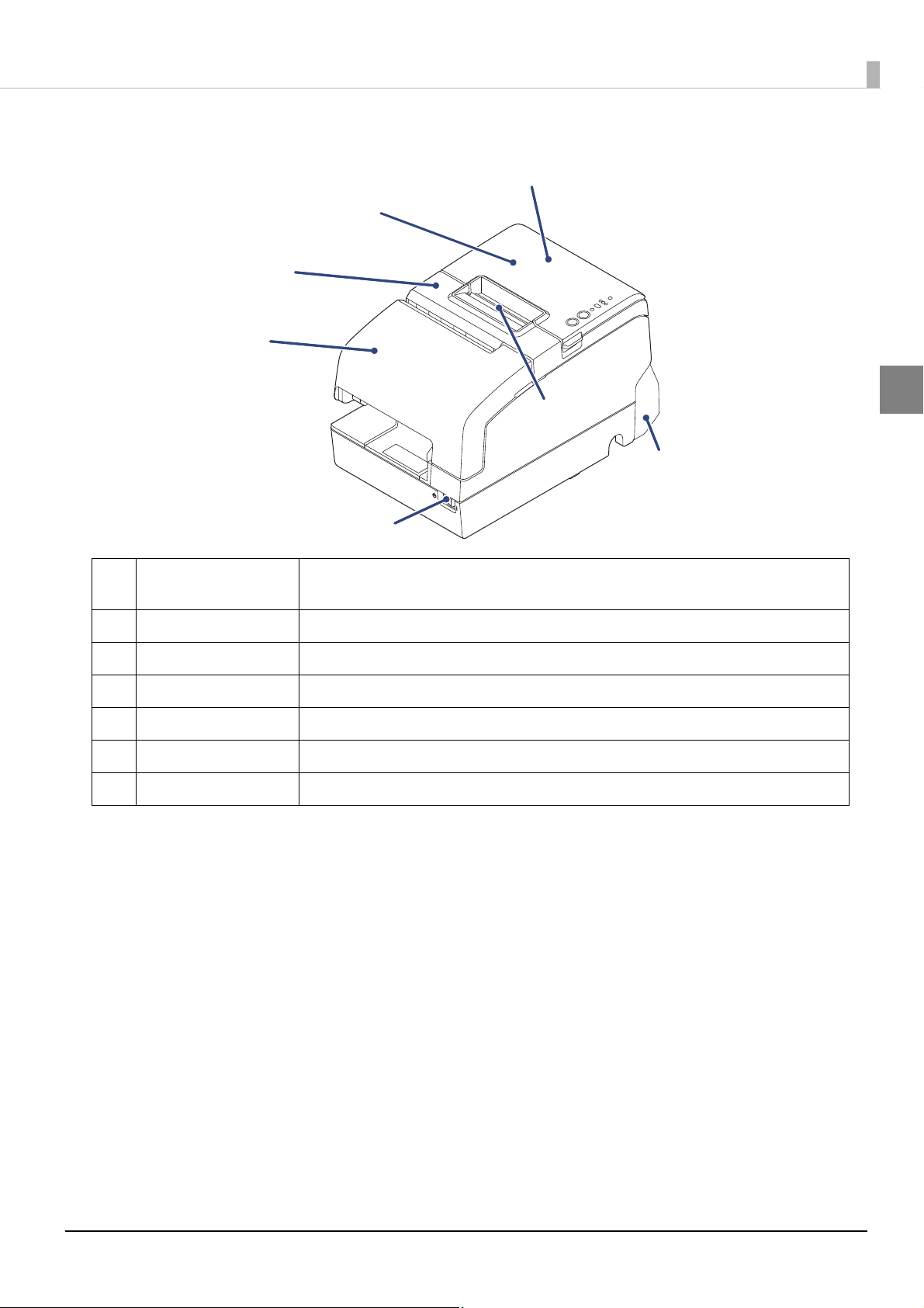
Part Names and Functions
1
2
3
4
5
6
7
Chapter 1 Product Overview
1
1 NFC Tag A mark is printed here to indicate the position of the NFC tag. To establish communication
with an NFC device, bring the device close to this mark.
2 Roll paper cover Open this cover to install/replace the roll paper.
3 Receipt unit Open this cover to install/replace the ribbon cartridge for endorsement printing.
4 Front cover Open this cover to install/replace the ribbon cartridge for slip/validation printing.
5 Power switch Use this switch to turn on or off the printer.
6 Manual cutter Use this cutter when you cut the roll paper manually.
7 Connector cover Use this cover to hide and protect rear connectors and cables.
16
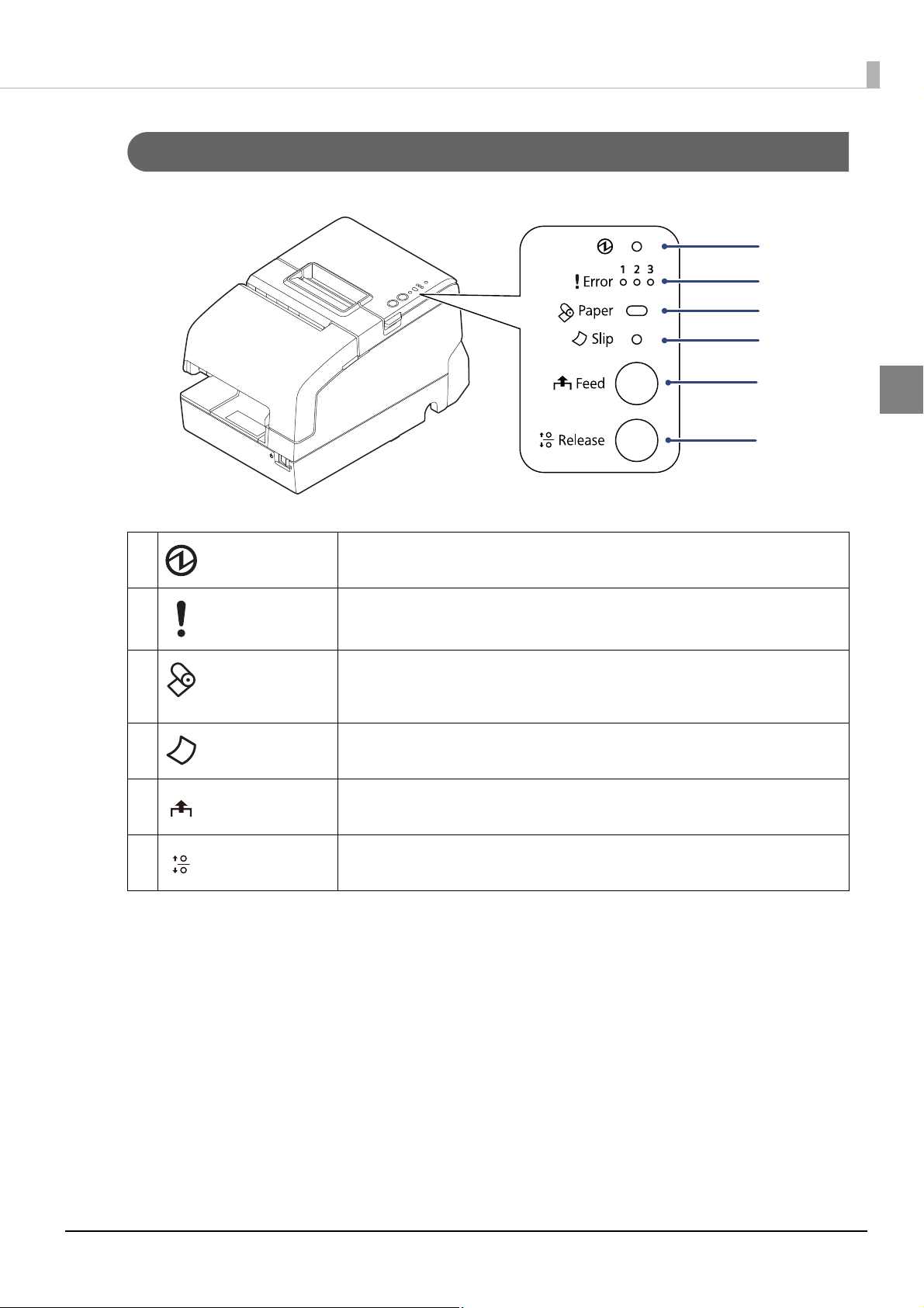
Control Panel
1
2
3
4
5
6
Chapter 1 Product Overview
1
1
2 Error LED The 3 LEDs indicate an error status.
3 Paper LED Flashes when waiting for test printing on the roll paper.
4 Slip LED On when the printer is in slip paper mode. Off when the printer is in roll paper mode.
5 Feed button This button feeds paper.
6 Release button This button releases the retained paper.
(Power) LED
On when the printer is on.
(See "LED on/flashing patterns" on page 20.)
Flashes to instruct you to press the Feed button and when there is a paper near-end.
On when there is no paper.
Flashes when the printer is waiting for slip paper to be inserted/removed.
17
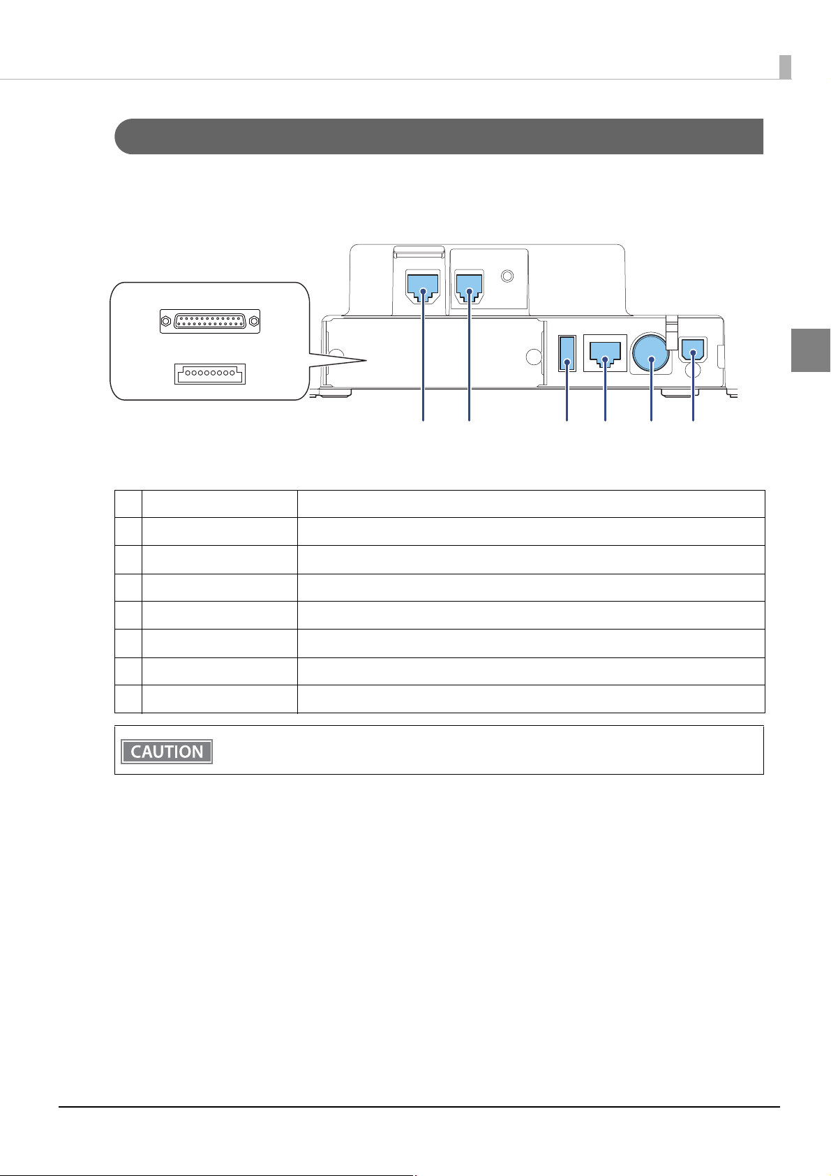
Connectors
1
2
34 5678
All connectors are located on the lower rear of the printer.
Chapter 1 Product Overview
1
1 Serial Interface connector Connects the serial cable for connecting to a computer.
2 USB Plus Power connector Connects the USB Plus Power cable for connecting to a computer.
3 DM-D connector Connects the customer display.
4 Drawer kick connector Connects the cash drawer.
5 USB connector Connects the Epson certified unit.
6 Ethernet connector Connects the 10BASE-T/100BASE-TX ethernet cable
7 Power supply connector Connect the AC adapter.
8 USB connector (type-B) Connects the USB cable for connecting to a computer.
Do not insert a Type-B USB connector into the Ethernet connector, the drawer kick connector, or the
DM-D connector. If it is inserted, the connector, printer, and the system may malfunction.
18

Online and Offline
Online
When the product is ready for normal printing, it is "online".
Offline
The printer automatically goes offline under the following conditions:
• While the printer power is turning on/off
Chapter 1 Product Overview
• While a self-test is running
• While the roll paper cover, the front cover or the receipt unit is open
• While roll paper is fed using the Feed button
• When the printer stops printing due to a paper-end
(if an empty paper supply is detected by the roll paper end sensor or if the driver has been set to stop printing
when a roll paper near end is detected)
• During a macro execution standby state
• When an error has occurred
1
19
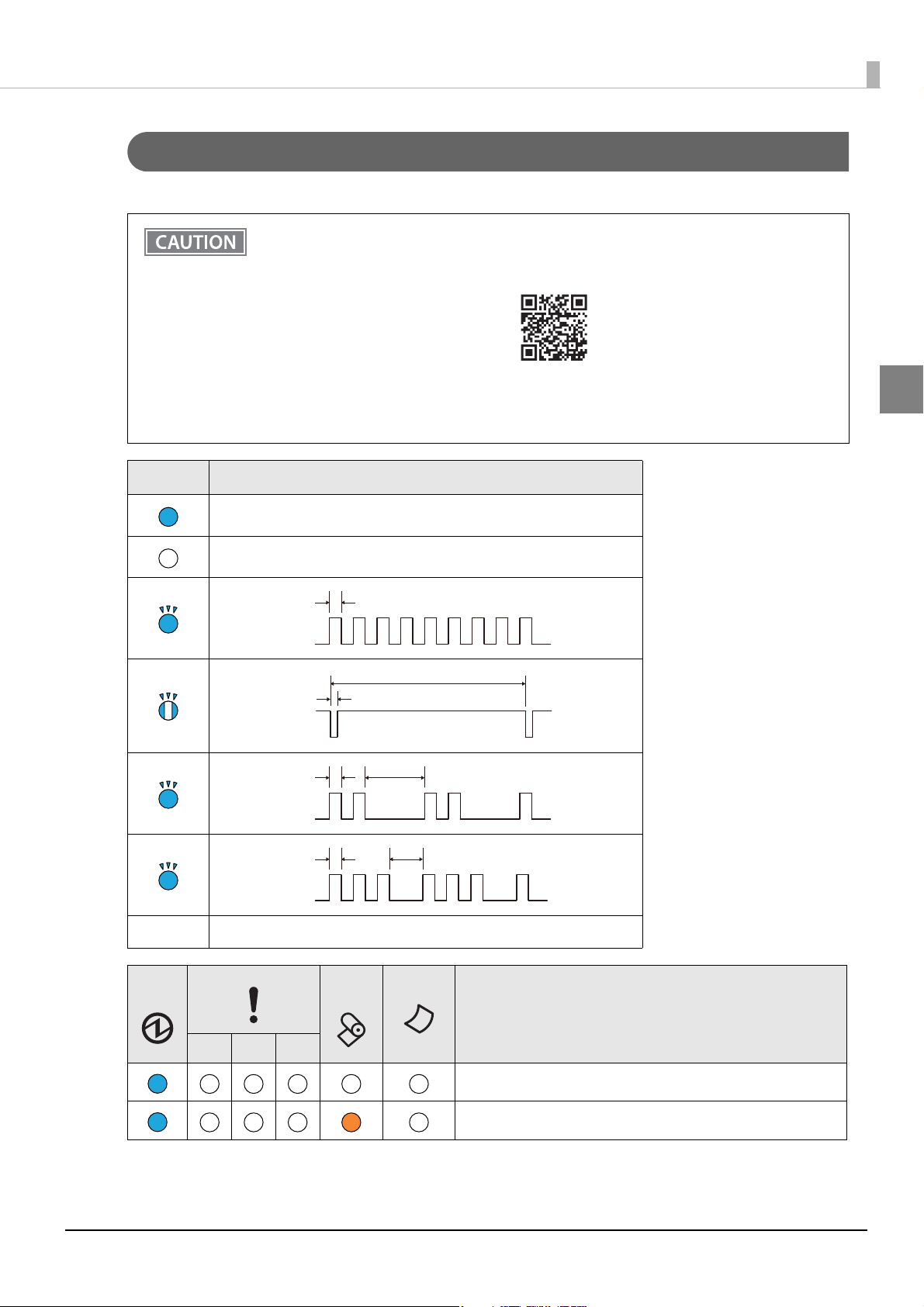
LED on/flashing patterns
ON
OFF
0.32 s
ON
OFF
0.16 s
5.12 s
(2)
ON
OFF
0.32 s 1.6 s
(3)
ON
OFF
0.32 s 0.92 s
The status of the printer is indicated by lit and flashing LEDs.
• You cannot print when an error has occurred.
• Or, you can scan the QR code using your smart device to check detailed information about the
error and the solution.
Chapter 1 Product Overview
www.epson-biz.com/manuals/tmh6k5-led/
• Refer to troubleshooting for the patterns displayed when an error occurs.
(See
"LED on/flashing patterns" on page 110.)
Mark Status of LED
On
Off
Flashing
Flashing
Flashing
1
Flashing
- LED either on, off or flashing
Power
Error LED
LED
1 2 3
Paper
LED
Slip LED
Printer Status
Online (Normal status)
Roll paper near end
20
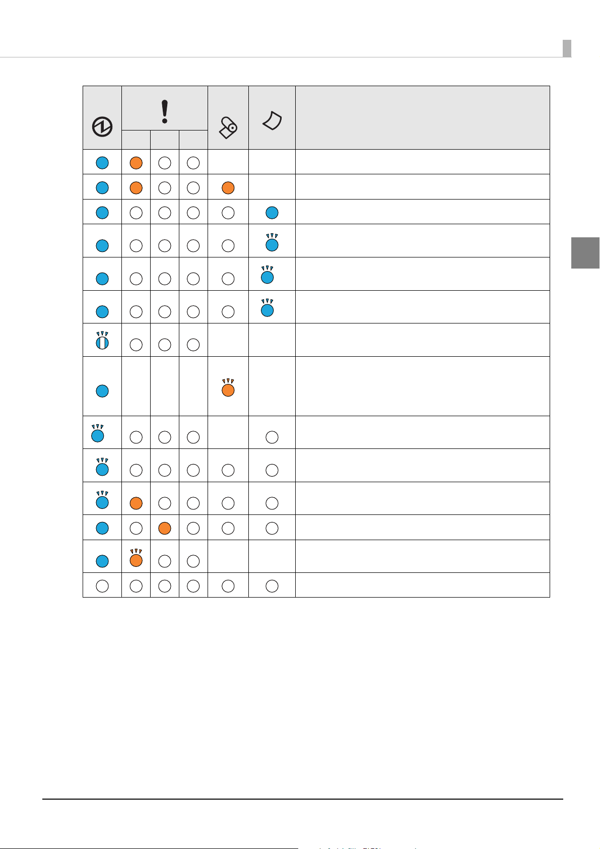
Chapter 1 Product Overview
(2)
(3)
(2)
Power
LED
Error LED
1 2 3
--- -
Paper
LED
Slip LED
--
-
--
Printer Status
Roll paper cover or front cover open when not printing
No paper
Slip paper selection/printing conditions
Slip paper insertion standby
1
Slip paper removal standby
Check insertion standby (Only MICR model)
TM-Intelligent function warning
• Continued self-test standby
• Macro execution standby
• Standby for closing roll paper cover when printing status
sheet
-
--
Bluetooth searchable (1 minute)
Updating firmware
Powering off
Power OFF standby
Errors that recover automatically
The power is off or is not being supplied
21
Chapter 1 Product Overview
NV Memory
The printer's NV memory (Non-Volatile Memory) stores data even after the printer power is turned off. NV
memory contains the following memory areas for the user:
• NV graphics memory
• User NV memory
• Memory switches
• R/E (Receipt Enhancement)
• Maintenance counter
NV memory can be rewritten about 100,000 times. As a guide, NV memory rewriting should be 10
times or less a day when you program applications.
CAUTION
NV Graphics Memory
1
Graphics, such as shop logos to be printed on receipts, can be stored. Even with a serial interface model whose
communication speed is low, high speed graphics printing is possible.
To register your graphics data, use TM-H6000V Utility or ESC/POS commands.
You can check registered graphics data using TM-H6000V Utility or by printing the data in the NV graphics
information print mode.
User NV Memory
You can store and read text data for multiple purposes, such as for storing a note including customizing or
maintenance information of the printer.
Memory Switches
With the memory switches, which are software switches for the printer, you can configure various settings of the
printer. For information about the memory switch, see
"Software Settings" on page 65.
R/E (Receipt Enhancement)
You can set the graphics data, such as a shop logo, registered in the NV graphics memory to be printed on the
top of each receipt or to be printed on the bottom of each receipt just before the paper is cut.
To make the settings, use TM-H6000V Utility or ESC/POS commands.
You can check the settings using TM-H6000V Utility or by printing the settings information in the Receipt
enhancement information print mode.
22

Chapter 1 Product Overview
Maintenance Counter
With this function, printer information, such as the number of lines printed, the number of autocuts, and
printer operation time after the printer starts working, is automatically stored in NV memory.
• You can also check the head running length and number of times of autocutting with the self-test
(see
"Self-test Mode" on page 79).
• The maintenance counter values are automatically saved in the NV memory usually every two
minutes (up to four minutes). However, the values are not saved when the printer is in
power-saving mode or when it is turned off without the use of the power switch.
1
23
Chapter 1 Product Overview
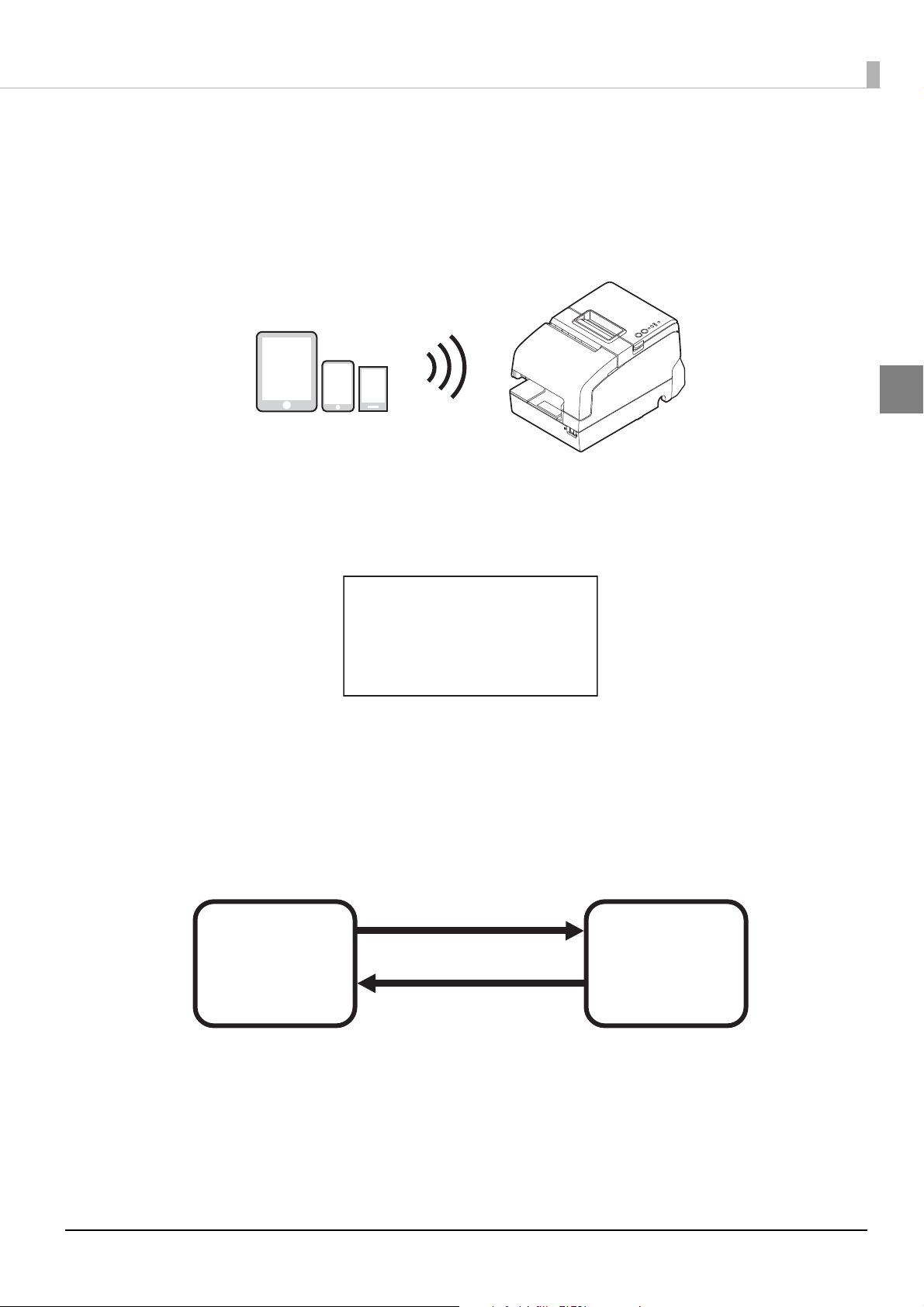
Simple Setup for Wireless LAN
This printer comes with a mode (SimpleAP) that allows printers to connect with a smart device or a computer
without requiring a wireless access point. This allows you to easily setup a wireless LAN for the printer by using
a printer settings tool (Epson TM Utility for iOS/Android or EpsonNet Config) even without a network
environment such as access points.
SimpleAP mode is enabled by default when shipping from the factory. When SimpleAP mode is enabled and
the printer is turned on, the following information is printed automatically.
1
SimpleAP Start
SSID
Encryption Type
Passphrase
IP Address
MAC Address
Although operations are performed in SimpleAP mode during the initial startup, operations switch to standard
mode (infrastructure mode) when changing settings in Epson TM-H6000V Utility for Windows. After
switching, operations continue in standard mode. If you want to make settings in SimpleAP mode again,
initialize the communication settings (see
: EPSON_Printer
: WPA-2-PSK
: 12345678
: 192.168.192.168
: xx-xx-xx-xx-xx-xx
"Resetting the Interface Settings" on page 93).
Changing to standard mode
Ex.) Change IP address,
change SSID
SimpleAP mode
(default setting)
Standard mode
(infrastructure
mode)
Initialize the communication
settings
* You can also set this to standard mode (Ad-Hoc mode) except for the OT-WL06.
24

Chapter 1 Product Overview
Useful Functions for Smart Devices
You can easily connect this product to the network by using the NFC tag built-in to the printer or the QR code
printed on the status sheet.
NFC Tag
Bring a smart device that supports NFC close to the NFC tag to acquire the printer information (information
for specifying the device).
Specify the target printer using the acquired information to connect to the network.
QR Code
Capture the QR code printed on the status sheet with the camera on your smart device to acquire the printer
information (information for specifying the device).
Specify the target printer using the acquired information to connect to the network.
1
• Programming using Epson ePOS SDK is required to use these functions. These functions are
created by combining NFC touch and QR code capturing operations and the target printer
specifications using Printer Easy Select API.
See the "Epson ePOS SDK for Android/iOS User's Manual" and the Epson ePOS SDK sample
program for more details. The sample program also contains a sample implementation method for
reading an NFC tag and capturing a QR code
• You can try a demo of these functions by using Epson TM Utility for iOS/Android.
25
Chapter 1 Product Overview
Printing Using Multiple Interfaces
In printers with multiple interfaces, you can use all interfaces without any limitations on which interface is to be
used. You can use this function to temporarily connect a smart device to a nearby printer and print.
The printer provides each interface with an independent receive buffer and switches the active interface
depending on the priority, while handling data in each receive buffer.
You can set one interface for the main connection. Data received from the main connection interface is handled
with the highest priority.
By default, the interface that receives the first data transfer is set as the main connection interface; however, you
can select the main connection interface in advance.
In the status where all receive buffers are empty for more than the set time (1 second by default), interface
switching is enabled. The interface that receives the data in this status becomes active.
• You cannot use wired and wireless LANs at the same time. When a LAN cable is connected, wireless
LAN is disabled.
• When not using Bluetooth, set the Bluetooth security level to Middle or High in order to prevent
third parties from unauthorized pairing.
You can change the security level with Epson TM Utility, TM-H6000V Utility, or the Interface Setup
mode.
1
You can select the main connection interface and set the time to enable interface switching from the
software settings. For details on software settings, see
When the MICR/Slip/Endorse station is selected, interrupts from other interfaces cannot be
performed.
"Software Settings" on page 65.
26
Setup
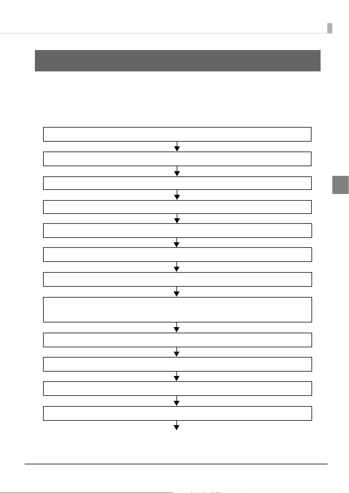
2. Connecting the AC adapter (page 30)
5. Installing the Customer Display (page 45)
4. Connecting the Cash Drawer (page 43)
6. Attaching the Connector Cover (page 46)
1. Removing the Protective Materials and Tape (page 29)
7. Installing and Replacing the Ribbon Cartridge (page 47)
8. Installing and Replacing the Ribbon Cartridge for Endorsement Printing
(page 49)
9. Installing the Roll Paper (page 52)
10. Test Printing (page 54)
3. Connecting the Printer to the Host (page 32)
11. Attaching the Power Switch Cover (page 55)
12. Applying the LED Information Label (page 56)
This chapter describes setup and installation of the product and peripherals.
Flow of Setup
This chapter consists of the following sections along with the setup flow of the product and peripherals.
Chapter 2 Setup
2
27

Chapter 2 Setup
13. RTC Settings (page 58)
14. Adjusting the Paper Roll Near-End Sensor (page 59)
15. Changing the Paper Width (page 60)
2
28
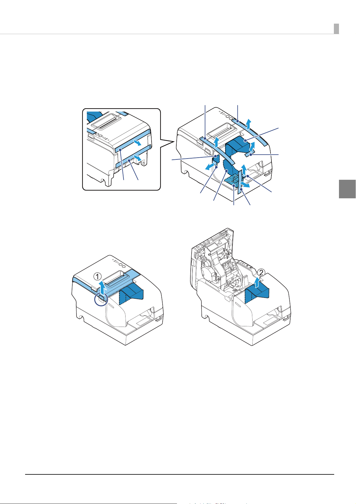
Removing the Protective Materials and Tape
A
B
C
K
L
D
E
F
G
H
I
J
Protective materials and tape are applied for protection against impacts during transportation.
Remove all of them, from A to L.
Note: Tapes K and L may not be attached.
Chapter 2 Setup
2
To remove protective material J, you must open the receipt unit.
29
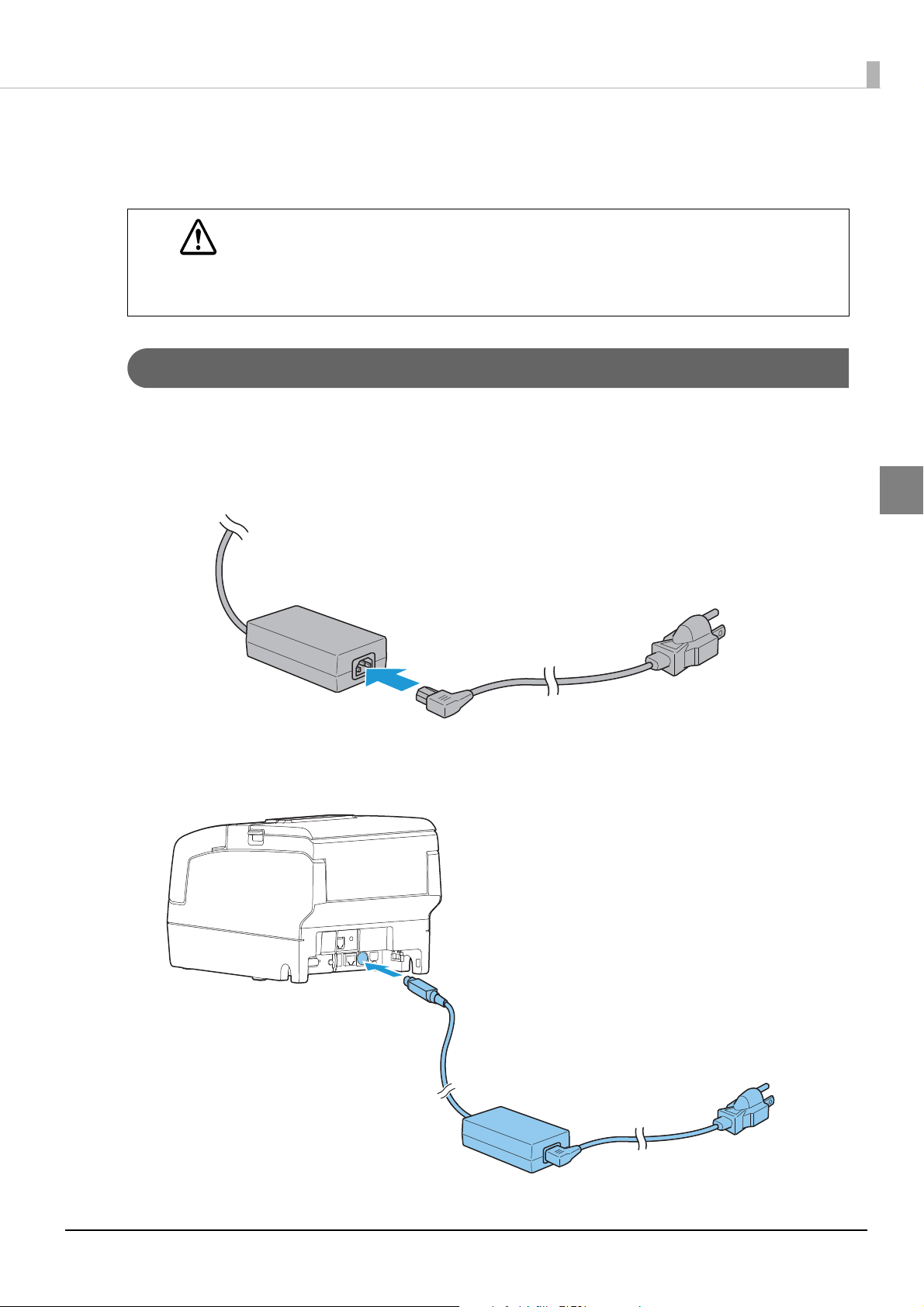
Connecting the AC adapter
Use the Epson PS-180 or an equivalent product as the AC adapter.
• Never insert the AC cable plug into a socket that does not meet the input voltage of the AC
adapter.
WARNING
Connecting the AC adapter
Make sure the printer is turned off.
1
Connect the AC cable to the AC port of the AC adapter.
2
Doing so may result in damage to the printer.
• Should a fault ever occur, immediately turn off the power to the printer and unplug the AC
cable from the socket.
Chapter 2 Setup
2
Connect the DC cable to the printer.
3
30

Insert the AC cable plug into a power outlet.
4
Set the AC adapter so that its label side is facing down.
5
Chapter 2 Setup
2
31

Chapter 2 Setup
locking wire saddle
Connecting the Printer to the Host
• Be sure to install the driver before connecting the printer to the host computer.
• The printer uses modular connectors specifically designed for the cash drawer. Do not connect
these connectors to an ordinary telephone line.
USB Interface
When using the USB interface, fix the USB cable with the locking wire saddle to prevent the USB cable from
coming off.
2
Do not place any weight or stress on the cable when using. Doing so could damage the cable and
connectors.
Ethernet Interface
Use ethernet cable to connect the printer to network via a hub.
Use Epson TM-H6000V Utility for Windows or EpsonNet Config to set network.
For details on Epson TM-H6000V Utility for Windows, refer to TM-H6000V Utility User's Manual.
• When LAN cables are installed outdoors, make sure they are connected through devices that have
surge protection.
Otherwise, the devices can be damaged by lightning.
• Never attempt to connect the drawer kick cable or a standard telephone line cable to the LAN
connector.
• Do not insert the Ethernet cable into the DM-D connector.
32

Chapter 2 Setup
As same with Conventional models, you can use EpsonNet Config (Web version) in the same way.
Start up a web browser and then input the printer's IP address in the address bar.
On the authentication screen, input your user name and password.
The default setting for the password varies depending on the firmware version.
Firmware version User name Password
Before 30.11A/30.11B ESC/POS "epson" "epson"
30.11A/30.11B ESC/POS or later "epson" Product serial number
(10 alphanumeric characters, case sensitive)
You can check the firmware version using the self-test (
You can check the product's serial number using a self-test (
manufacturing nameplate attached to the product.
"Self-test Mode" on page 79).
"Self-test Mode" on page 79) or on the
2
33

Chapter 2 Setup
Wireless LAN Interface
You can connect using a wired cable (LAN/USB), or connect using SimpleAP mode, and setup a wireless LAN
using a TM-H6000V Utility. When setting up multiple printers, you can connect using a wired cable (LAN/
USB) and setup a wireless LAN using the Epson Deployment Tool.
Using Epson TM Utility for iOS/Android, you can easily connect the printer to the network from an iOS or
Android devices.
• When using wireless LAN, make sure you disconnect the LAN cable. If a LAN cable is connected,
wireless LAN is disabled.
• The combinations of wireless LAN cable set and firmware version you can use with this product are
as follows.
Wireless LAN Cable Set Firmware Version
OT-WL02 Until 30.08 ESC/POS, or 30.09A ESC/POS or later
OT-WL05 Until 30.08 ESC/POS, or 30.09B ESC/POS or later
OT-WL06 30.09A ESC/POS or later, or 30.09B ESC/POS or later
You can perform a firmware update by using the TM-H6000V Firmware Updater if using a Windows
computer, or by using the Epson TM Utility if using a smart device. For details, see
page 98
• When you set up the access point at the same time, set the access point in advance and check that
it operates correctly.
• Examine the radio wave situation in the surrounding area before use.
• Avoid using the same channel that is used in the neighboring shops where Wireless LAN is used.
• Wireless LANs with a frequency band of 2.4 GHz interfere with Bluetooth
using Bluetooth and Wi-Fi at the same time, we recommend using 5 GHz.
• When using the printer in environments where kitchen microwaves and other devices that may
interfere radio waves are installed, observe the following points.
• Keep the printer away from the devices, such as kitchen microwaves, that may cause radio wave
interference.
• Use channels that are away from the frequency bands that may cause radio wave interference.
• Place shields between the printer and the devices that may cause radio wave interference.
• Select either 2.4 GHz or 5 GHz, whichever is free from radio wave interference.
• In auto channel setting for the access point, do not select a channel in which the devices may
cause radio wave interference.
• When connecting to a stealth SSID with W53 or W56 using OT-WL06, the following firmware
version is required:
30.12A ESC/POS or later, or 30.12B ESC/POS or later
.
® communication. When
"Utilities" on
2
For SimpleAP mode, see
"Simple Setup for Wireless LAN" on page 24.
34

Chapter 2 Setup
Connecting the Optional Wireless LAN Unit
The optional Wireless LAN cable set (OT-WL02/OT-WL05/OT-WL06) enables you to use the product with a
Wi-Fi connection.
For more information, refer to Technical Reference Guide of the Wireless LAN cable set.
• Be sure to turn off the printer when connecting the Wireless LAN unit.
• Depending on the installation conditions of the printer and the routing for cables connected to it,
the status of the radio waves for the Wireless LAN unit may decline. If this does happen, use an
extension cable.
• This option may be included with this product, depends on the models.
• The shape of the Wireless LAN unit varies depending on the model.
2
35

Setting up Using a SimpleAP Connection from a Windows Computer
Necessary Items
Prepare the following items.
• Computer for setting: Windows 10/8/7/Vista
Computer equipped with a wireless LAN function
• Utility for setting: Epson TM-H6000V Utility for Windows
Follow the steps below to connect the printer.
Turn on the printer.
1
After starting the printer, check that the "SimpleAP Start" is printed. If it is not printed, you need to
enable SimpleAP mode in interface settings mode.
Activate Windows Wireless Network Connection and select [EPSON_Printer] as the
2
connection device on the screen that appears.
If the window to enter a pass phrase appears, enter "12345678".
Default settings on printer are the following values.
Chapter 2 Setup
2
Network mode SimpleAP mode
SSID EPSON_Printer
Pass phrase 12345678
IP Address 192.168.192.168
When connecting to the printer is complete, setup the Wireless LAN using the
3
network setup tool, Epson TM-H6000V Utility for Windows.
For details about Epson TM-H6000V Utility for Windows, see TM-H6000V Utility User's Manual.
When setting the wireless LAN is complete, remove the wired cable (LAN/USB) and
4
restart the printer.
36

Setting up Using a USB Connection from a Windows Computer
Necessary Items
Prepare the following items.
• Computer for setting: Windows 10/8/7/Vista
• Utility for setting: Epson TM-H6000V Utility for Windows
• USB cable
Follow the steps below to connect the printer.
Connect the printer to a PC via the USB cable.
1
Turn on the host computer.
2
Chapter 2 Setup
Turn on the printer.
3
Start up the TM-H6000V Utility for Windows.
4
Select the printer, and then press the [OK] button.
5
If the printer is not displayed, press the "Add Port" button, and then add the printer connected by
USB.
Perform network I/F as well as TCP/IP settings.
6
For details on the settings, see the TM-H6000V Utility User's Manual.
When you have finished making settings, disconnect the USB cable, turn off the
7
printer, and then turn it back on.
To start wireless LAN communication, be sure to disconnect the USB cable, turn off the printer,
and then turn it back on.
2
37

Setting up from a Smart Device
Necessary Items
Prepare the following items.
• Device for setting: iOS or Android device
• Utility for setting: Epson TM Utility for iOS/Android
Running Epson TM Utility for iOS/Android
Run the Epson TM Utility for iOS/Android.
1
Chapter 2 Setup
2
Set from "Wi-Fi Setup Wizard" in the menu.
2
Setup and Operation Workflow
1. Select the network you want to connect to.
2. Enter the passkey.
3. Perform a test print.
Bluetooth Interface
Use a tool, such as a built-in Bluetooth connection tool of your device to establish the connection with the
printer. If your device is a Windows computer, use EPSON TM Bluetooth
pair a terminal and the printer. If your terminal is an iOS or Android terminal, use Epson TM Utility for iOS/
Android to easily pair your terminal and the printer.
• If the host computer and the printer are not connected on a continuous basis but rather connected
every time the printer starts printing, some time may be needed for the printer to actually start
printing after the host computer commands printing. This pause is the time required for
processing the connection between the host computer and the printer, and it depends on the
conditions of the environment where used.
• If data transfer from an application of the host computer has already been completed, data might
remain in the Bluetooth module internal buffer. As such data remaining in the buffer might be lost
when the connection is cut off, use the status or similar functions to check that transmitted data
has been completely printed before cutting off the wireless connection.
®
Connector, which is a utility to easily
38

Setting up from a Windows Computer
• For detailed information about EPSON TM Bluetooth® Connector, see the TM Bluetooth® Connector
User’s Manual.
• The device name and passkey are editable with the Setup Utilities.
Follow the procedure below and make the settings.
Have a Bluetooth wireless technology compatible computer ready.
1
Make sure you have installed TM Bluetooth® Connector.
Turn on the printer.
2
Start TM Bluetooth® Connector.
3
Select [Search all printers around this computer], and then click [Search].
4
Chapter 2 Setup
2
If the printer has not detected after clicking the Search button, check the manufacturer of the
Bluetooth software.
1. Open the Control Panel.
2. In the search box on the Control Panel, enter "Bluetooth", an d th e n c lic k Ch ang e Bluetooth
settings.
3. In the Bluetooth Settings dialog box, click the Hardware tab, and then search for the
Microsoft Bluetooth Enumerator. If it is not found, the Bluetooth software cannot detect the
Epson Bluetooth printer, and you may not be able to connect to the computer.
39

Select the printer to be paired ( Not been paired yet), and then click [Connect].
5
If the window to enter a passkey appears, enter a passkey and click [OK].
6
Chapter 2 Setup
2
Select the port to be used from the pull-down list, and then click [OK].
7
Printing method Port name
APD print queue ESDPRTxxx (TM-TM-H6000V: Queue name)
UPOS ESDPRTxxx (UPOS for TM-H6000V)
ESC/POS command Displayed virtual COM port (e.g. COM4)
The "Connection complete" window appears. Click [Test Printing] to check operation.
8
40

Click [Back to Main screen] to return to the main window.
9
Click the "x" button of TM Bluetooth® Connector to exit.
10
• If "Error" is displayed when you click the [Search] on the TM Bluetooth® Connector, check
whether:
• The Bluetooth adapter is installed to the computer.
• Bluetooth is ON in the Windows settings.
• If the device is not displayed on the TM Bluetooth
Status shows " " after pairing.
Check whether:
• The printer is not turned on.
Turn on the printer.
• The printer is 10 m or further away from the computer.
• Confirm that there is no other wireless device, such as a microwave oven and cordless
telephone, that can interfere with the Bluetooth printer.
• If the printer and the computer are placed in different rooms separated by a wall, move the
printer and/or the computer in the same room.
• The printer may not be detected when the search time is short. Try search again with longer
search time.
• While a computer and printer are communicating, the printer cannot be detected by other
computers. Confirm that the printer to be detected is not communicating with any computer.
Chapter 2 Setup
®
Connector or the TM Bluetooth® Connector
2
Setting up from a Smart Device
Necessary Items
Prepare the following items.
• Device for setting: iOS or Android device
• Utility for setting: Epson TM Utility for iOS/Android
Running Epson TM Utility for iOS/Android
Run the Epson TM Utility for iOS/Android.
1
Set from "Bluetooth Setup Wizard" in the menu.
2
Setup and Operation Work flow
1. Select the printer you want to connect to.
2. Enter the passkey.
3. Perform a test print.
41

Chapter 2 Setup
Serial Interface
When connecting to the host computer through a serial interface (RS-232), connect a serial cable to the printer,
start the host computer, and then turn on the printer.
• When using connectors equipped with screws, tighten the screws on both sides to secure the
connectors firmly.
• When using interface cables equipped with a ground line, attach the ground line to the screw hole
marked "FG" on the printer.
USB Plus Power Interface
When using a USB Plus Power cable to connect with the host device, connect the flat connector of the USB Plus
Power cable to the printer, and the square connector to the device. After starting the host device, turn the
printer on.
When using USB Plus Power Interface, be careful of the following points.
• Do not connect an AC adapter and USB (Type-B) simultaneously.
• Do not remove or insert the USB Plus Power cable while the printer is still on.
2
42

Chapter 2 Setup
With shielded
Drawer kick connector
Printer side
User side
[Drawer kick side]
Drawer open/
close switch
Drawer kick
solenoid
1
2
3
4
5
6
Connecting the Cash Drawer
• Two driver transistors cannot be energized simultaneously.
• Leave intervals longer than 4 times the drawer driving pulse when sending it continuously.
Required specifications of cash drawer
Specifications of drawers differ depending on manufacturer and/or model. When you use a drawer other than
specified, make sure its specification meets the following conditions.
Otherwise, devices may be damaged.
• The load, such as a drawer kick solenoid, must be connected between pins 4 and 2 or pins 4 and 5 of the
drawer kick connector.
• When the drawer open/close signal is used, a switch must be provided between drawer kick connector pins 3
and 6.
• The resistance of the load, such as a drawer kick solenoid, must be 24 Ω or more or the input current must be
1A or less.
2
• Be sure to use the 24V power output on drawer kick connector pin 4 for driving the equipment.
Drawer Connection Diagram
F. G
+24V
Adaptable Connector
RJ12 modular connector
43

Pin assignments
6 5 4 3 2 1
Pin number Signal name Direction
1Frame GND -
2 Drawer kick drive signal 1 Output
3 Drawer kick open/close signal Input
4 +24 V -
5 Drawer kick drive signal 2 Output
6Signal GND -
Connecting the drawer kick cable
Chapter 2 Setup
• Use a shield cable for the drawer kick cable.
• When using cash drawer, make sure to use the power supply for printer (connector pins 4).
WARNING
Connect the drawer kick cable to the drawer kick connector by pressing firmly until the connector clicks into
place.
• Do not insert a telephone line into the drawer kick connector.
Doing so may damage the telephone line or printer.
2
44

Installing the Customer Display
A customer display and DP-502 (customer display fixing plate) can be installed.
When connecting a customer display, set DIP switch 2-2 on the printer to ON.
See
"Setting the DIP Switches" on page 61.
For details, refer to DM-D110/DM-D210 Technical Reference Guide.
The printer uses modular connectors specifically designed for the cash drawer. Do not connect these
connectors to an ordinary telephone line.
Chapter 2 Setup
2
45

Attaching the Connector Cover
Follow the steps below to attach the connector cover to protect cables.
Align 2 projections on the top of the connector cover with holes in the back of the
1
printer.
Push the connector cover forward so that the projections at the bottom of the printer
2
fit properly in the holes in both sides of the connector cover.
Chapter 2 Setup
2
To remove the connector cover, push both sides of the cover inward to remove the holes in both sides of the
cover from the projections at the bottom of the printer.
46

Installing and Replacing the Ribbon Cartridge
Be sure to use the specified ribbon cassette.
Turn the knob on the ribbon cartridge a little in the direction of the arrow marked on
1
the cartridge to remove any slack in the ribbon.
Chapter 2 Setup
2
CAUTION
Turn on the printer.
2
Make sure to note the direction of the arrow marked on the ribbon cartridge when turning the
knob. If it is turned in the reverse direction, the cartridge may be damaged.
47

Open the front cover.
3
Remove the used ribbon cartridge, if there is one.
4
Insert a new ribbon cartridge until it clicks into place.
5
Chapter 2 Setup
2
Turn the knob on the cartridge in the marked direction again to remove any slack in
6
the ribbon.
48

Chapter 2 Setup
Installing and Replacing the Ribbon Cartridge for Endorsement Printing
If your printer is equipped with an endorsement printer, endorsement printing on slip paper is available.
Follow the steps below to install/replace the ribbon cartridge for the endorsement printer.
Be sure to use the specified ribbon cassette.
Turn the knob on the ribbon cartridge a little in the direction of the arrow marked on
1
the cartridge to remove any slack in the ribbon.
2
CAUTION
Turn on the printer.
2
Make sure to note the direction of the arrow marked on the ribbon cartridge when turning the
knob. If it is turned in the reverse direction, the cartridge may be damaged.
49

Open the receipt unit.
3
Remove the used ribbon cartridge, if there is one.
4
Insert a new ribbon cartridge until it clicks into place.
5
Chapter 2 Setup
2
50

Turn the knob on the cartridge in the marked direction again to remove any slack in
6
the ribbon.
Close the receipt unit.
7
Chapter 2 Setup
2
51

Installing the Roll Paper
Be sure to use the specified paper.
Follow the steps below to install the roll paper.
Make sure the printer is turned on.
1
Open the roll paper cover.
2
Chapter 2 Setup
2
Insert the roll paper in the correct direction.
3
52

Pull out some paper, and close the roll paper cover.
4
Chapter 2 Setup
2
Tear off the paper with the manual cutter.
5
53

Chapter 2 Setup
Test Printing
After the printer setup or when the printer is not operating correctly, you can check the printer operation with
test printing. If the printer performs pattern printing following the steps below, the printer is operating
normally.
Test Printing on Ro ll Pa per
To perform test printing on roll paper, execute the self-test.
See
"Self-test Mode" on page 79.
Test Printing on Slip Paper
Insert the roll paper and close all the covers.
1
While pressing the Release button, turn on the printer.
2
(Press and hold the Release button until the Slip LED flashes.)
After the Slip LED flashes, insert the slip paper. The printer prints a rolling pattern on
3
the slip paper, using the built-in character set.
Once printing is completed, the paper is ejected. If your printer is equipped with an
endorsement printer, the printing is done on the slip after the endorsement side.
Once you remove the slip paper, the printer initializes and switches to standard
4
mode.
2
54

Chapter 2 Setup
Attaching the Power Switch Cover
By attaching the power switch cover, you can prevent accidental operations of the power switch.
You can turn on and off the power switch by inserting a sharp-pointed object in the holes on the power switch
cover. To detach the cover, use a sharp-pointed object.
To use this cover, install it as shown in the illustration below.
2
WARNING
If an accident occurs with the power switch cover attached, unplug the power cord immediately.
Continued use may cause fire or shock.
55

Chapter 2 Setup
Applying the LED Information Label
You can use the LED information label to swiftly learn the status of the printer when an error occurs.
Check the printer's LED on/flashing pattern and identify the error type from the LED information label.
Or, you can scan the QR code using your smart device to check detailed information about the error and the
solution.
We recommend applying the LED information label on the reverse side of the front cover following the steps
below.
• Depending on your printer model, the LED information label may already be applied.
2
Open the front cover.
1
• There are 2 types of the LED information label; a label written in English and a label written in
French. Some models do not include the label written in French.
56

Apply the LED Information Label in the position in the figure below.
2
Chapter 2 Setup
2
57

Chapter 2 Setup
RTC Settings
The time for the RTC (Real Time Clock) may be initialized when starting up for the first time. If the time is
initialized, make settings using the Setup Utilities.
For details on making settings using the Setup Utilities, see the TM-H6000V Utility User's Manual.
2
58

Adjusting the Paper Roll Near-End Sensor
Adjustment screw
Positioning plate
Detection lever
Below are two situations where a roll paper NE sensor adjustment is required.
• To adjust the detection position to suit the diameter of the roll paper core used.
• To adjust the detection position of remaining amount of paper.
• Since roll paper cores vary slightly in shape, depending on paper roll design and manufacturing
tolerances, it is impossible to detect the remaining paper exactly.
• Use roll paper with a core inner diameter of 12 mm {0.47"} and outer diameter of 18 mm {0.71"}
so that the NE sensor can detect the remaining paper as accurately as possible.
Follow the steps below to adjust the roll paper near-end detector.
Open the roll paper cover, and remove the roll paper.
1
Loosen the adjustment screw fastening the sensor, and align the upper edge of the
2
positioning plate with the adjustment position.
Adjustment position
Remaining amount of paper
(Outer diameter: mm)
Chapter 2 Setup
2
Upper Approximately. 27 {1.06"}
Lower (Default setting) Approximately. 23 {0.97"}
Tighten the adjustment screw.
3
After adjustment, make sure that the detection lever operates smoothly.
4
59

Chapter 2 Setup
Changing the Paper Width
The printer is initially set to print on 80 mm {3.15"} width paper, but you can change the printer to print on 58
mm {2.28"} width paper by installing the optional roll paper guide.
Follow the steps below to install the roll paper guide.
• Because some parts of the print head and the autocutter contact the platen and they may
become worn out in 58 mm printing, once you change the paper width from 80 mm to 58 mm,
you cannot change it back to 80 mm.
• When changing the paper width, be sure to change the setting for the paper width with the
customized value. To set the customized value, see
Open the roll paper cover.
1
Align 3 projections on the paper guide with the holes in the roll paper holder, and
2
push it until it clicks into place.
"Software Settings" on page 65.
2
60

Advanced Usage
DSW1
(DIP switch 1)
DSW2
(DIP switch 2)
Setting the DIP Switches
On this printer, you can make various settings with DIP switches.
The DIP switches are already set for the current interfaces. Change the setting if necessary.
Functions of the DIP switches differ depending on the interface.
Setting Procedure
Follow the steps below to change the DIP switch settings.
• Before you remove the DIP switch cover, turn off the printer and disconnect all cables.
Otherwise, a short-circuit may cause the printer to malfunction.
CAUTION
• If you open the DIP switch cover, be sure to close the cover and tighten the screw after
adjusting the DIP switch.
Using this product with the cover open may cause fire or electric shock.
Chapter 3 Advanced Usage
• DIP switch settings are enabled only when the power is turned on or the printer is reset via the
interface. If the settings are changed after that, the functions will not change.
• Do not change switches that are fixed to ON or OFF. Otherwise, the printer may not operate
normally.
Make sure the printer is turned off.
1
Unscrew the screw to remove the DIP switch cover from the base of the printer.
2
3
Set the DIP switches, using the tip of a tool, such as a small screwdriver.
3
Replace the DIP switch cover, and screw it in place.
4
61

When a Serial Interface is Connected
DIP Switch Bank 1
Chapter 3 Advanced Usage
SW Function ON OFF
1-1 Data reception error Ignored Prints "?" OFF
1-2 Receive buffer capacity 45 bytes 4 KB OFF
1-3 Handshaking XON/XOFF DTR/DSR OFF
1-4 Word length 7 bits 8 bits OFF
1-5 Parity check Yes No OFF
1-6 Parity selection Even Odd OFF
1-7
1-8 OFF
Baud rate selections
See the "Transmission Speed (DIP Switches 1-7/1-8)"
table below.
Default
setting
ON
Transmission Speed (DIP Switches 1-7/1-8)
Transmission speed (bps: bits per second) SW 1-7 SW 1-8
4800 ON ON
9600 OFF ON
19200 (default setting) ON OFF
38400 * OFF OFF
bps: bits per second
∗ The setting value of the communication conditions of the serial interface set in the software settings is reflected.
The setting value can be specified as 2400, 4800, 9600, 19200, 38400, 57600, and 115200.
3
DIP Switch Bank 2
SW Function ON OFF
2-1 Handshaking (BUSY condition) Receive buffer full
2-2 Customer display (DM-D) connection Connected Not connected OFF
2-3 ∼
2-4
2-5 Reserved (Do not change setting) Fixed to OFF OFF
2-6 Reserved (Do not change setting) Fixed to OFF OFF
2-7 I/F pin 6 reset signal Enabled Disabled OFF
2-8 IF pin 25 reset signal Enabled Disabled OFF
Selects print density
For DIP Switch 2-1 (BUSY condition), see also
See
"Selecting the Print Density (DIP Switches 2-3/2-4)"
on page 64
.
"Selecting the BUSY Status" on page 64.
• Offline
• Receive buffer full
Default
setting
OFF
OFF
OFF
62

When Another Interface is Connected
DIP Switch Bank 1
Chapter 3 Advanced Usage
SW Function ON OFF
1-1 Auto line feed Always enabled Always disabled OFF
1-2 Receive buffer capacity 45 bytes 4 KB OFF
1-3 Reserved - - OFF
1-4 ∼
1-7
1-8 Reserved - - OFF
Reserved (Do not change settings) - - OFF
DIP Switch Bank 2
SW Function ON OFF
2-1 Handshaking (BUSY condition) Receive buffer full
2-2 Customer display (DM-D) connection Connected Not connected OFF
2-3 ∼
2-4
2-5 Reserved - - OFF
2-6 Reserved (Do not change settings) Fixed to OFF OFF
2-7 Reserved (Do not change settings) Fixed to OFF OFF
2-8 Reserved (Do not change settings)
Selects print density
"Selecting the Print Density (DIP Switches 2-3/2-4)"
See
on page 64
.
• Offline
• Receive buffer full
Fixed to ON ON
Fixed to OFF
*
Default
setting
Default
setting
OFF
3
OFF
OFF
∗ Set for USB Plus Power I/F and Bluetooth I/F.
63

Selecting the Print Density (DIP Switches 2-3/2-4)
Function SW 2-3 SW 2-4
Do not set ON ON
Print density (standard) OFF OFF
Print density (medium) ON OFF
Print density (dark) OFF ON
• If the print density is set to "Medium" or "Dark" level, print speed may be reduced.
• The print density can be set with DIP switches (2-3/2-4) or the software settings. (See
Settings" on page 65.)
Selecting the BUSY Status
Chapter 3 Advanced Usage
"Software
With DIP switch 2-1, you can select conditions for invoking a BUSY state as either of the following:
• When the receive buffer is full
• When the receive buffer is full or the printer is offline
In either case above, the printer enters the BUSY state after power is turned on (including resetting
with the interface) and when a self-test is being run.
Printer BUSY Condition and Status of DIP Switch 2-1
Printer status
Offline During the period after power is turned on (including resetting
with the interface) to when the printer is ready to receive data.
During the self-test. BUSY BUSY
When the cover is open. - BUSY
During paper feed with the Feed button. - BUSY
When the printer stops printing due to a paper-end (when
printer has run out of roll paper).
When waiting for the paper Feed button to be pressed before
macro execution.
When an error has occurred. - BUSY
When the receive buffer becomes full. BUSY BUSY
DIP SW 2-1
ON OFF
BUSY BUSY
-BUSY
-BUSY
3
64

Chapter 3 Advanced Usage
Software Settings
With the memory switches and customized values, which are software settings for this printer, you can set the
various functions.
For an outline of the functions, see the following section. Use the methods shown in the table below, or ESC/
POS commands for the settings.
Item\Method
Auto line feed
Power saving function for USB
Paper sensors to output paper end signal
Error signal output
Select paper sensor(s) to stop printing
Memory Switches
Selection of interface using the customer display
Power ON information
User NV memory capacity
NV graphics memory capacity
Roll paper width
Receipt print density
Receipt print speed
Character code table defaults
Software
Setting
Mode
✔✔✔
✔✔✔
✔✔✔
✔✔✔
✔✔✔
✔✔✔
✔✔✔
✔ --
✔ --
✔✔✔
✔✔✔
✔✔✔
✔✔ -
TM-H6000V
Utility for
Windows
Epson TM
Utility for
iOS/Android
3
International character defaults
Command execution during offline
Interface selection
Interface switch wait time
Main interface selection
Startup Display
Customized Values
Power supply unit capacity
Column emulation mode
Autocutting at roll paper cover close
Automatic paper reduction
Auto replacement of font
Print density during multi-tone printing
Method for canceling recoverable error
Transmission speed for serial interface
Reset Bluetooth Settings
✔✔ -
✔✔✔
✔ --
✔✔✔
✔✔✔
✔✔✔
✔✔✔
✔✔✔
✔✔✔
✔✔✔
✔ --
✔✔✔
✔✔✔
✔✔ -
✔ --
65

Chapter 3 Advanced Usage
Item\Method
Bluetooth communication interval during power
saving mode
Cut Error Release Method
Logo
ePOS-Print
ProxyInfo
Server Direct Print
Status Notification
Network CS Authentication
Network Dev Info
Ethernet Config
Wi-Fi Config
SSL/TLS Config
Certificate Config
TCP/IP Config
Software
Setting
Mode
✔✔✔
- ✔✔
- ✔✔
- ✔✔
- ✔✔
- ✔✔
- ✔✔
- ✔✔
- ✔✔
- ✔✔
- ✔✔
- ✔ -
- ✔ -
- ✔✔
TM-H6000V
Utility for
Windows
Epson TM
Utility for
iOS/Android
3
SNMP Config
Time Config
LPR Config
Port9100 Config
IP/Port Filter Config
- ✔✔
- ✔✔
- ✔✔
- ✔✔
- ✔✔
• The software setting mode is the mode set using the printer's panel. For details on panel
operations, see
• For details about the items that can be set with ESC/POS commands and the setting method,
see the ESC/POS command reference.
"Software Setting Mode" on page 82.
66

Functions
Automatic line feed
• Normally disabled (default setting)
• Normally enabled
USB power saving function
• Enabled (default setting)
• Disabled
Paper sensors to output paper end signal
• Roll paper out detector (default setting)
• Disabled
Chapter 3 Advanced Usage
Error signal output
• Enabled (default setting)
• Disabled
Select paper sensor(s) to stop printing
• Enabled (default setting)
• Disabled
Selection of interface using the customer display
Specify the printer interface for when using the customer display.
• Serial interface only.
• All interfaces that can be used. (default setting)
Power ON information
• Enabled
• Disabled (default setting)
3
User NV memory capacity
Select one of the following.
1KB (default setting)/ 64KB/ 128KB/ 192KB
67

NV graphics memory capacity
Select one of the following.
None (0KB)/ 64KB/ 128KB/ 192KB/ 256KB/ 320KB/ 384KB (default setting)
Roll paper width
• 80mm (default setting)
• 58mm
• Be sure to install the roll paper guide (model: PG-58II) when you select the 58 mm paper width.
(See
"Changing the Paper Width" on page 60.)
• Because some parts of the print head and the autocutter contact the platen and they may
become worn out in 58 mm printing, once you change the paper width from 80 mm to 58 mm,
you cannot change it back to 80 mm.
Receipt print density
Chapter 3 Advanced Usage
Selectable from 70 to 130% (5% increment)
Default setting: Depends on the DIP switch settings
The specified original paper types and recommended print densities are as indicated below.
Depending on the paper type, it is recommended to set the print density as shown in the table below for the best
print quality.
Original Paper type Density Print speed
AF50KS-E 4 (85%) 13 (300 mm/sec)
P220AGB-1 5 (90%) 13 (300 mm/sec)
TF50KS-EY 5 (90%) 14 (350 mm/sec)
P35524 6 (95%) 13 (300 mm/sec)
P160R, KT55FA 7 (100%) 14 (350 mm/sec)
TF60KS-EY, PD190R, KT48FA, F5041(55), F5041(48) 7 (100%) 13 (300 mm/sec)
P30521, P30523, P31523 8 (100%) 13 (300 mm/sec)
• When the print density level is increased, print speed may be reduced. When printing at a
density of 115% or more and below a room temperature of 15°C, the speed drops to less than
200 mm/sec.
• When setting the print speed to level 14, use customized values to set the print density.
3
68

Receipt print speed
Selectable from levels 1 to 14 (Slow ~ Fast)
Default setting*: level 13 or 14
∗ Varies depending on the model.
Depending on print conditions, such as print duty, print head temperature, and data transmission
speed, print speed is automatically adjusted, which may cause white lines due to intermittent print
(the motor sometimes stops). To avoid this, keep the print speed constant by setting it lower.
Character code table defaults
Selectable from 43 pages including user defined page
Default setting: PC437: USA, Standard Europe
International character defaults
Selectable from 18 sets
Default setting: USA
Chapter 3 Advanced Usage
Command execution during offline
• Enabled
• Disabled (default settings)
Interface selection
• UIB (Serial, USB Plus Power, and Bluetooth*)
• Built-in USB
• Ethernet /Wi-Fi (When installing an interface)
• Auto: Built-in USB automatic switching
• Multiple: All interfaces enabled (default setting)
∗ Only for Bluetooth model.
Interface switch wait time
Select from 1 to 10 seconds (in intervals of 1 second)
1 second (default setting)
3
69

Main interface selection
• Auto: interface that receives data first (default setting)
• UIB (Serial, USB Plus Power, or Bluetooth)
• USB
• Wi-Fi or Ethernet
• No main connection I/F
When not using Bluetooth, set the Bluetooth security level to Middle or High in order to prevent
third parties from unauthorized pairing.
You can change the security level with Epson TM Utility, TM-H6000V Utility, or the Interface Setup
mode.
Startup Display
• Enabled
• Disabled (default setting)
Chapter 3 Advanced Usage
Power supply output
Selectable from levels 1 to 3 low power load
Default setting: level 3
Column emulation mode
• Standard column mode (default setting)
• 46-column mode
Autocutting at roll paper cover close
• Cuts
• Does not cut (default setting)
Automatic paper reduction
Extra upper space reduction
• Disabled (default setting)
• Enabled
3
Extra lower space reduction
• Disabled (default setting)
• Enabled
Line space reduction rate
• Not reduced (default setting)
70

• Reduce 25%
• Reduce 50%
• Reduce 75%
Line feed reduction rate
• Not reduced (default setting)
• Reduce 25%
• Reduce 50%
• Reduce 75%
Amount of reduction in character height
• Not reduced (default setting)
• Reduce 25%
• Reduce 50%
• Reduce 75%
Chapter 3 Advanced Usage
Amount of reduction in barcode height
• Not reduced (default setting)
• Reduce 25%
• Reduce 50%
• Reduce 75%
• No reduction is applied to blank dot lines that exist in a graphic data.
• Reduced barcodes are not guaranteed to be correctly scanned. Make sure to check whether
they are properly read by a barcode reader that is actually used.
Auto replacement of font
• Does not replace (default setting)
• Font A
• Font B
• Font C
Print density during multi-tone printing
Selectable from 70 to 130% (5% increment)
100% (default setting)
3
Method for canceling recoverable error
• Command only (default setting)
• Command + Close cover
71

Chapter 3 Advanced Usage
Transmission speed for serial interface
• 2400bps/ 4800bps/ 9600bps/ 19200bps/ 38400bps (default setting)/ 576000bps/ 115200bps
Bluetooth communication interval during power saving mode
• Level 1 (Standard) (Initial setting)
• Level 2 (Short)
By changing the setting to "Level 2 (Short)," you can shorten the time until printing begins or the
time until information is shown on the customer display connected to the printer.
However, because the communication frequency increases, the power consumption of the printer
and the host also increases.
Also, depending on the host, this setting may not be enabled, and the host-specified
communication interval may be used.
3
72

Setting and reference items shared by Ethernet/Wi-Fi
Chapter 3 Advanced Usage
TM-H6000V
Item Parameter
IP Address 192.168.192.168 * ✔✔✔✔✔
Subnet Mask 255.255.255.0 * ✔✔✔✔✔
Default Gateway
Address
Acquiring the IP
Address
APIPA Enable/Disable Disable ✔✔✔✔ -
ARP+Ping Enable/Disable Disable ✔✔✔✔ -
Administrator
Name
Location/Person (Up to 255
Password (Up to 20
Manual /
Auto (DHCP)
(Up to 255
characters)
characters)
characters)
Default
setting
0.0.0.0 * ✔✔✔✔✔
Auto (DHCP) ✔✔✔✔✔
" " (no value) ✔✔✔✔ -
" " (no value) ✔✔✔✔ -
"epson" ✔✔✔✔ -
Utility
Reference Setting Reference Setting Reference
Web Browser
Status
Sheet
3
Standard
Community
Name
Community
Name
(read only)
Community
Name
(read/write)
Wellknown
Community
Name
IP Trap1 Enable/Disable Disable ✔✔✔✔ -
IP Trap2 Enable/Disable Disable ✔✔✔✔ -
Community
Name
(IP Trap #1)
Community
Name
(IP Trap #2)
read only "public" - - ✔ --
(Up to 31
characters)
(Up to 31
characters)
Enable/Disable Enable ✔✔✔✔ -
(Up to 31
characters)
(Up to 31
characters)
" " (no value) ✔✔✔✔ -
" " (no value) ✔✔✔✔ -
" " (no value) ✔✔✔✔ -
" " (no value) ✔✔✔✔ -
73

Chapter 3 Advanced Usage
TM-H6000V
Item Parameter
IP Trap #1
Address
IP Trap #2
Address
Socket Timeout 1-300 sec / 0
Time Server
Status
Time Server
Address
IP Filter Enable/Disable Disable ✔✔ ---
- 0.0.0.0 ✔✔✔✔ -
- 0.0.0.0 ✔✔✔✔ -
(no timeout)
Success / Failure /Invalid
- 0.0.0.0 ✔✔✔✔ -
Default
setting
90 sec ✔✔✔✔ -
Invalid ✔✔✔✔✔
Utility
Reference Setting Reference Setting Reference
Web Browser
Status
Sheet
∗ Initial value when "Acquiring the IP Address" is set to "Manual".
Setting and reference items for Ethernet
3
Item Parameter
Communication
mode setting
MAC Address - (refer to MAC
Auto Negotiation /
10BASE-T Half /
10BASE-T Full /
100BASE-TX Half /
100BASE-TX Full
Default
setting
Auto
Negotiation
Label)
TM-H6000V
Utility
Reference Setting Reference Setting Reference
✔✔✔✔✔
✔ - ✔ - ✔
Web Browser
Status
Sheet
74

Setting and reference items for Wi-Fi
Chapter 3 Advanced Usage
Item Parameter
SSID (Up to 31
characters)
WPA/WPA2 PreShared Key (Pass
Phrase)
MAC Address - (refer to
Network mode Infrastructure
WLAN Communication Standard
8-63 ASCII characters or max 64
Hexadecimal characters
Ad-Hoc (except for
the OT-WL06)
When using
OT-WL02
(Infrastructure)
802.11b/g/n
Auto
(Ad-Hoc)
802.11b/g
Auto
Default
setting
EPSON_Print
er
EpsonNet - ✔ - ✔ -
WLAN
option's
Label)
Infrastructure ✔✔✔✔✔
(Infrastructure)
802.11b/g/n
TM-H6000V
Utility
Reference Setting Reference Setting Reference
✔✔✔✔✔
✔ - ✔ - ✔
✔✔✔✔✔
Web Browser
Status
Sheet
3
When using
OT-WL05
(Infrastructure)
802.11b/g/n
802.11a/n
Auto
(Ad-Hoc)
802.11b/g
802.11a
Auto
When using
OT-WL06
(Infrastructure)
802.11b/g/n
802.11a/n/ac
Auto
(Ad-Hoc)
Not available
Channel * 1 - 13 1 ✔✔✔✔✔
(Infrastructure)
802.11b/g/n
(Infrastructure)
802.11b/g/n
✔✔✔✔✔
✔✔✔✔✔
75

Chapter 3 Advanced Usage
Item Parameter
Security Type None/ WEP (64)
WEP (128)/
WPA-PSK (AES)/
WPA2-PSK/
WPA2-Enterprise
Authentication
Algorithm
Default WEP Key key1 - key4 key1 ✔✔✔✔ -
WLAN Power
Save
Open System/
Shared Key/ Auto
Enable/Disable Disable ✔✔✔✔ -
Default
setting
WPA2-PSK ✔✔✔✔✔
Open System ✔✔✔✔ -
Utility
Reference Setting Reference Setting Reference
TM-H6000V
Web Browser
Status
Sheet
∗ Channel setting is only available for Ad-Hoc mode. Channels available for use vary depending on the country.
Setting and reference items for Bluetooth
TM Utility
for
Android
Item Parameter
Default
setting
TM-H6000V
Utility
Status
Sheet
TM Utility
for iOS
3
BD address * - (refer to a Status
Sheet)
Bluetooth passkey 4 to 16 charac-
ters
0 to 9, A to F
Bluetooth device
name
Auto Re-Connect
with iOS device
Security Low
Communication
interval during
power saving
mode
1 to 31Byte
20H,21H,23H
to 7EH
(Hexadecimal)
Disabled
Enabled
Middle
High
Standard
Short
"0000" ✔✔✔✔
"TM-H6000V_xxxxxx"
(xxxxxx is the final six
digits of the product
serial number.)
Enabled ✔✔✔ -
Low ✔✔✔✔
Standard ✔✔✔✔
∗ Settings cannot be changed for BD address.
✔✔✔✔
✔✔✔✔
76

Chapter 3 Advanced Usage
Setting/Checking Modes
As well as print mode, the following modes are also provided for making various printer settings and checking
items.
• Self-test mode
• NV graphics information print mode
• Receipt Enhancement information print mode
• Software settings mode
• Restore default values mode
• Interface setup mode
• TM-Intelligent settings information print mode
• Peripheral Device Information Print Mode
• Hexadecimal dumping mode
The self-test mode or hexadecimal dumping mode is selected depending on the operation performed when the
power is turned on.
NV graphic information print mode, Receipt Enhancement information print mode, Software settings mode,
and Restore default settings mode are selected depending on the Feed button operation performed during a
self-test.
Close all the covers, and turn on the printer while pressing the Feed button.
Self-test
Briey press the Feed button. Hold down the Feed button.
Continuing the self-test
Press the Feed
button once briey
and then hold it
down.
NV Graphics
Information
Open the roll paper cover, and turn on the printer while pressing the Feed
Press the Feed
button twice briey
and then hold it
Enhancement
Information
button, and close all the covers.
Hexadecimal dumping
Mode selection guidance
down.
Receipt
Press the Feed button
three times briey
and then hold it
down.
Software Settings
Press the Feed
button four times
briey and then hold
it down.
Restore Default
Values
Press the Feed button
ve times briey and
then hold it down.
Interface Setup
Press the Feed
button six times
briey and then hold
it down.
TM-Intelligent
settings information
print
Press the Feed
button seven times
briey and then hold
it down.
Peripheral Device
Information print
3
77

Chapter 3 Advanced Usage
Mode Selection
Modes
0: Exit and Reboot Printer
1: NV Graphics Information
2: Receipt Enhancement Information
3: Customize Value Settings
4: Restore Default Values
5: Interface Setup
6: TM-Intelligent Information
7: Peripheral Device Information
8 or more: None
Select Modes by executing following
procedure.
step 1. Press the Feed button less
than 1 second as many times
as the selected mode number.
step 2. Press Feed button for 1
second or more.
In 1 and 2, the following guidances are printed, the Paper LED flashes, and instructs the user's operations.
1. Continuing self-test guidance
2. Mode selection guidance
3
78

Self-test Mode
You can check the following items using the self-test.
• Product name
• Control firmware version
• Product serial number
• Interface information
• Customer display setting
• Built-in character fonts
• Automatic line feed setting
• Print density setting
• Usable device
• Recovery point information
• Maintenance information
• DIP switch settings
Chapter 3 Advanced Usage
Follow the steps below. You can also run the self-test using the ESC/POS commands.
Make sure all the covers are closed.
1
While pressing the Feed button, turn on the printer. (Hold down the Feed button
2
until printing starts.)
After printing the current print status, a Continuing self-test guidance is printed, and the
Power LED flashes.
Briefly press the Feed button (less than one second) to continue the self-test.
3
The printer prints a rolling pattern on the roll paper, using the built-in character set.
After "*** completed ***" is printed, the printer initializes and switches to standard mode.
3
79

Chapter 3 Advanced Usage
NV Graphics Information Print Mode
Prints the following NV graphic information registered to the printer.
• Capacity of the NV graphics
• Used capacity of the NV graphics
• Unused capacity of the NV graphics
• Number of NV graphics that are registered
• Key code, number of dots in X direction, number of dots in Y direction to be defined.
• NV graphics data
For details on NV graphics, see "NV Graphics Memory" on page 22.
Follow the steps below.
After running a self-test, hold down the Feed button for at least one second, and then
1
select the Mode selection.
The Mode selection guidance is printed, and the Paper LED flashes.
After briefly (less than one second) pressing the Feed button once, hold it down for at
2
least one second, to print the NV graphics information.
After information printing, the Mode selection guidance is printed again.
To finish, turn off the power, or select "Exit and Reboot Printer".
3
3
80

Chapter 3 Advanced Usage
Receipt Enhancement Information Print Mode
You can check the following items using the R/E information mode:
• Automatic top logo setting
• Automatic bottom logo setting
• Extended settings for automatic top/bottom logo
Follow the steps below.
After running a self-test, hold down the Feed button for at least one second, and then
1
select the Mode selection.
The Mode selection guidance is printed, and the Power LED flashes.
After briefly (less than one second) pressing the Feed button twice, hold it down for
2
at least one second, to print the R/E information.
After information printing, the Mode selection guidance is printed again.
To finish, turn off the power, or select "Exit and Reboot Printer".
3
3
81

Software Setting Mode
Set the printer's memory switches and customized values.
• Print density
• Print speed
• Auto reduction of amount of paper to use
• Enabling/disabling paper autocutting at cover close
• Paper width setting
• Character Code/Auto replacement of font
• Default Character CodePage
• Default International Character Set
• Auto replacement of font
• Interface Selection
• Interface setting
• Communication conditions using a serial interface
Chapter 3 Advanced Usage
• Communication conditions using a USB interface
• Interface switch wait time
• Main interface selection
• Automatic line feed
• Enabling/disabling Display when interface is activating
• Command execution (offline)
• Power supply capacity
• Other settings
• Printer model name
• LED indicator when I/F starting
• Column Emulation
• Error Control
• Power on notice
• NV Capacity
For details on the memory switches and customized values, see "Software Settings" on page 65.
3
82

Chapter 3 Advanced Usage
Follow the steps below.
After running a self-test, hold down the Feed button for at least one second to enter
1
the Mode selection.
The Mode selection guidance is printed, and the Paper LED flashes.
Briefly press the Feed button three times (less than one second), hold it down for at
2
least one second to enter the Software settings mode (Customized value setting).
The Software setting mode guidance is printed, and the Paper LED flashes.
After briefly pressing the Feed button (less than one second) for the number of times
3
shown in the print result, hold down the button for more than one second to select
the setting items.
The setting selected as the setting item, the current settings and default settings are printed.
Depending on the setting item, you may need to continue selecting the setting item before the
settings are printed.
When set to a value other than those in the software setting mode, the current settings are not
printed.
Select a setting by briefly pressing the Feed button (less than one second) for the
4
number of times applicable to the setting, and then hold down the button for more
than one second to confirm your selection.
After saving the settings, the Software setting mode guidance is printed, and the Paper LED flashes.
To close Software setting mode, turn off the printer, or select "Exit" to return to Mode
5
selection guidance, and then select "Exit and Reboot Printer".
• To select 0 as the item number, hold down the Feed button until printing starts.
• If the button is pressed a number of times that is not displayed by the Setup guidance, the
operation is invalid and the same guidance is printed.
3
83

Chapter 3 Advanced Usage
Restore Default Values Mode
In Restore default values mode, following values saved on NV Memory will be set back to default settings.
When any error occurs, you can use to specify the reason.
Setting Contents Setting Items
Customized value ✔✔
Memory switch ✔✔
R/E (Receipt Enhancement) settings ✔✔
Communication condition of USB interface ✔✔
Communication condition of Bluetooth interface ✔✔
Communication condition of network interface ✔✔
TM-Intelligent function settings ✔✔
NV graphics - ✔
NV bit image - ✔
User-defined page - ✔
User NV Memory - ✔
Bluetooth low energy technology settings - ✔
Restore Default Values
and Delete Defined Data
3
Follow the steps below.
After running a self-test, hold down the Feed button for at least one second to enter
1
the Mode selection.
The Mode selection guidance is printed, and the Paper LED flashes.
Briefly press the Feed button four times (less than one second), hold it down for at
2
least one second to enter the Restore Default Values.
The guidance is printed.
84

Chapter 3 Advanced Usage
When only restoring the default settings:
3
Briefly press the Feed button once (less than one second), hold it down for at least
one second. (Hold down the Feed button until the message of restore completion is
printed.)
When restoring default settings and deleting user defined data:
Briefly press the Feed button twice (less than one second), and then hold it down for
at least one second. (Hold down the Feed button until the restoration complete
message is printed.)
To finish, turn off the power.
4
3
85

Chapter 3 Advanced Usage
Interface Setup Mode
Use this mode to setup the interface and other settings.
Follow the steps below.
After running a self-test, hold down the Feed button for at least one second to enter
1
the Mode selection.
The Mode selection guidance is printed, and the Paper LED flashes.
Briefly press the Feed button five times (less than one second), hold it down for at
2
least one second to enter the Interface Setup mode.
The guidance is printed.
After briefly pressing the Feed button (less than one second) for the number of times
3
shown in the print result, hold down the button for more than one second to select
the setting items.
Reset to Factory Default
Select [Wi-Fi & Ethernet Setup] or [Bluetooth Setup] and select [Reset to Factory Default] to reset the network
setting parameter. The printer is reset and restarted.
SimpleAP mode (Wi-Fi model)
In Wi-Fi model, select [Wi-Fi & Ethernet Setup] and select [SimpleAP] to start in SimpleAP mode (the same as
the factory default setting). The printer is reset and restarted, and it begins printing the "SimpleAP Start"
information.
Select this to use Quick connection for Wi-Fi model.
For information on the Quick connection function, see "Simple Setup for Wireless LAN" on page 24.
Auto re-connect to iOS device (Bluetooth model)
In Bluetooth model, select [Bluetooth Setup] and then select [Auto Re-Connect iOS], you can select whether to
enable or disable auto reconnection to iOS devices.
• For details on the auto re-connect function, see
• You can change the settings with Setup Utilities.
"Auto Reconnect Feature" on page 159.
3
86

Chapter 3 Advanced Usage
Bluetooth Security Settings (Bluetooth model)
For Bluetooth models, select [Bluetooth Setup], and then select [Security], and you can change the Bluetooth
security settings.
When the security settings are changed, the link key (pairing information) is removed. If the printer is
already paired with a terminal, unpair them and then pair again.
You can change the settings with Setup Utilities.
Security Pairing Mode Pairing Method
Security Low Pairing is always possible Just Works
Security Middle Pairing is possible for one minute after printing the status sheet Just Works
Security High Pairing is possible for one minute after printing the status sheet Numeric Comparison/
Passkey Entry
Pairing method when the security is set to Middle/High (from the printer)
When the security is set to Middle/High and the printer is ready to be paired, perform the following procedure.
Load paper in the printer, and then turn it on.
1
• Make sure no errors have occurred and that the printer is not off-line.
• You cannot pair the printer while the network is starting up immediately after the power is turned
on.
Open the roll paper cover, hold down the Feed button for at least one second, and
2
then close the roll paper cover.
A status sheet is printed, and the power LED flashes a pattern indicating that pairing
3
is now possible.
• Pairing is possible for one minute after printing the status sheet.
• You can enable pairing also by printing the status sheet by pressing the status sheet button.
Pairing method when the security is set to High (from the host)
When the security is set to High and the printer is ready to be paired, perform the following procedure.
3
Search for the printer on the Bluetooth settings screen on the host device.
1
Select the printer you want to pair with.
2
The printer prints the Passkey.
Check that the printed Passkey and the Passkey displayed on the host device match,
3
and then select "Pairing" on the host device.
87

Chapter 3 Advanced Usage
Bluetooth communication interval during power saving mode
For Bluetooth models, select [Bluetooth Setup], and then select [Low Power Level], and you can change the Bluetooth communication interval during power saving mode settings.
For details, see "Bluetooth communication interval during power saving mode" on page 72.
TM-Intelligent Settings Information Print Mode
This function allows you to print TM-Intelligent setting information currently registered in the printer.
Follow the steps below.
After running a self-test, hold down the Feed button for at least one second to enter
1
the Mode selection.
The Mode selection guidance is printed, and the Paper LED flashes.
Briefly press the Feed button six times (less than one second), hold it down for at
2
least one second to print the TM-Intelligent setting information.
After information printing, the Mode selection guidance is printed again.
To finish, turn off the power, or select "Exit and Reboot Printer".
3
Peripheral Device Information Print Mode
This function allows you to print information for the device currently connected to the printer.
• Customer Display information
• Wi-Fi adapter information
• Bluetooth adapter information
Follow the steps below.
After running a self-test, hold down the Feed button for at least one second to enter
1
the Mode selection.
The Mode selection guidance is printed, and the Paper LED flashes.
3
Briefly press the Feed button seven times (less than one second), hold it down for at
2
least one second to print the Peripheral Device Information.
After information printing, the Mode selection guidance is printed again.
To finish, turn off the power, or select "Exit and Reboot Printer".
3
88

Chapter 3 Advanced Usage
Hexadecimal Dumping Mode
In hexadecimal dumping mode, data from the host device is printed in hexadecimal numbers and characters.
By comparing the print outs and the program, you can check whether or not data is being sent to the printer
correctly.
• When there are no characters that correspond to the print data, " . " is printed.
• If you press the Feed button when there is less than one line of print data, one line is printed.
• During hexadecimal dumping mode, applications that check the printer status may not operate
correctly. The printer only returns the status for the "Real-time transmission status" command.
Follow the steps below. Entering the hexadecimal dumping mode is also possible using the ESC/POS
commands.
Open the roll paper cover.
1
While pressing the Feed button, turn on the printer. (Hold down the Feed button
2
until the Error1 LED turns on.)
Close the roll paper cover.
3
From this point, all data received by the printer is printed in the corresponding hexadecimal
numbers and ASCII characters.
Example of printing in hexadecimal dumping mode:
To close hexadecimal dumping mode, turn off the printer after printing is complete,
4
or press the Feed button for three times.
3
89

Printing a Status Sheet
Print the interface settings.
When the power LED is flashing, wait until it remains lit to start printing.
Using the Status Sheet Button
Print the Ethernet and Wi-Fi interface and server access test result.
Follow the steps below.
Check that the printer is turned on.
1
Make sure the roll paper cover is closed.
If there is a connector cover, remove the cover.
2
See "Attaching the Connector Cover" on page 46 for details on removing the connector cover.
Chapter 3 Advanced Usage
Hold down the status sheet button for at least three seconds.
3
The status sheet is printed. After printing, the printer returns to the standard mode.
Using the Feed button
Print the Bluetooth interface*, Ethernet, Wi-Fi interface and server access test result.
∗ This cannot be printed on models not equipped with Bluetooth interface.
Follow the steps below.
Check that the printer is on.
1
Open the roll paper cover.
2
Hold down the Feed button for at least a one second.
3
Close the roll paper cover.
4
The status sheet is printed. After printing, the printer returns to the standard mode.
Bluetooth status sheet printing is not performed in the following instances:
• When connected to the host computer with medium or higher security settings
• From when a pairing request is received until passkey printing starts with high or higher security
settings
• When a printer error occurs with medium or higher security settings
• When printing cannot be performed within one minute after a status sheet printing request
operation with medium or higher security settings
• When a buffer clear command has received via Bluetooth when status sheet printing starts
• When the Bluetooth connection is lost when status sheet printing starts
3
90

Chapter 3 Advanced Usage
BT : XXXXXXXXXXXX
DN : TM-H6000V
BD_ADDR
Passkey
Device Name
Module Ver
Module Info
Mode
Security
: XX:XX:XX:XX:XX:XX
: XXXX
: EPSON Bluetooth Printer
: X.XX
: BT401-XXXXX
: Auto re-connect enable
: Low
Bluetooth
Bluetooth Status
*** Bluetooth Interface ***
et
---Server access test result--Printer
local_printer
Model :TM-H6000V
Connection :Success
Server Direct Print
Server 1
Access Test :Success
Server 2
Access Test :Success
Server 3
Access Test :Success
Status Notification
Access Test :Success
Bluetooth Interface Wi-Fi & Ethernet Interface
* * * Wi-Fi & Ethernet Inter face * * *
Wi-Fi Status
MAC Address
SSID : EPSON_Printer
Network Mode
Comm Standard
Encryption Type
Link Status
Channel
Transmission
Access Point
Signal Level
Wi-Fi
: XXXXXXXXXXXX
WF
:TM-
DN
Ethernet Status
MAC Address
Physical Layer
Link Status
net
Ethern
: XXXXXXXXXXXX
WF
: TM-H6000V
DN
: Unmounted
: Infrastructure
: 802.11b/g/n
: WPA2-PSK
: Unknown
: Unknown
: Unknown
: Unknown
: Unknown
H6000V
: XX-XX-XX-XX-XX-XX
: Auto-negotiation
: Connect
Server access test result
Network
Soft Version : XX.XX
TCP/IP Status
Acquiring
IP Address
Subnet Mask
Default Gateway
Service Status
Other Status
Date/Time
Wi-Fi Device ID
Wi-Fi Region ID
---Server access testing started--Please wait for up to 1 minute…
:
Auto
: XXX.XXX.XXX.XX
: XXX.XXX.XXX.X
: X.X.X.X
: 20XX/XX/XX XX:XX:XX
: Unknown
: 0
3
91

Chapter 3 Advanced Usage
Recoverable errors
Waiting for paper removal
If Power is Turned on During Paper Removal Standby
A status sheet for Slip printer is printed if the power is turned on during paper removal standby.
If this occurs, remove the slip paper. If paper is not set, refer to
any small pieces of paper and any other foreign material.
Example of printing
----------------------------------------------*** Error ***
Cause : (***************)[Error Code]
Position : (**********)
Recovery method :
Open the front cover and pull the blue
lever, then remove the paper.
After that, close the front cover and
recover from the error according to
your system.
If the error can't be resolved please
contact technical support.
-----------------------------------------------
"Slip paper is jammed" on page 123 and remove
3
----------------------------------------------*** Waiting for slip to be removed ***
Recovery method :
Open the front cover and pull the blue
lever, then remove the paper.
-----------------------------------------------
Depending on the product model, this function may not be supported.
92

Resetting the Interface Settings
Follow the steps below to restore the interface settings to the factory default.
• You can return the interface settings to their defaults from the Interface Setup mode. See
"Interface Setup Mode" on page 86 for details on the Interface Setup mode.
• Only network settings are returned to their defaults.
Turn off the printer and close all the covers.
1
If the connector cover is attached, remove the cover.
2
See "Attaching the Connector Cover" on page 46 for details on removing the connector cover.
Hold down the status sheet button while turning on the printer.
3
A message is printed indicating that resetting is being performed, and the printer restarts.
Hold down the status sheet button until the initialization execution message is printed.
Chapter 3 Advanced Usage
3
93

Chapter 3 Advanced Usage
TM-Intelligent Function
This product supports the TM-Intelligent function and has a server direct printing function.
This function can be specified by using the TM-H6000V Utility for Windows. See the TM-H6000V Utility
User's Manual for details.
You can also download a dedicated manual and sample programs from our web site.
Server direct print
The server direct function allows this product to acquire print data from a Web server and then print.
By including print data in a response to request from this product, the Web server application can print to this
product or a TM printer on the network.
The features are as follows.
• You can acquire print data from three different URLs.
• Print data is available in ePOS-Print XML format.
• You can use this product to print to TM printers on a network.
• Only the receipt printing function can be used for server direct printing.
Cannot print the slip printing function, validation printing function and endorsement printing function.
Regarding details on server direct printing, see the Server Direct Print User's Manual.
3
94

Chapter 4 Application Development Information
Application Development Information
This chapter describes how to control the printer and gives information useful for printer application
development.
Controlling the Printer
The printer supports the following command systems:
• ESC/POS
• ePOS-Print XML
• ePOS-Device XML
Users can control the printer by using the followings.
• EPSON Advanced Printer Driver
• EPSON OPOS ADK
• EPSON OPOS ADK for .NET
• EPSON JavaPOS ADK
• Epson ePOS SDK
• Server Direct Print
ePOS-Print XML
ePOS-Print XML is the Epson original control command system for POS printers defined in XML. With ePOSPrint XML commands, you can print in environments where http communication is available and from OS
applications. For detailed information about ePOS-Print XML, see the ePOS-Print XML User's Manual.
ePOS-Device XML
ePOS-Device XML is an Epson original control command system for POS printers and customer displays. It is
defined in XML. Control the customer display that is connected to this printer, and control receipt printing, slip
printing, or MICR reading. An application creates a request message in XML format and sends it to this product
using socket communications. For detailed information about ePOS-Device XML, see the ePOS-Device XML
User's Manual.
4
ESC/POS
ESC/POS is the Epson original printer command system for POS printers and customer display. With ESC/POS
commands, you can directly control all the printer functions, but detailed knowledge of printer specifications or
combination of commands is required, compared to using drivers and applications.
For detailed information about ESC/POS commands, see the Product Specifications. Product Specifications is
available after contracting the non-disclosure agreement with Epson. For details, please contact the selling
agency.
95

Chapter 4 Application Development Information
Controlling the Cash Drawer
A pulse output is sent to drawer kick connector pin 2 or pin 5, and you can open the drawer.
You can also check the open/close status of the drawer by checking the signal level of the drawer kick connector
pin 3. These controls are executed by a driver or by commands.
ESC/POS Commands
Prepare the output command for the specified pulse and the status transmission command.
For detailed information about ESC/POS commands, see the Product Specifications. Product Specifications is
available after contracting the non-disclosure agreement with Epson. For details, please contact the selling
agency.
Windows Printer Drivers
You can set so that the drawer opens at the start/end of printing or start/end of a page. For details, see the
manual for drivers.
For details on control, see the manual for Status API of the driver.
OPOS (OCX Driver)
Register a cash drawer using the SetupPOS Utility, and control using the OpenDrawer method or the DirectIO
function.
For details, see the "EPSON OPOS ADK MANUAL APPLICATION DEVELOPMENT GUIDE Cash Drawer"
and the "UnifiedPOS Specification".
OPOS for .NET
Register a cash drawer using the SetupPOS Utility, and control using the OpenDrawer method or the DirectIO
function.
For details, see the "EPSON OPOS ADK for .NET MANUAL Application Development Guide Cash Drawer
(EPSON Standard)" and the "UnifiedPOS Specification".
JavaPOS
Register a cash drawer using the SetupPOS Utility, and control using the OpenDrawer method or the DirectIO
function.
For details, see the "EPSON JavaPOS ADK MANUAL Application Development Guide Cash Drawer (EPSON
Standard)" and the "UnifiedPOS Specification".
Epson ePOS SDK
4
The output command for the drawer kick pulse and the status transmission command are provided in each
SDK library. For details, see the user's manuals provided with each SDK.
• Whether or not pin 2 or pin 5 operates the drawer kick connector depends on the connected cash
drawer.
• You can acquire documents regarding the UnifiedPOS from the following link.
https://www.omg.org/retail/unified-pos.htm
Server Direct Print
Prepare the output command for the specified pulse and the status transmission command.
For details, see the "Server Direct Print User's Manual".
96

Chapter 4 Application Development Information
Software
The following software is provided for application development.
Development Kits
Software Description
EPSON OPOS ADK This OCX driver can control POS peripherals using OLE technology. *
Because controlling POS peripherals with vendor specific commands is not required
on the application side, efficient system development is possible.
EPSON OPOS ADK for .NET The OPOS ADK for .NET is a POS industry standard printer driver compatible with
Microsoft POS for .NET. It allows you to develop applications that are compatible
with the UPOS (Unified POS) specification. When developing applications, use a
separate development environment such as Microsoft Visual Studio .NET.
EPSON JavaPOS ADK (Windows/
Linux)
Epson ePOS SDK This is a development kit for controlling TM printers from native applications of smart
for Android
for iOS
for Universal Windows apps
for JavaScript
Server Direct Print Server Direct Print function enables the TM printers with SDP (Server Direct Print) sup-
JavaPOS is the standard specification which defines an architecture and device
interface (API) to access various POS devices from a Java based system. Using JavaPOS
standard API allows control with Java based applications of functions inherent to each
device. A flexible design with Java language and JavaPOS enables many different
types of computer systems, such as stand alone or network configuration, to use a
same application. You can use JavaPOS to build applications and drivers
independently of platforms. This allows flexible configurations using thin clients to
meet the system requirements.
devices or web applications. This includes libraries, manuals, and sample programs.
port to obtain the print data from the Web server and print the data. The Web server
application performs printing by including print data in the response to a print
request from the TM printers with SDP support.
*: OLE technology developed by Microsoft divides software into part blocks. The OPOS driver is presupposed
to be used with a development environment, such as Visual Basic, unlike ordinary Windows printer drivers.
It is not a driver to be used for printing from commercial applications.
You can acquire documents regarding the UnifiedPOS from the following link.
https://www.omg.org/retail/unified-pos.htm
4
97

Drivers
Chapter 4 Application Development Information
Software Description
EPSON Advanced Printer
Driver
EPSON TM Virtual Port Driver This is a serial/parallel-USB/LAN conversion driver to make an Epson
In addition to ordinary Windows printer driver functions, this driver has
controls specific to POS. The Status API (Epson original DLL) that monitors printer status and sends ESC/POS commands is also attached to
this driver.
TM/BA/EU printer connected via USB or LAN accessible from a POS
application through a virtual serial or parallel port. It allows you to
directly control devices connected via USB or LAN with ESC/POS commands without making changes in the POS application that controls
devices connected via a serial or parallel interface.
Utilities
Software Description
TM-H6000V Utility A utility for checking and changing various printer settings.
Use this utility to:
• Check the current settings
• Test operation
• Store logos
• Set paper saving
• Set printing control
• Set communication interfaces
• Set the network
• Set the intelligent function
• Save/restore settings
Operating
environment
Windows
Windows
Operating
environment
Windows
4
Epson TM-H6000V Slip Paper
Sensor Adjustment Tool
Epson TM Utility A utility that is available on the App Store or Google Play. Use this to
EPSON TM Bluetooth
Connector
®
This tool is for adjusting the slip paper sensor of the TM-H6000V. Use
this tool if the Slip LED blinks even though slip paper has been
removed from the printer.
perform wireless connection setup and change settings on the printer
from iOS and Android devices. This utility also comes with the
following functions:
• Sample receipt printing
• Customized receipt printing
• Printer status display
• Quick pairing by NFC/QR code
• Easy print by NFC/QR code
• Firmware update
Use to pair a Bluetooth printer and associate the generated Bluetooth
port with that used by the driver and applications.
Windows
iOS, Android
Windows
98

Chapter 4 Application Development Information
Software Description
Epson Deployment Tool Use to make network and printer settings simultaneously. Allows you
to make settings efficiently at the time of introducing TM printers for
the first time, or when configuring multiple TM printers at the same
time.
Epson Monitoring Tool Use to check a list of status for the Epson printers connected to the
network.
You can also update certificates for multiple printers used for
WPA2-Enterprise in a batch.
TM-H6000V Printer Model
Setting Utility
BmpToRaster You can convert BMP image files to multi tone or black and white print
EPSON TMUSB Identifier
Utility
TM-H6000V Firmware
Updater
This tool allows you to change the model name for the TM-H6000V to
TM-H6000IV or TM-H6000V.
command data.
This tool allows you to change the USB identification code (USB Serial
No.). Setting an identification code before replacement makes it easy
to perform replacement if a malfunction occurs.
This tool allows you to update the firmware for the TM-H6000V. Windows
Operating
environment
Windows
Windows
Windows
Windows
Windows
Others
Manual Description
ePOS-Print XML User's Manual Describes ePOS-Print XML statements. This manual comes with sample
programs.
ePOS-Device XML User's Manual Describes ePOS-Device XML statements. This manual comes with sample
programs.
TM-H6000V WebConfig API User's Manual Describes the API for setting this product's TM-Intelligent function. Refer to
this manual when using the API from your application to acquire or change
settings.
Download
You can obtain software and manuals from one of the following URLs.
For customers in North America, go to the following web site and follow the on-screen instructions.
www.epson.com/support/
For customers in other countries and regions, go to the following web site:
www.epson-biz.com/
4
99

Chapter 4 Application Development Information
Application Development and Distribution for iOS
If registering an application that uses Bluetooth in the App Store, Epson must submit an application to Apple in
advance. Please apply for each application you want to register in the App Store from the URL below.
www.epson-biz.com/ais/E/
4
100
 Loading...