

Page 1

Service manual
TM200
Rev. No. : V. 1.10
TM200 Service Manual
Page 2

TM200 Service Manual
Contents
1 Features and General Description ....................................................... - 1 -
1.1 Printer Parts .............................................................................. - 1 -
1.2 Major Component Specifications............................................... - 6 -
1.3 Connectors................................................................................ - 6 -
1.4 Interfaces .................................................................................. - 7 -
1.5 Buttons, Switches, and Panel Lights......................................... - 9 -
1.6 Self-test................................................................................... - 14 -
1.7 Hexadecimal Dump................................................................. - 15 -
1.8 Paper Sensors ........................................................................ - 16 -
1.9 Standard Accessories.............................................................. - 16 -
1.10 Options.................................................................................... - 17 -
1.11 Consumables .......................................................................... - 17 -
1.12 External Power Supply Specifications ..................................... - 17 -
2 Mechanisms and Operation ............................................................... - 19 -
2.1 Component Connections Diagram .......................................... - 19 -
2.2 TM200 Printer Mechanism ...................................................... - 19 -
2.3 Main Circuit Board Unit ........................................................... - 21 -
2.4 I/F Circuit Board Assembly...................................................... - 24 -
2.5 Switch Circuit Board Assembly ............................................... - 24 -
3 Handling, Maintenance, and Repairs................................................. - 25 -
3.1 Handling.................................................................................. - 25 -
3.2 Problem Solving...................................................................... - 28 -
3.3 Clearing Paper Jams............................................................... - 29 -
3.4 Inspection and Maintenance ................................................... - 30 -
4 Troubleshooting ................................................................................. - 32 -
4.1 Symptoms and Solutions ........................................................ - 31 -
4.2 Error Types and Processing .................................................... - 33 -
5 Disassembly, Assembly, and Adjustment ........................................... - 35 -
5.1 Before Starting disassembly, assembly, and adjustment......... - 35 -
5.2 Using this Manual.................................................................... - 35 -
5.3 TM200 Disassembly, Assembly, and Adjustment .................... - 36 -
Door sensor block……………………………………………………- 37 -
Front sensor and paper sensor block………………………….……- 39 -
Autocutter module…………..........…………………………………- 42 -
Thermal head module…............……………………………………- 44 -
Main circuit board….…………………………………………………- 47 -
Appendix A Interface………………………………………………………- 50 -
Appendix B Exploded Diagram ......................................................... - 52 -
Appendix C Panel lights and indicators ........................................... - 53 -
Appendix D Parts number list ........................................................... - 55 -
Page 3
1 Features and General Description
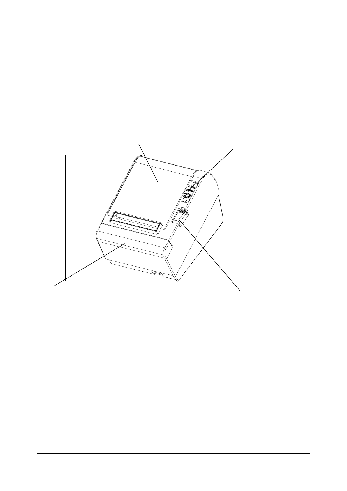
1.1 Printer Parts
Printer cover
Control Panel
TM200 Service Manual
Cutter cover
Cover open button
Figure 1-1 T
M200
ap
pearance
- 1 -
Page 4
TM200 Service Manual
Printing Spe
cifications
Printing method: Thermal line printing
Dot density: 203 dpi x 203 dpi (8 dot/mm)
Printing direction: Unidirectional with friction feed
Printing width: 72mm (2.83”), 576 dot positions
Characters per line (default): 48 (Font A)
64 (Font B)
Character spacing (default): 0.28 mm (0.1”) (2 dots) (Font A)
0.28mm (.01”) (2 dots) (Font B)
Programmable by control command.
Printing speed 180 mm / sec (approxi. 7.1” / sec)
60 lines / sec (computed value for 3.18mm (1/8”) feed)
28.4 lines / sec maximum
(4.23 mm (1/6”) feed, at 24V, 28。C (82。F
),
density level 2)
Paper feeding speed: Approximately 180 mm / sec (7.0”/sec) continuous paper
feeding
Receive Buffer Size 96K Bytes
Number of characters: Alphanumeric characters: 95
International characters: 32
Extended graphics: 128x7pages
(including one space page)
Traditional/ Simplified Chinese, Japanese, Kanji characters
Character structure: Font A: 12 x 24 (including 2-dot spacing horizontally)
Font B: 9 x 17 (including 2-dot spacing horizontally)
Kanji: 24 x 24
Default font: Font A
:
Notes
Printing speed may be sl
of control
commands.
There may be vari
t i
mage is recommended.
bi
Low transmi
ssion
to the printer as quick
C
haract
Font A
12 x 24
24 x 24
B
9 x 17
Kanji
er size:
Standard
W x H (mm) CPL W x H (mm) CPL
1.23 x 2.97
(.05” x .11”)
0.87 x 2.10
(.035” x .08”)
2.97 x 2.97
(.11” x .11”)
* CPL = Characters Per Line
* Space between characters is not included
* Characters can be scaled up to 64 times as large as the standard sizes.
48
64
24
ower depending on th
ations in printing speed. To
speed may
1.23 x 5.92
(.05” x .24”)
0.87 x 4.20
(.035” x .17”)
2.97 x 5.92
(.11” x .24”)
cause in
ly as possible.
Double-height
termittent printing. It is recommended
48
64
24
e data transmission sp
preven
t this for
Double-width
W x H (mm) CPL W x H (mm) CPL
2.47 x 2.97
(.10” x .11”)
1.73 x 2.10
(.07” x .08”)
5.92 x 2.97
(.24” x .11”)
eed and
logo printi
24
32
12
the combi
ng, using a
to
transmit data
Double-weight/
Double-height
2.47 x5.92
(.10” x .24”)
1.73 x 4.20
(.07” x .17”)
5.92 x 5.92
(.24” x .24”)
nation
downl
oad
24
32
12
ed
- 2 -
Page 5

Auto
cutter
Pa
rtia
l cut:
Full cut:
No
te:
Paper Spec
To prevent dot
0.
04 inch) or more befo
ifications
di
splacement, after cutti
re printin
Paper type:
Pa
per ro
Pa
per ro
CAUTION:
Paper must not be pasted to the paper roll.
Printable Area
Form:
Paper width:
ll size:
Roll diameter:
Take-u
ll diam
p pape
eter:
r ro
ll width:
Pa
per roll
Internal Buf
Receive
Non-volatile
Electrical Sp
Supply voltage:
fer
buffer
selectable
bi
t image
ecifications
as 2KB or 96KB
bu
ffer: 128KB
Cutting with
(sel
ect
Cutting without un
ng,
g.
Sp
ecified
Pape
r roll
79
.5 ±0.5 mm (3.13"
Maxi
mum 83 mm
80
+ 0.5 / -1
Inside: 12 mm (0.47")
Outside: 18 mm (0.
The prin
(
3.13"
± 0.02") is 72.2
using the DI
+24
VDC ±
emperature)
t
one poin
able by
ESC I or
paper must be fed ap
therma
.0 mm
table area of a pape
P swit
7%
TM200 Service Manual
t center
GS
cut (sel
l roll pa
± 0.02")
(3.2
7")
71")
± 0.2 mm (2.84" ± 0.008") (576 do
ch.
Cu
rrent
consumption (at 24V, normal
un
cut
V
)
ect
able by
proxi
mately 1 mm (1
per
r with width of
ESC i )
4/360
79.5 ± 0.
or
5 mm
ts)
High-sp
Standby:
Note :
Maxi
eed
mode:
mum 1A for drawer kick-out driving.
(Font A alphanumer
Peak: Approximately 7.8A
Mean: Approximately 0.2A
Mean: Approximately 1.8A
ic character
- 3 -
pr
inting for
all
columns
)
Page 6

EMI and Saf
ety Standards Applied
T
hese standards are only valid
Europe
:
No
rth America:
Oceania:
Co
ndit
ions of acceptab
1. This compo
nent has been judged on the
for Information T
and
1950
submitted
CSA22.2 No. 9
fo
2. T
he terminals and
Reliability
Life
:
MTBF:
MCBF:
External Dimensions an
for products which bear
CE marking: Directive: 89/336/EE
Safety standa
EMI:
Safety standa
EMI:
ility
echnology
rds: EN60950
rds: UL1950/CSA
Equipment
50. sub-clause 2.9, whi
r Listing.
d We
co
nnectors have no
Mechanism:
T
hermal
head:
Autocutter:
ight:
EN550
E
N6100-3-3:1995+A1:2001
EN550
IEC61000 IEC61000-
FCC Class A
AS/N
TM200 Service Manual
a mark or st
C
22:1998 Cla
24:1998, including
C22.2 No.
ZS3548
basis
, i
ncl
ss A
4-2, IEC
61000-4-
4-6, IEC
61000-4-8,
950
of the required
uding Electrica
ch wo
uld
t been evaluated for
15,000
,000 li
nes
10
0 millio
1,200,0
n pulses, 50 Km
00 cuts
atement
3, IEC61000-
spacin
l Busi
on t
he main unit.
4-4, IEC
61000-4-5,
g in the St
ness Equi
cover the component it
field
wiring.
pment, UL
(End of life is defined to have been reached
it reaches t
when
eriod.)
p
360,00
0 hours
(Failure is defined
ccurring during t
o
ur
e period.)
fail
52,000
,000 li
(Thi
s is
an av
ilures rela
fa
ilures up
fa
he begi
nni
as a rand
ng of t
he wear out
om failure
he time of the random
nes
erage failure interval ba
ting to wear out and random
to
the li
fe of 15 m
illion li
andard
self
sed
nes.)
if
on
Height:
Width:
De
pth:
Weig
ht:
Approxi
Ap
Ap
Approxi
(ex
mately 138.7 mm (5.46")
proximately 146.5 mm (5.77")
proximat
cep
ely
195 mm (7.68")
mately 1.4 kg (
t for
the
paper roll)
3.08 lb)
- 4 -
Page 7

Environmen
Temp
Humidity:
tal Conditions
erature:
Op
St
orage:
Op
St
orage:
erating:
erating:
TM200 Service Manual
5
to 45℃
–10
10
10
(41 to
to
50℃ (14 to 122℉)
to
90%
RH
to
90%
RH (e
113℉)
xcept fo
(excep
r paper)
t fo
r paper)
- 5 -
Page 8
1.2 Major Component Specifications
TM200 Service Manual
TM200
Pri
nter Mechanism
Paper Feed Motor
Type:
Drive voltage:
Winding
Print Head
Dot number:
Dot density:
Resistance:
resistan
Unit
ce:
Paper-end Sensor
Paper Roll Near-end Sens
Autocutter Unit
Type:
Cutter motor voltage:
Current consumption:
1.3 Connectors
or
4-ph
24
VDC ± 10
11.5
576
0.
125 mm/do
Av
erag
Reflectio
Reflectio
DC brush moto
24
VDC ± 7%
80
0 mA peak (at
70
mA averag
ase, 48-polarit
%
± 10% at 25
do
ts
t (203
e 600 ± 4.6%
n ty
pe p
n ty
pe p
e (room temper
y, PM-type stepping motor
° C (
hot
hot
r
sta
77° F), pe
DP
o sensor
o sensor
rti
ng,
r phase
I)
low
temperature)
ature)
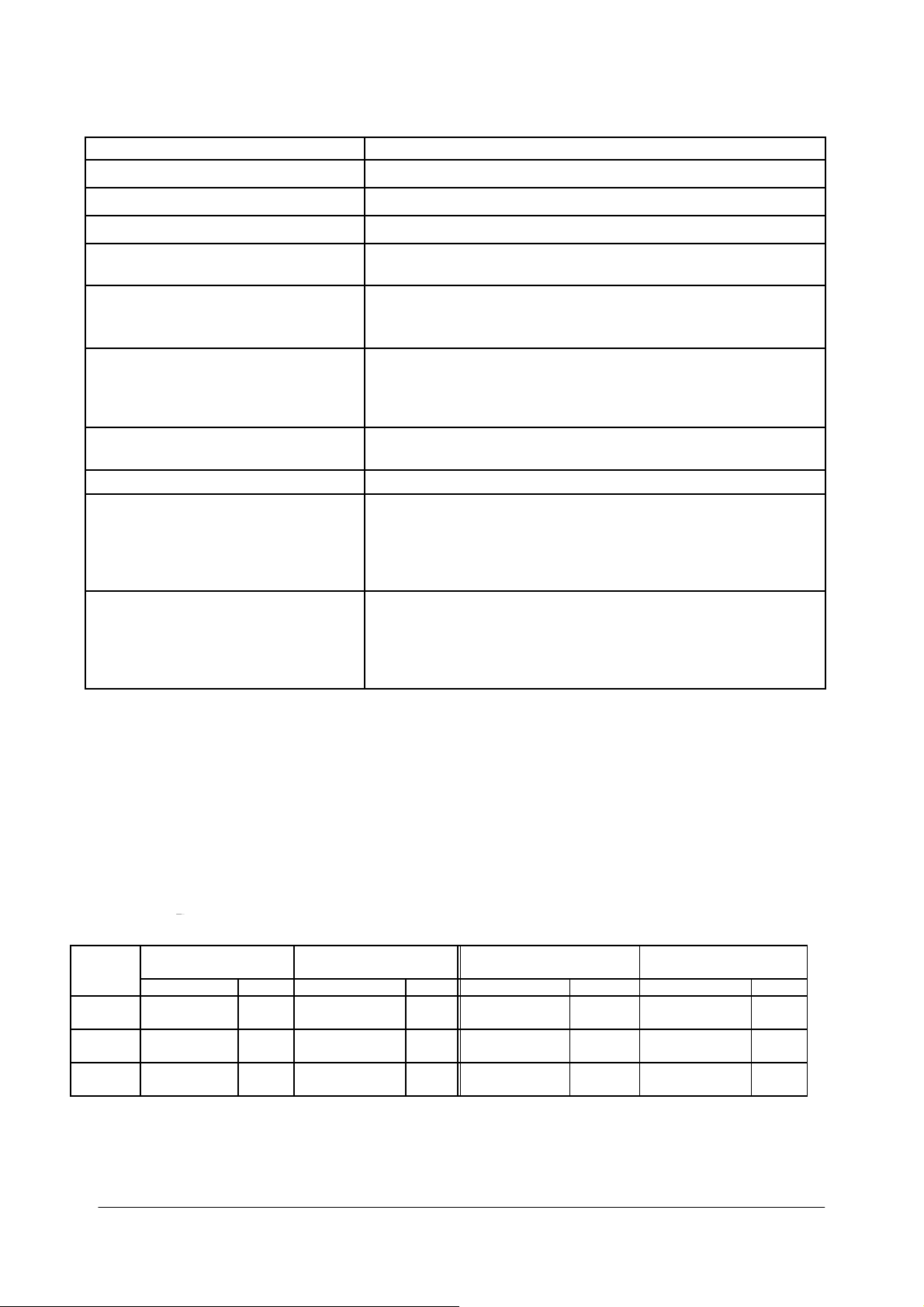
Interface Drawer kick-out Power supply
Power Supp
ly Connector
This co
nnect
or is used
Pin number
1
2 GND
3 NC
Shell
to
connect the pr
S
ignal nam
+
24 VD
C
Frame
GN
inter to an external powe
e
D
- 6 -
Figure 1-2 Power su
r source.
pply connector
Page 9

Drawer Kick
-out Connector
The pu
the host can confirm t
(ASB
lse speci
) comm
fied
ands.
Drawer kick
Pin Number Si
1
2
3
4
5
6
+24 V is
alwa
CAUTION:
Pin
4 must be used only for the drawer.
Figure 1-3 Drawer kick-out
Drawer kick-out driv
Output
CAUTION:
To av
oid an
24 or more.
be
signal: O
over
by
ES
C p
is out
he stat
us of t
-out c
onnector pin
gnal Name
Frame GND
D
rawer kick-out dr
D
rawer open
+24 V
D
rawer kick-out dr
Signal GND
ys output thro
e si
gna
l
current, the resi
put to this connector. For the seri
he inpu
/clo
ugh
co
t si
assi
gnment
ive signal 1
se signal
ive signal 2
pin 4 duri
nnector
O
gnal
by using the
s
Direction
—
Output
ng power
ut
put
utput current: 1A or
voltage:
Input
—
Output
—
on
stance of th
e drawer
TM200 Service Manual
al
DL
E EOT
.
Appr
oximately 24
le
ss
kick-out solenoid
interfac
,
GS
e model,
r
, or
GS a
V
must
1.4 Interfaces
RS-232 seria
Spec
l interface
ifica
tion
s:
Data transmi
Sy
nchroniz
Ha
ndshaking:
B
aud
Data word length:
Parity:
St
op bi
Conn
ation:
ra
te:
ts:
ector (printer
ssion:
side):
Serial
Asynchrono
DT
R/DSR or XON/XOFF
4800, 9600, 19200, 38400
7 or 8
bi
No
ne, ev
1
or mor
Female D
us
ts
en, od
e
SUB-25
d
pi
bp
n conne
con
s
ctor
tro
l
- 7 -
Page 10

Note:
The ha
ndshakin
settings.
g, data
Data transmi
Sw
itching between on
lin
T
he pr
inter does no
ff
line:
o
When t
he cover is open
When an erro
r ha
When the pr
ty pa
emp
e paper roll ne
th
ESC c 4)
inter st
per
supply is detected
Inte
rface connecto
e table below.
in th
r te
rminal a
T
M200
serial printer status and signals:
Pin number Signal name Signal
1 FG --- Frame ground
2 TXD Output Transmit data
3 RXD Input Receive data
4 RTS Output Same as DTR signal (Pin 20)
6 DSR Input
7 SG --- Signal ground
word length, baud
tted
from the prin
e and offl
ine
t have an
rate, and parity
ter has 1 stop bi
online/offline swit
s occurred
ops printing due
to a pa
by either
ar- end de
tector with a printi
ssignments and signal functio
direction
Function
This signal indicates whether the host computer
can receive data.
SPACE indicates that the host computer can
receive data, and MARK indicates that the host
computer cannot receive data.
When DTR/DSR control is selected, the printer
transmits data after confirming this signal (except
when transmitting data by DLE EOT, and GS a).
When XON/XOFF control is selected, the printer
does not check this signal.
TM200 Service Manual
depend
on the DIP switch
t (fixed
)
ch. The printer goes
per-end(i
pa
per
n cases when an
roll end det
ng halt feat
ns are de
ector or
ure using
scribed
- 8 -
Page 11

Serial int
erface connection example.
Host
(DTE ex. 8251)
TXD –––––––––––––––– RXD
DSR –––––––––––––––– DTR
Printer
TM200 Service Manual
CTS ––––––––––––––––
RXD –––––––––––––––– TXD
DTR –––––––––––––––– DSR
FG
–––––––––––––––– FG
–––––––––––––––– SG
SG
RTS
Note:
Set the han
Transmit data to the printer after turning
dshaking
so that the transmitted da
on the power and init
ta can be received.
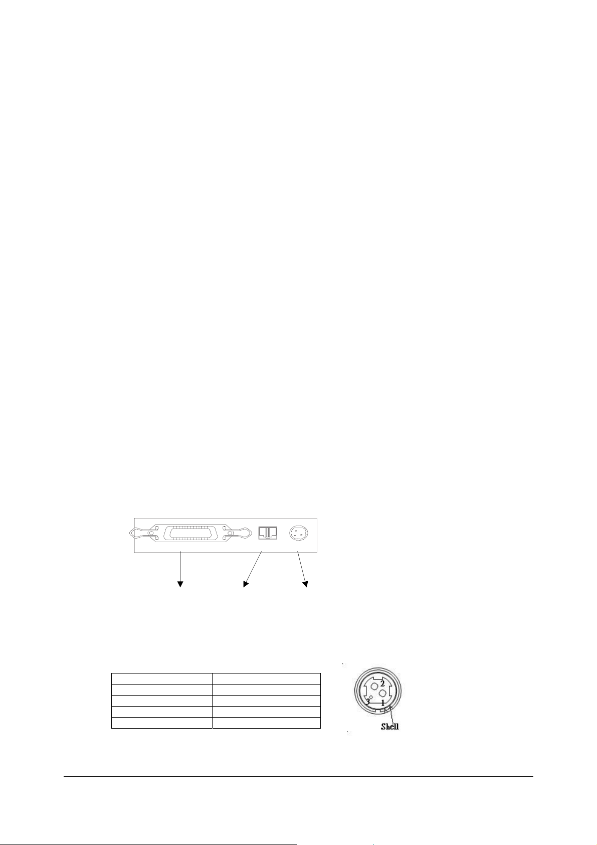
1.5 Buttons, Switches, and Panel Lights
Power Switch
Type:
Function:
Note:
Turn on the power only after co
Panel Button
FEED button:
Note:
The ESC c 5
di
sabl
ed the
comman
button, it
Rocker switch
T
he power switch turns the power
nnecting the power supply.
If you
push this button once
feeds pape
ESC
2
and
will feed paper co
Pa
per
feedin
performed when the
be
d en
ables or di
will not func
tion
r for one li
ESC 3
. If yo
nti
g using the F
sables the panel button. When
.
and
ne based
u hold on
nuou
sly.
EED
printer cover is open.
ializing
on or off.
the print
release it, t
on t
he li
ne spacing set b
the button
button canno
the command
er.
he printer
, the prin
t
ter
y
- 9 -
Page 12
Pane
l light
s
POWER:
ERROR:
PAPER:
TM200 Service Manual
Green
On: Power is on.
Off:
Red
On: O
Off:
Blinking:
Red
On:
Off:
Blinking
Power
is no
t on.
ffline (excep
using the FEED
state)
Normal condition.
Error
T
he pa
per
Pape
r is loaded
Sel
f-test
t during pape
button and the error
roll near
(norma
standb
y st
end is de
l condition)
ate
r feeding
tected.
Note:
The panel lights can tell you a lot of information about the situation of the printer,
please refer to
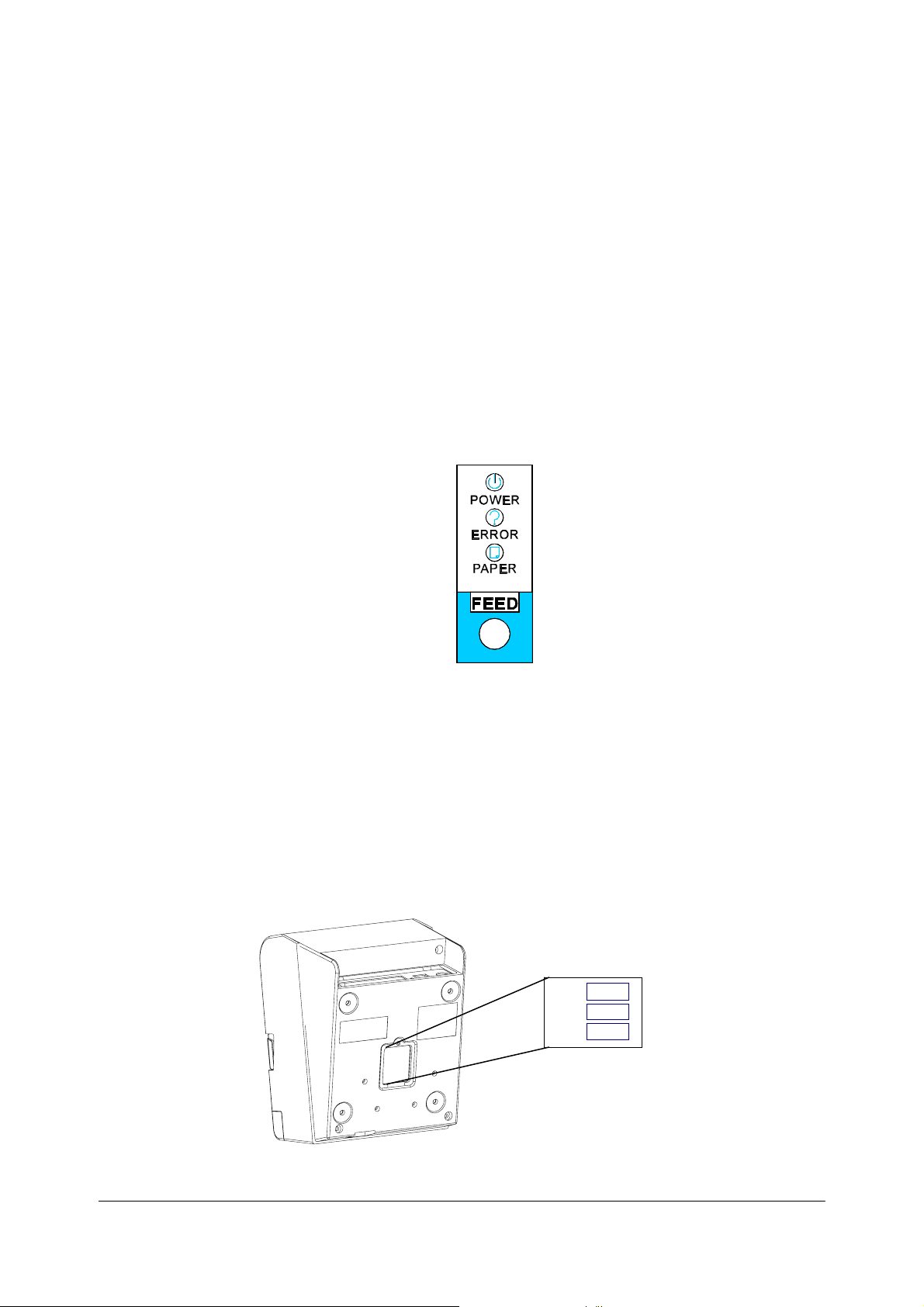
DIP Switche
s
Serial interface mode
T
he DI
P swit
ches are loca
Fi
gure 1-4 P
Appendix C
l
ted
at
Fi
gure 1-5
anel
butto
for details.
the bottom of
DIP switches
n and
the case.
SW3
SW2
SW1
indicators
- 10 -
Page 13
TM200 Service Manual
g
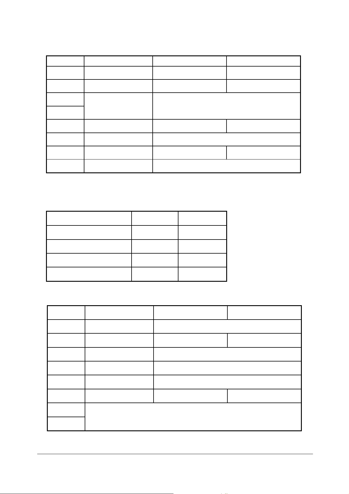
DIP switch 1
DIP switch
1-1 Print emulation TM200(default) EPSON Emulation
1-2 Paper near end sensor Vertical Horizontal(default)
1-3
1-4
1-5 Cutter setting Disable Enable(default)
1-6 Stop bit Fixed to OFF (1 bit)
1-7 Cutter mode Full Partial(default)
Function ON OFF
Selects print density Refer to the table as below
1-8
Reserved: do not change
settin
s
Fixed to OFF
Note:
TM200 accept ESC/POS command. Dip 1-1 for different printing format, ON(TM200)
for 48 characters per line, OFF(EPSON Emulation) for 42 Characters per line.
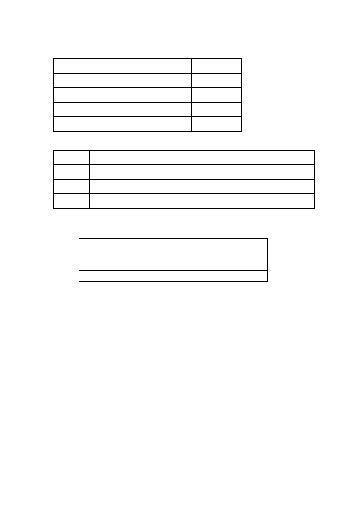
Print Density Selection
Print Density SW 1-3 SW 1-4
1 Low power consumption
mode
2 (Normal) OFF(default) OFF(default)
3 ON OFF
ON ON
4 (Dark) OFF ON
DIP switch 2
DIP switch
2-1 Reserved Reserved
Function ON OFF
2-2 Receive buffer capacity 2K bytes 96K bytes(default)
2-3 Handshaking Fixed to OFF
2-4 Data word length Fixed to OFF (8 bits)
2-5 Parity check Fixed to OFF (None)
2-6 Parity selection Even Odd(default)
2-7
Transmission speed (See the table below)
2-8
- 11 -
Page 14
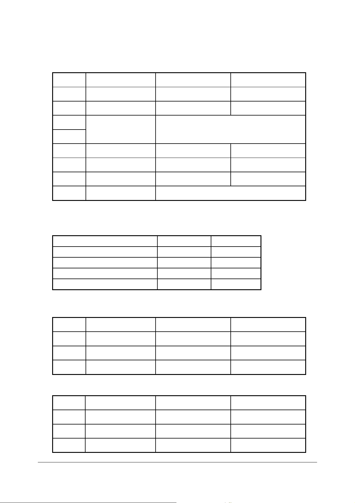
Transmission Speed
Transmission Speed
(BPS) – bits per second
4800 OFF ON
9600 ON OFF
19200 OFF(default) OFF(default)
38400 ON ON
DIP switch 3
SW 2-7 SW 2-8
TM200 Service Manual
DIP switch
3-1 Buzzer1 setting Disable Enable(default)
3-2 Buzzer 2 setting Disable Enable(default)
3-3 ~ 3-8 Undefined - -
Function ON OFF
Note:
In order to connect Serial port, the host setting should be set as:
Data bits 8 bits
Parity check None
Stop bits 1 bit
Flow control (suggest to set for None) None
- 12 -
Page 15
TM200 Service Manual
P
arallel interface model
DIP sw
itch 1
DIP sw
itch
Function ON OFF
1-1 Print emulation TM200(default) EPSON Emulation
1-2 Paper near end sensor Vertical Horizontal(default)
1-3
Selects print density Refer to page as below
1-4
1-5 Cutter setting Disable Enable(default)
1-6 Parallel port supports EPP SPP/EPP(default)
1-7 Cutter mode Full Partial(default)
1-8
Reserved: do not change
settings
Fixed to OFF
Note:
TM200 accept ESC/POS command. Dip 1-1 for different printing format, ON (TM200)
for 48 characters per line, OFF (
Print Density Selection
Print Density SW 1-3 SW 1-4
1 Low power consumption mode ON ON
2 (Normal) OFF(default) OFF(default)
3 ON OFF
4 (Dark) OFF ON
EPSON Emulation) for 42 Characters per line.
switch
DIP
DIP sw
2-1 Auto line feed Always enabled Always disabled(default)
2-2 Receive buffer capacity 2K bytes 96K bytes(default)
2
itch
Function ON OFF
2-3 ~ 2-8 Undefined - -
DIP sw
DIP sw
3-3 ~ 3-8 Undefined - -
itch
3
itch
Function ON OFF
3-1 Buzzer1 setting Disable Enable(default)
3-2 Buzzer 2 setting Disable Enable(default)
- 13 -
Page 16

TM200 Service Manual
1.6 Self-test
T
he pr
inter has a sel
Control circuit
Printer mechanisms
Prin
t quality
Control soft
DI
P switch
NOTE:
This test is independent of any other equipment or software.
Running the self test
1. Make sure the printer is turned off and the printer cover is closed properly.
2. Make sure a paper roll has been installed properly.
3. While holding down the FEED button, turn on the printer using the switch on the front
of the printer to begin the self test. The self test prints the printer settings, and then
prints the following, cuts the paper, and pauses.
4. Press the FEED button to continue printing. The printer prints a pattern using the
built-in character set.
5. The self test automatically ends and cuts the paper after printing the following.
Please re-start to exit SELF-TEST
f-test
function that checks the foll
functions
ware version
settings.
owing:
If you want to continue SELF-TEST
Please press the FEED button
*** completed ***
- 14 -
Page 17

1.7 Hexadecimal Dump
TM200 Service Manual
Hexadecim
al Dump Function
This function prints t
er
numb
s and in their corresponding characters.
he data tra
nsmitted from t
he host
computer
in hexadeci
Performing a Hexadecimal Dump
To use the hex dump feature, follow these steps:
1. After you make sure that the printer is off, open the cover.
2. Hold down the FEED button while you turn on the printer.
3. Close the cover.
4. Run any software program that sends data to the printer. The printer prints
“Hexadecimal Dump” and then all the codes it receives in a two-column format.
The first column contains the hexadecimal codes and the second column gives
the ASCII characters that correspond to the codes.
Hexadecimal Dump
1B 21 00 1B 26 02 40 40 ← ! ← & ☻ @ @
1B 25 01 1B 63 34 00 1B ←%☺← c 4 ←
41 42 43 44 45 43 47 48 ABCDEFGH
5. Close the cover and turn off the printer or reset it to turn off the hex dump
mode. (or to terminate hex dump, press FEED button three times, and
when you see
the hex dump mode was turned off.
*** completed ***
Note:
In
suf
fic
ient prin
Ending hexadecimal dumping
Hexadecimal dumping end
e interface
th
after printing ha
t da
ta to
fil
l th
e la
st li
s by turnin
s finished.
ne can be printed by
g the power o
ff or resetting the printer via
setting
th
e prin
mal
ter offlin
e.
- 15 -
Page 18

1.8 Paper Sensors
T
he pr
inter has 2 paper
Pa
per roll near-end
T
he sensor detect
When the pa
near-end of the pa
Pape
r roll end
sensor
This sensor de
When t
he sensor detects
Note:
After instal
printing.
Cover Open
When t
cov
e
r is op
he cover
ened
Note:
Be sure to u
Do not open
Do not open
may
Cover Open
T
he cover open sensor monitors the printer
during printi
vers when t
reco
When t
inter
pr
ng, t
he sensor detects
goes offl
Note:
Whether the cover is open
sensor.
ling n
Button
open button (located to the
. When th
se the co
the co
the co
be
da
maged.
Sensor
he
ERROR
he cover
ine. The
sensor
sensor
s a ne
per roll diameter becomes suffici
per roll and
tect
s whet
ew paper roll, close the printer cover; then th
s as follows:
ar-end
her pape
a pa
e cover is cl
ver open button
ver during printing.
ver during the auto
light
bl
is closed
a cover
printer r
.
open whil
ecovers when the cover is closed
or not
of a paper roll.
the PAPER indicato
r is pr
esent or not.
per-end, t
osed, the cover op
inks and the printe
does not affect the status
he printer
ri
ght
of the
to op
en the printer cover.
cutter is
cover. W
e th
e pr
operating; oth
hen the sensor detects a cover open
inter is in the standby
TM200 Service Manual
ently small, the sensor detects a
r lights on.
stop
s pr
cover) is pr
en butt
r stops printi
reported by the paper roll end
inting.
e printer restarts
essed, the printer
on is la
tched
erw
ise the mechanism
ng. T
he printer
status, the
.
.
1.9 Standard Accessories
Sample paper roll
User
Exclusive extern
Disc x 1
Communication printer cable
's Manual
x
1 roll
al power supply uni
- 16 -
t and power cord
Page 19

1.10 Options
1.11
Standard cable cover set (included wall mounting bracket)
Top waterproof cover
Consumables
TM200 Service Manual
Specified p
Specified
Packaged roll paper
Note:
The foll
Original paper:
Note:
Do not use any paper other than these specified above. Oth
reliab
aper
paper
owing
ili
ty and print
Roll pa
Original paper: TF50KS-E Nip
Co.,
Original paper: PD
In Japa
In North Amer
In Europe: Nakagawa Mfg. (Europe) GmbH
In Sout
paper can be used in
AF50KS-E
P3
50 (F3
U
.S.A.)
(
PD
190R
quality are affected ad
per: NT
Ltd.
n: Na
heast
stead of the specified paper above.
Oji
P080-80
kagawa, Seisak
ica: Na
Asia:
Jujo Thermal Oy (Finland)
80)
, P3
10 Kanzaki
Pape
versely.
pon
160R
Oji Pape
ujo
kagawa Mfg. (USA) Inc.
N.A.K. Mfg.
r Mfg.
(Mal
Specialty
Co. Ltd.
erw
ise, print head
Pape
r Industries
r Mfg.
aysi
a) SDN BHD
Papers, I
Co. Ltd.
nc.
1.12 External Power Supply Specifications
Inpu
t specif
Rated input voltage
Rated fr
H
A
Po
z Rate
Po
wer switch
wer LED
ications
equency
d inpu
t cu
rrent
90
to
264 VAC
50
/60 Hz ± 3
Less
than 100
None
None
- 17 -
V
Page 20

Output specificat
Output voltage
Rated outp
Rated outp
Output peak
ions
ut curr
ut power
ent
current
TM200 Service Manual
24
VDC ± 5%
2.5 A
Approxi
4.
5 A (within 300 ms duty 1/6)
mately 60 W
- 18 -
Page 21

2 Mechanisms and Operation
2.1 Component Connections
TM200 Service Manual
This printer
is made up
of t
he following major
TM200 prin
ter
mechanism (switch ci
I/
F ci
rcuit board
assembly
Main circui
t b
oar
d unit
2.2 TM200 Printer Mechanism
This printer
following
consists of three
illu
stration shows t
mechanisms:
he external co
compo
rcuit board assembly)
a prin
nfiguration of t
nents:
ter
mechanism
he TM200
and
a cu
tter module. The
.
Figu
re 2
.1 T
M200
external configur
ation
- 19 -
Page 22

Printer Mec
hanism
Thermal head Module
T
he thermal
act with t
cont
with the thermal head’
e
rfor
p
rinting
P
head
is desig
he plat
med when heat is generated by
is perf
ormed according to
1. T
he pr
int
signal
send
rr
co
espond
to each dot t
2. Resist
3. T
ors at ea
he heat ener
h
rough the protective
t
f
the paper.
o
ch el
gy g
en. T
s heating
s a
ectrode
ener
ned
so it
he roll
pa
element at
pr
escribed ene
o be pr
generate heat
ated
by t
layer to t
s heating
per
the followin
inted.
he resistors is transmit
he pa
element is positioned
wrap
ped
ar
ound
a prescr
the
heating
rgizing pulse to t
.
per’s he
ibed
element
g steps:
at-sensitive layer, c
TM200 Service Manual
wher
th
e pl
aten is kept
pr
essure,
.
ted to the roll pa
he el
and
ect
rodes that
ausing co
e it
pr
comes i
in cont
inting
per
surfa
lorati
is
nto
act
ce
on
The paper outle
so
acc
o
t
rin
p
rin
p
t of the printer is c
me reason, ther
u
mulation
be 80mm or less). Th
t pit
ch becoming unev
ter
afte
e is en
of two or three normal
r t
he pa
per
Figure 2
ough ro
is reduces the chance of receipt paper be
en. Paper
outlet
.2 Frame cove
overed,
om in the sp
le
that ac
is opened.
r open
and even
ace between the pl
ngth
receipts (the leng
cumula
if paper output become
tes can be easily pulled
- 20 -
aten
and
th of
one sheet
coming be
s blocked for
fr
ame cover
is a
nt and of t
ou
t of t
for
ssumed
he
he
Page 23

Au
toc
utter
Module
This printer
nd a
a
T
he autocutte
a
per. It is a
p
oll
paper thr
r
ationa
st
to
fixed
Autocutter op
T
he frame cover
sing
Clo
wit
h th
r
oug
b
Cutter blade knob
T
he movabl
f
ormed. In addition
per
frame co
sition
po
is equipped
manu
ry blade to separate completely from the moving blade. T
the fr
eration
the frame cover causes t
e paper cutter
ht i
nto
e blad
ver
cannot be opened
.
wi
th an aut
al cutter fo
r ha
separate
ough an autocutt
ame cover,
can be closed
relative position.
r manu
s two opposing
cutter blade-ty
whil
frame, and the stationary blade and
e is in the ho
to safety
ocut
ter
module
al cutt
ing.
cutter blades that
pe mecha
er mech
e the
while the movable blade is in t
me position whenev
or close
anism slit. Op
moving
he st
consid
blad
ationary blade to come in
erations, this enables a mech
d while
for cutting
operat
nism that do
e is attached to
er cutt
the movable blad
e like
es not re
ening
the
movable blad
er operation is not bein
TM200 Service Manual
of t
he roll paper
a sci
ssors to cu
quire p
frame cover causes t
he stationary blad
th
e main fr
he home po
to partial cont
e are
anism in whi
e is no
t in t
t t
assage of t
ame.
sition
.
act
g
he home
he
he
e is
ch th
he
e
2.3 Main Circuit Board Unit
The main
CPU and CPU
T
Con
Drawer
Po
Filter circuit
circui
CPU
RAM
ROM
te array
Ga
Reset ci
M200 co
T
Pa
Autocu
Detect
+24V out
+5V output
rcuit
ntrol circui
hermal
head drive circuit
per
feed
motor driv
tte
r drive circui
or circuits
trol panel
kick
wer supply circ
s
put
circuit
t board
perip
cont
rol
control
uits
ci
rcuit
unit is made up of t
heral logic ci
ts
e ci
rcuit
t
ci
rcuits
circuit
rcuits
he following
electrical ci
rcuits:
- 21 -
Page 24

CPU
perip
heral logic ci
RA
M (128K byte)
RAM is used for tempor
Data receive
Pattern data pr
Da
Flash memo
RS-
232C
ta used for
ry (2M or 8M
A printer
The
performed
sub
control program and cha
co
ntrol pro
in accord
-
memory for
interface specifications
Sel
ect
ion betw
TM200
Co
ntrol Circuit
Thermal head driver
T
he pr
int
head
ots
per line. Al
d
the
print
head, and send
sign
CLOCK
co
STROBE2, while energizing time
#
Changes in head
ther
nfir
mist
al, to t
med
by latch signal #LATCH
or built into the
Paper feed moto
T
he pa
per
gizing direction switching
ener
ial-purpose IC controls the paper feed motor in
spec
using Q1, Q2, Q3, an
r dr
feed
Autocutter drive
T
he autocut
r circuit
ter driver use MOSFET
De
tector
Pa
per end se
circuits
T
he thermal
cted via switch circui
conne
d sign
en
nsor ci
pr
al
FP_Sensor is in
Cover open se
nsor circuit
rcuits
ary
storage of
d fr
om the interface (receive buffer)
inted by
CPU r
gram
such it
the print
out
ines (flags, pointers, et
bits)
controls basic printer
ance wit
h th
ems as expanding
th
head
racter
is prog
e foll
generator data is
ram. Another
een two si
gnal
s (pin 6 (DSR) or
circuit
of t
l pri
he driver
temp
iver circ
motor
rcuit
inter mecha
he r
eceipt printe
nt hea
d control is performed via a gate array. A
ing
of print si
sets the pr
erature causes fl
hea
d, which is outp
uit
is co
nstant
d Q4 signals.
nism is
t board a
put to th
r mechanism is a
gnal
int/non-print st
. Pr
int ti
is controlled by
uctuation of t
-current d
signals (PH1,PH2,PH3
to control DC motor.
equi
ssembly to
e DSP’s port.
owing:
unit (printer buffer)
op
erations, and
charact
pi
DATA-IN, wh
me con
ut as temperature signal
riv
en by a
pped
c.)
written into flash memory.
all CPU cont
flash memory
er g
enerator da
n 25
(INI
T)) is possible.
ther
mal typ
ich is sync
atus of each dot.
trol is performed by #
the gate array.
he resistan
special-pur
and
PH
4) fr
accordance with these signals
wi
th a
paper end
the ma
in circuit
TM200 Service Manual
rol
is
works as a
ta.
e print hea
driver is built
hronized
Data
STROBE
ce valu
board unit
e of th
THERMISTOR.
pose I
C. Th
om the CPU
sensor, whi
d with
into
with t
he
is
1 and
e
e
. T
he
ch is
. The paper
576
- 22 -
Page 25

T
he cover open sensor is lo
connected via Door Sensor board
nal
sig
INPUT_4
is inpu
Control Pan
This co
PAPER
wer circ
po
Drawer Kick
When si
ansi
tr
whi
ca
n be obtained
el Control Circuit
ntrol panel is
)
and one button (F
uit. The
ERROR
Control Circuit
gnals KICK_OUT_X1
stor array and
ch indicates whet
from t
located
outputting
Power Supp
ly Circuit
T
he tabl
Powe
+24V Co
T
he +24V power
split into 3.3V and 1.8V.
+5V Cont
A +5
The
T
he RS-2
nte
i
e as below
r supp
Voltage Value Main Applications
1.8V Power supply for the CPU core
3.3V Power supply for the CPU I/O pins
+5V (VCC)
+24V
ntrol Circuit
rol Circuit
V regu
switching regu
rface’s on
lator
32 power
shows sup
ly voltage values and applic
supply is split betw
circui
lator
supply is g
board
driver.
cated
t to t
he CPU.
on the mainboard
EED
). The POWER LE
and PAPER LEDs ar
and KICK_OUT_X2
the drawer driv
her or
not the draw
he host
interface.
ply voltage values and their applications.
Logic circuit power supply
Interface board power supply
Detector power supply
Thermal head logic circuit power supply
Printer mechanism power supply
Paper feed motor
Thermal head
Autocutter
Drawer kick driver power supply
t switc
hes the input +2
IC
swit
ches t
enerated
TM200 Service Manual
next
to
the therma
assembly to the main circuit board unit. Detector
. It ha
D drives
e con
e signal
er is op
en, is input to the CPU, and this stat
ations
een t
he pr
inter
4V po
he input
by
+24V, and +5V voltage is output.
a ch
arge up circui
l printer
s thr
ee LEDs (POWER,
when +5V is supplied by t
trolled by the CPU.
from CPU go active, it
. The OPEN_CLOSE signal,
mechanism, and
power
wer supply and conver
supply and +5V. Then
t built into t
he RS-232
it is
ERROR,
he
causes
us
ts it to +5V.
- 23 -
Page 26

2.4 I/F Circuit Board
This
printer uses a TM series univer
fferent in
di
terfaces by changing t
RS-
232 Interf
ace
I
EEE
1284
Interface
USB
Multi interface (Parallel and Serial)
Interf
ace
2.5 Switch Circuit Board
sal
inte
rface, which
he interface board.
allows support
TM200 Service Manual
of a variet
y of
Switch circui
Paper
LE
t board has
FEED button
D (
POWER, ERROR, PAPER)
the follo
wing
buil
t-in el
ectrica
l circuits:
- 24 -
Page 27

3 Handling, Maintenance, and Repairs
3.1 Handling
TM200 Service Manual
Transport Pr
ecautions
Take t
he following
tran
sporting it:
CAUTION:
We recommend that each unit
LABAU Technology Corp..
Remove the paper
Make
sure that the paper
Setup Precautions
Note:
The co
ver of the unit i
Operationa
l Precautions
Observing the following oper
CAUTION:
Conn
conne
Do
turning po
i
c
Never
During no
knob by
t
T
damaged. Never
obj
Never
hand
T
t
ect t
he interface cable, power
ctor
s of the unit.
not
tu
rn unit power
wer off whil
n
the cutt
over.
o
op
he heating
ects.
he head
ouch component
er blade being exposed, whic
pull out
rmal
hand. Doin
en the pa
touch the pr
. Do
ing
and mo
steps to protect
from the un
s sec
Do no
e a paper cu
paper whil
operat
per roll cover.
elemen
so ca
ion, never op
g so ca
t of t
al
low
these component
inter mechanism’
n soil the heating
tor
areas are very hot during and
s in these areas dir
th
e unit ag
be pa
it.
roll cover
ured in place with tape. Remove the ta
ationa
l preca
cable,
t use undue forc
off duri
e the paper roll cover is open.
he printer
ng normal
t op
en the cutter cover
n cause the cutter blade to be expo
mechanism’s thermal
s (ther
elemen
ectly with yo
ainst vibration and impact whenev
cked individual
is securely closed.
uti
ons prot
and dr
e when plugging cabl
op
eration is being performed. Doin
h w
ill make it
s to
come i
mal head’s) heating el
t and
ects
awer
cable to t
eration. Be especially
impossi
and
nto
cont
affect
proper op
immediat
ur hand.
ly in th
e boxes suppl
pe before using the unit.
the unit
head
against dama
he applicable
es in
to connect
careful to avoid
g so can result
ble to open the paper roll
rotate
the cutt
sed, maki
and the d
act with metal
ement with your
eration.
ely
after
er man
ng it impossibl
river IC ar
or
pr
inting
er
ied b
ge.
ors.
ual
e easi
ot
her ha
. Do not
y
e
ly
rd
- 25 -
Page 28

Paper Prec
autions
CAUTION:
Be
of
o
T
t
hermal
pap
Take t
in
Do no
sure to
this man
p
eration of the thermal
hermal
pa
pa
er
to color
he paper roll out
a high temper
t use
Loading paper ro
Note:
Be sure to use
a
per
glued
p
Make sure that the printer
1.
Open t
2.
he pa
per
use only pape
ual
. Ther
per
star
per
against
and
ature and
this
unit to prin
r that conforms
mal paper that includes Na, K, or
head’s
ts t
o color at
the effects of he
charact
of t
heating
around 70°C. Take care
ers on the paper to fade.
he pr
inter when yo
humidity
t on label
with
the sp
element.
at, li
ght, and
u will not
environment.
paper.
ll
paper rolls
that meet the specifications. Do not u
to the core because the printer cannot detect th
roll
cover by pressi
is not r
eceivi
ng data; ot
ng t
he cover-open button.
herwise, data may be lost.
TM200 Service Manual
ecifi
cations in t
C1 io
ns can affect
to protect
humidity, which can ca
use t
e paper en
he precedin
proper
unused and prin
he pr
inter fo
se pap
r a long
er rolls that have the
d correctly.
g sect
use t
he
ti
ion
ted
me
Remove the used pape
3.
r roll core if
ther
e is o
- 26 -
ne.
Page 29

Insert the
4.
5. Be sure to
paper roll as s
note
the corr
hown.
ect direction that t
he pa
per
comes off the ro
TM200 Service Manual
ll.
6. Pull out
a smal
l amo
unt
of paper,
as shown. Then close t
he cove
r
- 27 -
Page 30

p
3.2 Problem Solving
TM200 Service Manual
Errors
See Chapter 4,
Paper roll cover does not ope
1. Turn the printer off and press the cover open button to open the cover.
2. Remove the jammed paper and put the roll back in the printer and close the cover.
(Take care not to touch the print head.)
3. If paper is caught in the automatic cutter and the printer cover cannot be opened,
open the cutter cover as shown below.
4. Then turn the knob until you see cutter blade back to the lowest position, as
shown in the illustration below. This returns the cutter blade to the normal
position. Also notice that there is a label near the cutter to assist you.
Error Types and Processing.
n (
When paper
jams, turn the
knob until the
cutter blade back
to lower
osition.
paper ro
ll cover button does not work)
5. Close the cutter cover.
6. Open the printer cover.
7. Remove the jammed paper.
Note:
Other than a
ect
such as a push pin or paper clip. If
obj
ri
bed above to return the cutter to its normal posi
desc
paper jam, the autocutter lockin
Do
not op
en the cutter cov
er unless yo
- 28 -
g up could have b
this is the case, follow the same
tion
.
u find
that the paper roll cov
een
ca
used by
er does not open.
a foreign
proced
ure
Page 31

3.3 Clearing Paper Jams
TM200 Service Manual
CAUTION:
Take care no
n damage th
ca
Do not
ho
t.
1. Op
en t
2. Next,
3. Grasp the lead
4. Correct
t to
let metal objects co
e head.
touch t
he pa
he thermal
per
roll
cover.
Note:
See th
e previous section
turn power o
ing
ff.
end
of th
Note:
Be sure to remov
malfunc
to
the problem
e all of
tion
.
that caused the paper jam and reload the pape
Note:
See the section “Loadin
me into c
head
or radiation plat
for steps to take if
e receipt paper
the paper. Leaving part of the pa
g pap
er roll” for details on
and
ontact with
e. Pr
inting
the paper roll cover does not open.
pull the jammed paper.
how to load
the thermal
can cause t
hem to beco
per in the unit can
r roll into the unit
paper roll.
he
ad. Me
me very
cau
se the sensor
tal
.
- 29 -
Page 32

Maintenanc
Setup
Paper particles,
p
aper
fo
reign m
Dirt
sid
in
components
Springs
Operation
Cleaning
Therma
Caution:
3.4 Inspection and Maintenance
Pr
oper performa
e
s it po
mak
it
which
is desi
e Procedures
The insp
n
spect
i
asis, and
b
have a more detailed te
scra
, lint, an
e
ps,
atter
d dust
ect
ion, whi
l head
Turn off the
Note that th
hot during
about 10
printer power before cleaning.
normal operation, creating
minutes afte
nce of t
ssible for this unit
he inspection and
to
perform for
maint
gned.
ion pro
periodic inspection, whi
Inspection item
Check for proper connection of cables.
Check for proper insta
Make sure the paper roll
cu
Open the paper ro
sure
or other foreign matter present.
Check for dirt, lint, and dust in th
path.
Ch
surface of or in the paper end sensor.
Ch
white with
Check the frame
other spring
disc
Check for ab
operation an
cedur
es descri
ch ca
n be
performed
chnical knowle
tt
er cover are closed.
ll co
there are no larg
eck for any fore
eck if the platen
paper particles.
onnection.
ign matter on th
roller has becom
shutter spring and all
s fo
r d
efo
nor
mal noise duri
d any ab
bed
he
re ar
by
the individ
ch should be
dge
of
llation of
ver and ma
e pieces of paper
rmation an
nor
co
mal
pa
ver and
e pape
d
ng
printing.
e therma
l head (the
rmal
elemen
the danger of burn injury.
r turning printer
po
wer
the year
e divided between two types: daily
the
per roll.
ke
e
e
t an
of
TM200 Service Manual
enanc
e pr
oced
ures described below
s of tr
ouble-fr
ual
s who use the
performed by
unit.
Action
Reconnect any cables that have
o
me loos
c
Correctly
Clos
e all covers.
Clean out any paper or foreign
matter.
r
Use a
vacuu
move all dirt,
re
Wipe away fo
or some other so
Wipe o
moistened with water.
If you discover
in
new one.
Co
wit
Chap
ff t
stall the sp
rrect any problems in acco
h the
ter 4.
d radiation
ee op
unit on a dail
individuals who
e.
insta
ll pa
per ro
m cleaner to
lint, and dust
reign m
ft material.
he roller with a cotton swa
a problem, correctly
ring or
replace it
Troubleshooting Guide in
plate)
becomes very
Be sure to wait fo
f before b
eginning
th
eration for
y
ll.
completely
.
att
er with paper
with a
rdance
e cleaning.
b
r
- 30 -
Page 33

1.
2. Clean t
Caution:
Never
ther
3.
Afte
Platen
ro
Wipe t
he pl
t
Paper
roll
Cl
ean the pa
Exterior dirt
Use a clea
uni
wa
Caution:
Do not use al
agen
mage to plastic and
da
Dirt,
lint, dust
Use a vacuum cl
Op
en t
he pa
per
roll
cover.
he t
hermal
t
hermal
IPA).
mal element.
head
touch the ther
r confirmi
ller on
receipt side
he platen
aten roller gear.
en
d sensor on receipt side
per roll end sensor with
elemen
wi
th a
ng that t
roller
surface with a cotton
t (the area that l
cotton swab
Head Thermal element
mal elemen
he alcoho
moistened with
Radiation plate
t with your hand.
l solven
a cotton swab moist
n, dry
t clean, wipe with a cloth moistened
ter
and
a mild
ts for cl
clot
neutral de
cohol,
eaning.
eaner
h to wi
benzene, thinner, trychl
pe off dirt fr
tergent
Such
agen
rubbe
to
completely remove al
.
ts can
r components.
ooks li
ke it
is marked
an alcoho
Doing
t has dried up
swab moistened
om the
exterior
wi
th a small amount
oroethylene, ketone or other si
cause deformation, deterior
l dirt, lin
comp
ened with a little
of the unit. If this does not
t, and dust.
with a thin bl
l solvent (ethanol
so can
with a little wate
damage the
letely
, cl
of water or a
TM200 Service Manual
ack
li
ne) of t
, meth
ose the paper roll cover.
r while ro
water.
ation, an
get the
solution of
milar
d
anol
tatin
he
, or
g
- 31 -
Page 34

4 Troubleshooting
4.1 Symptoms and Solutions
TM200 Service Manual
This explains how
“Ch
eckpo
e
termi
d
Table 4-
Symp
Power does
Power
c
ompleted
Or, POWER
There are missing dots
in
th
The print is thin.
Unevenness occurs in
the concentratio
the
print.
Pape
Paper jams
Missing ch
characte
ERRO
ne the cause of th
1 Symptoms and checkp
tom
on self chec
LED
e print
r feed failure.
aracters/misprinted
rs/fon
R LED is lit.
ints” co
not turn on
lumn indicate t
k is no
does
not light.
n of
t breakdown.
to find
.
t
Receipt
pr
inting
Receipt
p
rinting
Receipt
pr
inting
Th
ermal
printer
the source of a problem using
he order to
e pr
oblem after ch
use to check
ecking t
he first item, pro
oints
Checkpoints (by Priority)
1. Check the power supply unit.
the po
wer supply
2. Check the main circuit board unit.
3.
Unplug the printer. Then
nn
ector
co
bac
coil has burned out and
4.
Replace the I/F circuit
1. Clean the thermal print head. (See page
2.
Replace the t
Replace the main
3.
1. Clean the thermal print
2. Adju
switches). (See page 12
3.
Replace the t
4.
Replace the main circ
1. Clean the thermal print head. (See page
2.
Replace the t
3.
Replace the main
1. Check that the roll paper
2.
Check the rece
3.
Replace the main
Rem
ove
“Clearing Paper Jams.”
1. Check the DIP switch settin
2. Replace t
1.
Close the cove
2. Install a new pape
from the main board
k
in
, and po
st DIP
the
wer it on
hermal print head module. (See page 44
swit
ches DSW 1-3 and 1-4 (print density sele
hermal print head module. (S
hermal print head module. (S
ipt paper feed motor.
jammed
he interface cable. (See page 47)
r.
the symptom. The numbers in the
the problem. If
Check that 24V is coming out
unplug each moto
. This will let you
is pulling down the po
board.
circ
uit board unit. (See page 47
head. (See page
uit bo
circ
uit board. (See page 47
circ
uit board. (See page 44)
paper by followin
r roll.
on
)
ard unit. (See
is prop
gs.
you cannot
ceed to t
e by o
ne; plug the printer
know if any moto
erly
loaded.
g the directio
he next
r or coil's
wer.
30
)
30)
ee page
page 47
30
)
ee page
)
ns in
number.
r or
)
)
ction
44
)
)
44
)
of
- 32 -
Page 35

4.2 Error Types and Processing
Printer Operatio
T
he pr
inter exec
St
ops all pr
Flashes the ER
Data Receive E
If one of
the followin
Parity error
Framing error
Overrun e
n when an Error Occurs
utes
the follo
inter oper
ROR LED.
rro
r (only with the se
g errors occu
rror
wing
ations.
op
erations upon det
rial interface model)
rs during serial inte
TM200 Service Manual
ect
ing
an er
ror.
rface communications, the printer ig
nores the data
- 33 -
Page 36

Lo
cations of the Main Elements on the
T
he following shows the locations of the main element
CPU (U1)
Autocutter drive
(J5~J8)
Thermal Head
power MOS
(Q14, Q15)
Ma
in Circuit
s on t
he main ci
Board Unit
rcuit bo
ard
TM200 Service Manual
unit.
ROM (U10, Low
byte)
ROM (U12, High
byte)
Paper feed motor
driver (U31)
- 34 -
Page 37

TM200 Service Manual
5 Disassembly, Assembly, and Adjustment
5.1 Before Starting disassembly, assembly, and adjustment
Be
sure to observe the followin
just
ment.
ad
Caution:
Disc
onnect the power
continues to flow through i
turned off.
dama
Perfor
ge to the pri
Disconnect
Perform al
di
sassemb
Neve
r touch an FPC
co
nnect
all
l disa
ly can cause seriou
ors can result in improper connection.
g important points whenever performing disassembly
supply unit
nternal
ming work with
nter.
peripherals connec
ssembly in
accordan
or its co
from the printer before begi
circuitr
out disconnecting the power
ted to th
s dama
nnect
ors with
y ev
en when
e printer
ce with the proc
ge to the printer.
your
fingers. Getting dirt on the FP
before beginning work.
edures in this manual. Incorrect
the printer’s po
, a
ssembly, or
nning work. Current
wer
switch
supply can ca
use serious
C or its
is
5.2 Using this Manual
This section explai
Titles
T
he titles that appear
ajor part
m
s and blocks.
Disassembl
T
he pr
performe
Disassembly of some parts and
ocedures described
pr
y, Assembly, and Adjustment Procedures
oced
ures
d fr
Perform
the procedures in this manual in revers
ns a number of general conv
inside the sections of this manual descri
No
in this man
om beginning
in this manual.
t all of the part
ual
are
arranged so the entir
to end.
bl
ocks may
entions used in
s (se
rvice part
be impo
e to
this manual.
be the assembly and di
s) are
indicated
as titles.
e printer
ssible unless perfor
assemble the printer.
is disassembled when
med in
sassembly of
ac
cord
ance with t
he
- 35 -
Page 38

5.3 TM200 Disassembly , Assembly, and Adjustment
TM200 Service Manual
There are 5 block of TM200 showing as following,
Door sensor block
Paper out sensor block and paper sensor block
Autocutter module
Thermal head module
Main circuit board
Please following the steps for d
isassembly,
- 36 -
Page 39

Door sensor block
1. Loose 4 screws beside the thermal cover and move them.
TM200 Service Manual
2. Screwing 4 screws (the place indicated by the red circle on the photo) on the bottom of the unit.
3. Reverse the printer, move the body cover apart.
Note:
You may use your thumb push down the lever while the other fingers forcing up the body
cover.
- 37 -
Page 40

4. Open the up cover.
5. Move the 2 screws are circled indicated on the photo.
TM200 Service Manual
To install, reverse t
he removal pr
ocedures.
- 38 -
Page 41

TM200 Service Manual
Paper out sensor block and paper sensor block:
1. Loose 4 screws beside the thermal cover and move them.
2. Screwing 4 screws (the place indicated by the red circle on the photo) on the bottom of the unit.
3. Reverse the printer, take the body cover apart.
Note:
You may use your thumb push down the lever while the other fingers forcing up the body
cover.
- 39 -
Page 42

TM200 Service Manual
4. Remove the screws on the bottom of the printer mechanism.
5. Remove 2 screws circled on the photo and all the connections between printer mechanism and main
circuit board. Then, you can depart printer mechanism from its main board.
- 40 -
Page 43

TM200 Service Manual
6. Paper sensor connecter beside the printer mechanism as the photo.
7. Remove the screw on the bottom of the printer mechanism as circled on photo, the paper out sensor
could be moved then.
To install, reverse t
he removal pr
ocedure.
- 41 -
Page 44

TM200 Service Manual
Autocutter module:
1. Loose 4 screws beside the thermal cover and move them.
2. Screwing 4 screws (the place indicated by the red circle on the photo) on the bottom of the unit.
3. Reverse the printer, take the body cover apart.
Note:
You may use your thumb push down the lever while the other fingers forcing up the body
cover.
- 42 -
Page 45

4. Remove the 2 screws beside the autocutter and the connections from circuit board.
o
install, reverse t
T
he removal pr
ocedure.
CAUTION :
When you installed the autocutter module, you must foll
foll
ow th
em, it could cause an autocutter operation failure.
ow th
e steps below. If yo
(1) Secure th
e ri
ght
side screw.
(2)
Secure th
e left
side screw.
TM200 Service Manual
u do not
- 43 -
Page 46

TM200 Service Manual
Thermal head module
1. Loose 4 screws beside the thermal cover and move them.
2. Screwing 4 screws (the place indicated by the red circle on the photo) on the bottom of the unit.
3. Reverse the printer, take the body cover apart.
Note:
You may use your thumb push down the lever while the other fingers forcing up the body
cover.
- 44 -
Page 47

TM200 Service Manual
4. Remove the 2 screws beside the autocutter and the connections from circuit board.
5. Stretch your forefinger to the bottom of the thermal head module and force up to depart it from the
printer mechanism.
6. Remove the connections from circuit board.
o
install, reverse t
T
he removal pr
ocedure.
- 45 -
Page 48

CAUTION:
Note that the (thermal
danger
before beginnin
of burn inju
g the pr
head) becomes very hot during
ry. Be
sure to wait fo
ocedures.
When perf
measures to pr
e (thermal he
th
orming proc
otec
t against el
ad).
edures, be sure to use a gr
ectr
ostatic
Never
touch the ther
of the (the
rmal head) with
mal elemen
your hand.
t (the ar
Doing
Whenever th
otton
c
swab mois
ere is dirt or an
ten
ed with
y other foreign matter on the (thermal hea
alcoh
ol.
When you installed the autocutter module, you must foll
foll
ow th
em, it could cause an autocutter operation failure.
(1)
(2)
Secure th
Secure th
e ri
ght
e left
side screw.
side screw.
r about
charge.
ea th
at looks li
so can
normal operation,
10 minutes after tu
oun
ded wris
Failur
e to do so can re
ke it is marked with a thi
damage the heatin
ow th
t band
e steps below. If you do not
TM200 Service Manual
creating th
rning printer power of
or ta
ke other
sult
in
damage to
n black line)
g element.
d), clean it
off
wi
th
a
e
f
- 46 -
Page 49

TM200 Service Manual
Main circuit board
1. Loose 4 screws beside the thermal cover and move them.
2. Screwing 4 screws (the place indicated by the red circle on the photo) on the bottom of the unit.
3. Reverse the printer, take the body cover apart.
Note:
You may use your thumb push down the lever while the other fingers forcing up the body
cover.
- 47 -
Page 50

TM200 Service Manual
4. Remove the screws on the bottom of the printer mechanism.
5. Remove 2 screws circled on the photo and all the connections between printer mechanism and main
circuit board. Then, you can depart printer mechanism from its main board.
- 48 -
Page 51

TM200 Service Manual
6. Remove the two screws on the circuit board, you could depart it then.
7. Reverse the board, you could find the ROMs.
To install, reverse t
he removal pr
ocedures.
Caution:
When performing this proc
measures to pr
Internal circuit boar
cooled sufficiently be
There are 2 ROMs on the board, the one is LOW bye(U10), the other one is HIGH byte(U12),
please make sure the ROM be placed to the correct place.
Af
ter removing
har
ge dama
c
otect against electrostati
d components become hot during normal
th
ese circ
ge by pl
edures, be sure to use a
fore perfor
uit boards,
acing them in an an
ming this
be sure to protect th
c charge.
pr
ocedure.
ti-stati
gr
oun
c bag.
ded wrist band and
use.
Make sure they have
em against electros
take
tatic
other
- 49 -
Page 52

Appendix A Interface
I
EEE
12
84 Bidirectiona
Specifications
Data transmi
ssion:
Sy
nchroniz
ation:
Handshaking:
Signal
leve
ls:
Reverse communi
Switching b
T
he pr
in either of the followings:
1.
When t
etween online and offline
inter
is not
he po
nitialized by
i
cation (Pri
equipped with any onli
wer is tu
the reset
2. During t
he self-t
est.
3. W
hen t
he cover is op
4. Durin
5. W
g paper feed
hen t
he pr
detected by
lt
du
ha
e to paper shortage en
ing
inter stops
ei
ther
the paper roll
6. Durin
g macr
o executing st
7. W
hen a temporary abnormality occu
8. W
hen an error ha
s occu
l Parallel Interface
8
-bit Parallel
Externally su
P-/Ack
TTL compatible
nter
rned on
signal from
en.
using th
printing due to
andby
rred.
pplied P-/STROBE
and
P-BUSY
Host
): Nibble or Byte Mode
signals
ne/offl
or
until the printer b
the interface.
e paper feed butt
a pa
end de
abled
stat
tector or the paper roll near
by
ESC c
us.
rs in the power
ine switch
ecomes
on.
per-end (i
4
).
si
gnals
. Th
e pr
inter is pl
ready
for data tr
n cases when empty
-end det
sup
ply voltage.
TM200 Service Manual
aced into offli
ansmissi
pa
per
supply is
ector wi
ne status
on after it
th a printing
is
- 50 -
Page 53

Interface Pi
n Assignments
Pin Pin Name Pin Description and Function
1 P-/STROBE Data Strobe
2 PRINTER_D0 Data Bit 0
3 PRINTER_D1 Data Bit 1
4 PRINTER_D2 Data Bit 2
5 PRINTER_D3 Data Bit 3
6 PRINTER_D4 Data Bit 4
7 PRINTER_D5 Data Bit 5
8 PRINTER_D6 Data Bit 6
9 PRINTER_D7 Data Bit 7
10 P-/ACK Acknowledge receipt of Data
11 P-BUSY Strobe received, Waiting on Acknowledge
12 P-PE Paper Out / Paper Error
13 P-SELECT Daisy-Chain Device Select Signal
14 P-/AF Auto-Feed paper
15 NC*
16 GND GND
17 GND GND
18 NC
19~30 GND GND
31 P-/INIT Cancel Current Job (May be called /PRIME)
32 P-/ERROR
33 GND
36 P-/SEL IN Select In; Taking low or high sets printer on line or off
line
* NC: Not Connected
TM200 Service Manual
- 51 -
Page 54

Appendix B Exploded diagram
TM200 Service Manual
52
Page 55

TM200 Service Manual
Appendix C Panel lights and indicators
Indication LED light Panel status
Normal operation status z Power - Green
z Error - OFF
z Paper - Green
Upper cover is open z Power - Green
z Error - Red light
blinking
z Paper - Green
Paper end, or sensor can’t
detect paper roll
Paper near end z Power - Green
z Power - Green
z Error - OFF
z Paper - Red and
Green light blinking
z Error - OFF
z Paper - Red
Upper cover is open, or
sensor cannot detect
paper roll
Autocutter doesn’t work z Power - Green
Paper jam z Power - Green
z Power - Green
z Error - Red blinking
z Paper - Red and
Green blinking
z Error - Red
z Paper - Green
z Error - Red blinking
z Paper - Green
- 53 -
Page 56

Indication LED lights Panel status
Enter ISP mode (DIP
switch 1-8 on)
The printer was ready for
receiving data from the host
(after press FEED button)
Ready for ISP z Power - Green
z Power - Green
z Error - OFF
z Paper - OFF
z Power - Green
z Error - Red
z Paper - OFF
z Error - Red
z Paper - Red
TM200 Service Manual
ISP is finished z Power - Green light
blinking
z Error - Red light
blinking
z Paper - Red light
blinking
- 54 -
Page 57

Appendix D Parts number list
Item Part Number Descriptions
1 BK04001M TM200 Mainboard
2 BK04002D3 Parallel port interface board
3 CB00033A Parallel printer cable, white color, 36 pin
4 CB00033B Parallel printer cable, black color, 36 pin
5 BK04009F1 Serial (RS232 32K buffer) port interface board
6 CB04008D Serial printer cable, white color, 9 to 25 pin
7 CB04008E Serial printer cable, black color, 9 to 25 pin
8 BK04008C1 USB port interface board
9 CB04011A USB printer cable, white color,
10 CB04011B USB printer cable, black color
11 BK04010B3 Multi port(Parallel & RS232) interface board
12 CB04012A Parallel printer cable, white color, 25 pin
13 CB04012B Parallel printer cable, black color, 25 pin
14 CB04013A Serial printer cable, white color, 25 to 25 pin
15 CB04013B Serial printer cable, black color, 25 to 25 pin
16 BK04201A Thermal head module
17 BK04208A Autocutter module
18 BK04006C Door sensor
19 BK04005B Paper out sensor
20 BK04004C Paper sensor (Horizontal)
21 BK04004D Paper sensor (Vertical)
22 PW00003A Switching power, without power cord
23 CB00030A Power cord, 110V, US plug
24 CB00031A Power cord, 220V, European plug
25 CB00032A Power cord, 230V, Australia plug
TM200 Service Manual
- 55 -
 Loading...