

Page 1
®
Service Manual
Service Manual
Service ManualService Manual
B0 Wide-Format Professional Inkjet Printer
EPSONStylusPro9000
SEIJ98008
Page 2

EPSON Stylus Pro 9000 Revision B
NOTE:
The contents of this book may change at anytime without notice.
No patent liability is assumed with respect to the use of information contained herein.
SEIKO EPSON CORPORATION assumes no liability for problems or damages resulting from the use of the information contained
herein.
EPSON is a registered trademark of SEIKO EPSON CORPORATION.
Other product names used herein are for identification purposes only and may be trademarks of their respective owners. EPSON
disclaims any and all rights in those marks.
Copyright 1999 SEIKO EPSON C ORPORATION.
2
Page 3
EPSON Stylus Pro 9000 Revision B
PRECAUTIONS
There are cautionary notes throughout the text to help you avoid personal injury or equipment damage.
W ARNING
Signals a precaution which, if ignored, could result
in serious or fatal personal injury. Great caution
should be exercised in performing procedures
preceded by a WARNING heading.
Always observe the measures listed below when performing repair or maintenance procedures.
CAUTION
Signals a precaution which, if ignored, could result
in damage to equipment.
WARNING
1. Always disconnect the product from both the power source and host computer before performing any maintenance or repair procedure.
2. No work should be performed on the unit by persons unfamiliar with basic safety measures dictated for all electronics technicians in their line of
work.
3. In performing testing described in this manual, do not connect the unit to a power source until instructed to do so. When the power supply cable
must be connected, use extreme caution in working on the power supply and other electronic components.
CAUTION
1. Repairs on EPSON products should be performed only by an EPSON-certified repair technician.
2. Make certain that the source voltageis the same as the rated voltage listed on the serialnumber/ratingplate. If the EPSON producthas a primary
AC rating different from the available power source, do not connect it to the power source.
3. Always verify that the EPSON product has been disconnected from the power source before removing or replacing printed circuit boards and/or
individual chips.
4. To protect sensitive microprocessors and circuitry, use static discharge equipment, such as anti-static wrist straps, when accessing internal
components.
5. Replace malfunctioning components only with those components recommended by the manufacturer; introduction of second-source ICs or other
nonapproved components may damage the product and void any applicable EPSON warranty.
3
Page 4
EPSON Stylus Pro 9000 Revision B
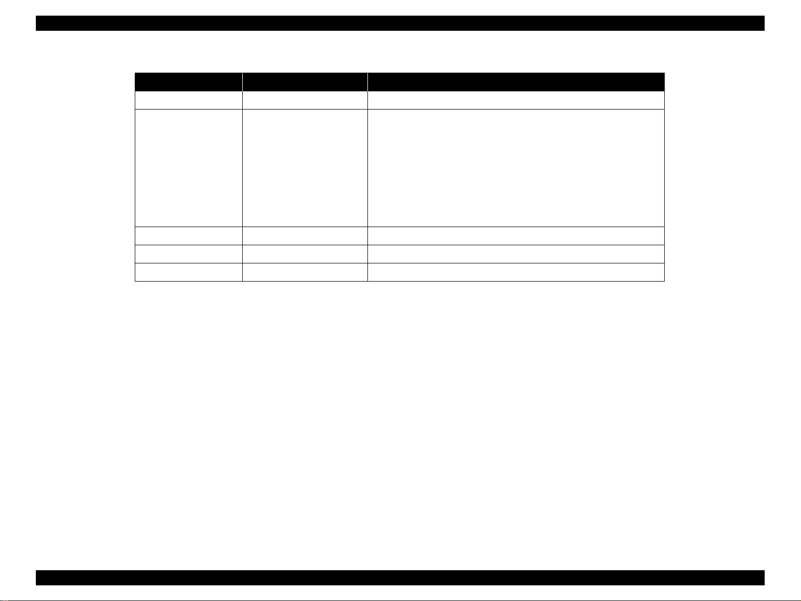
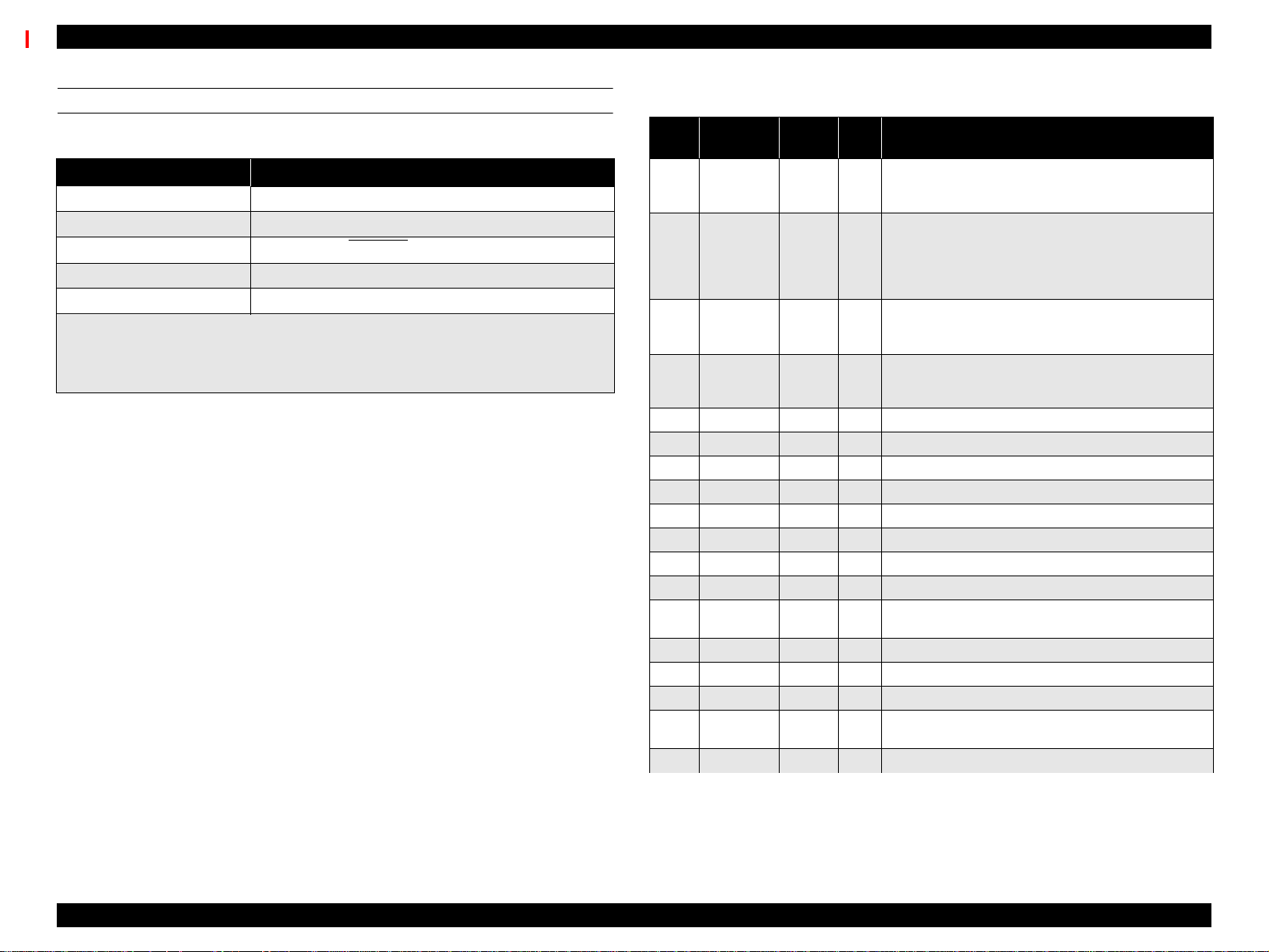
Revision Status
Revision Issued Date Description
A 1/26/1999 Original
The following chapters are revised:
Chapter-1: descriptions for firmware update procedures are corrected.
Chapter-2: descriptions for electrical circuit operation are added.
B 5/28/1999
Chapter-3: Note on usingself-diagnostic mode is added.
Chapter-4: instructions on disassembling the ink system components
are added.
Chapter-5: New tool informaiton is added / “CR Cover position
adjustment” procedure is modified. / Paper sensors adjustment is
added.
4
Page 5

EPSON Stylus Pro 9000 Revision B
Contents
Product Description
Features ...................................................................................................... 10
Professional Color Printing Features ...................................................... 10
Consumable Products & Options ........................................................... 11
SPECIFICATIONS ...................................................................................... 12
Print Specifications.......................................................................... 12
Paper-Feed Specifications .............................................................. 12
Paper Specifications........................................................................ 13
Electrical Specifications................................................................... 16
Conformity/Safety Approvals........................................................... 16
Reliability ......................................................................................... 16
Environmental Specifications .......................................................... 17
Ink Cartridge Specifications............................................................. 18
Acoustic Noise................................................................................. 18
Controller Specifications.................................................................. 18
Cutter Specifications........................................................................ 18
Printer Dimensions & Weight........................................................... 19
Control Panel ............................................................................................. 19
Buttons ............................................................................................ 20
LED indicators ................................................................................. 20
Control Panel Messages ........................................................................ 21
Control Panel Settings ............................................................................ 22
SelecType menu.............................................................................. 22
Test Print Menu............................................................................... 23
Printer Status Menu......................................................................... 23
User Paper Settings ........................................................................ 23
Cutter Replacement Menu............................................................... 24
Gap Adjustment Menu..................................................................... 24
Maintenance Errors ................................................................................ 24
Service Errors ......................................................................................... 25
Service Related Printer Settings ............................................................ 26
Maintenance Mode.......................................................................... 26
Maintenance Mode 2....................................................................... 26
Self-Diagnostic Mode...................................................................... 26
Firmware Update .................................................................................... 27
Updating the Firmware via the PC................................................... 27
Updating the Firmware Via Memory Card....................................... 27
Jumper Settings ..................................................................................... 27
Interfaces ................................................................................................... 28
Serial interface ................................................................................ 28
Parallel interface.............................................................................. 29
TYPE-B Optional interface .............................................................. 31
Buffer operation............................................................................... 31
Initialization ................................................................................................ 32
Interface selection ..................................................................................... 32
Operating Principles
Component List & Illustrations ................................................................ 34
Print Mechanism Components ............................................................... 34
Carriage Components ..................................................................... 35
Paper Feed Path & Components .................................................... 35
Ink System Components ................................................................. 36
Electrical Circuit Boards .................................................................. 36
Description of Components ..................................................................... 37
Carriage Mechanism .............................................................................. 37
CR Guide Rail ................................................................................. 37
Carriage........................................................................................... 38
Paper Feed Assembly ............................................................................ 40
PF Rail............................................................................................. 40
Sensors ........................................................................................... 41
Cleaning Mechanism .............................................................................. 42
Ink Supply Mechanism ........................................................................... 43
Sensors ........................................................................................... 44
Printer Mechanism Operation Outline ..................................................... 46
Carriage Mechanism ....................................................................... 46
5
Page 6

EPSON Stylus Pro 9000 Revision B
Platen Gap Mechanism ................................................................... 46
Paper Feed Mechanism .................................................................. 47
Summary of Control Circuit Operations .................................................. 51
Reset Circuit ........................................................................................... 52
CR/PF Motor Driver Circuit ..................................................................... 52
Head SLID Motor Driver Circuit .............................................................. 53
Pump Motor Driver Circuit ...................................................................... 53
Printhead Driver Circuit .......................................................................... 54
Sensors .................................................................................................. 55
Troubleshooting
Outline ........................................................................................................ 57
Test Points ............................................................................................. 57
Troubleshooting Using the Error Messages ........................................... 57
Errors that require a service technician .................................................. 59
Maintenance Req. 0100 .................................................................. 59
Service Req. 00000100................................................................... 59
Service Req. 00000101................................................................... 59
Service Req. 00010000................................................................... 59
Service Req. 00010001................................................................... 59
Service Req. 00010002................................................................... 60
Service Req. 00010003................................................................... 60
Service Req. 00010004................................................................... 60
Service Req. 00010005................................................................... 60
Service Req. 00010006................................................................... 61
Service Req. 00010007................................................................... 61
Service Req. 00010008................................................................... 61
Service Req. 00010009................................................................... 61
Service Req. 0001000A................................................................... 61
Service Req. 0001000C .................................................................. 61
Service Req. 0001000D
Service Req. 0001000E................................................................... 61
Service Req. 0001000F................................................................... 62
Service Req. 00010010................................................................... 62
Service Req. 00020000 (NVRAM error)
Service Req. 00020001 (Internal RAM error)
Service Req. 00020002 (SRAM error)
Service Req. 00020003 (DRAM error) ............................................ 62
Service Req. 10000004 (CPU GNRL ILLEGAL INSTRCTNS)
Service Req. 10000006 (CPU SLOT ILLEGAL INSTRCTNS)
Service Req. 10000009 (CPU CPU ADDRESS ERROR)
Service Req. 1000000A (CPU DMAC/DTC ADDRESS ERROR)
Service Req. 1000000B (CPU WATCHDOG TIME-OUT ERROR)
Service Req. 100000## (CPU VECTOR 32~63)............................. 62
General Errors ........................................................................................ 63
Ink Low............................................................................................ 63
Paper Out ........................................................................................ 63
Load xxx Paper ............................................................................... 63
Load Paper...................................................................................... 63
Paper Jam ....................................................................................... 64
Cover Open ..................................................................................... 64
Paper Not Cut.................................................................................. 64
Paper Not Straight........................................................................... 64
Reload Paper .................................................................................. 65
Push Lever Down............................................................................ 65
Compartment Open......................................................................... 65
Ink Out............................................................................................. 66
No Ink Cartridge.............................................................................. 66
Remove Paper ................................................................................ 66
Option I/F Error................................................................................ 66
Troubleshooting Based on Your Printout ............................................... 67
Dot Missing...................................................................................... 67
Uneven Printing/Poor Resolution.................................................... 68
Smudged or Marred Printout (Front) ............................................... 68
Smudged or Marred Printout (Reverse side)................................... 68
White or Black Banding ................................................................... 68
Disassembly & Assembly
Summary .................................................................................................... 70
Warnings ................................................................................................ 70
Tools ...................................................................................................... 71
Screw List ............................................................................................... 71
Disassembly Flow ..................................................................................... 72
Removing the Housing ........................................................................... 73
Maintenance Cover Removal.......................................................... 73
H Top Cover Removal..................................................................... 74
6
Page 7

EPSON Stylus Pro 9000 Revision B
L/R Side Covers Removal ............................................................... 75
Front Cover Assembly Removal...................................................... 76
Roll Cover Assembly Removal........................................................ 77
Lower Paper Guide Removal .......................................................... 78
Upper Paper Guide Removal .......................................................... 79
Circuit Board Removal ........................................................................... 80
Power Board Removal..................................................................... 80
C277MAIN Board Removal ............................................................. 81
Printer Mechanism Disassembly ............................................................ 82
Replacing the Waste Ink Pads ........................................................ 83
Replacing the Printheads ................................................................ 85
Removing the CR Motor/Pulley Assembly....................................... 88
Removing the PF Motor Assembly.................................................. 89
removing the hd_SLID motor assembly .......................................... 90
Maintenance Assembly Removal & Disassembly ........................... 91
removing the INterlock switch (L/R)................................................. 93
removing the P_THICK SENSOR ................................................... 94
removing the P_REAR Sensor........................................................ 94
removing the P_FRONT sensor ...................................................... 95
removing the LEVER POSITION SENSOR / hd_SLID HP sensor.. 95
removing the CR-HP sensor and encoder....................................... 96
Ink System Machanism Disassembly ..................................................... 98
Removing the I/C Holder Assembly .................................................... 98
Disassembling the I/C Holder ........................................................... 105
Adjustment
Summary .................................................................................................. 107
Caution ................................................................................................. 107
Adjustment Tools .................................................................................. 107
Adjustment Items .................................................................................. 108
Adjustment Steps .................................................................................... 110
Parameter Backup ................................................................................ 110
Requirements for Backup.............................................................. 110
Backup & Download Procedures................................................... 110
Other/Notes ................................................................................... 111
Firmware Update .................................................................................. 112
Updating Via the PC...................................................................... 112
Updating From a Memory Card..................................................... 112
Self-Diagnostics ................................................................................... 113
Entering Self-Diagnostic Mode ......................................................... 113
Self-Diagnostic Mode Menus ........................................................... 114
Adjustment Menu ................................................................................. 115
Adj Cap Position............................................................................ 117
Adj Check Skew............................................................................ 117
Adj Input Rank............................................................................... 118
Adj Check Nozzle.......................................................................... 119
Adj x Head Slant (B/C heads)........................................................ 120
Adj B/C Head Height ..................................................................... 121
Adj Bi-D ......................................................................................... 122
Head Gap Adjustment................................................................... 124
Flush Point Right and Left Adjustment .......................................... 125
Feed Adjustment........................................................................... 126
Adj Top & Bottom .......................................................................... 127
Adj Rear Sensor Position .............................................................. 128
Test Pattern Print .......................................................................... 129
Clean Head (drain ink)................................................................... 129
Counter Clear ................................................................................ 130
Test Menu ............................................................................................ 131
Version .......................................................................................... 132
Control Panel................................................................................. 132
Sensors ......................................................................................... 133
Sensor Adjustment........................................................................ 134
Encoder......................................................................................... 135
Fan ................................................................................................ 135
Elec. .............................................................................................. 135
Cleaning menu ..................................................................................... 137
Print menu ..................................................................................... 137
Parameter menu .................................................................................. 137
"Initialize" Items............................................................................. 137
"Update" Items............................................................................... 138
Mechanism Adjustment ........................................................................ 138
Carriage Cover Height Adjustment................................................ 139
Cutter Position Adjustment............................................................ 140
CR Steel Belt Tension Adjustment................................................ 141
PF Belt Tension Adjustment.......................................................... 141
Gear Backlash Adjustment............................................................ 142
I/H Lever Position Adjustment ....................................................... 142
P THICK Sensor Assembly Adjustment ........................................ 143
7
Page 8

EPSON Stylus Pro 9000 Revision B
Cover R/L Sensor Assembly ......................................................... 144
Maintenance & Setup
General Maintenance Issues .................................................................. 146
Periodic Maintenance Items ................................................................. 147
Product Life Information ....................................................................... 147
Important Maintenance Items During Service Operations .................... 148
Lubrication ............................................................................................ 148
Unpacking and Installing ........................................................................ 149
The Packaging ..................................................................................... 149
Before Opening the Large & Medium boxes ................................. 149
Contents of the Packaging ................................................................... 150
Medium-size box ........................................................................... 150
Large box....................................................................................... 150
Unpacking and Assembling .................................................................. 151
From unpacking to assembling the Stand ..................................... 151
Assembling the Printer body.......................................................... 154
Appendix
Wiring Diagrams ...................................................................................... 159
Parts List .................................................................................................. 161
Exploded View Diagram .......................................................................... 167
Component Layout .................................................................................. 182
Circuit Diagrams ...................................................................................... 184
8
Page 9

PRODUCTDESCRIPTION
CHAPTER
Page 10

EPSON Stylus Pro 9000 Revision B
1.1 Features
The EPSON Stylus Pro 9000 is an ultra-wide, 6-color ink jet printer with
professional color output. It has the same printheads as the EPSON Stylus
Color 5000. The EPSON Stylus Pro 9000 provides the following major features
and more.
1.1.1 Professional Color Printing Features
Large-size/poster printing
up to B0-wide paper (1118 cm/44 inches) including print-registration marks
Excellent Photo-quality printing
1440 (H) x 720 (V) dpi combined with EPSON’s Microdot printing
High-speed printing
64 nozzles per color (same printhead as the EPSON Stylus Pro 5000)
The RISC-CPU and high-speed color raster ASIC quickly process
detailed print data
A0/Normal Paper: 10 min. approx. (360x360 dpi/Speed)
A0/Glossy Paper: 30 min. approx. (720x720 dpi/Quality)
A0/Glossy Paper: 55 min. approx. (1440x720 dpi/SuperFine)
Low running cost
Six separate ink cartridges so you only have to replace the empty ink
cartridge (each cartridge holds 220 ml)
Auto Rotate feature saves paper by automatically rotating an image if
the width is shorter than the height
Wide compatibility
The following interface alternatives are available:
IEEE-1284 bidirectional parallel interface (supports ECP mode)
Macintosh serial interface (approx. 1.8Mbps)
One Type-B expansion slot for an optional interface
User-friendly features:
Two roll holders for easy switching between paper types
Standard roll-paper cutter
Optional roll-paper take-up reel for automatically winding up your long
printouts
Product Description Features 10
Page 11

EPSON Stylus Pro 9000 Revision B
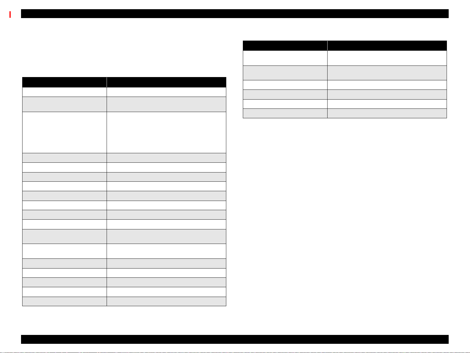
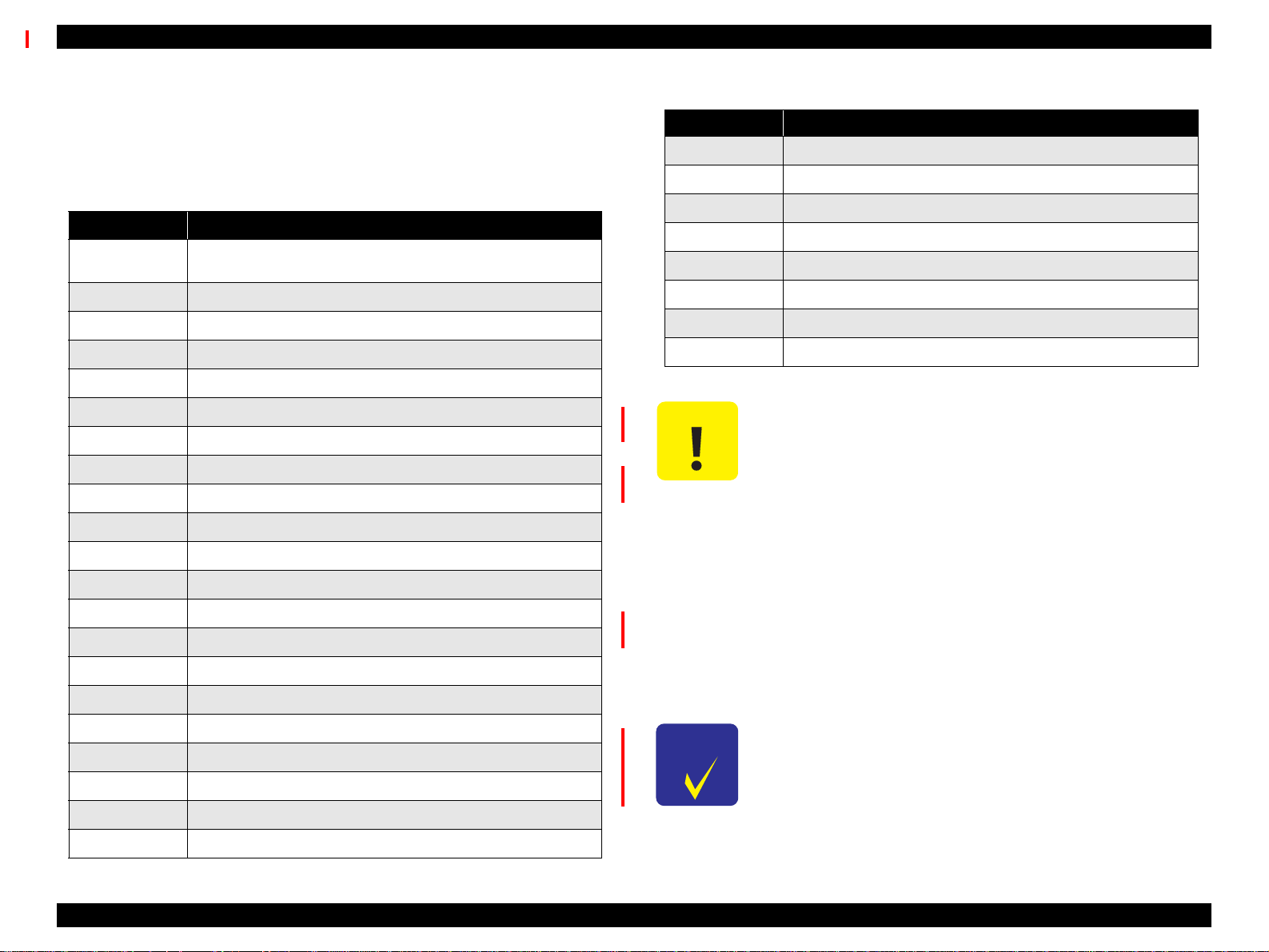
1.1.2 Consumable Products & Options
The following table lists the consumable items and options available for use
with the EPSON Stylus Pro 9000.
Table 1-1. Consumable Products & Available Options
Name Code Product
T407¬¬¬
T410¬¬¬
Ink cartridges
Papercutterblade C815131 Consumable item
Roll Feed Spindle 2” C811021* For two-inch diameter roll paper
Roll Feed Spindle 3” C811031** For three-inch diameter roll paper
Auto Take-Up Reel Unit
Photo Paper (Glossy)
Semigloss Photo Roll
Paper
Matte Roll Paper
Photo Quality Ink Jet
Paper
Photo Paper
Photo Quality Glossy
Film
T409¬¬¬
T408¬¬¬
T412¬¬¬
T411¬¬¬
C81508¬
C815091 (core
only)
S041225
S041224
S041222
S041223
S041221
S041220
S041079
S041068/S041045
S041069/S041043
S041070/S041044
S041142
S041143
S041156
S041073
S041074
S041075
Black Ink
Cyan Ink
Magenta Ink
Yellow Ink
Light Cyan Ink
Light Magenta Ink
Printed roll-paper option
36 in. wide/20.7m long
44 in. wide/20.7m long
36 in wide/25m long
44 in wide/25m long
36 in wide/25m long
44 in wide/25m long
A2
A3
A3 Wide/B
B
A3
A3 Wide/B
B
A3
A3 Wide/B
B
Table 1-1. Consumable Products & Available Options (continued)
Name Code Product
Rip Station 5100 PS
Server Series
Multi-protocol Ethernet
interface card
100Mbps Multi-protocol
Ethernet interface card
Note*:Tworollscanbeinstalledatthesametime.
Note **: Can only be installed in the upper spindle holder.
EAI - C850092
Other - C850093
C82362¬ Type-B 10Base-T
C82363¬ Type-B 100Base-T
Fiery Adobe® PostScript® 3™
Server
Product Description Features 11
Page 12
EPSON Stylus Pro 9000 Revision B
1.2 SPECIFICATIONS
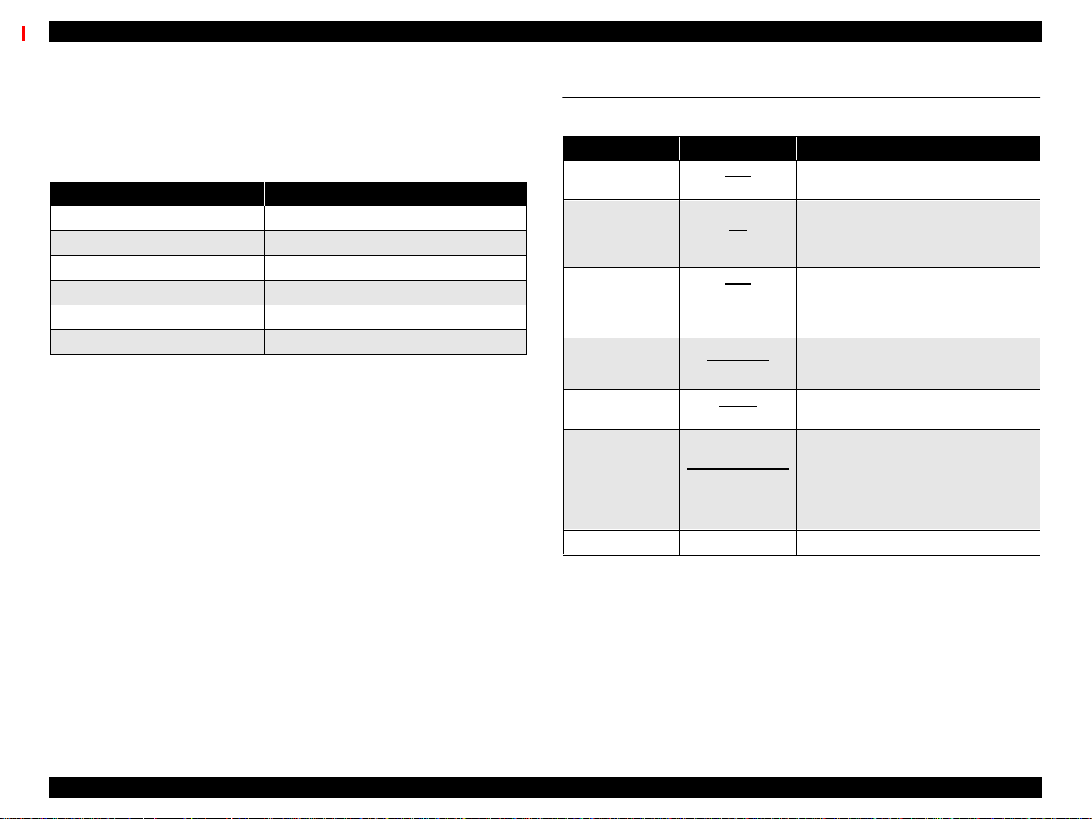
PRINT SPECIFICATIONS
Print method: On-demand MACH (Multi-layer Actuator Head) ink
jet E-MACH type
Nozzle configuration: Black: 64 nozzles
Color: 320 nozzles/64 nozzles for each color (Yellow,
Magenta, Cyan, Light Magenta, and Light Cyan)
Print direction: Bi-directional with logic seeking
(high-speed return and skip only)
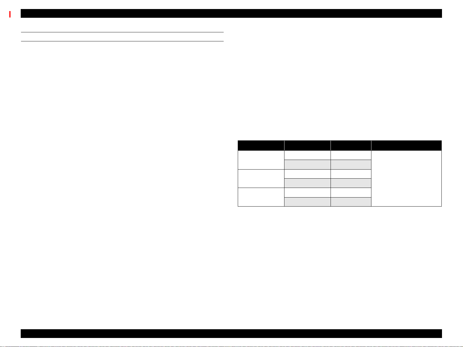
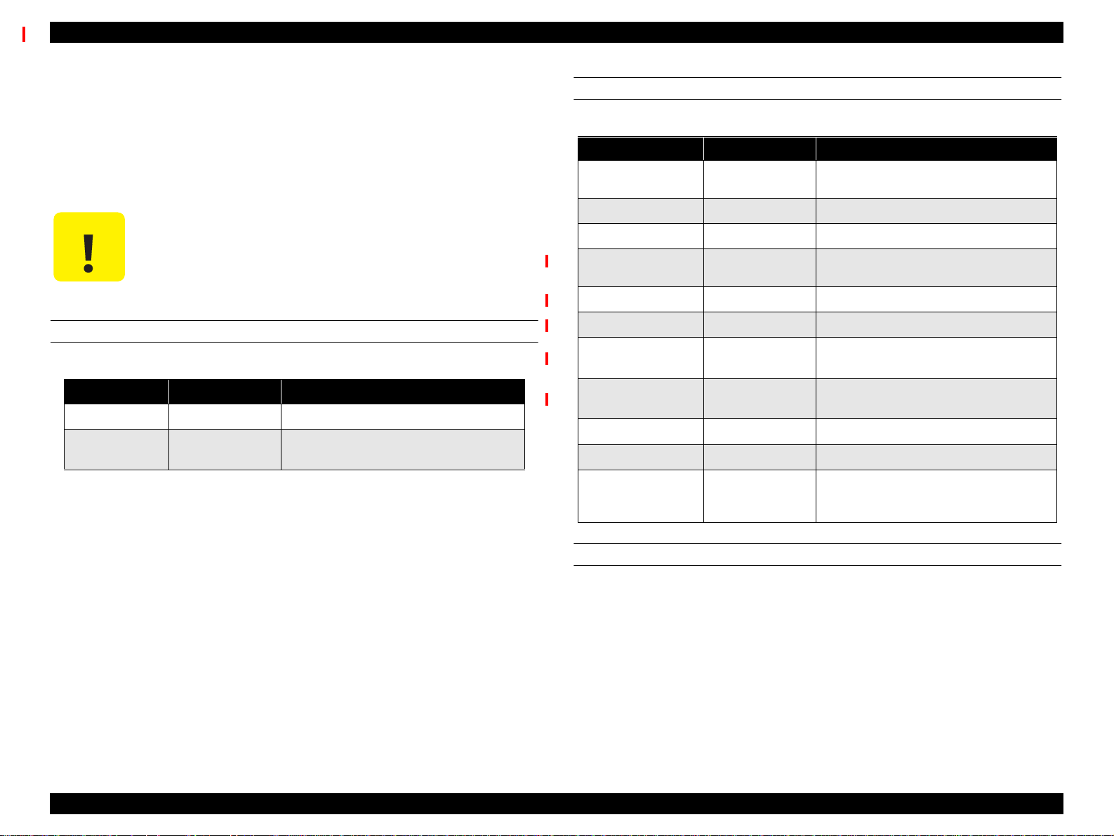
Print speed: See the following table:
Table 1-2. Print Speed
Print Mode A0 Print Time Environment
Matte Paper Approx. 15 min.
Glossy Paper Approx. 30 min.
Glossy Paper Approx. 55 min.
• Speed selected in printer driver
• 720 x 360 dpi
• Mode = Bi-D/FOL/300cps
• Quality selected in printer driver
• 720 x 720 dpi
• Mode = Bi-D/FOL/300cps
• Advanced Photo selected in
printer driver
• 1440 x 720 dpi
• Mode = Bi-D/4-pass FOL/300cps
PAPER-FEED SPECIFICATIONS
Feeding method: Friction feed
Line spacing: 1/6 or 1/720” programmable
Paper loading: Roll paper (two 2-inch rolls can be loaded at the
same time)
Single sheets loaded one at a time
Paper volume: 2” core roll paper = diameter of paper wound on roll
of less than 103mm (4.05”)
3” core roll paper = diameter of paper wound on roll
of less than 150mm (5.9”)
Single sheets = one sheet at a time
Feed speed: 200 ± 10 ms (when feeding at 1/6”)
2.5”/second (when continuously feeding)
Control code: ESC/P Raster (commands are not open to public)
Product Description SPECIFICATIONS 12
Page 13
EPSON Stylus Pro 9000 Revision B
PAPER SPECIFICATIONS
Size, roll paper {
Minimum paper requirements
Paper meeting the requirements described below
can be used with this printer, but neither the feeding
nor printout quality is guaranteed.
•Paper Size = Width 297~1118mm
•Roll Size = 2” or 3” core
•Paper Thickness = 0.08~0.5mm (0.003~0.019”)
{
Normal paper
For paper meeting the following requirements, the
feeding operation only is guaranteed.
•Paper Size = Width 297~1118mm
•Roll Size = 2” or 3” spindle
•Paper Thickness = 0.08~0.11mm (0.003~0.0043”)
•Paper Weight = 64~90gf/m
•Paper Quality = Normal paper, recycled paper
*1: Use at normal room temperature
*2: The printer exerts between 300~500gf to peel
}
(8.27~44.02”)
Length 720mm~45m
(28.35~1771.65”)
paper thickness = 103mm or less (4.05”)
(two 2” rolls)
150mm or less (5.9”)
(one 3” roll)
}
(8.27~44.02”)
Length 720mm~45m
(28.35~1771.65”)
paper thickness = 103mm or less (4.05”)
(two 2” rolls)
150mm or less (5.9”)
(one 3” roll)
2
(17~24 lb.s)
(15~25°C (59~77°F)
40~60% humidity)
off the rear edge of roll paper from the core
*3: Paper feeding is normal until the rear
edge of
the paper separates from the core. At the
point where the rear edge is free, print quality
is not guaranteed.
•Upper spindle = last 400mm (15.75”) not
guaranteed
•Lower spindle = last 300mm (11.8”) not
guaranteed
{
Special paper
}
For special paper meeting the following
requirements, the feeding operation and print quality
are optimized.
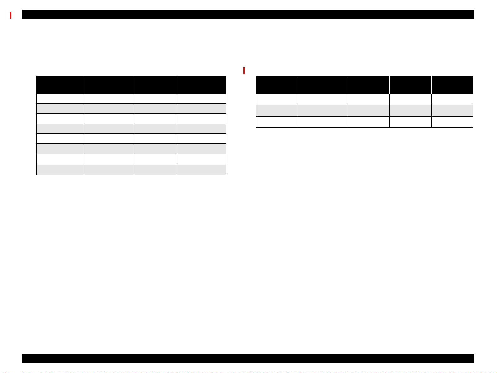
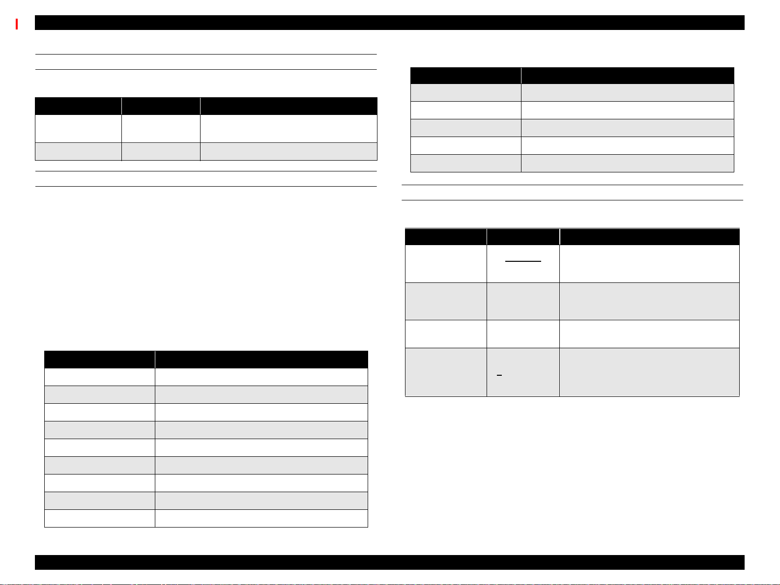
Table 1-3. Special Paper Specifications
Paper Code Paper Size Roll Size
Matte Paper S041220 44” x 25m
S041221 36” x 25m
Semigloss Photo
Paper
Photo Paper
Glossy
S041223 44” x 25m
S041222 36” x 25m
S041224 44” x 25m
S041225 36” x 25m
2” core/ paper thickness
(radius) of 103mm or less
*1: Use at normal room temperature
(15~25°C (59~77°F)
40~60% humidity)
*2: Paper feeding is normal until the rear edge of
the paper separates from the core. At the
point where the rear edge is free, print quality
is not guaranteed.
•Upper spindle = last 400mm (15.75”) not
guaranteed
•Lower spindle = last 300mm (11.8”) not
guaranteed
Product Description SPECIFICATIONS 13
Page 14
EPSON Stylus Pro 9000 Revision B
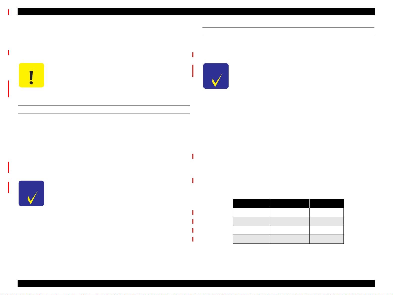
Size, single sheets {
Table 1-4. Usable Single Sheet Paper Specifications
Size
B0 Wide 1118 x 1580mm A2 420 x 594mm
B0 1030 x 1456mm A3 Wide/B 329 x 483mm
B1 728 x 1030mm A3 297 x 420mm
B2 515 x 728mm ANSI E 34 x 44”
B3 364 x 515mm ANSI D 22 x 34”
A0 Wide 914 x 1292mm ANSI C 17 x 22”
A0 841 x 1189mm
A1 594 x 841mm
Minimum paper requirements
}
Paper meeting the requirements described below
can be used with this printer, but neither the feeding
nor printout quality is guaranteed.
Dimensions
(W x H)
Size
ANSI B 11 x 17”
Dimensions
(W x H)
Paper Thickness: 420~728mm (16.54~28.66”) long
paper = 0.08~1.5mm
(0.003~0.059”)
728~1580mm (28.66~62.2”) long
paper = 0.08~0.5mm
(0.003~0.019”)
Special paper
{
}
For special paper meeting the following
requirements, the feeding operation and print quality
are optimized.
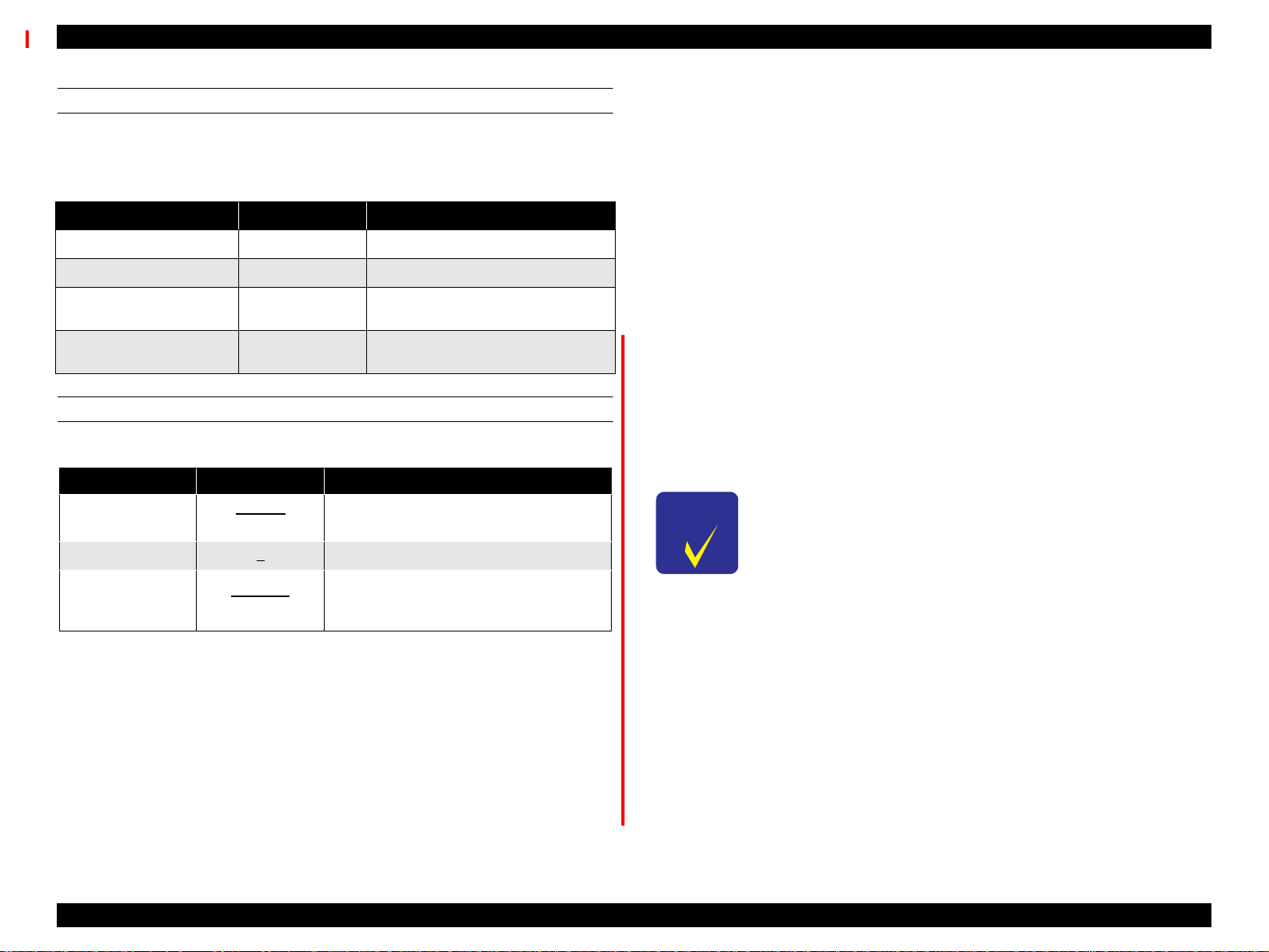
Table 1-5. Special Paper Specifications
Size
A3 297 x 420mm OK OK OK
A3 Wide 329 x 483mm OK OK OK
A2 420 x 594mm OK - -
Notes:
*1: Print quality optimized when printing uni-direction printing
*2: Japan only
Dimensions
(W x H)
SuperFine
*1
PhotoPrint
Paper 2
Glossy Film
*2
{
Normal paper
}
For paper meeting the following requirements, only
the feeding operation is guaranteed.
Paper Thickness = 0.08~0.11mm (0.003~0.0043”)
•Paper Weight = 64~90gf/m
2
(17~24 lb.s)
Paper Quality: Normal, recycled paper
*1: Load short edge first (portrait)
Product Description SPECIFICATIONS 14
Page 15
EPSON Stylus Pro 9000 Revision B
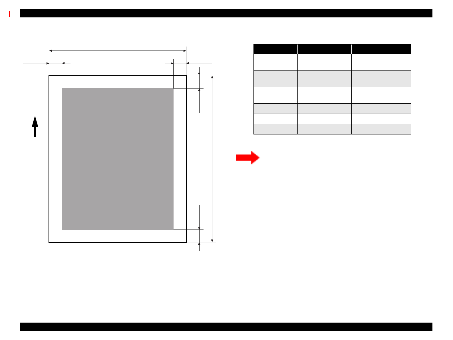
Printable area: See the following illustration and table for details.
PW
LM
RM
TM
Paper
Feed
Printable Area
PL
Table 1-6. Printable Area
Heading Roll Paper Cut Sheets
PW (width)
PL (length)
LM (left margin)
TM (top) 3mm/15mm* 3mm
RM (right) 3mm/15mm* 3mm
BM (bottom) 3mm/15mm* 14mm
Note: *The size of the margin is determined by the control panel setting.
There are three margin settings on the control-panel;
• 3mmAll margins are set to 3mm
• 15mmAll margins are set to 15mm
• T/B 15mmTM and BM are 15mm, while LM and RM are 3mm
297 ~ 1118mm
(8.27 ~ 44.02”)
720mm ~ 45m
(8.27~1771.65”)
3mm/15mm*
(0.12~0.59”)
297 ~ 1118mm
(8.27 ~ 44.02”)
420~1580mm
(16.54~62.2”)
3mm
BM
Figure 1-1. Printable Area
Product Description SPECIFICATIONS 15
Page 16
EPSON Stylus Pro 9000 Revision B
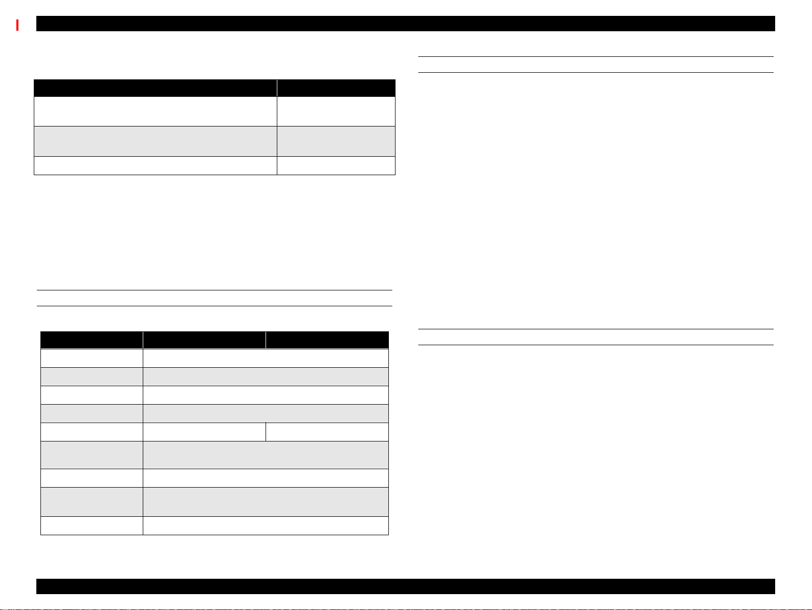
Table 1-7. Print Area/Margin Optimization for Roll Paper
To Optimize for Select this setting
largest printable area and decrease chance of paper
rubbing printheads
exact paper size and decrease chance of paper rubbing
printheads
largest printable area and exact paper size 3mm
Paper Release Lever: {
Release lever is up
}
Top/Bottom 15mm
The feed path is open and you can load, remove or
change the position of paper in the feed path.
{Release lever is down}
The feed path is closed and loaded paper is locked in
place. You can print on the loaded paper.
(It is not possible to change the lever position during
printing.)
ELECTRICAL SPECIFICATIONS
Table 1-8. Electrical Specifications
100V Model 220-240V Model
Rated voltage range AC100~240V
Input voltage range AC90~264V
Rated frequency range 50 to 60Hz
15mm
CONFORMITY/SAFETY A PPROVALS
Safety Standards:
US Model UL 1950, CSA 22.2 No. 950
European Model EN60950 (VDE)
EMC:
US Model FCC part 15 subpart B class B
CSA C108.8 class B
European Model EN 55022 (CISPR Pub. 22) class B
EN 61000-3-2
EN 61000-3-3
EN 50082-1
IEC 801-2
IEC 801-3
IEC 801-4
Australian Model AS/NZS 3548 class B
International Energy Star Compliant
(EPA MOU2.1 Category Large Format Printer)
RELIABILITY
Useful life: Printer = 18,000 pages at B1 size
Printheads = 2,000,000,000 dots/nozzle
Cutter = 2,000 times
Input frequency range 49 to 61Hz
Rated current 1.0A 0.5A
Power consumption
Insulation resistance 10MΩ minimum (between AC line and chassis, DC 500 V)
Dielectric strength
Current leakage 0.25mA maximum
operating = 100W or less
standby mode = 30W or less
AC 1.0KVrms per minute
AC 1.2KVrms per second
Product Description SPECIFICATIONS 16
Page 17
EPSON Stylus Pro 9000 Revision B
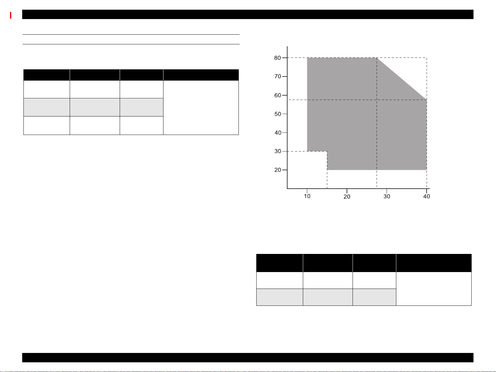
ENVIRONMENTAL SPECIFICATIONS
Temperature/Humidity: See the following table.
Table 1-9. Temperature & Humidity
Condition Temperature Humidity Notes
Operating
Storage
Transportation
Notes:
1) When storing the printer, make sure the printheads are in the home, capped, position.
2) Before transporting the printer, remove the ink cartridges and turn the ink valves screws to
the closed position. Also make sure the p rintheads are in the home, capped, position. After
transporting the printer, install new ink cartridges.
3) When the t emperature drops below -15°C (5
freezes. The ink thaws completely after three hours at 25°C (77
15~35°C
(59~95°F)
-20~40°C
(-4~104°F)
-20~60°C
(-4~140°F)
30~80%
20~85%
5-85%
°F), the ink in the cartridges and printheads
• Less than a month at
40°C (104°F)
• Less than 120 hours at
60°C (140°F)
• Without condensation
°F).
Humidity (%)
Temp.
(°C)
Figure 1-2. Print Temperature and Humidity
Resistance to
Vibration & Shock: See the following table.
Table 1-10. Vibration & Shock Resistance
Condition
Operating 0.15G
Storage 0.50G
Vibration
Resistance
10~55Hz
10~55Hz
Shock
Resistance
1G
less than 1ms
2G
less than 2ms
Notes
X/Y/Z direction
Product Description SPECIFICATIONS 17
Page 18
EPSON Stylus Pro 9000 Revision B
INK CARTRIDGE SPECIFICATIONS
Shape: Each ink cartridge is uniquely shaped so the
cartridges cannot be inserted in the wrong slots.
Ink colors: Black, Cyan, Magenta, Yellow, Light Cyan, Light
Magenta
Ink volume: 220 ± 5 ml
Ink avail. for printing: 190 ± 14ml
Print capacity: A0 = approx. 28 pages at 720dpi and 40% coverage
A0 = approx. 11 pages at 720dpi and 100% coverage
Dimensions: 25.1 x 260 x 105.3mm (WxDxH)
Weight: Approx. 370~385g (cartridge only)
Effective period: 2 years from production (in the sealed packaging)
plus time used (at room temp.)
Storage temperature: See the table below.
Table 1-11. Ink Cartridge (Environmental) Specifications
Situation Temperature Notes
Transporting
Storage
Installed
-30~60°C
(-22~140°F)
-30~40°C
(-22~104°F)
-20~40°C
(-4~104°F)
• Less than month at 40°C (104°F)
• Less than 120 hours at 60°C (140°F)
Less than a month at 40°C (104°F)
Less than a month at 40°C (104°F)
n Do not refill or reuse cartridges; they are consumable items.
n Do not use ink that beyond its expiration date. See above.
n To use ink that has been frozen [below 5 °F(-15°C)], let it
thaw at least 3 hours at room temperature.
ACOUSTIC NOISE
Approximately 50 dB
CONTROLLER SPECIFICATIONS
CPU: 32 bit RISC-CPU (SH7043) 33Mhz
ROM: [Program]
CPU Internal = 128KB ROM
External = 1MB (Flash ROM/4Mbit x 2)
[Font] not-installed (Windows/Macintosh required)
RAM: 18MB (fixed)
(16MB: SIMM/2MB: IC18,19)
Interface: [Standard]
IEEE1284 Bidirectional Parallel Interface
Macintosh Serial Interface
Type-B Card Slot (x1) for optional interface
CUTTER SPECIFICATIONS
Attributes: Consumable item that is replaced by the user, and it
is made of very hard steel, so the blade can easily be
chipped.
Life: Can cut well over 2,000 pages, but the actual wear-
and-tear depends on the type and thickness of the
paper used.
The cutter life can be determined by manually using
it to cut a piece of normal paper. If the cutter easily
cuts the paper, it is OK.
The cutter position is determined by the carriage
cover position; see “Carriage Cover Height
Adjustment” on page 139 and “Cutter Position
Adjustment” on page 140 for more information.
Product Description SPECIFICATIONS 18
Page 19
EPSON Stylus Pro 9000 Revision B
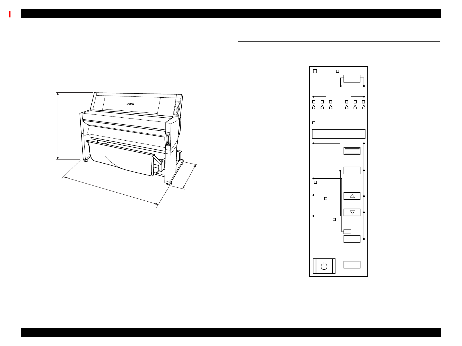
PRINTER DIMENSIONS & WEIGHT
Dimensions: 1688 x 699 x 1259mm (WxDxH)
(66.46 x 27.52 x 49.57 inches)
Weight: 96Kg (211.91 lb.s)
Printer alone = 74Kg (163.32 lb.s)
Stand = 22Kg (48.59 lb.s)
1259mm
(49.57”)
1688mm
(66.46”)
Figure 1-3. Printer Dimensions
699mm
(27.52”)
1.3 Control Panel
This section describes the control panel, the buttons, the lights, and the way
you make settings.]
Ink Out
Paper Source
Pause
Reset
3 sec.
SelecType
Item
+
Paper Feed
_
Operate
KC LCMLMY
Paper Out
Roll
Auto Cut
Roll
Cutter Off
Sheet
Cut /Eject
Enter
Power
Cleaning
3 sec.
Figure 1-4. Control Panel
Product Description Control Panel 19
Page 20
EPSON Stylus Pro 9000 Revision B
BUTTONS
All of the buttons on the control panel, and their functions, are described below.
Table 1-12. Control Panel Buttons & Functions
Button
(Second function)
Power Power on/off N/A N/A
Pause
(Reset)
SelecType
Cut/Eject
(Enter)
Paper Feed ↑ Feeds paper backward *2
Paper Feed ↓
(-)
Paper Source
(Item)
Cleaning
Paper Source
Cut/Eject
Paper Feed ↓
Paper Source
Cut/Eject
Cleaning
Notes:
1: Interrupts ink drying and runs the specified operation.
2: 1.27cm/second paper feed for 2 seconds after key is pressed.
7.62cm/second paper feed if pressed for over two seconds.
Maximum feed of 20cm with one press of the button.
3: 1.27cm/second paper feed for 2 seconds after key is pressed.
7.62cm/second paper feed if pressed for over two seconds.
Function
(Normal)
• Switch - online/off-line
• Reset (press for three
seconds
Enters SelecType mode
(when printerisinStandby
mode)
Selects *1
• Auto Cut
• Cutter Off
• Sheet
Feeds paper forward *3
Selects pa per source
Cleans both heads if
pressed for three seconds
SelecType
Function
N/A
Selects menu or major
category
Confirm and save value
Cycles backward/
increases value
Cycles forward/
decrease value
Selectsitemorminor
category
N/A
N/A
N/A
Power-On
Function
Maintenance
mode
N/A
Maintenance
Mode 2
Firmware
Update Mode
LED INDICATORS
Table 1-13. LED Indicators
LED Status Condition
•On
Operate
Paper Out
•Flashing
•On
•Flashing
•On
Pause
Ink Out Y
Ink Out LM
Ink Out LC
Ink Out M
Ink Out C
Ink Out K
Paper Source
(Auto Cut)
Paper Type
(Cut Off)
Paper Type
(Single Sheet)
Note: *Also occurs if no cartridge is installed or the wrong cartridge is installed.
•Flashing
•On
•Flashing
•On
•Flashing
•On
•Flashing
•On
•Flashing
•On
•Flashing
•On
•Flashing
On Roll paper will automatically be cut.
On
On Single sheet printing mode.
• Power on
• Receiving data or performing power-down
sequence
• No paper loaded
• Paper jam
• Printer ready
• Performing head cleaning or the printer is in ink
drying phase. Also flashes during ink charging
operation.
•Inkout*
•Inklow
•Inkout*
•Inklow
•Inkout*
•Inklow
•Inkout*
•Inklow
•Inkout*
•Inklow
•Inkout*
•Inklow
Roll paper will not be cut. (When using the optional
Take-up Roller, you need to select this setting.)
Product Description Control Panel 20
Page 21
EPSON Stylus Pro 9000 Revision B
1.3.1 Control Panel Messages
Printer status and error messages appear on the control panel display. The
table below lists the messages by order of importance.
Table 1-14. LCD Messages
Display Message Meaning
Service Call nnnnnnnn *2
Maintenance Call nnnn *3
Wait *1
Switching Power Off
Install Ink Cartridge
Cover Open
Option I/F Card Error
Lower Release Lever
Load xxx Paper
Paper Jam
Paper Not Cut
Paper Skew
Paper Out
Reload Pa per
Compartment Open
Replace Cartridge
Press Pause Button
Pause
Fatal error
Printer requires maintenance from qualified service
person (such as replace w aste ink tank)
Resetting Timer IC
Clearing NVRAM
Performing reset operation
Performing ink sequence operation
Initializing the printer
Dealing with initial paper operation
Preparing to shut down.
Replacing ink cartridge.
The cover is open.
A Type-B interface error has occurred.
Paper Release lever is in the release position.
Wrong paper loaded.
Paper is caught inside the printer.
Printer did not cut the paper (when Auto Cut selected)
Paper was fed at an angle, and the printer stopped to
prevent printing the page offcentered.
End of roll or sheet (or the paper detect sensor may
have dust or grime blocking its operation)
Paper check error
Replacing ink cartridge
An ink cartridge is empty
Waiting for paper initialize start t rigger
Pause state.
Table 1-14. LCD Messages (continued)
Display Message Meaning
Ink Drying xx *1
Ink Low
Printing *1
Ready *1
Reset
Restart Printer
Notes:
*1: If the printer’s platen gap setting is set to Thick, a “W” will appear in the last space on the
LCD display.
*2: See “Service Errors” on page 25.
*3: See “Maintenance Errors” on page 24.
Printer waits xx minutes before the next print job to
allow ink on previous print job t ime to dry.
Prepare a replacement cartridge for the color ink
indicated.
Processing print data.
Can receive and print data.
In the process of re-initializing.
Turn the printer off and turn it on again.
Product Description Control Panel 21
Page 22
EPSON Stylus Pro 9000 Revision B
1.3.2 Control Panel Settings
To access the control panel settings, press the SelecType button while the
printer is not printing. The printer enters the SelecType mode and cannot print.
The following table lists LCD display messages in SelecType mode.
Table 1-15. Control Panel Settings
Display Message Menu
SelecType Menu SelecType menu, page 22
Test Print Menu Test Print Menu, page 23
Printer Status Menu Printer Status Menu, page 23
Paper Settings Menu User Paper Settings, page 23
Cutter Replacement Menu Cutter Replacement Menu, page 24
Head Alignment Menu Gap Adjustment Menu, page 24
Selectinga menu provides you with detailed options.
SELECTYPE MENU
Table 1-16. SelecType Menu
Display Message Item Notes
PLATEN GAP
PAGE LINE
INTERFACE
PARALLEL
INTERFACE
CODE PAGE
ROLL PAPER
MARGIN
INITIALIZEPANEL Run Initialize control panel setup values
Notes:
* The printed image is the same size as a printed image using the 3mm setting; however, the
printer adds 12mm of paper clearance (for a total margin of 15mm) to the top and bottom edges
to make paper feeding more stable and to prevent the paper from rubbing the printheads.
Also, the underlined it em equals the default.
Auto
Thick
ON
OFF
Auto
Parallel
MAC
Option
Compatible
ECP
PC437
PC850
Top/Bottom 15mm
15mm
3mm
Adjusts the platen gap. (Normally, leave
set to Auto.)
When Auto Cut Off is selected on the
control panel, this setting determines
whether a line for manual cutting is
printed.
Determines which interface the printer
checks for data. Auto continuously checks
all interfaces and is good for normal use.
Determines the data transfer rate when
using this interface.(Normally, leave set to
Compatibility.)
Character code setting. (PC437:
expanded graphics/PC850: multi-lingual)
Roll sheet margin setting.
• Top/Bottom15mm*: the top and bottom
margins = 15mm while left and right
margins = 3mm
• 15mm: all margins = 15mm
• 3mm all margins = 3mm
Product Description Control Panel 22
Page 23
EPSON Stylus Pro 9000 Revision B
TEST PRINT MENU
Table 1-17. Test Print Menu
Display Message Item Notes
NOZZLE CHECK
PATTERN
STATUS SHEET Print Prints the current printer settings.
Print
Checkthe printout, any missing lines mean
the nozzle(s) are clogged.
PRINTER STATUS MENU
All consumable items and maintenance parts either run out of their contents or
wear out. To determine how much contents (ink) or useful life remains,
compare the message and value shown on the control panel display to the
corresponding value below and the messages in the table below.
E*****F 100~81% full/life remaining
E**** F 80~61% full/life remaining
E*** F 60~41% full/life remaining
E** F 40~21% full/life remaining
E* F 20~1% full/life remaining (generates a warning)
E F Less than 1% full/life remaining (generates an error)
Table 1-18. Printer Status Menu
Display message Meaning
VERSION Shows the firmware version.
INK REMAINING (C) Shows the amount of remaining ink - Cyan
INK REMAINING (M) Shows the amount of remaining ink - Magenta
Table 1-18. Printer Status Menu (continued)
Display message Meaning
WASTE INK Maintenance information
CR MOTOR Maintenance information
PF MOTOR Maintenance information
HEAD UNIT Maintenance information
CLEANING UNIT Maintenanceinformation
USER PAPER SETTINGS
Table 1-19. User Paper Settings Menu
Display Message Item Notes
PAPER NUMBER
THICKNESS
PATTERN
PAPER
THICKNESS NO.
DRYING TIME 0~30 Minutes
Note: The underlined item equals the default.
Standard
1~4
Print
1~17
Select Standard for Epson special paper.
Select the appropriate number for thick
paper.
Prints a pattern to detect the paper
thickness. If “Paper Number” is set to
“Standard”, this message does not appear.
If “Paper Number” is set to “Standard”, this
message does not appear.
Determines the length of time the printer
allows the ink to dry. When printing on roll
paper, the printer will wait the specified time
after printing
INK REMAINING (LC) Shows the amount of remaining ink - LightCyan
INK REMAINING (LM) Shows the amount of remaining ink - Light Magenta
INK REMAINING (Y) Shows the amount of remaining ink - Yellow
INK REMAINING (K) Shows the amount of remaining ink - Black
CUTTER LIFE Shows the remaining useful life of the cutter
TOTAL PRINTS Shows the total number of printed documents
Product Description Control Panel 23
Page 24
EPSON Stylus Pro 9000 Revision B
CUTTER REPLACEMENT MENU
The following table includes the steps/messages that must be followed to
replace the cutter.
Table 1-20. Cutter Replacement Messages
Display Message Item Notes
CUTTER REPLACEMENT Execute Prepare a replacement cutter and
OPEN LOWER COVER - Open the front cover.
REPLACE CUTTER -
CLOSE LOWER COVER -
Remove the old cutter and install a
new one.
Close the front cover. The printer is
ready.
GAP ADJUSTMENT MENU
Table 1-21. Platen Gap Adjustment Menu
Display Messages Item Notes
ADJUSTMENT
PATTERN
SELECT #1-12 1~4~7 Choose a pattern from #1 to #12.
PAPER
THICKNESS
Note: The underlined item equals the default.
Print All
Print #1~12
Standard
0.0~1.6mm
Selectswhichpatternstoprint.(Allpatterns
or selected patterns only.)
Select the thickness, to 0.1mm, of the
paper you are using to check the platen
gap. Normally, leave set to Standard.
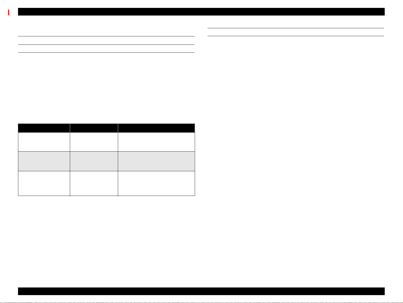
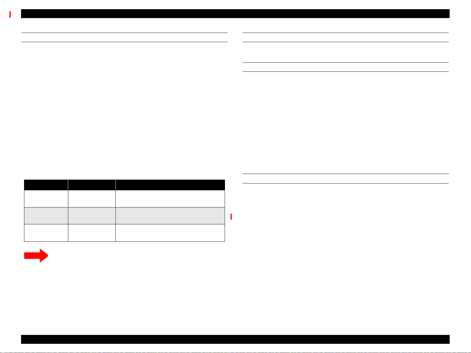
1.3.3 Maintenance Errors
There are several consumable parts in the printer, and the printer employs
separate counters to keep track of each one. The “Maintenance Req. 0100”
message appears on the display to warn that the Waste Ink pads are about
99% full and need to be replaced soon.
The printer can continue to print even though the “Maintenance Req. 0100*
message appears instead of the “Ready” or “Printing” message. However,
when the waste ink counter determines the Waste Ink pads are 100% full, the
“Service Req 00000100” message appears and the printer can no longer print.
To clear the Maintenance error, perform the following.
Replace: The following seven items are need to be replaced.
- Waste Ink Pads (R/L)
- Pump Assembly
- Cap Assembly
-FBox(R/L)
- Cleaner, Head
CHECK
PO INT
Required Adjustments: The following adjustments are need to be performed
The above mentioned seven items are available as a kit.
Description: MAINTENANCE KIT
Parts code: 1048434
after replacing the corresponding items.
- Waste Ink Counter Clear
(See “Maintenance Mode 2” on page -26.)
- Cleaner Counter
(See “Maintenance Mode 2” on page -26.)
- Cutter Position Adjustment
(See “Cutter Position Adjustment” on page 140.)
Product Description Control Panel 24
Page 25
EPSON Stylus Pro 9000 Revision B
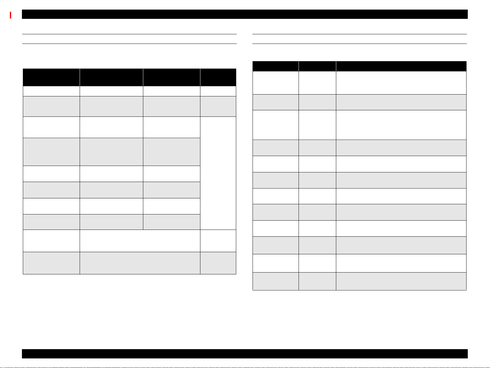
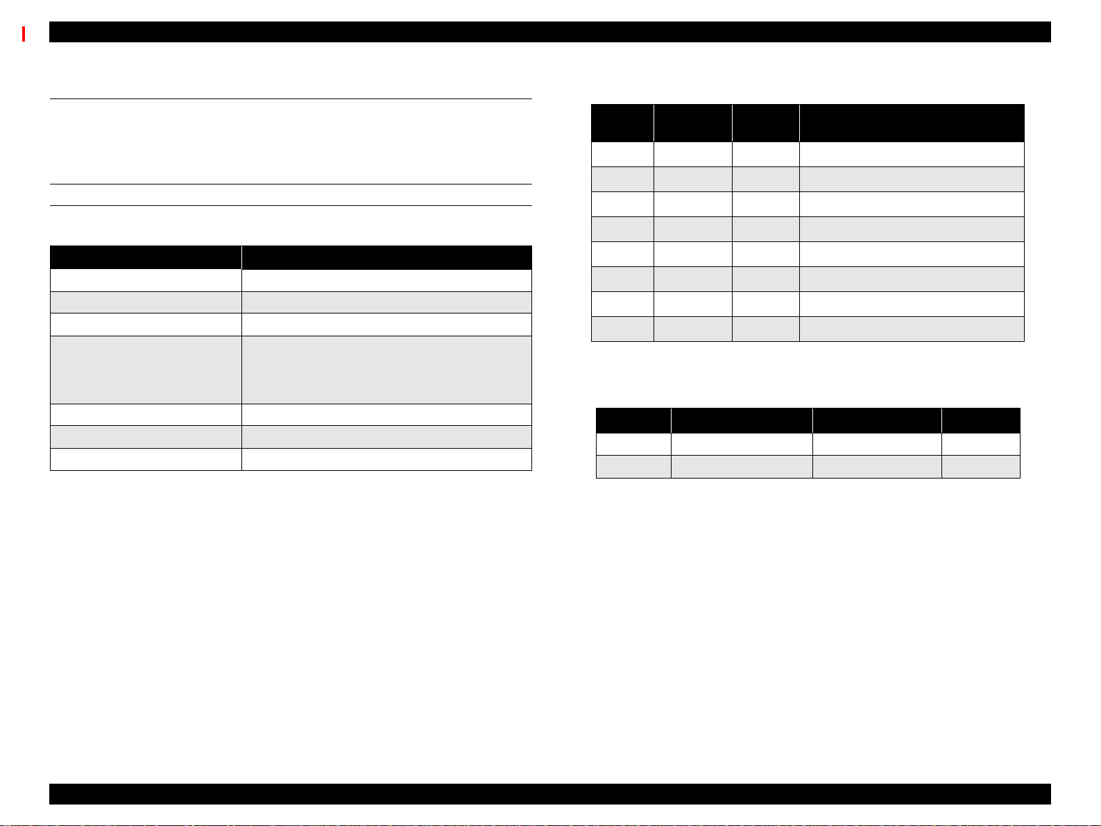
1.3.4 Service Errors
When “Service Req nnnnnnnn” appears on the LCD display, a fatal error
requiring a service technician has occurred. The nnnnnnnn indicates what
needs to be fixed to return the printer to a working state.
Table 1-22. Service Error Code List
Service Code Explanation
00000100
00000101 Ink tubes
00010000 PF Motor Encoder Check error
00010001 PF Motor out of step
000100002 PF Motor overcurrent
000100003 PF Motor in-position time-out error
000100004 CR Motor Encoder Check error
000100005 CR Motor out of step
000100006 CR Motor overcurrent
000100007 CR Motor in-position time-out error
000100008 Servo interrupt watchdog time-out error
000100009 System interrupt watchdog time-out error
00010000A CR origin sensor error
00010000B PF origin sensor error
00010000C PG origin sensor error
00010000D Cover sensor error (00)
Waste ink pads are full and need to be replaced. *1
(Replace the unit and reset the counter.)
Table 1-22. Service Error Code List (continued)
Service Code Explanation
000200002 SRAM Check Error
000200003 DRAM Check Error
100000004 CPU Vector 4 - General illegal instruction
100000006 CPU Vector 6 - Slot illegal instruction
100000006 CPU Vector 9 - CPU address error
10000000A CPU Vector 10 - DMAC\DTC address error
10000000B CPU Vector 11 - Watchdog time-out error
1000000** CPU Vector 32~63
CAUTION
When replacing the following parts to clear “Service Req.
00000100” error, you need to clear the corresponding
counter using “Maintenance Mode 2”.
[Effective parts]
n Waste Ink Pads (right/left)
n F Box (left/right)
n Pump Assembly
n Cap Assembly
n Cleaner, Head
[Effective counters]
n Init. Waste Ink
n Init. Cleaning Unit
00010000E Cover sensor error (01)
00010000F CR motor PWM output error
000100010 PF motor PWM output error
000200000 NVRAM Error
000200001 Internal RAM Check Error
CHECK
PO INT
The above mentioned parts ar e also available as a KIT.
Description: MAINTENANCE KIT
Parts code: 1048434
Product Description Control Panel 25
Page 26
EPSON Stylus Pro 9000 Revision B
1.3.5 Service Related Printer Settings
When the printer is not functioning properly, there are three modes that help
you detect what is wrong and can help you fix the problem. These modes are
“Maintenance Mode”, “Maintenance Mode 2”, and “Self-Diagnostic Mode”. To
enter a mode, press and hold down the appropriate button (described below)
while turning on the printer.
CAUTION
MAINTENANCE MODE
Power-on button: Pause
Message Item Explanation
Hex Dump Print Prints the print data in hexadecimal form
Language
The following explanations regarding control panel service
functions and for service and support purposes only, none
ofthisinformationistobesharedwiththeenduser.
English
Japanese
Determines which language is used to
display messages on the LCD display.
MAINTENANCE MODE 2
Power-on button: Paper Source + Cut/Eject + Paper Feed ↓
Message Item Explanation
INIT. ALL Execute
INIT. NVRAM Execute Initializes NVRAM
INIT. TIMER Execute Initializes timer
INIT. CR MOTOR Execute
INIT. PF MOTOR Execute Initializes PF Motor counter
INIT. HEAD UNIT Execute Initializes Head unit counter
INIT. CLEANING
UNIT
INIT. TOTAL
PRINTS
INIT. INK Execute Initializes ink counter
INIT. WASTE INK Execute Initializes waste ink counter
DETECT INK
LABEL
Execute Initializes cleaning unit counter
Execute Initializes total print counter
ON
OFF
Initializes NVRAM, Timer, life counters,
and mechanical counters
Initializes CR Motor counter (after
replacing ink tubes)
Determines whether the Ink ID sensor
checks the Ink ID label on the ink
cartridge.
SELF-DIAGNOSTIC MODE
Power-on button: Paper Feed ↓ + Cut/Eject + Cleaning
This mode is used primarily for replacing worn-out printer parts and adjustment
operations. For details, see Chapter 5, "Adjustment".
Product Description Control Panel 26
Page 27
EPSON Stylus Pro 9000 Revision B
1.3.6 Firmware Update
The firmware contained onthe Main Board is Flash ROM; therefore if you need
to replace the Main Board or update the firmware, select one of the following
methods.
CAUTION
UPDATING THE FIRMWARE VIA THE PC
1. Make sure the PC is connected to the printer using the parallel port.
Compatible mode connection only.
2. While pressing and holding the following buttons, turn on the printer.
Paper Source + Cut/Eject + Cleaning
3. From the PC, send the firmware-update file to the printer using the
following command. At the DOS prompt, enter
n If for any reason power is cut off during the update
operation (using either method), restart the update
operationtoreturntheprintertonormalstatus.
n Use the following PC card for update.
Name: #F725 Flash Memory Card
Code: 1050073
copy
(filename)
prn:
UPDATING THE FIRMWARE VIA MEMORY CARD
For details on this operation, see Chapter 5, "Adjustment".
1. Copy firmware data file to the PC card.
CHECK
PO INT
2. Make sure the printer is off.
3. Remove the access cover towards the rear of the Paper Guide U, and
insert the Flash memory card containing the updated firmware into the card
slot (CN20).
4. Turn the printer on.
5. “Update complete” appears indicating the Flash ROM has been properly
updated.
6. Turn the printer off, remove the memory card, and turn the printer back on.
The firmware data file to be copied to the PC card is
XXXXXXXX.BIN (Binary format data).
1.3.7 Jumper Settings
CHECK
PO INT
The firmware data file for downloading v ia the PC is
XXXXXXXX.MOT (Motrola format data).
The factory default settings for jumper and DIP switch on the Main Board
(C277MAIN) are as follows.
Table 1-23. Jumper Settings
Type Number Setting
Jumper JP1 Shorted
4. “Update complete” appears indicating the Flash ROM has been properly
updated.
5. Turn the printer off and back on.
Jumper JP2 Shorted
DIP-SW SWD1 “1” (1-4) OFF (Open)
DIP-SW SWD1 “2” (2-3) OFF (Open)
Product Description Control Panel 27
Page 28
EPSON Stylus Pro 9000 Revision B
1.4 Interfaces
The EPSON Stylus Pro 9000 is equipped with parallel and Macintosh serial
interfaces and a card slot for an optional Type-B interface. This section
provides information on each interface.
SERIAL INTERFACE
Table 1-24. Serial Interface
Description
Transmission mode Based on RS-423
Synchronization Synchronous
Transfer speed About 1.8 Mbps
Start bit: 1 bit
Data format
Handshaking X-ON/X-OFF, DTR protocol
Adaptable connector 8-pin mini-DIN
RecommendedI/F cable Apple system peripheral-8 cable (M0197)
Data bit: 8 bits
Parity bit: None
Stop bit: 1 bit
Table 1-25. Pin Assignment
Pin No.
1 SCLK O Synchronous clock signal
2 CTS I Clear To Send
3 TXD- O Transmit Data (-)
4 SG I (Signal Ground)
5 RXD- I ReceiveData(-)
6 TXD+ O Balanced Transmit Data (+)
7 DTR O Data Terminal Ready
8 RXD+ I Balanced Receive Data (+)
X-ON/X-OFF, DTR protocol:
Signal
Name
I/O Description
Table 1-26. X-On/X-Off and DTR Protocol
State Buffer Space X-ON/X-OFF DTR
Busy Less than 3072 bytes Send X-OFF code OFF
Ready More than 5120 bytes Send X-ON code ON
Product Description Interfaces 28
Page 29
EPSON Stylus Pro 9000 Revision B
PARALLEL INTERFACE
Table 1-27. Parallel Interface - Com patibility Mode
Item Description
Transmission mode 8-bit parallel, IEEE-1284 compatibility mode
Synchronization By STROBE pulse
Handshaking By BUSY and ACKNLG
Logic Level
Connector
TTL compatible level (IEEE-1284 Level 1 device)
57-30360 (Amphenol) or equivalent 36-pin
signal
Note 1: Use a twisted-pair cable.
Note 2: The BUSY signal is set high before setting the -ERROR signal low or the PE
signal high. The BUSY signal remains high until all these signals return to their normal
state.
The BUSY signal is high:
n During data entry
n When the input data buffer is full
n When the -INIT signal is low, or during hardware initialization
n During a printer error
n When the parallel interface is not selected
The ERROR signal is low when there is a:
n Printer hardware error (fatal error)
n Paper-out error
n Paper-jam error
n Ink-out error
NOTE: The PE signal is high during a paper-out error.
Table 1-28. Connector Pin Assignments - Forward Channel
Pin
No.
2-9
10
11
12
13
14
15
16
17
18
19-30
31
32
33
34
35
36
Note: “In/Out” is signal direction as viewed from printer.
Signal
Name
STROBE
1
DATA0~7
ACKNLG
BUSY
PE
SLCT
AFXT
NC Not connected
GND Ground for twisted pair return
Chassis Ground for frame/body
Logic H Pulled up to +5V via 3.9Kohm
GND Ground for twisted pair return
-INIT
ERROR
GND
NC
+5V
SLCTIN
The interface condition is normally TTL Level, and each high/low signal takes 0.2uS or less.
The printer only sends data after receiving the ACKNLG confirmation or when the BUSY signal
is low.
Return
Pin
19 I
20-27 I
28 O
29 O
28 O
28 O
30 I
30 I
29 O
---- ----
---- ----
---- O
30 I
In/
Out
Data reception pulse, 0.5uS or greater pulse width
required. Usual state is HIGH, and reads data after
going to LOW state.
The DATA0 through DATA7 signals represent data bit s
0 to7, respectively. Each signal is at high level w hen
data is logical 1 and low level when data is logical 0.
These signals are used to transfer the 1284 extensibility
request values to the printer.
When LOW the printer has finished preparing to receive
signals and can accept data. Pulse width is about 1uS or
3uS Printer clock signal.
HIGH means the printer cannot receive data. This
occurs when the printer is receiving data or when the
printer is in an error state.
HIGH means no paper is loaded. (LOW means an error.)
Always HIGH. Pulled up to +5V via 1.0Kohm
Not used
Pulse width of 50uS or more means LOW pulse, and the
falling edge of LOW signal causes the printer to initialize.
LOW means printer error
Ground for twisted pair return
Not connected
HIGH during normal operation. Pulled up to +5V via
1.0Kohm
Not used
Functional Description
Product Description Interfaces 29
Page 30

EPSON Stylus Pro 9000 Revision B
Table 1-29. Nibble Mode
Description
Transmission mode IEEE-1284 nibble mode
Synchronization Refer to IEEE-1284 specification
Handshaking Refer to IEEE-1284 specification
Signal level TTL level (IEEE-1284 level 1 device)
Connector 57-30360 (Amphenol) or equivalent
Data transfer timing Refer to IEEE-1284 specification
When the printer receives the hexadecimal values 00H or 04H, the printer
responds in the following manner:
00H: The printer enters reverse channel mode, allowing data to be sent to
the host.
04H: The printer sends the device ID to the host; the device ID consists of
the following strings:
Data requests/
device ID
<00H><4EH>
MFG: EPSON
CMD: ESCPL2, BDC
MDL: Stylus[SP]Pro[SP]9000;
CLS: PRINTER
DES: EPSON[SP]Stylus[SP]Pro[SP]9000
Note: [00H] denotes a hexadecimal value of zero.
[SP] equals space code 20H
Table 1-30. ECP Mode
Description
Transmission mode IEEE-1284 ECP mode
Synchronization Refer to IEEE-1284 specif ication
Handshaking Refer to IEEE-1284 specification
Signal level IEE E-1284 level 1 device
Adaptable connector 57-30360 (Amphenol) or equivalent
Data transfer timing Ref er to IEEE-1284 specification
When the printer receives the hexadecimal values 10H or 14H, the
printer responds in the following manner:
10H: The printer enters reverse channel mode, allowing data to be sent
to the host.
14H: The printer sends the device ID to the host; the device ID cons ists
of the following strings:
Data requests/
device ID
<00H><4EH>
MFG: EPSON
CMD: ESCPL2, BDC
MDL: Stylus[SP]Pro[SP]9000
CLS: PRINTER
DES: EPSON[SP]Stylus[SP]Pro{SP]9000
Note: [00H] denotes a hexadecimal value of zero.
[SP] equals space code 20H
Product Description Interfaces 30
Page 31

EPSON Stylus Pro 9000 Revision B
Table 1-31. Connector Pin Assignments - Reverse Channel
Pin
Signal Name
No.
1 HostClk 19 I Host clock signal.
2-9 Data0-7 20-27 I
10 PeriphClk 28 O Printer clock signal
PeriphAck/
11
PtrBusy
12 AckData Req 28 O
13 Xflag 28 O
14 HostBusy 30 I Host busy signal.
15 NC Not connected
16 GND Signal ground
17 Chassis GND Chassis ground
Return
Pin
29 O
In/
Out
The DATA0 through DATA7 signals
represent data bits 0 to7, respectively. Each
signal is at high level when data is logical 1
and low level when data is logical 0. These
signals are used to transfer the 1284
extensibility request values to the printer.
Printer busy signal and reverse channel
transfer data bit 3 or 7.
Acknowledge data request signal and
reverse channel transfer data bit 2 or 6.
X-flag signal and reverse channel transfer
data bit 1 or 5.
Functional Description
TYPE-B OPTIONAL INTERFACE
The EPSON Stylus Pro 9000 supports a Type-B interface (level 2).
Reply message (short version):
n When using Co-ax/Twin-ax interface card:
Main type: MTP48p, PW127cl10cpi, PRG (KAxxxx)rev,
AP1200ma
Product name: Stylus[SP]Pro[SP]9000
Emulation type: ESCPL2-00
Entity type: EPSONLQ2
n When not using a different (not Co-ax/Twin-ax) interface card:
Main type: MTP48p, PW127cl10cpi, PRG (KAxxx)rev,
AP1200ma, SPD0fast
Product name: Stylus[SP]Pro[SP]9000
Emulation type: ESCPL2-00
Entity type: ESPONLQ2
BUFFER OPERATION
When there is no space left in the buffer (4Kb or less), the EPSON Stylus Pro
9000 sends the host a BUSY signal. If the host receives this signal for a long
time, it times out and stops sending data.
18 Logic-H O Pulled up to +5V via 3.9K ohm resister.
19-30 GND Groundfor twisted pair return
31 /INIT 30 I Not used.
32 /DataAvail 29 O
33 GND Ground for twisted pair return
34 NC Not connected
35 +5V ---- O Pulled up to +5V via 3.3K ohm resister.
36 1284-Active 30 I 1284 Active Signal
Data available signal and reverse channel
transfer data bit 0 or 4.
Product Description Interfaces 31
Page 32

EPSON Stylus Pro 9000 Revision B
1.5 Initialization
This section describes the initialization procedures for the EPSON Stylus Pro
9000. There are three ways to initialize the EPSON Stylus Pro 9000:
Hardware initialization:
When the power is turned on or a cold-reset command is sent to the printer
(remote RS command), the printer does the following:
Initializes the printer mechanism
Clears the input data buffer
Clears the print buffer
Restores the default values
Software initialization:
When the printer receives an ESC@ command, it does the following:
Clears the print buffer
Restores the default values
Control panel (operator) initialization:
When the Reset button is pressed or the printer receives an -INIT signal
(negative pulse) from the parallel interface, the printer:
Caps the printheads
Ejects the paper if a cut sheet is loaded
Clears the input data buffer
Clears the print buffer
Resets the default values
The default values are shown below.
Page Position: Current paper position as page-start position
Line feed: 1/6”
Right margin: 440th character
1.6 Interface selection
The printer has three built-in interfaces: parallel, serial, and Type-B (an
optional interface requiring an interface card). These interfaces are selected
automatically or manually through the control panel.
Manual Selection:
Select the desired interface through the default setting mode, described
below under Maintenance Mode (Level 1).
Automatic Selection:
Automatic interface selection is enabled by the default setting mode,
described below under Maintenance Mode (Level 1). When the automatic
selection is active, the printer passively scans all interfaces. The interface
that receives data first is selected as the active interface. When the host
stops sending data and the printer has been in a standby state for 10
seconds, the printer returns to an idle state. Otherwise, the interface
remains active.
Other things to keep in mind about interface selection:
The host checks whether the logic signal is low or high before requesting
data through the reverse channel.
If the parallel interface is not selected, it enters a BUSY state and the logic
signal is set low.
When the serial interface is not selected, the DTR (data terminal ready)
signal is set to MARK.
When the optional type-B interface is not selected, the off-line bit is set to
Main Status Register (MNSTS).
When the printer is initialized or returns to an idle state, the parallel
interface enters a ready condition, the serial DTR signal is set to low, and
the off-line bit of the Main Status Register (MNSTS) is reset.
The /INIT signal on the parallel interface is not active while that interface is
in Nibble or ECP Mode, or is not selected.
Left margin: 1st character
Character pitch: 10 CPI
Print mode: Text mode (non-raster graphics mode)
Product Description Initialization 32
Page 33

OPERATINGPRINCIPLES
CHAPTER
Page 34

EPSON Stylus Pro 9000 Revision B
2.1 Component List & Illustrations
This section explains the print mechanism and operating principles for the
EPSON Stylus Pro 9000.
2.1.1 Print Mechanism Components
The printer mechanism of EPSON Stylus Pro 9000 consists of the following
mechanism parts.
Component Explanation
Carriage Assembly Carriage section:
printheads (B head/C head)
PG Motor
Linear Encoder
HP sensor
PG sensor
Paper Width sensor
Paper cutter-drive component
Carriage guide rail section:
CR Motor
Paper Feed Mechanism Paper feed rail:
Grid roller assembly
Secondary roller assembly (opposite the grid rollers)
PF Motor (Rotary Encoder internal part)
Paper Suction Fans
P_FRONT Sensor (detects front edge)
P_REAR Sensor (detects rear edge)
Paper Thickness Sensor
Paper Release-Lever Position Sensor
Cleaning Assembly
Pump Assembly/Pump Motor
Cap Assembly
CR Lock Mechanism
Component Explanation
Ink Delivery System I/C Holder Assembly
Ink Cartridge Holder/Valve Mechanism
I/H Lever Position Sensor
Ink Cartridge Detect Sensor
Ink Low Sensor
Ink ID Sensor
Other CoverPosition Sensor (interlock switch)
Operating Principles Component List & I llustrations 34
Page 35

EPSON Stylus Pro 9000 Revision B
CARRIAGE COMPONENTS
Carriage
Cover Open Sensor
(interlock switch)
Guide Rail
HP Sensor/
Encoder
CR Motor
PAPER FEED PATH & COMPONENTS
Roll Paper
Holders
Secondary Roller Assembly
P-Thick Sensor
P-Rear
Sensor
Paper
Suction
Fans
PF Motor
Grid Roller
Assembly
P-Front Sensor
Paper Release Lever
Figure 2-1. Carriage Components/Main Parts
Figure 2-2. Paper Feed Components/Main Parts
Operating Principles Component List & I llustrations 35
Page 36

EPSON Stylus Pro 9000 Revision B
INK SYSTEM COMPONENTS
FBox(L)
Waste Ink Pads
Waste Ink Pads (R)
ELECTRICAL CIRCUIT BOARDS
Power Supply Board
I/H Assembly
Main Board
(C277MAIN)
Control Panel
Relay
Board
Pump Assembly
Cap Assembly
CR Lock
FBox(R)
Figure 2-3. Ink System - Main Parts
Figure 2-4. Electrical Circuit Boards
Operating Principles Component List & I llustrations 36
Page 37

EPSON Stylus Pro 9000 Revision B
2.2 Description of Components
2.2.1 Carriage Mechanism
CR GUIDE RAIL
To print on paper as wide as B0 Wide, the printhead carriage must be more
stable and must travel further than the usual carriage. To make the printheads
more stable, EPSON added the CR Guide Rail to the SP 9000.
Every EPSON ink jet printer until now has used a carriage guide shaft to
stabilize the carriage during printing and horizontal movement. SP 9000 does
away with thecarriage guide shaft and relies on the printer frame for its
stability.
The CR motor uses a DC motor to move the carriage, and the Linear Encoder
determines the lateral position of the carriage by counting the shaded areas of
the plastic Step Ruler (timing fence). See Figure 2-5 below. The Linear
Encoder reads the shaded stripes to determine the position of the carriage as
well as the carriage speed, and this data is sent to the software servo. To allow
for the extra distance the carriage must travel during printing, the rubber timing
belt has been changed to a belt made from steel.
The following sensors are used in combination with the CR Guide Rail
components:
Carriage
HP Sensor
Linear
Encoder
CR Guide Rail flag (projected
area)
No HP signal
HP signal
Step Ruler
(plastic strip w/ shaded stripes)
Carriage
Figure 2-5. Carriage Mechanism & CR Guide Rail
HP Sensor
This optical sensor activates when the CR Guide Rail flag (flag) enters the
space between the light emitter and the light receiver. The flag is located
just above the home position, and the HP sensor sends an “On” signal
when the carriage is in the home position.
Linear Encoder
This sensor is located on the back of the carriage, lower than the HP
sensor. For every shaded section the Linear Encoder passes over, the LE
sends a pulse to the CR motor as a PTS (Print Timing Signal). The shaded
sections have a distance equal to 180 dpi, and the software controls use
this spacing for reference purposes.
Operating Principles Description of Components 37
Page 38

EPSON Stylus Pro 9000 Revision B
CARRIAGE
Unlike previous models, the SP 9000 uses a special system to ensure the
distance between the printhead nozzles and paper remains the same for all
supported paper types. The carriage (main) attaches to the CR Guide Rail
using bearings, and the carriage (main) contains the subcarriage. The
subcarriage holds the ink cavities, printheads, and so on.
Carriage
CR Guide Rail
(frame span)
PG Gear
PG Cam
Printhead
Bearings
The subcarriage can be moved using the PG Cam which is driven by the PG
Gears, causing the subcarriage and all its components to move slightly up or
down. The position depends on the thickness of the paper. The position
changes because the PG Cam is somewhat oval shaped and off-centered, so
one side pushes the subcarriage up further than the other side.
The printheads are the same type used in the EPSON Stylus Pro 5000, and
are installed in the same way. Therefore, when installing or replacing the
printheads, make sure neither head leans one way or the other, and make sure
the nozzles of both printheads are exactly lined up vertically. To adjust the
heads, separate adjust levers are provided.
Other sensors and components attached to or related to the carriage are:
P-EDGE sensor
This sensor measures the distance between the right and left edges of the
paper. The light emitted from the sensor is reflected back to the sensor
where paper exists. In this way the sensor determines where the paper’s
edge is and how wide the paper is.
PG origin sensor
This sensor detects when the subcarriage is in the thick paper position or
normal paper position. The PG Gear rotates with the PG Cam, and the PG
origin sensor uses a light-reflecting sensor to determine (according to the
hole in the PG Gear) the current subcarriage position, thick paper or
normal paper.
Subcarriage
(printhead slots)
Figure 2-6. Carriage Mechanism & CR Guide Rail (side view)
Be aware that the PG Cam and the PG Gear (hole) must
line up properlyfor the platen gap adjustment operation
to work properly. The Can and Gear are lined up
properly if when the flattest side of the Cam faces the
Lower Paper Guide, the hole of the Gear faces the CR
steel directly above.
Operating Principles Description of Components 38
Page 39

EPSON Stylus Pro 9000 Revision B
Cutter solenoid
The solenoid is attached to the carriage on the opposite side of the home
position and it activates the cutter to cut roll paper. In order to cut roll paper
evenly, the following method is used:
1) The cutter cuts from the right of center (when facing the printout) to the
right edge.
2) The cutter cuts from several centimeters inside the left edge to the left
edge.
3) The cutter cuts the remaining uncut portion, in the center, from the left
side to the right.
Carriage
Left
edge
Right
edge
Paper Width
sensor
HP side
Carriage
Cutter
solenoid
Cutter
Paper
Paper
Figure 2-7. Paper width sensor
Figure 2-8. Carriage and Cutter Solenoid
Operating Principles Description of Components 39
Page 40

EPSON Stylus Pro 9000 Revision B
2.2.2 Paper Feed Assembly
PF RAIL
The main paper feed components are the CR Guide Rail, the grid roller
assembly which is attached to the PF Rail, and the Secondary Roller Assembly
which attaches to the back of the CR Guide Rail and faces the grid roller
assembly. The grid roller assembly is made up of three equal lengths of rollers
and their coupling.
The PF Motor uses a DC Motor and is controlled by the software servo system
which receives a pulse from the built-in optical rotary encoder. The PF Roller
torque is transferred through the PF Roller shaft edge (left frame), and turns
the PF motor pinion gear and timing belt.
Grid Roller
Assembly
PF Rail
Secondary Roller
Assembly
CR Guide
Rail
Speed-
Reduction
Gear
Platen
Subplaten
Paper
Paper Guide,
PF Motor
Lower
Figure 2-9. Paper Feed Path
Operating Principles Description of Components 40
Page 41

EPSON Stylus Pro 9000 Revision B
SENSORS
The following sensors aid in the paper feeding process.
P-FRONT sensor
This sensor is attached to the back side of the Lower Paper Guide and is
an optical (photo-reflective) sensor. This sensor detects the front edge of
the paper after paper has been loaded but before it is set and ready to
print.
P-REAR sensor
This sensor is attached to the back side of the Upper Paper Guide and is
an optical (photo-reflective) sensor. This sensor detects the rear edge of
the paper as an end of page and detects the front edge when the paper is
first inserted in the paper path.
P-THICK sensor
This sensor physically gauges whether the paper in falls into the normal/
thin category or the thick category. The Secondary Roller unit closest to
the HP has a thin metal flag on top. When the Paper Release Lever is in
the Lock position and thin paper is loaded, this flag enters the space
between the sensor’s light emitter and receiver. However, when thick
paper is loaded the flag is forced forward out of the sensor area, signalling
that thick paper is loaded.
P THICK
Sensor
PaperRelease
Lever
P-REAR
Sensor
Sensor signal = “ON” at 0.7V or less: Normal/Thin paper
Sensor signal = “OFF” at 2.4V or more: Thick paper
Paper Release Lever Position sensor
The Paper Release Lever is located on the right side of the printer, and this
sensor is attached at the bottom of the lever, inside the right-side frame.
This sensor’s signal goes “ON” when the lever is in the lock position,
meaning it is OK to print like a mad man.
P-FRONT Sensor
Paper Release Lever
Position Sensor
Figure 2-10. Paper Feed Sensors
Operating Principles Description of Components 41
Page 42

EPSON Stylus Pro 9000 Revision B
2.2.3 Cleaning Mechanism
The cleaning mechanism for the SP 9000 is similar to the mechanism in the
Stylus Pro 5000. The main components are:
n Pump Assembly (Cleaner, Head)
n Pump Motor (stepping motor)
n Cap Assembly (B head/C head independent)
n Flushing Box R (receives ejected ink during flushing)
n Waste Ink pads
The cleaning mechanism components are installed above the subframe and
some are fixed on the main frame.
Additionally, the following unit is installed above the subframe.
n CR Lock Mechanism
The printer uses an electromagnetic solenoid to activate or release the
carriage lock. The carriage lock comes into effect when the carriage is
in the home position and the CR Motor is not running. When the
carriage lock does not receive any signal, the actuator rises into the
opening at the bottom of the subcarriage, restricting carriage
movement. To release the carriage for printing, the printer signals the
actuator which then moves down, releasing the carriage.
Carriage Cover
Subcarriage Lock
CR Lock
Release
Lever
Figure 2-11. Cleaning Mechanism
Operating Principles Description of Components 42
Page 43

EPSON Stylus Pro 9000 Revision B
2.2.4 Ink Supply Mechanism
The two ink cartridge holders each hold three cartridges, K, C, and M on one
side and Lc, Lm, and Y on the other side. The design of the holders makes it
quite easy to install and replace ink cartridges from the front of the printer. The
I/H Lever opens and closes the I/H door, and at the same time it changes the
angle of the Ink Cartridge Holder Assembly as shown in Figure 2-12, "Ink
Supply Mechanism". To prevent users from accidently installing a color ink
cartridge in the wrong slot, the cartridges have slightly different designs.
Another important feature of the ink cartridge holders is the ink valve, which is
located on the outer sides of the ink cartridge holders and shuts off the flow of
ink during printer transportation. The valve close under the following
conditions:
n The user turns the valve to the “CLOSE” position to transport the
printer.
n The I/H lever is lifted to the up/cartridge install position.
The ink flows out of the ink cartridges, through stainless steel pipes, through
ink tubes, and finally into the printheads.
I/H Lever
Ink Cartridge
Holder Assembly
Figure 2-12. Ink Supply Mechanism
Operating Principles Description of Components 43
Page 44

EPSON Stylus Pro 9000 Revision B
SENSORS
The following sensors are located in the I/H compartment.
I/H Assembly sensor
This optical sensor detects the whether the door is open and the I/H
Assembly is in the install position or the door is closed and the I/H
Assembly is in the printposition.
When the I/H door is open, the signal = ON
When the I/H door is closed, the signal = OFF
Ink Cartridge sensor
This mechanical sensor (microswitch) is built in all six ink cartridge slots.
When the I/C is installed, switch = closed
When the I/C is not installed, switch = open
Ink Low sensor
This mechanical sensor (microswitch) is at the bottom of all six ink
cartridge slots and detects when ink is running out.
When the I/C is nearly empty, the switch = open
When the I/C is not low (normal), the switch = closed
Ink ID sensor
This optical sensor is located at the side of all six ink cartridge slots and
detects the which market the cartridge is for. Although not implemented
currently, the sensor can also detect the type of ink (presently dye only)
and the type of special color (if new colors are introduced in the future).
The Ink ID sensor looks for the following marks on the ink cartridge.
Ink Cartridge
Figure 2-13. Ink Cartridge Holder Sensors
Ink ID Sensor
Ink Low Sensor
Ink Cartridge
Market: No mark, white = Overseas/Global
Ink type No mark, white = dye-based ink
Special color No mark, white = N/A (may be available in future)
Operating Principles Description of Components 44
Page 45

EPSON Stylus Pro 9000 Revision B
Cover open sensor
To ensure proper paper feeding and to prevent paper jams, the front cover
must be closed during printing. There are two cover open sensors, one on
each side of the printer, that detect when the cover is open using an interlock
switch. When the cover is open, the relay that controls the current to the CR
motor and PF motor cuts off the flow of that current. The motors lose their
electromagnetized state when the current is cut off.
Front
Cover
The sudden loss of current to the motors can cause problems and may even
damage the motors or the printhead. To prevent this, a discharge from the
capacitor connected to the current circuit is used to slow down the current
before it is totally cut off. This process ensures that printing stops when the
cover is open without causing any damage to printer parts.
CR
Motor
PF
Motor
Driver
Driver
Front cover
open
C126/127
Figure 2-15. Cover-Open-Motor Control Circuit
Cover Open
Sensor
Figure 2-14. Cover Open Sensor
Operating Principles Description of Components 45
Page 46

EPSON Stylus Pro 9000 Revision B
2.3 Printer Mechanism Operation Outline
This section describes the various parts of the printer mechanism and how
those parts work.
CARRIAGE MECHANISM
The carriage speed is determined by a software servo system. This software
servo is a closed-loop system where the CR motor (DC motor) must provide
constant torque or speed, so an encoder sensor is used to measure the output
and to provide feedback to the motor controller, which adjusts the current or
voltagetothemotoraccordingly.
Print Control
The carriage speed during printing is described below.
Table 2-1. Carriage Speed
Print Mode Carriage Speed
720dpi & Normal M/W 200cps
4 Pass FOL printing 300cps
unidirectional 400cps
Due to the carriage’s quick acceleration process, even after the heads
reach and maintain normal speed, they are not stable enough to print for
the next 10mm.
Stop Control (stop position)
The encoder determines the carriage position by counting the stripes on
the Step Ruler. When the carriage reaches the predetermined position
(defined by the paper-size setting), the carriage stops. To make sure the
carriage has come to a complete stop, the printer checks the encoder for a
certain time (in-position time-out) to make sure no signal is generated
(indicating no carriage movement).
CR Motor Abnormality Detection
The software servo sends a series of pulses to the CR Motor to drive the
carriage a certain distance (depends on current operation, paper size, and
so on). At the same time the encoder measures the distance the carriage
travels. If the position of the carriage according to the Software Servo is
different from the position according to the encoder, a fatal error occurs
(Service Call 00010005).
PLATEN GAP MECHANISM
To maintain a constant distance between the printhead nozzles and the paper,
the printer measures the thickness of the paper and adjusts the height of the
carriage accordingly. The printhead has three platen gap (height) settings, as
described in the table below.
Table 2-2. Platen Gap Settings
Platen Gap Setting Gap Distance
PG “Small” 1.3mm
PG “Medium” 2.2mm
PG “Large” 2.7mm
The actual platen gap position used during printing depends on the paper
thickness as well as the control panel Platen Gap setting.
Table 2-3. Platen Gap Position & PG Settings
Control Panel Setting Platen Thickness Sensor Platen Gap Position
Wide Wide PG “Large”
Standard PG “Medium”
Auto Wide PG “Large”
Standard PG “Small”
Operating Principles Printer Mechanism Operation Outline 46
Page 47

EPSON Stylus Pro 9000 Revision B
PAPER FEED MECHANISM
Paper Suction
The EPSON Stylus Pro 9000 feeds roll paper and cut-sheet paper using
friction-feed, and the sensor along the paper feed path provide all necessary
information for controlling the paper feed process.
Paper Suction Fan
The Paper Suction Fan is located behind the lower paper guide and sucks
air through the holes in the lower paper guide, pulling the paper flat/even
with the lower paper guide. This helps to keep the paper straight as it is fed
through the printer and prevents ink smears.
Fans
Release
lever up?
Yes
No
P-REAR
sensor on?
Yes
P. suction fan level
=low
P-FRONT
sensor on?
Yes
P. suction fan level
=high
Finished
No
P. suction fan
stops
No
Figure 2-16. Paper Suction Fan Operation
Operating Principles Printer Mechanism Operation Outline 47
Page 48

EPSON Stylus Pro 9000 Revision B
Paper size detection - right and left edges
Before printing the printer needs to determine the distance from the right
and left paper edges to the right frame and left frame (home position).
As shown in the following flowchart, the printer flushes the heads to make
sure no ink smears the paper as the printheads move across the paper.
Then the carriage moves to where paper should definitely be (if loaded
properly), near the vertical guide line. There the Paper Width sensor
determines the brightness level (high) of the light reflected off the paper. (If
no light is reflected, paper is not loaded or is not loaded properly and a
“Reload Paper” error occurs.) The carriage moves back toward the home
position, where paper definitely should not be if loaded properly, and
determines the brightness level (low) when light is not reflected off the
paper. This procedure is necessary to set the high/low levels when
adjusting for different media types, such as glossy or plain paper.
edge
Left-top
edge
Dotted line =
printable area
Blackline=paper
Right-
top edge
Next the carriage moves from the home position toward the opposite frame
and measures the distance from the home position to the opposite (right)
edge of the paper according to the brightness high and low levels. If the
paper edge has not been determined by a certain point (outside of the
printheads’ print range), the paper is loaded too far to the right and a
“Reload Paper” error occurs.
Once the opposite-side paper edge has been found, the carriage moves
from the opposite frame to the home position and measure the distance
from the opposite frame to the HP-side (left) edge of the paper.
Error
Error type:
Reload Paper
Detection
Right/LeftEdge
No
No
?
P
H
n
I
suction position
Yes
CR moves to psuedo
Perform regular
flushing
Paper exists?
vertical guideline
CR moves to near
CR moves to
Yes
Yes
Yes
Yes
Return
Paper loaded
No
expected no-paper
Determine “No-
paper” signal level
CR detects paper
edge (HP) side
opposite edge
CR determines
distance from HP to
(signal goes low)
Paper exists?
No
Opposite edge is
determined
distance from
CR determines
Paper exists?
side paper edge
opposite side to HP-
No
The edge on HP
side is found
Operating Principles Printer Mechanism Operation Outline 48
Page 49

Operating Principles Printer Mechanism Operation Outline 49
Leading edge
detection
Perform regular
flushing
Stop suction fans
Max. reverse feed
200mm
CR moves to 30mm
inside left edge
Before beginning this
procedure, the printer must
determine the sensor’s high
and low reflection levels (see
page 48).
edge.
Before printing the printer needs to determine the location of the front
Paper size detection - front edge
EPSON Stylus Pro 9000 Revision B
Figure 2-17. Paper-size detection of l eading edge
P-Front sensor
= on?
Yes
Max. reverse
feed,
P-Front sensor
Reverse feed +40mm
CR moves to preset
position
Max. reverse feed and
feed paper until
P-Front = off
P-Width sensor
=off?
Yes
Printer detects
leading edge
No
No
Black line = paper
Dotted line =
printable area
Right-top
edge
edge
Left-top
edge
Right-topedge
detected?
No
CR moves to 30mm
inside right edge
Return
Yes
Error
Error type:
Reload Paper
Page 50

EPSON Stylus Pro 9000 Revision B
Paper condition detection
After paper is loaded in the printer, the printer performs the above left,
right, and leading edge detection operations to make sure the paper not
outside of the printable range of the printheads. If any of these edges is
outside of this area, a “Reload Paper” errors.
Basic loading procedure
Make sure the left edge (near the HP) is lined up with the vertical line
of holes in the Lower Paper Guide.
Normal loading area
Paper loaded within 10mm of the center of the vertical line of holes in
the Lower Paper Guide is considered in the printable zone; however,
paper loaded outside that 10mm zone causes an error.
Paper skew
In order to avoid printing on paper that is skewed or fed at a slant too far to
the right or left, the printer detects the right and left edges at the leading
edge of every page. If the printer determines that the paper is skewed 3mm
or more compared to the previous page, a “Paper Not Straight” error
occurs.
Basics
The right and left edge positions are checked at the top of every page.
Degree of skew
Any change in the edge position (from the originally detected position)
over 3mm causes an error.
Operating Principles Printer Mechanism Operation Outline 50
Page 51

EPSON Stylus Pro 9000 Revision B
2.4 Summary of Control Circuit Operations
This section summarizes the functions of the (C277MAIN) Main Board and the
controls used to operate the printer.
IC8
CPU/C90A08CA
(SH7043)
IC13
ASIC/E05B61AA
CN7
Control Panel
IC39
SRAM/8KB
IC18/19
DRAM/2MB
CN19
RAM-SIMM/16MB
IC1/2
Flash mem./1MB
CN2
Type-B Slot
CN3
Mac Serial I/F
CN1
Parallel I/F
Fixed
-Firmware
-Setting parameters
Table 2-4. C277MAIN Board Main Components
Name/Code Location Function
CPU (C90A08CA)
SH7043
IC8
ASIC (E05B61AA) IC13
ASIC (TE7751) IC20
ASIC (uPD65802) IC32
32 bit RISC-CPU
o Clock speed = 33MHz
o 128KB PROM internal
1) Regulates print data
o Command handling
o Rasterizer (image data handling)
o Head drive regulation (DAC)
o Print timing regulation
2) Memory (DRAM/SRAM)
3) I/F Circuit Control
o Parallel interface (IEEE1284)
o Macintosh Serial interface
o Type-B
Regulates Motor
o Pump Motor
o PG Motor (PG setting)
o Fan (PS, Paper Suction)
Regulates motor (PWM regulation)
o CR Motor
o PF Motor
3 channel 10 bit DA converter
o head-drive voltage control
Flash Memory (1Mbyte)
o Save firmware
o Register setting parameters
EDO RAM
o 2Mbyte
o 16Mbtye (CN19 mounted SIMM)
64Kbit SRAM
o External data ring buffer type
Motor
drivers
Printer
mechanism
IC32
ASIC/uPD65802
CR
IC35
PF
MotorPGMotor
IC33
Motor
IC20
ASIC/TE7751
IC30
IC31
Pump
Motor
CN20
PC Card connector
Head data & control signals
IC37
DAC/M65530FP
B head C head
Head-drive voltage
common driver
Printheads (B/C)
Head-drive wave
generation
DAC (M65530FP) IC37
Flash Memory
(MBM29F400TC)
IC1/2
DRAM (EDO) IC18/19
SRAM (LC3564SM-
10)
IC39
Driver IC (L6203) IC33/35 CR/PF Motor Driver
Figure 2-18. C277MAIN Board-Circuit Block Diagram
Driver IC (LB1845) IC30/31 PG/Pump Motor Driver
Operating Principles Summary of Control Circuit Operations 51
Page 52

EPSON Stylus Pro 9000 Revision B
2.4.1 Reset Circuit
The Reset-IC (IC7/BH6150F) used in the C277MAIN board has two built-in
reset circuits, each of which detects input voltage and power supply voltage
respectively as shown in the diagram on the right.
Pin 2 detects the voltage level of the head driver, using the input terminal of the
input voltage detection circuit. The voltage level to be detected is preset at
1.25V. When the preset voltage level is detected, the Pin 2 sends a reset
signal to reset the mechanism control circuit.
Pin 8 detects the voltage level of the logic power supply, using the input
terminal of the power supply voltage detection circuit. The voltage level to be
detected is preset at4.2V. When the preset voltage level is detected, the Pin 8
sends a reset signal to reset the main logic circuits.
2.4.2 CR/PF Motor Driver Circuit
The EPSON Stylus Pro 9000 uses the DC servomotor to drive the CR and PF
motors. Therefore, the encoder is installed to detect the position, direction, and
speed of the carriage, and feedback from the encoder enables the software
servo control system to control the CR/PF motors.
The signal received from the Pin 60/61 in the IC32 enables the chopping
control system to control the output from the motor drive IC, and the output
from the Pin 10 in the motor drive IC (IC35/33) feeds back the output current
level to the IC32.
The Electro-magnetic Relay (LA1/LA2) is located on the power supply line for
the DC/PF motors, and it cuts off the power supply when the front cover is
open.
Figure 2-19. Reset Circuit
Figure 2-20. CR/PF Motor driver circuit
Operating Principles Summary of Control Circuit Operations 52
Page 53

EPSON Stylus Pro 9000 Revision B
2.4.3 Head SLID Motor Driver Circuit
The Head SLID Motor vertically adjusts the position of the printhead on the
carriage according to the thickness of the media in the printer. The motor is
driven by the constant current bipolar drive system, and the current supply to
the motor is controlled by the PWM current control system. The 4-phase 48pole PM pulse motor is used for the drive motor, and it is driven by the W1-2
phase excitation.
Based on the preset data received from the IC20, the motor driver IC (IC31)
determines the current level to be output to the motor, and the motor is driven
by the drive phase switching signal which is input into the Pin 25/18.
2.4.4 Pump Motor Driver Ci rcuit
The 4-phase 200-pole HB stepping motor is used to enable the ink system to
conduct ink absorption. The basic control method and the circuit configuration
are the same as those of the Head SLID Motor Driver Circuit.
Figure 2-22. Pump Motor driver circuit
Figure 2-21. HD_SLID Motor driver circuit
Operating Principles Summary of Control Circuit Operations 53
Page 54

EPSON Stylus Pro 9000 Revision B
2.4.5 Printhead Driver Circuit
The EPSON Stylus Pro 9000 uses the same printhead as that of the EPSON
Stylus Pro 5000 (both dark-color head and light-color head), and the basic
configuration of the driver control circuit is also the same.
Print data is rasterized on the memory (DRAM). Triggered by the LAT signal
(BHLAT, CHLAT), the IC13 reads the print data in the format and the order
according to the print mode, and transfers the data to the printhead (driver
circuit on the printhead) synchronizing with the clock signal (BHCLK, CHCLK).
The IC13 is equipped with the counter function, which keeps count of each
color’s data "1" being transferred to the printhead, and the accumulated count
is used to calculate the ink consumption.
The waveform signal is processed at the IC13. Triggered by the input of the
PTS signal from the CPU (IC8), the waveform signal is input into the DAC in
the IC37 as 10-bit data, synchronizing with the clock signal (20mHz). The DAC
then converts the head driver voltage waveform data to analog data, and
outputs it to the trapezoid waveform generation circuit (common driver).
The driver circuit on the printhead (nozzle selector) receives the serial data on
nozzle selection ("H" level = printing nozzle / "L" level = non-printing nozzle)
from the IC13. The circuit then latches the data to the data latch using the LAT
signal, and selects the printing nozzles and non-printing nozzles. Once the
nozzles are selected, the trapezoid waveform generation circuit (common
driver) generates the trapezoid waveform to fire ink. The NCHG signal
(BHNCHG, CHNCHG), which is input into the printhead from the IC13,
prepares all the nozzles for the next firing by applying slight vibrations during
the non-printing phase.
Figure 2-23. Printhead driver circuit
Operating Principles Summary of Control Circuit Operations 54
Page 55

EPSON Stylus Pro 9000 Revision B
2.4.6 Sensors
The output signal sent from each sensor of the EPSON Stylus Pro 9000 is
connected to each IC on the control circuit as shown in the diagram on the
right.
In order to process the detected results as analog signal, the following sensors
input the results into the analog port in the CPU (IC8) via comparator. The
analog signal is then converted to the digital signal by the CPU built-in ADC
(10-bit) and is compared with the standard value for state analysis.
o P_REAR Sensor
o P_FRONT Sensor
o P_EDGE Sensor
Thermister is attached to the printhead to monitor the temperature around the
printhead, and it feeds back the detected temperature to the CPU, which in turn
conducts the driver voltage adjustment according to the temperature detected.
Figure 2-24. Sensors
Operating Principles Summary of Control Circuit Operations 55
Page 56

TROUBLESHOOTING
CHAPTER
Page 57

EPSON Stylus Pro 9000 Revision B
3.1 Outline
This section describes how to diagnose printer errors as well as how to resolve
them. Troubleshooting is divided into the following categories.
Troubleshooting using the error messages
Troubleshooting based on printout
In addition to the above troubleshooting points, this section covers check
points as well.
3.1.1 Test Points
The following table lists the test points for electrical components.
Table 3-1. Test Points for Electrical Components
Component Standard
CR Motor Armature resistance: 10.0 ohm
PF Motor Armature resistance: 2.3 ohm
SLID Motor Coilresistance: 17.5 ohm
PUMP Motor Coil resistance: 3.9 ohm
Cutter Solenoid Coil resistance: 58 ohm
3.2 Troubleshooting Using the Error Messages
The EPSON Stylus Pro 9000 performs self-diagnostic tests using the data
supplied by its various sensors, and if an error is detected by one or more
sensors, a corresponding error message appears on the control panel display.
No matter what kind of error occurs, use the Error Message List for Service
Technicians table on page 58 or the General Error Message List table on page
58 to determine what and where the problem is, as well as where to look for
directions on fixing the problem.
Table 3-2 lists the printer errors that require service technicians to check
and troubleshoot, such as failed part replacement.
Table 3-3 lists the printer errors that users can check and troubleshoot by
themselves.
See “Elec.” on page 135 for instructions on how to
access a list of the last seven fatal errors.
CR Lock Solenoid Coil resistance: 58 ohm
Troubleshooting Outline 57
Page 58

EPSON Stylus Pro 9000 Revision B
Table 3-2. Error Message List for Service Technicians
Error Code Description Refer to
Maintenance
Req. nn
ServiceReq.
nnnnnnnn
0100
00000100 Waste Ink pads must be replaced
00000101 Ink Tube worn out
00010000 PF moto r encoder check error
00010001 PF mot or out of step
00010002 PF motor overcurrent
00010003 PF in-position time-out
00010004 CR motor encoder check error
00010005 CR motor out of step
00010006 CR motor overcurrent
00010007 CR in-position time-out
00010008 Servo interrupt watchdog time-out error
00010009 System interrupt watchdog time-out error
0001000A CR origin sensor malfunction
0001000C PG origin sensor malfunction
0001000D Cover sensor malfunction (00)
0001000E Cover sensor malfunction (01)
0001000F CR motor PWM output error
00010010 PF moto r PWM output error
00020000 NVRAM err or
00020001 Internal RAM check error
00020002 SRAM check error
00020003 DRAM check error
10000004 CPU vector 4 - General illegal instruction
10000006 CPU vector 6 - Slot illegal instruction
10000009 CPU vector 9 - CPU address error
1000000A CPU vector 10 - DMAC/DTC address error
1000000B CP U vector 11 - Watchdog time-out error
100000”” CPU vector 32~63
Waste Ink pads is almost full (less than 1%
remaining)
page 59
page 59
page 59
page 59
page 59
page 60
page 60
page 60
page 60
page 61
page 61
page 61
page 61
page 61
page 61
page 61
page 61
page 62
page 62
page 62
page 62
page 62
page 62
page 62
page 62
page 62
page 62
page 62
page 62
Table 3-3. General Error Message List
Error Type Message Refer to
Warning Ink Low page 63
Paper Out page63
Load xxx Paper page 63
Load Paper page 63
Paper Jam page 64
Cover Open page 64
Paper Not Cut page 64
Paper Not Straight page 64
Error
Reload Paper page 65
Push Lever Down page 65
Compartment Open page 65
Ink Out page 66
No Ink Cartridge page 66
Remove Paper page66
Option I/F Error page 66
Troubleshooting Troubleshooting Using the Error Messages 58
Page 59

EPSON Stylus Pro 9000 Revision B
3.2.1 Errors that require a service technician
This section describes the errors listed in Table 3-2 on page 58 in detail.
MAINTENANCE REQ. 0100
Problem
The waste ink pads have absorbed 99% of their potential. The printer can
continue printing, but the “Maintenance Req. 0100” message appears
instead of the “Ready” or “Printing” messages.
Solution
Replace the following parts and reset the ink counter
Waste Ink Pads (right, left)
F Box (right, left)
Pump Assembly
Cap Assembly
Cleaner, Head
SERVICE REQ. 00000100
Problem
The waste ink pads are completely full, causing a fatal error. The printer
stops printing.
Solution
See the solution for Maintenance Req. 0100.
SERVICE REQ. 00000101
Problem
A printer part has exceeded its useful life, and to prevent damage to other
parts as well as abnormal operations/printouts, an error occurs. This error
occurs when the CR Motor has reached 2.5 million passes, and this
indicates the Ink Tubes should be replaced due to excessive wear and
tear.
Solution
To make sure the Ink Tube is not worn out, verify no part of the tube shows
wear, is loose, or leaks ink anywhere, especially the tube area between the
printheads and the ink pipes.
SERVICE REQ. 00010000
Problem
PF motor encoder check error
The PF motor makes small revolutions clockwise and counter-clockwise.
When it turns, the printer checks the rotary encoder output signals to make
sure the motor is turning at the correct speed/distance. If there the encoder
doesn’t send the correct signal or output data, an error occurs.
Solution
Make sure there is nothing blocking the grid rollers. If that does not solve
the problem, check the PF motor encoder connection. If there still is a
problem, try the following.
Check and adjust the PF Belt tension
Replace the PF motor
Replace the Main Board
SERVICE REQ. 00010001
Problem
PF motor out of step - the length of the PF motor internal encoder’s pulse is
too long or too short compared to the regular pulse.
Solution
Make sure there is nothing blocking the grid rollers. If that does not solve
the problem, check the PF motor encoder connection. If there still is a
problem, try the following.
Check and adjust the PF Belt tension
Replace the PF motor
Replace the Main Board
Troubleshooting Troubleshooting Using the Error Messages 59
Page 60

EPSON Stylus Pro 9000 Revision B
SERVICE REQ. 00010002
Problem
PF motor overcurrent - Feedback from the PF motor (IC35) driver’s 10-pin
output (sensor signal) indicates that the PF motor’s current is irregular.
Solution
Replace the PF motor
Replace the Main Board
SERVICE REQ. 00010003
Problem
PF in-position time-out - The in-position time is the amount of time the
printer waits to make sure the carriage is not moving when the carriage
comes to a stop. The rotary encoder is activate for the predetermined “inposition time” and if the encoder sends a pulse, this means the carriage is
moving even though it is supposed to be at a full stop, this generates an
error.
Solution
Replace the PF motor
Replace the Main Board
SERVICE REQ. 00010004
Problem
CR motor encoder check error
The CR motor makes small revolutions clockwise and counter-clockwise.
When it turns, the printer checks the encoder output signals to make sure
the motor is turning at the correct speed/distance. If the encoder doesn’t
send the correct signal or output data, an error occurs.
Solution
Make sure there is nothing blocking the carriage. If that does not solve the
problem, check the CR motor encoder connection. If there still is a
problem, try the following.
Check the plastic step ruler for soiled areas, obstructions, and damage
Replace the encoder sensor
Replace the CR motor
Replace the Main Board
SERVICE REQ. 00010005
Problem
CR motor out of step - the length of the CR motor’s pulse is too long or too
short compared to the regular pulse.
Solution
Make sure there is nothing blocking the carriage. If that does not solve the
problem, check the CR motor encoder connection. If there still is a
problem, try the following.
Check the plastic step ruler for soiled areas, obstructions, and damage
Replace the encoder sensor
Replace the CR motor
Replace the Main Board
Troubleshooting Troubleshooting Using the Error Messages 60
Page 61

EPSON Stylus Pro 9000 Revision B
SERVICE REQ. 00010006
Problem
CR motor overcurrent -Feedback from the CR motor (IC33) driver’s 10-pin
output (Sense signal) indicates that the PF motor’s current is irregular.
Solution
Replace the CR motor
Replace the Main Board
SERVICE REQ. 00010007
Problem
CR in-position time-out - The in-position time is the amount of time the
printer waits to make sure the carriage is not moving when the carriage
comes to a stop. The linear encoder is activate for the predetermined “inposition time” and if the encoder sends a pulse, this means the carriage is
moving even though it is supposed to be at a full stop, this generates an
error.
Solution
Replace the encoder sensor
Replace the CR motor
Replace the Main Board
SERVICE REQ. 0001000A
Problem
CR origin sensor malfunction - CR home position sensor malfunction
Solution
Replace the HP sensor
Replace the Main Board
SERVICE REQ. 0001000C
Problem
PG origin sensor malfunction (may indicate PG motor malfunction)
Solution
Make sure there is no ink or dust on the surface of the sensor. If this does
not solve the problem, check the PG sensor connection. If there still is a
problem, try the following.
Replace the PG sensor
Replace the PG motor
Replace the Main Board
SERVICE REQ. 0001000D SERVICE REQ. 0001000E
Problem
SERVICE REQ. 00010008
Problem
Servo interrupt watchdog time-out error due to motor-drive control related
error
Solution
Replace the Main Board
SERVICE REQ. 00010009
Cover sensor malfunction - one or both cover open sensors (interlock
switch) located at either end of the cover shaft is malfunctioning.
(00): right sensor (HP side)
(01): left sensor
Solution
Make sure the sensor(s) are properly installed. If that does not solve the
problem, check the cover open sensor connection. If there still is a
problem, try the following.
Replace the malfunctioning cover sensor
Problem
System interrupt watchdog time-out error due to sensor-related error
Replace the Main Board
Solution
Replace the Main Board
Troubleshooting Troubleshooting Using the Error Messages 61
Page 62

EPSON Stylus Pro 9000 Revision B
SERVICE REQ. 0001000F
Problem
CR motor PWM output error
Solution
Replace the Main Board
SERVICE REQ. 00010010
Problem
PF motor PWM output error
Solution
Replace the Main Board
SERVICE REQ. 00020000 (NVRAM ERROR)
SERVICE REQ. 00020001 (INTERNAL RAM ERROR)
SERVICE REQ. 00020002 (SRAM ERROR)
SERVICE REQ. 00020003 (DRAM ERROR)
Problem
Unusual condition detected.
Solution
Write down the error code, turn the printer off and back on again to
confirm whether the error recurs. If the same error recurs, replace the
Main Board.
For “Service Req. 00020003” (DRAM error), replace the SIMM
installed in CN19 and confirm whether the error recurs.
SERVICE REQ. 10000004 (CPU GNRL ILLEGAL INSTRCTNS)
SERVICE REQ. 10000006 (CPU SLOT ILLEGAL INSTRCTNS)
SERVICE REQ. 10000009 (CPU CPU ADDRESS ERROR)
SERVICE REQ. 1000000A (CPU DMAC/DTC ADDRESS ERROR)
SERVICE REQ. 1000000B (CPU WATCHDOG TIME-OUT ERROR)
SERVICE REQ. 100000## (CPU VECTOR 32~63)
Problem
Unusual condition detected.
Solution
Write down the error code, turn the printer off and back on again to
confirm whether the error recurs. If the same error recurs, replace the
Main Board.
Send a different print job to make sure the error wasn’t due to electrical
noise or bad print data.
Troubleshooting Troubleshooting Using the Error Messages 62
Page 63

EPSON Stylus Pro 9000 Revision B
3.2.2 General Errors
This section describes the errors that can be solved by the user.
CHECK
PO INT
INK LOW
Problem
An ink end sensor has detected that the corresponding ink cartridge is
almost empty (ever ink cartridge has an ink level gauge). It is possible to
print about 100% duty on B1 size paper with the remaining ink, but the
cartridge should be replaced as soon as possible.
If you re-install an ink cartridge that was detected as being in a “Near End”
state, the status will immediately go to “Ink Out”. Only install new
cartridges.
Solution
Replace the ink cartridge.
CHECK
PO INT
PAPER OUT
Problem
Paper is not loaded.
The rear edge of roll paper has been detected.
The print job using cut sheets is finished or the rear edge of cut-sheet
By using “Check: Test” function in the built-in selfdiagnostic mode, you can check control panel,
sensors, encorders function. Refer to Chapter-4
Adjustment for more details.
If for any reason you replace an ink cartridge before it
reaches the ink-low or ink-out state with a new ink
cartridge, you need to reset the ink counter using the
control panel and Maintenance Mode 2.
paper has been detected.
Solution
If paper has run out, remove the printer paper and load new paper. If
print data remains in the printer, the data will be printed.
If this error occurs even though paper is properly loaded, there may be
something on the P-Rear sensor’s surface. Clean the sensor’s surface
(hole in the Paper Guide, Upper) with a clean, dry cloth.
CAUTION
Use a clean, dry cloth when cleaning sensors; never
use a wet cloth or soap.
LOAD XXX PAPER
Problem
The selected paper source (according to the remote PP command) and the
paper type selected on the control panel do not match.
Solution
Load the correct paper or change the panel setting to match the type of
paper loaded in the printer.
LOAD PAPER
Problem
While paper is loaded, the Paper Release lever was pushed up to the
Release position.
Solution
Make sure paper is loaded properly and push down the Release lever
to lock the paper in place.
If this error occurs even when the lever is down, in the Lock position,
there may be a problem with the Paper Release lever sensor. Check
the sensor operation, sensor connection, and board.
Troubleshooting Troubleshooting Using the Error Messages 63
Page 64

EPSON Stylus Pro 9000 Revision B
PAPER JAM
Problem
A paper jam occurs when during printing, paper feeding, or paper cutting
the carriage is not able to move properly (due to paper catching on some
part). The printer determines a paper jam has occurred if the P-Front
sensor and P-Rear sensors are in the “on” state but the CR motor is out of
step or has overcurrent.
Solution
After removing the paper stuck in the printer, the “TURN OFF AND
ON” message appears on the display. The printer is ready after you
turn the printer off and back on again.
If a paper jams occurs again after removing the original paper jam,
check to make sure nothing is blocking the feed path or blocking the
carriage.
COVER OPEN
Problem
The front cover is open.
This error occurs when the cover is opened during carriage operation or a
cleaning operation, causing the CR/PF operation and ink sequences to
stop. If the cover is left open too long, the printheads may be damaged. (To
avoid this problem, press the Pause button before opening the cover. But
be aware that a stripe may appear on the printout indicating the different
drying times.)
Solution
Close the cover as soon as possible.
If the cover is fully closed when this error occurs, make sure the left
and right cover-open sensors are correctly installed and are operating
properly.
PAPER NOT CUT
Problem
The paper that was supposed to be cut was not cut completely, or the
paper was cut but is still in front of the P-Front sensor.
Solution
Remove the cut paper if it is on or near the Front Cover and Lower
Paper Guide.
Replace the cutter if it is worn out.
If the paper was cut, but not cut straight across, you need to adjust the
cutter position. See “Cutter Position Adjustment” on page 140 for
details.
PAPER NOT STRAIGHT
Problem
This error occurs when the printer detects the front and rear edges to be
skewed (the paper is loaded at an angle/slant) by more than 3mm. If the
printer prints on paper that is loaded at a slant, the printer may print outside
of the printable area and may fire ink onto the platen. If this happens, the
next sheets loaded in the printer may have marred reverse sides.
Solution
Remove the paper loaded in the printer and properly reload it
according to the instructions in the user’s guide.
For roll paper, the edges of the paper may not be lined up; (remove the
paper) and carefully squeeze the sides of the roll to make sure the
edges are lined up and flat.
Troubleshooting Troubleshooting Using the Error Messages 64
Page 65

EPSON Stylus Pro 9000 Revision B
RELOAD PAPER
Problem
This error occurs when,
1) The front edge is loaded too far and the paper is not in the loading
position after it is reverse fed.
2) The paper was loaded in such a way that the left and/or right edge is
out of the printable area (due to mis-loading or because the paper is too
wide).
3) After printing has finished, the right or left edge is out of the area where
the cutter can cut the paper.
4) The loaded paper was longer than the selected paper, and the paper
was not fully ejected. (For example, roll paper is loaded in the printer but
cut sheet is selected on the control panel.)
5) A cutter error occurred after the paper was ejected.
Solution
1~3 above
Properly reload paper. If the front edge of the paper is not straight and
clean, cut the paper.
4~5 above
Cut of the section of the paper that has ejected/protruded and reload
the rest of the paper. For paper that is automatically cut, lift up the
Release Lever (the “Load Paper” message appears), fix the position of
the paper, and lower the Release Lever. If you select you “Roll Paper/
Auto Cut” setting, you can cut off the protruding part of the paper using
the Cut button.
If the error recurs even after reloading the paper, make sure the paper-
end sensor on top of the carriage is installed correctly and working
properly.
PUSH LEVER DOWN
Problem
The printer is not able to continue paper feeding/initializing, printing, or ink
sequencing because the Release lever was moved to the Release
position. Or, the printer cannot begin printing because the lever is in the
release position.
Solution
Push down the lever. However, if printing was interrupted because the
lever was pushed to the release position and the paper shifted, the
print job may be marred.
If the lever is down and this error still occurs, check the Release-Lever
position sensor.
COMPARTMENT OPEN
Problem
An Ink Holder (I/H) compartment door is open.
Solution
Push the I/H lever down to the lock position.
If the lever is down and this error still occurs, check the lever position
sensor.
Troubleshooting Troubleshooting Using the Error Messages 65
Page 66

EPSON Stylus Pro 9000 Revision B
INK OUT
Problem
One or more ink cartridges have run out of ink, a near-end cartridge has
been reinstalled, or an unsupported ink cartridge has been installed.
Solution
Replace the empty ink cartridge.
CAUTION
When replacing an empty ink cartridge, always replace
it with a new ink cartridge; otherwise the printer
cannot determine how much ink remains.
Make sure the ink cartridge is the proper type of cartridge for the
printer and the proper color for that slot.
If the proper cartridge is installed and this error still occurs, check the
Ink-End sensor and the Ink ID sensor.
NO INK CARTRIDGE
Problem
An ink cartridge is not installed or is not installed properly.
Solution
Install the proper ink cartridge in the empty slot.
REMOVE PAPER
Problem
Printer cannot perform cleaning because of thick paper. (The printheads
are too far away from the Cap Assembly.) This error occurs under the
following conditions.
Thick paper is loaded when the periodic/timer cleaning operation is
supposed to begin.
The printer attempts to print on thick paper when the periodic/timer
cleaning operation is supposed to begin.
You turn on the printer and the thick paper is loaded.
You attempt to perform a manual cleaning operation when thick paper
is loaded.
Solution
Remove thick paper and push the Release lever down. (This causes the
cleaning to operation to start and “Wait” appears on the display.) After the
cleaning operation is finished, “Paper Out” appears. Load thick paper.
OPTION I/F ERROR
Problem
An unsupported Type-B interface card is installed.
Solution
Turn off the printer, remove the unsupported card, and install a supported
card.
CAUTION
When replacing an empty ink cartridge, always replace
it with a new ink cartridge; otherwise the printer
cannot determine how much ink remains.
If the proper cartridge is installed and this error still occurs, check the
Ink-Cartridge sensor.
Troubleshooting Troubleshooting Using the Error Messages 66
Page 67

EPSON Stylus Pro 9000 Revision B
3.3 Troubleshooting Based on Your Printout
This section describes the conceivable print quality problems that may occur
with this printer and the troubleshooting points for those errors.
Table 3-4. Print Quality Problems
Description Refer to
Dot missing page 67
Uneven printing/poor resolution page 68
Smudged or marred printout on front side page 68
Smudged or marred printout on reverseside page68
White/black banding page 68
DOT MISSING
When the printer is not used for a long period of time, the ink in the nozzles can
dry up and clog the nozzles. Clogged nozzles cannot fire ink and cause the
dot-missing problem in printed documents. If the printhead nozzles do not clear
after attempting multiple cleaning operations, check the following points.
1. If there is no output at all or only some the colors print, check the ink valves
on either side of the printer I/H Assemblies to make sure the knobs are set
to “Open”. (Also, see the user’s guide or printer software.)
2. Perform ink charging again
Select the “Cleaning” function on the control panel’s Self-Diagnostic menu.
This sends a lot of ink into the heads and forces out the old ink that is
clogging the nozzles.
3. If the extra ink charge does not clear the clogged nozzles, confirm the
following.
n There is no damage to or foreign materials in rubber of the Cap
Assembly
n The Cap Assembly valve is operating normally (if it is not, the Cap
Assembly will not properly absorb ink
n The Cap Assembly retention spring is working properly.
n The ink tubes and pipes between the ink cartridges and printheads are
properly connected and are not damaged (check the nuts for tightness,
the O-rings for warping, and the tubes/pipes for ink leakage)
4. If after following the above steps the printout still shows missing dots,
replace one of the parts listed below and check the print out.
n Main Board
n Printhead(s)
CAUTION
n Before you uninstall the Main Board or a printhead,
make sure all cables are disconnected. After
installing the new board or head, make sure all
cables are properly connected; if cable connectors
not completely inserted, they can damage circuits
or the heads when current is turned on.
n Make sure you replace the correct head, B head or
C head.
CAUTION
Do not charge ink too often as this operation
consumes a lot of ink. Each head consumes about
88.58ml per operation.
Troubleshooting Troubleshooting Based on Your Printout 67
Page 68

EPSON Stylus Pro 9000 Revision B
UNEVEN PRINTING/POOR RESOLUTION
If printout quality suffers from unevenness, poor quality, or similar problems,
check the following.
1. Perform platen gap adjustment
Using the control-panel setting or the diagnostic-program function, check
the platen gap (bi-directional printing position as well as PG adjustment).
2. If this error occurs only when the user prints on custom orthick paper, (Use
the control panel paper thickness setting to correct the paper size and the
print position (depending on the paper-thickness setting, the location
where the ink strikes the paper may change))
3. If after following the abovesteps the printout quality has not improved,
verify the following.
n Head angle adjustment
n Head height adjustment
CHECK
PO INT
When using the “Adj.B (or C) Head Skew” as well as
the “Adj:PG Check Height” functions, always perform
the Gap Adjustment or Bi-directional Position
Adjustment operation.
SMUDGED OR MARRED PRINTOUT (FRONT)
The front, or top, side of the paper can become smudged or marred if it rubs
against the printhead surface. If this happens, verify the following.
1. If the smudged area is just around the front or rear edge of roll paper, make
sure the margins (top and bottom) are set to 15mm on the control panel.
(When printing high-duty print jobs with the top and bottom margins set to
3mm, the high volume of ink can cause the paper to warp and rub against
the printhead surface.)
SMUDGED OR MARRED PRINTOUT (REVERSE SIDE)
The reverse side of the paper can become smudged or marred if there is ink on
the printer parts. Make sure there is no ink on the following parts, and if there is
ink, wipe off the affected parts.
n Sub-platen surface
n Grid roller surface
n Lower Paper Guide surface
If the problem is not caused by the above, most likely the paper jammed in the
printer or curled up after being ejected.
WHITE OR BLACK BANDING
If white or black banding (lines across the page) appear on your printout, try the
following.
1. Cleaning
2. If multiple cleaning cycles don’t clear the banding problem, try adjusting the
heads as described below.
n Head slant adjustment (B head/C head)
If all the nozzles in the B head and C head are not perfectly lined up,
the raster lines will overlap. The unprinted area between one line and
the next line (where a nozzle was supposed to fire but missed) is
banding.
n Head height adjustment (B head/C head)
n Bi-directional print position adjustment
n Gap adjustment opening
2. If this problem recurs, check the Cap Assembly retention spring. If this
spring is broken or comes off its hook, the Cap Assembly cannot wipe ink
off the printhead surface, and that ink will smudge the printout. Fix or
replace this spring.
Troubleshooting Troubleshooting Based on Your Printout 68
Page 69

DISASSEMBLY&ASSEMBLY
CHAPTER
Page 70

EPSON Stylus Pro 9000 Revision B
4.1 Summary
This section describes the disassembly and assembly methods for the EPSON
Stylus Pro 9000. However, full assembly instructions are not given apart from
following the disassembly instructions in reverse order, and where special
instructions are necessary, check points are provided.
Where “Caution” and “Check Point” notes are given, be sure to confirm these
contents BEFORE starting the corresponding procedure. Where adjustment
procedures are necessary, “Adjustment Required” notes describe what you
need do to. These adjustment procedures are absolutely necessary and are
described in detail in Chapter 5, "Adjustment".
4.1.1 Warnings
Before proceeding with any disassembly or assembly work, make absolutely
sure of the following.
W ARNING
n The power switch is located at the top of the control panel,
and to prevent shock or damage to the printer, always
remove the power cable before disassembly or assembly
n For safety reasons, the front cover position, up or down, is
automatically detected by the cover-open sensors which
are interlock switches. Do not block or modify these
sensors.
n Because the Main Board pr ovides a Lithium battery for
memory backup purposes, you must keep the following in
mind when handling the Main Board.
- Be careful to avoid dama ging the Lithium electrodes due
to short circuits.
- When replacing the battery, make s ure the positive/
negative sides are installed correctly
- The battery can become very hot, so be careful when
touching it
n If ink gets on your hands, wash them thoroughly with soap
and water. If ink gets in your eyes, rinse them immediately
with water.
n If it is necessary to remove external printer parts while the
printer is on to view the internal operations, be very
careful around high speed parts s uch as the carriage fan.
n Keep in mind that the steel carriage drive belt and cutter
blade can be dangerous.
Disassembly & Assembly Summary 70
Page 71

EPSON Stylus Pro 9000 Revision B
CAUTIO N
n Before servicing or performing maintenance on the
printer, make sure you ha ve enough space. If you need to
move the printer, be sure the space is you move to is safe.
n Because the printer is much heavier than most printers
(about 96Kg for t he printer and options), you need to take
extra care. If you need to take apart the printer and stand
or lift the printer, four people are necessary.
n Ink may leak onto other printer parts or the printer basket
when removing printer parts, so it is recommended to put
a sheet or cloth under the printer, especially when
working on or near ink-related parts.
n When working on the electrical circuit board, be careful
concerning static electricity, which can cause damage to
the board. If necessary, use an anti-static wrist band or
similar grounding device to prevent static electricity
buildup.
n When removing/re-inserting the flat-cable (FFC) from/to a
connector, make sure to pull/insert the cable straight.
Otherwise, internal contact of the connector may be
damaged and this causes a short-circuit to destroy the
electrical circuitries.
n The cutter blade is very hard and can damage or scratch
printer parts, and it can also be chipped or damaged. Be
careful when handling or replacing the cutter.
4.1.2 Tools
This section lists the tools necessary to disassemble or assemble the printer.
Table 4-1. Necessary Tools
Tool Part Code Notes
(+) Phillips screwdriver
(-) Standard screwdriver Round-nosed pliers Tweezers -
Hex (Allen key) wrench
Regular, every-day
tools are OK, no
special tools necessary
• 1.5 (CR Motor) and 2.5mm
(PF Motor)
• 4.0 & 5.0 mm for assembly/
disassembly only
-
4.1.3 Screw List
The following table lists all the screws used in this printer.
Table 4-2. Screws
Type Color Description
CP(W2)M3x6 black (+) Crosshead Pan, spring washer, washer
CP(W2)M4x12 silver (+) Crosshead Pan, spring washer, washer
CP(W2)M4x6 silver (+) Crosshead Pan, spring washer, washer
CP(W2)M4x12 black (+) Crosshead Pan, spring washer, washer
CP(W2)M3x8 silver (+) Crosshead Pan, spring washer, washer
CP(W2)M3x6 silver (+) Crosshead Pan, spring washer, washer
CP(W2)M4x5 silver (+) Crosshead Pan, spring washer, washer
CBF3x6 silver (+) Bind screw, flange
CPM2x4 silver (+) Crosshead Pan
CBM3x6 silver (+) Bind screw
Hex screw silver six-sided hex screw, 2.5mm
Disassembly & Assembly Summary 71
Page 72

EPSON Stylus Pro 9000 Revision B
4.2 Disassembly Flow
Refer to the following flowchart when determining the disassembly flow.
4.2.1 Remove Housing
Maintenance Cover
H Top Cover
L/R Side Covers
Front Cover
Roll Cover
Lower Paper Guide
Upper Paper Guide
4.2.2 Remove Circuit Board
Power Board
C277MAIN Board
4.2.3 Disassemble Printer Mechanism
Replace Waste Ink Pads
Replace Printheads
CR Motor / Pulley Assembly
PF Motor / Pulley Assembly
Maintenance Assembly
Sensors
4.2.4 Disassemble Ink System Mechanism
Figure 4-1. Disassembly Process Flowchart
Disassembly & Assembly Disassembly Flow 72
Page 73

EPSON Stylus Pro 9000 Revision B
4.2.1 Removing t he Housing
This sections describes the removal procedure for printer housing parts. See
below for an illustration of the housing parts.
H Top Cover
LSideCover
Front Cover
Roll Cover
Lower Paper Guide
Upper Paper Guide
(behind H Top Cover)
RSideCover
Maintenance
Cover
MAINTENANCE COVER REMOVAL
1. Open the Front Cover.
2. Remove 2 screws, CP(W2) M3x6, and then remove the Maintenance
Cover.
Figure 4-2. Housing Part Diagram
CP(W2) M3x6 screw
Figure 4-3. Maintenance Cover Removal
Disassembly & Assembly Disassembly Flow 73
Page 74

EPSON Stylus Pro 9000 Revision B
H TOP COVER REMOVAL
1. Remove the Maintenance Cover. See “Maintenance Cover Removal” on
page 73.
2. Remove the four screws, CP(W2) M4x12, that secure the left-side lower
mounting bracket and remove the bracket. Repeat for the right-side lower
mountingbracket.
Mounting brackets
(lower)
4. Lift the H Top cover from the rear edge, and carefully tilt it forward, and lift
it away from the printer.
CAUTIO N
When lifting the H Top Cover off the printer, be careful not
to catch the rear edge of the Cover on the P-Thick sensor
lever which is in the paper path to the r ight of center. If t he
P-Thick sensor is knocked out of position, the printer
cannot properly determine the paper thickness.
Figure 4-4. Lower Mounting Bracket Removal
CP(W2) M3x6 screws
3. Remove the four screws, two silver CP(W2) M3x6 and two silver CP(W2)
M4x6.
CP(W2) M4x6 screws
Figure 4-5. H Top Cover Removal
Disassembly & Assembly Disassembly Flow 74
Page 75

EPSON Stylus Pro 9000 Revision B
L/R SIDE COVERS REMOVAL
1. Remove the Maintenance Cover as described in “Maintenance Cover
Removal” on page 73.
2. Removethe H Top Cover as described in “H Top Cover Removal” on
page 74.
3. Remove the left and right joint-cover plates (between the stand and
printer).
4. Remove the seven screws (five silver CP(W2) M4x12 screws and two
black CP(W2) M4x12) securing the Left Side Cover, and remove the Left
Side Cover. Repeat for the Right Side Cover plus remove one cable from
the back of the control panel.
CP (W2) M4x12 silver screws
CP (W2) M4x12 black screws
Figure 4-7. L/R Side Cover Screw Location - Outer
CP (W2) M4x12 silver screws
Figure 4-6. L/R Side Cover Screw Location - Inner
Disassembly & Assembly Disassembly Flow 75
Page 76

EPSON Stylus Pro 9000 Revision B
FRONT C OVER ASSEMBLY REMOVAL
1. Remove the Maintenance Cover as described in “Maintenance Cover
Removal” on page 73.
2. Removethe H Top Cover as described in “H Top Cover Removal” on
page 74.
3. Remove the L/R Side Covers as described in the previous section.
4. Remove the three screws (CP(W2) M3x8) securing the damper assembly
on the left side, and then remove the damper assembly.
5. As shown below, the Front Cover Assembly is supported by a shaft and
brackets on both sides. The shaft is secured to these brackets with three
screws (CP (W2) M3x8), two on the right and one on the left.
Left side
CHECK
PO INT
The roll assembly parts and guide on the left side of the
Front Cover shaft are not fixed and will slide off the shaft if
the shaft is tilted down to the left.
CP(W2) M3x8
Right side
Figure 4-9. Front Cover Removal
Figure 4-8. Locations of Front Cover shaft screws
Disassembly & Assembly Disassembly Flow 76
Page 77

EPSON Stylus Pro 9000 Revision B
ROLL COVER ASSEMBLY REMOVAL
1. Remove the Maintenance Cover as described in “Maintenance Cover
Removal” on page 73.
2. Removethe H Top Cover as described in “H Top Cover Removal” on
page 74.
3. Remove the L/R Side Covers as described in “L/R Side Covers Removal”
on page 75.
4. Remove the four screws (CP(W2) M3x8), two on each side, that secure the
Roll Cover Shaft.
5. Fromthe outer sides of the L/R Side Frames, remove the Cover Gear
Assemblies, and then remove the Roll Cover Assembly.
Left side of Roll
Right side
CP(W2) M3x8
CP(W2) M4x8
Figure 4-10. Roll Cover Assembly Removal
Disassembly & Assembly Disassembly Flow 77
Page 78

EPSON Stylus Pro 9000 Revision B
LOWER PAPER GUIDE REMOVAL
ADJUSTMENT
REQUIRED
1. Remove the Maintenance Cover as described in “Maintenance Cover
Removal” on page 73.
2. Open the Front Cover, and remove the eight screws (CP(W2) M3x6)
securing the Lower Paper Guide.
When removing/installing the Lower Paper Guide, the
following adjustment procedure is required.
- Cutter Position Adjustment
3. While supporting the Front Cover with your hands, lower the Lower Paper
Guide as shown below.
CHECK
PO INT
n You may find it useful or necessary to move the Front
Cover up/down while removing the Lower Paper Guide.
n To avoid interfering with the P-Front sensor, pull the top
out towards you as you lower the Lower Paper Guide.
n When installing Lower Paper Guide, push it all the way up
before tightening the screws; then perform the cutter
position adjustment as described in Chapter 5.
Lower Paper Guide
Figure 4-12. Lower Paper Guide Removal
CP(W2) M3x6
Figure 4-11. Location of Lower Paper Guide Screws
Disassembly & Assembly Disassembly Flow 78
Page 79

EPSON Stylus Pro 9000 Revision B
UPPER PAPER GUIDE REMOVAL
1. Remove the Maintenance Cover as described in “Maintenance Cover
Removal” on page 73.
2. Removethe H Top Cover as described in “H Top Cover Removal” on
page 74.
3. Open the Roll Cover.
4. Remove the seven screws (CP(W2) M3x6) that secure the Upper Paper
Guide, and then remove the Upper Paper Guide.
CHECK
PO INT
When removing or re-installing the Upper Paper Guide, be
sure the Paper Release lever is set to the Lock (lower)
position; otherwise the Grid Roller Assembly is in the way.
CP(W2) M3x6
Figure 4-13. Upper Paper Guide Removal
Disassembly & Assembly Disassembly Flow 79
Page 80

EPSON Stylus Pro 9000 Revision B
4.2.2 Circuit Board Removal
This section explains how to remove the Circuit Board (C277PSU) and the
Main Board (C277MAIN).
POWER B OARD REMOVAL
1. Removethe H Top Cover as described in “H Top Cover Removal” on
page 74.
2. Remove the Upper Paper Guide as described in “Upper Paper Guide
Removal” on page 79.
3. Remove the two cables connected to the Power Board as shown below.
4. Remove the one ground screw and five screws that secure the Power
Board, and then remove the Power Board.
- Five CBF M3x6 screws
- One CP(W2) M4x5 screw
CBF M3x6 screw
CP(W2) M4x5 screws
Figure 4-14. Power Board Removal
Disassembly & Assembly Disassembly Flow 80
Page 81

EPSON Stylus Pro 9000 Revision B
C277MAIN BOAR D REMOVAL
1. Removethe H Top Cover as described in “H Top Cover Removal” on
page 74.
2. Remove the Upper Paper Guide as described in “Upper Paper Guide
Removal” on page 79.
3. Remove the cables from the following connectors.
CN6 CN7 CN8 CN9 CN10 CN11 CN13 CN14
CN15 CN17 CN18 CN21 CN24 CN26 CN27
4. Remove the two screws securing the Type-B Option Slot Cover, and
remove the cover.
5. Remove the twelve screws securing the MAIN Board, and then remove the
MAIN board.
- Board: Nine CBF M3x6 screws
- I/F connector: Three CP M2x4 screws
CAUTIO N
ADJUSTMENT
REQUIRED
When removing/re-inserting the flat-cable (FFC) from/to a
connector, make sure to pull/insert the cable straight.
Otherwise, internal contact of the connector may be
damaged and this causes a short-circuit to destroy the
electrical circuitries.
After replacing the main board to new one, various
adjustments are required. For the details of each
adjustment, refer to Chapter-5 Adjustment at page 112.
CBF M3x6 screw
CP M2x4
Figure 4-15. C277MAIN Board Removal
Disassembly & Assembly Disassembly Flow 81
Page 82

EPSON Stylus Pro 9000 Revision B
4.2.3 Printer Mechanism Disassembly
This section describes the Printer Mechanism components and the procedure
for disassembly.
CAUTIO N
This manual only describes the repair and replacement
procedures for parts that can be serviced on site. Therefore,
only perform repair or replace procedures that are
described here. Other service procedures can only be done
at the factory and can become permanent fatal errors if not
done correctly.
Disassembly & Assembly Disassembly Flow 82
Page 83

EPSON Stylus Pro 9000 Revision B
REPLACING THE WASTE INK PADS
To keep the printhead clean and maintain quality, the printer drains waste ink
away from the printhead surface and nozzles into the Waste Ink Boxes. Once a
predetermined amount of waste ink has been drained into one of the Waste Ink
Boxes, the printer displays the “Maintenance Call 0100” or “Service Call
00000100” to indicate one of the boxes is full and needs to be replaced.
CAUTIO N
CHECK
PO INT
When the printer’s useful life counter indicates the ink pads
need to be replaced, the following parts all need to be
replaced at the same time.
n Waste Ink Pads, Left & Right
n Pump Assembly
n Cap Assembly
n Head Cleaner
n FBox,Left&Right
The above mentioned parts are also available as a Kit.
Description: MAINTENANCE KIT
Parts code: 1048434
Left Waste
Ink Box
Right Waste
Ink Box
Figure 4-16. L/R Waste Ink Box Positions
1. Remove the Maintenance Cover as described in “Maintenance Cover
Removal” on page 73.
2. Remove the H Top Cover as described in “H Top Cover Removal” on
page 74.
3. Remove the L/R Side Covers as described in “L/R Side Covers Removal”
on page 75.
4. Remove the Front Cover Assembly as described in “Front Cover Assembly
Removal” on page 76.
5. Remove the Lower Paper Guide as described in “Lower Paper Guide
Removal” on page 78.
Disassembly & Assembly Disassembly Flow 83
Page 84

EPSON Stylus Pro 9000 Revision B
6. Remove the following screws that secure the L/R Waste Ink Boxes, and
then remove the L/R Waste Ink Boxes.
- Waste Ink Box L: One CP(W2) M4x8 screw
- Waste Ink Box R: Two CP(W2) M4x8 screws
WasteInkBoxL
CP(W2) M4x8
WasteInkBoxR
Figure 4-18. Waste Ink Box L
CP(W2) M4x8 screws
Figure 4-17. Waste Ink Box R
7. Remove the old Waste Ink Pads from inside both of the Waste Ink Boxes.
8. Insert new Waste Ink Pads in the Waste Ink Boxes, and re-install the
Waste Ink Boxes in the printer.
CHECK
PO INT
ADJUSTMENT
REQUIRED
When replacing the Waste Ink Pads, prepare a vinyl bag
beforehand for disposing the Pads.
When replacing the Waste Ink Pads, the following
adjustment procedures are required.
n INIT. WASTE INK
n INIT. CLEANER
n Cutter Position
Disassembly & Assembly Disassembly Flow 84
Page 85

EPSON Stylus Pro 9000 Revision B
REPLACING THE PRINTHEADS
CAUTIO N
The printer uses two printheads, B Head and C Head, and
although they are similar you need to make sure you do no
mix the heads. One is for dark inks and the other is for light
inks. Therefore make sure you prepare and install the
correct replacement head.
n B head
F055040: “Printhead, IJ192-OAD”
n C head
F055050: “Printhead, IJ192- OAE”
ADJUSTMENT
REQUIRED
When replacing the printheads, the following adjustment
procedures are required.
n Self-diagnostic function/adjustment
n Head unit counter reset
n Carriage cover height check
1. Turn the ink valve knob located on the sides of the I/H Holders to the
“Close” position, or lift up the I/C Holder lever. Both operations perform the
same function of shutting off the flow of ink through the ink tubes.
2. Open the Front Cover.
5. Manually release the Carriage Lock and move the carriage away from the
capping position.
Carriage lock release
3. Remove the Maintenance Cover as described in “Maintenance Cover
Removal” on page 73.
4.
Optional
Removal” on page 74. This is an extra step during removal and reinstallation, but it provides more light and room.
: Remove the H Top Cover as described in “H Top Cover
Figure 4-19. Carriage Lock Release
Disassembly & Assembly Disassembly Flow 85
Page 86

EPSON Stylus Pro 9000 Revision B
6. Remove two screws (CB M3x6), and remove the carriage cover.
CB M3x6 screws
8. Pull out the dampers. To pull out the dampers, place the tip of a flat-head
screwdriver or similar tool under the damper and steady the damper with
your other hand. Then pull out the damper.
CAUTIO N
Do not squeeze the dampers and try to only touch the
edges of the dampers. If pr essure is applied to the middle of
the dampers, the ink insi de will squirt out.
Figure 4-20. Carriage Cover Removal *with H Top removed
7. Remove one screw (CP(W2) M3x6) securing the damper holder and the
ground, unhook the ink tubes from the damper holder, and then remove
the damper holder.
Insert a flat-head screwdriver between the bottom of the
damper and the printhead to remove the damper.
Figure 4-21. Damper Removal
Disassembly & Assembly Disassembly Flow 86
Page 87

EPSON Stylus Pro 9000 Revision B
9. Using round-nosed pliers, remove the “Tension Spring, 9.9”.
Tension Spring, 9.9
CB M3x6/H
12. Repeat steps 10 and 11 for the other printhead if necessary.
CHECK
PO INT
n When replacing the printheads, fold the flat cable behind
the printhead and make sure the printhead snaps fully into
place. When properly installed, the printhead I D will be
directly behind and at the same height as the PG Cam
Shaft. If the PG Cam Shaft does not partially block the line
of sight of the printhead ID (when looking at the ID level/
from straight in front), the printhead is not installed
properly.
n When attaching the dampers to the pr inthead, follow the
same order, left to right, as s hown on the control panel:
K, C, M, LC, LM, Y.
Figure 4-22. Printhead Tension Spring and Screw Removal
10. Remove the CB M3x6 screw, also called the “H Spacer” screw, and then
remove the printhead from the carriage.
11. Remove the flat cable from the back of the printhead).
Disassembly & Assembly Disassembly Flow 87
Page 88

EPSON Stylus Pro 9000 Revision B
REMOVING THE CR MOTOR/PULLEY ASSEMBLY
1. Remove the L/R Side Covers as described in “L/R Side Covers Removal”
on page 75.
2. Manually release the Carriage Lock and move the carriage away from the
capping position.
3. On the Left Side Frame, find the CR DrivenPulley and loosen the two
screws securing it to the frame. Then loosen the tension on the steel belt.
CR Driven
4. Towards the right side of the frame there is one screw securing the steel
belt, remove this screw. Then remove one edgeof the steel belt, and finally
pull out the steel belt to the Right Side Frame.
CR Steel Belt
Remove one Hex
Figure 4-24. CR Motor Removal/Steel Belt Removal
5. Loosen the Hex (Allen key) screw (2.5mm), and then remove the bearing
Loosen these two
stopper attached to end of the CR Motor Shaft.
Figure 4-23. CR Motor Removal & CR Steel Belt Loosening
ADJUSTMENT
REQUIRED
When removing the CR Motor, the following adjustment
procedures are required.
n CR Steel Belt Tension Adjustment
Disassembly & Assembly Disassembly Flow 88
Page 89

EPSON Stylus Pro 9000 Revision B
6. On the Right Side Frame, remove the four screws securing the CR Motor
Assembly, and then remove the CR Motor Assembly.
Four CP(W2) M4x8
Figure 4-25. CR Motor Removal
REMOVING THE PF MOTOR ASSEMBLY
1. Remove the L Side Cover as described in “L/R Side Covers Removal” on
page 75.
2. Remove the Lower Paper Guide as described in “Lower Paper Guide
Removal” on page 78.
3. Remove the four screws (CP(W2) M4x8) securing the “Speed-Reduction
Pulley Frame”, and then remove the Speed-Reduction Pulley Frame.
Speed-Reduction
Pulley Frame
CAUTIO N
When re-assembling the CR Driven Pulley Assembly, move
the carriage back-and-forth by hand, and while making sure
the steel belt is exactly in the middle and evenly rotating,
tighten the steel-belt screws. (The steel belt must be within
1mm of center on top of the pulley.)
CP(W2) M4x8
Figure 4-26. PF Motor Assembly/Speed-Reduction Frame Removal
4. Loosen the four screws (CP(W2) M4x12) that secure the “PF Motor
Attachment Frame”, and then loosen the tension on the PF SpeedReduction Belt.
Disassembly & Assembly Disassembly Flow 89
Page 90

EPSON Stylus Pro 9000 Revision B
5. Remove the two CP(W2) M3x8 screws securing the PF Motor Assembly to
the PF Motor Frame, and then remove the PF Motor Pulley. If necessary,
hold the PF Motor Frame to reduce the tension and make the motor
assembly removal easy.
CP(W2) M3x8
REMOVING THE HD_SLID MOTOR ASSEMBLY
1. Remove the R side cover (refer to "L/R Side Covers Removal" on page
75).
2. Disconnect the cable from the connector CN18 on the relay board.
3. Remove the two screws (CP(W2) M3x8) securing the HD_SLID motor
assemblytothesideframe.
CP(W2) M4x12 screws: only
Figure 4-27. PF Motor Assembly Removal
ADJUSTMENT
REQUIRED
When removing/installing the Lower Paper Guide, the
following adjustment procedure is required.
- Cutter Position Adjustment
ADJUSTMENT
REQUIRED
Figure 4-28. HD_SLID Motor Assembly Removal
When removing/installing the HD_SLID Motor assembly, the
following adjustment procedure is required.
- Gear backrush adjustment
Disassembly & Assembly Disassembly Flow 90
Page 91

EPSON Stylus Pro 9000 Revision B
MAINTENANCE ASSEMBLY REMOVAL & DISASSEMBLY
CHECK
PO INT
If the “Service Call 00000100” error occurs, you need to
replace the Waste Ink Pads and F Box R as well as replace
the Pump Assembly, Cap Assembly, and Head Cleaner on
top of the Maintenance Assembly. In addition, you ne ed to
reset the following counters. (See “Service Related Printer
Settings” on page 26.)
n INIT. WASTE INK
n INIT. CLEANER
YoualsoneedtoperformtheCutterPositionAdjustment.
1. Remove the right-side Waste Ink Box as described in “Replacing the
Waste Ink Pads” on page 83.
2. Remove the two (CP(W2) M4x6) screws securing the Maintenance
Assembly frame to the printer.
One
screw:
from
outer
3. From the R Side Frame, remove the one (CP(W2) M3x6) screw securing
the Maintenance Assembly upper frame.
4. Disconnect the two cables from the connectors CN9 (to CR Lock Solenoid)
and CN19 (to Pump motor), and then remove the Maintenance Assembly.
CAUTIO N
When removing the Maintenance Assembly, the ink tubes
connected to the Pump Assembly may leak or drip ink. It is
a good idea to wipe the ends of these ink tubes off before
removing the Maintenance Assembly.
One screw
Figure 4-30. Maintenance Assembly Removal - 2
Two screws: towards
the back of the
Figure 4-29. Maintenance Assembly Removal - 1
Disassembly & Assembly Disassembly Flow 91
Page 92

EPSON Stylus Pro 9000 Revision B
5. After removing the two (CP(W2) M3x6) screws on the side of the
Maintenance Assembly, remove the Cap Assembly and the plate. Then
remove the Pump Speed-Reduction Gear1 as shown below.
Pump Speed-
Cap Assembly
Two screws
Reduction Gear1
8. If necessary, disassemble the Cap Assembly and Pump Assembly
(remove the ink tubes) and remove the Head Cleaner from the Pump
Assembly.
CAUTIO N
If you plan to re-install the Cap Assembly you removed,
keep the following important points in mind.
n After re-installing the spring that holds the cap in place,
try moving the cap by hand to make sure it operates
properly.
n Make sure there is no leakage around the valve position.
FBoxAssembly
Pump
Assembly
CR Lock
Assembly
Pump Motor
(Motor
Cap Assembly
Pump Speed-
Reduction
Gear1
Figure 4-31. Maintenance Assembly disassembled - 1
6. Remove two (CP(W2) M3x6) screws securing the CR Lock, and then
remove the CR Lock Assembly (solenoid).
7. Remove one (CP(W2) M3x6 screw securing the Pump Assembly to the
Maintenance Assembly Frame, and then remove the Pump Assembly
along with the Cap Assembly and plate.
Figure 4-32. Maintenance Assembly disassembled - 2
Disassembly & Assembly Disassembly Flow 92
Page 93

EPSON Stylus Pro 9000 Revision B
REMOVING THE INTERLOCK SWITCH (L/R)
1. Remove the L/R side cover (refer to "L/R Side Covers Removal" on page
75).
2. To remove the interlock switch (R), disconnect the cable from the
connector CN13 on the relay board.
3. Remove the two screws (CP(W2) M3x6) securing the interlock switch
mount plate to the side frame, and remove the interlock switch (R) together
with the mount plate.
CN13
4. To remove the interlock switch (L), disconnect the cable from the
connector CN27 on the C277MAIN board.
5. Remove the two screws (CP(W2) M3x6) securing the interlock switch
mount plate to the side frame, and remove the interlock switch (L) together
with the mount plate.
Figure 4-34. Interlock Switch (L) removal
Figure 4-33. Interlock Switch (R) removal
Disassembly & Assembly Disassembly Flow 93
Page 94

EPSON Stylus Pro 9000 Revision B
REMOVING THE P_THICK S ENSOR
1. Remove the H-TOP cover (refer to "H Top Cover Removal" on page 74).
2. Disconnect the cable from the connector CN12 on the relay board.
3. Remove the two screws (CP(W) M3x6) securing the sensor assembly, and
remove the P_THICK sensor together with the mount plate.
REMOVING THE P_REAR SENSOR
1. Remove the upper paper guide (refer to "Upper Paper Guide Removal" on
page 79).
2. Disconnect the cable from the connector CN11 on the C277MAIN board.
3. Remove the one screws (CP(W) M3x6) securing the sensor assembly, and
remove the P_REAR sensor together with the mount plate.
Figure 4-35. P_THICK sensor removal
Figure 4-36. P_REAR sensor removal
Disassembly & Assembly Disassembly Flow 94
Page 95

EPSON Stylus Pro 9000 Revision B
REMOVING THE P_FRONT SENSOR
1. Remove the lower paper guide (refer to "Lower Paper Guide Removal" on
page 78).
2. Disconnect the cable from the connector CN11 on the relay board.
3. Remove the one screws (CP(W) M3x6) securing the sensor assembly, and
remove the P_FRONT sensor together with the mount plate.
REMOVING THE LEVER POSITION SENSOR / HD_SLID HP SENSOR
1. Remove the side cover R (refer to "L/R Side Covers Removal" on page
75).
2. Disconnect the cable from the connectors on the relay board.
CN17 = to HD_SLID HP sensor
CN10 = to LEVER POSITION sensor
3. Remove the two screws (CP(W) M3x6) securing each sensor assembly,
and remove the LEVER POSITION / HD_SLID HP sensor together with the
mount plate.
HD_SLID HP sensor
LEVER POSITION sensor
One screw
(behind the sensor board)
Figure 4-37. P_FRONT sensor removal
Figure 4-38. LEVER POSITION / HD_SLID HP sensor removal
Disassembly & Assembly Disassembly Flow 95
Page 96

EPSON Stylus Pro 9000 Revision B
REMOVING THE CR-HP SENSOR AND ENCODER
1. Remove the H-TOP cover (refer to "H Top Cover Removal" on page 74).
2. Remove the two screws (CP(W2) M3x6) securing the cable connection
plate to the carriage assembly at both left and right sides.
3. Disconnect the cables from the connectors on the CR-RELAY board:
CN2 = to Linear Encoder
CN4 = to CR-HP Sensor
Screw
Screw
Figure 4-39. Disconnect the cables
Figure 4-40. Removing the screws (L/R)
Disassembly & Assembly Disassembly Flow 96
Page 97

EPSON Stylus Pro 9000 Revision B
4. Dismount the connection plate from the carriage assembly as shown
below.
5. Remove the two screws (CP(W2) M3x6) each securing the CR-HP sensor
and the encoder sensor assemblies to the back of of the cable connection
plate, and remove them.
CAUTIO N
Do not damage the timing fense (slit film) when removing /
attaching the encoder.
CR-HP Sensor
Encoder Sensor
Figure 4-41. Removing the CR-HP sensor / Encoder sensor
Disassembly & Assembly Disassembly Flow 97
Page 98

EPSON Stylus Pro 9000 Revision B
4.2.4 Ink System Machanism D isassembly
This section describes the Ink System Mechanism components and the
procedure for disassembly.
CAUTIO N
Removing and re-installing the ink system mechanism
components requires ink discharge and intial charge
operation. Refer to Chapter-4 Adjustment for the detail
procedures.
4.2.4.1 Removing the I/C Holder Assembly
1. Perform ink discharge operation to eject inks from all ink paths (refer to
"Clean Head (drain ink)" on page 129).
2. Remove the side covers (L/R) (refer to "L/R Side Covers Removal" on
page 75).
3. Remove the four screws (CP(W2) M3x6) secureing the ink tube fixing
plate, and loosen the lock nut securing the ink tubes to the ink pipes ad
disconnect the ink tubes from the ink pipes.
4. Remove the four screws (CP(W2) M2x4) securing the access cover
attached at the back of the I/H assembly.
Ink tube fixing plate
Figure 4-42. Disconnecting the ink tubes
Figure 4-43. Removing the access cover
Disassembly & Assembly Disassembly Flow 98
Page 99

EPSON Stylus Pro 9000 Revision B
5. Loosen two screws securing the fixintg plate that holding the ink tubes and
a FFC inside the I/H assembly. And unhook two tabs and remove the hand
hold cover.
6. Remove the two screws (CP(W2) M3x6) securing the ink tube holder plate,
and disconnect the FFC from the connector CN1 on the I/H relay board
attached at the bottom of the I/H assembly.
CHECK
PO INT
To remove two screws securing the ink tube holder plate,
you need a short-neck screwdriver.
Figure 4-45. Removing te FFC
Push to release
the tabs
Figure 4-44. Removing the fixing plate
Disassembly & Assembly Disassembly Flow 99
Page 100

EPSON Stylus Pro 9000 Revision B
7. Remove the seven screws (CP(W2) M4x6) securing the I/H assembly to
the printer mechanism, and slightly push it up as to unhook the assembly
from the side frame of the printer mechanism.
Push upward
to unhook
Figure 4-47. Removing the screws (4 pcs)
Figure 4-46. Removing the screws (3 pcs)
Figure 4-48. I/H Assembly
Disassembly & Assembly Disassembly Flow 100
 Loading...