

Page 1
SERVICE MANUAL
Color Inkjet Printer
Epson Stylus Photo R3000
CONFIDENTIAL
SEMF10-002
Page 2

Notice:
All rights reserved. No part of this manual may be reproduced, stored in a retrieval system, or transmitted in any form or
by any means, electronic, mechanical, photocopying, recording, or otherwise, without the prior written permission of
SEIKO EPSON CORPORATION.
All effort have been made to ensure the accuracy of the contents of this manual. However, should any errors be
detected, SEIKO EPSON would greatly appreciate being informed of them.
The contents of this manual are subject to change without notice.
The above not withstanding SEIKO EPSON CORPORATION can assume no responsibility for any errors in this
manual or the consequences thereof.
EPSON is a registered trademark of SEIKO EPSON CORPORATION.
Note :Other product names used herein are for identification purpose only and may be trademarks or registered
trademarks of their respective owners. EPSON disclaims any and all rights in those marks.
Copyright 2010 SEIKO EPSON CORPORATION
IJP CS Quality Assurance Department
Confidential
Page 3

Safety Precautions
All safety procedures described here shall be strictly adhered to by all parties servicing and maintaining this
product.
DANGER
Strictly observe the following cautions. Failure to comply could result in serious bodily injury or loss of life.
1. Always disconnect the product from the power source and peripheral devices when servicing the product or
performing maintenance.
2. When performing works described in this manual, do not connect to a power source until instructed to do so.
Connecting to a power source causes high voltage in the power supply unit and some electronic components
even if the product power switch is off. If you need to perform the work with the power cable connected to a
power source, use extreme caution to avoid electrical shock.
WARNING
Strictly observe the following cautions. Failure to comply may lead to personal injury or loss of life.
1. Always wear protective goggles for disassembly and reassembly to protect your eyes from ink in working. If
any ink gets in your eyes, wash your eyes with clean water and consult a doctor immediately.
2. When using compressed air products; such as air duster, for cleaning during repair and maintenance, the use
of such products containing flammable gas is prohibited.
PRECAUTIONS
Strictly observe the following cautions. Failure to comply may lead to personal injury or damage of the product.
1. Repairs on Epson product should be performed only by an Epson certified repair technician.
2. No work should be performed on this product by persons unfamiliar with basic safety knowledge required for
electrician.
3. The power rating of this product is indicated on the serial number/rating plate. Never connect this product to
the power source whose voltages is different from the rated voltage.
4. Replace malfunctioning components only with those components provided or approved by Epson;
introduction of second-source ICs or other non-approved components may damage the product and void any
applicable Epson warranty.
5. In order to protect sensitive microprocessors and circuitry, use static discharge equipment, such as anti-static
wrist straps, when accessing internal components.
6. Do not tilt this product immediately after initial ink charge, especially after performing the ink charge several
times. Doing so may cause ink to leak from the product because it may take some time for the waste ink pads
to completely absorb ink wasted due to the ink charge.
7. Never touch the ink or wasted ink with bare hands. If ink comes into contact with your skin, wash it off with
soap and water immediately. If you have a skin irritation, consult a doctor immediately.
Confidential
Page 4

8. When disassembling or assembling this product, make sure to wear gloves to avoid injuries from metal parts
with sharp edges.
9. Use only recommended tools for disassembling, assembling or adjusting the printer.
10. Observe the specified torque when tightening screws.
11. Be extremely careful not to scratch or contaminate the following parts.
Nozzle plate of the printhead
Ink Supply Unit
CR Scale
PF Scale
Coated surface of the PF Roller
Gears
Rollers
LCD
Exterior parts
12. Never use oil or grease other than those specified in this manual. Use of different types of oil or grease may
damage the component or give bad influence on the printer function.
13. Apply the specified amount of grease described in this manual.
14. Make the specified adjustments when you disassemble the printer.
15. When cleaning this product, follow the procedure described in this manual.
16. When transporting this product after filling the ink in the printhead, pack the printer without removing the
ink cartridges in order to prevent the printhead from drying out.
17. Make sure to install antivirus software in the computers used for the service support activities.
18. Keep the virus pattern file of antivirus software up-to-date.
Confidential
Page 5
About This Manual
This manual, consists of the following chapters, is intended for repair service personnel and includes information
necessary for properly performing maintenance and servicing the product.
CHAPTER 1. DISASSEMBLY / REASSEMBLY
Describes the disassembly/reassembly procedures for main parts/units of the product, and provides the
standard operation time for servicing the product.
CHAPTER 2. ADJUSTMENT
Describes the required adjustments for servicing the product.
CHAPTER 3. MAINTENANCE
Describes maintenance items and procedures for servicing the product.
CHAPTER 4. APPENDIX
Provides the following additional information for reference:
Power-On Sequence
Connector Diagram
Symbols Used in this Manual
Various symbols are used throughout this manual either to provide additional information on a specific topic or
to warn of possible danger present during a procedure or an action. Pay attention to all symbols when they are
used, and always read explanation thoroughly and follow the instructions.
Indicates an operating or maintenance procedure, practice or condition that, if not strictly observed,
could result in serious injury or loss of life.
Indicates an operating or maintenance procedure, practice, or condition that, if not strictly observed,
could result in bodily injury, damage or malfunction of equipment.
May indicate an operating or maintenance procedure, practice or condition that is necessary to
accomplish a task efficiently. It may also provide additional information that is related to a specific
subject, or comment on the results achieved through a previous action.
For Chapter 1 “Disassembly/Reassembly”, symbols other than indicated above are used to show additional
information for disassembly/reassembly. For the details on those symbols, see “1.2 Disassembly/Reassembly
Procedures (p12)”.
Confidential
Page 6

Revision Status
Revision Date of Issue Description
A December 24, 2010 First Release
Confidential
Page 7

Epson Stylus Photo R3000 Revision A
Contents
Chapter 1 Disassembly/Reassembly
1.1 Overview ................................................................................................................................................................... 9
1.1.1 Tools ................................................................................................................................................................. 9
1.1.2 Jigs .................................................................................................................................................................... 9
1.1.3 Precautions before Disassembling.................................................................................................................. 10
1.1.4 Preparation before Returning the Unit to the User ......................................................................................... 11
1.2 Disassembly/Reassembly Procedures ..................................................................................................................... 12
1.2.1 Standard Operation Time for servicing the product (TBD) ........................................................................... 13
1.2.2 Disassembly/Reassembly Flowchart .............................................................................................................. 15
1.2.2.1 Housing Part .......................................................................................................................................... 15
1.2.2.2 Printer Mechanism Part ......................................................................................................................... 16
1.3 Detailed Disassembly/Reassembly Procedure for each Part/Unit........................................................................... 19
1.4 Routing FFCs/cables ............................................................................................................................................... 29
Chapter 2 Adjustment
2.1 Required Adjustments ............................................................................................................................................. 33
2.2 Details of Adjustments (TBD) ................................................................................................................................ 38
2.2.1 PF Timing Belt Tension Adjustment.............................................................................................................. 38
2.2.2 PF Roller Shaft Center Support Position Adjustment (TBD)......................................................................... 39
2.2.3 ASF Guide Roller LDs position adjustment................................................................................................... 44
2.2.4 PG Adjustment ............................................................................................................................................... 47
2.2.5 Mist Recovery check ...................................................................................................................................... 51
2.2.6 MAC address setting ...................................................................................................................................... 52
2.2.7 Head Angular Adjustment CR/PF (TBD) ...................................................................................................... 53
2.2.8 Colorimetric Calibration ................................................................................................................................. 55
2.2.8.1 Overview of the Colorimetric Calibration ............................................................................................. 56
2.2.8.2 Adjusting Method of the Colorimetric Calibration................................................................................ 58
Chapter 3 Maintenance
3.1 Overview ................................................................................................................................................................. 65
3.1.1 Cleaning .......................................................................................................................................................... 65
3.1.2 Lubrication...................................................................................................................................................... 65
3.2 Lubrication Points and Instructions......................................................................................................................... 66
Chapter 4 Appendix
4.1 Power-On Sequence ................................................................................................................................................ 70
4.2 Connector Diagram ................................................................................................................................................. 73
Confidential
7
Page 8

CHAPTER 1
DISASSEMBLY/REASSEMBLY
Confidential
Page 9
Epson Stylus Photo R3000 Revision A
1.1 Overview
This chapter describes procedures for disassembling the main parts/units of Stylus Photo R3000. Unless
otherwise specified, disassembled parts/units can be reassembled by reversing the disassembly procedure. See
the cautions or tips for disassembly/reassembly described in “1.3 Detailed Disassembly/Reassembly Procedure
for each Part/Unit (p19)”.
Read the “Safety Precautions (p3)” before disassembling and reassembling.
When you have to remove units or parts that are not described in this chapter, see the exploded diagrams of SPI
(Service Parts Information).
1.1.1 Tools
Use only specified tools to avoid damaging the printer.
Name Availability
(+) Phillips screwdriver #1 O 1080530
(+) Phillips screwdriver #2 O ---
Flathead screwdriver O ---
Flathead Precision screwdriver #1 O ---
Tweezers O ---
Longnose pliers O ---
Acetate tape --- 1003963
Nippers O ---
Note *1: Some of the tools listed above are commercially available.
*2: EPSON provides the tools listed with EPSON part code.
*1
EPSON Part Code
1.1.2 Jigs
*1
Name
Sonic tension gauge 1 --- 1294120
PF roller shaft position adjustment jig 1 --- TBD
Level block 1 --- 1304994
Adjustment gauge for PG adjustment 1 --- 1276333
Tester 1 O ---
Calibrator (i1 Basic UV-Cut) 1 O ---
Q’ty Availability
*2
EPSON Part Code
*2
Note *1: The jigs above are used for adjustment (See Chapter 2 “ Adjustment (p32) ”.) No jigs are required for disassembling/
reassembling this printer.
*2: Some of the tools listed above are commercially available.
Disassembly/Reassembly Overview 9
Confidential
Page 10
Epson Stylus Photo R3000 Revision A
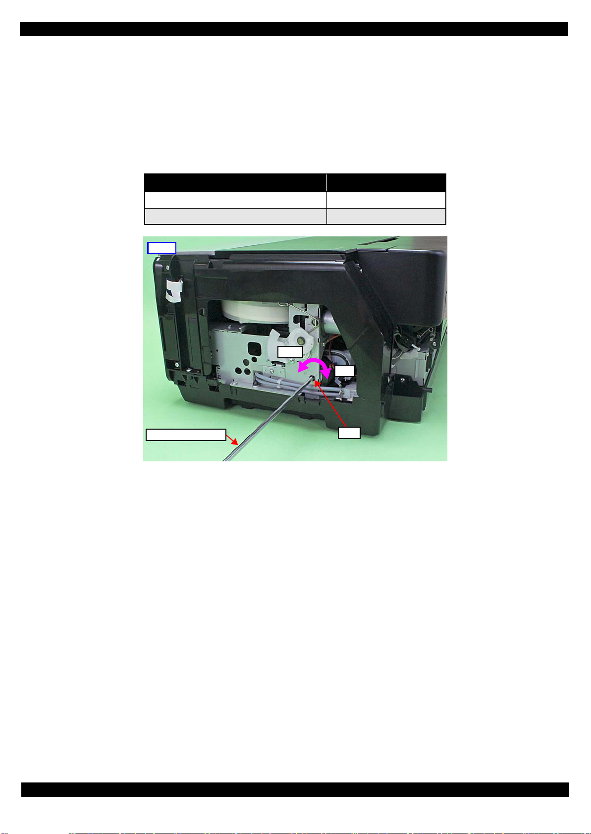
Right
Hole
Phillips screwdriver
CW
CCW
1.1.3 Precautions before Disassembling
Unlocking the carriage
Unlock the carriage by following the procedure below.
1. Remove the Rear Housing, Right Cover, and Right Decoration Plate.
2. Insert a phillips screwdriver into the hole of the frame on the right side of the printer, and rotate the white
shaft of the Ink System.
Table 1-1. Carriage Lock/Unlock
Direction of Rotation Carriage
Clockwise (CW) Locked
Counterclockwise (CCW) Unlocked
Figure 1-1. Unlock the Carriage
Handling the Ink Supply Unit
In order to prevent ink leakage, be careful of the following when handling the Ink Supply Unit.
(See “Ink Supply Unit (p22)” and “CR Contact Module (p22) ” for details.)
Unless otherwise specified in this manual, do not disassemble the Ink Supply Unit any further than specified as an
ASP. Otherwise, replace the Ink Supply Unit with a new one.
Be careful not to damage the film of the ink path.
When disassembling/reassembling the printer, be careful not to apply extra force on the joint part of the ink tube
and I/C Holder Unit, and on that of the ink tube and Ink Selector.
Disassembly/Reassembly Overview 10
Confidential
Page 11
Epson Stylus Photo R3000 Revision A
Front tray lock
Strong tape
Folded end
CR Unit
Strong tape
Attach strong tape with
its unfolded end sticking
out of the printer.
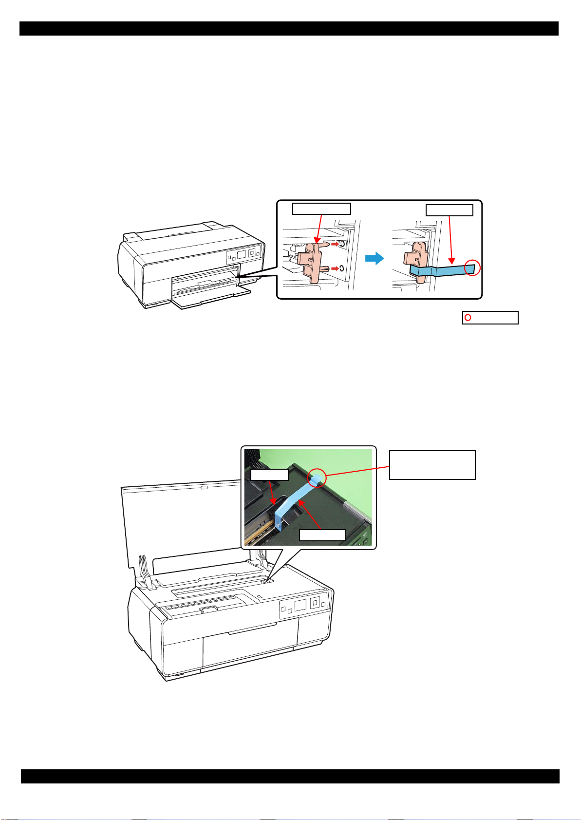
1.1.4 Preparation before Returning the Unit to the User
When returning the printer to the user, make sure to secure the specified points with tapes to avoid damaging the
printer during transport.
Attaching the front tray lock (tape length: 90
2 mm, tape width: 18 mm, fold one end by 5 mm)
Attach the front tray lock and secure it with strong tape as follows.
1. Attach the front tray lock on the position shown in Figure 1-2.
2. Attach the unfolded end of strong tape on the front tray lock as shown in Figure 1-2, and pull the tape and
apply it along the shapes of the Upper Housing Support Assy to secure the front tray lock.
Figure 1-2. Attaching and Securing the Front Tray Lock
Securing the CR Unit (tape length: 220
2 mm, tape width: 18 mm, fold one end by 5 mm)
Secure the CR Unit with strong tape as follows.
1. Open the printer cover and move the CR Unit to its home position.
2. Attach the unfolded end of strong tape on the CR Unit, and pull the tape and apply it along the shapes of
the Upper Housing Assy to the right side of the printer to secure the CR Unit.
Figure 1-3. Securing the CR Unit
Disassembly/Reassembly Overview 11
Confidential
Page 12
Epson Stylus Photo R3000 Revision A
LCD Shield
2
2
(p 15)
Panel Board
2
4
(p 15)
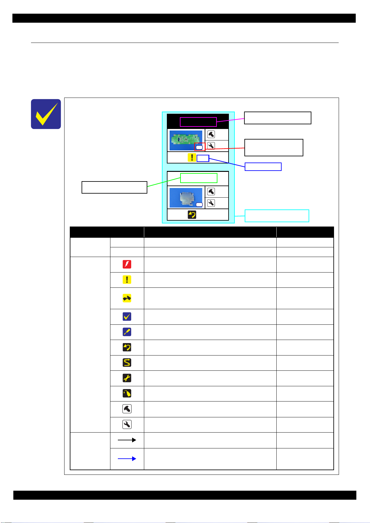
Item Description Reference
Parts/unit name
White-letter
Part/unit supplied as an ASP ---
Black-letter
Part/unit not supplied as an ASP ---
Icon
Indicates a practice or condition that could result in injury or
loss of life if not strictly observed.
Indicates the reference
page in blue-letter
Indicates a practice or condition that could result in damage to,
or destruction of equipment if not strictly observed.
Indicates the reference
page in blue-letter
Indicates the parts that are inevitably broken in the
disassembling procedure, and should be replaced with a new
one for reassembly.
---
Indicates necessary check items in the disassembling/
assembling procedure.
Indicates the reference
page in blue-letter
Indicates supplementary explanation for disassembly is given.
Indicates the reference
page in blue-letter
Indicates particular tasks to keep quality of the units are
required.
Indicates the reference
page in blue-letter
Indicates particular routing of cables is required.
Indicates the reference
page in blue-letter
Indicates particular adjustment(s) is/are required.
Chapter 2 “ Adjustment
(p32)”
Indicates lubrication is required.
Chapter 3 “ Maintenance
(p64)”
Indicates the number of screws securing the parts/units. ---
Indicates the points secured with other than a screw such as a
hook, rib, dowel or the like
---
Arrowed line
Indicates a disassembling procedure. ---
Indicates a removal procedure for a component of a part or
unit which is necessary to remove when proceeding to the
target part.
---
Shows removal/installation
as a unit/assy. is available.
Reference page
Black letters indicate a part/
unit not supplied as an ASP.
Shows the screw types and
the specified torque in the
“Screw type/torque list”.
White letters indicate a part/
unit supplied as an ASP.
1.2 Disassembly/Reassembly Procedures
This section describes procedures for disassembling the parts/units in a flowchart format. For some parts/units,
detailed procedures or precautions are provided (accordingly indicated by icons and cell’s color). Refer to the
explanations in the example chart below and perform an appropriate disassembling and assembling procedure.
(See “1.3 Detailed Disassembly/Reassembly Procedure for each Part/Unit (p19)”.)
For routing cables, see “1.4 Routing FFCs/cables (p29)”.
The example below shows how to see the charts on the following pages.
S12
S4
Disassembly/Reassembly Disassembly/Reassembly Procedures 12
Confidential
Page 13
Epson Stylus Photo R3000 Revision A
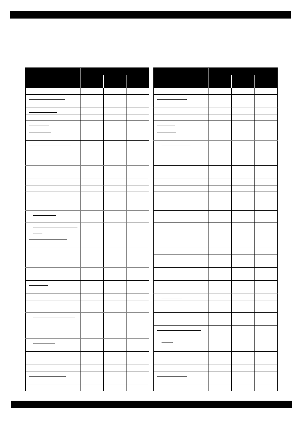
1.2.1 Standard Operation Time for servicing the product (TBD)
The following are the standard operation time for servicing the product. Those are based on the MTTR result
measured using a prototype.
The underlined parts/units are supplied as After Service Parts.
Table 1-2. Standard Operation Time (TBD)
Time (second)
Parts/Unit
Rear Housing CR Relay Board
Paper Support Assy
Stacker Cover Ink Selector
CSIC Terminal
Adjust Printer Cover Printhead Mounting Plate
Left Cover
Right Cover Head FFC
Left Decoration Plate CR Support Plate
Right Decoration Plate
Upper Housing Support
Assy (w/Panel Unit)
Panel Shield Plate CR Unit
Cover Open Sensor PF Frame
Panel Board
LCD Mounting Plate PF Roller
LCD LD Roller Guide
Panel Buttons
(w/OK Button)
OK Button ASF Motor
Panel Cover
Upper Housing Support
Assy
Upper Housing Assy
(w/Upper Printer Cover)
Upper Printer Cover
Holder
Upper Printer Cover
Upper Housing Printer Mechanism
CR Scale
APG
Assy Middle Frame
APG Motor Mist Board Assy
Driven Pulley Mist Board
Wireless LAN Module
Assy
Wireless LAN Module
Board Assy
(Main Board/Power
Supply Board)
Main Board
Power Supply Board Star Wheel Assy
PF Motor Stopper Tray Unit
PF Encoder Assy
ASF Relay Board Ink Tube Holder
CR Contact Module Front Tray Assy
Roll Paper Guide Assy Tray Support Assy
CR Cover Front Tray
Replace-
ment
Adjust-
ment
Total
Parts/Unit
Ink Supply Unit
I/C Holder Unit
Printhead
Ink Tube Guide
CR Guide Plate
Rear Paper Guide
ASF
Assy
Paper Guide
(under ASF Assy)
Shield Plate Assy Upper
Main Board
Release Holder Assy
PE Detector Assy
CR Motor
Release Flag Assy
Upper Paper Guide Assy
Lower Paper Guide
Mist Board Cable Holder
Lower Frame
Ink System
Front Paper Guide Assy
Porous Pad Front Paper
Guide
Tray Detector
Replace-
ment
Time (second)
Adjust-
ment
Total
Disassembly/Reassembly Disassembly/Reassembly Procedures 13
Confidential
Page 14

Epson Stylus Photo R3000 Revision A
Table 1-2. Standard Operation Time (TBD)
Time (second)
Parts/Unit
Lower Housing Assy PictBridge Holder Assy
Waste Ink Pad
Lower Paper Guide Ink
Pad Tray
Stacker Assy Lower Housing
Replace-
ment
Adjust-
ment
Total
Parts/Unit
Foot
Waste Ink Tube
Decomp Pump Assy
Replace-
ment
Time (second)
Adjust-
ment
Total
Disassembly/Reassembly Disassembly/Reassembly Procedures 14
Confidential
Page 15
Epson Stylus Photo R3000 Revision A
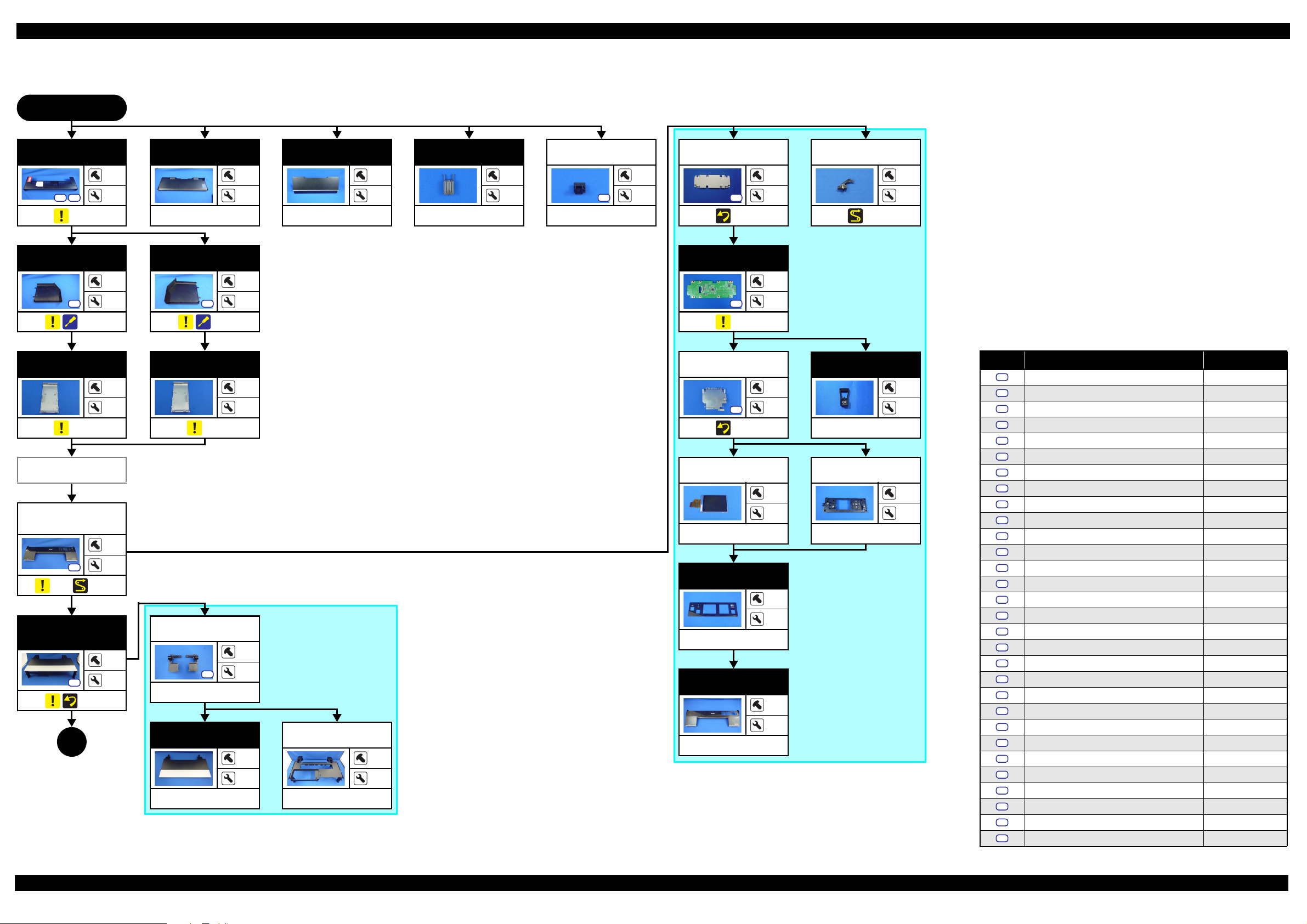
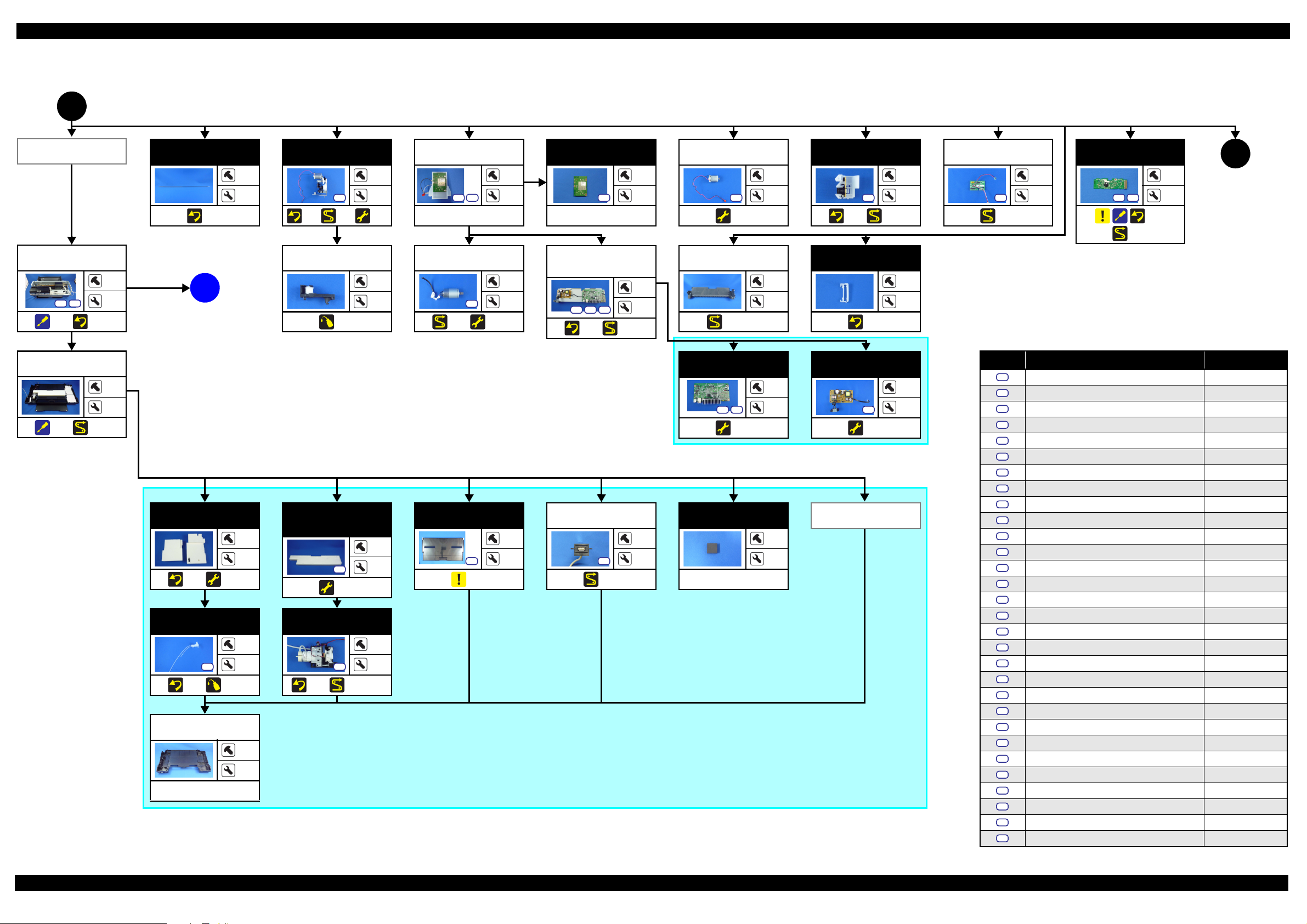
1.2.2 Disassembly/Reassembly Flowchart
1.2.2.1 Housing Part
START
Rear Housing
S9
S20
(p 19)
Left Cover
S5
(p 19)
Left
Decoration Plate
(p 19)
Adjust Printer
Cover
Upper Housing
Support Assy
(w/Panel Unit)
S6
(p 19) (p 29)
Upper Housing
Assy (w/Upper
Printer Cover)
S13
(p 19)
1
(p 16)
Paper Support
Assy
3
12
---
---
4
Stacker Cover
---
CSIC Terminal
---
2
---
---
2
Adjust Printer
Cover
S5
---
1
---
Right Cover
1
4
S5
(p 19)
1
4
Panel Shield
Plate
S12
(p 20)
Panel Board
S12
(p 20)
10
2
2
4
Cover Open
Sensor
---
2
(p 29)
Screw type/torque list
Right
Decoration Plate
---
3
(p 19)
---
3
LCD Mounting
Plate
S4
(p 20)
LCD
---
OK Button
2
2
---
Panel Buttons
(w/OK Button)
---
---
---
---
2
---
4
4
14
Panel Cover
---
Upper Printer
Cover Holder
4
---
S12
---
4
10
---
Upper Housing
Support Assy
---
---
Upper Printer
Cover
---
Upper Housing
---
---
---
---
---
---
---
Symbol Screw type Torque
S1
C.B.P-TITE SCREW,2.5X8,F/ZN-3C 2.5 0.5 kgf·cm
S2
C.B.P-TITE SCREW,2.5X8,F/ZN-3C 3.5 0.5 kgf·cm
S3
C.B.P-TITE SCREW,2X6,F/ZN-3C 2.0
S4
C.B.P-TITE SCREW,2X6,F/ZN-3C 3.0 1.0 kgf·cm
S5
C.B.P-TITE SCREW,3X10,F/ZB-3C 6.0
S6
C.B.P-TITE SCREW,3X10,F/ZN-3C 6.0 1.0 kgf·cm
S7
C.B.P-TITE SCREW,3X18,F/ZN-3C 6.0
S8
C.B.P-TITE SCREW,3X6,F/ZN-3C 4.0 0.5 kgf·cm
S9
C.B.P-TITE SCREW,3X8,F/ZB-3C 6.0
S10
C.B.P-TITE SCREW,3X8,F/ZN-3C 4.0 0.5 kgf·cm
S11
C.B.P-TITE SCREW,3X8,F/ZN-3C 5.0
S12
C.B.P-TITE SCREW,3X8,F/ZN-3C 6.0 1.0 kgf·cm
S13
C.B.P-TITE SCREW,4X8,F/ZN-3C 8.0
S14
C.B.SCREW,2.5X14,F/ZN-3C 3.0 1.0 kgf·cm
S15
C.B.SCREW,2.5X6,F/ZN-3C 3.5
S16
C.B.SCREW,3X4,F/ZN-3C 4.0 0.5 kgf·cm
S17
C.B.SCREW,3X6,F/ZN-3C 8.0
S18
C.B.S-TITE SCREW,2.5X6,F/ZN-3C 4.0 0.5 kgf·cm
S19
C.B.S-TITE SCREW,3X4,F/ZN-3C 8.0
S20
C.B.S-TITE SCREW,3X6,F/ZN-3C 6.0 1.0 kgf·cm
S21
C.B.S-TITE SCREW,3X6,F/ZN-3C 8.0
S22
C.B.S-TITE SCREW,3X8,F/ZN-3C 8.0 1.0 kgf·cm
S23
C.B.S-TITE(P2)SCREW,3X10,F/ZN-3C 6.0
S24
C.B.S-TITE(P4)SCREW,3X6,F/ZN-3C 8.0 1.0 kgf·cm
S25
C.B.S-TITE(P4)SCREW,3X8,F/ZN-3C 5.0
S26
C.B.S-TITE(P4)SCREW,3X8,F/ZN-3C 8.0 1.0 kgf·cm
S27
C.C.SCREW,3X4,F/ZN-3C 4.0
S28
C.P.SCREW,2.6X3,F/ZN-3C 3.0 0.5 kgf·cm
S29
C.P.SCREW,3X10,F/ZN-3C 6.0
S30
C.P.SCREW,3X4,F/ZN-3C 6.0 1.0 kgf·cm
0.5 kgf·cm
1.0 kgf·cm
1.0 kgf·cm
1.0 kgf·cm
1.0 kgf·cm
1.0 kgf·cm
0.5 kgf·cm
1.0 kgf·cm
1.0 kgf·cm
1.0 kgf·cm
1.0 kgf·cm
1.0 kgf·cm
0.5 kgf·cm
1.0 kgf·cm
Flowchart 1-1. Disassembly Flowchart of Housing Part
Disassembly/Reassembly Disassembly/Reassembly Flowchart 15
Confidential
Page 16
Epson Stylus Photo R3000 Revision A
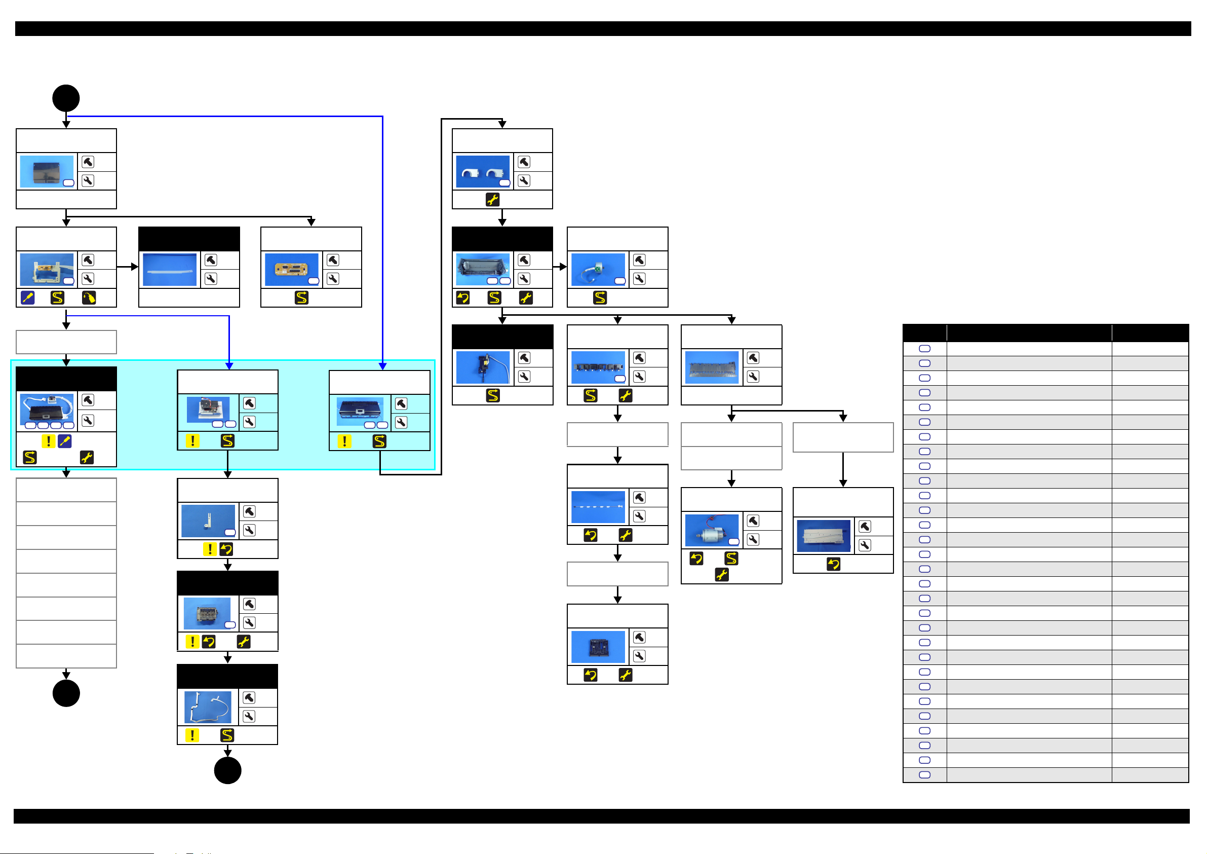
1.2.2.2 Printer Mechanism Part
(p 15)
1
Wireless LAN
Module Assy
Printer
Mechanism
S13 S23
(p 21) (p 21)
Lower Housing
(p 21) (p 29)
*
Assy
CR Scale
---
3
(p 20)
(p 20)
APG Assy
S21
(p 30)
---
(p 32)
3
Driven Pulley
6
A
2
---
---
(p 18)
(p 66)
Wireless LAN
Module Assy
S5
S20
---
PF Motor
S27
(p 30) (p 32)
3
---
2
---
Wireless LAN
Module
S12
---
Board Assy (Main
Board/Power
Supply Board)
S20 S23 S29
(p 28) (p 30)
APG Motor
3
2
S28
(p 32)
Roll Paper
Guide Assy
7
---
(p 29, p 30)
2
---
---
2
PF Encoder Assy
S22
(p 27) (p 30)
Ink Tube Holder
(p 20)
1
4
---
6
ASF Relay
Board
S12
(p 30)
CR Contact
Module
1
---
S21
S7
(p 22)
(p 30)
13
9
2
(p 17)
Screw type/torque list
*: The Printer Mechanism in this flowchart is not the one established as an ASP. The Printer Mechanism as an ASP excludes the
Main Board
following parts from the Printer Mechanism in this flowchart. When replacing the Printer Mechanism specified as an ASP, adjustments
---
---
are required. See Chapter 2 “ Adjustment (p32)” for details.
• ASF Assy
• LD Roller Guide
• Board Assy (Main Board/Power Supply Board)
• Head FFC
•Printhead
• Printhead Mounting Plate
Waste Ink Pad
Lower Paper
Guide Ink Pad
Tra y
---
---
S12
(p 20) (p 32)
Waste Ink Tube
(p 32)
Decomp Pump
Assy
1
S12
(p 20) (p 66)
---
S6
(p 20) (p 29, p 30)
4
• CR Support Plate
• CR Cover
• Ink Supply Unit
• Ink Tube Holder
S20 S30
(p 32)
---
• Paper Guide (under ASF Assy)
• Shield Plate Assy Upper Main Board
Stacker Assy
1
---
S6
(p 19)
4
---
PictBridge
Holder Assy
S6
(p 29)
2
---
Foot
---
---
---
3
---
Power Supply
Board
S20
(p 32)
Stacker Co ve r
4
---
Lower Housing
---
---
---
Symbol Screw type Torque
S1
C.B.P-TITE SCREW,2.5X8,F/ZN-3C 2.5 0.5 kgf·cm
S2
C.B.P-TITE SCREW,2.5X8,F/ZN-3C 3.5 0.5 kgf·cm
S3
C.B.P-TITE SCREW,2X6,F/ZN-3C 2.0
S4
C.B.P-TITE SCREW,2X6,F/ZN-3C 3.0 1.0 kgf·cm
S5
C.B.P-TITE SCREW,3X10,F/ZB-3C 6.0
S6
C.B.P-TITE SCREW,3X10,F/ZN-3C 6.0 1.0 kgf·cm
S7
C.B.P-TITE SCREW,3X18,F/ZN-3C 6.0
S8
C.B.P-TITE SCREW,3X6,F/ZN-3C 4.0 0.5 kgf·cm
S9
C.B.P-TITE SCREW,3X8,F/ZB-3C 6.0
S10
C.B.P-TITE SCREW,3X8,F/ZN-3C 4.0 0.5 kgf·cm
S11
C.B.P-TITE SCREW,3X8,F/ZN-3C 5.0
S12
C.B.P-TITE SCREW,3X8,F/ZN-3C 6.0 1.0 kgf·cm
S13
C.B.P-TITE SCREW,4X8,F/ZN-3C 8.0
S14
C.B.SCREW,2.5X14,F/ZN-3C 3.0 1.0 kgf·cm
S15
C.B.SCREW,2.5X6,F/ZN-3C 3.5
S16
C.B.SCREW,3X4,F/ZN-3C 4.0 0.5 kgf·cm
S17
C.B.SCREW,3X6,F/ZN-3C 8.0
S18
C.B.S-TITE SCREW,2.5X6,F/ZN-3C 4.0 0.5 kgf·cm
S19
C.B.S-TITE SCREW,3X4,F/ZN-3C 8.0
S20
C.B.S-TITE SCREW,3X6,F/ZN-3C 6.0 1.0 kgf·cm
S21
C.B.S-TITE SCREW,3X6,F/ZN-3C 8.0
S22
C.B.S-TITE SCREW,3X8,F/ZN-3C 8.0 1.0 kgf·cm
S23
C.B.S-TITE(P2)SCREW,3X10,F/ZN-3C 6.0
S24
C.B.S-TITE(P4)SCREW,3X6,F/ZN-3C 8.0 1.0 kgf·cm
S25
C.B.S-TITE(P4)SCREW,3X8,F/ZN-3C 5.0
S26
C.B.S-TITE(P4)SCREW,3X8,F/ZN-3C 8.0 1.0 kgf·cm
S27
C.C.SCREW,3X4,F/ZN-3C 4.0
S28
C.P.SCREW,2.6X3,F/ZN-3C 3.0 0.5 kgf·cm
S29
C.P.SCREW,3X10,F/ZN-3C 6.0
S30
C.P.SCREW,3X4,F/ZN-3C 6.0 1.0 kgf·cm
0.5 kgf·cm
1.0 kgf·cm
1.0 kgf·cm
1.0 kgf·cm
1.0 kgf·cm
1.0 kgf·cm
0.5 kgf·cm
1.0 kgf·cm
1.0 kgf·cm
1.0 kgf·cm
1.0 kgf·cm
1.0 kgf·cm
0.5 kgf·cm
1.0 kgf·cm
Flowchart 1-2. Disassembly Flowchart of Printer Mechanism Part (1)
Disassembly/Reassembly Disassembly/Reassembly Flowchart 16
Confidential
Page 17
Epson Stylus Photo R3000 Revision A
(p 16)
2
CR Cover
S20
---
CR Support
Plate
S12
(p 21) (p 29)
Wireless LAN
Module Assy
Ink Supply Unit
S1
S15 S21 S22
(p 22)
(p 26, p 29, p 30)
Printhead
Mounting Plate
Print head
Head FFC
CR Scale
LD Roller Guide
ASF Assy
Lower Housing
Assy
Lower Paper
Guide
4
(p 18)
(p 66)
(p 32)
LD Roller Guide
1
2
Ink Tube Guide
4
7
---
---
3
CR Relay Board
S20
(p 29)
2
---
(p 24)
S17
(p 32)
ASF Assy
S21 S26
(p 30)
(p 32)
2
4
ASF Motor
4
2
S12
(p 29, p 30)
2
---
Screw type/torque list
PE Detector Assy
---
Ink Selector*
5
---
S1
S15
2
---
I/C Holder Unit*
S21 S22
3
(p 29)
---
4
Release Holder
Assy
S21
(p 29) (p 32)
3
3
APG Assy
(p 10) (p 26, p 29)
(p 10) (p 26, p 30)
Paper Guide
(under ASF Assy)
---
APG Assy
---
2
Board Assy (Main
Board/Power
Supply Board)
Driven Pulley
Release Flag
Printhead
Mounting Plate
S2
(p 21)
Print head
S2
(p 21) (p 32)
1
---
3
---
Assy
(p 23) (p 32)
PE Detector Assy
Upper Paper
Guide Assy
---
4
CR Motor
S16
(p 23) (p 29, p 30)
(p 32)
2
---
Shield Plate Assy
Upper Main
Board
S21
(p 28)
---
2
Head FFC
(p 23) (p 32)
---
---
(p 26) (p 29, p 30)
*: The Ink Selector and I/C Holder Unit are the parts of the Ink Supply Unit. However, if the disassembly is
3
(p 18)
Flowchart 1-3. Disassembly Flowchart of Printer Mechanism Part (2)
not for replacement of the Ink Supply Unit, it is faster that only either of the Ink Selector or I/C Holder
Unit is removed to proceed the next step. Therefore, they are listed in this flowchart separately.
Symbol Screw type Torque
S1
C.B.P-TITE SCREW,2.5X8,F/ZN-3C 2.5 0.5 kgf·cm
S2
C.B.P-TITE SCREW,2.5X8,F/ZN-3C 3.5 0.5 kgf·cm
S3
C.B.P-TITE SCREW,2X6,F/ZN-3C 2.0
S4
C.B.P-TITE SCREW,2X6,F/ZN-3C 3.0 1.0 kgf·cm
S5
C.B.P-TITE SCREW,3X10,F/ZB-3C 6.0
S6
C.B.P-TITE SCREW,3X10,F/ZN-3C 6.0 1.0 kgf·cm
S7
C.B.P-TITE SCREW,3X18,F/ZN-3C 6.0
S8
C.B.P-TITE SCREW,3X6,F/ZN-3C 4.0 0.5 kgf·cm
S9
C.B.P-TITE SCREW,3X8,F/ZB-3C 6.0
S10
S11
S12
3
2
S13
S14
S15
S16
S17
S18
S19
S20
S21
S22
S23
S24
S25
S26
S27
S28
S29
S30
C.B.P-TITE SCREW,3X8,F/ZN-3C 4.0 0.5 kgf·cm
C.B.P-TITE SCREW,3X8,F/ZN-3C 5.0
C.B.P-TITE SCREW,3X8,F/ZN-3C 6.0 1.0 kgf·cm
C.B.P-TITE SCREW,4X8,F/ZN-3C 8.0
C.B.SCREW,2.5X14,F/ZN-3C 3.0 1.0 kgf·cm
C.B.SCREW,2.5X6,F/ZN-3C 3.5
C.B.SCREW,3X4,F/ZN-3C 4.0 0.5 kgf·cm
C.B.SCREW,3X6,F/ZN-3C 8.0
C.B.S-TITE SCREW,2.5X6,F/ZN-3C 4.0 0.5 kgf·cm
C.B.S-TITE SCREW,3X4,F/ZN-3C 8.0
C.B.S-TITE SCREW,3X6,F/ZN-3C 6.0 1.0 kgf·cm
C.B.S-TITE SCREW,3X6,F/ZN-3C 8.0
C.B.S-TITE SCREW,3X8,F/ZN-3C 8.0 1.0 kgf·cm
C.B.S-TITE(P2)SCREW,3X10,F/ZN-3C 6.0
C.B.S-TITE(P4)SCREW,3X6,F/ZN-3C 8.0 1.0 kgf·cm
C.B.S-TITE(P4)SCREW,3X8,F/ZN-3C 5.0
C.B.S-TITE(P4)SCREW,3X8,F/ZN-3C 8.0 1.0 kgf·cm
C.C.SCREW,3X4,F/ZN-3C 4.0
C.P.SCREW,2.6X3,F/ZN-3C 3.0 0.5 kgf·cm
C.P.SCREW,3X10,F/ZN-3C 6.0
C.P.SCREW,3X4,F/ZN-3C 6.0 1.0 kgf·cm
0.5 kgf·cm
1.0 kgf·cm
1.0 kgf·cm
1.0 kgf·cm
1.0 kgf·cm
1.0 kgf·cm
0.5 kgf·cm
1.0 kgf·cm
1.0 kgf·cm
1.0 kgf·cm
1.0 kgf·cm
1.0 kgf·cm
0.5 kgf·cm
1.0 kgf·cm
Disassembly/Reassembly Disassembly/Reassembly Flowchart 17
Confidential
Page 18
Epson Stylus Photo R3000 Revision A
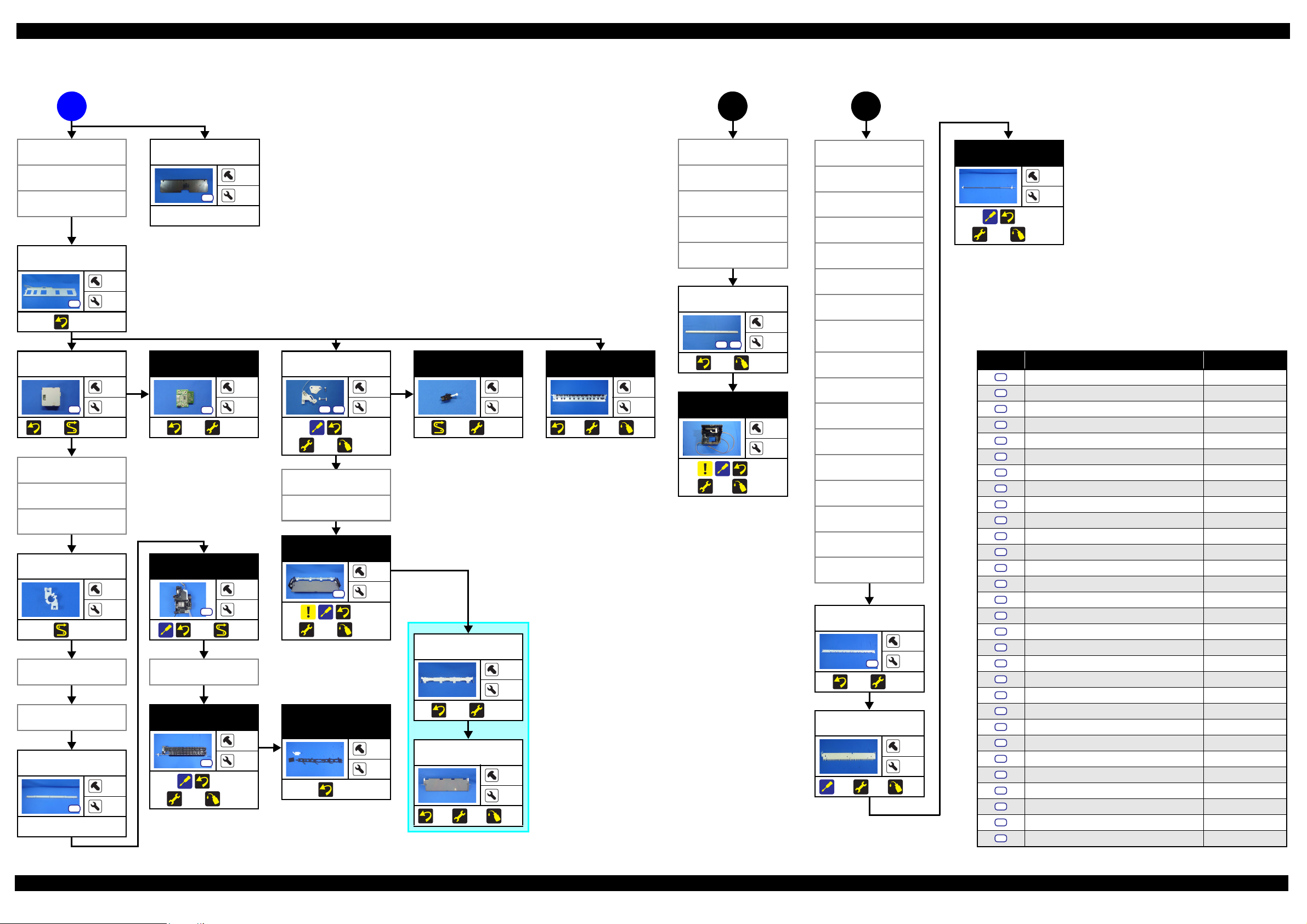
(p 16)
A
CR Cover
CR Support
Plate
Ink Supply Unit
Middle Frame
S21
(p 23)
Mist Board Assy
S21
(p 27) (p 30, p 31)
LD Roller Guide
ASF Assy
Paper Guide
(under ASF Assy)
Mist Board
Cable Holder
(p 31)
Lower Paper
Guide
Stopper Tray
Unit
Lower Frame
S21
---
(p 17)
3
Lower Paper
Guide
S26
---
1
3
APG Assy
Driven Pulley
CR Scale
I/C Holder Unit
APG Assy
Driven Pulley
Middle Frame
CR Guide Plate
Middle Frame
6
10
CR Guide Plate
5
S24S18
Mist Board
1
1
S20
(p 27) (p 32)
2
---
Stopper Tray
Unit
S21S10
(p 25)
(p 32) (p 66)
Tray Detector
2
---
(p 30) (p 32)
---
4
Star Wheel Assy
(p 26)
(p 32)
---
(p 66)
2
Star Wheel Assy
Lower Paper
Guide
(p 21) (p 67)
CR Unit
(p 24)
(p 32)
(p 67)
---
---
---
Front Tray Assy
Ink System
---
2
S21
(p 24) (p 30)
4
2
S8
(p 25)
(p 32) (p 67)
Star Wheel Assy
3
---
Tray Support
Assy
---
---
Front Paper
Guide Assy
1
S11
4
2
(p 26)
(p 32) (p 68)
---
Porous Pad
Front Paper
Guide
(p 26)
---
---
(p 25) (p 32)
Front Tray
(p 25)
(p 32)
---
---
(p 67)
Mist Board Assy
Mist Board
Cable Holder
Paper Guide
(under ASF
Stopper Tray
Lower Frame
Ink System
Star Wheel Assy
Front Paper
Guide Assy
Release Holder
Release Flag
PE Detector Assy
Upper Paper
Guide Assy
PF Frame
(p 23) (p 32)
Rear Paper
(p 23)
4
CR Unit
Assy)
Unit
Assy
Assy
S19
Guide
(p 32)
(p 17)
(p 66)
PF Roller
---
---
(p 27)
(p 32) (p 66)
Screw type/torque list
Symbol Screw type Torque
S1
C.B.P-TITE SCREW,2.5X8,F/ZN-3C 2.5 0.5 kgf·cm
S2
C.B.P-TITE SCREW,2.5X8,F/ZN-3C 3.5 0.5 kgf·cm
S3
C.B.P-TITE SCREW,2X6,F/ZN-3C 2.0
S4
C.B.P-TITE SCREW,2X6,F/ZN-3C 3.0 1.0 kgf·cm
S5
C.B.P-TITE SCREW,3X10,F/ZB-3C 6.0
S6
C.B.P-TITE SCREW,3X10,F/ZN-3C 6.0 1.0 kgf·cm
S7
C.B.P-TITE SCREW,3X18,F/ZN-3C 6.0
S8
C.B.P-TITE SCREW,3X6,F/ZN-3C 4.0 0.5 kgf·cm
S9
C.B.P-TITE SCREW,3X8,F/ZB-3C 6.0
S10
S11
S12
S13
S14
S15
S16
6
---
---
3
S17
S18
S19
S20
S21
S22
S23
S24
S25
S26
S27
S28
S29
S30
C.B.P-TITE SCREW,3X8,F/ZN-3C 4.0 0.5 kgf·cm
C.B.P-TITE SCREW,3X8,F/ZN-3C 5.0
C.B.P-TITE SCREW,3X8,F/ZN-3C 6.0 1.0 kgf·cm
C.B.P-TITE SCREW,4X8,F/ZN-3C 8.0
C.B.SCREW,2.5X14,F/ZN-3C 3.0 1.0 kgf·cm
C.B.SCREW,2.5X6,F/ZN-3C 3.5
C.B.SCREW,3X4,F/ZN-3C 4.0 0.5 kgf·cm
C.B.SCREW,3X6,F/ZN-3C 8.0
C.B.S-TITE SCREW,2.5X6,F/ZN-3C 4.0 0.5 kgf·cm
C.B.S-TITE SCREW,3X4,F/ZN-3C 8.0
C.B.S-TITE SCREW,3X6,F/ZN-3C 6.0 1.0 kgf·cm
C.B.S-TITE SCREW,3X6,F/ZN-3C 8.0
C.B.S-TITE SCREW,3X8,F/ZN-3C 8.0 1.0 kgf·cm
C.B.S-TITE(P2)SCREW,3X10,F/ZN-3C 6.0
C.B.S-TITE(P4)SCREW,3X6,F/ZN-3C 8.0 1.0 kgf·cm
C.B.S-TITE(P4)SCREW,3X8,F/ZN-3C 5.0
C.B.S-TITE(P4)SCREW,3X8,F/ZN-3C 8.0 1.0 kgf·cm
C.C.SCREW,3X4,F/ZN-3C 4.0
C.P.SCREW,2.6X3,F/ZN-3C 3.0 0.5 kgf·cm
C.P.SCREW,3X10,F/ZN-3C 6.0
C.P.SCREW,3X4,F/ZN-3C 6.0 1.0 kgf·cm
0.5 kgf·cm
1.0 kgf·cm
1.0 kgf·cm
1.0 kgf·cm
1.0 kgf·cm
1.0 kgf·cm
0.5 kgf·cm
1.0 kgf·cm
1.0 kgf·cm
1.0 kgf·cm
1.0 kgf·cm
1.0 kgf·cm
0.5 kgf·cm
1.0 kgf·cm
Flowchart 1-4. Disassembly Flowchart of Printer Mechanism Part (3)
Disassembly/Reassembly Disassembly/Reassembly Flowchart 18
Confidential
Page 19
Epson Stylus Photo R3000 Revision A
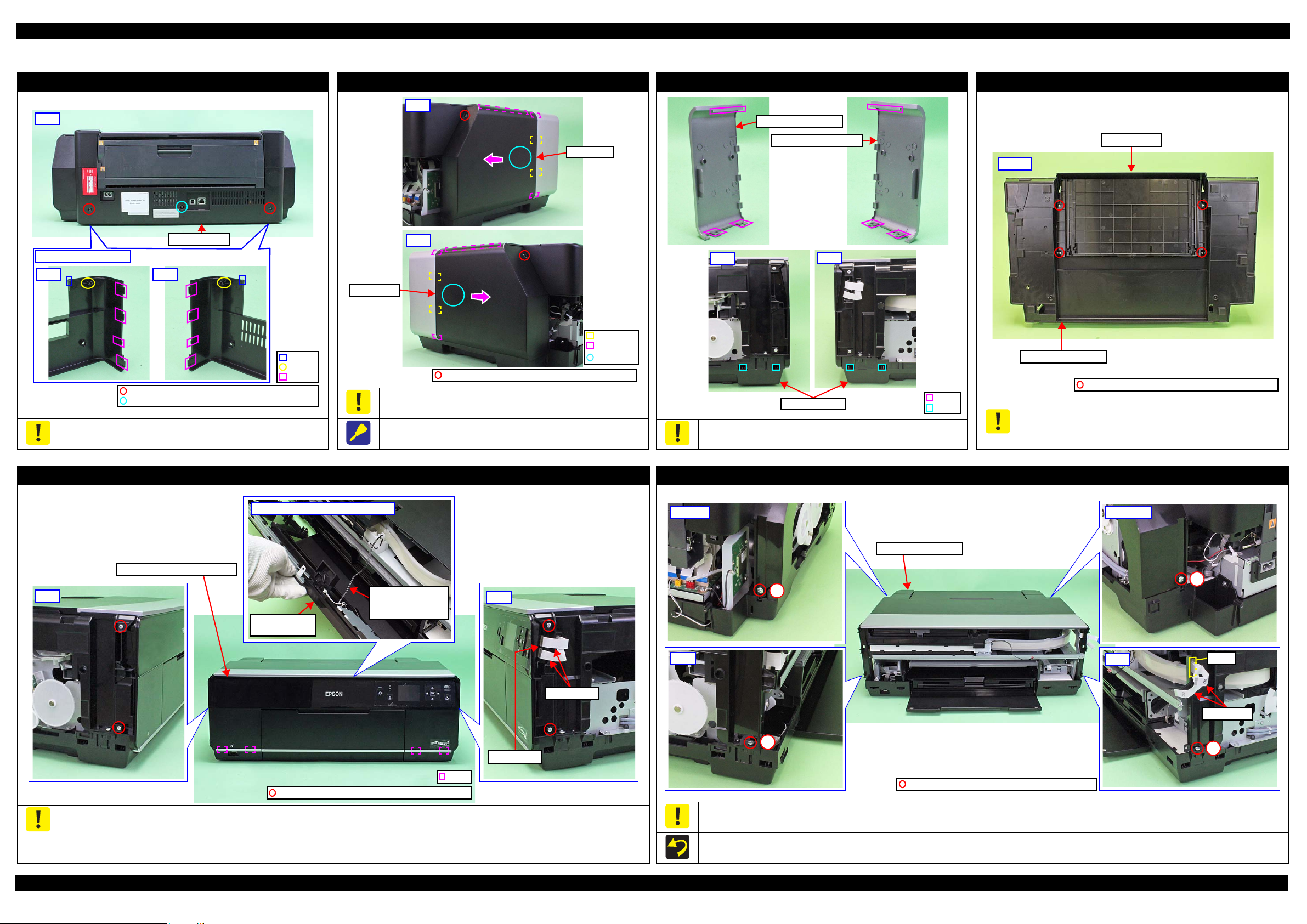
Rear Housing
Left Right
Rear
C.B.S-TITE SCREW,3X6,F/ZN-3C (6 ± 1 kgf·cm)
C.B.P-TITE SCREW,3X8,F/ZB-3C (6 ± 1 kgf·cm)
Back of Rear Housing
Dowel
Rib
Hook
Rib
Hook
Section A
Left Cover
Right
Left
Right Cover
C.B.P-TITE SCREW,3X10,F/ZB-3C (6 ± 1 kgf·cm)
Left
Right
Left Decoration Plate
Right Decoration Plate
Hook
Rib
Lower Housing
C.B.P-TITE SCREW,3X10,F/ZN-3C (6 ± 1 kgf·cm)
Bottom
Stacker Assy
Lower Housing Assy
Hook
C.B.P-TITE SCREW,3X10,F/ZN-3C (6 1 kgf·cm)
Upper Housing Support Assy
Left
I/C Holder Unit
Cover Open Sensor
Cable
Back of Upper Housing Support Assy
Upper Housing
Support Assy
Panel FFCs
Panel Board
Right
2
3
4
Panel FFCs
Right
Hole
1
Left
Upper Housing Assy
C.B.P-TITE SCREW,4X8,F/ZN-3C (8 ± 1 kgf·cm)
Rear rightRear left
1.3 Detailed Disassembly/Reassembly Procedure for each Part/Unit
Rear Housing
Be careful not to damage the hooks (x2), dowels (x2) and ribs (x8)
that secure the Rear Housing.
Left / Right Cover
Remove the Left/Right Cover carefully not to damage the hooks
(x2 each) and ribs (x3 each) that secure the Left/Right Cover.
When removing the Left/Right Cover, slide it in the direction of the
arrow shown above while slightly pushing the section A.
Left / Right Decoration Plate
Be careful not to damage the ribs (x3 each) that secure the Left/
Right Decoration Plate and hooks (x4) of the Lower Housing.
Stacker Assy
Be careful for ink to flow out then because if tilting is too soon after
the initial ink charge or a similar situation, the ink still on the Waste
Ink Pad which is not yet absorbed flows over out of the printer.
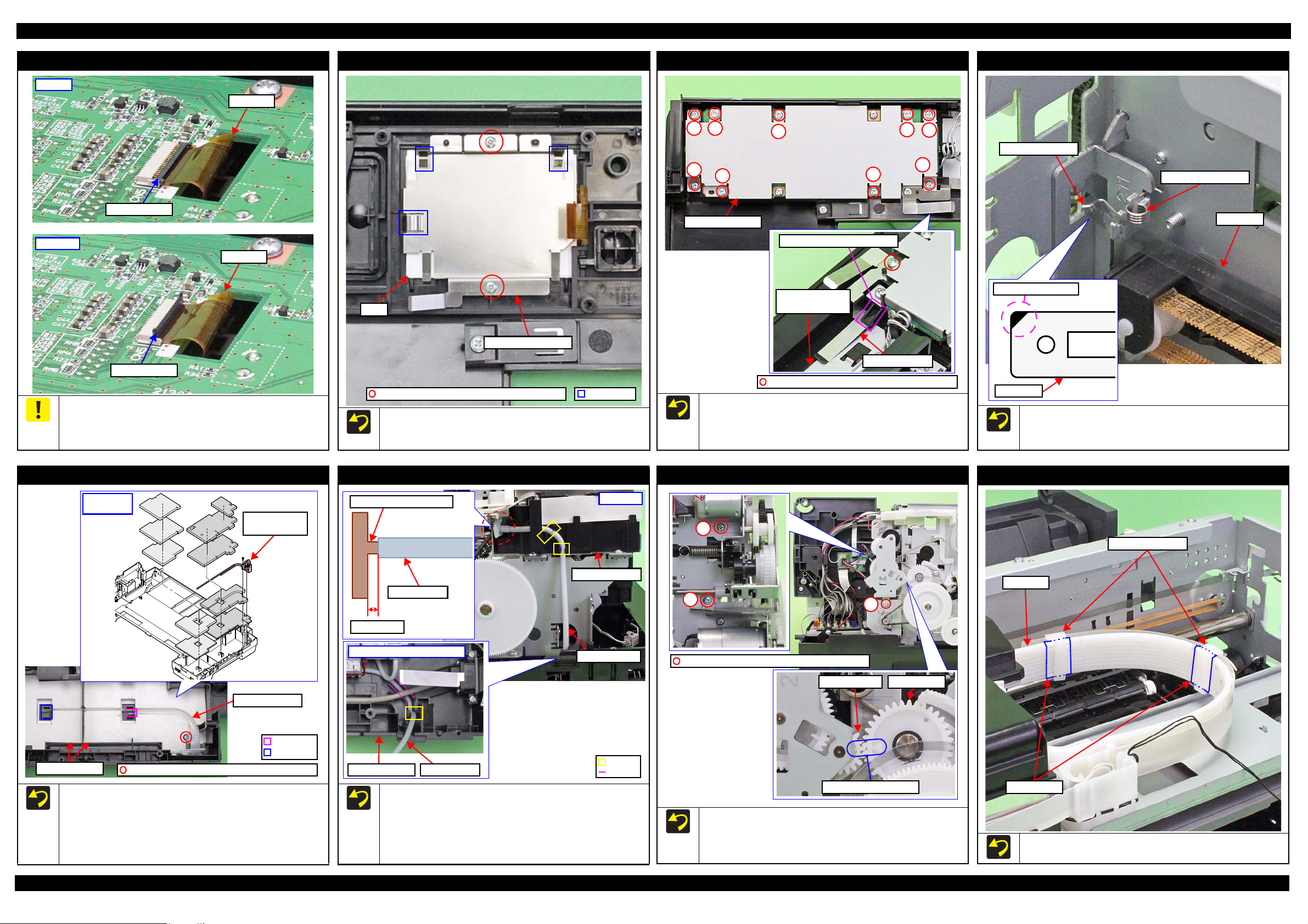
Upper Housing Support Assy (w/Panel Unit)
Disconnect the Panel FFCs (x2) from the connectors on the Panel Board before removing the Upper Housing Support Assy.
Be careful not to damage the hooks (x4) that secure the Upper Housing Support Assy.
Be careful to remove the Upper Housing Support Assy because the I/C Holder Unit Cover Open Sensor Cable is connected to the sensor on the
Disassembly/Reassembly Detailed Disassembly/Reassembly Procedure for each Part/Unit 19
back of the Upper Housing Support Assy.
Pull out the Panel FFCs(x2) from the hole of the Upper Housing Assy before removing the Upper Housing Assy.
Tighten the screws in the order indicated in the figure above.
Upper Housing Assy (w/Printer Cover Upper)
Confidential
Page 20
Epson Stylus Photo R3000 Revision A
Locked
LCD FPC
Connector Lock
Unlocked
LCD FPC
Connector Lock
Protrusion
LCD Mounting Plate
LCD
C.B.P-TITE SCREW,2X6,F/ZN-3C (3 ± 1 kgf·cm)
1
2
3
4
5
6
7
8
9
Panel Shield Plate
C.B.P-TITE SCREW,3X8,F/ZN-3C (6 ± 1 kgf·cm)
Grounding Plate
Protrusion of Panel Buttons
Housing Support
reinforcing plate
CR Scale
Torsion Spring, 0.39
CR Scale
Black triangle mark
Longer spring leg
Section B
Section A
Waste Ink Tube
/ Tube Holder
Waste Ink Pads
C.B.P-TITE SCREW,3X8,F/ZN-3C (6 ± 1 kgf·cm)
Waste Ink Tube
Installation
order
1 mm or less
Joint for Decomp Tube
Decomp Tube
Hook
Left inside of Lower Housing
Decomp Tube
I/C Holder Unit
Lower Housing
Decomp Tube
Groove
Left side
PG Cam LeftSpur Gear,14.4
Align triangle marks.
3
C.B.S-TITE SCREW,3X6,F/ZN-3C(8 1kgf·cm)
1
2
Ink Tube Holders
Ink Tube
Acetate Tape
Panel Board
LCD Mounting Plate
Panel Shield Plate
CR Scale
Before disconnecting the LCD FPC, unlock the connector lock that
secures the LCD FPC. When connecting the LCD FPC, make sure
to insert the LCD FPC into the connector to the full and secure it
with the connector lock.
Waste Ink Tube / Waste Ink Pad
When installing the LCD Mounting Plate, make sure the LCD is
located inside the protrusions (x3) of the LCD Mounting Plate, and
then secure the plate with the screws.
Decomp Pump Assy
Install the Panel Shield Plate under the protrusion of the Panel
Buttons as shown above. Make sure that the plate contacts the
Housing Support reinforcing plate, and secure it with the screw.
Tighten the screws in the order indicated in the figure above.
APG Assy
Attach the CR Scale to the spring leg with the black triangle
mark upward on the left side of the printer.
Attach the Torsion Spring, 0.39 as shown above.
Ink Tube Holder
Disassembly/Reassembly Detailed Disassembly/Reassembly Procedure for each Part/Unit 20
When installing the Waste Ink Tube/Waste Ink Pads (x10),
confirm the shapes of them and install them in the order shown
above.
When installing the Waste Ink Tube, route it through the
groove of the Waste Ink Pads, and insert the end of the shorter
tube to the section A and longer one to the section B.
When connecting the Decomp Tube to the joint of the I/C
Holder Unit, make sure the gap between the end of the Decomp
Tube to the base of the joint is 1 mm or less, and then secure
the tube with the hooks (x2).
Route the Decomp Tube through the groove of the Lower
Housing and secure the tube with the hook.
When installing the APG Assy, align the marks on the Spur
Gear,14.4 and PG Cam Left to match their phases as shown
above.
Tighten the screws in the order indicated in the figure above.
When installing the Ink Tube Holders (x2), install them on the
locations where the acetate tape (x2) is attached on the Ink Tube.
Confidential
Page 21
Epson Stylus Photo R3000 Revision A
Front left
Connector of Stopper Tray
Sensor Relay Cable
Rear left
Stopper Tray Sensor Relay Cable
PictBridge Holder Assy Cable
Decomp Pump Motor Cable
Left
Decomp Tube
I/C Holder
Unit
Right
Ink System Tube
Waste Ink Tube
Lower Housing Assy
Printer Mechanism
2
3
Right
6
Tube Clamp
C.B.S-TITE(P2)SCREW,3X10,F/ZN-3C
(6 ± 1kgf·cm)
C.B.P-TITE SCREW,4X8,F/ZN-3C
(8 ± 1kgf·cm)
1 mm or less
5 2 mm
Ink System Tubes
Tube Clamps
Tube Holder
Waste Ink Tubes
5
Rear left
4
Upper left
1
Front Left
Ink Tube Holder
Ink Tube Guide
Ink Tube Guide
Cable Holder Front
Positioning hole
and Dowel
Rib
Hook
Cable Holder Front
CR Support Plate
Ink Selector Motor Cable
Ink Selector Sensor Cable
CR Encoder / PW Sensor FFC
Head FFC
Ink Tube Holders
Ink Tube Guide
C.B.P-TITE SCREW,3X8,F/ZN-3C (6 ± 1 kgf·cm)
CR Relay Board
C.B.S-TITE(P4)SCREW,3X6,F/ZN-3C(8 1kgf·cm)
C.B.S-TITE SCREW,2.5X6,F/ZN-3C(4 0.5kgf·cm)
CR Unit
CR Guide Plate
1
23
45
6
2
1
3
CR Unit
Printhead
C.B.P-TITE SCREW,2.5X8,F/ZN-3C(3.5 0.5kgf·cm)
Printhead Mounting Plate
Printer Mechanism (1)
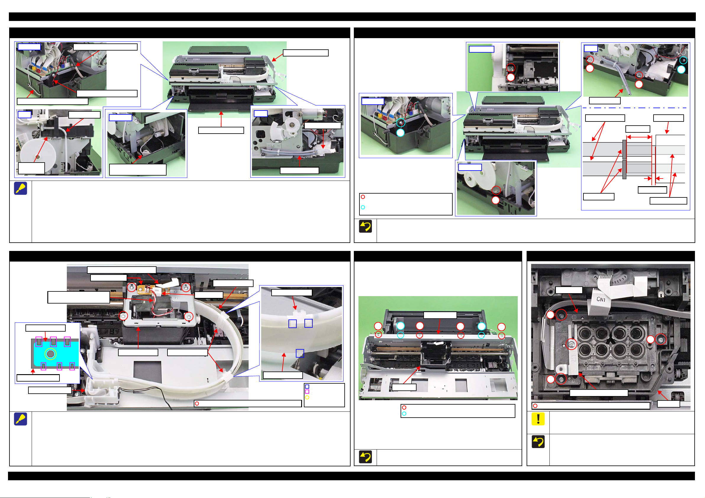
Disconnect the following cables/tubes when removing the Printer Mechanism from the Lower Housing Assy.
Disconnect the following cables from the connector on the Main Board.
• PictBridge Holder Assy Cable (CN3)
• Stopper Tray Sensor Relay Cable (CN1)
• Decomp Pump Motor Cable (CN22)
Disconnect the Decomp Tube.
Disconnect the Ink System Tube from the Waste Ink Tube.
Disconnect the relay connector of the Stopper Tray Sensor Relay Cable.
Printer Mechanism (2)
Tighten the screws in the order indicated in the figure above.
When connecting the Ink System Tube to the Waste Ink Tube, make sure the gap between the end of the Ink System Tube and the Tube Holder is
1 mm or less, and attach the Tube Clamp 5
2 mm from the end of the Ink System Tube.
CR Support Plate
When removing the CR Support Plate, follow the procedure below.
1. Disconnect the following cables/FFCs from the connectors on the CR Relay Board.
• Ink Selector Motor Cable (CN2) • Ink Selector Sensor Cable (CN5)
• Head FFC (CN1) • CR Encoder / PW Sensor FFC (CN6)
2. Remove the screws (x4) that secure the CR Support Plate.
3. Release the hooks (x3 each) of the Ink Tube Holders (x2) and remove the Ink Tube Guide from the Ink Tube Holders (x2).
4. Release the Ink Tube Guide from the ribs (x6) and dowel of the Cable Holder Front, and remove the CR Support Plate.
Disassembly/Reassembly Detailed Disassembly/Reassembly Procedure for each Part/Unit 21
Tighten the screws in the order indicated in the figure above.
CR Guide Plate
Printhead / Printhead Mounting Plate
Do not use the electric screwdriver when installing the Printhead
and/or the Printhead Mounting Plate. Doing so applies extra force
when tightening the screw and affects the platen gap.
When installing the Printhead, follow the procedure below.
1. Temporarily tighten the screws (x3) and loosen them half turn.
2. Press the Printhead to the rear of the printer, and tighten the
screws (x3) in the order indicated in the figure above.
Confidential
Page 22
Epson Stylus Photo R3000 Revision A
Ink tube connection part: Do not disassemble
I/C Holder Unit side
C.B.S-TITE SCREW,3X8,F/ZN-3C
(8 ± 1 kgf·cm)
C.B.S-TITE SCREW,3X6,F/ZN-3C
(8 ± 1 kgf·cm)
C.B.SCREW,2.5X6,F/ZN-3C
(3.5 ± 0.5 kgf·cm)
C.B.P-TITE SCREW,2.5X8,F/ZN-3C
(2.5 ± 0.5 kgf·cm)
Ink Tube Holders
I/C Holder Unit
I/C Holder Unit
Ink Selector side
Hook
Head FFC
Ink Tube Holder
CR Unit
Ink Selector
Ink tube connection part: Do not disassemble
Middle Frame
Head FFC
CSIC FFC
Cable Holder Left
Cable Holder Rear
I/C Holder Unit
Cable Holder Front
I/C Holder Unit Cover
Open Sensor Cable
Middle Frame
C.B.P-TITE SCREW,3X18,F/ZN-3C (6 1kgf·cm)
Inside Ink Box
1
4
2
3
Step 7
Ink Box
Ink Box
Step 9
CR Contact Modules
Ink Box
CSIC FFC
Hook
Rib
Step 8, 9
CR Contact Module Covers
Film
Bottom part of Ink Box: Do not dissemble
Ink Tube connection
Do not loosen screws
Ink Supply Unit
CR Contact Module
To prevent ink leakage, make sure not to separate the ink tubes from the I/C Holder Unit or the Ink Selector by removing the screws (x2). Loosening
the screws even just once will cause ink leakage, therefore, make sure to replace the Ink Supply Unit with a new one.
When removing the Ink Supply Unit, follow the procedure below.
1. Release the Head FFC from the hooks (x2 each) of the Ink Tube Holders (x2). Be careful not to damage the Head FFC then.
2. Remove the screws (x2) that secure the Ink Selector, and remove the Ink Selector from the CR Unit.
3. Disconnect the Decomp Tube from the I/C Holder Unit. (p 21)
4. After removing the Cable Holder Rear and Cable Holder Left from the frame, disconnect the Head FFC and CSIC FFC from the connectors
on the Main Board, and then release the FFCs from the Cable Holder Rear and Cable Holder Left. (p 30)
5. Remove the screws (x3) that secure the I/C Holder Unit, and remove the I/C Holder Unit.
When removing the Ink Selector on the way to the target part, perform only Step 1 and 2 above. Be careful not to contaminate the surroundings
with ink from the Ink Selector when taking subsequent steps.
When removing the I/C Holder Unit on the way to the target part, perform only Step 3 to 5 above. Place the removed I/C Holder Unit on the 0-
digit side of the Middle Frame when taking subsequent steps.
Disassembly/Reassembly Detailed Disassembly/Reassembly Procedure for each Part/Unit 22
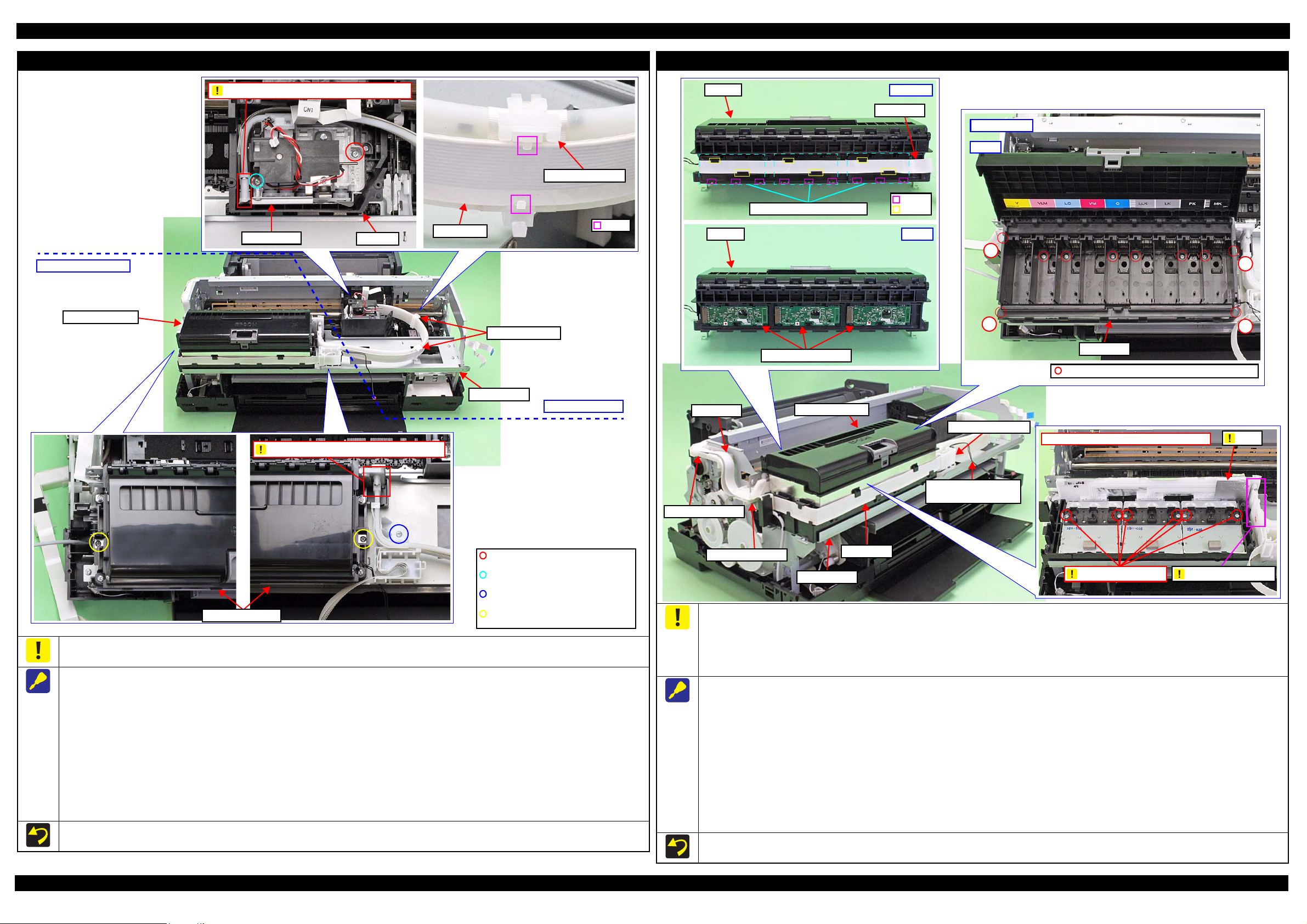
Do not use the electric screwdriver when installing the Printhead. Doing so applies extra force when tightening the screw and affects the platen gap.
To prevent ink leakage, make sure of the following when disassembling/reassembling the unit.
Do not remove the screws (x6) on the bottom of the Ink Box. Loosening the screws even just once will cause ink leakage, therefore, make sure to
replace the Ink Supply Unit with a new one.
Be careful not to damage the film of the ink path.
Be careful not to apply extra force on the Ink Tube connection.
When removing the CR Contact Modules (x3), follow the procedure below.
1. Disconnect the Head FFC and CSIC FFC from the connectors on the Main Board, and remove the Cable Holder Rear and Cable Holder Left
from the frame. (p 30)
2. Remove the Cable Holder Rear and Cable Holder Left from the CSIC FFC. (p 30)
3. Release the Head FFC from the ribs of the I/C Holder Unit. (p 29)
4. Release the I/C Holder Unit Cover Open Sensor Cable from the rib and hook of the Cable Holder Front. (p 29)
5. Remove the screws (x3) that secure the I/C Holder Unit. (p 22)
6. Remove the screws (x4) on the corners of the Ink Box and screws (x6) inside the Ink Box that secure the Ink Box.
7. Release the CSIC FFCs (x3) from the ribs (x6) of the Ink Box, and disconnect the CSIC FFCs (x3) from the connectors on the CR Contact
Modules (x3).
8. Release the hooks (x3 each) of the CR Contact Module Covers, and remove the CR Contact Module Covers and CR Contact Modules.
Tighten the screws in the order indicated in the figure above when securing the screws (x4) on the corner of the Ink Box.
Confidential
Page 23

Epson Stylus Photo R3000 Revision A
PF Frame
Main Frame
1
2
3
4
56
C.B.S-TITE SCREW,3X4,F/ZN-3C(8 1kgf·cm)
CR Motor
Red Cable
Black Cable
Rear right
Center
Step 1
Main Frame
Upper left
Step 1
Main Frame
Right
Bush, 8
Step 1
Rear Paper Guide
PF Roller
Step 2Step 3
Engagement point
with PF Roller
Positioning dowel
Main Frame
Upper Paper Guide Assy
The fourth roller of Upper Paper
Guide Assy from the 0-digit side
has shorter rubber parts.
Front
Torsion spring
Hook
Rear
Torsion spring
Hole
The rubber parts on roller are shorter.
0-digit side
130-digit side
Release Flag Assy
Gear Section
Rear left
1
2
3
4
5
6
Middle Frame
PF Frame
CR Motor
Rear Paper Guide
Tighten the screws in the order indicated in the figure above.
When installing the CR Motor, attach it with its red cable to the left
side of the printer.
Upper Paper Guide Assy
When removing the Rear Paper Guide, follow the procedure below.
1. Push the positioning dowels (x3) in the direction of the red arrow to release them.
2. Slide the Rear Paper Guide approx. 5 mm to the left to release the right side of the Rear Paper Guide from the Bush, 8.
3. Lift the rear side of the Rear Paper Guide and release it from the PF Roller, and then remove the Rear paper Guide.
Release Flag Assy
Middle Frame
Make sure to install the Upper Paper Guide Assy whose roller has shorter rubber parts on the fourth position from 0-digit side.
When attaching the torsion spring, insert the spring leg (straight side) into the hole of the Upper Paper Guide Assy, and engage the other leg to
the hook of the frame.
When installing the Release Flag Assy, install it with its gear
section upward.
Tighten the screws in the order indicated in the figure above.
Disassembly/Reassembly Detailed Disassembly/Reassembly Procedure for each Part/Unit 23
Confidential
Page 24

Epson Stylus Photo R3000 Revision A
Right
PG Torsion Spring Right
Step 8
PG Cam Right
Washer,
6.9X0.5X10.4
Step 3
Left
PG Torsion Spring Left
Step 3
C.B.S-TITE(P4) SCREW,3X10,F/ZN-3C
Step 4
Parallelism
Adjust Bushing
PG Cam Left
Step 8
Washer,
6.9X0.5X10.4
Left
CR Shaft Spacer
Step 5
Dent
Step 6
CR Shaft
Left CR Shaft
Mounting Plate
Step 7
Right
Dent
Step 6
CR Shaft
Step 9
Right CR Shaft Mounting Plate
Washer,
8.2X0.5X15
Leaf Spring,
8.2X0.25X15
CR Motor
Step 1
CR Shaft
CR Unit
C.B.SCREW,3X4,F/ZN-3C (4 ± 0.5 kgf·cm)
Timing Belt
1
2
3
Grounding Wire
ASF Assy
Grounding
wire
Main Frame
C.B.S-TITE(P4)SCREW,3X8,F/ZN-3C(8 1kgf·cm)
C.B.S-TITE SCREW,3X6,F/ZN-3C(8 1kgf·cm)
Cross-section
Ink System
Ink System
Clamp B
Clamp AHole
Pump Motor Cable
Ink System Tube
Support Plate
C.B.S-TITE SCREW,3X6,F/ZN-3C (8 ± 1 kgf·cm)
Right
CR Unit
ASF Assy
Tighten the screws in the order indicated in the figure above.
Attach the terminal of the grounding wire in the direction shown in the “Cross-section” figure.
Ink System
Be careful not to let the grease of the CR Shaft adhere to the Timing Belt of the CR Unit.
When removing the CR Unit, follow the procedure below.
1. Remove the screws (x2) that secure the CR Motor, and remove the CR Motor from the frame.
2. Mark the contact point on the Parallelism Adjust Bushing with the frame. (p 48)
3. Remove the PG Torsion Spring Left / Right.
4. Loosen the screw that secure the Parallelism Adjust Bushing, and turn the Parallelism Adjust Bushing in the direction of the arrow shown above.
Disassembly/Reassembly Detailed Disassembly/Reassembly Procedure for each Part/Unit 24
5. Remove the CR Shaft Spacer.
6. Lift the CR Shaft, and move both ends of it to the dent of the frame.
7. Remove the Left CR Shaft Mounting Plate.
8. Remove the Washer, 6.9X0.5X10.4 (x1 each) that secure the PG Cam Left/Right, and remove the PG Cam Left/Right from the CR Shaft.
9. Slide the CR Shaft to the left to disengage it from the frame, and from the right end of the CR Shaft, remove the Right CR Shaft Mounting Plate,
Washer, 8.2X0.5X15, and Leaf Spring, 8.2X0.25X15 in order.
10. Remove the left end of the CR Shaft from the frame, and remove it together with the CR Unit.
11. Remove the CR Shaft from the CR Unit.
When installing the CR Motor, install it by referring to “ CR Motor (p23)”.
Be careful not to mistake the PG Torsion Spring Right and PG Torsion Spring Left when installing them because they look alike.
Make sure to install the Parallelism Adjust Bushing correctly to the location with the marking drawn when removing it.
When removing the Ink System, follow the procedure below.
1. Release the Ink System Tube from the clamp A and pull out from the hole of the frame.
2. Release the Pump Motor Cable from the clamp B.
3. Remove the screws (x2) that secure the Support Plate, and remove the Support Plate.
4. Remove the screws (x2) that secure the Ink System, and remove it downward while avoiding the frame.
When securing the Ink System Tubes (x2) with the clamp A, make sure to arrange the shorter one to the bottom as shown.
Confidential
Page 25

Epson Stylus Photo R3000 Revision A
Step 5
Step 6
Right: Step 2-4
E-ring, 3
Spur Gear, 14.4
Torsion Spring, 187.9
Parallel Pin, 1.5
Front Tray Shaft
The location where
frame may interfere.
Front Right Tray Guide
Left: Step 4, 5
Front Left Tray Guide
The location where frame
may interfere.
The location where Front Paper
Guide Assy may interfere.
Front Right Tray Guide
Dowel
Hook
C.B.P-TITE SCREW,3X6,F/ZN-3C (4 ± 0.5 kgf·cm)
Front Tray
Front Tray Assy
The Front Tray is raised if
the gear is in this position.
Reassemble the Front Tray Assy with the Front Tray raised.
Stopper Tray Front Assy
Compression
Spring
This side is facing
to frame.
Attach Cover spring/
Compression spring
to shaft (longer side).
Cover Spring
Shaft
(shorter
side)
Link
Lever
Align shaft (shorter side)
of Link Lever to cam
groove of Stopper Tray.
Cam groove
E-ring, 3
Washer,
4.3X0.8X8
Stopper Tray
Torsion Spring, 187.9
C.B.P-TITE SCREW,3X8,F/ZN-3C(4 ± 0.5kgf·cm)
C.B.S-TITE SCREW,3X6,F/ZN-3C(8 ± 1kgf·cm)
EJ Link Left
Front Left Tray Guide
Washer,
26X0.5X4.7
Washer,
3.1X0.5X5.4
Extension Spring, 0.70
Tray Support Assy
EJ Link Right
Washer,
26X0.5X4.7
Front Right Tray Guide
Washer,
3.1X0.5X5.4
Extension Spring, 0.70
Tray Support Assy
Gear section of Front Tray
Washer,
3.1X0.5X5.4
Parallel Pin, 1.5Spur Gear, 14.4
Tray Support Assy
Back of Front Tray Assy
Front Tray
Front Tray Assy
Stopper Tray Unit
When removing the Stopper Tray Unit, follow the procedure below.
1. Remove the Torsion Spring, 187.9.
2. Remove the screws (x2) that secure the Stopper Tray Front Assy and remove the Stopper Tray Front Assy.
3. Remove the Lever Link with Cover Spring and Compression Spring.
4. Remove the E-ring, 3 and Washer, 4.3X0.8X8, and remove the Stopper Tray.
When attaching the Cover Spring to the Link Lever, attach it as shown above.
After reassembling the Stopper Tray Unit, confirm the Torsion Spring, 187.9 is correctly attached.
Tray Support Assy / Front Tray
When disassembling/reassembling the Front Tray Assy, there are some locations where the frame and the Front Paper Guide Assy may interfere.
Therefore, be careful not to deform the frame when working.
When removing the Front Tray Assy, follow the procedure below.
1. Remove the screw that secure the Mist Board Assy.
2. Remove the Torsion Spring, 187.9 on the right side of the Front Tray Assy.
3. Remove the E-ring, 3, and remove the Spur Gear, 14.4 and Parallel Pin, 1.5.
4. Remove the screws (x3) that secure the Front Tray Assy.
5. Release the hook and dowel of the Front Left Tray Guide from the frame and slide it to the front of the printer, and then lift the left side of the
Front Tray Assy.
Disassembly/Reassembly Detailed Disassembly/Reassembly Procedure for each Part/Unit 25
6. Release the hook and dowels (x2) of the Front Right Tray Guide from the frame and slide it to the front of the printer while avoiding the Front Paper
Guide Assy, and then remove the Front Tray Assy by pulling out the Front Tray Shaft and Front Right Tray Guide from the hole of the frame.
Reassemble the Front Tray Assy with the Front Tray raised. After reassembly, make sure the Front Tray Assy is secured with the hooks and
dowels, and then secure it with the screws.
After reassembling the Front Tray Assy, confirm the Torsion Spring, 187.9 is correctly attached.
Before reassembling the Tray Support Assy/Front Tray, confirm the Washer,3.1X0.5X5.4 (x2) and Washer,26X0.5X4.7 (x2) are correctly
attached.
When reassembling the Front Tray Assy, install each part as shown above, and secure them with their dedicated washer, parallel pin, and extension spring.
Before reassembling the Tray Support Assy/Front Tray, confirm the Washer,3.1X0.5X5.4 (x2) and Washer,26X0.5X4.7 (x2) are correctly attached.
Confidential
Page 26

Epson Stylus Photo R3000 Revision A
Star Wheel Assy
Dowel
Rib
Dowel position
EJ Slider Right
EJ Slider Left
EJ Link Left
Front Left Tray Guide
Left
Front Right Tray Guide
EJ Link RIght
Right
Head FFC
Printhead connecting side
Double-sided tape
attachment position
Dowel
Rib
Hook
EJ Slider Left
Step 1, 2
EJ Slider Right
C.B.S-TITE SCREW,3X8,
F/ZN-3C (8 ± 1 kgf·cm)
EJ Roller Front
EJ Roller Rear
EJ Grounding Spring
C.B.S-TITE SCREW,3X8,F/ZN-3C (5 ± 1 kgf·cm)
Right
Spring foot A
Spring foot B
Step 3, 4, 7
EJ Roller Rear
Washer
EJ Roller Front
Washer,
6.9X0.5X10.4
Left
Step 5
Bush, 8
Step 6
Front Paper Guide Assy
Step 8
Step 7
Front Paper Guide Assy
Bottom
Leg of Porous Pad Front Paper Guide
Leg of EJ Ink Guide Left/Right
OK
Rib of Porous Pad Front
Paper Guide is hidden.
NG
Rib of Porous Pad Front
Paper Guide is sticking out.
Front Paper Guide
1: EJ Ink Guide Right
3: EJ Ink Guide Left
4: Porous Pad Left Paper Guide
2: Porous Pad Front Paper Guide
Porous Pad Front Paper Guide
Rib
Leg
Star Wheel Assy
Head FFC
Front Paper Guide Assy
Attach the dowels on the left/right of the Star Wheel Assy from
the left one first into their attachment positions shown above.
Insert the ribs on the left/right of the Star Wheel Assy to the
grooves on the EJ Frame Slider Left/Right.
When installing the EJ Ink Guide Left/Right, Porous Pad Front Paper Guide and Porous Pad Left Paper Guide, install them in the order shown
above.
After installing the Porous Pad Front Paper Guide, make sure the legs (x10) of the Porous Pad Front Paper Guide and legs (x3) of the EJ Ink
Guide Left/Right are fully pulled out and they drop down straight from the hole of the Front Paper Guide Assy.
Make sure that all ribs (x47) of the Porous Pad Front Paper Guide are fitted into the grooves of the Front Paper Guide, and no pad lifts off from
the platen.
To prevent degradation of print quality due to interference of the
Head FFC (x2) with the CR Unit movement, the Head FFC (x2) are
folded with the jig and bundled together with double-sided tape.
When handling the Head FFC, take care not to make an extra fold
on it other than original ones. Furthermore, do not peel the FFC
apart or change the attachment locations.
Porous Pad Front Paper Guide
When removing the Front Paper Guide Assy, follow the procedure below.
1. Release the hooks (x3) and dowels (x2) of the EJ Slider Left, and remove the EJ Slider Left.
2. Remove the screw that secure the EJ Slider Right and release the dowels (x2) and rib, and then remove the EJ Slider Right.
3. Remove the EJ Grounding Spring on the right side of the Front Paper Guide Assy.
4. Remove the screw that secure the Front Paper Guide Assy.
5. Remove the Washer,6.9X0.5X10.4 from the EJ Roller Front.
6. Release the dowel of the Bush, 8 and rotate the Front Paper Guide Assy upward and align it with the cutout of the frame.
7. Slide the Front Paper Guide Assy to the left, and release the dowels (x2) on the right side of it from the frame.
8. Lift the front side of the Front Paper Guide Assy and detach the EJ Roller Front from the cutout of the frame, and then remove the Front Paper
Guide Assy while avoiding the parts around it.
When installing the EJ Grounding Spring, follow the procedure below.
1. Engage the Spring Foot A to the groove of the EJ Roller Front.
2. Engage the bent section of the EJ Grounding Spring on the inner side of the washer outside the EJ Roller Rear.
3. Engage the Spring Foot B to the hook of the frame.
Disassembly/Reassembly Detailed Disassembly/Reassembly Procedure for each Part/Unit 26
Confidential
Page 27

Epson Stylus Photo R3000 Revision A
Bush, 8
Left
Step 4
PF Roller
Compression Spring, 4
E-ring, 7
Left
Step 3
PF Grounding Spring
PF Roller
Step 1
Groove
Cutout
Bush, 8
Right
Step 2
PF Roller
Step 5
Mist Board AssyMist Board Cable Holder
Upper surface of
Mist Board
Rib and positioning hole
Insert shield plate of Mist Board Assy
under Mist Board Cable Holder.
Mist Board Cable Holder
Left
Board holder
Shield Plate Lower
Mist Board
C.B.S-TITE SCREW,3X6,F/ZN-3C (6 ± 1 kgf·cm)
Mist Board Assy
Right
Inside Mist Board Assy
PF Scale
PF Encoder Assy
PF Encoder
PF Scale
PF Roller
Mist Board Assy
When installing the Mist Board Assy, insert the shield plate of the
Mist Board Assy under the Mist Board Cable Holder, and align rib
of the Mist Board Assy with the positioning hole of the frame.
Mist Board
When attaching the Mist Board to the Shield Plate Lower, follow
the procedure below.
1. Attach the board holders (x3) to the Mist Board on the position
shown above.
2. Align the board holders (x3) on the corners of the Shield Plate
Lower, and attach the Mist Board to the Shield Plate Lower.
When removing the PF Roller, follow the procedure below.
1. Remove the PF Grounding Spring.
2. Release the dowel of the Bush, 8 on the right side of the PF Roller, and rotate it upward and align it with the cutout of the frame.
3. Remove the E-ring, 7 and slide the Compression Spring, 4 to the right.
4. Release the dowel of the Bush, 8 on the left side of the PF Roller, and rotate it upward and align it with the cutout of the frame.
5. Pull out the PF Roller to the left side from the hole of the frame and remove it from the frame.
When attaching the PF Grounding Spring, engage the longer bent leg to the groove of the PF Roller, and engage the other leg to the cutout of the
frame to secure the spring.
PF Scale / PF Encoder Assy
After installing the PF Encoder Assy, confirm the PF Encoder does not touch the PF Scale.
Disassembly/Reassembly Detailed Disassembly/Reassembly Procedure for each Part/Unit 27
Confidential
Page 28

Epson Stylus Photo R3000 Revision A
Screwdriver
150 mm or more
C.B.S-TITE SCREW,3X6,F/ZN-3C (8 ± 1 kgf·cm)
Shield Plate Assy Upper Main Board
1
Rear
2
3
Front
Lower Frame
Gap
A
Paper Guide (under ASF Assy)
Shield Plate Assy Upper Main Board
Shield Plate Assy Upper Main Board
When tightening the screw that secures the Shield Plate Assy
Upper Main Board, use a screwdriver with the shaft length of
150 mm or more and tighten the screw straight. Otherwise, you
have to screw it obliquely and can not tighten it correctly
because the grip of the driver hits the lower frame.
Tighten the screws in the order indicated in the figure above.
Board Assy
After installing the Board Assy, confirm the gap shown above is
uniform. If not, the Shield Plate Assy Upper Main Board pushes up
the Paper Guide (under ASF Assy). In such a case, loosen the
screw (A) and adjust the Shield Plate Assy Upper Main Board
position until the gap become even, then tighten the screw (A).
Disassembly/Reassembly Detailed Disassembly/Reassembly Procedure for each Part/Unit 28
Confidential
Page 29

Epson Stylus Photo R3000 Revision A
Panel Board
Panel FFCs
Upper Housing
Hole
Cover Open Sensor Cable
Upper Housing Support Assy
Hook
I/C Holder Unit Cover Open Sensor Cable:
make one turn around hook.
I/C Holder
Unit
Front
Cable Holder
Front
Rib
Hook
Head FFC
Upper
Cable Holder Front
I/C Holder Unit Head FFC
Rib
Cable Holder Front
I/C Holder Unit Cover
Open Sensor Cable
Decomp Pump Assy
Rib
Hook
Decomp Pump Motor Cable
Stopper Tray
Sensor Relay Cable
PictBridge Holder Assy CableDecomp Pump Motor Cable
Make two turns
around hook.
Groove
Rib
CR Encoder / PW Sensor FFC
Head FFC
Route Ink Selector Motor Cable
and Ink Selector Sensor Cable
through cutout of Ink Selector.
CR Relay Board
Ink Selector
CR Support Plate
Cable Holder
Acetate Tape B: 18 x 30 mm
Right
Rib
Acetate Tape A
Double-sided tape Reference line
PE Detector
Assy
PE Sensor Cable
Clamp
Release Holder AssyPanel FFC
Cross-section
2
1
3
4
Pump Motor Cable
Roll Paper Guide
Open Sensor Cable
ASF Motor Relay Cable
CR Motor Cable1
2
3
4
5
Cable Holder5
6
6
Shield Plate Assy Upper
Main Board
Cable Holder
Groove of Shield Plate
Assy Upper Main Board
1.4 Routing FFCs/cables
Upper Housing Support Assy
Route the Panel FFCs though the hole of the Upper Housing, and connect it to
the connector on the Panel Board.
Cover Open Sensor
When routing the Cover Open Sensor Cable, follow the procedure below.
1. Make one turn around the hook of the Upper Housing Support Assy
without slack between the Cover Open Sensor and the hook.
2. Connect the cable to the connector on the Panel Board.
3. Roll up the slack cables between the connector on the Panel Board and the
hook as shown above.
Head FFC
Route the Head FFC through the I/C Holder Unit and Cable Holder Front as shown above.
When routing the I/C Holder Unit Cover Open Sensor Cable, make one turn around the hook of the I/C Holder Unit and route through the ribs (x4) of the
Cable Holder Front, and then make one turn around the hook of the Cable Holder Front.
PictBridge Holder Assy / Decomp Pump Assy
When routing the Decomp Pump Motor Cable through the Decomp Pump
Assy, route the cable through the following ribs and hooks.
• Ribs (x3) and hook on the upper side of the Decomp Pump Assy
• Hooks (x4) and ribs (x2) on the side of the Decomp Pump Assy
Route the following cables through the ribs and grooves of the Lower Housing.
• Decomp Pump Motor Cable
• PictBridge Holder Assy Cable
• Stopper Tray Sensor Relay Cable
Disassembly/Reassembly Routing FFCs/cables 29
Route the following cables/FFCs as shown above and connect them to the
connectors on the CR Relay Board.
Ink Selector Motor Cable (CN2)
Ink Selector Sensor Cable (CN5)
Head FFC (CN1)
CR Encoder / PW Sensor FFC (CN6)
CR Support Plate / Ink Selector
Upper side of the Board Assy
Route the Panel FFC through the ribs (x2) along with the reference line as shown above, and secure it with double-sided tape and two pieces of acetate tape A.
Route the PE Sensor Cable through the ribs (x6) of the Release Holder Assy, and secure it with the clamp.
Attach acetate tape B (18 x 30 mm) on the position shown above.
Route the cables through the groove on the Shield Plate Assy Upper Main Board arranging them in the order shown in “cross-section” above, and secure
them with the Cable Holders (x2).
Confidential
Page 30

Epson Stylus Photo R3000 Revision A
CN # Name CN # Name CN # Name
CN1
Stopper Tray
Open Sensor Relay Cable
CN8 Head FFC CN20
Roll Paper Guide
Open Sensor Cable
CN9 Head FFC CN22 Decomp Motor Cable
CN2 CSIC FFC CN10 Head FFC CN115 CR Motor Cable
CN3 PictBridge Holder Cable CN11 Head FFC CN116 PF Motor Cable
CN4 Panel FFC CN12 Head FFC CN117 Pump Motor Cable
CN5 Panel FFC CN13 Mist Board FFC CN118 APG Motor Cable
CN6 ASF Relay Board FFC CN15 CSIC FFC CN119 ASF Motor Cable
CN7 Wireless LAN Module Cable CN19 CSIC FFC
Route Panel FFC
over ASF Assy.
Reference line
Double-sided tape
PF Encoder FFC
Panel FFC
Around ASF Relay Board
Route PE Sensor Cable
under rib of ASF Assy.
ASF Relay Board
APG HP Sensor Cable
APG Position
Sensor Cable
Double-sided tape
PF Encoder FFC
Secure PF Motor
Cable with clamp.
ASF Motor
Cable
Pump Motor
Cable
CR Motor
Cable
Roll Paper Guide
Open Sensor Cable
APG Motor Cable
PF Motor Cable
Head FFC/CSIC FFC
PictBridge Holder Cable
Stopper Tray Open Sensor Relay Cable:
Pull out through hole of Lower Housing and make
one turn around hook, then connect to Main Board.
Decomp Motor Cable
CN2
CN15
CN11
CN9
CN8
CN10
CN12
CN4CN13
CN5
CN19
CN1
CN7
CN20
CN6
CN118
CN115
CN119
CN3
CN117
CN116
CN22
When routing the following FFCs,
route them through groove of ASF
Assy under Roll Paper Guide Assy.
Head FFC
CSIC FFC
Panel FFC
Hook
Refer below for the connector layout on the Main Board for the cables/FFCs. The connector numbers are marked on each FFC, therefore, make sure of it when
connecting them.
ASF Relay Board FFC
CN #
Name
CN #
Name
CN #
Name
CN1
ASF Relay
Board FFC
CN2
PE Sensor
Cable
CN6
PF Encoder
FFC
ASF Assy
Hole
Route Head FFC through groove on left side of I/C
Holder Unit, and route it to Cable Holder Left.
Route CSIC FFC through groove of Cable Holder
Left, and route it to Cable Holder Rear.
Double-sided tape
Rib
Head FFC
CSIC FFC
Cable Holder Rear
Double-sided tape
Cable Holder Left
Clamp A
ASF Motor Cable
ASF Motor Cable
Clamp B
Roll Paper Guide
Open Sensor
CR Motor Cable
Grounding wire
Pump Motor Cable
Screw with
ASF Motor
ASF Motor
Relay Cable
Rear left of printer (1)
Rear left of printer (2)
Fold the Head FFC / CSIC FFC along the hold line, and route them through the ribs (x6) of the Cable Holder Rear, Cable Holder Left, and the ribs (x3) on
the left side of the I/C Holder Unit.
Route the CSIC FFC over the Head FFC and secure the CSIC FFC with double-sided tape at the points shown in the figure above.
Rear right of printer
Disassembly/Reassembly Routing FFCs/cables 30
Screw the grounding wire together with the ASF Motor.
Connect the ASF Motor Cable to the ASF Motor Relay Cable, and then secure it with the clamp A.
Be careful not to let the ASF Motor Relay Cable interfere with the Roll Paper Guide Open Sensor when routing it.
Secure the Pump Motor Cable with the clamp B.
Confidential
Page 31

Epson Stylus Photo R3000 Revision A
Mist Board Cable Holder
Mist Board Cable Holder
Electrode cable
Cutout
Groove A
Groove B
Mist Board Assy
Double-sided tape
Reference line
Mist Board FFC connector
Double-sided tape
Reference line
Rib
Main Frame
Section A
Hook
Step 4
Mist Board FFC
Right side of Main Frame
Cable Holder Right
Mist Board FFC
Hole of Main Frame
Groove
Panel FFC
Step 1 to 3
Main Frame
Mist Board Assy / Right side of the Main Frame
When routing the FFCs/cables on the Mist Board Assy and the FFC on right side of the Main Frame, follow the procedure below.
1. Before installing the Cable Holder Right to the Main Frame, route the Mist Board FFC through the groove and ribs (x3) of the Cable Holder Right.
2. Route the Mist Board FFC and Panel FFC along the reference line of the Main Frame in order, and secure them to the Main Frame with double-sided
tape.
3. Route the Mist Board FFC through the hole of the Main Frame.
4. Engage the section A of the Cable Holder Right to the Main Frame as shown above, and then secure the Cable Holder Right to the Main Frame with the
hooks (x2).
5. Route the Mist Board FFC along the reference line of the Mist Board Assy, and secure the Mist Board FFC to the Mist Board Assy with double-sided
tape.
6. Connect the Mist Board FFC to the Mist Board FFC connector.
Pull out the electrode cable from the cutout of the Main Frame and route the cable through the groove A and B as shown above, and then connect it to the
Mist Board.
Disassembly/Reassembly Routing FFCs/cables 31
Confidential
Page 32

CHAPTER 2
ADJUSTMENT
Confidential
Page 33

Epson Stylus Photo R3000 Revision A
2.1 Required Adjustments
The table from the following page lists the required adjustments depending upon the parts being repaired or
replaced. Find the part(s) you removed or replaced, and check which adjustment(s) must be carried out.
If the EEPROM data cannot be read out from the old Main Board using the Adjustment
Program when replacing the Main Board is required, the Waste Ink Pad and Lower
Paper Guide Ink Pad Tray must be replaced with the Main Board at the same time.
After all required adjustments are completed, use the “Final check pattern print”
function to print all adjustment patterns for final check. If you find a problem with the
printout patterns, carry out the adjustment again.
When replacing the Main Board and the Printer Mechanism at the same time, the
adjustment should be made after performing the initial setting.
The table items and marks used in the “Required Adjustment List” provided on the
following pages have the following meanings.
• “O” indicates that the adjustment must be carried out.
• “---” indicates that the adjustment is not required.
• The “Mechanism Adjustment” should be performed just after reinstalling or
reassembling the part or unit. (See “ Table2-1 Required Adjustment List (Mechanism
Adjustment) (p34)”)
• The “Adjustments using the Adjustment Program” need to be performed after
reassembling the printer completely. (See “ Table2-2 Required Adjustment List
(Adjustment Program) (p35)”)
If you have removed or replaced multiple parts, make sure to check the required
adjustments for the all parts. And when multiple adjustments must be carried out, be
sure to carry out them in the order given in the “Priority” row.
Adjustment Required Adjustments 33
Confidential
Page 34

Epson Stylus Photo R3000 Revision A
Table 2-1. Required Adjustment List (Mechanism Adjustment)
Adjustment Type Mechanism adjustment
Priority 1 2 3 4 5
Adjustment Item
Purpose
Printer
Mechanism
PF Motor
Printhead
CR Unit
LD Roller
Part Name
Guide
Front Paper
Guide Assy
PF Roller
Mist Board
*
2
Assy
How to judge
Adjustment program
Tool
Replace
Remove
Replace
Remove
Replace
Remove
Replace
Remove
Replace
Remove
Replace
Remove
Replace
Remove
Replace
PF Belt Tension
Adjustment
To reduce the load on
the PF motor and to
ensure paper feed
accuracy.
PF Roller Shaft
Center Support
Position Adjustment
To compensate the
deflection amount on
the PF Roller Shaft
and to maintain the
appropriate paper feed
amount.
OOOOO
O --- --- --- ---
O --- --- --- ---
--- --- --- O ---
--- --- --- O ---
--- --- --- O ---
--- --- --- O ---
--- --- O
--- --- O --- ---
--- --- --- O O
--- --- --- O O
O O --- --- ---
O O --- --- ---
--- --- --- --- ---
--- --- --- --- O
See “ 2.2.1 PF Timing
Belt Tension
Adjustment (p38)” for
the details.
See “ 2.2.2 PF Roller
Shaft Center Support
Position Adjustment
(TBD) (p39) ” for the
details.
--- --- --- --- ---
(See p 38) (See p 39) (See p 44) (See p 47) (See p 51)
ASF Guide Roller
LDs position
adjustment
To correct the position
of the LD Roller in
order to maintain the
paper feed accuracy.
*1
See “ 2.2.3 ASF Guide
Roller LDs position
adjustment (p44)” for
the details.
PG Adjustment
To secure the
specified clearance
between the print
surface of the
Printhead and paper,
and adjust the
parallelism of the 0digit and 130-digit
sides in order to
maintain the print
quality.
--- ---
See “ 2.2.4 PG
Adjustment (p47) ” for
the details.
Mist Recovery
check
To confirm the
voltage applied to the
plate under the Front
Paper Guide Assy is
proper for ink mist
recovery inside the
printer.
See “ 2.2.5 Mist
Recovery check
(p51)” for the details.
Note 1: The adjustment is not necessary for the parts other than mentioned.
2: Make sure to perform the adjustment using the Adjustment Program after mechanism adjustment is complete.
(See “ Table2-2 Required Adjustment List (Adjustment Program) (p35)” for the details.)
Note "*1" : The adjustment is not necessary if you mark the installing positions of the LD Roller Guides before removing them, and align the markings
when installing the LD Roller Guides.
"*2": Only removing/replacing the Mist Board is included.
Adjustment Required Adjustments 34
Confidential
Page 35

Epson Stylus Photo R3000 Revision A
TBD
TBD
Table 2-2. Required Adjustment List (Adjustment Program)
Adjustment Type Adjustment using the Adjustment Program
Priority (TBD) 1 2 3 4 5 6 7 8 9 10 11 12 13 14 15 16 17 18 19 20
Adjustment Item
Waste Ink Pad
Lower Paper
Guide Ink Pad
Tray
Printer
Mechanism
APG Assy
APG Motor
Part Name
Board Assy*
(Main Board/
Power Supply
Board)
Power Supply
Board
PF Motor
Purpose
Remove
Replace
Remove
Replace
Replace
Remove
Replace
Remove
Replace
Remove
Replace
(Read OK)
Replace
(Read NG)
Remove
Replace
Remove
Replace
CR motor
heat
protection
control
To measure
and correct the
electrical
variation of
the motor and
the power
supply board.
EEPROM
Data Copy
To copy
adjustment
values or the
like stored on
the old Main
Board to the
new board when
the Main Board
needs to be
Initialize
Setting
To write salesdestinationspecific
settings and
the serial
number into
the Main
Board after
replacing it.
Head ID
Input
To correct
characteristic
variation of
the replaced
Printhead by
entering its
Printhead ID
(Head ID).
MAC
address
Input
To input the
MAC address
if the data in
EEPROM
cannot be read
out.
Waste Ink
Pad Counter
To reset the
waste ink
counter after
replacing the
Waste Ink Pad.
Ink Selector
Counter
To reset the
selector
counter after
replacing the
Ink Supply
Unit.
Ink charge
To fill ink
inside the new
Printhead to
make it ready
for print after
replacing the
Printhead.
Release of
Driven roller
check
To check the
release
operation of
driven rollers.
Front Tray
print counter
To initialize
the Front Tray
print counter
according to
the replaced
parts.
PF
deterioration
offset
To initialize
the PF
deterioration
offset counter
according to
the replaced
parts.
Diaphragm
Pump check
PK/MK
To check if the
diaphragm
pump operates
normally and
nozzle is not
clogging.
Head angular
adjustment
CR/PF
To correct the
head angular
(in CR/PF
direction)
when
installing the
Printhead.
First Dot
adjustment
PW
adjustment
To correct the print start
position in the carriage moving
direction through software
control.
Bi-D
adjustment
To correct
print start
timing in
bidirectional
printing
through
software
control.
PF / EJ
adjustment
To correct
variations in
paper feed
accuracy to
achieve higher
print quality.
replaced.
--- --- --- --- --- --- --- --- --- --- --- --- --- --- --- --- --- --- --- O
--- --- --- --- O --- --- --- --- --- --- --- --- --- --- --- --- --- --- O
--- --- --- --- --- --- --- --- --- --- --- --- --- --- --- --- --- --- --- O
--- --- --- --- O --- --- --- --- --- --- --- --- --- --- --- --- --- --- O
--- --- --- --- O --- --- O
O
Reset to 0OReset to 0
---OOOOOOO---O
--- --- --- --- --- --- --- --- --- --- --- --- --- --- --- --- --- --- --- O
--- --- --- --- --- --- --- O --- --- --- --- --- --- --- --- --- --- --- O
--- --- --- --- --- --- --- --- --- --- --- --- --- --- --- --- --- --- --- O
--- --- --- --- --- --- --- O --- --- --- --- --- --- --- --- --- --- --- O
--- --- --- --- --- --- --- --- --- --- --- --- --- --- --- --- --- --- --- O
O --- --- --- --- --- --- --- --- --- --- --- --- --- --- --- --- --- --- O
--- O O O --- O --- ---
O
Input max.
value
O
Input max.
value
---OOOOOOOOO
--- --- --- --- --- --- --- --- --- --- --- --- --- --- --- --- --- --- --- O
--- --- --- --- --- --- --- --- --- --- --- --- --- --- --- --- O O O O
--- --- --- --- --- --- --- --- --- --- --- --- --- --- --- --- --- --- --- O
--- --- --- --- --- --- --- --- --- --- --- --- --- --- --- --- --- O --- O
PF motor
heat
protection
control
To measure
and correct the
electrical
variation of
the motor and
the power
supply board.
Colorimetric
calibration
To register the
Color ID to
ensure
consistent
color quality.
Final check
pattern print
To check if all
the
adjustments
have been
properly made.
OK
NG
NG
OK NGNG
Examine the
printout
patterns and
enter the value
for the pattern
with no
overlap and
gap between
the two
rectangles.
--- ---
See “ 2.2.8
Colorimetric
Calibration
(p55)” for the
details.
---
Printout pattern
How to judge
-2
--- --- --- --- --- --- --- --- --- --- --- --- --- ---
--- --- ---
See “ 2.2.6
MAC address
setting (p52)”
for the details.
--- --- --- --- --- --- ---
See “ 2.2.7
Head Angular
Adjustment
CR/PF (TBD)
(p53)” for the
details.
-1
0
1
2
Examine the
lines on the
left side of
paper, and
enter the
number beside
the line that
overlaps with
the horizontal
line.
-2 -1 0 1 2
-2
-2
-1
-1
0
0
1
1
2
2
-2 -1 0 1 2
Examine the
misaligned lines
printed on top,
bottom, left, and
right of the
paper, and enter
the number
beside the line
that is exactly 5
mm away from
OK
NG
NG
Examine the
printout
patterns, and
enter the value
for the pattern
with no gap
and overlap.
the paper edge
for each side.
Adjustment program
Tool
OOOOOOOOOOOOOOOOOOOO
--- --- --- --- --- --- --- --- --- --- --- --- Ruler Ruler --- --- --- --- --- ---
Note"*":Only removing/replacing the Main Board is included.
Adjustment Required Adjustments 35
Confidential
Page 36

Epson Stylus Photo R3000 Revision A
TBD
TBD
Table 2-2. Required Adjustment List (Adjustment Program)
Adjustment Type Adjustment using the Adjustment Program
Priority (TBD) 1 2 3 4 5 6 7 8 9 10 11 12 13 14 15 16 17 18 19 20
Adjustment Item
Ink Supply Unit
Printhead
CR Unit
PF Frame
Rear Paper
Guide
ASF Assy
Part Name
Release Holder
Assy
Release Flag
Assy
Upper Paper
Guide Assy
CR Motor
Purpose
Remove
Replace
Remove
Replace
Remove
Replace
Remove
Replace
Remove
Replace
Remove
Replace
Remove
Replace
Remove
Replace
Remove
Replace
Remove
Replace
CR motor
heat
protection
control
To measure
and correct the
electrical
variation of
the motor and
the power
supply board.
EEPROM
Data Copy
To copy
adjustment
values or the
like stored on
the old Main
Board to the
new board when
the Main Board
needs to be
Initialize
Setting
To write salesdestinationspecific
settings and
the serial
number into
the Main
Board after
replacing it.
Head ID
Input
To correct
characteristic
variation of
the replaced
Printhead by
entering its
Printhead ID
(Head ID).
MAC
address
Input
To input the
MAC address
if the data in
EEPROM
cannot be read
out.
Waste Ink
Pad Counter
To reset the
waste ink
counter after
replacing the
Waste Ink Pad.
Ink Selector
Counter
To reset the
selector
counter after
replacing the
Ink Supply
Unit.
Ink charge
To fill ink
inside the new
Printhead to
make it ready
for print after
replacing the
Printhead.
Release of
Driven roller
check
To check the
release
operation of
driven rollers.
Front Tray
print counter
To initialize
the Front Tray
print counter
according to
the replaced
parts.
PF
deterioration
offset
To initialize
the PF
deterioration
offset counter
according to
the replaced
parts.
Diaphragm
Pump check
PK/MK
To check if the
diaphragm
pump operates
normally and
nozzle is not
clogging.
Head angular
adjustment
CR/PF
To correct the
head angular
(in CR/PF
direction)
when
installing the
Printhead.
First Dot
adjustment
PW
adjustment
To correct the print start
position in the carriage moving
direction through software
control.
Bi-D
adjustment
To correct
print start
timing in
bidirectional
printing
through
software
control.
PF / EJ
adjustment
To correct
variations in
paper feed
accuracy to
achieve higher
print quality.
replaced.
--- --- --- --- --- --- --- --- --- --- --- --- --- --- --- --- --- --- --- O
--- --- --- --- --- O O --- --- --- O --- --- --- --- --- --- --- --- O
--- --- --- --- --- --- --- --- --- --- --- O O O O O --- --- O O
--- --- O --- --- --- O --- --- --- --- O O O O O --- --- O O
--- --- --- --- --- --- --- --- --- --- --- O O O O O --- --- --- O
--- --- --- --- --- --- --- --- --- --- --- O O O O O --- --- --- O
--- --- --- --- --- --- --- --- --- --- --- --- --- --- --- --- --- --- --- O
--- --- --- --- --- --- --- --- --- --- --- --- --- --- --- O --- --- --- O
--- --- --- --- --- --- --- --- --- --- --- --- --- --- --- --- --- --- --- O
--- --- --- --- --- --- --- --- --- --- --- --- --- --- --- O --- --- --- O
--- --- --- --- --- --- --- --- --- --- --- --- O --- --- --- --- --- --- O
--- --- --- --- --- --- --- --- --- --- --- --- O --- --- --- --- --- --- O
--- --- --- --- --- --- --- O --- --- --- --- --- --- --- --- --- --- --- O
--- --- --- --- --- --- --- O --- --- --- --- --- --- --- --- --- --- --- O
--- --- --- --- --- --- --- O --- --- --- --- --- --- --- --- --- --- --- O
--- --- --- --- --- --- --- O --- --- --- --- --- --- --- --- --- --- --- O
--- --- --- --- --- --- --- O --- --- --- --- --- --- --- --- --- --- --- O
--- --- --- --- --- --- --- O --- --- --- --- --- --- --- --- --- --- --- O
--- --- --- --- --- --- --- --- --- --- --- --- --- --- --- --- --- --- --- O
--- --- --- --- --- --- --- --- --- --- --- --- --- --- --- --- O --- --- O
PF motor
heat
protection
control
To measure
and correct the
electrical
variation of
the motor and
the power
supply board.
Colorimetric
calibration
To register the
Color ID to
ensure
consistent
color quality.
Final check
pattern print
To check if all
the
adjustments
have been
properly made.
OK
NG
NG
OK NGNG
Examine the
printout
patterns and
enter the value
for the pattern
with no
overlap and
gap between
the two
rectangles.
--- ---
See “ 2.2.8
Colorimetric
Calibration
(p55)” for the
details.
---
Printout pattern
How to judge
-2
--- --- --- --- --- --- --- --- --- --- --- --- --- ---
--- --- ---
See “ 2.2.6
MAC address
setting (p52)”
for the details.
--- --- --- --- --- --- ---
See “ 2.2.7
Head Angular
Adjustment
CR/PF (TBD)
(p53)” for the
details.
-1
0
1
2
Examine the
lines on the
left side of
paper, and
enter the
number beside
the line that
overlaps with
the horizontal
line.
-2 -1 0 1 2
-2
-2
-1
-1
0
0
1
1
2
2
-2 -1 0 1 2
Examine the
misaligned lines
printed on top,
bottom, left, and
right of the
paper, and enter
the number
beside the line
that is exactly 5
mm away from
OK
NG
NG
Examine the
printout
patterns, and
enter the value
for the pattern
with no gap
and overlap.
the paper edge
for each side.
Adjustment program
Tool
Note"*":Only removing/replacing the Main Board is included.
OOOOOOOOOOOOOOOOOOOO
--- --- --- --- --- --- --- --- --- --- --- --- Ruler Ruler --- --- --- --- --- ---
Adjustment Required Adjustments 36
Confidential
Page 37

Epson Stylus Photo R3000 Revision A
TBD
TBD
Table 2-2. Required Adjustment List (Adjustment Program)
Adjustment Type Adjustment using the Adjustment Program
Priority (TBD) 1 2 3 4 5 6 7 8 9 10 11 12 13 14 15 16 17 18 19 20
Adjustment Item
Stopper Tray
Unit
Tray Detector
Front Tray
Assy
Tray Support
Assy
Front Tray
Part Name
Star Wheel
Assy
Front Paper
Guide Assy
PF Roller
Purpose
Remove
Replace
Remove
Replace
Remove
Replace
Remove
Replace
Remove
Replace
Remove
Replace
Remove
Replace
Remove
Replace
CR motor
heat
protection
control
To measure
and correct the
electrical
variation of
the motor and
the power
supply board.
EEPROM
Data Copy
To copy
adjustment
values or the
like stored on
the old Main
Board to the
new board when
the Main Board
needs to be
Initialize
Setting
To write salesdestinationspecific
settings and
the serial
number into
the Main
Board after
replacing it.
Head ID
Input
To correct
characteristic
variation of
the replaced
Printhead by
entering its
Printhead ID
(Head ID).
MAC
address
Input
To input the
MAC address
if the data in
EEPROM
cannot be read
out.
Waste Ink
Pad Counter
To reset the
waste ink
counter after
replacing the
Waste Ink Pad.
Ink Selector
Counter
To reset the
selector
counter after
replacing the
Ink Supply
Unit.
Ink charge
To fill ink
inside the new
Printhead to
make it ready
for print after
replacing the
Printhead.
Release of
Driven roller
check
To check the
release
operation of
driven rollers.
Front Tray
print counter
To initialize
the Front Tray
print counter
according to
the replaced
parts.
PF
deterioration
offset
To initialize
the PF
deterioration
offset counter
according to
the replaced
parts.
Diaphragm
Pump check
PK/MK
To check if the
diaphragm
pump operates
normally and
nozzle is not
clogging.
Head angular
adjustment
CR/PF
To correct the
head angular
(in CR/PF
direction)
when
installing the
Printhead.
First Dot
adjustment
PW
adjustment
To correct the print start
position in the carriage moving
direction through software
control.
Bi-D
adjustment
To correct
print start
timing in
bidirectional
printing
through
software
control.
PF / EJ
adjustment
To correct
variations in
paper feed
accuracy to
achieve higher
print quality.
replaced.
--- --- --- --- --- --- --- O --- --- --- --- --- --- --- --- --- --- --- O
--- --- --- --- --- --- --- O --- --- --- --- --- --- --- --- --- --- --- O
--- --- --- --- --- --- --- O --- --- --- --- --- --- --- --- --- --- --- O
--- --- --- --- --- --- --- O --- --- --- --- --- --- --- --- --- --- --- O
--- --- --- --- --- --- --- O --- --- --- --- --- --- --- --- --- --- --- O
--- --- --- --- --- --- --- O --- --- --- --- --- --- --- --- --- --- --- O
--- --- --- --- --- --- --- O --- --- --- --- --- --- --- --- --- --- --- O
--- --- --- --- --- --- --- O --- --- --- --- --- --- --- --- --- --- --- O
--- --- --- --- --- --- --- O --- --- --- --- --- --- --- --- --- --- --- O
--- --- --- --- --- --- --- O --- --- --- --- --- --- --- --- --- --- --- O
--- --- --- --- --- --- --- O --- --- --- --- --- O --- O --- --- --- O
--- --- --- --- --- --- --- O --- --- --- --- --- O --- O --- --- --- O
--- --- --- --- --- --- --- --- --- --- --- --- O O O O --- --- --- O
--- --- --- --- --- --- --- --- --- --- --- --- O O O O --- --- --- O
--- --- --- --- --- --- --- --- --- --- --- --- --- --- --- O --- --- --- O
--- --- --- --- --- --- --- ---
O
Reset to 0OReset to 0
--- --- --- --- --- O --- --- --- O
PF motor
heat
protection
control
To measure
and correct the
electrical
variation of
the motor and
the power
supply board.
Colorimetric
calibration
To register the
Color ID to
ensure
consistent
color quality.
Final check
pattern print
To check if all
the
adjustments
have been
properly made.
Printout pattern
How to judge
Adjustment program
Tool
--- --- --- --- --- --- --- --- --- --- --- --- --- ---
--- --- ---
OOOOOOOOOOOOOOOOOOOO
--- --- --- --- --- --- --- --- --- --- --- --- Ruler Ruler --- --- --- --- --- ---
Note"*":Only removing/replacing the Main Board is included.
See “ 2.2.6
MAC address
setting (p52)”
for the details.
--- --- --- --- --- --- ---
See “ 2.2.7
Head Angular
Adjustment
CR/PF (TBD)
(p53)” for the
details.
-2
-1
0
1
2
Examine the
lines on the
left side of
paper, and
enter the
number beside
the line that
overlaps with
the horizontal
line.
-2 -1 0 1 2
-2
-2
-1
-1
0
0
1
1
2
2
-2 -1 0 1 2
Examine the
misaligned lines
printed on top,
bottom, left, and
right of the
paper, and enter
the number
beside the line
that is exactly 5
mm away from
the paper edge
for each side.
OK
NG
NG
Examine the
printout
patterns, and
enter the value
for the pattern
with no gap
and overlap.
OK
NG
NG
OK NGNG
Examine the
printout
patterns and
enter the value
for the pattern
with no
overlap and
gap between
the two
rectangles.
--- ---
See “ 2.2.8
Colorimetric
Calibration
(p55)” for the
details.
---
Adjustment Required Adjustments 37
Confidential
Page 38

Epson Stylus Photo R3000 Revision A
Left side
Microphone of sonic tension gauge
Adjuster part of the PF Motor attachment location
PF Timing Belt
2.2 Details of Adjustments (TBD)
This section provides adjustment procedures for which explanation in details is necessary. See “2.1 Required
Adjustments (p33)” for the adjustments not explained here.
2.2.1 PF Timing Belt Tension Adjustment
This section describes PF Timing Belt tension adjustment.
Tools
Sonic tension gauge
Plastic tweezers
Adjustment procedure
When performing the PF Timing Belt tension measurement, make sure of the following.
Bring the microphone of the sonic tension gauge within 5 mm from the Timing Belt but do
not let it touch the belt.
Flip the Timing Belt as weak as the sonic tension gauge can measure it.
Be careful not to damage the Timing belt when flipping it with the plastic tweezers.
1. Set the following parameters to the sonic tension gauge.
Weight: 001.2 g/m
Width: 005.0 mm
Span: 0048 mm
2. Bring the microphone of the sonic tension gauge close to the upper center of the PF Timing Belt.
3. Press the “MEASURE” button on the sonic tension gauge and flip the timing belt with plastic tweezers.
Figure 2-1. Microphone Position
The standard tension range of the PF Timing Belt Tension Adjustment is as follows:
Standard value: 10.5 2N (8.5 - 12.5N)
4. The adjustment is not necessary if the measured value falls within the standard value.
If not, loosen the screws that secure the PF Motor, and change the position of the PF Motor adjuster part of
the PF Motor attachment location little by little to adjust the belt tension. Repeat Step 3 until the measured
value falls within the standard value.
Adjustment Details of Adjustments (TBD) 38
Confidential
Page 39

Epson Stylus Photo R3000 Revision A
TBD
2.2.2 PF Roller Shaft Center Support Position Adjustment (TBD)
This section describes PF Roller Shaft Center Support Position Adjustment.
This adjustment must be performed to compensate the deflection amount on the PF Roller Shaft and to maintain
an appropriate paper feed amount.
Tools
A substitute level block can be used if its surface accuracy is within 50 .
PF Roller Shaft Center Support Position Adjustment Jig (TBD)
Level Block
Figure 2-2. PF Roller Shaft Center Support Position Adjustment Jig and Level Block (TBD)
Adjustment procedure
1. Install the PF Roller, and reassemble the unit up to the APG Assy.
(See “1-4 Disassembly Flowchart of Printer Mechanism Part (3) (p18)” for details.)
Adjustment Details of Adjustments (TBD) 39
Confidential
Page 40

Epson Stylus Photo R3000 Revision A
0 position
TBD
TBD
Center Support
Bushing Cam
2. Install the printer on a level workbench.
Place the printer on a level, warp-free table. This adjustment cannot be performed correctly if
it is performed on a warped table.
3. Set the PF Roller Shaft Position Adjustment Jig in place on the Level block, and perform zero adjustment.
Long hand position: Turn the dial to adjust the “0” position on the scale to the long hand position with the jig set in
place on the Level block.
Short hand position: Check it.
Figure 2-3. Setting the PF Roller Shaft Position Adjustment Jig (1)
4. Tilt the Printer Mechanism at about 45 degrees, and loosen the screw that secures the Center Support
Bushing Cam.
Figure 2-4. Center Support Bushing Cam and the Screw
Adjustment Details of Adjustments (TBD) 40
Confidential
Page 41

Epson Stylus Photo R3000 Revision A
TBD
TBD
TBD
TBD
Check for any dirt on the PF Roller Shaft when performing the following procedure.
5. Set the jig in place on the PF Roller Shaft as shown in the figure below.
Left side : Inside of PF Roller’s left end (E-ring)
Right side : Clearance between PF Roller right end (Right Bushing 8) and left end of Upper Paper Guide
Center : Clearance between the 2nd Upper Paper Guide and 3rd one from the left
Figure 2-5. Setting the PF Roller Shaft Position Adjustment Jig
Adjustment Details of Adjustments (TBD) 41
Confidential
Page 42

Epson Stylus Photo R3000 Revision A
down
up
Center Support
Bushing Cam
The standard range of the PF Roller Shaft Center Support Position Adjustment is as follows:
Standard value: -20 m - 30 m
Adjustment resolution: 50 m (TBD)
6. Turn the Center Support Bushing Cam so that the long hand position is +5 m from the “0” adjustment
position. (TBD)
+5 m must be set to compensate for the thickness of the coating on the PF Roller Shaft.
(TBD)
Make sure that the position of the short hand is the same as at “0” adjustment.
Figure 2-6. Positional Relationship between Center Support Bushing Cam and the Dial Gage
7. Tighten the screw that secures the Center Support Bushing Cam.
Check the adjustment value again as it deviates slightly when the screw is tightened.
Adjustment Details of Adjustments (TBD) 42
Confidential
Page 43

Epson Stylus Photo R3000 Revision A
Unevenness
Outside the specified value range Inside the specified value range
TBD
TBD
The following shows print samples when adjustment of the PF Roller Shaft Center Support Positions are inside
and outside the specified value range.
Figure 2-7. Print Sample
Adjustment Details of Adjustments (TBD) 43
Confidential
Page 44

Epson Stylus Photo R3000 Revision A
Front
Dowel
Rib
LD Roller Shaft
LD Roller Guide
C.B.SCREW,3X6,F/ZN-3C (8 ± 1 kgf·cm)
LD Roller Guide
Combination Gear 29.11
Hopper Pad
LD Roller
Upper side of ASF
Right
2.2.3 ASF Guide Roller LDs position adjustment
This section describes ASF Guide Roller LDs position adjustment.
When installing the LD Roller Guides, the position of the LD Roller Guides must be adjusted so that the positions
of the LD Roller Shaft and Retard Roller are optimized in order to maintain the paper feed accuracy.
When only removing the ASF Assy, you do not need to perform this adjustment. In that case,
mark the installing positions of the LD Roller Guides before removing them, and make sure to
align the markings when installing the LD Roller Guides.
Adjustment procedure
1. After installing the ASF Assy, loosen the screws (x2) that secure the LD Roller Guides.
2. Turn Combination Gear 29.11 on the right side of the ASF Assy counterclockwise to raise the Hopper to the
Figure 2-8. LD Roller Guide
upper limit position (until the Hopper Pad contacts the LD Roller).
Figure 2-9. Raising the Hopper
Adjustment Details of Adjustments (TBD) 44
Confidential
Page 45

Epson Stylus Photo R3000 Revision A
Aligning position for bottom of Retard
Roller Holder tab with reference tabs
Aligning position for top of Retard
Roller Holder tab with reference tabs
Tab positions
When it is difficult to see the Retard Roller Holder tab even if lightning inside with a penlight, remove the
Roll Paper Guide Assy.
Roll Paper Guide Assy
ASF Assy
Reference tabs
Retard Roller Holder tab
Lower Limit
Upper Limit
Back of Hopper
Reference
tabs
Retard Roller
Holder tab
Notch
Right
3. Light the printer’s inside through a gap between the ASF Assy and the Paper Guide (under ASF Assy) with a
penlight, and look the tab on the Retard Roller Holder at the back of the two reference tabs on the ASF Assy
through the notch. After making sure that the two reference tabs are aligned when viewed edge-on, adjust the
position of the Retard Roller Holder Tab by pressing the LD Roller Guide (0-digit side) so that it is placed
within the range as shown in the simplified diagram in Figure 2-10.
Figure 2-10. Aligning the Position of the Guide Roller LD (0 Digit Side)
4. Align the guide pin and rib on the 0-digit side LD Roller Guide with the positioning holes on the Main
Frame, and tighten the LD Roller Guide (0-digit side) with the screws. (See Figure 2-11)
5. Check the position of the Retard Roller Holder tab again through the notch. If it is not inside the range,
remove the screws on the LD Roller Guide (0-digit side), and repeat Step 2 to Step 4 to set the tab within the
range.
Adjustment Details of Adjustments (TBD) 45
Confidential
Page 46

Epson Stylus Photo R3000 Revision A
Gap
Rib of the LD Roller Guide
Guide pin
Tab Position Trouble
Above upper limit Paper feed mistakes caused by non-feed
Below lower limit Multiple-sheet feeding
6. Check the gap in both ends of the positioning hole that the rib of the LD Roller Guide is inserted. And align
LD Roller Guide (130-digit side) to the same height, and tighten with the screws.
Figure 2-11. Checking the Position of Rib of the LD Roller Guide
The following are the possible troubles for misadjustment.
Adjustment Details of Adjustments (TBD) 46
Confidential
Page 47

Epson Stylus Photo R3000 Revision A
Continuity measuring part
Adjustment gauge
plate (top face)
2.2.4 PG Adjustment
This section describes PG Adjustment.
This adjustment must be performed to secure the specified clearance between the print surface of the Printhead
and paper.
To change the PG position, turn the cam each on the left and right side of the carriage shaft
simultaneously.
Tools
Adjustment gauge
In this adjustment, use the same adjustment gauge on the left and right sides.
Do not touch the surface of the adjustment gauge plate with bare hands.
Before performing this adjustment, clean the adjustment gauge with a soft cloth
moistened with Shipping Cleaning Liquid “CR06” (parts number: 6104713(1kg),
6104714(18kg)).
Adjustment procedure
Before starting PG Adjustment, completely wipe drops of ink around the Print Head.
Remaining drops of ink will stick to the continuity measurement point of the adjustment
gauge, and cause continuity before the continuity measurement point makes contact with
the metal frame around the Print Head, interrupting accurate PG Adjustment.
As the ink in the Print Head may stick fast and damage the Print Head during PG
Adjustment, make the continuity time detected with a tester as short as possible.
(Maximum three minutes.)
Move the CR Unit by moving the timing belt.
Place the printer on a level, warp-free table. PG Adjustment cannot be performed
normally on a warped table.
Make sure that the Ink Supply Unit and the CR Support Plate are secured when
performing the PG Adjustment.
Figure 2-12. Adjustment Gauge
1. With the following parts removed, install the printer on a level workbench and move the CR Unit to the
center of the printer.
Rear Housing
Left / Right Cover
Left / Right Decoration Plate
Adjust Printer Cover
Upper Housing Support Assy
Upper Housing Assy
CR Cover
Adjustment Details of Adjustments (TBD) 47
Confidential
Page 48

Epson Stylus Photo R3000 Revision A
Tester
Adjustment gauge
Frame
Right
Parallelism
Adjust Bushing
Screw
Marking
Rib
Screw
Rib
Left
Parallelism
Adjust Bushing
Marking
Align marking on Parallelism Adjust
Bushings with rib when disassembling.
2. Connect the tester to the upper section of the 130-side on the frame and adjustment gauge.
Figure 2-13. Connecting the Tester (Example)
Before disassembling the unit, mark the contact points on the Parallelism Adjust Bushings
(x2) with the rib of the frame, and align the markings with the rib when reassembling them.
(See Figure 2-14.)
3. Loosen the screws (x2) that secure the Parallelism Adjust Bushings (x2), and align the markings (marked
when disassembling) with the frame.
Figure 2-14. Setting the Parallelism Adjust Bushing
Adjustment Details of Adjustments (TBD) 48
Confidential
Page 49

Epson Stylus Photo R3000 Revision A
0
1
2
3
4
5
PG Cam
CR Unit
Adjustment gauge
130-digit side
4. To set the PG position to the “5” position, turn the PG Cam on the right end of the Carriage Shaft counter
clockwise (CCW) so that the point marked “5” faces down.
Figure 2-15. PG Cam Position
5. With the conductor connection portion of the adjustment gauge up, set the gauge in the specified position (on
the left side of the Front Paper Guide Assy).
Setting Position
Rear direction: Align the rear end of the gauge with the Driven Roller Shaft of the Upper Paper Guide Assy.
Left direction: Align the left end of the gauge as shown in Figure 2-16.
6. Move the CR Unit onto the adjustment gauge.
Moving position
Align the left end of the gauge with the left end of the CR Unit.
Figure 2-16. Setting the Adjustment Gauge
7. To set the PG position to “0”, turn the PG Cam on right end of the Carriage Shaft clockwise (CW) so that the
point marked “0” faces down. (See Figure 2-15.)
PG standard value
• PG position “0”: 1.05 mm - 1.25 mm
Adjustment Details of Adjustments (TBD) 49
Adjustment resolution: 0.06 mm
Confidential
Page 50

Epson Stylus Photo R3000 Revision A
Narrower PG
Wider PG
Parallelism Adjust
Bushing
0-digit side
CR Unit
Adjustment Gauge
8. Lower the gear of the Parallelism Adjust Bushing on the left side of the frame stepwise, and confirm
continuity. When continuity is confirmed, define the position where the gear was raised one step up from the
continuity position (where continuity is lost) as the left side PG position. Move the Parallelism Adjust
Bushing at least twice to confirm that the continuity position and the noncontinuity position are the same.
The following figure shows the states of the Adjust Parallel Bushing of the left side of the
frame and the PG.
(This also applies to the Adjust Parallel Bushing on the right side of the frame.)
Figure 2-17. Relationship between Parallelism Adjust Bushing and PG
9. To set the PG position to “5”, turn the PG Cam on right end of the Carriage Shaft counterclockwise (CCW)
so that the point marked “5” faces down. (See Figure 2-15.)
10. With its conductor connection portion down, set the adjustment gauge in the specified position (on the right
side of the Front Paper Guide Assy).
Setting Position
Rear direction: Align the rear end of the gauge with the Driven Roller Shaft of the Upper Paper Guide.
Right direction:Align the right end of the gauge with the position shown in Figure 2-18.
11. Move the CR Unit onto the adjustment gauge.
Moving position
Align the right end of the gauge with the right end of the CR Unit.
Figure 2-18. Setting the Adjustment Gauge
12. To set the PG position to “0”, turn the PG Cam on right end of the Carriage Shaft clockwise (CW) so that the
point marked “0” faces down. (See Figure 2-15.)
13. As in
Step 8
, move the Parallelism Adjust Bushing on the right side of the frame to set the right side PG position.
14. Set the PG position to “5”.
15. Set the adjustment gauge on the left side of the Front Paper Guide Assy.
16. Move the CR Unit onto the left side adjustment gauge.
17. Return the PG position to “0”.
18. Check continuity again at the PG position on the left side. If the PG position is not out of position, tighten the
Parallelism Adjust Bushing with the screws to complete the adjustment. If it is out of position, repeat the
adjustment procedure from Step 8.
Adjustment Details of Adjustments (TBD) 50
Confidential
Page 51

Epson Stylus Photo R3000 Revision A
Plate under Front Paper Guide Assy
130-digit side frame
2.2.5 Mist Recovery check
This section describes Mist Recovery check.
Tools
Adjustment Program
Tester
Adjustment procedure
1. Start the Adjustment Program.
2. Select the Mist Recovery check and turn the high voltage module ON.
3. Using a tester, measure the voltage between the 130-digit side frame and the plate under the Front Paper
Guide Assy.
Figure 2-19. Measuring the Voltage
The standard value of the Mist Recovery check is as follows:
Standard value: 380
4. Confirm the voltage is within 380V
30 V
30V.
Adjustment Details of Adjustments (TBD) 51
Confidential
Page 52

Epson Stylus Photo R3000 Revision A
MAC Address Label
Last six digits of MAC address
Shield Plate Lower
2.2.6 MAC address setting
This setting is not necessary when the data in EEPROM on the Main Board can be read out.
To avoid a conflict of MAC address on a network, make sure to correctly follow the MAC
address setting flowchart given on the following.
The user should be notified of the change of MAC address because of the following reasons.
• If the user has set the printer’s MAC address on a router, the repaired printer with a
new MAC address cannot be connected to the network.
• The default printer name on a network consists of “EPSON” and the last six digits of the
MAC address. Therefore, the printer name becomes different from the previous one.
You are required to enter the last six digits of the MAC address (xx:yy:zz) on the
Adjustment Program.
MAC address example: 00:00:48:xx:yy:zz
(“xx, yy, zz” represents a value unique to each printer)
Figure 2-20. MAC Address Label
Setting procedure
1. After replacing the Main Board, note down the MAC address written on a label on the Shield Plate Lower.
2. Connect the printer and the PC with the USB cable.
3. Start the Adjustment Program.
4. Select the “Initial Setting” from the menu. The initial setting screen appears.
5. Enter the last six digits of MAC address into the MAC address entry field, and click the MAC Address input
button. (Enter the address again into the second entry field to confirm it.)
6. Select the network status sheet print menu on the printer’s control panel, and print the sheet. Check the MAC
address printed on the sheet to see if it is correct.
Figure 2-21. MAC Address Setting Screen
Adjustment Details of Adjustments (TBD) 52
Confidential
Page 53

Epson Stylus Photo R3000 Revision A
TBD
TBD
2.2.7 Head Angular Adjustment CR/PF (TBD)
This section describes Head Angular Adjustment CR/PF.
Basically, set the head angular adjustment lever on the CR Unit on the center position.
Tools
Adjustment Program
Adjustment procedure
1. Start the Adjustment Program.
2. Select the Head Angular Adjustment CR/PF, and print the adjustment pattern.
3. Examine the printout patterns (
4. Examine the printout patterns (
6 to 6) in the band pattern, and enter the values of the most straight lines.
1 to 2) in the microweave pattern, and select the value for the group of
which the gaps between the 2 color bars are the smallest, and then click the Input button.
Figure 2-22. Adjustment Pattern
Adjustment Details of Adjustments (TBD) 53
Confidential
Page 54

Epson Stylus Photo R3000 Revision A
CR Unit
Head angular
adjustment lever
#1
#6
#6
#1
Front side of CR
Unit moves down.
Front side of CR
Unit moves up.
Adjust the head angular adjustment lever position by
following the instruction in Adjustment Program.
Make sure to use tweezers when adjusting the head angular adjustment lever.
5. The Adjustment Program automatically judges from the entered value whether the adjustment in the PF
direction is necessary.
When the adjustment in the PF direction is necessary (the value is ± 3 or over):
The program indicates which way to move the head angular adjustment lever, so follow the instruction and set the
lever to the correct position, then move on to Step 6.
When the adjustment in the PF direction is not necessary:
Finish the adjustment.
Figure 2-23. Adjustment in the PF Direction
6. Print the adjustment pattern again and enter the values of the band pattern and microweave pattern, and then
click the Input button.
The adjustment is complete if the adjustment instruction in the PF direction no longer appears.
When the adjustment instruction in the PF direction appears, reinstall the Printhead and perform the
adjustment from the beginning.
Adjustment Details of Adjustments (TBD) 54
Confidential
Page 55

Epson Stylus Photo R3000 Revision A
Calibrator
White reference tile
Scanning ruler
2.2.8 Colorimetric Calibration
This section describes the Colorimetric Calibration.
Prepare printing paper for calibration chart by following the instruction in the Adjustment
Program.
Tools
Printing paper for calibration chart (A4 or letter-size): 1 sheet
Plain paper (A4 or letter-size): 1 sheet (for checking the nozzles)
PC (OS: Windows XP/Me/2000/98)
The following drivers must be installed on the PC:
• Printer Driver for the model to be adjusted
• USB Driver for the calibrator
Calibrator (GretagMacbeth Eye-One with a UV filter)
• Scanning ruler (supplied with the calibrator)
• Calibration plate that contains a white reference tile (calibrator accessory)
Colorimetric Calibration Tool (program)
Black paper (A4 size or larger) (A paper printed in solid black can also be used.)
Figure 2-24. The Calibrator and the Accessories
Adjustment Details of Adjustments (TBD) 55
Confidential
Page 56

Epson Stylus Photo R3000 Revision A
2.2.8.1 Overview of the Colorimetric Calibration
Purpose
Measuring the color of the ink discharge amount information and registering/controlling this information
improves calibration accuracy and ensures consistent color quality.
As color measurement is performed with the fully assembled product, the electrical
characteristics which are unique to each Main/Power Board are also compensated in addition
to the Printhead.
To reduce unit-to-unit and mode-to-mode variations in color.
To improve the accuracy of the Ink Counter.
The Color ID can improve the Ink Counter accuracy, which reduces the running cost of ink.
Colorimetric Calibration Technology
The Principle
The ink discharge amount characteristic of a printer is measured by measuring color difference (L*a*b*) of a
printed chart with a calibrator. Created Color ID information based on the obtained L*a*b* values is stored on the
printer.
When printing, the printer sends the Color ID to the printer driver to compensate the number of ink droplets (dot
generation rate) for each of nine
printers to provide consistent print quality reducing unit-to-unit variation.
Example: Compensation of ink amount ejected from a Printhead (dot generation rate)
• When the standard printer generates ten dots.
If the ink discharge amount is insufficient by 10%, this is compensated by generating 11 dots.
Note"*1":Three different sized droplets (small, medium, large) for each of three waveforms (VSD1, 2, 3)
Head ID
In the conventional color calibration with a Head ID, the printhead characteristics (weight of discharged ink) are
measured and compensated. The following shows the correlation between conventional Head ID adjustment and
Colorimetric Calibration.
*1
different sized droplets of each color. This method allows mass-produced
Table 2-3. The Difference in Calibration Method between Head ID and Colorimetric Calibration
Conventional Head ID adjustment Colorimetric Calibration
In the printhead manufacturing process, ink discharge amount of
each head is actually measured to get individual characteristic
information. The information is stored on the printer as Head ID
to control the printhead.
By printing and measuring a color chart, a variation from the
standard machine is obtained and registered as the correction
value (Color ID) to control the amount of ink droplets.
Before performing Colorimetric Calibration, the conventional Head ID must be pre-
registered. This is because the Head ID contains information to create a waveform to
drive the head, which is also required for the Colorimetric Calibration.
If you do not perform Colorimetric Calibration after performing Head ID adjustment,
the printer will be controlled only by the Head ID, which affects the following.
• Ink Counter
The ink consumption counter table switches from the table for Color ID to the one for
Head ID. This change causes an ink out error to occur 2 to 5 percent earlier than when
using the table for Color ID. This varies depending on the print mode (dot type).
• Color quality
Color quality will be at the same level as that of printers adjusted by the conventional
Head ID, and the same color quality as mass-produced printers cannot be maintained.
Adjustment Details of Adjustments (TBD) 56
Confidential
Page 57

Epson Stylus Photo R3000 Revision A
100%
100%
Actual ink amount
Ink counter amount
Printer A
Ink discharge amount is low
Printer B
Ink discharge amount is standard
Printer C
Ink discharge amount is high
Margin amount of ink
Remaining amount of ink when the
counter shows ink out.
Supplement: Regarding remaining ink amount
When the Ink Counter detects ink out, a certain amount (safety margin) of ink is still remaining in the
cartridge to prevent the printhead from damages caused by printing without ink. This safety margin is
important especially for a printer that discharges larger amount of ink.
The figure below illustrates the concept of this safety margin.
Figure 2-25. Concept of Remaining Ink Amount
Adjustment Details of Adjustments (TBD) 57
Confidential
Page 58

Epson Stylus Photo R3000 Revision A
START
Printing of a nozzle
check pattern
Printing of a Calibration Chart
*USB ID / printing date/time / nozzle check pattern
Drying of the Calibration Chart (five minutes)
Confirmation of USB ID / printing date/time
Measure the Calibration Chart.
Convert the color values (Lab) to Color ID
from color measurement data.
Write the Color ID to a printer.
End
OK
NG
Head cleaning
Remove each ink cartridge, and
shake it four or five times, then
reinstall it.
The Colorimetric Calibration Tool
performs this process automatically.
Connect the printer and
calibrator to the PC,
and start the Colorimetric
Calibration Tool.
2.2.8.2 Adjusting Method of the Colorimetric Calibration
The Color ID Calibration Chart is designed to be printed in a completely non-compensated
state. Therefore, there is no need to delete an existing Color ID from EEPROM when printing
out a Calibration Chart.
The following illustrates the overall workflow.
Install the printer driver for Epson Stylus Photo R3000 and USB driver for the
calibrator to the PC in advance.
Figure 2-26. Overall Workflow
To prevent inks from settling down at the bottom, remove the ink cartridges, and shake
them four or five times, then reinstall them to the printer before starting.
1. Connect the printer and the calibrator with the PC to which the Colorimetric Calibration Tool for the printer
is installed using USB cables. Then turn the printer on.
2. Start up the Colorimetric Calibration Tool.
3. Load one sheet of A4 or letter-size plain paper, and click “Next” to print a nozzle check pattern.
Adjustment Details of Adjustments (TBD) 58
Confidential
Page 59

Epson Stylus Photo R3000 Revision A
4. Check the printed nozzle check pattern.
When there are broken lines or missing segments
Run a head cleaning from the printer driver, then reprint a nozzle check pattern and check it.
When there are no broken lines or missing segments
Click “Next” to go to the Calibration Chart print screen.
Figure 2-27. Printing and Checking a Nozzle Check Pattern
If there are broken lines or missing segments, repeat the head cleaning until they are
eliminated.
5. Load one sheet of A4 or letter-size instructed by the Colorimetric Calibration Tool, and click “Next” to print
the Calibration Chart.
Figure 2-28. Printing a Calibration Chart
Adjustment Details of Adjustments (TBD) 59
Confidential
Page 60

Epson Stylus Photo R3000 Revision A
Print time
USB ID (18 alphanumeric digits) + OS + Black ink type
Color measurement limit time (7 days after the print time)
Product name (EPSON Stylus Photo R3000)
128 calibration patches
Nozzle check pattern
When there are broken
lines or missing segments
2010-11-26 17:21(GMT 2010-11-26 08:21)
2010-12-03 17:16(GMT 2010-12-03 08:16)
S/N: OS:Win BlackInk:Matte
Printer:EPSON PX-5V
Figure 2-29. Illustration of Calibration Chart
The recommended air temperature range for printing a Calibration Chart is 15°C to 28°C.
6. After the Calibration Chart is printed, allow it to dry for five minutes. During this time, check the nozzle
check pattern on the chart. If there are broken lines or missing segments, click [Print Calibration Chart
again], and return to Step 5. If there are no broken lines or missing segments, click [Next].
Figure 2-30. Drying the Chart
Adjustment Details of Adjustments (TBD) 60
Confidential
Page 61

Epson Stylus Photo R3000 Revision A
7. Connect the calibrator to the PC and click [Color Measuring]. The color measurement procedure screen
operated by the Calibrator control plug-in (DLL) is displayed on screen overlapping the Colorimetric
Calibration Tool.
Figure 2-31. Color Measurement
8. Place the calibrator on the calibration plate, and click [Calibrate].
Figure 2-32. Preparing the Calibrator
The white reference tile on the calibration plate should be clean. Clean off any dirt with
alcohol or other organic solvent.
The calibration plate and the calibrator are used as a pair. Do not use a calibration plate
supplied with an another calibrator.
Adjustment Details of Adjustments (TBD) 61
Confidential
Page 62

Epson Stylus Photo R3000 Revision A
2010-11-26 17:21(GMT 2010-11-26 08:21)
S/N: O
Printe
2010-12-03 17:16(GMT 2010-12-03 08:16)
Calibration chart
Check the
time here.
2010-11-26 17:21(GMT 2010-11-26 08:21)
S/N: OS:Win BlackInk:Matte
Printer:EPSON PX-5V
2010-12-03 17:16(GMT 2010-12-03 08:16)
Color Patch grid
This button is enabled
after color measurement
is complete.
Color measurement
“complete” rows
Patches in the complete rows are displayed in colors created
according to the measurement result.
Color measurement
“not complete” rows
Rows that have not been measured are displayed in pale color.
Arrow Indicates the start position of color measuring.
Cursor Automatically moves up when color measurement of a row is
complete.
Scroll buttons Scroll the cursor up or down. (These buttons are available for
already measured rows or the row currently being measured.)
Start position of color measuring
2
1
3
5
4
Chart direction for color measurement
9. After confirming that you are within the color measurement time limit, place the calibration chart sheet on a
black paper, put the scanning ruler on the chart sheet, then click [OK].
Figure 2-33. Preparing the Calibration Chart
10. Follow the on-screen messages to measure the chart. After the color measurement is finished, click [OK].
Figure 2-34. Starting the Color Measurement
Adjustment Details of Adjustments (TBD) 62
Confidential
Page 63

Epson Stylus Photo R3000 Revision A
Be sure to start the measurement from the top side of the chart.
Be sure to measure colors at each row two times.
During color measurement, do not allow the calibrator to rub against unmeasured
patches on the chart.
Prevent the ruler and calibrator from coming off the chart sheet during color
measurement. Doing so will cause incorrect color measurement.
During color measurement, measure only the patches on the chart sheet. Do not measure
other parts such as the USB ID text string.
When there is an error possibility in measuring color, a warning mark ( ) appears at
the patch in question. In such case, make sure to measure the row that includes the patch
with a warning mark again. If the same warning mark appears again at the same point,
ignore the marking and perform the measurement in the next line.
If the number of scanned patches does not match the number of patches on a single row,
the cursor stops at that row, the error mark ( ) appears on all of the patches on that
row, and the following error message is displayed:
• “Color measuring by Eye-One calibrator has failed. Measure colors of the failed row
again.”
11. Click [Next], and write the Color ID to the printer. After the writing has finished, the Colorimetric
Calibration Tool automatically checks the Color ID.
Figure 2-35. Writing of Color ID
12. When the following screen is displayed, click [End], and turn the printer OFF then back ON again to
complete the adjustment. This action reflects the color measurement values on the printer.
Figure 2-36. END
Adjustment Details of Adjustments (TBD) 63
Confidential
Page 64

CHAPTER 3
MAINTENANCE
Confidential
Page 65

Epson Stylus Photo R3000 Revision A
3.1 Overview
This section provides information to maintain the printer in its optimum condition.
3.1.1 Cleaning
Except for the printhead, there are no other mechanical parts or units that require periodic cleaning. However, if
need arises, clean the component observing the following instructions.
Instructions for cleaning
Exterior parts such as housing
Wipe dirt off with a soft clean cloth moistened with water. For glossy or transparent parts, use of unwoven cloth is
recommended to avoid scratching those parts.
Inside of the printer
Remove paper dust with a vacuum cleaner.
Rubber or plastic rollers such as an LD roller used to feed paper
If paper dust adhered to the rollers decreases the frictional force of the rollers and the rollers cannot properly feed
paper, wipe off the paper dust with a soft cloth moistened with diluted alcohol.
Instructions for cleaning ink stains
Wipe the stains off with a cloth wrung out of diluted alcohol.
Do not use alcohol for cleaning the transparent parts. Doing so may cause them to get cloudy.
When wiping paper dust off the LD roller, be careful not to rub against the surface asperity.
To minimize the effect on the parts, use diluted alcohol such as 70% diluted ether.
After using alcohol for cleaning, make sure to wipe the part off with a soft dry dust-free
cloth to remove alcohol traces fully.
3.1.2 Lubrication
The type and amount of the grease used to lubricate the printer parts are determined based on the results of the
internal evaluations. Therefore, refer to “ 3.2 Lubrication Points and Instructions (p66)” for the repairing
procedures below, and apply the specified type and amount of the grease to the specified part of the printer
mechanism.
Grease
Type Name EPSON Part Code Supplier
Grease G-26 1080614 EPSON
Grease G-45 1033657 EPSON
Grease G-71 1480655 EPSON
Grease G-74 1409257 EPSON
Shipping Liquid
Type Name EPSON Part Code Supplier
Shipping Liquid CR06 6104713 (1 kg)
6104714 (18 kg)
EPSON
Tools
Name Availability EPSON Part Code
Injector O * ---
Brush O * ---
Flux dispenser O * 1049533
Note *: Use tools whose specifications are specified in “ 3.2 Lubrication Points and Instructions (p66)”.
Maintenance Overview 65
Confidential
Page 66

EPSON Stylus Photo R3000 Revision A
Application Point
Waste Ink Tube
Application Point
CR Support Plate
Application Point
PF Grounding Spring
Rear Paper Guide
PF Roller
Application Point
Right
Star Wheel Assy
Torsion Spring, 47.45
Left
Star Wheel Assy
Torsion Spring, 47.45
Lever Link
2. Application Point
1. Application Point
3. Application Point
4. Application Point
5. Application Point
Cam Front Tray
Stopper Tray
Cam Front Tray
Driven Pulley Holder
Driven Pulley
2. Application Point
1. Application Point
2. Application Point
1. Application Point
Washer, 8.2X0.5X14
PF Roller
10 mm
PF Roller
3.2 Lubrication Points and Instructions
<Lubrication Point>
Waste Ink Tube (x2)
<Type>
CR06
<Application Amount>
Adequate amount
<Remarks>
Apply with Flux Dispenser.
<Lubrication Point>
Contact point of the Ink
Tube
<Type>
G-74
<Application Amount>
Adequate amount
<Remarks>
Apply with Flux Dispenser.
<Lubrication Point>
1. Rear Paper Guide
(Contact points of the PF
Roller)
2. PF Grounding Spring
(Contact points of the PF
Roller)
<Type>
G-45
<Application Amount>
1. 1 mm x adequate
amount
2. 1 mm x half of the
circumference
<Remarks>
Apply with injector.
<Lubrication Point>
Contact points of the
Torsion Spring, 47.45 (x2)
<Type>
G-26
<Application Amount>
2 mm x 3 mm
<Remarks>
Spread it with brush after
application with injector.
Figure 3-1. Waste Ink Tube Figure 3-2. CR Support Plate
<Lubrication Point>
1. Stopper Tray
2. Bearing of the Lever Link
3. Shaft of the Lever Link
4. Cam Front Tray
5. Cam Front Tray (Contact
<Type>
G-26
<Application Amount>
1. 2 mm x adequate amount
2. 2 mm x 3 mm
3. 2 mm x half of the
4. 1 mm x 2 mm
5. 1 mm x adequate amount
<Remarks>
1. 4. 5.
2. 3.
(Contact point of the
Compression Spring Cover)
(Protrusion x3)
point of the Lever Link)
circumference
Apply with injector.
Spread it with brush after
application with injector.
Figure 3-3. Rear Paper Guide / PF Grounding Spring Figure 3-4. Star Wheel Assy
<Lubrication Point>
1. Contact points (x4)
between the Driven
Pulley Holder and the
Frame
2. Shaft hole of the Driven
Pulley (x1 each)
<Type>
G-26
<Application Amount>
1. 1 mm x 2 mm
2. 1 mm x 1 mm (5 mg)
<Remarks>
Apply with injector.
<Lubrication Point>
1. Washer, 8.2X0.5X14
(x2)
2. Shaft of the PF Roller
<Type>
G-45
<Application Amount>
1. 2 mm x 1 mm
2. 1 mm x 10 mm
<Remarks>
1. Apply with injector.
2. Spread it with brush
while rotating the PF
Roller after application
with injector.
Maintenance Lubrication Points and Instructions 66
Figure 3-5. Stopper Tray Unit
Figure 3-6. Driven Pulley
Figure 3-7. PF Roller
Confidential
Page 67

EPSON Stylus Photo R3000 Revision A
2. Application Point
1. Application Point
3. Application Point
4. Application Point
5. 6. Application Point
PG Cam Right
PG Cam Left
Right CR Shaft Mounting Plate
40 mm
15 mm
Left CR Shaft Mounting Plate
Bottom of CR Unit
50 mm50 mm
CR Unit
CR Shaft
Application Point
CR Guide Plate
10 mm
1 mm
CR Guide Plate
Application Point
Left
Front Tray Assy
Right
Front Tray Assy
Front Tray Shaft
Front Tray Shaft
EJ Link Left
EJ Link Right
Front Tray
Front Tray
Guide Left
Front Tray
Guide Right
Application Point
<Lubrication Point>
1. PG Cam Left / Right
2. Left CR Shaft Mounting
Plate (x3)
3. Right CR Shaft
Mounting Plate (x3)
4. CR Shaft
(Contact points between
the Torsion Spring,
13.14 and the PG
Torsion spring Left)
5. CR Unit
(Contact points of the
CR Shaft)
<Lubrication Point>
Contact point of the CR
Unit
<Type>
G-71
<Application Amount>
2 mm x 70 mm
<Remarks>
On 1 mm from the end of
the frame, apply with
injector and spread it to 10
mm width with brush.
<Lubrication Point>
Contact points (x2)
between the Front Tray
Shaft and the Torsion
Spring, 187.9
<Type>
G-26
<Application Amount>
2 mm x 1 mm
<Remarks>
Apply with injector.
6. CR Shaft
<Type>
1. 2. 3. 4. G-26
5. 6. G-71
<Application Amount>
1. 1 mm
2. 13 mg (total amount)
3. 2 mm x 40 mm
2 mm x 15 mm
1 mm x whole
circumference
4. 1 mm x 2 mm
amount)
10 mg (total
Figure 3-9. CR Guide Plate Figure 3-10. Front Tray Assy
5. 6. 140
<Remarks>
1. Apply on the cam of
the PG Cam Left/Right
with injector.
2. 3. Apply with brush.
4. 5. Apply with injector.
6. Apply with the
following.
1. Apply the center of the
CR Shaft (x4) with
brush.
2. Apply twice (50 mm
each) on the left side of
the CR Shaft and
spread it with brush.
3. Move the CR Unit
back and forth seven
times slowly to spread
<Lubrication Point>
1. Front Tray
(Contact points (x5) of
the Front Tray Shaft)
2. EJ Link Left / Right
(x4 each)
3. Front Tray Guide Left /
Right (x10 each)
<Type>
G-74
<Application Amount>
Adequate amount
<Remarks>
---
the grease.
4. Apply twice (50 mm
each) on the right side
of the CR Shaft and
spread it with brush.
5. Move the CR Unit
back and forth seven
times slowly to spread
the grease.
Maintenance Lubrication Points and Instructions 67
Figure 3-8. CR Unit
Figure 3-11. Front Tray
Confidential
Page 68

EPSON Stylus Photo R3000 Revision A
2. Application Point
1. Application Point
3. Application Point
4. Application Point
5. Application Point
EJ Slider Right
Front Paper Guide Assy
EJ Slider Left
Washer, 6.9X0.5X10.4
7 mm
EJ Roller Front
Right
EJ Roller Front
EJ Roller Rear
EJ Grounding Spring
Front left
Back left
Back right
Front right
Front Paper Guide
EJ Roller
Front
EJ Roller
Rear
<Lubrication Point>
1. Front Paper Guide (x9)
2. Contact point between
the Front Paper Guide
and the PF Roller
3. EJ Roller Front Shaft
4. Contact points (x2)
between the EJ Roller
Front / Rear and the EJ
Grounding Spring
5. EJ Slider Left / Right
<Type>
1. 2. 3. 4. G-45
5. G-26
<Application Amount>
1. 3. Adequate amount
2. 2 mm x 15 mm
4. 1 mm x 3 mm
5. 2 mm x 1 mm
<Remarks>
1. 5.
Apply with injector.
3. Apply to 7 mm from
the Washer,
6.9X0.5X10.4, and
spread it with brush
while rotating the EJ
Roller Front.
4. Apply after installing
the EJ Grounding
Spring with brush, and
spread it while rotating
the EJ Roller Front/EJ
Roller Rear.
Figure 3-12. Front Paper Guide Assy
Maintenance Lubrication Points and Instructions 68
Confidential
Page 69

CHAPTER 4
APPENDIX
Confidential
Page 70

Epson Stylus Photo R3000 Revision A
Digit number of CR
Carriage
PF Roller
LD Roller
The rotation direction of the PF Motor
Clockwise:
Paper is fed normally
Counterclockwise:
Paper is fed backward
The above shows clockwise rotation.
The rotation direction of the ASF Motor.
CW: LD Roller rotates backward
CCW:LD Roller rotates normally
(Paper is fed)
The following shows clockwise rotation.
The condition of the CR lock
Red: CR lock is set
White:CR lock is released
The above shows the CR lock is set.
PG position
Shows “PG 2” position.
PG variation by APG Motor drive
PG becomes narrower (down-arrow):
Clockwise rotation
PG becomes wider (up-arrow):
Counterclockwise rotation
The following shows when PG is narrow.
4.1 Power-On Sequence
This section describes the power-on sequences for this product. The conditions are as follows.
Conditions
Initial ink charge has finished.
The Front Tray Assy is set at the standard paper printing position without roll paper loaded.
No paper on the paper path.
Turned off normally without any error.
The Printhead is capped with the Cap of the Ink System Assy.
The PG position is PG 2.
The Carriage is normally fixed by the CR Lock.
The ink cartridges with sufficient ink are installed, and no ink low or ink end error is occurring.
The following explains how to use the simplified diagrams in Table 4-1. The diagrams show
the movement of each component as seen from the front of the printer.
1. Checking waste ink overflow
1-1.Reads out the protection counter value to check waste ink overflow.
2. APG initialization
2-1.The APG Motor rotates counterclockwise until the PG position is set to PG:5 to
initialize the APG mechanism.
3. Seeking the home position
3-1.The carriage moves to the 0-digit side slowly and confirms it touches the Right
Frame.
3-2.The carriage moves to the 130-digit side slowly and confirms it touches the CR lock.
Table 4-1. Operation of the power-on sequence
Operation
HP 0130
PG 5
PG 2
Figure 4-1. How to use the simplified diagrams
Movement of each
component
HP 0130
HP 0130
HP 0130
HP 0130
PG 5
PG 2
PG 5
PG 2
PG 5
PG 2
Pump
*1
Motor
--- ---
--- ---
--- ---
Decomp
Motor
*2
Appendix Power-On Sequence 70
PG 5
PG 2
--- ---
(Continue to the next page)
Confidential
Page 71

Epson Stylus Photo R3000 Revision A
HP 0130
PG 2
PG 5
Table 4-1. Operation of the power-on sequence
Operation
3-3.The carriage moves to the 0-digit side slowly and confirms it touches the Right
Frame, and the home position is fixed.
Afterward, the carriage position is monitored according to the signals from the CR
Encoder.
4. Releasing the CR lock
4-1.The Pump Motor rotates counterclockwise and releases the CR lock.
4-2.The carriage slowly moves to the 130-digit side to the CR lock check position.
Movement of each
component
HP 0130
HP 0130
HP 0130
PG 5
PG 5
PG 2
PG 2
Pump
Motor
*1
Decomp
Motor
--- ---
CCW ---
*2
4-3.The carriage slightly moves to the 130-digit side.
4-4.The Pump Motor rotates counterclockwise to set the Wiper of the Ink System, and
then the Pump Motor rotates clockwise to retract the Wiper.
4-5.The carriage slowly returns to its home position.
5. Setting the APG to PG:2
5-1.The APG Motor rotates clockwise and sets the carriage position to PG:2.
6. PF-ASF initialization
6-1.The PE Sensor detects no paper and the ASF Sensor detects that the ASF is on its
home position, and then the PF Motor rotates clockwise for approx. one second.
6-2.The ASF Motor rotates counterclockwise until the ASF Sensor detects that it gets
out of its home position.
6-3.The ASF Motor rotates clockwise until the ASF Sensor detects it is on its on home
position, and initializes the ASF mechanism.
7. Low temperature operation sequence
7-1.The carriage moves back and forth between 0-digit side and the 130-digit side for
two times.
*3
PG 5
PG 2
HP 0130
--- ---
--- ---
PG 5
PG 2
HP 0130
CCW
to CW
PG 5
PG 2
HP 0130
---
--- ---
PG 5
PG 2
HP 0130
--- ---
PG 5
PG 2
HP 0130
--- ---
PG 5
PG 2
HP 0130
--- ---
PG 5
PG 2
HP 0130
--- ---
PG 5
PG 2
--- ---
8. CR Motor measurement and PW Sensor initialization
8-1.The carriage slowly moves to the 130-digit side.
8-2.The carriage performs a load measurement while moving to the VH Check position,
and records the detected voltage of the PW Sensor at the specified three positions,
then stops.
HP 0130
--- ---
PG 5
PG 2
HP 0130
--- ---
PG 5
PG 2
(Continue to the next page)
Appendix Power-On Sequence 71
Confidential
Page 72

Epson Stylus Photo R3000 Revision A
HP 0130
PG 2
PG 5
Table 4-1. Operation of the power-on sequence
Operation
8-3.The carriage detects the voltage of the PW Sensor at the carriage stop position (the
black area at the Paper Guide Front).
8-4.The carriage performs a load measurement while moving to the 0-digit side, and
stops.
9. PF Motor measurement
9-1.The PF Motor rotates clockwise for approx. one seconds, and performs a load
measurement.
9-2.The carriage returns to its home position.
Movement of each
component
HP 0130
HP 0130
HP 0130
HP 0130
PG 5
PG 2
PG 5
PG 2
PG 5
PG 2
Pump
*1
Motor
--- ---
--- ---
--- ---
Decomp
Motor
*2
10.Detecting ink cartridge and initializing ink system
*4
HP 0130
10-1.The carriage moves to the 130-digit side to check the ink end sensor. The ink
remaining is detected after completing the check.
10-2.The carriage slowly returns to its home position.
11.CR lock setting
11-1.The Pump Motor rotates clockwise, and sets the CR lock.
11-2.The carriage moves to the 130-digit side slowly and confirms it touches the CR
lock.
11-3.The carriage returns to its home position.
HP 0130
HP 0130
HP 0130
Note *1 : The rotation directions of the Pump Motor and their corresponding functions are as follows.
Clockwise: Cap closing/Pump suction/Wiper retracting/CR locking
Counterclockwise: Cap opening/Pump release/Wiper setting/CR unlocking
*2: The rotation directions of the Decomp Motor and their corresponding functions are as follows.
Clockwise: Vented to atmosphere
Counterclockwise: Decompression
However, the Decomp Pump will not operate under the preconditions given in this section.
*3: Executes when the detected temperature is under 5°C (41°F) by the thermistor on the Printhead.
*4: The empty suction operation may occur depending on the situation.
PG 5
PG 2
PG 5
PG 2
PG 5
PG 2
PG 5
PG 2
PG 5
PG 2
--- ---
--- ---
--- ---
CW ---
--- ---
--- ---
Appendix Power-On Sequence 72
Confidential
Page 73

Epson Stylus Photo R3000 Revision A
r
4.2 Connector Diagram
Cable connections of this printer are shown below.
AC in
Front Paper Guide Assy
PE Sensor
APG Position Sensor
APG/HP Sensor
PF Encoder
Power Supply Board
(CA86PSB/CA86PSE)
CN2
Mist Board
(CA86SUB-D)
CN1CN3
PictBridge
USB
Ethernet
I/C Holder Unit
VLM
Y
CR Contact
Module
CN19 CN15 CN2
CN30
CN35
CN1
ASF Relay Board
(CA58SUB-B)
CN4
CN5
CN60
CN13
CN3
CN6
CN2
CN6
CSIC
C
VMLC
CR Contact
Module
CR Unit
PK
MK
LKLLK
CR Contact
Module
CN1CN1CN1
Main Board
(CA86MAIN)
CN7
J1
Wireless LAN Module
Printhead
CN1 CN2
CN9CN8 CN11 CN12CN10
CR Encoder Board
CN1
CN6
CR Relay Board
(CA86SUB)
CN1
CN1
CN20
CN22
CN115
CN116
CN117
CN118
CN119
CN4CN5
CN2 CN1
Panel Board
(CA86PNL)
CN3
CN5
CN4
LCD
CN2
CN2
CN5
PW Sensor
Ink Selector Motor
Ink Selector Sensor
Tray Detector
Roll Paper Guide Open Senso
Decomp Pump Motor
CR Motor
PF Motor
Pump Motor
APG Motor
ASF Motor
I/C Holder Cover Open Sensor
Cover Open Sensor
Figure 4-2. Connector Diagram
Appendix Connector Diagram 73
Confidential
 Loading...