

Page 1
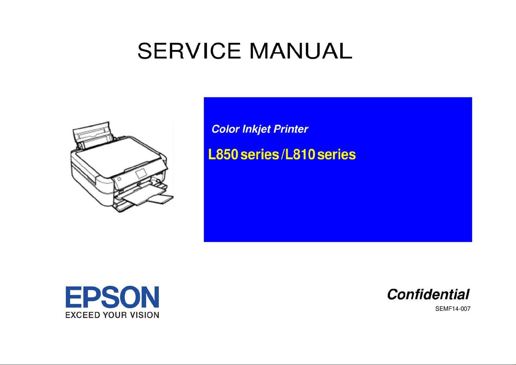
SERVICE
MANUAL
EPSON
EXCEED
YOUR VISION
Confidential
SEMF14-007
Page 2

Notice:
easyfixs.blogspot.com
• All rights reserved. No part
photocopying, recording,
The
•
• All effort have been made
•
EPSON is a registered trademark
General Notice:
Copyright©
contents
informed
The
above not withstanding SEIKO EPSO N CORPORATION can assume no responsibility for any errors
of
this manual are subject to change without notice.
of
them.
2014
or
to
Other product names used herein are for identification purpose only and may be trademarks
respective owners.
SEIKO EPSON
PRINTER
of
this manual may be reproduced, stored in a retrieval system,
otherwise, without the prior written permission
ensure the accuracy
of
SEIKO EPSON CORPORATIO
EPSON disclaims any and all rights
CORPORATION.
CS
QUALITY
of
the contents
ASSURANCE
of
this manual. However, should any errors be detected, SEIKO EPSON wou
N.
DEPARTME
of SEI
KO
in
those marks.
NT
or
transmitted
EPSON CORPORATION.
in
any form
in
this manual
or
or
by any means, electronic, mechanical,
or
the consequences thereof.
registered trademarks
of
ld
greatly appreciate being
their
Confidential
Page 3

PRECAUTIONS
easyfixs.blogspot.com
Precautionary notations throughout the text are categorized relative to I) Personal injury and 2) damage to equipment.
D
ANGE
R Signals a precaution which,
DANGER Heading
s.
if
ignored, could result in serious
or
fatal personal injury. Great caution should be exercised in performing procedures preceded by
WARNING
The precautionary measures itemized below should
Signals a precaution which,
if
ignored, could result
always be observed when performing repa ir/maintenance procedures.
in
damage to equipment.
DANGER
1.
ALWAYS DISCONNECT
PROCEDURES.
2. NO WORK SHOULD BE PERFORMED ON
TECHNICIANS IN THEIR LINE
3.
WHEN PERFORMING TESTING AS DICTATED WITHIN THIS MANUAL,
SO. WHEN THE POWER SUPPLY CABLE MUST BE CONNECTED, USE EXTREME CAUTION IN WORKING ON POWER SUPPLY AND OTHER ELECTRONIC
COMPONENTS.
4. WHEN DISASSEMBLING OR ASSEMBLING A PRODUCT, MAKE SURE TO WEAR GLOVES
THE
PRODUCT FROM
OF
WORK.
THE POWER
THE UNIT BY PERSONS UNFAM
SOURCE
AND
DO
PERIPHERAL DEVICES PERFORMING ANY MAINTENANCE OR REPAIR
ILI
AR WITH BASIC SAFETY MEASURES AS DICTATED FOR ALL ELECTRON ICS
NOT CONNECT
THE
UNIT
TO A PO
TO
A VOID INJURIER FROM MET AL PARTS WITH SHARP EDGES.
WER
SOURCE UNTIL INSTRUCTED
WARNING
l.
REPAIRS ON EPSON PRODUCT SHOULD
2. MAKE CERTAIN
EPSON PRODUCT HAS A PRIMARY AC
3. ALWAYS VERIFY THAT
CIRCUIT
4. IN ORDER
STRAPS,
5. REPLACE MALFUNCTIONING COMPONENTS ONLY WITH
OT
6. WHEN
PRODUCTS CONTAINING FLAMMABLE GAS
BOARDS AND/OR INDIVIDUAL CHIPS.
WHEN ACCESSING INTERNAL COMPONENTS.
HER NON-APPROVED COMPONENTS MAY DAMAGE THE PRODUCT AND VO
USING COMPRESSED AIR PRODUCTS;
TO
THAT
PROT
THE
SOURCE VOLT AGES
THE
EPSON PRODUCT HAS BEEN DISCONNECTED FROM THE POWER SOURCE BEFORE REMOVING
ECT
SENSITIVE MICROPROCESSORS AND CIRCUITRY, USE STATIC DISCHARGE EQUIPMENT, SUCH AS ANTI-STATIC WRIST
BE
PERFORMED ONLY BY
IS
THE SAME AS
RA
TING DIFFERENT FROM AVAILABLE POWER SOURCE, DO NOT CONNECT
THOSE
SUCH
AS AIR DUSTER, FOR CLEANING DURING REPAIR AND MAINTENANCE, THE USE OF
IS
PROHIBITED.
AN
EPSON CERTIFlED REPAIR TECHNICIAN.
THE
RATED VOLTAGE, LISTED
COMPONENTS BY THE MANUFACTURE; INTRODUCTION OF SECOND-SOURCE ICs
ID
ANY APPLICABLE EPSON WARRANTY.
ON
THE
SER
IAL NUMBER/RA TING PLATE.
IT
TO
THE
POWER SOURCE.
OR
REPLACING PRINTED
SUCH
IF
TO
THE
DO
OR
Confidential
Page 4

About This Manual
easyfixs.blogspot.com
This manual describes basic functions, theory of electrical and mechanical operations, maintenance and repair procedures
be
herein are intended for the experienced repair technicians, and attention should
Manual Configuration
This manual consists
CHAPTER I.PRODUCT DESCRIPTIONS
CHAPTER 2.0PERATING PRINCIPLES
CHAPTER 3.TROUBLESHOOTING
CHAPTER 4.DISASSEMBL
CHAPTER 5.ADJUSTMENT
CHAPTER 6.MAINTENANCE
CHAPTER 7 APPENDIX
of
six chapters and Appendix.
Provides a general overview and specifi
Describes the theo
product.
Describes the step-by-step procedures for the troubleshooting.
Describes
he
t
Provides Epso n-approved methods for adjustment.
Provides preve
approved lubricants and adhesives required for servicin g the product.
Provides
the
product.
the
ry
of elec
trical and mechanical operations
YI
ASSEMBLY
step-by-step procedures for disassembling and assembling
ntive maintenance procedmes and
additional info1mation for r
cat
ions
of
the product.
the lists
epa
ir and maintenance.
ofEpson-
given to the precautions on the preceding page.
Symbols Used in this Manual
Various symbols are used throughout this manual eith
ec
ific topic or to warn
Indicat
es
that is necessary to keep the product
of the
information on a sp
or
procedure
NOTE,
an action.
CAUTION, or
I
II
CAUTION
I
•
Indicates an operating
if not
that,
equipment.
May indicate an
condition that is nece
provide additional information that is related
co
mment on the results achieved through a prev
Be
WARNING messages.
an operating
str
of
the printe
aware
ictly observed, could result
ope
r.
The instructions and procedures included
of possible danger prese
of all
symbols when they are used, and always read
or
maintenan
or
maintenance procedure, practice,
rating
or
ssa
ry
to accomplish a ta sk efficiently. It may also
ce
's
maintenance procedure, practice
er
to provide additional
nt during a
proce
dur
e,
practice
quality.
in
damage to,
to
or
a spec.
i:fic
ious action.
or condition
or
condition
destruction of,
or
subject,
or
•
Indicates
that,
a
Indicat
standard after disassembly and before re-assembly,
ity
Dl
an
operating
if
not strictly observed, could result
es
that a particular task must be carried out according to a
of
the components in question may be adversely affected.
or
maintenan
ce
procedure, practice
in
injury or loss
otherwise
or
condition
of life.
cer
tain
the qual-
Confidential
Page 5
Revision Status
easyfixs.blogspot.com
~;;1w11
ASq:tembe•
Qfui@Mi
12, 2-014FITTtRe1eas
Confidential
Page 6
L850
easyfixs.blogspot.com
senes
·
,
/1810
set
1es
· ·
CONTENTS
Revision
A
Chapter I PRODUCT DESCRIPTION
I. I Control Panel ........................................................................................................ 9
1.1.l Operation Buttons & LED .................................. ....................................... 9
ED
1.1.2 Buttons & L
Functions ......................................................................... 9
Chapter 2 OPERA TING PRINCIPLES
2
.1
Overvi
ew
............................................................................................................
2.1.l
Printer Mechanism ...................................................................................
2.1.2 Scanner Mechanism
Power
-On
2.2
2.3
Printer Initialization ............................................................................................ 15
Sequence ...........................................................................................
................................................................................. 12
11
11
13
Chapter 3 TROUBLESHOOTING
3.1 Overview ............................................................................................................ 17
To
3.1.1 Specified
3.1.2 Preliminary Checks .............................................................................
3.1.3 Procedure for Troubleshooting ................................................................ 17
3.2
Troubleshootin g When
3.2.1 Error List ................................................................................................. 18
3.2.2 Warning List ............................................................................................ 19
FATA
3.2.3
3.3 Troubleshooting When
3.3.1 Troubleshooting for Printer .....................................................................
3.3.2 Power Supply R
3.3.3 Ink Supply Related Troubleshooting ....................................................... 33
3.3.4 I/F Related Troubleshooting ......................
3.3.5 Troubleshooting for Scann
Chapter 4
4.1 Overview ............................................................................................................ 38
4.1.l
4.1.2 Tools ........................................................................................................
4.1.3 Preparation b
DISASSEMBLY
Pr
ecautions ..............................................................................................
ols ........................................................................................
There
is Error Display .................................................. 18
L Error............................................
Ther
e is No Err
ela
ted Troubleshooting ..................................................
AND
efo
re Di sassembly .............................................................. 38
or
Display ............................................
..
............................................ 34
er
................................................................... 35
ASSEMBLY
....
17
17
22
28
28
32
38
38
4.1.4 Making a Special Tool for CSIC
4.1.5 How to
4.1.6 Checks and
4.1.7 Protection for Transportation .................................................................. 43
Packing methods ...................................................................................... 45
4.1.8
4.1.9
Di
4.2 Disassembly
4.2.1 Paper Support Assy .................................................................................
4.2.2 Stacker Cover ............................................................................. .............
4.2.3 Document Cover/A
4.2.4 Upper Housing/Scanner Cable Cover
4.2.5 Panel Unit ......................................................................................... ....... 56
4.2.6 M/B
EMI
4.2.7
4.2.8 Main Board Unit ............................................................................ ..........
4.2.9 Middle Housing ....................................................................................... 63
4.2.
IO
Disassembly
4.3
4.3.1 Adapter section ........................................................................................ 67
4.3.2 Ink Supply
4.3.3 Ink Supply Tank
4.3.4
Ink
4.4
Disassembly
4.4.1 Printhead ..................................................................................................
4.4.2 Linear S
4.4.3 Printer Mechanism .................................................................................. 77
PF
4.4.4
PF
4.4.5
4.4.6
Ink
4.4.7
ASF
APG
4.4.8
4.4.9
CR
4.4.10
4.4.1 I Paper Eject Frame Assy ........................................................................ 89
4.4.12
4.4.13 Front
Unlock the Carriage .................................................................... 39
Pre
caution s before Disassembling .......................................
sassembly and Reassembly Procedure ................................................
of
Exterior Parts ............................................................................
SF Cover
Cover
............................................................................................... 58
Frame/Waste Ink Tray Assy ........................................................... 58
Pow
er
Supply
of
Supply
the
Encoder/PF Scale ............................................................................... 79
Motor ...................................................................................... ............
System Unit.. .....................................................................................
Unit. ................................................................................................. 82
Unit ................................................................................................. 83
Motor
CR
Unit. ................................................................................................. 86
Upp
er
Pap
Paper Guide Assy ........................................................................ 92
Assy
............................................................................... 66
CISS section ............................................................................. 67
Tube
Assy section ................................................................. 68
Tube
Assy section ........................................................ 70
Tank
Assy section ................................................................. 71
Printer Mechanism .................................................................. 74
cale
.............................................................................................
................................................................................................. 85
er
Guides ............................................................................... 91
Boa
rd .................................................. 39
......................................... .........................
.....................................................
40
47
48
48
48
49
50
60
74
76
79
81
Page 7
L850 series/LS
easyfixs.blogspot.com
JO
series Revision A
4.4.14 Waste Ink Pad s ......................................................................................
Chapter 5
5.1 Adjustment Items and Overview ........................................................................
5.1.1 Servicing Adjustment Item List... ............................................................
5.1.2 Required Adjustments ............................................................................. 99
5.2 Adjustment by the
5.2.1 Touch
5.2.2 Touch Panel Operation Check ...........................................
5.3 How to judge print samples by using the adjustment program ........................ 104
5.3.1
5.3.2 Head angular adjustment
5.3.3 Bi-D Adjustment ...................................................................................
5.3.4
5.3.5
PG Adjustment ................................................................................................. 108
5.4
5.5 Banding Reduction System (BRS)
Correction . . .........
5.5.1 Overview ............................................................................................... 1
5.5.2 Adjustment Procedure ........................................................................... 112
5.6 Scanner Original Adjustment ...........................................................................
Chapter 6
ADJUSTMENT
Panel Unit exchange .......................................................... lOl
Panel Calibration ........................................................................
...
.................
Top
Margin Adjustment ........................................................................ 104
...
.................................
PW Adjustment/First D
PF Adjustment ....................................................................................... 107
..
. . . . . . ................ .................. ................ ................. .........
ot
Position Adjustment .................................... 106
Adjustment/Paper Feed Amount Profile (PFP)
...
................................ 104
..
. . . .
..
MAINTENANCE
94
96
96
101
101
10
......... I I 0
10
I
15
5
6.1 Overview .......................................................................................................... 1
6.1.1 Maintenance Error .................................................................. ............... 119
6.1.2 Cleaning ...............................
6.1.3 Lubrication ............................................................................................
Chapter 7
7.1 Exploded Diagram I Parts List ......................................................................
APPENDIX
...
............................................................... I I 9
...
19
I
20
127
Page 8

easyfixs.blogspot.com
PRODUCT DESCRIPTION
Confidential
Page 9

L850 series/L8JO series Rei·ision A
easyfixs.blogspot.com
1.1 Control Panel
1.1.1 Operation Buttons & LED
The
following
Button
LED* Power
tables
explain
Button/LED
Power Turns the power ON/OFF.
Home Goes
Crop/ Changes a display method.
Di
splay Options
Help Displays the help.
Menu Detailed settings.
Cross Keys
(up/down/left/
right)
OK Selects.
Back
Stop
Start
+
-
the
Ta
ble 1-
functions
1.
of
Operation Buttons & LED
I
10
home screen.
Crops photos.
Moves
the
cursor.
Cancels or goes back.
Cancels a job.
Resets 1he settings.
copy/print/scan.
Starts
Solves errors.
Increase or decrease the number
Turns on when the power is on.
Flashes while processing.
the
buttons
Function
and
of
LED.
prints.
1.1.2 Buttons & LED Functions
Detailed
Note : ---:No change
information
Printer
Idle mode Effective keys blink
Power-off OFF
Warning Effective keys blink
Fatal error Effective keys blink
Printing/Scanning Effective keys blink
Preparing FW update Effective keys blink
li
nk
B
Blink
se
of
I:
2:
Network
Displaying the screen-saver
Power save mode
Response
Airprint Identify-Printer
on
the
LED
functions
Ta
ble 1-2. Buttons & LED Functions
Status
tting Effective keys blink
I
are
Buttons
OFF
OFF
---
Repeats turning On and
Repeats turning On and
Off
every 1.25 seco nds.
Off
every 0.5 seconds.
listed
below.
P1mcr
I
LED
ON
OFF
---
Blink 2
li
nk I
B
Blink I
--
---
---
Blink2
Note * · See
PRODUCT
Tab
le 1-2 for more information on the LED.
DESCRIPTION
Figure 1-
1.
Name of Buttons & LED
Stop/Clear
butt
on
Control Panel 9
Confidential
Page 10

easyfixs.blogspot.com
OPERATING PRINCIPLES
Confidential
Page 11

L850 series/L8JO series Revision A
easyfixs.blogspot.com
2.1 Overview
Description in Table 2-2. Scanner Mechanism (
to LSI 0 series.
•
Thjs section describes the operating principles
L8
IO seri
es.
p.12)
of
the printer mechanism of L8
is n
ot
applied
50
serie
s/
I 0 C
11
CD
I 2 Ca
D-R
Gui
de
Sensor
-R Tray Sensor
se Open Sensor
ble 2-1. Motor
s and Sensors (
Functio
n:
De1ec1i
on method: Mechanical con1act detector
n:
Func1io
ec1ion method: Mec
De1
Function:
Det
ection method: Mechanical contact detector
Printer
CD-R Guide up/down detection
C
D-R
Tray pr
hm1i
cal contact de1ector
Scanner U
nit
ese
open/cl
Mechanism)
nce de1ec1i
ose
detection
on
Ta
2.1.1 Printer Mechanism
L850 series/LS I 0 seri
Tab
Prinihead
2
CR
Motor
3
PFM
otor
4 PE
Senso
r
5 CR
Co
ntact ModLlle
6 CR Encoder
7 PF En
8 PW Sensor
9 APG Sensor
co
der
es
are equipped with the following printhead, motors and sensors.
le 2-1. Motors
and
Sensors (
F3
-MA
CH Turbo 2 h
Type:
Voltage:
ra
cteristics: Annalllre res
Cha
Dri
ve system:
Typ
e:
Voltage:
Cha
ra
cteristi
Dri
ve
system: PWM
Func1io
n:
Detection metho
lnk canrid
Typ
R
Typ
R
Function • Paper le
De1ec1ion method: Reflecti
Function:
Det
eso
eso
e:
lutio
e:
lution:
ec
ge detecti
n:
tion metho
ead
(6
DC motor
42V D
C±
Induc
tan
PWM
co
DC mot
42V D
cs:
C±
Armature r
Inductance : 17.2 mH (I kHz)
sys
Detecti
on
posit
ioning co
d:
Transmissive-1
on (CSIC)
Transmissive-type photo-
180 pulse/inch
Tr
ansmiss
180 pul
se/inch
(before and during priming)
• P
ape
r top ed
• Pap
er
• CD-R top, bottom, right a
(before printing)
APG positi
d:
Transm
iss
Printer
co
ce : 17.5 mH ± 25%
or
bottom ed
ve pho1
Mechanis m)
lors x 90 nozzles)
5% (voltage applied to the driver)
istance : 22.7 n ± 10%
nstant-current chopping
5% (voltage applied to the driver)
esis
ta
nce : 2 1.2 n ± I 0%
tem
of the paper tail end, Pape
ntr
ol
ype pho10
ive-type photo-interrupter
fl and right edge
ge
(before priming)
ge
(during printing)
osenso
r
on detection
ive-type photo-
-in1
int
int
sys
errupter
errupter
nd
lefl ed
errupter
tem
r leading ed
ges
ge
Figure
2-1
. Motors
and
Sensors (Print
er
Mechanis
m)
OPER
1\ TING
PR/NCI
PLES
(h•eniew I I
Confidential
Page 12

L850 series/L8JO series Revision A
easyfixs.blogspot.com
2.1.2 Scanner Mechanism
L850 series is eq uipped with the folJowing CIS Unit, motors and sensors.
Table 2-2.
R
CIS Unit
2 CR Motor Voltage: 42V DC ±
senso
3 Encoder
r
eso
16
bit per pixel (input), 8 bit p
Type: DC mot
Drive
Type: Lin
eso
R
Scanner Mec hanism
lution: 10,200 pi
sys
tem: VrefpWM input
lution 180
ear encode
pulse
xel
er
pixel (o
utpu
or
5%
(voltage appli
constant-current chopping
r
/inch
t)
ed
to
the driver)
OPER
1\ TING
Figure 2-2. Motors a
PR/NCI
PLES
nd
Sensors (Scanner Unit)
I
Oi•eniew I 2
Confidential
Page 13
L850 series/L8JO series Revision A
easyfixs.blogspot.com
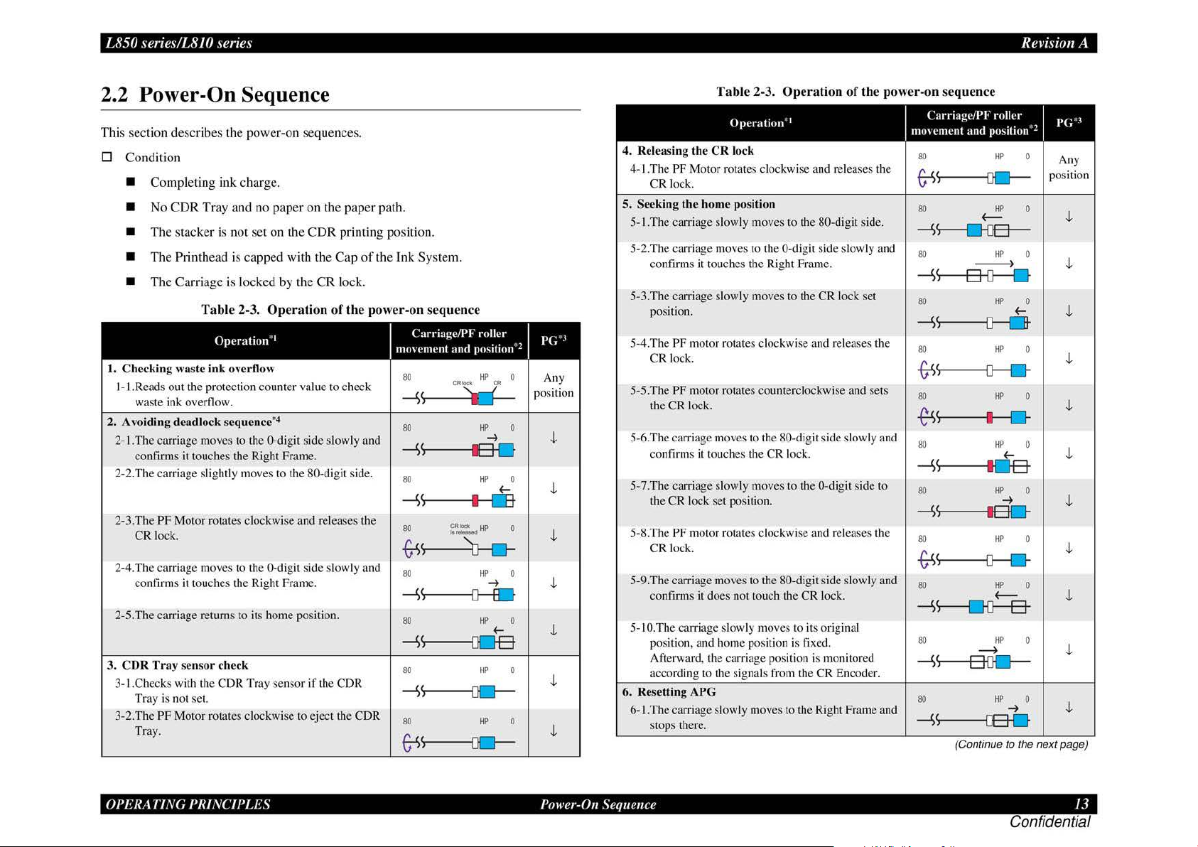
2.2 Power-On Sequence
This
section desc
D
Cond
•
Complet
•
No CDR
•
The stac
•
The Printhead is
•
The
I.
Checking waste
I- I .Reads out the protection count
waste ink overflow.
2. Avoiding
2-1.The carriage moves to the 0-digit side slowly and
confirms it touches the Right Frame.
2-2.The carriage slig
2-3.The PF Motor rotates clockwi
CR lock.
2-4.The carriage moves to the 0-digit side slowly and
confirms it touches the Right Frame.
2-5.The carriage returns to its home position.
3.
CDR
Tray sens
3-1.Checks with the C
Tray is not set.
3-2.The PF Motor rotates clockwi
Tray.
rib
es the
iti
on
ing ink
Tray and
ker
is
Carriage
Tab
Operation
ink
deadlock sequence
htl
or
check
pow
er-
on sequences.
charge.
no
pap
er on the
not
set
on the
CDR
printing position.
capped
is l
ocked
le 2-3.
overtlow
y moves to the 80- digit side.
DR
with
by
Operation
1
"
er
4
•
se
Tray senso
se
the
Cap
the
CR
lock.
of
value to ch
and releases the
r if the CDR
to eject the CDR
paper
path.
of
the
Ink
System.
the power-on sequence
I
Carriage/PF
eck
1110\c111ent
80
and
CRIOc•
-s~
80
-S'
I
80
-S'
I
80
trs
80
-s
80 HP 0
-s
80
-S
80
~
;~~
~
~
~
)-----{}0-
<,----{JO-
roller I
position"
HP 0
CR
HP 0
-+
EI
D
HP
0
f-
I
LE
0
HP
HP
0
-+
f-
HP 0
HP 0
2
p(;".I
Any
position
J,
J,
J,
J,
J,
J,
J,
Table 2-3.
Operation
4.
Releasing the
4-1.
Th
e PF Motor rotates clockwise and releases the
CR
Seeking the
5.
5-1.The
5-2.The carria
confams
5-3.The carriage slowly moves to the CR lock set
position.
5-
4.T
he
CR
5-5.The PF motor rotates counterclockwise and sets
the
5-6.The carria
confirms it touches the
5-7.The
the
5-8.The PF motor rotates clockwise and releases the
CR
5-9.The carria
confinns it does not touch the CR lock.
5-1
O.The
position, and home pos
Afterward , the carriage position is monitored
according to the sig
6. R
ese
tting APG
6- l.Th
ecarriage slowly moves to the Right Frame and
stops there.
CR
lock
lock.
hom
e position
car
ria
ge slow
ly moves to the 80-digit sid
ge
moves to the 0-digit side slow
it
touches the Right Frame.
PF
motor rotates clockwi
lock.
CR
loc
k.
ge
moves to the 80-digit side slowly and
car
riage slowly moves to rhe 0-di
CR
lock set position.
lock.
ge
moves to the 80-digit side slowly and
car
riage slowly moves to its original
Operation
1
"
se
and releases the
CR
lock.
iti
on is
fix
ed.
nal
s from the CR Encode
of
the power-on sequence
git
side to
Carriage/PF roller I
1110\c111ent
80
~
80
e.
-S
ly
and
80
-S
80
-S
80
-6:1>
80
~(
80
and position'
HP
~
HP
(--
s----£HJB-
HP
~
<,---a-{}----0
HP 0
s---D---CJ-
HP
~
HP
I
I
0-
HP
f-
p(;'.I
2
0
Any
posit-ion
0
J,
0
J,
f-
J,
0
J,
0
J,
0
J,
-S<,--------t[JB
80
-S'
I
80
-6:1>
~
80
-S
s------nD----8-
80
-S
r.
s----aoc;J-
80
10
~
HP
-+
0-
HP
HP
~
HP
HP 0
-+
0
t
0
J,
0
J,
0
J,
J,
-ss------os-o
(Continue
to
the next page)
OPER
1\ TING
PR/NCI
PLES
Power-On Sequence I 3
Confidential
Page 14
L
easyfixs.blogspot.com
5,1
senes
r ·
8
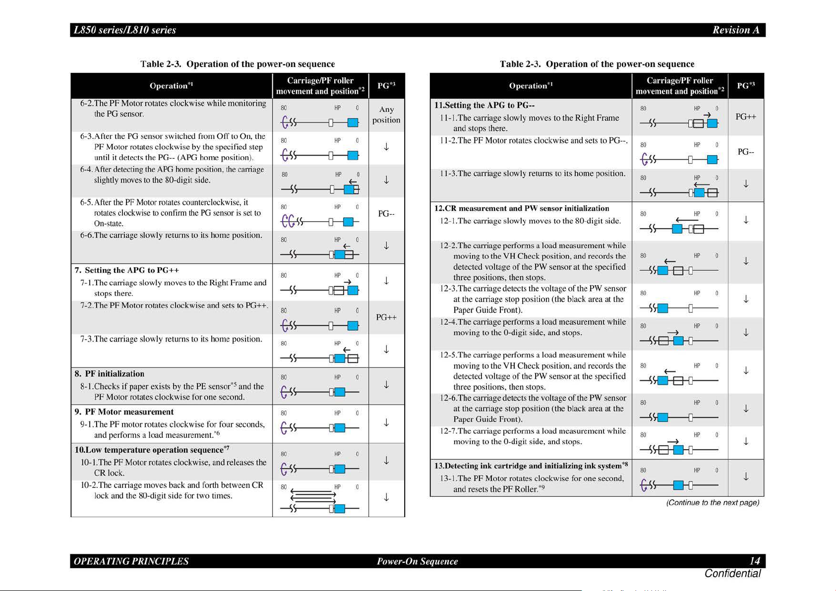
6-2.The
the PG sensor.
6-3.After the
PF Motor rotates clockwise by the specified step
until it detects the PG-- (APO home position).
6-4. After detecting the
slightly moves
6-5. After the PF Motor rotates counterclockwise,
rota1e
On
6-6.The carriage slowly returns to its home position.
7. Sett
7-.1.
The
stops there.
7-2.The
7-3.The carriage slowly returns to
8.
PF
initializat
8-1.Checks if paper exists by the PE sensor•5 and the
PF
PF
Moto
9.
9-LThe
and performs a load measuremen1.*6
10.L
ow
10-1.The PF Motor rotates clockwise, and releases the
CR lock.
10-2.The
lock and the 80-digit side for two times.
,
senes
/1810
PF
Motor rotates clockwise while monitoring
PG sensor switched from
s clockwise to confirm the
-stat
e.
ing the APG to
carriage slowly moves to the Right Frame and
PF
Motor rotates clockwise and $ets to PG++.
ion
MotOr rotat
r m
easurement
PF
motor rotates clockwise for four seconds.
temperature
ca
rria
ge
· Revision A
Ta
ble 2-3. Ope
Operation
APO
to
the 80-digit side.
PG++
es
clockwise for one second.
operation sequence
moves back and forth between CR
· 1
home
rat
ion of the power-on sequence
Off
to On,
posi1ion, 1he
PG
i1s
carriage
sensor is set to
home position.
"
it
1he
Carriage/PF
mo\cment
80
-s-s
~
80
trs
S---------U----
80
--'>
s---------o--rn
80
-e&i>
s----D---0--
80
--'>
s---rn:a-
80
-'>
<,----------QB-
80
trs
S------0----0
80
--'>
s-oc:JB
80
~
<,----------{)Q
80
and
roller
position"!
HP
0
HP
0
HP
0
(--
HP
0
HP
0
(--
HP
0
~
HP
0
HP
0
(--
Ill' 0
HP
0
J>(;".I
Any
posirion
.J,
.J,
PG--
.J,
.J,
PG++
.J,
.J,
.J,
~
~
,
HP
HP
0
.J,
0
.J,
80
~
s-----oc-
80
~
_i;
~
Tab
le 2-3. Op
Operation
11.Setting the APG to
I I-I .The carriage slowly moves to the Right Frame
and stops there.
J
1-
2.The
PF
Motor rotates clockwise and sets to PG--.
11
-3.The carriage slowly returns to its home position.
12.CR measurement a nd
12-1.The carriage slowly moves to the 80-digit side.
12-2.The carriage performs a load measurement while
moving to the VH Check position. and records the
detected vollage
three positions, then stops.
12-3.The carriage detects the
at the carriage stop position (the black area at the
Paper Guide Front).
12-4.The carriage performs a load measurement while
moving to the 0-digit side, and stop
12-5.The carriage perfo1ms a load measurement while
moving to the
detected voltage
thr
ee
positions, then stops.
12-6.
Th
e carriage detects the voltage
at
the carriage stop position (the black area at the
Paper Guide Front) .
12-7 .The carriage performs a load measurement while
moving to the 0-digit side, and stops.
13.Detecting ink cartridge
13-1.The
PF
Motor rotates clockwise for one second,
and resets the
PG--
PW
of
the
YH
Check position, and records the
of
the PW sensor at the specified
and
PF
Roller. •9
erat
ion of the power-on sequence
·•
sensor initialization
PW
sensor at the specified
voltage
of
the PW sensor
s.
of
the PW sensor
initializing ink system*
Carriage/PF
1110\ement and position' !
80
--'>
S---OS-O
80
trs
S------0---0
80
--'>
s------aoa
80
--'>
s------o-oa--
80
---'>
~
80
"'"""
~
80
--'>
SB-0-D----
80
--'>
s.o-a--o----
80
---'>
~
80
---'>
~
8
80
-&s
s----n-o---
(-----
~
~
~
~
(Continue
roller
HP
HP
HP
(---
HP
HP
HP
HP
HP
HP
HP
HP
0
~
0
0
0
0
0
0
0
0
0
0
to
the next page)
p(;'.I
PG++
PG--
.J,
.J,
.J,
.J,
.J,
.J,
.J,
.J,
.J,
OPER1\TING
PRINCIPLES
Power-On Sequence
14
Conf1dent1al
Page 15

L850 series/L8JO series Revision A
easyfixs.blogspot.com
Tab
le 2-3.
Operation
Operation
J 3-2.The carriage slowly moves
13
-3.T
he
carriage
the ink end sensor. The ink remaining is detected
after
comp
13-4.The carriage slowly returns
14.
CR lock
1
4-1.The
carriage slow
position.
14-2.The
14-3.
Note
PF
the
CR
The carriage sl
*I:
The
Clockwise: Paper is fed normally
Counterclockwise:
*2: The
Red:
Whit
*3:
lndicates the PG position. "Any position" means that the PG position is not
recognized because
*
4:
Checks
*5:
Eject the
*6:
When paper exists, the existing m
therefore, the
*7: Executes
*8:
The empt
*9:
ff
mov
leting tbe check.
setting
Motor rotates counterclockwise, and sets
lock.
owly
rotation
direction
condition
CR
Jock is
e:
CR
lock is released
if the carri
paper
when the detected temperature
y suction operation may occur depending on 1he situation.
paper re
main
· 1
to
es
to
the 80-digit side to chec k
to
ly moves to the
returns to its h
of
th
Paper is fed backward
of
the
CR
lock is
set
APG is not reset yet.
age
is
not deadlock such
if
any.
PF Motor
s in
does
1he
primer, !he PF
of
the power-on sequence
the 0-digit side.
its
home
position.
CR
lock
set
ome
position.
e
PF
Motor
is as
as
fol.lows.
as
eas
urement value saved in EEPROM is read out;
not rotate.
is
under 5 °C (41
Roll
er
rotates
Carriage/PF
mo\cment
80
~
s--a::n----
80
<
~
c,.o-ao--
80
~
s-a----ab-
80
~
s-----oao-
80
~s
80 HP 0
--
and
~
roller
position"!
HP
HP 0
HP 0
HP
~
HP 0
I D-
~
~s--------tDB
follows.
the
CR lock
is
caught in the gap
°F)
by the thennistor
by
steps enough
10 ejec
t lhe paper forcibly.
J>(;".I
0
PG--
.J,
.J,
0
.J,
.J,
.J,
of
the carriage.
on the Printhead.
2.3 Printer Initialization
Th
ere are
fom
kinds
of
initialization method
initialization.
1.
Hardware initialization
This
print
er
is initialized when turning the printer
the cold-reset command (remote
When printer is initialized, the following actions are performed.
(a) Initializes printer mechanism
(b) Clears input
data
buffer
(c) Clears print buffer
(d) Sets default values
2. Operator initia
li
zation
Initialization when resetting the
(a) Clears input data buffer
(b) Clears print buffer
(c)
Set
s default values
3. Software initialization
The
ESC@command
also initialize the printer.
When printer is initialized, the following actions are performed.
(a) Clears print
(b)
Sets default values
4.
IEEE
1284.4 "r
The
printer recognized the IEEE 1284.4 "r
When print
• Initializat ion when an
buff
er
s"
command
er
is initialized, the following action is performed.
initialization
e1Tor
(a) Initializes printer mechanism
(b) Clears input data buffer
(c) Clears print buffer
(d) Sets d
efa
ult values
• Initialization in normal operation
(a) Clears input data buffer
(b) Clears print buffer
(c)
Sets default values
, and the following explains each
pow
RS command) .
USB
sof
tware, and the following are performed.
s"
command.
occurs.
er on,
or
printer recognized
OPER1\ TING
PR/NCI
PLES
Printer lnitiali:.atio11 I 5
Confidential
Page 16

easyfixs.blogspot.com
TROUBLESHOOTING
Confidential
Page 17
L850
easyfixs.blogspot.com
series/L8JO series
Rei
·isio
11
A
3.1 Overview
Description in this c
But
3.2.3.1
Scanner
series.
•
This chapter describes troubleshooting.
3.1.1 Specified Tools
L850 series/LS I 0 series does not require any specified tools for troubleshooting.
3.1.2
Before starting troubleshooting, be sure to verify that the following conditions are a
Preliminar
•
The
power
the voltage at
•
The
POWER
miswiring
•
The
Unit must
•
The
Unit should
or
low temperature, too high
•
The
Unit should not be located near waterworks, near humidifiers, near
heaters
or
be
exposed to blast from an air conditioner.
•
The
Unit should not be located
are produced.
•
The
Unit should not
rays
of
the sun.
•
The
Unit must be placed on a strong and steady level table (without an
inclination larger than 5 degrees).
•
There
must be no vibration generating source placed
•
The
paper used must conform to the specification.
•
There
must be no error in handling
•
Check the inside
clips, staples, bits
• Clean
the
y Checks
supply voltage must
the
wall outlet.)
CORD
in
the POWER CORD.
be
grounded properly.
not
near flames, in a dusty atmosph
of
of
inside
of
hapt
er is applied
FATAL E
be
within the specification limits.
must be free from damage, short circuit
be
located
be
the Unit, and remove foreign matters,
paper, paper dust
the Unit and the rubber rolls.
in a place
or
low humidity,
in
a place where volatile
located in a place where it
of
rror
s (
where
ere
the Unit.
or
toner.
to
L850 series/L810 series.
p.22
) is not applied to L810
it
can
be
or
abrupt temperature change.
or
in
a place where the Unit can
can
be exposed to direct
in
(Measme
or
breakage,
exposed
or
contact with this Unit.
if
to
too
inflammable gases
any, such as paper
ll
high
met
or
3.1.3
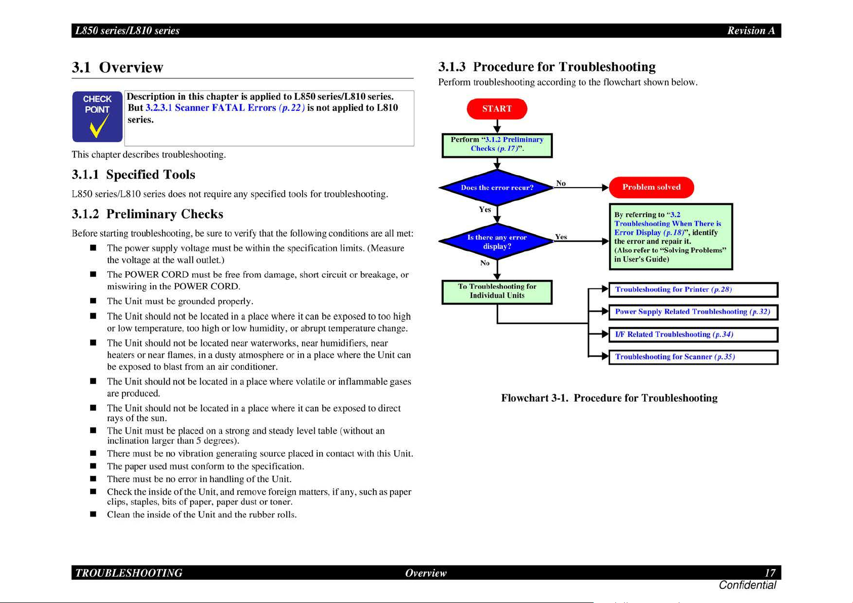
Perform troubleshooting according to the flowchart shown below .
Procedure
Perfo
rm
"3.1.2 Preliminary
Che
ck
To T
ro
ubleshooting for
individual
s (p .
17)".
Units
Flowcha
for Troubleshooting
No
Yes Error
• l..:;.::;:....
rt
__
3-1.
Procedure for
Problem
By
referri
Troubleshooting When There is
--11~
th
(Also refer to "Solving Problem
in
Troubles
Power Supply Related Troubleshooting (
I
Tr
ng
Display (p.18)
e error and repa
User's Guide)
ho
/F
Relat
ed Troubleshooting (p
oubleshooting for Scann
Troubl
solv
ed
to
"3.2
oting for
eshooting
",
ir
it.
Prin
identify
ter (p. 28)
er ( p. 35)
s"
.3
4)
p.
32)
TROUBLESHOOTING
Overview
17
Confidential
Page 18
L850 series/L8JO series
easyfixs.blogspot.com
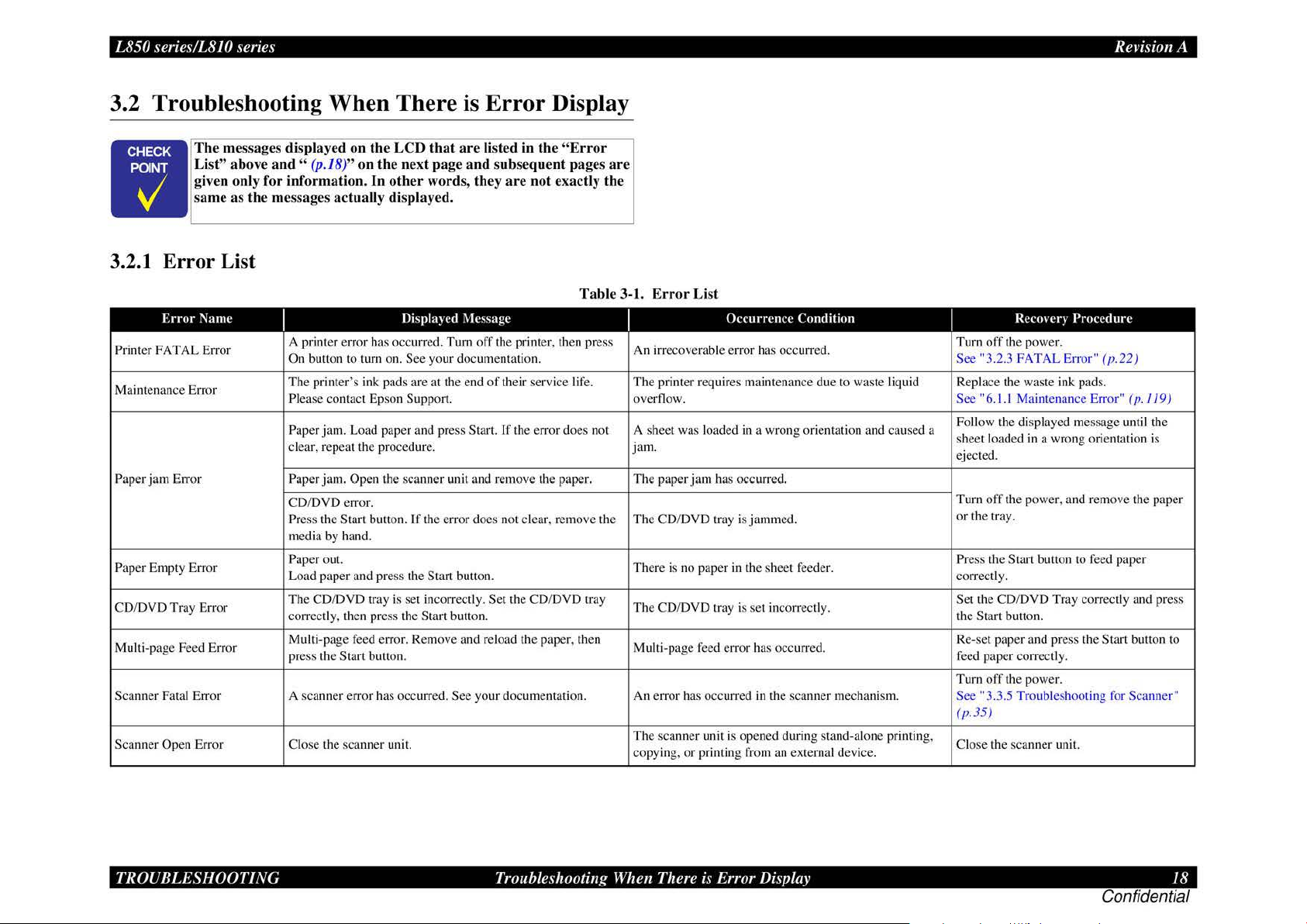
3.2 Troubleshooting When There is Error Display
Th
e messages displayed on the LCD
abo
List"
ve
n only for information.
gi
ame as
s
the messages actually displayed.
•
3.2.1 Error List
ve
and
" (p.18)" on the next page and subs
In
that are listed in th e "Err
oth
er word
s, they
equent
are
not exactly the
or
pages are
Rei
·isio
11
A
Error
Name
Printer
FATAL Error
Maintenance Error
Paper
jam
Error Paper jam. Open tbe scanner unit and remove the pape r. The paper
Paper Empty Error
CD/DVD Tray Error
Multi-page Feed Error
Scanner Fatal Error A scanner error has occurred.
Scanner Open Error Close the sca nn
I
A printer error has occurred. Turn
On button to turn on. See your documentatio
The
printer
's
Plea
se
contact Epson Support.
Paper jam. Load paper and press Start.
clear, repeat the procedure.
CD/DVD error.
Press the Start burton.
media by hand.
Paper out.
Load paper
The CD/DVD tray is set incorrectly. Set the CD/DVD tray
correctly, then press the
Multi-page feed error. Remove and reload the paper, then
press the
and press the Start button.
Start butto
Displa~
ink pads are at the end
If
the error does not clear, remove the
Start bullon.
n.
er
unit.
ed
\lessage
off
the printer, then press
of
their service li
If
See
your documentatio
n.
the error
Table 3-1. E
fe.
does n
ot
n.
rror
List
I
irrecoverable error has occurred.
An
The
printer requires maintenan
overflow.
A sheet was loaded
jam.
The
CD/DVD tray is jammed.
Th
ere is no paper
The
CD/DVD tray is set incorrectly.
Mu
lti-page feed err
An error has occurred in the scanner mechanism.
The
sca
nner unit is opened during stand-alone printing,
copy
in
g,
Occurrence
in
jam
has occurred.
in
the sheet feeder.
or
or
printing from an external device.
Condition
ce
due to waste liquid
a wrong orientation and caused a
has occurred.
Reem
er~
I
Turn
off
the power.
See
"3.2.3 FATAL Error"
Replace the waste ink pads.
See "6.
1.1
Maintenance Error"
Follow the displayed message until the
sheet loaded in a wrong o
ejected.
Turn o
ff
the power, and remove the paper
or
the tray.
Pr
ess the Start button to feed paper
cor
rectly.
Set the CD/DVD Tray
the
Start button.
Re-set paper and press the
feed paper
Turn
See
(p
.35)
Clo
correctl
off
the power.
"3.3.5 Troubleshooting for Scanner"
se
the scanner uni
Procedure
cor
y.
t.
(p
.22)
(p
.119)
ri
entation is
rectly and press
Start button to
TROUBLESHOOTING
Troubleshooting When There
i~
·
Error Display 18
Confidential
Page 19
L850 series/L8JO series
easyfixs.blogspot.com
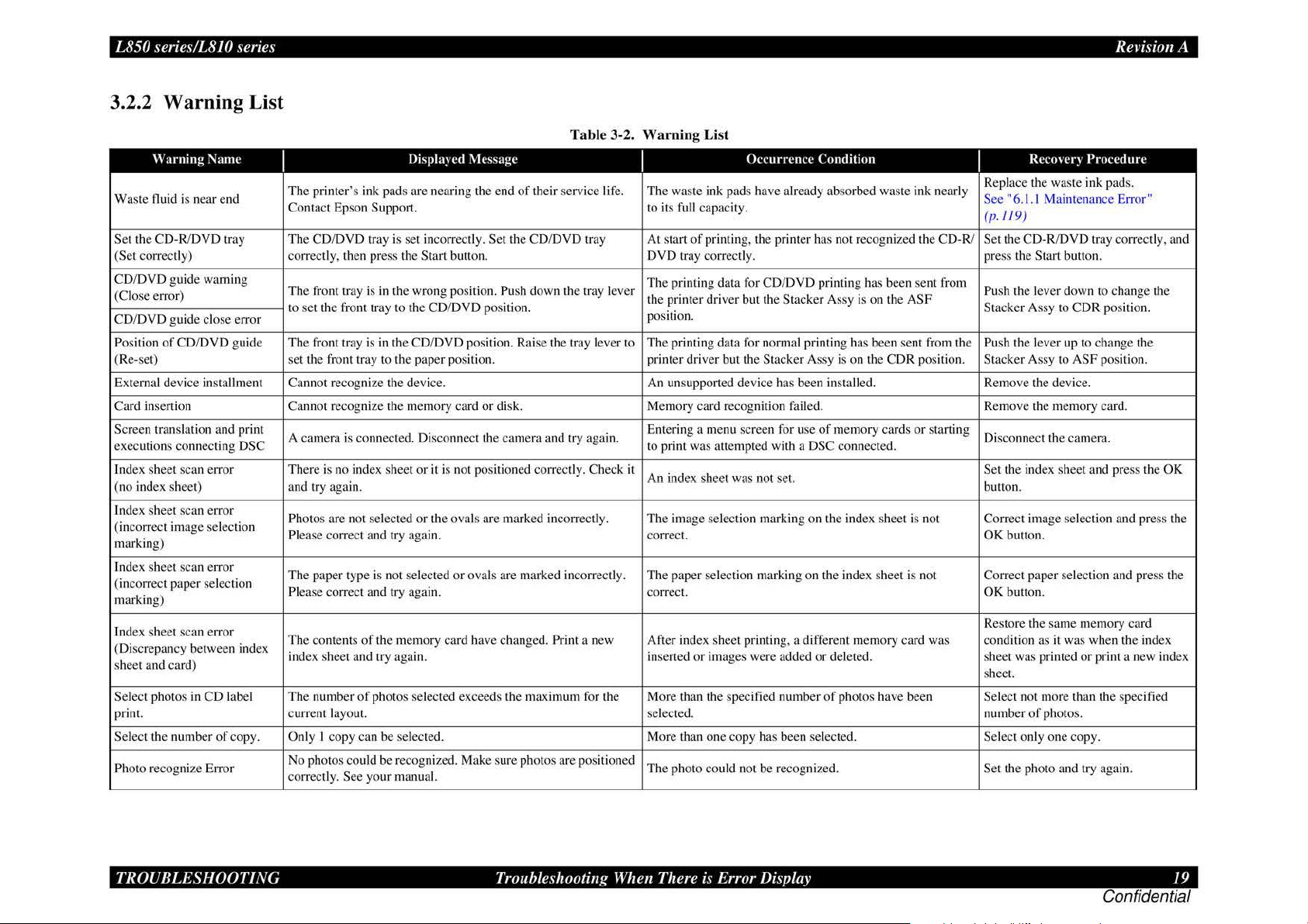
3.2.2 Warning List
Table 3-2. Warning List
Warning
Waste fluid is n
S
et
the CD-R/DVD tr
(Set correctl
CD/DVD g
(C
lose error)
CD/DVD guide cl
Position
of CD/DVD guide
(Re-set)
External d
inserti
Card
Screen translation and print
exec
uti
ons conn
Index sheet scan error There is no index sheet or it is not positioned correctly. Check it
(no index sheet) and try again. button.
l.ndex sheet scan error
ec
(incorr
marking)
index sheet scan error
incorrect paper selection
(
marking)
Index sheet scan error
(Di
sc
repancy between index
sh
ee
t a
nd card)
Select phot
print. current
Select the number
Ph
oto recognize
Name
ea
r end S
ay
y)
ui
de
warning
ose
error
evice installm ent
on Cannot r
ect
ing DSC to print was attempted with a DSC connected.
t image selecti
os
in CD label
of copy. Only I copy can be selected. More than one copy has been selected. Select only one cop
Err
or
I
The pr
Co
The CD/DVD tray is set incorrectl
correct
The front tray is in the wrong positio
to
Th
se
Ca
A camera is
Ph
on
Pl
Th
Please
The
index sheet and try
Th
No photos
corr
l>ispla~
l'd i\
kssage
inter
's ink pads are nearing the end
ntact Epson Suppo
ly, then press the Sta rt button. DVD tray correctl
se
t the front tray to the CD/DVD positio
e front tr
ay
t the fro
nt
tray to the paper position. printer driv
nnot recogni
ecognize
co
otos are not selected or the
ease correct and try again.
e paper type is not selected or ovals are marked inco1Tectl
correct and try again.
contems of the memory card have changed. Print a new After index sheet printin
e number of photos selected exceeds the maximum for the More than the specified number
layout.
co
uld be recognized. Make sure photos are positioned
ectly. See
rt. to its
is
in
the CD/
DVD
positio
ze
the device. An unsupport
the memory card or disk. Memory card recognition failed. Remove the memory card.
nnected. Disconnect the
ova
ag
ain.
your manu a
l.
of
their servi
y. S
et
the CD/
DVD
tray At start
n.
Push down the tr
n.
n.
Rai
se
the t
ray
came
ra and try aga
ls are marked incorrectl
ce life
ay
I
. The waste ink pads have already absorbed waste ink nearl
full capacity.
of
The printing data for CD/
lever
the printer driver but the
positio
n.
lever to
y.
Th
e printing data for normal printing has been sent from the
Entering a menu screen for u
in.
An ind
ex
The im
age selection marking on the index sheet is not
correc
t.
y.
The paper
correc
t.
inserted or images were added or deleted. sheet was printed or print a new index
selec
ted. number of photos.
Th
e photo could not be recognized.
Occurrcnn· Condition
printing, the printer has not recognized the CD-R/ Set the CD-R/DVD tray correctl
y.
DVD
Stacker Assy is
er
but the Sta
ed device
sheet was
se
lection marking on the index sheet is not
cker
has been installe
se
not
set.
g,
a different memory card was
printing has been sent from
on
the ASF
Assy is on the CDR positio
d.
of
memory cards or starting
of
phot
os
have been Select not more than the specified
I
pl
Re
y
ee
(p
.
11
press the Start button.
Push the lever down to change the
Sta
cke
Push the lever up to chan
n.
Stacker Assy to
Remove the device.
Di
sconnect the camera.
Set the index sheet and press the
Correc
OK
Correc
OK
es
R
co
ndition as it was when the index
sh
ee
Se
t the photo and try again.
Rei·isio11
Rcl'oHr~
ace
the was te ink pads.
"6.
1.1
9)
r Assy to CDR positio
t image selection and press the
button.
t paper selection and press the
butto
n.
tore the sa
t.
Procedure
Maintenan
ASF pos
me
memory card
ce
Error"
n.
ge
the
ition.
y.
A
y, and
OK
TROUBLESHOOTING
Troubleshooting When There
i~
·
Error Display 19
Confidential
Page 20

L850 series/LS
easyfixs.blogspot.com
JO
series Revision A
Table 3-2.
Warning
Scan to memory error
(no card) attempted with no memory card inserted.
Scan to memory error There is not enough free space on the memory card
(insufficient card capacity) canceled. sufficient capacity.
Scan to memory error
(card write-protect) save data. protected.
Scan to memory error Cannot create a folder on the memory card
(folder not created)
Scan to memory error
(card removed) been removed.
Scan to memory error
(save error)
Format check (backup)
Format check (scan)
Format Warning
(Format error) (scan) out the media while formatting it.
Format Warning
(card write-protect) (scan) protected and try again.
Format Warning
(card removed) (scan)
Head Cleaning Replace ink Adapter before cleaning print head. Head cleaning was attempted in the Ink Low state.
Backup error External device
(no external connection) Backup canceled. started.
Backup error
(insufficient external media
capacity)
Backup error
(insufficient memory card
capacity)
Backup error (no card)
Backup error
(File name and Folder levels
Error)
l\ame
I
No
memory card
The memory card
canceled.
The memory card
An
error occurred while saving. Save canceled. Data saving was not achieved for some reason. Check the source data
Cannot recognize the memory card
format it?
A problem occurred while formatting . Formatting canceled.
The memory card
The memory card or disk was removed. Format canceled. The media is removed when formatting is to be started. Insert media and try again.
Insufficient space on the backup device. Cannot back up files.
No memory card
Backup canceled. File name is too long
folder levels. levels
Displa)ed
or
disk inserted.
or
disk is write-protected. Operation canceled.
or
disk was removed. Operation canceled.
or
disk is write-protected. Operation canceled. As the memory card was write-protected, formatting failed.
is
not connected
in
slot. Backup canceled.
:\lessage
Save
canceled.
or
disk. Operation
or
disk.
Do
you want to
or
media is not inserted.
or
there are too many The file name is too long,
or
disk. Save
Warnin
g List (continued)
I
Execution
The
memory card capacity is insufficient.
As
the memory card is write-protected, it is not possible to Insert a memory card not write-
A folder could not be created
Data saving was not executed, since the memory card had
The
media for backup cannot be recognized.
The memory
An error has occurred
The
external device was not connected when backup was
The capacity
saved is insufficient. space.
No
backup sour
in
folder hierarchy. hierarchy.
Occurrence
of
scanning to a memory card function was
ca
rd cannot be recognized.
in
of
the media on which the backup data is to be Insert media that has sufficient free
ce
exists. Insert the memory card.
Condition
on
the memory card. Check the data on the memory card.
formatting the card.
or
the source has eight
Or
you pulled Press the
or
I
Insert a memory card.
Insert a memory card.
Execute
Cancel the head cleaning,
the ink Adapters.
Connect the external device.
more Check the file name and the folder
RecO\er)
Insert a memory card that has a
or
OK
media.
Insert a memory card not write-
Procedure
cancel formatting.
button and check the
or
media.
or
replace
TROUBLESHOOTING
Troubleshooting When There is Error Display
20
Confidential
Page 21

L850 series/LS
easyfixs.blogspot.com
Warning
Backup error
In adjustment
expansion value border may appear around your photo. Borderless Expansion Value.
JO
series Revision A
Ta
l\ame
of
borderless You can change the amount
I
Backup Error.
or
Code FFFFFFFF*
Err
Displa)ed
of
ble 3-2. Warnin
:\lessage
image expansion, but a white This message is always displayed during adjustment
g List (continued)
I
An error has occurred at the external device. Check the external device.
Occurrence
Condition
of
the
I
Accept it.
RecO\er)
Procedure
* · The actual messages are displayed as error codes corresponding to the cause
Note
of
the error.
TROUBLESHOOTING
Troubleshooting When There is Error Display 21
Confidential
Page 22
L850 series/L8JO series
easyfixs.blogspot.com
Rei·isio11
A
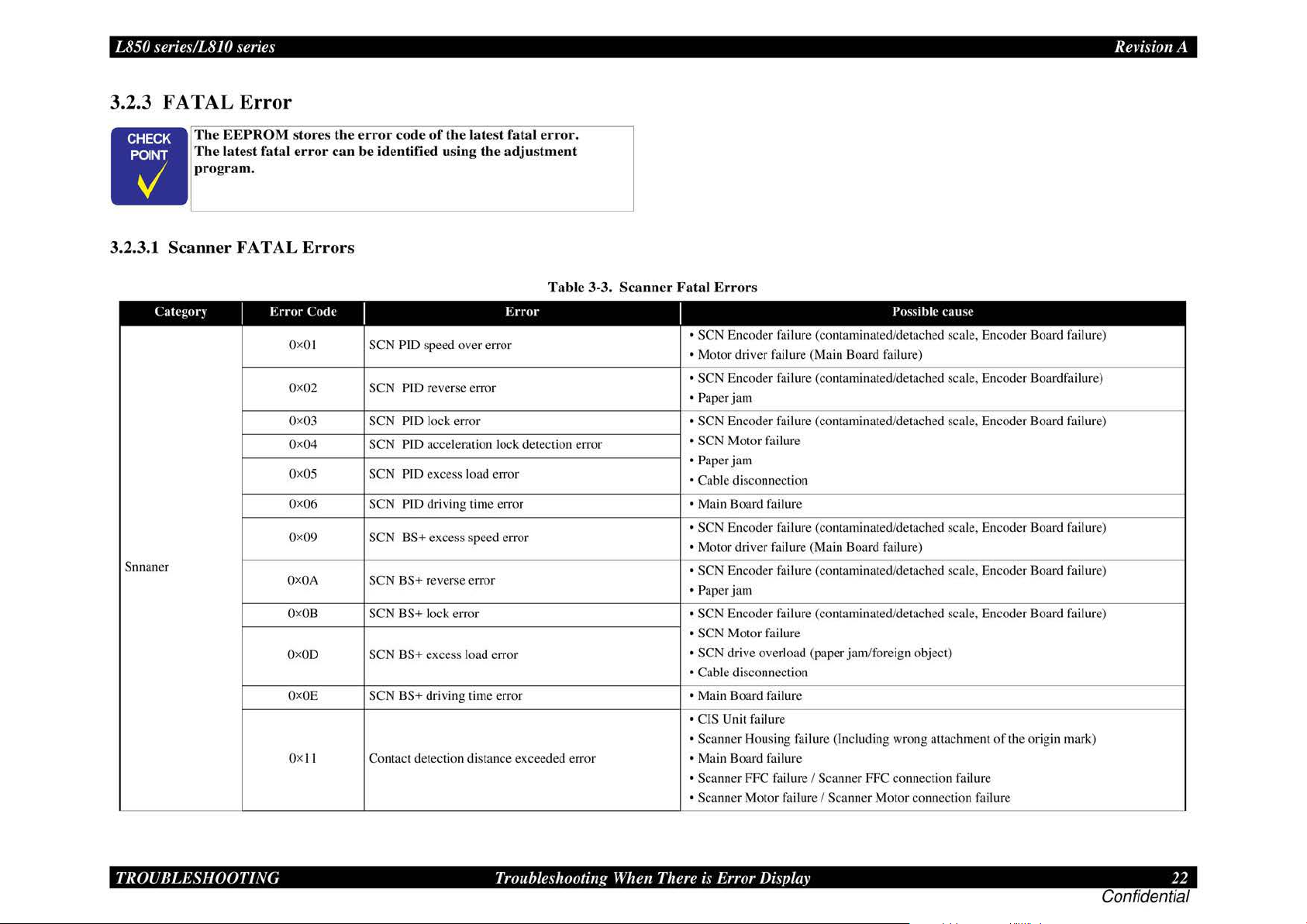
3.2.3
FAT
AL
Error
The EEPROM
The
latest fatal e
program.
•
3.2.3.1 Scanner FATAL
l'ategor~
Snnaner
I
E
rror Code
OxO
Ox02
Ox03
Ox04 SCN PID acceleration lock detection error
Ox
Ox06
Ox09
OxOA
Ox
OxOD
Ox
Qx
stores the e
rror
rror
code
of
the
can be identified using the
Errors
I
I SCN PID speed over error
Pill
reverse error
PIO lock error •
PID excess load error
PID driving time error • Main Board
BS+ excess speed error
ntact detection distance exceeded er
OS
OB
OE
l I
SCN
SCN
SCN
SCN
SCN
SCN BS+ reverse error
SCN BS+ lock error • SCN En
SCN BS+ excess load error
SCN BS+ driving time error • Main Board failure
Co
lat
est fatal e
adj
ustment
Erro
r
rror.
Tab
le 3-3.
ror
Scan
ner Fatal Error
s
I
• SCN Encoder failure (contaminated/detached scale, Encoder Board
• Motor driver failure (Main Board failure)
• SCN En
• Paper jam
• SCN Motor
• Paper
•
• SCN Encoder failure (contaminated/detach
•
• SCN
• Paper jam
• SCN Motor
• SCN drive overload (paper
• Cabl
• CIS Unit failure
• Scanner Housing failure (Incl
• Main Board failure
• Scanner FFC
• Scanner
coder
SCN Encode
jam
Cab
le disconnection
Motor
driver failure
Encoder
coder
e disconnection
Motor
failure (contaminated/detached scale, Encoder Boardfailure)
r fail ure (contaminated/detached scale, Encoder Boiu·d
fai
lure
fai
lure
(Ma
in Board failure)
fai
lure (contam inated/detached scale, Encoder Board failure)
failure (contaminated/detached scale, En
fai
lure
jam
fai
lure I Scann
failure I Scanner Motor connection
Possihle
/foreign object)
uding wrong attachment
er
FFC connection failure
cau
se
ed
scale, Encoder Board failure)
coder
Board failure)
of
the orig
fai
lure
in
fai
lure)
fai
lure)
mark)
TROUBLESHOOTING
Troubleshooting When There
i~
-
Error Display 22
Confidential
Page 23

L850 series/LS
easyfixs.blogspot.com
Categtir)
Snnaner
JO
series Revision A
Tab
I
Error
Code
Oxl2
Oxl3
Ox20 LED light error
I
Opposite side contact detection distance • CIS Unit failure
exceeded error
Opposite side wrong contact detection • CIS Unit failure
distance error
le 3-3. Scan n
Error
er
Fatal Errors
I
• Scanner Housing failure (Includ ing wrong attachment
• Main Board failure
• Scanner FFC failure I Scanner FFC connection failure
• Scanner Motor failure I Scanner Motor connection failure
•S
canner housing failure (Including wrong attachment
Main Board failure
•
• Scanner FFC failure I Scanner FFC connection failure
• Scanner Motor failure I Scanner Motor connection failure
• CIS Unit failure
• Main Board failure
Possible
cause
of
the origin mark)
of
the origin mark)
TROUBLESHOOTING
Troubleshooting When There is Error Display 23
Confidential
Page 24

L850 series/L8JO series
easyfixs.blogspot.com
Rei·isio11
A
Table 3-4.
Catcgor~
DC err
(C
R motor) motor operating sequence
or
I
Error
Code
I
OxO
J CR PID speed over err
Ox02
Ox08 CR PlD rever
OxOA
OxOB
oxoc
OxOD
CR load positioning lock error
CR load positioning accumulation moving • PF Adjustment
distance error
CR load positioning speed over error
CR
CR PlD
PTD
lock error
aveT
Error
or
se
rotation detection error
i max error
I
An error occurr
Printer
Cause
ed
Mechanism
in the CR
3.2.3.2 Prin
ter
Mechanism FAT AL Err
Fatal Errors
I
D Checking the operation
Move the CR
D
Making the followi.ng adjustments:
• Bi-D Adjustment
• PW Adjustment
D Checking t
• Checking the head FFC (CN 10/11/12) for disconn
• Checking the lead wires
• Checking the
• Checking
• Checking the CR Guide Shaft for adhesion
• Checking the Linear Scale for adhesion
• Checking the CR Encoder for adhesion
• Checking the PW Sensor for adhesion of dirt or damage
• Checking the CR Belt for damage
• Checking the
• Main Board (p.66)
• Power Supply Board (p.66)
Uni! by hand, and check to see if it moves smoothly.
he foll
CR
the printer frame for adhesion
CR
of
the CR Unit:
owing parts and replacing the defective
of
the CR Motor (CN 14) for disconnection
Encoder FFC (CN I6) for disconnection
Motor and replacing it if necessary (p.85)
Remed~
of
dirt
of
of
dirt
of
dirt
or
improper tension (p.85)
ors
one
ect
ion
or
breakage
or
breakage
or insufficient lubricati
dirt
or
insufficient lubrication
or
damage (p.
or
damage ( p. I
(p
76)
I)
. I I)
or brea
on
kag
(p
e
. 123)
(p
.122)
TROUBLESHOOTING
Troubleshooting When There
i~
·
Error Display 24
Confidential
Page 25

L850 series/L8JO series
easyfixs.blogspot.com
Tab
le 3-4.
Cakgor)
DC
error
(PF motor) motor operating sequence
A
PG
Motor drive
time error
motor
I
Error
Code
I
OxFB
Ox
OxFC
OxFA
OxEF Position error
OxFO
Ox70 APG error (normal drive error)
Ox71
Ox72
OxDJ CR (PID) drive time-out
OxD2
OxD3
OxD4
PF
acceleration lock error
FE
PF
speed over error insp
Measurement value error
limiting control
DTY
_max error
APG home seek
Error in APG drive by
CR
(load positioning) drive lime-out
PF
(PID) drive time-out
PF
(BS) drive time-out
Error
in
PF
BS control
in
PF BS control
e1Tor
in
PF
Duty
fac
tory command
Prin
ter Mec
I
An error occurred in the
An error occurred in the
APG operating sequen
The
motor kept operating
for more than
e.
tim
hani
Cause
the spec
sm
Fata
l Errors (continued)
Remed)
D Checking the
Check the
ect
D Ch
ecking the operation
Operate the
D Making the following adjustments:
Bi
-D Adjustment
•
PF
Adjustment
•
PF
• PW Adjustment
D Checking
• Checking the
• Checking the
• Checking the
• Checking the PF encoder for adhesion
• Checking the Upper Paper Guides for improp
• Ch
ecking the
• Main Board
• Power Supply Board (p.66)
0 Ch
ec
position
D Check
• Insta
ll
• Standalone
• Rein stallation of the
D Checking the following parts and replace the defective one:
ce
ified
• APG
• ASF Unit (p.82)
• APG
• PG L
• Main Board (p.66)
• Power Supply Boa
Checking the mechanism and operation:
D
Check the mechanism and operation
Checking the conn
D
0 Checking the motor in
• Main Board
• P
ower
PF mechanism
PF
mechanism for paper
ion.
PF
mechanism
the follow
king the installation
of
the sensor and connection
in
g t
he
ati
on
operation
Unit (p.83)
Sensor(p.
eft Cam (p.86)
Supply Board (
ing par
PF
Encoder FFC (CN8) for disconnection
lead wir
PF
scale for adhesion
PF
Motor and replacing it
(p.66)
drive
of
of
the composite
11)
.
rd
ect
(p.66)
by
visual inspection:
jam
or adhesion
of
the
PF
mechanis
by
hand , and check to see if it operates smoothly.
ts
and replace the defective one:
es
of
the
PF
Motor (C N 1
of
dirt or damage (p.
of
dirt
if
of
the APG Sensor:
of
the connector (CN7)
the APG Unit:
gear of
the ASF Unit - APG Unit
of
the APG Unit
APG Unit (phas
(p. 66)
ion
of
the connectors and routing
qu
estion and the following parts and replacing the defective part:
p.
66)
e)
of
the motor
of foreign mailers by visual
m:
or
3) for disconnection
or
dam
age
er
installation (p. 91)
necessary
(p
. 79)
in questio
of
breakage
or breakage
79)
(p.
79)
n.
the lead wires
Rei·isio11
A
TROUBLESHOOTING
Troubleshooting When There
i~
·
Error Display 25
Confidential
Page 26

L850 series/L8JO series
easyfixs.blogspot.com
Cakgor)
Factory
command
error
I
Error
Code I
Ox30
Ox40
Head system
error
Ox41
Ox42
Ox43
ox
so Home seek error
oxs1
Sequence
error
Ox52
Ox53
Ox56
Ox60
Ox6J
Sens
or
error
Ox62
Ox63
Tab
le 3-4.
Error
E
rTOr
by EEPROM verify command
Transistor ambient temperature abnormal
Error in X-Hot detection before priming
Error in X-Hot detection after flushing
Head ambient temperature abnormal • Replace the Head FFC
CR unlocking error
CR locking error
Paper detect error before initial charge
completion
Ob
structed sequence error at ink Adapter
replacement
PW detection error (
PW detection error (Low check error)
Tray detection (CDR detector
Paper detection error
Hi
check error)
2)
error
Prin
ter Mec
I
The
thermistor on the
printhead detected
abnormal temperature.
An error occurred in the
ca
rri
age operating See Remedy for
se
quence.
PW detector trouble
Sensor u·ouble
Cause
---
hani
sm
Fata
D Checking the following parts and replace the defective one:
• Main Board (p.66)
+Power Supply Board (p.66)
D Checking the following parts and replace the defective one:
• Printhead (p.
• Main Board (p.66)
+Power Supply Board (p.66)
0 Checking the PW Sensor (
• Checking the
• Checki.ng the connection
D Making
• PW Adjustment
0 Checking the following parts a
+Head
+CR Unit (p.86)
+Main Board (p.66)
• Power Supply Board (
0 Checking the operation
0 Checking the following parts and replace the defective one:
• PE Sensor( p.
• PW Sensor(
+CD-R Tray Sensor
+Main Board (p.66)
• Power Supply Board (
l Errors (continued)
74)
DC
error (
PW
Sensor for adhesion
the foll
owi.ng adjustments:
FFC
11
)
p. 11)
(p. I/)
Remed)
CR
motor)
p.
11
):
of
dirt and dust
of
the FFC
nd
replace the defective one:
p.
66)
of
the actuator and the connection
p.
66)
of
the connector.
Rei·isio11
A
TROUBLESHOOTING
Troubleshooting When There
i~
·
Error Display 26
Confidential
Page 27

L850 series/L8JO series
easyfixs.blogspot.com
Tab
le 3-4. Pri
Cakgor)
Maintenance
en-or maintenance parts
Abnormal An
operation cleaning
I
Error
Ox
Qx88
Qx89
Code
I
AO
Waste ink overflow
se
rted tray error during cleaning
in
Obstruction detection error during
cleaning
Error
nter
I
Life expiration
er
ror occurred during
Mechanism
Cause
of
Fatal Errors
D Replace al I the maintenance parts, and clear the maintenance counter.
Ma
(
D Pulling out the CDR Tray
0 Checking the CDR Tray Sensor ( p.
• Checking the
• Checking the connection
D Checking the connection
0 Checking the following
• CDR Tray Sensor(p.
• CDR Tray
0 Checking the operation
Move the CR
0 Checking the following parts and replacing the defective one:
• Checking the lead wires
• Checking the CR Encoder FFC (CN
• Checking the printer frame for adhes ion
• Checking the CR Guide Shaft for adhesion
• Checking the Linear Scale for adhesion
• Checking the CR Encoder for adhesion
• Checking the CR Belt for damage
• Checking the
• Main Board (p.66)
intenan
(continued)
Remed)
ce
Err
or
(p.11
9).)
11
):
CDR
Tray Sensor for adhesion
of
the connector
of
the FFC
pans
and replace the defective one:
I
/)
of
the CR Unit:
Unit by hand, and check to see if it moves sm
of
the CR Motor (CN 14) for disconnection
I 6) for disconnection
or
CR
Motor and replacing it if necessary (p.85)
of
dirt
of
the
CDR
of
di1·t
or insufficient lubrication
of
dirt
of
dirt
or
damage (
of
di11
or
damage
improper tension (p.86)
or
dust
Tray Sensor
oot
or
breakage
or insufficient lubrication
p.
76)
(p.11)
hly.
.
or
breakage
Rei·isio11
(p
.123)
(p
.122)
A
TROUBLESHOOTING
Troubleshooting When There
i~
·
Error Display 27
Confidential
Page 28
L850 series/LS
easyfixs.blogspot.com
JO
series Revision A
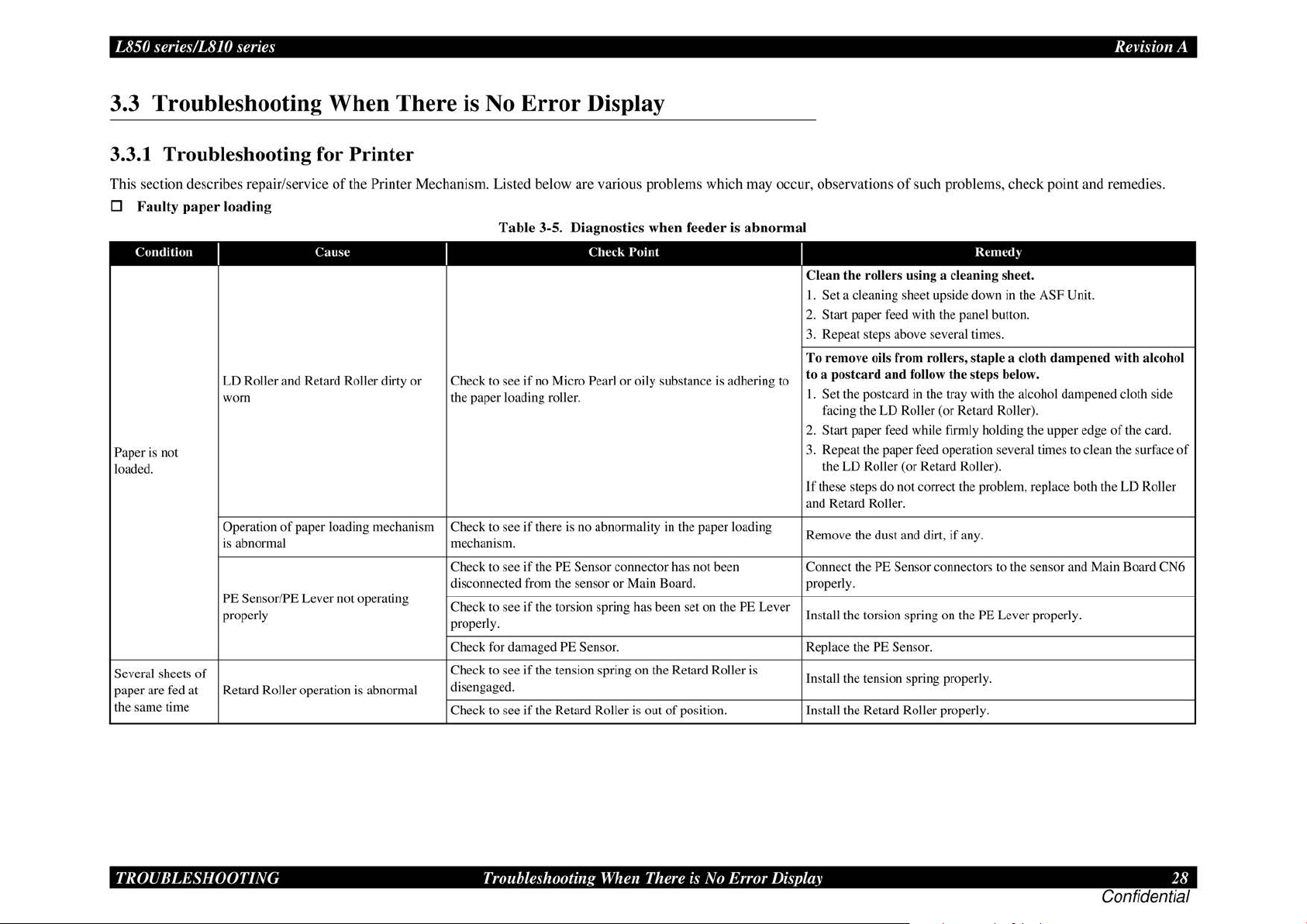
3.3 Troubleshooting When There is No Error Display
3.3
.1
Troubleshooting for Printer
This section describes repair/service
D
Fa
ulty
paper
loading
Condition
Paper is not
loaded.
Several
sheets
paper are
the same time
fed
I
LD Roller and Retard Roller dirty or Check to see
worn the paper loading roller.
Operation
is abnormal mechanism.
PE Sensor/PE Lever not operating
properly
of
at Retard Roller operation is abnorma.l
Cause
of
paper loading mechanism Check to see
of
the Printer Mechanism. Listed below are various problems which may occur, observations
Tab
le 3-5. Diagnostics when feeder is abnormal
Check
I
if
no Micro Pearl or oily substance is adhering to
Point
I
Clean the
I.
Set
a cleaning sheet upside down
2. Start paper feed with the panel button.
3. Repeat steps above
To
remove oils from roller
ostcard
to a p
I.
Set the postcard
facing the LD Roller (or Retard Roller).
Start paper feed while firmly holding the upper edge
2.
3. Repeat the paper
the LD Roller (or Retard Roller).
If these steps do not correct the problem, replace both the
and Retard Roller.
if
there is no abnormality
Check to see if the PE
disconnected
Check to see
properly.
Check
Check to see
di
se
ngaged.
Check to see if the Retard Roller is
fr
if
fo
r damaged PE Sensor. Replace the PE Sensor.
if
Sensor connector has not been Connect the PE Sensor connectors to the sensor and Main Board CN6
om the sensor
the torsion spring
the tension spring on the Retard Roller is
or
in
the paper loading
Main Board. properly.
has
been set on the PE Lever
out
of
position. Install the Retard Roller properly.
Remove the dust and
ll
the torsion spring on the PE Lever properly.
Insta
Install the tension spring properly.
of
such problems, check point and remedies.
roller
s using a cleaning sheet.
se
veral times .
s, sta
and
follow
the
in
the tray with the alcohol dampened cloth side
feed
operation several times to clean the surface
di1t, if any.
Rcmed~
in
ple a clo
ste
ps below.
the ASF Unit.
th dampened
with
of
the card.
LD
alcohol
of
Roller
TROUBLESHOOTING
Troubleshooting
When
There is No Error Display
28
Confidential
Page 29
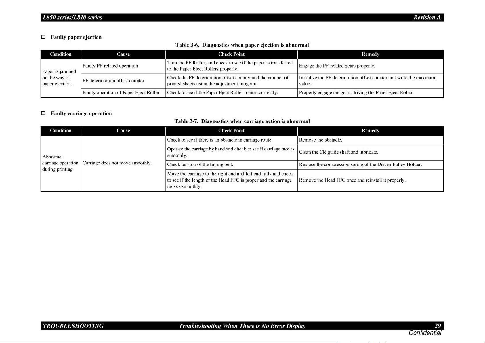
L850 series/LS
easyfixs.blogspot.com
D
Fa
ulty pap
Condition
Paper
is
jammed
on the way
paper ejection. printed sheets using the adjustment program. value.
JO
series Revision A
er
ejection
Faulty PF-related operation
of
PF deterioration offset counter
Faulty operation
Tab
Cause
Turn the
to the
Check the
of
Paper Eject Roller Check to see
le 3-6. Di agnostics when
Check
PF Roller, and check to
Paper Eject Rollers properly.
PF deterioration offset counter and the number
if
the Paper Eject Roller rotates correctly. Properly engage the gears driving the Paper Eject Roller.
paper
ejection is abnormal
Point Rcmed)
see
if
the paper is transferred
Engage the
of
Initialize the PF deterioration offset counter and write the maximum
PF-related gears properly.
D Faulty
Abnormal
carriage operation Carriage does not move smoot
during printing
carr
Condition
iage operation
I
Cause
Table 3-7. Diagnostics when carriage ac tion is
Check
I
Check to see
Operate the carriage by hand and check to
smoothly.
hl
y.
Check tension
Move the carriage to the right
to see
moves smoothly.
if
the length
if
there is an obstacle in carriage route. Remove the obstacle.
of
the timing belt. Replace the compression spring
of
the Head FFC is proper and the carriage Remove the Head FFC once and reinstall it properly.
Point
see
if carriage moves
end
and left end fully and check
abnormal
I
Clean the
CR
guide shaft and lubricate.
Re
med)
of
the Driven Pulley Holder.
TROUBLESHOOTING
Troubleshooting
When
There is No Error Display
29
Confidential
Page 30
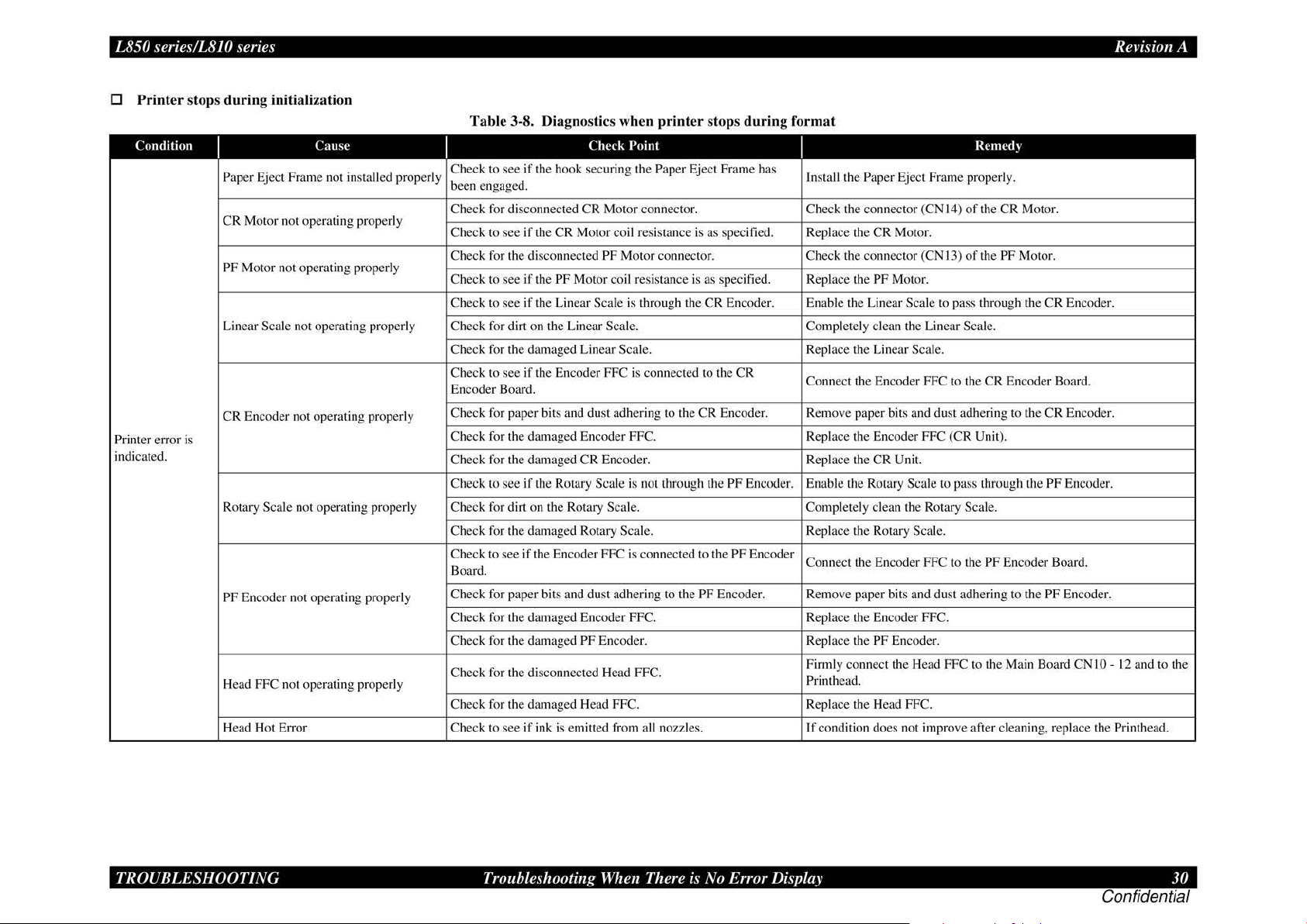
L850 series/LS
easyfixs.blogspot.com
D
Printer stops during
Condition
Printer error is
indicated.
JO
series Revision A
initializat
Paper Eject Frame not installed properly
CR
Motor not operating properly
PF Motor not operating properly
Linear Scale not operating properly Check for dirt on the Linear Scale. Completely clean the Linear Scale.
CR
Encoder not operating properly
Rotary Scale not operating properly Check for dirt on the Rotary Scale. Completely clean the Rotary Scale.
PF Encoder not operating properly
Head FFC not operating properly
Head Hot Error Check to see
ion
Cause
Tab
le 3-8. Diagnostics when
Check
Check to see
been engaged.
Check for disconnected
Check to see
Check for the disconnected
Check to see if the
Check to see
Check for the damaged Linear Scale. Replace the Linear Scale.
Check to see
Encoder Board.
Check for paper bits and dust adhering to the CR Encoder. Remove paper bits and dust adhering to the CR Encoder.
Check for the damaged Encoder
Check for the damaged CR Encoder.
Check
Check for the damaged Rotary Scale. Replace the Rotary Scale.
Check to see
Board.
Check for paper bits and dust adhering to the
Check for the damaged Encoder FFC. Replace the Encoder FFC.
Check for the damaged
Check for the disconnected Head FFC.
Check for the damaged Head FFC. Replace the Head FFC.
if
the hook securing the Paper Eject Frame has
CR
Motor connector. Check the connector (CN 14)
if
the
CR
Motor coil resistance is as specified. Replace the CR Motor.
PF Motor connector. Check the connector (CN 13)
PF Motor coil resistance is as specified. Replace the PF Motor.
if
the Lin
ear
Scale is through the
if
the Encoder FFC is connected to the
to see
if
the Rotary Scale is not through the PF Encoder. Enable the Rotary Scale to pass through the PF Encoder.
if
the Encoder FFC is connected to the PF Encoder
PF Encoder. Replace the PF Encoder.
if
ink is emitted from all nozzles.
printer
Point
FFC. Replace the Encoder FFC (
stops
during
CR
Encoder. Enable the Linear Scale to pass through the CR Encode
CR
PF Encoder. Remove paper bits and dust adhering to the PF Encoder.
format
Insta
ll
the Paper Eject Frame properl
Connect the Encoder FFC to the
ep
lace the
CR
R
Connect the Encoder FFC to the
Firmly connect the Head FFC to the Main Board
Printhead.
If
condition does not improve after cleaning, replace the Printhead.
Unit.
Rcmed~
y.
of
the
CR
of
the PF Motor.
CR
Encoder Board.
CR
Unit).
PF Encoder Board.
Motor.
CN
I 0 - 12 and to the
r.
TROUBLESHOOTING
Troubleshooting
When
There is No Error Display
30
Confidential
Page 31
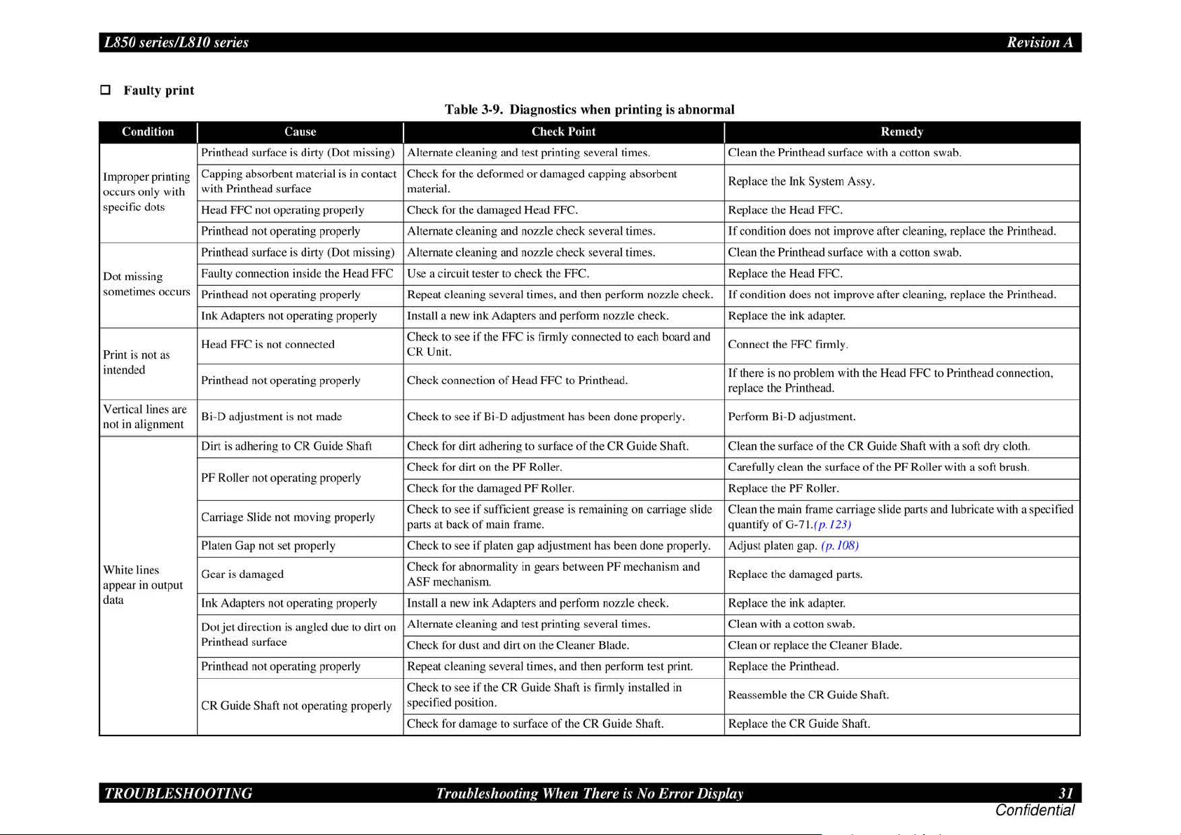
L850 series/L8JO series
easyfixs.blogspot.com
Rei·isio11
A
0 Faulty
Condition
Improper printing
occurs only with
specific dots
Dot mi
so
metimes occurs
Print is n
intended
Vertical lines
ot
in ali
n
White lin
appear
data
ss
ing
ot
gnment
es
in
output
print
as
are
Tab
le 3-9. Diagnostics when printing is
l'ausc
Printhead surface is dirty (Dot missing) Alternate cleaning and test printing several times. Clean the Printhead surface with a
Capping absorbent material is in contact Check for the deformed
with Printhead surfa
FFC
Head
Printhead not operating properly Alternate cleaning and nozzle
Printhead
Faulty connection
Printhead not operating properly Repeat cleaning
Ink Adapters not operating properly Install a new ink Adapters and perform no
ea
H
Printhead not operating properly Check connection of Head FFC to Printhead.
Bi-D adjustment is not made Check to see
Dirt is adhering to CR Guide
PF
Carriage
Platen
Gear is damaged
Ink Adapters not operating properly Install a new
Dot
Printhead surface
Printhead not operati.ng properly Repeat cleaning several times, and then perform Lest print. Replace the Printhead.
CR
not operating properly Check for the damaged Head FFC. Replace the Head FFC.
surfa
d FFC is not connected
Roll
er
not operating properly
Slide not moving properly
Gap
jet
direction is angled
Gu ide Shaft not operating properly
ce
ce
is dirty (Dot miss
in
side the Head
Shaft Check for dirt adhering to surface
not
set properly Ch
due
to dirt on
material.
ing) Alternate cleaning and nozzle check several times. Clean the Printhead surface with a
FFC Use
a circuit tester to check the FFC. Replace the Head FFC.
Check to see
CR
Unit.
Check for dirt
Check for the dama
Check to see
parts at back
eck
Check for abnormality
ASF
Alternate cleaning and test printing several rimes. Clean with a
Check for dust and dirt on the Cleaner Blad e. Clean
Check to
specified position.
Check for damage
if
the FFC is firmly connected to each board and
if
Bi-D adjustment has been done properly. Perform Bi-D adjustment.
on
if
sufficient grease is remaining
of
main frame. quantify
to see
if
platen gap adjustment has been done properly. Adjust platen gap.
mechanism.
ink
see
if lhe CR Guide ShaJt is lirmly installed in
Check
Point
or
damaged
seve
ral times, and then perform nozzle check.
the
PF
Roller.
ged PF
Rolle
in
gears between
Adapters and perform nozzle check. Replace the ink adapter.
to surface
capping absorbent
check several times.
zz
le
of
the CR Guide Shaft. Clean the surface
r.
on
PF mec
of
the
CR
Guide
Shaft. Replace the
abnorma
check. Replace the ink adapter.
carriage slide Clean the main frame carriage slide parts and lubricate with a specified
hanism and
l
I
Replace the Ink
If
condition does
If
condition does not improve after cleaning, replace the Printhead.
Connect the
If
there is no problem with the Head
replace the Printhead.
Carefully clean the surfac e
Replace the
Replace the damaged
or
Reassemble the CR Gu
System Assy.
not improve after cleaning, replace the Printhead.
FFC
firmly.
of
the
PF
Roller.
ofG-71.(p.
replace the Cleaner Blade.
(p. 108)
cotton
CR
Guide Shaft.
!23
parts.
swa
Rcmccl~
CR
Guide Shaft with a soft
of
the PF Roller with a so
)
b.
id
e Shaft.
conon
swa
b.
couon swab.
FFC
to Printhead connection,
dry cloth.
ft
brush.
TROUBLESHOOTING
Troubleshooting When There is No Error Display 31
Confidential
Page 32

L850 series/LS
easyfixs.blogspot.com
JO
series Revision A
3.3.2 Power Supply Related Troubleshooting
If
the printer
Defective power cord Connect the normal power cord. Replace the power cord.
Abnormal
Faulty connection
Fuse blown Check the fuse
Ab
normal output voltage
Board
does
not operate
Cause
AC
power voltage Check the
of
the connector
at
of
Power Supply
all
(LE
D does not light up)
I
Check the connection between the
- Main Board (CN3).
Check the output voltage
even
with the power turned ON, refer to the following table and perform troubleshooting.
Table 3-10. Power S
Check
Point
AC
power voltage. Supply the normal power.
Power Supply Board
(F
I)
on
the Power Supply Board. Replace the Power Supply Board with a new one.
of
the Power Supply Board.
uppl
y Related Troubleshooting
I
Correct the connection.
When the output voltage is normal: Replace the Main Board with a new one.
When the output voltage is abnormal: Replace the
Remed)
Power Supply Board with a new one.
TROUBLESHOOTING
Troubleshooting
When
There is No Error Display 32
Confidential
Page 33

L850 series/LS
easyfixs.blogspot.com
JO
series Revision A
3.3.3 Ink Supply Related Troubleshooting
D
Printing
Carriage moves
correctly but printing
is not normal. new one.
D
Wa
Ink is not flowing from
Printhead to Cap
from Cap to Ink
is
Condition
ste
ink
Condition
not
carried out
is
not
or
Tube
correctly
Tabl
e 3-11. Diagnostics when printing is e
I
FFC not connected Check the FFC connection between each CSIC Board -
properly Main Board.
Cleaner Blade not
operating properly
FFC internal disconnection Check each FFC with a circuit t
Faulty
Ink leakage
with ink Check that Ink Tubes are not crumpled. Relea
disc
har
I
Pump tube collapsed Visually check the tube. Replace the Ink System Assy
Cap is dirty
Tube is disconnected from Visually check for disconnection
Cap
Cap does not slide up Check for installation
properly assembl
Tube
Ink Tray Assy - l/S Assy
collapsed
Cause
Printhead Alternate cleaning and t
or
clogging
ged
prop
erly
Cause
or
damaged.
bottom bottom.
between the Waste
I
Check for debris adhering to the Cleaner Blade. Clean
Check to see
Check that Ink Tube connections are complete. Reassemble Ink
Tab
le 3-12.
Troub
I
Check for foreign object adhering to the Cap
damaged Cap. replace the Ink System
y.
Check the tube connection
Ink Tray Assy and the tube route under
Check
Point
ester.
est
printing several times.
if
there is ink leakage from the Printhead.
leshooting for Faulty Ink Supply
Check
Point
or
of
the
tub
e from
of
compression spring on the tube
on
the bottom
the
of
tray.
the Waste
I
Connect
Repla
When the condition is not improved even after clean
Install the ink Adapters properly.
If
this does not improve the con
or
Faulty Waste
I
Remove foreign object from the Cap with a cotton swab.
Cap
Connect the tube properly.
R
ep
Connect the tube
rratic
Remed)
the
FFC firmly.
or
replace the Cleaner Blade.
ce
the FFC.
dit
ion, replace the ink Adapters and the Printhead.
se
crumpled Ink Tube.
Tube
s and compete their connections.
Ink Disc
lace the Ink System Assy with a new one.
of
harge
Re
med)
As
sy.
the Waste Ink Tray Assy proper ly, and route the tube properl
in
g, replace the Printhead with a
If
the Cap is damaged,
y.
TROUBLESHOOTING
Troubleshooting
When
There is No Error Display 33
Confidential
Page 34

L850 series/LS
easyfixs.blogspot.com
JO
series Revision A
3.3.4
l/F
Related Troubleshooting
This section describes the troubleshooting for the USB I/F and Memory Card Slot.
D USB
Host PC does not
support Windows
XP essentiall
Print
not installed
correctly.
Defective USB Operation is normal
cable replaced?
Poor contact foreign matters in the
Defective m
board damaged.
Cause
er
driver is
IIF
y.
ai
error
Table 3-13. USB
I
On
Windows, open "My computer"
~"Property"~
"Universal serial bus controller" is
effective?
On Wi ndows, open "My computer"
~"Property"~"Device
Printer driver is installed
devices" by mistake?
Check to see if there is no adhesion
connector.
n Ch
eck
Check
"Device manager". Remove the USB driver , and
ifUSB
to see if the main board is not
IIF
Point
manager".
in
"Other
cable
is
USB interface
Error
I
in
stall it again.
Delete the driver and install it
again according to operation
manua
Replace the USB cable.
of
Remove the foreign matters,
and clean the contact.
Replace the main board.
Remed~
l.
D Troubleshooting for Memory
Table 3-14.
Cause
Driver has not Check to see if a memory card
been installed is recognized
correctly. mode.
Data has been Data on card may be destroyed
destroyed. due to sta
A memory card
other than those
specified is used.
Memory card is Check to see
faulty. card can be recognized.
Poor contact. are not adhering to memory
Firmware has
abnormality.
Electric noise, etc.
has been
generated.
Defective main Check to see if the main board
board is not damaged.
I
Check the card to see if it is one
of
Check to see if foreign matters
card or slot.
Check to see if the FFC is
connected correctly and the After the
Ferrite Core is positioned in abnormality, replace the main board.
place inside the printer.
Check
ti
the spec
Card
Slot
Trou
bleshooting for Memory
Point
in
the single Assy
c electricity. PC.
ifi
ed cards.
if
another Memory
---
Card
I
Temporarily rem
install it agai
Check to
If
not, format the card.
Use a specified memory card.
Use a new memory card.
Remove the
the contact.
Update firmware.
Replace the main board.
Rcmcd~
ove
the driver, and then
n.
see
if
card data is read by a
fo
reign matters, and clean
conftrmation,
if
they have no
TROUBLESHOOTING
Troubleshooting
When
There is No Error Display
34
Confidential
Page 35

L850 series/L8JO series
easyfixs.blogspot.com
Rei·isio11
A
3.3.5 Troubleshooting for
Scanner
This section describes repair/service for the Scanner mechanism.
id
entify the trouble at the Assy level based on the observation.
first
in
According to tbe observatioo as described
checking by referring
D Scanner
Errors
to
the appropriate table.
at
User Level
Table 3-15. Scanner
Error
Scanner
Co
mmand error Undefined command is detected.
Scanner open Scanner cover is open. Clo
0 Observation
I
• D
efec
error
• Defective scanner motor
• The scanner carriage is
interfe ring with any
of
Trouble and Reference for Remedy
Tab
le 3-16. Observation
Ohscnation
Cause
tive CIS unit
ot
of
Table 3-16, perform the oecessa
Errors
at
User Level
I
• Repla
ce
the scanner
• Remove the obstacl
her part.
correc
When
status is
Turn the power
on again.
se
Troub
le and Reference for Remedy
Description
t command is received, error
cancelled.
off
the
cover.
of
Trouhle
I
Even with power turn
machine does not operate. initializatio
"Fatal error" occwTed.
Indication error occurs and it is not
cleared even after power is turned
nc
e and then turned
o
ct
ure is n
mmuni
ot rea
cat
Pi
"Co
Indication error occurs and when
communication with the ho
again, "Communication error" recur
ed
on
d clearl
ion error".
on, the
again.
y.
st
is tri
The mac
CR unit does not operate. Table
CR unit operat
indicated.
off
The
Pic
USB interfa
ed
s.
hine does not operate for
n.
es
but error is
LED does not light up. Table 3-20
tur
e is n
ot rea
d clearl
y.
ce error Table 3- 13
In
troubleshooting,
ry
Re
med~
CR
Unit.
e.
once and then turn it
I Reference for
Rcmed~
Table
Table
Table 3-21
3- 17
3- 18
3- 19
D Scanner does n
Causl'
Connector is
disconnected.
D
Carriage
ot
Tab
le 3-17. Scanner does not operate for initialization
unit does not operate
Tab
Cause
Connector on the Main
Board is disconnected
Faulty
ca
rri
age moving
mechanism
CR
Faulty
Defec
motor
ti
ve main board --·-
oper
ate
for initialization
Check
I
Check each connector for
dis
connec
co
nnector disconnected?
Point
tion. Is there any
I Yes/l\o I
Yes
No
le 3-18. Carriage unit does not operate
I
Chcl·k Point
0 Is any
0 Grea
I.
2.
D Disconnect the
of
the connectors
(
CNl7, 19 and
Main
Bo
ard disconnected?
se
is applied
properly?
Does CR motor operate
when power is turned
with upper case
removed?
Do
es CR unit move with
CR
mot0r removed?
(CN
17) of
the
from the Main B
ec
k continuity between
ch
pin I and pin 2
motor side, us
tester.
20) on the
of
Scanner mechanism, replace the
connector
CR
Motor
oa
rd, and
on
the
in
g a circuit
I Ycs/l\o I
Yes Connect the connector.
No
ON
No
No Replace the
--
Rl·mcd~
Co
nnect the disconnected
connector.
Repla
ce
the main board.
Re
med~
Apply grease at designat
point
Check the
relevant parts
and
Repla
car
ria
ge
or
reinstall them.
CR
motor.
ce
the main board.
moving
remove
ed
TROUBLESHOOTING
Troubleshooting When There is No Error Display 35
Confidential
Page 36

L850 series/LS
easyfixs.blogspot.com
D C
arriage
JO
series Revision A
operates
but error
indicat
ed
Table 3-19. Carriage operates
Cause
Upper case
removed. removed?
Defecti ve main board
of
scanner is Upper
D LED does not lig
Cause
Connector
Board is disconnected board is disconnected? CN19 on the main board.
Defec
Defective main board
D
on the Main Connector CN 19 on main
ti
ve CIS Unit
Picture cannot
I
ht
I
Does the lamp light up when
be
read clea
Tab
Cause
Soiled docum ent table free from dirt and wiping
Defective CIS
Defective main board
Unit
I
Is the document table (glass)
Chl·ck
Point
case
of
scanner is
---
up
Table 3-2
the CIS Unit is replaced?
0.
Check
LE
---
D does
Point
rly
le 3-2
1.
Picture
Check
Point
mark?
---
---
cannot
but
error
indicated
I
Yes/l\o
I
Y
es Install the upper case.
--- Repla
not
lig
ht
up
I
Ycs/l\o
I
Connect the connect
Y
es
Y
es
Repla
--- Replace the main
be read clearly
I
Yes/l\o
I
Clean the document table.
No
--- Repla
Replace the main board
---
Remed~
ce
the main board
Re
med~
ce
the CIS Unit.
Remed~
ce
the CIS Uni
or
board
t.
TROUBLESHOOTING
Troubleshooting
When
There is No Error Display
36
Confidential
Page 37

easyfixs.blogspot.com
DISASSEMBLY AND ASSEMBLY
Confidential
Page 38

L850 series/L8JO series Revision A
easyfixs.blogspot.com
4.1 Overview
Description in this c
But some
below
•
js
section describes proce
Th
product.
Unless otherwi
in
revers
4.1
.1 Pre
See the precautions given under the heading
fo
llowing column when disassembl ing or assembling the produc
observed, that could result
"Warning". Precautions for any disassembly or assembly procedures are d
un
der the heading "CAUTION". Chips for disassembling procedures are described
th
under
reversed proce
"REASSEMBLY". Any adjustmen
described under
remove any units or par
diagrams
starting.
se
g the disassembly procedure.
cautions
e heading "CHECK POINT".
dure of
th
in
the appendix. Read precautions described in the next section before
•
a
•
•
of
it
fir
st and follow the ins
specified, disassembled
in in
the disassembling, the procedure is described under the heading
e heading "A DJUSTM
ts
that are not described in this chapter, refer to the exploded
Di
sconnect the powe r cabl e before disasse mbling or assembling
th
e printe
Always wear gloves
injury fr
pr
otect sensitive micro
To
arge equipm
disch
in
access
g internal c
hapt
er is
appli
ed
to
L850 series/L810 series.
isn't appli ed to L810 series. For L810 series, see
tru
ction s.
dur
es for disassembling the ma
uni
ts or components can be reassembled by
"WA
RNING" a
jury or loss
ts
r.
om sha rp m
of life are described under the heading
If
the assembling proce
required after disassem
ENT
REQUIRED". When yo u have to
for
disasse
eta
l edges.
pro
ent, such as
ompon
ents.
mbl
cessors a
anti-sta
in
components
nd
"CAUTION" in the
t.
Things, if n
dur
e is different fro m the
blfo
g the units are
y a nd reas
nd
circuitr
tic wrist straps
sem
bly to avoid
y, use s
of the
escribed
, when
ot stri
tati
ctly
c
CAUTION
I
l
•
J •
•
•
•
•
en using c
cleaning duri
produ
cts c
Ma
ke the specified a
series/L810 series.
Use the special package for trans
Pri
or to disassembly a
such as me
Wh
en removing or insta
that
no coated s
ompr
essed a
ir
products; such as a
ng
repa
ir a
nd
maintenance, the use
ont
aining flammabl e gas is prohibited .
mory car
urfa
djustment
nd
ds.
ce is scrat
s when y
reasse
lling exte
ched a
ou
por
tat
ion .
mbl
y, remove the accessories,
rior
parts, t
nd
no coating is peeled
ir duster, for
of
such
disassemble th e L850
ake great
care
off
Wh
4.1.2 Tools
Use only specified tools to avoid damaging the L850 series/L8 IO series.
Ta
ble 4-1. Tool
'.\lame Tool
Pbjllips precisioo screwdriver 1
Phillips precision screwdriver 1
Tweezers
Note : All
of
the too ls listed above are commercially available. EPSON provides lhe tools
listed with
EPSON tool code.
s
l'ock
080530
080532
1
08056
1
4.1.3 Preparation before Disassembly
Make the followin
D When the M
D When the CR
th
er than the home pos
o
a
nd
turning it OFF timely. (See 4.
D As soon as the repaired product has been returned to the user, there may be a case
a
mruntenance ca
A vo
id
reg
ularly replaced parts before disassembly.
expired, communi
re
pl
ace also the relevant service parts with new ones.
g preparations before disassembling the L850 series/L8 I 0 series:
ai
n Boa
rd
is to be replaced, make a copy
Unit is to be moved out of i
iti
ll
such a case,
occw·s because
if
possible, as foll
ca
te with the user to that effect.
ts
home position, locate it at a position
on before starting disassembly by turning the power ON
1.5
How
to
Unlock the Carriage
of
the expiration of the life
ows: Check the maintenance counter for
If
of the EEPROM data.
of
the life
of
any part is foun
If
th
e user's consent is obtained,
(p
.
39
a servi
))
ce part.
d almost
.
DISASSEMBLY
AND
ASSEMBLY
Overview
38
Confidential
Page 39

L850
easyfixs.blogspot.com
series/L8JO series Revision A
4.1.4 Making a Special Tool for CSIC Board
The CSIC board (refer to p.
method for making the tool is described below.
1. Prepare a handle part
Figure 4-1. Making Special Tool for CSIC Board (1)
2.
Bend the metal wire as shown below.
of
74
) can
a clip,
be
easily removed by using a special tool.
or
a similar metal wire piece.
The
4.1
.5
How to Unlock the
0
Some
of
the disassembling operations require unlocking the carriage. In those
cases, carry out any
the carriage to other than its home position.
CAUTION
Be
mu
of
the following operations
extremely
st
be taken to avoid
caref
ul n
I
•
•
Tum
the pow
Unit becomes unlocked and moves away from the home po
• Until the
printer in the direction
er
ca1Tiage
off
forcibly by disconnecting the power cable when the CR
is unlocked, turn the EJ Roll
of the arrow as shown in Fig. 4-3.
Carriage
to
unlock the carriage and move
ot
to damage the EJ Roller gear.
injury
from sh
arp
metal edges.
er
gear on the left side
sit
ion.
Extra
of
care
the
DISASSEMBLY
Figure 4-2.
AND
Making
ASSEMBLY
Special Tool for CSIC Board (2)
Special Tool
Overview
Figure 4-3. How to Unlock the Carriag
-
e
39
Confidential
Page 40

L850 series/L8JO series Revision A
easyfixs.blogspot.com
4.1.6 Checks
4.1.6.1 Factors which Affect the
HOW
TO
PLACE
REASSEMBLING
The
Ink
Supply
The
ink
in the ink tanks is vented to the atmosphere through this hole to stab
supply to the Printhead.
ea
k from the air release hole.
l
ventilation to the atmosphere
affected adversely.
In order to prevent this from happening, make sure to place the
ow
as sh
n below after removing it.
Tank
and
Precautions before Disassembling
Pri
nt Quality
THE
INK TANK ASSY WHEN DISASSEMBLING/
Assy
of
this printer has an air release hole on the upper part.
If
the Ink Supply
If
the
ca
nnot be done properly and the print quality may be
Tank
Assy is tilted, the ink in the tanks may
air
release hole is sealed
up
with the leaked ink,
Lnk
Supply
Tank
4.1.6.2 Factors which Affe
Ink
Leakage during Operation
lnk
may spill when removing the following parts from .
sect
This
ink
THE
ili
ze
ink
Assy
ion describes the parts that may cause ink spill
sp
ill
when removing the parts.
PARTS
- Joint
[
-
,.
THAT
MAY CAUSE INK
Parts
~
lnkSupply
Tank
Assy
Ink Supply
Tank Tube Assy
(w/Valve Assy)
Adapter Removing the Ink Supply
ct the Safety of Service Personnel such as
I
Removing the
/ Ink Supply
D Remov
Tank
D Remov
Tank
Tank Assy
the Adapter
and the means
SPILL
WHEN REMOVING
\\hen
ink
ma~
spill
ink
Supply
Tank Tube
Tube
Assy from the Joint
in
g the tubes
Tube Assy from the Joint
in
g the tub es
Tube
Assy from the Ink Supply
of
of
Tube
the
the
Assy
lnk
Supply
Lnk
Supply
Assy from
to
minimize the
[ Lorntion
A,B
A
c
e
Tnk
-
Supply D Removing the
Tube
Assy
I
Lnk
Removing the Ink Supply
D
from the Adapter
Supply Tube Assy
Tnk
Supply Tank Tube
from
the Joint
Tub
e Assy
Assy
A
,C
DISASSEMBLY
Figure 4-4. How to Place
AND
ASSEMBLY
Do
not plac!' the Ink Supply
lhe
air release holes down or to one of lhe
sides.
Oth
Ta
le
er wise. the ink in the Ink Suppl y
nk
Assy muy come up to the holes and may
ak
or the print failure may oc
the
Ink
Tank
Assy
Tank
cur
Ass~
.
·
wi
th
Overview
Figure 4-5. Location
40
Confidential
Page 41

L850
easyfixs.blogspot.com
series/L8JO series Revision A
•
Di
MEANS DO
TO
MINIMJZE THE INK
SPILL
Even observing the points described in this section, ink may spill in
the following situations. Therefore, be careful not
the inside
container
•
of the
print
er
or
its s
urroundin
to receive the leaked ink, or the like.
When removing the
Ink Supply Ta
Assy), some ink will spill from both e
gs by preparing
nk Tub
nds of
to
contamina
the
e Assy (w/Valve
the
tube
even
te
the
scharging preparation
1.
Remove the scr
2. Release the hook
Dowel .
3. Release the Ink Supply
the Middle Housing.
ew
(x 5)
of the Guide
1!1!1!!11111111!11!!!11~
of
the Guide
Tube
from rib, and release the Guide
Tub
e 1st and the Tube Hold
Tube
Sub , Release the Guide Tube from
Valve Lever is closed.
When removing the
•
tube
will spill.
Ink
Suppl y Tube Assy, all the ink in the
Tube
er
lst
(x 2) .
from
Before disassembling, confirm that the printer is
DISCHARGING INK
Discharg i.ng ink is reco mm ended only when disconnecting the Ink Supply
Assy from the Ink Supply Tank. Before performing the above disconnection, discharge
ink from t
he
Ink Supply Tank as follows.
Necessary tools
•
Containers (x
•
• Injector (with a tip
• Clips (x
• Cotton swab (x 6)
2)
FROM
6)
THE INK SUPPLY TANK
for each di scharged ink
of
<j>3.2
mm)
• When disconnecting the
Tube from the
Joint,
a con tainer to receive the leaking ink to
from getting co
•
Prior
and
then disc
to
the
following
ntaminated
har
ge ink according to the procedure.
in the following condition.
Tank
Tube
Ink
Supp
ly
Tube/Ink
Supp
ly
Tank
ink may leak from the ink tube. Prepare
prevent
by
the leaked ink.
ste
ps, connect the injector with t
the
produc
he
tube
t
,
Figure 4-6. Discharging
4. Move the Carriage to right side .
5. Release the Joint from the rib
of
Guide
prepa
ration (1)
Tube I st.
DISASSEMBLY
AND
ASSEMBLY
Figure 4-7. Disc
harging
preparation
(2)
Overview 41
Confidential
Page 42

L850
easyfixs.blogspot.com
series/L8JO series Revision A
• Discharging procedure
L.
Release the Ink Supply Ta
(p.41
))
2. Place the Ink Supply Tank Assy on a place where its bottom is higher than the
of the Printhead.
top
3. To mini
Tube , pinch
4.
Prepare a container for ink to discharge, then disconnect the Ink
from the joint and put its
5.
To discharge the ink
mize
the ink leakage from the Ink Suppl y Tub e / Ink Supply Tank
th
e Ink Supply Tube I Ink Supply Tank Tube with clips
Fig
nk
Assy.(Ref
ur
e 4-8. Discharging
tip in
to the contain
in
the Ink Supply Tank Assy to the container.
er
to Disc
Ink
er for the ink.
harging prepara
(1)
tion
(x
2) .
Supply Tube
6. Move the
Supply Tank Tube .
7. The
Ink
8.
Repeat step 4 to Step 7 for a
T
ank.
clips (x2) so that only the ink to discharge can flow
in
k in the Ink Supply Tank is discharged into the container through the
Supply Tank Tub
•
It
is recommended that the
be disc
reassembling.
•
After
all the reassembling work is complete, the disch
of each co
befor e perfo
ind
icated on the film of the
sta
ke them, and make sure to refill each
mi
orr
ect tank
c
e.
ll
ink tanks to discharge a
Figure 4-10. Discharging
ink
har
ged compl
lor
rming the a
from the c
ete
ly b
efore procee
sho
uld
be refilled back to the I
djustment. Co
orresponding ink suppl
lnk Supp
ll
ink in the Ink Supply
Ink
(3)
in the
Ink Supp
din
g to disassemblin
nk Suppl
nfirm the colors
ly Tank so as not to
ink back to the
in
the Ink
ly Tank should
g/
arged ink
y T
ank
y hole.
DISASSEMBLY
AND
ur
e 4-9. Discharging Ink
Fig
ASSEMBLY
(2)
Overview
42
Confidential
Page 43

L850 series/L8JO series Revision A
easyfixs.blogspot.com
4.1.7 Protection for Transportation
Before packing the printer for returning it to the user, secure it
with
st
rong tape to avoid damaging the printer
make s
ur
e to check the points as foUows.
D Securing each parts
Secure the following parts with strong tape.
• Securing the Carriage Unit
Pr
epare a piece
I.
Co
Put Pad Carriage on the Carriage.
2.
3. Attach the unfolded end
left side
Pull the tape towa
4.
shapes
of
strong tape (lengt
nfirm that the Carriage Unit is locked in the h
of
the Carriage.
rd
the right side
of
the housing as shown in Fig. 4- 12 to secure the Carria
h:
of
strong tape (fold the other end back 5 mm) on the
or
ink leakage during transport, and
140
± 2
mm
, width:
ome posit
of
the housing and attach it tightly along the
:;a..--i
Carriage pushed to home
position
at the specified points
22
mm).
ion.
ge
Unit.
Figure 4-12. Sec
uring the Car
riage Unit
DISASSEMBLY
Figure 4-11. Sec
AND
ASSEMBLY
uring the Ca
rri
age Unit
Overview
43
Confidential
Page 44

L850 series/L8JO series Revision A
easyfixs.blogspot.com
• Secw·ing the
Prepare two pieces
Install the Ink Supply
I.
2. Attach strong tape along the shapes
Secure the Housing Middle, Ink Supply Tank Assy, and T
st
rong tape (x2).
• Securing the Ink
l:nk
Tank
Top
of
strong tape (length: 90 ± 2 mm, width:
Tank
Assy to the printer.
of
Figure 4-13. Securing the
Tank
Bottom
Ink
the Tank Assy as shown
Supply
Tank
22
Top
mm).
op
Cover with
in
Fig. 4-13 to
• Securing the Stacker Cover
Prepare two pieces
I.
Attach strong tape along the shapes
Secure the Stacker Cover with strong tape (x2).
of
strong tape (length: 60 ± 2 mm, width:
of
the
22
mm).
Tank
Assy as shown in Fig. 4-15 to
Prepare a piece
I. Attach
DISASSEMBLY
of
stro
ng
tape (length:
st
rong tape along the shapes
Secure the Housing Middle and
Figure
4-14. Sec
AND
uring the Ink
ASSEMBLY
180
± 2
mm
, width: 22 mm).
of
the
Tank
Assy as shown in Fig. 4-.14 to
In
k Supply Tank Assy with strong tape (x2).
Supply
Tank
Bottom
Overview
Figure
4-15. Securing the
Stacker
Cover
44
Confidential
Page 45

L850 series/L8JO series Revision A
easyfixs.blogspot.com
4.1.8 Packing methods
To
avoid the troub le, such as ink leaks. Products need to be packed following
to the procedure mentioned below.
"
Highland"
the
center
In
• :
•
Amount
of
in Ink Tank
Porous
2
Pad
case
"Lowland" is
If
it is
apply a method
ink
place
F
Attach Not Attach Attach on the Ventilation Hole.
where
is
over
of
the
the
condition
Tab
ull
means
the
1,
OOOm
customer
applied.
same
le 4-2. Pe
N
ot
Fu
that
applied
altitude
asl .
who
exce
pt
as
before.
ttern
of
Full;
ll
Not
to
the
customer
difference
is in le
two cases
packing
Fill
ink up upper
Fu
ll; An original amount
with
ss
than
mentioned
who
service
lOOOm asl ,
limit
line.
of
is in
above,
ink is kept.
• All the caps
Assy are securely closed.
•
The
opened ink
included
of
in
the box.
the Ink Supply Tank
bon
le is not
• The hooks (x2)
Tank Assy are securely engaged
the Decoration Plate Rig
with
of
the Ink Supply
ht.
• •
DISASSEMBLY
Figur
e 4-16. Attaching the Porous
Information
Size : H 34mm x W 188mm x Smm
ASP
AND
of
Porous
Code : 155606000
ASSEMBLY
Pad
is
as
follows
Pad
Overview
45
Confidential
Page 46

L850 series/L8JO series Revision A
easyfixs.blogspot.com
•
Imp
ortant
1.
Attach the Porous Pad notin g that Porous Pad covers all Ventilation holes
of
Ink Tank.(Fig. 4-17)
2.
The
height positions
Ink Tank.(Fig. 4-18)
3.
If
the
risk that
the
tube.
points when attaching the Porous
of
Porous Pad is almost the same as the air chamber in
Porous
Pad
is
the
tube
(Fig. 4
attached
becomes
-1
9)
more
kink
up
because
remarkly
the
Porous
than
Pad
the
Pad
air
chamber , there
pushes
the
curved
is
pa11
the
of
•
Important
I.
Set
the tube to become loose curved as much as possible(Let the tube loose
on the right hand).
If
curve
of
points when hanging the
the tube is sharp,
it
might make the tube kink.(Fig. 4-19)
Ink Tank to
product
's
main body
DISASSEMBLY
Figure 4-17. Attaching the
A
ir
Chamber
Figure 4-18.
AND
The
heig
ASSEMBLY
ht
positions
Porous Pad
of
Porous
(l )
Pad
(2)
•
Overview
Figure 4-19. Cur
• Key point when
pl
Never
ace the
ink may leak
or
print
the
ve
of
transporting
er
upright
print
er does
the tube
produ
cts
after
filling ink, otherwise
not
print
correctly.
46
Confidential
Page 47

L850 series/L8JO series Revision A
easyfixs.blogspot.com
4.1.9 Disassembly
and
Reassembly
Procedure
The flowchart below shows step-by-step disassembly procedure for L850 seri
component.
ST
~
~
--~----=====-
r
L--r--
r--
4.2.6
L--r--.J
r
4.i
.8M ain Board Uni1 ,
L
--r--
r4.2
"}"
E
L _ Tr
r ,
4.3
.I
Ach1p
L--r--.J
'4
.3.2 I
nk
L
--r--
'4.33 tnk Supply Tank
L
~ssr..::
M/B
C
ove
(/>.
60)
MJ
Fmmc/W"'
!!l_
Ass
1er
sec1io
Supply T
section
(11.68)
ec1ion
--,
r
(1>.58)
(p.58)_
n
(p
ube
!£:.
70
iCink,
.67)
Assy,
Tube,
2_ .J
4.2.7 EMI FramelWas1e Ink
Tray
Ass
(
4.4. J
Pri nth
ead
.J
.J
4.3.1 Adapterscciion (p.67)
.J
>.58
(fl
· 74)
4.2.5 Panel Unil
4.2.6 M/B Cover
4.2
.8
Mni
(
4.3
.2 I
nk
Supply Tube Assy
section (
n Bo
.60)
.68
ard
(p
.56)
(p
.58)
Unit
4.3.3 I
nk
)
Supply Tank Tube
Ass
section ( '·
es/LS I 0 seri
70)
es. When disassembling each component, refer to the p
You need to remove the
they exist on the way to the
The
color
•·
4.3.4 Ink Supply Tank As
section (
·.
"71)
may differ from the final product.
sy
r
L
and shape
4.4.IOCR Unit
4.4.6 Trik
(fJ
-
-I-
- - - -
r
4.4.7
ASF
L
Syste
.8/)
Unit
(p.86)
~
(p.82)
parts/units shown in das
target
of the
printer
r 4.
4.T2 Up
L
--r--
r 4
:4.°
11 Paper Eje
L _
~sy(1.
4.4.13
u;;;i
-
,
.J
Fro
A!\S
age
indicated for the relevant
part
/unit.
illus
trated
in this manual
per Paver
Guides,
(p
.91) .J
ct Fram
e ,
89)
_ J
nt Paper Guide
( .92)
hed
line box
if
4.4.8
r ,
4.4.2 Linear Scale
L--r--.J
r 4.4.4
L - -0--.J
DISASSEMBLY
APG Unil
PF
EncoderiPF Scale,
4.4
.2 Linear Sc:Lle
(p
.83)
(p
. 76)
4.4.6 Ink
4.4.7
ASF
4.4.12 Upper Paper Guides
AND
ASSEMBLY
Sys1cm
( .8/ )
Unit
( .
91)
(p
(/>.
Unit
.82)
76)
4.4
.5
PF
Moior (p. 79)
4.4.9
CR
Mo
ior (
11.85)
4.4. l I Paper Eject Frame
Assy (
Flowchart 4-1. Disassembly
Overview
,.89)
Procedure
4.4.
14
Was
1e Ink Pads
( .94)
4.2.10 Power Supply A
( J.
66)
ssy
47
Confidential
Page 48

L850 series/L8JO series Revision A
easyfixs.blogspot.com
4.2 Disassembly
4.2.1
D Parts/Components need
D Removal procedure
I. Open the Paper Support Assy.
2.
Paper
Push the bushing
the dowel
with disengaging the Edge Guides.
Support
of
the Paper Support Assy, and then remove the Paper Support Assy
Figure 4-20. Removing the
of
Assy
to
be removed
of
the ASF Unit (left side)
Exterior
in
advance: None
Parts
in
the direction
Paper Support
of
the arrow to release
Assy
4.2.2 Stacker Cover
D Parts/Components need to be removed
D Removal procedure
l.
Pull the Stacker Cover forward
2. Release the dowels (x2) that secure the Stacker Cover, and remove the Stacker
Cover from the Lower Housing.
to
in
open it.
advance: None
DISASSEMBLY
When assembling
protru
sion
of
the Edge Guide on the left
dowels
of
the
Paper Supp
Figure 4-21. Installing the
AND
ASSEMBLY
the
Pap
er Supp
ort
Assy in the
ort Assy, align
end,
and engage the
order sho
Paper Support
the
hole with the
wn below.
Assy
Disassembly
of
Exterior Parts
Figure 4-22. Removing the
Stacker
Cover
48
Confidential
Page 49

L850 series/L8JO series Revision A
easyfixs.blogspot.com
•
4.2.3 Document Cover/ ASF Cover
D Parts/Components need
D Removal procedure
• Document Cover
1.
Open the Paper Support Assy
to
be removed in advance: None
ASFCover
I. Open the Paper Support Assy
2. Release the both guide pins
Unit, and remove the ASF Cover.
of
the ASF Cover fro m the holes
of
the Scanner
2. Lift the hinge part
th
and remove
e Document Cove
F
igur
e 4-23. Removing the Document Cover
of
the Document Cover slightly and release 1he hooks (x2),
r.
H
ook
Figure 4-24. Removing the ASF Cover
I
DISASSEMBLY
AND
ASSEMBLY
Disassembly
of
Exterior Parts
49
Confidential
Page 50

L850 series/L8JO series Revision A
easyfixs.blogspot.com
4.2.4
•
0 Parts/Co
Upper
Housing/Scanner Cable Cover
The
Scanner
sc
rewdriver
Housing;
Unit before removing
The
screws
L-shaped s
removing
5 (
p.51
Figure
mp
onents need to be removed
0 Removal procedure
I. Open the Scann
2. Release
arrow.
th
e hook
er Uni
Unit
cannot
for
removing
therefore
that
sec
crewdriver,
the
Scanner
).
I L-shaped screw
4-25. L-s
t.
of
the Scanner Cable Cover and remove it
be opened enough to use a general
the
screws
, this section describes removing the
the
Upper
ure
the
Upper
a s
tubby
Unit, in
dr
iver I
hap
ed
Screwdriver
in
advance: None
Housing.
Housing
driver
that
case, you
that
or
sec
ure
the
Upper
can
be removed with a
a s
imilar
tool
can
skip the step
Stubby driver
and
Stubby
in
the direction
Scanner
without
Driver
3 to
of
the
3. Close the Scanner Unit and remove the screws (x2)
Figure
4-27. Removing
the
Upper
of the hinge
Housin
g (1)
pa11
.
Scann
DISASSEMBLY
I Left insi
de
er Cable Cover
I
Figure
AND
4-26. Removing
ASSEMBLY
the
Scanner
Cable
Cover
Disassembly
of
Exterior Parts
50
Confidential
Page 51

L850 series/L8JO series Revision A
easyfixs.blogspot.com
CAUTION
When removing the Scann
to damage the
cab
les
er Uni
of
the Scanner Unit connected to the
I
•
4. Pull out the hinge
5. While k
arrow as shown in Fig. 4-28 to remove the Scanner
eep
of
the
Scanner Unit on the left side.
ing the
Scanner Unit open at 45 degrees, push it in the direction
t from the printer, be careful n
printer
of the
Unit from the right hinge.
ot
6. While holding the Scanner Unit, rem
.
Housing.
ove
the screws (x7) that secu
re
the Upper
Figure 4-29. Removing the Upper Housing (3)
7. Put
8. Pull the Panel
the
Scanner Unit on the Upper Housing.
Unit forward, and relea
P
ane
l Uni
t.
se
the hooks (x2) on
the
both sides under the
DISASSEMBLY
Figu
AND
re 4-28
. Removing the Upp
ASSEMBLY
er
Housing (2)
Disassembly
Be
careful
noc
damage cables
10
Figure 4-30. Removing the Upper Housing (4)
of
Exterior Parts 51
Confidential
Page 52

L850 series/L8JO series Revision A
easyfixs.blogspot.com
9. Lift a
nd hold
Scanner Unit
the Scanner Unit, and re
move
the Upper Housing.
If
a Mall comes off when installing the Upper Housing, align
the
grooves of the Mall
with
the
ribs
of
the
Upper
the Middle Housing.
Fig
ur
• When in
(x3) on
•
When in
sta
the
sta
e 4-32. In
Hin
g the
rear
side
lling
the
sta
lling the Upper Housing
Upper
Housing, do not use
as
shown in Fig. 4-29.
Upp
er
Housing, tighten
the
order given in Fig. 4-29.
When installing the
•
screws in the
•
When
attac
Scanner
sec
Ca
ure it
with the hook.
hing the Scanner
ble Cover to the hole
order
Scan
ner Unit to the
given in Fi
(See
Figure
printer,
g.
4-27.
Cab
le Cover, insert the rib
of
the Middle Housing, and
4-26.)
Housing
the
screw holes
screws in
tighten the
of
and
the
the
DISASSEMBLY
F
igur
e 4-31. Removing the Upper Hou sing (5)
AND
ASSEMBLY
Disassembly
of
Exterior Parts
52
Confidential
Page 53

L850 series/L8JO series Revision A
easyfixs.blogspot.com
4.2.4.1 Scanner Unit
This clause describes the disassembly/reassembly procedures
•
CAUTION
I
•
Scanner
• The Scanner Unit
•
Unit for L850 series.
Upper Housing using a general screwdriver. However, when
the
removing the
check point in
therefore, make
remove the screws
It
is difficult to remove/attach the cables with holding the
Scanner Unit; therefore, the following explains the procedure
while engaging the hing es without securing
shown below. Be careful for handing them, since the hinge
sections may
of
is
not secured to the
Upper Housing using the tools specified in the
p.50, the Scanner Unit is sec
sure
to follow the check point in the steps
that
sec
ure
the Scanner Unit and the hinges.
br
eak easily when opening/closing the Scanner Unit.
print
er
when removing
ur
ed to the printer;
th
em by screws as
the
and
0 Parts/Components need to
Upper Housing
0 Rem
l.
2. Disconnect the
3. R
ova
l procedure
Insta
ll
the Scanner Un it
Scanner FFC (CN 19), the Scanner CR Motor Cable (CN 17) and
the
Scanner CR Encoder Cable (CN20) from the connector on the Main Board.
emove
the screw that secure the grounding wire.
be
removed in advan
to
the printer as instructed in Fig. 4-33.
ce
• • • •
• • • •
• • • •
• • • •
• • • •
• • • •
• • • •
• • • •
DISASSEMBLY
AND
Figure 4-33. Scanner Unit
ASSEMBLY
Disassembly
of
Exterior Parts
Figure 4-34. Removing
the
Scanner
Unit (1)
53
Confidential
Page 54

L850 series/L8JO series Revision A
easyfixs.blogspot.com
4.
Peel
off
the acetate tap e, and release the a
from the grooves and ribs
Pull out the Scanner FFC from the Ferrite Core
5.
of
the Middle Housing.
ll
cables and FFCs
A.
of
the Scanner Unit
If
you remove the Upp
th
e stub
by
driver
ur
ed with the screws. Ma
sec
sec
ur
e the Sc
Figure
ann
4-27.)
er
Housing using the L-shaped screwdri
or
a similar
er
Unit before taking the following steps. (See
tool (p. 50), the Scan
ke sur
e to remove the screws (x2) that
ner
Unit is
ver,
•
6. Pull out the hinge
of
the Scanner Unit on the left side.
Figure 4-35. Removing the Scann
er
Unit (2)
Groove
0 Double
and
-s
ided
Rib
1ape
7. While keeping the Scanner
in
arrow as shown
Fig. 4-36 to remove the Scanner Unit from the right hinge.
Unit open
at
45 degrees, push it
in
the direction
of
the
DISASSEMBLY
AND
ASSEMBLY
Disassembly
of
Exterior Parts
Figure 4-36. Removing the Scanner Unit (3)
54
Confidential
Page 55

L850 series/L8JO series Revision A
easyfixs.blogspot.com
When in
through
the
Scanner PFC A 5 3
Scann
Scanner CR
Grounding wir
sta
lling
the
Scanner Unit, route
the grooves
FFC
with double-sided tape.
er
CR Encoder Cable
Mot
or
Cable
e D 7
and
ribs
of
the Middle Housing,
B 5
c 5
the
following cables
and
secure
After routing the cables,
Motor
4-35.)
m:
After routin g
double-sided
• After routing the cables from
slack
(See
put
the ferrit
cable in the
cables and FFCs into the hole on the Middle Housing.
Figure 4-37.)
gro
ove
the cables, sec
tape
as
shown in Fig. 4-35.
of
the
ure
the
e core
of the
Middle Housing.
th em with acetate
Main
Board
side, inse
Scanner
(See
Figure
tape and
rt
CR
the
DISASSEMBLY
AND
Figure 4-37. Routing
ASSEMBLY
the
Cables
Disassembly
of
Exterior Parts
55
Confidential
Page 56

L850 series/L8JO series Revision A
easyfixs.blogspot.com
4.2.5 Panel Unit
Do not disassemble the Panel Unit any furth
in this section. Be
corr
ectly due to the change in the
• •
D Parts/Co mponents need to be removed in advance
Upper Housing
D Removal proced ure
I. Disconnect the Panel FFC (CN24) from the conn
off
the Panel FFC from the M/B Cover.
2. Remove the screw that secures the grounding wire.
Pa
nel Board is removed from the Panel Up p
ca
use the touch panel may not function
ector on the Main Board and peel
er than described
ir
reassembling state
er
Housing.
if
th
Panel Unit
Groove
Grounding
e
wire
3. Remove the screws (x2) that sec ure the Panel Gear.
4. Remove the screws
Unit and the Panel Hinges (x2) from the M/B Cove
Panel
(x
1 each) that secure the Panel Hinges (x2), and remove the
r.
I
DISASSEMBLY
Figure 4-38. Removing the Panel Unit (1)
AND
ASSEMBLY
Disassembly
of
Exterior Parts
Figure 4-39. Remov ing the Panel Unit (2)
56
Confidential
Page 57

L850 series/L8JO series Revision A
easyfixs.blogspot.com
When attaching the Panel
of
protrusion
the Panel Unit with
Gear
to the Panel Unit, align the
the
groove of the Panel Gear.
Route the grounding wire through the groove
it
shown in Fig. 4-38 and secure
When installing the Panel Unit, make
A
and B of
shown below.
•Point
• Point B:
the Panel
A:
Insert
x3) of
(
Insert
of
the M/B Cover.
Gear
the ribs (x3)
the M/B Cover.
the small box
to the Main Board with the screw.
sore
with the M/B Cover properly as
of
the
Panel
of
the Panel
of
the
M/B
Cover as
to
engage the point
Gear
to the grooves
Gear
to the hole
DISASSEMBLY
Figure 4-40.
• When installing the
each)
of
the Panel Hinges with the dowels (x2 each)
•
•
Covers.
Make
the
Make
(See Figure 4-39.)
sure
that
Panel
Unit.
sure
of
the following when attaching the Panel Sheet.
• Before attaching the Panel Sheet, wipe off
the
Panel Unit surface thoroughly with a soft cloth
on
moistened with diluted alcohol.
AND
ASSEMBLY
Installing
Pane
the Panel Unit moves smoothly
the
Unit, align the positioning holes (
Panel Unit (1)
after
the
x2
of
the
M/B
installing
adhesive left
Disassembly
..
D
of
Exterior Parts
~ ;
R
ib
0 Groove
~;
Small box
0 Hole
Figure 4-41. Installing the Panel Unit (2)
After removing/replacing the Panel Unit, make the specified
(See
adjustments.
Chapter
5 "ADJUSTMENT".)
Confidential
57
Page 58

L850 series/L8JO series Revision A
easyfixs.blogspot.com
4.2.6 M/B Cover
D Pa1ts/Components need
Upper Housing
D Removal procedure
I.
Release the Cover Open
disconnect
Board.
I Panel Unit
the
Cover
Open Sensor
Figure 4-42. Removing
to
be removed in advance
Sensor
Cable from the hook
Cable
(CNS) from
the
of
the
M/B Cover, and
the
connector
M/B Cover (l)
on
the Main
4.2.7
D Parts/Components need to be removed in advance
D Removal procedure
EMI
Upper Housing
CAUTION
Frame/Waste
Ink
When removing the Waste
the
contaminate
surrounding
Tray
Ink
Assy
Tray
Assy, take
objects with waste ink .
I
•
1.
Unlock the Carriage and move the Carriage Unit to the center
(See " 4.1.5 H
2. Remove the screws (x2) that secure
3. Remove the screws (x2) that secure the Waste
Ink
Tra
Pull
4.
out
Ink
Tray Assy.
ow
to Unlock the Ca1r iage '' ( p.
y Assy.
the Waste Ink
39
))
the
EMI
Frame
Ink
Tray Assy, and lift the
Tube
from the Waste Ink Tray Assy, and remove the Waste
EfJ
When ins
1alling 1he Waste
Assy, make sure the
is ins
ial
led properly. (p. 90)
extra
of
the printer.
, and remove the
Ink
EJ
Tray
Frame spri
care
EMI
ng
not to
Frame.
Waste
2. Remove the scr
DISASSEMBLY
ews
(x4) that secure the M/B
from the Middle Housing.
Figure 4-43. Removing the
AND
ASSEMBLY
Cover
M/B
, and r
emove
Cover (2)
the M/B
Cover
Disassembly
of
Exterior Parts
Figure 4-44. Removing
the
Waste
Ink
Tray
Assy
58
Confidential
Page 59

L850
easyfixs.blogspot.com
series/L8JO
series
Revision
A
P.!1
Reassembly procedure
0
Route the Waste Ink
lllf:.41.
Open the small window
hook).
Connect Waste Ink Outlet and Waste
small window.
Tube
through the rib
Figure 4-45. Routing the Waste Ink Tube
of
Housing middle (small window has a
of
the Lower Housing.
Ink
Tube with tweezers from
CAUTION
I
• j
l
---~
ADJUSlMENT
REQUIRED
,r
When connecting
Do not press the Waste
•
Ink
Tray
• Route the Waste
rib
of
the Lower Housing without any twisting. (See Figure
4-45.)
• Wipe
After removing/replacing the Waste
speci
the
adh
ering to
and
may come off easily.
fi
ed adjustments. (See Chap
the
Waste
Ink
Ink Tub
Assy. Otherwise,
Ink
Tube with red line facing up through the
ink off the
the
joint
joint
area
Tube, be careful
the
area
, the tu
ter
of
the following:
e when installing the Waste
ink may leak.
of
the tube, if any. With
be cannot
Ink
5 "AD.JUSTMENT"
be connected firmly
Tray
Assy, make the
ink
.)
left
DISASSEMBLY
Figure 4-46. Connecting
AND
ASSEMBLY
the
Waste
Ink
Tube
Disassembly
of
Exterior
Parts
59
Confidential
Page 60

L850 series/L8JO series Revision A
easyfixs.blogspot.com
4.2.8 Main Board Unit
Thi
s section describes the disassembly
of
the Main Board Unit
When removing
Housing may bend by
and
it may cause
and
positioning holes
To
prevent
under
and
the Middle
this from
the Middle Housing with bottom side up as shown below,
remove
or
Hou
for
L850 series/L810 series.
or
ins
tamng th
app
lying the force using
of stre
ss whitening
of
the
Card Slot
happ
ening, ins
install the Main
sing with
the
s.
/rea
ssembly procedures
e Main
Board
around
the screw holes
Cover.
ert
the
Ink
Board
Unit while supporting
Unit, the Middle
the scr
ewdriver,
Cartridge
s (x2)
0 Parts/Components need to be removed in advan
Upper Housi
Rem
0
l.
Di
sconnect the following cables from the connector on the Ma
CN3
Power Supp ly
CN4
CDR
CN6
PE Sensor cable
CN7
APO Sensor cable Black
CNS PF Encoder FFC 5
CN9
CDR
CN
13 PF
ng
I Panel Unit I MIB Cover
ova
l procedure
Unit
cable
Guid
e Sensor cable
Tra
y Sensor cable
Motor
cable Black
Whi
Wh
ite
White
Whit
te
e
CN
3
2
3
3
2
2
l4 CR Motor cable
CN
IO
CN
ll Head FFC
CN
12 Head FFC
CN
16
ce
Head FFC
H
ea
d FFC
in Boa
Whi
rd.
te
lo
2
13
13
9
6
0
DISASSEMBLY
I. Pr
ess
(See
2.
Insert the Ink
outside the
AND
down the Stacker
Fi
gure 4-73( p. 78).)
dow
Cam
els
idges
(x2)
Lev
er
to make the Stacker Assy to the
(x2)
with the bottoms side
on t
he
Middle Hou
sing.
up
under the spaces
Figure 4-47. Supporting the Middle Housing
ASSEMBLY
CDR
position.
Disassembly
of
Exterior Parts
Figure 4-48. Removing the
Main
Board
Unit (I)
60
Confidential
Page 61

L850 series/L8JO series Revision A
easyfixs.blogspot.com
2. Remove the screws (x5) that secure the Main Board Unit.
3. Lift the rear side
of
the Card Slot Cover.
rib
of
the Main Board Unit, and remove it while avoidjng from the
• • • • •
•
• • •
• • • • •
• • • •
• • • • •
• • • •
•
• • • •
• • • •
• • • • •
• • • •
Figure 4-49. Removing the
Main
Board Unit (2)
See
the foll
owing for routing
C'ahk
/FF<.
P
ower
Supply Unit cable Rib A
CD
R Guid e
Sensor
cable Rib B
CDR Tray
PF Motor
CR
PE Sens
APG
PF
Sen~or
cable Rib B
cable
Mot
or
cable Hook B
or cabl
e Hook e
Sens
or cab
le
Encoder
FFC
Hook/IW1
I
Hook
HookC
---
the
cables to the Main Board Unit.
tapt'
I
c-.:
CN
CN4
CN9
CNl3
CN14
CN6
CN7
CNS
A
l>nuhll'-sidl'd
I
-
--
...
---
---
---
--
---
x2
!\o.
3
m:
DISASSEMBLY
When installing the Main Board Unit, align the positioning
holes (x2)
Ca
Tighten the screws in
AND
rd
Slot Cover.
ASSEMBLY
of
the Main Board Unit with the dowels (x2) of the
(See
Figure
the
4-49.)
order
given in Fig. 4-49.
Disassembly
of
Exterior Parts
Figure 4-50. Routing the
Cab
les
61
Confidential
Page 62

L850 series/L8JO series Revision A
easyfixs.blogspot.com
0
Di
sassembling the Main Board
1. Remove the screws (x2) that secure
Plate M/B Uppe
Shield
r.
th
e Shield Plate M/B Upper, and remove the
When installing
the
th
order
tighten
When installing
in
the
Main Board to the Shield Plate M/B Lower,
e screw in the
th
e Shield Plate M/B Upper, tighten
given in Fi
order
given in Fig. 4-52.
g.
4-51.
the
screw
....--------.
Shie
ld
Plate M/B Upper Q C.B. 3x6 (4±1 Kgfom)
Figure 4-51. Removing th e Main
2. Remove the screws (x2) that secure the Ma
th
e Shie
ld
from
Plate M/B Lower.
• • • • •
•
• • •
..
""
..
• • • •
• • • • •
• • •
•
• • • • •
• • •
•
• • • • •
• • • •
Q C.B.S.
Board
in
Board, and remove the Mai.n Board
(1)
3x
6 (8.5±0
.5 Kgfcm)
After removing/replacing the Main Board
(See "
adjustments.
ADJUSTMENT"
(p
Unit, make
.95
).)
the
specified
DISASSEMBLY
Shie
ld
Plate M/B L
ower
Figure 4-52. Removing the Main
AND
ASSEMBLY
0 C.B.S.
0 C.B. 2.5x6 (
Board
(2)
3x
l2 (8.5±0.5 K
4±
1 Kgfcm)
Disassembly
gfcrn)
of
Exterior Parts 62
Confidential
Page 63

L850 series/L8JO series Revision A
easyfixs.blogspot.com
4.2.9 Middle Housing
If
you do not intend to replace the Middle Housing, you can
remove
and
•
0 Parts/Components need to
Upper Housing I Scanner Unit I Panel Unit I M/B Cover I Main Board Unit I
Frame/Waste lnk Tray Assy
0 Removal procedure
I. Remove the scr
Housing.
th
e Middle Housing togeth
the Card
ew
Slot Cover.
be
that secure
removed
the
er with the Main Board Unit
in
advance
hinge, and remove
the
hinge from the Middle
EMI
2. Rem
Cover.
ove
the screws (x2) that secure the Card
Ca
rd Slot Cover
Fig
ure
4-54. Removing the
Slot
Card
Cover
, and remove the Card Slot
ID
Positioning ho
IO
C.B.P. 3x 10 (6±1 Kg
Slot Cover
le
and
dow
el I
fcrn
)
DISASSEMBLY
Figure 4-53. Removin g the Hinge
AND
ASSEMBLY
. . 3x 10 (6±1 Kgfcm)
Disassembly
of
Exterior Parts 63
Confidential
Page 64

L850 series/L8JO series Revision A
easyfixs.blogspot.com
Wh
CAUTION
I
•
3.
Remove the screws (x6) that sec ure the Middle Housin
en remo ving the Middle Housin
cables, the PF Encoder, the
(p.83). Be careful not to let
these parts when removing the Middle Housin
th
g,
it m
ay
tou ch and damage the
PF
Scale (p.
e Middle Housing interfere with
79)
or the APG Unit
g.
g.
e wit out comp ete y removing
4. Push outward
remove the Middle Hou
Unit.
on the left and right sides
si
ng while avoiding the
of
the Middle Housing
PF
Encoder,
to
widen i
PF
Scale and APG
t,
and
Figure 4-57. Removing the Middle Housing (2)
Remove Housing Middle while l
ett
ing it pass through Ink Tank
Assy.
DISASSEMBLY
Figu
re
4-55. Removing the Middle Housing
AND
ASSEMBLY
Disassembly
of
Exterior Parts
Figure 4-58. Remo ving the Middle Housing (3)
64
Confidential
Page 65

L850 series/L8JO series Revision A
easyfixs.blogspot.com
When in
from the point A
not
to damage
Figure 4-59.
• When in
between the
sta
lling
the
sta
lling
Front Frame
the
Middle Housin
and
other
cab
cables
by
insta
lling the Middle Housing (1)
the
Middle Housing,
and
g,
pull
out the Head
les from the point
B.
letting them get caught.
rout
e the Head
the
Midd
le Housing.
Be
FFC
FFC
careful
When installing
Front
Frame
Housing,
the hooks.
the
Middle Housin
Ground
and
then slide
Make sure that
Plate with the hole
surely comes in contact with the
Figure 4-61.
• Tighten the screws in
• When installing
of
the
Card
Slot Cover with the dowels
(See
Figure
•
For
routing the cables, see
4-54.)
the
Insta
the
Card
g,
it
in the direction
the
Fro
nt
Front
align the hooks (x2)
of
the
Midd
of
the
arrow
Frame
Gro
und Plate
Frame.
of
le
to sec
lling the Middle Housing (3)
order
given in Fig. 4-55.
Slot Cover, align the positioning holes
of the Middle Housin
Figure
4-54(p.
63
).
the
ure
g.
DISASSEMBLY
Figure
AND
4-60. Installing the Middle Housing (2)
ASSEMBLY
Disassembly
of
Exterior Parts
65
Confidential
Page 66

L850 series/L8JO series Revision A
easyfixs.blogspot.com
4.2.10 Power Supply Assy
D Parts/Components need
Upper
Housing I Scanner
Middle
Housing I Printer
D Re
moval
procedure
I. Remove the screw that secure the P/S Assy, and remove the P/S Assy from the
Lower Housing.
to
be removed in advance
Unit
I Panel U
Mechani
sm
nit
I M
/B
Cover I Waste
lnk
Tray A
ssy
I
When in
Connector Cable on
4-63.
m:
When installing the
Connector Cable in the groove
P/S Connector Cable through the ribs (x3)
the
Housing.
sta
lling
the
Pow
er
Supply Assy, route the
the
ribs
of
the
PIS Assy,
put
the ferrite core
of
the Lower Housing ,
PIS
PIS
Assy as shown in Fig.
of
of
the Lower
the
and
PIS
route
DISASSEMBLY
Figure 4-62. Removing
AND
ASSEMBLY
the
P/S Assy
Disassembly
ADJUSTMENT
REQUIRED
,r
of
Exterior Parts
Figure 4-63. Installing
After removing/replacing the
specified adjustments. (See Cha
the
P/S Assy
Power Supply Board ,
pt
er S "ADJUSTMENT".)
make
the
Confidential
66
Page 67

L850 series/L8JO series Revision A
easyfixs.blogspot.com
4.3 Disassembly of CISS section
4.3.1 Adapter section
D Parts/Components need to
Upper Housing I Scanner Unit I Panel Unit I M/B Cover I Main Board Unit I
Waste Ink Tray Assy
4.3.1.1
Adapter
Cover
be
removed in advance
EMl
Frame/
4.3.1.2
Adapter
DISASSEMBLY
• When attaching the Adapter Cover, align the dowels (x2) with the holes (x2) on the
Carriage
• Take care not to catch the
• After installing the Adapter Cover to the Carriage Unit, move the Carriage Unit from
side to side whi le holding the Timing
Assy does not apply extra load
Unit, then engage the hook.
lnk
Supply Tube Assy.
of
the
AND
ASSEMBLY
Be
lt to make sure that the lnk Supply Tube
Carriage
Unit movement.
Disassembly
of
!
r.
~
CISS
Be
careful not to damage or peel
Use a precision screwdriver when re leasing the hooks
When connecting the Ink Supply Tube lo the Adapter, take care not to connect it to a
wrongjoiJll.
off
the film
of
the Adapter.
of
the Adapter.
section
Confidential
67
Page 68

L850 series/L8JO series Revision A
easyfixs.blogspot.com
4.3.2 Ink Supply
Tub
e Assy section
D Parts/Components need to be removed in advance
Uppe
r Housing I Scanner Unit I Pan
nk
Tray
Waste I
4.3.2
.1
I Cross Sec
Assy
Tub
e Guide Sheet/Tube Guide Sheet S
Tube Gu
ide Sheet
ticm
I
el
Unit I MIB Cover I Main Board Unit I E
ub
Tub
e Guide Sheet Sub
MI
Frame/
4.3.2.2
Tub
e Guide Sheet (w/
Tub
e Gui
de
Sheet sub)
DISASSEMBLY
Refer the figure above and
Sheet Sub to
I.
Insert the section A
Sheet from the bottom.
2. I
Sheet from the top.
the
nse
rt the section A
Tube Guide Sheet.
of
of
AND
ASSEMBLY
follow
the procedure bel
the Tube Guide
the Tube Guide Sheet Sub
Shee
t Sub
ow
when attaching
into
rhe hole I
into
the hole 2
the
Tube Guide
of
rhe Tube Guide
of
the Tube Gui de
Disassembly
of
CISS
I Fold
at
a rig
ht
Follow
the procedure below when installi
sub).
I.
Insert the tabs (x2) on the Tube Guide Sheet
(x2 ) on
the
[nk Supply Tube Guide 2nd, th
Guide Sheet sub) to the printer.
2.
Install
the
lnk
Supply Tube Assy. (p.69)
nse
rt the
3. I
Guide
4. Engage the hol
hooks (x3) on the Carriage
Sheet sub) on the Carriage Uni
section A of
Sheet Sub from the top to
the Tube Guide Sheet Sub (x2)
es
(x3) on the Tube Guide
Un
section
angle. I
ng
the Tube Guide Sh
secure
it.
it, and auach
t.
eet (wffube Guide Sheet
(wff
ube Guide Sheet sub) in the hol
en
attach the Tube Guide Sheet
into
the hole
Sheet (wff
the Tube
ube Guide Sheet sub)
Guide Sheet
(wffube
of
the Tube
with
(wff
ube Guide
Confidential
es
the
68
Page 69

L850 series/L8JO series Revision A
easyfixs.blogspot.com
4.3.2.3
I
Ink Supply Tub
I.Joint sidel
Yellow
Black
Lig
h1 Cyan
Lig
h1
Magc
Magenta
Cy
Ink
.....
~
nm
.,.,..
an
Supp
e Assy I
_
-
I
Marking
ly
Tube
~.
I
Position A I
Assy
I
Ink Supp
~
I
ly
Tube
I
(9±
I
·-
--
~/
I
Mark
ing
Po
344 ± I
sition B I
71
± I
I
\
Mark
I
Ada
11t
cr
Assy side I
89
± I
U
nit
: nun
ing Position C I
!
Gt]
DISASSEMBLY
• Make sure the Tube Clamp (x2) are align
• When instal.
Follow
Attach the Tube
I.
2.
Connect lhe
3. Attach the
Assy.
4. Connect the
5. Route the
ling the Tub
the procedure b
Guid
Ink
Supply Tubes (x6 ) to the Joint. (
Tub
e Holder
Ink
Supply
Tnk
Supply Tubes
AND
e Holder, take ciu·e not to catch the
elow
when insta
e Sheet
(x3)
Tub
ll ing the Ink Supply Tube Assy.
(wtrube
and
sec
ure them
e to the Adapter, and install the Adapter to the Carriage
thr
ough the grooves on the Carriage U
ASSEMBLY
ed with the
Guide Sheet sub) on the printer. (p.68)
Marking
p.
7 J)
wit
h the screws (x
Position B shown above and attached on the
lnk
Supply Tube Assy.
I each). When attaching the one nearest
nit
, and align the
Disassembly
Unit.
Markin
of
(p.67)
g Pos
CISS
iti
on Con the
section
Ink
Supply Tube Assy.
to the 1
30
digit
Ink
Supply
sid
e.
align
Tube
it
with
the
s with the edge
Marking
of
the grooves
Pos
ition
A on the
as shown in
Ink
Supply
Tub
the figure above.
Confidential
e
69
Page 70

L850 series/L8JO series Revision A
easyfixs.blogspot.com
4.3.3 Ink Supply Tank Tube Assy section
4.3.3.1 Ink Supply Tank Tube
1--
~~~~~
Ink
Ta
nk Tub
As
Supply
sy
e
-1
1i1-
~~~~~~~~~~~
2
59
± I mm
172± I mm
-u-
•
•
•
•
•
DISASSEMBLY
• Route the
without
• When connecting the
• When connecting the
• Route the
• Route Ye
lnk
Supply Tank Tubes
any
twist.
cub
e through the arch on the
llow
, Black, and Light Cyan
AND
with
the red
lin
es
Ink
Supply Tank Tubes to the I
lnk
Supply Tank Tubes to the Ink Supply
Bottom
Tube Holder. Take care
of
the
Ink
Supply Tank
ASSEMBLY
facing upward
nk
Supply Tank,
Tank
Tub
(as
viewed when the
confirm
e Assy through the hole on the Bottom
the
insert the tub
not
to
catch the
Disassembly
Ink
color
indicated on the
es
to
the
Ink
of
Supply Tank Assy is install
full
and
mak
Supply
Tank
CISS
section 70
ed
on the printer) and connect them to the
film
of
the T
nk
Supply Tank, and take care not
e sure the gaps between the end
Tube then.
Tub
e Holder.
of
tubes and the ta
to
connect them
nk
are 0.5
lnk
Supply
Tank
with
wrong joint
mm
long
Confidential
Assy
s.
or less.
Page 71

L850 series/L8JO series Revision A
easyfixs.blogspot.com
4.3.3.2 Joint
•l
~
~
\,
\
4.3.4 Ink Supply Tank Assy section
0 Parts/Co
Upper
Wa
ste Ink Tray A
4.3.4.1 Ink Supply Tank Assy
mpooeut
s need
Housing I Scanner
ssy
to
be removed
Unit I Pan
el
Unit
in
I MIB
advance
Cov
er I M
ain
Board
Unit
I E
MI
Fra
me/
DISASSEMBLY
• Make sure the red lin
upward.
• When attac hing the Joint, aljgn the cutout
Tub
e Guide 1s
• Make sure the gaps between the end
a
nd
the Joint are 0.5
• When connecting the Ink Supply Tank Tube to the Joint, take
to a wrong
jo
AND
t.
int.
ASSEMBLY
es
of
the Ink Supply Tank
mm
long
or
less.
Tube
of
the Joint with the rib
of
Ink Supply Tank
and Ink
Tube
Supp
ly
Tube
facing
of
the lnk Supply
s or Ink Supply Tub
care
noto to connect it
Disasse
es
mbly
of
m
CISS
• Be careful not to damage or peel
• Be careful about h
fa
ilure from occurrin
di
sassembling/reassembling (p.
ow
to place the Ink Supply Tank Assy in order to prevent printing
g.
(See
section
How
off
the film
to
place the Ink
40).)
of
the lnk Supply Tank.
Tank
Assy when
71
Conf1dent1al
Page 72

L850 series/L8JO series Revision A
easyfixs.blogspot.com
4.3.4.2 Top Cover
I Refilling
Ink
Lab
el I
J
I
~
11.0±1
t
s1.1±J111111
To
p Cove r Label
I
mml
LABEL l"KL
Refilling l
EVEl
ok
Label
4.3.4.3 Holder
Tube
Tank
I Guide Tube
Tank
DISASSEMBLY
• Attach the
• When attaching
shown in
Refilling
the
figure above.
AND
Ink
Label
the
Top
Cover Label, align
ASSEMBLY
LASELOE'IUINE
on
the position shown
l'IK
in
the figure above.
it
with the markings on the
Marki
ng
Top
Cover
Disassembly
as
of
Hold
er
Tube
Tank
When routing the
Va
Tube
Follow the procedure below when installing the Tube Valve Holder Rear.
2. Align the dowels (x2)
3. Remove
4. Remove Guide Tube Tank
CISS
section 72
lve Holder Front without any twist.
I.
Remove screw(
Ink Supply Tank .
Ink
CD
screw( @
Supply Tank Tubes, align them with their
).
of
the Holder Tube Tank
and@).
of
hooks (x2) from Holder Tube Tank
with the
positioning holes (x2)
red
lin
es
of
facing the
of
the
dowels (x2) .
Confidential
Page 73

L850 series/L8JO series Revision A
easyfixs.blogspot.com
4.3.4.4 Bottom Cover/Left Cover/
I 8ottom
Cove
r I
Right
Cover/Cover
Joint
I Cover Joi.
I
Right
Cover I
at
I
;pj Tighten the screws in the order indicated in the figure above.
DISASSEMBLY
Be
careful about
(p.40)
.)
• The figures above indicate the hooks
• Remove
I. Remove the screws (
2. Remove the
3.
Remove the Cover Joint.
how
the
exterior parts
Left
AND
to place the
Cover
Ink
of
the
x8)
of
the Bottom Cover,
and
Right Cover.
ASSEMBLY
Supply Tank Assy in order to prevent printing failure
Ink
and
rib
s that
sec
ure the parts.
Supply Tank Assy
and
remove the Bottom Cover.
in
the
following
order.
Disassembly
from
of
occurring. (
CISS
See
How to place the
Ink
Tank
Assy when disassembling/reassembling
section 73
Confidential
Page 74

L850 series/L8JO series Revision A
easyfixs.blogspot.com
4.4 Disassembly the Printer Mechanism
4.4.1 Printhead
CAUTION
I
l~
·
~
D Parts/Components need to be removed
Upper Housing I Scanner Unit
D Removal procedure
L Unlock the Carriage.
(See "4.1.5 How to Unlock the Carriage"
2. Move the Carriage Unit to the center and then take out the a
3.
Release
and remove the Head Cable Cover by sliding it downward.
When removing the Head
•
Cover, do not use tools with
damaged.
Be
ca
_J
·
•
the
hook
reful not to damage the
disengaging the hook
Handle the CSIC Connector Holder Assy carefully; especially
take
care not to touch it with
of
the
Head
Cable
Cab
le Cover and the Head
shar
p ends
as
FFCs
and cables when
of
the CSIC Connector Holder Assy.
your
bare hand
in
advance
(p
.39).)
Cover
on
the
right
side
the
FFC
or
not to bend it.
ll
ink adapters.
of the
CaITiage
FFC
may get
Unit
Figure 4-65. Removing the Head
5. Release the hooks (x2)
the Carriage Unit with the special tools (see p. 39), and remove the CSIC
Connector Holder Assy upward.
,
of
the CSIC Connector Holder Assy
FFC
Cover
on
the rear left/right
of
4. Release the hook
tool, and pull the Head FFC Cover upward to remove
DISASSEMBLY
Figure 4-64.
of
the Head FFC Cover with the flathead screwdriver
it.
AND
ASSEMBLY
or
a similar
Disassembly
Figure 4-66. Removing the
6. Remove the screws (x3) that secure the Printhead, and lift the Printhead upward.
the
Printer Mechanism 74
CSIC
Connector Holder Assy
Confidential
Page 75

L850 series/L8JO series Revision A
easyfixs.blogspot.com
F
igur
e 4-67. Removing the Printh ead
7. Disconnect the Head FFCs (x2) from the connectors (x2) on the rear
Printhead,
and
remove the Printhead.
of
the
..
mt
Make sure that
Tighten the screws in
In
stall
the
Head
below.
Head
FFC
The
sl
alignment.
.
·
Cover
bottom protrusions
iding sections
For
installin g
After removing/replacing
adjustments. (See Chapt
(x2)
must
rep
lacing the Printhead, note down the head
the
Priothead.
the
FFC
is connected properly.
the
order
FFC Cover and
(x2)
and the t
be
op
in
the
er 5 "A
given in Fig. 4-67.
Head Cable Cover as shown
Head
Cable
Engage the protrusion
carri age first and then inse
protrusions (x2)
Printhead,
DJUSTMENT"
Cover
10
the hole
make th
in
the rear
rt
the top
of the
ID
before
e specified
.)
with tl1
car
ria
ge
e
.
DISASSEMBLY
Fig
AND
ure
4-68. Releasing the Hea d FFCs
ASSEMBLY
Disassembly
the
Printer Mechanism
75
Confidential
Page 76

L850 series/L8JO series Revision A
easyfixs.blogspot.com
4.4.2 Linear Scale
CAUTION
I
l~
·
~
When you hold the
•
the top
reading surface.
Take care
~
.
Especially when putting the
Encoder
the CR Guide
About
~
~
~
Hold
If
you need to move the
advance.
(See
and
bottom surfaces with yo
that
durin
25mm
~0--
4.l.5
-- -- --
I I
here
Bow
to Unlock the C
the reading surface is
g reasse mbly work,
Shafts does not
Hold here Hold h
•
D Parts/Components need to
Upper Housing I Scanner Unit I Panel Unit I
Middle Housing
be
removed
Linear
Scale, hold its ends
Linear
take great
adhere
--
:
====
Carriage
c?
~~==
Unit, unlock the
arriage
in
advance
MIB
Cover I Waste Ink Tray Assy I
or
two points
ur
hand
s;
do
not
touch
not
soiled
or
scratc
Scale through the CR
care
that grea
to the reading surface.
About 45mm
ere
H
-
:
-
-----
---
1
==-.;
Hold
here
Carriage
(p
. 39 )
.)
of
the
hed.
se of
0
1
~
1
in
I Step 4. Turn it
/
by
90 degrees a
nd
release it
D Removal procedure
I.
Remove the spring from the left frame
2. Release the Linear
3.
Pull
4.
Turn the Lin ear Scale upward
DISASSEMBLY
Scale from the
out
the Linear Scale from the
AND
ASSEMBLY
of
the printer.
hook
at the right frame
CR
Encoder
by
90
degrees and release it from the left hook.
of
the
CR
of
the printer.
Unit.
Disassembly
the
Printer Mechanism
Figure 4-69. Removing the
In
sta
ll
the
Linear Scale with
Linear
the
cutting portion
Scale
upward.
76
Confidential
Page 77

L850 series/L8JO series Revision A
easyfixs.blogspot.com
4.4.3
•
Printer
CAUTION
I
•
Mechanism
This section desc
th e
Print
er Mechanism for
• When lifting the Prin
positions spec
F
ram
e from being deformed .
Figu
• The
PF
Mechanism Assy is
degrees. ln such a case, the
eat
care
gr
re
moved Printer Mechanism Assy. (Alt
PF
Scale (p.79))
rib
es the disassembly/reassembl y proce
LSSO
ter
ifi
ed in the figu
re
4-70. P
Scale comes in contact
rint
er
Mechanism Handling Precaution
turn
ed c
not
to damage the PF Scale when handling the
series/L810 series.
Mechanism, be su
re
bel
ow
to prevent the Main
with the floo
ount
erclockwise by about 15
PF Scale may
ernatively,
re
to hold the
r
if
be
damaged.
dur
the Prin
PF
es of
ter
Tak
e
Encoder/
0 Parts/Components need to be rem
Upper Housing I Scanner Unit I Panel Unit I M/B Cover I Waste Ink Tray
Middle Housing
0 Removal procedure
l.
Peel
off
the acetate tape that
out
pull
the ferrite core from the groove
Figure 4-71. Removing the
ove
d in advance
sec
w·e the ferrite core
of
Prin
of
the
CR
the Lower Housing.
ter Mechanism (1)
Assy I
Motor Cable, and
DISASSEMBLY
AND
ASSEMBLY
T
Do
degrees,
tilting.
not t
ilt
more than 15
or
drag
Disassembly
it whil
e
the
Printer Mechanism 77
Confidential
Page 78

L850 series/L8JO series Revision A
easyfixs.blogspot.com
2. Rem
ove
the screws
Mechanism upward to remove it.
(x6)
that
secure the Printer Mechanism and lift the Printer
sta
Before in
Stacker
Stacker
of
the
Combination
them to
lling
Assy operates
Lever.
Stacker
be
aligned
the
Print
er Mechanism,
proper
ly with the switching
If
it does not operate properly, check
Lever on the left side
Gear
14.4,45.6,
cor
rectly.
and
the
mak
of
the Lower Housing, the
Link
Stacker,
e sure
that
of
the
the
pha
and insta
the
ses
ll
m:
DISASSEMBLY
lo
C.B.
P.(P2).
Figure 4-72. Removing
When in
the
secure it with acetate tape.
Tig
sta
lling the
CR
Motor Cable in the groove
hten the screws in the
AND
ASSEMBLY
Printer
3x8 (6.1
the
Print
order
±1 Kgfcm)I
Mechanism,
(See
'-----------'
er
Mechanism (3)
of
the Lower Housing,
Figure
given in Fig. 4-72.
put
4-71.)
the
ferrite core
Disassembly
and
of
the
Printer Mechanism
ur
e 4-73. Phase Adjustment
Fig
After removing/replacing the
adju
specified
After replacing the
required lubrication.
stments. (See C
Printer
(See Chapter 6 "MAINTENANCE".)
Mechanism,
Printer
hapt
er
of the
Stacker
Mechanism, m
5 "ADJUSTMENT".)
be sure
to p
Assy
ake
erfor
Conf1dent1al
the
m the
78
Page 79

L850 series/L8JO series Revision A
easyfixs.blogspot.com
4.4.4
D Parts/Components need to
D Removal pro
PF
Encoder/PF Scale
be
removed in advance
Upper Housing I Scanner Unit I Panel Unit I M/B Cover I Waste l
Middle Housing
ced
ure
CAUTION
Handle the
not touch it with y
PF
Scale with
our
bare hand.
care
not to scratch
I
•
I. Disconn
Encoder.
Peel
2.
ect
the FFC
off
the double-sided tape that secure
of
the
PF
Encoder, remove the screw, and r
the
PF
Sca
nk
Tray Assy I
or
contaminate it.
emove
le, and remove the
the
PF
Do
PF
Scale.
4.4.5
PF
Motor
D Parts/Components need to be removed in advance
Upper Housing I Scanner Unit I Panel Unit I
M
iddl
e Housing I Printer Mechanism I
D Removal procedure
1.
Peel
off
the acetate tape th
2. Release the PF
Cab
le Holder Frame and the hook
3. R
emove
the Harness Holder.
Motor Cab
at
secure the ferrite core
le and the CR
of
MIB
Cover I Waste Ink Tray Assy I
PF
Encoder I PF Scale
Motor
Cable from the hooks (x2)
the ASF Unit.
of
the
PF
Motor
Cable.
of
the
DISASSEMBLY
Figure 4-74. Removing the
When installing the
does not come in contact with the PF Scale.
AND
ASSEMBLY
PF
PF
Encoder/PF Scale
Encoder, confirm
that
the reading
area
Disassembly
the
Printer Mechanism
Figure 4-75. Removing the
PF
Motor (1)
D Hook
0 Groove
79
Confidential
Page 80

L850 series/L8JO series Revision A
easyfixs.blogspot.com
4. Remove the screws (x2) that secure the PP Motor, and remove the
4-
Figure
When installing the
black wire up.
76. Removing the
PF
PF
Motor
Motor, make
sure
(2)
to
set
PF
Motor.
it
with the
ADJUSTMENT
REQUIRED
Wrap
acetate
Motor
Figure
When installing the
•
core
as
•Route
the hooks (x2)
the
ASF Unit.
•
Put
the ASF Unit,
After removing/replacing
adjustment
tape
(x2)
Cable as shown below to secure them.
4-78.
the
following.
the
PF
Motor
of
the ferrite core
and
s. (See Chapter S
around
PF
Motor
PF
Motor, secure the cables
(See
Cab
the Cable Holder
of
secure it with acetate tape.
the
the
PF
Motor
CR Motor Cable
PF
Mot
or
Cable
Cable/CR
Figure 4-75.)
le
and
the
CR
Frame
the
PF
Motor
Cab
PF
Motor, make
"ADJUSTMENT"
Motor
Motor
Cable
Cable
and
Cable through
and
the hook
le in
the
the
specified
.)
and
the CR
the ferrite
of
groove
of
DISASSEMBLY
AND
Figure
ASSEMBLY
4-77.
PF
Motor
Disassembly
,r
the
Printer Mechanism 80
Confidential
Page 81

L
easyfixs.blogspot.com
5,1
r · /
8
senes
,
1810
senes
· Revision A
4.4.6 Ink System Unit
D Parts/Components need to
Up
per Housing I Scanner Unit I Panel Unit I M/B Cover I Waste lnk Tray Assy I
Middle Housing I Printer Mechanism
be
removed in advance
When
installing the
through
the groove
Ink
System Unit, route the Waste
on
the
bottom
of the
Ink
System.
Ink
Tube
D Removal procedur
CAUTION
I
•
Remove the scr
I.
System Unit.
ews
e
(x2) that secu
re
the Ink System Unit,
and
rem
-0
ove
the Ink
~.
Figure 4-80. Routing the Waste
• When connecting the Waste
Assy, wipe the ink off
left
adhering
firmly
• When installing the
System surely to
to the
and
may come off easily.
the
joint
joint
area, the
Ink
System, inse
the
positioning holes
Ink
Ink
Tube to the Waste
area
of
the
tub
e cannot
rt the shafts (xS)
(xS)
Tube
tube
, if any. With
be
of
the frame.
Ink
Tray
connected
of
the
ink
lnk
DISASSEMBLY
Fi
gure
AND
4-79. Removing
ASSEMBLY
the
Ink
System Unit
IO C.P.S. 3x6
Disassembly
(8±
1 Kgfcrn) I
the
Ink
Figure 4-81. Installing
• Tighten the screws in
..
~
the
Printer Mechanism 81
After replacing
the
"qu;,..d lubdcaHon.
the
Ink
System Unit,
(Se<
Chap
order
t"
System Unit
given in Fig. 4-79.
be sure
to
perform
6 "MAINTENANCE".)
Conf1dent1al
the
Page 82

L850 series/L8JO series Revision A
easyfixs.blogspot.com
4.4.7 ASF Unit
D Parts/Components need to be removed in advance
Upper Housing I Scanner Unit I
Middle Housing I Printer Mechanism I Ink System Unit
D Removal procedure
I. Relea
2.
3. While being careful not to damage the Linear
se the
PF
Motor
Cable and the CR Motor Cable from the hook
Unit
on the left side. (S
Remove the scr
protrusions, lift the LD Roller Guide and release
LD
Roller Guide.
ew
that secure the LD Roller Guide.
Pan
el Unit I
ee Figure 4-75.)
M/B
Cover I Waste l
Sc
ale, push the right and left
nk
Tray Assy I
of
the ASF
th
e hooks (x5), and remove the
4. Remove the right and left screws (x2) that secure the ASF Unit.
Q C.B.S.(P4). 3x6
Figure 4-83. Removing the ASF Unit (2)
5. On the front side, release the right and left hooks (x2) that
th
e tip of the Change Lever from the printer frame.
6. Remove the Composite G
ea
r (10, 15.2), and remove the
I R
ig
ht
side I
••
sec
ure the ASF Unit and
ASF
Unit.
(8±
...
J
1 Kgfcm)
DISASSEMBLY
Figure 4-82. Removing the ASF Unit (1)
AND
ASSEMBLY
Disassembly
Co
mposite Gear
(
JO.
15
.2)
Figure 4-84. Removing the ASF Unit (3)
the
Printer Mechanism 82
Confidential
Page 83

L850 series/L8JO series Revision A
easyfixs.blogspot.com
When in
gear,
properly. (See Figure 4-84.)
m:
...
mt·
Tighten the screws in
Install the LD Roller aligning
•
arrow
the
sec
ur
After removing/replacing the ASF Unit, make the specifi
a
dju
After replacing the
lubrication. (See Cha
sta
lling the ASF Unit, make sure
the
chip of Change Lever
the order
on the blade
ely attached without any
of
and
given in Fig. 4-83.
the
arrow
the
shaft
gap
0
Figure 4-85. Installing the LO Roller
stments. (See C
hapt
er
S "ADJUSTMENT".)
ASF Unit, be sure
pt
er
6 "MAINTENANCE".)
that
the
composite
the hooks (x2)
on the LD Roller with
. Make sure the LD Roller is
or
misalignment.
to
perform
are
engaged
ed
the required
4.4.8 APG Unit
0 Parts/Components need to
Upper Housing I Scanner Unit I
Middle Housing I Printer Mechani
0 Removal procedur
1.
Remove the screws
2. Remove the Composite Gear (IO,
e
Figure 4-86. Removing the APG Unit
gear
The
If
th e gears comes off when removing the APG Unit,
them referring to below layout.
(x2)
be
that
layo
removed
Panel
secure the
ut
on the
in
advance
Unit I M/8 Cover I
sm
APG
Unit.
15.5
).
rear of the APG Unit is shown below.
Waste
Ink Tray Assy I
and remove the APG
Unit.
attach
DISASSEMBLY
AND
ASSEMBLY
Disassembly
Fig
ur
e 4-87.
the
Printer Mechanism 83
Gear
Layo
ut
of
the APG U
nit
Confidential
Page 84

L850 series/L8JO series Revision A
easyfixs.blogspot.com
4.
When in
1. Install the Composite Gear
2.
sta
lling
the
Put
a pin (02mm)
Right PG Cam
APG Unit, follow
or
the like through the locat
on
the CR Guide S
the
(10, 15.5).
haft
proce
to the
dur
e below.
ing hole of the
print
er
fram
e.
With the pins left inserted in the holes as shown in Fig. 4-89,
and
align
positioning holes (x6)
insert the dowels (x6)
I Step 4. Check engageme
of
the Main
nt
of
of
the
the
Fra
dow
APG
me.
els I
Unit to the
--
3.
Put
Unit to the S
Figure
a pin
4-88. Installing
or the like
pur
through the locating hole
Gear
Step I. Ins
28.8.
tall
the Composite Gear (
the
APG
Unit (1)
of
the APG
10. 15.5)
ID Pos
itioni
ng hole and
Fi
gure
4-90. Installing the APG Unit (3)
5. lnstalJ the Composite Gear (IO, 15.5) properly to the APG Unit.
dow
el I
DISASSEMBLY
AND
Figure
4-89. Installing the APG Unit (2)
ASSEMBLY
(Continued to
the
next page.)
Disassembly
..
D
the
Printer Mechanism
Figure 4-91. Installing the APG Un
6. Tighten
install the APG Unit .
After replacing the
lubrication.
the
(See Chap
screws (x2) in
APG
Unit, be sure to perfo
ter 6 "MA
it
the
order give
INTENANCE".)
n in Fig. 4-86 to
rm the req
(4)
uir
ed
Confidential
84
Page 85

L850 series/L8JO series Revision A
easyfixs.blogspot.com
4.4.9 CR Motor
D Parts/Components need to
Upper Housing I Scanner Unit I Panel Unit I
Middle Housing I Printer Mechanism
ced
D Removal pro
I.
At
the rear
2.
At
the rear
3. Remove the Driven
ure
of
the printer, detach the
Figure 4-92. Removing the
of
the printer, remove the tension spring
be
removed in advance
Pulley from the Main Frame.
M/B
Cover I Waste lnk Tray Assy I
CR
Motor Cable from the frame.
CR
Motor
(1)
of
the Driven Pulley Assy.
CAUTION
I
•
4. Remove
5. Remove
Take extra care not to contaminate the Timing Belt wi
det
The belt
the
Timing Belt from
the
screws (x2), and remove the
eriorates faster if grease adheres to it.
the
pinion gear
Figure 4-94. Removing the
CR
of
CR
Motor.
the
CR
Motor
Motor.
(3)
th
grease.
DISASSEMBLY
..
Figure 4-93. Removing the
AND
-
ASSEMBLY
CR
Motor (2)
Disassembly
t:.
I
\
,..J,
~
. \
~
\
\
-
-~
the
Printer Mechanism 85
~-
r'
Figure 4-95. Removing the
CR
Motor
(4)
Q C
.P
3x4 (4±1 Kgfcm)
Confidential
Page 86

L850 series/L8JO series Revision A
easyfixs.blogspot.com
4.4.10 CR Unit
lnstaJI the CR
•
In
sta
make s
When the CR
•
acetate tape
sho wn.
ll
the Timing Belt with the tooth side facing inside and
ure that
Motor with
ur
e 4-96. Installing the
Fig
it
Motor
(18x20 mm, x3)
(See
Figure 4-92.)
its printed
is not twisted.
has been replaced with a new one, wind
aro
area
facing upward.
CR
Motor
und the CR Motor Cable
as
This section describes the disassembly/rea
CR
Unit for L850 series/L810 series.
•
0 Parts/Components need to be removed
Upper Housing I Scanner Unit I Panel Unit I MIB Cover I Waste Ink Tray Assy I
Middle Housing I Printer Mechanism I Linear Scale I PF Scale I PF Encoder I APG
Unjt
Removal procedure
0
I. Remove the Driven
2. Peel
CPJ
off
the acetate tape, and release the Head FFC from the Front Frame.
Wrap aceiatc
H
ead
FFC
with the hook
to
cape
avoid damaging the FFC
of
Pulley from the Main Frame.
( 18 x
50
111111)
around
Front
Frame.
in
advance
ssembly procedures
(See
Figure
4-93.)
Acetaie tape (
18 x 50
of the
mm)
...
mt·
DISASSEMBLY
After removing/replacing the
adjustme
After replacing the
lubrication.
AND
nt
s. (See C
(S
ee C
hapt
ASSEMBLY
hapt
er
5 "ADJUSTMENT".)
CR
Motor, be sure to perform the
er
6 "MAINTENANCE".)
CR
Moto r, make the specified
Disassembly
requir
~
From
Frame
ed
Cl]
Attach
acetate
tape a
nd fold it
shown
above
to
FFC
with
the
Printer Mechanism 86
avoid
the
hook
of
Figure 4-97. Removing the
damaging
Fro111
Frame.
as
the
CR
'
Acetate
tap
Unit (1)
e (18 x 50 mm)
Confidential
Page 87

L850 series/L8JO series Revision A
easyfixs.blogspot.com
3. Remove the screw that secure the Cable Holder Frame, and remove the Cable
er
Frame.
Hold
Q C.B .
S. 3x6
(8±1 Kgfcm)
Figure 4-98. Removing the CR Unit (2)
4.
At the l
eft side of the printer, remove the spring, and mark the cont
Parallelism Bush with the frame. Then loosen the screw, a
nd
act point on the
turn the Parallelism
Bush toward the front.
5. At the right side of the pri.nter, remove the spring, the washer, and the Rig
Cam.
Ri
ght side
Figure 4-100. Removing the
CR
---
Unit (4)
~
6. Remove the CR Unit together with the CR Guide Shaft from the left side
frame.
printer
Lift
th
e left shaft slightly and shift it to the right to
release it from the frame, and remove the CR Unit
together with
th
e s
haf
t
}--
====
--·
ht
PG
of the
~
DISASSEMBLY
Figure 4-99. Removing the CR Unit (3)
AND
ASSEMBLY
Disassembly
the
Printer Mechanism
Figu
re
4-101. Removing the CR Unit (5)
87
Confidential
Page 88

L850 series/L8JO series Revision A
easyfixs.blogspot.com
In
sta
ll
the
PG
Left
Cam
After in
engagement
Figure 4-98.)
m:
When in
rib
and
After in
•
several times
tension
•
In
stall the Timing Belt on the
toothed areas on the inside
below.
sta
lling
the
Cable Hold
of
the
protrusion,
sta
lling
the
CR Unit, rout
s (x3)
of
the
Front
Frame, and
double-sided tape. (See Figure 4-97.)
sta
lling the Head FFC
and
confirm
or
slack. (See Figure 4-97.)
er Fram
and
then tighten the screw. (See
e the Head
secure
as
shown, move the carriage
that
the
FFC
carriage
and
outside
e, confirm the
FFC
through the
it
with acetate
is free from too much
properly
of
the
belt as shown
that
tape
the
the cam positioned outside
area
with sensing
With the cam
positioned o
ut
side
Figure 4-103. Installing the
of the APG Sensor
by mating
so
the D cut surfac
that
it does
CR
es
not
come in contact
unit (2)
and
with
Figure 4-102. Insta
lling the
CR
unit
Toothed
(inside)
oo
No t
id
(outs
(1)
th
e)
• Install the
When installing the Cable Holder
•
po
sit
Before routing the Head
•
acetate tape on the two positions as shown in Fig. 4-97
damaging the
When routing the He
•
as
shown in Fig. 4-97.
CR
Unit so
F
igur
e 4-104. Installing the
ioned correctly in the front
FFC
that
the guide is engaged with the frame.
FFC
along the
with the books
ad
FFC, secure the
CR
unit (3)
Fra
me, make sure
and
back direction. (Fig. 4-98)
Front
of
the
Front
FFC with
Frame,
Frame.
acetate tape
that
wrap
to
it
is
avoid
DISASSEMBLY
AND
ASSEMBLY
Disassembly
the
Printer Mechanism 88
Confidential
Page 89

L850 series/L8JO series Revision A
easyfixs.blogspot.com
4.4.11 Paper Eject Frame Assy
D Parts/Components need to
Upper Housi
Mi
ddle Housing I Printer Mechanism
D Removal procedure
I. Release the Head FFC from the Front Frame.
2. Remove the scr
Fig
ure 4-98.)
3. Remove the screws (x2) that secure the Front Frame, and remove the Front Frame.
ng
I Scanner U
ew
that
be
removed in advance
nit
I Panel Unit I M/B Cover I Waste lnk Tray Assy I
(See Figure 4-97.)
secure the Cable Holder Frame to the Front Fram
e.
(See
4. Remove the Paper Eject Frame Assy from the printer.
Figure
4-106. Removing the
Align the s
Eject
haft
Frame
holders (left a
with the
Pap
EJ
er Eje
nd
Roller S
ct
right
haft
Frame
Assy (2)
) on the bottom
.
of
the
DISASSEMBLY
Figure 4-105. Removing the
AND
ASSEMBLY
Paper
Eject
Fra
me Assy (1)
Disassembly
Fig
ur
e 4-107. Ins
the
Printer Mechanism 89
tal
ling
the
Paper
Eject Frame
Assy (1)
Confidential
Page 90

L850 series/L8JO series Revision A
easyfixs.blogspot.com
When in
Right
Carefully handle the
eas
• When installing
foot
figure. Carefully h
easily.
sta
lling
EJ
Frame
il
y.
Figure 4-108. Installing
of
the two
the
EJ Frame Assy, make sure
Springs
the
EJ
Fra
and
EJ
Fro
me
are
attac
hed
Frame
Assy as
the
Paper
nt
Fra
me, screw
Spr
ings to the slits as shown in the
le the
EJ
Frame
that
as
shown in Fig. 4-108.
the
springs come off
Eject
Frame
Assy (2)
it
after
sec
as
the springs come off
the LefU
urin
g the
After installing the
the
specified order. (See Figure
m:
...
~·
After installing the Cable Holder
engagement
Figure 4-98.)
After in
•
several times
or
Aft
the specified
After replacing the
the required lubrication. (See
Front
protru
sions (x2), and then tighten the screws (x2) in the
of
the
protru
sta
lling
the Head
and
confirm
slack. (See Figure 4-97.)
er
removi ng/replacing the
adjust
ments. (See
Paper
Frame, confirm the engageme
4-105.)
Fra
me, confirm the
sion,
and
then tighten the screw. (See
FFC
as shown, move the
that
the
FFC
Paper
Eject
Chapter
Eject
Fra
me Assy, be sure to perfo
Chapter
is free too much tension
Frame
5 "ADJUSTMENT".)
6 "MAINTENANCE".)
carriage
Assy, make
nt
of
rm
DISASSEMBLY
Figure 4-109. Installing the P
AND
ASSEMBLY
aper
Eject
,,
..,;..
••
Frame
Disassembly
------
--
..
.
Assy (3)
the
Printer Mechanism 90
Confidential
Page 91

L850 series/L8JO series Revision A
easyfixs.blogspot.com
4.4.12
•
CAUTION
I
•
Upper
Paper
The Upper
fragile bridges as shown with
are
not
Therefore, it
even if the bridges
• Do
•
print
If
the
insta
not
Guides
Paper
Guides
to
be
placed on the shaft holders
is
not necessa
are
touch
any
quality.
rollers come off when removin g
ll
the rollers in the
are
connected as a single
arrows
ry
to replace the Upper
broken.
of
the rollers as
proper
unit
below. Howeve
of the
it
can adversely affect the
the Upper
direction
as
r,
print
er frame.
Paper
Paper
shown below.
with thin
these
part
Guides
Guides,
D Removal procedure
1.
Remove torsion springs (x3) at the rear
s
Figure 4-110. Removing the Upper
CAUTION
I
The mist sheet A
removed.
new one .
If
these
and B ma
are
of
the printe
y be deformed
deformed
r.
Paper
Guides (1)
or
damaged when once
or
damaged, replace them with a
•
2. Pee
l off the mist
sheet A
and
mi
st sheet B with
a tweezer or a
si
mil
ar
tool.
D Parts/Components need
Upper Housing I
Middle
DISASSEMBLY
I Installing direction
c=>~
Scanner
Housing I
Print
AND
of
rollers I
to
be removed
Unit
/ Panel Unit I
er Mec
hani
sm I
ASSEMBLY
c=>~
in
advance
M/B
Cov
Ink
System U
c=:>~
er I Waste Ink
nit I ASF Unit
Tray
Assy
I
Disassembly
CAUTION
I
•
the
Printer Mechanism
Figure 4-111. Removing the Upper
U
pper
Paper
front
Guides,
to avoid
When removing the
of
the
PE
Sensor toward the
Paper
Guides (2)
put
down the
dama
ging
actuator
it
.
91
Confidential
Page 92

L850 series/L8JO series Revision A
easyfixs.blogspot.com
3. Release the hooks (x3), release the Upper Paper Guides from
the printer frame, lower the actuator
Paper
Guides.
(See
Figure 4
Figure 4-112. Removing
Install the sp rings properly, while
position
of
each
-110
spring.
.)
of
the
the
PE
Sensor, and remove the Upper
Upper
Paper
Guides (3)
pa
ying
attent
the
shaft holders
ion to the tip
of
4.4.13 Front Paper Guide Assy
0 Parts/Components need to be removed in advance
Upper Housing I Scanner Unit I Panel Unit I M/8 Cover I Waste Ink Tray Assy I
Middle
Hou
sing I Printer Mechanism I Linear Scale I PF Scale I PF Encoder I lnk
System Unit I ASF Unit I APG Unit I
Guides
0 Removal procedure
CAUTION
I
Do not touch
or
Assy
affect the
any
coated surface
print
quality .
of the
CR
Unit I Paper Eject Frame Assy I Upper Paper
rubber
of
rollers
the
PF Roller Assy as
of the
Paper
Eject Roller
it
can adversely
•
I. R
emove
the
2.
In
Assy.
Disconnect
3.
Left Parallelism Bush from
the left area
the connector
of
the
printer, rem
of
the
PE
the
Left Frame.
ove
the screw that secure the Front Pap
Sensor at the rear
of
the printer.
er
Guide
ADJUSTMENT
REQUIRED
,r
DISASSEMBLY
F
igur
e 4-113. Installing the U
After removing/replacing the
specified adjustments. (See
AND
ASSEMBLY
Chapter
pper
Upper
Paper
5 "ADJUSTMENT"
Paper
Guides,
Guides
mak
e the
.)
Disassembly
Figure 4-114. Removing the F
the
Printer Mechanism 92
ront
Paper
Guide Assy (1)
Confidential
Page 93

L850 series/L8JO series Revision A
easyfixs.blogspot.com
4. Pull out the PF EJ Ground Spring frontward.
Figure 4-115. Removing
5. Lift rhe left side
with the frame, pull the Front
engageme
of the Front Paper Guide Assy slightly to release the engageme nt
nt
at the right side and remove the Front Pap
the
Front Paper
Paper Guide Assy frontward, and then release the
Guide Assy (2)
er
Guide Assy.
Route the cable
Figu
See Fig. 4-115
•
Make sure
•
placed
I Bottom Side I
D
Tip
Guide
re
4-117. Inst
the four tips
on
the Waste
ofFro
lll
Pap
Pad
of
the CD-R Sensor
--
alling the F
and
insta
ll
the
of
Ink
Pad
er
the
ront
PF
Front
.
as
shown below.
Paper
EJ
Ground
Paper
Guide Assy (1)
Spring
.
Guide Pad
are
DISASSEMBLY
Figure 4-116. Removing
AND
ASSEMBLY
the
Front
Paper
Guide Assy (3)
Disassembly
Figure 4-118. Inst
..
r.
the
Printer Mechanism 93
After removing/replacing
.
the specified
After replacing the
the required lubrication.
·
allin g the Front
adju
stments. (See Ch
Fro
nt
Paper
Guide Assy (2)
the
Front
Paper
Guide Assy,
apter
5 "ADJUSTMENT"
Paper
Guide Assy, be sure to perform
(See C
hapt
er
6 "MAINTENANCE".)
Confidential
mak
e
.)
Page 94

L850 series/L8JO series Revision A
easyfixs.blogspot.com
4.4.14 Waste
D Parts/Components need to
Upper Housing I Scanner Unit I Panel Unit I M!B Cover I Waste Ink Tray Assy I
Middle Housing I Printer Mechanism
D Removal pro
CAUTION
Ink
Pads
be
removed in advance
ce
dure
When removing the Waste
contaminate the surrounding objects with waste ink .
Ink
Pad
s, take extra
care
not to
I
•
I. Remove Waste Ink Pads (x3) from the Lower Housing.
DISASSEMBLY
F
igur
e 4-119. Removing the Waste
Place the Waste
portions to the full
After removing/replacing the Waste
adjustments. (See
AND
Ink
Pad
and make sure
Chapter
ASSEMBLY
s (x2) by pushing them along the
5 "ADJUSTMENT".)
Ink
Pads
that they
Ink
are
free from floating .
Pads, make the specified
Disassembly
cut
the
Printer Mechanism 94
Confidential
Page 95

easyfixs.blogspot.com
ADJUSTMENT
Confidential
Page 96

L850 series/L8JO series
easyfixs.blogspot.com
Rei
·isio
11
A
5.1 Adjustment Items
and
Overview
This chapter describes adjustments necessary after the disassembly/reassembly
printer.
5.1.1 Servicing Adjustment Item List
The
adjustment items
.\djustment
PG Adjustment
Touch Panel Calibration
Touch Panel
Check
EEPROM
Initial setting
Head
USB
Initiali
Offset to paper dust.
Disenable
Offset
Operation Confirm that the capacitive touch panel to function correctl
data
ID
lnput
TD
Input
ze
PF
Deterioration Resets the counter
PF
Deterioration
Item
copy
of
this product are as
fol
lows.
Table 5-1.
I
Install
the Head Nozzle surface parallel to
the gap between the paper and the Head Nozzle surface to the specified adjustment according to the result whether the manually-moved
value. carriage (printhead) runs over
Ca
librate the capacitive touch panel to function correctly. Write the calibrated value to the EEPROM on the Main Board.
When the main board needs to
values stored
completed successfully, all the other adjustments required after the new board.
replacing the main board are
This must
for the target market. written to the main board.
hi
s mu
T
the new printhead
printheads. board.
Set
s a USB
when multiple same models
When reading the counter value from the old main board
the
case
maximum value.
on
the old main board to the new board. If this copy is Then replace the board with a new one, and load the
be
carried out after replacing the main board to apply settings Select the target market.
st
be
carri
ed
out after replacing the printhead
ID
(Head ID) that reduces variation between printhead.
ID
of
the printer. A computer identifies the printer by the ID Enter the product serial number
10
maintain paper feed accuracy which decreases
of
replacing the board, use this to set the counter to its
Puq>ose
the
priming surface and set Mechanical adjustment using the thickness gauges. Make a proper
be
replaced, u
no
longer
are connected via a USB hub. generated and written to the main board.
se
this to copy adjustment Readout the EEPROM
be
necessary.
in
For
of
the
information on bow
media re
displayed
quired
by
the Adjustment Program.
for
to
the adjustments, see the instructions
• •
Adjustment Items
I
platen.
y.
ord
er
to enter Enter the TD printed on the Head QR code label attached on the
is
impossible
Starting the Special Inspection Mode
in
struction
due Reset
in
Set
on
the screen and check operation.
The
correction values are automatically written to the main
the counter to its default.
the counter to its maximum val
:\lcthod
data
The selected market settings
Outline
or
hits against the gauges placed
of
Panel Key & Test . Follow the
from the main board before removing it.
of
the printer.
ue
The
(3000).
carry
out the adjustments
on
the
EEPROM
are
ID is automatically
data to
automatically
and
I
• Thickness
• Adjustment Program
• Special Inspection
• Adjustment Program
• Adjustment Program
• Adjustment Program
• Adjustment Program
• Adjustment Program
•
Tool
Gauge
1.
15 mm, 1.3 mm
Mode
Adjustment Program
ADJUSTMENT
Adjustment
Items
and
1
0•
erview 96
Confidential
Page 97

L850 series/L8JO series
easyfixs.blogspot.com
.
\djustment
TOP
Margin Adjustment
Head angul
Bi
-D adjustment
dot
First
adjustment
PW
PF
BRS
PFP
CR
control
position
adjustment
adjustment
adjustment
adjustment
motor heat protection
Item
ar
adjustment
Table 5-1. Adjustment Items
Purpos
I
of
This corrects top margin
be
This must
tilt
or
Corrects print start timing
quality. the value for the pattern with no gap and overlap for each mode.
Corrects left margin
moving direction is corrected by software. the left
This adjustment is made to correct the mounting position
Sensor on a software basis to adjust the detection position and Nozzle enter the value for the line that is exactly 5 mm away from the paper
position dispersion. edge for each
Corrects
to achieve higher print quality.
This adjustment is made to ensure both high print quality (less banding)
and high print speed in the target print mode
printing
This adjustment is made to ensure both high print quality and high print Print the adjustment pattern to
speed
variou s
This must
Electrical variation
measured to acquire correction val
carried out after replacing the printhead
the printhead by
va
riations in paper feed accuracy when using the Microweave
co
rrecti
ng
in
the target print mode by measuring the paper feed errors
point~
and calculating a correction value for each
be
carried out for efficient heat control
printout. A top margin adjustment pattern is primed. Examine the li.nes printed
sof
tware. and enter the value for the most straight lines.
in
bi-directional printing to improve the print A
of
printout.
ink drop amount for each raster mode. calculated and stored into the serial flash ROM on the main board. The
of
the motor and the
e
The
print start position
power
ue
s for them.
in
order to correct A head angular adjustment pattern is printed. Examine the printed lines
in
by
carrying out l-pa
of
the
CR
supply board are
I
ear the
n
exactly 3 mm away from the top edge.
the carriage A first dot adjustment pattern is printed. Exan1ine the lines printed near
exactly 5 mm away from the left
of
the
PW
of
the pointS. calculated and stored into the serial flash ROM on the main board.
motor. Select the parts that you replaced.
A PW adjustment pattern is printed. Examine the p1intou1 patterns and
A
select the value for the best pattern. Th e correction value is r
tJ1
According to ilie scanned result, a correction value is automatically
correction value is applied when printing
Adjustment/P
at
According to
correction value is applied when printing in the correspond
For
Adjustment/Paper Feed Amount Pro
automatically written to the main board.
top edge
Bi-D
adjustmeDl pattern is printed. Examine the patterns and ent
edge
PF
adjustment pattern is printed. Examine the printout patterns and
Print the adjustment pattern to
For more details, see
more details, see "5.5 Banding Red uction Syst
of
of
the printout and enter the value for the 1 ine that is
of
the left, right. top and bottom.
aper
the scanned result, a correction value
\lethod
the pri.ntout, and enter the value for the line that is
"5
.5 Banding Reduction Syst
Feed Amount Profile (PFP) Correction
Outline
edge
.
be
scanned by a specified scanner.
ill
the corresponding mode.
em
(B RS)
be
scan n
ed
by
a specified scanner.
is
automatically • Specified Scanner
em
(BRS)
fil
e (PFP) Corr
The
correction values
ect
ion ( p.110)
are
egiste
(p
.110)
in
g mode.
Rei
I
• Adjustment Program
• Ruler
• Adjustment Program
• Adjustment Program
er
• Adjustment Program
•Ru
• Adjustment Program
red.
• Adjustment Program
• Specified Scanner
• PFP base scale
• Adjustment Program
The
• PFP base scale
• Adjustment Program
Tool
ler
·isio
11
A
ADJUSTMENT
Adjustment
Items
and
0•
1
erview
97
Confidential
Page 98

L850 series/LS
easyfixs.blogspot.com
JO
series Revision A
Ta
ble 5-2. Maintenance Items
l\laintenance
Head cleaning
Waste ink pad counter
Ink charge
Item
I
This
function
delivered from the head properly, e.g. dot missing. nozzle check pattern to check
The
printer causes a maintenance error when the waste ink pad counter After replacin g the Waste
reaches its maximum. Use this to reset the counter after replacing
Wa
ste Ink Pad.
se
rvicing, carry
the printer returned from the user
This must
in
side the new printhead.
is
used to execute cleaning efficiently when ink is not
If
you find the counter is close to the maximum during
out
the pad replacement and the counter reset to avoid
be
carried out after replacing the printhead in order to fill ink Filling ink inside the printhead is automatically performed. Print a
Purpose
due
to the maintenance error.
The
printhead becomes ready for print. nozzle check pattern to check
Table 5-3. Additional Func tion s
Add itional
check
Final
print
EEPROM dump Use this to readout the EEPROM
Printer
check
pattern
information Manual
Functions
A4
size Use this to
US
Letter size
CL
counter Use this to readout information
CL
I/C exchange
Timer
CL
Print pass counter
counter
counter
I
properly made.
operations.
check
Purpose
if
the all adjustments have been
the
data for analysis. T
on
the printer
I
The
head cleaning is performed automatically. After the cleaning, print a
I
The
all adjustment patterns are printed automatically.
he
all EEPROM data
The
printer information is automatically readout.
\lethod
Ink Pad, reset the counter to its default.
l\lethod
is
automatically readout and stored
Outline
if
all nozzl
es
are firing ink properl
if
all nozzles are firin g ink properly.
Outline
as
y.
a file.
I
• Adjustment Program
• Adjustment Program
• Adjustment Program
I
• Adjustment Program
• Adjustment Program
• Adjustment Program
Tool
Tool
ADJUSTMENT
Adjustment Items
and
Overview 98
Confidential
Page 99

L850 series/LS
easyfixs.blogspot.com
JO
series Revision A
5.1.2 Required Adjustments
The
table below lists the required adjustments depending upon the parts being repaired
carried out.
Note : <Meaning
"
O"
If
the order given in the "Priority" row.
l'art
:\a
Panel Unit
ASFUnit
CR
Motor
Upper
Paper Guide
Printhead
Main Board Unit
Power Supply Board
of
the marks
indicates that the adjustment must be carried out. "O*'' indicates that the adjustment is recomm ended. "---" indicates that the adjustment is not required.
you have removed
Priority
Adjustment
me
Remove
Replace
(Read OK)
(Re
Replace
in
the table>
or
replaced multiple parts, make sure to
2
-'
.;,t.
:...
;.;
..::
.E
~
.:;
"C
~
Q..
=
c
=
"
;
~
::;
::
..::
Item
,...
Repl
ac
e
Remove
Replac
.e 0 0 0 0
Remove
Replace
Re
mov
e 0 0 0 0
Replace
Remove
Repl
ace
Remove
Rep
lace
ad
Remove
0 0 0 0 0 0 0 0 0
0 0 0 0 0 0 0 0 0 0 0
NG)
:...
.
~
;
...
;.;
"
"
~
=
::;
= i
:E
:...
..::
g
:...
g
,...
0 0
0 0 0 0 0
check
the required adjustments for the all parts. And when multiple adjustments mu st
4 s 6 7 x
...
e
"'
OL
"
.E
.;:
~
~
:~
Q..
:..;
:..;
0 0
;:
"
=
"'
.:
,..,
:;:
=
"'
.:
,..,
"C
"
"'
:i:
or
replaced. Find the part(s) you removed
.
..
""r
' "
r' •
""
''
l)
10
II
12
..
"'
c
;::
1::
"O
a
""'
.:
~
;..
"
.,,.
0
(
Ink Pads
lllU
SI
be
replaced)
"' "'
;.;
OL
...
..::
"
:...
.;,t.
=
~
;.;
.:::
;
~
~
·;::
=
.:
"C "C
"' "'
~
..::
;:
~
=
t
c
"'
ff
e
~
.:;
.9
"C
E
"
c
e
·:i
·;::
..
.:::
;:
c
;...
g.
Q..
,...
0 0 0 0
0 0 0 0
0 0 0 0 0 0 0 0 0 0
or
replaced, and check which adjustment(s) must be
be
u
c
"'
~
~
...
"
~
=
OL
=
"
"C
~
:i:
14
=
"'
~
=
~
,..,
"
:c
IS
=
=
~
.:;
"C
"
:I
"'
e
"C
~
...
~
carried out,
1<1
=
"'
~
-~
"C
"
;..
:::
be
sure to carry
17
c
"'
~
=
~
"
;...;
~
IX
c
"'
§
"
=
~
" "
CJ;
~
:c
o·
o·
out
llJ
=
§
"
.:;
"C
Q..
;...
Q..
them
" = =
~
...
~
=
~
:..i
in
20
;::
'€
1::
~
:...
.;
;::
"'
0
0
ADJUSTMENT
Adjustment Items
and
Overview 99
Confidential
Page 100

L850 series/LS
easyfixs.blogspot.com
Priori!~
Adjustment
Part
~amc
Front Paper Guide
Assy (including
Shaft)
PF
Motor
Wa
ste Ink Tray Assy
Wa
ste Ink Pad
CR
Unit
Paper Eject Frame
Assy
Printer Mechanism
PF
JO
series Revision A
..
.:::;
"'
:..
oL
;
...
c
,
.·'
10
"' "'
~
.§
,;::
"'
i::
0
~
c ·c
.: .:
"C "C
"'
~
:.. :..
"'
:E
::
"
"'
:5
11
0
~
0
::
·~
...
"
0
·c
:..
~
12
::
"'
E
~
=
~
:;
::
'Si
...
"
E
§'
,_
u
:..
=
E
"
=
~
...
"
"
=
oL
::
"
"C
:..
"
:t
1-l
E
:..
.§
"
=
~
.....
"
::::
IS
::
~
=
~
"
-~
-~
Q.
-ti
"'
.!::
~
16 17 18
::
=
E
E
;.
;.
.:,
"C
-~
"C
:;
"
~
...
...
:..
~
0 0 0
0 0 0
:..
=
§
"
= =
~
"
'J:
:i::
::::
19
::
=
~
:2
"
:..
~
:..
Item
Remov
Replace
Re
mov
Replace
Remove
Replace
R
emove
Repl
ace
R
emove
Repl
ace
R
emove
Replace
Remove
Replace
I I
J
...
:..
...
...
:..
§'
c
...
§
..
...
§-
...
::;
"
"C
~
i
:..
:....;
~
s 6 7 8 9
...
oL
·~
~
:;
=
;
Q.
.E
Q
-
~
;
Q.
.:
.....
"C
:;
:..
:t
"
:::
=
:::;
"C
a
"'
.:
~
:;
...
...
0
(Waste
Ink
Tray)
0
(Waste
Ink
pad)
2
"'
.:::;
.S
::;
.S
;;
~
::
:;
=
...
;.
.
...,
~
::
"C
"
~
e
0 0 0 0 0 0 0 0 0
0 0 0 0 0 0 0 0 0 0
e
0 0 0 0 0 0 0 0 0 0
0 0 0 0 0 0 0 0 0 0
0 0 0 0 0 0 0 0 0 0 0
d:
.:::;
...
§
,_
~
£:
.:::;
20
;::
'§
"
.:::;
"'
:::;
~
0
-~
E
...
:i::
~
;::
:..i
Q.
ADJUSTMENT
Adjustment Items
and
Overview
JOO
Confidential
 Loading...