

Page 1
SERVICE MANUAL
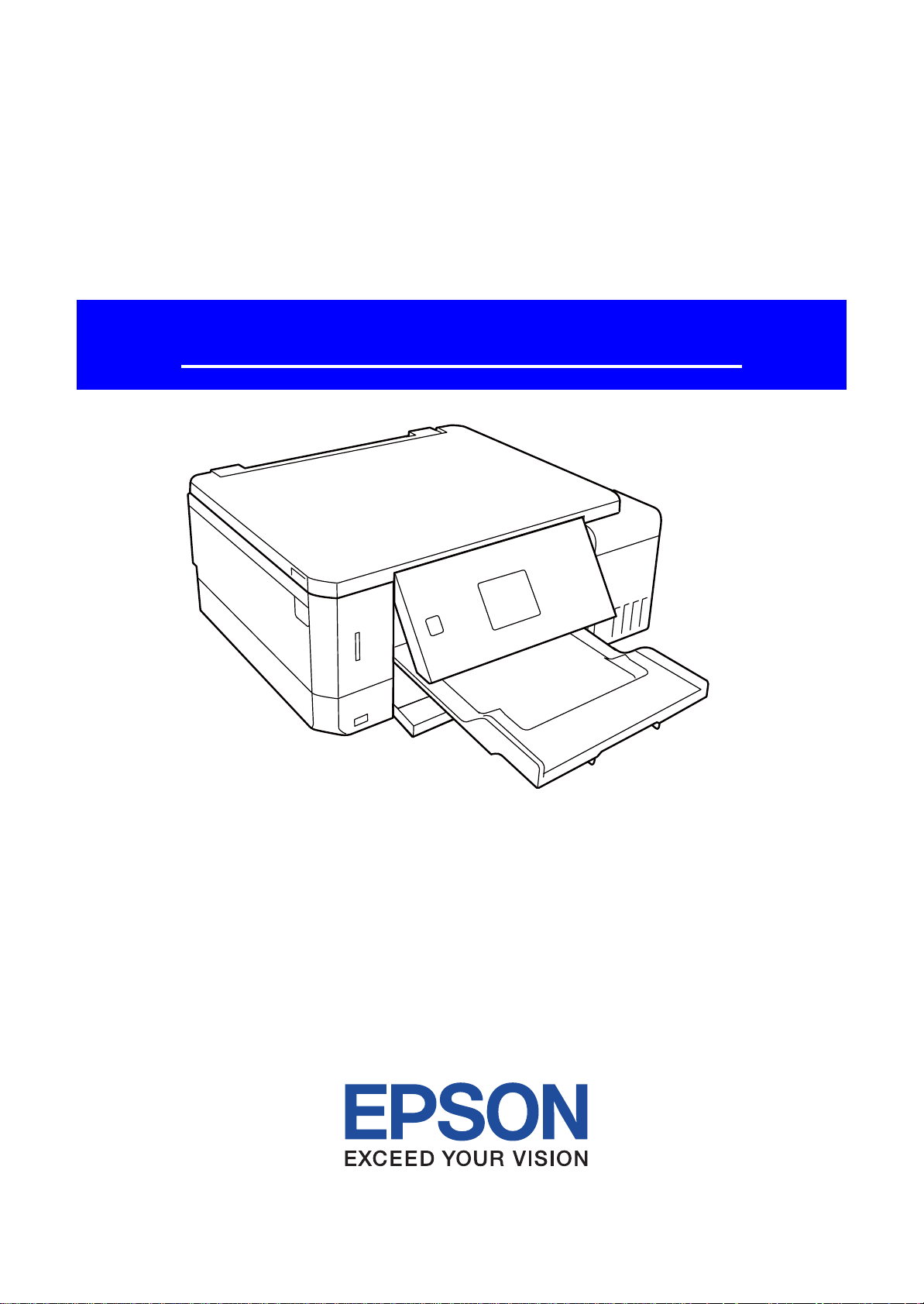
Color Inkjet Printer
Epson ET-7700/L7160
CONFIDENTIAL
SEMF16-014
Page 2

Notice:
All rights reserved. No part of this manual may be reproduced, stored in a retrieval system, or transmitted in any form or
by any means, electronic, mechanical, photocopying, recording, or otherwise, without the prior written permission of
SEIKO EPSON CORPORATION.
All effort have been made to ensure the accuracy of the contents of this manual. However, should any errors be
detected, SEIKO EPSON would greatly appreciate being informed of them.
The contents of this manual are subject to change without notice.
The above not withstanding SEIKO EPSON CORPORATION can assume no responsibility for any errors in this
manual or the consequences thereof.
EPSON is a registered trademark of SEIKO EPSON CORPORATION.
Note :Other product names used herein are for identification purpose only and may be trademarks or r egistered
trademarks of their respective owners. EPSON disclaims any and all rights in those marks.
Copyright 2017 SEIKO EPSON CORPORATION
P-CS Quality Assurance Department
Confidential
Page 3

Safety Precautions
All safety procedures described here shall be strictly adhered to by all parties servicing and maintaining this
product.
DANGER
Strictly observe the following cautions. Failure to comply could result in serious bodily injury or loss of life.
1. Always disconnect the product from the power source and peripheral devices when servicing the product or
performing maintenance.
2. When performing works described in this manual, do not connect to a power source until instructed to do so.
Connecting to a power source causes high voltage in the power supply unit and some electronic components
even if the product power switch is off. If you need to perform the work with the power cable connected to a
power source, use extreme caution to avoid electrical shock.
WARNING
Strictly observe the following cautions. Failure to comply may lead to personal injury or loss of life.
1. Always wear protective goggles for disassembly and reassembly to protect your eyes from ink in working. If
any ink gets in your eyes, wash your eyes with clean water and consult a doctor immediately.
2. When using compressed air products; such as air duster, for cleaning during repair and maintenance, the use
of such products containing flammable gas is prohibited.
PRECAUTIONS
Strictly observe the following cautions. Failure to comply may lead to personal injury or damage of the product.
1. Repairs on Epson product should be performed only by an Epson certified repair technician.
2. No work should be performed on this product by persons unfamiliar with basic safety knowledge required for
electrician.
3. The power rating of this product is indicated on the serial number/rating plate. Never connect this product to
the power source whose voltages is different from the rated voltage.
4. Replace malfunctioning components only with those components provided or approved by Epson;
introduction of second-source ICs or other non-approved components may damage the product and void any
applicable Epson warranty.
5. The capacitors on the Main Board may be electrically charged right after the power turns off or after driving
motors which generates counter electromotive force such as when rotating the PF Roller or when moving the
CR Unit. There is a risk to damage the Main Board if the Head FFC is short-circuited with the capacitors on
the Main Board electrically charged, therefore, after the power turns off or after motors are driven, leave the
printer untouched for approximately 30 seconds to discharge the capacitors before starting disassembly/
reassembly.
6. To prevent the circuit boards from short-circuiting, be careful about the following when handling FFC or
cables.
When handling FFC, take care not to let the terminal section of FFC touch metal parts.
When connecting cables/FFC to the connectors on circuit boards, connect them straight to the connectors to avoid
slant insertion.
Confidential
Page 4

7. In order to protect sensitive microprocessors and circuitry, use static discharge equipment, such as anti-static
wrist straps, when accessing internal components.
8. Do not tilt this product immediately after initial ink charge, especially after performing the ink charge several
times. Doing so may cause ink to leak from the product because it may take some time for the waste ink pads
to completely absorb ink wasted due to the ink charge.
9. Never touch the ink or wasted ink with bare hands. If ink comes into contact with your skin, wash it off with
soap and water immediately. If you have a skin irritation, consult a doctor immediately.
10. When disassembling or assembling this product, make sure to wear gloves to avoid injuries from metal parts
with sharp edges.
11. Use only recommended tools for disassembling, assembling or adjusting the printer.
12. Observe the specified torque when tightening screws.
13. Be extremely careful not to scratch or contaminate the following parts.
Nozzle plate of the Printhead
CR Scale
PF Scale
Coated surface of the PF Roller
Gears
Rollers
LCD
Scanner Sensor
Exterior parts
14. Never use oil or grease other than those specified in this manual. Use of different types of oil or grease may
damage the component or give bad influence on the printer function.
15. Apply the specified amount of grease described in this manual.
16. Make the specified adjustments when you disassemble the printer.
17. When cleaning this product, follow the procedure described in this manual.
18. When transporting this product after filling the ink in the printhead, pack the printer without removing the
ink cartridges in order to prevent the printhead from drying out.
19. Make sure to install antivirus software in the computers used for the service support activities.
20. Keep the virus pattern file of antivirus software up-to-date.
21. When disassembling/reassembling this product, if you find adhesive power of the double-sided tape which
secure the parts or FFC is not enough, replace the tape with new one and attach it correctly to the specified
points where the parts or FFC should be secured.
22. Unless otherwise specified in this manual, the labels attached on the returned product should be transferred to
the corresponding attachment positions on the new one referring to the labels on the returned product.
Confidential
Page 5

About This Manual
This manual, consists of the following chapters, is intended for repair service personnel and includes information
necessary for properly performing maintenance and servicing the product.
CHAPTER 1. TROUBLESHOOTING
Describes the step-by-step procedures for the troubleshooting.
CHAPTER 2. DISASSEMBLY / REASSEMBLY
Describes the disassembly/reassembly procedures for main parts/units of the product, and provides the
standard operation time for servicing the product.
CHAPTER 3. ADJUSTMENT
Describes the required adjustments for servicing the product.
CHAPTER 4. MAINTENANCE
Describes maintenance items and procedures for servicing the product.
CHAPTER 5. APPENDIX
Provides the following additional information for reference:
Connector Diagram
Protection for Transportation
Symbols Used in this Manual
Various symbols are used throughout this manual either to provide additional information on a specific topic or
to warn of possible danger present during a procedure or an action. Pay attention to all symbols when they are
used, and always read explanation thoroughly and follow the instructions.
Indicates an operating or maintenance procedure, practice or condition that, if not strictly observed,
could result in serious injury or loss of life.
Indicates an operating or maintenance procedure, practice, or condition that, if not strictly observed,
could result in bodily injury, damage or malfunction of equipment.
May indicate an operating or maintenance procedure, practice or condition that is necessary to
accomplish a task efficiently. It may also provide additional information that is related to a specific
subject, or comment on the results achieved through a previous action.
For Chapter 2 “Disassembly/Reassembly”, symbols other than indicated above are used to show additional
information for disassembly/reassembly. For the details on those symbols, see "2.3 Disassembly/Reassembly
Procedures (p31)".
Confidential
Page 6

Revision Status
Revision Date of Issue Description
A 2017.3.24 First Release
B 2017.11.14 Addition of Printer Inspection Mode (Service Mode).
C 2018.5.1 Addition of caution in 2.3.2.1 Procedure 1, 2.3.2.2 Procedure 2 of 2.3.2 Required work before
disassembling Adapter Assy and in 2.3.3 Required work before disassembling Ink tank
Addition of caution about performing Ink flushing in 2.3.2.1 Procedure 1 of 2.3.2 Required work
before disassembling Adapter Assy
Addition of caution about Ink charge in 3.1 Required Adjustments
Addition of required adjustment for removing and replacing PW sensor in 3.1 Required
Adjustments
D 2018.7.24 Addition of product name.
Confidential
Page 7

Epson ET-7700/L7160
Chapter 1 Troubleshooting
1.1 Troubleshooting....................................................................................................................................................... 10
1.1.1 Troubleshooting Workflow ............................................................................................................................ 10
1.2 Power-On Sequence ................................................................................................................................................ 13
1.3 Fatal Error Code List ............................................................................................................................................... 15
1.3.1 Displaying the Fatal Error Code..................................................................................................................... 15
1.3.2 Printer Fatal Error Code ................................................................................................................................. 16
Chapter 2 Disassembly/Reassembly
2.1 Overview ................................................................................................................................................................. 21
2.1.1 Tools ............................................................................................................................................................... 21
2.1.2 Jigs .................................................................................................................................................................. 21
2.1.3 Locations of the Parts/Units ........................................................................................................................... 22
2.1.4 Standard Operation Time for Servicing the Product ...................................................................................... 25
2.2 Common cautions when disassembling/reassembling the Product ......................................................................... 29
2.3 Disassembly/Reassembly Procedures ..................................................................................................................... 31
2.3.1 Parts/units to be removed before disassembly and reassembly...................................................................... 31
2.3.2 Required work before disassembling Adapter Assy....................................................................................... 32
2.3.2.1 Procedure 1 ............................................................................................................................................ 32
2.3.2.2 Procedure 2 ............................................................................................................................................ 33
2.3.3 Required work before disassembling Ink tank ............................................................................................... 35
2.3.4 Printer Inspection Mode (Service Mode) ....................................................................................................... 37
2.3.5 Disassembly Flowchart................................................................................................................................... 38
2.3.5.1 Disassembly Flowchart (ET-7700/L7160) ............................................................................................ 39
2.4 Detailed Disassembly/Reassembly Procedure for each Part/Unit........................................................................... 47
2.5 Routing FFCs/cables ............................................................................................................................................... 54
Revision D
Contents
Chapter 3 Adjustment
3.1 Required Adjustments ............................................................................................................................................. 60
3.2 Adjustment Program................................................................................................................................................ 69
3.2.1 Operating Environment .................................................................................................................................. 69
3.2.2 Details of the Adjustment Program ................................................................................................................ 69
3.2.2.1 CR Motor Heat Protection Control / PF Motor Heat Protection ........................................................... 69
3.2.2.2 Scanner Motor Heat Protection.............................................................................................................. 70
3.2.2.3 Photo sensor light level adjustment ....................................................................................................... 70
3.2.2.4 Initialize PW deterioration offset........................................................................................................... 71
3.2.2.5 MAC Address Setting ............................................................................................................................ 72
3.2.2.6 Head angular adjustment ....................................................................................................................... 73
3.3 Mechanism Adjustment / Check ............................................................................................................................. 74
3.3.1 Checking the Platen Gap ................................................................................................................................ 74
3.3.1.1 PG Adjustment procedure...................................................................................................................... 74
3.3.1.2 Preparation ............................................................................................................................................. 75
3.3.1.3 Adjustment procedure ............................................................................................................................ 76
Chapter 4 Maintenance
4.1 Overview ................................................................................................................................................................. 79
4.1.1 Cleaning the Printhead.................................................................................................................................... 79
4.1.1.1 Cleaning the printhead filter .................................................................................................................. 80
4.1.1.2 Cleaning the seal rubber section of the printhead.................................................................................. 81
4.1.1.3 Cleaning the nozzle plate section of the printhead ................................................................................ 82
7
Confidential
Page 8

Epson ET-7700/L7160
4.1.2 Cleaning the Carriage ..................................................................................................................................... 83
4.1.3 Cleaning the Exterior Parts/inside of the printer ............................................................................................ 84
4.2 Lubrication .............................................................................................................................................................. 85
4.2.1 Lubrication Points and Instructions................................................................................................................ 86
Chapter 5 Appendix
5.1 Connector Diagram ................................................................................................................................................. 93
5.1.1 Connector Diagram for ET-7700/L7160 ........................................................................................................ 93
5.2 Protection for Transportation .................................................................................................................................. 94
5.2.1 Securing the CR Unit...................................................................................................................................... 94
5.2.2 Securing the Duplex Unit ............................................................................................................................... 95
5.2.3 Securing the SCN ........................................................................................................................................... 96
Revision D
8
Confidential
Page 9

CHAPTER 1
TROUBLESHOOTING
Confidential
Page 10
Epson ET-7700/L7160
Printer failure only
*: In case of “Not Trouble Found”, check fatal error code.
Finish
*
Does the printer work
without any other trouble?
Yes
No
5
Is scanning operation
finished without
trouble?
What is returned reason?
2
Print check pattern
Yes
No
Yes
No
Yes
No
Is Power-on sequence
finished without error?
Does the printer enter
standby state without error?
3
Does an error occur
when printing?
Start
Turn on the power
1
No
Does printer turn on the
power?
Yes
4
Is printing operation
finished without trouble?
(p 11)
(p 11)
(p 12)
(p 11)
(p 11)
Copy an image
A
(p 11)
Yes
(p 11)
B
No
1.1 Troubleshooting
This section describes the troubleshooting workflow and fatal error information.
1.1.1 Troubleshooting Workflow
The following page describes the troubleshooting workflow. Follow the flow when troubleshooting problems.
This flowchart is compiled based on the following contents.
• Our experience regarding the quality problem.
• ESK’s repair data.
• Printer Mechanism specification for the product.
If the reason for the return is evident, first check the phenomenon user claims recurs,
then proceed to the troubleshooting.
Revision D
Figure 1-1. Troubleshooting Workflow (1)
Troubleshooting Troubleshooting Workflow 10
Confidential
Page 11
Epson ET-7700/L7160 Revision D
1
No Power
[Presumable Cause]
• PS Unit damage
• Main Board damage
• Panel Board damage
[Major Troubleshooting]
• PS Unit replacement
• Main Board replacement
• Panel Board replacement
*
The power-on sequence
does not start
(p 10)
Please refer to " 1.3 Fatal Error
Code List (p15)".
Fatal error
Error is indicated during power-on
2
sequence.
*: If the printer can turn on but turns off right away, the protection
circuit may cut off the power due to an error such as a circuit
failure.
Problems related to print result or during printing (p 10)
4 5
(p 10)
Maintenance error
[Occurrence Condition]
This error occurs when
maintenance counter in the
Maintenance Box exceeds the
specified value or when the
counter for waste ink pad for
borderless printing in the printer
exceeds the specified value.
[Major Occurrence Timing]
• Power-on timing
• Print start timing
• Paper eject timing
• Cleaning timing
[Troubleshooting]
Maintenance Box
• Maintenance Box replacement
Borderless printing waste pad
• Borderless printing waste pad
replacement
• Maintenance counter reset
Ink End error
[Occurrence Condition]
This error occurs when the ink
consumption counter reaches the
threshold value of ink end.
[Major Occurrence Timing]
• Power-on timing
• Print start timing
• Paper eject timing
• Cleaning timing
[Troubleshooting]
Ink counter reset (to reset ink
remaining amount)
Paper Jam error
[Occurrence Condition]
This error occurs when PW
Sensor or CR Motor does not
work.
[Major Occurrence Timing]
Power-on timing
[Troubleshooting]
• PW Sensor FFC reconnection
• PW Sensor replacement
• CR Motor cable reconnection
• CR Motor replacement
Scanning cannot
be performed
successfully
(p 10)
Printer does not enter
standby state normally. (p 10)
A
2nd Bin
[Presumable Cause]
2nd bin is ejected.
[Major Occurrence Timing]
Power-on timing
[Major Troubleshooting]
• 2nd bin detection sensor FFC
reconnection
• 2nd bin detection sensor
replacement
Other errors
(p 10)
B
Maintenance Box
[Presumable Cause]
Message indicating
Maintenance Box is not
installed appears.
[Major Occurrence Timing]
Power-on timing
[Major Troubleshooting]
• Maintenance Box Installation
• Ink Eject CSIC Cable
reconnection
• CSIC Connector replacement
Poor Printing
[Phenomenon]
• Poor printing quality
• Ink stain on paper
•Dot missing
• Paper eject without printing
• Blank page
[Presumable Cause]
• Driver / Panel mis-setting
• Contamination of CR scale
• Contamination of PF Roller
• Contamination of Printhead cover
• Printhead damage
• Ink clogging of Printhead
• Contamination on Cap Unit / Wiper of Ink
System Assy
• Ink System Assy damage
• Float of Porous Pad on Paper Guide Front
• Narrower PG
• PE Sensor damage
• PW Sensor damage
• PE Sensor FFC connection failure
• ASF PE Sensor FFC connection failure
• ASF PE Sensor damage
• Adapter tube is caught or pressed flat
• Air chamber tube is caught or pressed flat
• Air Chamber Ink Supply ventilation film is wet
with ink
[Major Troubleshooting]
• Driver / Panel re-setting
• CR Scale replacement
• Printhead cover cleaning
• Printhead cleaning
• Printhead replacement
• Rubber cleaning of Cap Unit
• Ink System Assy replacement
• Porous Pad re-installation
• Printer Mechanism replacement
• PE Sensor replacement
•PG readjustment
• PW Sensor replacement
• Main Board replacement
• PE Sensor FFC reconnection
• ASF PE Sensor FFC reconnection
• ASF PE Sensor replacement
• Improve Adapter tube’s pressed or caught
condition
• Improve Air chamber tube’s pressed or caught
condition
• Air Chamber Ink Supply replacement
Poor Paper Loading
[Presumable Cause]
• Use of 3rd party media
• Edge guide mis-setting
• Foreign material
• Part come-off
• Contamination of paper feed
roller on Pickup Roller or
Duplex Unit
• Paper Cassette Assy damage
• Contamination of PF Roller
[Major Troubleshooting]
• Recommendation of EPSON
media
• Edge guide re-setting
• Foreign material removal
• Part re-installation
• Pickup Roller replacement
• Duplex Unit replacement
• Paper Cassette Assy
replacement
• Printer Mechanism
replacement
Abnormal Noise
[Presumable Cause]
• Foreign material
• Insufficient grease
•Gear damage
[Major Troubleshooting]
• Foreign material removal
• Lubrication of grease
• Gear replacement
Other Errors
[Presumable Cause]
Message that prompts the user to
pull out the stacker does not
appear even though the stacker is
retracted.
[Major Troubleshooting]
• Stacker open sensor cable
reconnection
• Stacker open sensor
replacement
Scanner failure
[Presumable Cause]
• Contamination of Scanner
Glass
• Contamination of Document
Pad
• CIS Unit damage
• Contamination of Scanner
Motor encoder scale
• Scanner Motor encoder
damage
• Scanner Motor damage
[Major Troubleshooting]
• Scanner Glass cleaning
• Document Pad cleaning
• Document Pad Assy
replacement
• CIS Unit replacement
• Scanner Motor encoder
cleaning
• Scanner Motor encoder
replacement
• Scanner Motor replacement
Tank Cover
[Presumable Cause]
Message that prompts the user to
refresh ink remaining information
does not appear even though Tank
Cover Assy is opened.
[Major Troubleshooting]
• Cover Tank open sensor cable
reconnection
• Cover Tank open sensor
replacement
1st Bin
[Presumable Cause]
Message that prompts the user to
set paper does not appear even
though 1st bin is removed.
[Major Troubleshooting]
• 1st bin detection sensor FFC
reconnection
• 1st bin detection sensor
replacement
Figure 1-2. Troubleshooting Wo rkflow (2)
Troubleshooting Troubleshooting Workflow 11
Confidential
Page 12

Epson ET-7700/L7160 Revision D
Error is indicated during printing nozzle check pattern.(p 10)
3
Paper Jam error
[Occurrence Condition]
This error occurs when top/
bottom of paper is not detected by
ASF PE Sensor or PE Sensor in
the specified steps of paper
loading / ejecting operation
correctly.
[Major Occurrence Timing]
• Power-on timing
• Paper loading timing
• Paper eject timing
[Major Troubleshooting]
1 Push “Start” button after the
jammed paper in printer
mechanism is removed.
2 If this error occurs again,
check foreign materials / parts
come-off / parts damage / parts
deformation in paper path.
3 If this is not solved by 2),
check the following parts.
• ASF PE sensor (Paper Guide
Rear ASF Assy)
•PE sensor
• Main board
*If this error occurs during auto
duplex print operation, printer stops
and ejects the paper automatically
even if the printing is not com-
pleted.
No Paper error
[Occurrence Condition]
This error occurs when top of
paper is not detected by ASF PE
Sensor or PE Sensor in the
specified steps of paper loading
operation correctly.
[Major Occurrence Timing]
• Paper loading timing (Front /
Rear)
[Major Troubleshooting]
1 Set paper in Cassette Assy and
push “Start” button.
2 If this error occurs again,
check foreign materials / parts
come-off / parts damage / parts
deformation in paper path.
3 If this is not resolved by 2),
check the following parts.
• Pickup Roller
• Cassette Assy
• Duplex unit
• APG Lever & Gears
• ASF PE Sensor (Paper Guide
Rear ASF Assy)
• PE Sensor
• Main Board
•PF Motor
Double Feed error
[Occurrence Condition]
This error occurs on the following
cases.
• A paper is ejected without
printing during paper loading
operation.
• Actual paper length is longer
than theoretical one.
[Major Occurrence Timing]
• Print start timing
[Troubleshooting]
• PE Sensor replacement
• PW Sensor replacement
• Main Board replacement
*This error occurs only for manual
duplex print.
Paper Size Unmatch error
[Occurrence Condition]
This error occurs when actual
paper size is not matched to
theoretical one.
[Major Occurrence Timing]
• Duplex print timing
• Paper eject timing
[Troubleshooting]
• PE Sensor replacement
• PW Sensor replacement
• Main Board replacement
Paper Detection Size error
[Occurrence Condition]
This error occurs when the actual
paper size is not matched to the
theoretical one. (It occurs when
the gap between the actual paper
size and the specified one is
bigger than
[Major Occurrence Timing]
• Print start timing
[Troubleshooting]
• PE Sensor replacement
• PW Sensor replacement
• Main Board replacement
4mm.)
(except for Duplex print)
Stacker Open error
[Occurrence Condition]
This error occurs when the stacker
open condition is not detected by
stacker open sensor.
[Major Occurrence Timing]
• Power-on timing
• Print start timing
• Paper eject timing
[Troubleshooting]
• Stacker Assy replacement
• Paper Guide Front Assy
replacement
• Main Board replacement
Disc error
[Occurrence Condition]
This error occurs when media is
not detected properly by PW
sensor.
[Major Occurrence Timing]
• Print start timing (CD-R
printing)
[Troubleshooting]
• PW Sensor replacement
• Main Board replacement
Disc Tray error
[Occurrence Condition]
This error occurs when CD-R tray
is not detected properly by PW
sensor.
[Major Occurrence Timing]
• Print start timing (CD-R
printing)
[Troubleshooting]
• PW Sensor replacement
• Main Board replacement
Stacker Close error
[Occurrence Condition]
This error occurs when stacker is
not detected by stacker close
sensor.
[Major Occurrence Timing]
• Print start timing (CD-R
printing)
[Troubleshooting]
• Stacker Close Sensor
replacement
• Main Board replacement
CD-R Request error
[Occurrence Condition]
This error occurs when printer
does not receive the signal to
begin CD-R tray feed.
[Major Occurrence Timing]
• Print start timing (CD-R
printing)
[Troubleshooting]
• Main Board replacement
Figure 1-3. Troubleshooting Wo rkflow (3)
Troubleshooting Troubleshooting Workflow 12
Confidential
Page 13

Epson ET-7700/L7160
080
CR Unit
APG lever CR Lock
HP
PGTyp.
PG++
080 HP
PGTyp.
PG++
080 HP
PGTyp.
PG++
1.2 Power-On Sequence
This section describes the power-on sequences. The preconditions are as follows.
Condition: Power-on sequence (See Table 1-1.)
No error occurred when you turned on the printer last time and it has been correctly turned off.
Initial ink charge has finished and every cartridge has sufficient ink.
No paper on the paper path.
The Printhead is capped.
The Carriage is normally fixed by the CR Lock.
Maintenance error recovery has never been performed.
1st Cassette Assy is in front of the printer.
Rear paper load cover is closed.
CD-R tray is not inserted.
Table 1-1. Condition 1: Normal Power-on Sequence
Operation
1. Printhead initialization and fuse inspection
1-1.Initializes the Printhead, and checks for the fuse on the circuit boards in the printer.
2. Checking for waste ink overfl ow
2-1.Checks the waste ink counter if the waste ink overflow is occurring.
*1
*3
Revision D
CR Unit/PF Roller
movement and
position
*2
3. Releasing the CR lock
3-1.The PF Motor rotates clockwise and releases the CR lock.
4. Seeking the home position
4-1.The CR Unit moves to the 0-digit side slowly and confirms it touches the Right Frame.
4-2.The CR Unit moves to the 80-digit side slowly and stops near the right side of the Paper Guide Front Assy and
confirms it does not touch the foreign material, such as remaining paper.
4-3.The PF Motor rotates clockwise so that the APG Lever is reset securely.
4-4.The CR Unit moves to the home position quickly.
4-5.The distance from the position where the CR Unit touched to the Left Frame is regarded as the standard distance
from the origin position, and the home position is fixed. From then on, the CR Unit position is monitored according
to the signals from the CR Encoder.
4-6.The CR Unit moves to the home position slowly.
5. Low temperature operation sequence *
4
5-1.The CR Unit moves back and forth quickly between the CR Unit and near the left frame for two times.
6. APG Shift Operation
6-1.The CR Unit moves to near the left frame quickly.
6-2.The PF Motor rotates counterclockwise to set the APG Lever.
6-3.The CR Unit moves to the 0-digit side slowly to set PG from PG++ to PG Typ.
6-4.The CR Unit moves to near the left frame quickly.
080 HP
PG++
PGTyp.
080 HP
PG++
PGTyp.
080 HP
PG++
PGTyp.
080 HP
PG++
PGTyp.
080 HP
PG++
PGTyp.
080 HP
PG++
PGTyp.
080 HP
PG++
PGTyp.
080 HP
PG++
PGTyp.
080 HP
PG++
PGTyp.
080 HP
PG++
PGTyp.
080 HP
PG++
PGTyp.
Troubleshooting Power-On Sequence 13
Confidential
Page 14

Epson ET-7700/L7160
Table 1-1. Condition 1: Normal Power-on Sequence
6-5.The PF Motor rotates clockwise to reset the APG Lever.
7. CR lock setting
7-1.The CR Unit moves to the home position.
7-2.The PF Motor rotates counterclockwise to lock the CR Unit with the CR Lock.
Note *1: The rotation directions of the PF Motor are as follows.
Clockwise: Paper is fed normally
Counterclockwise: Paper is fed backward
*2: The conditions of the CR lock and the APG lever are as follows.
• CR lock
Red: CR lock is set
White: CR lock is released
• APG Lever
Red: APG Lever is set (PG can be changed)
White: APG Lever is reset
*3: The fatal error occurs if there is a problem such as the fuse blew.
*4: Executed when the detected temperature is under 5
*5: The empty suction operation may occur depending on situations.
Operation
*1
o
C (41oF) by the thermistor on the Printhead.
Revision D
CR Unit/PF Roller
movement and
position
*2
080 HP
PG++
PGTyp.
080 HP
PG++
PGTyp.
080 HP
PG++
PGTyp.
The printer operation related to the maintenance error recovery is as follows.
• When the waste ink counter reaches the threshold value (1) for the first time and the
maintenance error occurs, the counter threshold of the maintenance error is changed
to threshold value 2 after performing recovery from the maintenance error.
• After the threshold value (2) is enabled, the warning; to notify the possibility of ink
leakage out of the printer, is displayed every time the waste ink counter increases by
5%.
• If the waste ink counter reaches the threshold value (2), the maintenance error occurs.
Then, the waste ink counter is changed back to the threshold value (1) after recovering
from the maintenance error, and the warning is displayed repeatedly according to the
increment of the waste ink counter until the maintenance error occurs when the
threshold value (2) is reached.
(Recovery from the maintenance error can be performed up to the specified number
of times.)
Troubleshooting Power-On Sequence 14
Confidential
Page 15
Epson ET-7700/L7160
Error Code
LCD display screen image
1.3 Fatal Error Code List
This section describes how to check the fatal error code, description, and the possible causes.
1.3.1 Displaying the Fatal Error Code
The fatal error code is stored in the EEPROM on the Main Board and can be read out using the Adjustment
Program. This product displays a printer fatal error code automatically on the panel LCD when a printer fatal
error occurs.
Revision D
Figure 1-2. Displaying the Fatal Error Code
Troubleshooting Fatal Error Code List 15
Confidential
Page 16

Epson ET-7700/L7160
1.3.2 Printer Fatal Error Code
This section describes the fatal error code and the possible cause for this product.
Revision D
Error type
Scanner
Error
code
100016 HP detection failure
100017 Contact detection distance exceeded
100018
100019
100020 Measurement error
100032 LED light failure
100065 FB PID excess speed
100066 FB PID reverse
100067 FB PID lock
100068 FB PID acceleration lock
100069 FB PID excess load
100070 FB PID driving time
Opposite side contact detection distance
exceeded
Wrong opposite side contact detection
distance
Error name Possible cause
White reference or origin pattern could not be read.
• CIS Unit failure
• Scanner Housing failure
• Main Board failure
• Scanner FFC(CIS) bad contact, broken
FB CR can not contact to origin position.
• CR-related gears broken
• Timing belt broken
• Main Board failure (operation in out of control)
• Main Board failure (operation in out of control)
Detected abnormal of motor drive load.
• Overloaded of driving mechanism
CIS module LED failure
• CIS module FFC bad contact, broken
• CIS module failure
• Main Board failure
FB CR Motor was driven at a speed faster than predetermined one.
• FB CR Encoder failure (contaminated bad contact, Encoder Board
failure)
• FB CR Encoder Cable bad contact, broken
• Main Board failure (board control runaway, noise)
Detects that FB CR Motor is being driven in opposite direction to
specified driving direction.
• FB CR Encoder failure (contaminated scale, Encoder Board failure)
• FB CR Encoder Cable bad contact, broken
• Main Board failure (board control runaway, noise)
FB CR Motor does not rotate.
• FB CR Encoder failure (contaminated scale, Encoder Board failure)
• FB CR Encoder Cable bad contact, broken, disconnected
• FB CR Motor failure
• Foreign material
• Main Board failure
• Locking of FB CR mechanism
FB CR Motor does not rotate.
• FB CR Encoder failure (contaminated scale, Encoder Board failure)
• FB CR Encoder Cable bad contact, broken, disconnected
• FB CR Motor failure
• Foreign material
• Main Board failure
• Locking of FB CR mechanism
Rotation speed of FB CR is different from specified speed.
• FB CR Encoder failure (contaminated scale, Encoder Board failure)
• FB CR Encoder Cable bad contact, broken, disconnected
• FB CR Motor failure
• Foreign material
• Main Board failure
• Overloaded of FB CR mechanism
Detects that driving period of FB CR is irregularly long.
• Firmware failure, runaway
• Main Board failure (if error recurs in power ON/OFF)
Troubleshooting Fatal Error Code List 16
Confidential
Page 17

Epson ET-7700/L7160
Revision D
Error type
Scanner
Printer
Error
code
100073 FB BS+ excess speed
100074 FB BS+ reverse
100075 FB BS+ lock
100077 FB BS+ excess load
100078 FB BS+ driving time
000020 CR PID excess driving time error
000021 CR PID excess load error
000022 CR PID excess speed error
000023 CR PID reverse error
000024 CR PID lock error
Error name Possible cause
FB CR Motor was driven at a speed faster than predetermined one
during high-resolution scanning.
• FB CR Encoder failure (contaminated scale, Encoder Board failure)
• FB CR Encoder Cable bad contact, broken
• Main Board failure (board control runaway, noise)
Detects that FB CR Motor is being driven in opposite direction to
specified driving direction during high-resolution scanning.
• FB CR Encoder failure (contaminated scale, Encoder Board failure)
• FB CR Encoder Cable bad contact, broken
• Main Board failure (board control runaway, noise)
FB CR Motor does not rotate during high-resolution scanning.
• FB CR Encoder failure (contaminated scale, Encoder Board failure)
• FB CR Encoder Cable bad contact, broken, disconnected
Rotation speed of FB CR is different from specified speed during
high-resolution scanning.
• FB CR Encoder failure (contaminated scale, Encoder Board failure)
• FB CR Encoder Cable bad contact, broken, disconnected
• FB CR Motor failure
•Foreign material
• Main Board failure
• Overloaded of FB CR mechanism
Detects that driving period of FB CR is irregularly long during
high-resolution scanning.
• Firmware failure, runaway
• Main Board failure (if error recurs in power ON/OFF)
Detects that driving period of CR is irregularly long.
• Firmware failure, runaway
• Main Board failure (if error recurs in power ON/OFF)
Rotation speed of CR is different from specified speed.
• CR Encoder failure (contaminated scale, Encoder Board failure)
• CR Encoder Cable bad contact, broken, disconnected
• CR Motor failure
•Foreign material
• Main Board failure
• Overloaded of CR mechanism
CR Motor was driven at a speed faster than predetermined one.
• CR Encoder failure (contaminated scale, Encoder Board failure)
• CR Encoder Cable bad contact, broken
• Main Board failure (board control runaway, noise)
Detects that CR Motor is being driven in opposite direction to
specified driving direction.
• CR Encoder failure (contaminated scale, Encoder Board failure)
• CR Encoder Cable bad contact, broken
• Main Board failure (board control runaway, noise)
CR Motor does not rotate.
• CR Encoder failure (contaminated scale, Encoder Board failure)
• CR Encoder Cable bad contact, broken, disconnected
• CR Motor failure
•Foreign material
• Main Board failure
• Locking of CR mechanism
Troubleshooting Fatal Error Code List 17
Confidential
Page 18

Epson ET-7700/L7160
Revision D
Error type
Printer
Error
code
000025 CR PID speed fall error
000030
000031 CR load position excess load error
000032 CR load position excess speed error
000033 CR load position reverse error
000040 PF PID driving time error
000041 PF PID excess load error
000042 PF PID excess speed error
000043 PF PID reverse error
000044 PF PID lock error
CR load position excess driving time
error
Error name Possible cause
Rotation speed of CR is slower than specified speed.
• CR Encoder failure (contaminated scale, Encoder Board failure)
• CR Encoder Cable bad contact, broken, disconnected
• CR Motor failure
• Foreign material
• Main Board failure
• Overloaded of CR mechanism
Detects that driving period of CR is irregularly long (in specific
slow speed rotation).
• Firmware failure, runaway
• Main Board failure (if error recurs in power ON/OFF)
Rotation speed of CR is different from specified speed (in specific
slow speed rotation).
• CR Encoder failure (contaminated scale, Encoder Board failure)
• CR Encoder Cable bad contact, broken, disconnected
• CR Motor failure
• Foreign material
• Main Board failure
• Overloaded of CR mechanism
CR Motor was driven at a speed faster than predetermined one (in
specific slow speed rotation).
• CR Encoder failure (contaminated scale, Encoder Board failure)
• CR Encoder Cable bad contact, broken
• Main Board failure (board control runaway, noise)
Detects that CR Motor is being driven in opposite direction to
specified driving direction (in specific slow speed rotation).
• CR Encoder failure (contaminated scale, Encoder Board failure)
• FB CR Encoder Cable bad contact, broken
• Main Board failure (board control runaway, noise)
Detects that driving period of PF is irregularly long.
• Firmware failure, runaway
• Main Board failure (if error recurs in power ON/OFF)
Rotation speed of PF is different from specified speed.
• PF Encoder failure (contaminated scale, Encoder Board failure)
• PF Encoder Cable bad contact, broken, disconnected
• PF Motor failure
• Foreign material
• Main Board failure
• Overloaded of PF mechanism
PF Motor was driven at a speed faster than predetermined one.
• PF Encoder failure (contaminated scale, Encoder Board failure)
• PF Encoder Cable bad contact, broken
• Main Board failure (board control runaway, noise)
Detects that PF Motor is being driven in opposite direction to
specified driving direction.
• PF Encoder failure (contaminated scale, Encoder Board failure)
• PF Encoder Cable bad contact, broken
• Main Board failure (board control runaway, noise)
PF Motor does not rotate.
• PF Encoder failure (contaminated scale, Encoder Board failure)
• PF Encoder Cable bad contact, broken, disconnected
• PF Motor failure
• PF Motor cable bad contact, broken
• Foreign material
• Main Board failure
• Locking of PF mechanism
Troubleshooting Fatal Error Code List 18
Confidential
Page 19

Epson ET-7700/L7160
Revision D
Error type
Printer
System error
Error
code
Error name Possible cause
Detects that driving period of PF is irregularly long (in specific slow
000050
PF load position excess driving time
error
speed rotation).
• Firmware failure, runaway
• Main Board failure (if error recurs in power ON/OFF)
Rotation speed of PF is different from specified speed (in specific
slow speed rotation).
• PF Encoder failure (contaminated scale, Encoder Board failure)
000051 PF load position excess load error
• PF Encoder Cable bad contact, broken, disconnected
• PF Motor failure
• Foreign material
• Main Board failure
• Overloaded of PF mechanism
PF Motor was driven at a speed faster than predetermined one (in
specific slow speed rotation).
000052 PF load position excess speed error
• PF Encoder failure (contaminated scale, Encoder Board failure)
• PF Encoder Cable bad contact, broken
• Main Board failure (board control runaway, noise)
Detects that PF Motor is being driven in opposite direction to
specified driving direction (in specific slow speed rotation).
000053 PF load position reverse error
030001 PE Detector error • PE Detector failure (in Photo sensor light level adjustment)
030002 PW Detector insufficient light error • PW Detector failure (in Photo sensor light level adjustment)
030003 PE Detector insufficient light error • PE Detector failure (in Photo sensor light level adjustment)
031001 Head hot detect error (pre printing)
031002 Head hot detect error (after flushing)
031003 Transistor temperature error
031004 Head temperature error
031006 Blown headfuse error • Headfuse has blown.
033002 ASIC access error
033004 Fatal error when sending SC
033006 Read parity error
033007 Write parity error
033008 Access mismatch error • Bug of firmware
202620 Wireless board failure • Wireless board is broken.
205102 Card board failure
20**** Firmware failure • Firmware is abnormal.
• PF Encoder failure (contaminated scale, Encoder Board failure)
• PF Encoder Cable bad contact, broken
• Main Board failure (board control runaway, noise)
• Printhead failure
• Main Board failure
• Printhead failure
• Main Board failure
• Head FFC(CN42) bad contact, broken
• Main Board failure
• Disconnection or slant connection of FFC
• Main Board failure
• Disconnection or slant connection of FFC
• Main Board failure
• Disconnection or slant connection of FFC
• Main Board failure
• Disconnection or slant connection of FFC
• Card slot board is broken.
• Card slot FFC bad contact, broken
Troubleshooting Fatal Error Code List 19
Confidential
Page 20

CHAPTER 2
DISASSEMBLY/REASSEMBLY
Confidential
Page 21

Epson ET-7700/L7160
2.1 Overview
This chapter describes procedures for disassembling the main parts/units of this product. Unless otherwise
specified, disassembled parts/units can be reassembled by reversing the disassembly procedure. See the cautions
or tips for disassembly/reassembly described in "2.4 Detailed Disassembly/Reassembly Procedure for each Part/
Unit (p47)".
Read the "Safety Precautions(p3)" before disassembling and reassembling.
When you have to remove units or parts that are not described in this chapter, see the exploded diagrams of SPI
(Service Parts Information).
2.1.1 Tools
Use only specified tools to avoid damaging the printer.
Name Availability EPSON Part Code
(+) Phillips screwdriver #1 O 1080530
(+) Phillips screwdriver #2 O ---
Flathead screwdriver O ---
Flathead Precision screwdriver #1 O ---
Tweezers O ---
Longnose pliers O ---
Acetate tape --- 1003963
Note 1: Some of the tools listed above are commercially available.
2: EPSON provides the tools listed with EPSON part code.
Revision D
2.1.2 Jigs
Name Quantity EPSON Part Code
Thickness gauge (1.1 mm) 2 Commercially available
Thickness gauge (1.3 mm) 2 Commercially available
Box to adjust the height of Ink System Assy
(H: approx. 9 mm)
1 Can be made with a commercial item.
Disassembly/Reassembly Overview 21
Confidential
Page 22
Epson ET-7700/L7160
Front
4
3
6
5
1
2
Right
7
8
Left
9
10
Rear
11
12
13
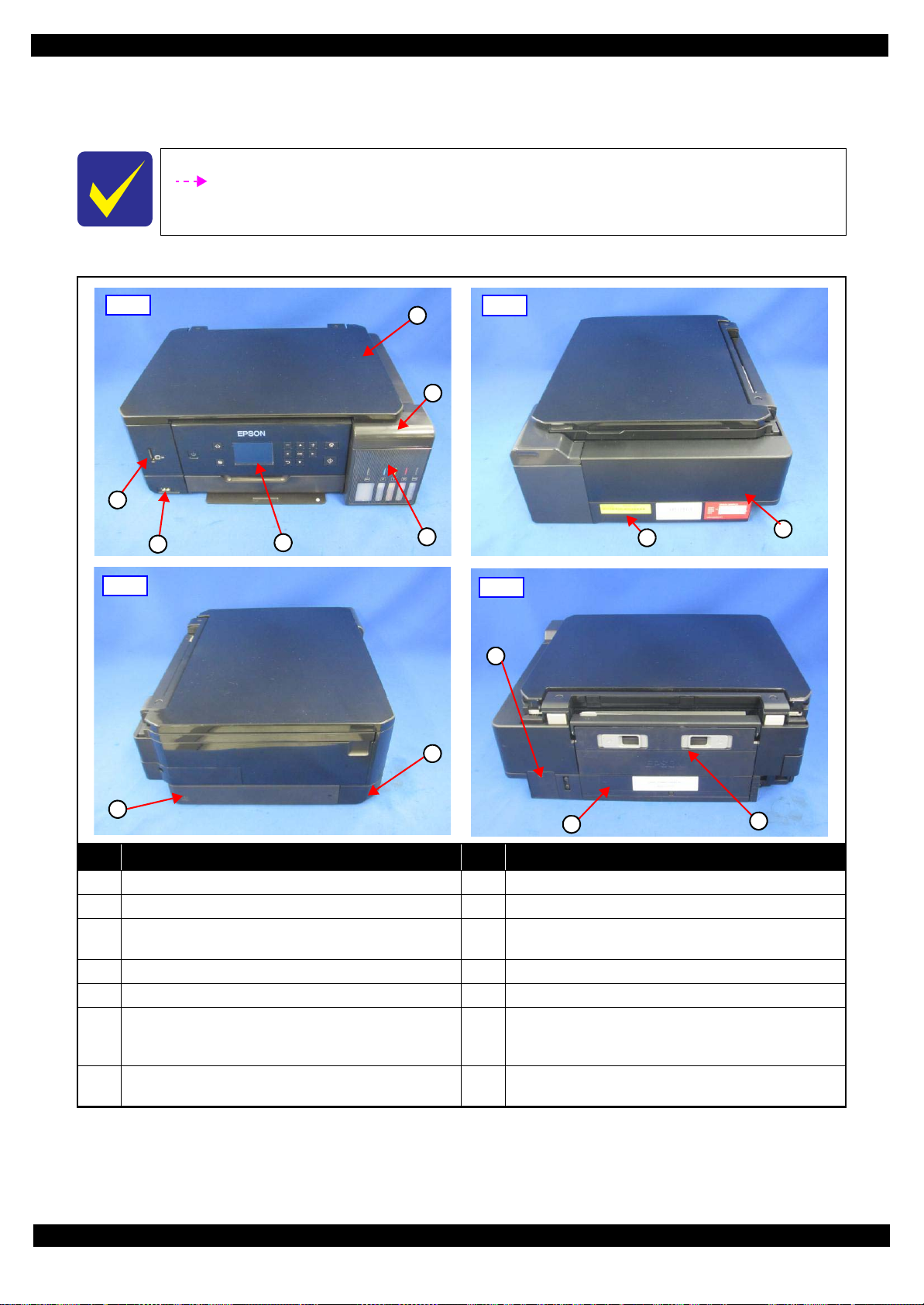
2.1.3 Locations of the Parts/Units
This section shows the locations of the main parts/units of this product.
The parts/units which can not be seen in the following pictures are indicated in dotted lines
().
Exterior parts
Revision D
No. Name No. Name
1 Scanner Unit (p39)/SCN Document Cover Assy (p39) 8 Housing Upper (p39)
2 Tank Cover Assy (p44)/Tank Cap Assy (p44) 9 USB Cover (p39)
Tank Housing Assy (p44)/Ink Supply Tank 100 (p45)/
3
Tank Unit 50 (p45)
4 Panel Assy (p43) 11 Duplex Unit (p43)
5 Left Bottom Housing (p40) 12 Paper Guide Rear ASF Assy (p41)
Left Bottom Housing Assy (p40)/Front Left Housing
6
Disassembly/Reassembly Overview 22
Assy (p43)/Card Slot Board (p43)/Wireless LAN Module
(p43)/Sub Board Assy (p43)
Right Frame Base Assy (p44)/Air Chamber Tube Assy
7
(p45)/CSIC Cable Holder Assy (p45)
Figure 2-1. Exterior Parts
Left Frame Base Assy (w/Main Board) (p40)
10
Maintenance Box Cover (p39)/Maintenance Box (p39)
13
Confidential
Page 23
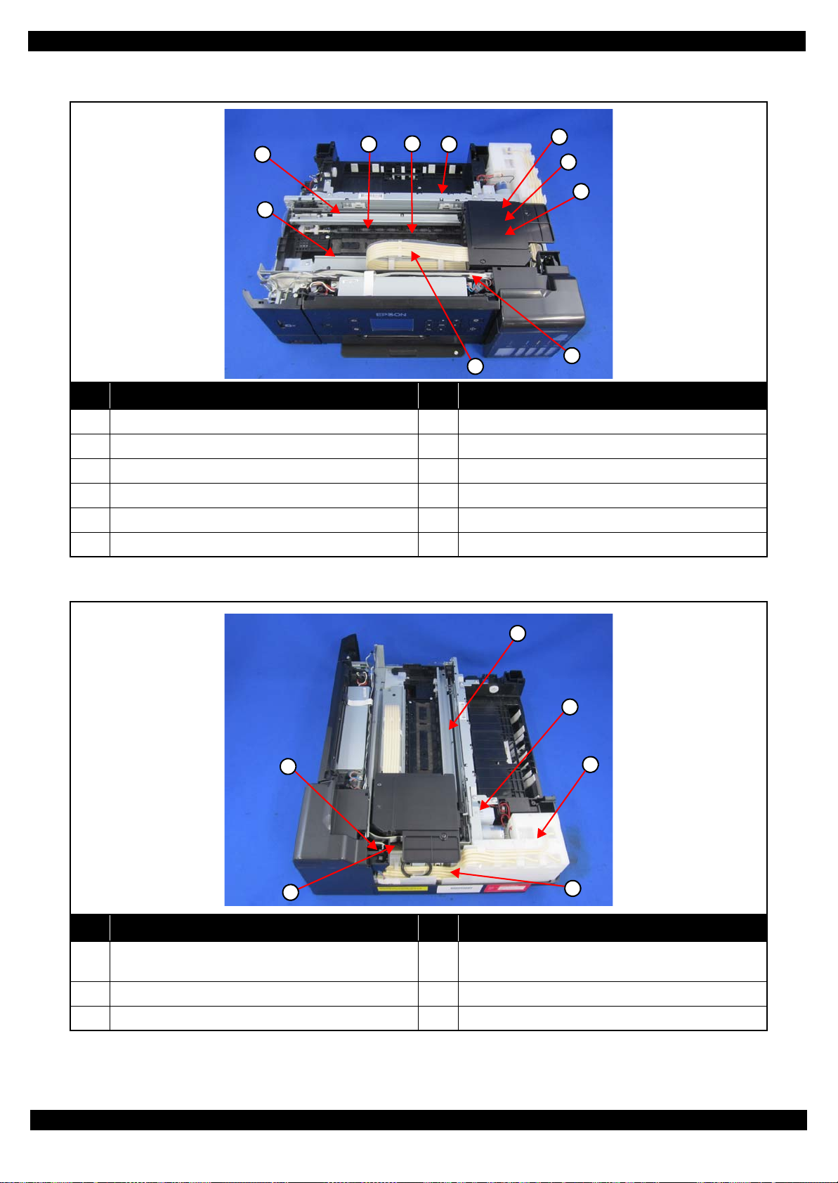
Epson ET-7700/L7160
2
3
6
7
4
5
8
9
10
1
4
1
2
3
6
5
Printer mechanism
No. Name No. Name
1 Star Wheel Holder Assy (p41) 7 Adapter Assy (p39)
2 CR Scale (p40) 8 Printhead (p39)
Revision D
3 Paper Guide Upper Assy (p40) 9 Head FFC Assy (p40)
4 Paper Guide Front Assy (p41) 10 Adapter Tube S/L (p45)
5 CR Guide Rail Assy (w/CR Unit) (p41) 11 Power Supply Board Assy (p45)
6 CR Cover (p39)
Figure 2-2. Printer Mechanism: Front
No. Name No. Name
Tank Cover Open Sensor (p44)
1
2 PE Sensor Assy (p43) 5 Air Chamber Tube Assy (p45)
3 Holder Cam Assy (p43) 6 Ink System Assy (p40)
Figure 2-3. Printer Mechanism: Right
Air Chamber Ink Supply 50 (p45)/Air Chamber Ink
4
Supply 100 (p45)
Disassembly/Reassembly Overview 23
Confidential
Page 24
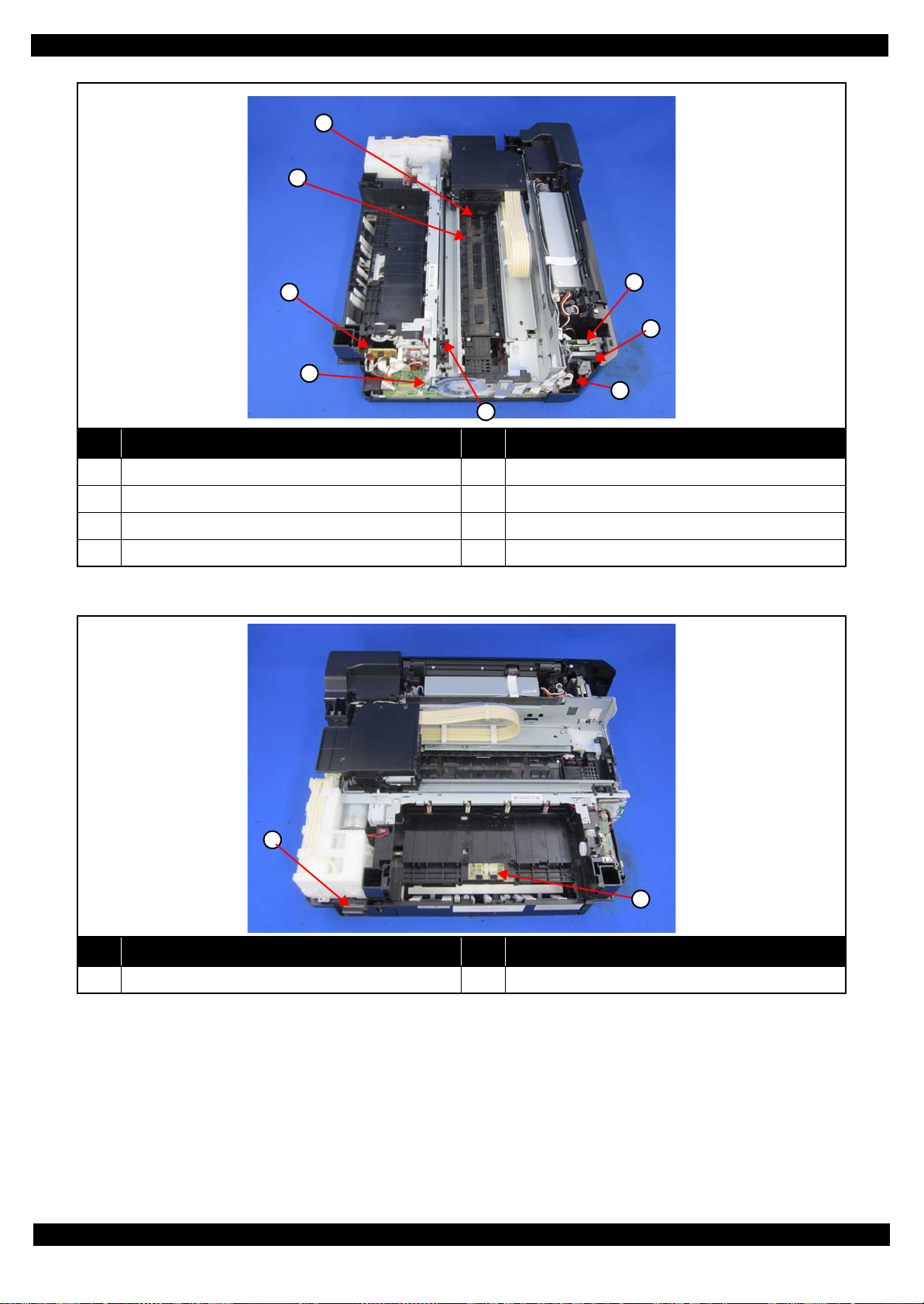
Epson ET-7700/L7160
2
3
5
7
1
6
4
8
1
2
No. Name No. Name
1 PW Sensor (p39) 5 APG Lever/ Gear’s (p41)
Revision D
2 Paper Guide Lower Porous Pad (p41) 6 Relay Board A (p40)
3 Relay Board B (p40) 7 Wireless LAN Module (p43)
4 PF Encoder Sensor (p40) 8 Card Slot Board (p43)
Figure 2-4. Printer Mechanism: Left
No. Name No. Name
1 Maintenance Box (p39) 2 Pick up Roller Assy (p39)
Figure 2-5. Printer Mechanism: Rear
Disassembly/Reassembly Overview 24
Confidential
Page 25

Epson ET-7700/L7160
2.1.4 Standard Operation Time for Servicing the Product
The following are the standard operation time for servicing the product. This standard operation time was
determined with the MTTR result measured using the prototype of ET-7700/L7160 which have the most
functions.
The underlined parts/units are supplied as After Service Parts.
Table 2-1. Standard Operation Time
Time (mm:ss)
Parts/Unit
Replacement
USB Cover 0:25 0:25
SC Lower Rear Left Housing
SC Document Cover Spacer 4:06 4:06
SC Lower Rear Right Housing
Document Cover Assy
Pick Up Roller Assy
CR Cover 0:42 0:42
Adapter Assy 1:20 1:20
Adapter
Adapter Pressing Plate
Rubber Seal
Print Head3
PW Sensor
Front Top Housing
SC Upper Housing Cover Cap
SCN Unit
SCN Upper Housing 4:41 4:41
CIS Module Unit 5:04 5:04
Spacer (x2) 4:57 4:57
CIS Module 4:57 4:57
SCN CR Unit 5:19 5:19
SCN Motor 7:35 0:58 8:33
CIS Holder Unit 7:35 7:35
SCN Housing Lower 5:19 5:19
Hinge 3:53 3:53
Hinge Assy 3:53 3:53
Hinge
Hinge Holder
Housing Upper Assy
Maintenance Box Assy Cover
Maintenance Box 0:24 0:24
Stacker Frame 1:20 1:20
Main Stacker
Tank Housing Assy 6:46 6:46
Front Lower Left Housing 7:57 7:57
Front Left Housing Assy
3:58 3:58
3:54 3:54
4:59 4:59
0:18 0:18
1:30 1:30
1:30 1:30
1:45 1:45
3:12 19:32 22:44
3:48 2:48 6:36
0:36 0:36
0:12 0:12
3:31 0:58 4:29
4:03 4:03
4:03 4:03
5:57 5:57
4:29 4:29
1:29 1:29
6:26 6:26
Adjustment/
inspection
Revision D
Total
Disassembly/Reassembly Overview 25
Confidential
Page 26

Epson ET-7700/L7160
Wireless Lan USB Module 6:54 6:54
Sub Board Assy
Card Slot Assy 6:16 6:16
Front Left Housing
PS Grounding Plate
Frame Base Left Assy
Front Upper Shield Plate & Grounding Plate 13:22 13:22
Main Board Assy
Front Lower Shield Plate 14:07 14:07
Back Lower Shield Plate 14:12 14:12
Left Frame Base
Paper Guide Frame Bank Assy
EMI Frame 9:24 9:24
CR Scale & Spring
CR Scale Hold & CR Spacer 6:23 6:23
PF Encoder Assy
PF Sensor 7:11 7:11
Parallelism Bush (L) 6:30 7:53 14:23
FFC Cover Frame 6:41 6:41
Sub Board Assy
Paper Guide Upper Assy
CR Encoder Sensor 7:12 7:12
Panel Unit
Panel Lower Housing 9:45 9:45
Panel Left Housing Assy 10:04 10:04
Panel Right Housing Assy 10:04 10:04
Panel Board Assy 11:08 11:08
Panel Upper Housing 11:08 11:08
Tank Cover Assy
Tube Lock
Photo Interrupter
Tank Cap Assy
Hinge Cap Assy 10:26 10:26
Tank Cap Housing 10:34 10:34
Tank Cap 10:34 10:34
Key Slot 10:34 10:34
Tank Upper Porous Pad
Right Frame Base Assy
Right Sub Frame Base 10:59 10:59
Air Chamber Tube S
Air Chamber Tube L
Parts/Unit
Table 2-1. Standard Operation Time
Replacement
6:56 6:56
8:13 8:13
6:42 6:42
EEPROM data copy OK
EEPROM data copy NG
EEPROM data copy OK
EEPROM data copy NG
11:46
14:02
14:12 14:12
13:04 13:04
6:28 6:28
6:38 6:38
6:25 6:25
6:39 11:56 18:35
6:28 6:28
6:06 6:06
6:12 6:12
7:07 7:07
10:20 10:20
10:27 10:27
14:29 14:29
17:04 17:04
16:57 16:57
Time (mm:ss)
Adjustment/
inspection
2:39
21:52
2:39
21:52
Revision D
Total
14:25
33:38
16:41
35:54
Disassembly/Reassembly Overview 26
Confidential
Page 27

Epson ET-7700/L7160
Air Chamber Tube Assy 19:26 19:26
Air Chamber Holder 21:22 21:22
Air Chamber Ink Supply 50
Air Chamber Ink Supply 100
Power Supply Board Assy
Ink Supply Tank 100
Tank Unit 50
Adapter Tube S/L
CSIC Cable Holder Assy 20:01 20:01
CSIC Connector
CSIC Cable Holder 20:10 20:10
Ink Eject CSIC Cable
Main Cassette Torsion Spring 23:31 23:31
Main Cassette Lock 23:44 23:44
Ink Eject Housing Leaf Spring 19:52 19:52
Right Frame Base 24:07 24:07
Ink System Assy
Ink System Lower Porous Pad
Panel Frame 13:56 13:56
FFC Holder 19:35 19:35
Head FFC
Sub Guide Tube Frame 6:43 6:43
Guide Tube 11:22 11:22
CR Driven Pulley Spring Holder 6:18 6:18
CR Driven Pulley & Pulley Holder 6:52 6:52
CR Guide Rail Assy. (w/ CR Unit)
Protection Cover 11:00 11:00
Parallelism Bush (R)
Front Frame 18:58 7:22 26:20
Star Wheel Holder Assy.
Front Paper Guide Assy
Paper Guide Lower Porous Pad
Paper Guide Lower Porous Pad E
Grounding Plate 22:10 22:10
Main Frame Assy 24:28 10:12 34:40
PE Sensor & Holder
CR Motor
Holder Cam Assy
Change Lever 24:24 24:24
PF Roller Assy. Fixture Plate 24:59 24:59
Gear Holding Plate 24:08 24:08
Drive Trans. Gears (Pickup, different 3pcs) 24:29 24:29
Parts/Unit
Table 2-1. Standard Operation Time
Replacement
21:32 21:32
21:32 21:32
21:31 3:02 24:33
20:06 20:06
19:57 19:57
20:24 20:24
20:10 20:10
20:52 20:52
13:49 13:49
13:52 13:52
21:14 21:14
6:52 11:12 18:04
18:21 7:53 26:14
21:47 6:03 27:50
23:21 14:24 37:45
23:28 00:16 23:44
23:25 00:16 23:41
25:27 1:06 26:33
25:54 1:06 26:33
26:43 0:22 26:16
Time (mm:ss)
Adjustment/
inspection
Revision D
Total
Disassembly/Reassembly Overview 27
Confidential
Page 28

Epson ET-7700/L7160
Main Frame Fixture Plate (x2) 24:00 24:00
Stacker Roller Assy Holding Plate 27:14 27:14
EJ Roller Assy 26:15 6:03 32:18
Frame Base Cover 25:57 25:57
PF Roller Assy. (w/ PF Scale) 26:57 6:44 33:41
Drive Trans. Gears (PF, different 2pcs) 31:59 31:59
PF Motor Assy. 33:47 0:19 34:06
Drive Trans. Shaft (Pickup) 30:49 30:49
Slide Lever 30:35 30:35
Pickup Roller Assy. Holding Lever & Spring 30:59 30:59
Frame Base 33:03 11:12 44:15
Duplex Unit 0:07 3:00 3:07
MSF Cover 0:44 0:44
MSF Frame Assy 1:04 3:00 4:04
1st Cassette Assy 0:06 1:29 1:35
Cassette Cover 0:28 0:28
1st Cassette 1:05 1:29 2:34
2nd Cassette 0:00 1:29 1:29
Parts/Unit
Table 2-1. Standard Operation Time
Replacement
Time (mm:ss)
Adjustment/
inspection
Revision D
Total
Disassembly/Reassembly Overview 28
Confidential
Page 29
Epson ET-7700/L7160
2.
EMI Frame
CR Guide
Rail Assy
3.
MSF Frame Assy
2. 2.
3.
2.
4.2.
2.
2.2 Common cautions when disassembling/reassembling the Product
This section describes common cautions when disassembling/reassembling the product.
Before disassembling/reassembling the printer including this product, be sure to read "Safety Precautions(p3)"
and this section.
Item Content Photo/Illustration
Revision D
When
handling
parts
1. When handling new parts for replacement, take care not to
contaminate or damage them.
2. When disassembling/reassembling the parts, take care not to damage
the FFCs/cables/Ink tube if there is a possibility of coming into
contact with them.
3. When reassembling the product, take care not to let components of the
unit come off.
When
reassembling
When
applying
When installing parts, take care not to damage them when securing them
by tightening screws.
Do not lubricate any part other than those specified. If grease is applied
on such a part, wipe it off completely. ---
grease
External
Confirm visually that there are no scratches, dirt, and gaps.
parts
Moving parts After reassembling, confirm that there are no abnormal noises and they
work smoothly.
Timing belts 1. Take care not to broke them.
2. Confirm that it is installed properly onto the transmissive sections of
the pinion gear/driven roller.
---
---
Motors Take care not to damage them. ---
Sensors 1. Take care not to touch the detector sections.
2. As for the encoder Sensor used with a circular scale, the photo sensor
section should be set over the encoded area of the circular scale.
3. Take care not to get injured by the sharp ends of the board terminal on
the back of the circuit boards when handling the sensors or the
peripheral parts.
Scales 1. Take care not to touch the encoded area.
2. Install it with the black triangular section up. (CR Scale only)
3. Wipe off alcohol before installing. (CR Scale only)
4. Confirm that they do not touch the photo sensors after installation.
Waste ink
pads
1. Take care not to stain your hands with the waste ink soaked in the ink
pads. If ink comes into contact with your hands, wash it off with water
immediately.
2. Take care not to stain the printer's parts with the waste ink soaked in
the ink pads. If ink comes into contact with the parts, wash it off.
(Especially, pay attention to Paper Guide Front/Lower Porous Pad)
Disassembly/Reassembly Common cautions when disassembling/reassembling the Product 29
Confidential
Page 30

Epson ET-7700/L7160
Holder Cam Assy
D/E Lever
Protrusion
Groove
FFC Cover Frame
2.
Item Content Photo/Illustration
FFCs 1. Be sure to insert them to their connectors on the boards as far as they
Gears When installing gears, pay attention to the following:
PF rollers Do not touch rollers for paper feeding when handling them.
will go without any loose connection such as a half-way or slant
connection.
2. Route them along their routing paths.
3. If the double-sided tape that secures the FFCs is not strong enough to
secure them, make sure to replace the tape and secure the FFCs
firmly.
• The gear section should not be damaged.
• No foreign material is attached.
• No grease is attached on any parts other than those specified.
Revision D
---
---
One Time
parts
Holder Cam
Assy
After removing One Time parts specified in this manual, do not reuse
them, but be sure to replace them with new ones.
Install the assy while aligning the protrusion on the D/E Lever with the
groove on the cam of the Holder Cam Assy.
Ink System 1. Take care not to stain your hands with ink.
2. When you connect the ink tube to another part, insert the ink tube up
to the root of the joint to prevent ink leakage and secure the tube with
the tube clamp.
3. If it's hard to insert the ink tube to the joint, apply CR06 to the
inserting part of the ink tube.
MAC
Address
Label
1. Take care not to stain or damage it.
2. When replacing the printer mechanism, attach the Main Board and the
part with the MAC address label to the new printer mechanism.
One Time icon:
---
Disassembly/Reassembly Common cautions when disassembling/reassembling the Product 30
Confidential
Page 31

Epson ET-7700/L7160
1st Cassette
2nd Cassette
Duplex Unit
10
11
2.3 Disassembly/Reassembly Procedures
2.3.1 Parts/units to be removed before disassembly and reassembly
In "2.3.5 Disassembly Flowchart (p38)", the procedures are indicated on the premise that some parts/units are
removed in advance. Make sure to remove the following parts/units before starting disassembly.
1st Cassette / 2nd Cassette
Revision D
Duplex Unit
Figure 2-6. Removing the 1st Cassette/2nd Cassette
Figure 2-7. Removing the Duplex Unit
Note *: See (p 43) for disassembling the components of the Duplex Unit.
Note *: See (p 43) for disassembling the components of the 1st Cassette.
Disassembly/Reassembly Disassembly/Reassembly Procedures 31
Confidential
Page 32

Epson ET-7700/L7160
Waste ink tube of Pump
Disconnect Adapter Tube
2.3.2 Required work before disassembling Adapter Assy
Ink supply part of Adapter Assy doesn't have valve structure, so that ink in Adapter Assy leaks in Carriage when
disassembling Adapter Assy from Carriage.
When disassembling Adapter Assy, flush ink in Adapter Assy by the following procedure to prevent ink leakage.
2.3.2.1 Procedure 1
1. Connect waste ink tube of Ink System (Pump) to any waste ink bottle.
Do not flush ink in Maintenance Box. If flushing ink in Maintenance Box, the actual ink amount in
Maintenance Box does not match with the ink counter of Maintenance Box and causes ink leakage.
2. Disconnect Adapter Tube from Adapter Assy.
When disconnecting Adapter Tube from Adapter Assy, place CR Unit above Cap Assy to catch leaked ink
from Adapter Assy.
Revision D
Figure 2-8. Ink Flushing
3. Flush ink in Adapter Assy. by "Ink flushing" function of Adjustment Program.
It takes about 4 minutes.
[Caution]
Fatal error, such as 000021, 000023 and 000031, occurs in case that “Ink flushing” is executed while 2nd
Cassette is not placed at the standard position or is not installed.
Install and place 2nd Cassette at the standard position when executing “Ink flushing”.
Disassembly/Reassembly Disassembly/Reassembly Procedures 32
Confidential
Page 33

Epson ET-7700/L7160
Remaining ink
Figure 2-9. Ink Flushing
4. Disassemble Adapter Assy. from Carriage after ink flushing is completed.
Revision D
5. Absorb remaining ink around Seal Rubber by cotton swab (the tip is thin) in reference to 4.1.1.2Cleaning the
seal rubber section of the printhead (p81) the seal rubber section of the printhead".
Figure 2-10. Ink Flushing
2.3.2.2 Procedure 2
1. Connect waste ink tube of Ink System (Pump) to a syringe (rough standard: tip = Φ3.2mm, capacity =
50mL).
2. Disconnect Adapter Tube from Adapter Assy.
When disconnecting Adapter Tube from Adapter Assy, place CR Unit above Cap Assy to catch leaked ink
from Adapter Assy.
Carriage needs to be at the capping position because ejecting ink in Adapter Assy.through Ink System (CAP).
Ink tube in Pump needs to be released from Pump roller (printer needs to be in normal condition after normal
power-off sequence).
Disassembly/Reassembly Disassembly/Reassembly Procedures 33
Confidential
Page 34

Epson ET-7700/L7160
Waste ink tube of Pump Disconnect Adapter Assy
Revision D
Figure 2-11. Ink Flushing
Disassembly/Reassembly Disassembly/Reassembly Procedures 34
Confidential
Page 35

Epson ET-7700/L7160
Remaining ink
Disconnect Adapter Tube
Connect syringe
3. Eject ink from Adapter Assy by the syringe slowly.
4. After disassembling Adapter Assy, absorb remaining ink around Seal Rubber by cotton swab (the tip is thin)
in reference to 4.1.1.2Cleaning the seal rubber section of the printhead (p81) the seal rubber section of the
print head.
Revision D
Figure 2-12. Ink Flushing
2.3.3 Required work before disassembling Ink tank
Eject ink from Ink tank before disassembling Ink tank accordingly.
1. Disconnect Adapter Tube from Adapter Assy.
When disconnecting Adapter Tube from Adapter Assy, place CR Unit above Cap Assy to catch leaked ink
from Adapter Assy.
2. Connect a syringe (rough standard: tip = Φ3.2mm, capacity = 50mL) to Adapter Tube.
Figure 2-13. Ink Flushing
Disassembly/Reassembly Disassembly/Reassembly Procedures 35
Confidential
Page 36

Epson ET-7700/L7160
Open Hinge Cap Assy
Eject ink
3. Open Tank Cover and Hinge Cap Assy.
4. Eject ink from Ink Tank by syringe.
5. Repeat procedure 1-4 for all Ink Tank.
Revision D
Figure 2-14. Ink Flushing
Disassembly/Reassembly Disassembly/Reassembly Procedures 36
Confidential
Page 37

Epson ET-7700/L7160
2.3.4 Printer Inspection Mode (Service Mode)
This section explains the Printer Inspection Mode (Service Mode) that printer functions without scanner unit.
1. Press OK button and Power button more than 3 seconds until the service mode entry screen (ID input screen)
is indicated.
2. Input ID by arrow button (UP/DOWN/RIGHT), then press OK button. ID : 49515
Revision D
3. When the menu screen of the service mode is indicated, select “1. Printer Inspection Mode” by pressing OK
button.
4. Enter Printer Inspection Mode by pressing START button.
Disassembly/Reassembly Disassembly/Reassembly Procedures 37
Confidential
Page 38

Epson ET-7700/L7160
USB Cover
1
4
(p22) (p43)
Main Frame Assy
---
---
(p21) (p27)
Paper Guide
Upper Assy (p29)
CR Timing Belt
FFC/ Cable *1
Shows necessary
procedures before
removing the following
parts.*
Black letters indicate a part/
unit not supplied as an ASP.
Item Description Reference
Parts/unit name
White-letter
Part/unit supplied as an ASP ---
Black-letter
Part/unit not supplied as an ASP ---
Icon
Indicates a practice or condition that could result in
injury or loss of life if not strictly observed.
Indicates the reference
page in blue-letter
Indicates a practice or condition that could result in
damage to, or destruction of equipment if not strictly
observed.
Indicates the reference
page in blue-letter
Indicates the parts that are inevitably broken in the
disassembling procedure, and should be replaced with
a new one for reassembly.
Indicates the reference
page in blue-letter
Indicates necessary check items in the disassembling/
assembling procedure.
Indicates the reference
page in blue-letter
Indicates supplementary explanation for disassembly
is given.
Indicates the reference
page in blue-letter
Indicates particular tasks to keep quality of the units
are required.
Indicates the reference
page in blue-letter
Indicates particular routing of cables is required.
Indicates the reference
page in blue-letter
Indicates particular adjustment(s) is/are required.
Chapter 3 " Adjustment
(p59)"
Indicates lubrication is required.
Chapter 4 " Maintenance
(p78)"
Indicates the number of screws securing the parts/
units.
---
Indicates the points secured with other than a screw
such as a hook, rib, dowel or the like.
---
White letters indicate a
part/unit supplied as an
ASP.
Shows the screw types and
the specified torque on the
“Screw type/torque list”.
Reference page
Shows removal/installation
as a unit/assy. is available.
The name enclosed in gray
indicate a part/unit that
must be removed on the
way to the target parts.
Note "*": The box with only part names means the removal of the parts. If the name of
FFC or a cable is shown, disconnect the FFC or cable from the connector.
Shows the procedure
number on the “FFC/
cable list”.
2.3.5 Disassembly Flowchart
This section describes procedures for disassembling the parts/units in a flowchart format. For some parts/units,
detailed procedures or precautions are provided (accordingly indicated by icons and cell's color). Refer to the
explanations in the example chart below and perform an appropriate disassembling and assembling procedure.
(See "2.4 Detailed Disassembly/Reassembly Procedure for each Part/Unit (p47) ".)
For routing cables, see "2.5 Routing FFCs/cables (p54)".
The example below shows how to see the charts on the following pages.
S4
Revision D
Disassembly/Reassembly Disassembly/Reassembly Procedures 38
Confidential
Page 39

Epson ET-7700/L7160 Revision D
S1
S2
S3
S4
S5
S6
S7
S8
S9
S10
S11
S12
S13
S14
S28
S24
S29
S13
S9
S1
S7
S11
2.3.3.1 Disassembly Flowchart (ET-7700/L7160)
START
USB Cover
S9
(p 47) (p 54)
SCN Upper
Housing Cover
Cap (p39)
Scanner Unit
S25
(p 54)
Hinge Left/Right
S11
---
Top Front Hous-
ing Assy (p39)
Maintenance
Box Cover (p39)
Hinge Assy (p39)
Housing Upper
S10
---
(p 40)
B
11
---
---
---
Top Front Hous-
ing Assy
1
1
1
(p 47)
CR Cover
2
---
---
Stacker Guide
Rail
---
3
---
Adapter Assy
1
1
(p 48)
Adapter
2
Rubber Seal
A
(p 44)
---
---
---
---
---
(p 47)
Printhead
2
4
---
(p 47) (p 59)
Hinge Assy
1
---
---
Hinge
1
---
---
---
C
(p 41)
H
(p 44)
PW Sensor
(p 48)
Hinge Holder
I
---
(p 55)
(p 46)
1
---
(p 59)
---
---
SCN Upper
Housing Cover
Cap
(p 47)
Adapter Plate
---
Tank Housing
Assy (p44)
Stacker Guide
---
Rail (p39)
1
Maintenance
Box Cover
---
---
---
Pick up Roller
Assy
(p 89)
USB Cover (p39)
---
1
SCN Upper
Housing Cover
Cap (p39)
Scanner Unit
(p39)
Stacker Frame
---
---
---
---
---
Main Stacker
---
---
---
Maintenance
Box
---
---
---
SCN Left Lower
Housing
---
2
---
Screw type/torque list
Symbol Screw Type Torque
C.B.P2-TITE SCREW 2.5x4 F/ZN-3C 1.5 ± 1 kgf·cm
SCN Right
Lower Housing
---
SCN Document
Cover Spacer
---
2
---
---
2
C.B.P-TITE P2 SCREW 3x8 F/ZN-3C 6 ± 1 kgf·cm
C.B.P-TITE P4 SCREW 3x10 F/ZN-3C 6 ± 1 kgf·cm
C.B.P-TITE SCREW 2.5x10 F/ZN-3C 6 ± 0.5 kgf·cm
C.B.P-TITE SCREW 2.5x6 F/ZN-3C 1.5 ± 1 kgf·cm
C.B.P-TITE SCREW 2.5x8 F/ZN-3C 6 ± 1 kgf·cm
C.B.P-TITE SCREW 2.5x8 F/ZN-3C 3 + 1 / -0 kgf·cm
C.B.P-TITE SCREW 2x6 F/ZN-3C 4 ± 1 kgf·cm
SCN Document
Cover Spacer
---
SCN Right
Lower Housing
(p39)
---
2
SCN Document
Cover Spacer
(p39)
SCN Document
Cover Assy
---
S15
---
2
S16
S17
S18
S19
S20
S21
S22
S23
S24
S25
S26
S27
C.B.P-TITE SCREW 3x10 F/ZB-3C 6 ± 1 kgf·cm
C.B.P-TITE SCREW 3x10 F/ZN-3C 6 ± 1 kgf·cm
C.B.P-TITE SCREW 3x12 F/ZB-3C 8 ± 1 kgf·cm
C.B.P-TITE SCREW 3x6 F/ZN-3C 4 ± 1 kgf·cm
C.B.P-TITE SCREW 3x8 F/ZN-3C 6 ± 1 kgf·cm
C.B.S-TITE P4 SCREW 3x6 F/ZN-3C 6 ± 1 kgf·cm
C.B.S-TITE SCREW 3x6 F/ZN-3C 1.5 ± 1 kgf·cm
C.B.S-TITE SCREW 3x6 F/ZN-3C 4 ± 1 kgf·cm
C.B.S-TITE SCREW 3x6 F/ZN-3C 6 ± 1 kgf·cm
C.B.S-TITE SCREW 3x6 F/ZN-3C 8 ± 1 kgf·cm
C.C.P-TITE SCREW 3x10 F/ZB-3C 6 ± 1 kgf·cm
C.P SCREW 3x4 F/ZN-3C 6 ± 1 kgf·cm
C.P SCREW 3x6 F/ZN-3C 6 ± 1 kgf·cm
C.P.F.B-TITE SCREW 1.7x5 F/ZN-3C 4 ± 1 kgf·cm
C.P.P-TITE SCREW 3x8 F/ZN-3C 4 ± 1 kgf·cm
C.B.P-TITE SCREW 3x14 F/ZB-3C 8 ± 1 kgf·cm
C.B.P-TITE SCREW 3x12 F/ZB-3C 8 ± 1 kgf·cm
C.B.S-TITE SCREW 3x5 F/ZN-3C 6 ± 1 kgf·cm
C.B.S-TITE SCREW 3x10 F/ZN-3C 6 ± 1 kgf·cm
C.B.S-TITE SCREW 3x8 F/ZN-3C 8 ± 1 kgf·cm
Flowchart 2-1. Disassembly/Reassembly Flowchart (1)
Disassembly/Reassembly Disassembly/Reassembly Procedures 39
Confidential
Page 40

Epson ET-7700/L7160 Revision D
S9
S10
S10
S22
S2
S10
S1
S2
S3
S4
S5
S6
S7
S8
S9
S10
S11
S12
S13
S14
S28
S28
S10
S18
(p 39)
B
Left Bottom
Housing
S10
---
Left Bottom
Housing Assy
S17
(p 48) (p 56)
Panel Unit
(p 52) (p 56) (p 59)
Left Bottom
Housing (p40)
Left Bottom
Housing Assy
(p40)
CR Cover (p39)
Adapter Assy
(p39)
Rubber Seal
(p39)
Printhead (p39)
Tank Housing
Assy (p44)
Tank Cover Assy
(p44)
Panel Assy (p43)
Power Supply
Board Assy (p45)
(p40) (p40) (p40)
Panel Frame
(p40)
Tank Housing
Assy (p44)
Tank Cap Assy
(p44)
2
1
EMI Frame
---
2
---
2
---
(p 43)
4
4
---
(p 43)
5
Torsion Spring 13.13
CR Scale
Relay Board A
---
(p40) (p40) (p40)
Left Frame Base
Assy
(w/Main Board)
(p 55) (p 59)
(p 41)
D
FFC Holder
---
Head FFC Assy
(p 56)
(p 48)
1
---
6
1
---
---
---
---
PF Encoder
Sensor
CR Driven Pul-
ley & Pulley
Holder
---
2
(p 48)
---
2
PF Encoder
Sensor Holder
Assy
S18
(p 55)
2
1
1
S8
(p 55)
1
Parallelism Bush
(L)
FFC Cover
Frame
S17
(p 48)
---
2
Relay Board B
2
S10
(p 55)
---
Tank Housing
Assy (p44)
Tank Cap Assy
(p44)
Panel Assy (p43)
Power Supply
Board Assy (p45)
(p40) (p40) (p40)
1
(p40) (p40) (p40)
1
(p 55)
Panel Frame
3
---
---
Screw type/torque list
CR Cover (p39)
CR Encoder
Sensor *
2
---
Symbol Screw Type Torque
C.B.P2-TITE SCREW 2.5x4 F/ZN-3C 1.5 ± 1 kgf·cm
C.B.P-TITE P2 SCREW 3x8 F/ZN-3C 6 ± 1 kgf·cm
C.B.P-TITE P4 SCREW 3x10 F/ZN-3C 6 ± 1 kgf·cm
2
---
S15
S16
S17
S18
S19
S20
S21
S22
S23
S24
S25
S26
S27
C.B.P-TITE SCREW 2.5x10 F/ZN-3C 6 ± 0.5 kgf·cm
C.B.P-TITE SCREW 2.5x6 F/ZN-3C 1.5 ± 1 kgf·cm
C.B.P-TITE SCREW 2.5x8 F/ZN-3C 6 ± 1 kgf·cm
C.B.P-TITE SCREW 2.5x8 F/ZN-3C 3 + 1 / -0 kgf·cm
C.B.P-TITE SCREW 2x6 F/ZN-3C 4 ± 1 kgf·cm
C.B.P-TITE SCREW 3x10 F/ZB-3C 6 ± 1 kgf·cm
C.B.P-TITE SCREW 3x10 F/ZN-3C 6 ± 1 kgf·cm
C.B.P-TITE SCREW 3x12 F/ZB-3C 8 ± 1 kgf·cm
C.B.P-TITE SCREW 3x6 F/ZN-3C 4 ± 1 kgf·cm
C.B.P-TITE SCREW 3x8 F/ZN-3C 6 ± 1 kgf·cm
C.B.S-TITE P4 SCREW 3x6 F/ZN-3C 6 ± 1 kgf·cm
C.B.S-TITE SCREW 3x6 F/ZN-3C 1.5 ± 1 kgf·cm
C.B.S-TITE SCREW 3x6 F/ZN-3C 4 ± 1 kgf·cm
C.B.S-TITE SCREW 3x6 F/ZN-3C 6 ± 1 kgf·cm
C.B.S-TITE SCREW 3x6 F/ZN-3C 8 ± 1 kgf·cm
C.C.P-TITE SCREW 3x10 F/ZB-3C 6 ± 1 kgf·cm
C.P SCREW 3x4 F/ZN-3C 6 ± 1 kgf·cm
C.P SCREW 3x6 F/ZN-3C 6 ± 1 kgf·cm
C.P.F.B-TITE SCREW 1.7x5 F/ZN-3C 4 ± 1 kgf·cm
C.P.P-TITE SCREW 3x8 F/ZN-3C 4 ± 1 kgf·cm
C.B.P-TITE SCREW 3x14 F/ZB-3C 8 ± 1 kgf·cm
C.B.P-TITE SCREW 3x12 F/ZB-3C 8 ± 1 kgf·cm
C.B.S-TITE SCREW 3x5 F/ZN-3C 6 ± 1 kgf·cm
C.B.S-TITE SCREW 3x10 F/ZN-3C 6 ± 1 kgf·cm
C.B.S-TITE SCREW 3x8 F/ZN-3C 8 ± 1 kgf·cm
6
(p 43)
Tank Housing
Assy (p44)
Tank Cap Assy
(p44)
Power Supply
Board Assy (p45)
Tube Lock (p44)
EMI Frame
(p40)
Right Frame
Base Assy
S10
(p 49)
(p 54)
Ink System Assy
S10
(p 49)
Porous Pad for
Ink System Assy
---
5
1
(p 59)
2
---
---
---
Paper Guide
Upper Assy
---
---
(p 49) (p 59)
Flowchart 2-2. Disassembly/Reassembly Flowchart (2)
Disassembly/Reassembly Disassembly/Reassembly Procedures 40
Confidential
Page 41

Epson ET-7700/L7160 Revision D
S18
S14
S2
S10
S10
S3
S18
S10
S1
S2
S3
S4
S5
S6
S7
S8
S9
S10
S11
S12
S13
S14
S28
C
CR Scale (p40)
CR Scale Holder
S18
---
Extension spring
CR Driven
Pulley Assy
(p 87)
FFC Cover
Frame (p40)
CR Driven Pul-
ley & Pulley
Holder (p40)
CR Guide Rail
Assy (w/CR Unit)
S14
(p 49) (p 56)
(p 59) (p 88)
Protection Cover
S18
---
E
(p 39)
(p 41)
D
(p 40)
Left Bottom
Housing Assy
(p40)
2nd Cassette
Sensor Holder
1
S13
1
---
Paper Guide
Rear ASF Assy
(p 55)
---
4
S10
(p 55)
---
Sub Guide Tube
Frame (p46)
Guide Tube
(p46)
---
4
Main Cassette
Torsion Spring
---
---
---
Star Wheel
Holder Assy
---
4
---
Tank Housing
Assy (p44)
Tank Cap Assy
(p44)
Power Supply
1
---
Board Assy (p45)
Tube Lock (p44)
EMI Frame
(p40)
Right Frame
Base Assy (p40)
---
Paper Guide
Front Assy
S19
(p 51) (p 56)
(p 59) (p 86)
---
4
---
Paper Guide
Parallel
Adjustment
Bush Right
Lower Poro us
Pad B
1
(p 42)
1
(p 59)
F
(p 50)
E
Tank Cover Assy
(p44)
Tank Cap Assy
(p44)
Power Supply
Board Assy (p45)
Tube Lock (p44)
EMI Frame
(p40)
Left Frame Base
Assy (w/Main
Board) (p40)
Parallel Adjust-
ment Bush Right
(p41)
Front Frame
S10
(p 50) (p 88)
Guide Tube
(p46)Ink System
Assy (p40)
Paper Guide
Upper Assy (p40)
PF Encoder Sen-
sor Holder Assy
(p40)
Grounding Plate
S26
---
---
---
(p 41)
3
---
1
---
Paper Guide
Lower Porous
Pad
(p 50)
Main Frame
Assy
(p 51) (p 57)
(p 59) (p 87)
8
(p 43)
---
---
6
1
Paper Guide
Lower Porous
Pad E
(p 50)
Left Frame Base
Assy (w/Main
Board) (p40)
Relay Board B
(p40)
Relay Board B
(p40)
PF Roller
Fixture Plate
S27
---
Gear Holding
Plate
(p 53) (p 88)
APG Lever/
Gear’s
(p 53)
Drive
Transmission
Gear’s Left
(p 53) (p 87)
---
---
---
---
1
---
Screw type/torque list
Symbol Screw Type Torque
---
---
---
2
S15
S16
S17
S18
S19
S20
S21
S22
S23
S24
S25
S26
S27
Gear Fixture
Plate
S13
(p 51)
One Way Clutch
Gear
1
---
Main Frame Fix-
ture Plate
---
---
---
---
(p 51)
C.B.P2-TITE SCREW 2.5x4 F/ZN-3C 1.5 ± 1 kgf·cm
C.B.P-TITE P2 SCREW 3x8 F/ZN-3C 6 ± 1 kgf·cm
C.B.P-TITE P4 SCREW 3x10 F/ZN-3C 6 ± 1 kgf·cm
C.B.P-TITE SCREW 2.5x10 F/ZN-3C 6 ± 0.5 kgf·cm
C.B.P-TITE SCREW 2.5x6 F/ZN-3C 1.5 ± 1 kgf·cm
C.B.P-TITE SCREW 2.5x8 F/ZN-3C 6 ± 1 kgf·cm
C.B.P-TITE SCREW 2.5x8 F/ZN-3C 3 + 1 / -0 kgf·cm
C.B.P-TITE SCREW 2x6 F/ZN-3C 4 ± 1 kgf·cm
C.B.P-TITE SCREW 3x10 F/ZB-3C 6 ± 1 kgf·cm
C.B.P-TITE SCREW 3x10 F/ZN-3C 6 ± 1 kgf·cm
C.B.P-TITE SCREW 3x12 F/ZB-3C 8 ± 1 kgf·cm
C.B.P-TITE SCREW 3x6 F/ZN-3C 4 ± 1 kgf·cm
C.B.P-TITE SCREW 3x8 F/ZN-3C 6 ± 1 kgf·cm
C.B.S-TITE P4 SCREW 3x6 F/ZN-3C 6 ± 1 kgf·cm
C.B.S-TITE SCREW 3x6 F/ZN-3C 1.5 ± 1 kgf·cm
C.B.S-TITE SCREW 3x6 F/ZN-3C 4 ± 1 kgf·cm
C.B.S-TITE SCREW 3x6 F/ZN-3C 6 ± 1 kgf·cm
C.B.S-TITE SCREW 3x6 F/ZN-3C 8 ± 1 kgf·cm
C.C.P-TITE SCREW 3x10 F/ZB-3C 6 ± 1 kgf·cm
C.P SCREW 3x4 F/ZN-3C 6 ± 1 kgf·cm
C.P SCREW 3x6 F/ZN-3C 6 ± 1 kgf·cm
C.P.F.B-TITE SCREW 1.7x5 F/ZN-3C 4 ± 1 kgf·cm
C.P.P-TITE SCREW 3x8 F/ZN-3C 4 ± 1 kgf·cm
C.B.P-TITE SCREW 3x14 F/ZB-3C 8 ± 1 kgf·cm
C.B.P-TITE SCREW 3x12 F/ZB-3C 8 ± 1 kgf·cm
C.B.S-TITE SCREW 3x5 F/ZN-3C 6 ± 1 kgf·cm
C.B.S-TITE SCREW 3x10 F/ZN-3C 6 ± 1 kgf·cm
C.B.S-TITE SCREW 3x8 F/ZN-3C 8 ± 1 kgf·cm
Flowchart 2-3. Disassembly/Reassembly Flowchart (3)
Disassembly/Reassembly Disassembly/Reassembly Procedures 41
Confidential
Page 42

Epson ET-7700/L7160 Revision D
S10
S1
S2
S3
S4
S5
S6
S7
S8
S9
S10
S11
S12
S13
S14
S28
(p 41)
F
Frame Base
Front Cover
---
PF Roller Assy
(p 59)
(p 89)
Paper Guide
Rear ASF Assy
(p41)
Pick up Roller
Assy (p39)
Gear Fixture
Plate (p41)
One Way Clutch
Gear (p41)
2nd Cassette
Sensor Holder
(p41)
Drive Transmission Gear’s Left
(p41)
3
---
EJ Roller Assy
---
1
(p 50)
(p 59)
(p 89)
Stacker Guide
Rail (p39)
Main Stacker
(p39)
Stacker Frame
(p39)
Pick up Driven
Shaft
---
---
---
Stacker Roller
Assy Holding
---
Plate
---
--2
(p 89)
Slide Lever
---
Screw type/torque list
---
1
Symbol Screw Type Torque
C.B.P2-TITE SCREW 2.5x4 F/ZN-3C 1.5 ± 1 kgf·cm
C.B.P-TITE P2 SCREW 3x8 F/ZN-3C 6 ± 1 kgf·cm
C.B.P-TITE P4 SCREW 3x10 F/ZN-3C 6 ± 1 kgf·cm
C.B.P-TITE SCREW 2.5x10 F/ZN-3C 6 ± 0.5 kgf·cm
C.B.P-TITE SCREW 2.5x6 F/ZN-3C 1.5 ± 1 kgf·cm
C.B.P-TITE SCREW 2.5x8 F/ZN-3C 6 ± 1 kgf·cm
C.B.P-TITE SCREW 2.5x8 F/ZN-3C 3 + 1 / -0 kgf·cm
C.B.P-TITE SCREW 2x6 F/ZN-3C 4 ± 1 kgf·cm
C.B.P-TITE SCREW 3x10 F/ZB-3C 6 ± 1 kgf·cm
C.B.P-TITE SCREW 3x10 F/ZN-3C 6 ± 1 kgf·cm
C.B.P-TITE SCREW 3x12 F/ZB-3C 8 ± 1 kgf·cm
C.B.P-TITE SCREW 3x6 F/ZN-3C 4 ± 1 kgf·cm
C.B.P-TITE SCREW 3x8 F/ZN-3C 6 ± 1 kgf·cm
C.B.S-TITE P4 SCREW 3x6 F/ZN-3C 6 ± 1 kgf·cm
C.B.S-TITE SCREW 3x6 F/ZN-3C 1.5 ± 1 kgf·cm
C.B.S-TITE SCREW 3x6 F/ZN-3C 4 ± 1 kgf·cm
C.B.S-TITE SCREW 3x6 F/ZN-3C 6 ± 1 kgf·cm
C.B.S-TITE SCREW 3x6 F/ZN-3C 8 ± 1 kgf·cm
C.C.P-TITE SCREW 3x10 F/ZB-3C 6 ± 1 kgf·cm
C.P SCREW 3x4 F/ZN-3C 6 ± 1 kgf·cm
C.P SCREW 3x6 F/ZN-3C 6 ± 1 kgf·cm
C.P.F.B-TITE SCREW 1.7x5 F/ZN-3C 4 ± 1 kgf·cm
C.P.P-TITE SCREW 3x8 F/ZN-3C 4 ± 1 kgf·cm
C.B.P-TITE SCREW 3x14 F/ZB-3C 8 ± 1 kgf·cm
C.B.P-TITE SCREW 3x12 F/ZB-3C 8 ± 1 kgf·cm
C.B.S-TITE SCREW 3x5 F/ZN-3C 6 ± 1 kgf·cm
C.B.S-TITE SCREW 3x10 F/ZN-3C 6 ± 1 kgf·cm
Left Frame Base
Assy (w/Main
Board) (p40)
EJ Roller Assy
(p42)
Combination
Gear 17.03.10.2/
Spur Gear 49.32
---
PF Motor Assy
(p 59)
Pick up Assy
Holder Lever
---
1
---
Gear Fixture
---
---
3
---
Plate (p41)
One Way Clutch
Gear (p41)
Pick up Driven
Shaft (p42)
Porous Pad
Stopper
Paper Guide
Lower
PF Motor Assy
(p42)
Frame Base
(p 59) (p 86)
S15
S16
S17
S18
S19
S20
S21
S22
S23
---
---
S24
S25
S26
S27
C.B.S-TITE SCREW 3x8 F/ZN-3C 8 ± 1 kgf·cm
Flowchart 2-4. Disassembly/Reassembly Flowchart (4)
Disassembly/Reassembly Disassembly/Reassembly Procedures 42
Confidential
Page 43

Epson ET-7700/L7160 Revision D
S17
S20
S23
S4
S1
S2
S3
S4
S5
S6
S7
S8
S9
S10
S11
S12
S13
S14
S28
S19
(p 40)
4
Wireless LAN
Module
S17
---
Relay Board A
(p40)
Card Slot Board
---
Front Left Hous-
ing Assy
---
Sub Board Assy
---
(p 40)
5
(p 40)
6
Panel FFC
Panel Assy
4
2
---
(p 52)
(p 56)
---
(p 59)
Panel Lower
Housing
7
3
---
Panel Left Hinge
Assy (p43)
Panel Right
Hinge Assy (p43)
Panel Left Hinge
Assy
---
Panel Right
Hinge Assy
1
1
1
1
---
1
(p 41)
8
10
---
Panel Board
Panel Upper
Housing
(p 43)
Assy
---
---
Main Board
Shield Plate
Upper/
3
2
Grounding Plate
S10 S21
(p 50)
5
---
Main Board Assy
3
2
S10
(p 59)
Main Board
Shield Plate
2
---
Screw type/torque list
Front Lower
Symbol Screw Type Torque
1
C.B.P2-TITE SCREW 2.5x4 F/ZN-3C 1.5 ± 1 kgf·cm
PE Sensor Assy
1
---
S15
---
---
(p 59)
CR Motor
2
---
(p 59)
(p 43)
1
11
---
1st Cassette
---
---
(p 59)
Cassette Cover
1
---
---
Holder Cam
Assy
---
Change Lever
---
Main Cassette
---
Duplex Unit
1
2
(p 59)
---
---
---
Main Board
Shield Plate
Back Lower
---
---
MSF Cover
2
---
2
S19
---
2
---
---
MSF Frame Assy
S13
(p 59)
---
4
---
Left Frame Base
---
---
---
S15
S16
S17
S18
S19
S20
S21
S22
S23
S24
S25
S26
S27
--C.B.P-TITE P2 SCREW 3x8 F/ZN-3C 6 ± 1 kgf·cm
C.B.P-TITE P4 SCREW 3x10 F/ZN-3C 6 ± 1 kgf·cm
C.B.P-TITE SCREW 2.5x10 F/ZN-3C 6 ± 0.5 kgf·cm
C.B.P-TITE SCREW 2.5x6 F/ZN-3C 1.5 ± 1 kgf·cm
C.B.P-TITE SCREW 2.5x8 F/ZN-3C 6 ± 1 kgf·cm
C.B.P-TITE SCREW 2.5x8 F/ZN-3C 3 + 1 / -0 kgf·cm
C.B.P-TITE SCREW 2x6 F/ZN-3C 4 ± 1 kgf·cm
C.B.P-TITE SCREW 3x10 F/ZB-3C 6 ± 1 kgf·cm
C.B.P-TITE SCREW 3x10 F/ZN-3C 6 ± 1 kgf·cm
C.B.P-TITE SCREW 3x12 F/ZB-3C 8 ± 1 kgf·cm
C.B.P-TITE SCREW 3x6 F/ZN-3C 4 ± 1 kgf·cm
C.B.P-TITE SCREW 3x8 F/ZN-3C 6 ± 1 kgf·cm
C.B.S-TITE P4 SCREW 3x6 F/ZN-3C 6 ± 1 kgf·cm
C.B.S-TITE SCREW 3x6 F/ZN-3C 1.5 ± 1 kgf·cm
C.B.S-TITE SCREW 3x6 F/ZN-3C 4 ± 1 kgf·cm
C.B.S-TITE SCREW 3x6 F/ZN-3C 6 ± 1 kgf·cm
C.B.S-TITE SCREW 3x6 F/ZN-3C 8 ± 1 kgf·cm
C.C.P-TITE SCREW 3x10 F/ZB-3C 6 ± 1 kgf·cm
C.P SCREW 3x4 F/ZN-3C 6 ± 1 kgf·cm
C.P SCREW 3x6 F/ZN-3C 6 ± 1 kgf·cm
C.P.F.B-TITE SCREW 1.7x5 F/ZN-3C 4 ± 1 kgf·cm
C.P.P-TITE SCREW 3x8 F/ZN-3C 4 ± 1 kgf·cm
C.B.P-TITE SCREW 3x14 F/ZB-3C 8 ± 1 kgf·cm
C.B.P-TITE SCREW 3x12 F/ZB-3C 8 ± 1 kgf·cm
C.B.S-TITE SCREW 3x5 F/ZN-3C 6 ± 1 kgf·cm
C.B.S-TITE SCREW 3x10 F/ZN-3C 6 ± 1 kgf·cm
C.B.S-TITE SCREW 3x8 F/ZN-3C 8 ± 1 kgf·cm
Flowchart 2-5. Disassembly/Reassembly Flowchart (6)
Disassembly/Reassembly Disassembly/Reassembly Procedures 43
Confidential
Page 44

Epson ET-7700/L7160 Revision D
S29
S1
S2
S3
S4
S5
S6
S7
S8
S9
S10
S11
S12
S13
S14
S30
S9
S9
S10
A
Scanner Housing
Upper Assy
S10
---
CIS Module Unit
---
FFC/Cable* 8
Scanner Car-
riage Unit
(p 90) (p 91) (p 91)
Scanner Hous-
ing Lower
(p 90)
(p 39)
---
---
---
---
---
---
(p 39)
H
Tank Cover Assy
4
2
---
---
---
Tank Housing
Assy
3
1
---
Spacer
CIS Module
Tube Lock
---
Tank Cover
Open Sensor
S9
(p 58)
---
---
---
---
Screw type/torque list
---
Scanner Motor
(p 54)
CIS Holder Unit
---
--4
---
2
---
---
---
---
---
Tank Cover
Open Sensor
(p44)
Symbol Screw Type Torque
C.B.P2-TITE SCREW 2.5x4 F/ZN-3C 1.5 ± 1 kgf·cm
C.B.P-TITE P2 SCREW 3x8 F/ZN-3C 6 ± 1 kgf·cm
Tank Cap Assy
S10
S9
---
Power Supply
Board Assy (p45)
Tube Lock (p44)
EMI Frame
(p40)
Tank Upper
Porous Pad (p44)
Right Frame
Base Assy
(p 49)
J
(p 45)
Hinge Cap Assy
4
---
---
---
---
Tank Cap Hous-
ing
---
Tank Upper
Porous Pad
(p 52)
---
---
Key Slot
---
---
---
---
Tank Cap
---
---
---
FFC/cable list
No. FFC/Cable
Remove the double-sided tape(x1) and release the Scanner
8
FFC routing to the Scanner Carriage Unit.
---
S15
S16
S17
S18
---
---
S19
S20
S21
S22
S23
S24
S25
S26
S27
S28
S29
C.B.P-TITE P4 SCREW 3x10 F/ZN-3C 6 ± 1 kgf·cm
C.B.P-TITE SCREW 2.5x10 F/ZN-3C 6 ± 0.5 kgf·cm
C.B.P-TITE SCREW 2.5x6 F/ZN-3C 1.5 ± 1 kgf·cm
C.B.P-TITE SCREW 2.5x8 F/ZN-3C 6 ± 1 kgf·cm
C.B.P-TITE SCREW 2.5x8 F/ZN-3C 3 + 1 / -0 kgf·cm
C.B.P-TITE SCREW 2x6 F/ZN-3C 4 ± 1 kgf·cm
C.B.P-TITE SCREW 3x10 F/ZB-3C 6 ± 1 kgf·cm
C.B.P-TITE SCREW 3x10 F/ZN-3C 6 ± 1 kgf·cm
C.B.P-TITE SCREW 3x12 F/ZB-3C 8 ± 1 kgf·cm
C.B.P-TITE SCREW 3x6 F/ZN-3C 4 ± 1 kgf·cm
C.B.P-TITE SCREW 3x8 F/ZN-3C 6 ± 1 kgf·cm
C.B.S-TITE P4 SCREW 3x6 F/ZN-3C 6 ± 1 kgf·cm
C.B.S-TITE SCREW 3x6 F/ZN-3C 1.5 ± 1 kgf·cm
C.B.S-TITE SCREW 3x6 F/ZN-3C 4 ± 1 kgf·cm
C.B.S-TITE SCREW 3x6 F/ZN-3C 6 ± 1 kgf·cm
C.B.S-TITE SCREW 3x6 F/ZN-3C 8 ± 1 kgf·cm
C.C.P-TITE SCREW 3x10 F/ZB-3C 6 ± 1 kgf·cm
C.P SCREW 3x4 F/ZN-3C 6 ± 1 kgf·cm
C.P SCREW 3x6 F/ZN-3C 6 ± 1 kgf·cm
C.P.F.B-TITE SCREW 1.7x5 F/ZN-3C 4 ± 1 kgf·cm
C.P.P-TITE SCREW 3x8 F/ZN-3C 4 ± 1 kgf·cm
C.B.P-TITE SCREW 3x14 F/ZB-3C 8 ± 1 kgf·cm
C.B.P-TITE SCREW 3x12 F/ZB-3C 8 ± 1 kgf·cm
C.B.S-TITE SCREW 3x5 F/ZN-3C 6 ± 1 kgf·cm
C.B.S-TITE SCREW 3x10 F/ZN-3C 6 ± 1 kgf·cm
C.C.P-TITE SCREW 3x12 F/ZN-3C 6 ± 1 kgf·cm
C.B.P-TITE SCREW 3x8 F/ZN-3C 5 ± 1 kgf·cm
C.B.S-TITE SCREW 3x8 F/ZN-3C 8 ± 1 kgf·cm
Flowchart 2-6. Disassembly/Reassembly Flowchart (11)
Disassembly/Reassembly Disassembly/Reassembly Procedures 44
Confidential
Page 45

Epson ET-7700/L7160 Revision D
S1
S2
S3
S4
S5
S6
S7
S8
S9
S10
S11
S12
S13
S14
S30
S13
S10
S10
S13
S10
S13
S13
S10
(p 44)
J
Right Sub Frame
Base
---
Air Chamber
Tube Assy
---
Air Chamber
Tube S (p45)
Air Chamber
Tube L (p45)
Ink Supply T ank
100
(p 52)
PS Grounding
Plate
---
---
---
---
---
Tank Unit 50
1
1
(p 52)
1
1
Adapter Tube S/
L
---
---
---
CSIC Cable
Air Chamber
Tube S
Air Chamber
Tube L
---
---
Holder
---
---
(p 52)
---
(p 52)
---
---
CSIC Cable
Holder Assy
---
CSIC Connector
---
Main Cassette
Torsion Spring
2
2
---
Main Cassette
Lock
---
---
---
---
---
---
---
Ink Eject Housing Leaf Spring
---
1
---
Screw type/torque list
Symbol Screw Type Torque
Ink Eject CSIC
4
Air Chamber
Holder
2
S10
---
Air Chamber
Ink Supply 50
---
2
Tank Unit 50
Air Chamber
Ink Supply 100
---
---
---
---
---
(p45)
Adapter Tube S/
L (p45)
Ink Eject CSIC
Cable (p45)
Power Supply
Board Assy
(p 58)
Right Frame
Base
4
---
Ink Eject CSIC
Cable (p45)
Main Cassette
Torsion Spring
(p45)
Main Cassette
Lock (p45)
Ink Eject
Housing Leaf
Spring (p45)
---
2
---
---
Cable
---
---
---
S15
S16
S17
S18
S19
S20
S21
S22
S23
S24
S25
S26
S27
S28
S29
C.B.P2-TITE SCREW 2.5x4 F/ZN-3C 1.5 ± 1 kgf·cm
C.B.P-TITE P2 SCREW 3x8 F/ZN-3C 6 ± 1 kgf·cm
C.B.P-TITE P4 SCREW 3x10 F/ZN-3C 6 ± 1 kgf·cm
C.B.P-TITE SCREW 2.5x10 F/ZN-3C 6 ± 0.5 kgf·cm
C.B.P-TITE SCREW 2.5x6 F/ZN-3C 1.5 ± 1 kgf·cm
C.B.P-TITE SCREW 2.5x8 F/ZN-3C 6 ± 1 kgf·cm
C.B.P-TITE SCREW 2.5x8 F/ZN-3C 3 + 1 / -0 kgf·cm
C.B.P-TITE SCREW 2x6 F/ZN-3C 4 ± 1 kgf·cm
C.B.P-TITE SCREW 3x10 F/ZB-3C 6 ± 1 kgf·cm
C.B.P-TITE SCREW 3x10 F/ZN-3C 6 ± 1 kgf·cm
C.B.P-TITE SCREW 3x12 F/ZB-3C 8 ± 1 kgf·cm
C.B.P-TITE SCREW 3x6 F/ZN-3C 4 ± 1 kgf·cm
C.B.P-TITE SCREW 3x8 F/ZN-3C 6 ± 1 kgf·cm
C.B.S-TITE P4 SCREW 3x6 F/ZN-3C 6 ± 1 kgf·cm
C.B.S-TITE SCREW 3x6 F/ZN-3C 1.5 ± 1 kgf·cm
C.B.S-TITE SCREW 3x6 F/ZN-3C 4 ± 1 kgf·cm
C.B.S-TITE SCREW 3x6 F/ZN-3C 6 ± 1 kgf·cm
C.B.S-TITE SCREW 3x6 F/ZN-3C 8 ± 1 kgf·cm
C.C.P-TITE SCREW 3x10 F/ZB-3C 6 ± 1 kgf·cm
C.P SCREW 3x4 F/ZN-3C 6 ± 1 kgf·cm
C.P SCREW 3x6 F/ZN-3C 6 ± 1 kgf·cm
C.P.F.B-TITE SCREW 1.7x5 F/ZN-3C 4 ± 1 kgf·cm
C.P.P-TITE SCREW 3x8 F/ZN-3C 4 ± 1 kgf·cm
C.B.P-TITE SCREW 3x14 F/ZB-3C 8 ± 1 kgf·cm
C.B.P-TITE SCREW 3x12 F/ZB-3C 8 ± 1 kgf·cm
C.B.S-TITE SCREW 3x5 F/ZN-3C 6 ± 1 kgf·cm
C.B.S-TITE SCREW 3x10 F/ZN-3C 6 ± 1 kgf·cm
C.C.P-TITE SCREW 3x12 F/ZN-3C 6 ± 1 kgf·cm
C.B.P-TITE SCREW 3x8 F/ZN-3C 5 ± 1 kgf·cm
C.B.S-TITE SCREW 3x8 F/ZN-3C 8 ± 1 kgf·cm
Disassembly/Reassembly Disassembly/Reassembly Procedures 45
Confidential
Page 46

Epson ET-7700/L7160 Revision D
S18
S1
S2
S3
S4
S5
S6
S7
S8
S9
S10
S11
S12
S13
S14
S30
(p 39)
I
Sub Guide Tube
Frame
---
Tube Lock (p44)
3
Adapter Tube S/
L (p45)
---
Right Frame
Base Assy (p44)
Sub Guide Tube
Frame (p46)
Screw type/torque list
Guide Tube
S13
---
2
---
Symbol Screw Type Torque
C.B.P2-TITE SCREW 2.5x4 F/ZN-3C 1.5 ± 1 kgf·cm
C.B.P-TITE P2 SCREW 3x8 F/ZN-3C 6 ± 1 kgf·cm
C.B.P-TITE P4 SCREW 3x10 F/ZN-3C 6 ± 1 kgf·cm
C.B.P-TITE SCREW 2.5x10 F/ZN-3C 6 ± 0.5 kgf·cm
C.B.P-TITE SCREW 2.5x6 F/ZN-3C 1.5 ± 1 kgf·cm
C.B.P-TITE SCREW 2.5x8 F/ZN-3C 6 ± 1 kgf·cm
C.B.P-TITE SCREW 2.5x8 F/ZN-3C 3 + 1 / -0 kgf·cm
C.B.P-TITE SCREW 2x6 F/ZN-3C 4 ± 1 kgf·cm
C.B.P-TITE SCREW 3x10 F/ZB-3C 6 ± 1 kgf·cm
C.B.P-TITE SCREW 3x10 F/ZN-3C 6 ± 1 kgf·cm
C.B.P-TITE SCREW 3x12 F/ZB-3C 8 ± 1 kgf·cm
C.B.P-TITE SCREW 3x6 F/ZN-3C 4 ± 1 kgf·cm
C.B.P-TITE SCREW 3x8 F/ZN-3C 6 ± 1 kgf·cm
C.B.S-TITE P4 SCREW 3x6 F/ZN-3C 6 ± 1 kgf·cm
S15
S16
S17
S18
S19
S20
S21
S22
S23
S24
S25
S26
S27
S28
S29
C.B.S-TITE SCREW 3x6 F/ZN-3C 1.5 ± 1 kgf·cm
C.B.S-TITE SCREW 3x6 F/ZN-3C 4 ± 1 kgf·cm
C.B.S-TITE SCREW 3x6 F/ZN-3C 6 ± 1 kgf·cm
C.B.S-TITE SCREW 3x6 F/ZN-3C 8 ± 1 kgf·cm
C.C.P-TITE SCREW 3x10 F/ZB-3C 6 ± 1 kgf·cm
C.P SCREW 3x4 F/ZN-3C 6 ± 1 kgf·cm
C.P SCREW 3x6 F/ZN-3C 6 ± 1 kgf·cm
C.P.F.B-TITE SCREW 1.7x5 F/ZN-3C 4 ± 1 kgf·cm
C.P.P-TITE SCREW 3x8 F/ZN-3C 4 ± 1 kgf·cm
C.B.P-TITE SCREW 3x14 F/ZB-3C 8 ± 1 kgf·cm
C.B.P-TITE SCREW 3x12 F/ZB-3C 8 ± 1 kgf·cm
C.B.S-TITE SCREW 3x5 F/ZN-3C 6 ± 1 kgf·cm
C.B.S-TITE SCREW 3x10 F/ZN-3C 6 ± 1 kgf·cm
C.C.P-TITE SCREW 3x12 F/ZN-3C 6 ± 1 kgf·cm
C.B.P-TITE SCREW 3x8 F/ZN-3C 5 ± 1 kgf·cm
C.B.S-TITE SCREW 3x8 F/ZN-3C 8 ± 1 kgf·cm
Disassembly/Reassembly Disassembly/Reassembly Procedures 46
Confidential
Page 47

Epson ET-7700/L7160 Revision D
C.B.P-TITE SCREW 3x10 F/ZN-3C (6 ± 1 kgf·cm)
SC Upper Housing Cover Cap
Drive pulley flange
Concave
Ground terminal
Scanner Housing Lower
Drive pulley flange
Dowel
C.B.P-TITE SCREW 3x6 F/ZN-3C (4 ± 1 kgf·cm)
C.B.P-TITE SCREW 3x10 F/ZN-3C (6 ± 1 kgf·cm)
USB Cover
Hook
Compression Spring 1.47
Dowel
CIS Module
Compression Spring 0.37
CIS Holding Plate
Hook
CIS Holding Plate
CIS Module
CIS Holding Plate
Top Front Housing Assy
Hook
C.B.P-TITE SCREW 2.5x8 F/ZN-3C (3 + 1 / - 0 kgf·cm)
1
2
Printhead
CR guide frame
Head FFC
4
3
2.4 Detailed Disassembly/Reassembly Procedure for each Part/Unit
Scanner Motor Assy
USB Cover
SC Upper Housing Cover Cap
Install the ground terminal of the scanner grounding wire with
it touches the dowel on the Scanner Housing Lower.
Install the drive pulley flange with the concave part facing
upward.
CIS Module/CIS Holding Plate
Slide the USB Cover in the direction of the arrow shown in the
figure above and release the hook (x11) to remove it.
Disengage the hooks before disassembly by inserting a flat-head
screw driver or a similar tool and spring hook jig into the spaces
around the caps.
Top Front Housing Assy
Printhead
When removing/replacing the Printhead, be sure the CR
Unit is at the position shown above. Otherwise, the CR
guide frame may be deformed by applying force
perpendicularly when tightening the screws and it may
affect print quality.
When removing/installing the Printhead, take care not to
Disassembly/Reassembly Detailed Disassembly/Reassembly Procedure for each Part/Unit 47
Release the hook (x3 each) to remove the CIS Holding Plate (x2).
Install the CIS Module with aligning the dowel (x4) of the CIS Module with the Compression Spring 1.47/0.37.
Release the hook (x2) on the front side of the printer and release the
hook (x2) on the rear side while rotating Top Front Housing Assy
in the direction of the arrow shown in the figure above to remove it.
damage the Head FFC because there isn't enough space.
When installing the Printhead, make sure that the four corners of
the Printhead are inserted as far as they will go and secure the
screws in the order shown in the figure above.
Confidential
Page 48

Epson ET-7700/L7160 Revision D
Grounding sectionPrinthead grounding plate
Rubber Seal
Cross-section
Top
Bottom
Adapter Plate
Adapter Assy
Removal
Installation
C.B.P-TITE SCREW 3x10 F/ZN-3C (6 ± 1 kgf·cm)
Tank Housing Assy
CR Scale
Torsion Spring13.13
80-digit side
FFC Cover Frame
Left Frame Base Assy
Should be set inside
Wireless LAN Module cable
Main Board
Card Slot Board Assy
CN3
PW Sensor
Rubber Seal
Adapter
Tank Housing Assy
When installing the PW Sensor, make sure that the grounding
section of the printhead grounding plate is facing upward.
CR Scale
Attach the Rubber Seal with the side with two V-shape foots down
and one V-shape foot up.
FFC Cover Frame
Disengage the Adapter by releasing Adapter Plate from the slit on
the print head by sliding it in the direction of the upper arrow.
Install the Adapter Plate into the slit on the Printhead by sliding
it in the direction of the lower arrow.
Card Slot Board Assy
Detach by removing the three screws and then by disengaging the
hooks while widening the assy in the direction of the arrow.
When replacing the printer mechanism; so as to transfer the MAC
address label, remove the FFC Cover Frame from the old printer
Install the Torsion Spring 13.13 as shown above.
mechanism and attach it on the new printer mechanism.
The screw under the FFC Cover Frame should be inside the frame
of the Frame base Left Assy.
The Wireless LAN Module cable should be disconnected from the
connector (CN3) on the Main Board after the Card Slot Board Assy
is removed from the printer.
Disassembly/Reassembly Detailed Disassembly/Reassembly Procedure for each Part/Unit 48
Confidential
Page 49

Epson ET-7700/L7160 Revision D
Ink Eject Tube
Tube Clamp
Right Frame Base Assy
C.B.P-TITE SCREW 3x10 F/ZN-3C (6 ± 1 kgf·cm)
Hook
Main Frame
Protrusion
Hole
Paper Guide Upper Assy (Center)
Paper Guide Upper Assy (Center)
PE Sensor
1
2
1
2
Extension Spring 4.99
Extension Spring 8.64Extension Spring 8.64
Paper Guide Upper Assy (Right)
Paper Guide Upper Assy (Left)
Paper Guide Upper Assy (Center)
Sub roller
Paper Guide Upper Assy (Right)
Sub roller
Paper Guide Upper Assy (Left)
Approx. 9 mm
Lower side
Box for height
adjustment
Frame Base
1
2
Ink System Assy
C.B.S-TITE SCREW 3x10 F/ZN-3C (6 ± 1 kgf·cm)
0-digit side
Pinion gear of the CR Motor
Dowel
80-digit side
APG Lever
Hole
CR Guide Rail Assy
CR Guide Rail StopperMain Frame
1
2
C.B.S-TITE.P4 SCREW 3x6 F/ZN-3C (6 ± 1 kgf·cm)
C.B.S-TITE SCREW 3x6 F/ZN-3C (8 ± 1 kgf·cm)
Right Frame Base Assy
Follow the procedure below when installing the Right Frame Base Assy.
1. Engage the dowels on the bottom and on the rear.
2. Set the Right Frame Base Assy and screw it on the top with two screws and on the rear with two screws.
3. Attach the Tube Clamp on the Ink Eject Tube.
4. Insert the Ink Eject Tube into the joint of the Waste Ink Box and secure it with the Tube Clamp. (p 49)
Paper Guide Upper Assy
When removing the Paper Guide Upper Assy (Center), slide it to the 0-digit side or the 80-digit side taking care not to touch the PE Sensor.
Confirm that the protrusion (x8) on the Paper Guide Upper Assy are aligned with the hole (x8) on the Main Frame and install the Extension
Spring 4.99/8.64.
Install the Paper Guide Upper Assy (Left/Right) with the sub roller outside.
Install the Extension Spring 4.99/8.64 in the position shown above.
To prevent an attachment error of the Ink System Assy and waste ink leakage by Frame Base deformation, when removing/installing the Ink
System Assy, put a box (H: approx. 9 mm) in the position shown above.
When connecting the ink tube, be careful not to break the ink tube. Also, confirm that the ink tube isn't broken after connecting it.
Tighten the screws in the order shown above.
Ink System Assy
CR Guide Rail Assy (w/CR Unit)
When installing the CR Guide Rail Assy the Main Frame, pay attention to the following instructions:
• The APG lever should be through the hole on the CR Guide Rail Assy.
• The pinion gear of the CR Motor should be through the hole on the CR Guide Rail Assy.
• The dowel on the Main Frame should be aligned with the hole on the CR Guide Rail Assy.
Secure the CR Guide Rail stopper (x2) with the screw (x2) in the order shown in the figure above.
When securing the CR Guide Rail Assy, secure the CR Guide Rail Assy temporarily with the screw (x2).
After PG adjustment (p 74), secure the screw (x2) finally.
Disassembly/Reassembly Detailed Disassembly/Reassembly Procedure for each Part/Unit 49
Confidential
Page 50

Epson ET-7700/L7160 Revision D
Front Frame
Star Wheel Holder Assy
Extension Spring 0.53
Torsion Spring 5.1
Front Frame
Extension Spring 0.53
Bottom side
Extension Spring 0.45
EJ Roller Assy
Hook in the groove
Right Frame Base Assy
C.B.P-TITE SCREW 3x10 F/ZN-3C (6 ± 1 kgf·cm)
Torsion Spring 44.24
0-digit side
Star Wheel Holder Assy
Torsion Spring 25.39
80-digit side
Frame Base
PIS Board
Grounding Plate
Main Board Shield Plate Upper
C.B.P-TITE SCREW 3x10 F/ZN-3C (6 ± 1 kgf·cm)
C.P SCREW 3x6 F/ZN-3C (6 ± 1 kgf·cm)
Front Frame
EJ Roller Assy
Right Frame Base Assy
Install the Torsion Spring 5.1/Extension Spring 0.53 as shown in
the figure above.
Install the Extension Spring 0.45 as shown in the figure above.
Star Wheel Holder Assy
Attach the Right Frame Base Assy on the printer and secure it with screws; two on the top, three on the sides, and two on the rear as shown above.
Main Board Shield Plate Upper/Grounding Plate
When installing the Star Wheel Holder Assy, follow the procedure below.
1. Install the Torsion Spring 25.39 to the shaft on the Frame Base at the 80-digit side as shown in the figure above.
2. Install the Star Wheel Holder Assy to the Frame Base.
3. Install the Torsion Spring 44.24 to the shaft on the Frame Base at the 0-digit side as shown in the figure above.
Disassembly/Reassembly Detailed Disassembly/Reassembly Procedure for each Part/Unit 50
Install the Grounding Plate as shown in the figure above.
Confidential
Page 51

Epson ET-7700/L7160 Revision D
CR Motor cable
Groove
0-digit side
CR Motor cable
APG Lever
Groove
80-digit side
PS Unit cable
Main Frame Assy
Frame Base
Frame Base Strengthen Plate Right
Frame Base Strengthen Plate Left
1
2
3
4
C.B.P-TITE SCREW 3x10 F/ZN-3C (6 ± 1 kgf·cm)
C.B.P-TITE SCREW 3x10 F/ZN-3C (6 ± 1 kgf·cm)
C.B.P-TITE.P4 SCREW 3x10 F/ZN-3C (6 ± 1 kgf·cm)
P.W. 3.2x0.5x7,L/NA
One Way Clutch Gear
Gear Fixture Plate
Spur Gear 28.2
Compression Spring 0.16
Spur Gear 24
C.B.P-TITE SCREW 3x8 F/ZN-3C (6 ± 1 kgf·cm)
Check point
Paper Guide Front Assy
Paper Guide Front Porous Pad
Paper Guide Front Assy
Paper Guide Front Porous Pad
C.B.P-TITE SCREW 3x10 F/ZN-3C (6 ± 1 kgf·cm)
C.C.P-TITE SCREW 3x10 F/ZB-3C (6 ± 1 kgf·cm)
Holding Plate
Black mark
Paper Guide Lower Porous Pad B
Paper Guide Lower Porous Pad B
Contact area (L)
Contact area (S)
Paper Guide Lower Porous Pad A
Paper Guide Lower Porous Pad EPaper Guide Lower Porous Pad C
Holding Plate
Main Frame Assy/Frame Base Strengthen Plate Left/Right
Spur Gear 28.2/Compression Spring 0.16/Spur Gear 24/
One Way Clutch Gear/Gear Fixture Plate
Align the APG Lever with the cutout on the Main Frame.
Route the CR Motor cable through the groove and install the Frame Base Strengthen Plate Left/Right.
Tighten the screws in the order shown above.
Paper Guide Front Assy
Disassembly/Reassembly Detailed Disassembly/Reassembly Procedure for each Part/Unit 51
One of the screw (x4) securing the Paper Guide Front Assy is under the Paper Guide Front Porous Pad. When removing the Paper Guide Front Assy,
peel off the Paper Guide Front Porous Pad in the position shown above and remove the screw (x1).
When installing the Paper Guide Front Assy, check the following points.
The Paper Guide Porous Pad is not wavy.
The rib of the Paper Guide Porous Pad is under the Paper Guide Front Assy.
Completely wipe drops of ink around the Paper Guide Front Assy.
Install the Spur Gear 28.2/Compression Spring 0.16/Spur Gear
24/One Way Clutch Gear/Gear Fixture Plate as shown in the
figure above.
Paper Guide Lower Porous Pad B/C/E/Holding Plate
Install the Paper Guide Lower Porous Pad C/E with aligning them with the rib on the Frame Base without lifting.
When installing the Paper Guide Lower Porous Pad B, pay attention to the following points.
• Install it with the narrower side (contact area (S)) frontward.
• Install it so that its contact point touches the sides of the Paper Guide Lower Porous Pad E properly.
Install the Pad Stopper with the black mark down.
Confidential
Page 52

Epson ET-7700/L7160 Revision D
Panel Assy
1
2
4
3
56
7
Tank Upper Porous Pad
Longer
Shorter
Adapter Tube
1
2
3
4
5
6
Ink Tank
Rib
Mark
Adapter Tube
Air Chamber Tube
Mark
Rib
Adapter Tube
Mark
Rib
Adapter
Air Chamber
1
2
3
4
5
Air Chamber Tube
Slit
Panel Assy
Tank Upper Porous Pad
Adapter Tube (Ink Tank Side)
Remove the seven screws on the bottom of the Panel Assy.
Release the hooks on the Panel Lower Housing by slightly widening the upper part of the Panel Assy.
Adapter Tube (Ink Tank Side)
Set the Tank Upper Porous Pad with the longer space to the rear as
shown above.
Air Chamber Tube (Ink Tank Side)
Adapter Tube (Adapter Side)
Make sure the tubes are fully inserted onto the joints of the Ink
Tank.
Air Chamber Tube (Air Chamber Side)
Align the marker on the Adapter Tube with the rib on the Air
Disassembly/Reassembly Detailed Disassembly/Reassembly Procedure for each Part/Unit 52
Chamber Tube Assy.
Align the marker on the Air Chamber Tube with the rib shown
above.
Insert the Adapter Tube fully into the ink supply holes of the
adapter.
Align the marker on the Adapter Tube with the rib on the carriage.
Insert the Air Chamber Tube fully into the supply holes of the Air
Chamber.
Set each tube into the slits as shown above.
Confidential
Page 53

Epson ET-7700/L7160 Revision D
Air Chamber
Ink Eject Tube
Rib
Spur Gear 17.6A
Spur Gear 14.4B
Spur Gear 17.6
Clutch Gear
Combination Gear 13.6.20.8
Spur Gear 13.6 Spur Gear 21Assy
Spur Gear 11.4Spur Gear 17.6
Spur Gear 17.6
Spur Gear 19.2
Hook
Ink Tube (Air Chamber Side)
Gears on the left side of the Frame Base
Wrap the Ink Eject Tube once around the ribs on the Air Chamber.
Release the hook to remove the Spur Gear 19.2.
Install the Spur Gear 17.6A/Spur Gear 17.6(x3)/Clutch Gear/Combination Gear 13.6.20.8/Spur Gear 14.4B/Spur Gear 13.6/Spur Gear 21 Assy/Spur
Gear 11.4 as shown in the figure above.
Disassembly/Reassembly 53
Confidential
Page 54

Epson ET-7700/L7160 Revision D
Scanner Carriage
Hook
Rib
Scanner Carriage
Slit section
Double-sided tape
CIS Module
Connector
Scanner FFC
Scanner Housing Lower
Groove
Double-sided tape
Scanner FFC
Scanner Housing Lower
Ribs
Ribs
Cutout
Rib
Scanner Encoder FFC Scanner Housing Lower
Groove
Scanner Encoder FFC
Ferrite core
Scanner grounding wire
Scanner Motor cable
Scanner Housing Lower
Double-sided tape
Housing Upper
Figure (1)
Scanner FFC
Scanner Encoder FFC
Figure (2)
Double-sided tape
Scanner grounding wire
C.B.S-TITE SCREW 3x6 F/ZN-3C (6 ± 1 kgf·cm)
Acetate Tape
CR Motor cable
Ferrite core
2.5 Routing FFCs/cables
Scanner Motor Assy
Scanner FFC
Scanner Carriage
• Route the Scanner FFC while aligning it with the shape of the slit on the Scanner Carriage, and route it inside the hook and rib and then connect it to the
connector on the CIS Module.
• Secure with the double-sided tape on the position shown above.
Scanner Housing Lower
• Route the cable inside the rib (x4) on the Scanner Housing Lower.
• Secure with the double-sided tape (x2) on the position shown above.
Inside the USB Cover
Scanner Motor cable: Put the ferrite core at the point shown above and route the Scanner Motor cable through the cutout (x2) and the rib on the
Scanner Housing Lower.
Scanner grounding wire: Put the ferrite core at the point shown above and route the Scanner grounding wire through the cutout (x2) and the groove
on the Scanner Housing Lower.
Scanner Encoder FFC: Route the Scanner Encoder FFC along the shape of the Scanner Housing Lower and route it through the rib, and then secure
it with double-sided tape on the position shown above.
Rear right side of the printer
Scanner grounding wire and secure them with the screw (x1) at the point shown in the figure (1) above.
Secure the Scanner FFC, Scanner Encoder FFC with double-sided tape at the point shown in the figure (2) above.
Disassembly/Reassembly Routing FFCs/cables 54
CR Motor cable
Set the ferrite core on the CR Motor cable into the space shown above and secure the cable with acetate tape on the Air Chamber Tube Assy.
Confidential
Page 55

Epson ET-7700/L7160 Revision D
Hook
Double-sided tape
PE Sensor FFC
PF Encoder Sensor FFC
Relay Board B FFC
ASF PE Sensor FFC
Figure 2-2. Relay Board B
No. Name
CN1 Relay Board B FFC
CN2 PF Encoder Sensor FFC
CN3 ASF PE Sensor FFC
CN4 2nd Cassette Sensor cable
CN7 PE Sensor FFC
CN6 1st Cassette Sensor cable
Figure 2-2. Main Board
No. Name
CN30 CR Motor cable
CN31 PF Motor cable
CN25 Relay Board B FFC
CN501 PS Unit cable
Relay Board B
Main Board
Relay Board B
CR Motor cable
Gear Holding Plate
2nd Cassette Sensor cable
PF Motor cable
1st Cassette Sensor cable
ASF PE Sensor FFC
Frame Base
ASF PE Sensor FFC
ASF PE Sensor FFC
Rib
Hole
Double-sided tape
1st Cassette Sensor Cable
Sensor Holder
2nd Cassette Sensor
2nd Cassette Sensor cable
Cutout
Groove
Rib
Hook
Frame Base Assy
Parallel Adjustment Bush Left
Acetate Tape
PF MotorAcetate Tape
Bottom of printer
CR Encoder
Groove
Double-sided tape
CN2
CR UnitPW Sensor FFC
PW Sensor
CN6
Rear left side of the printer
CN7
CN25
CN501
CN
31
Paper Guide Rear ASF Assy
Route the ASF PE Sensor FFC through the rib (x2) on the Frame Base and
route it through the hole, and then secure it with double-sided tape at the point
shown above.
AS for the 1st Cassette cable, route the cable in the same way as the ASF PE
Sensor FFC, and then put it through the hole and secure it with the rib shown
above.
2nd Cassette Sensor Holder
Route the 2nd Cassette Sensor cable through the cutout (x2) on the Sensor
Holder.
Route the 2nd Cassette Sensor cable through the groove, rib (x3) and hook
(x2) on the Frame Base Assy.
Route the 2nd Cassette Sensor cable at the rear of the Parallel Adjustment
Bush Left and secure it with acetate tape at the point shown above.
PW Sensor
CN4
CN1CN3
Routing the FFCs/cables to the Relay Board B
• PE Sensor FFC (CN7): Route the PE Sensor FFC along the shape of the Gear Holding Plate as shown above and secure it with double-sided
• PF Encoder Sensor FFC (CN2): Connect PF Encoder Sensor FFC to the connector on the Relay Board B.
Routing the FFCs/cables to the Main Board
• CR Motor cable (CN30): Route the CR Motor cable through the hook (x2) on the Gear Holding Plate and connect it to the connector on the
Disassembly/Reassembly Routing FFCs/cables 55
CN2
CN30
tape (x2) at the point shown above, and then connect it to the connector on the Relay Board B.
Main Board.
Route the PW Sensor FFC along the shape of the CR Unit as shown above
and route it through the groove on the CR Unit, and then connect it to the
connector (CN2) on the CR Encoder.
Secure with the double-sided tape on the position shown above.
Confidential
Page 56

Epson ET-7700/L7160 Revision D
Tank Cover Open Sensor
Ink Eject CSIC cable
Main Board CN9 FFC
Main Board CN52 FFC
Main Board CN23/53 FFC
Card Slot Board
Assy
Relay Board A
Double-sided tape
Panel FFC
FFC Cover Frame
Left Frame Base Assy
Stacker Open Sensor cable
Hook
Dowel
Bottom of Paper Guide Front Assy
Stacker Open Sensor
Bottom of Frame Base
Hole
Frame Base
Paper Guide Front Assy
Groove
CR Encoder FFC
Head FFC
Hole
CR Unit
Head FFC Assy
Rib
Hole
Hole
Card Slot Board Assy
Route the following cables inside the rib on the Card Slot Board Assy and connect them to the connectors on the Relay Board A.
• Tank Cover Open Sensor
• Ink Eject CSIC cable
• Main Board CN9 FFC
• Main Board CN52 FFC
• Main Board CN23/53 FFC
Panel Unit
Panel FFC
• Route the Panel FFC along the standard line on the FFC Cover Frame and connect it to the connector (CN21) on the Main Board.
• Secure with the double-sided (x8) tape on the position shown above.
Stacker Open Sensor
When routing the Stacker Open Sensor cable, follow the procedure below.
1. Route the Stacker Open Sensor cable through the hook (x4) and dowel (x2) on the bottom of the Paper Guide Front Assy.
2. Install the Paper Guide Front Assy to the printer.
(p 51)
3. Route the Stacker Open Sensor cable through the groove and dowel (x3) and put it into the hole on the Frame Base.
4. Pull out the Stacker Open Sensor cable from the hole on the Frame Base and route it through the hook (x2).
Head FFC Assy (CR Unit side)
When routing the Head FFC Assy, follow the procedure below.
1. Route the CR Encoder FFC through the rib on the CR Unit and route it through the hole.
2. Route the Head FFC (x2) through the rib on the CR Unit and route them through the hole.
Disassembly/Reassembly Routing FFCs/cables 56
Confidential
Page 57

Epson ET-7700/L7160 Revision D
Rear
Acetate Tape
Fold back
Front Frame
Main Board
HoleRibHead FFC Assy
Acetate TapeFold back
Hook B
Hook A
Double-sided tape
Bottom
PE Sensor
PE Sensor FFC
CR Motor cable
Main Frame
Ink Eject CSIC Cable
Air Chamber
Frame EMI
Front Frame
Double-sided tape
Panel Frame
Front Frame
Rib
Double-sided tape
Head FFC Assy (Front Frame side)
Rear side of Main Frame
Route the Head FFC Assy through the hole on the Front Frame and route it through the rib.
Connect the Head FFC Assy to the connectors (CN43, CN42, CN41, CN40, CN50) on the Main Board and secure them with acetate tape on the Front
Frame.
Ink Eject CSIC Cable (1)
PE Sensor FFC: Wipe the routing area of the PE Sensor FFC with ethanol.
Route the PE Sensor FFC along its routing path to the Main Frame and secure it with double-sided tape (x4) at the point shown above.
CR Motor cable: Route the cable by engaging the point 70 mm from the ferrite core on the hook A on the Main Frame and route the other part of the
cable through the hook (x3).
Ink Eject CSIC Cable (2)
Route the FFC of CSIC connector as shown below.
1. Secure with two pieces of double-sided tape onto the Air Chamber Tube Assy.
2. Secure with one piece of tape onto the Frame EMI and with three pieces onto the Front Frame.
Disassembly/Reassembly Routing FFCs/cables 57
Route the FFC of CSIC connector as shown below.
1. Route through the three ribs on the Panel Frame.
2. Secure with one piece of double-sided tape onto the Front Frame.
Confidential
Page 58

Epson ET-7700/L7160 Revision D
Right Frame Base
PS Cable
Acetate Tape
Key Slot
Slit
Hook
ASF PE Sensor FFC
Slit
Hook
Acetate Tape
Key Slot
Panel Frame
Tank Cover Open Sensor
Photo Interrupter Cable
Hook
Slit
Rib
PS Cable (1)
PS Cable (2)
Route the PS Cable as shown below.
1. Route through the hook and the four slits on the Right Frame Base and secure with acetate tape onto the Air Chamber Tube Assy.
2. Route through the hook and four slits on the key slot.
Photo Interrupter
Route the PS Cable as shown below.
1. Route through the two slits and four hooks on the Panel Frame.
Route the Tank Cover Open Sensor cable as shown below.
1. Route through the slit and three hooks on the Key Slot.
2. Route the three ribs on the Panel Frame.
Disassembly/Reassembly Routing FFCs/cables 58
Confidential
Page 59

CHAPTER 3
ADJUSTMENT
Confidential
Page 60

Epson ET-7700/L7160
3.1 Required Adjustments
The table from the following page lists the required adjustments depending upon the parts being repaired or
replaced. Find the part(s) you removed or replaced, and check which adjustment(s) must be carried out.
If the EEPROM data cannot be read out from the old Main Board using the Adjustment
Program when replacing the Main Board is required, the Paper Guide Lower Por ou s
Pad must be replaced with the Main Board at the same time.
After all required adjustments are completed, use the “Final check pattern print”
function to print all adjustment patterns for final check. If you find a problem with the
printout patterns, carry out the adjustment again.
When replacing the Main Board, the adjustment should be made after performing the
initial setting.
The table items and marks used in the “Required Adjustment List” provided on the
following pages have the following meanings.
• “O” indicates that the adjustment must be carried out.
• “---” indicates that the adjustment is not required.
• The “Mechanism Adjustment” should be performed just after reinstalling or
reassembling the part or unit.
• The “Adjustments using the Adjustment Program” need to be performed after
reassembling the printer completely.
If you have removed or replaced multiple parts, make sure to check the required
adjustments for the all parts. And when multiple adjustments must be carried out, be
sure to carry out them in the order given in the “Priority” row.
Revision D
Adjustment Required Adjustments 60
Confidential
Page 61

Epson ET-7700/L7160
Table 3-1. Required Adjustment List
Adjustment Type Mechanism adjustment
Priority
Adjustment Item
Purpose Check if the PG is within the standard.
Checking the Platen Gap
1
Revision D
Printhead
PW Sensor
Scanner Unit
Scanner Motor Assy
Paper Guide Upper Assy
Right Frame Base Assy
PS Unit
Left Frame Base Assy
Part Name
Main Board
Remove
Replace
Remove
Replace
Remove
Replace
Remove
Replace
Remove
Replace
Remove
Replace
Remove
Replace
Remove
Replace (Read OK)
Replace (Read NG)
Remove
Replace (Read OK)
---
O
---
---
---
---
---
---
---
---
---
---
---
---
---
---
---
---
Replace (Read NG)
Panel Unit
Panel Assy
CR Guide Rail Assy
Parallelism Adjustment Bushing Right
Front Frame
Star Wheel Holder Assy
Printout pattern
How to judge
Adjustment program
Tool See p74
Remove
Replace
Remove
Replace
Remove
Replace
Remove
Replace
Remove
Replace
Remove
Replace
See " 3.3.1 Checking the Platen Gap (p74)"
for the details.
---
---
---
---
---
---
O
---
O
---
---
---
---
---
---
Adjustment Required Adjustments 61
Confidential
Page 62

Epson ET-7700/L7160
Revision D
Table 3-1. Required Adjustment List
Adjustment Type Mechanism adjustment
Priority
Adjustment Item
Purpose Check if the PG is within the standard.
Parallelism Adjustment Bushing Left
Main Frame Assy
CR Motor
PE Sensor
Paper Guide Front Assy
EJ Roller Assy
PF Roller Assy
Frame Base Rear Cover Assy
Part Name
Paper Guide Lower Porous Pad E
Paper Guide Lower Porous Pad C
Paper Guide Lower Porous Pad
PF Motor Assy
Frame Base
Duplex Unit
MSF Frame Assy
Printout pattern
How to judge
Adjustment program
Tool See p74
Remove
Replace
Remove
Replace
Remove
Replace
Remove
Replace
Remove
Replace
Remove
Replace
Remove
Replace
Remove
Replace
Remove
Replace
Remove
Replace
Remove
Replace
Remove
Replace
Remove
Replace
Remove
Replace
Remove
Replace
See " 3.3.1 Checking the Platen Gap (p74)"
for the details.
Checking the Platen Gap
1
---
O
---
---
---
---
---
---
---
O
---
---
---
---
---
---
---
---
---
---
---
---
---
---
---
O
---
---
---
---
---
---
Adjustment Required Adjustments 62
Confidential
Page 63

Epson ET-7700/L7160
Revision D
Table 3-1. Required Adjustment List
Adjustment Type Mechanism adjustment
Priority
Adjustment Item
Purpose Check if the PG is within the standard.
2nd Casette Assy
2nd Casette
1st Casette Assy
Part Name
CD-R Tray
Printer Mechanism Replace
Printout pattern
How to judge
Adjustment program
Tool See p74
Remove
Replace
Remove
Replace
Remove
Replace
Remove
Replace
See " 3.3.1 Checking the Platen Gap (p74)"
for the details.
Checking the Platen Gap
1
---
---
---
---
---
---
---
---
O
---
---
Adjustment Required Adjustments 63
Confidential
Page 64

Epson ET-7700/L7160 Revision D
NGOK
NG
OK
-2
-1
0
1
2
OK
NG
NG
OK NGNG
Table 3-2. Required Adjustment List
Adjustment Type Adjustment using the Adjustment Program
Priority 1 2 3 4 5 6 7 8 9 10 11 12 13 14 15 16 17 18
Adjustment Item
Purpose
Printhead
PW Sensor
Scanner Unit
Scanner Motor Assy
Part Name
Paper Guide Upper Assy
Right Frame Base Assy
PS Unit
Remove
Replace
Remove
Replace
Remove
Replace
Remove
Replace
Remove
Replace
Remove
Replace
Remove
Replace
Initialize
EEPROM
data copy
Setting
(Including S/
No. & MAC
address
Head ID
input
Ink charge
Maintenance
counter reset
Photo
sensor light
level
adjustment
Head
angular
adjustment
PF/EJ
adjustment
First dot position / PW
adjustment
PE
adjustment
Bi-D
adjustment
Paper skew
adjustment
PF
deteriorati
on offset
CD/DVD
print counter
clear
PW
deteriorati
on offset
setting)
To copy
adjustment
values or the
like stored on
the old Main
Board to the
new board
when the
Main Board
needs to be
replaced.
To write saledestinationspecific settings,
the serial number
and the
adjustment initial
value into the
Main Board after
replacing it. And
also to set the
MAC address as
necessary.
To correct
characteristi
c variation
of the
replaced
Printhead
by entering
its Printhead
ID (Head
ID).
To fill ink
inside the
new
Printhead to
make it
ready for
print after
replacing
the
Printhead.
To reset the
waste ink
counter after
replacing the
Paper Guide
Lower Porous
Pad
Corrects the
amount of
light of PW
and PE
sensors to
adjust their
paper levels.
To correct tilt
of the
Printhead
caused at the
installation
through
software
control.
To correct
variations in
paper feed
accuracy to
achieve
higher print
quality.
To correct the mounting
position of the PW Sensor
on a software basis to
adjust the detection
position and Nozzle
position dispersion.
To correct
the paper
detection
positions and
the mounting
positions of
the PE
Sensor by
software
control.
To correct
print start
timing in
bidirectional
printing
through
software
control.
To align print
start position at
0-digit side with
that at 80-digit
side in
bidirectional
band printing,
timing of firing
ink droplet is
adjusted through
software control.
To reset the
counter
according to
the replaced
parts.
Initializes the
CD-R print
counter when
replacing the
CDR tray to reset
the correction
value for the CDR
tray’s
deterioration
applied according
to the CD-R print
counter.
Corrects the
amount of
light using
software to
adjust the
deterioration
of the sensor
by mist or
similar
causes.
--- --- --- --- --- --- O --- --- --- O O --- --- --- --- --- ---
--- --- O O --- --- O --- O O O O --- --- --- --- --- ---
--- --- --- --- --- --- --- --- --- --- O --- --- --- --- --- --- ---
--- --- --- --- --- O --- --- O O O --- --- --- O --- --- ---
--- --- --- --- --- --- --- --- --- --- --- --- --- --- --- --- --- ---
--- --- --- --- --- --- --- --- --- --- --- --- --- --- --- --- --- O
--- --- --- --- --- --- --- --- --- --- --- --- --- --- --- --- --- ---
--- --- --- --- --- --- --- --- --- --- --- --- --- --- --- --- --- O
--- --- --- --- --- --- --- --- --- --- --- --- --- --- --- --- --- ---
--- --- --- --- --- --- --- O --- --- O O --- --- --- --- --- ---
--- --- --- --- --- --- --- --- --- --- --- --- --- --- --- --- --- ---
--- --- --- --- --- --- --- --- --- --- --- --- --- --- --- --- --- ---
--- --- --- --- --- --- --- --- --- --- --- --- --- --- --- --- --- ---
--- --- --- --- --- --- --- --- --- --- --- --- --- --- --- O O O
CR
motor
heat
protecti
on
control
PF
motor
heat
protecti
on
control
SCN
motor
heat
protecti
on
control
To measure and correct the
electrical variation of each
motor and the power supply
board.
Printout pattern
How to judge
Adjustment program
Tool
OK
NG
--- --- --- --- --- --- --- --- --- --- --- --- ---
--- --- ---
---
Ink counter is
reset when
performing
Ink charge.
Fill Ink tank
with Ink to
prevent
mismatch
between Ink
counter and
actual
remaining
Ink.
See " 3.2.2.3
Photo sensor
light level
adjustment
(p70)" for
the details.
---
Band
pattern
Enter the
values of the
most straight
lines.
Microweave
pattern
Enter the
value for the
group of
which the gaps
between the
two color bars
are the
NG
OK NGNG
Examine the
printout
patterns and
enter the
value for the
pattern with
no overlap
and gap
between the
two
rectangles.
PW Adjustment
Examine the misaligned lines
printed on top, bottom, left, and
right of the paper, and enter the
number beside the line that is
exactly 5 mm away from the
paper edge for each side.
1st dot adjustment
Examine the lines on the left
side of paper, and enter the
number beside the line that
overlaps with the horizontal
line.
-2 -1 0 1 2
-2
-1
0
1
2
-2 -1 0 1 2
-2
-1
0
1
2
See "
3.2.2.2
Scanner
Motor
Heat
Protectio
n (p70)"
for the
details.
---
Examine the
printout
patterns for
each of the
four modes,
and enter the
value for the
pattern with
no gap and
overlap for
each mode.
Examine the
printout
pattern and
enter the
number of the
one with the
least gap and
overlap
between the
two different
colored
--- ---
See " 3.2.2.4
Initialize PW
deterioration
offset (p71) "
for the
details.
See " 3.2.2.1 CR
Motor Heat
Protection Control
/ PF Motor Heat
Protection (p69) "
for the details.
lines.
smallest.
O OOOOOOO O OOOOOOOOO
--- --- --- --- --- --- --- --- Ruler --- --- --- --- --- --- --- --- ---
Adjustment Required Adjustments 64
Confidential
Page 65

Epson ET-7700/L7160 Revision D
NGOK
NG
OK
-2
-1
0
1
2
OK
NG
NG
OK NGNG
Table 3-2. Required Adjustment List
Adjustment Type Adjustment using the Adjustment Program
Priority 1 2 3 4 5 6 7 8 9 10 11 12 13 14 15 16 17 18
Adjustment Item
Purpose
Left Frame Base Assy
Main Board
Part Name
Panel Unit
CR Guide Rail Assy
Remove
Replace
(Read
OK)
Replace
(Read
NG)
Remove
Replace
(Read
OK)
Replace
(Read
NG)
Remove
Replace
Remove
Replace
Initialize
EEPROM
data copy
Setting
(Including S/
No. & MAC
address
Head ID
input
Ink charge
Maintenance
counter reset
Photo
sensor light
level
adjustment
Head
angular
adjustment
PF/EJ
adjustment
First dot position / PW
adjustment
PE
adjustment
Bi-D
adjustment
Paper skew
adjustment
PF
deteriorati
on offset
CD/DVD
print counter
clear
PW
deteriorati
on offset
setting)
To copy
adjustment
values or the
like stored on
the old Main
Board to the
new board
when the
Main Board
needs to be
replaced.
To write saledestinationspecific settings,
the serial number
and the
adjustment initial
value into the
Main Board after
replacing it. And
also to set the
MAC address as
necessary.
To correct
characteristi
c variation
of the
replaced
Printhead
by entering
its Printhead
ID (Head
ID).
To fill ink
inside the
new
Printhead to
make it
ready for
print after
replacing
the
Printhead.
To reset the
waste ink
counter after
replacing the
Paper Guide
Lower Porous
Pad
Corrects the
amount of
light of PW
and PE
sensors to
adjust their
paper levels.
To correct tilt
of the
Printhead
caused at the
installation
through
software
control.
To correct
variations in
paper feed
accuracy to
achieve
higher print
quality.
To correct the mounting
position of the PW Sensor
on a software basis to
adjust the detection
position and Nozzle
position dispersion.
To correct
the paper
detection
positions and
the mounting
positions of
the PE
Sensor by
software
control.
To correct
print start
timing in
bidirectional
printing
through
software
control.
To align print
start position at
0-digit side with
that at 80-digit
side in
bidirectional
band printing,
timing of firing
ink droplet is
adjusted through
software control.
To reset the
counter
according to
the replaced
parts.
Initializes the
CD-R print
counter when
replacing the
CDR tray to reset
the correction
value for the CDR
tray’s
deterioration
applied according
to the CD-R print
counter.
Corrects the
amount of
light using
software to
adjust the
deterioration
of the sensor
by mist or
similar
causes.
--- --- --- --- --- --- --- --- --- --- --- --- --- --- --- --- --- ---
O --- --- --- --- --- --- --- --- --- --- --- --- --- --- --- --- ---
--- O O --- O O O O O O O O --- --- --- O O O
--- --- --- --- --- --- --- --- --- --- --- --- --- --- --- --- --- ---
O --- --- --- --- --- --- --- --- --- --- --- --- --- --- --- --- ---
--- O O --- O O O O O O O O --- --- --- O O O
--- --- --- --- --- --- --- --- --- --- --- --- --- --- --- --- --- ---
--- --- --- --- --- --- --- --- --- --- --- --- --- --- --- --- --- ---
--- --- --- --- --- --- --- --- --- --- --- --- --- --- --- --- --- ---
--- --- --- --- --- --- O --- O O O O --- --- --- --- --- ---
CR
motor
heat
protecti
on
control
To measure and correct the
electrical variation of each
motor and the power supply
board.
PF
motor
heat
protecti
on
control
SCN
motor
heat
protecti
on
control
Printout pattern
How to judge
Adjustment program
Tool
OK
NG
--- --- --- --- --- --- --- --- --- --- --- --- ---
--- --- ---
---
Ink counter is
reset when
performing
Ink charge.
Fill Ink tank
with Ink to
prevent
mismatch
between Ink
counter and
actual
remaining
Ink.
See " 3.2.2.3
Photo sensor
light level
adjustment
(p70)" for
the details.
---
Band
pattern
Enter the
values of the
most straight
lines.
Microweave
pattern
Enter the
value for the
group of
which the gaps
between the
two color bars
are the
NG
OK NGNG
Examine the
printout
patterns and
enter the
value for the
pattern with
no overlap
and gap
between the
two
rectangles.
PW Adjustment
Examine the misaligned lines
printed on top, bottom, left, and
right of the paper, and enter the
number beside the line that is
exactly 5 mm away from the
paper edge for each side.
1st dot adjustment
Examine the lines on the left
side of paper, and enter the
number beside the line that
overlaps with the horizontal
line.
-2 -1 0 1 2
-2
-1
0
1
2
-2 -1 0 1 2
-2
-1
0
1
2
See "
3.2.2.2
Scanner
Motor
Heat
Protectio
n (p70)"
for the
details.
---
Examine the
printout
patterns for
each of the
four modes,
and enter the
value for the
pattern with
no gap and
overlap for
each mode.
Examine the
printout
pattern and
enter the
number of the
one with the
least gap and
overlap
between the
two different
colored
--- ---
See " 3.2.2.4
Initialize PW
deterioration
offset (p71) "
for the
details.
See " 3.2.2.1 CR
Motor Heat
Protection Control
/ PF Motor Heat
Protection (p69) "
for the details.
lines.
smallest.
O OOOOOOO O OOOOOOOOO
--- --- --- --- --- --- --- --- Ruler --- --- --- --- --- --- --- --- ---
Adjustment Required Adjustments 65
Confidential
Page 66

Epson ET-7700/L7160 Revision D
NGOK
NG
OK
-2
-1
0
1
2
OK
NG
NG
OK NGNG
Table 3-2. Required Adjustment List
Adjustment Type Adjustment using the Adjustment Program
Priority 1 2 3 4 5 6 7 8 9 10 11 12 13 14 15 16 17 18
Adjustment Item
Purpose
Parallelism Adjustment
Bushing Right
Front Frame
Star Wheel Holder Assy
Parallelism Adjustment
Bushing Left
Part Name
Main Frame Assy
CR Motor
PE Sensor
Remove
Replace
Remove
Replace
Remove
Replace
Remove
Replace
Remove
Replace
Remove
Replace
Remove
Replace
Initialize
EEPROM
data copy
Setting
(Including S/
No. & MAC
address
Head ID
input
Ink charge
Maintenance
counter reset
Photo
sensor light
level
adjustment
Head
angular
adjustment
PF/EJ
adjustment
First dot position / PW
adjustment
PE
adjustment
Bi-D
adjustment
Paper skew
adjustment
PF
deteriorati
on offset
CD/DVD
print counter
clear
PW
deteriorati
on offset
setting)
To copy
adjustment
values or the
like stored on
the old Main
Board to the
new board
when the
Main Board
needs to be
replaced.
To write saledestinationspecific settings,
the serial number
and the
adjustment initial
value into the
Main Board after
replacing it. And
also to set the
MAC address as
necessary.
To correct
characteristi
c variation
of the
replaced
Printhead
by entering
its Printhead
ID (Head
ID).
To fill ink
inside the
new
Printhead to
make it
ready for
print after
replacing
the
Printhead.
To reset the
waste ink
counter after
replacing the
Paper Guide
Lower Porous
Pad
Corrects the
amount of
light of PW
and PE
sensors to
adjust their
paper levels.
To correct tilt
of the
Printhead
caused at the
installation
through
software
control.
To correct
variations in
paper feed
accuracy to
achieve
higher print
quality.
To correct the mounting
position of the PW Sensor
on a software basis to
adjust the detection
position and Nozzle
position dispersion.
To correct
the paper
detection
positions and
the mounting
positions of
the PE
Sensor by
software
control.
To correct
print start
timing in
bidirectional
printing
through
software
control.
To align print
start position at
0-digit side with
that at 80-digit
side in
bidirectional
band printing,
timing of firing
ink droplet is
adjusted through
software control.
To reset the
counter
according to
the replaced
parts.
Initializes the
CD-R print
counter when
replacing the
CDR tray to reset
the correction
value for the CDR
tray’s
deterioration
applied according
to the CD-R print
counter.
Corrects the
amount of
light using
software to
adjust the
deterioration
of the sensor
by mist or
similar
causes.
--- --- --- --- --- --- --- --- --- --- --- --- --- --- --- --- --- ---
--- --- --- --- --- --- --- --- --- --- O O --- --- --- --- --- ---
--- --- --- --- --- --- --- --- --- --- --- --- --- --- --- --- --- ---
--- --- --- --- --- --- --- --- O --- O O --- --- --- --- --- ---
--- --- --- --- --- --- --- --- --- --- --- --- --- --- --- --- --- ---
--- --- --- --- --- --- --- O --- --- --- --- --- --- --- --- --- ---
--- --- --- --- --- --- --- --- --- --- --- --- --- --- --- --- --- ---
--- --- --- --- --- --- --- --- --- --- O O --- --- --- --- --- ---
--- --- --- --- --- --- --- --- --- --- --- --- --- --- --- --- --- ---
--- --- --- --- --- O O --- O O O O --- --- --- O --- ---
--- --- --- --- --- --- --- --- --- --- --- --- --- --- --- --- --- ---
--- --- --- --- --- --- --- --- --- --- --- --- --- --- --- O --- ---
--- --- --- --- --- --- --- --- --- --- --- --- --- --- --- --- --- ---
--- --- --- --- --- O --- --- --- O --- --- --- --- --- --- --- ---
CR
motor
heat
protecti
on
control
To measure and correct the
electrical variation of each
motor and the power supply
board.
PF
motor
heat
protecti
on
control
SCN
motor
heat
protecti
on
control
Printout pattern
How to judge
Adjustment program
Tool
OK
NG
--- --- --- --- --- --- --- --- --- --- --- --- ---
--- --- ---
---
Ink counter is
reset when
performing
Ink charge.
Fill Ink tank
with Ink to
prevent
mismatch
between Ink
counter and
actual
remaining
Ink.
See " 3.2.2.3
Photo sensor
light level
adjustment
(p70)" for
the details.
---
Band
pattern
Enter the
values of the
most straight
lines.
Microweave
pattern
Enter the
value for the
group of
which the gaps
between the
two color bars
are the
NG
OK NGNG
Examine the
printout
patterns and
enter the
value for the
pattern with
no overlap
and gap
between the
two
rectangles.
PW Adjustment
Examine the misaligned lines
printed on top, bottom, left, and
right of the paper, and enter the
number beside the line that is
exactly 5 mm away from the
paper edge for each side.
1st dot adjustment
Examine the lines on the left
side of paper, and enter the
number beside the line that
overlaps with the horizontal
line.
-2 -1 0 1 2
-2
-1
0
1
2
-2 -1 0 1 2
-2
-1
0
1
2
See "
3.2.2.2
Scanner
Motor
Heat
Protectio
n (p70)"
for the
details.
---
Examine the
printout
patterns for
each of the
four modes,
and enter the
value for the
pattern with
no gap and
overlap for
each mode.
Examine the
printout
pattern and
enter the
number of the
one with the
least gap and
overlap
between the
two different
colored
--- ---
See " 3.2.2.4
Initialize PW
deterioration
offset (p71) "
for the
details.
See " 3.2.2.1 CR
Motor Heat
Protection Control
/ PF Motor Heat
Protection (p69) "
for the details.
lines.
smallest.
O OOOOOOO O OOOOOOOOO
--- --- --- --- --- --- --- --- Ruler --- --- --- --- --- --- --- --- ---
Adjustment Required Adjustments 66
Confidential
Page 67

Epson ET-7700/L7160 Revision D
NGOK
NG
OK
-2
-1
0
1
2
OK
NG
NG
OK NGNG
Table 3-2. Required Adjustment List
Adjustment Type Adjustment using the Adjustment Program
Priority 1 2 3 4 5 6 7 8 9 10 11 12 13 14 15 16 17 18
Adjustment Item
Purpose
Paper Guide Front Assy
EJ Roller Assy
PF Roller Assy
Frame Base Rear Cover
Assy
Part Name
Paper Guide Lower
Porous Pad E
Paper Guide Lower
Porous Pad C
Paper Guide Lower
Porous Pad
Remove
Replace
Remove
Replace
Remove
Replace
Remove
Replace
Remove
Replace
Remove
Replace
Remove
Replace
Initialize
EEPROM
data copy
Setting
(Including S/
No. & MAC
address
Head ID
input
Ink charge
Maintenance
counter reset
Photo
sensor light
level
adjustment
Head
angular
adjustment
PF/EJ
adjustment
First dot position / PW
adjustment
PE
adjustment
Bi-D
adjustment
Paper skew
adjustment
PF
deteriorati
on offset
CD/DVD
print counter
clear
PW
deteriorati
on offset
setting)
To copy
adjustment
values or the
like stored on
the old Main
Board to the
new board
when the
Main Board
needs to be
replaced.
To write saledestinationspecific settings,
the serial number
and the
adjustment initial
value into the
Main Board after
replacing it. And
also to set the
MAC address as
necessary.
To correct
characteristi
c variation
of the
replaced
Printhead
by entering
its Printhead
ID (Head
ID).
To fill ink
inside the
new
Printhead to
make it
ready for
print after
replacing
the
Printhead.
To reset the
waste ink
counter after
replacing the
Paper Guide
Lower Porous
Pad
Corrects the
amount of
light of PW
and PE
sensors to
adjust their
paper levels.
To correct tilt
of the
Printhead
caused at the
installation
through
software
control.
To correct
variations in
paper feed
accuracy to
achieve
higher print
quality.
To correct the mounting
position of the PW Sensor
on a software basis to
adjust the detection
position and Nozzle
position dispersion.
To correct
the paper
detection
positions and
the mounting
positions of
the PE
Sensor by
software
control.
To correct
print start
timing in
bidirectional
printing
through
software
control.
To align print
start position at
0-digit side with
that at 80-digit
side in
bidirectional
band printing,
timing of firing
ink droplet is
adjusted through
software control.
To reset the
counter
according to
the replaced
parts.
Initializes the
CD-R print
counter when
replacing the
CDR tray to reset
the correction
value for the CDR
tray’s
deterioration
applied according
to the CD-R print
counter.
Corrects the
amount of
light using
software to
adjust the
deterioration
of the sensor
by mist or
similar
causes.
--- --- --- --- --- --- --- --- --- --- O O --- --- --- --- --- ---
--- --- --- --- --- --- --- O --- O O O --- --- --- --- --- ---
--- --- --- --- --- --- --- --- --- --- --- --- --- --- --- --- --- ---
--- --- --- --- --- --- --- O --- --- --- --- --- --- --- --- --- ---
--- --- --- --- --- --- --- --- --- --- --- --- --- --- --- --- --- ---
--- --- --- --- --- --- --- O --- O --- --- O --- --- --- --- ---
--- --- --- --- --- --- --- --- --- --- --- --- --- --- --- --- --- ---
--- --- --- --- O --- --- --- --- --- --- --- --- --- --- --- --- ---
--- --- --- --- --- --- --- --- --- --- --- --- --- --- --- --- --- ---
--- --- --- --- O --- --- --- --- --- --- --- --- --- --- --- --- ---
--- --- --- --- --- --- --- --- --- --- --- --- --- --- --- --- --- ---
--- --- --- --- O --- --- --- --- --- --- --- --- --- --- --- --- ---
--- --- --- --- --- --- --- --- --- --- --- --- --- --- --- --- --- ---
--- --- --- --- O --- --- --- --- --- --- --- --- --- --- --- --- ---
CR
motor
heat
protecti
on
control
To measure and correct the
electrical variation of each
motor and the power supply
board.
PF
motor
heat
protecti
on
control
SCN
motor
heat
protecti
on
control
Printout pattern
How to judge
Adjustment program
Tool
OK
NG
--- --- --- --- --- --- --- --- --- --- --- --- ---
--- --- ---
---
Ink counter is
reset when
performing
Ink charge.
Fill Ink tank
with Ink to
prevent
mismatch
between Ink
counter and
actual
remaining
Ink.
See " 3.2.2.3
Photo sensor
light level
adjustment
(p70)" for
the details.
---
Band
pattern
Enter the
values of the
most straight
lines.
Microweave
pattern
Enter the
value for the
group of
which the gaps
between the
two color bars
are the
NG
OK NGNG
Examine the
printout
patterns and
enter the
value for the
pattern with
no overlap
and gap
between the
two
rectangles.
PW Adjustment
Examine the misaligned lines
printed on top, bottom, left, and
right of the paper, and enter the
number beside the line that is
exactly 5 mm away from the
paper edge for each side.
1st dot adjustment
Examine the lines on the left
side of paper, and enter the
number beside the line that
overlaps with the horizontal
line.
-2 -1 0 1 2
-2
-1
0
1
2
-2 -1 0 1 2
-2
-1
0
1
2
See "
3.2.2.2
Scanner
Motor
Heat
Protectio
n (p70)"
for the
details.
---
Examine the
printout
patterns for
each of the
four modes,
and enter the
value for the
pattern with
no gap and
overlap for
each mode.
Examine the
printout
pattern and
enter the
number of the
one with the
least gap and
overlap
between the
two different
colored
--- ---
See " 3.2.2.4
Initialize PW
deterioration
offset (p71) "
for the
details.
See " 3.2.2.1 CR
Motor Heat
Protection Control
/ PF Motor Heat
Protection (p69) "
for the details.
lines.
smallest.
O OOOOOOO O OOOOOOOOO
--- --- --- --- --- --- --- --- Ruler --- --- --- --- --- --- --- --- ---
Adjustment Required Adjustments 67
Confidential
Page 68

Epson ET-7700/L7160 Revision D
NGOK
NG
OK
-2
-1
0
1
2
OK
NG
NG
OK NGNG
Table 3-2. Required Adjustment List
Adjustment Type Adjustment using the Adjustment Program
Priority 1 2 3 4 5 6 7 8 9 10 11 12 13 14 15 16 17 18
Adjustment Item
Purpose
PF Motor Assy
Frame Base
Duplex Unit
2nd Casette Assy
Part Name
2nd Casette
1st Casette Assy
CD-R Tray
Remove
Replace
Replace
Remove
Replace
Remove
Replace
Remove
Replace
Remove
Replace
Remove
Replace
Printer mechanics Replace
Initialize
EEPROM
data copy
Setting
(Including S/
No. & MAC
address
Head ID
input
Ink charge
Maintenance
counter reset
Photo
sensor light
level
adjustment
Head
angular
adjustment
PF/EJ
adjustment
First dot position / PW
adjustment
PE
adjustment
Bi-D
adjustment
Paper skew
adjustment
PF
deteriorati
on offset
CD/DVD
print counter
clear
PW
deteriorati
on offset
setting)
To copy
adjustment
values or the
like stored on
the old Main
Board to the
new board
when the
Main Board
needs to be
replaced.
To write saledestinationspecific settings,
the serial number
and the
adjustment initial
value into the
Main Board after
replacing it. And
also to set the
MAC address as
necessary.
To correct
characteristi
c variation
of the
replaced
Printhead
by entering
its Printhead
ID (Head
ID).
To fill ink
inside the
new
Printhead to
make it
ready for
print after
replacing
the
Printhead.
To reset the
waste ink
counter after
replacing the
Paper Guide
Lower Porous
Pad
Corrects the
amount of
light of PW
and PE
sensors to
adjust their
paper levels.
To correct tilt
of the
Printhead
caused at the
installation
through
software
control.
To correct
variations in
paper feed
accuracy to
achieve
higher print
quality.
To correct the mounting
position of the PW Sensor
on a software basis to
adjust the detection
position and Nozzle
position dispersion.
To correct
the paper
detection
positions and
the mounting
positions of
the PE
Sensor by
software
control.
To correct
print start
timing in
bidirectional
printing
through
software
control.
To align print
start position at
0-digit side with
that at 80-digit
side in
bidirectional
band printing,
timing of firing
ink droplet is
adjusted through
software control.
To reset the
counter
according to
the replaced
parts.
Initializes the
CD-R print
counter when
replacing the
CDR tray to reset
the correction
value for the CDR
tray’s
deterioration
applied according
to the CD-R print
counter.
Corrects the
amount of
light using
software to
adjust the
deterioration
of the sensor
by mist or
similar
causes.
--- --- --- --- --- --- --- --- --- --- --- --- --- --- --- --- --- ---
--- --- --- --- --- --- --- --- --- --- --- --- --- --- --- --- O ---
--- --- --- --- --- --- O --- O O O O --- --- --- --- --- ---
--- --- --- --- --- --- --- --- --- --- --- --- --- --- --- --- --- ---
--- --- --- --- --- --- --- O O O --- --- --- --- --- --- --- ---
--- --- --- --- --- --- --- --- --- --- --- --- --- --- --- --- --- ---
--- --- --- --- --- --- --- --- O --- --- --- --- --- --- --- --- ---
--- --- --- --- --- --- --- --- --- --- --- --- --- --- --- --- --- ---
--- --- --- --- --- --- --- --- O --- --- --- --- --- --- --- --- ---
--- --- --- --- --- --- --- --- --- --- --- --- --- --- --- --- --- ---
--- --- --- --- --- --- --- --- O --- --- --- --- --- --- --- --- ---
--- --- --- --- --- --- --- --- --- --- --- --- --- --- --- --- --- ---
--- --- --- --- --- --- --- --- --- --- --- --- --- O --- --- --- ---
--- --- --- --- --- O O O O O O O O O O O O ---
CR
motor
heat
protecti
on
control
To measure and correct the
electrical variation of each
motor and the power supply
board.
PF
motor
heat
protecti
on
control
SCN
motor
heat
protecti
on
control
Printout pattern
How to judge
Adjustment program
Tool
OK
NG
--- --- --- --- --- --- --- --- --- --- --- --- ---
--- --- ---
---
Ink counter is
reset when
performing
Ink charge.
Fill Ink tank
with Ink to
prevent
mismatch
between Ink
counter and
actual
remaining
Ink.
See " 3.2.2.3
Photo sensor
light level
adjustment
(p70)" for
the details.
---
Band
pattern
Enter the
values of the
most straight
lines.
Microweave
pattern
Enter the
value for the
group of
which the gaps
between the
two color bars
are the
NG
OK NGNG
Examine the
printout
patterns and
enter the
value for the
pattern with
no overlap
and gap
between the
two
rectangles.
PW Adjustment
Examine the misaligned lines
printed on top, bottom, left, and
right of the paper, and enter the
number beside the line that is
exactly 5 mm away from the
paper edge for each side.
1st dot adjustment
Examine the lines on the left
side of paper, and enter the
number beside the line that
overlaps with the horizontal
line.
-2 -1 0 1 2
-2
-1
0
1
2
-2 -1 0 1 2
-2
-1
0
1
2
See "
3.2.2.2
Scanner
Motor
Heat
Protectio
n (p70)"
for the
details.
---
Examine the
printout
patterns for
each of the
four modes,
and enter the
value for the
pattern with
no gap and
overlap for
each mode.
Examine the
printout
pattern and
enter the
number of the
one with the
least gap and
overlap
between the
two different
colored
--- ---
See " 3.2.2.4
Initialize PW
deterioration
offset (p71) "
for the
details.
See " 3.2.2.1 CR
Motor Heat
Protection Control
/ PF Motor Heat
Protection (p69) "
for the details.
lines.
smallest.
O OOOOOOO O OOOOOOOOO
--- --- --- --- --- --- --- --- Ruler --- --- --- --- --- --- --- --- ---
Adjustment Required Adjustments 68
Confidential
Page 69

Epson ET-7700/L7160
Perform button
Check the check box of the replaced parts.
Perform button
Check the check box of the replaced parts.
3.2 Adjustment Program
This section provides the operating environment, functions related to safety and privacy policy, and the
adjustment item newly added of the Adjustment Program. See "3.1 Required Adjustments (p60)" for the
adjustments not explained here.
3.2.1 Operating Environment
The operating environment for the Adjustment Program is as follows.
OS: Windows XP, Vista, 7, 8, 8.1
Interface: USB
3.2.2 Details of the Adjustment Program
Refer to the guide in the Adjustment Program for the details of the procedure.
3.2.2.1 CR Motor Heat Protection Control / PF Motor Heat Protection
Revision D
Purpose To measure the manufacturing variations of the DC motors (CR Motor/PF Motor), Main Board and Power
Supply Board to determine the correction value used for estimating the current values of the motors.
Risks if the
adjustment is not
correctly made
Procedure 1. Select from the menu of the Adjustment Program. Check the check box of the replaced parts and press the
Adjustment
Program screen
The printer cannot measure the current value of motor correctly, then the heat generation caused by motor
drive cannot be estimated accurately either, and which may results in trouble such as incorrect control of
motors when allotting a cool down period according to each heat generation. In the worst case, excessive heat
generation may cause smoke or ignition.
“Perform” button to measure the correction value.
2. The correction value is automatically measured and the measurement value is written to the EEPROM on
the Main Board.
Remarks ---
Adjustment Adjustment Program 69
Confidential
Page 70

Epson ET-7700/L7160
Perform button
Check the check box of the replaced parts.
Check the check box of the corresponding sensor
Perform button
3.2.2.2 Scanner Motor Heat Protection
Purpose To measure the manufacturing variations of the DC motors (Scanner Motor), Main Board and Power Supply
Board to determine the correction value used for estimating the current values of the motors.
Risks if the
adjustment is not
correctly made
Procedure 1. Select from the menu of the Adjustment Program. Check the check box of the replaced parts and press the
Adjustment
Program screen
The printer cannot measure the current value of motor correctly, then the heat generation caused by motor
drive cannot be estimated accurately either, and which may results in trouble such as incorrect control of
motors when allotting a cool down period according to each heat generation. In the worst case, excessive heat
generation may cause smoke or ignition.
“Perform” button to measure the correction value.
2. Turn off the printer and turn it back on.
3. The correction value is automatically measured and the measurement value is written to the EEPROM on
the Main Board.
Revision D
Remarks ---
3.2.2.3 Photo sensor light level adjustment
Purpose To adjust the current values supplied to the sensor to optimize the light amount of the PE / PW Sensor.
Risks if the
adjustment is not
correctly made
Procedure 1. Set bright white inkjet paper (A4) in 1st Bin cassette.
Adjustment
Program screen
The value of current varies due to deterioration by mist or the characteristics of sensors or boards. As a result,
the detection timing may be shifted and cause a negative influence on the printing quality.
2. Select from the menu of the Adjustment Program and select the relevant sensor's check box. And then, press
the “Perform” button to adjust.
3. After the paper is fed and ejected, the correction value is automatically corrected and the measurement value
is written to the EEPROM on the Main Board.
Remarks ---
Adjustment Adjustment Program 70
Confidential
Page 71

Epson ET-7700/L7160
Initialization
3.2.2.4 Initialize PW deterioration offset
Purpose Initializes the counter to reset the soft counter saved on the EEPROM (PF deterioration offset soft counter) to
fit the PW sensor deterioration condition by ink mist.
Risks if the
adjustment is not
correctly made
Procedure 1. Select from the menu of the Adjustment Program and press the “Initialization” button to initialize the PW
Adjustment
Program screen
Mismatch between the PW sensor deterioration condition and the soft counter may result, which may cause an
uniformity of paper margin.
deterioration offset.
2. After pressing the button, the PW deterioration correction value is automatically initialized and the initial
value is written to the EEPROM on the Main Board.
Revision D
Remarks ---
Adjustment Adjustment Program 71
Confidential
Page 72

Epson ET-7700/L7160
MAC Address Label
Last six Digits MAC address
3.2.2.5 MAC Address Setting
This setting is not necessary when the data in EEPROM on the Main Board can be read out.
To avoid a conflict of MAC address on a network, make sure to correctly follow the MAC
address setting flowchart given on the following.
The user should be notified of the change of MAC address because of the following reasons.
• If the user has set the printer’s MAC address on a router, the repaired printer with a new
MAC address cannot be connected to the network.
• The default printer name on a network consists of “EPSON” and the last six digits of the
MAC address. Therefore, the printer name becomes different from the previous one.
You are required to enter the last six digits of the MAC address (xx:yy:zz) on the adjustment
program.
MAC address example:00:00:48:xx:yy:zz
(“xx, yy, zz” represents a value unique to each printer)
Revision D
Figure 3-1. MAC Address Label
Setting procedure
1. After replacing the Main Board Assy*, note down the MAC address written on a label on the FFC Cover
Frame.
2. Connect the printer and the PC with the USB cable.
3. Start the adjustment program.
4. Select the network status sheet print menu on the printer’s control panel, and print the sheet. Check the MAC
address printed on the sheet to see if it is correct.
5. Enter the six digits of MAC address into the MAC address entry field, and click the Perform button.
6. Select the network status sheet print menu on the printer’s control panel, and print the sheet. Check the MAC
address printed on the sheet to see if it is correct.
Figure 3-2. MAC Address Setting Screen
Adjustment Adjustment Program 72
Confidential
Page 73

Epson ET-7700/L7160
3.2.2.6 Head angular adjustment
Purpose In order to keep the same printing quality as the good condition of printer head and make an adjustment for tilt
printer head by software.
Raster offset The adjustment of longitudinal direction is implemented.mode, plain paper Standard mode and other printing
mode.
The target of the offset direction is Y axis and have a check regardless of the Document - High Quality.
The amount of the gap between rows is corrected. For instance, MK(A row) and PK(F row).
Band Feed The adjustment of horizontal direction is implemented. The target of offset direction is X axis.
It is available for printing check by plain paper Standard mode. The gap of standard row is corrected. (1 to 180
nozzle)
The printing start position is adjusted by firmware (mechanical control).
Adjustment
Program screen
Revision D
Remarks ---
Adjustment Adjustment Program 73
Confidential
Page 74

Epson ET-7700/L7160
START
PG adjustment is finished.
Yes
No
" Preparation (p75)"
" Adjustment of the 0-digit side (p76)"
" Adjustment of the 80-digit side (p77)"
" Checking the Platen Gap (p77)"
Is PG at the 0-digit side
within the standard?
3.3 Mechanism Adjustment / Check
This section provides the procedure for the mechanism adjustment and check.
3.3.1 Checking the Platen Gap
This section describes the procedure for checking the platen gap (PG)
The standard range of the PG is as follows:
• Standard: 1.2 ± 0.1 mm (PG -)
This adjustment should be carried out with the mechanism in the minimum PG position
(PG -) before installing the CR Scale.
Tools
Thickness gauge: 1.1 mm, 1.3 mm
3.3.1.1 PG Adjustment procedure
PG Adjustment is as follows.
Revision D
Adjustment Mechanism Adjustment / Check 74
Confidential
Page 75

Epson ET-7700/L7160
OK: PG -
Protrusion of APG
transmission
slider
NG: PG ++
CR Unit
PF Scale
APG Lever
APG Lever: Set
APG Lever: Reset
CR Unit
Rib
Parallelism Adjustment
Bushing at the 80-digit side
To +
PG: Min.
To PG: Max.
To PG: Max.
To +
PG: Min.
Rib
Parallelism Adjustment
Bushing at the 0-digit side
C.B.P-TITE SCREW 3x6 F/ZN-3C (6 1 kgf • cm)
3.3.1.2 Preparation
Before PG Adjustment, check the following.
The mechanism should be in the PG position (PG -).
Check the protrusion of the APG transmission slider is as shown in Figure 3-3.
Figure 3-3. The status of the APG transmission slider
If it is not "OK", set the mechanism in the PG position (PG -) following the procedure below.
1. Move the Carriage Assy to the center of the printer.
2. Rotate the PF Scale to the rear side of the printer taking care not to damage it and set the APG Lever.
3. Move the CR Unit to the 80-digit side until it touches the APG Lever.
4. Check the APG transmission slider is in the "OK" status shown in Figure 3-3.
Revision D
Figure 3-4. Shifting to the PG position (PG -)
The center of the notch of the Parallelism Adjustment Bushing in the both sides of the printer should be at the
rib of the frame.
Figure 3-5. Positions of the Parallelism Adjustment Bushing
Adjustment Mechanism Adjustment / Check 75
Confidential
Page 76

Epson ET-7700/L7160
80-digit side
B
A
0-digit side
Thickness Gauge
3.3.1.3 Adjustment procedure
When performing the PG adjustment, make sure of the following.
Move the CR Unit by pulling the top pf the CR timing belt.
Be careful not to damage the nozzle surface of the Printhead with the thickness gauge.
Make sure to perform with the following parts installed: Carriage Cover, Adapter Assy,
Rubber Seal, Adapter Tube.
Adjustment of the 0-digit side
1. Loosen the screw (x2) on the CR Guide Rail and the screw (x2) securing the Parallelism Adjustment Bushing
on the left/right of the printer. (See CR Guide Rail Assy (w/CR Unit) (p49), Figure 3-5)
2. Move the CR Unit to the center of the printer and place the thickness gauge (1.1 mm) on the position A
shown in Figure 3-6.
Revision D
Figure 3-6. Placement of the Thickness Gauge
3. Move the CR Unit to the 0-digit side while pushing the CR Guide Rail from the top and check if the CR Unit
touches the thickness gauge.
When the CR Unit touches the thickness gauge
Move the CR Unit to the center, move the Parallelism Adjustment Bushing at the 0-digit side by one notch in the +
direction. (See
Figure 3-5)
When the CR Unit does not touch the thickness gauge
Move the CR Unit to the center, move the Parallelism Adjustment Bushing at the 0-digit side in the - direction until
the CR Unit touches the thickness gauge and repeat this procedure from
Step 3.
4. Move the CR Unit to the 0-digit side again while pushing the CR Guide Rail from the top and check if the CR
Unit touches the thickness gauge.
When the CR Unit touches the thickness gauge
Move the CR Unit to the center, move the Parallelism Adjustment Bushing at the 0-digit side by one notch in the +
direction and repeat this procedure from
Step 3. (See Figure 3-5 (p75))
When the CR Unit does not touch the thickness gauge
Move the CR Unit to the center and go to
Step 5.
5. Remove the thickness gauge (1.1 mm) and place the thickness gauge (1.3 mm) on the position A shown in
Figure 3-6 (p76).
6. Move the CR Unit to the 0-digit side and check if the CR Unit touches the thickness gauge.
When the CR Unit touches the thickness gauge
Move the CR Unit to the center and remove the thickness gauge, and secure the screw on the Parallelism
Adjustment Bushing at the 0-digit side. Go to
Step 7.
When the CR Unit does not touch the thickness gauge
The PG is too wide, so move the CR Unit to the center of the printer and repeat this procedure from
Step 2.
Adjustment Mechanism Adjustment / Check 76
Confidential
Page 77

Epson ET-7700/L7160
Adjustment of the 80-digit side
7. Place the thickness gauge (1.1 mm) on the position B shown in Figure 3-6 (p76).
8. Move the CR Unit to the 80-digit side while pushing the CR Guide Rail from the top and check if the CR
Unit touches the thickness gauge.
When the CR Unit touches the thickness gauge
Move the CR Unit to the center, move the Parallelism Adjustment Bushing at the 80-digit side by one notch in the
+ direction. (See
Figure 3-5)
When the CR Unit does not touch the thickness gauge
Move the CR Unit to the center, move the Parallelism Adjustment Bushing at the 80-digit side in the - direction
until the CR Unit touches the thickness gauge and repeat this procedure from
Step 8.
9. Move the CR Unit to the 80-digit side again while pushing the CR Guide Rail from the top and check if the
CR Unit touches the thickness gauge.
When the CR Unit touches the thickness gauge
Move the CR Unit to the center, move the Parallelism Adjustment Bushing at the 80-digit side by one notch in the
+ direction and repeat this procedure from
Step 8. (See Figure 3-5 (p75))
When the CR Unit does not touch the thickness gauge
Move the CR Unit to the center and go to
Step 10.
10. Remove the thickness gauge (1.1 mm) and place the thickness gauge (1.3 mm) on the position B shown in
Figure 3-6 (p76).
Revision D
11. Move the CR Unit to the 80-digit side and check if the CR Unit touches the thickness gauge.
When the CR Unit touches the thickness gauge
Move the CR Unit to the center and remove the thickness gauge, and secure the screw on the Parallelism
Adjustment Bushing at the 80-digit side. Go to
Step 12.
When the CR Unit does not touch the thickness gauge
The PG is too wide, so move the CR Unit to the center of the printer and repeat this procedure from
Checking the Platen Gap
12. Place the thickness gauge (1.1 mm) on the position A shown in Figure 3-6 (p76).
13. Move the CR Unit to the 0-digit side and check if the CR Unit touches the thickness gauge.
When the CR Unit touches the thickness gauge
Move the CR Unit to the center and repeat this procedure from
Step 1.
When the CR Unit does not touch the thickness gauge
Move the CR Unit to the center and remove the thickness gauge, and go to
Step 14.
14. Place the thickness gauge (1.3 mm) on the position A shown in Figure 3-6 (p76).
15. Move the CR Unit to the 80-digit side and check if the CR Unit touches the thickness gauge.
When the CR Unit touches the thickness gauge
Move the CR Unit to the center and remove the thickness gauge, and go to
Step 16.
When the CR Unit does not touch the thickness gauge
Move the CR Unit to the center and repeat this procedure from
Step 1.
Step 7.
16. Secure the screw (x2) on the CR Guide Rail.
(See CR Guide Rail Assy (w/CR Unit) (p49))
Adjustment Mechanism Adjustment / Check 77
Confidential
Page 78

CHAPTER 4
MAINTENANCE
Confidential
Page 79

Epson ET-7700/L7160
A
A
B
B
Sectioned Diagram (B-B)
Sectioned Diagram (A-A)
Note: This sectioned diagram describes the only upper part of the
printhead.
Printhead filter
Seal rubber
Seal rubber
Printhead filter
Printhead filter Seal rubber
4.1 Overview
The printhead of this printer becomes contaminated with dust or foreign object more easily than traditional
printheads; which may result in bad print quality, so appropriate cleaning is really necessary. This section
explains how to clean the printhead and related parts.
4.1.1 Cleaning the Printhead
This section describes how to clean the printhead using the following sectioned diagram.
<Newly structured printhead>
Revision D
Maintenance Overview 79
Confidential
Page 80

Epson ET-7700/L7160
Foreign material
Printhead filter
4.1.1.1 Cleaning the printhead filter
This cleaning should be carried out only if you can see foreign material on the printhead
filter.
Make sure not to break the printhead filter with excess force.
The printhead filter cleaning should be carried out from the center to outside.
(Otherwise, a cotton swab may be caught by the edge of the filter and a burr may result.)
To prevent mixed colors, make sure not to use the old one for cleaning the printhead
filter of the other colors.
Tools
Cotton swab
Cleaning procedure
1. Place a dried cotton swab slowly in the center of the printhead filter.
Revision D
2. Move the cotton swab slowly outside to wipe out foreign material.
3. When finishing the cleaning to the outside of the printhead filter, remove the cotton swab.
4. If foreign material remains there, repeat the steps (1) to (3) shown above until foreign material is removed.
After cleaning, check if there are no damages such as shown below. If there are any damages
there, replace the printhead with a new one.
A dent of the printhead filter
A burr of the printhead filter
Maintenance Overview 80
Confidential
Page 81

Epson ET-7700/L7160
Foreign material
Seal rubber
Wall
4.1.1.2 Cleaning the seal rubber section of the printhead
This cleaning should be carried out only if you can see foreign material on the seal rubber
section of the printhead.
The seal rubber section cleaning should be carried out from the center to outside.
To prevent mixed colors, make sure not to use the old one for cleaning the seal rubber
section of the other colors.
When cleaning the seal rubber section of the printhead, actual ink/pure water/CR02 can
be used to enhance transcription. But, make sure not to use the undesignated liquid (tap
water/CR06) because they may have a negative influence on the printhead filter.
Tools
Cotton swab (the tip is thin)
Liquid (actual ink/pure water/CR02)
Cleaning procedure
1. Place a dried cotton swab slowly in the center of the seal rubber section of the printhead.
Revision D
2. Move the cotton swab slowly to wipe out foreign material.
3. When finishing the cleaning to the outside of the seal rubber section of the printhead, remove the cotton swab from
the seal rubber section.
4. If foreign material remains there, repeat the steps (1) to (3) shown above until foreign material is removed.
Note:Actual ink/pure water/CR02 can be used to enhance transcription of foreign material.
Maintenance Overview 81
Confidential
Page 82

Epson ET-7700/L7160
Clean it parallel to the nozzle line.
Foreign material
Nozzle plate Head coverSoft dry dust-free cloth
4.1.1.3 Cleaning the nozzle plate section of the printhead
This cleaning should be carried out only if you can see foreign material on the nozzle
plate of the printhead.
Make sure not to break the nozzle plate with excess force.
Make sure not to deform the head cover.
To prevent mixed colors, make sure to clean it parallel to the nozzle line.
Only wipe off where foreign material attaches, and do not touch the other sections to the
utmost. If foreign material is big, make sure to wipe it off with a clean part of a soft dry
dust-free cloth in batches.
When cleaning the nozzle plate of the printhead, actual ink/pure water/CR02 can be used
to enhance transcription. But, make sure not to use the undesignated liquid (tap water/
CR06) because they may have a negative influence on the printhead filter.
Tools
Soft dry dust-free cloth
Liquid (pure water/CR02)
Cleaning procedure
Revision D
1. Remove foreign material by moving a soft dry dust-free cloth slowly and lightly.
Note:Actual ink/pure water/CR02 can be used to enhance transcription of foreign material.
Maintenance Overview 82
Confidential
Page 83

Epson ET-7700/L7160
<80-digit side>
<0-digit side>
Position of the wall of the printhead
Position of the wall inside the printhead
Ink leakage prevention shape (wall)
Sectioned Diagram (A-A)
A
A
Connector
Carriage
Printhead board
Printhead
Ink
Head FFC
4.1.2 Cleaning the Carriage
This product's carriage and printhead have walls to prevent an ink leakage into the carriage. Ink may be attached
on the contact surface of the walls by the wiping operation during cleaning. So head short circuit may arise due to
ink attachment on the terminal of the head FFC when replacing the printhead.
Revision D
This cleaning should be carried out only when replacing the printhead.
Tools
Cotton swab or soft dry dust-free cloth
Cleaning procedure
1. After pulling out the head FFC while holding the printhead from the carriage, confirm the ink
attachment on the wall.
2. If ink attaches on the wall, wipe it off with a cotton swab (or a soft dry dust-free cloth).
Maintenance Overview 83
Confidential
Page 84

Epson ET-7700/L7160
4.1.3 Cleaning the Exterior Parts/inside of the printer
This section describes how to clean the sections other than the carriage.
Instructions for cleaning
Exterior parts such as housing
Wipe dirt off with a soft clean cloth moistened with water. For glossy or transparent parts, use of unwoven cloth is
recommended to avoid scratching those parts.
Inside of the printer
Remove paper dust with a vacuum cleaner.
Rubber or plastic rollers such as an LD roller used to feed paper
If paper dust adhered to the rollers decreases the frictional force of the rollers and the rollers cannot properly feed
paper, wipe off the paper dust with a soft cloth moistened with diluted alcohol.
Instructions for cleaning ink stains
Wipe the stains off with a cloth wrung out of diluted alcohol.
Do not use alcohol for cleaning the transparent parts. Doing so may cause them to get
cloudy.
When wiping paper dust off the rollers, be careful not to rub against the surface asperity.
To minimize the effect on the parts, use diluted alcohol such as 70% diluted ether.
After using alcohol for cleaning, make sure to wipe the part off with a soft dry dust-free
cloth to remove alcohol traces fully.
Revision D
Maintenance Overview 84
Confidential
Page 85

Epson ET-7700/L7160
4.2 Lubrication
The type and amount of the grease used to lubricate the printer parts are determined based on the results of the
internal evaluations. Therefore, refer to "4.2.1 Lubrication Points and Instructions (p86)" for the repairing
procedures below, and apply the specified type and amount of the grease to the specified part of the printer
mechanism.
"4.2.1 Lubrication Points and Instructions (p86) " also provides information about whether or not the parts which
require lubrication are supplied as ASP and the lubrication status when supplied as ASP. For the parts which are
not supplied as ASP, if their movement is not smooth enough, check their lubrication status and lubricate them if
necessary.
Grease
Type Name EPSON Part Code Supplier
Grease G-45 1033657 EPSON
Grease G-71 1304682 EPSON
Grease G-74 1409257 EPSON
Grease G-94 1561125 EPSON
Grease G-96 1590700 EPSON
Grease G-97 1635441 EPSON
Revision D
Tools
Name Availability EPSON Part Code
Injector O * ---
Brush O * ---
Flux dispenser O * 1049533
Note "*": Use tools whose specifications are specified in "4.2.1 Lubrication Points and Instructions (p86)".
Maintenance Lubrication 85
Confidential
Page 86

Epson ET-7700/L7160 Revision D
Frame Base
Application Point
Application Point
Frame Base
Application Point
Frame Base
Frame Base
Application Point
Application Point
Frame Base
4.2.1 Lubrication Points and Instructions
<Part supply as ASP>
None
<Lubrication status when
supplied as ASP>
---
<Lubrication Point>
Contact point (x2) with the
Pick up Driven Lever
<Type>
G-71
<Application Amount>
Appropriate amount
<Remarks>
After applying with
injector, spread it with a
brush evenly.
<Part supply as ASP>
None
<Lubrication status when
supplied as ASP>
---
<Lubrication Point>
Mounting shaft (x1) on the
Spur Gear 49.32 of the
Frame Base
<Type>
G-96
<Application Amount>
Appropriate amount
<Remarks>
Apply with flux
dispenser.
Stir G-96 before use.
<Part supply as ASP>
None
<Lubrication status when
supplied as ASP>
---
<Lubrication Point>
Shaft (x6) on the left side
of the Frame Base
<Type>
G-96
<Application Amount>
Appropriate amount
<Remarks>
Apply with flux
dispenser.
Stir G-96 before use.
Figure 4-1. Lubrication of the Frame Base (1) Figure 4-2. Lubrication of the Frame Base (2)
<Part supply as ASP>
None
<Lubrication status when
supplied as ASP>
---
<Lubrication Point>
Contact points (x2) on the
Frame Base with the
Stacker Roller Assy
<Type>
G-71
<Application Amount>
Appropriate amount
<Remarks>
Spread grease over the
entire contact points.
Spread the grease with a
brush.
Figure 4-3. Lubrication of the Frame Base (3)
<Part supply as ASP>
None
<Lubrication status when
supplied as ASP>
---
<Lubrication Point>
Contact points (x3) on the
Frame Base with the EJ
Roller Assy
<Type>
G-71
<Application Amount>
3
0.02 g
<Remarks>
Spread grease over the
entire contact points with
injector.
Figure 4-4. Lubrication of the Frame Base (4)
Figure 4-5. Lubrication of the Frame Base (5)
Maintenance Lubrication Points and Instructions 86
Confidential
Page 87

Epson ET-7700/L7160 Revision D
Application Point
Frame Base
Rear-most shaft
Application Point
Frame Base
Spur Gear 21
Application Point
Main Frame
Application Point
CR Driven Pulley Holder
CR Driven Pulley
2. Application Point
1. Application Point
<Part supply as ASP>
None
<Lubrication status when
supplied as ASP>
---
<Lubrication Point>
Contact points (x6) on the
Frame Base with the PF
Roller
<Type>
G-71
<Application Amount>
Appropriate amount
<Remarks>
Spread grease over the
entire contact points with
injector.
<Part supply as ASP>
None
<Lubrication status when
supplied as ASP>
---
<Lubrication Point>
Contact points (x10) on the
rear of the Frame Base 80digit side with gears
<Type>
G-96
<Application Amount>
10 pos
0.02 gr
<Remarks>
Stir G-96 before use.
Apply with flux
dispenser.
For the rear-most shaft,
apply grease on the
surface and the entire
inside of it.
Figure 4-6. Lubrication of the Frame Base (6)
<Part supply as ASP>
None
<Lubrication status when
supplied as ASP>
---
<Lubrication Point>
Contact points (x4) with
the APG slider lever
<Type>
G-96
<Application Amount>
Appropriate amount
<Remarks>
Spread the grease with a
brush.
<Part supply as ASP>
None
<Lubrication status when
supplied as ASP>
---
<Lubrication Point>
Contact points on the Main
Frame with the D/E Lever
<Type>
G-71
<Application Amount>
Appropriate amount
<Remarks>
After applying with
injector, spread it with a
brush.
Figure 4-7. Lubrication of the Frame Base (7)
<Part supply as ASP>
Supplied as the Printer
Mechanism
<Lubrication status when
supplied as ASP>
Lubricated
<Lubrication Point>
1. Bearing (each 1) of the
CR Driven Pulley (x2)
2. Contact points (x4) with
the Main Frame
<Type>
G-71
<Application Amount>
1 mm 1 mm
1.
0.02 g 2 pos
2. Appropriate amount
<Remarks>
Apply with injector.
Figure 4-8. Lubrication of the Spur Gear 21 Figure 4-9. Lubrication of the Main Frame
Maintenance Lubrication Points and Instructions 87
Figure 4-10. Lubrication of the CR Driven Pulley and the CR Driven Pulley Holder
Confidential
Page 88

Epson ET-7700/L7160 Revision D
Extension Spring 0.45
Application Point
EJ Roller Assy
Stacker Roller Assy
Gear retainer plate
Application Point
Align it on the center
of the CR Driven
Pulley Assy
Front Frame
CR Guide Rail
Align it on the center
of the CR Motor
Application Point
Front Frame
CR Unit CR Guide Rail
Align it on the center
of the CR Driven
Pulley Assy
Align it on the center
of the CR Motor
Application Point
Scanner Driven Pulley Assy
Scanner Housing Lower
Front side
Guide rail Cross-section:
Application Point
Rear side
Grease spreading procedure
After applying the grease, follow the procedure below to spread it with a
brush.
3. Spread the grease from the origin position side to the motor side
4. Spread the grease from the motor side to the origin position side
5. Spread the grease from the origin position side to the motor side
Guide Rail
Application Point
Motor side Origin position side
<Part supply as ASP>
Supplied as the Stacker
Roller Assy
<Lubrication status when
supplied as ASP>
Not lubricated
<Lubrication Point>
Contact points (each 1)
between the Stacker Roller
Assy/EJ Roller Assy and
the Extension Spring 0.45
<Type>
G-71
<Application Amount>
2 pos
0.01 gr
<Remarks>
Apply with injector.
Apply grease on the
spring.
<Part supply as ASP>
None
<Lubrication status when
supplied as ASP>
---
<Lubrication Point>
Contact point (x1) on the
gear retainer plate with the
Compression Spring 0.3
<Type>
G-94
<Application Amount>
Appropriate amount
<Remarks>
Stir G-94 before use.
Apply with flux
dispenser.
Apply grease around
the dowel (1mm high)
<Part supply as ASP>
None
<Lubrication status when
supplied as ASP>
---
<Lubrication Point>
1. Contact point (x1)
between the Front
Frame and the CR Unit
2. Contact points (x3)
between the CR Guide
Rail and the CR Unit
<Type>
G-71
<Application Amount>
Appropriate amount
<Remarks>
Lubricate grease
between the center of
the CR motor pinion
and the center of the CR
Driven Pulley Assy.
Wipe off the grease that
run off the designated
area.
Figure 4-11. Lubrication of the Stacker Roller Assy and the
EJ Roller Assy
<Part supply as ASP>
Supplied as the SCN Unit
<Lubrication status when
supplied as ASP>
Lubricated
<Lubrication Point>
On the bearings (x2) on the
Scanner Driven Pulley of
the Scanner Driven Pulley
Assy
<Type>
G-94
<Application Amount>
Appropriate amount
<Remarks>
Apply with a brush.
Figure 4-12. Lubrication of the gear retainer plate
Figure 4-13. Lubrication of the CR Guide Rail and the Front Frame
<Part supply as ASP>
Supplied as the SCN Unit
<Lubrication status when
supplied as ASP>
Lubricated
<Lubrication Point>
Guide rail of the Scanner
Housing Lower (x3)
<Type>
G-94
<Application Amount>
0.03 g
<Remarks>
Apply with injector.
Keep the grease
spreading procedures.
Figure 4-14. Lubrication of the Scanner Driven Pulley Assy
Maintenance Lubrication Points and Instructions 88
Figure 4-15. Lubrication of the Scanner Housing Lower
Confidential
Page 89

Epson ET-7700/L7160 Revision D
PF Roller
Application Point
Application Point
Pick up Roller Assy
Application Point
Stacker Assy
Stacker Open Sensor
Application Point
Stacker Roller Assy Holding Plate
Application Point
EJ Roller Assy
Application Point
Combination Gear 12.1.11.3
Mounting shaft
Application Point
<Part supply as ASP>
None
<Lubrication status when
supplied as ASP>
---
<Lubrication Point>
Contact point (x1) with the
Extension Spring 0.48
<Type>
G-71
<Application Amount>
0.02 g (Size of a grain of
rice)
<Remarks>
Apply with a brush on the
half way around the PF
Roller.
<Part supply as ASP>
Supplied as the Pick up
Roller Assy
<Lubrication status when
supplied as ASP>
Not lubricated
<Lubrication Point>
Contact points (x2) on the
Pick up Roller Assy with
the Frame Base
<Type>
G-96
<Application Amount>
Appropriate amount
<Remarks>
Apply with flux
dispenser.
Stir G-96 before use.
?It's not the application on
the installation point.
<Part supply as ASP>
Supplied as the Stacker
Assy
<Lubrication status when
supplied as ASP>
Not lubricated
<Lubrication Point>
Contact points (x8) on the
Stacker Assy with the
Frame Base
<Type>
G-96
<Application Amount>
0.005 gr
8 pos
<Remarks>
Apply with flux
dispenser.
Stir G-96 before use.
Figure 4-16. Lubrication of the PF Roller Figure 4-17. Lubrication of the Pick up Roller Assy
<Part supply as ASP>
Supplied as the Panel
Frame Assy
<Lubrication status when
supplied as ASP>
Not lubricated
<Lubrication Point>
Levers (x3) on the Stacker
Open Sensor
<Type>
G-96
<Application Amount>
Appropriate amount
<Remarks>
Apply with flux
dispenser.
Stir G-96 before use.
<Part supply as ASP>
None
<Lubrication status when
supplied as ASP>
---
<Lubrication Point>
Contact points (protrusion)
(x4) with the EJ Roller
Assy
<Type>
G-96
<Application Amount>
Appropriate amount
<Remarks>
Apply with flux
dispenser.
Stir G-96 before use.
Figure 4-18. Lubrication of the Stacker Assy
<Part supply as ASP>
None
<Lubrication status when
supplied as ASP>
---
<Lubrication Point>
Contact point (x1) with the
Extension Spring 0.53
<Type>
G-71
<Application Amount>
Appropriate amount
<Remarks>
After lubricating, rotate the
Spur Gear 49.32 to drive
the EJ Roller and spread
the grease.
<Part supply as ASP>
Supplied as the SCN Unit
<Lubrication status when
supplied as ASP>
Lubricated
<Lubrication Point>
1. Mounting shaft (x1) on
the Scanner Motor Assy
with the Combination
Gear 12.1.11.3
2. On the gear (x1) of the
Combination Gear
12.1.11.3
<Type>
G-94
<Application Amount>
Appropriate amount
<Remarks>
1. Spread it over the entire
shafts with a brush.
2. Apply with a brush.
Figure 4-19. Lubrication of the Stacker Open Sensor
Figure 4-20. Lubrication of the Stacker Roller Assy Holding
Plate
Figure 4-21. Lubrication of the EJ Roller Assy Figure 4-22. Lubrication of the Combination Gear 12.1.11.3
Maintenance Lubrication Points and Instructions 89
Confidential
Page 90

Epson ET-7700/L7160 Revision D
Scanner Housing Lower
Spread grease with brush.
Guide rail
Application Point
Scanner Carriage
Enlarged figure
Apply on the
center of inner
wall (x4 points).
Application Point
<Part supply as ASP>
Supplied as the Scanner
Unit
<Lubrication status when
supplied as ASP>
Lubricated
<Lubrication Point>
Guide rail of the Scanner
Housing Lower
<Type>
G-45
<Application Amount>
0.03 g x 3 points
<Remarks>
After applying with
injector, spread it with
brush in the direction of the
arrow.
<Part supply as ASP>
Supplied as the Scanner
Unit
<Lubrication status when
supplied as ASP>
Lubricated
<Lubrication Point>
On inner wall surfaces (x4)
on the groove of the
Scanner Carriage
<Type>
G-45
<Application Amount>
0.015 g x 4 points
<Remarks>
Using injector, apply
grease on inner wall
surfaces (x4) on the
groove shown in the
enlarged figure.
Be careful not to let
grease flow over.
Figure 4-23. Lubrication of the Scanner Housing Lower
Figure 4-24. Lubrication of the Scanner Carriage (1)
Maintenance Lubrication Points and Instructions 90
Confidential
Page 91

Epson ET-7700/L7160 Revision D
Section A (See Cross-section view.)
Section A (See Cross-section view.)
Cross-section of section A
Scanner Carriage
CIS Module Unit
Application Point
Scanner Carriage
Cross-section
Cross-section
Combination gear 14.4,10.8
Combination gear 13.8,9.66
Application Point
Left
Right
Paper Guide Front Assy
Bottom
Application Point
<Part supply as ASP>
Supplied as the Scanner
Unit
<Lubrication status when
supplied as ASP>
Lubricated
<Lubrication Point>
Contact points (x6) on the
Scanner Carriage with the
CIS Module Unit
<Type>
G-74
<Application Amount>
Appropriate amount
<Remarks>
Apply with flux
dispenser.
Stir G-74 before use.
For section A, apply
grease over the area
shown in the Crosssection view.
<Part supply as ASP>
Supplied as the Scanner Unit
<Lubrication status when
supplied as ASP>
Lubricated
<Lubrication Point>
1.
Shaft hole of the
Combination Gear 14.4.10.8
2. Shaft hole and the side
o
f the Combination Gear
(x2)
13.8.9.66
<Type>
G-45
<Application Amount>
1. 0.01 g
2. 0.01 g x 3 points
<Remarks>
1.2. After applying with
injector, spread it over
the entire inner surface
the shaft hole shown in
the figure.
Be careful not to let
grease flow over.
Figure 4-26. Lubrication of the Combination Gear 14.4,10.8 and Combination Gear 13.8,9.66
<Part supply as ASP>
Supplied as the Paper
Guide Front Assy
<Lubrication status when
supplied as ASP>
Not lubricated
<Lubrication Point>
Contact points (x2) of the
Paper Guide Front Assy
with the EJ Roller Assy
<Type>
G-71
<Application Amount>
2 mm 2 pos
<Remarks>
Apply with injector.
Figure 4-25. Lubrication of the Scanner Carriage (2)
Maintenance Lubrication Points and Instructions 91
Confidential
Page 92

CHAPTER 5
APPENDIX
Confidential
Page 93

Epson ET-7700/L7160
5.1 Connector Diagram
Cable connections of this printer are shown below.
5.1.1 Connector Diagram for ET-7700/L7160
Revision D
Printhead
PW Sensor
CR Encoder Board
Stacker Open Sensor
PF Motor
PS Board
CN43
CN42
CN41
CN40
CN50
CN54
CN501
CN31
CN151/251
Main Board
Relay Board A
CN52
(WIP CRCM)
(WIP CRCM)
CN3
CN7
CN20/21
CN5
CN30
CN72
CN70
CN49
CN4CN1CN2
CN23/53
CN5
CN3
Wireless LAN Module
Card Slot Board
Panel Board
FAX Board
CR Motor
Scanner Encoder Sensor
/Scanner Motor
Scanner CIS
Tank Cover Open Sensr
WIP CRCM BOARD
2nd Bin Sensor
ASF PE Sensor
1st Bin Sensor
CN4
CN3
CN6
CN1
CN7
CN2
Relay Board B
PE Sensor
PF Encoder Sensor
Figure 5-1. Connector Diagram
Appendix Connector Diagram 93
Confidential
Page 94

Epson ET-7700/L7160
Tab
CR Pad Sheet
CR Unit
5.2 Protection for Transportation
This section describes the cautions for packing the printer before returning it to the user.
5.2.1 Securing the CR Unit
Purpose
To prevent damaging the CR APG mechanism parts by shock during transportation. (Pad,Sheet,CR)
Preparation
Prepare one piece of strong tape (Length: 240 mm, width: 22 mm, fold one end 3 mm)
Risks if it is not performed
Fatal error caused by the damage of the CR APG mechanism parts.
Method
1. Turn off the printer to set the CR Unit to its home position.
2. Set the CR Pad Sheet (5144319) on the CR Unit while aligning it with the cutout on the Upper Case.
3. Align the end of the strong tape with the bottom end of the left side of CR Unit, and then secure the CR Unit with
the rest of strong tape together with the CR Pad Sheet
Revision D
Figure 5-2. Securing the CR Unit
Appendix Protection for Transportation 94
Confidential
Page 95

Epson ET-7700/L7160
Rear side
Duplex Unit
5.2.2 Securing the Duplex Unit
Purpose
To prevent damaging the Duplex Unit by the shock during transportation.
Risks if it is not performed
Damage of the securing hooks of the Duplex Unit by the shock during transportation.
Preparation
Prepare two piece of strong tape (Length: 90 mm, width: 22 mm, fold one end 5 mm)
Method
Attach the strong tape (x2) between the both ends of the Duplex Unit and the Housing Upper as shown below to
secure the Duplex Unit.
Revision D
Figure 5-3. Securing the ADF Unit
Appendix Protection for Transportation 95
Confidential
Page 96

Epson ET-7700/L7160
SCN Unit
Tab
Tab
Power button
5.2.3 Securing the SCN
Purpose
To prevent damaging the Scanner Unit by the shock during transportation.
Risks if it is not performed
Damage of the Scanner Unit by the shock during transportation.
Preparation
Prepare a piece of strong tape (Length: 120 mm, width: 22 mm, fold one end 3 mm)
Method
As shown below, apply strong tape to secure the SCN unit on the front (near the Power button) and
on the side (near the Ink Tank).
Revision D
Figure 5-4. Securing the Scanner Unit
Appendix Protection for Transportation 96
Confidential
 Loading...