

Page 1
SERVICE MANUAL
Color Inkjet Printer
Epson ET-4550/3600
Epson L655/656/605/606
CONFIDENTIAL
SEMF15-002
Page 2

Notice:
All rights reserved. No part of this manual may be reproduced, stored in a retrieval system, or transmitted in any form or
by any means, electronic, mechanical, photocopying, recording, or otherwise, without the prior written permission of
SEIKO EPSON CORPORATION.
All effort have been made to ensure the accuracy of the contents of this manual. However, should any errors be
detected, SEIKO EPSON would greatly appreciate being informed of them.
The contents of this manual are subject to change without notice.
The above not withstanding SEIKO EPSON CORPORATION can assume no responsibility for any errors in this
manual or the consequences thereof.
EPSON is a registered trademark of SEIKO EPSON CORPORATION.
Note :Other product names used herein are for identification purpose only and may be trademarks or r egistered
trademarks of their respective owners. EPSON disclaims any and all rights in those marks.
Copyright 2015 SEIKO EPSON CORPORATION
Printer CS Quality Assurance Department
Confidential
Page 3

Safety Precautions
All safety procedures described here shall be strictly adhered to by all parties servicing and maintaining this
product.
DANGER
Strictly observe the following cautions. Failure to comply could result in serious bodily injury or loss of life.
1. Always disconnect the product from the power source and peripheral devices when servicing the product or
performing maintenance.
2. When performing works described in this manual, do not connect to a power source until instructed to do so.
Connecting to a power source causes high voltage in the power supply unit and some electronic components
even if the product power switch is off. If you need to perform the work with the power cable connected to a
power source, use extreme caution to avoid electrical shock.
WARNING
Strictly observe the following cautions. Failure to comply may lead to personal injury or loss of life.
1. Always wear protective goggles for disassembly and reassembly to protect your eyes from ink in working. If
any ink gets in your eyes, wash your eyes with clean water and consult a doctor immediately.
2. When using compressed air products; such as air duster, fo r cleaning during repair and maintenance, the use
of such products containing flammable gas is prohibited.
PRECAUTIONS
Strictly observe the following cautions. Failure to comply may lead to personal injury or damage of the product.
1. Repairs on Epson product should be performed only by an Epson certified repair technician.
2. No work should be performed on this product by persons unfamiliar with basic safety knowledge required for
electrician.
3. The power rating of this product is indicated on the serial number/rating plate. Never connect this product to
the power source whose voltages is different from the rated voltage.
4. Replace malfunctioning components only with those components provided or approved by Epson;
introduction of second-source ICs or other non-approved components may damage the product and void any
applicable Epson warranty.
5. The capacitors on the Main Board may be electrically charged right after the power turns off or after driving
motors which generates counter electromotive force such as when rotating the PF Roller or when moving the
CR Unit. There is a risk to damage the Main Board if the Head FFC is short-circuited with the capacitors on
the Main Board electrically charged, therefore, after the power turns off or after motors are driven, leave the
printer untouched for approximately 30 seconds to discharge the capacitors before starting disassembly/
reassembly.
6. To prevent the circuit boards from short-circuiting, be careful about the following when handling FFC or
cables.
When handling FFC, take care not to let the terminal section of FFC touch metal parts.
When connecting cables/FFC to the connectors on circuit boards, connect them straight to the connectors to avoid
slant insertion.
Confidential
Page 4

7. In order to protect sensitive microprocessors and circuitry, use static discharge equipment, such as anti-static
wrist straps, when accessing internal components.
8. Do not tilt this product immediately after initial ink charge, especially after performing the ink charge several
times. Doing so may cause ink to leak from the product because it may take some time for the waste ink pads
to completely absorb ink wasted due to the ink charge.
9. Never touch the ink or wasted ink with bare hands. If ink comes into contact with your skin, wash it off with
soap and water immediately. If you have a skin irritation, consult a doctor immediately.
10. When disassembling or assembling this product, make sure to wear gloves to avoid injuries from metal parts
with sharp edges.
11. Use only recommended tools for disassembling, assembling or adjusting the printer.
12. Observe the specified torque when tightening screws.
13. Be extremely careful not to scratch or contaminate the following parts.
Nozzle plate of the printhead
CR Scale
PF Scale
Coated surface of the PF Roller
Gears
Rollers
LCD
Scanner Sensor
Exterior parts
14. Never use oil or grease other than those specified in this manual. Use of different types of oil or grease may
damage the component or give bad influence on the printer function.
15. Apply the specified amount of grease described in this manua l .
16. Make the specified adjustments when you disassemble the printer.
17. When cleaning this product, follow the procedure described in this manual.
18. When transporting this product after filling the ink in the printhead, pack the printer without removing the
ink cartridges in order to prevent the printhead from drying out.
19. Make sure to install antivirus software in the computers used for the service support activities.
20. Keep the virus pattern file of antivirus software up-to-date.
21. When disassembling/reassembling this product, if you find adhesive power of the double-sided tape which
secure the parts or FFC is not enough, replace the tape with new one and attach it correctly to the specified
points where the parts or FFC should be secured.
22. Unless otherwise specified in this manual, the labels attached on the returned product should be transferred to
the corresponding attachment positions on the new one referring to the labels on the returned product.
Confidential
Page 5

About This Manual
This manual, consists of the following chapters, is intended for repair service personnel and includes information
necessary for properly performing maintenance and servicing the product.
CHAPTER 1. TROUBLESHOOTING
Describes the step-by-step procedures for the troubleshooting.
CHAPTER 2. DISASSEMBLY / REASSEMBLY
Describes the disassembly/reassembly procedures for main parts/units of the product, and provides the
standard operation time for servicing the product.
CHAPTER 3. ADJUSTMENT
Describes the required adjustments for servicing the product.
CHAPTER 4. MAINTENANCE
Describes maintenance items and procedures for servicing the product.
CHAPTER 5. APPENDIX
Provides the following additional information for reference:
• Connector Diagram
• Protection for Transportation
Symbols Used in this Manual
Various symbols are used throughout this manual either to provide additional information on a specific topic or
to warn of possible danger present during a procedure or an action. Pay attention to all symbols when they are
used, and always read explanation thoroughly and follow the instructions.
Indicates an operating or maintenance procedure, practice or condition that, if not strictly observed,
could result in serious injury or loss of life.
Indicates an operating or maintenance procedure, practice, or condition that, if not strictly observed,
could result in bodily injury, damage or malfunction of equipment.
May indicate an operating or maintenance procedure, practice or condition that is necessary to
accomplish a task efficiently. It may also provide additional information that is related to a specific
subject, or comment on the results achieved through a previous action.
For Chapter 2 “Disassembly/Reassembly”, symbols other than indicated above are used to show additional
information for disassembly/reassembly. For the details on those symbols, see "2.3 Disassembly/Reassembly
Procedures (p37)".
Confidential
Page 6

Revision Status
Revision Date of Issue Description
A May 19, 2015 First Release
B October 19, 2015
C May 9, 2016
D June 15, 2016
Chapter 2
"2.1.5.1 Factors which Affect the Print Quality (p28)"
"2.1.5.2 Factors which Affect the Safety of Service Personnel such as Ink
Leakage during Operation (p29)"
Chapter 1
1.1.1 Touble Shooting Workflow
Deleted “Initial Ink Charge” (p11)
Added “Poor Printing” “Blank Printing” (p27)
Chapter2
2.1.5 Checks and Precautions before Disassembling
2.1.5.1 Factors Which Affect the Print Quality(P27)
2.1.5.2 Factors Which Affect the Safety of Service Person such as Ink Leakage
during Operation(P30)
2.1.5.4 Discharging Procedure (P34)
2.3.2 Disassembly Flowchart
CISS System(P40)
2.4 Detail Disassembly/Reassembly Procedure for each Part/Unit
Ink Tank Housing Upper(P50)
Ink End Sensor Board Holder(P50)
Ink End Sensor Board(P50)
Charpt3
Required Adjustment List(P58)
3.3.1 Checking the Platen Gap(P64)
Cover
The New Model Name(ET-3600,L605/606) is Added in the Service Manual Cover
Chapter1
1.3 Fatal Error Code List
The Fatal Error Code for Hexadecimal Number is Added (P14,15,16,17)
Confidential
Page 7

Epson ET-4550, L655/656 Revision B
Contents
Chapter 1 Troubleshooting
1.1 Troubleshooting....................................................................................................................................................... 10
1.1.1 Troubleshooting Workflow ............................................................................................................................ 10
1.2 Power-On Sequence ................................................................................................................................................ 12
1.3 Fatal Error Code List............................................................................................................................................... 14
Chapter 2 Disassembly/Reassembly
2.1 O verview ................................................................................................................................................................. 19
2.1.1 Tools ............................................................................................................................................................... 19
2.1.2 Jigs .................................................................................................................................................................. 19
2.1.3 Locations of the Parts/Units ........................................................................................................................... 20
2.1.4 Standard Operation Time for servicing the product ....................................................................................... 24
2.1.5 Checks and Precautions before Disassembling .............................................................................................. 27
2.1.5.1 F actors which Affect th e Print Qu ality .................................................................................................. 27
2.1.5.2 F actors which Affect th e Safety of Servi ce Personnel such as Ink Leakage during Operation ............ 28
2.2 Common cautions when disassembling/reassembling the Product......................................................................... 34
2.3 D isassembly/Reassembly Procedures ..................................................................................................................... 36
2.3.1 Functional differences between models and component parts....................................................................... 36
2.3.2 Disassembly Flowchart................................................................................................................................... 37
2.4 Detailed Disassembly/Reassembly Procedure for each Part/Unit........................................................................... 44
2.5 Routing FFCs/cables ............................................................................................................................................... 50
Chapter 3 Adjustment
3.1 Required Adjustments ............................................................................................................................................. 54
3.2 Adjustment Program.................................. ..................................... ......................................................................... 58
3.2.1 O perating Environment .................................................................................................................................. 58
3.2.2 Details of the Adjustment Program ................................................................................................................ 58
3.2.2.1 CR Motor Heat Protection Control / PF Motor Heat Protection Control .............................................. 59
3.2.2.2 Scanner Motor Heat Protection.............................................................................................................. 59
3.2.2.3 MAC Address Setting.................................. .......................................................................................... 60
3.3 D etails of Adjustments ............................................................................................................................................ 61
3.3.1 Checking the Platen Gap ................................................................................................................................ 61
3.3.1.1 Preparation ............................................................................................................................................. 61
3.3.1.2 Confirmation procedure......................................................................................................................... 63
Chapter 4 Maintenance
4.1 Cleaning................................................................................................................................................................... 65
4.1.1 Cleaning the nozzle plate section of the printhead......................................................................................... 65
4.1.2 Cleaning the CR Unit ..................................................................................................................................... 66
4.1.3 Cleaning the Exterior Parts/inside of the printer ............................................................................................ 67
4.2 Lubrication .............................................................................................................................................................. 68
4.3 Lubrication Points and Instructions......................................................................................... ................................ 69
Chapter 5 Appendix
5.1 Connector Diagram ................................................................................................................................................. 75
5.2 P rotection for Transportation .................................................................................................................................. 76
5.2.1 Securing the CR Unit.................................................... ... ..................................... .......................................... 76
Confidential
7
Page 8

Epson ET-4550, L655/656 Revision B
5.2.2 Securing the Stacker Assy ............................................................................................................................ 77
8
Confidential
Page 9

CHAPTER 1
TROUBLESHOOTING
Confidential
Page 10
Epson ET-4550, L655/656
This flowchart is compiled based on the following contents.
• Our experience regarding the quality problem
• ESK’s repair data
• Printer Mechanism specification for ET-4550, L655/656
If the reason for the return is evident, first check the phenomenon user claims recurs,
then proceed to the troubleshooting.
5
What is returned reason?
2
Standby condition
3
Is printing operation
finished without error?
Start
Turn on the printer
1
4
(p 11)
(p 11)
(p 11)
(p 11)
(p 11)
Copy an image
*: In case of “Not Trouble Found”, check fatal error code.
6
(p 11)
ADF/Scanner
unit failure
Printer failure only
Yes
No
Yes
No
Yes
Yes
No
Yes
Yes
No
No
No
No
Yes
Does printer turn on the
power?
Is Power-on sequence
finished without error?
Print check pattern
Is printing operation
finished without trouble?
Is scanning operation
finished without
trouble?
Is ADF operation finished
without trouble?
Copy an image by ADF
ADF failure?
Finish
*
1.1 Troubleshooting
This section describes the troubleshooting workflow.
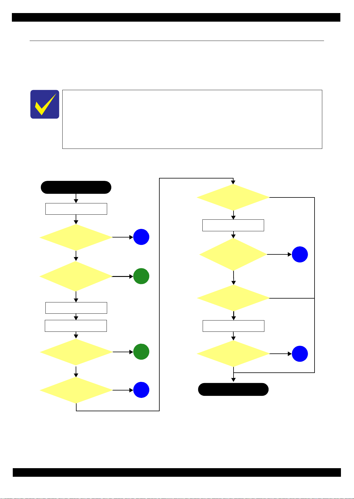
1.1.1 Troubleshooting Workflow
The following page describes the troubleshooting workflow. Follow the flow when troubleshooting problems.
Revision B
Figure 1-1. Troubleshooting Workflow (1)
Troubleshooting Troubleshooting Workflow 10
Confidential
Page 11
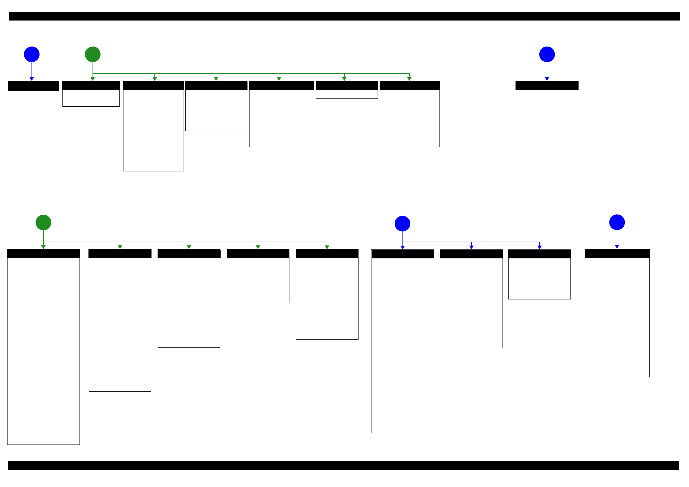
Epson ET-4550, L655/656 Revision B
The power-on
1
sequence does not
start (p 10)
No Power
[Presumable Cause]
• Power Supply Unit
damage
• Main Board damage
• Panel Unit damage
[Major Troubleshooting]
• Power Supply Unit
replacement
• Main Board
replacement
• Panel Unit replacement
* : If the printer can turn on but turns
off right away, the protection
circuit may cut off the power due
to an error such as a circuit
failure.
*
Please refer to " 1.3 Fatal Error
Code List (p14)"for
troubleshooting.
Error is indicated during printing nozzle check pattern (p 10)
3
2
Fatal error
Error is indicated during
power-on sequence (p 10)
Maintenance error
[Occurrence Condition]
This error occurs when
maintenance counter in
EEPROM exceeds the specified
value.
[Major Occurrence Timing]
• Power-on timing
• Print start timing
• Paper eject timing
• Cleaning timing
[Major Troubleshooting]
• Replace Maintenance Box
• Paper Guide Lower Porous
Pad replacement
• Maintenance counter reset
(only Paper Guide Lower
Porous Pad)
Incomplete Initial Ink Charge
[Occurrence Condition]
LCD and STM indicate "Initial
ink charging is not complete".
[Major Occurrence Timing]
• Power-on timing
[Major Troubleshooting]
• Perform initial ink charge
Ink End error
[Occurrence Condition]
This error occurs when ink counter
reaches ink end level.
[Major Occurrence Timing]
• Power-on timing
• Print start timing
• Paper eject timing
• Cleaning timing
[Major Troubleshooting]
• Refill ink and reset ink counter
by panel.
Paper Jam error
Please refer to " Paper Jam error".
CR Fixing Tape error
[Occurrence Condition]
This error occurs if a paper jam
occurs during the power-on
sequence before initial ink
charge.
[Major Occurrence Timing]
Power-on timing
(before initial ink charge)
[Major Troubleshooting]
Open the scanner unit and
remove the CR fixing tape.
Problems related to print result or during printing(p 10)
4
Scanning cannot be
performed
5
successfully (p 10)
Scanner failure
[Presumable Cause]
• Contamination of Scanner
Glass
• Contamination of Document
Pad
• CIS Unit bonding failure
• CIS Unit damage
• Scanner Motor damage
[Major Troubleshooting]
• Scanner Glass cleaning
• Document Pad cleaning
• Document Pad replacement
• CIS Unit replacement
• Scanner Motor replacement
• Scanner Unit replacement
ADF does not
operate normally
6
(p 10)
Paper Jam error
[Occurrence Condition]
This error occurs when top/bottom of
paper is not detected by PE Sensor in the
specified steps of paper feeding
operation correctly.
[Major Occurrence Timing]
• Power-on timing
• Paper loading timing
• Paper eject timin g
• Duplex print timing
[Major Troubleshooting]
1 remove the jammed paper by opening
Scanner Unit or Printer Cover.
2 Push “Start” button.
3 If not resolved by 2), check the
following.
• Foreign material, bits of paper
• Part come-off
• PE Lever
• PE Sensor
• Float of Paper Guide Front Porous
Pad
•Main Board
• PW Sensor
[NOTE]
* If an error occurs during printing, the
page where the error occurred is skipped
and the printing resumes from the next
page.
* If an error occurs during duplex
printing, the following are performed.
• If an error occurs during the front
face of duplex printing, the page
where the error occurred and the
next page are skipped and the
printing resumes from the page
after the next.
• If an error occurs during the back
face of duplex printing, the page
where the error occurred is skipped
and the printing resumes from the
next page.
No Paper error
[Occurrence Condition]
This error occurs when top of
paper is not detected by PE Sensor
in the specified steps of paper
loading operation correctly.
[Major Occurrence Timing]
Paper loading timing
[Major Troubleshooting]
1 Put paper in cassette and push
“START” button.
2 If a paper stops before reaching
PE Sensor, remove it and
check the paper condition.
3 A) If no damage on the paper, s et
edge guide correctly after
putting paper in ca ssette and
push “PRINT” button again.
B) If damage on the paper, check
foreign materials / parts come off / parts transforma tion in
paper path.
4 If not resolved by 3-A) & 3-B),
check the following.
• Pickup Roller
• Duplex Unit
• PE Sensor
• Main Board
• PF Motor
• Casette Assy
Double Feed error
[Occurrence Condition]
This error occurs on the following
cases.
• A paper is ejected without
printing during paper loading
operation.
• Actual paper length is longer
than theoretical one.
[Major Occurrence Timing]
Paper loading timing
[Major Troubleshooting]
• PE Lever replacement
• PE Sensor replacement
• PW Sensor replacement
• Main Board replacement
[NOTE]
This error occurs only for manual
duplex print.
No Paper Cassette error
[Occurrence Condition]
This error occurs if one of the
cassettes is not installed.
[Major Occurrence Timing]
Paper loading timing
(Front loading)
[Major Troubleshooting]
Install the Cassette Assy.
Paper Size Unmatch error
[Occurrence Condition]
This error occurs when actual
paper size is not matched to
theoretical one.
[Major Occurrence Timing]
• Duplex print timing
• FAX data print timing
[Major Troubleshooting]
1 Put correct sized paper in
cassette, and push “START”
button.
2 If not resolved by step 1),
check the following points.
• PE Lever
•PE Sensor
• PW Sensor
• Main Board
Poor Printing
[Phenomenon]
• Poor printing quality
• Ink stain on paper
• Dot missing
• Paper eject without printing
[Presumable Cause]
• Driver / Panel mis-setting
• Contamination of CR scale
• Contamination of Printhead
Cover
• Printhead damage
• Ink clogging of Printhead
• Contamination on Cap Unit /
Wiper of Inksystem Assy
• Inksystem Assy damage
• Float of Paper Guide Front
Porous Pad
• Narrow PG
• PE Lever damage
• PE Sensor damage
• PW Sensor damage
[Major Troubleshooting]
• Driver / Panel re-setting
• CR Scale replacement
• Printhead cover cleaning
• Printhead cleaning
• Refill ink
• Printhead replacement
• Rubber cleaning of Cap Unit of
Inksystem Assy
• Inksystem Assy replacement
• Paper Guide Front Porous Pad
re-installation
• PG readjustment
• Printer Mechanism
replacement
• PE Lever replacement
• PE Sensor replacement
• PW Sensor replacement
• Main Board replacement
Poor Paper Loading
[Presumable Cause]
• Use of 3rd party media
• Edge guide mis-setting
• Foreign material
• Part come-off
• Contamination of paper feed
roller (Duplex Unit)
• Cassette Assy damage
• Pickup Roller deterioration,
contamination
• Contamination of PF roller
[Major Troubleshooting]
• Recommendation of EPSON
media
• Edge guide re-setting
• Foreign material removal
• Part re-installat ion
• PF Roller replacement
• Cassette Assy replacement
• Pickup Roller replacement
Abnormal Noise
[Presumable Cause]
• Foreign material
• Insufficient grease
• Gear damage
[Major Troubleshooting]
• Foreign material removal
• Lubrication of grease
• Gear replacement
ADF failure
[Phenomenon]
• No paper feed
• Double feed
• Paper jam
• Paper skew
[Presumable Cause]
• Wear of Pickup Roller
• Wear of ADF Pad Assy
• Gear damage
• Scanner Motor damage
• Contamination of Scanner Glass
• ADF Paper Support Assy
damage
• Foreign material
• ADF Cover Assy damage
• Wear of EJ Roller
• ADF Sensors damage
[Major Troubleshooting]
• ADF Cover Assy replacement
• ADF Pad Assy replacement
• Scanner Glass cleaning
• ADF Paper Support Assy
replacement
• Foreign material removal
• Scanner Unit replacement
• ADF Unit replacement
Figure 1-2. Troubleshooting Workflow (2)
Troubleshooting Troubleshooting Workflow 11
Confidential
Page 12

Epson ET-4550, L655/656 Revision B
080
CRLock
CRUnit
HP
1.2 Power-On Sequence
This section describes the power-on sequences for this product. The preconditions are as follows.
Power-on sequence (See Table 1-1.)
Turning on the printer after turning it off without an error.
The power was turned off normally at the previous shut down.
Initial ink charge has finished and every ink tank has sufficient ink.
No paper on the paper path.
The Printhead is capped by the cap of the Ink System and the CR Lock is engaged normally.
Table 1-1. Normal Power-on Sequence
CR Unit/PF Roller
movement and position
*2
1. Printhead initialization
1-1.Initializes the Printhead.
*
Operation
*3
1
2. Maintenance error de tec t ion
2-1.Checks the tube maintenance counter for ink tube errors.
2-2.Checks the waste ink counter if the waste ink overflow is occurring.
3. Releasing the CR lock
3-1.The PF Motor rotates clockwise, and releases the CR lock.
4. Seeking the home position
4-1.The CR Unit moves to the 0-digit side slowly and confirms it touches the Right Frame.
4-2.By regarding the position where the CR Unit touches the Right Frame as the specified distance from the origin, the
home position is determined. Thereafter, the position of the CR Unit is monitored based on the information
provided by the CR Encoder Sensor.
4-3.The CR Unit slowly moves to its home position.
4-4.The PF Roller rotates clockwise for approximately 1 second.
5. Low temperature operation sequence
5-1.The CR Unit moves between around the switch lever and in front of the Left Frame two times.
*4
080 HP
080 HP
080 HP
080 HP
080 HP
080 HP
080 HP
Troubleshooting 12
Confidential
Page 13

Epson ET-4550, L655/656 Revision B
Table 1-1. Normal Power-on Sequence
*
Operation
1
6. Adjustment of CR acceleration delay
6-1.The CR Unit moves between around the switch lever and in front of the Left Frame two times.
CR Unit/PF Roller
movement and position
*2
080 HP
6-2.The measured CR acceleration delay time is recorded in the EEPROM.
7. CR measurement
7-1.The CR Unit moves until it touches the Right Frame.
7-2.The CR Unit slowly moves to its home position, and then moves until it touches the Right Frame again.
7-3.The CR Motor carries out the measurement drive, and the measured value is recorded in the EEPROM.
7-4.The CR Unit slowly moves to its home position
8. Ink detection and initializing the Ink System
*5
8-1.The CR Unit moves slowly until it touches the Right Frame, and then moves back to its home position.
Note *1: The rotation directions of the PF Motor are as follows.
Clockwise: Paper is fed normally
Counterclockwise: Paper is fed backward
*2: The conditions of the CR lock are as follows.
Red CR lock is set
White CR lock is released
*3: If it cannot be initialized, the fatal error occurs.
*4: Executed when the detected temperature is under 5
o
C (41oF) by the thermistor on the Printhead.
*5: The empty suction operation may occur depending on situations.
080 HP
080 HP
080 HP
080 HP
080 HP
080 HP
Troubleshooting 13
Confidential
Page 14

Epson ET-4550, L655/656 Revision B
1.3 Fatal Error Code List
This section describes the fatal error code and the possible cause for this product.
Table 1-2. Fatal Error List
Error type
ADF/Scanner
Error
code
0x01
(100001)
0x02
(100002)
0x03
(100003)
0x04
(100004)
0x05
(100005)
0x06
(100006)
0x09
(100009)
0x0A
(100010)
0x0B
(100011)
0x0D
(100013)
0x0E
(100014)
0x10
(100016)
0x11
(100017)
0x12
(100018)
0x13
(100019)
0x14
(100020)
0x20
(100032)
0x30
(100048)
Error name Possible cause
• ADF Encoder failure (contaminated/detached scale, Encoder Board
ADF PID excess speed error
ADF PID reverse error
ADF PID lock error
ADF PID acceleration lock error
ADF PID excess load error
ADF PID driving time error • Main Board failure
ADF BS+ excess speed error
ADF BS+ reverse error
ADF BS+ lock error
ADF BS+ excess load error
ADF BS+ driving time error • Main Board failure
HP detection failure
Contact detection distance exceeded
Opposite side contact detection distance
exceeded error
Wrong contact detection distance error
Measurement error
LED light failure
Option error • Main Board failure
failure)
• Motor driver failure (Main Board failure)
• ADF Encoder failure (contaminated/detached scale, Encoder Board
failure)
•Paper jam
• ADF Encoder failure (contaminated/detached scale, Encoder Board
failure)
• Scanner Motor failure
•Paper jam
• Cable disconnection
• ADF Encoder failure (contaminated/detached scale, Encoder Board
failure)
• Motor driver failure (Main Board failure)
• ADF Encoder failure (contaminated/detached scale, Encoder Board
failure)
•Paper jam
• ADF Encoder failure (contaminated/detached scale, Encoder Board
failure)
• Scanner Motor failure
•Paper jam
• Cable disconnection
• CIS Unit failure
• Scanner Housing failure
• Main Board failure
• Insufficient grease
• Foreign object
• FFC for CIS failure / FFC for CIS connection failure
• CIS Unit failure
• Scanner Housing failure (Including wrong attachment of the origin
mark)
• Main Board failure
• FFC for CIS failure / FFC for CIS connection failure
• Motor failure
• Scanner drive mechanism was overloaded.
• Insufficient grease
• Foreign object
• Lack of gears
• Deformation of the shaft
• CIS Unit failure
• Main Board failure
Troubleshooting 14
Confidential
Page 15

Epson ET-4550, L655/656 Revision B
Table 1-2. Fatal Error List
Error type
ADF/Scanner
Printer
Error
code
0x36
(100054)
0x41
(100065)
0x42
(100066)
0x43
(100067)
0x44
(100068)
0x45
(100069)
0x46
(100070)
0x49
(100073)
0x4A
(100074)
0x4B
(100075)
0x4D
(100077)
0x4E
(100078)
0x51
(100081)
0x52
(100082)
0x53
(100083)
0x54
(100084)
0x55
(100085)
0x60
(000096)
0x68
(000104)
0x69
(000105)
Error name Possible cause
•Paper jam
Paper jam error
FB PID excess speed error
FB PID reverse error
FB PID lock error • ADF Encoder failure (contaminated/detached scale, Encoder Board
FB PID acceleration lock error
FB PID excess load error
FB PID driving time error • Main Board failure
FB BS+ excess speed error
FB BS+ reverse error
FB BS+ lock error
FB BS+ excess load error
FB BS+ driving time error • Main Board failure
Auto judge Fatal Error 1
Auto judge Fatal Error 2
Auto judge Fatal Error 3
Auto judge Fatal Error 4
Auto judge Fatal Error 5
Home position
Valve initialization timing contact
detection error
I/S clutch action timing contact detection
error
• Foreign object
• Loading/ejecting papers out of the standard range or curled papers
• Using long papers (Legal or longer)
• ADF Encoder failure (contaminated/detached scale, Encoder Board
failure)
• Motor driver failure (Main Board failure)
• ADF Encoder failure (contaminated/detached scale, Encoder Board
failure)
• Paper jam error
failure)
• Scanner Motor failure
• ADF drive mechanism overload (assembling failure, foreign object,
lubrication failure)
• Cable disconnection
• ADF Encoder failure (contaminated/detached scale, Encoder Board
failure)
• Motor driver failure (Main Board failure)
• ADF Encoder failure (contaminated/detached scale, Encoder Board
failure)
• Paper jam error
• ADF Encoder failure (contaminated/detached scale, Encoder Board
failure)
• Scanner Motor failure
• ADF drive mechanism overload (assembling failure, foreign object,
lubrication failure)
• Cable disconnection
---*
• Carriage overload error (paper jam/foreign object)
• Deformation of the Main Frame
• Ink system failure
• CR Motor failure
• Deformation of the Front Frame
• CR Encoder failure (contaminated/detached scale, Encoder Board
failure)
• Cable disconnection
• Ink system failure
• Main Board failure
Troubleshooting 15
Confidential
Page 16

Epson ET-4550, L655/656 Revision B
Table 1-2. Fatal Error List
Error type
Printer
Error
code
0x6B
(000107)
0x7F
(000111)
0x8D
(000141)
0x8E
(000142)
0x8F
(000143)
0x93
(000147)
0x97
(000151)
0x9A
(000154)
0x9B
(000155)
0x9C
(000156)
0x9D
(000157)
0x9E
(000158)
0x9F
(000159)
0xE1
(000225)
0xE2
(000226)
0xE3
(000227)
0xE4
(000228)
0xE5
(000229)
Error name Possible cause
• PF Encoder failure (contaminated/detached scale, Encoder Board
PF runaway error
Inspection mode timing error
Factor error other than printer device
Driver mismatch error An unsupported driver was used
EEPROM verify error (by command)
PE Sensor error
Head drive circuit excessive voltage error
Circuit error (include blowout of a fuse)
Transistor temperature error
X-Hot detect error (pre printing)
X-Hot detect error (after flushing)
Head temperature error
Printing inspection less mode error
CR PID excess load error
CR PID excess speed error
CR PID reverse error
CR PID lock error
CR PID speed fall error
failure)
• Motor driver failure
This error occurs if the printer becomes a fatal error status due to a
failure of parts other than the printer such as the scanner or ADF.
• PE Sensor failure
• Main Board failure
• Head FFC failure
• Main Board failure
• Main Board failure
• Printhead failure
• Main Board failure
This error occurs if the printing or manual cleaning are performed in
Printing inspection less mode.
• CR Encoder failure (contaminated/detached scale, Encoder Board
failure)
• CR Motor failure
• Carriage overload error (paper jam/foreign object)
• Cable disconnection
• CR Encoder failure (contaminated/detached scale, Encoder Board
failure)
• Motor driver failure (Main Board failure)
• Slipping teeth of the CR Timing Belt
• Improper tension of the CR Timing Belt
• CR Encoder failure (contaminated/detached scale, Encoder Board
failure)
• Slipping teeth of the CR Timing Belt
• Improper tension of the CR Timing Belt
• Carriage overload error (paper jam/foreign object)
• CR Encoder failure (contaminated/detached scale, Encoder Board
failure)
• CR Motor failure
• Carriage overload error (paper jam/foreign object)
• Cable disconnection
• CR Encoder failure (contaminated/detached scale, Encoder Board
failure)
• Motor driver failure (Main Board failure)
• Slipping teeth of the CR Timing Belt
• Improper tension of the CR Timing Belt
• Carriage overload error (paper jam/foreign object)
---*
---*
Troubleshooting 16
Confidential
Page 17

Epson ET-4550, L655/656 Revision B
Table 1-2. Fatal Error List
Error type
Printer
System Error
Error
code
0xE8
(000232)
0xE9
(000233)
0xEA
(000234)
0xEE
(000238)
0xEF
(000239)
0xF1
(000241)
0xF2
(000242)
0xF3
(000243)
0xF4
(000244)
0xF8
(000248)
0xF9
(000249)
0xFA
(000250)
0xFE
(000254)
0xFF
(000255)
202620 WiFi error
205102 Card board error
CR load position reverse error
CR load position excess speed error
CR load position excess load error
CR PID driving time error
CR load position excess driving time
error
PF PID excess load error
PF PID excess speed error
PF PID reverse error
PF PID lock error
PF load position reverse error
PF load position reverse error
PF load position excess load error
PF PID driving time error
PF load position excess driving time error
Error name Possible cause
• CR Encoder failure (contaminated/detached scale, Encoder Board
failure)
• Slipping teeth of the CR Timing Belt
• Improper tension of the CR Timing Belt
• Carriage overload error (paper jam/foreign object)
• CR Encoder failure (contaminated/detached scale, Encoder Board
failure)
• Motor driver failure (Main Board failure)
• Slipping teeth of the CR Timing Belt
• Improper tension of the CR Timing Belt
• CR Encoder failure (contaminated/detached scale, Encoder Board
failure)
• CR Motor failure
• Carriage overload error (paper jam/foreign object)
• Cable disconnection
• Main Board failure
• PF Encoder failure (contaminated/detached scale, Encoder Board
failure)
• PF Motor failure
• PF drive mechanism overload (paper jam/foreign object)
• Cable disconnection
• PF Encoder failure (contaminated/detached scale, Encoder Board
failure)
• Motor driver failure (Main Board failure)
• Slipping gears have occurred around the PF Motor gears.
• PF Encoder failure (contaminated/detached scale, Encoder Board
failure)
• Slipping gears have occurred around the PF Motor gears.
•Paper jam
• PF Encoder failure (contaminated/detached scale, Encoder Board
failure)
• PF Motor failure
• PF drive mechanism overload (paper jam/foreign object)
• Cable disconnection
• PF Encoder failure (contaminated/detached scale, Encoder Board
failure)
• Slipping gears have occurred around the PF Motor gears.
• PF Encoder failure (contaminated/detached scale, Encoder Board
failure)
• Motor driver failure (Main Board failure)
• Slipping gears have occurred around the PF Motor gears.
• PF Encoder failure (contaminated/detached scale, Encoder Board
failure)
• PF Motor failure
• PF drive mechanism overload (paper jam/foreign object)
• Cable disconnection
• Main Board failure
WiFi board failure
Card board failure
Troubleshooting 17
Confidential
Page 18

Epson ET-4550, L655/656 Revision B
Note "*": Not occurs except in manufacturing process
Troubleshooting 18
Confidential
Page 19

CHAPTER 2
DISASSEMBLY/REASSEMBLY
Confidential
Page 20

Epson ET-4550, L655/656 Revision B
2.1 Overview
This chapter describes procedures for disassembling the main parts/units of ET-4550, L655/656. Unless
otherwise specified, disassembled parts/units can be reassembled by reversing the disassembly procedure. See
the cautions or tips for disassembly/reassembly described in "2.4 Detailed Disassembly/Reassembly Procedure
for each Part/Unit (p45)".
Read the " Safety Precautions (p3)" before disassembling and reassembling.
When you have to remove units or parts that are not described in this chapter, see the exploded diagrams of SPI
(Service Parts Information).
2.1.1 Tools
Use only specified tools to avoid damaging the printer.
Name Availability EPSON Part Code
(+) Phillips screwdriver #1 O 1080530
(+) Phillips screwdriver #2 O --Flathead screwdriver O --Flathead Precision screwdriver #1 O --Tweezers O --Longnose pliers O --Nippers O ---
Note 1: Some of the tools listed above are commercially available.
2: EPSON provides the tools listed with EPSON part code.
2.1.2 Jigs
Name Q’ty EPSON Part Code
Thickness gauge (1.48mm) 1 Commercially available
Thickness gauge (1.76mm) 1 Commercially available
Teflon tape (thickness: 0.08 mm) 1 Commercially available
Tube clip 4 Commercially available
Disassembly/Reassembly Overview 20
Confidential
Page 21
Epson ET-4550, L655/656 Revision B
4 3
Front
7
1
2
6
5
Right
8
9
13
Left
1112
Rear
10
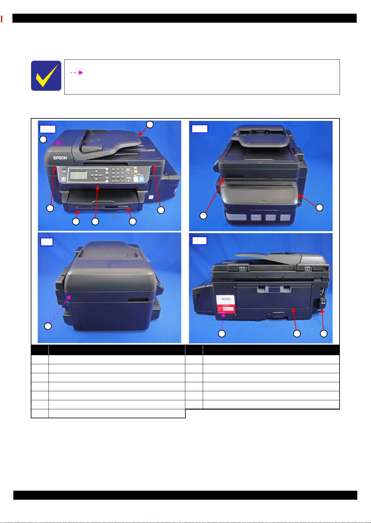
2.1.3 Locations of the Parts/Units
This section shows the locations of the main parts/units of ET-4550, L655/656.
The parts/units which can not be seen in the following pictures are indicated in dotted lines
().
Exterior parts
No. Name No. Name
1 ADF Document Support (p39) 8 Ink Tank Unit (p39)
2 ADF Unit (p40) 9 Scanner Unit (p40)
3 Stacker Assy (p39) 10 FAX Filter Assy (p42)*
4 Panel Unit (p39) 11 Duplex Unit (p37 )
5 Cassette Assy (p37) 12 Waste Ink Pad Assy (p39)
6 ADF LD Cover Assy (p39) 13 Hinge (p39)
Disassembly/Reassembly Overview 21
7 ADF Pad Assy (p40)
Note "*": The FAX Filter Assy is mounted only on models for some country/region.
Figure 2-1. Exterior Parts
Confidential
Page 22
Epson ET-4550, L655/656 Revision B
1 2 3
4
5
1
2
4
5
3
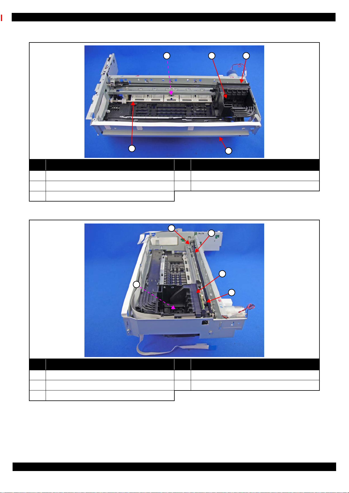
Printer mechanism
No. Name No. Name
1 PE Sensor Lever Assy (p41) 4 Front Frame (p41)
2 Printhead (p39) 5 PF Roller (p43)
3 CR Unit (p43)
Figure 2-2. Printer Mechanism: Front
No. Name No. Name
1 CR Scale & Spring (p41) 4 CR Encoder Sensor (p43)
2 CR Timing Belt (p43) 5 PW Sensor (p43)
3 Holder Board (p39)
Figure 2-3. Printer Mechanism: Right
Disassembly/Reassembly Overview 22
Confidential
Page 23
Epson ET-4550, L655/656 Revision B
1 2 3
4
5
6
1
578
2
6
4
3
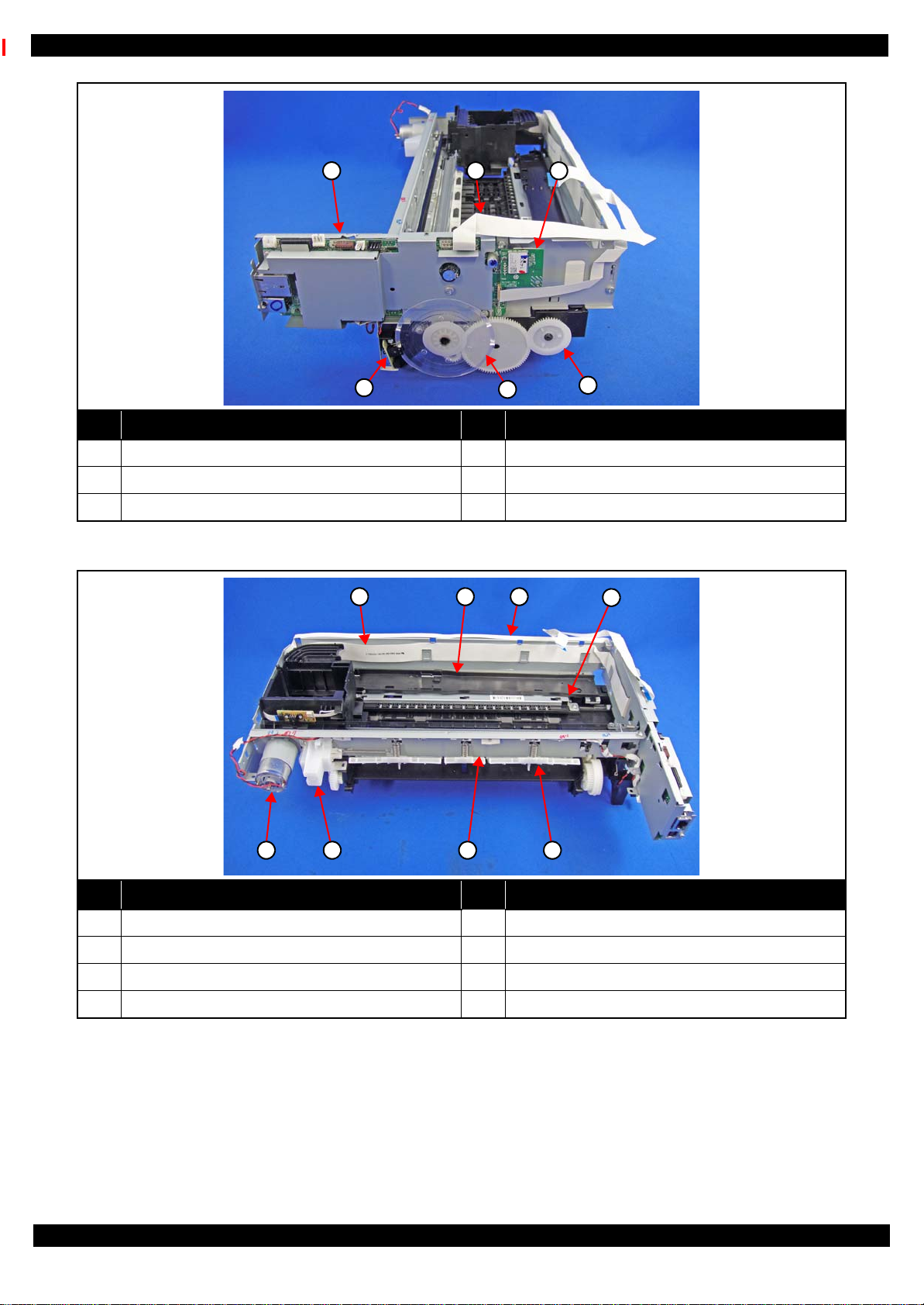
No. Name No. Name
1 Main Board Assy (p41) 4 EJ Roller Gear (p41)
2 Panel FFC (p39) 5 PF Scale (p41)
3 Wireless LAN Module (p41) 6 PF Encoder (p41)
Figure 2-4. Printer Mechanism: Left
No. Name No. Name
1 Head FFC (p39) 5 Paper Guide Upper Assy (p41)
2 Tube Guide (p39) 6 Main Frame Assy (p41)
3 Ink End Sensor FFC (p41) 7 Holder Cam Assy (p41)
4 Star Wheel Holder Assy (p41) 8 CR Motor (p43)
Figure 2-5. Printer Mechanism: Rear
Disassembly/Reassembly Overview 23
Confidential
Page 24

Epson ET-4550, L655/656 Revision B
4
7 5
2 3
6
1
1
7
4
3
6
8
5
Front Rear
2
Ink Tank Unit
No. Name No. Name
1 Tube Guide Sheet (p44) 5 Tube Lock (p44)
2 Adapter(Bk) (p44), Adapter(C/M/Y) (p44) 6 Adapter Cover (p44)
3 Ink Supply Adapter Tube Assy (p44) 7 Tube Clamp (x3) (p44)
4 Joint (p44)
Figure 2-6. Ink Tank Unit (1)
No. Name No. Name
1 Ink Tank Cover (p39) 5 Ink Supply Tank (C/M/Y) (p44)
2 Ink Tank Housing Upper (p44) 6 Ink End Sensor Assy (p44)
3 Cap Tank (p44) 7 Ink Supply Tank (Bk) (p44)
4 Ink Tank Housing Lower (p44) 8 Ink Supply Tank Tube Assy (p44)
Figure 2-7. Ink Tank Unit (2)
Disassembly/Reassembly Overview 24
Confidential
Page 25

Epson ET-4550, L655/656 Revision B
2.1.4 Standard Operation Time for servicing the product
The following are the standard operation time for servicing the product. Those are based on the MTTR result
measured using a prototype of ET-4550, L655/656 that has the most functions among these product series. For
ET-4550, L655/656 the standard operation time differs slightly due to the differences in structure, however,
perform servicing referring to this operation standard time.
The underlined parts/units are supplied as After Service Parts.
Table 2-1. Standard Operation Time for servicing the product
Time
Parts/Unit
Replacement
Panel Unit 0:45 0:15 1:00
Panel Board 2:02 0:15 2:17
Panel Buttons 2:33 --- 2:33
LCD Unit 2:25 0:15 2:40
Panel Housing Assy 2:25 --- 2:25
Waste Ink Pad Assy
Pickup Roller Assy
Adapter Cover
Holder Board
Printhead
Printhead Grounding Plate 2:12 --- 2:12
Head FFC 3:29 --- 3:29
Paper Stopper Assy 0:43 --- 0:43
ADF LD Cover Assy
Gear Cover 0:52 --- 0:52
ADF Document Support
Spur Gear 25.8/20.4, Combination Gear 24.9.6 1:00 --- 1:00
Bevel Gear Shaft 10.4 0:58 --- 0:58
Document Mat 0:13 --- 0:13
Stacker Assy
Ink Tank Cover
Ink End Sensor Lumirror
Ink Tank Unit
Ink Tank Housing Lower
Cap Tank
Ink Tank Housing Upper
Ink End Sensor Assy
Ink Supply Tank (Bk, C/M/Y)
Ink Supply Tank Tube Assy
Rail Cassette 3:47 --- 3:47
Tube Clamp (x3)
Tube Lock
Joint
Adapter (Bk, C/M/Y)
Tube Guide Sheet
0:37 0:12 0:49
0:11 --- 0:11
0:09 --- 0:09
0:25 --- 0:25
1:38 13:06 14:44
0:09 --- 0:09
0:19 --- 0:19
0:08 --- 0:08
0:08 --- 0:08
0:36 --- 0:36
3:04 --- 3:04
3:45 --- 3:45
0:34 --- 0:34
4:27 --- 4:27
5:23 --- 5:23
8:42 --- 8:42
8:43 --- 8:43
1:06 --- 1:06
0:28 --- 0:28
0:12 --- 0:12
2:10 --- 2:10
1:58 --- 1:58
Adjustment/
Inspection
Total
Disassembly/Reassembly Overview 25
Confidential
Page 26

Epson ET-4550, L655/656 Revision B
Table 2-1. Standard Operation Time for servicing the product
Time
Parts/Unit
Replacement
Ink Supply Adapter Tube Assy 5:48 --- 5:48
Housing Upper
Speaker 0:52 --- 0:52
Tube Guide
Panel FFC
ADF/Scanner Unit 3:03 --- 3:03
ADF Unit
ADF Hinge Holder 4:02 --- 4:02
ADF Hinge Right 4:09 --- 4:09
ADF Hinge Left 3:53 --- 3:53
Cable Holder 3:48 --- 3:48
ADF Frame Assy 5:33 --- 5:33
ADF Frame Upper Assy 6:24 --- 6:24
ADF Pad Assy
ADF Frame Lower Assy 6:24 --- 6:24
Scanner Unit
Scanner Housing Upper Assy 5:03 --- 5:03
CIS Module 5:12 --- 5:12
Combination Gear 19.2.12.6 5:18 --- 5:18
Combination Gear 18.4.9.66 5:22 --- 5:22
Scanner Carriage Unit 5:31 0:58 6:29
Scanner FFC 6:28 --- 6:28
Scanner Housing Lower Assy 6:28 --- 6:28
Hinge
PS Unit
Printer Mechanism 6:21 --- 6:21
Main Board Assy
Main Board Shield Plate Upper 11:13 --- 11:13
Main Board
Main Board Shield Plate Lower 11:18 --- 11:18
Holder Cam Assy 6:55 --- 6:55
CR Scale
CR Driven Pulley Assy 7:33 --- 7:33
CR Scale Holder 7:17 --- 7:17
Right Frame 7:13 --- 7:13
Paper Guide Upper Assy
PE Sensor Lever Assy
PF Encoder Sensor
PF Scale 7:11 --- 7:11
Wireless LAN Module
Read OK
Read NG 11:44 20:39
Read OK
Read NG 11:44 22:58
1:51 --- 1:51
3:07 --- 3:07
2:36 --- 2:36
3:41 --- 3:41
6:53 --- 6:53
3:41 0:58 4:39
3:17 --- 3:17
3:15 1:40 4:55
8:55
11:18
6:49 --- 6:49
7:12 4:03 11:15
7:17 0:12 7:29
6:56 --- 6:56
6:26 --- 6:26
Adjustment/
Inspection
1:28 10:23
1:28 12:46
Total
Disassembly/Reassembly Overview 26
Confidential
Page 27

Epson ET-4550, L655/656 Revision B
Table 2-1. Standard Operation Time for servicing the product
Time
Parts/Unit
Replacement
Adjustment/
Inspection
Total
Ink End Sensor FFC
EJ Roller Gear 9:03 1:45 10:48
Front Frame 10:59 5:34 16:33
Star Wheel Holder Assy 11:38 1:45 13:23
Star Wheel Holder Shield Plate 11:48 --- 11:48
Star Wheel Holder 11:48 1:45 13:33
EJ Roller 11:56 1:45 13:41
Main Frame Assy 11:20 7:18 18:38
PW Sensor Cover 11:33 --- 11:33
PW Sensor
CR Motor 12:24 0:22 12:46
CR Unit 12:35 5:12 17:47
CR Encoder Sensor 13:01 --- 13:01
CR Pressing Plate/Compression Spring3.71 13:26 --- 13:26
CR Timing Belt 12:49 --- 12:49
Carriage 14:24 5:12 19:36
Main Frame 12:35 6:45 19:20
ASF Cover Assy 11:34 --- 11:34
ASF Drive Transmission Gears 11:41 --- 11:41
PF Roller Stopper 11:41 --- 11:41
PF Roller 11:51 2:15 14:06
PF Drive Transmission Gear 12:32 --- 12:32
Planet Gear Assy 12:44 --- 12:44
Planet Release Holder Assy 13:01 --- 13:01
PF Motor Gears 11:57 --- 11:57
PF Motor 12:47 0:20 13:07
Frame Base Assy 6:21 --- 6:21
Ink System
Pickup Gear 7:10 --- 7:10
Pickup Driven Shaft 7:21 --- 7:21
Stacker Guide Left 6:32 --- 6:32
Stacker Guide Right 6:32 --- 6:32
PE Sensor
Cassette Sensor
Pickup Lever 6:33 --- 6:33
Cassette Lock Lever/Torsion Spring 426 6:42 --- 6:42
I/F Cover 6:38 --- 6:38
FAX Unit
FAX Filter Assy* 7:20 --- 7:20
FAX Filter Board
7:01 --- 7:01
11:51 2:41 14:32
7:00 --- 7:00
6:39 0:31 7:10
7:18 --- 7:18
6:49 --- 6:49
6:53 --- 6:53
Note "*": The FAX Filter Assy is mounted only on models for some country/region.
Disassembly/Reassembly Overview 27
Confidential
Page 28

Epson ET-4550, L655/656 Revision B
Ink Supply Tank Assy
Ventilation Hole
Ink Supply Tank Assy
OK
NG
2.1.5 Checks and Precautions before Disassembling
2.1.5.1 Factors which Affect the Print Quality
HOW TO PLACE THE INK TANK ASSY WHEN DISASSEMBLING/REASSEMBLING
The film under sealing film attached on the Ink Supply Tank Assy of this printer is ventilation film. The ink in the
ink tanks is vented to atmosphere through this film to keep ink supply to the Printhead stable. If the film gets wet
with ink, the ink in the tanks is not properly vented and printing may not be capable.
In order to prevent this from occurring, make sure to place the Ink Supply Tank Assy as shown below after
removing it.
Figure 2-8. How to Place the Ink Tank Assy
Disassembly/Reassembly Overview 28
Confidential
Page 29

Epson ET-4550, L655/656 Revision B
A
C
B
Joint Ink Supply Tank
Ink Supply Tank Tube AssyInk Supply Adapter Tube Assy
Adapter
2.1.5.2 Factors which Affect the Safety of Service Personnel such as Ink Leakage during Operation
Ink may spill when removing the following parts from ET-4550, L655/656.
This section describes the parts that may cause ink spill and the means to minimize the ink spill when removing
the parts.
THE PARTS THAT MAY CAUSE INK SPILL WHEN REMOVING
Parts When ink may spill Location
Joint Removing the Ink Supply Tank Tube Assy / Ink Supply Adapter Tube Assy from
the Joint
A
Ink Supply
Tank
Ink Supply
Tank Tube Assy
Adapter Removing the Ink Supply Adapter Tube Assy from the Adapter C
Ink Supply
Adapter Tube
Assy
Note : These parts are indicated with the icon in disassembly/reassembly flowchart. (See "2.3 Disassembly/Reassembly Procedures
(p37)".)
• Removing the tubes of the Ink Supply Tank Tube Assy from the Joint
• Removing the tubes of the Ink Supply Tank Tube Assy from the Ink Supply Tank
• Removing the Ink Supply Adapter Tube Assy from the Joint
• Removing the Ink Supply Adapter Tube Assy from the Adapter
A, B
A, C
Figure 2-9. Location
Disassembly/Reassembly Overview 29
Confidential
Page 30

Epson ET-4550, L655/656 Revision B
Carriage
Adapter
Ink path
Joint part
Tube Clip
Film
MEANS DO TO MINIMIZE THE INK SPILL
Before disassembling, confirm that the printer is in the following condition.
Adapter is removed
Before disconnecting the joint parts of the ink path, make sure that the Adapter is removed from the Carriage.
Figure 2-10. Adapter
Adapter and Ink tube are disconnected
Before disconnecting the Adapter and the Ink tube, pinch the ink tube with a Tube Clip
When touch the film on the ink path, ink may leak out from the joint part. So touch the plastic part.
Figure 2-11. Adapter and Ink tube
Disassembly/Reassembly Overview 30
Confidential
Page 31

Epson ET-4550, L655/656 Revision B
Ink Tank Unit
DISCHRGING INK FROM THE INK SUPPLY TANK
Discharging ink is recommended only when disconnecting the Ink Supply Tank Tube Assy from the Ink Supply
Tank. Before performing the above disconnection, discharge ink from the Ink Supply Tank as follows.
It is recommended that the ink in the Ink Supply Tank should be d ischarged completely
before proceeding to disassembling/reassembling.
After all the reassembling work is complete, the discharged ink of each color should be
refilled back to the Ink Supply Tank before performing the adjustment. Confirm the
colors indicated on the film of the Ink Supply Tank so as not to mistake them, and make
sure to refill each ink back to the correct tank from the corresponding ink supply hole.
Necessary tools
• Containers (x 4) for each discharged ink
• Injector (with a tip of φ3.2 mm)
• Cloth
• Cotton swab (x 4)
• Tube Clip
Discharging preparation
1. Remove the Ink Tank Cover.
2. Remove the screws (x5) that secure the Ink Tank Unit. (p 47)
3. Remove the Ink Tank Unit from the Frame Base Assy.
Figure 2-12. Discharging preparation (1)
4. Release the Tube Lock from the hooks (x 2) on the Tube Guide . (p 48)
5. Remove the screw that secures the Adapter Cover and remove the Adapter Cover. (p 47)
6. Remove the Tube Guide Sheet from the hooks (x 3) on the CR Unit. (p 48)
7. Release the Ink Supply Adapter Tube Assy from the groove on the CR Unit.
8. Remove the Adapter (x 4) from the CR Unit.
9. To minimize ink spill, pinch the Ink Supply Adapter Tube Assy with a Tube Clip.
Disassembly/Reassembly Overview 31
Confidential
Page 32

Epson ET-4550, L655/656 Revision B
Cloth
Adapter
Tube Clip
Cotton swabs
Hole
Ink Supply Adapter Tube Assy
Frame Base Assy
In the next step, ink may spill from the Ink Supply Adapter Tube Assy when removing it from
the Adapter. Therefore, carry out the next step somewhere other than right over the printer
and be careful not to contaminate the printer and the surroundings.
10. Remove the Ink Supply Adapter Tube Assy from the Adapter.
11. Insert a cotton swab into the end of the Ink Supply Adapter Tube to prevent ink from leaking.
12. Remove the Tube Clip from the Ink Supply Adapter Tube.
13. Repeat Step 9 to Step 12 and disconnect all tubes (x 4) of the Ink Supply Adapter Tube Assy from the
Adapter.
Figure 2-13. Discharging preparation (2)
In the next step, be careful not to let the cotton swabs fall off from the Ink Supply Adapter
Tube.
After inserting the Ink Supply Adapter Tube, pinch it with the Tube Clip.
14. Pull out the Ink Supply Adapter Tube Assy in the direction of the arrow from the hole on the Frame Base
Assy.
.
Figure 2-14. Discharging preparation (3)
Disassembly/Reassembly Overview 32
Confidential
Page 33

Epson ET-4550, L655/656 Revision B
Injector
Ink Supply
Adapter
Tube Assy
Container
Refill hole
Holder
Discharging procedure
1. Insert the tip of the injector to each of the refill holes on the Ink Supply Tank.
2. Suck out ink in the tanks (x 4) of the Ink Supply Tank and transfer it into the containers (x 4) by color.
Figure 2-15. D ischarging Ink (1)
3. Next, Release the Ink Supply Tank Tube from holder of the Ink Supply Tank.
.
Figure 2-16. D ischarging Ink (2)
Disassembly/Reassembly Overview 33
Confidential
Page 34

Epson ET-4550, L655/656 Revision B
Ink Tank Unit
Tip of the Ink Supply
Adapter Tube Assy
Ink Tank Unit
4. Raise the tip of the Ink Supply Adapter Tube. And return the ink of the Ink Tube to the Ink Tank Unit..
Figure 2-17. D ischarging Ink (3)
5. Suck out all the remaining ink while inclining the Ink Tank Unit. And then transfer it to the containers.
Figure 2-18. D ischarging Ink (4)
Disassembly/Reassembly Overview 34
Confidential
Page 35

Epson ET-4550, L655/656 Revision B
2.
Main Frame
Assy
3.
Printer
Mechanism
ADF/Scanner Unit
2. 2.
3.
2.
4.
2.
2.
2.2 Common cautions when disassembling/reassembling the Product
This section describes common cautions when disassembling/reassembling the product.
Before disassembling/reassembling the printer including this product, be sure to read " Safety Precautions (p3)"
and this section.
Item Content Photo/Illustration
When
handling
parts
1. When handling new parts for replacement, ta ke care n ot to contam inate
or damage them.
2. When disassembling/reassembling the parts, take care not to damage
the FFCs/cables/Ink tube if there is a possibility of coming into cont act
with them.
3. When reassembling the product, take care not to let components of the
unit come off.
When
reassembling
When
applying
When installing parts, take care not to damage them when securing them
by tightening screws.
Do not lubricate any part other than those specified. If grease is applied on
such a part, wipe it off completely. ---
grease
External parts Confirm visually that there are no scratches, dirt, and gaps. --Moving parts After reassembling, confirm that there are no abnormal noises and they
work smoothly.
---
Timing belts 1. Take care not to broke them.
2. Confirm that it is installed properly onto the transmissive sections of
the pinion gear/driven roller.
Motors Take care not to damage them. --Sensors 1. Take care not to touch the detector sections.
2. As for the encoder Sensor used with a circular scale, the photo sensor
section should be set over the encoded area of the circular scale.
3. Take care not to get injured by the sharp ends of the board terminal on
the back of the circuit boards when handling the sensors or the
peripheral parts.
Scales 1. Take care not to touch the encoded area.
2. Install it with the black triangular section up. (CR Scale only)
3. Wipe off alcohol before installing. (CR Scale only)
4. Confirm that they do not touch the photo sensors after installation.
Waste ink
pads
1. Take care not to stain your hands with the waste ink soaked in the ink
pads. If ink comes into contact with your hands, wash it off with water
immediately.
2. Take care not to stain the printer's pa rts with the waste i nk soaked in the
ink pads. If ink comes into contact with the parts, wash it off.
(Especially, pay attention to Paper Guide Front/Lower Porous Pad)
Disassembly/Reassembly Common cautions when disassembling/reassembling the Product 35
Confidential
Page 36

Epson ET-4550, L655/656 Revision B
Holder Cam AssyD/E Lever
Protrusion Groove
Ink Supply Tank
A
Housing Upper
2.
Item Content Photo/Illustration
FFCs 1. Be sure to insert them to their connectors on the boards as far as they
will go without any loose connection such as a half-way or slant
connection.
2. Route them along their routing paths.
3. If the double-sided tape that secures the FFCs is not strong enough to
secure them, make sure to replace the tape and secure the FFCs firmly.
Gears When installing gears, pay attention to the following:
• The gear section should not be damaged.
• No foreign material is attached.
• No grease is attached on any parts other than those specified.
PF rollers Do not touch rollers for paper feeding when handling them.
---
---
One Time
parts
ADF/Scanner
Unit
Holder Cam Assy
After removing One Time parts specified in this manual, do not reuse
them, but be sure to replace them with new ones.
When disassembling/reassembling the ADF/Scanner Unit, make sure to
do the work with the unit open to prevent damage to the Hinges.
Install the assy while aligning the protrusion on the D/E Lever with the
groove on the cam of the Holder Cam Assy.
Ink System 1. Take care not to stain your hands with ink.
2. When you connect the ink tube to another part, insert the ink tube up to
the root of the joint to prevent ink leakage and secure the tube with the
tube clamp.
3. If it's hard t o insert the ink tube to the j oint, appl y CR06 to the inserting
part of the ink tube.
Ink Supply
Tank
When handling the Ink Supply Tank, do not put it with the ventilation hole
(A in the figure on the right) downward. (See
before Disassembling (p28)"
)
One Time icon:
---
"2.1.5 Checks and Precautions
MAC
Address
Label
1. Take care not to stain or damage it.
2. When replacing the Housing Upper, transfer the MAC address label to
the new Housing Upper.
Disassembly/Reassembly Common cautions when disassembling/reassembling the Product 36
Confidential
Page 37

Epson ET-4550, L655/656 Revision B
Cassette Assy
Duplex Unit
2.3 Disassembly/Reassembly Procedures
2.3.1 Functional differences between models and component parts
In "2.3.2 Disassembly Flowchart (p38)", the procedures are indicated on the premise that some parts/units are
removed in advance. Make sure to remove the following parts/units before sta r ting disassembly.
Cassette Assy
Duplex Unit
Figure 2-19. Removing the Cassette
Figure 2-20. Removing the Duplex Unit
Disassembly/Reassembly Disassembly/Reassembly Procedures 37
Confidential
Page 38

Epson ET-4550, L655/656 Revision B
Item Description Reference
Parts/unit name
White-letter
Part/unit supplied as an ASP ---
Black-letter
Part/unit not supplied as an ASP ---
Icon
Indicates a practice or condition that could result
in injury or loss of life if not strictly observed.
Indicates the reference page in
blue-letter
Indicates a practice or condition that could result
in damage to, or destruction of equipment if not
strictly observed.
Indicates the reference page in
blue-letter
Indicates the parts that are inevitably broken in
the disassembling procedure, and should be
replaced with a new one for reassembly.
---
Indicates the parts that may cause the ink spill
when they are removed.
"2.1.5 Checks and Precautions
before Disassembling (p28)"
Indicates necessary check items in the
disassembling/assembling procedure.
Indicates the reference page in
blue-letter
Indicates supplementary explanation for
disassembly is given.
Indicates the reference page in
blue-letter
Indicates particular tasks to keep quality of the
units are required.
Indicates the reference page in
blue-letter
Indicates particular routing of cables is required.
Indicates the reference page in
blue-letter
Indicates particular adjustment(s) is/are required. Chapter 3 " Adjustment (p54)"
Indicates lubrication is required. Chapter 4 " Maintenance (p65)"
Indicates the number of screws securing the parts/
units.
---
Indicates the points secured with other than a
screw such as a hook, rib, dowel or the like.
---
Printer
Mechanism
1
4
(p 22) (p 43)
Main Frame Assy
---
---
(p 21) (p 27)
Paper Guide
Upper Assy (p29)
CR Timing Belt
FFC/Cable * 1
Note "*": The boxes with only part names indicates the removal of such parts. If the names of FFCs or cables are
shown, disconnect the FFCs or cables from their connectors.
Black letters indicate a
part/unit not supplied as
an ASP.
The name enclosed in gray
indicate a part/unit that
must be removed on the
way to the target parts.
Shows necessary
procedures before
removing the following
parts.*
Shows the procedure
number on the “FFC/
cable list”.
White letters indicate a
part/unit supplied as
an ASP.
Shows the screw types
and the specified
torque in the “Screw
type/torque list”.
Shows removal/installation
as a unit/assy. is available.
Reference page
2.3.2 Disassembly Flowchart
This section describes procedures for disassembling the parts/units in a flowchart format. For some parts/units,
detailed procedures or precautions are provided (accordingly indicated by icons and cell's color). Refer to the
explanations in the example chart below and perform an appropriate disassembling and assembling procedure.
(See "2.4 Detailed Disassembly/Reassembly Procedure for each Part/Unit (p45)".)
For routing cables, see "2.5 Routing FFCs/cables (p51)".
The example below shows how to see the charts on the following pages.
S2
Disassembly/Reassembly Disassembly/Reassembly Procedures 38
Confidential
Page 39

Epson ET-4550, L655/656 Revision B
S8
S8
S7
S8
S5
S6
S3
S4
S8
S7
S8
S12
S8
S7
S7
START
Panel Unit
(p 46) (p 54)
Alarm cable
Panel FFC
Housing Upper
(p 46)
FFC/Cable* 1
ADF/Scanner
Unit
S7
(p 45) (p 51)
FFC/Cable* 2
Printer
Mechanism
(p 49)
(p 52) (p 54) (p 65)
Frame Base Assy
(p 65)
Waste Ink Pad
Assy
2
2
Pickup Roller
Assy
CR Lock Release
Head FFC
CR Encoder FFC
---
1
3
2
(p 40)
(p 54)
---
Speaker
---
2
4
6
(p 46) (p 51)
Panel FFC
---
Joint (p44)
Tube Lock (p44)
2
1
1
2
(p 40)
(p 51)
Tube Guide
S8
(p 54)
PS Unit cable (CN501)
Hinge
9
1
3
---
PS Unit
---
(p 41)
---
(p 54)
---
---
4
(p 42)
When replacing the Printhead, Holder Board, Adapter or Ink Tank Unit, it is not necessary to
remove the ADF/Scanner Unit. However, the replacing work should be done in a dark narrow
space. If you find the work difficult, remove the ADF/Scanner Unit beforehand.
---
---
1
Adapter Cover
(p44)
Adapter(Bk)
(p44)
Adapter(C/M/Y)
(p44)
Holder Board
---
2
---
Printhead
3
0
(p 47) (p 54)
2
2
Printhead
Grounding Plate
1
---
---
Paper Stopper
Assy
(p 48) (p 65)
Panel Unit (p39)
Housing Upper
(p39)
Head FFC
(p 52)
ADF LD Cover
Assy
2
2
---
---
2
Document Mat
(p 45)
---
---
Stacker Assy
---
---
Ink Tank Cover
---
2
---
2
Rail Cassette
1
---
---
Ink End Sensor FFC
Gear Cover
---
Spur Gear 25.8/
20.4
Combination
Gear 24.9.6
(p 65)
3
---
---
---
ADF Document
Support
---
Bevel Gear Shaft
10.4
(p 65)
---
2
Ink End Sensor
Lumirror
---
3
(p 47)
---
---
Ink Tank Unit
5
5
9
2
(p 47)
(p 44)
(p 44)
Screw type/torque list
Symbol Screw Type Torque
S1
---
---
FFC/cable list
No. FFC/Cable
Disconnect the following FFC and cable
from the connectors on the Main Board.
1
2
• Scanner FFC (CN72)
• Grounding wire
• ADF PE Sensor cable (CN76)
Disconnect the following FFC and cables
from the connectors on the Main Board, and
release their routing.
• FAX FFC (CN1)
• PE Sensor cable (CN13)
• Cassette Sensor cable
• Panel FFC Release (CN2)
• CR Motor Cable Release (CN9)
• Ink End Sensor FFC
• Tube Guide Sheet
S10
S11
S12
S13
S14
S15
S16
S17
S18
C.B.P-TITE SCREW 2x8 F/ZN-3C 4 ± 1kgf·cm
S2
C.B.P-TITE SCREW 2x8 F/ZN-3C 6 ± 1kgf·cm
S3
C.B.P-TITE SCREW 2.5x8 F/ZN-3C 4
S4
C.B.P-TITE SCREW 2x5 F/ZN-3C 2 ± 0.5kgf·cm
S5
C.B.P-TITE SCREW 3x8 F/ZN-3C 6
S6
C.B.S-TITE SCREW 3x8 F/ZB-3C 6 ± 1kgf·cm
S7
C.B.P-TITE SCREW 3x10 F/ZB-3C 6
S8
C.B.P-TITE SCREW 3x10 F/ZN-3C 6 ± 1kgf·cm
S9
C.B.P-TITE SCREW 2x6 F/ZN-3C 2
C.B.P-TITE SCREW 2x6 F/ZN-3C 6 ± 1kgf·cm
C.B.S-TITEP4 SCREW 3x8 F/ZN-3C 6
C.B.P-TITES-P1 SCREW 3x12 F/ZN-3C 6 ± 1kgf·cm
C.B.S-TITE SCREW 3x6 F/ZN-3C 8
C.B.S-TITE SCREW 3x6 F/ZN-3C 6 ± 1kgf·cm
C.B.S-TITE SCREW 3x6 F/ZN-3C 4
C.P-TITE SCREW 3x4 F/ZN-3C 4 ± 1kgf·cm
C.B.S-TITE SCREW 3x10 F/ZN-3C 4
C.B.S-TITE SCREW 2x6 F/ZN-3C 3 ± 0.5kgf.cm
± 1kgf·cm
± 1kgf·cm
± 1kgf·cm
± 0.5kgf·cm
± 1kgf·cm
± 1kgf·cm
± 1kgf·cm
± 1kgf.cm
Flowchart 2-1. Disassembly Flowchart (1)
Disassembly/Reassembly Disassembly/Reassembly Procedures 39
Confidential
Page 40

Epson ET-4550, L655/656 Revision B
S6
S5
S11
S1
S2
S3
S4
S5
S6
S7
S8
S9
S10
S11
S12
S13
S14
S15
S16
S17
S18
S8
S7
S5
S5
2
ADF Unit
(p 45)
Scanner Unit
---
(p 39)
(p 39)
1
LCD FFC (CN4)
---
3
ADF LD Cover
Assy (p39)
Gear Cover
(p39)
Spur Gear 25.8/
20.4
---
---
Scanner
Housing Upper
Assy
Combination
Gear 24.9.6 (p39)
Bevel Gear Shaft
10.4 (p39)
Cable Holder
(p40)
5
ADF Hinge
Holder
---
ADF Hinge
Right
ADF Hinge Left
1
---
---
---
1
Cable Holder
---
2
---
---
ADF PE Sensor cable
1
(p 45)
---
(CN71)
---
Panel Board
S8
(p 46)
LCD Unit
---
Panel Housing
Assy
---
---
4
Panel Buttons
---
2
---
---
ADF Frame Assy
---
Combination
Gear 19.2.12.6
(p 46)
Combination
Gear 18.4.9.66
(p 46)
Scanner FFC
CIS Module
(p40)
Scanner
Carriage Unit
(p 51) (p 65)
1
---
---
---
---
---
Scanner FFC
CIS Module
---
Scanner FFC
(p 51)
Scanner
Housing Lower
Assy
S6
(p 51) (p 54)
---
2
---
12
---
---
(p 65)
2
2
---
---
ADF Frame
Upper Assy
4
---
---
ADF Frame
Lower Assy
---
---
---
ADF Pad Assy
S2
(p 45)
---
Screw type/torque list
Symbol Screw Type Torque
4
C.B.P-TITE SCREW 2x8 F/ZN-3C 4 ± 1kgf·cm
C.B.P-TITE SCREW 2x8 F/ZN-3C 6 ± 1kgf·cm
C.B.P-TITE SCREW 2.5x8 F/ZN-3C 4
± 1kgf·cm
C.B.P-TITE SCREW 2x5 F/ZN-3C 2 ± 0.5kgf·cm
C.B.P-TITE SCREW 3x8 F/ZN-3C 6
± 1kgf·cm
C.B.S-TITE SCREW 3x8 F/ZB-3C 6 ± 1kgf·cm
C.B.P-TITE SCREW 3x10 F/ZB-3C 6
± 1kgf·cm
C.B.P-TITE SCREW 3x10 F/ZN-3C 6 ± 1kgf·cm
C.B.P-TITE SCREW 2x6 F/ZN-3C 2
± 0.5kgf·cm
C.B.P-TITE SCREW 2x6 F/ZN-3C 6 ± 1kgf·cm
C.B.S-TITEP4 SCREW 3x8 F/ZN-3C 6
± 1kgf·cm
C.B.P-TITES-P1 SCREW 3x12 F/ZN-3C 6 ± 1kgf·cm
C.B.S-TITE SCREW 3x6 F/ZN-3C 8
± 1kgf·cm
C.B.S-TITE SCREW 3x6 F/ZN-3C 6 ± 1kgf·cm
C.B.S-TITE SCREW 3x6 F/ZN-3C 4
± 1kgf·cm
C.P-TITE SCREW 3x4 F/ZN-3C 4 ± 1kgf·cm
C.B.S-TITE SCREW 3x10 F/ZN-3C 4
± 1kgf.cm
C.B.S-TITE SCREW 2x6 F/ZN-3C 3 ± 0.5kgf.cm
Flowchart 2-2. Disassembly Flowchart (2)
Disassembly/Reassembly Disassembly/Reassembly Procedures 40
Confidential
Page 41

Epson ET-4550, L655/656 Revision B
S13
S1
S13
S8
3
FFC/Cable* 3
Extension Spring
Main Board Assy
(p 49)
Right Frame
(p41)
Holder Cam
Assy (p41)
D/E Lever & Spring
release
(p 39)
3
---
6
(p 42)
Holder Cam
Assy
S14
(p 49)
EJ Roller Gear
(p 50) (p 65)
Front Frame
1
2
CR Timing Belt
---
2
CR Scale &
Spring
(p 49)
CR Driven
Pulley Assy
(p 65)
CR Motor cable
---
2
---
2
Right Frame
S15
---
CR Scale Holder
S13
---
PE Sensor Holder screw
Extension Spring
Paper Guide
Upper Assy
3
2
PE Sensor Lever
1
---
Assy
---
(p 54)
S8
PF Encoder
Sensor
1
1
0
(p 49) (p 52)
Wireless LAN
Module
---
---
1
Ink End Sensor
FFC
0
5
(p 53)
4
PF Scale
---
---
1
(p 49)
2
Main Frame
Assy
(p 50)
(p 54) (p 65)
(p 43)
A
2
S8
(p 54)
---
2
8
2
(p 43)
Star Wheel
Holder Assy
S12
(p 50) (p 54)
EJ Roller Gear
(p41)
EJ Roller
(p 54) (p 65)
2
7
---
(p 42)
---
1
FFC/cable list
No. FFC/Cable
Disconnect the following FFC and cable from the connectors on the
Main Board.
• Head FFC (CN14)
• PF Encoder FFC (CN6)
3
• PF Motor cable (CN10)
• CR Motor cable (CN9)
• Ink End Sensor FFC (CN5)
Screw type/torque list
Symbol Screw Type Torque
S1
C.B.P-TITE SCREW 2x8 F/ZN-3C 4 ± 1kgf·cm
S2
C.B.P-TITE SCREW 2x8 F/ZN-3C 6 ± 1kgf·cm
S3
C.B.P-TITE SCREW 2.5x8 F/ZN-3C 4
S4
C.B.P-TITE SCREW 2x5 F/ZN-3C 2 ± 0.5kgf·cm
S5
C.B.P-TITE SCREW 3x8 F/ZN-3C 6
S6
C.B.S-TITE SCREW 3x8 F/ZB-3C 6 ± 1kgf·cm
S7
C.B.P-TITE SCREW 3x10 F/ZB-3C 6
S8
C.B.P-TITE SCREW 3x10 F/ZN-3C 6 ± 1kgf·cm
S9
C.B.P-TITE SCREW 2x6 F/ZN-3C 2
S10
C.B.P-TITE SCREW 2x6 F/ZN-3C 6 ± 1kgf·cm
S11
C.B.S-TITEP4 SCREW 3x8 F/ZN-3C 6
S12
C.B.P-TITES-P1 SCREW 3x12 F/ZN-3C 6 ± 1kgf·cm
S13
C.B.S-TITE SCREW 3x6 F/ZN-3C 8
S14
C.B.S-TITE SCREW 3x6 F/ZN-3C 6 ± 1kgf·cm
S15
C.B.S-TITE SCREW 3x6 F/ZN-3C 4
S16
C.P-TITE SCREW 3x4 F/ZN-3C 4 ± 1kgf·cm
S17
C.B.S-TITE SCREW 3x10 F/ZN-3C 4
S18
C.B.S-TITE SCREW 2x6 F/ZN-3C 3 ± 0.5kgf.cm
± 1kgf·cm
± 1kgf·cm
± 1kgf·cm
± 0.5kgf·cm
± 1kgf·cm
± 1kgf·cm
± 1kgf·cm
± 1kgf.cm
Flowchart 2-3. Disassembly Flowchart (3)
Disassembly/Reassembly Disassembly/Reassembly Procedures 41
Confidential
Page 42

Epson ET-4550, L655/656 Revision B
S17
S16
S15
S8
S5
S1
S2
S3
S4
S5
S6
S7
S8
S9
S10
S11
S12
S13
S14
S15
S16
S17
S18
(p 39)
4
Ink System
(p 50)
Pickup Gear
---
Pickup Roller
Assy (p39)
Pickup Driven
Shaft
---
Stacker Assy
(p39)
2
---
Stacker Guide
Left
---
1
S8
---
2
1
(p 41)
6
PE Sensor
---
4
(p 53) (p 54)
Stacker Guide
Right
2
1
---
(p 41)
---
Wireless LAN
---
Module (p41)
Panel FFC
Pickup Roller
Assy (p39)
Cassette Sensor
S18
(p 53)
(p 41)
7
EJ Grounding Spring
Star Wheel
Holder Shield
Plate
Pick Up Lever
---
1
---
1
---
---
Main Board
Shield Plate
Upper
(p 50)
7
---
---
Star Wheel
Holder
5
---
Main Board
---
---
---
---
(p 54)
Cassette Lock
Lever/
Torsion Spring
426
---
---
I/F Cover
1
S7
S8
2
---
3
FAX Unit
S8
(p 53)
1
---
Fax Filter FFC
FAX Filter Assy
1
S2
---
3
Fax Filter board
0
0
---
Only for some country/region
Screw type/torque list
Symbol Screw Type Torque
C.B.P-TITE SCREW 2x8 F/ZN-3C 4 ± 1kgf·cm
C.B.P-TITE SCREW 2x8 F/ZN-3C 6 ± 1kgf·cm
C.B.P-TITE SCREW 2.5x8 F/ZN-3C 4
C.B.P-TITE SCREW 2x5 F/ZN-3C 2 ± 0.5kgf·cm
C.B.P-TITE SCREW 3x8 F/ZN-3C 6
C.B.S-TITE SCREW 3x8 F/ZB-3C 6 ± 1kgf·cm
C.B.P-TITE SCREW 3x10 F/ZB-3C 6
C.B.P-TITE SCREW 3x10 F/ZN-3C 6 ± 1kgf·cm
C.B.P-TITE SCREW 2x6 F/ZN-3C 2
± 1kgf·cm
± 1kgf·cm
± 1kgf·cm
± 0.5kgf·cm
C.B.P-TITE SCREW 2x6 F/ZN-3C 6 ± 1kgf·cm
Main Board
Shield Plate
Lower
C.B.S-TITEP4 SCREW 3x8 F/ZN-3C 6
C.B.P-TITES-P1 SCREW 3x12 F/ZN-3C 6 ± 1kgf·cm
---
C.B.S-TITE SCREW 3x6 F/ZN-3C 8
± 1kgf·cm
± 1kgf·cm
C.B.S-TITE SCREW 3x6 F/ZN-3C 6 ± 1kgf·cm
---
---
The FAX Filter Assy is mounted only on models for some country/region.
C.B.S-TITE SCREW 3x6 F/ZN-3C 4
± 1kgf·cm
C.P-TITE SCREW 3x4 F/ZN-3C 4 ± 1kgf·cm
C.B.S-TITE SCREW 3x10 F/ZN-3C 4
± 1kgf.cm
C.B.S-TITE SCREW 2x6 F/ZN-3C 3 ± 0.5kgf.cm
Flowchart 2-4. Disassembly Flowchart (4)
Disassembly/Reassembly Disassembly/Reassembly Procedures 42
Confidential
Page 43

Epson ET-4550, L655/656 Revision B
S16
S1
S2
S3
S4
S5
S6
S7
S8
S9
S10
S11
S12
S13
S14
S15
S16
S17
S18
S8
S8
(p 41)
(p 41)
8
A
(p 41)
PW Sensor
Cover
---
PW Sensor
(p 54)
CR Motor cable
---
2
---
2
CR Motor
(p 51)
CR Unit
---
Main Frame
---
PF Roller
Stopper
1
2
---
---
1
PF Roller
ASF Cover Assy
---
ASF Drive
Transmission
---
3
Gears
---
---
---
CR
Encoder Sensor
2
S9
---
---
---
---
CR Pressing
Plate/
Compression
Spring3.71
---
CR Timing Belt
---
---
---
---
---
(p 50) (p 65)
PF Motor Gear
---
---
---
PF Drive
Transmission
Gear
---
---
S11
---
---
---
1
---
Carriage
---
PF Motor
---
---
(p 52)
3
---
Planet Gear Assy
---
---
Screw type/torque list
---
Symbol Screw Type Torque
Paper Guide
Front
(p 65)
Planet Release
Holder Assy
---
---
---
---
1
C.B.P-TITE SCREW 2x8 F/ZN-3C 4 ± 1kgf·cm
C.B.P-TITE SCREW 2x8 F/ZN-3C 6 ± 1kgf·cm
C.B.P-TITE SCREW 2.5x8 F/ZN-3C 4
± 1kgf·cm
C.B.P-TITE SCREW 2x5 F/ZN-3C 2 ± 0.5kgf·cm
C.B.P-TITE SCREW 3x8 F/ZN-3C 6
± 1kgf·cm
C.B.S-TITE SCREW 3x8 F/ZB-3C 6 ± 1kgf·cm
C.B.P-TITE SCREW 3x10 F/ZB-3C 6
± 1kgf·cm
C.B.P-TITE SCREW 3x10 F/ZN-3C 6 ± 1kgf·cm
C.B.P-TITE SCREW 2x6 F/ZN-3C 2
± 0.5kgf·cm
C.B.P-TITE SCREW 2x6 F/ZN-3C 6 ± 1kgf·cm
C.B.S-TITEP4 SCREW 3x8 F/ZN-3C 6
± 1kgf·cm
C.B.P-TITES-P1 SCREW 3x12 F/ZN-3C 6 ± 1kgf·cm
C.B.S-TITE SCREW 3x6 F/ZN-3C 8
± 1kgf·cm
C.B.S-TITE SCREW 3x6 F/ZN-3C 6 ± 1kgf·cm
C.B.S-TITE SCREW 3x6 F/ZN-3C 4
± 1kgf·cm
C.P-TITE SCREW 3x4 F/ZN-3C 4 ± 1kgf·cm
C.B.S-TITE SCREW 3x10 F/ZN-3C 4
± 1kgf.cm
C.B.S-TITE SCREW 2x6 F/ZN-3C 3 ± 0.5kgf.cm
Flowchart 2-5. Disassembly Flowchart (5)
Disassembly/Reassembly Disassembly/Reassembly Procedures 43
Confidential
Page 44

Epson ET-4550, L655/656 Revision B
S8
S8
S1
S2
S3
S4
S5
S6
S7
S8
S9
S10
S11
S12
S13
S14
S15
S16
S17
S18
Joint
Housing Lower
Housing Upper
Ink End Sensor
5
Ink Tank
(p 48)
Ink Tank
(p 49)
Assy
S5
(p 39)
(p 39)
9
Cap Tank
Adapter Cover
Tube Clamp (x3)
Tube Lock
Ink Supply Adapter
Tube Assy
Ink Supply Tank Tube
2
2
(p 48)
---
---
S10
(p 47)
1
3
(p 48)
---
---
(p 48)
---
2
Assy
Joint
---
Ink Supply Adapter
2
Tube Assy
Tube Lock (p44)
(p 48)
2
2
Adapter(Bk)
---
1
4
(p 47)
Adapter(C/M/Y)
---
1
(p 47)
Tube Guide
Sheet
(p 48)
---
5
4
(p 49)
Ink Supply Tank Tube
Assy
Ink Supply Tank
(Bk)
(p 49)
Ink Supply Tank
Tube Assy
---
---
---
---
Tube Clamp
(x3) (p44)
Ink Supply
Adapter Tube
Ink Supply T ank
(C/M/Y)
Assy
---
---
---
(p 48)
---
Screw type/torque list
Symbol Screw Type Torque
C.B.P-TITE SCREW 2x8 F/ZN-3C 4 ± 1kgf·cm
C.B.P-TITE SCREW 2x8 F/ZN-3C 6 ± 1kgf·cm
C.B.P-TITE SCREW 2.5x8 F/ZN-3C 4
± 1kgf·cm
C.B.P-TITE SCREW 2x5 F/ZN-3C 2 ± 0.5kgf·cm
(p 49)
C.B.P-TITE SCREW 3x8 F/ZN-3C 6
± 1kgf·cm
C.B.S-TITE SCREW 3x8 F/ZB-3C 6 ± 1kgf·cm
C.B.P-TITE SCREW 3x10 F/ZB-3C 6
± 1kgf·cm
C.B.P-TITE SCREW 3x10 F/ZN-3C 6 ± 1kgf·cm
C.B.P-TITE SCREW 2x6 F/ZN-3C 2
4
C.B.P-TITE SCREW 2x6 F/ZN-3C 6 ± 1kgf·cm
C.B.S-TITEP4 SCREW 3x8 F/ZN-3C 6
± 0.5kgf·cm
± 1kgf·cm
C.B.P-TITES-P1 SCREW 3x12 F/ZN-3C 6 ± 1kgf·cm
C.B.S-TITE SCREW 3x6 F/ZN-3C 8
± 1kgf·cm
C.B.S-TITE SCREW 3x6 F/ZN-3C 6 ± 1kgf·cm
C.B.S-TITE SCREW 3x6 F/ZN-3C 4
± 1kgf·cm
C.P-TITE SCREW 3x4 F/ZN-3C 4 ± 1kgf·cm
C.B.S-TITE SCREW 3x10 F/ZN-3C 4
± 1kgf.cm
C.B.S-TITE SCREW 2x6 F/ZN-3C 3 ± 0.5kgf.cm
Flowchart 2-6. Disassembly Flowchart (6)
Disassembly/Reassembly Disassembly/Reassembly Procedures 44
Confidential
Page 45

Epson ET-4550, L655/656 Revision B
ADF/Scanner Unit
Rear
C.B.P-TITE SCREW 3x10 F/ZN-3C (6 ± 1 kgf·cm)
0 digit side
Tab
ADF Unit
ADF cable holder
Hook
ADF Hinge
Scanner
Unit
ADF Pad Assy
Hook
Bottom
ADF Pad Assy
Dowel
ADF Frame Assy
ADF Frame Assy
Step4
ADF PE Sensor cable
ADF PE Sensor
Dowel and Hole
C.B.P-TITE SCREW 3x8 F/ZN-3C (6 ± 1 kgf·cm)
ADF Base
Document Mat
Standard line
ADF Unit
Scanner Housing Upper Assy
Scanner Unit Upper
1
Scanner Housing Lower Assy
C.B.P-TITE SCREW 3x10 F/ZN-3C (6 ± 1 kgf·cm)
Scanner Unit Bottom
23
4
5
2.4 Detailed Disassembly/Reassembly Procedure for each Part/Unit
ADF/Scanner Unit
Remove the ADF/Scanner Unit as follows.
1. Open the ADF/Scanner Unit and remove the screw that secures the ADF/S canner Unit.
2. Release the ADF/Scanner Unit from the hinge on the 80-digit side.
3. Release the dowel on the 0-digit side of the ADF/Scanner Unit by pressing the tab outwardly and then remove the ADF/Scanner Unit by lifting it.
4. Disconnect the ADF PE Sensor cable, Scanner FFC, and grounding wire. (p 51)
ADF Unit/Scanner Unit
Release the hooks (one each) on the ADF Hinges and the hook on
the ADF cable holder, and remove the ADF Unit/Scanner Unit.
ADF Pad Assy
Release the hooks (x 2) and dowels (x 2) on the ADF Pad Assy
from the ADF Frame Assy, and then remove the ADF Pad Assy.
ADF Frame Assy
Remove the ADF Frame Assy as follows.
1. Remove the screws (x 2) that secure the ADF Frame Assy.
2. Release the dowels (x 2) on the ADF Frame Assy from the holes (x 2) on the ADF Base.
3. Release the ADF PE Sensor cable from the securing points of the routing. (p 51)
4. Disconnect the ADF PE Sensor cable from the ADF PE Sensor on the ADF Frame Assy, and then remove the ADF Frame Assy.
Document Mat
Attach the Document Mat on the ADF Unit with double-sided tape
as shown above while aligning the mat with the standard lines.
Scanner Housing Upper Assy
Tighten the screws in the order indicated in the figure above.
Disassembly/Reassembly Detailed Disassembly/Reassembly Procedure for each Part/Unit 45
Confidential
Page 46

Epson ET-4550, L655/656 Revision B
ScannerS drive gears
Extension Spring 0.526
Scanner drive leverScanner Housing Lower Assy
Panel Unit (Backface)
Panel Unit
C.B.P-TITE SCREW 3x10 F/ZB-3C (6 ± 1 kgf·cm)
Hook
Step3
Panel Board Speaker cable
Panel FFC
C.B.P-TITE SCREW 3x10 F/ZN-3C (6 ± 1kgf·cm)
Dowel and positioning hole
Panel Housing Assy Panel Board
1
2
3
4
Speaker
OK
NG
Speaker
Housing Upper
Left
Hook
Precision driver
Right
Precision driver
Hook
Scanner Housing Lower Assy
Panel Unit
Install the Scanner driver gears, scanner drive lever, and Extension Spring 0.526 as shown above.
Panel Board
Speaker
Remove the Panel Unit as follows.
1. Remove the screws (x 2) that secure the Panel Unit.
2. Release the hooks (x 3) on the Panel Unit, and detach the Panel Unit.
3. Disconnect the Panel FFC and the Speaker cable from the connectors on the backface of the Panel Board, and remove the Panel Unit.
Housing Upper
When reassembling, align the dowels on the Panel Housing
Assy with the positioning holes on the Panel Board.
Tighten the screws in the order indicated in the figure above.
When handling the Speaker, do not pinch the middle of the woofer
cone but make sure to hold it by the rim.
Since the Housing Upper is secured by the hooks (x 2) shown above, release the hooks with a precision screwdriver or a similar tool when removing
the Housing Upper.
Disassembly/Reassembly Detailed Disassembly/Reassembly Procedure for each Part/Unit 46
Confidential
Page 47

Epson ET-4550, L655/656 Revision B
CR Unit
Section A
CR Unit
C.B.P-TITE SCREW 2.5x8 F/ZN-3C (4 ± 1 kgf·cm)
2
Printhead
1
3
Head FFC
80 digit side
Adapter Cover
C.B.P-TITE SCREW 2x6 F/ZN-3C (6 ± 1 kgf·cm)
Dowel and positioning hole
Hook
Adapter
Film
0.5 mm or less
Adapter
Ink Supply Adapter Tube
Connection of Ink
Supply Adapter
Tube Assy
Ink Supply Adapter
Tube Assy
C.B.P-TITE SCREW 3x10 F/ZB-3C (6 ± 1 kgf·cm)
Back
Hook
Ink End Sensor FFC
Magnified image of installed lumirror
Ink End Sensor Lumirror
Hook
Ink End
Sensor FFC
B
Ink End Sensor Lumirror
A C
B
Bottom of Ink End Sensor Assy
Ink End
Sensor FFC
Rib D
Rib E
Ink End
Sensor Lumirror
C
A
Ink End
Sensor Assy
Ink End Sensor Lumirror
Printhead
After printing, waste ink may easily collect in Section A on the CR Unit shown above. When removing the Printhead, take extreme care not to let the
terminal of the Head FFC disconnected from the Printhead touch the area around Section A. Be careful in the same manner when replacing the Print
Mechanism and transferring the Printhead.
If the Head FFC is connected with the terminal contaminated with waste ink, the print circuit boards may be short-circuited. Therefore, if waste ink
is attached on the terminal, make sure to wipe it off completely with a dry cloth or the like.
Before installing the Printhead, move the CR Unit to the 80-digit side.
Tighten the screws in the order given in the figure above.
Adapter Cover
When removing/replacing the Adapter Cover, not to apply excessive
downward force when tightening the screws.
Frame may be deformed by applying force perpendicularly when
tightening the screws and it may affect print quality.
Remove the Adapter Cover as follows.
1. Remove the screw (x 1) that secure the Adapter Cover.
2. Remove Adapter Cover by sliding it in the arrow’s direction.
When attaching Adapter Cover, align the dowels (x 2) on it with
the positioning holes on CR Unit.
Otherwise, theMain
Adapter
Be careful not to damage or peel off the film of the Adapter.
When removing Ink Supply Adapter Tube Assy, be careful not
to contaminate the surroundings because ink may spill from the
tubes.
Use a precision screwdriver when releasing the hooks of the
Adapter.
When connecting the Ink Supply Adapter Tube Assy to the
Adapter, insert each tube fully and make sure the gaps between the
end of tubes and the Adapter are 0.5 mm long or less.
Ink Tank Unit
Remove Ink Tank Unit carefully because Ink End Sensor FFC is connected to it.
Take care not to damage Ink End Sensor FFC when routing it because the FFC is right-sized and does not have any extra length. (See " Ink End
Sensor FFC (2) (p53)".)
Before removing Ink Tank Unit, remove the screws (x 5) and disengage the hooks (x 2) on the bottom.
Disassembly/Reassembly Detailed Disassembly/Reassembly Procedure for each Part/Unit 47
Remove the Ink End Sensor Lumirror as follows:
1. Disengage (A) of Ink End Sensor Lumirror from the rib D on Ink End Sensor Assy.
2. Release (B) of Ink End Sensor Lumirror from the hook on Ink End Sensor Assy.
3. Disengage (C) of Ink End Sensor Lumirror from the rib E on Ink End Sensor Assy and remove Ink End Sensor Lumirror.
Ink End Sensor Lumirror
Confidential
Page 48

Epson ET-4550, L655/656 Revision B
Ink Tank Housing Lower
C.B.P-TITE SCREW 3x10 F/ZN-3C (6 ± 1 kgf·cm)
Hook
Note: Ink Supply Tank in photo above is not charged with ink.
Slider Base
Paper Stopper Assy
Paper Stopper
Stopper lever
Cam SliderExtension Spring 1.59
Compression Spring1.99
Tube Guide
Hook
Dowel
Tube Guide Sheet
Step 3
Hook
Tube Guide
Tube Lock
Step 8
Ink Supply
Adapter Tube
Assy
Tube Guide Sheet
Hole and Hook
CR Unit
Step 7
0.5 mm or less
Ink Supply Adapter Tube
Joint
0.5 mm or less
Step 8
Ink Supply
Tank Tube
Tube Clamp
21
3
Ink Supply
Tank Tube
Black
C, M, Y
Tube Clamp
Tube Lock
Ink Supply Adapter Tube Assy
To adapter To tank
Groove on CR Unit
Step 1, 2
Cap Tank
NG
OK
45 degrees
3 mm or less
Ink Tank Housing Lower
Paper Stopper Assy
Ink Supply Adapter Tube Assy / Tube Guide Sheet / Joint / Tube Lock / Tube Clamp
Remove the Ink Tank Housing Lower as follows:
1. Remove the screws (x 2) that secure the Ink Tank Housing
2. Disengage the hooks (x 2) and remove Ink Tank Housing
Lower.
Lower.
If any of the parts of the Paper Stopper Assy 1st/2nd comes off
when removing it, be sure to reassemble the Paper Stopper Assy
1st/2nd as shown above.
Cap Tank
When connecting the Cap Tank to the Ink Tank Housing Upper, insert each cap fully and make sure the gaps between the end of caps and the Ink
Tank Housing Upper are 3 mm long or less.
Disassembly/Reassembly Detailed Disassembly/Reassembly Procedure for each Part/Unit 48
To prevent damage to Cap Tank, attach it with the knob at an angle of 45 degrees.
1. Attach Tube Clamp while align it with the markings (x 3) on Ink Supply Adapter Tube Assy as shown above.
2. Attach Tube Lock onto Ink Supply Adapter Tube Assy.
3. Align the holes on Tube Guide Sheet with the dowels (x 2) on Tube Guide and secure them with the hooks (x 2).
4. With the opening on Tube Clamp facing Tube Guide Sheet, attach Ink Supply Adapter Tube Assy onto Tube Guide.
5. Connect Ink Supply Adapter Tube Assy with Adapter and secure it with the groove on CR Unit.
6. Engage the holes (x 3) on Tube Guide Sheet with the hooks (x 3) on CR Unit, secure them by sliding it in the arrow's direction.
7. Connect Ink Supply Adapter Tube Assy with Joint.
8. Secure Tube Lock with the hooks (x 2) on Tube Guide.
Confidential
Page 49

Epson ET-4550, L655/656 Revision B
Ink Tank HousingUpper
Hook
C.B.P-TITE SCREW 3x10 F/ZN-3C (6 ± 1 kgf·cm)
Groove
C.B.P-TITE SCREW 3x8 F/ZN-3C (6 ± 1 kgf·cm)
1 mm or less
Back
Ink Supply Adapter Tube
Ink Supply Tank
Ink End Sensor Assy
0 digit side
1
Printer Mechanism
80 digit side
2
C.B.P-TITE SCREW 3x10 F/ZN-3C (6 ± 1 kgf·cm)
C.B.P-TITE(S-P1) SCREW 3x12 F/ZN-3C (6 ± 1 kgf·cm)
Screw (x2)
34
5
6
7
8
9
Side view of CR Unit
Slit of CR Encoder
Black mark
CR Scale
CR Scale
CR Unit
Holder Cam AssyD/E Lever
Protrusion Groove
Main Frame
PF Encoder Sensor
C.B.P-TITE SCREW 2x8 F/ZN-3C (4 ± 1 kgf·cm)
PF Scale
PF Roller
PF Encoder
Sensor
PF Scale
PF Roller
C.B.S-TITE SCREW 3x6 F/ZN-3C (4 ± 1 kgf·cm)
Main Board Assy
2
1
3
C.B.S-TITE SCREW 3x6 F/ZN-3C (8 ± 1 kgf
·cm)
Ink Tank Housing Upper
Remove the Ink Tank Housing Upper as follows:
1. Remove Cap Tank.
2. Remove the screws (x 2) that secure the Ink Tank Housing Upper.
3. Disengage the hooks (x 2) and remove Ink Tank Housing Upper.
Ink End Sensor Assy / Ink Supply Tank
Remove the Ink End Sensor Assy as follows:
1. Remove the screws (x 4) that secure the Ink End Sensor Assy.
2. Remove Ink End Sensor Assy by sliding it in the arrow's direction.
When connecting the Ink Supply Tank Tube Assy to the Ink
Supply Tank, insert each tubes fully and make sure the gaps
between the end of tubes and the Ink Supply Tank are 1 mm
long or less.
Attach Ink End Sensor Assy while aligning it with the groove
on Ink Supply Tank, and secure the assy with the screw (x 4).
Printer Mechanism
When removing the Printer Mechanism, remove the screws (x 9) shown above.
Take utmost care not to catch cables/FFCs.
Tighten the screws in the order given in the figure above.
CR Scale
Holder Cam Assy
PF Encoder Sensor/PF Scale
Main Board Assy
When attaching the PF Scale, if the double-sided tape does not
Disassembly/Reassembly Detailed Disassembly/Reassembly Procedure for each Part/Unit 49
Attach with the black triangle on the upper left corner.
Set through the slit on the CR Encoder.
When reassembling, align the cam slit on t he Holder Cam Assy
with the protrusion on the D/E Lever.
After installing the Holder Cam Assy, make sure that the
Holder Cam Assy operates normally.
have sufficient adhesive power or is contaminated, make sure
to replace the tape.
Make sure to attach the PF Scale correctly perpendic ular to t he
PF Roller.
After installing the PF Encoder Sensor, make sure that the PF
Scale is not in contact with the PF Encoder Sensor.
Tighten the screws in the order indicated in the figure above.
Confidential
Page 50

Epson ET-4550, L655/656 Revision B
Main Board Shield Plate Upper
1
C.B.S-TITE SCREW 3x6 F/ZN-3C (4 ± 1 kgf·cm)
C.P SCREW 3x4 F/ZN-3C (4 ± 1 kgf·cm)
C.B.S-TITE SCREW 3x10 F/ZN-3C (4 ± 1 kgf·cm)
Bottom
5
2
3
4
6
7
EJ RollerEJ Roller Gear
Star Wheel Holder Assy
EJ grounding spring
80 digit side
C.B.P-TITE(SP-1) SCREW 3x12 F/ZN-3C (6 ± 1 kgf·cm)
1
2
PF Roller grounding springPF Roller
Rear
D/E Lever
Cutout
CR unit
C.B.P-TITE SCREW 3x10 F/ZN-3C (6 ± 1 kgf·cm)
Bottom of CR Unit
Rail
80 digit side
Guide
Nozzle plate surface of Printhead
Main Frame Assy
Section B
1
2
Ink Tube
Rib
Align the marking
Right Frame
C.B.S-TITE SCREW 3x6 F/ZN-3C (4 ± 1 kgf·cm)
C.B.S-TITE SCREW 3x6 F/ZN-3C (8 ± 1 kgf·cm)
Hook and Hole
Main Board Shield Plate Upper
EJ Roller Gear
Star Wheel Holder Assy
PF Roller
Tighten the screws in the order indicated in the figure above.
Insert the EJ Roller Gear fully into the EJ Roller to make it secur ed
completely.
Main Frame Assy
Attach the EJ grounding spring as shown above.
Tighten the screws in the order indicated in the figure above.
Ink System
Attach the PF Roller grounding spring as shown above.
Right Frame
Remove the PW Sensor, CR Unit and so on without removing the Main Frame Assy as much as possible when removing them because section B on
the Paper Guide Front Assy is deformed when the screw of 80-digits side is removed.
If removing the Main Frame Assy, remove it as follows.
1. Move the CR Unit to the end of the 80-digit side, and detach the rails (x 2) of the CR Unit from the guides on the Front Frame.
2. Remove the D/E Lever by sliding it to the 0-digit side and aligning the shape of the lever with the cutout on the Main Frame Assy.
3. Release the CR Motor cable from the hook on the Main Frame Assy. (p 51)
4. Release the Head FFC from the hook on the Front Frame. (p 52)
5. Remove the screws (x 2) that secure the Main Frame Assy, and remove the Main Frame Assy.
Disassembly/Reassembly Detailed Disassembly/Reassembly Procedure for each Part/Unit 50
When routing the Ink Tube, be careful about the following.
Route through the ribs (x 3) on the Frame Base Assy.
Make sure that the Ink Tube is not folded in any part.
Align the marking of the ink tube with the hole of the Frame
Base Assy.
When reassembling, align the hooks on the Main Frame/Front
Frame with the positioning holes on the Right Frame.
Confidential
Page 51

Epson ET-4550, L655/656 Revision B
ADF/Scanner Unit
Main Board Assy
Scanner FFCGrounding wire
ADF PE Sensor cable
ADF Frame Assy
ADF PE Sensor
ADF PE Sensor
cable
ADF PE Sensor cable
Hole Rib ADF Base
Scanner Housing Lower Assy
Rib
Cable guide
Scanner FFC Ferrite core
Scanner GND wire GND terminalHole
Double-sided tape
Rib
Scanner Carriage Unit
CIS Module
Scanner FFC
FFC guide
Scanner encoder sensorScanner FFC
Hook
CR Motor
CR Motor cable
Main BoardCR Motor cable
CR Motor cable Printer Mechanism
Rib
Double-sided tape
Frame Base Assy
Panel FFCRear
Speaker cable
Panel FFC
2.5 Routing FFCs/cables
ADF/Scanner Unit
Connect the Scanner FFC, ADF PE Sensor cable, and grounding wire to their
connectors on the Main Board Assy as shown above.
ADF Frame Assy
Route the ADF PE Sensor cable through the rib and then through the hole on
the bottom of the ADF Base, and then connect it to the ADF PE Sensor on the
ADF Frame Assy.
Scanner Housing Lower Assy
Scanner FFC
• Route through the ribs (x 11) on the Scanner Housing Lower Assy.
• Set the ferrite core in the position shown below and secure it with double-sided tape.
Scanner grounding (GND) wire
• Set the grounding (GND) terminal in the position shown above.
• Route through the cable guides (x 3), then through the hole on the Scanner Housing Lower Assy.
Scanner Carriage Unit
CR Motor cable
Speaker cable/Panel FFC
Route the Scanner FFC through the ribs (x 2) on the Scanner Carriage Unit.
Route the Scanner FFC through the FFC guide and connect to CN1 on
Scanner encoder sensor
Connect the Scanner FFC to the CIS Module aligning with the folds on the FFC.
Route through the hooks (x 9) on the Printer Mechanism, and connect to the
connector (CN9) on the Main Board.
Speaker cable
Route through the rib on the Frame Base Assy.
Panel FFC
Route behind the ribs (x 4) on the Frame Base Assy and secure at the points (x2) above with double-sided tape.
Disassembly/Reassembly Routing FFCs/cables 51
Confidential
Page 52

Epson ET-4550, L655/656 Revision B
CR Unit
Head FFC
CR Encoder
Sensor
CR Encoder FFC
CR Encoder FFC
CR Encoder
Rear
Side
CR Unit
Head FFC
CR Encoder FFC
CR Unit
Hook
Hole
Double-sided tape
Front Frame
CR Encoder FFC
Main Board Assy
Rear
Head FFC
Main Board Assy
Rear
Front Frame
Holder Board
PS Unit cable Ferrite core
Cassette Sensor
cable
FAX FFC
PE Sensor cable
CR Motor cable Wrap 1 turn
Printer Mechanism
Hook
Rib
Main Board Assy
Frame Base Assy
PF Encoder Sensor FFC
Double-sided tape
Left side of Printer Mechanism
PF Motor
cable
PF Motor cable Main Board
Groove
Rib
Hook
Paper Guide
Front
Main
Board Assy
Head FFC / CR Encoder FFC
Printer Mechanism
PE Sensor cable: Route through the hook on the Main Board Assy and connect to the connector (CN13) on the Main Board Assy.
Cassette Sensor cable: Route through the hook on the Main Board Assy and connect to the connector (CN16) on the Main Board Assy.
FAX FFC: Route along the FFC’s folds and through the hooks on the Main Board Assy and connect to the connector (CN1) on the Main Board Assy.
PS Unit cable: Connect to the connector (CN501) on the Main Board Assy, and route through the hook on the Main Board Assy, and then set the
ferrite core in the position shown above.
CR Motor cable: Route through the rib on the Frame Base Assy and wrap one turn around the hook on the Frame Base Assy.
Route the Head FFC as follows:
1. Connect to the connector on the Printhead, and then install the Printhead. (p 47)
2. Route the hole on the CR Unit, then route through the hooks (x 3) on the side of the CR Unit.
3. Route through the hooks (x 4) on the Main Board Assy and Front Frame, then connect to the connector (CN14) on the Main Board Assy.
Route the CR Encoder FFC as follows:
1. Route through the hole on the CR Unit and connect it to the connector (CN1) on the CR Encoder.
2. Route through the hooks (x 3) on the side of the CR Unit.
3. Attach the Holder Board.
4. Route through the hooks (x 4) on the Main Board Assy and Front Frame, then secure with double-sided tape on the Front Frame at the positions (x 2) shown
above.
5. Connect to the connector (CN17) on the Main Board Assy.
PF Encoder Sensor FFC
Secure the PF Encoder Sensor FFC with double-sided tape at the point shown
above, and connect it to the connector (CN6) on the Main Board Assy.
PF Motor cable
Route through the grooves (x 5) and the rib on the Paper Guide Front.
Route through the hook on the Main Board Assy and connect to the
connector (CN10) on the Main Board Assy.
Disassembly/Reassembly Routing FFCs/cables 52
Confidential
Page 53

Epson ET-4550, L655/656 Revision B
FAX FFC
Rib
Double-sided tape
Frame Base Assy
FAX Unit
Frame Base Assy
Rib
Hook
Groove
PE Sensor
PE Sensor cable
80-digit side
Main Board
CN5
Rib
Double-sided tape
0-digit side
Frame
Base Assy
Frame
Base Assy
Ink End Sensor FFCInk End Sensor FFC
Inside of Frame Base Assy
Ink End Sensor FFC
Hook
Hole
Ink Tank Housing Upper
Ink Supply Tank
Ink End Sensor Assy
Ink End
Sensor FFC
CN1
Rib
Hook
Cutout
Top
Ink End Sensor FFC
Ink End
Sensor Assy
Rib
Hole
Groove
Frame Base Assy
Cassette Sensor
Bottom
Cassette Sensor cable
FAX Unit
PE Sensor
Ink End Sensor FFC (1)
Route the FAX FFC along the rib on the Frame Base Assy, and secure it with
double-sided tape at the point shown above.
Ink End Sensor FFC (2)
Route the PE Sensor cable through the ribs (x2), hook, and groove on the
Frame Base Assy.
Route the Ink End Sensor FFC as follows from the 80 digit side.
80-digit side:
Connect to the connector (CN5) on the Main Board and secure with double-sided tape at the point shown above.
Center: Route along the folds of the Ink End Sensor FFC and secure with double-sided tape (x 2) at the points on the Front Frame shown above.
0-digit side:
Route along the folds of the Ink End Sensor FFC and through the hole on the Frame Base Assy, and then route through the hook.
Cassette Sensor
Route the Ink End Sensor FFC as shown below.
1. Route from the bottom of the Ink End Sensor Assy upward through the cutout.
2. Route through the rib (x 1) and hook (x 1) on the Ink End Sensor Assy, and then connect to the connector (CN1) as shown above.
Disassembly/Reassembly Routing FFCs/cables 53
Route the Cassette Sensor cable as shown below:
1. Route through the rib and into the hole on the bottom of the Frame Base
Assy.
2. Pull out from the hole on the other side and route through the ribs (x 3)
and grooves (x 2) on the Frame Base Assy.
Confidential
Page 54

CHAPTER 3
ADJUSTMENT
Confidential
Page 55

Epson ET-4550, L655/656 Revision B
3.1 Required Adjustments
The table from the following page lists the required adjustments depending upon the parts being repaired or
replaced. Find the part(s) you removed or replaced, and check which adjustment(s) must be carried out.
When performing the adjustment with printing and feeding papers, conform
information of paper in the printer to the size and type of paper set in the cassette.
After all required adjustments are completed, use the “Final check pattern print”
function to print all adjustment patterns for final check. If you find a problem with the
printout patterns, carry out the adjustment again.
When replacing the Main Board and the Printer Mechanism at the same time, the
adjustment should be made after performing the initial setting.
The table items and marks used in the “Required Adjustment List” provided on the
following pages have the following meanings.
• “---” indicates that the adjustment is not required.
• The “Mechanism Adjustment” should be performed just after reinstalling or
reassembling the part or unit.
• The “Adjustments using the Adjustment Program” need to be performed after
reassembling the printer completely.
If you have removed or replaced multiple parts, make sure to check the required
adjustments for the all parts. And when multiple adjustments must be carried out, be
sure to carry out them in the order given in the “Priority” row.
Adjustment Required Adjustments 55
Confidential
Page 56

Epson ET-4550, L655/656 Revision B
OK NGNG
OK
NG
NG
-2
-1
0
1
2
OK
NG
NG
Table 3-1. Required Adjustment List
Adjustment Type
Adjustment Item
Cassette Assy
Duplex Unit
Panel Unit
Waste Ink Pad Assy
Printhead
Part Name
Interface Board
Scanner Unit
PS Unit
Priority 1 2 3 4 5 6 7 8 9 10 11 12 13 14 15 16 17 18
Purpose
Remove
Replace
Remove
Replace
Remove
Replace
Remove
Replace
Remove
Replace
Remove
Replace
Remove
Replace
Remove
Replace
Mechanism
adjustment
Checking
the
Platen Gap
Check if the PG
is within the
standard.
---
---
---
---
---
---
---
--O
O
---
---
---
---
---
---
Adjustment using the Adjustment Program
EEPROM
data copy
To copy
adjustment values
or the like stored
on the old Main
Board to the new
board when the
Main Board needs
to be replaced.
Initialize
Setting
(MAC address
setting)
To write saledestinationspecific settings
and the serial
number into the
Main Board
after replacing it
Head ID input Ink charge
To correct
characteristic
variation of the
replaced
Printhead by
entering its
Printhead ID
To fill ink
inside the new
Printhead to
make it ready
for print after
replacing the
Printhead.
(Head ID).
Maintenance
counter reset
To reset the
waste ink
counter after
replacing the
Waste Ink Pad
Assy.
PE Detector
confirmation
Confirm the PE
sensor's
chattering after
detecting the
end of the paper
falls within the
specified
period.
PF/EJ
adjustment
To correct
variations in
paper feed
accuracy to
achieve higher
print quality.
First dot position /
PW adjustment
To correct the mounting
position of the PW Sensor on a
software basis to adjust the
detection position and Nozzle
position dispersion.
Bi-D
adjustment
To correct
print start
timing in
bidirectional
printing
through
software
control.
Head angular
adjustment
To correct tilt of
the Printhead
caused at the
installation
through software
control.
PF band
adjustment
To correct
variations in
paper feed
accuracy to
achieve higher
print quality in
band printing.
PE
adjustment
To correct the
paper detection
positions and
the mounting
positions of the
PE Sensor by
software
control.
PF
deterioration
offset
To reset the
counter or set
it to its
maximum
according to
the replaced
parts.
PW
deterioration
offset
Corrects the
amount of light
using software
to adjust the
deterioration of
the sensor by
mist or similar
causes.
CR motor
heat
protection
protection
control
To measure and correct the electrical
variation of each motor and the power
supply board.
--- --- --- --- --- --- --- --- --- --- --- --- --- --- --- --- ---
--- --- --- --- --- --- --- O --- --- O --- --- --- --- --- ---
--- --- --- --- --- --- --- --- --- --- --- --- --- --- --- --- ---
--- --- --- --- --- --- O O --- --- O O --- --- --- --- ---
--- --- --- --- --- --- --- --- --- --- --- --- --- --- --- --- ---
--- --- --- --- --- --- --- --- --- --- --- --- --- --- --- --- ---
--- --- --- --- --- --- --- --- --- --- --- --- --- --- --- --- ---
--- --- --- --- O --- --- --- --- --- --- --- --- --- --- --- ---
--- --- --- --- --- --- --- --- O O --- --- --- --- --- --- ---
--- --- O O --- --- O O O O O O --- --- --- --- ---
--- --- --- --- --- --- --- --- --- --- --- --- --- --- --- --- ---
--- O --- --- --- --- --- --- --- --- --- --- --- --- --- --- ---
--- --- --- --- --- --- --- --- --- --- --- --- --- --- --- --- ---
--- --- --- --- --- --- --- --- --- --- --- --- --- --- --- --- O
--- --- --- --- --- --- --- --- --- --- --- --- --- --- --- --- ---
--- --- --- --- --- --- --- --- --- --- --- --- --- --- O O O
PF motor
heat
control
SCN motor
heat
protection
control
How to judge
Adjustment program
Tool
See " 3.3.1
Checking the
Platen Gap
(p62)" for the
details.
Thickness
gauge,
Teflon tape
-2 -1 0 1 2
-2
-2
-1
-1
0
0
1
1
2
2
--- --- --- --- --- --- --- --- --- --- --- ---
--- --- --- --- --- ---
Examine the
printout
patterns and
enter the value
for the pattern
with no overlap
and gap
between the
two rectangles.
PW Adjustment
Examine the misaligned lines
printed on top, bottom, left, and
right of the paper, and enter the
number beside the line that is
exactly 5 mm away from the
paper edge for each side.
1st dot adjustment
Examine the lines on the left side
of paper, and enter the number
beside the line that overlaps with
-2 -1 0 1 2
Examine the
printout
patterns for
each of the
four modes,
and enter the
value for the
pattern with no
gap and
overlap for
each mode.
the horizontal line.
NGOK
OK
NG
Band pattern
Enter the values
of the most
straight lines.
Microweave
pattern
Enter the value
for the group of
which the gaps
between the two
color bars are the
smallest.
OK
NG
NG
Examine the
printout
patterns and
enter the value
for the pattern
with no overlap
and gap
between the
two rectangles.
--- --- --- --- --- ---
OOOOOOO O OOOOOOOOO
--- --- --- --- --- --- --- Ruler --- --- --- --- --- --- --- --- ---
Adjustment Required Adjustments 56
Confidential
Page 57

Epson ET-4550, L655/656 Revision B
OK NGNG
OK
NG
NG
-2
-1
0
1
2
OK
NG
NG
Table 3-1. Required Adjustment List
Check if the PG
is within the
standard.
Mechanism
adjustment
Checking
the
Platen Gap
EEPROM
data copy
To copy
adjustment values
or the like stored
on the old Main
Board to the new
board when the
Main Board needs
to be replaced.
Initialize
Setting
(MAC address
setting)
To write saledestinationspecific settings
and the serial
number into the
Main Board
after replacing it
Head ID input Ink charge
To correct
characteristic
variation of the
replaced
Printhead by
entering its
Printhead ID
To fill ink
inside the new
Printhead to
make it ready
for print after
replacing the
Printhead.
(Head ID).
Maintenance
counter reset
To reset the
waste ink
counter after
replacing the
Waste Ink Pad
Assy.
PE Detector
confirmation
Confirm the PE
sensor's
chattering after
detecting the
end of the paper
falls within the
specified
period.
PF/EJ
adjustment
To correct
variations in
paper feed
accuracy to
achieve higher
print quality.
Adjustment using the Adjustment Program
First dot position /
PW adjustment
To correct the mounting
position of the PW Sensor on a
software basis to adjust the
detection position and Nozzle
position dispersion.
Bi-D
adjustment
To correct
print start
timing in
bidirectional
printing
through
software
control.
Head angular
adjustment
To correct tilt of
the Printhead
caused at the
installation
through software
control.
PF band
adjustment
To correct
variations in
paper feed
accuracy to
achieve higher
print quality in
band printing.
PE
adjustment
To correct the
paper detection
positions and
the mounting
positions of the
PE Sensor by
software
control.
PF
deterioration
offset
To reset the
counter or set
it to its
maximum
according to
the replaced
parts.
PW
deterioration
offset
Corrects the
amount of light
using software
to adjust the
deterioration of
the sensor by
mist or similar
causes.
CR motor
heat
protection
control
PF motor
heat
protection
control
To measure and correct the electrical
variation of each motor and the power
supply board.
--- --- --- --- --- --- --- --- --- --- --- --- --- --- --- --- --- ---
---
---
---
---
---
---
---
---
--O
--- --- --- --- --- --- O --- O O O --- --- --- --- --- ---
--- --- --- --- --- --- --- --- --- --- --- --- --- --- --- --- ---
--- --- --- --- --- O --- --- --- --- --- --- --- --- --- --- ---
--- --- --- --- --- --- --- --- --- --- --- --- --- --- --- --- ---
O --- --- --- --- --- --- --- --- --- --- --- --- --- --- --- ---
--- O O --- O O O O O O O O O O O O O
--- --- --- --- --- --- O --- --- --- --- --- --- --- --- --- ---
--- --- --- --- --- --- O --- --- --- O --- --- --- --- --- ---
--- --- --- --- --- --- --- O O --- --- --- --- --- --- --- ---
--- --- --- --- --- --- --- O O --- --- --- --- --- --- --- ---
SCN motor
heat
protection
control
Adjustment Type
Priority 1 2 3 4 5 6 7 8 9 10 11 12 13 14 15 16 17 18
Adjustment Item
Purpose
Paper Guide Upper Assy
PE Sensor Lever Assy
Main Board
Part Name
EJ Roller Gear
Front Frame
Remove
Replace
Remove
Replace
Remove
Replace
(EEPROM
Read OK)
Replace
(EEPROM
Read NG)
Remove
Replace
Remove
Replace
How to judge
Adjustment program
Tool
See " 3.3.1
Checking the
Platen Gap
(p62)" for the
details.
Thickness
gauge,
Teflon tape
-2 -1 0 1 2
-2
-2
-1
-1
0
0
1
1
2
2
--- --- --- --- --- --- --- --- --- --- --- ---
--- --- --- --- --- ---
Examine the
printout
patterns and
enter the value
for the pattern
with no overlap
and gap
between the
two rectangles.
PW Adjustment
Examine the misaligned lines
printed on top, bottom, left, and
right of the paper, and enter the
number beside the line that is
exactly 5 mm away from the
paper edge for each side.
1st dot adjustment
Examine the lines on the left side
of paper, and enter the number
beside the line that overlaps with
-2 -1 0 1 2
Examine the
printout
patterns for
each of the
four modes,
and enter the
value for the
pattern with no
gap and
overlap for
each mode.
the horizontal line.
NGOK
OK
NG
Band pattern
Enter the values
of the most
straight lines.
Microweave
pattern
Enter the value
for the group of
which the gaps
between the two
color bars are the
smallest.
OK
NG
NG
Examine the
printout
patterns and
enter the value
for the pattern
with no overlap
and gap
between the
two rectangles.
--- --- --- --- --- ---
OOOOOOO O OOOOOOOOO
--- --- --- --- --- --- --- Ruler --- --- --- --- --- --- --- --- ---
Adjustment Required Adjustments 57
Confidential
Page 58

Epson ET-4550, L655/656 Revision B
OK NGNG
OK
NG
NG
-2
-1
0
1
2
OK
NG
NG
Table 3-1. Required Adjustment List
Adjustment Type
Priority 1 2 3 4 5 6 7 8 9 10 11 12 13 14 15 16 17 18
Adjustment Item
Purpose
Star Wheel Holder Assy
Main Frame Assy
PW Sensor
Part Name
Paper Guide Lower Porous
Pad
PE Sensor
Remove
Replace
Remove
Replace
Remove
Replace
Remove
Replace
Remove
Replace
Mechanism
adjustment
Checking
the
Platen Gap
Check if the PG
is within the
standard.
---
--O
O
---
---
Initialize
EEPROM
data copy
Setting
(MAC address
Head ID input Ink charge
Maintenance
counter reset
PE Detector
confirmation
PF/EJ
adjustment
setting)
To copy
adjustment values
or the like stored
on the old Main
Board to the new
board when the
Main Board needs
to be replaced.
To write saledestinationspecific settings
and the serial
number into the
Main Board
after replacing it
To correct
characteristic
variation of the
replaced
Printhead by
entering its
Printhead ID
(Head ID).
To fill ink
inside the new
Printhead to
make it ready
for print after
replacing the
Printhead.
To reset the
waste ink
counter after
replacing the
Waste Ink Pad
Assy.
Confirm the PE
sensor's
chattering after
detecting the
end of the paper
falls within the
specified
period.
To correct
variations in
paper feed
accuracy to
achieve higher
print quality.
--- --- --- --- --- --- --- --- --- --- --- --- --- --- --- --- ---
--- --- --- --- --- --- O --- --- --- O --- --- --- --- --- ---
--- --- --- --- --- O --- O --- --- --- --- --- --- --- --- ---
--- --- --- --- --- O O O O O O O --- O O --- ---
--- --- --- --- --- --- --- --- --- --- --- --- --- --- --- --- ---
--- --- --- --- --- --- --- O --- --- --- O --- O --- --- ---
Adjustment using the Adjustment Program
First dot position /
PW adjustment
To correct the mounting
position of the PW Sensor on a
software basis to adjust the
detection position and Nozzle
position dispersion.
Bi-D
adjustment
To correct
print start
timing in
bidirectional
printing
through
software
control.
Head angular
adjustment
To correct tilt of
the Printhead
caused at the
installation
through software
control.
PF band
adjustment
To correct
variations in
paper feed
accuracy to
achieve higher
print quality in
band printing.
PE
adjustment
To correct the
paper detection
positions and
the mounting
positions of the
PE Sensor by
software
control.
PF
deterioration
offset
To reset the
counter or set
it to its
maximum
according to
the replaced
parts.
PW
deterioration
offset
Corrects the
amount of light
using software
to adjust the
deterioration of
the sensor by
mist or similar
causes.
CR motor
heat
protection
control
PF motor
heat
protection
control
To measure and correct the electrical
variation of each motor and the power
supply board.
--- --- --- --- --- --- --- --- --- --- --- --- --- --- --- --- --- ---
--- --- --- --- --- O --- --- --- --- --- --- --- --- --- --- --- ---
--- --- --- --- --- --- --- --- --- --- --- --- --- --- --- --- --- ---
--- --- --- --- --- --- O --- --- --- --- --- O --- --- --- --- ---
SCN motor
heat
protection
control
How to judge
Adjustment program
Tool
See " 3.3.1
Checking the
Platen Gap
(p62)" for the
details.
Thickness
gauge,
Teflon tape
-2 -1 0 1 2
-2
-2
-1
-1
0
0
1
1
2
2
--- --- --- --- --- --- --- --- --- --- --- ---
--- --- --- --- --- ---
Examine the
printout
patterns and
enter the value
for the pattern
with no overlap
and gap
between the
two rectangles.
PW Adjustment
Examine the misaligned lines
printed on top, bottom, left, and
right of the paper, and enter the
number beside the line that is
exactly 5 mm away from the
paper edge for each side.
1st dot adjustment
Examine the lines on the left side
of paper, and enter the number
beside the line that overlaps with
-2 -1 0 1 2
Examine the
printout
patterns for
each of the
four modes,
and enter the
value for the
pattern with no
gap and
overlap for
each mode.
the horizontal line.
NGOK
OK
NG
Band pattern
Enter the values
of the most
straight lines.
Microweave
pattern
Enter the value
for the group of
which the gaps
between the two
color bars are the
smallest.
OK
NG
NG
Examine the
printout
patterns and
enter the value
for the pattern
with no overlap
and gap
between the
two rectangles.
--- --- --- --- --- ---
OOOOOOO O OOOOOOOOO
--- --- --- --- --- --- --- Ruler --- --- --- --- --- --- --- --- ---
Adjustment Required Adjustments 58
Confidential
Page 59

Epson ET-4550, L655/656 Revision B
3.2 Adjustment Program
This section provides the operating environment, functions related to safety and privacy policy, and the
adjustment item newly added of the Adjustment Program. See "3.1 Required Adjustments (p55)" for the
adjustments not explained here.
3.2.1 Operating Environment
The operating environment for the Adjustment Program is as follows.
OS: Windows Vista, 7, 8, 8.1
Interface: USB
3.2.2 Details of the Adjustment Program
Refer to the guide in the Adjustment Program for the details of the procedure.
Adjustment Adjustment Program 59
Confidential
Page 60

Epson ET-4550, L655/656 Revision B
Check the check box of the replaced parts.
Perform button
Check the check box of the replaced parts.
Perform button
Perform button
Check the check box of the replaced parts.
3.2.2.1 CR Motor Heat Protection Control / PF Motor Heat Protection Control
Purpose To measure the manufacturing variations of the DC motors (CR Motor/PF Motor), Main Board and Power
Supply Board to determine the correction value used for estimating the current values of the motors.
Risks if the
adjustment is not
correctly made
Procedure 1. Select from the menu of the Adjustment Program. Check the check box of the replaced parts and press the
Adjustment
Program screen
The printer cannot measure the current value of motor correctly, then the heat generation caused by motor drive
cannot be estimated accurately either, and which may results in trouble such as incorrect control of motors when
allotting a cool down period according to each heat generation. In the worst case, excessive heat generation may
cause smoke or ignition.
“Perform” button to measure the correction value.
2. The correction value is automatically measured and the measurement value is writt en to the EEPROM on
the Main Board.
Remarks ---
3.2.2.2 Scanner Motor Heat Protection
Purpose To measure the manufacturing variations of the DC motors (Scanner Motor), Main Board and Power Supply
Board to determine the correction value used for estimating the current values of the motors.
Risks if the
adjustment is not
correctly made
Procedure 1. Select from the menu of the Adjustment Program. Check the check box of the replaced parts and press the
Adjustment
Program screen
The printer cannot measure the current value of motor correctly, then the heat generation caused by motor drive cannot be
estimated accurately either, and which may results in trouble such as incorrect control of motors when allotting a cool down
period according to each heat generation. In the worst case, excessive heat generation may cause smoke or ignition.
“Perform” button to measure the correction value.
2. Turn off the printer and turn it back on.
3. The correction value is automatically measured and the measurement value is writt en to the EEPROM on
the Main Board.
Remarks ---
Adjustment Adjustment Program 60
Confidential
Page 61

Epson ET-4550, L655/656 Revision B
MAC Address Label
Last six digits of MAC address
3.2.2.3 MAC Address Setting
This setting is not necessary when the data in EEPROM on the Main Board can b e read o ut.
To avoid a conflict of MAC address on a network, make sure to correctly follow the MAC
address setting flowchart given on the following.
The user should be notified of the change of MAC address because of the following
reasons.
• If the user has set the printer’s MAC address on a router, the repaired printer with a
new MAC address cannot be connected to the network.
• The default printer name on a network consi sts of “EPSO N” and th e last si x digit s of th e
MAC address. Therefore, the printer name becomes different from the previous one.
You are required to enter the last six digits of the MAC address (xx:yy:zz) on the
adjustment program.
MAC address example: B0:E8:92:xx:yy:zz
(“xx, yy, zz” represents a value unique to each printer)
Figure 3-1. MAC Address Label
Setting procedure
1. After replacing the Main Board Assy*, note down the MAC address written on a label on the Housing Upper.
2. Connect the printer and the PC with the USB cable.
3. Start the adjustment program.
4. Select the “Initial Setting” from the menu. The initial setting screen appears.
5. Enter the last six digits of MAC address into the MAC address entry field, and click the Perform button.
6. Select the network status sheet print menu on the printer’s control panel, and print the sheet. Check the MAC
address printed on the sheet to see if it is correct.
Figure 3-2. MAC Address Setting Screen
Adjustment Adjustment Program 61
Confidential
Page 62

Epson ET-4550, L655/656 Revision B
[Bubbles] [Foreign material]
Teflon tape
Thickness gauge
3.3 Details of Adjustments
This section provides adjustment procedures for which explanation in details is necessary. See "3.1 Required
Adjustments (p55)" for the adjustments not explained here.
3.3.1 Checking the Platen Gap
This section describes the procedure for checking the platen gap (PG).
The standard range of the PG is as follows:
• Standard: 1.7
Check the platen gap before installing the CR Scale.
Tools
Thickness gauges for PG check: 1.48 mm gauge, 1.76 mm gauge
Teflon tape: Commercially available product (thickness: 0.08 mm)
3.3.1.1 Preparation
This section describes how and what to prepare for the preparation before starting the PG check.
Modification of the thickness gauges
± 0.14 mm
The Printhead of this printer has an integral structure of the Printhead Cover and
Printhead nozzle surface. Therefore, if the thickness gauge touches the nozzle surface in
the same way as performed in the traditional procedure, the nozzle surface may be
damaged. When checking the platen gap, make sure to apply Teflon tape (thickness : 0.08
mm) on all the thickness gauges used for checking the Platen Gap in advance.
Use commercially available Teflon tape of 0.08 mm in thickness.
When applying Teflon tape on the thickness gauges, make sure no bubbles or foreign
material remain under the tape.
Application procedure of Teflon tape.
1. Clean the surfaces of the thickness gauge by using alcohol, and make sure no dirt or contamination remains on
the surfaces.
2. Apply Teflon tape on the thickness gauge as shown below.
Figure 3-1. Modification of Thickness Gauge (1)
Adjustment Details of Adjustments 62
Confidential
Page 63

Epson ET-4550, L655/656 Revision B
Before trimming
After trimming
Thickness gauge Teflon tape
Fold the tape at the edge and trim it at the center in the thickness direction.
3. Fold the excess portions of Teflon tape along the edges of the thickness gauge, and trim the portions at about
the center in the thickness direction of the sides.
Figure 3-2. Modification of Thickness Gauge (2)
When trimming the Teflon tape, the teflon tape can be easily cut out by guiding the half
thickness gauge.
Make sure to wear the heavy gloves to prevent the cutter from cutting the hand when
trimming the Teflon tape.
4. Make sure any tears or burrs on the applied Teflon tape, then the modification of thickness gauges is complete.
Adjustment Details of Adjustments 63
Confidential
Page 64

Epson ET-4550, L655/656 Revision B
Part(s) to be assembled on the CR Unit: Part(s) NOT to be assembled on the CR Unit
• Empty Adapters • CR Scale
• Adapter Cover
• Tube Guide Sheet*
• Ink Supply Adapter Tube Assy*
Note "*": Not necessarily removed from the printer if the part(s) is/are not assembled on the CR Unit.
80-digit side
Thickness gauges
0-digit side
Thickness gauges
3.3.1.2 Confirmation procedure
When performing the PG adjustment, make sure of the following.
Make sure the parts assembled on the CR Unit are as follows.
Move the CR Unit by pulling the top of the CR timing belt.
Be careful not to damage the nozzle surface of the Printhead with the thickness gauge.
When make the Printhead touch the thickness gauge, be careful not to let the Printhead
run onto the gauge.
1. Move the CR Unit in the middle of the printer.
2. Place the 1.48 mm thickness gauges protected with Teflon tape on the points shown below.
Figure 3-3. Position of the Thickness Gauge
3. Move the CR Unit to the right and to the left to make sure that the CR Unit does not touch the gauges. If it
touches a gauge, the PG is narrower than the standard. In such a case, reassemble or replace the Printer
Mechanism.
4. Move the CR Unit back in the middle of the printer and place the 1.76 mm thickness gauges protected with
Teflon tape on the same points as in Step 2.
5. Move the CR Unit to the right and to the left to make sure that the CR Unit touches the gauges. If it does not
touch any gauge, the PG is wider than the standard. In such a case, reassemble or replace the Printer
Mechanism.
Adjustment Details of Adjustments 64
Confidential
Page 65

CHAPTER 4
MAINTENANCE
Confidential
Page 66

Epson ET-4550, L655/656 Revision B
Soft dry dust-free cloth Nozzle plate Head cover
Clean it parallel to the nozzle line.
Foreign material
4.1 Cleaning
4.1.1 Cleaning the nozzle plate section of the printhead
This cleaning should be carried out only if you can see foreign material on the nozzle
plate of the printhead.
Make sure not to break the nozzle plate with excess force.
Make sure not to deform the head cover.
To prevent mixed colors, make sure to clean it parallel to the nozzle line.
Only wipe off where foreign material attaches, and do not touch the other sections to the
utmost. If foreign material is big, make sure to wipe it off with a clean part of a soft dry
dust-free cloth in batches.
When cleaning the nozzle plate of the printhead, actual ink/pure water/CR02 can be used
to enhance transcription. But, make sure not to use the undesignated liquid (tap water/
CR06) because they may have a negative influence on the printhead filter.
Tools
Soft dry dust-free cloth
Liquid (pure water/CR02)
Cleaning procedure
1. Remove foreign material by moving a soft dry dust-free cloth slowly and lightly.
Note:Actual ink/pure water/CR02 can be used to enhance transcription of foreign material.
Maintenance Cleaning 66
Confidential
Page 67

Epson ET-4550, L655/656 Revision B
4.1.2 Cleaning the CR Unit
In this product, ink may be attached on the CR Unit by structure of Printhead and CR Unit.
So, head short circuit may arise due to ink attachment on the terminal of the head FFC when replacing the
printhead.
This cleaning should be carried out only when replacing the printhead.
When installing the Printhead, make sure the Head FFC is not contaminated with ink
beforehand.
Tool
Cotton swab or soft dry dust-free cloth
Cleaning procedure
1. After pulling out the head FFC while holding the printhead from the carriage, confirm the ink attachment on the CR Unit.
2. If ink attached on the CR Unit, wipe it off with a cotton swab (or a soft dry dust-free cloth).
Maintenance Cleaning 67
Confidential
Page 68

Epson ET-4550, L655/656 Revision B
4.1.3 Cleaning the Exterior Parts/inside of the printer
This section describes how to clean the sections other than the carriage.
Instructions for cleaning
Exterior parts such as housing
Wipe dirt off with a soft clean cloth moistened with water. For glossy or transparent parts, use of unwoven cloth is
recommended to avoid scratching those parts.
Inside of the printer
Remove paper dust with a vacuum cleaner.
Rubber or plastic rollers such as an Pickup Roller used to feed paper
If paper dust adhered to the rollers decreases the frictional force of the rollers and the rollers cannot properly feed
paper, wipe off the paper dust with a soft cloth moistened with diluted alcohol.
Instructions for cleaning ink stains
Wipe the stains off with a cloth wrung out of diluted alcohol.
Do not use alcohol for cleaning the transparent parts. Doing so may cause them to get
cloudy.
When wiping paper dust off the Pickup Roller/Middle Roller, be careful not to rub
against the surface asperity.
To minimize the effect on the parts, use diluted alcohol such as 70% diluted ether.
After using alcohol for cleaning, make sure to wipe the part off with a soft dry dust-free
cloth to remove alcohol traces fully.
Maintenance Cleaning 68
Confidential
Page 69

Epson ET-4550, L655/656 Revision B
4.2 Lubrication
The type and amount of the grease used to lubricate the printer parts are determined based on the results of the
internal evaluations. Therefore, refer to "4.3 Lubrication Points and Instructions (p70)" for the repairing
procedures below, and apply the specified type and amount of the grease to the specified part of the printer
mechanism.
"4.3 Lubrication Points and Instructions (p70)" also provides information about whether or not the parts which
require lubrication are supplied as ASP and the lubrication status when supplied as ASP. For the parts which are
not supplied as ASP, if their movement is not smooth enough, check their lubrication status and lubricate them if
necessary.
Grease
Type Name EPSON Part Code Supplier
Grease G-45 1033657 EPSON
Grease G-71 1480655 EPSON
Grease G-72 1409258 EPSON
Grease G-96 1590700 EPSON
Tools
Name Availability EPSON Part Code
Injector O * ---
Brush O * ---
Flux dispenser O * ---
Note "*": Use tools whose specifications are specified in "4.3 Lubrication Points and Instructions (p70)"
Maintenance Lubrication 69
Confidential
Page 70

Epson ET-4550, L655/656 Revision B
ADF Frame Assy
Application Point
ADF Base Assy
Scanner Housing Lower Assy
1
2
3
Rail
Application Point
Scanner motor pinion gear
1. Application Point
Scanner Carriage Unit
2. Application Point
従動プ ー リ ホルダ
Scanner Carriage Unit
Apply in grooves
Application Point
4.3 Lubrication Points and Instructions
<Part supply as ASP>
Supplied as the ADF Unit
<Lubrication status when
supplied as ASP>
Lubricated
<Lubrication Point>
Gear support shafts (3
points) on ADF Frame
Assy and ADF Base Assy
<Type>
G-71
<Application Amount>
φ 1 mm x 5 mm x 3 points
<Remarks>
Apply with injector and
spread over entire
circumference of the shafts.
<Part supply as ASP>
Supplied as the Scanner Unit
<Lubrication status when
supplied as ASP>
Lubricated
<Lubrication Point>
Rail on Scanner Housing
Lower Assy
<Type>
G-45
<Application Amount>
0.03 g x 3 points
<Remarks>
Apply with injector.
After application, spread
with brush back and
forth over entire rail in
the order of [1] through
[3] following the
arrows.
Figure 4-1. Lubrication of the ADF Frame Assy
<Part supply as ASP>
Supplied as the Scanner Unit
<Lubrication status when
supplied as ASP>
Lubricated
<Lubrication Point>
1. Gear support shafts (2
points) on Scanner
Carriage Unit
2. Scanner motor pinion
gear
<Type>
G-45
<Application Amount>
φ 1 mm x 10 mm x 3 points
<Remarks>
1. Apply with injector and
spread over entire
circumference of the
shafts with brush.
2. Apply with injector.
Figure 4-2. Lubrication of the Scanner Housing Lower Assy
<Part supply as ASP>
Supplied as the Scanner Unit
<Lubrication status when
supplied as ASP>
Lubricated
<Lubrication Point>
Grooves (4 points) on rail
guide of Scanner Carriage
Unit
<Type>
G-45
<Application Amount>
φ 1 mm x 2 mm x 4 points
<Remarks>
Apply with injector.
Figure 4-3. Lubrication of the Scanner Carriage Unit (1)
Maintenance Lubrication Points and Instructions 70
Figure 4-4. Lubrication of the Scanner Carriage Unit (2)
Confidential
Page 71

Epson ET-4550, L655/656 Revision B
Scanner Carriage Unit
Inside
Outside
Outside
Inside
Application Point
Bevel Gear Shaft 10.4
1. Application Point
2. Application Point
Main Frame
Application Point
0-digit side
80-digit side
CR Unit
Front
0-digit side
Main Frame Assy
CR Unit
80-digit side
EJ ローラ
Front Frame
(1)
Front Rear
Main Frame Assy(3)
(2)
(4)
(5)
Front Rear
Application Point
Rear
<Part supply as ASP>
Supplied as the Scanner Unit
<Lubrication status when
supplied as ASP>
Lubricated
<Lubrication Point>
Installation position (7
points) for CIS module of
Scanner Carriage Unit
<Type>
G-96
<Application Amount>
Appropriate amount
<Remarks>
Apply with Flux
Dispenser.
Stir G-96 before use.
<Part supply as ASP>
Supplied as the ADF Unit
<Lubrication status when
supplied as ASP>
Lubricated
<Lubrication Point>
1. Shaft of Bevel Gear
Shaft 10.4
2. Contact points with
Combination Gear
24,9.6
<Type>
1. G-71
2. G-96
<Application Amount>
1. φ 1 mm x 10 mm
2. Appropriate amount
<Remarks>
1. Apply with injector.
2. Apply with Flux
Dispenser.
Stir G-96 before use.
<Part supply as ASP>
Supplied as the Printer
Mechanism
<Lubrication status when
supplied as ASP>
Lubricated
<Lubrication Point>
Contact points (2 points)
with D/E Lever on Main
frame
<Type>
G-71
<Application Amount>
φ 0.5 mm x 10 mm
<Remarks>
Spread over the specified
areas with brush.
Figure 4-6. Lubrication of the Bevel Gear Shaft 10.4 Figure 4-7. Lubrication of the Main Frame
Front Frame
Maintenance Lubrication Points and Instructions 71
Figure 4-5. Lubrication of the Scanner Carriage Unit (3)
Figure 4-8. Lubrication of the Main Frame Assy/Front Frame
<Part supply as ASP>
Supplied as the Printer
Mechanism
<Lubrication status when
supplied as ASP>
Lubricated
<Lubrication Point>
Contact points with CR
Unit on Main Frame Assy
(4 points) and on Front
Frame (1 point)
<Type>
G-71
<Application Amount>
1. 1.15 g x 2 mm
2. 0.42 g x 2 mm
3. 0.63 g x 2 mm
4. 0.76 g x 2 mm
5. 0.40 g x 2 mm
<Remarks>
Apply with injector.
After application, spread
by moving CR Unit to
the right and to the left
(from 0-digit side to 80digit side)
Confidential
Page 72

Epson ET-4550, L655/656 Revision B
Driven Pulley Holder
3. Application Point
Driven Pulley Holder
2. Application Point
Driven Pulley
1. Application Point
Driven Pulley Holder
3. Application Point
EJ Roller Gear
Application Point
EJ Roller
Spur Gear 12
Application Point
Spur Gear 12
PF Roller grounding spring
Paper Guide Front
Application Point
Application Point
Paper Guide Front
Paper Guide Front
EJ Roller
1. Application Point
2. Application Point
<Part supply as ASP>
Supplied as the Printer
Mechanism
<Lubrication status when
supplied as ASP>
Lubricated
<Lubrication Point>
1. Inside of shaft hole on
Driven Pulley
2. Bearings (2 points) of
Driven Pulley Holder
3. Contact points (6 points)
with Main Frame on
Driven Pulley Holder
<Type>
G-71
<Application Amount>
φ 1 mm x 1 mm
<Remarks>
Apply with injector.
1. Never lubricate on areas
other than inside of shaft
hole on Driven Pulley.
2. After setting Driven Pulley
in Driven Pulley Holder,
wipe off excess grease.
<Part supply as ASP>
Supplied as the Printer
Mechanism
<Lubrication status when
supplied as ASP>
Lubricated
<Lubrication Point>
Shaft of EJ Roller Gear
<Type>
G-71
<Application Amount>
0.08 g
<Remarks>
Apply with injector and
spread over entire
circumference of the shaft.
<Part supply as ASP>
Supplied as the Printer
Mechanism
<Lubrication status when
supplied as ASP>
Lubricated
<Lubrication Point>
1. Gear of Spur Gear 12
on PF Roller
2. Contact point with the
PF Roller grounding
spring
<Type>
G-71
<Application Amount>
1. Appropriate amount
(3 mm x 15 mm)
2. Appropriate amount
(φ 1 mm x 5 mm)
<Remarks>
Apply with injector.
Figure 4-9. Lubrication of the CR Driven Pulley Assy
<Part supply as ASP>
Supplied as the Printer
Mechanism
<Lubrication status when
supplied as ASP>
Lubricated
<Lubrication Point>
Contact points (3 points)
with PF Roller on Paper
Guide Front
<Type>
G-71
<Application Amount>
φ 1 mm x 1mm
<Remarks>
Apply with injector.
Figure 4-10. Lubrication of the EJ Roller Gear Figure 4-11. Lubrication of the PF Roller
<Part supply as ASP>
Supplied as the Printer
Mechanism
<Lubrication status when
supplied as ASP>
Lubricated
<Lubrication Point>
Contact points (8 points)
with EJ Roller on Paper
Guide Front
<Type>
1. G-71
2. G-96
<Application Amount>
1. φ 2 mm x 2 mm
2. 0.04 g
<Remarks>
1. Apply with injector.
2. Apply with Flux
Dispenser.
Stir G-96 before use.
Figure 4-12. Lubrication of the Paper Guide Front (1)
Figure 4-13. Lubrication of the Paper Guide Front (2)
Maintenance Lubrication Points and Instructions 72
Confidential
Page 73

Epson ET-4550, L655/656 Revision B
Application Point
Paper Guide Front
Frame Base
Support shaft
Application Point
Application Point
Application Point
Frame Base
Frame Base
1. Application Point
2. Application Point
1. Application Point
2. Application Point
3. Application Point
(3) Cross section view of application point
Bottom
Slider Base
Cam slider rail
Paper Stopper Assy
Application Point
<Part supply as ASP>
Supplied as the Printer
Mechanism
<Lubrication status when
supplied as ASP>
Lubricated
<Lubrication Point>
Support shaft for
Combination Gear 16.10.4
on Paper Guide Front
<Type>
G-71
<Application Amount>
Appropriate amount
<Remarks>
Apply with injector and
spread over entire
circumference of the shaft.
<Part supply as ASP>
None
<Lubrication status when
supplied as ASP>
--<Lubrication Point>
Support shaft for Cassette
Lock Lever of Frame Base
<Type>
G-71
<Application Amount>
Appropriate amount
<Remarks>
Spread over the specified
areas with brush.
<Part supply as ASP>
None
<Lubrication status when
supplied as ASP>
---
<Lubrication Point>
Contact points (12 points)
with Cassette Assy on the
rail of Frame Base
<Type>
G-96
<Application Amount>
Appropriate amount
<Remarks>
Apply with Flux
Dispenser.
Stir G-96 before use.
Figure 4-14. Lubrication of the Paper Guide Front (3) Figure 4-15. Lubrication of the Frame Base Assy (1)
<Part supply as ASP>
None
<Lubrication status when
supplied as ASP>
--<Lubrication Point>
Contact points with
Cassette Assy on the
bottom of Frame Base
1. On sides x 2
2. On backface of ribs x 5
3. On slopes x 2
<Type>
G-96
<Application Amount>
Appropriate amount
<Remarks>
Apply twice with Flux
Dispenser.
Stir G-96 before use.
Figure 4-16. Lubr i cation of the Frame Base Assy (2)
<Part supply as ASP>
None
<Lubrication status when
supplied as ASP>
---
<Lubrication Point>
Cam slider rail (3 points)
on Slider Base (a
component of Paper
Stopper Assy)
<Type>
G-72
<Application Amount>
± 0.05 g x 3points
0.1
<Remarks>
Apply with injector.
Maintenance Lubrication Points and Instructions 73
Figure 4-17. Lubrication of the Frame Base Assy (3)
Figure 4-18. Lubrication of the Paper Stopper Assy
Confidential
Page 74

Epson ET-4550, L655/656 Revision B
Combination Gear 24,9.6
Application Point
Spur Gear 20.4
Application Point
Application Point
ADF Frame Lower Assy ADF Frame Assy
<Part supply as ASP>
Supplied as the ADF Unit
<Lubrication status when
supplied as ASP>
Lubricated
<Lubrication Point>
Combination Gear 24,9.6
(2 points) and Spur Gear
20.4
<Type>
G-96
<Application Amount>
Appropriate amount
<Remarks>
Apply with Flux
Dispenser.
Stir G-96 before use.
<Part supply as ASP>
Supplied as the ADF Unit
<Lubrication status when
supplied as ASP>
Lubricated
<Lubrication Point>
Contact points with ADF
Frame Assy and ADF
Frame Lower Assy each
other
<Type>
G-96
<Application Amount>
Appropriate amount
<Remarks>
Apply with Flux
Dispenser.
Stir G-96 before use.
Figure 4-19. Lubrication of the Combination Gear 24,9.6/Spur Gear 20.4
Figure 4-20. Lubrication of the ADF Frame Assy/ADF Frame Lower Assy
Maintenance ?????? 74
Confidential
Page 75

Epson ET-4550, L655/656 Revision B
Check the check box of the replaced parts.
Perform button
4.4 Shipping Setting
This section describes the shipping setting.
Regarding Epson ET-4550, L655/656, Scanner CR moves to the 0-digit side after the
initial ink charge compared with being at the 80-digits side in factory default. Scanner
CR may fall by shocked in transportation and so on because there is no structure for
scanner CR not to fall at the 80-digits side. Therefore, move the scanner CR of all
repaired products to 0-digit side.
Object product
All products
Setting procedure
1. Finish repairing, adjustment, printing inspection and so on before it is possible to ship products.
2. Start the adjustment program.
3. Select the “Shipping setting” from the menu. The shipping setting screen appears.
4. Check the checkbox of the “Scanner position set during transportation” and press the “Write” button.
5. Make sure the scanner CR moved to the 0-digit side when the shipping setting was finished.
Maintenance Shipping Setting 75
Confidential
Page 76

CHAPTER 55
APPENDIX
Confidential
Page 77

Epson ET-4550, L655/656 Revision B
5.1 Connector Diagram
Cable connections of this printer are shown below.
Ink End Sensor Assy
Wireless LAN Module
Panel Unit
LCD
Panel FFC
CN4
Ethernet Module
Cassette Sensor
AC in
Fax Unit
Fax Filter Board
Speaker
CN1
PE Sensor
PS Unit
CN1
CN1
CN4
CN3
CN2
CN11
Main Board
CN13
CN16
CN501
CN1
Figure 5-1. Connector Diagram
CN5
CN17
CN14
CN10
CN9
CN6
CN72
CN71
CR Unit
PW Sensor
CN2
CR Encoder Board
CN1
Printhead
PF Motor
CR Motor
PF Encoder
ADF/Scanner Unit
CIS Module
ADF PE Sensor
Appendix Connector Diagram 77
Confidential
Page 78

Epson ET-4550, L655/656 Revision B
Side view of CR Unit
40 mm
Strong tape
CR Unit
Strong tape
Strong tape
Folded ends
5.2 Protection for Transportation
This section describes the cautions for packing the printer before returning it to the user.
5.2.1 Securing the CR Unit
Purpose
To prevent damaging the CR Unit by shock during transportation.
Risk if it is not performed.
Fatal error caused by the damage of the CR Unit.
Preparation
Strong tape (Length: 170 mm, width: 22 mm, fold on the end: 5 mm)
Method
1. Turn off the printer and move the CR Unit to the 0-digit side fully.
2. Attach the strong tape on the CR Unit as shown below to secure the CR Unit.
After applying the strong tape, make sure no pieces of strong tape such as the one on the side
of the CR Unit are peeled.
Figure 5-2. Securing the CR Unit
Appendix Protection for Transportation 78
Confidential
Page 79

Epson ET-4550, L655/656 Revision B
Stacker Assy Upper
Strong tape
Adjust the edge of the strong tape to this line.
5.2.2 Securing the Stacker Assy
Purpose
To prevent damaging the Stacker Assy by shock during transportation.
Risk if it is not performed.
Damage of the Stacker Assy by the shock during transportation.
Preparation
Strong tape (Length: 400 mm, width: 22 mm, fold on the end: 5 mm)
Method
Attach the strong tape along a top edge of the stacker Assy as shown below to secure it.
Figure 5-3. Securing the Stacker Assy
Appendix Protection for Transportation 79
Confidential
 Loading...