

Page 1

EPSON
Programming Guide
For
4 Color
EPSON Ink Jet Printer
ET-4500
575
(Level I)
2016/09/02
Revision: 1 Page: 1
Page 2

All Rights Reserved. This publication may only be used for the purposes of research and development of
products and services enhancing, enabling, or facilitating existing and future products and services bearing the
EPSON trademark, and for providing support to those engaging or intending to engage in such activities. All
other uses are unauthorized. No part of this publication may be reproduced, stored in any retrieval system, or
transmitted in any form or by any means without the prior written permission of Seiko Epson Corporation for
any purpose other than the authorized users. No patent liability is assumed with respect to the use of the
information contained within. While every precaution has been taken in the preparation of this information,
Seiko Epson Corporation and its affiliates assume no responsibility for errors or omissions. Neither is any
liability assumed for damages resulting from the use of the information presented within.
EPSON and EPSON ESC/P are registered trademarks and EPSON ESC/P 2 is a trademark of SEIKO EPSON
Corporation.
Copyright 2016 by SEIKO EPSON Corporation, Nagano, Japan
2016/09/02
Revision: 1 Page: 2
Page 3

TABLE OF CONTENTS:
CHAPTER 1: Introduction ............................................................................................................................................................ 5
1.1 Features ................................................................................................................................................................................ 5
CHAPTER 2: PAPER TYPES AND SIZES Media Specification ................................................................................................ 6
2.1. Paper Sizes for these printers .............................................................................................................................................. 6
2.1.1 Paper Types ............................................................................................................................................................... 6
2.2. Paper Size and Orientation ................................................................................................................................................. 7
2.3. Printable Area ..................................................................................................................................................................... 8
2.3.1 Printing Area (Standard) ............................................................................................................................................. 10
CHAPTER 3: Printing Option ..................................................................................................................................................... 12
3.1. Printing Quality ................................................................................................................................................................ 12
3.2 Recommended Settings for Color and Monochrome Printing ........................................................................................ 13
3.2.1 Recommended Setting Modes .................................................................................................................................... 13
CHAPTER 4: COMMAND SEQUENCE ................................................................................................................................... 14
4.1 Raster Graphics Modes ...................................................................................................................................................... 14
4.2 Command Transfer Procedure ........................................................................................................................................... 15
4.2.1 Command transfer sequence for non-compressed and the run-length encoded compression modes .......................... 15
4.3 Limitations of Command Settings ..................................................................................................................................... 17
4.4 Raster Graphics Data Format ............................................................................................................................................. 18
CHAPTER 5: INDIVIDUAL COMMAND SPECIFICATIONS ................................................................................................ 23
5.1.1 Exit Packet Mode ........................................................................................................................................................ 23
5.1.2 Initialize printer ESC @ .............................................................................................................................................. 24
5.1.3 Line feed LF ............................................................................................................................................................... 25
5.1.4 Form feed FF .............................................................................................................................................................. 26
5.1.5 Carriage Return CR .................................................................................................................................................... 27
5.1.6 Control paper loading/ejecting ESC EM n ................................................................................................................. 28
5.1.7 Set absolute horizontal print position ESC $ nL nH ................................................................................................... 29
5.1.8 Set absolute horizontal print position ESC ( $ nL nH m1 m2 m3 m4 ........................................................................ 30
5.1.9 Set page length in defined unit (extended) ESC (C nL nH m1 m2 m3 m4 ................................................................. 31
5.1.10 Select graphics mode ESC (G nL nH m ................................................................................................................... 32
5.1.11 Set unit (extended) ESC (U nL nH P V H mL mH ................................................................................................... 33
5.1.12 Set absolute vertical print position (extended) ESC (V nL nH m1 m2 m3 m4 ......................................................... 34
5.1.13 Set page format (extended) ESC (c nL nH t1 t2 t3 t4 b1 b2 b3 b4 ........................................................................... 35
5.1.14 Monochrome Mode / Color Mode Selection ESC ( K nL nH m n ............................................................................ 36
5.1.15 Select MicroWeave printing mode ESC (i ................................................................................................................ 37
5.1.16 Selects dot size ESC (e nL nH m d ........................................................................................................................... 38
5.1.17 Select color ESC (r nL nH m n ................................................................................................................................. 39
5.1.18 Set relative vertical print position (extended) ESC (v nL nH m1 m2 m3 m4 ........................................................... 40
5.1.19 Print raster graphics ESC . c v h m nL nH d1...dk (c=0,1) ....................................................................................... 41
5.1.20 Set paper dimensions ESC (S nL nH w1 w2 w3 w4 l1 l2 l3 l4.............................................................................. 43
5.1.21 Set the raster image resolution ESC (D nL nH rL rH v h ................................................................................ 44
5.1.22 Transfer Raster image ESC i r c b nL nH mL mH d1......dk .................................................................................. 45
5.1.23 Turn unidirectional mode on/off ESC U n ................................................................................................................ 47
2016/09/02
Revision: 1 Page: 3
Page 4

5.1.24 Set relative horizontal print position ESC (/ nL nH n1 n2 m1 m2 ............................................................................ 48
5.1.25 Set Print method ID ESC (m n .................................................................................................................................. 49
CHAPTER 6: REMOTE MODE ................................................................................................................................................. 50
6.1 Remote Mode Language Description ................................................................................................................................ 50
6.1.1 Enter Remote Mode (Remote Mode) ESC (R 08H 00H 00H "REMOTE1"............................................................... 52
6.1.2 Load Power-On Default NVR into RAM (Remote Mode) "LD" 00H 00H ................................................................ 53
6.1.3 Set printer timer (Remote Mode) " TI" 08H 00H 00H YYYY MM DD hh mm ss ................................................. 54
6.1.4 Set horizontal print position (Remote Mode) “FP” 03H 00H 00H m1 m2 .............................................................. 55
6.1.5 Turn printer state reply on/off (Remote Mode) “ST” 02H 00H 00H m1 .................................................................... 56
6.1.6 Job name set “JH” nL nH 00H m1 m2 m3 m4 m5 <job name> .............................................................................. 57
6.1.7 Start job “JS” nn 00H 00H <job name> m1 .............................................................................................. 58
6.1.8 End job “JE” 01H 00H 00H ............................................................................................................................ 58
6.1.9 Paper Feed Setup "SN" 01H 00H 00H ........................................................................................................................ 59
6.1.10 Select paper path “PP” 03H 00H 00H m1 m2 ........................................................................................ 60
6.1.11 Select paper media “MI” 04H 00H 00H m1 m2 m3 ............................................................................ 61
6.1.12 Select Duplex Printing “DP” 02H 00H 00H m1 ........................................................................................ 65
6.1.13 User Setting “US” 03H 00H 00H m1 m2 ............................................................................................... 66
6.1.14 Terminate Remote Mode (Remote Mode) ESC 00H 00H 00H ................................................................................ 67
CHAPTER 7: STATUS REPLY CODE SPECIFICATION ....................................................................................................... 68
7.1 Status code ......................................................................................................................................................................... 69
7.2 Error code .......................................................................................................................................................................... 69
7.3 Warning code ..................................................................................................................................................................... 70
7.4 Paper path .......................................................................................................................................................................... 71
7.5 Cleaning time information ................................................................................................................................................. 71
7.6 Ink information .................................................................................................................................................................. 72
7.7 Loading path information .................................................................................................................................................. 73
7.8 Cancel code ........................................................................................................................................................................ 73
7.9 Job name Information ........................................................................................................................................................ 73
7.10 Paper Jam error information ............................................................................................................................................ 74
7.11 Paper Count information .................................................................................................................................................. 75
7.12 Printer I/F Status .............................................................................................................................................................. 76
CHAPTER 8: Device ID ............................................................................................................................................................. 77
Tables
Table 1 Outline and feature of printer ................................................................................................................................. 5
Table 2
Coordinate Systems for a Single Sheet of Paper ................................................................................................ 9
Table 3
Command Sequence for the Conventional command method of graphics data transmission .......................... 15
Table 4
Command Sequence for the newer Method of ESC ( D command method of graphics data transmission ..... 16
2016/09/02
Revision: 1 Page: 4
Page 5
CHAPTER 1: Introduction
This section of this handbook will provide a technical overview of EPSON ET-4500/L575 to facilitate driver development.
1.1 Features
These printers are a narrow carriage of the four color inkjet printers introduced by EPSON. The advanced EPSON Micro
Piezo technology that is implemented these printers produces smaller ink droplets. These printers are an ideal business
printer. They will deliver resumes, letterheads, reports, envelopes and presentations on all types of paper or transparent
media.
These printers use the original ink supply system.
These printers incorporate the following features:
• Highest resolution at 5760x1440dpi
• Ink supply system with outer ink tank
• I/F : USB2.0 High speed
These printers are bi-directional interfaces and EPSON’s Remote Mode bi-directional printer control language, the host
computer can obtain useful printer status information.
See Chapter 6 in this Handbook for further information concerning EPSON’s Remote Mode printer control language.
Table 1 Outline and feature of printer
Print Head 180 nozzles for Black, 59 nozzles for Cyan, Magenta, Yellow
Original individual ink cartridge.
Interface (s)
USB2.0
Outline and feature
Printer Language
Resolution Max (dpi)
Font
Support Code table
Ink Cartridge Type
* - - CMYK refers to: Cyan, Magenta, Yellow and Black
USB Endpoint
I/F No. Endpoint Address Endpoint Type Linked Interface
0x00
0x01
ESC/P Raster & Remote Mode
5760(h) x 1440(v)
No support
No support
*CMYK
0x01 Bulk Out
0x02 Bulk In
0x04 Bulk Out
0x05 Bulk In
Scanner
Printer
2016/09/02
Revision: 1 Page: 5
Page 6
CHAPTER 2: PAPER TYPES AND SIZES Media Specification
YES YES
YES YES
16:9 wide
Heavy
-
weight(
EUR/Asia
)
Photo Quality Self Adhesive
Photo Quality Self Adhesive
(JPN)
(JPN)
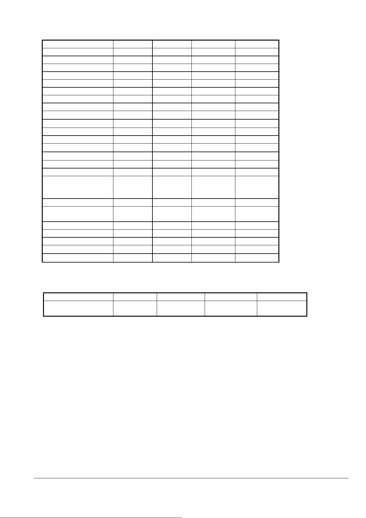
In addition to the standard plain paper and envelope sizes, EPSON provides special paper types in the following sizes:
2.1. Paper Sizes for these printers
2.1.1 Paper Types
Paper Type Size US EUR/Asia Japan
普通紙(JPN)
Plain paper(Others)
Bright White Paper(US) Cut sheets Letter YES NO NO
両面上質普通紙<再生紙
>(JPN)
Bright White Ink Jet
Paper(EUR/Asia)
写真用紙<光沢>(JPN)
Premium Photo Paper
Glossy(US)
Premium Glossy Photo
Paper(EUR/Asia)
フォトマット紙(JPN)
Premium Presentation Paper
Matte(US)
Cut sheets Legal YES
Letter YES
A4 YES YES YES
B5 NO YES YES
A5 NO YES YES
Half-Letter YES NO NO
A6 YES YES YES
User-defined YES YES YES
Cut sheets A4 NO YES YES
Cut sheets Letter YES NO NO
A4 YES YES YES
8x10in.(六切) YES NO YES
5x7in./2L size YES YES YES
NO YES YES
4x6in. YES YES YES
3.5x5in./L size NO NO YES
Cut sheets Letter YES NO NO
A4 YES YES YES
8x10in.(六切) YES NO NO
Matte Paper
スーパーファイン紙(JPN)
Presentation Paper
Matte(US)
Photo Quality Ink Jet
Paper(EUR/Asia)
スーパーファイン専用紙ハ
ガキ(JPN)
スーパーファイン専用ラベル
シート(JPN)
Sheets(US)
Sheets(EUR/Asia)
往復ハガキ(JPN) Post card Double Postcard NO NO YES
郵便ハガキ(JPN) Post card Postcard NO NO YES
郵便 IJ ハガキ
国内封筒
Post card Postcard NO NO YES
Envelope(US)
Envelope(EUR/Asia)
Cut sheets Letter YES NO NO
A4 YES YES YES
Post Card Postcard NO NO YES
Cut Sheets A4 NO NO YES
Envelope Japanese CHOKEI 3
Envelope
Japanese CHOKEI 4
Envelope
Japanese YOKEI 1 Envelope NO NO YES
Japanese YOKEI 3 Envelope NO NO YES
Japanese YOKEI 4 Envelope NO NO YES
Envelope #10 (Portrait) YES YES NO
Envelope DL (Portrait)
Envelope C6 /
Japanese YOKEI 2 Envelope
(Portrait)
NO NO YES
NO NO YES
NO YES NO
NO YES YES
2016/09/02
Revision: 1 Page: 6
Page 7
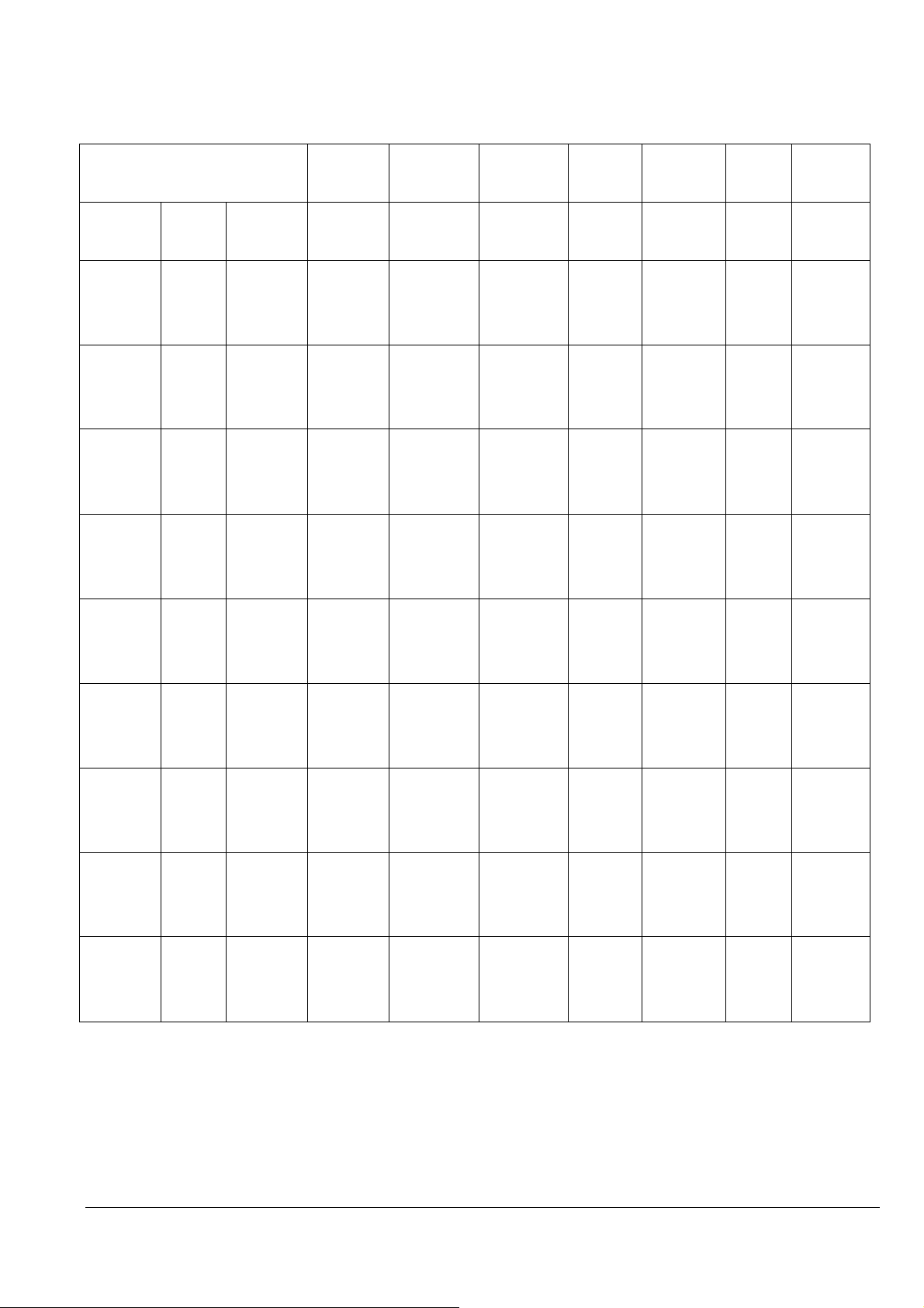
2.2. Paper Size and Orientation
Orientation
Paper Type Dimensions
W x L
A4 210 mm x 297 mm Yes No
A5 148 mm x 210 mm Yes No
A6 105 mm x 148 mm Yes No
B5 182 mm x 257 mm Yes No
Legal 8.5in. x 14in. Yes No
Letter 8.5in. x 11in. Yes No
8x10in.(六切) 203mm x 254mm Yes No
Half Letter 5.5 in. x 8.5 in. Yes No
5in. x8in. 5 in. x 8 in. Yes No
5x7in. / 2L size 127x178 mm Yes No
4 x 6 in. 113.6 mm x 164.4 mm*1) Yes No
3.5x5in. / L size 89 x 127 mm Yes No
16:9 wide 102mm x152mm Yes No
Postcard
Double Postcard
Envelope #10 9.5 in. x 4 .125 in. Yes No
Envelope DL 220 mm x 110 mm Yes No
Envelope C4 /
Japanese KAKUGATA 20 Envelope
Japanese YOKEI 1 Envelope 120mm x 176mm Yes No
Envelope C6 /
Japanese YOKEI 2 Envelope
Japanese YOKEI 3 Envelope 98mm x 148mm Yes No
Japanese YOKEI 4 Envelope 105mm x 235mm Yes No
Japanese CHOKEI 3 Envelope 120mm x 235mm *2) Yes *3) No
Japanese CHOKEI 4 Envelope 90mm x 205mm *2) Yes *3) No
User-defined
89 to 215.9 mm x 127 to 1117.6 mm
100 mmx148 mm Yes No
200 mmx148 mm No Yes
229 mm x 324 mm Yes No
162 mm x 114 mm Yes No
(3.5 in. to 8.5 in. x 5 in. to 44 in.)
↓
Yes No
↓
1) Each of the predetermined sizes is inserted only in the orientation indicated by "Yes" in the above table.
2) Dimension indicates body size without flap.
3) Loading envelope, flap edge first, with printable side up.
2016/09/02
Revision: 1 Page: 7
Page 8

2.3. Printable Area
For the purpose of printing, a sheet of paper is divided into two regions: the printable area and the non-printable
area. These areas are defined as follows.
The printable area is the region within which the printing position can be set, and is the portion which is surrounded
by the left margin position, the right margin position, the top margin position, and the bottom margin position.
The non-printable area is the region in which the printing position cannot be set, except for the right margin position,
and is the region on the paper outside the printable area.
The margins, which determine the printable area, are defined as follows.
The left margin determines the non-printable strip appended to the left side of the printable area. The left margin
position, which defines the margin boundary, is set upon the X axis. Moreover, the left margin position is
considered as being included in the printable area.
The right margin determines the non-printable strip appended to the right side of the printable area. The right
margin position, which defines the margin boundary, is set upon the X axis. Moreover, the right margin position is
considered as being included in the non-printable area. However, it is possible to set the printing position to the
right margin position.
The top margin determines the non-printable strip appended to the upper side of the printable area. The top margin
position, which defines the margin boundary, is set upon the Y axis. Moreover, the top margin position is
considered as being included in the printable area.
The bottom margin determines the non-printable strip appended to the lower side of the printable area. The bottom
margin position, which defines the margin boundary, is set upon the Y axis. Moreover, the bottom margin position
is considered as being included in the printable area.
The page management X-Y discrete coordinate system (hereinafter abbreviated as the page management coordinate
system) which is used as the reference for setting the position of each of these margins, is the same as the position
management coordinate system, except for the definition of the origin.
The position management coordinate system is the coordinate system for management of the printable area which is
set within the page management coordinate system.
The position management coordinate system is set for each page separately.
The origin of the page management coordinate system is defined as follows.
The origin upon the X axis is set to the minimum printing position. The minimum printing position is the farthest
leftward printing position that can physically be set upon the paper. The minimum printing position depends upon
the horizontal position of the paper when it is inserted.
As for the origin upon the Y axis, for the first page directly after paper insertion, the upper edge of the paper is
defined as the origin. For the second and subsequent pages, a position advanced by the page length from the origin
on the page management coordinate system for the previous page is defined as the origin for the current page.
Since in the case of single sheet paper only one page at a time can be inserted, the upper edge of the paper is always
taken as the origin.
Here, page and page length are defined as follows.
A page means a unit region in the Y direction, which includes within it a single printable area. If the paper that is
inserted is single sheet paper, only one page can be established upon each sheet. If the paper that is inserted is
continuous paper, a plurality of pages can be established upon it.
The page length is the length in the Y direction of the page. If the paper that is inserted is single sheet paper, the
length of the printing region in the Y direction from the top margin position to just before the bottom margin
position is taken as the page length. If the paper that is inserted is continuous paper, the distance from the top
margin position on the present page to the top margin position upon the next page is taken as the page length.
2016/09/02
Revision: 1 Page: 8
Page 9
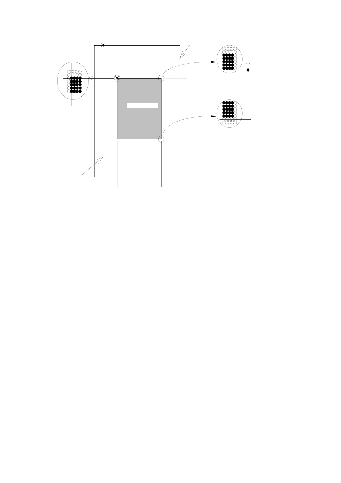
Table 2 Coordinate Systems for a Single Sheet of Paper
argin position
※
Origin of the page management
coordinate system
Paper
Right margin position
Left margin position
Minimum printable position
Left margin position Right margin position
Non-printable area
Top margin
Origin of the position
management coordinate system
L
e
f
t
m
Printable area
a
r
g
i
n
Bottom margin
Non-printable region
R
i
g
h
t
m
a
r
g
i
n
Top margin position
Bottom margin position
Top margin position
Non-printable area
Printable area
Bottom m
2016/09/02
Revision: 1 Page: 9
Page 10
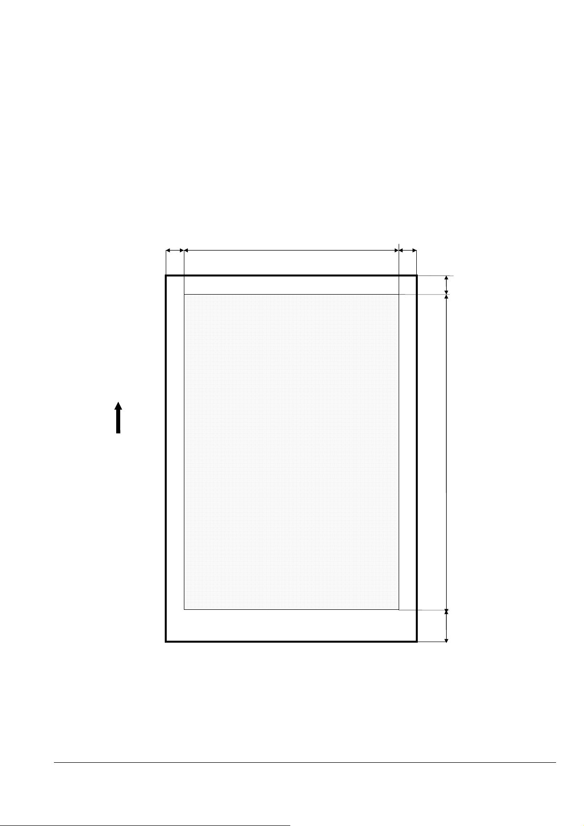
2.3.1 Printing Area (Standard)
Paper feed
D
E
Printing area
Top margin non
-
printable area
margin
F
Ri
ght margin non
-
printable area
The printable areas of various paper sizes on these printers are defined hereafter. Values are expressed in dot units, where 1 dot
= 1/360 inch. As is displayed in the following diagram, printable area can be defined as follows:
A = the width of the unprintable left margin area
A (Centered) = the width of the unprintable left margin area when the printable area is centered
B = the width of the printable area
B (Centered) = the width of the printable area when the printable area is centered
C = the width of the unprintable right margin area
C (Centered) = the width of the unprintable right margin area when the printable area is centered
D = the length of the unprintable top margin area
D (Centered) = the length of the unprintable top margin area when the printable area is centered
E = the length of the printable area
E (Centered) = the length of the printable area when the printable area is centered
Left margin non-printable area
A
C
direction
P
Printing area
※
Bottom
2016/09/02
Revision: 1 Page: 10
non-printable area
Page 11
Standard Sizes
The printing area is specified by A, B, D, and E.
Legal 42/42 2976/2976 42/42 4715/4956
Letter 42/42 2976/2976 42/42 3635/3876
A4 42/42 2892/2892 42/42 3884/4125
A5 42/42 2014/2014 42/42 2651/2892
A6 42/42 1404/1404 42/42 1773/2014
B5 42/42 2496/2496 42/42 3318/3559
Half Letter 42/42 1896/1896 42/42 2735/2976
5x7in. / 2L Size 42/42 1716/1716 42/42 2197/2438
4x6in
3.5x5in. / L Size
8x10in. 42/42 2796/2796 42/42 3275/3516
5x8in. 42/42 1716/1716 42/42 2555/2796
Postcard
Double Postcard
Envelope #10 42/42 1401/1401 42/42 3095/3095
Envelope DL 42/42 1475/1475 42/42 2793/2793
Envelope C4 /
Japanese KAKUGATA 20
Envelope
Japanese YOKEI 1 Envelope
Envelope C6 /
Japanese YOKEI 2 Envelope
Japanese YOKEI 3 Envelope
Japanese YOKEI 4 Envelope
Japanese CHOKEI 3 Envelope
Japanese CHOKEI 4 Envelope
16:9wide
User-defined
With a paper type set by the user, a printing area defined by A, B, D, and E of at least the following number of dots are reserved.
A/A(Expanded) B/B(Expanded) D/D(Expanded) E/E(Expanded)
User-defined
B/B(Expanded) D/D(Expanded) E/E(Expanded)
42/42 1356/1356 42/42 1835/2076
42/42 1177/1177 42/42 1475/1716
42/42 1333/1333 42/42 1773/2014
42/42 2751/2751 42/42 1773/2014
42/42 3162/3162 42/42 3812/4267
42/42 1617/1617 42/42 2169/2410
42/42 1532/1532 42/42 1971/212
42/42 1305/1305 42/42 1773/2014
42/42 1404/1404 42/42 3006/3247
42/42 1617/1617 42/42 3006/3247
42/42 1404/1404 539/42 3006/3247
42/42 1356/1356 42/42 2235/2476
42/42
max. 2976
/ max. 2976
42/42
Unit [1/360inch]
max. 15515
/ max. 15756
2016/09/02
Revision: 1 Page: 11
Page 12
CHAPTER 3: Printing Option
3.1. Printing Quality
These printers have the capability of printing at eleven different levels of quality.
Print density Dot size Raster
command
density
Plain
Paper
Special
Paper
(H x V) (H x V) h / r v / r mH*256
ESC (D
setting
horizontal
ESC (D
setting
vertical
ESC i
setting
+ mL
ESC
(e
setting
n2
Remarks
Fast Eco
Economy
Normal
Fine
Super Fine
Photo
360dpi x
180dpi
360dpi x
180dpi
360dpi x
360dpi
360dpi x
720dpi
720dpi x
720dpi
360dpi x
VSD1 360dpi x
180dpi
2bit
VSD1 360dpi x
180dpi
2bit
VSD1 360dpi x
180dpi
2bit
VSD2 360dpi x
180dpi
2bit
VSD3 360dpi x
180dpi
2bit
VSD2 360dpi x
4/1440 8/1440 Max 60
(Color)/Max
180 (Mono)
4/1440 8/1440 Max 60
(Color)/Max
180 (Mono)
4/1440 8/1440 Max 60
(Color)/Max
180 (Mono)
4/1440 8/1440 Max 60
(Color)/Max
180 (Mono)
4/1440 8/1440 Max 60
(Color)/Max
180 (Mono)
4/1440 8/1440 Max 60 12H Color
11H Color and
Mono
11H Color and
Mono
11H Color and
Mono
12H Color and
Mono
13H Color and
Mono
Draft
Photo 720dpi x
Best
Photo
Photo
RPM
720dpi
720dpi
1440dpi x
720dpi
5760dpi x
1440dpi
180dpi
2bit
VSD2 360dpi x
180dpi
2bit
VSD3 360dpi x
180dpi
2bit
VSD3 360dpi x
180dpi
2bit
only
4/1440 8/1440 Max 60
(Color)/Max
180 (Mono)
4/1440 8/1440 Max 60
(Color)/Max
180 (Mono)
4/1440 8/1440 Max 60 13H Color
12H Color and
Mono
13H Color and
Mono
only
2016/09/02
Revision: 1 Page: 12
Page 13
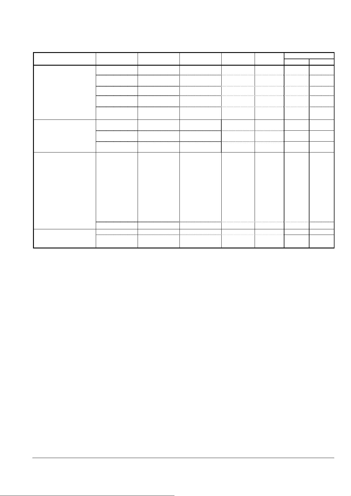
3.2 Recommended Settings for Color and Monochrome Printing
Monochrome or Color printing mode depends on the ESC (K command. See the individual command specifications.
3.2.1 Recommended Setting Modes
Media Preset name Print quality
普通紙(JPN)
Plain paper(Others)
Bright White Paper(US)
両面上質普通紙<再生紙
>(JPN)
Bright White Ink Jet
Paper(EUR/Asia)
写真用紙<光沢>(JPN)
Premium Photo Paper
Glossy(US)
Premium Glossy Photo
Paper(EUR/Asia)
フォトマット紙(JPN)
Premium Presentation Paper
Matte(US)
Matte Paper
Heavy-weight(EUR/Asia)
スーパーファイン紙(JPN)
Presentation Paper Matte(US)
Photo Quality Ink Jet
Paper(EUR/Asia)
Resolution
(dpi)
Draft Fast Economy 360x180 ON VSD1
*Standard Economy 360x360 *ON/OFF VSD1
Normal 360x360 *ON/OFF VSD1
High Fine 360x720 *ON/OFF VSD2
Super Fine 720x720 *ON/OFF VSD3
*Standard Photo 720x720
High Best Photo 1440x720
Photo RPM 5760x1440
*Standard Photo 720x720 *ON/OFF VSD2 52H 53H
Bi-d
*ON/OFF
*ON/OFF
*ON/OFF
Dot
Size
VSD2
VSD2
VSD3
ESC (m
Color Black only
10H 11H
20H 21H
20H 21H
30H 31H
50H 51H
52H -
70H -
A0H -
国内封筒(JPN)
Envelope(US)
Envelope(EUR/Asia)
*Default
High Best Photo 1440x720 *ON/OFF VSD3
*Standard 360x360 ON VSD1 20H 21H
High 360x720 ON VSD2
70H 71H
30H 31H
2016/09/02
Revision: 1 Page: 13
Page 14

CHAPTER 4: COMMAND SEQUENCE
4.1 Raster Graphics Modes
The following two modes are available for raster graphics commands:
1) Non-compressed mode - the print data is transferred without being compressed.
Effective for printing data with a low compression ratio, such as photographs.
2) Run-length encoded mode - the print data is transmitted after run-length encoding compression.
Effective for printing data such as graphs and figures, in which patterns appear repeatedly.
2016/09/02
Revision: 1 Page: 14
Page 15
By raster
4.2 Command Transfer Procedure
4.2.1 Command transfer sequence for non-compressed and the run-length encoded compression modes
The following are the basic commands used in non-compressed and run-length encoded modes. The commands are
listed in order as they are sent:
Table 3 Command Sequence for the Conventional command method of graphics data transmission
Transfer cycle Details of setting Items set Commands used
By document 1.Initialize settings
2. Printing method control 2.1 Turn unidirectional mode on/off
3. Set print format
(single sheet)
By page
5. Transfer data 5.1 Select color ESC (r
5.2 Set horizontal print position ESC(/ or ESC ($
5.3 Print raster graphics: *
5.4 Print compulsory** ESC ACK
6. Printing method control 6.1 Select Monochrome or
6.2 Set Driver Color Mode**** ESC (K
7. Form feed 7.1 Form feed FF
8. Terminate printing 8.1 Initialize printer
*Parameters and data format of non-compressed vs. run-length encoded transmissions will differ with the Print
Raster Graphics command.
**In the case of micro weave print mode, ESC ACK command is inserted only when the plural passes are specified
with no paper feed.
*** It is necessary to send the TI command before the JS command.
4. Set vertical position 4.1 Set vertical print position ESC (V or ESC (v
1.1Exit Packet Mode
1.2 Enter remote mode
Set Printer Timer***
Job Start***
Set Job Name
Paper Feed Setup
Set paper path
Set Media information
Set double paper print
Set user setting
Other Remote Commands
(optional)
Exit Remote Mode
1.3 Initialize printer
1.4 Data Processing Setting
1.5 Select graphics mode
1.6 Set unit
2.2Select Micro-Weave printing
mode
2.3 Select Monochrome or Color
2.4 Set Driver Color Mode
2.5 Select Ink Drop Size
3.1 Set page length
3.2 Set page format
3.3 Set paper dimension
3.4 Set Print method
repeat above for each
color
Color****
8.2 Enter Remote Mode
Load NVR Settings
Job End
Exit Remote Mode
ESC SOH @EJL…
ESC (R
TI
JS
JH
SN
PP
MI
DP
US
ESC 00H 00H 00H
ESC @
ESC (A
ESC (G
ESC (U
ESC U
ESC (i
ESC (K
ESC (K
ESC (e
ESC (C
ESC (c
ESC (S
ESC (m
ESC .
ESC (K
ESC @
ESC (R
LD
JE
ESC 00H 00H 00H
2016/09/02
Revision: 1 Page: 15
Page 16
Table 4 Command Sequence for the newer Method of ESC ( D command method of graphics data transmission
By raster
Transfer cycle Details of setting Items set Commands used
By document 1. Initialize settings
2. Printing method control 2.1 Turn unidirectional mode on/off
3. Set print format
(single sheet)
By page
5. Transfer data 5.1 Set horizontal print position ESC(/ or ESC ($
5.2 Print raster graphics:
5.3 Print compulsory* ESC ACK
6. Printing method control 6.1 Select Monochrome or Color*** ESC (K
6.2 Set Driver Color Mode*** ESC (K
7. Form feed 7.1 Form feed FF
8. Terminate printing 8.1 Initialize printer
*In the case of micro weave print mode, ESC ACK command is inserted only when the plural passes are specified
with no paper feed.
** It is necessary to send the TI command before the JS command.
4. Set vertical position 4.1 Set vertical print position ESC (V or ESC (v
1.1Exit Packet Mode
1.2 Enter remote mode
Set Printer Timer**
Job Start**
Set Job Name
Paper Feed Setup
Set paper path
Set Media information
Set double paper print
Set user setting
Other Remote Commands
(optional)
Exit Remote Mode
1.3 Initialize printer
1.4 Data Processing Setting
1.5 Select graphics mode
1.6 Set unit
2.2 Select Micro-Weave print mode
2.3 Select Monochrome or Color
2.4 Set Driver Color Mode
2.5 Select Ink Drop Size
2.6 Set resolution of Raster mode
3.1 Set page length
3.2 Set page format
3.3Set paper dimension
3.4 Set Print method
repeat above for each color
8.2 Enter Remote Mode
Load NVR Settings
Job End
Exit Remote Mode
ESC SOH @EJL…
ESC (R
TI
JS
JH
SN
PP
MI
DP
US
ESC 00H 00H 00H
ESC @
ESC (A
ESC (G
ESC (U
ESC U
ESC (i
ESC (K
ESC (K
ESC (e
ESC (D
ESC (C
ESC (c
ESC (S
ESC (m
ESC i
ESC @
ESC (R
LD
JE
ESC 00H 00H 00H
2016/09/02
Revision: 1 Page: 16
Page 17

4.3 Limitations of Command Settings
• “Exit Packet Mode”, in many circumstances, command MUST be called before any communication or printing
can occur on any I/F. This command is described in the “Individual Command Specifications”.
• The “Set absolute vertical print position ESC (V” and “Set relative vertical print position ESC (v” commands
will set the starting print position of the subsequent data to be printed, including whatever white space may exist
within that data. To avoid confusion, it is recommended not to embed large null or white space in the data.
• All null raster data should not be sent to the printer.
• For detailed specifications of the commands that are transmitted, refer to CHAPTER 5, "Individual Command
Specifications".
2016/09/02
Revision: 1 Page: 17
Page 18

4.4 Raster Graphics Data Format
The raster graphics commands that are implemented these printers have a very different data format from the
general specification commands. The driver must generate appropriate data taking into account the color nozzle
positions in the printer are uniquely vertically aligned.
The parameters for the raster graphics commands used by these printers are as follows.
1)
ESC i r c b nL nH mL mH
For detail on the specification command that is transmitted, refer to CHAPTER 5, "Individual
Command Specification".
• Horizontal resolution of 360 dpi (ESC (D )
• Vertical resolution of 180 dpi (ESC (D )
• Vertical dot count of 60 dots (color mode) ***
• Vertical dot count of 180 dots (monochrome mode)
Those commands and parameters are only available.
*** Dot size is select variable.
2)
ESC . 0 20 10 m nL nH **
ESC . 1 20 10 m nL nH **
For detail on the specification command that is transmitted, refer to CHAPTER 5, "Individual
Command Specification".
• Horizontal resolution of 360 dpi
• Vertical resolution of 180 dpi
• Vertical number of 60 dots (color mode)
• Vertical number of 180 dots (monochrome mode)
Those commands and parameters are only available.
** This command cannot print color data.
2016/09/02
Revision: 1 Page: 18
Page 19
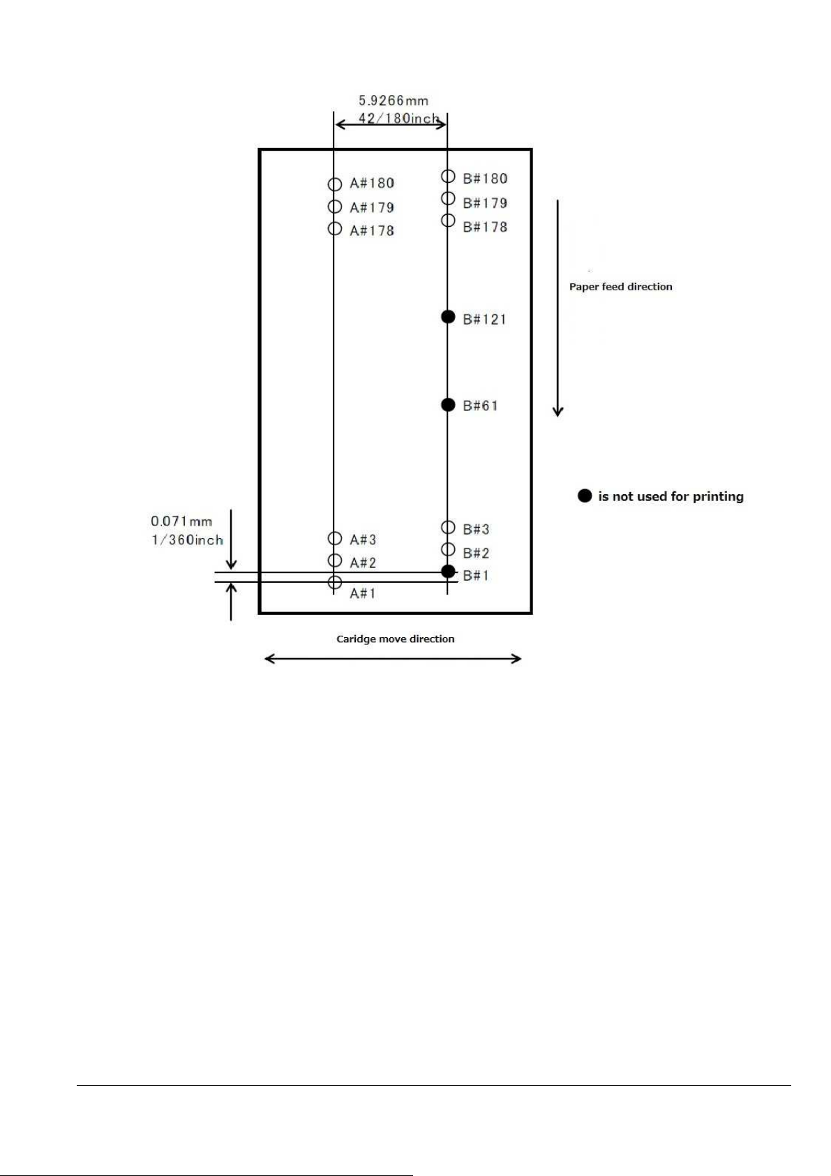
The nozzle constitution and each nozzle name are shown below.
Black : 180 Nozzles (A#1A#180)
Yellow : 59Nozzles (B#2B#60), Magenta : 59Nozzles (B#62#120), Cyan : 59Nozzles (B#122#180)
2016/09/02
Revision: 1 Page: 19
Page 20
α
α
α
α
α
α
α
α
α
α
α
α
α
α
α
α
α
α
α
α
α
α
α
α
α
α
α
α
α
α
α
α
α
α
α
α
α
α
α
α
α
α
α
α
α
α
α
α
α
α
α
α
α
α
α
α
α
α
α
α
α
α
α
α
α
α
α
α
α
α
α
α
α
α
α
α
α
α
α
α
α
α
For monochrome printing, only Black nozzle is used.
For color printing, the Black and Color nozzles are used. The Black nozzle only uses nozzles 121 to 180 and does
not need to send NULL data to other nozzle.
When a user changes the printing modes to print in color or to print in monochrome, use ESC (K command.
When a user wants to print the monochrome data, a user selects the monochrome mode.
When a user wants to print the color data, a user selects the color mode and a user must select a variable dot and
send the variable data.
For these printers, the data must be configured bearing in mind the vertical positions of the nozzles. EPSON printers
are generally having print heads with nozzles for each color structured in the same vertical position, but the head of
these printers takes the Color nozzle as a reference point. When transferring data to the printer, these offsets must be
taken into consideration.
Correspondence table of raster command row and the nozzle are shown below. (Color printing)
Row ("raster")
number
1
2
3
4
5
6
7
8
9
10
… … … … …
51
52
53
54
55
56
57
58
59
60
61 - - … … … … …
180 - - -
Cyan
Vertical position
+120/180inch
+121/180inch
+122/180inch
+123/180inch
+124/180inch
+125/180inch
+126/180inch
+127/180inch
+128/180inch
+129/180inch
+170/180inch
+171/180inch
+172/180inch
+173/180inch
+174/180inch
+175/180inch
+176/180inch
+177/180inch
+178/180inch
+179/180inch
Magenta
Vertical position
+60/180inch
+61/180inch
+62/180inch
+63/180inch
+64/180inch
+65/180inch
+66/180inch
+67/180inch
+68/180inch
+69/180inch
+110/180inch
+111/180inch
+112/180inch
+113/180inch
+114/180inch
+115/180inch
+116/180inch
+117/180inch
+118/180inch
+119/180inch
Yellow
Vertical position
(base position)
+1/180inch
+2/180inch
+3/180inch
+4/180inch
+5/180inch
+6/180inch
+7/180inch
+8/180inch
+9/180inch
+50/180inch
+51/180inch
+52/180inch
+53/180inch
+54/180inch
+55/180inch
+56/180inch
+57/180inch
+58/180inch
+59/180inch
Black
Vertical position
(base position)
+1/180inch
+2/180inch
+3/180inch
+4/180inch
+5/180inch
+6/180inch
+7/180inch
+8/180inch
+9/180inch
+50/180inch
+51/180inch
+52/180inch
+53/180inch
+54/180inch
+55/180inch
+56/180inch
+57/180inch
+58/180inch
+59/180inch
+60/180inch
+179/180inch
2016/09/02
Revision: 1 Page: 20
Page 21

Command transmission
Command transmission example and printing result of easy ESC/P Raster data are the following.
ESC @ initialization
ESC (G 01 00 01
ESC (U 01 00 14 Set unit (1/180 inch)
ESC (e 02 00 00 10 Select dot size(variable1)
ESC (D 04 00 A0 05 08 04 Set resolution of Raster mode (180 x 360 DPI)
ESC i 00 00 02 08 00 01 00 FF FF FF FF FF FF FF FF A: Black 1line
CR carriage return
ESC (v 02 00 01 00 relative vertical print position (1/180 inch)
ESC i 02 00 02 08 00 01 00 FF FF FF FF FF FF FF FF B: Cyan 1line
CR carriage return
ESC (v 02 00 01 00 relative vertical print position (1/180 inch)
ESC i 01 00 02 08 00 01 00 FF FF FF FF FF FF FF FF C: Magenta 1line
CR carriage return
ESC (v 02 00 01 00 relative vertical print position (1/180 inch)
ESC i 04 00 02 08 00 01 00 FF FF FF FF FF FF FF FF D: Yellow 1line
CR carriage return
ESC (v 02 00 01 00 relative vertical print position (1/180 inch)
ESC i 00 00 02 08 00 01 00 FF FF FF FF FF FF FF FF E: Black 1line
CR carriage return
ESC (v 02 00 01 00 relative v print position (1/180 inch)
0Ch paper eject
ESC @ initialization
2016/09/02
Revision: 1 Page: 21
Page 22
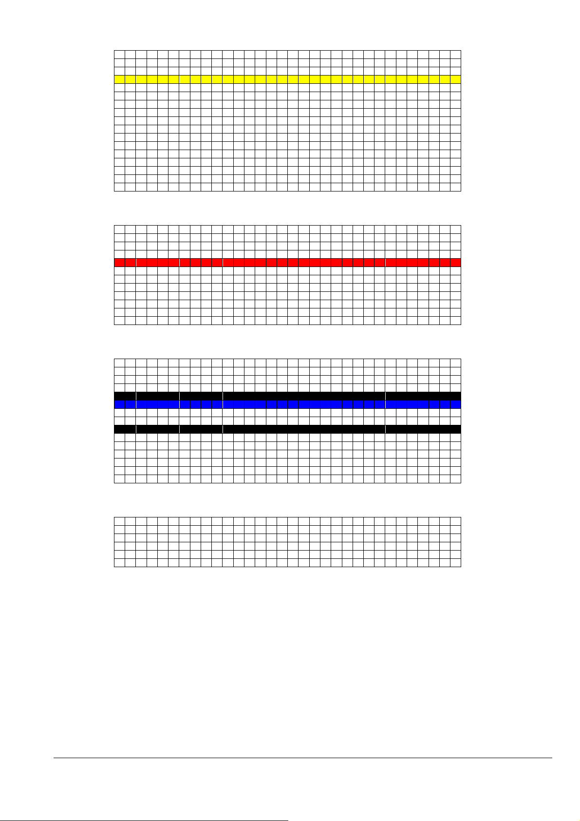
Print result.
(BaseLine)
+1/180”
+2/180”
D:Yellow
+3/180”
+4/180”
+5/180”
+6/180”
+7/180”
+8/180”
+9/180”
+10/180”
+11/180”
+12/180”
+13/180”
+14/180”
+15/180”
+16/180”
+58/180”
+59/180”
+60/180”
+61/180”
C:Magenta
+62/180”
+63/180”
+64/180”
+65/180”
+66/180”
+67/180”
+68/180”
+69/180”
+116/180”
+117/180”
+118/180”
+119/180”
A:Black
+120/180”
B:Cyan
+121/180”
+122/180”
+123/180”
E:Black
+124/180”
+125/180”
+126/180”
+127/180”
+128/180”
+129/180”
+
130/180”
+174/180”
+175/180”
+176/180”
+177/180”
+
178/180”
+
179/180”
… …
… …
… …
… …
… …
… …
2016/09/02
Revision: 1 Page: 22
Page 23

CHAPTER 5: INDIVIDUAL COMMAND SPECIFICATIONS
5.1.1 Exit Packet Mode
00H 00H 00H ESC 01H “@EJL” 20H “1284.4” 0AH “@EJL” 20H 20H 20H 20H 20H 0AH Ver 1.00
[Name] EPSON packet mode exit command (special command) [Setting]
[Format] 00H,00H,00H,1BH,01H,40H,45H,4AH,4CH,20H,31H,32H,38H,34H,2EH,34H,0AH,
40H,45H4AH,4CH,20H,20H,20H,20H,20H,0AH
[Range of Definition] --[Function] 1) If the system is in packet mode, this command must be sent before any other commands can
be successfully transferred over either USB or Parallel Port, including the basic ESC @
printer initialization command.
2) Packet communication protocol (EPSON packet mode) is cancelled.
The command for entering packet mode and the commands utilized in packet mode are
EPSON proprietary.
[Initial State] The initial state of the printer, unused and unopened, new from the EPSON box, may or may
not be in packet mode. However, once the printer has received any print job from any
other source (especially a Windows OS printer driver) it will most likely be in packet mode.
If the printer is in EPSON packet mode; no typical USB and possibly Parallel Port
transmissions can be received or recognized.
[Related Commands] ---
2016/09/02
Revision: 1 Page: 23
Page 24

5.1.2 Initialize printer ESC @
ESC @ Ver 1.00
[Name] Initialize printer [Setting]
[Format] 1BH, 40H
[Range of Definition] [Function] 1) The various settings are returned to their initial values.
2) The Y axis origin of the page management coordinate system and the position management
coordinate system are set to the current printing position on the Y axis.
3) The present printing position on the X axis is set to the origin upon the X axis.
4) Text mode printing is selected.
[Initial State] [Related Commands]
[Setting] Commands whose settings are affected by this command.
The settings for all commands are returned to their initial states.
[Setting] Commands that change the effects of this command.
None
[Operation] Commands whose functionality is affected by this command.
None
[Operation] Commands that change the effects of this command.
None
2016/09/02
Revision: 1 Page: 24
Page 25

5.1.3 Line feed LF
LF Ver. 1.00
[Name] Line feed [Operation]
[Format] 0AH
[Range of Definition] [Function] 1) Advances the current printing position in the positive Y direction by an amount equal to the
current line separation amount. Sets the printing position in the X direction to the starting
point (the left margin position) on the X axis of the position management coordinate
system.
2) If this command sets the Y direction printing position into the non-printable area, then the
page is ejected. The position management coordinate system is set to the next page. In
addition the printing position is set to the origin of the position management coordinate
system for the new page.
[Initial State] [Related Commands]
Related Command [Setting]s that apply an effect.
None
Related Command [Setting]s that receive an effect.
None
Related Command [Operation]s that apply an effect.
None
Related Commands [Operation]s that receive an effect.
The amount of advancement per line is set by the ESC + command.
The non-printable area is set by the ESC (c command.
The amount of advancement per line, the non-printable area, and the left margin position
are reset to their initial state by the ESC @ and ESC (G commands.
2016/09/02
Revision: 1 Page: 25
Page 26

5.1.4 Form feed FF
FF Ver 1.00
[Name] Form feed [Operation]
[Format] 0CH
[Range of Definition] [Function] 1) The contents of the print buffer are printed. The current page is ejected. The position
management coordinate system is set to the next page. The printing position is set to the
origin of the position management coordinate system for the new page.
2) This command is ignored if the printer is out of paper.
[Initial State] -
[Related Commands]
[Setting] Commands whose settings are affected by this command.
None
[Setting] Commands that change the effects of this command.
None
[Operation] Commands whose functionality is affected by this command.
None
[Operation] Commands that change the effects of this command.
The page length is set by the ESC (C command.
The page length and the left margin position are reset to their initial states by the ESC @
and ESC (G commands.
2016/09/02
Revision: 1 Page: 26
Page 27

5.1.5 Carriage Return CR
CR Ver 1.00
[Name] Carriage Return [Operation]
[Format] 0DH
[Range of Definition] [Function] 1) The printing position in the X direction is set to the origin (the left margin) on the X axis of
the position management coordinate system.
[Initial State] [Related Commands]
[Setting] Commands whose settings are affected by this command.
None
[Setting] Commands that change the effects of this command.
None
[Operation] Commands whose functionality is affected by this command.
None
[Operation] Commands that change the effects of this command.
None
2016/09/02
Revision: 1 Page: 27
Page 28

5.1.6 Control paper loading/ejecting ESC EM n
ESC EM n Ver 1.00
[Name] Control paper loading/ejecting [Setting]
[Format] 1BH, 19H, n
[Range of Definition] n=52H
(="1", "R")
[Function] 1) The CSF (cut sheet feeder) receives the following commands, according to the value of n:
n=52H eject paper
2) If n has any value other than the above, this command is ignored.
3) The ESC EM “R” will only eject paper fed from the CSF. If the paper being fed was not
fed by the CSF, this command is ignored.
4) Bin selection settings apply to the next and subsequent paper feedings.
5) After the ESC EM “R” command ejects the paper, the printing position in the X direction is
set to the origin on the X axis.
[Initial State] -
[Related Commands]
[Setting] Commands whose settings are affected by this command.
None
[Setting] Commands that change the effects of this command.
Bin selection is reset to its initial state by the ESC @ command.
[Operation] Commands whose functionality is affected by this command.
None
[Operation] Commands that change the effects of this command.
None
2016/09/02
Revision: 1 Page: 28
Page 29

5.1.7 Set absolute horizontal print position ESC $ nL nH
ESC $ nL nH Ver 1.00
[Name] Set absolute horizontal print position [Operation]
[Format] 1BH, 24H, nL, nH
[Range of Definition] 0 ≤ nL ≤ 255
0 ≤ nH ≤ 127
[Function] 1) The printing position in the positive X direction is set to:
0 <= (256 x nH + nL) x 2880 <= 209.973 mm
(absolute horizontal position setting value)
OR
0 <= (256 x nH + nL) x 2880 <= 23808 inch
(absolute horizontal position setting value) 2880
from the origin (the left margin position) on the X axis of the position management coordinate
system.
2) If (current left margin position)+((256 x nH + nL) x (absolute horizontal position setting
value)) is passed the right margin position, then this command is ignored.
[Initial State] -
[Related Commands]
[Setting] Commands whose settings are affected by this command.
None
[Setting] Commands that change the effects of this command.
None
[Operation] Commands whose functionality is affected by this command.
None
[Operation] Commands that change the effects of this command.
The “absolute horizontal position setting value” is set by the ESC (U command.
The “absolute horizontal position setting value” is restored to its initial state by the ESC @
and ESC (G commands.
The printer settings are restored to their initial state to by the ESC @ command.
2016/09/02
Revision: 1 Page: 29
Page 30

5.1.8 Set absolute horizontal print position ESC ( $ nL nH m1 m2 m3 m4
ESC ( $ nL nH m1 m2 m3 m4 Ver 1.00
[Name] Set absolute horizontal print position [Operation]
[Format] 1BH, 28H, 24H, nL, nH, m1, m2, m3, m4
[Range of Definition] nL=04H, nH=00H
0 <= ( m4 * 1000000H + m3 * 10000H + m2 * 100H + m1 ) * 2880 <= 209.973 mm
(absolute horizontal position setting value )
OR
0 <= ( m4 * 1000000H + m3 * 10000H + m2 * 100H + m1 ) * 2880 <= 23808 inch
(absolute horizontal position setting value) 2880
[Function] 1) The printing position in the X direction is set to the following positive value from the origin
(left margin position) on the X axis of the position management coordinate system:
((m4×2563 +m3×2562 + m2×256 + m1) x (absolute horizontal position setting value)
2) If Left margin +(((m4×2563+m3×2562+m2×256+m1) x (absolute horizontal position
setting value)) is beyond the right margin position, then this command is ignored.
3) This Command is only effective in graphics mode.
[Initial State] -
[Related Commands]
[Setting] Commands whose settings are affected by this command.
None
[Setting] Commands that change the effects of this command.
None
[Operation] Commands whose functionality is affected by this command.
None
[Operation] Commands that change the effects of this command.
The absolute horizontal position setting units are set by the ESC (U command.
The absolute horizontal position setting units are reset to their initial state by the ESC @
and ESC (G commands.
The absolute horizontal print position is restored to its initial, default setting by the ESC @
command.
2016/09/02
Revision: 1 Page: 30
Page 31

5.1.9 Set page length in defined unit (extended) ESC (C nL nH m1 m2 m3 m4
ESC (C nL nH m1 m2 m3 m4 Ver 2.00
[Name] Set page length in defined unit(extended) [Operation]
[Format] 1BH, 28H, 43H, nL, nH, m1, m2, m3, m4
[Range of Definition] nL=04H, nH=00H
0<=(m4*1000000H+m3*10000H+m2*100H+m1) *1440/(defined value) <=1FFFFFFFH
[Function] 1) The page length is set to ((mH x 256) + mL) x (page management value) *25.4mm.
2) If the formula applied values of mH and mL produces a value outside the Range of
Definition, this command is ignored.
3) The Y axis origin of the page management coordinate systems and position management
coordinate systems are set to the current Y direction printing position. The origin on the X
axis is not changed at this time.
4) The top margin position is set to the origin on the Y axis. The bottom margin position is
set to the position positive Y page length from the top margin.
[Initial State] The page length is set to 558.8mm(22 inches).
[Related Commands]
[Setting] Commands whose settings are affected by this command.
The top and bottom margin position settings set by the ESC (c commands are cleared.
[Setting] Commands that change the effects of this command.
The page length, the page management value, and the top and bottom margin positions are
reset to their initial states by the ESC @ and ESC (G commands.
[Operation] Commands whose functionality is affected by this command.
New page processing by the FF command is affected (the amount of movement is
changed).
New lines generated by the LF command that go outside the printable area are affected.
Processing by the ESC (v command is affected.
Processing by the ESC (V command is affected.
[Operation] Commands that change the effects of this command.
The page management value is set by the ESC (U command.
2016/09/02
Revision: 1 Page: 31
Page 32

5.1.10 Select graphics mode ESC (G nL nH m
ESC (G nL nH m Ver 1.00
[Name] Select graphics mode [Operation]
[Format] 1BH, 28H, 47H, nL, nH, m
[Range of Definition] nL=01H, nH=00H
m=01H or 31H
[Function] 1) Shifts to graphics mode.
2) If m has any value other than the above, this command is ignored.
3) Printing of lines up to the present line is started, and the printer waits until the printing is
completed.
4) The various settings are the same as when the power is turned on.
5) The page management coordinate system and the position management coordinate system
are set by taking the printing position in the Y direction at the time of setting as the origin
on the Y axis.
6) The printing position in the X direction is set to the origin upon the X axis.
7) The microweave printing mode selection command becomes effective.
[Initial State] Character mode.
[Related Commands]
[Setting] Commands whose settings are affected by this command.
Default character mode selection made by the ESC @ command is changed.
[Setting] Commands that change the effects of this command.
The graphics mode is cancelled by the ESC @ command.
[Operation] Commands whose functionality is affected by this command.
In graphics mode, only the following commands are valid:
LF ESC (C
FF ESC ( \
CR ESC (U
ESC EM ESC (V
ESC. ESC (r
ESC + ESC (v
ESC @ ESC \
ESC (c ESC $
ESC (i ESC r
ESC (K ESC U
ESC ( e
[Operation] Commands that change the effects of this command.
None
2016/09/02
Revision: 1 Page: 32
Page 33

5.1.11 Set unit (extended) ESC (U nL nH P V H mL mH
ESC (U nL nH P V H mL mH Ver 2.00
[Name] Set unit(extended) [Setting]
[Format] 1BH, 28H, 55H, nL, nH, P, V, H, mL mH
[Range of Definition] nL=05H, nH=00H
P=( mH*256 + mL ) = 90, 120, 180, 360, 720, 1440, 2880
V=( mH*256 + mL ) = 120, 180, 360, 720, 1440, 2880, 5760
H=( mH*256 + mL ) = 90, 180, 360, 720, 1440, 2880, 5760
[Function] 1) Set the following standard values in units of b / ( mH * 256 + mL ) * 25.4mm :
The H parameter determines the horizontal position setting units
The V parameter determines the vertical position setting units
The P parameter determines the page management units
2) This Command is only effective in graphics mode.
[Initial State] Page management value: 0.071mm(1/360 inch)
Relative horizontal position setting value: 0.141mm(1/180 inch) units
Absolute horizontal position setting value: 0.423mm(1/60 inch) units
Relative vertical position setting value: 0.071mm(1/360 inch) units
Absolute vertical position setting value: 0.071mm(1/360 inch) units
[Related Commands]
[Setting] Commands whose settings are affected by this command.
None
[Setting] Commands that change the effects of this command.
None
[Operation] Commands whose functionality is affected by this command.
The relative horizontal position setting value used by the ESC \ and ESC( / commands is set.
The absolute horizontal position setting value used by the ESC $ and ESC( $ commands is set.
The relative vertical position setting value used by the ESC (v command is set.
The absolute vertical position setting value used the ESC (V command is set.
The unit page length specification value used by the ESC (C command is set.
The page format specification value used by the ESC (c command is set.
The paper dimension specification value used by the ESC (S command is set.
[Operation] Commands that change the effects of this command.
The printer settings are restored to their initial state to by the ESC @ command.
2016/09/02
Revision: 1 Page: 33
Page 34

5.1.12 Set absolute vertical print position (extended) ESC (V nL nH m1 m2 m3 m4
ESC (V nL nH m1 m2 m3 m4 Ver 2.00
[Name] Set absolute vertical print position(extended) [Operation]
[Format] 1BH, 28H, 56H, nL, nH, m1, m2, m3, m4
[Range of Definition] nL=04H, nH=00H
(Vertical position set) = (mL + mH x 256) x (units set)
0 <= (m4*1000000H+ m3*10000H+m2*100H+m1)×1440 <= 1FFFFFFFH
(absolute vertical print position value)
[Function] 1) The printing position in the Y direction is set to a position spaced in the positive direction
by (m4*256*256*256 +m3*256*256 + m2*256 + m1) x (absolute vertical print position
value) from the Y axis of the position management coordinate system.
2) If the printing position in the Y direction has been set by this command to a non-printable
area, then the paper is ejected. The position management coordinate system is set to the
next page. In addition, the printing position in the Y direction is reset to the origin upon the
Y axis of the new position management coordinate system.
3) Settings made in the negative direction are ignored.
[Initial State] [Related Commands]
[Setting] Commands whose settings are affected by this command.
None
[Setting] Commands that change the effects of this command.
None
[Operation] Commands whose functionality is affected by this command.
None
[Operation] Commands that change the effects of this command.
The absolute vertical position value is set by the ESC( U commands.
The range of unprintable areas are set by the ESC( c, ESC N and ESC O commands.
The relative vertical position setting value, the non-printable area and the printing position in the
Y direction are reset to their initial states by the ESC @ and ESC (G commands.
2016/09/02
Revision: 1 Page: 34
Page 35

5.1.13 Set page format (extended) ESC (c nL nH t1 t2 t3 t4 b1 b2 b3 b4
ESC (c nL nH t1 t2 t3 t4 b1 b2 b3 b4 Ver 2.00
[Name] Set page format(extended) [Setting]
[Format] 1BH, 28H, 63H, nL, nH, t1, t2, t3, t4, b1, b2, b3, b4
[Range of Definition] nL=08H, nH =00H
0<t1,t2,t3,t4,b1,b2,b3,b4<=255
0 <= ( t4*1000000H + t3*10000H + t2*100H + t1 )*1440 <= 1FFFFFFFH
(defined unit)
0 <= ( b4*1000000H + b3*10000H + b2*100H + b1 )*1440 <= 1FFFFFFFH
(defined unit)
( t4*1000000H + t3*10000H + t2*100H + t1 ) < ( b4*1000000H + b3*10000H + b2*100H +
b1 )
[Function] 1) The origin on the Y axis of the position management coordinate system is set to:
+ (t4*256*256*256 + t3*256*256 + t2*256 + t1) x (defined unit)
from the origin on the Y axis of the page management coordinate system.
The bottom margin is set at a position spaced in the positive direction to:
(b4*256*256*256 + b3*256*256 + b2*256 + b1) x (defined unit)
from the origin on the Y axis of the position management coordinate system.
2) The printing position in the Y direction is shifted to the origin of the position management
coordinate system. At this time, the origin on the X axis is not changed.
3) If the distance from the origin on the Y axis of the position management coordinate system
to the bottom margin position is greater than the page length, then this distance from the
origin on the Y axis to the bottom margin position is set as the new page length.
4) If the paper inserted for printing is cut sheet paper, then the distance from the top margin
position to the bottom margin position is set as the page length.
5) This command is only effective in graphics mode.
[Initial State] The top margin position is set to 8.382mm(0.33 inches) .
The bottom margin position is set to the page length.
The page length is set to 558.8mm(22 inches).
[Related Commands]
[Setting] Commands whose settings are affected by this command.
The set page length is changed by the ESC (C command.
[Setting] Commands that change the effects of this command.
The top margin and the bottom margin are set by the ESC commands.
The page length and the bottom margin position are returned to their initial states by the
ESC @ and the ESC (G commands.
[Operation] Commands whose functionality is affected by this command.
New page processing by the FF command is affected (the amount of movement is
changed).
New lines generated by the LF command which go outside the printable area are affected.
Processing by the ESC (v command is affected.
Processing by the ESC (V command is affected.
[Operation] Commands that change the effects of this command.
The page management units are set by the ESC (U command.
2016/09/02
Revision: 1 Page: 35
Page 36

5.1.14 Monochrome Mode / Color Mode Selection ESC ( K nL nH m n
ESC ( K nL nH m n Ver 2.00
[Name] Monochrome Mode / Color Mode Selection [setting]
[Format] 1BH, 28H, 4BH, nL, nH, m, n
[Range of Definition] nL=02H, nH=00H
m=00H, 01H, 02H
n=00H, 01H, 02H
nH is MSB mask.
[Function] In the case of “m=00H”,
1) Monochrome mode or color mode is selected.
n=00H: Default mode
n=01H: Monochrome mode(Pure Black)
n=02H: Color mode(Composite Black or Color)
2) When monochrome mode is selected, the color selection commands ESC r and ESC (r are
ignored. Furthermore, the results of color raster commands which have been dispatched
in monochrome mode are unpredictable.
3) If n has any value other than the above, this command is ignored.
4) If BK printing warning, The State becomes print-impossible.
In the case of “m=01H”,
The processing at the BK printing mode is controlled according to the value of ‘n’.
1) n=00H: Not BK printing mode
In the case of “m=02H”,
Monochrome mode or color mode on each page are selected according to the value of ‘n’.
n=00H: Color mode
n=01H: Grayscale mode(Pure black or Composite Black mode)
n=02H: Color mode
[Initial State] Default mode.
[Supplementary Note] Higher throughput speeds may be obtained for printing monochrome data when monochrome
mode is selected rather than color mode. For printing in color, the color mode must be
selected.
[Related Commands]
[Setting] Commands whose settings are affected by this command.
When monochrome mode is selected, color setting modes using the ESC r and ESC (r
commands are ignored.
[Setting] Commands that change the effects of this command.
The default mode is selected by the ESC @ command.
[Operation] Commands whose functionality is affected by this command.
None.
[Operation] Commands that change the effects of this command.
None.
2016/09/02
Revision: 1 Page: 36
Page 37

5.1.15 Select MicroWeave printing mode ESC (i
ESC (i Ver 1.00
[Name] Select MicroWeave printing mode [Operation]
[Format] 1BH, 28H, 69H, 01H, 00H, n
[Range of Definition] n=00H, 01H, 30H, 31H
[Function] 1) Selects / deselects the MicroWeave mode.
all parameters : deselects
[Initial State] Non-MicroWeave mode
[Related Commands]
[Setting] Commands whose settings are affected by this command.
This command changes the non-selected state set by either the ESC (G or ESC @
commands.
[Setting] Commands that change the effects of this command.
The ESC (G command sets the non-selected state.
The ESC @ command sets the non-selected state.
[Operation] Commands whose functionality is affected by this command.
None
[Operation] Commands that change the effects of this command.
None
2016/09/02
Revision: 1 Page: 37
Page 38

5.1.16 Selects dot size ESC (e nL nH m d
ESC (e nL nH m d Ver 1.00
[Name] Selects dot size [Setting]
[Format] 1BH, 28H, 65H, nL, nH, m, d
[Range of Definition] nL=02H, nH=00H
m=00H, d=00H, 11H, 12H, 13H
[Function] 1) The dot size is set according to the value of d.
2) The d parameter has the following meaning:
d=00H: VSD1 1bit (for DOS)
d=11H: VSD1 2bit
d=12H: VSD2 2bit
d=13H: VSD3 2bit
3) Default dot sizes are specific to each printer model.
4) Dot control is valid irrespective of printing mode or printing density.
5) If the dot size is changed part way through a page, the results are unpredictable.
6) If n has any value other than the above, this command is ignored.
[Initial State] Default
[Related Commands]
[Setting] Commands whose settings are affected by this command.
Use of the ESC . command requires this command to be sent as follows: ESC ( e 2 0 0 0
[Setting] Commands that change the effects of this command.
Default dot size is automatically selected by the ESC @ or ESC (G commands.
[Operation] Commands whose functionality is affected by this command.
None
[Operation] Commands that change the effects of this command.
None
2016/09/02
Revision: 1 Page: 38
Page 39

5.1.17 Select color ESC (r nL nH m n
ESC (r nL nH m n Ver 1.00
[Name] Select color [Setting]
[Format] 1BH, 28H, 72H, nL, nH, m, n
[Range of Definition] nL=02H, nH=00H
m=00H, 01H
n=00H, 01H, 02H, 04H
[Function] 1) The print color is selected according to the values of m and n.
m N Print color
00H 00H Black
00H 01H Magenta
00H 02H Cyan
00H 04H Yellow
2) If either m or n has a value other than those above, this command is ignored.
3) This command is only effective in graphics mode.
[Initial State] Black is selected.
[Related Commands]
[Setting] Commands whose settings are affected by this command.
None
[Setting] Commands that change the effects of this command.
The ESC @ command selects black.
[Operation] Commands whose functionality is affected by this command.
None
[Operation] Commands that change the effects of this command.
The ESC (G command puts the printer in graphics mode.
2016/09/02
Revision: 1 Page: 39
Page 40

5.1.18 Set relative vertical print position (extended) ESC (v nL nH m1 m2 m3 m4
ESC (v nL nH m1 m2 m3 m4 Ver 2.00
[Name] Set relative vertical print position(extended) [Setting]
[Format] 1BH, 28H, 76H, nL, nH, m1, m2, m3, m4
[Range of Definition] nL=04H, nH=00H
0 <= (m4*1000000H +m3*10000H + m2*10H + m1))×1440 <= 1FFFFFFFH
(relative vertical print position value)
[Function] 1) The printing position in the Y direction is set to positive:
(m4*256*256*256 + m3*256*256 + m2*256 + m1) x (relative vertical print position
value)
from the present Y printing position.
2) If the position set by this command is higher than the top margin position on the current
page, this command is ignored.
3) If the Y direction printing position set by this command extends to a non-printable area,
then the position management coordinate system is set to the next page; and the printing
position in the Y direction is reset to the origin on the Y axis of the new position
management coordinate system.
[Initial State] [Related Commands]
[Setting] Commands whose settings are affected by this command.
None
[Setting] Commands that change the effects of this command.
None
[Operation] Commands whose functionality is affected by this command.
None
[Operation] Commands that change the effects of this command.
The relative vertical position setting value is set by the ESC (U command.
The non-printable area is set by the ESC (c commands.
The relative vertical position setting value, the non-printable area, and the printing position
in the Y direction are reset to their initial states by the ESC @ and ESC (G commands.
2016/09/02
Revision: 1 Page: 40
Page 41

5.1.19 Print raster graphics ESC . c v h m nL nH d1...dk (c=0,1)
256*nH+nL dots
int((256*nH+nL+7)/8) bytes
m
ESC . c v h m nL nH d1...dk (c=0,1) Ver 1.00
[Name] Print raster graphics [Operation]
[Format] 1BH, 2EH, c, v, h m, nL, nH, d1...dk
[Range of Definition] c=0, 1, 2 (a description of the behavior of this function when c == 2 is in the next section)
v=10 (v/3600 dpi)
h=10 (h/3600 dpi)
0 ≤ nL ≤ 255
0 ≤ nH ≤ 127
0 ≤ d ≤ 255
m=1, 8, 24, (color mode)
[Function] This function prints raster graphics at
c style compression, with
y /3600 dpi vertical density, and
h /3600 dpi horizontal density, to print out
m raster lines, or scan lines, or rows of dots in the vertical direction, covering
(nH * 256) + nL total dots, using
k subsequent bytes of data.
1) If c has any value other than those specified above, this command terminates at the instant
that c is processed.
If either v or h has any value other than the above, this command is ignored.
2) The actual image pattern is generated according to a raster method determined by the
following parameters:
c: printing mode
00H: full graphics mode (non-compressed mode)
01H: run-length encoded compression mode
02H: TIFF compression mode
If TIFF compression mode is used, then m must be
equal to 1.
Explanation of this function where c == 2 is in the
next section
v: printing density in the vertical direction v/3600 (dpi)
h: printing density in the horizontal direction h/3600 (dpi)
m: number of dots (rows) in the vertical direction, number of raster or
scan lines
nL, nH: number of dots covered in the horizontal direction =
((256 x nH) + nL)
k: number of items of data = m x int((nH x 256 + nL + 7)/8) for
uncompressed data
= undeterminable amount for compressed data
d: data
Full graphics mode (non-compressed mode)
In full graphics mode, all of the data is transferred in raster format.
Raster data that extends beyond the ((256 * nH) + nL) dot area boundary will be
automatically clipped or discarded.
The total amount of data sent is k = int((256 x nH + nL + 7)/8) x m bytes.
MSB
MSB
MSB
MSB
MSB
MSB
LSB
LSB
LSB
LSB
LSB
LSB
LSB
LSB
LSB
LSB
LSB
LSB
MSB
MSB
MSB
MSB
MSB
MSB
LSB
LSB
LSB
LSB
LSB
LSB
MSB
MSB
MSB
MSB
MSB
MSB
LSB
LSB
LSB
LSB
LSB
LSB
MSB
MSB
MSB
MSB
MSB
MSB
LSB
LSB
LSB
LSB
LSB
LSB
MSBMSB
MSBMSB
MSBMSB
MSBMSB
MSBMSB
MSBMSB
LSB
LSB
LSB
LSB
LSB
LSB
2016/09/02
Revision: 1 Page: 41
Run-length encoding compression mode
In run-length encoding compression mode, the data to be printed is always
transferred in the format (counter) + (data), where counter represents one byte of
information.
Page 42

If 0 ≤ counter ≤ 127, then the data following the counter is non-compressed data, and
the length of the compressed data is (counter)+1 bytes.
If 128 ≤ counter ≤ 255, then the data following the counter will be one byte of
compressed data, . This single compressed byte of data is thereafter to be
repeated 257-(counter) times..
3) This function also increments the X printing position relative to the current X printing
position by the amount: (256 x nH + nL) x h/3600 x 25.4mm.
If this command specifies an X position in the non-printable area (right margin), the right
margin position is automatically reset to the X value of the new printing position.
4) If image data is designated for a non-printable area, then the image data designated for that
area is ignored.
The following parameter combinations are supported by this command:
These printers doesn’t have printer microweave mode.
1. Case of non-microweave mode
Mode Parameter ESC(e Used Nozzle number
(V x H) c v h m d
360x360 0/1/2 10 10 1/8/24 00h 180Nozzles
2. Case of printer microweave mode
No support.
*1 In these circumstances, it is recommended that m be set equal to 1.
*2 Whenever the ESC . command is used, the Normal (ESC ( e 2 0 0 0)) size must be selected.
[Initial State] Character mode
[Related Commands]
[Setting] Commands whose settings are affected by this command.
None
[Setting] Commands that change the effects of this command.
None
[Operation] Commands whose functionality is affected by this command.
None
[Operation] Commands that change the effects of this command.
None
2016/09/02
Revision: 1 Page: 42
Page 43

5.1.20 Set paper dimensions ESC (S nL nH w1 w2 w3 w4 l1 l2 l3 l4
ESC (S nL nH w1 w2 w3 w4 l1 l2 l3 l4 Ver 1.00
[Name] Set paper dimension
[Format] 1BH, 28H, 53H, nL, nH, w1, w2, w3, w4, l1, l2, l3, l4
[Range of Definition]
nL=08H, nH=00H
0 <= ( w4*1000000H + w3*10000H + w2*100H + w1 )*1440/(defined unit) <= 7FFFFFFFH
0 <= ( l4*1000000H + l3*10000H + l2*100H + l1 )*1440/(defined unit) <= 7FFFFFFFH
[Function]
1) Set paper length ( from top-edge to bottom-edge ) and paper width ( from left-edge to right-edge ) in
the defined unit.
2) This command is used to expand the bottom-margin ( 3mm) of printer.
3) Paper length and width is defined by the following formula:
physical paper length = ( l4*1000000H + l3*10000H + l2*100H + l1 ) * ( defined unit )
physical paper width = ( w4*1000000H + w3*10000H + w2*100H + w1 ) * ( defined unit )
4) This command can be used only during graphics mode, entered by sending the ESC (G command.
5) This command will work effectively only when the defined paper length is the same as the physical
paper length measured by the printer.
6) If some portion of an image extends beyond the bottom edge of the page, then that extended portion of
the image is deleted.
Also, if the defined paper length is shorter than the actual paper length, the portion of an image
beyond the defined paper length will be deleted.
7) Paper width is ignored by the printer.
[Initial State] [Related Commands]
[Setting] Commands whose settings are affected by this command.
None
[Setting] Commands that change the effects of this command.
The page control setting unit is set by the ESC (U command.
[Operation] Commands whose functionality is affected by this command.
None
[Operation] Commands that change the effects of this command.
The initial state is returned to by the ESC @ command.
The initial state is returned to by the ESC(G command.
2016/09/02
Revision: 1 Page: 43
Page 44

5.1.21 Set the raster image resolution ESC (D nL nH rL rH v h
*1)
*1)
ESC (D nL nH rL rH v h Ver 1.00
[Name] Set the raster image resolution
[Format] 1BH, 28H, 44H, nL,nH, rL, rH, v,h
[Range of Definition]
nL=04H, nH=00H
0 <= v <= 127
0 <= h <=127
[Function]
1) Sets the raster image resolution ( ESC i ).
Vertical resolution : ( rH*256 + rL ) / v dpi
Horizontal resolution : ( rH*256 + rL ) / h dpi
2) Available resolutions are : 120, 360, 720dpi
3) Following parameters are supported.
These printers doesn’t have printer microweave mode.
1. In case of microweave mode off
1. Case of Driver microweave mode
Case of Driver microweave mode Black Mode
Mode ESC ( D ESC i ESC(e Used Nozzle number
(H x V) h / r v / r mH*256+mL n2
360x180 4/1440 12/1440 180 11h/12h/13h 180Nozzles
Case of Driver microweave mode Color Mode
Mode ESC ( D ESC i ESC(e Used Nozzle number
(H x V) h / r v / r mH*256+mL n2
360x180 4/1440 12/1440 60 11h/12h/13h 60Nozzles
Case of Driver microweave mode Color Mode Black Image Only
Mode ESC ( D ESC i ESC(e Used Nozzle number
(H x V) h / r v / r mH*256+mL n2
360x180 4/1440 12/1440 60 11h/12h/13h 60Nozzles
*1 ) The first nozzle data of each color must be zero
2. Case of printer microweave mode
No support.
[Initial State] [Related Commands]
[Setting] Commands whose settings are affected by this command.
The Resolution set of Raster image exerts the influence on the processing by the ESC i
command .
[Setting] Commands that change the effects of this command.
The Resolution setting of Raster image is returned to the initial states by the ESC @ and
the ESC (G commands.
[Operation] Commands whose functionality is affected by this command.
None
[Operation] Commands that change the effects of this command.
None
2016/09/02
Revision: 1 Page: 44
Page 45

5.1.22 Transfer Raster image ESC i r c b nL nH mL mH d1......dk
ESC i r c b nL nH mL mH d1......dk Ver 1.00
[Name] Transfer Raster image
[Format] 1BH,69H, r, c, b, nL, nH, mL, mH, d1, d2, ..., dk
[Range of Definition]
r = 00H, 01H, 02H, 04H, 05H, 06H
c = 00H, 01H
b = 01H, 02H
0000H <= (nH*256 + nL) <= 7FFFH
0001H <= (mH*256 + mL) <= 7FFFH
[Function]
1) Prints dot graphics in raster format.
2) Parameters are used as described below:
r : color of ink
00H:black1 01H:magenta
02H:cyan 04H:yellow
05H:black2 06H:black3
c : compression method
00H:non-compressed
01H:Run Length Encoding
b : bit length required for each pixel of image data
01H:1bit/pixel (for Micro, Normal x 1 x 2 dot
For every 1 bit of data:
0 no dot
1 a normal size dot for the current dpi
will be printed at the pixel location for that one bit.
02H:2bits per pixel (for dot sizes requiring 2 bits to designate the size)
For every 2 bits of data:
00 no dot
01 a small dot
10 a medium size dot
11 a large size dot
will be printed at the pixel location for those 2 bits.
Sample bits of data (for 4 pixels of an image), and the results of that data,
are displayed in the upcoming diagram.
nL, nH: Horizontal byte count, according to the following formula:
nH = INT(horizontal byte count / 256)
= INT(((horizontal dot count) * (bit length of each pixel) + 7) / 8) /256
nL = MOD(horizontal byte count / 256)
= MOD(((horizontal dot count) * (bit length of each pixel) + 7) / 8) /256
mL, mH: Vertical dot count ( rows of dot graphics ), according to the following formula:
mH = INT(vertical dot count / 256)
mL = MOD(vertical dot count / 256)
k : Total numbers of data bytes, according to the following formula:
k = (nH*256 + nL) * (mH*256 + mL)
** Sample bits of data for 4 pixels of an image using 2 bits data/pixel:
The size of the dot is designated with a binary number, using 2 bits for every 1 picture element.
No Dot: 00, small dot: 01, medium dot: 10, large dot: 11
Data = 0 0 0 1 1 0 1 1 = 0x1B
1 Byte
No Small Middle Large
[Initial State] -
2016/09/02
Revision: 1 Page: 45
Page 46

***The parameter using high speed black printing in color non M/W mode.
Data start point (d1)
Data end point (dk)
Data end point (dk)
Data start point (d1)
Data end point (dk)
Data end point (dk)
Data end point (dk)
Data start point (d1)
Data start point (d1)
Data start point (d1)
Data start point (d1)
Data start point (d1)
Data end point (dk)
Data end point (dk)
Data end point (dk)
r = 00 H (black )
Data star
t point (d1)
Black mode(using 180 nozzles)
HEAD Printing image
#1
r = 00H (black)
#180
This black print mode using black head 180 full nozzles.
Color mode(using each 60 nozzles) *
HEAD
#1 #1
r = 04H (yellow)
#60 #60
#61 #1
r = 01H (magenta)
#60
#120
#121 #1 r =02H (cyan)
#180 #60
Full nozzles(180 nozzles) print is not supported.
Each of the first nozzle data must be zero
Color mode Black image only (Total 180 nozzles)
HEAD
#1
r = 06H (black3)
#60
r = 05H (black2)
#120
r = 00H (black)
#180
Full nozzles(180 nozzles) print is not supported.
To utilize all 180 black nozzle, combination of Black, Black2, and Black3 must be used.
2016/09/02
Revision: 1 Page: 46
Page 47

5.1.23 Turn unidirectional mode on/off ESC U n
ESC U n Ver 1.00
[Name] Turn unidirectional mode on/off [Setting]
[Format] 1BH, 55H, n
[Range of Definition] n=00H, 01H, 02H, 30H, 31H, 32H
[Function] 1) The printing direction is selected according to the value of n in the following manner:
n=00H or 30H: selects bi-directional printing
n=01H or 31H: selects unidirectional printing (0 to 80 column)
n=02H or 32H: selects automatic printing direction control
n=03H or 33H: selects unidirectional printing (80 to 0 column)
2) If n has any value other than the above, this command is ignored.
[Initial State] Bi-directional printing
[Related Commands]
[Setting] Commands whose settings are affected by this command.
ESC @ initialized values may be cancelled by this command.
[Setting] Commands that change the effects of this command.
ESC @ command will return the printer to its Initial State values.
[Operation] Commands whose functionality is affected by this command.
None
[Operation] Commands that change the effects of this command.
None
2016/09/02
Revision: 1 Page: 47
Page 48

5.1.24 Set relative horizontal print position ESC (/ nL nH n1 n2 m1 m2
ESC (/ nL nH n1 n2 m1 m2 Ver 1.00
[Name] Set relative horizontal print position [Operation]
[Format] 1BH, 28H, 2FH, nL, nH, m1,m2,m3,m4
[Range of Definition] nL=04H, nH=00H
0<=((m4*1000000H)+(m3*10000H)+(m2*100) + m1)×2880<=323.074 mm== 36632inches
(relative horizontal position setting value) 2880
If bit 7 of m4 is 1, then m4 will be a negative value.
[Function] 1) If bit 7 of m4 is 1, then m4 will be a negative value. Negative values are expressed in two's
complement.
2) The printing position in the X direction is incremented from the current X position by the
following amount
(m4x256x256x256+m3x256x256+m2x256+m1)x(relative horizontal position setting value)
OR
((m4 x 2563)+(m3 x (2562) + (m2 x 256)+m1)x(relative horizontal position setting value)
The relative horizontal position setting value is set with the ESC (U command.
The defined default value for this command is 0.423mm(1/60inch).
3) If the position set by this command is within the non-printable area, it is ignored.
However, it is possible to shift to a position in the right margin area.
4) This command is only effective in graphics mode.
[Initial State] [Related Commands]
[Setting] Commands whose settings are affected by this command.
None
[Setting] Commands that change the effects of this command.
None
[Operation] Commands whose functionality is affected by this command.
None
[Operation] Commands that change the effects of this command.
The relative horizontal position setting value is set by the ESC (U command.
The relative horizontal position setting value is reset to its initial state by the ESC @ or the
ESC (G commands.
2016/09/02
Revision: 1 Page: 48
Page 49

5.1.25 Set Print method ID ESC (m n
ESC (m nL nH n Ver 1.00
[Name] Set Print method ID [Setting]
[Format] 1BH, 28H, 6DH, nL, nH, n
[Range of Definition] nL=01H,nH=00H
n=10H, 11H, 20H, 21H, 30H, 31H, 50H, 51H, 52H, 53H, 70H, 71H, A0H
[Function] 1) The print mode is selected according to the values of n.
2) If n have a value other than those above, this command is ignored.
2) This command is only effective in graphics mode.
3) The value of setting refers to CHAPTER3.
[Initial State] [Related Commands]
[Setting] Commands whose settings are affected by this command.
None
[Setting] Commands that change the effects of this command.
The ESC @ command selects black.
[Operation] Commands whose functionality is affected by this command.
None
[Operation] Commands that change the effects of this command.
The ESC (G command puts the printer in graphics mode.
2016/09/02
Revision: 1 Page: 49
Page 50

Remote Mode
CHAPTER 6: REMOTE MODE
This section of the Programming Note will provide an overview of EPSON’s Remote Mode. The following commands are
useful for these printers driver development:
Enter Remote Mode “ESC ( R”,
Set Meca Sequence “SN”,
Exit Remote Mode “ESC NUL”
These Remote Mode commands were used in Chapter 4: Command Sequence – 4.2 Command Transfer Sequence. Individual
explanations for these commands, and other remote mode commands referenced in this paper, are provided hereafter.
6.1 Remote Mode Language Description
In addition to EPSON’s ESC/P and its extension ESC/P2 serial printer languages, most EPSON printers also implement
another EPSON serial printer language that is bi-directional. That language is called Remote Mode. It is entered from ESC/P
or ESC/P2 mode.
Remote Mode commands should not be sent to the printer in between consecutive ESC/P2 commands.
The primary purposes for EPSON Remote Mode printer control language are to provide the host with the following:
1) Current printer status
2) Printer identification
3) Capability of setting the printers front panel operations remotely (print the nozzle check pattern, clean print
heads, set hardware adjustments for paper size and thickness, save current settings into NVR (non-volatile RAM, print
the dot alignment test pattern, etc.)
The Remote Mode command architecture is as follows:
Enter Remote Mode (leave ESC/P or ESC/P 2)
- change printer settings (model dependent) via Remote Mode Set commands and/or
- request printer settings (model dependent) via Remote Mode Reply commands
Exit Remote Mode (enter ESC/P or ESC/P 2)
-------------------------Printer State Reply (printer state is automatically sent to the host if enabled by the Remote Mode command “ST” 02h
00h 00h m1 Turn printer state reply on/off)
The ESC/P2 - Remote Mode command architecture can be represented by the following
simplified State Diagram.
ESC ( R
2016/09/02
Revision: 1 Page: 50
ESC/P2
ESC commands
SN
ST
ESC NUL
Page 51

All of the Remote Mode commands, except Enter Remote Mode, are available only in Remote Mode.
The Enter Remote Mode and Exit Remote Mode commands begin with the ESC code, (as do many ESC/P2 commands).
Excluding these commands, Remote Mode commands generally follow the following format:
“XX” n
< 256 x nH + nL - number of parameter bytes>
L nH
The “XX” represents 2 ASCII characters that indicate the Remote Mode command primary function, and nL + (nH x 256)
indicates the number of subsequent parameters.
If the first parameter following the length count is 00H then the Remote Mode command makes a setting.
Set printer settings: “XX” nL nH 00H m1…mx
2016/09/02
Revision: 1 Page: 51
Page 52

6.1.1 Enter Remote Mode (Remote Mode) ESC (R 08H 00H 00H "REMOTE1"
ESC "(R" 08H 00H 00H "REMOTE1" Enter Remote Mode
[Format]
ESC (R 08H 00H 00H "REMOTE1"
[Function]
* 1) The current emulation mode is terminated
2) Print data present in the buffer is sent to the printer to be printed
3) The printer enters remote mode.
* Remote mode continues until the “Exit Remote Mode” command is received.
* In the remote mode, XX [nL] [nH] [00H] [m1] ... [mx] type control codes are available.
* This command is only valid in text mode.
2016/09/02
Revision: 1 Page: 52
Page 53

6.1.2 Load Power-On Default NVR into RAM (Remote Mode) "LD" 00H 00H
[Format]
“LD” 00H 00H
[Function]
Loads the power-on default from a non-volatile memory into RAM, and begins using these values as the current printer
operating system settings. This command is only available in Remote Mode.
2016/09/02
Revision: 1 Page: 53
Page 54

6.1.3 Set printer timer
(Remote Mode) " TI" 08H 00H 00H YYYY MM DD hh mm ss
[Format]
“TI” 08H 00H 00H YYYY MM DD hh mm ss
* Each of the parameters YYH,YYL,MM,DD,hh,mm and ss is a one byte binary format
parameter, and their definitions are as follows:
Parameter meaning Range
YYH Year
YYL
MM Month 1-12
DD Day 1-31
hh hour 0-23
mm minute 0-59
ss second 0-59
(YYL+YYH*256)
0-xxxx
[Function]
* If the parameter is out of range, this command is ignored, and the previous setting is
maintained.
2016/09/02
Revision: 1 Page: 54
Page 55

6.1.4 Set horizontal print position
[Format]
“FP” 03H 00H 00H m1 m2:
[Function]
Horizontal Print Start Position m1 m2
Standard position 00H 00H
* If the parameter is out of range, this command is ignored, and the previous setting is
(Remote Mode) “FP” 03H 00H 00H m1 m2
* The parameter “m1” , “m2” are each one byte binary data that indicate the below condition
according to the following formula.
* The unit of print start position is 1/360 inch.
(print start position) = ( ( m2 ∗ 256 ) + m1 )
maintained.
2016/09/02
Revision: 1 Page: 55
Page 56

6.1.5 Turn printer state reply on/off (Remote Mode) “ST” 02H 00H 00H m1
[Format]
“ST” 02H 00H 00H m1
[Parameters]
Parameter m1 is a one byte binary parameter, and indicates the setting as follows:
•
m1 Printer State Reply
10H Binary state reply Off
11H Binary state reply On
[Function]
-The default environment status transmission is set. See the paragraph of status transmission for the status transmission.
-This setting depends on interfaces that receive this command. For example, this command is received with the built-in Macintosh
serial interface; the status transmission for the built-in Macintosh serial interface is set.
-If the parameter m1 is out of range, or if setting of parameter m1 is not supported by the product, this command is ignored, and the
existing setting is maintained.
-This command will be ignored if this command is not supported.
-This command is only available in Remote Mode.
Auto interface select function
-If the status transmission is ON, the interface transmits the status whether the interface is selected or the interface is deselected
by the auto interface select function.
2016/09/02
Revision: 1 Page: 56
Page 57

6.1.6 Job name set “JH” nL nH 00H m1 m2 m3 m4 m5 <job name>
[Format]
“JH” nL nH 00H m1 m2 m3 m4 m5 <job name>
nL = (length of <job name) + 6
nH = 00H
[Parameters]
The parameter “m1” is one byte binary data that indicates types of job name information.
The parameters “m2”,”m3”,”m4”,”m5” are each one byte binary data that indicate Job ID.
“<job name>” is a maximum of 32 bytes of binary codes that describe a job name.
m1=00h;<job name>=Host name(Max 32byte)
m1=01h:<job name>=Product ID
m1=02h:<job name>=Document name
m1=03h:<job name>=User name
[Function]
Set the job name of the job specified by “JS” command.
This command will be ignored and skipped if the product does not support this command.
This command is available only in Remote.
2016/09/02
Revision: 1 Page: 57
Page 58

6.1.7 Start job “JS” nn 00H 00H <job name> m1
6.1.8 End job “JE” 01H 00H 00H
[Format]
“JS” nL nH 00H <job name> m1
“JE” 01H 00H 00H
nL = (length of <job name>) + 2
nH = 00H
[Parameters]
The parameter “m1” is one byte binary data that fixed to zero.
[Function]
Construct a print job. Then turn page and line position reply on/off, and set the position reply repeat
rate if the position reply is enabled. If the host uses the cancel job command or it needs the page and
line position reply, it must send print data as a print job.
The print job is started with the “JS” command and terminated with the “JE” command. After
starting a job with the “JS”, if the “JS” is sent again without the “JE”, the previous print job will be
terminated with the second “JS”.
After power-on initialization, the print job is not defined, and position reply is disabled.
This command will be ignored and skipped if the product does not support this command.
This command is available only in Remote.
2016/09/02
Revision: 1 Page: 58
Page 59

6.1.9 Paper Feed Setup "SN" 01H 00H 00H
[Format]
"SN" 01H 00H 00H
[Parameters]
None
[Function]
* Changes the mechanical sequence from the default environment to the values specified by
the below command. If the below command is not sent, the printer selects the plain paper
mechanical sequence.
Item Command
Paper path PP command
Duplex Printing DP command
Color / Monochrome setting ESC (K command
Set Print method ID ESC (m command
Paper types MI command
Platen gap setting US command
Bottom margin setting US command
Check paper size US command
* This command is only valid in remote mode.
2016/09/02
Revision: 1 Page: 59
Page 60

6.1.10 Select paper path “PP” 03H 00H 00H m1 m2
[Format]
“PP” 03H 00H 00H m1 m2
[Parameters]
The parameter “m1” and “m2” are each one byte binary data.
The “m1” describes paper is continuous type or a single sheet in CSF or a manual inserted sheet as shown
below.
Paper m1 m2
Cut Sheet Rear 01H 00H
Auto Select
(Choose A4 or Letter)
[Function]
Select paper path to be used for the temporary default.
The previous setting will be kept if the parameter “m1” and “m2” exceeds its limit.
*1: The printer feeds a paper from 1st Bin first, then feeds from 2nd Bin when there are no papers in 1st Bin.
If 2nd Bin papers run out, the printer status turns to Paper Out Error.
01H FEH
2016/09/02
Revision: 1 Page: 60
Page 61

6.1.11 Select paper media “MI” 04H 00H 00H m1 m2 m3
[Format]
“MI” 04H 00H 00H m1 m2 m3
[Parameters]
The parameter “m1”, “m2” and “m3” are each one byte binary data.
“m1” is always 01H.
The “m2” describes paper media as shown below.
m2
0
2
4
5
8
11
12
普通紙 *1
アイロンプリントペーパー
スーパーファイン専用ラベルシート
フォトマット紙
ミニフォトシール
写真用紙<光沢>
写真用紙<絹目調>
Media Type
Plain Paper
Iron-On Cool Peel Transfer Paper
Photo Quality Self Adhesive Sheets
Matte Paper-Heavyweight
Photo Stickers 4/16
Premium Glossy Photo Paper
Premium Semigloss Photo Paper
13 ---------------- Premium Luster Photo Paper
15
16
フォトマット紙/顔料専用
画材用紙/顔料専用
Archival Matte Paper (Enhanced Matte Paper)
Watercolor Paper-Radiant White
22 ---------------- Double Sided Matte Paper
25 ---------------- Velvet Fine Art Paper
26
27
28
29
30
PX プルーフ用紙ロール<微光沢>
郵便ハガキ(再生紙)
郵便ハガキ(インクジェット紙)
スーパーファイン紙
フォト光沢紙/顔料専用
EPSON Proofing Paper Semimmatte
----------------
---------------Photo Quality Ink Jet Paper
DURABrite Ink Glossy Photo Paper (for EAI)
DURABrite Photo Paper (for EU)
31
32
33
34
35
36
37
38
両面マット紙(再生紙)
ハガキ宛名面
--------------- ----------------
--------------- RC-B( )
< EG> Premium Glossy Photo Paper
封筒
写真用紙クリスピア<高光沢>
----------------
----------------
Envelope
Ultra Glossy Photo Paper (EU)
Ultra Premium Glossy Photo Paper(EAI)
39 Ultra Smooth Fine Art Paper Ultra Smooth Fine Art Paper
40
42
43
スーパーファイン専用はがき
郵便光沢はがき
写真用紙エントリー<光沢>
----------------
----------------
Photo Paper Glossy (EAI)
Glossy Photo Paper (EUR/ASIA)
44
45
フォト光沢紙(EGCP)
ビジネスインクジェットプリンタ用コー
ト紙
46
47
48 ---------------※ Brochure & Flyer Paper Glossy Double-sided
49 EPSON ※ ---------------50 EPSON ※ ---------------51 3D※ ---------------52 <>※ Photo Paper Glossy
53 ※ Preprinted
54 ※ Letterhead
55 ※ Recycled
56 ※ Color
57 ()Biz※ (Temporary)Plain paper for Biz
薬袋
Photo Paper (EGCP)
EPSON Professional Flyer
Paper(EBIP)
----------------
Thick Paper
2016/09/02
Revision: 1 Page: 61
Page 62

58 Reserved ----------------
91
92
93
99 ---------------128 PX<> Singleweight Matte Paper
129 PX/MC < > Premium semimatte photo paper (250)
130 MC Doubleweight Matte Paper
131 Textured Fine Art/ Textured Fine Art Paper
132 ※ ---------------- Canvas
133 PX/MC Enhanced Matte Poster Board
134 MC/PM Heavyweight Polyester Banner
135 MC Enhanced synthetic paper
136
137
138
139
140
141
142 ※ ---------------- EPSON Proofing Paper White Semimatte
143 ※ ---------------- EPSON Proofing Paper Publication
144
145 ※ ---------------- Photo Paper Gloss 250
146 PX Singleweight Matte Paper line drawing
147 Plain Paper line drawing
148
149 2 ---------------150 ※ ---------------- Tracing Paper (M80)
151 IJ90 ----------------
152
153
154
155
156 Epson ClearProof Film
157 Epson MetallicProof Film Epson MetallicProof Film
158 Epson ClearProof Adhesive Film Epson ClearProof Adhesive Film
159 Epson ClearProof Thin Film Epson ClearProof Thin Film
160 Epson ShrinkWrap Film Epson ShrinkWrap Film
254 ※ ---------------255 LFP ※ ----------------
CD/DVD レーベル
高画質対応 CD/DVD レーベル
光沢対応 CD/DVD レーベル
MC
Fine Art Paper Ultra Smooth Natural
White
Fine Art Paper Ultra Smooth Bright
White
Fine Art Paper Velvet Textured Bright
White
Fine Art Paper Velvet Textured Natural
White
The “m3” describes paper size as shown below.
A4 ※1 補足
0
1 Letter(8 1/2x11 in)
2 Legal(8 1/2x14 in)
3 A5
4 A6
5 B5
----------------
----------------
----------------
Enhanced adhesive synthetic paper
Premium Glossy Photo Paper (250)
Premium Semigloss Photo Paper (250)
Premium Luster Photo Paper (250)
Premium Glossy Photo Paper (170)
Premium Semigloss Photo Paper (170)
Premium Semimatte Photo Paper (260)
Epson Proofing Paper Commercial
Fine Art Paper Ultra Smooth Natural White
Fine Art Paper Ultra Smooth Bright White
Fine Art Paper Velvet Textured Bright White
Fine Art Paper Velvet Textured Natural White
2016/09/02
Revision: 1 Page: 62
Page 63

6 Executive(7 1/4x10 1/2 in)
7 Half-Letter(5 1/2x8 1/2 in)
10 Photo Paper(4 x 6 in)
11 5x8 in
六切 203.2x254mm (8x10 in)
12
L 判
15
ハガキ
16
往復ハガキ
17
長形 3 号
22
長形 4 号
23
洋形 1 号
24
洋形 2 号
25
洋形 3 号
26
洋形 4 号
27
5x7 in(2L 判)
28
29 Envelope #10(4 1/8x9 1/2 in)
30 Envelope C6
31 Envelope DL
カード 54x86mm
35
名刺 55x91mm
36
43 Hi-vision 102x180mm
角形 2 号
44
45 Envelope
46 B6
角形 20 号 縦
47
A5(スクエア 24 穴)(148X210)
48
A3 ノビ(Super A3/B)
61
62 A3
63 B4
64 US B(11x17 in)
65 11x14 in
66 B3
67 A2
68 US C(17x22 in)
四切 254x305mm (10x12")
69
70 12x12’’ (308.4x308.4 mm)
99 User-defined
128 (14"x17")
129 16"x20"
130 A1
131 SuperA1
132 A0
133 SuperA0
134 US_D
135 US_E
136 B2
137 B1
138 B0
139 B0+
140 18x22”
141 17x24”
142 20x24”
143 22x36”
144 24x30”
145 30x40”
146 36x44”
147 50x64”
148 60x75”
149 64x80”
縦
縦
縦
縦
2016/09/02
Revision: 1 Page: 63
Page 64

[Function]
150 30x40cm
151 40x60cm
152 60x90cm
153 ARCH A 9x12in
154 ARCH B 12x18in
155 ARCH C 18x24in
156 ARCH D 36x48in
157 SuperW A3 329x559mm
Reserved (A4 or letter : status reply paper
mismatch error ”MI”
254
)
255 Reserved
*1:Unknown and Default mean A4 and Pain Paper.
*2:It includes Photo Quality Ink Jet Paper (for Europe).
Set paper type to the temporary default.
The previous setting will be kept if the parameters are out of range.
Also, this command will be ignored and skipped if the product does not support this command.
This command is available only in Remote.
2016/09/02
Revision: 1 Page: 64
Page 65

6.1.12 Select Duplex Printing “DP” 02H 00H 00H m1
[Format]
“DP” 02H 00H 00H m1
[Parameters]
The parameter “m1” is one byte binary data that indicates duplex print setting as shown below.
Duplex Printing m1
Duplex mode off 00H
Duplex mode on 01H
[Function]
m1=01H :
(1)The printer fixes the I/F that this command is received one .
(2)The printer switches to the duplex printing mode.
(3)State Reply is changed.
m1=00H :
(1)The printer releases the fixed I/F.
(2)The printer switches to the normal mode.
Select a duplex printing mode to be used for the temporary default.
The previous setting will be kept if the product does not have the character set selected with the parameter
“m1”.
Also, this command will be ignored and skipped if the product does not support this command.
This command is available only in Remote.
2016/09/02
Revision: 1 Page: 65
Page 66

6.1.13 User Setting “US” 03H 00H 00H m1 m2
[Format]
“US” 03H 00H 00H m1 m2
[Parameters]
The parameter “m1” , “m2” are each one byte binary data that indicates shown as below.
“m1” Item “m2” Setting
00H Bottom margin setting 00H 0 = Standard
01H 1 = Max
02H 2 =borderless
04H Economy print setting* 00H Fast-Mode
01H Normal-Mode
05H Load mode setting 00H Fast-Mode(Default)
01H Silent-mode
01H, 03H,
Reserved
06H - FFH
*This command (Economy print setting) is effective only the following mode.
If this command is not used, the product is actuated with Fast-Mode.
Print mode Dot Size
Economy(Color) 10H
Economy(Monochrome)
11H
**The ‘Borderless mask position’ command is effective only in borderless printing.
In border printing, the command is ignored.
[Function]
Select a printer setting shown upper to the temporary default.
The previous setting will be kept if the parameters are out of range.
Also, this command will be ignored and skipped if the product does not support this command.
This command is available only in Remote.
[Notes]
When “DP 02 00 00 02”(Auto Duplex Mode) command is received, “US 03 00 00 06 01”(Face Down Mode)
command is invalid.
2016/09/02
Revision: 1 Page: 66
Page 67

6.1.14 Terminate Remote Mode (Remote Mode) ESC 00H 00H 00H
[Format]
ESC 00H 00H 00H
[Function]
* Copy the default environment to the current setting.
* Execute the ESC “@” command in ESC/P2. (Execute software initialization.)
* Exit from Remote mode and enter to the selected printer control language.
2016/09/02
Revision: 1 Page: 67
Page 68

CHAPTER 7: STATUS REPLY CODE SPECIFICATION
These printers can send its current state to the host computer via the USB interface. The printer can be set to update the host
every few seconds, or when the printer status changes. The Printer Status Reply consists of the string below. Varying
parameters of the string reflect the current printer status. By monitoring this information on the host computer, you can provide
users with basic yet very practical information that can make it easier for customers to use your software and these ink jet
printers.
These printers supports new binary state reply format.
Format of reply strings:
@BDC [SP] ST [CR] [LF]
Reply count (2byte)
each status information
…
The parameter of total bytes are two byte binary codes that indicate the byte counter from next data to the last data by the little
endian
The structure of each information field is as shown.
Item Byte explanation
Header 1 Header No.
Parameter count 1 Parameter byte counter
Parameter n Parameter value
The Header is one binary code that is shown on the list on next page.
The parameter count is one binary code that indicates the parameter byte counter of each field.
The parameters are binary codes that indicate the information of each field.
The structure of the Ink cartridge information field is as shown.
Item Byte explanation
Header 1 Header No.
Parameter count 1 Parameter byte counter
Parameter count of each color
Parameter n Parameter value
The parameter count of each color is one binary code that indicates the parameter byte counter of each color.
1 Parameter byte counter of each color
2016/09/02
Revision: 1 Page: 68
Page 69

Status
Status code
7.1 Status code
Structure
Item Byte (Hex)
Header 1 01
Parameter counter 1 01
Parameter 1 <Status code>
The parameter <Status code> is one byte Binary code that indicates status code as follows.
In the error state 00h
In the busy state 02h
In the waiting state 03h
In the idle state 04h
In the cleaning state 07h
In the factory shipment state 08h
In the shutdown state 0Ah
Value (Hex)
7.2 Error code
Structure
Item Byte (Hex)
Header 1 02
Parameter counter 1 01
Parameter 1 <Error code>
The parameter <Error code> is one byte Binary code that indicates error code as follows.
Error Error code
Fatal error 00h
Other I/F is selected 01h
Paper jam 04h
Ink out 05h
Paper out 06h
Paper size ,Paper type or Paper path error (Logical)
Ink overflow error 10h
Double Feed 12h
Maintenance Box near End error 4Ah
Driver mismatch error 4Bh
Value (Hex)
0Ch
2016/09/02
Revision: 1 Page: 69
Page 70

Warning
Warning code
7.3 Warning code
Structure
Item Byte (Hex)
Header 1 04
Parameter counter 1 Warning kinds
Parameter n Occurred all warning code
The parameter <warning code> is one-byte Binary and indicates the warning code as follows,
<warning code> is consisted of the several fields as shown below.
When several warning appears at the same time, reply all the warning codes with the format below.
value [value value ⋅⋅⋅⋅⋅⋅].
<warning code> field is recognized in the following warning state. (This field is not recognized in @BDC-ST character string
when no warning is received)
For ink low warning, the order depends on the ink cartridge order.
The parameter is as follows.
Value (Hex)
Ink low (Black)
Ink low (Magenta)
Ink low (Yellow)
Ink low (Cyan)
Cleaning Disable (Cyan)
Cleaning Disable (Magenta)
Cleaning Disable (Yellow)
Cleaning Disable (Black)
10h
11h
12h
13h
51h
52h
53h
54h
2016/09/02
Revision: 1 Page: 70
Page 71

Paper Path
code
7.4 Paper path
Structure
Item Byte (Hex)
Header 1 06
Parameter counter 1 02
Parameter 2 Paper path information
The parameter <paper path> is two bytes Binary code that indicate current paper path.
Following information is replied.
Value (Hex)
Cut Sheet (Auto Select)
*1: In the case of selecting remote 'PP' command with ASF Large Capacity, code becomes 01FFh irrespective of the paper
path.
0100h
7.5 Cleaning time information
Structure
Item Byte (Hex)
Header 1 0C
Parameter counter 1 02
Parameter 2 Cleaning time information
The parameter <cleaning time information> is two bytes Binary codes that indicate cleaning time or ink filling time.
The unit is second. (This time is total time not passage time or remains time.)
This parameter is added only when status code ST = 07H.
Value (Hex)
2016/09/02
Revision: 1 Page: 71
Page 72

7.6 Ink information
Structure
Item Byte (Hex)
Header 1 0F
Parameter total counter 1 0D
Parameter counter for 1 I/C 1 3
Parameter 3 per 1 I/C
The ink information order is Black, Magenta, Yellow, Cyan.
Each ink cartridge information is consisted of m1, m2, m3.
Ink information code
m1
m2
m3
※ Ink cartridge name
01h: "Black Ink Cartridge"
03h: "Cyan Ink Cartridge"
04h: "Magenta Ink Cartridge"
05h: "Yellow Ink Cartridge"
Ink color
00H:Black
01H:Cyan
02H:Magenta
03H:Yellow
Ink remain counter:
when counter is not 0% (not ink end) : "i"
when counter is 0% (ink end) : 00H
Value (Hex)
Ink information
2016/09/02
Revision: 1 Page: 72
Page 73

7.7 Loading path information
Structure
Item Byte (Hex)
Header 1 10
Parameter counter 1 3
Parameter 3 01094E
Value (Hex)
7.8 Cancel code
Structure
Item Byte (Hex)
Header 1 13h
Parameter counter 1 01
Parameter 1 Cancel request
The parameter <cancel code> is one byte Binary code that indicates the cancel request.
Cancel request Code
No request 01
The status during received cancel command and initialize the printer A1
Request 81
Value (Hex)
7.9 Job name Information
Structure
Item Byte (Hex) Value (Hex)
Header 1 19
Parameter counter 1 n (Max 12)
Parameter Max 37 Job name information
The parameter <Job name information> is n bytes Binary codes.
It indicates the m1 to m5 parameter and Job name specified by JH command.
If the JH command is not send of printing job, it replies “unknown”.
Item Byte (Hex) Value (Hex)
Header 1 19
Parameter counter 1 0C
Parameter 0C 0000000000 “unknown”
2016/09/02
Revision: 1 Page: 73
Page 74

7.10 Paper Jam error information
Structure
Item Byte(Hex) Value(Hex)
Header 1 35h
Parameter counter 1 01
Parameter 1 Paper jam information
The parameter < Paper jam information > is one byte Binary code that indicates the information about paper jam information.
This parameter is added only when error code ER = 04H or 06H.
Parameter value Type Comment
00h No jams --01h Paper jam Paper jammed at ejecting
02h Non feed or paper jam
when any papers exist at
Rear ASF
03h – 7Fh Reserved --80h No papers at Rear ASF No papers at Rear ASF
81h – FFh Reserved ---
Non feed at Rear ASF
or
Paper jam in Rear ASF unit
2016/09/02
Revision: 1 Page: 74
Page 75

7.11 Paper Count information
Item Byte (Hex) Value (Hex)
Header 1 36h
Parameter counter 1 n
Parameter n Paper count information
This field replies printed counts both sheets of pages and faces of printed.
The parameter <Paper count information> is a n-bytes binary code that consists of counts for printed all sheets, printed all
faces, color faces, monochrome faces and blank faces.
Note:
Utility prints (Status sheet, Nozzle check pattern and so on) are counted.
‘0xFFFFFFFF’ is replied if a counter is not supported for a printer.
A cancelled page in a printing job is counted.
< SKU that is not supporting borderless printing, parameter counter is 18h.>
Item Byte (Hex) Description
Counts of all sheets to printed
(One is counted if two pages are printed in duplex.)
Counts of all faces to printed
(Two are counted if two pages are printed in duplex.)
Counts of color faces to printed 4 0 to 0xFFFFFFFE
Counts of monochrome faces to printed 4 0 to 0xFFFFFFFE
Counts of blank faces to fed 4 0 to 0xFFFFFFFE
Counts of all faces to scanned with the Auto Document Feeder(ADF) 4 0 to 0xFFFFFFFE
< SKU that is supporting borderless printing, parameter counter is 20h. >
Item Byte (Hex) Description
Counts of all sheets to printed
(One is counted if two pages are printed in duplex.)
Counts of all faces to printed
(Two are counted if two pages are printed in duplex.)
Counts of color faces to printed
4 Not supported
(always 0xFFFFFFFF)
4 Not supported
(always 0xFFFFFFFF)
4 Not supported
(always 0xFFFFFFFF)
4 Not supported
(always 0xFFFFFFFF)
4 0 to 0xFFFFFFFE
[For borders and borderless printing]
Counts of monochrome faces to printed
[For borders and borderless printing]
Counts of blank faces to fed 4 0 to 0xFFFFFFFE
Counts of all faces to scanned with the Auto Document Feeder(ADF) 4 0 to 0xFFFFFFFE
Counts of color faces to printed
[For borderless printing]
Counts of monochrome faces to printed
[For borderless printing]
2016/09/02
Revision: 1 Page: 75
4 0 to 0xFFFFFFFE
4 0 to 0xFFFFFFFE
4 0 to 0xFFFFFFFE
Page 76

7.12 Printer I/F Status
Structure
Item Byte(Hex) Value(Hex)
Header 1 3Dh
Parameter total counter 1 1
Parameters 1 Printer I/F Status
Printer I/F Status Parameter shows the status of Printer I/F.
Parameter
Item Byte (Hex) Description
Printer I/F Status 1
In the case of “Not available of data accept”, This status is inquired.
Printer I/F の Status を示す値。
00h : Availableof data accept and reply
01h :Not available of data accept
02h - FFh : Reserved
2016/09/02
Revision: 1 Page: 76
Page 77

CHAPTER 8: Device ID
These printers can send its device ID when it is requested.
When IEEE1284.4 can be enabled, (When IEEE1284.4 mode in turning power on is ON or AUTO)
@EJL<SP>ID<CR><LF>
MFG:EPSON;
CMD:ESCPL2,BDC,D4,D4PX,ESCPR1,END4; (*1)
MDL:Model Name;
CLS:PRINTER;
DES:EPSON<SP>Model Name;
CID:EpsonRGB;
FID:FXA,DPN,WFA,ETA,AFA,DAN,WRA; (*2)
RID:<nn>; (*3)
DDS:<size>; (*4)
ELG:<groupnum>; (*5)
When IEEE1284.4 cannot be enabled, (When IEEE1284.4 mode in turning power on is OFF)
@EJL<SP>ID<CR><LF>
MFG:EPSON;
CMD:ESCPL2,BDC,ESCPR1,END4; (*1)
MDL:Model Name;
CLS:PRINTER;
DES:EPSON<SP>Model Name;
CID:EpsonRGB;
FID:FXA,DPN,WFA,ETA,AFA,DAN,WRA; (*2)
RID:<nn>; (*3)
DDS:<size>; (*4)
ELG:<groupnum>; (*5)
*1: ‘END4’ means supporting ‘The extension for non-D4’.
*2: FID parameter <mm> is as follows.
FX:FAX, DP:DuplexPrint, WF:WiFi, ET:Ether, AF:ADF, DA:ADF(Duplex), WR:WebRemoteOperation
xxA:Available, xxN:Not available, xxD;Don’t Care (This function is divide by the element other than FID.)
*3: RID parameter:
<nn> is two bytes ASCII code that indicates product region ID in hexadecimal.
For example, if the region ID is F1h, RID description is "RID:F1;".
*4: DDS parameter:
<size> is six bytes ASCII code that indicates minimum dummy data size for END4 protocol in hexadecimal.
For example, if the size is 20000h, DDS description is "DDS:020000;".
*5: ELG parameter:
<groupnum> is four bytes ASCII code that indicates a number for Error List Group in hexadecimal.
For example, if the group number is 000Fh, ELG description is "ELG:000F;".
Device ID Model Name list
Model Name
ET-4500
L575
2016/09/02
Revision: 1 Page: 77
 Loading...