

Page 1

SERVICE MANUAL
Color Inkjet Printer
L1800
Confidential
SEIJ13-007
Page 2

Notice:
All rights reserved. No part of this manual may be reproduced, stored in a retrieval system, or transmitted in any form or by any means, electronic, mechanical,
photocopying, recording, or otherwise, without the prior written permission of SEIKO EPSON CORPORATION.
The contents of this manual are subject to change without notice.
All effort have been made to ensure the accuracy of the contents of this manual. However, should any errors be detected, SEIKO EPSON would greatly appreciate being
informed of them.
The above not withstanding SEIKO EPSON CORPORATION can assume no responsibility for any errors in this manual or the consequences thereof.
EPSON is a registered trademark of SEIKO EPSON CORPORATION.
General Notice: Other product names used herein are for identification purpose only and may be trademarks or registered trademarks of their
respective owners. EPSON disclaims any and all rights in those marks.
Copyright © 2014 SEIKO EPSON CORPORATION.
Printer CS Quality Assurance Department
Confidential
Page 3

PRECAUTIONS
Precautionary notations throughout the text are categorized relative to 1)Personal injury and 2) damage to equipment.
DANGER Signals a precaution which, if ignored, could result in serious or fatal personal injury. Great caution should be exercised in performing procedures preceded by
DANGER Headings.
WARNING Signals a precaution which, if ignored, could result in damage to equipment.
The precautionary measures itemized below should always be observed when performing repair/maintenance procedures.
DANGER
1. ALWAYS DISCONNECT THE PRODUCT FROM THE POWER SOURCE AND PERIPHERAL DEVICES PERFORMING ANY MAINTENANCE OR REPAIR
PROCEDURES.
2. NO WORK SHOULD BE PERFORMED ON THE UNIT BY PERSONS UNFAMILIAR WITH BASIC SAFETY MEASURES AS DICTATED FOR ALL ELECTRONICS
TECHNICIANS IN THEIR LINE OF WORK.
3. WHEN PERFORMING TESTING AS DICTATED WITHIN THIS MANUAL, DO NOT CONNECT THE UNIT TO A POWER SOURCE UNTIL INSTRUCTED TO DO
SO. WHEN THE POWER SUPPLY CABLE MUST BE CONNECTED, USE EXTREME CAUTION IN WORKING ON POWER SUPPLY AND OTHER ELECTRONIC
COMPONENTS.
4. WHEN DISASSEMBLING OR ASSEMBLING A PRODUCT, MAKE SURE TO WEAR GLOVES TO AVOID INJURIER FROM METAL PARTS WITH SHARP EDGES.
WARNING
1. REPAIRS ON EPSON PRODUCT SHOULD BE PERFORMED ONLY BY AN EPSON CERTIFIED REPAIR TECHNICIAN.
2. MAKE CERTAIN THAT THE SOURCE VOLTAGES IS THE SAME AS THE RATED VOLTAGE, LISTED ON THE SERIAL NUMBER/RATING PLATE. IF THE
EPSON PRODUCT HAS A PRIMARY AC RATING DIFFERENT FROM AVAILABLE POWER SOURCE, DO NOT CONNECT IT TO THE POWER SOURCE.
3. ALWAYS VERIFY THAT THE EPSON PRODUCT HAS BEEN DISCONNECTED FROM THE POWER SOURCE BEFORE REMOVING OR REPLACING PRINTED
CIRCUIT BOARDS AND/OR INDIVIDUAL CHIPS.
4. IN ORDER TO PROTECT SENSITIVE MICROPROCESSORS AND CIRCUITRY, USE STATIC DISCHARGE EQUIPMENT, SUCH AS ANTI-STATIC WRIST
STRAPS, WHEN ACCESSING INTERNAL COMPONENTS.
5. REPLACE MALFUNCTIONING COMPONENTS ONLY WITH THOSE COMPONENTS BY THE MANUFACTURE; INTRODUCTION OF SECOND-SOURCE ICs OR
OTHER NON-APPROVED COMPONENTS MAY DAMAGE THE PRODUCT AND VOID ANY APPLICABLE EPSON WARRANTY.
6. WHEN USING COMPRESSED AIR PRODUCTS; SUCH AS AIR DUSTER, FOR CLEANING DURING REPAIR AND MAINTENANCE, THE USE OF SUCH
PRODUCTS CONTAINING FLAMMABLE GAS IS PROHIBITED.
Confidential
Page 4
About This Manual
This manual describes basic functions, theory of electrical and mechanical operations, maintenance and repair procedures of the printer. The instructions and procedures included
herein are intended for the experienced repair technicians, and attention should be given to the precautions on the preceding page.
Manual Configuration
This manual consists of six chapters and Appendix.
CHAPTER 1.PRODUCT DESCRIPTIONS
Provides a general overview and specifications of the product.
CHAPTER 2.TROUBLESHOOTING
Describes the step-by-step procedures for the troubleshooting.
CHAPTER 3.DISASSEMBLY / ASSEMBLY
Describes the step-by-step procedures for disassembling and assembling
the product.
CHAPTER 4.ADJUSTMENT
Provides Epson-approved methods for adjustment.
CHAPTER 5.MAINTENANCE
Provides preventive maintenance procedures and the lists of Epsonapproved lubricants and adhesives required for servicing the product.
APPENDIX Provides the following additional information for reference:
• Connector Summary
Symbols Used in this Manual
Various symbols are used throughout this manual either to provide additional
information on a specific topic or to warn of possible danger present during a
procedure or an action. Be aware of all symbols when they are used, and always read
NOTE, CAUTION, or WARNING messages.
Indicates an operating or maintenance procedure, practice or condition
that is necessary to keep the product’s quality.
Indicates an operating or maintenance procedure, practice, or condition
that, if not strictly observed, could result in damage to, or destruction of,
equipment.
May indicate an operating or maintenance procedure, practice or
condition that is necessary to accomplish a task efficiently. It may also
provide additional information that is related to a specific subject, or
comment on the results achieved through a previous action.
Indicates an operating or maintenance procedure, practice or condition
that, if not strictly observed, could result in injury or loss of life.
Indicates that a particular task must be carried out according to a certain
standard after disassembly and before re-assembly, otherwise the
quality of the components in question may be adversely affected.
Confidential
Page 5

Revision Status
Revision Date of Issue Description
A February 10, 2014 First Release
Confidential
Page 6

L1800 Revision A
CONTENTS
Chapter 1 Product Description
1.1 Operation Buttons & Indicators (LEDs)................................................................ 4
1.1.1 Operation Buttons ........................................................................................ 4
1.1.2 Indicators (LEDs) ........................................................................................ 4
1.1.3 Operation Buttons & LEDs Functions ........................................................ 4
1.1.4 Errors & Remedies ...................................................................................... 6
Chapter 2 Troubleshooting
2.1 Overview ............................................................................................................... 8
2.1.1 Troubleshooting according to Error Messages ............................................ 8
2.1.2 Troubleshooting based on Observed Faults .............................................. 24
Chapter 3 Disassembly And Assembly
3.1 Overview ............................................................................................................. 35
3.1.1 Precautions ................................................................................................ 35
3.1.2 Tools .......................................................................................................... 36
3.1.3 Screws ........................................................................................................ 36
3.1.4 Checks and Precautions before Disassembling ......................................... 37
3.1.4.1 Factors which Affect the Print Quality .............................................. 37
3.1.4.2 Factors which Affect the Safety of Service Personnel such as
Ink Leakage during Operation ........................................................... 37
3.1.5 Protection for Transportation .................................................................... 40
3.1.6 Locking/Releasing the Carriage ................................................................ 41
3.1.7 Method for making Adapter Guide Holder removal tool .......................... 42
3.1.8 Disassembly ............................................................................................... 43
3.2 Removing the Housings ...................................................................................... 45
3.2.1 Paper Support Assy ................................................................................... 45
3.2.2 Stacker Assy .............................................................................................. 45
3.2.3 Front Decoration Plate Left/Right ............................................................. 46
3.2.4 Rear Housing ............................................................................................. 46
3.2.5 Panel Unit .................................................................................................. 47
3.2.6 Decoration Plate Left/Right ....................................................................... 49
3.2.7 Upper Housing / Printer Cover .................................................................. 50
3.2.8 Upper Housing Support Assy .................................................................... 52
3.3 Removing the Boards .......................................................................................... 53
3.3.1 Board Assy (Main Board/Power Supply Board) ....................................... 53
3.4 Disassembling the Printer Mechanism................................................................ 55
3.4.1 APG Assy .................................................................................................. 55
3.4.2 CR Scale .................................................................................................... 56
3.4.3 Printhead / Adapter Guide Holder ............................................................. 58
3.4.4 Lower Housing / Printer Mechanism ........................................................ 61
3.4.5 Carriage Shaft / Carriage Unit ................................................................... 63
3.4.6 ASF Assy ................................................................................................... 71
3.4.7 LD Roller ................................................................................................... 74
3.4.8 Retard Roller Assy .................................................................................... 76
3.4.9 Front Paper Guide Pad .............................................................................. 78
3.4.10 Waste Ink Pad .......................................................................................... 79
3.4.11 Foot .......................................................................................................... 80
3.4.12 Paper EJ Frame Assy ............................................................................... 80
3.4.13 Ink System Unit ....................................................................................... 82
3.4.14 Front Paper Guide / Paper EJ Roller ....................................................... 85
3.4.15 PF Roller Shaft ........................................................................................ 88
3.4.16 Release Holder Assy ............................................................................... 90
3.4.17 Upper Paper Guide Assys ........................................................................ 91
3.5 Removing the Motors.......................................................................................... 93
3.5.1 CR Motor ................................................................................................... 93
3.5.2 PF Motor .................................................................................................... 95
3.5.3 ASF Motor ................................................................................................. 96
3.6 Removing the Sensors......................................................................................... 97
3.6.1 CR Encoder ............................................................................................... 97
3.6.2 PF Encoder ................................................................................................ 97
3.6.3 PW Sensor ................................................................................................. 98
3.6.4 PE Sensor Holder ...................................................................................... 99
3.7 Disassembling the CISS section........................................................................ 101
3.7.1 Adapter section ........................................................................................ 101
3.7.1.1 Adapter Cover ................................................................................. 101
Confidential
1
Page 7

L1800 Revision A
3.7.1.2 Adapter ............................................................................................ 101
3.7.2 Ink Supply Tube Assy section ................................................................. 102
3.7.2.1 Tube Guide Sheet/Tube Guide Sheet Sub ....................................... 102
3.7.2.2 Tube Guide Sheet (w/Tube Guide Sheet sub) ................................. 102
3.7.2.3 Ink Supply Tube Assy ..................................................................... 103
3.7.3 Ink Supply Tank Tube Assy section ........................................................ 104
3.7.3.1 Ink Supply Tank Tube Assy ............................................................ 104
3.7.3.2 Joint ................................................................................................. 105
3.7.4 Ink Supply Tank Assy section ................................................................. 105
3.7.4.1 Valve Position Label ....................................................................... 105
3.7.4.2 Top Cover ........................................................................................ 106
3.7.4.3 Tube Valve Holder Front/Rear ........................................................ 106
3.7.4.4 Valve Lever ..................................................................................... 107
3.7.4.5 Ink Supply Tank Assy ..................................................................... 107
3.7.4.6 Bottom Cover/Left Cover/Right Cover/Cover Joint ....................... 108
Chapter 4 Adjustment
4.1 Adjustment Items and Overview....................................................................... 110
4.1.1 Servicing Adjustment Item List ............................................................... 110
4.1.2 Required Adjustments ............................................................................. 114
4.1.3 Required Adjustment Tools ..................................................................... 116
4.2 Adjustment Using Adjustment Program ........................................................... 117
4.2.1 Head angular adjustment ......................................................................... 117
4.2.2 PW Adjustment/First Dot Position Adjustment ...................................... 118
4.2.3 Bi-D adjustment ....................................................................................... 119
4.2.4 BAND printing adjustment ...................................................................... 120
4.2.5 PF adjustment .......................................................................................... 121
4.2.6 PF band adjustment ................................................................................. 122
4.3 Adjustment without Using Adjustment Program .............................................. 122
4.3.1 PF Belt Tension Adjustment ................................................................... 122
4.3.1.1 PF Belt Tension Adjustment Method .............................................. 123
4.3.2 PG Adjustment ........................................................................................ 124
4.3.2.1 PG Adjustment Method ................................................................... 124
4.3.3 PF Roller Shaft Center Support Position Adjustment ............................. 127
4.3.4 How to Adjust the PF Roller Shaft Center
Support Position ............................................................................................... 128
4.3.5 ASF Guide Roller LDs Position Adjustment .......................................... 131
4.3.5.1 Adjusting the Position of the ASF Guide Roller LDs ..................... 131
Chapter 5 Maintenance
5.1 Overview ........................................................................................................... 134
5.1.1 Cleaning ................................................................................................... 134
5.1.2 Service Maintenance ............................................................................... 134
5.1.2.1 Head Cleaning ................................................................................. 134
5.1.2.2 Maintenance Request ...................................................................... 135
5.1.3 Lubrication .............................................................................................. 136
5.1.3.1 Lubrication of Carriage Shaft .......................................................... 141
Chapter 6 Appendix
6.1 Connector Summary.......................................................................................... 144
Confidential
2
Page 8

PRODUCT DESCRIPTION
CHAPTER
1
Confidential
Page 9
L1800 Revision A
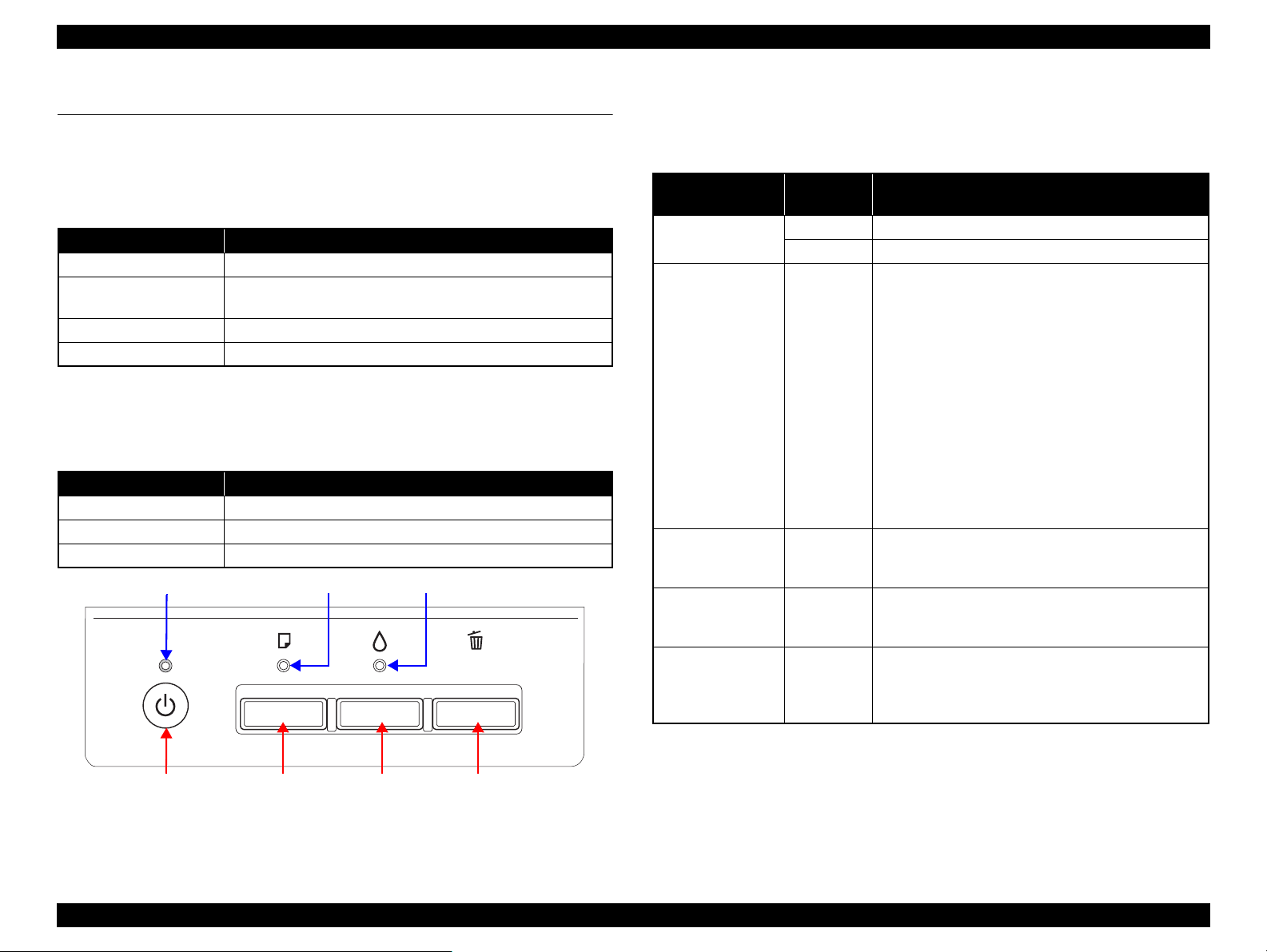
Power Button Ink ButtonPaper Button
Power LED Ink LEDPaper LED
Cancel Button
1.1 Operation Buttons & Indicators (LEDs)
1.1.1 Operation Buttons
The printer has the following four operation buttons.
Table 1-1. Operation Buttons
Button Function
Power Turn the power of this unit on/off.
Paper
Ink Start Initial Ink Charge or Head cleaning.
Cancel In motion:Cancels the job execution / Release error
1.1.2 Indicators (LEDs)
Three indicators (LEDs) are provided to indicate settings or printer status.
LED Function
Power LED (green) Indicates power on/off.
Paper LED (red) Indicates paper error.
Ink LED (red) Light when the maintenance error occurring.
In motion:Release error
In Idle: Load and Eject paper
Table 1-2. Indicators (LEDs)
1.1.3 Operation Buttons & LEDs Functions
Detailed information on the buttons and LEDs functions are listed below.
Table 1-3. Operation Button Functions
Button
Power
Paper On
Ink
(Press 3 seconds or
more)
Cancel On
Paper + Power On
Printer
Status
Off
On
On
Function
Turns the power on.
Turns the power off.
When the condition is Idle, Loads and Ejects the
paper.
When the following condition, loads the paper by
pressing this key. Release the error display and
continue the procedure if the paper loading is
success.
•Paper Out Error
• Multiple Feed Error
• Ink waste pad near end error
When the following condition, ejects the paper by
pressing this key. Release the error display and
continue the procedure if the paper ejecting is
success.
• Paper jam error
Runs a head cleaning.
Runs a Initial Ink Charge.
Stop printing, and cancel the job of print.
When the error occurs, it cancels error release &
stops printing and ejects the paper if it exists.
Print nozzle check pattern after normal Initializing
procedure is done.
If initial ink fill is not done, execute only initial ink
fill. Printer does not print nozzle check pattern.
Figure 1-1. Buttons & LEDs
Product Description Operation Buttons & Indicators (LEDs) 4
Confidential
Page 10
L1800 Revision A
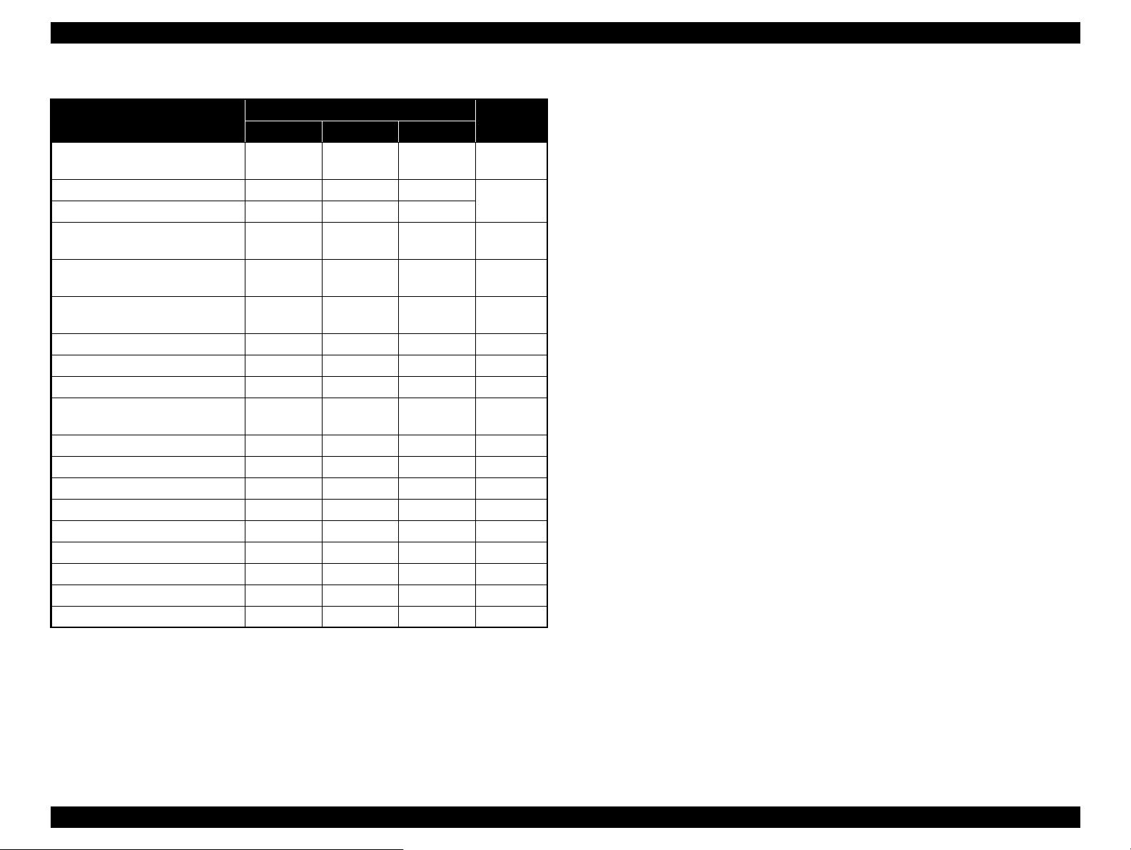
Table 1-4. Indicators (LEDs) Function
Printer Status
Power off (shutting down)
Firmware update (While preparing) -- -- --
Firmware update (Starting) Flashes OFF OFF
Fatal error OFF
Ink waste pad overflow error --
Ink waste pad near end error --
Paper jam error -- Flashes -- 6
Initial Ink Charge Preparing Flashes -- OFF 7
Initial Ink Charge Waiting ON -- ON 8
Initial Ink Charging
Multi-feed error -- ON -- 11
Paper out error -- ON -- 12
Ink Sequence Flashes -- -- 13
PC Printing Flashes -- -- 14
Stop printing & job canceling Flashes -- -- 15
Loading / Ejecting Flashes -- -- 16
Power On Sequence Flashes -- -- 17
Idle ON -- -- 18
Reset Requirement*
2
Power Paper Ink
Flashes at
high speed
Flashes
alternately 1
Indicators (LEDs)
-- -- 1
Flashes at
high speed
Flashes
alternately 1
Flashes
alternately 1
--
ON ON ON --
Flashes at
high speed
Flashes
alternately 2
Flashes
alternately 2
Flashes
alternately 2
Priority*
Note : --:No change
Flash: Repeats turning On and Off every 1.25 seconds.
1
2
3
4
5
9
Flash at high speed: Repeats turning On and Off every 0.5 seconds.
Flashes alternately 1:Same as the “Flash”
Flashes alternately 2:Repeats turning Off and On every 1.25 seconds.
Note *1: When two or more errors occur at the same time, the one with higher priority will be
indicated.
*2: The all LEDs light for 0.2 seconds when a reset requirement is received.
Product Description Operation Buttons & Indicators (LEDs) 5
Confidential
Page 11

L1800 Revision A
1.1.4 Errors & Remedies
Table 1-5. Errors & Remedies
Error Occurrence terms How to release
Fatal error When the unit detects an error which is impossible to work correctly. Turn off and restart the unit. (If occurs repeatedly, it must be repaired.)
Ink waste pad overflow error When the ink waste fluid comes full. Turn off the unit.
Change the absorber in the printer enclosure by a service person. and write
EEPROM’s data.
Ink waste pad near end error When the ink waste fluid nears full capacity. Press the Release error key.
By pressing the Stop key, it cancels print data.
Paper jam error When the paper loading or paper ejecting is not success.
Paper out error Failure to load paper to print.
Multiple feed error When the paper is ejected without printing.
When the fed paper size is longer than the specified value during
duplex printing.
Remove paper and push the Release error key to continue.
By pressing the Release error key, ejects the paper and continue the procedure if
the paper ejecting is success.
By pressing the Cancel key, it cancels error display and cancels print data and
returns from error status.
Set paper and push the Release error key to continue.
By pressing the Release error key, feeds the paper and continue the procedure if
the paper feeding is success.
By pressing the Stop key, it cancels error display and cancels print data and
returns from error status.
Reset the incorrectly ejected paper and push the Release error key to continue.
By pressing the Release error key, feeds the paper and continue the procedure if
the paper feeding is success.
By pressing the Stop key, it cancels error display and cancels print data and
returns from error status.
Note : For more information on the remedies, see “2.1.1 Troubleshooting according to Error Messages” (p.8).
Product Description Operation Buttons & Indicators (LEDs) 6
Confidential
Page 12

TROUBLESHOOTING
CHAPTER
2
Confidential
Page 13
L1800 Revision A
2.1 Overview
This chapter describes unit-level troubleshooting.
2.1.1 Troubleshooting according to Error Messages
After checking the printer LED and STM3 error indications, you can grasp the fault location using the check list in this section. When you find the fault location, refer to Chapter 3
“Disassembly and Reassembly” and change the corresponding part and/or unit. The following table indicates the check point reference tables corresponding to the error states (LED
and STM3).
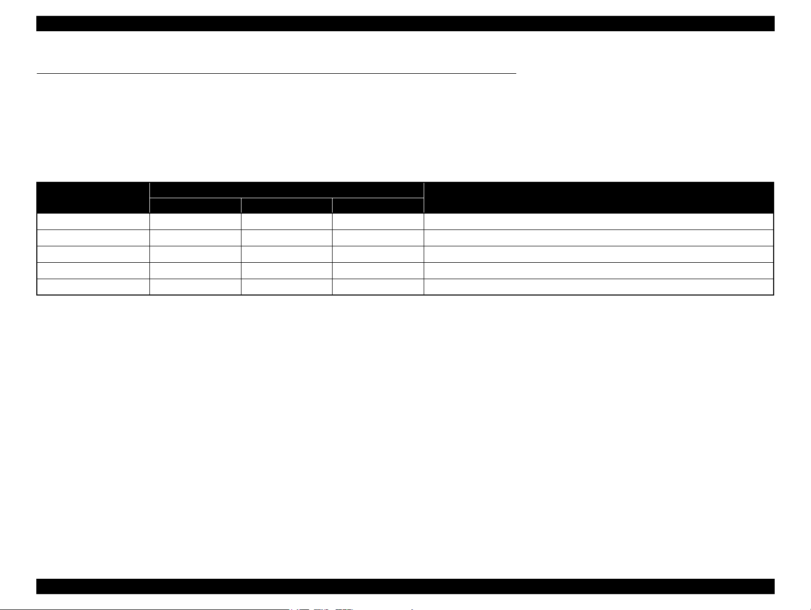
Table 2-1. List of Error Messages
Error Status
Paper out error
Paper jam error
Multi-feed error
Maintenance request
Fatal error
Note : --: No change
Flash: Repeats turning On and Off every 1.25 seconds.
Flash at high speed: Repeats turning On and Off every 0.5 seconds.
Flashes alternately 1: Same as the “Flash”
Flashes alternately 2: Repeats turning Off and On every 1.25 seconds.
Power Paper Ink
- Light -
-Flash-
- Light -
Off Flashes alternately 1 Flashes alternately 2
Off Flashes at high speed Flashes at high speed
LED Indications
See the table for Troubleshooting
Refer to Table 2-3 “Troubleshooting of Paper Out Error” (P.11)
Refer to Table 2-4 “Troubleshooting of Paper Jam Error” (P.13)
Refer to Table 2-5 “Troubleshooting of Multi-feed error” (P.14)
Refer to Table 2-6 “Troubleshooting of Maintenance Request” (P.14)
Refer to Table 2-7 “Troubleshooting of Fatal Error” (P.15)
Troubleshooting Overview 8
Confidential
Page 14
L1800 Revision A
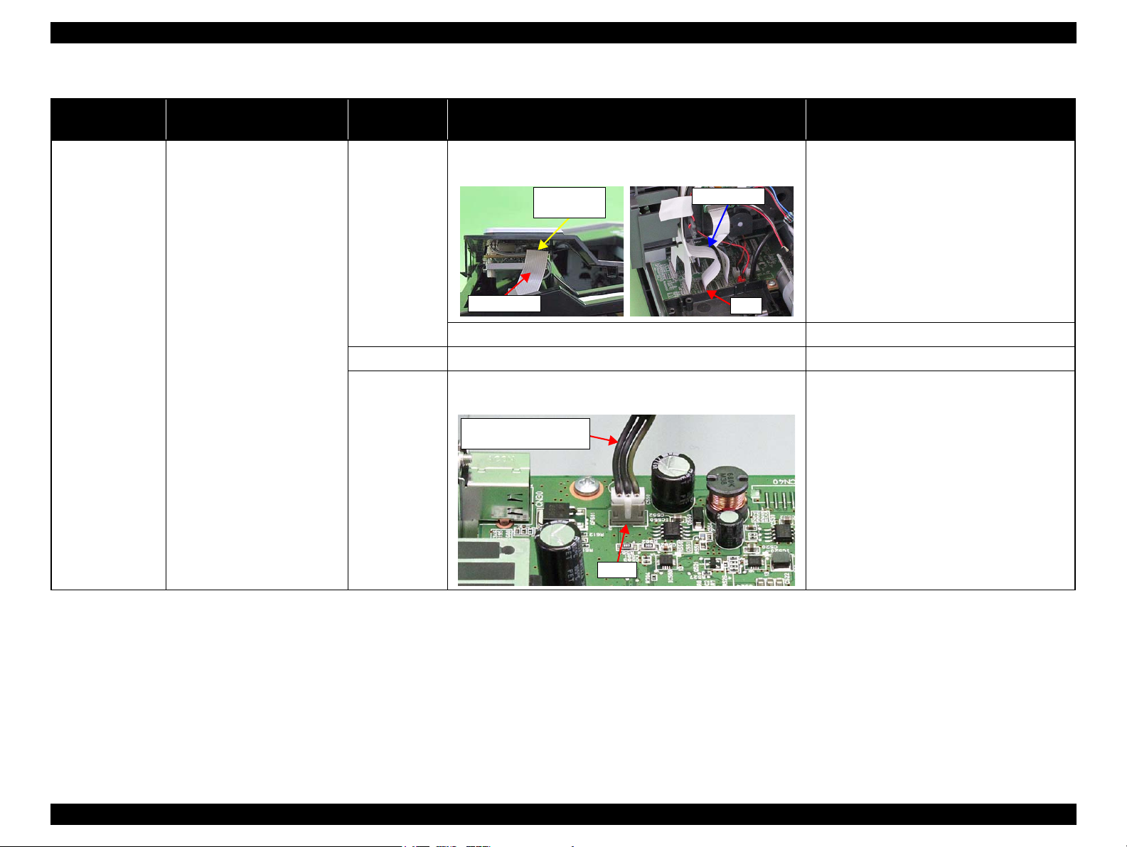
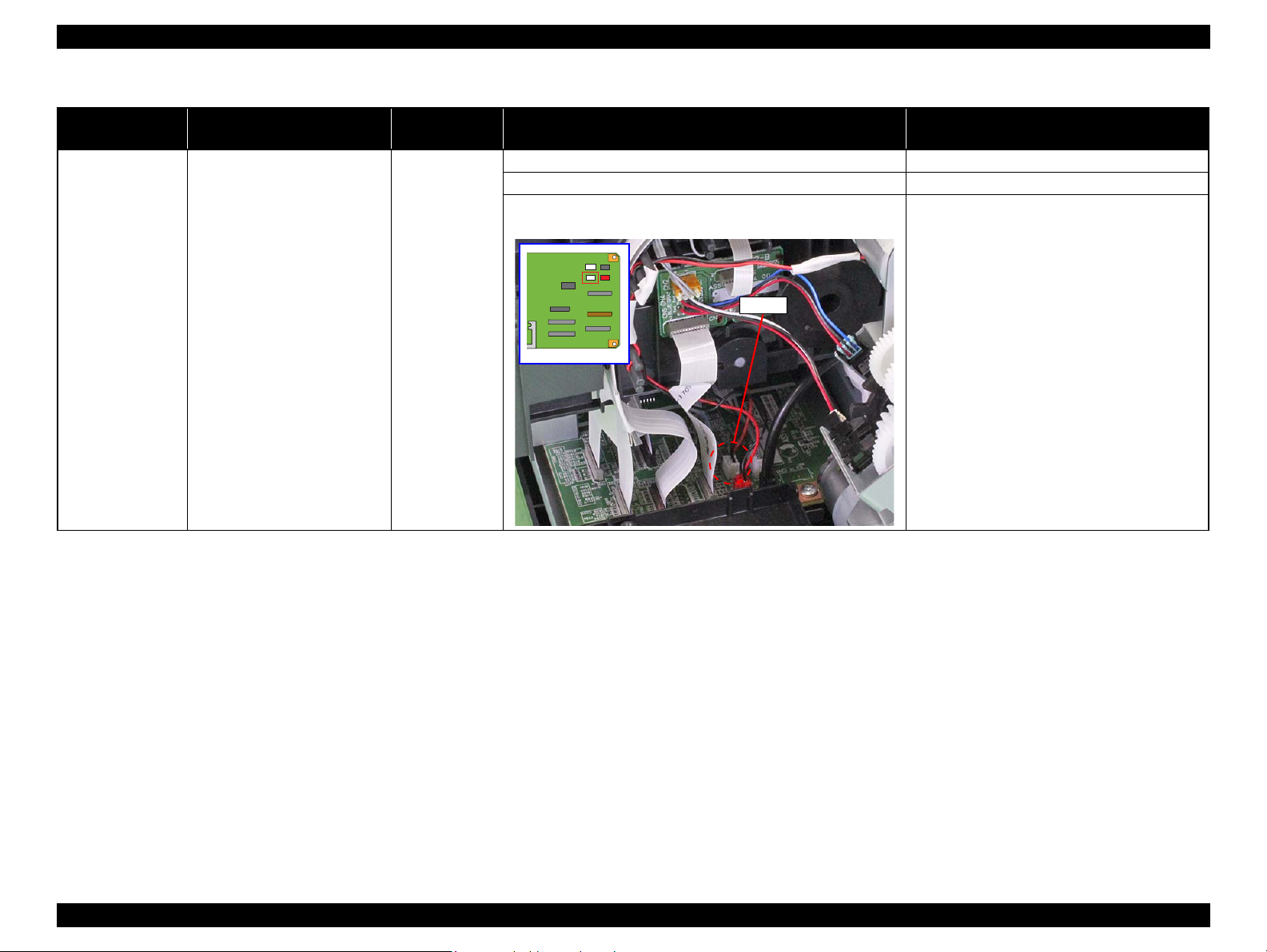
Panel FFC
CN4
Panel Board
connector
Panel FFC
Connector cable of the
Power Supply Board
CN60
Table 2-2. Troubleshooting of Communication Error
Occurrence
Timing
Phenomenon Detail
Faulty Part/
Part Name
Check Point Remedy
At power-on The printer does not operate at all. Panel FFC 1. Check that the Panel FFC is connected to the Panel Board
connector and Main Board connector CN4.
2. Check the Panel FFC for damages. 2. Replace the Panel FFC with a new one.
Panel Board 1. Check the Panel Board for damages. 1. Replace the Panel Board with a new one.
Power Supply
Board
1. Check that the connector cable of the Power Supply Board is
connected to the Main Board connector CN60.
1. Connect the Panel FFC to the Panel Board and
Main Board connectors.
1. Connect the connector cable of the Power
Supply Board to the Main Board connector
CN60.
Troubleshooting Overview 9
Confidential
Page 15

L1800 Revision A
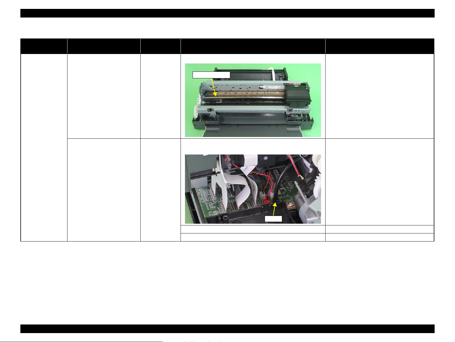
Fuse F1
Power Supply Board
Table 2-2. Troubleshooting of Communication Error
Occurrence
Timing
At power-on The printer does not operate at all. Power Supply
At operation Operation at power-on is normal,
Phenomenon Detail
but the error appears when the
print job is sent to the printer.
Faulty Part/
Part Name
Board
Interface cable 1. Check that the Interface cable is connected between the PC and
Check Point Remedy
2. Check that the Fuse F1 on the Power Supply Board has not
blown.
3. Check the components on the Power Supply Board for damage. 3. Replace the Power Supply Board with a new
printer.
2. Check the Interface cable for breaking. 2. Replace the Interface cable with a new one.
2. Replace the Power Supply Board with a new
one.
one.
1. Connect the Interface cable to the PC and
printer.
USB 1. Check that the PC and printer are connected via the USB hub. 1. Configure the USB ID setting.
Refer to Chapter 4 “Adjustment ”.
Printer Driver 1. Check that the printer driver for L1800 has already been
installed.
2. Check that the connected printer is L1800. 2. Connect the L1800 printer.
Main Board 1. Check that a wrong model name has not been input to the
EEPROM on the Main Board.
1. Install the printer driver for L1800.
1. Make the initial setting using the Adjustment
Program.
Refer to Chapter 4 “Adjustment ”.
Troubleshooting Overview 10
Confidential
Page 16
L1800 Revision A
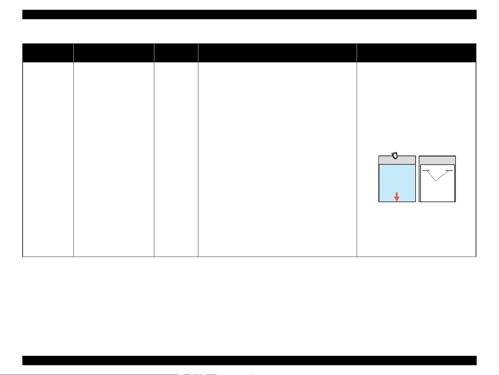
Cleaning sheet Postcard used
as mount
Non-adhesive part
Adhesive part
This side down
Stapling
Cloth damped
with alcohol
Table 2-3. Troubleshooting of Paper Out Error
Occurrence
Timing
Phenomenon Detail
At operation When the Paper Switch is
pressed, the LD Roller attempt to
feed paper but the paper is not
fed.
Faulty Part/
Part Name
Check Point Remedy
ASF Assy. 1. Check the LD Roller or Retard Roller of the ASF Assy for paper
dust and foreign matter.
1. Using a cleaning sheet, clean the LD Roller
and Retard Roller. The procedure is as follows.
(1) Place the cleaning sheet upside down and
put it into the ASF Assy.
(2) Press the Paper Switch to start paper feed.
(3) Repeat the above steps several times.
* To remove persistent contamination, staple
an alcohol-dampened cloth to a postcard
and clean the rollers in the following
method.
(1) Place the alcohol-dampened cloth toward
the LD Roller surface of the ASF Assy.
(2) Hold the mount top end securely and press
the Paper Switch.
(3) Repeat the paper feed sequence several
times to clean the LD Roller surface of the
ASF Assy.
Troubleshooting Overview 11
Confidential
Page 17
L1800 Revision A
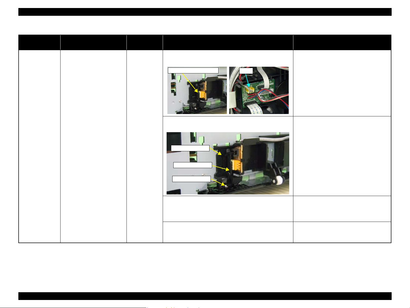
CN2
PE Sensor connector
Sensor Holder
Detection Lever
Torsion Spring
Table 2-3. Troubleshooting of Paper Out Error
Occurrence
Timing
At operation Paper Mismatch Error is
Phenomenon Detail
indicated.
Faulty Part/
Part Name
PE Sensor 1. Check that the connector cable of the PE Sensor is securely
connected to the PE Sensor and Relay Board connector CN2.
2. Check that the Sensor Holder is mounted to the Mechanical
frame correctly.
Check Point Remedy
1. Connect the connector cable of the PE Sensor
to the PE Sensor and connector CN2 on the
Relay Board correctly.
2. Install the Sensor Holder correctly.
3. Move the Detection Lever manually as when the paper passes,
and check that the Detection Lever returns to the original
position automatically by the Torsion Spring when released.
Refer to the above photo.
4. Using a tester, check that the PE Sensor is normal.
Paper absent : 2.4V or more
Paper present : 0.4V or less
Troubleshooting Overview 12
3. Replace the PE Sensor Holder Unit with a new
one.
4. Replace the PE Sensor Holder Unit with a new
one.
Confidential
Page 18
L1800 Revision A
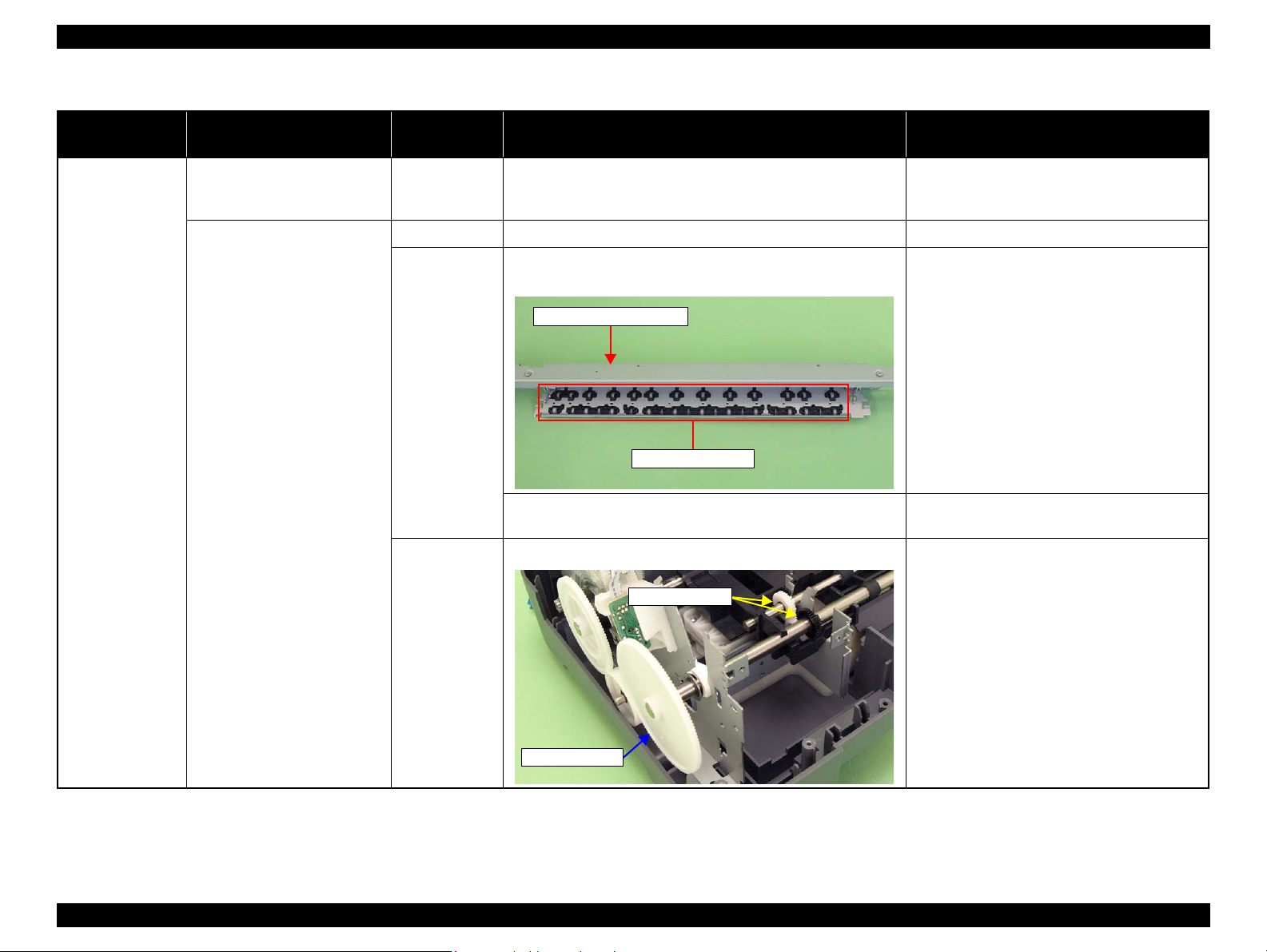
Paper EJ Frame Assy.
Star Wheel Units
Spur Gear 68
Spur Gear 16; B
Table 2-4. Troubleshooting of Paper Jam Error
Occurrence
Timing
At operation At the time of paper ejection, the
Phenomenon Detail
PF Roller advances the paper but
cannot eject it completely.
Paper is not ejected completely
and causes a jam near the Paper
Eject Frame.
Faulty Part/
Part Name
– 1. Check that the size of the fed paper is not larger than that of the
paper specified by the driver.
ASF Assy. 1. Check that the paper is fed along the Right Edge Guide. 1. Feed the paper along the Right Edge Guide.
Paper EJ Frame
Assy.
Spur Gear 68
Spur Gear 16; B
Paper EJ Roller
Assy.(front/rear)
1. Check that the Star Wheel Units have not come off the Paper EJ
Frame Assy.
2. Check the Paper EJ Frame Assy for deformation or damages. 2. Replace the Paper EJ Frame Assy with a new
1. Check the Spur Gear 68 or Spur Gear 16; B for damages. 1. Replace the Front (or Rear) Paper EJ Roller
Check Point Remedy
1. Tell the user that the paper size specified by the
driver is not available for the printer.
1. Securely install the Star Wheel Units to the
Paper EJ Frame Assy.
one.
Assy with a new one.
Troubleshooting Overview 13
Confidential
Page 19

L1800 Revision A
Extension Spring
Retard Roller
Assy
Bottom of
the ASF Assy
ASF Assy
Table 2-5. Troubleshooting of Multi-feed error
Occurrence
Timing
Any time During manual double-sided
Occurrence
Timing
At power-on At power-on, the printer does not
Phenomenon Detail
printing, multiple sheets are fed
at a time.
Phenomenon Detail
operate at all.
Faulty Part/Part
Name
ASF Assy 1. Check that the Retard Roller Assy is moving properly during the
feeding operation.
2. Check that the position of the ASF Guide Roller LDs has been
adjusted correctly.
Check Point Remedy
Table 2-6. Troubleshooting of Maintenance Request
Faulty Part/
Part Name
Waste Ink Pads 1. Using the Adjustment Program, check if the values of the
Protection Counter A and B have exceeded the threshold value.
Check Point Remedy
1. Attach the Extension Spring on the back side
of the Retard Roller Assy correctly.
Refer to Chapter 3 Retard Roller Assy (P.76).
2. Adjust the position of the ASF Guide Roller
LDs.
Refer to Chapter 3 ASF Assy (P.71).
1. Replace the Waste Ink Pads and reset the
Protection Counter A and B value with the
Adjustment Program.
Troubleshooting Overview 14
Confidential
Page 20
L1800 Revision A
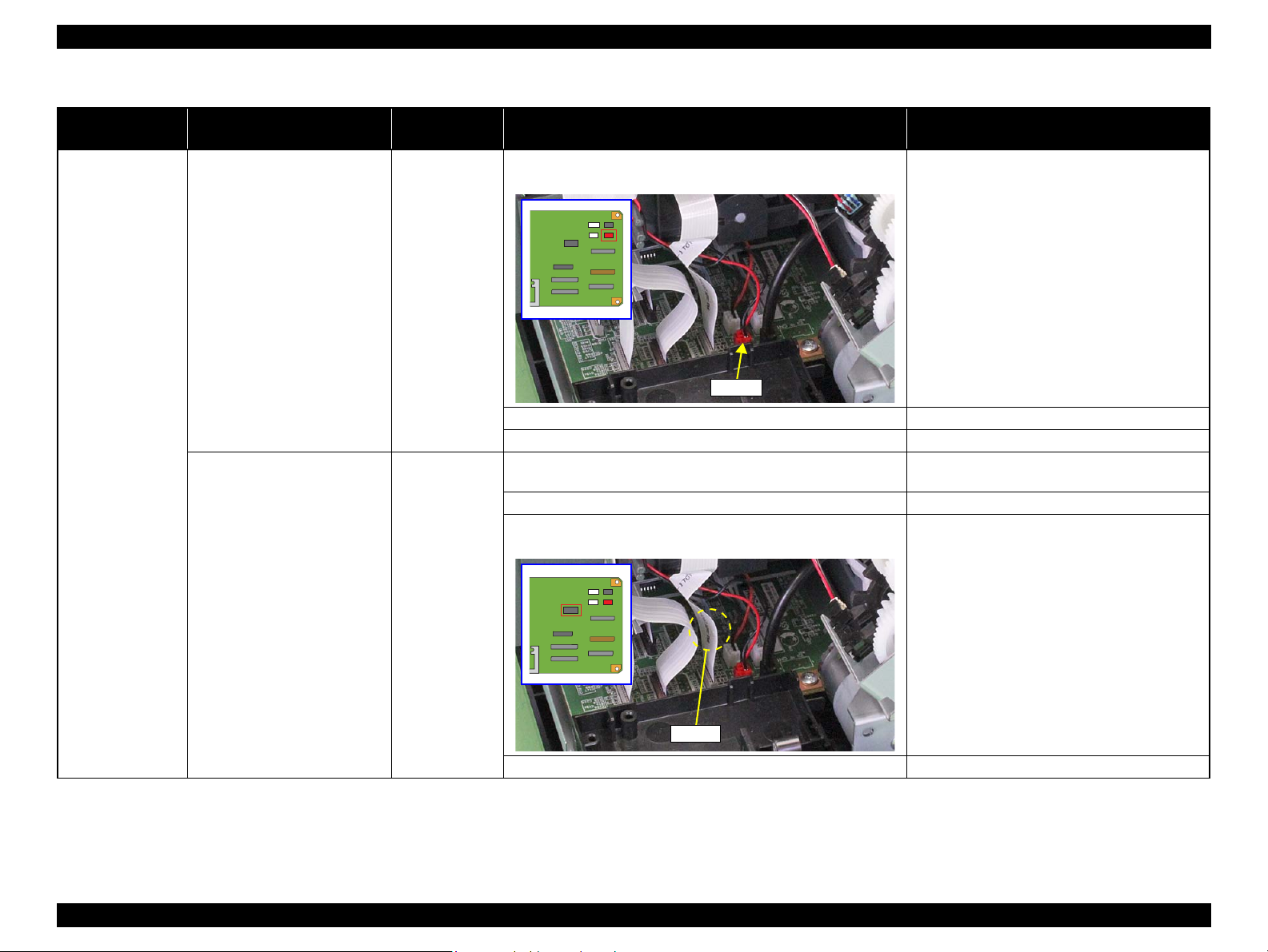
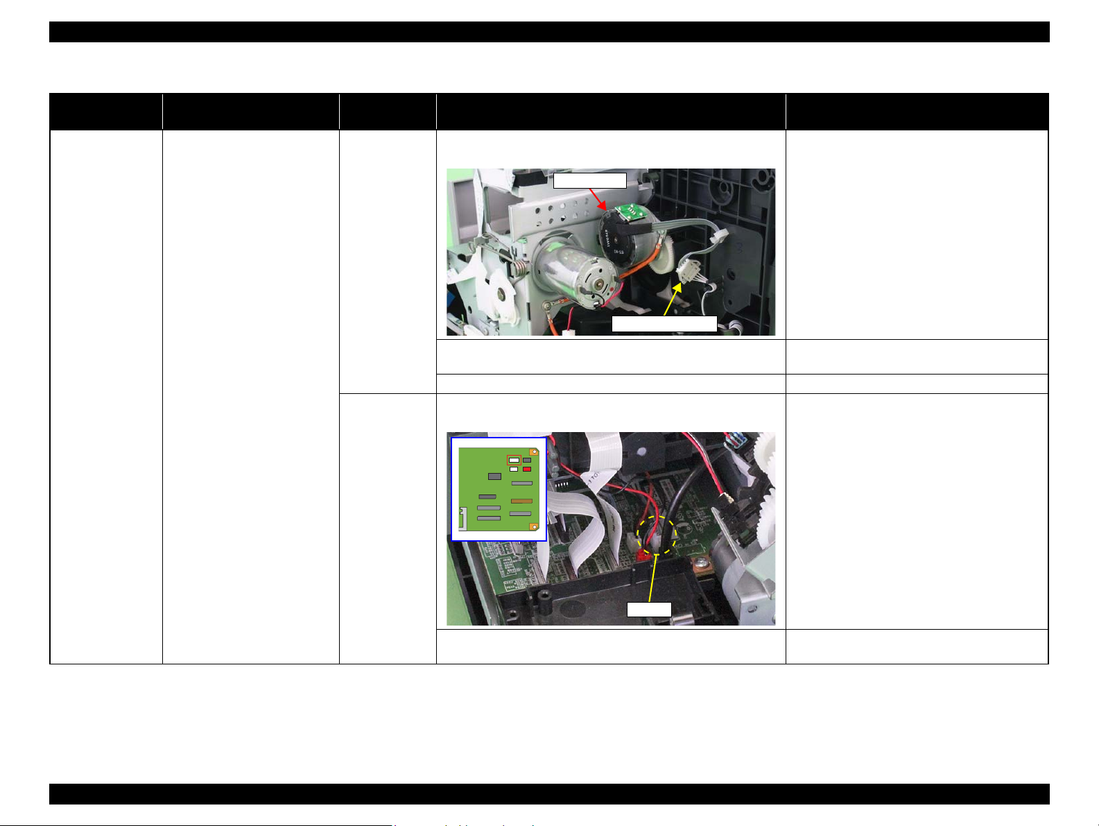
CN115
Table 2-7. Troubleshooting of Fatal Error
Occurrence
Timing
At power-on At power-on, the CR Motor does
Phenomenon Detail
not operate at all.
Faulty Part/
Part Name
CR Motor 1. Check the CR Motor connector cable for damages. 1. Replace the CR Motor with a new one.
2. Check if the CR Motor operates normally. 2. Replace the CR Motor with a new one.
3. Check that the CR Motor connector cable is connected to the
Main Board connector CN115.
Check Point Remedy
3. Connect the CR Motor connector cable to the
Main Board connector CN115.
Troubleshooting Overview 15
Confidential
Page 21
L1800 Revision A
Carriage Shaft
CN116
Table 2-7. Troubleshooting of Fatal Error
Occurrence
Timing
At power-on The power-on sequence is
Phenomenon Detail
executed but Fatal error is
displayed.
Faulty Part/
Part Name
CR drive
mechanism
Check Point Remedy
1. Check that the Carriage Shaft is lubricated with grease. 1. Wipe the surface of the Carriage Shaft with a
dry, soft cloth, and lubricate the Carriage
Shaft with grease G-71.
Refer to Chapter 5 “Maintenance ”.
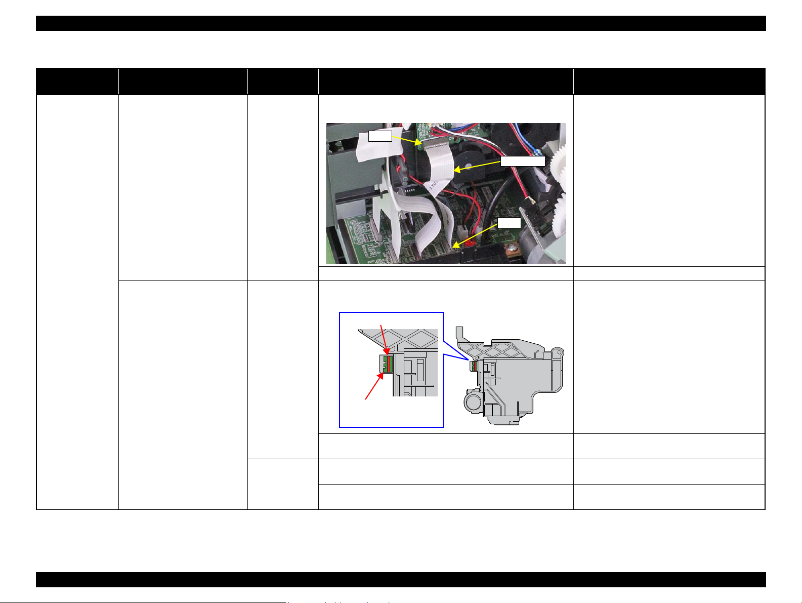
At power-on, the PF Motor does
not operate at all.
PF Motor 1. Check that the connector cable of the PF Motor is connected to
the Main Board connector CN116.
2. Check the PF Motor connector cable for damages. 2. Replace the PF Motor with a new one.
3. Check if the PF Motor operates normally. 3. Replace the PF Motor with a new one.
1. Connect the PF Motor connector cable to the
Main Board connector CN116.
Troubleshooting Overview 16
Confidential
Page 22
L1800 Revision A
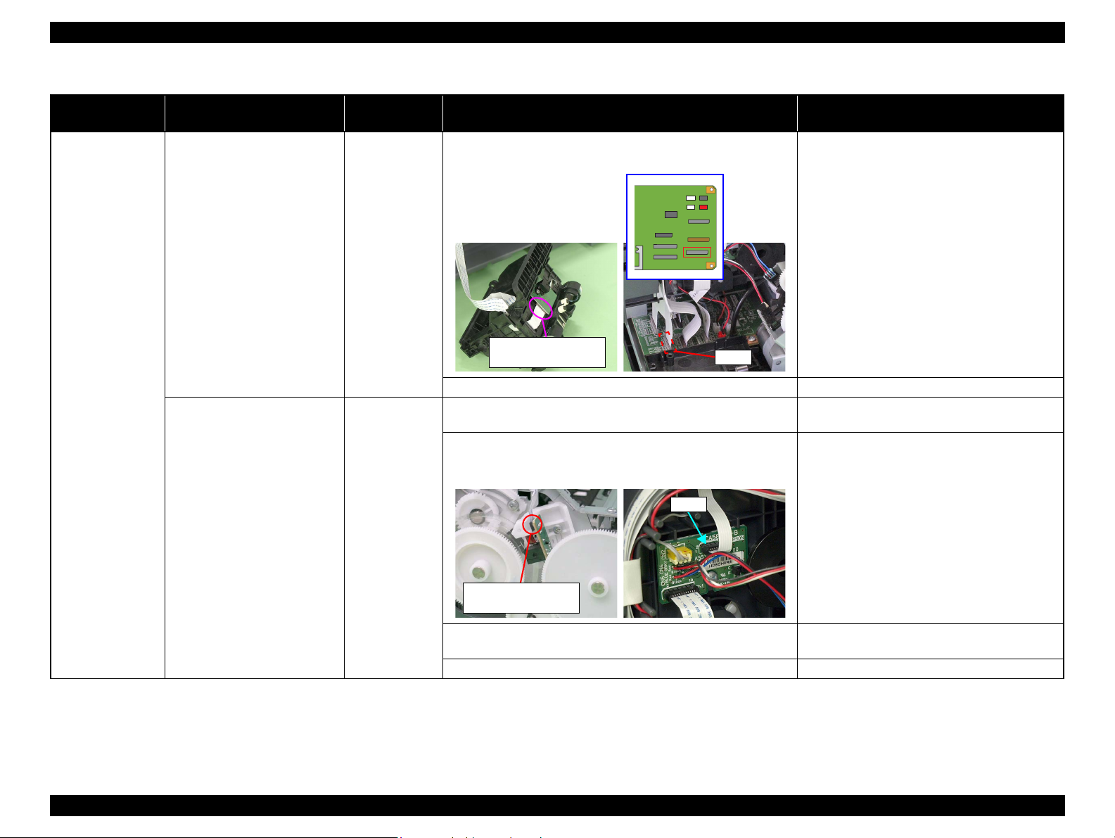
CN118
CN117
Table 2-7. Troubleshooting of Fatal Error
Occurrence
Timing
At power-on At power-on, the APG Motor
Phenomenon Detail
does not operate at all.
At power-on, the Pump Motor
does not operate at all.
Faulty Part/
Part Name
APG Motor 1. Check that the connector cable of the APG Motor is connected
to the Main Board connector CN118.
2. Check the APG Motor connector cable for damage. 2. Replace the APG Assy with a new one.
3. Check if the APG Motor operates normally. 3. Replace the APG Assy with a new one.
Pump Motor 1. Using a tester, check the resistance value of the Pump Motor.
Value of resistance: 10.3 ± 10%
2. Check the Pump Motor connector cable for damages. 2. Replace the Ink System with a new one.
3. Check that the Pump Motor connector cable is connected to the
Main Board connector CN117.
Check Point Remedy
1. Connect the APG Motor connector cable to
the Main Board connector CN118.
1. If the resistance value is abnormal, replace the
Ink System with a new one.
3. Connect the Pump Motor connector cable to
the Main Board connector CN117.
4. Check the Pump Motor connector cable for damages. 4. Replace the Ink System with a new one.
Troubleshooting Overview 17
Confidential
Page 23
L1800 Revision A
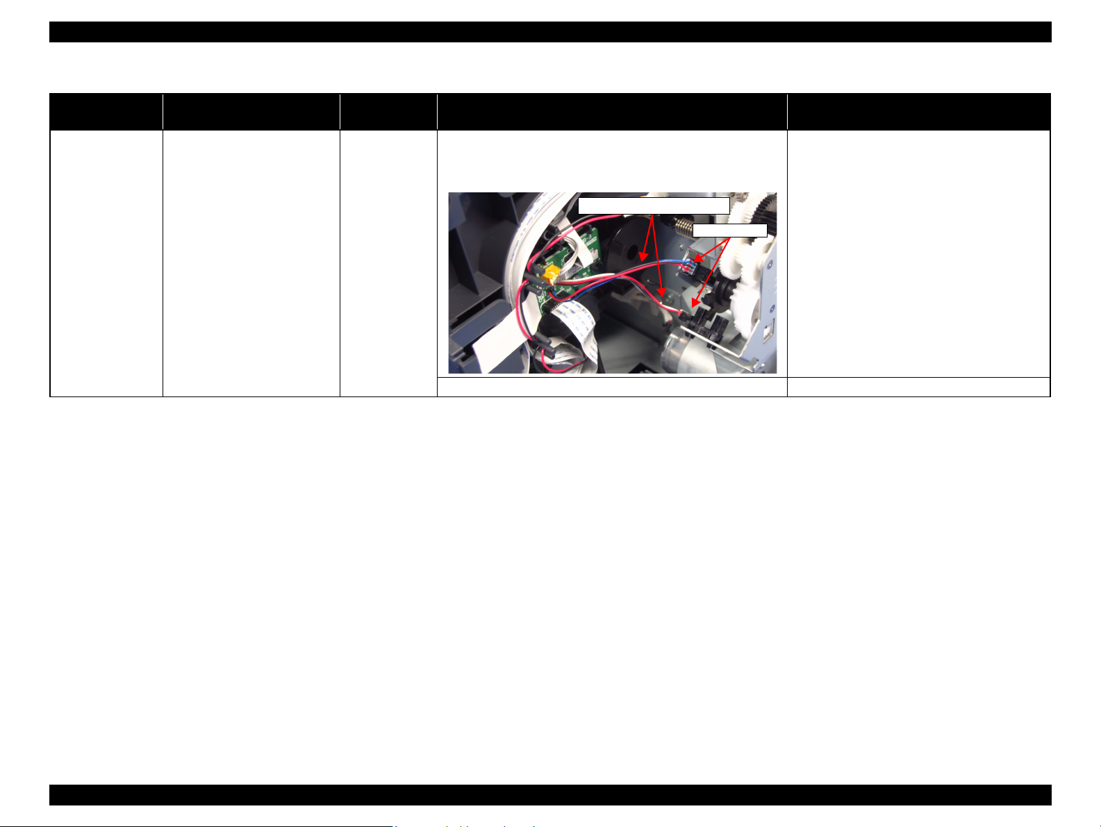
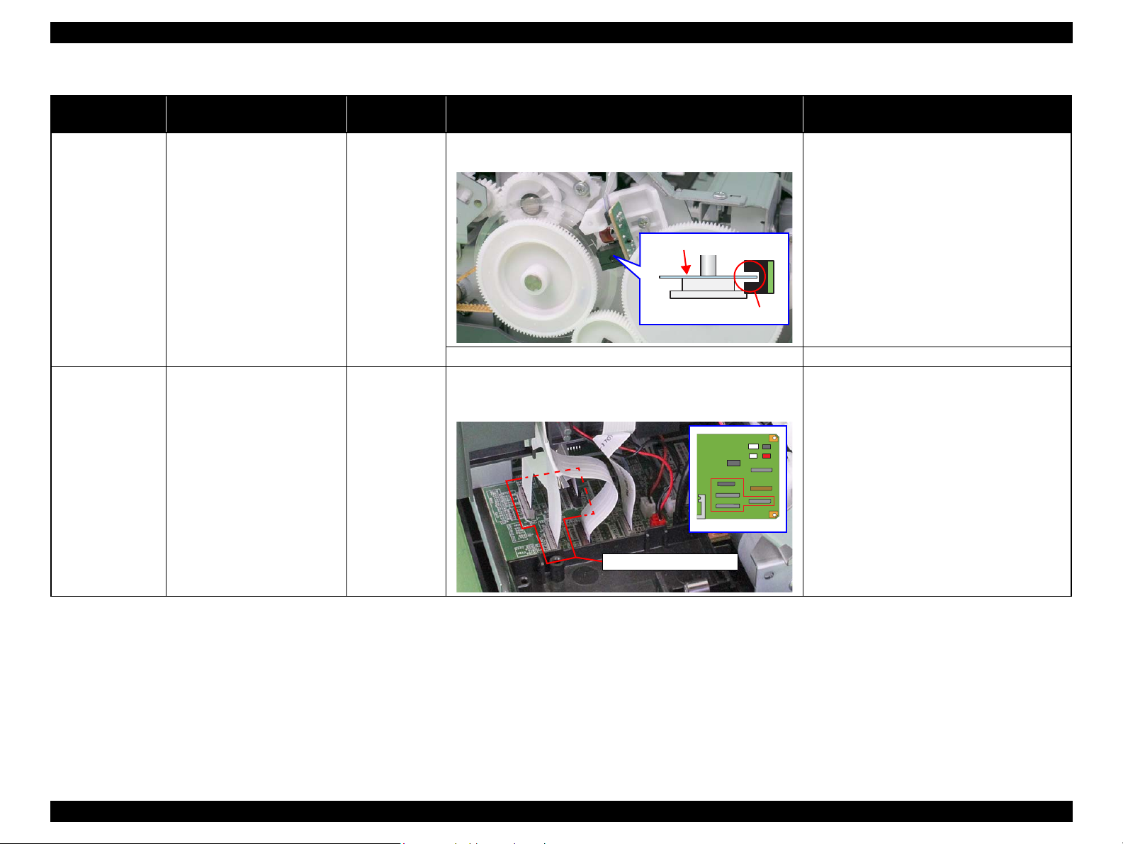
APG Sensors
APG Sensor connector cables
Table 2-7. Troubleshooting of Fatal Error
Occurrence
Timing
At power-on While the power-on sequence is
Phenomenon Detail
being executed, Fatal error is
displayed.
Faulty Part/
Part Name
APG Sensor 1. Check the APG Sensor connector cables is connected to the
APG Sensor connectors.
2. Check if the connector cables of the APG Sensor is broken.
3. Check the APG Sensors for damages. 3. Replace the APG Assy with a new one.
Check Point Remedy
1. Connect the APG Sensor connector cables to
the APG Sensor connectors.
2. Replace the ASF Assy with a new ones.
Troubleshooting Overview 18
Confidential
Page 24
L1800 Revision A
Relay connector
ASF Motor
CN119
Table 2-7. Troubleshooting of Fatal Error
Occurrence
Timing
At power-on While the power-on sequence is
Phenomenon Detail
being executed, Fatal error is
displayed.
Faulty Part/
Part Name
ASF Motor 1. Check that the connector cable of the ASF Motor is connected
to the Relay connector.
Check Point Remedy
1. Connect the connector cable of the ASF
Motor to the Relay connector.
Relay connector
cable
2. Using a tester, check the resistance value of the ASF Motor.
Value of resistance: 7.0 ±10%
3. Check the ASF Motor connector cable for damages. 3. Replace the ASF Motor with a new one.
1. Check that the Relay connector cable is connected to the Main
Board connector CN119.
2. Check the Relay connector cable for damages. 2. Replace the Relay connector cable with a new
2. If the resistance value is abnormal, replace the
ASF Motor with a new one.
1. Connect the Relay connector cable to the
Main Board connector CN119.
one.
Troubleshooting Overview 19
Confidential
Page 25
L1800 Revision A
CN1
CN5
Relay FFC
CR Scale
CR Encoder
Sensor Board
Table 2-7. Troubleshooting of Fatal Error
Occurrence
Timing
At power-on While the power-on sequence is
Phenomenon Detail
being executed, Fatal error is
displayed.
At power-on, the Carriage Unit
moves away from the home
position and bumps against the
right of the Frame, then hits the
left of the Frame.
Faulty Part/
Part Name
Relay FFC 1. Check that the Relay FFC is connected to the Relay Board
connector CN1 and Main Board connector CN5.
2. Check the Relay FFC for damages. 2. Replace the Relay FFC cable with a new one.
CR Scale 1. Check that the CR Scale is inserted in the slit of the CR
Encoder Sensor.
Check Point Remedy
1. Connect the Relay FFC to the Relay Board
connector CN1 and Main Board connector
CN5.
1. Insert the CR Scale into the slit of the CR
Encoder Sensor.
2. Check the CR Scale for damages and dirt. 2. Wipe off the dirt completely or replace the CR
Scale with a new one.
CR Encoder
Troubleshooting Overview 20
Sensor Board
1. Check the CR Encoder Sensor for paper dust, etc. 1. Remove the paper dust, etc. from the CR
Encoder Sensor.
2. Check the CR Encoder Sensor Board for damages. 2. Replace the CR Encoder Sensor Board with a
new one.
Confidential
Page 26
L1800 Revision A
CN9
CR Encoder Sensor
Board connector
CN6
PF Encoder Sensor
Board connector
Table 2-7. Troubleshooting of Fatal Error
Occurrence
Timing
At power-on At power-on, the Carriage Unit
Phenomenon Detail
moves away from the home
position and bumps against the
right of the Frame, then hits the
left of the Frame.
At power-on, the PF Roller
rotates fast about a half turn.
Faulty Part/
Part Name
Sensor FFC 1. Check that the Sensor FFC is connected to the CR Encoder
Sensor Board connector and Main Board connector CN9.
2. Check the Sensor FFC for damages. 2. Replace the Sensor FFC with a new one.
PF Encoder
Sensor Holder
1. Check that the PF Encoder Sensor Holder is mounted correctly. 1. Install the PF Encoder Sensor Holder
2. Check that the FFC of the PF Encoder Sensor is securely
connected to the PF Encoder Sensor Board connector and Relay
Board connector CN6.
Check Point Remedy
1. Connect the Sensor FFC to the CR Encoder
Sensor Board connector and Main Board
connector CN9.
correctly.
2. Connect the PF Encoder Sensor FFC to the PF
Encoder Sensor Board and Relay Board
connector CN6.
3. Check the PF Encoder Sensor for paper dust, etc. 3. Remove the paper dust, etc. from the PF
Encoder Sensor.
4. Check if the PF Encoder or the FFC is damaged. 4. Replace the PF Encoder with a new one.
Troubleshooting Overview 21
Confidential
Page 27
L1800 Revision A
Slit
PF Scale
CN9, CN12, CN13, CN14
Table 2-7. Troubleshooting of Fatal Error
Occurrence
Timing
At power-on At power-on, the PF Roller
During printing After receiving a print data, an
Phenomenon Detail
rotates fast about a half turn.
error is displayed on the LED
and STM3.
Faulty Part/
Part Name
PF Scale 1. Check that the PF Scale is inserted in the slit of the PF Encoder
Sensor.
2. Check the PF Scale for damages and dirt. 2. Replace the PF Scale with a new one.
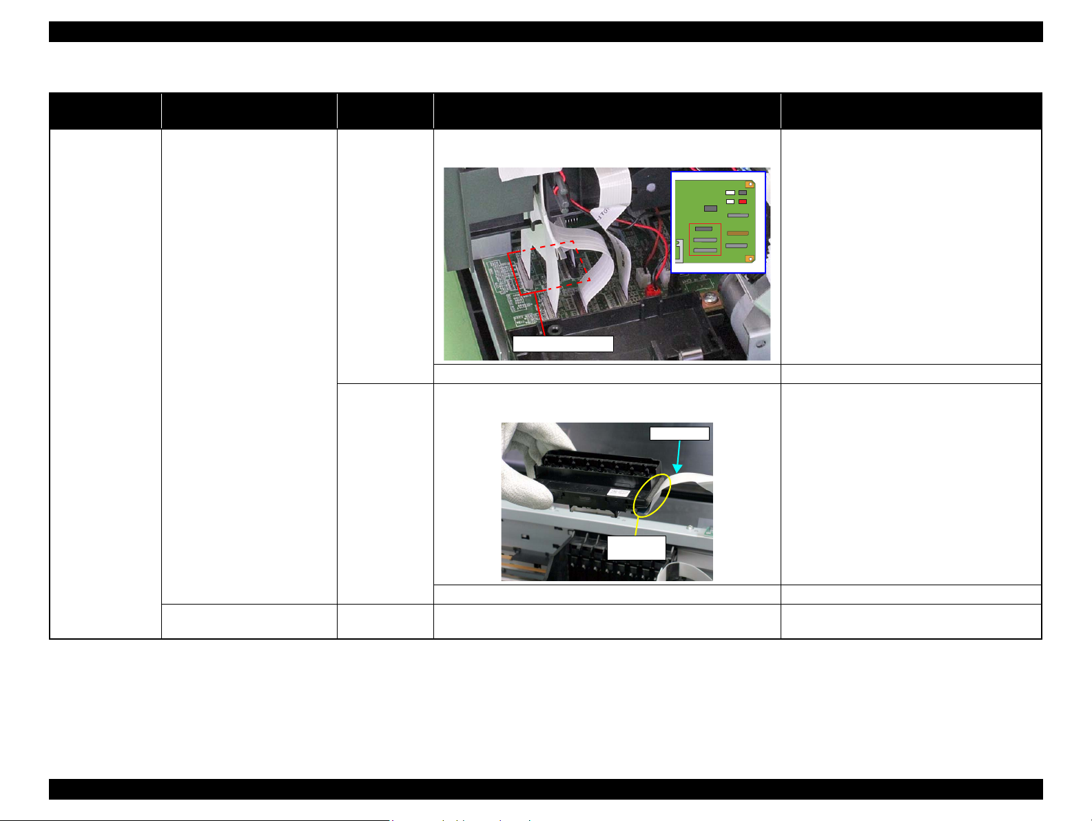
Head FFC
Sensor FFC
1. Check that the Head FFC and the Sensor FFC are securely
connected to the Main Board connectors CN9, CN12, CN13,
and CN14.
Check Point Remedy
1. Install the PF Scale in the slit of the PF
Encoder Sensor correctly.
1. Connect the Head FFC and the Sensor FFC to
the Main Board connectors CN9, CN12,
CN13, and CN14.
Troubleshooting Overview 22
Confidential
Page 28
L1800 Revision A
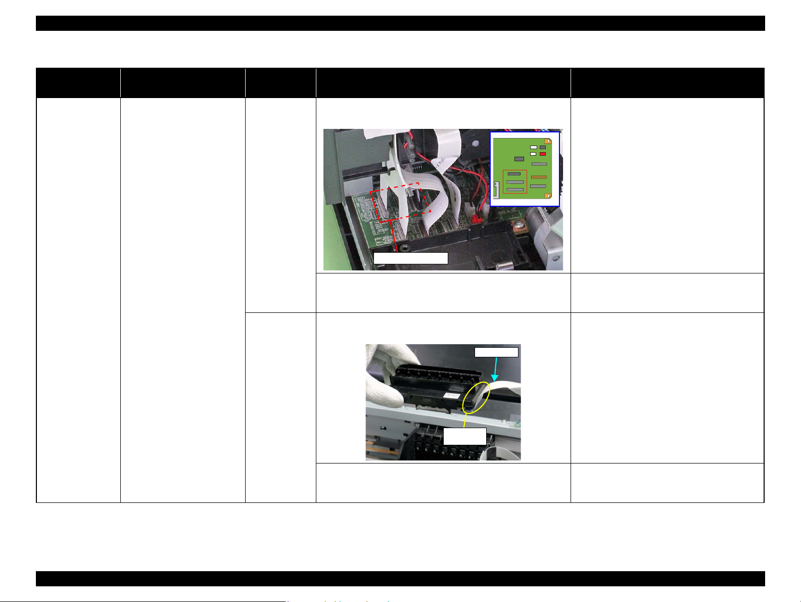
CN12, CN13, CN14
Print Head
Connector
Head FFC
Table 2-7. Troubleshooting of Fatal Error
Occurrence
Timing
During printing After starting to print, ink is not
Phenomenon Detail
ejected and paper stops midway.
Faulty Part/
Part Name
Head FFC 1. Check that the Head FFC is securely connected to the Main
Board connectors CN12, CN13, and CN14.
2. Check the Head FFC for damages. 2. Replace the Head FFC with a new one.
Head FFC 1. Check that the Head FFC is securely connected to the Print
Head connectors.
Check Point Remedy
1. Connect the Head FFC to the Main Board
connectors CN12, CN13, and CN14.
1. Connect the Head FFC to the CR Relay Board
connectors CN1 and CN2.
2. Connect the Head FFC to the Print Head
connectors.
2. Check the Head FFC for damages. 3. Replace the Head FFC with a new one.
Ink is not ejected from most
nozzles.
Troubleshooting Overview 23
Print Head 1. Check for occurrence of Head Hot. 1. Replace the Print Head with a new one.
Confidential
Page 29
L1800 Revision A
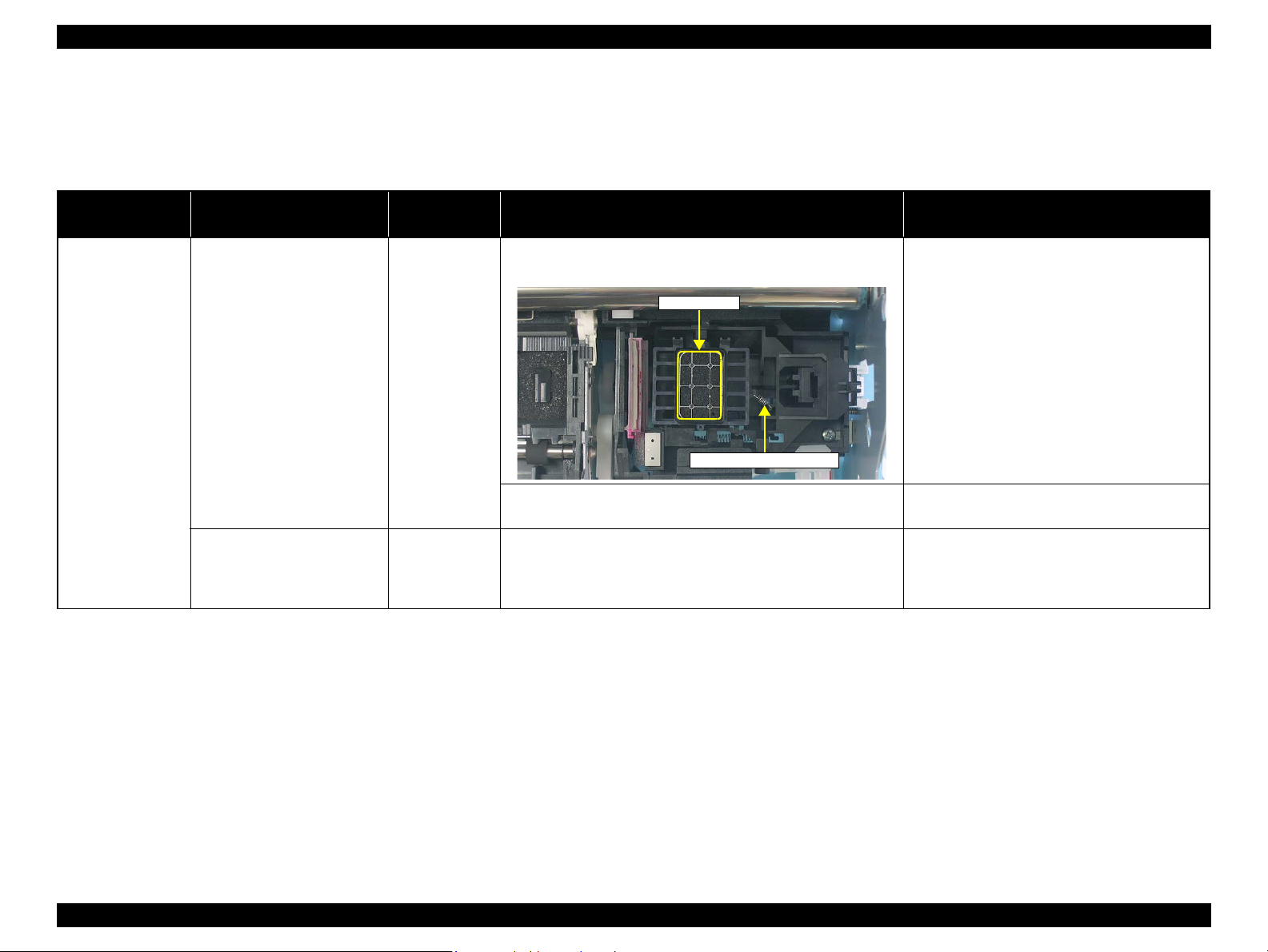
Seal Rubbers
Extension Spring, 1.19 IS
2.1.2 Troubleshooting based on Observed Faults
This section provides troubleshooting procedures based on observed faults such as print quality troubles and abnormal noise.
Table 2-8. Print Quality Troubles
Observed Faults Details of the Fault
Dot missing and
mixed colors
Inks are not ejected from the
Print Head to the Cap.
Although inks are ejected from
the Print Head to the Cap, the
trouble still occurs after
executing a cleaning cycle.
Faulty Part/
Part Name
Ink System Unit
(Cap)
Print Head 1. Run a Nozzle Check, and check the printed pattern if it has
1. Check for foreign matter around the Seal Rubber on the Cap
Unit.
2. Check that the Extension Spring 1.19 IS is correctly installed to
the Cap Unit.
broken lines or missing segments.
Check Point Remedy
1. Remove the foreign matter around the Seal
Rubber completely.
2. Replace the Ink System Unit with a new one.
1. After running a Head Cleaning, check the
Nozzle Check Pattern again.
Troubleshooting Overview 24
Confidential
Page 30
L1800 Revision A
CN12, CN13, CN14
Print Head
Connector
Head FFC
Table 2-8. Print Quality Troubles
Observed Faults Details of the Fault
Dot missing and
mixed colors
Although inks are ejected from
the Print Head to the Cap, the
trouble still occurs after
executing a cleaning cycle.
Faulty Part/
Part Name
Head FFC 1. Check that the Head FFC is securely connected to the Main
Board connectors CN12, CN13, and CN14.
2. Check the Head FFC for damages. 2. Replace the Head FFC with a new one. If the
Head FFC 1. Check that the Head FFC is securely connected to the Print Head
connectors.
Check Point Remedy
1. Connect the Head FFC to the Main Board
connectors CN12, CN13, and CN14.
trouble still occurs after replacing it, replace the
Print Head with a new one.
1. Connect the Head FFC to the CR Relay Board
connectors CN1 and CN2.
2. Connect the Head FFC to the Print Head
connectors.
2. Check the Head FFC for damages. 3. Replace the Head FFC with a new one. If the
trouble still occurs after replacing it, replace the
Troubleshooting Overview 25
Print Head with a new one.
Confidential
Page 31

L1800 Revision A
Cleaner Blade
CN12, CN13, CN14
Table 2-8. Print Quality Troubles
Observed Faults Details of the Fault
Dot missing and
mixed colors
Horizontal or vertical
banding / Getting
smeared
Although inks are ejected from
the Print Head to the Cap, the
trouble still occurs after
executing a cleaning cycle.
Although inks are ejected from
the Print Head to the Cap, the
trouble still occurs after
executing a cleaning cycle.
Faulty Part/
Part Name
Ink System Unit
Cleaner Blade
Main Board 1. Check the Main Board for damages. 1. Replace the Main Board with a new one.
Head FFC 1. Check that the Head FFC is securely connected to the Main
1. Check if the Cleaner Blade is covered with paper dust or is bent. 1. Replace the Ink System Unit with a new one.
Board connectors CN12, CN13, and CN14.
Check Point Remedy
1. Connect the Head FFC to the Main Board
connectors CN12, CN13, and CN14.
2. Check the Head FFC for damages. 2. Replace the Head FFC with a new one. If the
trouble still occurs after replacing it, replace the
Print Head with a new one.
Troubleshooting Overview 26
Confidential
Page 32

L1800 Revision A
Print Head
Connector
Head FFC
Table 2-8. Print Quality Troubles
Observed Faults Details of the Fault
Horizontal or vertical
banding / Getting
smeared
Although inks are ejected from
the Print Head to the Cap, the
trouble still occurs after
executing a cleaning cycle.
Faulty Part/
Part Name
Head FFC 1. Check that the Head FFC is securely connected to the Print Head
connectors.
2. Check the Head FFC for damages. 3. Replace the Head FFC with a new one. If the
Print Head 1. Check if the print quality recovers after running a cleaning. 1. Run the cleaning several times. If the trouble
Main Board 1. Check the Main Board for damages. 1. Replace the Main Board with a new one.
Check Point Remedy
1. Connect the Head FFC to the CR Relay Board
connectors CN1 and CN2.
2. Connect the Head FFC to the Print Head
connectors.
trouble still occurs after replacing it, replace the
Print Head with a new one.
still occurs, replace the Print Head with a new
one.
Troubleshooting Overview 27
Confidential
Page 33

L1800 Revision A
Direction of CR
movement
Direction of CR
movement
Table 2-8. Print Quality Troubles
Observed Faults Details of the Fault
Vertical or horizontal
banding / Color
shading
The printout has banding vertical
to the CR moving direction and
is not evenly colored.
* If the trouble still occurs after
doing all measures described
in the right-hand columns,
replace the CR Motor with a
new one.
Narrow stripes of the same width
appear horizontally to the CR
moving direction.
Faulty Part/
Part Name
Adjustment 1. For printing in the Bi-D mode, check that the Bi-D Adjustment
has been performed properly.
Print Head 1. Run a Nozzle Check, and check the printed pattern if it has
broken lines or missing segments.
Carriage Shaft 1. Check the surfaces of the Carriage Shaft for foreign matter. 1. Remove foreign matter from the Carriage Shaft.
2. Check that the Carriage Shaft is fully lubricated with grease. 2. Wipe the grease applied to the Carriage Shaft
3. Check that the Carriage Shaft is mounted horizontally. 3. Reassemble the Carriage Shaft correctly.
4. Check the Carriage Shaft for damages. 4. Replace the Carriage Shaft with a new one.
Printer Driver and
the Paper
Print Head 1. Run a Nozzle Check, and check the printed pattern if it has
PF Roller Shaft 1. Check the surface of the PF Roller Shaft for foreign matter. 1. Clean the PF Roller surface carefully.
1. Check if appropriate paper is used in accordance with the Printer
Driver settings.
broken lines or missing segments.
2. Check the PF Roller Shaft for damages. 2. Replace the PF Roller with a new one.
Check Point Remedy
1. Perform Bi-D Adjustment to eliminate
displacements between the upper and lower
lines.
Refer to Chapter 4 “Adjustment ”.
1. Perform the Head Cleaning, then check the
Nozzle Check Pattern.
Refer to Chapter 4
If the trouble still occurs, replace the Print Head
with a new one.
with a dry, soft cloth, and then apply G-71
grease.
Refer to Chapter 5 “Maintenance ”.
1. Use the appropriate type of paper in accordance
with the Printer Driver.
1. Perform the Head Cleaning, then check the
Nozzle Check Pattern.
Refer to Chapter 4
If the trouble still occurs, replace the Print Head
with a new one.
“Adjustment”
“Adjustment”
.
.
* If the trouble still occurs after
doing all measures described
in the right-hand columns,
replace the PF Motor with a
new one.
Troubleshooting Overview 28
Confidential
Page 34

L1800 Revision A
Paper EJ Frame Assy.
Star Wheel Units
Table 2-8. Print Quality Troubles
Observed Faults Details of the Fault
Vertical or horizontal
banding / Color
shading
Paper EJ Roller
traces appear on the
printout.
When printing at 360 dpi,
horizontal banding and color
unevenness appears at a constant
frequency.
Star Wheel Rollers traces appear
in the CR moving direction.
Printout is faint or blurry.
The bottom of the printout is not
evenly colored.
Traces of the Paper EJ Roller
appear on the printed paper.
Faulty Part/
Part Name
Adjustment 1. Check that PF Adjustment has executed properly. 1. Perform PF Adjustment properly.
2. Check for Dot missing. 2. Replace the Ink System Unit with a new one.
Paper EJ Frame
Assy.
Printer Driver and
the Paper
Print Head 1. Using the Adjustment Program, check that the correct Head ID has
Adjustment 1. Check if the Positioning Adjustment of PF Roller Shaft Retainer
Printer Driver and
the Paper
Front and Rear
Paper EJ Roller
Assys.
1. Check that the Star Wheel Units have not come off or the Star
Wheel Rollers turns normally.
1. Check that adequate paper is used according to the setting of the
Printer Driver.
been written to the EEPROM.
has been performed properly.
1. Check if appropriate paper is used in accordance with the Printer
Driver settings.
1. Check if the Paper EJ Roller is clean or not. 1. Clean the Paper EJ Roller with a soft cloth.
Check Point Remedy
Refer to Chapter 4 “Adjustment ”.
1. Install the Star Wheel Units to the Paper EJ
Frame Assy correctly.
1. Use the appropriate type of paper in accordance
with the Printer Driver.
1. Using the Adjustment Program, enter the 24digits code of the Head ID to the EEPROM.
Refer to Chapter 4 “Adjustment ”.
1. Make adjustments according to the specified
adjustment priority.
Refer to Chapter 4 “Adjustment ”.
1. Use the appropriate type of paper in accordance
with the Printer Driver.
Troubleshooting Overview 29
Confidential
Page 35

L1800 Revision A
Front Paper Guide Pad Front Paper Guide
Table 2-8. Print Quality Troubles
Observed Faults Details of the Fault
The printout is
stained with ink.
The non-printed side or the
bottom of the printout is dirty
with ink.
When the paper size in the sent
print data is larger than the size
of the fed paper, data are printed
on the Front Paper Guide,
extending off the paper.
Ink smudges appear on the blank
area of the printout.
Faulty Part/
Part Name
Front Paper
Guide Pad
PW sensor 1. Check that the PW Sensor FFC is connected. 1. Connect the PW Sensor FFC.
Paper EJ Frame
Assy.
Front Paper
Guide
Front Paper
Guide Pad
1. Check that heaps of ink are not formed on the Front Paper Guide
Pad and that the Front Paper Guide Pad is installed securely and
evenly in the setting position.
2. Check that the PW Sensor is not faulty. 2. Replace the PW Sensor with a new one.
1. Check the Star Wheel Rollers for ink stain. 1. Clean the Star Wheel Rollers with a soft cloth.
1. Check the Front Paper Guide for ink stain. 1. Clean the Front Paper Guide with a soft cloth.
1. Check if ink heaps are formed on the Front Paper Guide Pad. 1. Replace the Front Paper Guide with a new one.
Check Point Remedy
1. If heaps of ink are formed, replace the Front
Paper Guide. If it has been confirmed that the
Ink pads have risen, reinstall the Front Paper
Guide Pad correctly.
Troubleshooting Overview 30
Confidential
Page 36

L1800 Revision A
Driven Roller Shaft
Rear Paper EJ Roller AssyFront Paper EJ Roller Assy
Cleaner Blade
Table 2-8. Print Quality Troubles
Observed Faults Details of the Fault
The printout is
stained with ink.
Ink smudges appear on the blank
area of the printout.
Faulty Part/
Part Name
Front and Rear
Paper EJ Roller
Assys
Driven Roller
Shaft
Ink System Unit 1. Check that wiping operation was performed properly. 1. Install the Cleaner blade correctly or replace it
1. Check the Front and Rear Paper EJ Roller Assys for ink stain. 1. Clean the Front and Rear Paper EJ Roller Assys
1. Check the Driven Roller Shaft for ink stain. 1. Clean the Driven Roller Shaft with a soft cloth.
Check Point Remedy
with a soft cloth.
with a new one.
Troubleshooting Overview 31
Confidential
Page 37

L1800 Revision A
PF Roller Shaft
Table 2-8. Print Quality Troubles
Observed Faults Details of the Fault
The printout is
stained with ink.
The printout is
grainy.
Ink smudges appear on the blank
area of the printout.
Images are printed grainy in all
print modes. Or the image looks
rough.
When printed at 5760 dpi, the
printed images are poor or
grainy.
Faulty Part/
Part Name
PF Roller Shaft 1. Check the PF Roller Shaft for ink stain. 1. Clean the PF Roller Shaft with a soft cloth.
Adjustment
Main Board
Print Head
Adjustment
Main Board
Print Head
1. Check that PG, Bi-D and Head Angular Adjustments have been
made properly.
2. Print the adjustment check patterns and check if they are grainy. 2. If the images look still grainy after adjustment,
1. After making sure that PG, Bi-D and Head Angular Adjustments
have been made correctly, check whether PW Sensor has been
adjusted properly.
2. Print the adjustment check patterns and check if the printed
images are still poor or grainy.
Check Point Remedy
1. Make the adjustments according to the
specified adjustment priority.
Refer to Chapter 4 “Adjustment ”.
replace the Main Board with a new one.
1. Make the adjustment according to the specified
adjustment priority.
Refer to Chapter 4 “Adjustment ”.
2. If the image quality does not improve after the
adjustment, replace the Print Head and Main
Board in this order, and check the image
graininess.
Regarding hue of
images
Troubleshooting Overview 32
The whole image is reddish. Adjustment
Print Head
1. Check if the PG has been adjusted properly. 1. Make the adjustment according to the specified
adjustment priority.
Refer to Chapter 4 “Adjustment ”.
2. Check that Bi-D and Head Angular Adjustments have been
made properly.
3. Print the adjustment check patterns and check the image color. 3. If the image color does not change after
2. Make the adjustments according to the
specified adjustment priority.
Refer to Chapter 4 “Adjustment ”.
adjustment, replace the Print Head with a new
one.
Confidential
Page 38

L1800 Revision A
Table 2-8. Print Quality Troubles
Observed Faults Details of the Fault
Borderless Printing Cannot make a borderless
printing (The printer prints with
margins despite the borderless
setting).
Pattern misalignment
for vertical lines and
such
Blank print Inks are not ejected from Print
Occurrence Timing Details of the Fault
– Printing operation is performed
The vertical lines are not aligned
at monochrome draft printing.
Head even though Carriage
moves and paper is fed.
normally but abnormal noise is
produced at power-on or during
operations.
Faulty Part/
Part Name
PW sensor 1. Check if the paper dust or scrap of the paper is attached to the
Front Paper Guide.
2. Check that PW adjustment has executed properly. 2. If the borderless printing still can not be made
Adjustment 1. Check that BAND printing adjustment has executed properly. 1. Make the adjustment according to the specified
Valve
(Valve Lever)
Ink Tube 1. Check that Ink Tubes are not crumpled. 1. Release crumpled Ink Tube.
Adapter
Ink Tube
Tube Joint
Ink Supply Tank
1. Check that Valve of Ink Tank opens. 1. Open Valve.
1. Check that Ink Tube connections are complete. 1. Reassemble Ink Tubes and compete their
Check Point Remedy
1. Remove the paper dust or scrap of the paper.
after the adjustment, replace the PW Sensor
with a new one.
Refer to Chapter 4 “Adjustment ”.
adjustment priority.
Refer to Chapter 4 “Adjustment ”.
connections.
Table 2-9. Abnormal Noise
Faulty Part/
Part Name
Adjustment 1. Check that PF Belt Tension Adjustment has been executed
properly.
Carriage Shaft 1. Check that the Carriage Shaft is fully lubricated with grease. 1. Wipe the grease applied to the Carriage Shaft
Check Point Remedy
1. Make the adjustment according to the specified
adjustment priority.
Refer to Chapter 4 “Adjustment ”.
with a dry, soft cloth, and then apply grease (G-
71).
Refer to Chapter 5 “Maintenance ”.
Troubleshooting Overview 33
Confidential
Page 39

DISASSEMBLY AND ASSEMBLY
CHAPTER
3
Confidential
Page 40

L1800 Revision A
W A R N I N G
C A U T I O N
3.1 Overview
This chapter describes procedures for disassembling and assembling this product.
Unless otherwise specified, the disassembled units or main components can be
reassembled by reversing the disassembling procedure.
WARNINGs must be followed to avoid personal injury or death.
CAUTIONs must be followed to avoid damaging the printer or test equipment.
ADJUSTMENT REQUIRED indicates that specific mandatory adjustments must
be carried out to complete the repair.
CHECK POINTs emphasize a particularly important process or procedure.
REASSEMBLY notes provide helpful tips on reassembly procedures, especially
when correct reassembly differs from simple reverse-assembly.
Before starting your work, always read the precautions described in the next section.
3.1.1 Precautions
Before starting the disassembling/reassembling work of this product, always read the
following “WARNING” and “CAUTION” carefully.
Before starting the disassembling/reassembling work of this
product, always disconnect the power cable.
When the power supply cable must be connected for voltage
measurement or like, be extremely careful not to get an electric
shock and follow the procedures in this manual to do your
work.
Wear protective goggles to protect your eyes from ink. If ink
gets in your eyes, wash your eyes with clean water and see a
doctor.
To prevent injury from sharp metal edges, always wear gloves
for disassembly and reassembly.
If ink has adhered to your skin, wash it with soap and water. If
it has caused skin irritation, see a doctor.
To protect the microprocessors and circuitry, use static
discharge equipment, such as anti-static wrist straps when
accessing the internal components.
Use only the recommended tools for disassembly, reassembly
and adjustment.
Refer to Table 3-1 “List of Tools”.
Tighten screws to the specified torques.
Use the specified lubricants and adhesives.
Refer to Chapter 5 “Maintenance”.
Make the necessary adjustments under the instructions given
for disassembling.
Refer to Chapter 4 “Adjustment”.
When using compressed air products; such as air duster, for
cleaning during repair and maintenance, the use of such
products containing flammable gas is prohibited.
Disassembly And Assembly Overview 35
Confidential
Page 41

L1800 Revision A
3.1.2 Tools
The following table indicates the tools recommended for use for disassembly,
reassembly and adjustment.
Table 3-1. List of Tools
Tool Name Code
Phillips Screw Driver, No.1 1080530
Phillips Screw Driver, No.2 -
Flathead Screwdriver -
Tweezers -
Needle nose pliers -
Nipper -
Acetate tape 1003963
PF Tension Measuring Tool 1294120
Penlight -
Strong tape 1032813
Note : All of the tools listed above are commercially available. EPSON provides the tools
listed with EPSON tool code.
3.1.3 Screws
The following table lists the screws used in this product. When disassembling and
reassembling the printer, refer to the following table and use the specified screws in the
specified positions.
Table 3-2. List of Screw Types
No. Name No. Name
1) C.B.P. M3x10 11) C.C. M3x4
2) C.B.S. M3x6 12) C.P.B. (P1) M1.7x5
3) C.B.S. (P2) M3x10 13) C.B.P. M2.6x5
4) C.B.P. M3x8 14) C.P. M3x4
5) C.B.S. M3x8 15) C.B.S. (P2) M3x8
6) C.B.S. (P4) M3x8 16) C.B.P. M2x8
7) C.B.P. M2.6x8 17) C.B. M3x6
8) C.B.S. (P4) M3x6 18) C.B.P. 3x12
9) C.B.P. M3x6 19) C.B. M3x4
10) C.B.S. M3x4
Disassembly And Assembly Overview 36
Confidential
Page 42

L1800 Revision A
Ink Supply Tank Assy
Ink Supply Tank Assy
Ink Supply Tank Assy
Air release hole
Do not place the Ink Supply Tank Assy with
the air release holes down or to one of the
sides. Otherwise, the ink in the Ink Supply
Tank Assy may come up to the holes and may
leak or the print failure may occur.
OK
NG
A
C
B
Joint Ink Supply Tank Assy
Ink Supply Tank Tube Assy Ink Supply Tube Assy
Adapter
3.1.4 Checks and Precautions before Disassembling
3.1.4.1 Factors which Affect the Print Quality
HOW TO PLACE THE INK TANK ASSY WHEN DISASSEMBLING/
REASSEMBLING
The Ink Supply Tank Assy of this printer has an air release hole on the upper part.
The ink in the ink tanks is vented to the atmosphere through this hole to stabilize ink
supply to the Printhead. If the Ink Supply Tank Assy is tilted, the ink in the tanks may
leak from the air release hole. If the air release hole is sealed up with the leaked ink,
ventilation to the atmosphere cannot be done properly and the print quality may be
affected adversely.
In order to prevent this from happening, make sure to place the Ink Supply Tank Assy
as shown below after removing it.
3.1.4.2 Factors which Affect the Safety of Service Personnel such as Ink Leakage during Operation
Ink may spill when removing the following parts from L1800.
This section describes the parts that may cause ink spill and the means to minimize the
ink spill when removing the parts.
THE PARTS THAT MAY CAUSE INK SPILL WHEN REMOVING
Parts When ink may spill Location
Joint Removing the Ink Supply Tank Tube Assy
/ Ink Supply Tube Assy from the Joint
Ink Supply
Tank Assy
Ink Supply
Tank Tube Assy
(w/Valve Assy)
Adapter Removing the Ink Supply Tube Assy from
Ink Supply
Tube Assy
Removing the tubes of the Ink Supply
Tank Tube Assy from the Joint
Removing the tubes of the Ink Supply
Tank Tube Assy from the Ink Supply
Tank Assy
the Adapter
Removing the Ink Supply Tank Tube Assy
/ Ink Supply Tube Assy from the Joint
Removing the Ink Supply Tube Assy
from the Adapter
A
A, B
C
A, C
Figure 3-1. How to Place the Ink Tank Assy
Disassembly And Assembly Overview 37
Figure 3-2. Location
Confidential
Page 43

L1800 Revision A
C A U T I O N
C A U T I O N
Valve Lever
Open position
Valve Lever
Open position
Valve Lever
Choke position
Choke position
(When checking with the
Valve Lever removed.)
Valve shaft
Choke Valve shaft is secured more tightly
in Choke position than in Open position.
C H E C K
P O I N T
Ink Supply Tank Assy
Ink Supply Tube
Container for discharged ink
Joint
MEANS DO TO MINIMIZE THE INK SPILL
Even observing the points described in this section, ink may spill in
the following situations. Therefore, be careful not to contaminate
the inside of the printer or its surroundings by preparing the
container to receive the leaked ink, or the like.
When removing the Ink Supply Tank Tube Assy (w/Valve
Assy), some ink will spill from both ends of the tube even the
Valve Lever is closed.
When removing the Ink Supply Tube Assy, all the ink in the
tube will spill.
Before disassembling, confirm that the printer is in the following condition.
Choke Valve is closed
Do not turn the Valve Lever too much when closing the Choke
Valve, otherwise, the Valve Lever and/or Valve Assy may get
damaged.
Before disassembling:
Turn the Valve Lever and be sure to close the Choke Valve.
After reassembling is complete:
Open the Choke Valve to perform the print inspection.
Before returning the printer to the user after repairing:
Make sure to turn the Valve Lever up to the choke position to close the Choke
Valve before packing the printer.
DISCHARGING INK FROM THE INK SUPPLY TANK
Discharging ink is recommended only when disconnecting the Ink Supply Tank Tube
Assy from the Ink Supply Tank. Before performing the above disconnection, discharge
ink from the Ink Supply Tank as follows.
Necessary tools
Containers (x 6) for each discharged ink
Injector (with a tip of 3.2 mm)
Tube (capable to be connected to the joint)
When disconnecting the Ink Supply Tube/Ink Supply Tank
Tube from the Joint, ink may leak from the ink tube. Prepare
a container to receive the leaking ink to prevent the product
from getting contaminated by the leaked ink.
Prior to the following steps, connect the injector with the tube,
and then discharge ink according to the procedure.
Discharging procedure
1. Remove the Upper Housing Support Assy.(p.52)
2. With the choke value closed (p.38), place the Ink Supply Tank Assy on a
place where its bottom is higher than the top of the Printhead.
3. Prepare a container for ink to discharge, then disconnect the Ink Supply Tube
from the joint and put its tip into the container for the ink.
4. Open the choke valve to discharge the ink in the Ink Supply Tank Assy to the
container.
Disassembly And Assembly Overview 38
Figure 3-3. Opening/closing the Choke Valve
Figure 3-4. Discharging Ink (1)
Confidential
Page 44

L1800 Revision A
Injector
(tip of
3.2 mm)
Tube
Joint Ink Supply Tank Tube
C H E C K
P O I N T
Ink supply hole
Ink Supply Tank Assy
5. Close the choke valve, then connect the tube connected with the injector to the
Ink Supply Tank Tube.
6. Open the choke valve again, and suck up the remaining ink in the Ink Supply
Tank into the injector.
Figure 3-5. Discharging Ink (2)
7. Repeat Step 3 to Step 7 for all ink tanks to discharge all ink in the Ink Supply
Tank.
It is recommended that the ink in the Ink Supply Tank should
be discharged completely before proceeding to disassembling/
reassembling.
After all the reassembling work is complete, the discharged ink
of each color should be refilled back to the Ink Supply Tank
before performing the adjustment. Confirm the colors
indicated on the film of the Ink Supply Tank so as not to
mistake them, and make sure to refill each ink back to the
correct tank from the corresponding ink supply hole.
Disassembly And Assembly Overview 39
Confidential
Page 45

L1800 Revision A
Strong tape
Step2
Folded end
Step4
Attach the tape on the
housing to leave any gap.
Step3
Carriage UnitAdapter Cover
Folded end
Ink Supply Tank Assy Top Cover
Decoration Plate RightStrong tape Strong tape
3.1.5 Protection for Transportation
Before packing the printer for returning it to the user, secure it at the specified points
with strong tape to avoid damaging the printer or ink leakage during transport, and
make sure to check the points as follows.
Securing each parts
Secure the following parts with strong tape.
Securing the Carriage Unit
Prepare a piece of strong tape (length: 205 ± 2 mm,
1. Confirm that the Carriage Unit is locked in the home position.
2. Attach the unfolded end of strong tape (fold the other end back 5 mm) on the
bottom left of the Adapter Cover.
3. Move the carriage in the direction of the arrow (130 digit side) in Figure 3-6
until it touches the Carriage Lock.
4. Pull the tape toward the right side of the housing and attach it tightly along the
shapes of the housing as shown in Figure 3-6 to secure the Carriage Unit.
width: 22 mm
).
Securing the Ink Tank
Prepare two pieces of strong tape (length: 90 ± 2 mm,
width: 22 mm
).
1. Install the Ink Supply Tank Assy to the printer.
2. Secure the Decoration Plate Right, Ink Supply Tank Assy, and Top Cover
with strong tape (x2).
Figure 3-7. Securing the Ink Supply Tank Assy
Figure 3-6. Securing the Carriage Unit
Disassembly And Assembly Overview 40
Confidential
Page 46

L1800 Revision A
Valve Lever
Cap
Ink Supply
Tank Assy
Decoration Plate Right
White Shaft
CCW
CW
Points to be checked before packing the printer
The Valve Lever is on the position
shown below (the Choke Valve is
All the caps of the Ink Supply Tank
Assy are securely closed.
closed). (See Figure 3-3.)
The hooks (x2) of the Ink Supply
Tank Assy are securely engaged
The opened ink bottle is not
included in the box.
with the Decoration Plate Right.
3.1.6 Locking/Releasing the Carriage
Locking and releasing the Carriage is shown below.
1. Remove the Decoration Plate Right.
(p.49).)
2. Insert a phillips screwdriver into the hole on the right side of the frame, and rotate
the white shaft of the Ink System Unit.
Table 3-3. Carriage Lock/Release
Direction of Rotation Carriage
Clockwise (CW) Locked
Counterclockwise (CCW) Released
(Refer to 3.2.6 Decoration Plate Left/Right
Disassembly And Assembly Overview 41
Figure 3-8. Release the Carriage Lock
Confidential
Page 47

L1800 Revision A
Handle part
Clip
7mm
25mm
50mm
Special Tool
3.1.7 Method for making Adapter Guide Holder removal tool
The Adapter Guide Holder (refer to p.58) can be easily removed by using a special
tool. The method for making the tool is described below.
1. Prepare a handle part of a clip, or a similar metal wire piece.
Figure 3-9. Method for making Adapter Guide Holder Removal Tool (1)
2. Bend the metal wire into dimensions described below.
Figure 3-10. Method for making Adapter Guide Holder Removal Tool (2)
Disassembly And Assembly Overview 42
Confidential
Page 48

L1800 Revision A
Rear Housing
(p.46)
Start
Front Decoration
Plate Left/Right
(p.46)
Panel Unit (p.47)
Paper Support Assy
(p.45)
Decoration Plate
Left/Right (p.49)
Panel Unit (p.47)
Front Decoration
Plate Left/Right
(p.46)
Upper Housing /
Printer Cover
(p.50)
Upper Housing
Support Assy
(p.52)
Board Assy (Main
Board/Power Supply
Board) (p.53)
APG Assy (p.55) CR Scale (p.56)
CR Motor (p.93)
Printhead / Adapter
Guide Holder (p.58)
Ink System Unit
(p.82)
Paper EJ Frame Assy
(p.80)
PF Encoder (p.97)
Upper Paper Guide
Assys (p.91)
PF Roller Shaft
(p.88)
PW Sensor (p.98) CR Encoder (p.97)
Carriage Shaft /
Carriage Unit
(p.63)
APG Assy (p.55)
CR Scale (p.56)
ASF Motor (p.96)
Lower Housing /
Printer Mechanism
(p.61)
C H E C K
P O I N T
The boxes shown in a dotted-line are not the shortest
procedures, but are necessary to proceed to the next step.
Since a prototype was used to illustrate these disassembly
and assembly procedures, the appearance of some parts
may differ from those on an actual product.
Stacker Assy
(p.45)
PF Encoder (p.97)
ASF Assy (p.71)
ASF Motor (p.96)
LD Roller (p.74)
Retard Roller Assy
(p.76)
Paper EJ Frame Assy
(p.80)
B
A
Adapter section
(p.101)
Ink Supply Tube
Assy section
(p.102)
Ink Supply Tank
Tube Assy section
(p.104)
Ink Supply Tank
Assy section
(p.105)
Ink Supply Tube
Assy section
(p.102)
Ink Supply Tank
Tube Assy section
(p.104)
Adapter section
(p.101)
Front Paper Guide /
Paper EJ Roller (p.85)
Lower Housing /
Printer Mechanism
(p.61)
3.1.8 Disassembly
The flowchart below lists the step-by-step disassembly procedures. When disassembling each unit, refer to the page number shown in the figure.
Figure 3-11. Disassembly Flowchart (1)
Disassembly And Assembly Overview 43
Confidential
Page 49

L1800 Revision A
Lower Housing /
Printer Mechanism
(p.61)
Upper Paper Guide
Assys (p.91)
PE Sensor Holder
(p.99)
Release Holder Assy
(p.90)
APG Assy (p.55)
ASF Assy (p.71)
PE Sensor Holder
(p.99)
PF Motor (p.95)
Waste Ink Pad (p.79)
Front Paper Guide Pad
(p.78)
A B
Adapter section
(p.101)
Ink Supply Tube
Assy section
(p.102)
Ink Supply Tank
Tube Assy section
(p.104)
Ink Supply Tank
Assy section
(p.105)
Foot (p.80)
Figure 3-12. Disassembly Flowchart (2)
Disassembly And Assembly Overview 44
Confidential
Page 50

L1800 Revision A
Paper Support Assy
Guide pin
Guide pin
Stopper
Guide pins
Stacker Assy
Hole
Guide pin
3.2 Removing the Housings
3.2.1 Paper Support Assy
1. While pulling out the left and right guide pins of the Paper Support Assy, remove
the Paper Support Assy.
Figure 3-13. Removing the Paper Support Assy
3.2.2 Stacker Assy
1. To disengage the guide pin on the right of the Stacker Assy, push the Stopper in
the direction of the arrow with a flathead screwdriver or similar tool.
2. Pull out the left guide pin of the Stacker Assy, and remove the Stacker Assy.
Figure 3-14. Removing Stacker Assy
Disassembly And Assembly Removing the Housings 45
Confidential
Page 51

L1800 Revision A
Front Decoration Plate Left
Hook
Hook
Tab
4) C.B.P. M3x8
(6±1 kgf.cm)
Rear Housing
Tab
2) C.B.S. M3x6
(6±1 kgf.cm)
1
2
3.2.3 Front Decoration Plate Left/Right
1. Open the Stacker Assy.
2. While releasing the hook on the Front Decoration Plate Left, open the plate in the
direction of the arrow, and remove it.
3. In the same way, remove the Front Decoration Plate Right.
Figure 3-15. Removing the Front Decoration Plate Left/Right
When installing the Front Decoration Plate L/R, insert the two
hooks at the bottom of them into the holes of the Lower housing,
then secure the Front Decoration Plate L/R with the other hooks.
3.2.4 Rear Housing
1. Remove the two C.B.P. M3 x 8 screws and the C.B.S. M3 x 6 screw that secure the
Rear Housing.
2. Disengage the two tabs from the Upper Housing and remove the Rear Housing.
Figure 3-17. Removing the Rear Housing
Tighten the screws in the order shown in Figure 3-17.
Figure 3-16. Reinstalling the Front Decoration Plate Left/Right
Disassembly And Assembly Removing the Housings 46
Confidential
Page 52

L1800 Revision A
Positioning tab
Hook this to the
Upper Housing
Positioning tab
Panel Unit
Printer Cover
Align the positioning tabs (one each on the left/right) with the
positioning holes (one each on the left/right) on the Upper
Housing.
Align the positioning tabs (three each on the left/right) with the
positioning holes (three each on the left/right) on the Decoration
Plate Left/Right and the Lower Housing.
Figure 3-18. Reinstalling the Rear Housing
3.2.5 Panel Unit
1. Open the Printer Cover.
Figure 3-19. Removing the Panel Unit (1)
Disassembly And Assembly Removing the Housings 47
Confidential
Page 53

L1800 Revision A
Hook
Tab
Connector
Panel FFC
Panel Unit
Panel Unit
Double-sided tape
Panel FFC
2. Disengage the nine hooks on the bottom of the Panel Unit, and remove the Panel
Unit while pulling out its tab.
3. Disconnect the Panel FFC from the Panel Board connector and remove the Panel
Unit.
Be careful not to get the Panel FFC caught underneath the
hooks on the Panel Unit.
Secure the Panel FFC to the Panel Unit with a piece of double-
sided tape.
Figure 3-21. Securing the Panel FFC
Figure 3-20. Removing the Panel Unit (2)
Disassembly And Assembly Removing the Housings 48
Confidential
Page 54

L1800 Revision A
Decoration Plate Right
1
Ink Eject Cover 1stInk Eject Cover 2nd
4) C.B.P. M3x8
(6±1 kgf.cm)
4) C.B.P. M3x8
(6±1 kgf.cm)
2
3
4
Decoration Plate
Right
Hook (x3)
Tab
Guide pin (x4)
3.2.6 Decoration Plate Left/Right
1. Remove the Rear Housing. (p.46)
2. Remove the Front Decoration Plate Left/Right. (p.46)
3. Remove the Ink Supply Tank Assy from the Decoration Plate Right.
4. Remove the four C.B.P. M3 x 8 screws that secure the Ink Eject Cover 1st, and
remove the Ink Eject Cover 1st.
5. Remove the four C.B.P. M3 x 8 screws that secure the Ink Eject Cover 2nd, and
remove the Ink Eject Cover 2nd.
6. Remove the two C.B.P. M3 x 8 screws that secure the Decoration Plate Right.
7. Release the three hooks on the front of the Decoration Plate Right and lift the plate
a little to release the tab and the four guide pins on the upper side, then remove the
Decoration Plate Right.
8. In the same way as in Step 7, remove the Decoration Plate Left.
Figure 3-23. Removing the Decoration Plate Left/Right (2)
Figure 3-22. Removing the Decoration Plate Left/Right (1)
Disassembly And Assembly Removing the Housings 49
Confidential
Page 55

L1800 Revision A
Tab
Hooks and Ribs
Positioning hole
1) C.B.P. M3x10
(6±1 kgf.cm)
6
1) C.B.P. M3x10
(6±1 kgf.cm)
7
1) C.B.P. M3x10
(6±1 kgf.cm)
4
2
1) C.B.P. M3x10
(6±1 kgf.cm)
1
3
1) C.B.P. M3x10
(6±1 kgf.cm)
5
Upper Housing
When installing the Decoration Plate L/R, first align the hooks
of the Decoration Plate L/R (two each) with the ribs of the
Lower Housing (two each on the left/right), and then align the
tab inside the Decotrative Plate L/R (one each) with the
positioning hole on the Upper Housing (one each on the left/
right).
Figure 3-24. Reinstalling the Decoration Plate Left/Right
3.2.7 Upper Housing / Printer Cover
1. Remove the Decoration Plate Left/Right. (p.49)
2. Remove the Panel Unit. (p.47)
3. Remove the seven C.B.P. M3 x 10 screws that secure the Upper Housing.
4. Remove the Upper Housing while pulling out the Panel FFC through the cutout of
the Upper Housing.
Disassembly And Assembly Removing the Housings 50
For the Decoration Plate Right, Ink Eject Cover 2nd, and Ink
Eject Cover 1st, screw in the order given in Figure 3-22.
Figure 3-25. Remove the Upper Housing
Confidential
Page 56

L1800 Revision A
A D J U S T M E N T
R E Q U I R E D
Upper Housing
Grounding Plate
Tabs
Tabs
4) C.B.P. M3x8
(6±1 kgf.cm)
4) C.B.P. M3x8
(6±1 kgf.cm)
Upper Housing
Printer Cover Holder Right
Printer Cover Holder Left
Route the Panel FFC correctly as shown in Figure 3-21.
Install the Upper Housing so that the Grounding Plate properly
protrudes through the cutout of the Upper Housing.
Figure 3-26. Routing the Panel FFC
Tighten the screws in the order shown in Figure 3-25.
After replacing the following parts, be sure to apply G-74 grease to the
area specified for each part.
Upper Housing: See Figure 5-14 on page 139.
REMOVING THE PRINTER COVER
1. Remove the Upper Housing / Printer Cover. (p.50)
2. Remove the two C.B.P. M3 x 8 screws that secure Printer Cover Holder Left/
Right.
Figure 3-27. Removing the Printer Cover Holder Left/Right
Disassembly And Assembly Removing the Housings 51
Insert the tabs (two each on the left/right) shown in Figure 3-27 into
the holes on the Upper Housing.
Confidential
Page 57

L1800 Revision A
C A U T I O N
C A U T I O N
Printer Cover
Upper Housing
Tab
Printer Cover
Holder Right
A D J U S T M E N T
R E Q U I R E D
1) C.B.P. M3x10
(6±1 kgf.cm)
4
1) C.B.P. M3x10
(6±1 kgf.cm)
3
Upper Housing Support Assy
2) C.B.S. M3x6
(6±1 kgf.cm)
12
Be careful not to damage the surface in step 3 and later.
3. Remove the Printer Cover Holder Right following the steps below.
3-1. With the Printer Cover open, put the Upper Housing with the rear side up.
When performing the following steps, be careful not to damage the
tabs of the Printer Cover Holder Right.
3-2. Slide the Printer Cover Holder Right in the direction of the arrow while
lifting it, and remove the Printer Cover Holder Right from the Upper
Housing.
After replacing the following parts, be sure to apply G-26 grease to the
area specified for each part.
Printer Cover Holder Left: Chapter 5 See Figure 5-13 (p.139).
Printer Cover Holder Right: Chapter 5 See Figure 5-13 (p.139).
3.2.8 Upper Housing Support Assy
1. Remove the Upper Housing / Printer Cover. (p.50)
2. Remove the two C.B.S. M3 x 6 screws and two C.B.P. M3 x 10 screws that secure
the Upper Housing Support Assy, and remove the Upper Housing Support Assy.
4. While holding the Printer Cover, remove the Printer Cover Holder Left in the same
Disassembly And Assembly Removing the Housings 52
Figure 3-28. Removing the Printer Cover
manner as Step 3-2, and remove the Printer Cover from the Upper Housing.
Figure 3-29. Removing the Upper Housing Support Assy
Secure the Grounding Plate with one of the C.B.S. M3 x 6
screws together with the Upper Housing as shown below.
Tighten the screws in the order shown in Figure 3-29.
Confidential
Page 58

L1800 Revision A
Board Assy
2
5
6
15) C.B.S. (P2) M3x8
(6±1 kgf.cm)
1
3
4
7
5) C.B.S. M3x8
(6±1 kgf.cm)
2) C.B.S. M3x6
(6±1 kgf.cm)
CN116
CN5
CN119
CN12
CN118
CN115
CN117
CN4
CN9
CN13
CN14
Board Assy
3.3 Removing the Boards
3.3.1 Board Assy (Main Board/Power Supply Board)
1. Remove the Upper Housing / Printer Cover. (p.50)
2. Remove the seven screws (four C.B.S. M3 x 6, two C.B.S. (P2) M3 x 8, and one
C.B.S. M3 x 8) that secure the Board Assy.
3. Disconnect all the cables and FFCs connected on the Main Board from the near
side one by one.
No. Connector No. Connector
CN4 Panel Board CN115 CR Motor
CN5 Relay FFC (for sensor) CN116 PF Motor
CN9 CR Encoder Sensor, PW Sensor CN117 Pump Motor
CN12 Print Head CN118 APG Motor
CN13 Print Head CN119 ASF Motor
CN14 Print Head
Figure 3-31. Connector Layout of the Main Board (130 Digit Side)
4. Pull out the Board Assy from the Printer.
Disassembly And Assembly Removing the Boards 53
Figure 3-30. Removing the Board Assy (1)
Tighten the screws in the order shown in Figure 3-30.
Figure 3-32. Removing the Board Assy (2)
Confidential
Page 59

L1800 Revision A
2
1
4
3
CN60
Main Board
14) C.P. M3x4
(6±1 kgf.cm)
5
2) C.B.S. M3x6
(6±1 kgf.cm)
A D J U S T M E N T
R E Q U I R E D
Power Board
2) C.B.S. M3x6
(6±1 kgf.cm)
1
2
3
4
Confirm that the FFCs do not cross each other first, then connect
the FFCs and the cables to the Main Board while paying attention
to the edge of the Shield Plate.
REMOVING THE MAIN BOARD
1. Remove the Board Assy (Main Board/Power Supply Board). (p.53)
2. Disconnect the Power Board cable from connector CN60 on the Main Board.
3. Remove the four C.B.S. M3 x 6 screws and one C.P. M3 x 4 screw that secure the
Main Board and remove the Main Board from the Board Assy.
REMOVING THE POWER BOARD
1. Remove the Board Assy (Main Board/Power Supply Board). (p.53)
2. Disconnect the Power Board cable from connector CN60 on the Main Board. (p.54)
3. Remove the four C.B.S. M3 x 6 screws that secure the Power Board and remove
the Power Board from the Board Assy.
Figure 3-34. Removing the Power Board
Tighten the screws in the order shown in Figure 3-33 and Figure
3-34.
Figure 3-33. Removing the Main Board
Disassembly And Assembly Removing the Boards 54
After replacing or removing the Main Board and the Power Board,
always make the required adjustments referring to the following.
“Chapter 4 Adjustment (p.109)”
Confidential
Page 60

L1800 Revision A
APG Assy
APG Motor
APG Sensor
connectors
CN118
Hook the APG Motor
cable on the two tabs
of the ASF Assy.
Acetate tape A
Acetate tape B
APG Motor cable
Acetate tape A (18 x 13 mm)
5 mm
18 mm
3
1
2
2) C.B.S. M3x6
(8±1 kgf.cm)
3.4 Disassembling the Printer Mechanism
3.4.1 APG Assy
1. Remove the Upper Housing / Printer Cover. (p.50)
2. Disconnect the APG Motor connector cable from connector CN118 (red) on the
Main Board.
3. Peel off the acetate tape A and acetate tape B, and release the APG Motor cable
from the ASF Assy.
4. Disconnect the cables from the two APG Sensor connectors.
Referring to Figure 3-35, correctly route the APG connector
cable.
Apply the acetate tape A according to the standard below.
Figure 3-36. Applying the Acetate tape A
5. Remove the three C.B.S. M3 x 6 screws that secure the APG Assy, and remove the
APG Assy from the Main Frame.
Figure 3-35. Disconnecting the Cables
Disassembly And Assembly Disassembling the Printer Mechanism 55
Figure 3-37. Removing the APG Assy
Confidential
Page 61

L1800 Revision A
Delta Marks
Spur Gear 16
Combination Gear,
22, 28.8, 32.4
Delta Marks
Tab
Spur Gear 16 PG Cam (Left)
C A U T I O N
Step 3
Step 4
Carriage Unit
Right CR Shaft Mounting Plate
CR Scale
Hook
Align the phase of the APG Assy in the following procedure.
1.Align the delta marks of Spur Gear 16 and Combination Gear
22, 28.8, 32.4.
2. At the position where the tab can be identified through the
notch of the PG Frame, align the delta marks of Spur Gear
16 and PG Cam (Left).
3.4.2 CR Scale
1. Remove the Upper Housing / Printer Cover. (p.50)
2. Release the Carriage Lock, and move the Carriage Unit to the center.
(Refer to 3.1.6 Locking/Releasing the Carriage (p.41).)
When performing the following procedure, take care to prevent
both ends of the CR Scale from being broken.
3. Pull the right end of the CR Scale in the direction of the arrow, and remove the CR
Scale from the tab on the Right CR Shaft Mounting Plate.
4. Pull out the right end of the CR Scale towards the left direction from the rear of the
Carriage Unit.
Disassembly And Assembly Disassembling the Printer Mechanism 56
Figure 3-38. Phase Aligning
Tighten the screws in the order shown in Figure 3-37.
Figure 3-39. Pulling out the CR Scale
Confidential
Page 62

L1800 Revision A
Left CR Shaft
Mounting Plate
Torsion Spring 24.7
Tab
Step 6-1
Step 6-2
Step 6-3
Foot 1
Notch
Tab
5. Remove the coil section of Torsion Spring 24.7 from the tab on the Left CR Shaft
Mounting Plate with tweezers.
Figure 3-40. Removing the Torsion Spring 24.7 (1)
6. Remove Torsion Spring 24.7 from the CR Scale by the following procedure:
6-1. Stand the coil section.
6-2. Lower the coil section downwards to remove Foot 1 from the notch on the
Left CR Shaft Mounting Plate.
6-3. Turn the coil section counterclockwise.
6-4. Remove Torsion Spring 24.7 from the hole on the CR Scale.
7. Turn the CR Scale 90º, and remove it from the tab on the Left CR Shaft Mounting
Plate.
Figure 3-42. Removing the CR Scale
Figure 3-41. Removing the Torsion Spring 24.7 (2)
Disassembly And Assembly Disassembling the Printer Mechanism 57
Confidential
Page 63

L1800 Revision A
CR Encoder
CR Scale
CR Scale
Black Mark
CR Scale
Hooked Portion
OK
NG
C A U T I O N
Cable Holder
Dowel
Hooks
Pass the CR Scale through the slot on the CR Encoder.
Figure 3-43. Reinstalling the CR Scale (1)
Set the left end of the CR Scale with the black mark facing
upwards.
3.4.3 Printhead / Adapter Guide Holder
So as not to damage the FFC, do not use any tools with the
sharp ends when removing the Cable Holder.
Be careful not to break the hooks of the Cable Holder.
1. Remove the Upper Housing / Printer Cover. (p.50)
2. Release the Carriage Lock, and move the Carriage Unit to the center.
(Refer to 3.1.6 Locking/Releasing the Carriage (p.41).)
3. Remove the Adapter section. (p.101)
4. Release the dowel and two hooks of the Cable Holder, and remove the Cable
Holder.
Figure 3-44. Reinstalling the CR Scale (2)
Place the right end of the CR Scale correctly so that it is not
hooked onto the Right CR Shaft Mounting Plate.
Figure 3-46. Removing the Adapter Guide Holder (1)
Figure 3-45. Reinstalling the CR Scale (3)
Disassembly And Assembly Disassembling the Printer Mechanism 58
Confidential
Page 64

L1800 Revision A
Tab A
Carriage Unit
Tab A
Tab B
Carriage Unit
Tab B
Removal Direction
Adapter Guide Holder
7) C.B.P. M2.6x8
(3.5±0.5 kgf.cm)
1
2
3
Printhead
5. Using the special tool (refer to Method for making Adapter Guide Holder removal
tool (p42)), disengage tab A of the Adapter Guide Holder on the right rear side of
the Carriage Unit.
Figure 3-47. Removing the Adapter Guide Holder (2)
6. Using the special tool (refer to Method for making Adapter Guide Holder removal
tool (p42)), disengage tab B of the Adapter Guide Holder on the right rear side of
the Carriage Unit.
7. Lift the Adapter Guide Holder and remove it.
Figure 3-49. Removing the Adapter Guide Holder (4)
8. Remove the three C.B.P. M2.6 x 8 screws that secure the Printhead using the
Phillips Screw Driver, No.1, and vertically lift the Printhead to remove it.
Figure 3-48. Removing the Adapter Guide Holder (3)
Disassembly And Assembly Disassembling the Printer Mechanism 59
Figure 3-50. Removing the Printhead (1)
Confidential
Page 65

L1800 Revision A
A D J U S T M E N T
R E Q U I R E D
Head FFC
9. Disconnect the two Head FFCs on the back side, and remove the Printhead.
Figure 3-51. Removing the Printhead (2)
Tighten the screws in the order shown in Figure 3-50
After replacing or removing the Printhead, always make the required
adjustments referring to the following.
“Chapter 4 Adjustment (p.109)”
Disassembly And Assembly Disassembling the Printer Mechanism 60
Confidential
Page 66

L1800 Revision A
C A U T I O N
Holding Positions
4
2
1
3
1) C.B.P. M3x10
(6±1 kgf.cm)
Printer Mechanism
1) C.B.P. M3x10
(6±1 kgf.cm)
Step 6
Ink Tubes
Waste Ink Tubes
Fastener
5
3) C.B.S. (P2) M3x10
(6±1 kgf.cm)
Left Rear
Shield Plate Holder
18) C.B.P. 3x12
(6±1 kgf.cm)
3) C.B.S. (P2) M3x10
(6±1 kgf.cm)
Right Rear
A
B
Step 7
Lower Housing
3.4.4 Lower Housing / Printer Mechanism
1. Remove the Upper Housing Support Assy. (p.52)
2. Remove the Adapter section. (p.101)
3. Remove the Ink Supply Tube Assy section. (p.102)
4. Remove the Ink Supply Tank Tube Assy section. (p.104)
5. Remove the Ink Supply Tank Assy section. (p.105)
6. Grip both ends of the Ink Tube Fastener with your fingers, slide it in the direction
of the arrows, and draw out the Waste Ink Tube from the Ink Tube.
7. Remove the C.B.P. M3 x 12 screw and the C.B.S. (P2) M3 x 10 screw that secure
the Shield Plate Holder, and remove the Shield Plate Holder.
8. Remove the five screws (four C.B.P. M3 x 10 screws and one C.B.S. (P2) M3 x 10
screw) secure the Printer Mechanism.
When performing the following step, make sure to grasp the Printer
Mechanism by the specified positions shown below. Otherwise, the
frames may become deformed.
9. Lift the Printer Mechanism grasping it by the holding positions with your hands,
and remove it from the Lower Housing.
Disassembly And Assembly Disassembling the Printer Mechanism 61
Figure 3-52. Handling the Printer Mechanism
Figure 3-53. Screws that Secure the Printer Mechanism
Confidential
Page 67

L1800 Revision A
Right Rear
Left Rear
Positioning hole
and guide pin
Positioning hole
and guide pin
A D J U S T M E N T
R E Q U I R E D
Ink TubeWaste Ink Tube
Install the Printer Mechanism to the Lower Housing as follows.
(refer to Figure 3-53)
1. Align the two guide pins with the positioning holes as shown
below.
Figure 3-54. Reinstalling the Printer Mechanism
2. Place the
Printer Mechanism
on the Lower Housing and
secure the Shield Plate Holder and the Printer Mechanism
with the screw (A).
3. Verify the Printer Mechanism and Lower Housing are
tightly engaged (no rattling), and then secure the Shield
Plate Holder to the Lower Housing.
4. Secure the Printer Mechanism and Lower Housing with
screws (x5). (Tighten the screws in the order shown in Figure
3-53)
5. Secure the electrode cable to the Front Paper Guide with the
screw.
Insert the Waste Ink Tube with the red line into the Ink Tube.
Figure 3-55. Installing the Ink Tubes
Make sure that the Waste Ink Tubes are not nipped by the
Printer Mechanism.
After replacing the Printer Mechanism, always make the required
adjustments referring to the following.
“Chapter 4 Adjustment (p.109)”
Disassembly And Assembly Disassembling the Printer Mechanism 62
Confidential
Page 68

L1800 Revision A
C H E C K
P O I N T
Parallelism Adjust Bushing (Left)
Mark the position of the rib
Parallelism Adjust Bushing (Right)
Mark the position of the rib
PG Cam (Right)
1
2
2) C.B.S. M3x6
(8±1 kgf.cm)
Tab
Tabs
Left Frame Support Plate
Paper EJ Frame Assy
Notch
3.4.5 Carriage Shaft / Carriage Unit
When only removing the Carriage Shaft, you do not need to
perform "4.3.2 PG Adjustment (p124)". In that case, mark the
position of the rib on the Parallelism Adjust Bushing (Left/Right)
before removing them, and make sure to align the markings with
the ribs when installing them.
Figure 3-56. Marking Position
1. Remove the Printhead / Adapter Guide Holder. (p.58)
2. Remove the CR Scale. (p.56)
3. Remove the APG Assy. (p.55)
4. Rotate the PG Cam (Right) to adjust its positions other than PG++ downside.
5. Remove the two C.B.S. M3 x 6 screws that secure the Frame Support Plate (Left),
and remove it.
Figure 3-58. Removing the Left Frame Support Plate
Insert the Left Frame Support Plate into the notch on the Main
Frame. See Figure 3-58 (p.63)
Align the two tabs on the Main Frame and the tab on the Paper
EJ Frame Assy with the three positioning holes on the Frame
Support Plate (Left). See Figure 3-58 (p.63)
Align the tab (rear side) of the Left Frame Support Plate with the
outside of the Left CR Shaft Mounting Plate. See Figure 3-58
(p.63)
Tighten the screws in the order shown in Figure 3-58
Disassembly And Assembly Disassembling the Printer Mechanism 63
Figure 3-57. Adjusting the PG Cam
Confidential
Page 69

L1800 Revision A
Left PG Torsion Spring
Tab A
Tab B
Right PG Torsion Spring
Tab A
Tab B
Foot
Left Side
Foot
Right Side
Tab
CR Shaft Mounting Plate Fixed Spring
Notch
Notch (rear side)
6. Remove the foot of Left PG Torsion Spring from tab A, and remove the coil
section from tab B to remove Left PG Torsion Spring from the Main Frame.
Figure 3-59. Removing the Left PG Torsion Spring
7. Remove the foot of Right PG Torsion Spring from tab A, and remove the coil
section from tab B to remove the Right PG Torsion Spring from the Main Frame.
Place the feet of Left PG Torsion Spring and Right PG Torsion
Spring on the Carriage Shaft.
Figure 3-61. Reinstalling PG Torsion Springs
8. Remove CR Shaft Mounting Plate Fixed Spring from the tab and notch on the
Main Frame, and pull out the spring in the direction of the arrow.
Disassembly And Assembly Disassembling the Printer Mechanism 64
Figure 3-60. Removing the Right PG Torsion Spring
Figure 3-62. Removing CR Shaft Mounting Plate Fixed Spring
Insert the foot of CR Shaft Mounting Plate Fixed Spring into the
notch on the Main Frame (rear side). (See Figure 3-62 (p.64))
Confidential
Page 70

L1800 Revision A
Tabs
Extension spring for the
Driven Pulley Holder
Driven Pulley Holder
Driven Pulley
Driven Pulley Holder
CR Drive Belt
CR Motor Pinion Gear
4 3 2
1
8) C.B.S. (P4) M3x6
(8±1 kgf.cm)
8) C.B.S. (P4) M3x6
(8±1 kgf.cm)
CR Guide Plate
Tabs
9. Remove the extension spring for the Driven Pulley Holder from the Main Frame
and the tab on the Drive Pulley Holder with needle-nose pliers.
Figure 3-63. Removing the Extension Spring for the Driven Pulley Holder
10. Slide Driven Pulley Holder to the right end of the notch on the Main Frame, and
Remove the Driven Pulley Holder toward you.
11. Remove the CR Drive Belt from the CR Motor Pinion Gear.
Figure 3-65. Removing the CR Drive Belt
12. Remove the four C.B.S. (P4) M3 x 6 screws that secure the CR Guide Plate, and
remove it from the Main Frame.
Figure 3-64. Removing the Driven Pulley Holder
Figure 3-66. Removing the CR Guide Plate
Align the positioning holes on the CR Guide Plate with the
seven tabs on the Main Frame. See Figure 3-66 (p.65)
Tighten the screws in the order shown in Figure 3-66.
Disassembly And Assembly Disassembling the Printer Mechanism 65
Confidential
Page 71

L1800 Revision A
6) C.B.S. (P4) M3x8
(5±1 kgf.cm)
Left PG Cam
Flag of the Parallelism Adjust Bushing (Left)
Left CR Shaft
Mounting Plate
Tab
Carriage
Shaft
Carriage Shaft Spacer
Left CR Shaft
Mounting Plate
Bushing
13. Loosen the C.B.S. (P4) M3 x 8 screw that secures the Left Parallelism Adjust
Bushing, and rotate the Bushing toward the front of the Printer Mechanism to
prevent interference between the Flag of the Parallelism Adjust Bushing and the
Left PG Cam.
Figure 3-67. Rotating the Left Parallelism Adjust Bushing
14. Slide the Left CR Shaft Mounting Plate upwards, and release the tab on the Left
CR Shaft Mounting Plate from the notch on the Main Frame to rotate the
Mounting Plate toward you.
15. Lift the Carriage Shaft upwards, and remove the Carriage Shaft Spacer from the
Carriage Shaft with tweezers.
Figure 3-69. Removing the Carriage Shaft Spacer
16. Rotate the Left CR Shaft Mounting Plate toward you to remove the Bushing on the
Left CR Shaft Mounting Plate from the Carriage Shaft.
Figure 3-68. Rotating the Left CR Shaft Mounting Plate
Disassembly And Assembly Disassembling the Printer Mechanism 66
Figure 3-70. Removing the Left CR Shaft Mounting Plate
Confidential
Page 72

L1800 Revision A
Spacer
PG Cam (Left)
Hole on Main
Frame
Spacer
Right PG Cam
Right CR Shaft
Mounting Plate
Tabs
17. Lift the Carriage Shaft within the hole on the Main Frame, and remove the Spacer
and Left PG Cam from the Carriage Shaft.
Figure 3-71. Removing Left PG Cam
18. Remove the Spacer and Right PG Cam from the Carriage Shaft.
Install the Right PG Cam so that one of these positions marked “0”,
“+” or “++” faces downward.
Figure 3-73. Right PG Cam Installation Direction
19. Pull the Right CR Shaft Mounting Plate away from the tab on the Main Frame and
rotate toward you.
Figure 3-74. Rotating the Right CR Shaft Mounting Plate
Figure 3-72. Removing Right PG Cam
Disassembly And Assembly Disassembling the Printer Mechanism 67
Confidential
Page 73

L1800 Revision A
C A U T I O N
Carriage Unit
Carriage Shaft
Point of
Interference
CR Scale Cover
1
2
3
Leaf spring
Plain spring
Carriage Shaft
Left Side Right
Side
Longer
Shorter
When performing the following procedure, take care not to scratch
the Carriage Shaft.
20. Slide the Carriage Unit to the left side to prevent the CR Scale Cover from
interfering with the rear of the Carriage Unit, slide the Carriage Shaft to the left
side and pull out its right end from the Main Frame, and pull out the Carriage Shaft
from the Main Frame and Carriage Unit.
Set the longer end of the Carriage Shaft to the left side.
When the Carriage Shaft is removed, the Plain spring and Leaf
spring that are attached to the right end of the Carriage Shaft
may drop off. In such case, be sure to attach them in the order
as shown in the figure below.
Figure 3-76. Reinstalling the Carriage Shaft
Figure 3-75. Removing the Carriage Shaft
Disassembly And Assembly Disassembling the Printer Mechanism 68
Confidential
Page 74

L1800 Revision A
Holes
Bottom Side
Ink Guide
Hook
Ink Guide
Cross-section
Tab
Belt Holder Mounting
Plate
Belt Holder
21. Insert the flathead screwdriver and such to the two holes of the Carriage Unit, and
release the two tabs of the Ink Guide from the two hooks of the Carriage Unit, and
then remove the Ink Guide upward.
22. Turn the Belt Holder Mounting Plate in the direction of the arrow, and remove it
from the Carriage Unit.
Figure 3-78. Removing the Belt Holder Mounting Plate
23. Remove the Belt Holder from the Carriage unit.
Disassembly And Assembly Disassembling the Printer Mechanism 69
Figure 3-77. Removing the Ink Guide
Figure 3-79. Removing the Belt Holder
Confidential
Page 75

L1800 Revision A
Tabs
CR Encoder Board Holder
A D J U S T M E N T
R E Q U I R E D
A D J U S T M E N T
R E Q U I R E D
CR Encoder Board
Sensor FFC
24. Release the CR Encoder Board Holder from the three Tabs to remove it from the
Carriage Unit.
Figure 3-80. Removing the Belt Holder
25. Disconnect the Sensor FFC from the connector on the CR Encoder Board, pull out
the Sensor FFC from the Carriage Unit, and remove the Carriage Unit.
Figure 3-81. Removing the Carriage Unit
After replacing or removing the Carriage Shaft and Carriage Unit,
always make the required adjustments referring to the following.
“Chapter 4 Adjustment (p.109)”
After replacing or removing the Carriage Shaft and Carriage Unit,
be sure to perform the required lubrication referring to below.
“Chapter 5 Maintenance (p.133)”
Disassembly And Assembly Disassembling the Printer Mechanism 70
Confidential
Page 76

L1800 Revision A
Relay
connector
Relay
connector
cable
Earth cables
5) C.B.S. M3x8
(8±1 kgf.cm)
ASF Motor
ASF Assy
PE Sensor cable
Groove
Relay BoardMain Board
Acetate tape A
APG Motor cable
Double-
sided
tapes
PF Encoder Sensor FFC
Acetate tape B
3.4.6 ASF Assy
1. Remove the Upper Housing Support Assy. (p.52)
2. Remove the C.B.S. M3 x 8 screw that secures the Earth cables on the right rear
side of the printer, and remove the Earth cables.
3. Disconnect the ASF Motor connector from the Relay connector.
4. Disconnect the Relay connector cable from the ASF Assy.
5. Disconnect all the cables and the FFCs from the connectors on the Relay Board.
CN1 : Relay FFC
CN2 : PE Sensor cable
CN6 : PF Encoder Sensor FFC
6. Peel off the acetate tape A and acetate tape B, and disconnect all the FFCs from the
connectors on the Main Board, then release them from the ASF Assy.
7. Remove the APG Motor cable and PE Sensor cable from the ASF Assy.
8. Peel off the PF Encoder FFC secured by two pieces of double-sided adhesive tape
from the ASF Assy.
Secure the two Earth cables together with the screw.
Referring to Figure 3-82, correctly route the Relay connector
Figure 3-82. Releasing the Cables (1)
cable.
Figure 3-83. Releasing the Cables (2)
Disassembly And Assembly Disassembling the Printer Mechanism 71
Confidential
Page 77

L1800 Revision A
C H E C K
P O I N T
APG Motor cable
Acetate tape A (18 x 13 mm)
5 mm
18 mm
Front
Face
17) C.B. M3x6
(8±1 kgf.cm)
Guide pin
Tab
LD Roller Shaft
Guide Roller LD
Guide Roller LD
Referring to Figure 3-83, correctly route each of the cables and
FFCs.
Apply the acetate tape A according to the standard below.
Figure 3-84. Applying the Acetate tape A
When only removing the ASF Assy, you do not need to perform
"4.3.5 ASF Guide Roller LDs Position Adjustment (p131)". In that
case, mark the installing positions of the Guide Roller LDs before
removing them, and make sure to align the markings when
installing the Guide Roller LDs.
9. Remove the two C.B. M3 x 6 screws that secure the two Guide Roller LDs.
10. Gently pull the LD Roller Shaft to the rear of the printer, and remove the Guide
Roller LDs.
Figure 3-86. Removing the Guide Roller LD
Align the guide pins and tabs on the Guide Roller LDs with the
Disassembly And Assembly Disassembling the Printer Mechanism 72
Figure 3-85. Marking Position
positioning holes on the Main Frame. (Refer to Figure 3-86.)
Confidential
Page 78

L1800 Revision A
2
1
6) C.B.S. (P4) M3x8
(6±1 kgf.cm)
ASF Assy
6) C.B.S. (P4) M3x8
(6±1 kgf.cm)
34
Tab
Tab
Guide pins
Tab
Tab
11. Remove the three C.B.S. (P4) M3 x 8 screws that secure the ASF Assy, and
remove the ASF Assy from the Printer Mechanism.
Align the guide pin and four Tabs on the ASF Assy with the
positioning holes on the Main Frame so that there is no gap
between the ASF Assy and the Main Frame.
Disassembly And Assembly Disassembling the Printer Mechanism 73
Figure 3-87. Removing the ASF Assy
Figure 3-88. Reinstalling the ASF Assy
Tighten the screws in the order shown in Figure 3-87.
Confidential
Page 79

L1800 Revision A
A D J U S T M E N T
R E Q U I R E D
C H E C K
P O I N T
Combination Gear 29.11
LD Spur Gear
Tab
After replacing or removing the ASF Assy, always make the required
adjustments referring to the following.
“Chapter 4 Adjustment (p.109)”
3.4.7 LD Roller
When replacing the LD Roller, replace the Retard Roller Assy
together with the LD Roller. (Refer to 3.4.8 Retard Roller Assy
(p.76).)
1. Remove the ASF Assy. (p.71)
2. Remove the ASF Motor. (p.96)
3. Remove the Combination Gear 29,11 from the ASF Assy.
4. Release the tab that secure the LD Spur Gear, and remove the LD Spur Gear from
the LD Roller Shaft.
Figure 3-89. Removing the LD Roller (1)
Disassembly And Assembly Disassembling the Printer Mechanism 74
Confidential
Page 80

L1800 Revision A
Inside
LD Roller Shaft
Tabs
ASF Sensor Flag
ASF Support Plate
4) C.B.P. M3x8
(6±1 kgf.cm)
Bottom side
LD Roller
LD Roller Shaft
Hole
5. Release the two tabs that secure the ASF Sensor Flag from the inside of the ASF
Assy, and remove the ASF Sensor Flag from the LD Roller Shaft.
Figure 3-90. Removing the LD Roller (2)
6. Remove the C.B.P. M3 x 8 screw that secure the ASF Support Plate from the
bottom side of the ASF Assy, and remove the ASF Support Plate from the ASF
Assy.
7. While bending the LD Roller Shaft slightly, detach it from the shaft hole on the
left side of the ASF Assy, and remove the LD Roller Shaft.
8. Remove the LD Roller from the LD Roller Shaft.
Figure 3-92. Removing the LD Roller (4)
Figure 3-91. Removing the LD Roller (3)
Disassembly And Assembly Disassembling the Printer Mechanism 75
Confidential
Page 81

L1800 Revision A
A D J U S T M E N T
R E Q U I R E D
LD Roller
Triangular groove
LD Roller Shaft
ASF Sensor Flag
Align the position for protrusion of LD Roller
Shaft with protrusion of ASF Sensor Flag.
C H E C K
P O I N T
Shaft end
Paper Back Lever Right
Torsion spring
Bottom side
Groove
Make sure to install the LD Roller with the triangular groove
marked inside as shown below.
Figure 3-93. Reinstalling the LD Roller
Align the phases of the ASF Sensor Flag and LD Roller Shaft as
shown below.
3.4.8 Retard Roller Assy
When replacing the Retard Roller Assy, replace the LD Roller
together with the Retard Roller Assy. (Refer to 3.4.7 LD Roller
(p.74).)
1. Remove the ASF Assy. (p.71)
2. Release the Paper Back Lever Right from the two grooves of the ASF Assy.
3. Release the shaft end of the Paper Back Lever Right, and remove the Paper Back
Lever Right and the torsion spring from the ASF Assy.
After replacing the following parts, be sure to apply G-26 and G-75
Figure 3-94. Reinstalling the ASF Sensor Flag
grease to the area specified for each part.
ASF Frame:See Figure 5-15 on page 140.
LD Roller Shaft: See Figure 5-16 on page 140.
Disassembly And Assembly Disassembling the Printer Mechanism 76
Hopper: See Figure 5-17 on page 140.
Figure 3-95. Removing the Retard Roller Assy (1)
Confidential
Page 82

L1800 Revision A
Extension spring
Retard Roller Assy
Tab
Retard Roller Assy
Shafts and Holes
Put the spring leg through
the hole of ASF Assy.
Attach the spring leg on the
Paper Back Lever Right.
Torsion spring
Inside
Torsion spring
4. Detach the extension spring from the tab of the Retard Roller Assy, and remove
the Retard Roller Assy from the ASF Assy.
Figure 3-96. Removing the Retard Roller Assy (2)
Insert the two shafts of the Retard Roller Assy to the two holes
of the ASF Assy.
See below for installing the torsion spring of the Paper Back
Lever Right.
Figure 3-98. Reinstalling the Torsion Spring
Figure 3-97. Reinstalling the Retard Roller Assy
Disassembly And Assembly Disassembling the Printer Mechanism 77
Confidential
Page 83

L1800 Revision A
C A U T I O N
Front Paper Guide
Front Paper Guide Pad
Tab
Bottom of Front Paper Guide
OK
NG
3.4.9 Front Paper Guide Pad
1. Remove the Printer Mechanism. (Refer to 3.4.4 Lower Housing / Printer
Mechanism (p.61).)
2. Remove the Front Paper Guide Pads from the Front Paper Guide with tweezers.
Figure 3-99. Removing the Front Paper Guide Pad
Take care to prevent the grease contained on the Front Paper
Guide Pads from sticking to other parts.
After installing the Front Paper Guide Pads, lift the Printer
Mechanism, and check the following points.
1. Make sure that the tabs on the Pads are not cut midway.
2. Make sure that all tabs are in place on the Front Paper Guide,
and that they are facing down (towards the Waste Ink Pads)
without any folds.
3. Make sure that the tab foldbacks are protruding completely
from the Front Paper Guide.
Figure 3-100. Reinstalling the Front Paper Guide Pad (1)
4. Make sure that the pad is placed under a tab of the Front Paper
Guide.
Disassembly And Assembly Disassembling the Printer Mechanism 78
Figure 3-101. Reinstalling the Front Paper Guide Pad (2)
5. Make sure that all the tabs on the pads are fitted into the
securing section under the Front Paper Guide.
Confidential
Page 84

L1800 Revision A
4) C.B.P. M3x8
(6±1 kgf.cm)
Waste Ink Pads
A D J U S T M E N T
R E Q U I R E D
Waste Ink Tubes
1
2
1
2
3
4
Installation
Order
Installation
Order
3.4.10 Waste Ink Pad
1. Remove the Printer Mechanism. (Refer to 3.4.4 Lower Housing / Printer
Mechanism (p.61).)
2. Remove the C.B.P. 3x8 screw that secures the Waste Ink Tube.
3. Remove the 11 Waste Ink Pads from the Lower Housing.
Route the Waste Ink Tube as shown below.
Figure 3-103. Positions of Waste Ink Tubes
Referring to Figure 3-104, correctly install the Waste Ink Pads.
Disassembly And Assembly Disassembling the Printer Mechanism 79
Figure 3-102. Removing the Waste Ink Pads
Figure 3-104. Installing the Waste Ink Pads
After replacing or removing the Waste Ink Pads and the Waste Ink
Pad, always make the required adjustments referring to the
following.
“Chapter 4 Adjustment (p.109)”
Confidential
Page 85

L1800 Revision A
Foot
Paper EJ Frame Assy
2
3
Tabs
2) C.B.S. M3x6
(8±1 kgf.cm)
4
1
Tabs
2) C.B.S. M3x6
(8±1 kgf.cm)
3.4.11 Foot
1. Remove the Printer Mechanism. (Refer to 3.4.4 Lower Housing / Printer
Mechanism (p.61).)
2. Remove the six foot at the backside of the Lower Housing.
Figure 3-105. Removing the Foot
3.4.12 Paper EJ Frame Assy
1. Remove the Upper Housing Support Assy. (p.52)
2. Remove the Ink Supply Tube Assy section. (p.102)
3. Remove the Ink Supply Tank Tube Assy section. (p.104)
4. Remove the Left Frame Support Plate. (Refer to 3.4.5 Carriage Shaft / Carriage
Unit Step4 (p63), Step5(p63).)
5. Return the rotation position of the Right PG Cam.
6. Remove the four C.B.S. M3 x 6 that secure the Paper EJ Frame Assy.
Figure 3-106. Screws that Secure the Paper EJ Frame Assy
Disassembly And Assembly Disassembling the Printer Mechanism 80
Confidential
Page 86

L1800 Revision A
C A U T I O N
Star Wheel Roller
Paper EJ Frame Assy
A D J U S T M E N T
R E Q U I R E D
Tabs
When performing the following procedure, take care not to scratch
the Star Wheel.
7. Pull frontward the Paper EJ Frame Assy and remove it from the Printer
Mechanism.
Hook both rear ends of the Paper EJ Frame Assy onto the tabs
on the Main Frame.
Figure 3-108. Reinstalling the Paper EJ Frame Assy
Align the tabs with the five positioning holes.
See Figure 3-106 (p.80)
Tighten the screws in the order shown in Figure 3-106
After replacing or removing the Paper EJ Frame Assy, always make
the required adjustments referring to the following.
“Chapter 4 Adjustment (p.109)”
Figure 3-107. Removing the Paper EJ Frame Assy
Disassembly And Assembly Disassembling the Printer Mechanism 81
Confidential
Page 87

L1800 Revision A
CN117
Main Board
Pump Motor cable
Clamps
Cord Keep
Tabs
1
2
10) C.B.S. M3x4
(8±1 kgf.cm)
Ink System Guide
Plate
Acetate tape
3.4.13 Ink System Unit
1. Remove the ASF Assy. (p.71)
2.
Remove the Paper EJ Frame Assy. (p.80)
3. Remove the Lower Housing / Printer Mechanism. (p.61)
4. Release the Carriage Lock, and move the Carriage Unit to the center.
Locking/Releasing the Carriage (p.41).)
5. Release the two tabs that secure the clamps to the Upper Shield Plate, and remove
the two clamps.
6. Disconnect the Pump Motor cable from the connector CN117 on the Main Board.
7. Remove the Pump Motor cable from the Cord Keep.
(Refer to 3.1.6
8. Remove the two C.B.S. M3 x 4 screws that secure the Ink System Guide Plate, and
remove it.
Figure 3-110. Removing the Ink System Guide Plate
Align the notch on the Ink System Guide Plate with the notch
on the Main Frame.
Referring to Figure 3-110 and Figure 3-111, attach a piece of
acetate tape.
Figure 3-109. Removing the Pump Motor cable
Referring to Figure 3-140, attach two pieces of acetate tape to
the frame.
Disassembly And Assembly Disassembling the Printer Mechanism 82
Referring to Figure 3-141, route the Pump Motor cable, the
Relay connector cable and the CR Motor connector cable.
Figure 3-111. Reinstalling the Ink System Guide Plate
Tighten the screws in the order shown in Figure 3-110
Confidential
Page 88

L1800 Revision A
2
Rear
Front
1
2) C.B.S. M3x6
(8±1 kgf.cm)
2
Upper surface
2) C.B.S. M3x6 (8±1 kgf.cm)
1
2) C.B.S. M3x6
(8±1 kgf.cm)
Right Support
Frame
Positioning holes and
Guide pins
9. Remove the two C.B.S. M3 x 6 screws that secure the Ink System Unit.
Figure 3-112. Screws that Secure the Ink System Unit
Tighten the screws in the order shown in Figure 3-112
10. Remove the two C.B.S. 3x6 screws that secure the Right Support Frame, and
remove the Right Support Frame from the Main Frame.
Figure 3-113. Removing the Right Support Frame
Align the positioning holes on the Right Support Frame with
the guide pins on the Main Frame.
Disassembly And Assembly Disassembling the Printer Mechanism 83
Figure 3-114. Installing the Right Support Frame
Tighten the screws in the order shown in Figure 3-113.
Confidential
Page 89

L1800 Revision A
Ink System Unit
Positioning holes
Main Frame
Guide pins
Ink System Unit
11. Remove the Ink System Unit downwards from the Main Frame.
Figure 3-115. Removing the Ink System Unit
Align the positioning two holes on the Main Frame with the two
guide pins on the Ink System Unit.
Figure 3-116. Reinstalling the Ink System Unit
Disassembly And Assembly Disassembling the Printer Mechanism 84
Confidential
Page 90

L1800 Revision A
EJ Grounding
Spring
Guide
pin
Spacer
Left Bushing 8
Notch
Groove
Front Paper EJ Roller
3.4.14 Front Paper Guide / Paper EJ Roller
1. Remove the Paper EJ Frame Assy. (p.80)
2. Remove the Lower Housing / Printer Mechanism. (p.61)
3. Release the Carriage Lock, and move the Carriage Unit to the center.
Locking/Releasing the Carriage (p.41).)
4. Remove the EJ Grounding Spring from the Main Frame with tweezers.
Figure 3-117. Removing the EJ Grounding Spring
(Refer to 3.1.6
5. Remove the Spacer from the EJ Roller Shaft.
6. Remove the guide pins on Left Bushing 8 from the Main Frame using tweezers,
and turn Left Bushing 8 toward you to align with the notches on the Main Frame.
Figure 3-119. Removing the Spacer and Rotating the Left Bushing 8
Insert the spacer into the groove on the Front Paper EJ Roller.
Referring to Figure 3-118, correctly install the EJ Grounding
Spring.
7. Slide the Front Paper EJ Roller to the left, and remove the Left Bushing 8 from the
Main Frame.
Figure 3-118. Reinstalling the EJ Grounding Spring
Figure 3-120. Removing the Left Bushing 8
Disassembly And Assembly Disassembling the Printer Mechanism 85
Confidential
Page 91

L1800 Revision A
Tab
Paper EJ Rollers (Front side)
Front Paper Guide
Paper EJ Rollers (Back side)
2) C.B.S. M3x6
2) C.B.S. M3x6
(8±1 kgf.cm)
Left Front
Frame
Left Front Frame
Shaft
Bushing
Shaft and bushing
8. Return the Carriage Unit to its home position.
9. Remove the C.B.S. M3 x 6 screw that secure the Left Front Frame.
10. Release the tab that secures the Front Paper Guide from the Main Frame and slide
the Front Paper Guide to the left, and turn it until the front side faces up to remove
the Front Paper Guide together with the Paper EJ Roller.
Figure 3-121. Removing the Front Paper Guide/Paper EJ Rollers (1)
11. Pull out the Shaft of the Left Front Frame from the bushing of the Front Paper
Guide and remove the Left Front Frame.
Figure 3-122. Removing the Front Paper Guide/Paper EJ Rollers (2)
Align the bushing of the Front Paper Guide with the PF Roller
Shaft.
Figure 3-123. The PF Roller Shaft and the bushing of the Front
Disassembly And Assembly Disassembling the Printer Mechanism 86
Paper Guide
Confidential
Page 92

L1800 Revision A
Guide pins
Tab
Bottom of Front Paper Guide
A D J U S T M E N T
R E Q U I R E D
A D J U S T M E N T
R E Q U I R E D
Align the positioning holes on the Main Frame with the guide
pins on the Front Paper Guide.
Figure 3-124. Reinstalling the Front Paper Guide
After installing the Front Paper Guide, lift the Printer
Mechanism to check the following points.
1. Make sure that the tabs on the Paper Guide Pad are not cut
midway.
2. Make sure that all the tabs are facing down (toward the Waste
Ink Pads) without any folds.
3. Make sure that the tab foldbacks are protruding completely
from the Front Paper Guide.
After replacing the following parts, be sure to apply G-45 grease to the
area specified for each part.
EJ Grounding Spring: See Figure 5-8 on page 138.
Front Paper Guide and Paper EJ Roller: See Figure 5-9 on
page 138.
After replacing or removing the Front Paper Guide and Paper EJ
Roller, always make the required adjustments referring to the
following.
“Chapter 4 Adjustment (p.109)”
Disassembly And Assembly Disassembling the Printer Mechanism 87
Figure 3-125. Checking the Front Paper Guide Pad
Confidential
Page 93

L1800 Revision A
PF Drive Belt
PF Motor Pinion Gear
11) C.C. M3x4
(4±0.5 kgf.cm)
Spur Gear 31.5
Spacer
PF Grounding Spring
Rear
Notch
PF Roller Shaft
Groove
Left Parallelism
Adjust Bushing
Notch
6) C.B.S. (P4) M3x8
(5±1 kgf.cm)
3.4.15 PF Roller Shaft
1. Remove the Front Paper Guide / Paper EJ Roller. (p.85)
2. Remove the PF Encoder. (p.97)
3. Remove the Upper Paper Guide Assys. (p.91)
4. Loosen the two C.C. M3 x 4 screws that secure the PF Motor, and remove the PF
Drive Belt from the PF Motor Pinion Gear.
5. Remove the spacer that secures Spur Gear 31.5, and remove Spur Gear 31.5 from
the Printer Mechanism.
6. Remove the PG Grounding Spring from the notch on the Main Frame, and remove
the PF Grounding Spring from the groove on the PF Roller Shaft.
Figure 3-127. Removing the PF Grounding Spring
7. Make sure that the Left Parallelism Adjust Bushing is not protruding from the
notch on the Main Frame. If it is protruding, loosen the C.B.S. (P4) M3 x 8 screw
that secures the Left Parallelism Adjust Bushing, and slide it to prevent the Left
Parallelism Adjust Bushing from becoming hooked on the notch.
Disassembly And Assembly Disassembling the Printer Mechanism 88
Figure 3-126. Removing the PF Drive Belt and Spur Gear 31.5
Figure 3-128. Rotating the Left Parallelism Adjust Bushing
Confidential
Page 94

L1800 Revision A
C A U T I O N
Left Bushing 8
Guide pin
Notch
E-Ring
PF Roller Shaft
C A U T I O N
Coating Part
Rear Paper Guide
Bushings
Notch
Center Support
Right Bushing 8
8. Remove the guide pin of Left Bushing 8 from the Main Frame using tweezers, and
rotate the Bushing upwards to align with the notch on the Main Frame.
Figure 3-129. Rotating the Left Bushing 8
When performing the following procedure, take care not to lose the
E-ring.
When performing the following procedure, pay attention to the
following points.
Prevent the coated surface of the PF Roller Shaft from being
scratched.
Do not touch the coated surface of the PF Roller Shaft with
bare hands.
Figure 3-131. Handling the PF Roller Shaft
10. Remove the PF Roller Shaft from the Bushings on the Rear Paper Guide and the
Center Support, slide the PF Roller Shaft to the left to remove it from Right
Bushing 8, and remove the PF Roller Shaft along the notch of the Main Frame.
9. Remove the E-ring from the PF Roller Shaft with a flathead screwdriver, and slide
Left Bushing 8 to the inside of the Printer Mechanism.
Figure 3-130. Removing the Left Bushing 8
Disassembly And Assembly Disassembling the Printer Mechanism 89
Figure 3-132. Removing the PF Roller Shaft
Confidential
Page 95

L1800 Revision A
C A U T I O N
A D J U S T M E N T
R E Q U I R E D
A D J U S T M E N T
R E Q U I R E D
Compression Spring 4
Leaf spring
2) C.B.S. M3x6
(8±1 kgf.cm)
123
PE Sensor connector cable
Tabs
Release Holder Assy
Rear side
Upper Tabs
Lower Tabs
Front side
Be careful not to move Compression Spring 4 and the Leaf Spring
on the left side of the PF Roller Shaft to the coated section on the
Shaft after removing the PF Roller Shaft.
Figure 3-133. Handling the PF Roller Shaft
After replacing the PF Roller Shaft, always make the required
adjustments referring to the following.
“Chapter 4 Adjustment (p.109)”
After replacing the following parts, be sure to apply G-45 grease to the
area specified for each part.
PF Roller Shaft: Chapter 5 See Figure 5-10 (p.138) - Figure
5-12 (p.139)
3.4.16 Release Holder Assy
1. Remove the Lower Housing / Printer Mechanism. (p.61)
2. Remove the ASF Assy. (p.71)
3. Remove the APG Assy. (p.55)
4. Release the PE Sensor connector cable from the five tabs on the Release Holder
Assy.
5. Remove the three C.B.S. M3 x 6 screws that secure the Release Holder Assy.
6. Remove the three lower tabs of the Release Holder Assy from the Main Frame
with a flathead screwdriver, and remove the Release Holder Assy upwards.
Figure 3-134. Removing the Release Holder Assy
Disassembly And Assembly Disassembling the Printer Mechanism 90
Confidential
Page 96

L1800 Revision A
A3-size paper
Rear Paper Guide
Align the three upper tabs on the Release Holder Assy with the
positioning holes on the Main Frame. See Figure 3-134 (p.90)
Tighten the screws in the order shown in Figure 3-134
3.4.17 Upper Paper Guide Assys
1. Remove the Release Holder Assy. (p.90)
2. Remove the PE Sensor Holder. (p.99)
3. Pass a sheet of A3 size paper into the gap between the Upper Paper Guide Assy
and the Rear Paper Guide.
Figure 3-135. Setting the Paper
Disassembly And Assembly Disassembling the Printer Mechanism 91
Confidential
Page 97

L1800 Revision A
Upper Paper Guide
Torsion Sprig
Tab
Upper Paper Guide Assys
Tabs
Upper Paper Guide Assys
Hole
Upper Paper Guide
Torsion Sprig
ShaftShaft
4. Remove the six Upper Paper Guide Torsion Springs from the tabs on the Main
Frame, and pull out the Upper Paper Guide Torsion Springs from the six Upper
Paper Guide Assys.
Make sure that the leading end of the Upper Paper Guide Torsion
Spring can be seen through the hole of the Upper Paper Guide Assy.
Figure 3-137. Reinstalling the Upper Paper Guide Torsion Spring
5. Lift the six Upper Paper Guide Assys from the Main Frame to release the shaft
referring to Figure 3-137, and remove the Upper Paper Guide Assys to the rear.
Figure 3-136. Removing the Upper Paper Guide Torsion Spring
Figure 3-138. Removing the Upper Paper Guide Assy
Disassembly And Assembly Disassembling the Printer Mechanism 92
Confidential
Page 98

L1800 Revision A
Cord Keep
CN115
Main Board
CR Motor connector cable
Acetate tape (18mm)
Acetate tape (18mm)
30mm ± 5mm
Relay connector cable
Route the relay connector
cable over the Pump
Motor cable.
CR Motor connector cable
Pump Motor cable
3.5 Removing the Motors
3.5.1 CR Motor
1. Remove the ASF Assy. (p.71)
2. Release the Carriage Lock, and move the Carriage Unit to the center.
Locking/Releasing the Carriage (p.41).)
3. Remove the two Clamps. (Refer to 3.4.13 Ink System Unit (p.82).)
4. Disconnect the CR Motor connector cable from the connector CN115 on the Main
Board.
5. Remove the CR Motor connector cable from the Cord Keep.
(Refer to 3.1.6
Attach two pieces of acetate tape (18 mm) on the Upper Shield
Plate.
Figure 3-140. Attaching acetate tape
Route the cables as shown below.
Figure 3-139. Removing the CR Motor connector cable
Figure 3-141. Routing the cables
Disassembly And Assembly Removing the Motors 93
Confidential
Page 99

L1800 Revision A
CR Drive Belt
Driven Pulley
CR Motor Pinion Gear
2
1
19) C.B. M3x4
(4±0.5 kgf.cm)
A D J U S T M E N T
R E Q U I R E D
Lot No. Printed Surface
6. .Press the Driven Pulley toward the center to loosen the CR Drive Belt, and
remove the CR Drive Belt from the CR Motor Pinion Gear.
Figure 3-142. Removing the CR Motor
7. Remove the two C.B. M3 x 4 screws that secure the CR Motor, and remove the CR
Motor from the Main Frame.
Make the Lot No. printed surface on the CR Motor face the
direction shown in the figure below.
Figure 3-144. Reinstalling the CR Motor
Tighten the screws in the order shown in Figure 3-143
After replacing the CR Motor, always make the required adjustments
referring to the following.
“Chapter 4 Adjustment (p.109)”
Disassembly And Assembly Removing the Motors 94
Figure 3-143. Removing the CR Motor
Confidential
Page 100

L1800 Revision A
1
2
PF Motor connector cable Clamp PF Drive Belt
CN116
PF Motor
Pinion Gear
11) C.C. M3x4
(4±0.5 kgf.cm)
A D J U S T M E N T
R E Q U I R E D
A D J U S T M E N T
R E Q U I R E D
Slit
3.5.2 PF Motor
1. Remove the Printer Mechanism. (Refer to 3.4.4 Lower Housing / Printer
Mechanism (p.61).)
2. Disconnect the PF Motor connector cable from connector CN116 (black) on the
Main Board, and remove it from the Clamp on the Main Frame.
3. Remove the two C.C. M3 x 4 screws that secure the PF Motor.
4. Remove the PF Drive Belt from the PF Motor Pinion Gear, and remove the PF
Motor from the Printer Mechanism.
Make the slit on the PF Motor face the direction shown in the
figure below.
Figure 3-146. Reinstalling the PF Motor
Tighten the screws in the order shown in Figure 3-145
After replacing or removing the PF Motor, always make the required
adjustments referring to the following.
“Chapter 4 Adjustment (p.109)”
Figure 3-145. Removing the PF Motor
Disassembly And Assembly Removing the Motors 95
Confidential
 Loading...