

Page 1
SERVICE MANUAL
Color Inkjet Printer
Epson L1455
Epson ET-16500
CONFIDENTIAL
SEMF16-001
Page 2

Notice:
All rights reserved. No part of this manual may be reproduced, stored in a retrieval system, or transmitted in any form or
by any means, electronic, mechanical, photocopying, recording, or otherwise, without the prior written permission of
SEIKO EPSON CORPORATION.
All effort have been made to ensure the accuracy of the contents of this manual. However, should any errors be
detected, SEIKO EPSON would greatly appreciate being informed of them.
The contents of this manual are subject to change without notice.
The above not withstanding SEIKO EPSON CORPORATION can assume no responsibility for any errors in this
manual or the consequences thereof.
EPSON is a registered trademark of SEIKO EPSON CORPORATION.
Note :Other product names used herein are for identification purpose only and may be trademarks or r egistered
trademarks of their respective owners. EPSON disclaims any and all rights in those marks.
Copyright 2016 SEIKO EPSON CORPORATION
Printer CS Quality Assurance Department
Confidential
Page 3

Safety Precautions
All safety procedures described here shall be strictly adhered to by all parties servicing and maintaining this
product.
DANGER
Strictly observe the following cautions. Failure to comply could result in serious bodily injury or loss of life.
1. Always disconnect the product from the power source and peripheral devices when servicing the product or
performing maintenance.
2. When performing works described in this manual, do not connect to a power source until instructed to do so.
Connecting to a power source causes high voltage in the power supply unit and some electronic components
even if the product power switch is off. If you need to perform the work with the power cable connected to a
power source, use extreme caution to avoid electrical shock.
WARNING
Strictly observe the following cautions. Failure to comply may lead to personal injury or loss of life.
1. Always wear protective goggles for disassembly and reassembly to protect your eyes from ink in working. If
any ink gets in your eyes, wash your eyes with clean water and consult a doctor immediately.
2. When using compressed air products; such as air duster, fo r cleaning during repair and maintenance, the use
of such products containing flammable gas is prohibited.
PRECAUTIONS
Strictly observe the following cautions. Failure to comply may lead to personal injury or damage of the product.
1. Repairs on Epson product should be performed only by an Epson certified repair technician.
2. No work should be performed on this product by persons unfamiliar with basic safety knowledge required for
electrician.
3. The power rating of this product is indicated on the serial number/rating plate. Never connect this product to
the power source whose voltages is different from the rated voltage.
4. Replace malfunctioning components only with those components provided or approved by Epson;
introduction of second-source ICs or other non-approved components may damage the product and void any
applicable Epson warranty.
5. The capacitors on the Main Board may be electrically charged right after the power turns off or after driving
motors which generates counter electromotive force such as when rotating the PF Roller or when moving the
CR Unit. There is a risk to damage the Main Board if the Head FFC is short-circuited with the capacitors on
the Main Board electrically charged, therefore, after the power turns off or after motors are driven, leave the
printer untouched for approximately 30 seconds to discharge the capacitors before starting disassembly/
reassembly.
6. To prevent the circuit boards from short-circuiting, be careful about the following when handling FFC or
cables.
When handling FFC, take care not to let the terminal section of FFC touch metal parts.
When connecting cables/FFC to the connectors on circuit boards, connect them straight to the connectors to avoid
slant insertion.
Confidential
Page 4

7. In order to protect sensitive microprocessors and circuitry, use static discharge equipment, such as anti-static
wrist straps, when accessing internal components.
8. Do not tilt this product immediately after initial ink charge, especially after performing the ink charge several
times. Doing so may cause ink to leak from the product because it may take some time for the waste ink pads
to completely absorb ink wasted due to the ink charge.
9. Never touch the ink or wasted ink with bare hands. If ink comes into contact with your skin, wash it off with
soap and water immediately. If you have a skin irritation, consult a doctor immediately.
10. When disassembling or assembling this product, make sure to wear gloves to avoid injuries from metal parts
with sharp edges.
11. Use only recommended tools for disassembling, assembling or adjusting the printer.
12. Observe the specified torque when tightening screws.
13. Be extremely careful not to scratch or contaminate the following parts.
Nozzle plate of the printhead
CR Scale
PF Scale
Coated surface of the PF Roller
Gears
Rollers
LCD
Scanner Sensor
Exterior parts
14. Never use oil or grease other than those specified in this manual. Use of different types of oil or grease may
damage the component or give bad influence on the printer function.
15. Apply the specified amount of grease described in this manua l .
16. Make the specified adjustments when you disassemble the printer.
17. When cleaning this product, follow the procedure described in this manual.
18. When transporting this product after filling the ink in the printhead, pack the printer without removing the
ink cartridges in order to prevent the printhead from drying out.
19. Make sure to install antivirus software in the computers used for the service support activities.
20. Keep the virus pattern file of antivirus software up-to-date.
21. When disassembling/reassembling this product, if you find adhesive power of the double-sided tape which
secure the parts or FFC is not enough, replace the tape with new one and attach it correctly to the specified
points where the parts or FFC should be secured.
22. Unless otherwise specified in this manual, the labels attached on the returned product should be transferred to
the corresponding attachment positions on the new one referring to the labels on the returned product.
Confidential
Page 5

About This Manual
This manual, consists of the following chapters, is intended for repair service personnel and includes information
necessary for properly performing maintenance and servicing the product.
CHAPTER 1. TROUBLESHOOTING
Describes the step-by-step procedures for the troubleshooting.
CHAPTER 2. DISASSEMBLY / REASSEMBLY
Describes the disassembly/reassembly procedures for main parts/units of the product, and provides the
standard operation time for servicing the product.
CHAPTER 3. ADJUSTMENT
Describes the required adjustments for servicing the product.
CHAPTER 4. MAINTENANCE
Describes maintenance items and procedures for servicing the product.
CHAPTER 5. APPENDIX
Provides the following additional information for reference:
• Connector Diagram
• Protection for Transportation
Symbols Used in this Manual
Various symbols are used throughout this manual either to provide additional information on a specific topic or
to warn of possible danger present during a procedure or an action. Pay attention to all symbols when they are
used, and always read explanation thoroughly and follow the instructions.
Indicates an operating or maintenance procedure, practice or condition that, if not strictly observed,
could result in serious injury or loss of life.
Indicates an operating or maintenance procedure, practice, or condition that, if not strictly observed,
could result in bodily injury, damage or malfunction of equipment.
May indicate an operating or maintenance procedure, practice or condition that is necessary to
accomplish a task efficiently. It may also provide additional information that is related to a specific
subject, or comment on the results achieved through a previous action.
For Chapter 2 “Disassembly/Reassembly”, symbols other than indicated above are used to show additional
information for disassembly/reassembly. For the details on those symbols, see "2.3 Disassembly/Reassembly
Procedures (p46)".
Confidential
Page 6

Revision Status
Revision Date of Issue Description
A June 3, 2016 First Release
Confidential
Page 7

Epson L1455 / ET-16500 Revision A
Contents
Chapter 1 Troubleshooting
1.1 Troubleshooting....................................................................................................................................................... 10
1.1.1 Troubleshooting Workflow ............................................................................................................................ 10
1.2 Power-On Sequence ................................................................................................................................................ 13
1.3 Fatal Error Code List............................................................................................................................................... 15
1.4 Status sheet ............................................. ..................................... ............................................................................ 20
1.4.1 Start method of Service Support Mode .................................................... 20
1.4.2 Description of Status sheet (Non-disclosed information to user)................................................................... 21
Chapter 2 Disassembly/Reassembly
2.1 O verview ................................................................................................................................................................. 24
2.1.1 Tools ............................................................................................................................................................... 24
2.1.2 Jigs .................................................................................................................................................................. 24
2.1.3 Standard Operation Time for servicing the product ....................................................................................... 25
2.1.4 Checks and Precautions before Disassembling .............................................................................................. 29
2.1.4.1 F actors which Affect th e Print Qu ality .................................................................................................. 29
2.1.4.2 F actors which Affect th e Safety of Servi ce Personnel such as Ink Leakage during Operation ............ 32
2.1.4.3 How to remove the CISS system ........................................................................................................... 34
2.1.4.4 Discharging procedure........................................................................................................................... 42
2.2 Common cautions when disassembling/reassembling the Product......................................................................... 43
2.3 D isassembly/Reassembly Procedures ..................................................................................................................... 45
2.3.1 Functional differences between models and component parts....................................................................... 45
2.3.2 Disassembly Flowchart................................................................................................................................... 47
2.3.2.1 Housing Part ................................................................. ......................................................................... 48
2.3.2.2 CISS System/Print Head Part ................................. ............................................................................... 49
2.3.2.3 Printer Mechanism Part ................................. ..................................... ................................................... 50
2.4 Detailed Disassembly/Reassembly Procedure for each Part/Unit........................................................................... 54
2.5 Routing FFCs/cables ............................................................................................................................................... 65
Chapter 3 Adjustment
3.1 Required Adjustments ............................................................................................................................................. 71
3.2 D etails of Adjustments ............................................................................................................................................ 78
3.2.1 PF/CR Timing Belt Tension Measurement .................................................................................................... 78
3.2.1.1 PF Timing Belt Tension Measurement.................................................................................................. 79
3.2.1.2 CR Timing Belt Tension Check............................................................................................................. 80
3.2.2 PG Adjustment ............................................................................................................................................... 81
3.2.2.1 PG Adjustment procedure...................................................................................................................... 81
3.2.2.2 Preparation ............................................................................................................................................. 82
3.2.2.3 PG adjustment procedure....................................................................................................................... 85
3.2.2.4 Checking the Platen Gap........................................................................................................................ 87
3.2.3 Touch Panel Adjustment ................................................................................................................................ 88
Chapter 4 Maintenance
4.1 Cleaning................................................................................................................................................................... 93
4.1.1 Cleaning the CR Unit ..................................................................................................................................... 93
4.1.2 Cleaning the Exterior Parts/inside of the printer ............................................................................................ 94
4.2 Lubrication .............................................................................................................................................................. 95
4.3 Lubrication Points and Instructions......................................................................................... ................................ 96
7
Confidential
Page 8

Epson L1455 / ET-16500 Revision A
Chapter 5 Appendix
5.1 Connector Diagram ............................................................................................................................................... 100
5.2 P rotection for Transportation ................................................................................................................................ 101
5.2.1 Securing the CR Unit.................................................... ... ..................................... ........................................ 101
8
Confidential
Page 9

CHAPTER 1
TROUBLESHOOTING
Confidential
Page 10
Epson L1455 / ET-16500
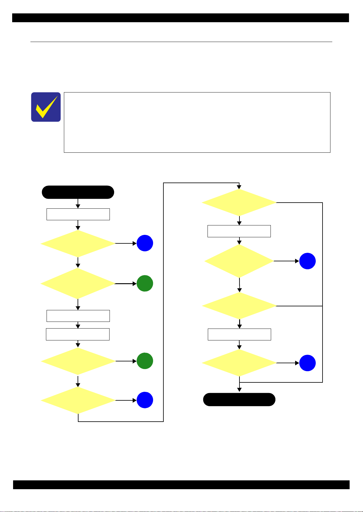
This flowchart is compiled based on the following contents.
• Our experience regarding the quality problem
• ESK’s repair data
• Printer Mechanism specification for L1455/ET-16500
If the reason for the return is evident, first check the phenomenon user claims recurs,
then proceed to the troubleshooting.
5
What is returned reason?
2
Standby condition
3
Is printing operation
finished without error?
Start
Turn on the printer
1
4
(p 11)
(p 11)
(p 11)
(p 12)
(p 12)
Copy an image
*: In case of “Not Trouble Found”, check fatal error code.
6
(p 12)
ADF/Scanner
unit failure
Printer failure only
Yes
No
Yes
No
Yes
Yes
No
Yes
Yes
No
No
No
No
Yes
Does printer turn on the
power?
Is Power-on sequence
finished without error?
Print check pattern
Is printing operation
finished without trouble?
Is scanning operation
finished without
trouble?
Is ADF operation finished
without trouble?
Copy an image by ADF
ADF failure?
Finish
*
1.1 Troubleshooting
This section describes the troubleshooting workflow.
1.1.1 Troubleshooting Workflow
The following page describes the troubleshooting workflow. Follow the flow when troubleshooting problems.
Revision A
Figure 1-1. Troubleshooting Workflow (1)
Troubleshooting Troubleshooting Workflow 10
Confidential
Page 11

Epson L1455 / ET-16500 Revision A
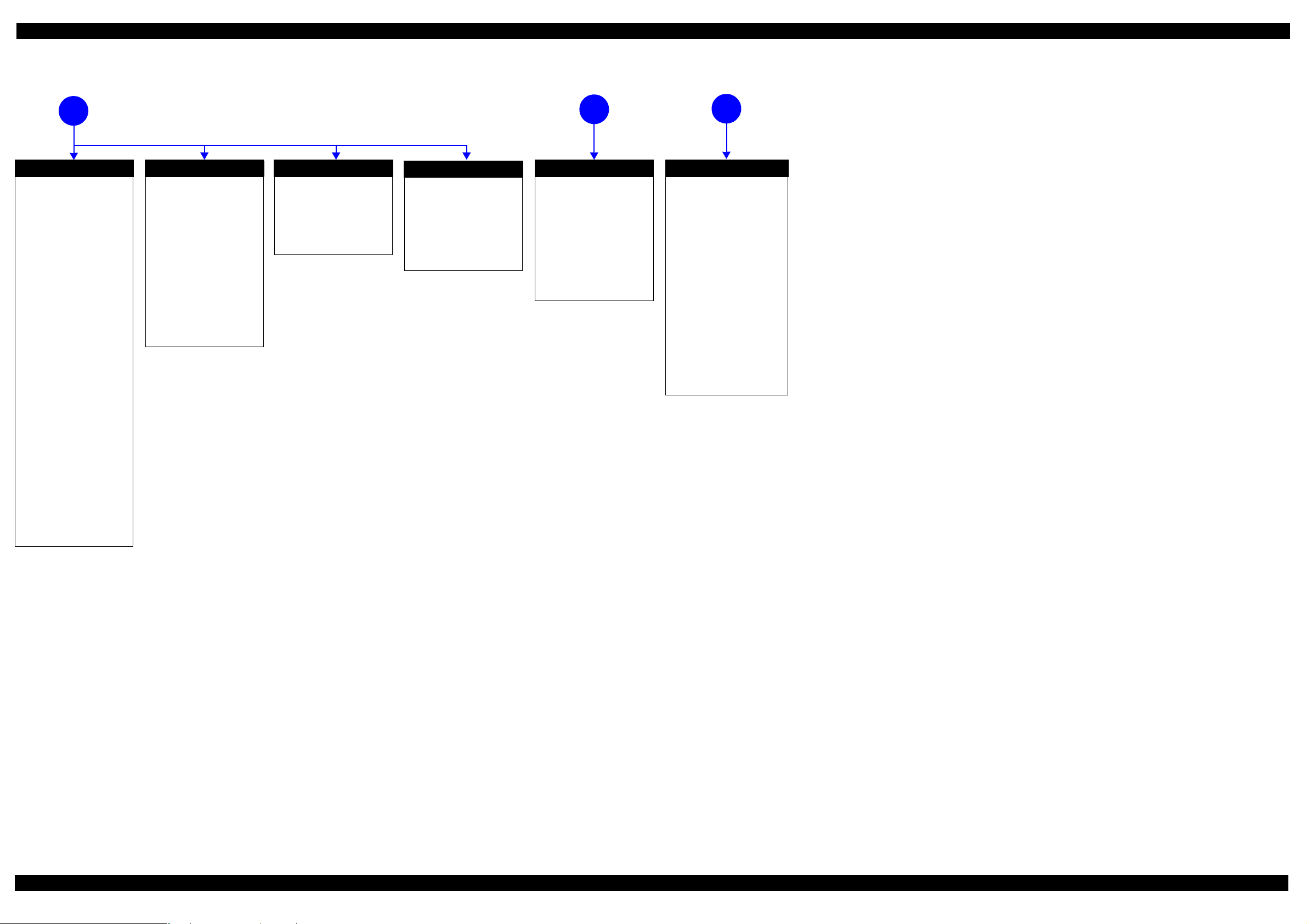
The power-on
1
sequence does not
start (p 10)
No Power
[Presumable Cause]
• Power Supply Unit
damage
• Main Board damage
• Panel Unit damage
[Major Troubleshooting]
• Power Supply Unit
replacement
• Main Board
replacement
• Panel Unit replacement
* : If the printer can turn on but turns
off right away, the protection
circuit may cut off the power due
to an error such as a circuit
failure.
*
Please refer to " 1.3 Fatal Error
Code List (p15)"for
troubleshooting.
2
Fatal error
Error is indicated during
power-on sequence (p 10)
Maintenance error
[Occurrence Condition]
This error occurs when
maintenance counter in
EEPROM exceeds the specified
value.
[Major Occurrence Timing]
• Power-on timing
• Print start timing
• Paper eject timing
• Cleaning timing
• Ink cartridge replacement
timing
[Major Troubleshooting]
• Replace Maintenance Box
• Paper Guide Lower Porous
Pad replacement
• Maintenance counter reset
(only Paper Guide Lower
Porous Pad)
No Maintenance Box error
[Occurrence Condition]
This error occurs when
Maintenance Box is not installed.
[Major Occurrence Timing]
• At power-on
• Maintenance Box monitoring
timing
[Major Troubleshooting]
Turn the printer off once and
install Maintenance Box again,
and turn the power on.
Maintenance Box detection
[Occurrence Condition]
This error occurs when
Maintenance Box data is incorrect
or it is not recognized correctly.
[Major Occurrence Timing]
• Power-on timing
• Maintenance Box replacement
• Maintenance Box monitoring
[Major Troubleshooting]
• Remove and reinstall
• Maintenance Box replacement
• Relay Board CSIC Terminal
• Relay Board Assy replacement
• Relay Board FFC replacement
• Main Board replacement
error
timing
timing
Maintenance Box
replacement
Ink End error
[Occurrence Condition]
This error occurs when ink in Ink
counter reaches ink end level.
[Major Occurrence Timing]
• Power-on timing
• Print start timing
• Print timing
• Cleaning timing
[Major Troubleshooting]
Refill ink and reset ink counter
by panel.
Cover open error
[Occurrence Condition]
This error occurs when Scanner
Unit (Printer Cover) is open.
[Major Occurrence Timing]
• At power-on
• During printing
[Major Troubleshooting]
• Close Scanner Unit (Printer
Cover) replacement
• Scanner Unit (Printer Cover)
replacement
• Cover Open Sensor
replacement
• Main Board replacement
Paper Jam error
Please refer to " Paper Jam
error".
CR Fixing Tape error
[Occurrence Condition]
This error occurs if a paper jam
occurs during the power-on
sequence before initial ink
charge.
[Major Occurrence Timing]
Power-on timing
(before initial ink charge)
[Major Troubleshooting]
Open the scanner unit and
remove the CR fixing tape.
Error is indicated during printing nozzle check pattern (p 10)
3
Paper Jam error
[Occurrence Condition]
This error occurs when top/bottom of
paper is not detected by PE Sensor in the
specified steps of paper feeding
operation correctly.
[Major Occurrence Timing]
• Power-on timing
• Paper loading timing
• Paper eject timin g
• Duplex print timing
[Major Troubleshooting]
1 remove the jammed paper by opening
Scanner Unit or Printer Cover.
2 Push “Start” button.
3 If not resolved by 2), check the
following.
• Foreign material, bits of paper
• Part come-off
• PE Lever
• PE Sensor
• Float of Paper Guide Front Porous
Pad
•Main Board
• PW Sensor
[NOTE]
* If an error occurs during printing, the
page where the error occurred is skipped
and the printing resumes from the next
page.
* If an error occurs during duplex
printing, the following are performed.
• If an error occurs during the front
face of duplex printing, the page
where the error occurred and the
next page are skipped and the
printing resumes from the page
after the next.
• If an error occurs during the back
face of duplex printing, the page
where the error occurred is skipped
and the printing resumes from the
next page.
No Paper error
[Occurrence Condition]
This error occurs when top of
paper is not detected by PE Sensor
in the specified steps of paper
loading operation correctly.
[Major Occurrence Timing]
Paper loading timing
[Major Troubleshooting]
1 Put paper in cassette and push
“START” button.
2 If a paper stops before reaching
PE Sensor, remove it and
check the paper condition.
3 A) If no damage on the paper, s et
edge guide correctly after
putting paper in ca ssette and
push “PRINT” button again.
B) If damage on the paper, check
foreign materials / parts come off / parts transforma tion in
paper path.
4 If not resolved by 3-A) & 3-B),
check the following.
• Pickup Roller
• Duplex Unit
• PE Sensor
• Main Board
• PF Motor
• Casette Assy
Double Feed error
[Occurrence Condition]
This error occurs on the following
cases.
• A paper is ejected without
printing during paper loading
operation.
• Actual paper length is longer
than theoretical one.
[Major Occurrence Timing]
Paper loading timing
[Major Troubleshooting]
• PE Lever replacement
• PE Sensor replacement
• PW Sensor replacement
• Main Board replacement
[NOTE]
This error occurs only for manual
duplex print.
No Paper Cassette error
[Occurrence Condition]
This error occurs if one of the
cassettes is not installed.
[Major Occurrence Timing]
Paper loading timing
(Front loading)
[Major Troubleshooting]
Install the Cassette Assy.
Paper Size Unmatch error
[Occurrence Condition]
This error occurs when actual
paper size is not matched to
theoretical one.
[Major Occurrence Timing]
• Duplex print timing
• FAX data print timing
[Major Troubleshooting]
1 Put correct sized paper in
cassette, and push “START”
button.
2 If not resolved by step 1),
check the following points.
• PE Lever
•PE Sensor
• PW Sensor
• Main Board
Manual Tray No Paper error
[Occurrence Condition]
When printing from Manual Tray
(MSF unit), this error occurs if
paper is not loaded at the time of
data transmission.
[Major Occurrence Timing]
Paper loading timing
(Rear loading)
[Major Troubleshooting]
• Put paper in the Manual Tray
(MSF unit).
• PE Sensor replacement
• PW Sensor replacement
• Main Board replacement
Manual Feed Request error
[Occurrence Condition]
This error occurs if the printer
cannot receive the manual feed
request.
[Major Occurrence Timing]
Paper loading timing
(Rear loading)
[Major Troubleshooting]
• Send the print data.
• Main Board replacement
Excessive Manual Feed Error
[Occurrence Condition]
This error occurs when the PE
Sensor detects paper before
manual feed or when paper is
inserted too much.
[Major Occurrence Timing]
Print start timing (Rear loading)
[Major Troubleshooting]
• Eject paper with panel
operation, and load paper
again.
• Main Board replacement
• PE Sensor replacement
• PE Lever replacement
Insufficient Manual Feed
[Occurrence Condition]
This error occurs during manual
feed if the PE Sensor detects
paper but the paper is not fed by
auto loading.
[Major Occurrence Timing]
Print start timing (Rear loading)
[Major Troubleshooting]
Eject paper with panel operation,
and load paper again.
error
Figure 1-2. Troubleshooting Workflow (2)
Appendix Troubleshooting Workflow 11
Confidential
Page 12
Epson L1455 / ET-16500 Revision A
Problems related to print result or during printing(p 10)
4
Poor Printing
[Phenomenon]
• Poor printing quality
• Ink stain on paper
• Dot missing
• Paper eject without printing
[Presumable Cause]
• Driver / Panel mis-setting
• Contamination of CR scale
• Contamination of Printhead
Cover
• Printhead damage
• Ink clogging of Printhead
• Contamination on Cap Unit /
Wiper of Ink system Assy
• Ink system Assy damage
• Float of Paper Guide Front
Porous Pad
• Narrow PG
• PE Lever damage
• PE Sensor damage
• PW Sensor damage
• Ink tank ventilation film gets
wet
• Different kinds of ink mixture
[Major Troubleshooting]
• Driver / Panel re-setting
• CR Scale replacement
• Printhead cover cleaning
• Printhead cleaning
• Ink cartridge replacement
• Printhead replacement
• Rubber cleaning of Cap Unit of
Ink system Assy
• Ink system Assy replacement
• Paper Guide Front Porous Pad
re-installation
• PG readjustment
• Printer Mechanism
replacement
• PE Lever replacement
• PE Sensor replacement
• PW Sensor replacement
• Ink tank Replacement
• Ink supply pathway
replacement or cleaning
Poor Paper Loading
[Presumable Cause]
• Use of 3rd party media
• Edge guide mis-setting
• Foreign material
• Part come-off
• Contamination of paper feed
roller (Duplex Unit)
• Cassette Assy damage
• Pickup Roller deterioration,
contamination
• Contamination of PF roller
[Major Troubleshooting]
• Recommendation of EPSON
media
• Edge guide re-setting
• Foreign material removal
• Part re-installat ion
• PF Roller replacement
• Cassette Assy replacement
• Pickup Roller replacement
Abnormal Noise
[Presumable Cause]
• Foreign material
• Insufficient grease
• Gear damage
[Major Troubleshooting]
• Foreign material removal
• Lubrication of grease
• Gear replacement
Blank Printing
[Presumable Cause]
• Ink tank ventilation film gets
wet
• Ink tube crumples
• Ink tube connection is
incomplete
[Major Troubleshooting]
• Ink tank replacement
• Ink tube re-installation or
replacement
Scanning cannot be
performed
5
successfully (p 10)
Scanner failure
[Presumable Cause]
• Contamination of Scanner
Glass
• Contamination of Document
Pad
• CIS Unit bonding failure
• CIS Unit damage
• Scanner Motor damage
[Major Troubleshooting]
• Scanner Glass cleaning
• Document Pad cleaning
• Document Pad replacement
• CIS Unit replacement
• Scanner Motor replacement
ADF does not operate
6
normally (p 10)
ADF failure
[Phenomenon]
• No paper feed
• Double feed
• Paper jam
• Paper skew
[Presumable Cause]
• Wear of Pickup Roller
• Wear of ADF Pad Assy
•Gear damage
• ADF Motor damage
• Contamination of Scanner Glass
• ADF Paper Support Assy
damage
• Foreign material
• ADF Cover Assy damage
• Wear of EJ Roller
• ADF Sensors damage
[Major Troubleshooting]
• ADF Cover Assy replacement
• ADF Pad Assy replacement
• Scanner Glass cleaning
• ADF Paper Support Assy
replacement
• Foreign material removal
• ADF Unit replacement
Figure 1-3. Troubleshooting Workflow (3)
Appendix Troubleshooting Workflow 12
Confidential
Page 13

Epson L1455 / ET-16500 Revision A
1.2 Power-On Sequence
This section describes the power-on sequences for this product. The preconditions are as follows.
Normal power-on sequence (See Table 1-1.)
Turning on the printer after turning it off without an error.
Initial ink charge has finished and every cartridge has sufficient ink.
No paper on the paper path.
The Printhead is capped by the cap of the Ink System and the CR Lock is engaged normally.
Table 1-1. Normal Power-on Sequence
Operation
1. Printhead initialization
1-1.Initializes the Printhead.
*3
2. Checking for waste ink overfl ow
2-1.Checks the waste ink counter if the waste ink overflow is occurring.
*1
CR Unit/PF Roller
movement and position
HP
CRUnit
APGLever CRLock
*
2
0130
0130 HP
3. Avoiding deadlock sequence
*4
3-1.The CR Unit moves to the 0-digit side slowly and confirms it touches the Right Frame.
3-2.The CR Unit moves to the 80-digit side up to its home position.
3-3.The PF Motor rotates clockwise, and releases the CR lock.
4. Seeking the home position
4-1.The carriage moves to the 0-digit side slowly and confirms it touches the Right Frame.
4-2.By regarding the position where the CR Unit touches the Right Frame as the specified distance from the origin, the
home position is determined. Thereafter, the position of the CR Unit is monitored based on the information
provided by the CR Encoder.
4-3.The CR Unit slowly moves to its home position.
5. PF initialization
5-1.The CR Unit moves slowly about 3 cm to the 130-digit side.
5-2.The PF Roller rotates counterclockwise quickly.
0130 HP
0130 HP
0130 HP
0130 HP
0130 HP
0130 HP
0130 HP
0130 HP
5-3.The CR Unit moves to ASF trigger ON => OFF positions.
5-4.The PF Motor rotates clockwise for approx. one second.
5-5.The PF Roller rotates clockwise for about one second.
5-6.The PE sensor detects if paper exists and the PF Motor rotates clockwise for approx. 0.5 second.
*5
0130 HP
0130 HP
0130 HP
0130 HP
Appendix 13
Confidential
Page 14

Epson L1455 / ET-16500 Revision A
0130 HP
1Prior to Step 4-1 Initializes the APG Lever.
2 Prior to Step 4-2
The CR Unit evacuates to the 130-digit side once, and the PF Roller rotates clockwise once, then the cap unit of
the Ink System is lowered, and then the CR Unit touches the Right Frame once again for confirmation.
3Prior to Step 4-3
The CR Unit moves to its CR Lock Position (130-digit side), and the PF Roller rotates
counterclockwise to engage the CR Lock. Then the CR Unit touches the CR Lock for confirmation.
4 Prior to Step 5-5 Initializes the APG unit (set to PG1 position).
5Prior to Step 7-1 Measurement of the CR Motor
Table 1-1. Normal Power-on Sequence
CR Unit/PF Roller
movement and position
*
2
0130 HP
6. Low temperature operation sequence
6-1.The CR Unit returns its home position.
*6
Operation
*1
6-2.The CR Unit moves between around the switch lever and in front of the Left Frame two times.
7. PF measurement and PW sensor initialization
7-1. The CR Unit slightly moves to the 0-digit side.
7-2.The carriage moves to the VHCheck position (130-digit side) quickly and stops; meanwhile the voltage values
detected by the PW sensor at the specified three points are recorded. At the same time, the PF Motor rotates
clockwise and measures the load.
7-3.The CR Unit detects the voltage of the PW sensor at the carriage stop position (the black area at the Paper Guide
Front).
7-4.The CR Unit returns near its home position. At the same time, the PF Motor rotates clockwise and measures the
load.
8. Detecting ink cartridge and initializing ink system
*7
8-1.The CR Unit slowly returns to its home position.
8-2.To check the operation of the PIS Sens or and to detect ink, the CR Unit moves back and for th between th e CR Unit
and near the APG Lever for two times.
9. CR lock setting
9-1.The CR Unit moves to its home position.
0130 HP
0130 HP
0130 HP
0130 HP
0130 HP
0130 HP
0130 HP
9-2.The PF Roller rotates counterclockwise to lock the CR Unit with the CR Lock.
Note *1: The rotation directions of the PF Motor are as follows.
Clockwise: Paper is fed normally
Counterclockwise: Paper is fed backward
*2: The conditions of the CR lock are as follows.
Red CR lock is set
White CR lock is released
*3: If it cannot be initialized, the fatal error occurs.
*4: Confirm that the CR lock is not get stuck in the gap of the carriage or any other parts preventing the carriage from moving.
*5: Eject paper if any.
*6: Executed when the detected temperature is under 5
o
C (41oF) by the thermistor on the Printhead.
*7: The empty suction operation may occur depending on situations.
The power-on sequence shown in Table 1-1 is the sequence for when the previous power-off is
complete normally as indicated in the conditions. If the previous power-off ends abnormally,
operations including initialization of APG and such are performed in the following steps.
0130 HP
Appendix 14
Confidential
Page 15

Epson L1455 / ET-16500 Revision A
1.3 Fatal Error Code List
This section describes the fatal error code and the possible cause for this product.
Fatal error list
Table 1-2. Fatal Error List (Printer)
Error type
ADF/Scanner
Error
code
01H ADF PID excess speed error
02H ADF PID reverse e r ror
03H ADF PID lock error • ADF Encoder failure (contaminated/detached scale, Encoder Board
04H
05H ADF PID excess load error
06H ADF PID
09H ADF BS+ excess speed error
0AH ADF BS+ reverse error
0BH ADF BS+ lock error • ADF Encoder failure (contaminated/detached scale, Encoder Board
0DH ADF BS+ excess load error
0EH ADF BS+ driving time er ro r • Main Board failure
10H HP detection error
11H
12H
13H
14H Measurement failure error • Scanner drive mechanism was overloaded.
ADF PID acceleration lock detection
error
Contact detection distance exceeded
error
Opposite side contact detection distance
exceeded error
Opposite side wrong contact detection
distance error
Error name Possible cause
• ADF Encoder failure (contaminated/detached scale, Encoder Board
failure)
• Motor driver failure (Main Board failure)
• ADF Encoder failure (contaminated/detached scale, Encoder Board
failure)
• Paper jam
failure)
• ADF Motor failure
• Paper jam
• Cable disconnection
DRIVING TIME ERROR • Main Board failure
• ADF Encoder failure (contaminated/detached scale, Encoder Board
failure)
• Motor driver failure (Main Board failure)
• ADF Encoder failure (contaminated/detached scale, Encoder Board
failure)
• Paper jam
failure)
• ADF Motor failure
• ADF drive overload (paper jam/foreign object)
• Cable disconnection
• CIS Unit failure
• Scanner Housing failure
• Main Board failure
• CIS Unit failure
• Scanner Housing failure (Including wrong attachment of the origin mark)
• Main Board failure
• Scanner FFC failure / Scanner FFC connection failure
• Scanner Motor failure / Scanner Motor connection failure
• CIS Unit failure
• Scanner Housing failure (Including wrong attachment of the origin mark)
• Main Board failure
• Scanner FFC failure / Scanner FFC connection failure
• Scanner Motor failure / Scanner Motor connection failure
• CIS Unit failure
• Scanner Housing failure (Including wrong attachment of the origin mark)
• Main Board failure
• Scanner FFC failure / Scanner FFC connection failure
• Scanner Motor failure / Scanner Motor connection failure
Appendix 15
Confidential
Page 16

Epson L1455 / ET-16500 Revision A
Table 1-2. Fatal Error List (Printer)
Error type
ADF/Scanner
Printer
Error
code
20H LED light error
30H Option error • Main Board failure
36H Paper jam error
41H FB PID excess speed
42H FB PID reverse
43H FB PID lock • ADF Encoder failure (contaminated/detached scale, Encoder Board
44H FB PID acceleration lock
45H FB PID excess load
46H FB PID driving time • Main Board failure
49H FB BS+ excess speed
4AH FB BS+ reverse
4BH FB BS+ lock • ADF Encoder failure (contaminated/detached scale, Encoder Board
4DH FB BS+ excess load
4EH FB BS+ driving time • Main Board failure
51H Automatic judgment fatal error 1
52H Automatic judgment fatal error 2
53H Automatic judgment fatal error 3
54H Automatic judgment fatal error 4
55H Automatic judgment fatal error 5
60H HP error
67H APG target position acquisition error
68H Contact error at valve initialization
69H Contact error at I/S clutch operation
6BH PF runaway error
7FH Inspection mode error ---
8DH Factor error other than printer device
8EH Driver mismatch error An unsupported driver was used.
8FH EEPROM verify error (by command) ---
93H PE Sensor error
Error name Possible cause
• CIS Unit failure
• Main Board failure
• Paper jam
• Foreign object
• ADF Encoder failure (contaminated/detached scale, Encoder Board
failure)
• Motor driver failure (Main Board failure)
• ADF Encoder failure (contaminated/detached scale, Encoder Board
failure)
• Paper jam
failure)
• ADF Motor failure
• ADF drive mechanism overload (assembling failure, lubrication failure)
• Cable disconnection
• ADF Encoder failure (contaminated/detached scale, Encoder Board
failure)
• Motor driver failure (Main Board failure)
• ADF Encoder failure (contaminated/detached scale, Encoder Board
failure)
failure)
• ADF Motor failure
• ADF drive mechanism overload (assembling failure, lubrication failure)
• Cable disconnection
---*
• Paper jam
• Foreign object
• Deformation of the Main Frame
• APG Motor failure
• APG Sensor failure
• Main Board failure
• Ink system failure
• Main Board failure
• PF Encoder failure
• Motor driver failure
*
This error occurs if the printer becomes a fatal error status due to a failure of
parts other than the printer such as the scanner or ADF.
*
• PE Sensor failure
• Main Board failure
Appendix 16
Confidential
Page 17

Epson L1455 / ET-16500 Revision A
Table 1-2. Fatal Error List (Printer)
Error type
Printer
Error
code
97H
9AH Circuit error (include blowout of a fuse)
9BH Transistor temperature error
9CH X-Hot detect error (pre printing)
9DH X-Hot detect error (after flushing)
9EH Head temperature error
9FH No print inspection mode error ---
D1H ASF PID excess load error
D2H ASF PID excess speed error
D3H ASF PID reverse error
D4H ASF PID lock error
D6H ASF PID excess torque limitation error
D8H ASF load position reverse error
D9H ASF load position excess speed error
DAH ASF load position excess load error
DEH ASF PID driving time error
DFH ASF loa d position driving time error
E1H CR PID excess load error
E2H CR PID excess speed error
E3H CR PID reverse error
Head drive circuit VBS over-voltage
error
Error name Possible cause
• Head FFC failure
• Main Board failure
• Main Board failure
• Printhead failure
• Main Board failure
• ASF Encoder failure (contaminated/detached scale, Encoder Board
failure)
• ASF Motor failure
• Pickup Roller (2nd cassette) drive mechanism overload (paper jam/
foreign object)
• Cable disconnection
• ASF Encoder failure (contaminated/detached scale, Encoder Board
failure)
• Motor driver failure (Main Board failure)
• ASF Encoder failure (contaminated/detached scale, Encoder Board
failure)
• Paper jam
• ASF Encoder failure (contaminated/detached scale, Encoder Board
failure)
• ASF Motor failure
• Pickup Roller (2nd cassette) drive mechanism overload (paper jam/
foreign object)
• Cable disconnection
Pickup Roller (2nd cassette) drive mechanism overload (paper jam/foreign
object)
• ASF Encoder failure (contaminated/detached scale, Encoder Board
failure)
• Paper jam
• ASF Encoder failure (contaminated/detached scale, Encoder Board
failure)
• Motor driver failure (Main Board failure)
• ASF Encoder failure (contaminated/detached scale, Encoder Board
failure)
• ASF Motor failure
• Pickup Roller (2nd cassette) drive mechanism overload (paper jam/
foreign object)
• Cable disconnection
• Main Board failure
• CR Encoder failure (contaminated/detached scale, Encoder Board failure)
• CR Motor failure
• Carriage overload error (paper jam/foreign object)
• Cable disconnection
• CR Encoder failure (contaminated/detached scale, Encoder Board failure)
• Motor driver failure (Main Board failure)
• Tooth skip of the CR Timing Belt
• Improper tension of the CR Timing Belt
• CR Encoder failure (contaminated/detached scale, Encoder Board failure)
• Tooth skip of the CR Timing Belt
• Improper tension of the CR Timing Belt
• Paper jam
*
Appendix 17
Confidential
Page 18

Epson L1455 / ET-16500 Revision A
Table 1-2. Fatal Error List (Printer)
Error type
Printer
Error
code
E4H CR PID lock error
E5H CR PID speed fall error
E8H CR load position reverse error
E9H CR load position excess speed error
EAH CR load position excess load error
EBH APG driving time error • Main Board failure
ECH APG excess speed error
EEH CR PID driving time error
EFH CR load position driving time error
F1H PF PID excess load error
F2H PF PID excess spee d error
F3H PF PID reverse error
F4H PF PID lock error
F6H PF PID excess torque limitation error ---
F8H PF load position reverse error
F9H PF load position excess speed error
Error name Possible cause
• CR Encoder failure (contaminated/detached scale, Encoder Board failure)
• CR Motor failure
• Carriage overload error (paper jam/foreign object)
• Cable disconnection
• CR Encoder failure (contaminated/detached scale, Encoder Board failure)
• Motor driver failure (Main Board failure)
• Tooth skip of the CR Timing Belt
• Improper tension of the CR Timing Belt
• Paper jam
• CR Encoder failure (contaminated/detached scale, Encoder Board failure)
• Tooth skip of the CR Timing Belt
• Improper tension of the CR Timing Belt
• Paper jam
• CR Encoder failure (contaminated/detached scale, Encoder Board failure)
• Motor driver failure (Main Board failure)
• Tooth skip of the CR Timing Belt
• Improper tension of the CR Timing Belt
• CR Encoder failure (contaminated/detached scale, Encoder Board failure)
• CR Motor failure
• Carriage overload error (paper jam/foreign object)
• Cable disconnection
• APG Sensor failure
• APG Motor failure
• Tooth skip of APG drive gear
• Main Board failure
• PF Encoder failure (contaminated/detached scale, Encoder Board failure)
• PF Motor failure
• PF drive mechanism overload (paper jam/foreign object)
• Cable disconnection
• PF Encoder failure (contaminated/detached scale, Encoder Board failure)
• Motor driver failure (Main Board failure)
• Tooth skip of the PF Timing Belt
• Improper tension of the PF Timing Belt
• PF Encoder failure (contaminated/detached scale, Encoder Board failure)
• Tooth skip of the PF Timing Belt
• Improper tension of the PF Timing Belt
• Paper jam
• PF Encoder failure (contaminated/detached scale, Encoder Board failure)
• PF Motor failure
• PF drive mechanism overload (paper jam/foreign object)
• Cable disconnection
• PF Encoder failure (contaminated/detached scale, Encoder Board failure)
• Tooth skip of the PF Timing Belt
• Improper tension of the PF Timing Belt
• PF Encoder failure (contaminated/detached scale, Encoder Board failure)
• Motor driver failure (Main Board failure)
• Tooth skip of the PF Timing Belt
• Improper tension of the PF Timing Belt
*
Appendix 18
Confidential
Page 19

Epson L1455 / ET-16500 Revision A
Table 1-2. Fatal Error List (Printer)
Error type
Printer
Note "*": Not occurs except in manufacturing process.
Error
code
FAH PF load position excess load error
FEH PF PID driving time error
FFH PF load position driving time error
Error name Possible cause
• PF Encoder failure (contaminated/detached scale, Encoder Board failure)
• PF Motor failure
• PF drive mechanism overload (paper jam/foreign object)
• Cable disconnection
• Main Board failure
Appendix 19
Confidential
Page 20

Epson L1455 / ET-16500 Revision A
Power
[3]
Moves up menu selection.
[Color]
Enter
[6]
Moves down menu selection.
Power on button
[6] button
[4] button
1.4 Status sheet
This section describes the Status sheet for this product.
This product can print the three kind of status sheet, and you can confirm the following
information.
• C o nfiguration Status Sheet
• Supply Status Sheet
• Usage History Sheet
This product has Non-disclosed information to user.
This information can be displayed on the Status sheet by starting the product with the
Service Support Mode.
1.4.1 Start method of Service Support Mode
During in the Service Support Mode, operations such as menu selection can be done by
pressing the following buttons on the panel.
Figure 1-4. Panel Operation in Service Support Mode
1. From a power off status, push the following button until the message is displayed on LCD.
L1455/ET-16500
2. Select “2.Status Sheet Print Mode” from the Service Support menu.
3. The product starts as usual.
4. Print the Status sheets.
Appendix Start method of Service Support Mode 20
Confidential
Page 21
Epson L1455 / ET-16500 Revision A
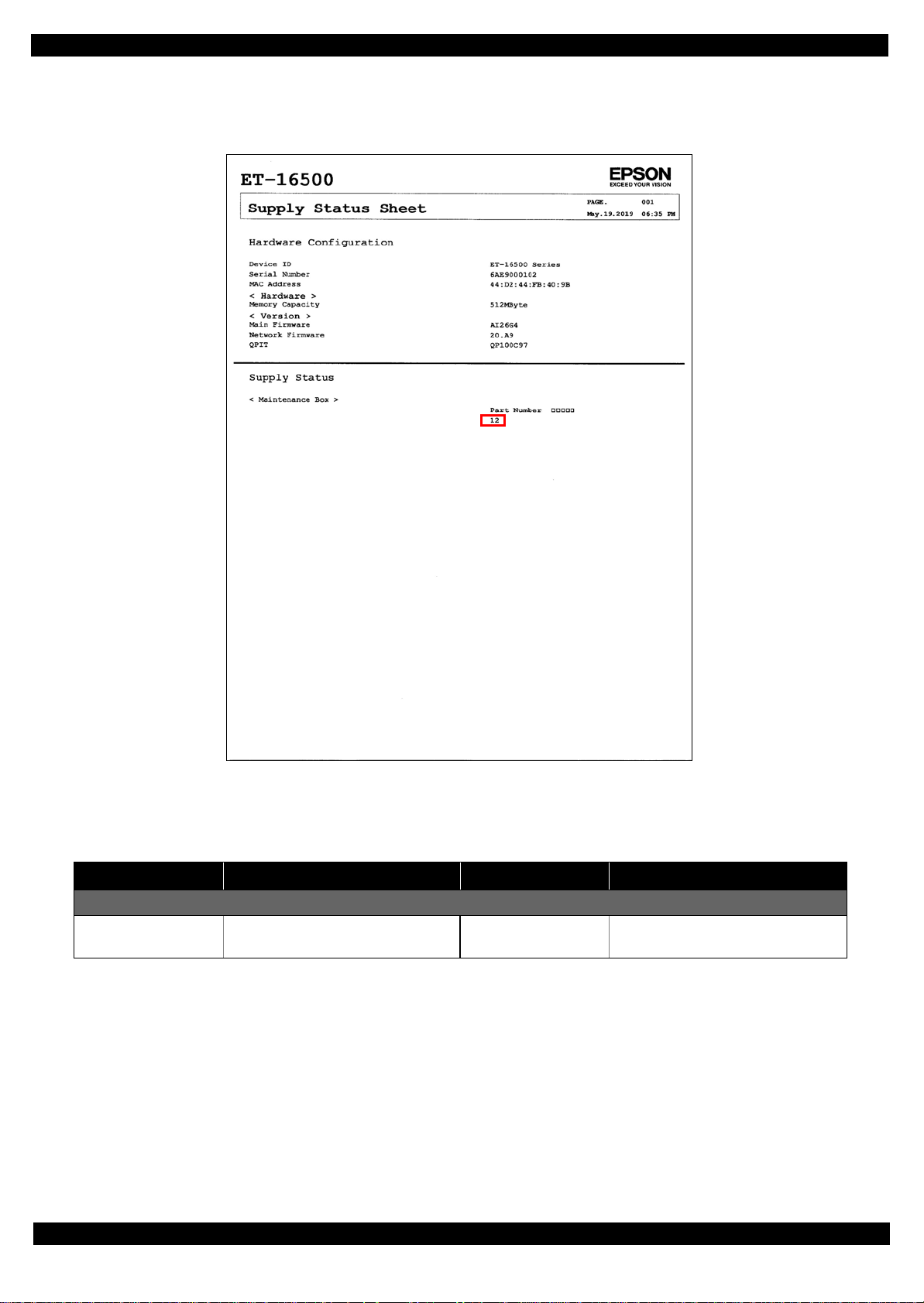
1.4.2 Description of Status sheet (Non-disclosed information to user)
Supply Status sheet
Table 1-3. Supply Status sheet (Non-disclosed information to user)
Item Content Item Content
Consumable information <Maintenance Box>
Maintenance Box
residual quantity
Residual quantity information of the
Maintenance Box
Appendix Description of Status sheet (Non-disclosed information to user) 21
Confidential
Page 22

Epson L1455 / ET-16500 Revision A
Usage History Sheet
Table 1-4. Usage History Sheet (Non-disclosed information to user)
Item Content Item Content
Number of Sheets Loaded
From Cassette 1 Number of shee ts loaded from 1st
cassette
From Paper Feed Slot Number of sheet loaded from paper
feed slot.
Number of sheets scanned
From ADF Number of sheets scanned from ADF
Unit.
Number of Replacement
Maintenance Box Number of replacement of
Maintenance Box.
From Cassette 2 Number of loaded from 2nd cassette
From Scanner Glass Number of sheets scanned from
Scanner Glass.
Appendix Description of Status sheet (Non-disclosed information to user) 22
Confidential
Page 23

CHAPTER 2
DISASSEMBLY/REASSEMBLY
Confidential
Page 24

Epson L1455/ET-16500 Revision A
2.1 Overview
This chapter describes procedures for disassembling the main parts/units of L1455/ET-16500. Unless otherwise
specified, disassembled parts/units can be reassembled by reversing the disassembly procedure. See the cautions
or tips for disassembly/reassembly described in "2.4 Detailed Disassembly/Reassembly Procedure for each Part/
Unit (p55)".
Read the " Safety Precautions (p3)" before disassembling and reassembling.
When you have to remove units or parts that are not described in this chapter, see the exploded diagrams of SPI
(Service Parts Information).
2.1.1 Tools
Use only specified tools to avoid damaging the printer.
Name Availability EPSON Part Code
(+) Phillips screwdriver #1 O 1080530
(+) Phillips screwdriver #2 O --Flathead screwdriver O --Flathead Precision screwdriver #1 O --Tweezers O --Longnose pliers O --Nippers O --Teflon tape No.903UL 1 1706715
Tube clip 4 Commercially available
Injector 4 Commercially available
Containers 4 Commercially available
Note 1: Some of the tools listed above are commercially available.
2: EPSON provides the tools listed with EPSON part code.
2.1.2 Jigs
Name Q’ty EPSON Part Code
Thickness gauge (1.6mm) 1 Commercially available
Thickness gauge (1.42mm) 1 Commercially available
Thickness gauge (1.52mm) 1 Commercially available
Thickness gauge (1.72mm) 1 Commercially available
Thickness gauge (1.82mm) 1 Commercially available
Disassembly/Reassembly Overview 24
Confidential
Page 25

Epson L1455/ET-16500 Revision A
2.1.3 Standard Operation Time for servicing the product
The following are the standard operation time for servicing the product. Those are based on the MTTR result
measured using a prototype. Perform servicing referring to this operation standard time.
The underlined parts/units are supplied as After Service Parts.
Table 2-1. Standard Operation Time for servicing the product
Time
Parts/Unit
Replacement
USB Cover 0:44 --- 0:44
Pickup Holder 1st 0:23 --- 0:23
Pickup Roller 1st
Pickup Holder 2nd 0:10 --- 0:10
Pickup Roller 2nd
Paper Stopper Assy 2nd 0:50 --- 0:50
Duplex Unit Cover Assy 0:50 4:43 5:33
MSF Unit 1:01 4:43 5:44
MSF Stopper Belt 1:27 --- 1:27
Assist Roller Holder Assy 1:04 4:43 5:47
Decoration Plate 0:45 --- 0:45
Ink Tube Shield 0:57 --- 0 :5 7
Panel Unit
Speaker Cover 2:12 --- 2:12
Speaker 2:12 --- 2:12
Lower Case
ADF Pad Assy
Document Pad
MSF Cover
ADF Cover Assy
LD Shaft 0:42 --- 0:42
ADF LD Assy
ADF/Scanner Unit 9:28 --- 9:28
ADF Unit
ADF Cover Right
ADF Decoration Plate Front
ADF Decoration Plate Rear
ADF Cover Front
ADF Cover Rear
ADF Paper Support Cover 17:13 --- 17:13
Paper Support Encoder Sensor 17:45 --- 17:45
ADF Paper Support Assy
ADF Motor Unit 23:59 0:46 24:45
ADF Frame Base 23:59 --- 23:59
Scanner Unit
Scanner Housing Upper Assy 17:42 --- 17:42
Scanner FFC Cover 18:43 --- 18:43
0:53 --- 0:53
0:23 --- 0:23
1:50 0:26 2:16
1:14 --- --0:19 --- 0:19
0:14 --- 0:14
0:06 --- 0:06
0:31 --- 0:31
1:14 --- 1:14
14:42 0:46 15:28
15:03 --- 15:03
14:55 --- 14:55
14:52 --- 14:52
17:48 --- 17:48
16:52 --- 16:52
19:00 --- 19:00
14:42 0:58 15:40
Adjustment/
Inspection
Total
Disassembly/Reassembly Overview 25
Confidential
Page 26

Epson L1455/ET-16500 Revision A
Table 2-1. Standard Operation Time for servicing the product
Time
Parts/Unit
Replacement
Scanner Motor Assy 19:18 0:58 20:16
CIS Module 20:22 --- 20:22
Hinge Left 9:52 --- 9:52
Hinge Right 9:52 --- 9:52
Housing Upper Assy 18:03 --- 18:03
Duplex Unit Cover Open Sensor 18:27 --- 18:27
Housing Upper
Housing Front Assy 20:44 --- 20:44
Cover Open Sensor
Housing Front
Main Board Unit
Cable Support Plate 28:00 --- 28:00
Wireless LAN Module
Shield Plate Upper (w/Wireless LAN Module) 28:31 --- 28:31
Main Board (read OK)
Main Board (read NG)
Shield Plate Lower (w/Cable Support Plate) 30:02 --- 30:02
Stacker Assy
FAX Unit
FAX Shield Plate /FAX Connector Cover 22:09 --- 2 2:09
FAX Board
Power Supply Unit
Clamp Tube
Ink system Assy
Gear Cover 22:34 --- 22:34
Holder Board
Printhead Cover 21:15 --- 21:15
Printhead
Pickup Assy 1st
Relay Board FFC Guide 21:28 --- 21:28
Holder Cam Assy
Waste Ink Tray Cover 22:06 --- 22:06
Relay Board Assy
Relay Board CSIC Terminal 23:11 --- 23:11
Relay Board 23:04 --- 23:04
Relay Board Holder 23:27 --- 23:27
Waste Ink Tray Holder 23:32 --- 23:32
CR Scale
CR Driven Pulley Assy 22:32 1:00 23:32
APG Driven Shaft Support Plate 22:33 --- 22:33
APG Unit Support Plate 21:12 --- 21:12
APG Driven Shaft 25:24 --- 25:24
18:48 --- 18:48
21:05 --- 21:05
21:27 --- 21:27
27:28 --- 27:28
28:16 --- 28:16
30:02 2:25 32:27
30:02 17:32 47:34
20:51 --- 20:51
21:22 --- 21:22
22:09 --- 22:09
22:01 3:26 25:27
20:59 --- 20:59
22:10 --- 22:10
21:44 --- 21:44
23:45 23:44 47:29
23:57 --- 23:57
22:05 --- 22:05
22:48 --- 22:48
21:38 --- 21:38
Adjustment/
Inspection
Total
Disassembly/Reassembly Overview 26
Confidential
Page 27

Epson L1455/ET-16500 Revision A
Table 2-1. Standard Operation Time for servicing the product
Time
Parts/Unit
Replacement
Paper Guide Upper Assy 27:13 8:15 35:28
PF Sensor 28:06 --- 28:06
CR Guide Frame Assy (w/CR Unit) 33:42 16:24 50:06
Front Frame 35:04 7:45 42:49
PG Adjustment Cam Right 34:14 5:40 39:54
CR Scale Support Plate 34:10 --- 34:10
PG Adjustment Cam Left 34:44 5:40 40:24
Star Wheel Assy
Star Wheel Frame
Star Wheel Holder
Frame Base 2nd Assy
ASF Motor Assy 47:22 0:35 47:57
Spur Gear 16 47:26 --- 47:26
Pickup Assy 2nd 49:10 --- 49:10
Paper Stopper Assy 1st 46:58 --- 46:58
One Way Clutch Gear 39:22 --- 39:22
Main Frame Unit
PF Motor 48:16 0:26 48:42
CR Motor 47:54 0:41 48:35
PE Lever 52:00 0:38 52:38
Paper Guide Middle 52:17 --- 52:17
PE Sensor 52:32 0:38 53:10
Paper Guide Lower Porous Pad
APG Unit 48:05 --- 48:05
Tank Cap
Adapter Cover
Ink Tank Cover
Ink End Sensor Lumiror 0:34 --- 0:34
Ink Tank Assy
Ink Tank Housing Lower
Ink Tank Housing Upper
Ink End Sensor Board
Ink Tank Pourous Pad
Ink End Sensor Board Holder
Ink Tank (Black)
Ink Tank (Color)x3
Ink Supply Tube
Joint
Ink Adapter Tube Assy
Adapter (Black)
Adapter (Color)x3
Tube Guide Sheet
36:46 1:37 38:23
37:06 1:37 38:43
37:06 1:37 38:43
46:08 4:02 50:10
47:19 19:37 66:56
47:24 0:13 47:37
0:08 --- 0:08
0:18 --- 0:18
0:06 --- 0:06
6:01 --- 6:01
6:46 --- 6:46
7:42 --- 7:42
8:17 --- 8:17
7:52 --- 7:52
8:52 --- 8:52
9:55 --- 9:55
9:55 --- 9:55
9:03 --- 9:03
7:51 --- 7:51
12:19 --- 12:19
12:32 --- 12:32
12:58 --- 12:58
12:29 --- 12:29
Adjustment/
Inspection
Total
Disassembly/Reassembly Overview 27
Confidential
Page 28

Epson L1455/ET-16500 Revision A
Table 2-1. Standard Operation Time for servicing the product
Time
Parts/Unit
Replacement
Ink Adapter Tube (Black1) 12:29 --- 12:29
Ink Adapter Tube (Black2)
Ink Adapter Tube (Color1)
Ink Adapter Tube (Color2) 13:39 --- 13:39
Joint (Black) 12:32 --- 12:32
Joint (Color) 12:39 --- 12:39
Tube Clamp(x4)
Tube Guide 12:44 --- 12:44
Tube Guide Cover
12:59 --- 12:59
12:54 --- 12:54
13:09 --- 13:09
12:23 --- 12:23
Adjustment/
Inspection
Total
Disassembly/Reassembly Overview 28
Confidential
Page 29
Epson L1455/ET-16500 Revision A
Ventilation film
Air hole
Cyan ink
Can’t judge by visual
evaluation
Ventilation film
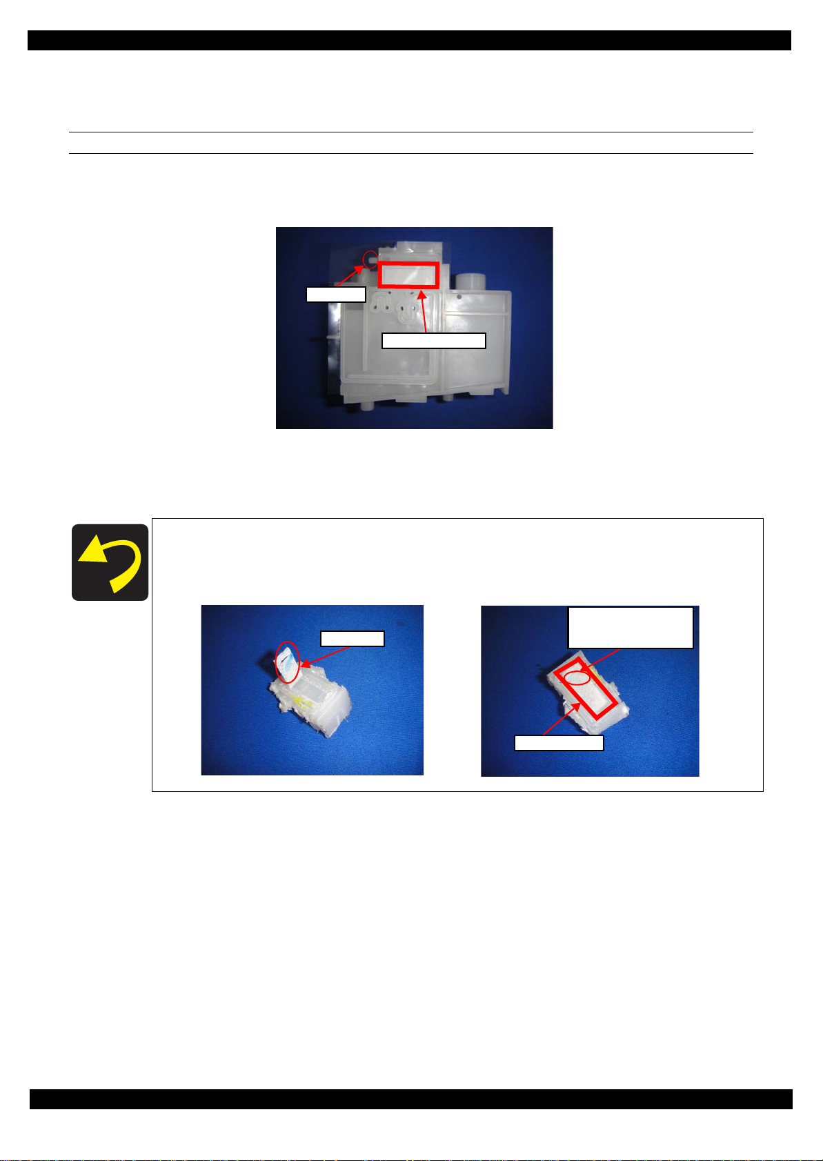
2.1.4 Checks and Precautions before Disassembling
2.1.4.1 Factors which Affect the Print Quality
VENTILATION FILM GETS WET
The ventilation film is under the sealing film of the ink tank unit. The atmosphere in the ink tank is vented to the
outside through this ventilation film in order to keep the ink supply to printer head stably. If the ventilation film
gets wet, the atmosphere in the ink tank can't be vented to the outside and maybe have a trouble for printing.
Figure 2-1. Ventilation film
How to check the ventilation film gets wet
If the ventilation gets wet, the tank should be replaced. Because we can’t judge the
ventilation film wet by visual evaluation, we can check the air chamber where the ink
reach.
Disassembly/Reassembly Overview 29
Confidential
Page 30
Epson L1455/ET-16500 Revision A
Ink Tank Assy
Ventilation Hole
Ink Tank Assy
OK
NG
If the ink reach the following air chamber (red area), the ventilation film is likely to be wet, so we recommend
that you disassemble the Ink Tank and confirm it.
Figure 2-2. Ventilation film gets wet
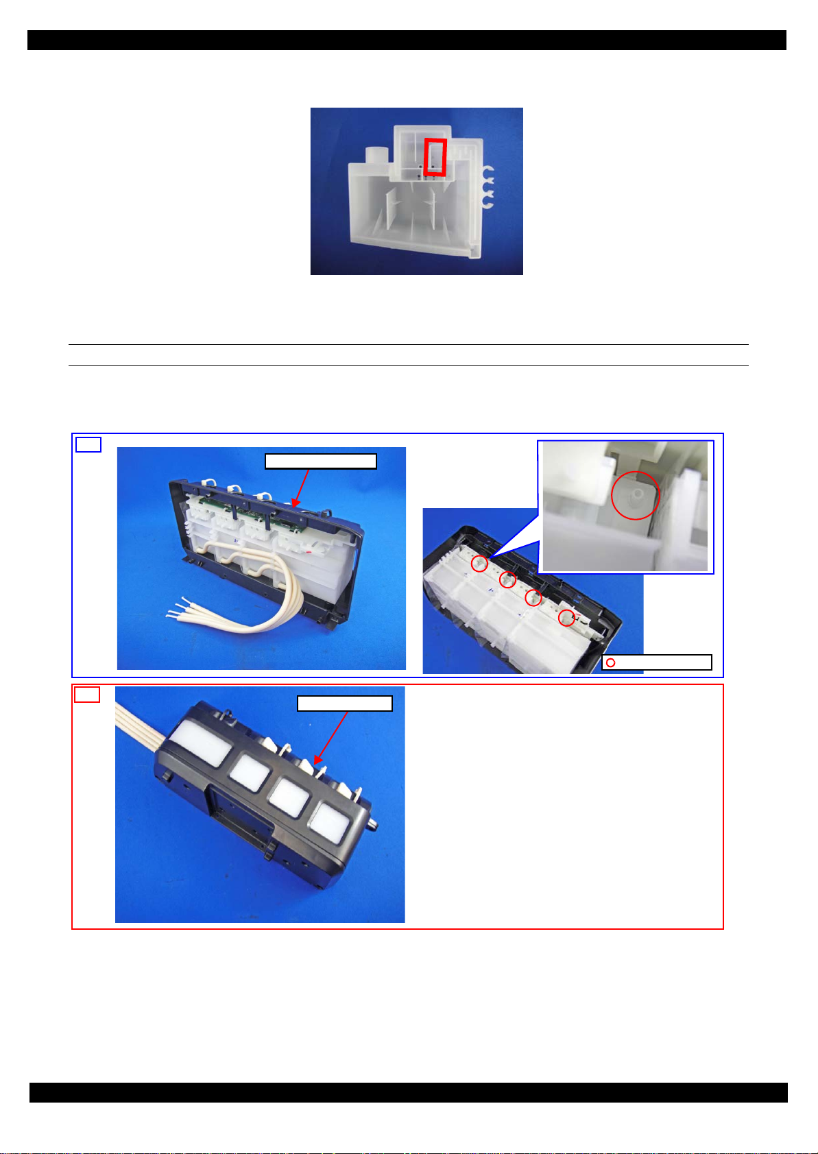
HOW TO PLACE THE INK TANK ASSY WHEN DISASSEMBLING/REASSEMBLING
In order to prevent the ventilation film from getting wet, make sure to place the Ink Supply Tank Assy as below
after removing it.
Figure 2-3. How to Place the Ink Tank Assy
Disassembly/Reassembly Overview 30
Confidential
Page 31

Epson L1455/ET-16500 Revision A
DIFFERENT KINDS OF INK MIXTURE IN THE INK TANK
The different ink could have been mixed due to the ink refilling mistake. If the printing quality issues occur,
maybe it is the ink mixture mistake and refer to the following details.
Different kinds/Different colors ink mixture mean as bellow.
Different kinds: Mix pigment Black ink with dye color ink.
・Head nozzles with ink coagulations.
Different colors: Mix dye color ink with other dye color ink.
・Printing quality issues occur, but it doesn’t have ink coagulation.
Because the power ink flushing uses a lot of ink, the Maintenance Box will be full soon and
SEC recommends that the user’s Maintenance Box is removed.
How to handle the different kinds/different colors ink mixture.
In the case of ink mixture, the head and ink supply unit should be cleaned(Ink tank - Adapter).Both of handling
procedures are shown as below.
Replace CISS system (Ink Tank - Adapter)
1. Replace CISS system.
(See "2.1.4.3 How to remove the CISS system (p34)")
2. Remove the user's Maintenance Box and attach the new Maintenance Box.
3. Fill the CR02 into the ink tank in order to clean the printer head.
4. Execute Power ink flushing in Adjustment Program.
5. After Power ink flushing, confirm Blank printing (printed by CR02). If Blank printing can’t be confirmed,
repeat Power ink flushing.
6. Discharge CR02 in Ink tank and fill the new ink into ink tank.
(See "2.1.4.4 Discharging procedure (p43)")
7. Execute Power ink flushing and confirm print quality.
Disassembly/Reassembly Overview 31
Confidential
Page 32

Epson L1455/ET-16500 Revision A
Joint
Ink Tank
Ink Supply Tube Assy
Ink Adapter Tube
Adapter
2.1.4.2 Factors which Affect the Safety of Service Personnel such as Ink Leakage during
Operation
Ink may spill when removing the following parts from L1455/ET-16500.
This section describes the parts that may cause ink spill and the means to minimize the ink spill when removing
the parts.
If the printer is dirty due to ink leak, please wipe off the dirty with CR2. Make sure not to use
the alcohol and wipe off the ink tube, adapter and ink flushing parts.
THE PARTS THAT MAY CAUSE INK SPILL WHEN REMOVING
Parts When ink may spill
Joint R emoving the Ink Supply Tube Assy / Ink Adapter Tube Assy from the Joint
Ink Tank • Removing the Ink Supply Tube Assy from the Joint
• Removing the Ink Supply Tube from the Ink Tank
Ink Supply
Tube
Adapter Removing the Ink Adapter Tube Assy from the Adapter
Ink Adapter
Tube Assy
Note : These parts are indicated with the icon in disassembly/reassembly flowchart. (See "2.3 Disassembly/Reassembly Procedures
(p46)".)
• Removing the Ink Adapter Tube Assy from the Joint
• Removing the Ink Adapter Tube Assy from the Adapter
Figure 2-4. The parts that may cause ink spill when removing
Disassembly/Reassembly Overview 32
Confidential
Page 33

Epson L1455/ET-16500 Revision A
Carriage
Adapter
Ink path
MEANS DO TO MINIMIZE THE INK SPILL
Before disassembling, confirm that the printer is in the following condition.
Adapter is removed
Before disconnecting the joint parts of the ink path, make sure that the Adapter is removed from the Carriage.
Figure 2-5. Ink spill from Adapter
Disassembly/Reassembly Overview 33
Confidential
Page 34

Epson L1455/ET-16500 Revision A
Decoration Plate
Ink Tube Shield
Screw
Ink Tank Cover
2.1.4.3 How to remove the CISS system
Remove the CISS system as follows.
Necessary tools
・Cloth
・Tube Clip(x4)
・Cotton swab(x4)
・Injector(x4)
・Containers(x4)
How to remove the Ink Tank Assy
1. Remove the screw(x1) that secure the Ink Tube Shield. Sliding it in the arrow direction.
2. Remove the Decoration Plate.(Screw x4))
3. Remove the Ink Tank Cover.
Figure 2-6. Remove the Ink Tank Assy1
Figure 2-7. Remove the Ink Tank Assy2
Disassembly/Reassembly Overview 34
Confidential
Page 35

Epson L1455/ET-16500 Revision A
Screw
Hook
Ink Tank Cover
Holder
・Make sure not to pull the ink tube strongly due to the ink leakage from the
ink tube.
・Confirm that the Tank Cap is fully inserted.
Ink Supply Tube
4. Remove the screws(x3) that secure the Ink Tank Unit(See " Ink Tank Assy (p63)")
5. Release the hooks(x2) on the Ink Tank Assy from frame base.
Figure 2-8. Remove the Ink Tank Assy3
6. Release the Ink Supply Tube from holder of the Ink Supply Tank.
Figure 2-9. Remove the Ink Tank Assy4
Disassembly/Reassembly Overview 35
Confidential
Page 36

Epson L1455/ET-16500 Revision A
Ink End Sensor FFC
Make sure not to pull the ink tube strongly due to the ink leakage from the
ink tube.
Ink End Sensor Lumirror
Screw
・Make sure not to pull the ink tube strongly due to the ink leakage from the
ink tube.
・Confirm that the Tank Cap is fully inserted.
Joint
7. Remove the Ink End Sensor Lumirror and the Ink End Sensor FFC.(See " Ink End Sensor Lumirror (p63)")
Figure 2-10. Remove the Ink Tank Assy5
8. Remove the screw that secu res the Joint while Inclining the Ink Tank as follow.
Figure 2-11. Remove the Ink Tank Assy6
Disassembly/Reassembly Overview 36
Confidential
Page 37

Epson L1455/ET-16500 Revision A
Hook
Make sure not to pull the ink tube strongly due to the ink leakage from the ink tube.
Ink Adapter Tube Assy
Screw
Adapter Cover
Hook
Tube Guide Sheet
Joint (Black)
9. Release the hook on the Ink Adapter Tube Assy and sliding it in the arrow direction.
Figure 2-12. Remove the Ink Tank Assy7
10. Remove the Adapter Cover. (See " Adapter Cover (p62)")
Figure 2-13. Remove the Ink Tank Assy8
11. Release the hooks on the Tube Guide Sheet an d Joint (Black) from Carriage.(See " Ink Adapter Tube Assy (p64)")
Figure 2-14. Remove the Ink Tank Assy9
Disassembly/Reassembly Overview 37
Confidential
Page 38

Epson L1455/ET-16500 Revision A
Make sure not to pull the ink tube strongly due to the ink leakage from the ink tube.
Ink Supply Tube (Yellow)
Ink Supply Tube (Black)
Ink Supply Tube (Magenta)
Ink Supply Tube (Cyan)
12. Remove the Adapter(x4) from Carriage to prevent ink spill from Print Head.(See " Adapter (p64)")
Figure 2-15. Remove the Ink Tank Assy10
13. To minimize ink spill, pinch the Ink Supply Tube (Cyan) with a Tube Clip.
14. Remove the Ink Supply Tube (Cyan) from the Joint with a dry cloth.
Figure 2-16. Remove the Ink Tank Assy11
15. Pinch the Ink Supply Tube (Black) with a Tube Clip.
16. Remove the Ink Supply Tube (Black) from the Joint with a dry cloth.
17. Pinch the Ink Supply Tube (Magenta) with a Tube Clip.
18. Remove the Ink Supply Tube (Magenta) from the Joint with a dry cloth.
19. Pinch the Ink Supply Tube (Yellow) with a Tube Clip.
20. Remove the Ink Supply Tube (Yellow) from the Joint with a dry cloth.
Figure 2-17. Ink Tank Assy
Disassembly/Reassembly Overview 38
Confidential
Page 39

Epson L1455/ET-16500 Revision A
・Make sure not to pull the ink tube strongly due to the ink leakage from the
ink tube.
・Confirm that the Tank Cap is fully inserted.
Remove the Ink Adapter Tube Assy
1. Remove the Ink Tube Shield. (See Figure 2-6(p 34))
2. Remove the Decoration Plate. (See Figure 2-6(p 34))
3. Remove the Ink Tank Cover. (See Figure 2-7(p 34))
4. Remove the screws(x3) that secure the Ink Tank Unit. (See Figure 2-8(p 35))
5. Release the hook on the Ink Tank Assy from frame base. (See Figure 2-8(p 35))
6. Release the Ink Supply Tank Tube from holder of the Ink Supply Tank. (See Figure 2-9(p 35))
7. Inclining the Ink Tank as follow.
Figure 2-18. Remove the Ink Adapter Tube Assy1
8. Execute Power ink flushing in Adjustment Program.
Figure 2-19. Remove the Ink Adapter Tube Assy2
9. Remove the Ink End Sensor Lumirror and the Ink End Sens or FFC.(See Figure 2-10(p 36))
10. Remove the screw(x1) that secure the Joint.(See Figure 2-11(p 36))
11. Release the hook on the Ink Adapter Tube Assy from frame front and sliding it in the arrow direction.(See Figure 2-12(p 37))
12. Remove the Adapter Cover.(See Figure 2-13(p 37))
13. Release the hook on the Tube Guide Sheet and Joint (Black) from Carriage.(See Figure 2-14(p 37))
14. Remove the Adapter(x4) from Carriage to prevent ink spill from Print Head.(See Figure 2-15(p 38))
15. To minimize ink spill, pinch the Ink Supply Tube (Cyan) with a Tube Clip.(See Figure 2-16(p 38))
16. Remove the Ink Supply Tube (Cyan) from the Joint with a dry cloth.(See Figure 2-16(p 38))
17. Pinch the Ink Supply Tube (Black) with a Tube Clip.(See Figure 2-16(p 38))
18. Remove the Ink Supply Tube (Black) from the Joint with a dry cloth.(See Figure 2-16(p 38))
Disassembly/Reassembly Overview 39
Confidential
Page 40

Epson L1455/ET-16500 Revision A
dry cloth
Joint
19. Pinch the Ink Supply Tube (Magenta) with a Tube Clip.(See Figure 2-16(p 38))
20. Remove the Ink Supply Tube (Magenta) from the Joint with a dry cloth.(See Figure 2-16(p 38))
21. Pinch the Ink Supply Tube (Yellow) with a Tube Clip.(See Figure 2-16(p 38))
22. Remove the Ink Supply Tube (Yellow) from the Joint with a dry cloth.(See Figure 2-16(p 38))
23. Remove the joint from the Ink Adapter Tube Assy with a dry cloth.
Figure 2-20. Remove the Ink Adapter Tube Assy3
Disassembly/Reassembly Overview 40
Confidential
Page 41

Epson L1455/ET-16500 Revision A
Before execute Power ink flushing
After execute Power ink flushing
If the ink in the Adapter isn’t discharged completely, discharge ink by using
injector as follows. Be careful, not mix different colors.
Make sure that the Adapter is removed from Carriage, when discharge ink by
using injector.
Injector (x4)
Containers(x4)
Injector (x4)
cotton swab
Ink Adapter Tube Assy
24. Make sure that the ink in the Adapter is discharged.
Figure 2-21. Remove the Ink Adapter Tube Assy4
25. Insert a cotton swab(x4) into the end of the Ink Adapter Tube Assy to prevent ink leaking.
Figure 2-22. Remove the Ink Adapter Tube Assy5
Disassembly/Reassembly Overview 41
Confidential
Page 42

Epson L1455/ET-16500 Revision A
Ink Adapter Tube Assy
26. Slide the Ink Adapter Tube Assy in the arrow direction and remove the Ink Adapte r Tube Assy.
Figure 2-23. Remove the Ink Adapter Tube Assy6
Disassembly/Reassembly Overview 42
Confidential
Page 43

Epson L1455/ET-16500 Revision A
Injector
Container
Refill hole
2.1.4.4 Discharging procedure
Before replace Ink Tank, discharging ink is recommended. Discharge ink as follows.
After all the reassembling work is complete, the discharged ink of each color should be
refilled back to the Ink Supply Tank before performing the adjustment. Confirm the colors
indicated on the film of the Ink Supply Tank so as not to mistake them, and make sure to
refill each ink back to the correct tank from the corresponding ink supply hole.
Necessary tools
″ Containers (x4) for each discharged ink
″ Injector (with a tip of φ3.2mm)
″ Cotton swab (x4)
Discharging procedure
1. Insert the tip of the injector to each of the refill holes on the Ink Supply Tank.
2. Suck out ink in the tanks (x 4) of the Ink Supply Tank and transfer it into the containers (x 4) by color.
Figure 2-24. Discharging Ink
Disassembly/Reassembly Overview 43
Confidential
Page 44

Epson L1455/ET-16500 Revision A
2.
CR Frame
Assy
3.
Printer
Mechanism
ADF/Scanner Unit
2. 2.
3.
2.
4.
2.
2.
2.2 Common cautions when disassembling/reassembling the Product
This section describes common cautions when disassembling/reassembling the product.
Before disassembling/reassembling the printer including this product, be sure to read " Safety Precautions (p3)"
and this section.
Item Content Photo/Illustration
When
handling
parts
1. When handling new parts for replacement, ta ke care n ot to contam inate
or damage them.
2. When disassembling/reassembling the parts, take care not to damage
the FFCs/cables/Ink tube if there is a possibility of coming into cont act
with them.
3. When reassembling the product, take care not to let components of the
unit come off.
When
reassembling
When
applying
When installing parts, take care not to damage them when securing them
by tightening screws.
Do not lubricate any part other than those specified. If grease is applied on
such a part, wipe it off completely. ---
grease
External parts Confirm visually that there are no scratches, dirt, and gaps. --Moving parts After reassembling, confirm that there are no abnormal noises and they
work smoothly.
---
Timing belts 1. Take care not to broke them.
2. Confirm that it is installed properly onto the transmissive sections of
the pinion gear/driven roller.
Motors Take care not to damage them. --Sensors 1. Take care not to touch the detector sections.
2. As for the encoder Sensor used with a circular scale, the photo sensor
section should be set over the encoded area of the circular scale.
3. Take care not to get injured by the sharp ends of the board terminal on
the back of the circuit boards when handling the sensors or the
peripheral parts.
Scales 1. Take care not to touch the encoded area.
2. Install it with the black triangular section up. (CR Scale only)
3. Wipe off alcohol before installing. (CR Scale only)
4. Confirm that they do not touch the photo sensors after installation.
Waste ink
pads
1. Take care not to stain your hands with the waste ink soaked in the ink
pads. If ink comes into contact with your hands, wash it off with water
immediately.
2. Take care not to stain the printer's pa rts with the waste i nk soaked in the
ink pads. If ink comes into contact with the parts, wash it off.
(Especially, pay attention to Paper Guide Front/Lower Porous Pad)
Disassembly/Reassembly Common cautions when disassembling/reassembling the Product 44
Confidential
Page 45

Epson L1455/ET-16500 Revision A
Holder Cam AssyD/E Lever
Protrusion Groove
Ink Supply Tank
A
Housing Upper
2.
Item Content Photo/Illustration
FFCs 1. Be sure to insert them to their connectors on the boards as far as they
will go without any loose connection such as a half-way or slant
connection.
2. Route them along their routing paths.
3. If the double-sided tape that secures the FFCs is not strong enough to
secure them, make sure to replace the tape and secure the FFCs firmly.
Gears When installing gears, pay attention to the following:
• The gear section should not be damaged.
• No foreign material is attached.
• No grease is attached on any parts other than those specified.
PF rollers Do not touch rollers for paper feeding when handling them.
---
---
One Time
parts
ADF/Scanner
Unit
Holder Cam
Assy
After removing One Time parts specified in this manual, do not reuse
them, but be sure to replace them with new ones.
When disassembling/reassembling the ADF/Scanner Unit, make sure to
do the work with the unit open to prevent damage to the Hinges.
Install the assy while aligning the protrusion on the D/E Lever with the
groove on the cam of the Holder Cam Assy.
Ink System 1. Take care not to stain your hands with ink.
2. When you connect the ink tube to another part, insert the ink tube up to
the root of the joint to prevent ink leakage and secure the tube with the
tube clamp.
3. If it's hard t o insert the ink tube to the j oint, appl y CR06 to the inserting
part of the ink tube.
Ink Supply
Tank
When handling the Ink Supply Tank, do not put it with the ventilation hole
(A in the figure on the right) downward. (See
before Disassembling (p29)"
)
One Time icon:
---
"2.1.4 Checks and Precautions
MAC
Address
Label
1. Take care not to stain or damage it.
2. When replacing the Housing Upper, transfer the MAC address label to
the new Housing Upper.
Disassembly/Reassembly Common cautions when disassembling/reassembling the Product 45
Confidential
Page 46

Epson L1455/ET-16500 Revision A
Cassette Assy 1st
Cassette Assy 2nd
Duplex Unit
2.3 Disassembly/Reassembly Procedures
2.3.1 Functional differences between models and component parts
In "2.3.2 Disassembly Flowchart (p48)", the procedures are indicated on the premise that some parts/units are
removed in advance. Make sure to remove the following parts/units before sta r ting disassembly.
Cassette Assy 1st / 2nd
Duplex Unit
Figure 2-25. Removing the Cassette Assy 1st/2nd
Figure 2-26. Removing the Duplex Unit
Disassembly/Reassembly Disassembly/Reassembly Procedures 46
Confidential
Page 47

Epson L1455/ET-16500 Revision A
Maintenance Box
Maintenance Box
Figure 2-27. Rem oving the Maintenance Box
Disassembly/Reassembly Disassembly/Reassembly Procedures 47
Confidential
Page 48

Epson L1455/ET-16500 Revision A
Item Description Reference
Parts/unit name
White-letter
Part/unit supplied as an ASP ---
Black-letter
Part/unit not supplied as an ASP ---
Icon
Indicates a practice or condition that could result in
injury or loss of life if not strictly observed.
Indicates the reference
page in blue-letter
Indicates a practice or condition that could result in
damage to, or destruction of equipment if not strictly
observed.
Indicates the reference
page in blue-letter
Indicates the parts that are inevitably broken in the
disassembling procedure, and should be replaced with a
new one for reassembly.
---
Indicates necessary check items in the disassembling/
assembling procedure.
Indicates the reference
page in blue-letter
Indicates supplementary explanation for disassembly is
given.
Indicates the reference
page in blue-letter
Indicates particular tasks to keep quality of the units are
required.
Indicates the reference
page in blue-letter
Indicates particular routing of cables is required.
Indicates the reference
page in blue-letter
Indicates particular adjustment(s) is/are required.
Chapter 3 " Adjustment
(p71)"
Indicates lubrication is required.
Chapter 4 " Maintenance
(p93)"
Indicates the number of screws securing the parts/units. --Indicates the points secured with other than a screw
such as a hook, rib, dowel or the like.
---
USB Cover
1
4
(p 22) (p 43)
Main Frame Unit
---
---
(p 21) (p 27)
Paper Guide
Upper Assy (p29)
CR Timing Belt
FFC/Cable * 1
Note "*": The boxes with only part names indicates the removal of such parts. If the names of FFCs or cables are
shown, disconnect the FFCs or cables from their connectors.
Black letters indicate a
part/unit not supplied as
an ASP.
The name enclosed in gray
indicate a part/unit that
must be removed on the
way to the target parts.
Shows necessary
procedures before
removing the following
parts.*
Shows the procedure
number on the “FFC/
cable list”.
White letters indicate a
part/unit supplied as
an ASP.
Shows the screw types
and the specified
torque in the “Screw
type/torque list”.
Shows removal/installation
as a unit/assy. is available.
Reference page
2.3.2 Disassembly Flowchart
This section describes procedures for disassembling the parts/units in a flowchart format. For some parts/units,
detailed procedures or precautions are provided (accordingly indicated by icons and cell's color). Refer to the
explanations in the example chart below and perform an appropriate disassembling and assembling procedure.
(See "2.4 Detailed Disassembly/Reassembly Procedure for each Part/Unit (p55)".)
For routing cables, see "2.5 Routing FFCs/cables (p66)".
The example below shows how to see the charts on the following pages.
S2
Disassembly/Reassembly Disassembly/Reassembly Procedures 48
Confidential
Page 49

Epson L1455/ET-16500 Revision A
S20
S18
S2
S18
S19
S20
S20
S5
S2
2.3.2.1 Housing Part
START
USB Cover
(p 58) (p 67)
FFC/Cable* 1
ADF/Scanner
Unit
S7
(p 55)
Hinge Left
S2
---
---
---
Lower Case
2
7
S2
---
6
---
Pickup Holder
1st
(p 58)
---
1
Pickup Roller 1st
---
4
2
(p 53)
(p 58)
---
(p 93)
Pickup Holder
2nd
(p 58)
Pickup Roller 2nd
(p 58)
---
1
---
---
(p 93)
Decoration Plate
S2
---
Duplex Unit
Cover
4
---
S5
(p 71)
2
4
MSF Unit
---
Paper Stopper
Assy 2nd
(p 58)
(p 93)
---
2
2
---
MSF Stopper
Belt
S5
---
ADF Pad Assy
(p 56)
4
4
---
4
Assist Roller
Holder Assy
(p 58)
Document Pad
(p 57)
---
3
---
---
A
ADF Cover Assy
(p 55)
MSF Cover
(p 49)
---
2
A
(p 49)
---
3
---
B
(p 50)
Hinge Right
2
2
FFC/Cable* 2
1
S2
---
---
Ink Tube Shield
Panel Unit
1
---
(p 53)
Ink Tank Assy
(p50)
FFC/Cable* 3
Housing Upper
Assy
(p 66)
Panel Unit (p49)
FFC/Cable* 4
Housing Front
Assy
(p 58) (p 67)
C
(p 51)
2
---
(p 67) (p 71)
Speaker Cover
4
---
3
---
(p 53)
Speaker
---
2
2
4
(p 53)
---
Screw type/torque list
Symbol
S1
FFC/cable list
2
---
---
---
No. FFC/Cable
Disconnect the following FFC and cables from the connectors on the
Main Board, and release their routing.
• ADF motor cable (CN33)
• ADF PE sensor cable (CN71)
• ADF document sensor cable (CN72)
• ADF encoder sensor cable (CN73)
1
• Paper Support Encoder Sensor cable (CN76)
• ADF plunger cable (CN77)
• Scanner Motor cable (CN32)
• Scanner FFC (CN70)
• Scanner Open Sensor cable (CN74)
Disconnect the FFCs/Cables.
• Panel FFC (CN20)
2
• Speaker cable
Disconnect the Panel Grounding Wire (S02).
Disconnect the Duplex Unit Cover Open Sensor cable from the
3
connector (CN60) on the Main Board, and release the routing.
Disconnect the following FFC and cable from the connectors on the
Main Board.
• Panel FFC (CN20)
4
• Cover Open Sensor cable (CN53)
Disconnect the Panel Grounding Wire (S11).
C.B.P-TITE SCREW 2.5x8 F/ZN-3C 4 ± 1kgf・cm
S2
C.B.P-TITE SCREW 3x10 F/ZN-3C 6 ± 1kgf・cm
S3
C.B.P-TITE SCREW 3x10 F/ZN-3C 8
S4
C.B.P-TITE SCREW 3x5 F/ZN-3C 6 ± 1kgf・cm
S5
C.B.P-TITE SCREW 3x8 F/ZN-3C 6
S6
C.B.P-TITE(P4) SCREW 3x8 F/ZN-3C 6 ± 1kgf・cm
S7
C.B.P-TITE(S-P1) SCREW 3x12 F/ZB-3C 6
S8
C.B.P-TITE(S-P1) SCREW 3x12 F/ZN-3C 6 ± 1kgf・cm
S9
C.B.S-TITE SCREW 2.6x6 F/ZN-3C 4
S10
C.B.S-TITE SCREW 3x6 F/ZN-3C 6 ± 1kgf・cm
S11
C.B.S-TITE SCREW 3x6 F/ZN-3C 8
S12
C.B.S-TITE(P4) SCREW 3x10 F/ZN-3C 6 ± 1kgf・cm
S13
C.B.S-TITE(P4) SCREW 3x8 F/ZN-3C 6
S14
C.C SCREW 3x5 F/ZN-3C 8 ± 1kgf・cm
S15
C.P SCREW 3x4 F/ZN-3C 6
S16
C.P-TITE SCREW 2.5x6 F/ZN-3C 3 ± 0.5kgf・cm
S17
C.P-TITE SCREW 3x4 F/ZN-3C 3
C.B.S-TITE SCREW 3x8 F/ZN-3C 6 ± 1kgf・cm
C.B.S-TITE SCREW 3x8 F/ZN-3C 8
C.B.P-TITE SCREW 3x10 F/ZB-3C 6 ± 1kgf・cm
Screw Type Torque
± 1kgf・cm
± 1kgf・cm
± 1kgf・cm
± 1kgf・cm
± 1kgf・cm
± 1kgf・cm
± 1kgf・cm
± 0.5kgf・cm
± 1kgf・cm
Flowchart 2-1. Disassembly Flowchart of Housing Part (1)
Disassembly/Reassembly 49
Confidential
Page 50

Epson L1455/ET-16500 Revision A
S18
S19
S20
S21
S18
S10
S2
S18
S21
2.3.2.2 CISS System/Print Head Part
B
Ink Tank Cover
---
Ink End Sensor
Lumirror
(p 63)
Ink Tube Shield
(p49)
(p 49)
---
2
---
2
Tank Cap
(p 64)
Head FFC
Printhead
(p 60)
S1
(p 71)
---
---
(p 50)
5
(p 50)
6
CIS FFC
Adapter Cover
(p 62)
Holder Board
Ink Tank Hous-
ing Lower
1
3
(p 64)
2
2
Tank Cap (p50)
Ink Adapter
Tube (Black1)
---
Ink Adapter
Tube (Black2)
---
---
---
---
1
Ink Adapter
Tube (Color1)
---
---
1
---
2
3
(p 65)
Ink Tank Hous-
ing Upper
2
2
S2
(p 65)
2
Ink Adapter
Tube (Color2)
---
Tube Clamp (x4)
(p 63)
Joint (Black)
---
---
---
---
1
Tube Guide
---
4
---
---
4
Joint (Color)
---
Tube Guide
Cover
---
---
---
---
2
Ink End Sensor FFC
Ink Tank Assy
(p 34) (p 63)
Joint
(p 65)
Adapter Cover
(p50)
Ink Adapter
Tube Assy
(p 64)
---
---
Ink Tank
Pourous Pad
---
3
2
---
---
5
(p 50)
1
Ink Tank (Black)
---
---
(p 65)
Ink End Sensor
Board
(p 65)
Ink End Sensor
Board Holder
(p 65)
Ink Tank
(Color)x4
(p 65)
---
4
4
8
Ink Supply Tube
---
---
(p 65)
---
4
Screw type/torque list
Symbol
S1
C.B.P-TITE SCREW 2.5x8 F/ZN-3C 4 ± 1kgf・cm
S2
C.B.P-TITE SCREW 3x10 F/ZN-3C 6 ± 1kgf・cm
S3
C.B.P-TITE SCREW 3x10 F/ZN-3C 8
S4
C.B.P-TITE SCREW 3x5 F/ZN-3C 6 ± 1kgf・cm
S5
C.B.P-TITE SCREW 3x8 F/ZN-3C 6
S6
C.B.P-TITE(P4) SCREW 3x8 F/ZN-3C 6 ± 1kgf・cm
S7
C.B.P-TITE(S-P1) SCREW 3x12 F/ZB-3C 6
S8
C.B.P-TITE(S-P1) SCREW 3x12 F/ZN-3C 6 ± 1kgf・cm
S9
C.B.S-TITE SCREW 2.6x6 F/ZN-3C 4
S10
C.B.S-TITE SCREW 3x6 F/ZN-3C 6 ± 1kgf・cm
S11
C.B.S-TITE SCREW 3x6 F/ZN-3C 8
S12
C.B.S-TITE(P4) SCREW 3x10 F/ZN-3C 6 ± 1kgf・cm
S13
C.B.S-TITE(P4) SCREW 3x8 F/ZN-3C 6
S14
C.C SCREW 3x5 F/ZN-3C 8 ± 1kgf・cm
S15
C.P SCREW 3x4 F/ZN-3C 6
S16
C.P-TITE SCREW 2.5x6 F/ZN-3C 3 ± 0.5kgf・cm
S17
C.P-TITE SCREW 3x4 F/ZN-3C 3
Screw Type Torque
± 1kgf・cm
± 1kgf・cm
± 1kgf・cm
± 1kgf・cm
± 1kgf・cm
± 1kgf・cm
± 1kgf・cm
± 0.5kgf・cm
C.B.S-TITE SCREW 3x8 F/ZN-3C 6 ± 1kgf・cm
Adapter (Black)
Adapter (Color)
1
---
---
---
---
Tube Guide
Sheet
---
---
6
(p 50)
C.B.S-TITE SCREW 3x8 F/ZN-3C 8
C.B.P-TITE SCREW 3x10 F/ZB-3C 6 ± 1kgf・cm
C.B.P-TITE SCREW 2.5x8 F/ZN-3C 3
C.B.P-TITE SCREW 2.5x8 F/ZN-3C
± 1kgf・cm
± 0.5kgf・cm
(p 64)
(p 64)
(p 63)
Flowchart 2-2. Disassembly Flowchart of Housing Part (2)
Disassembly/Reassembly 50
Confidential
Page 51

Epson L1455/ET-16500 Revision A
S10
S2
S3
S2
S9
S11
S12
S12
S3
S2
S11
S18
S19
S20
2.3.2.3 Printer Mechanism Part
(p 49)
C
FFC/Cable* 5
Main Board Unit
S11
(p 59) (p 68)
(p 71)
CR Scale (p52)
CR Driven
Pulley Assy (p52)
Head FFC
CR Guide Frame
Assy
(w/CR Unit)
S13
(p 61)
(p 69) (p 71) (p 93)
Stacker Assy
FAX FFC
---
FAX Unit
Ink tube
Clamp Tube
---
6
---
---
7
(p 67)
(p 54)
2
---
8
---
(p 54)
---
1
FFC/Cable* 6
Power Supply
Unit
(p 71)
D
(p 52)
2
---
Ink system Assy
2
S2
PF Encoder FFC
PF Encoder
Sensor
6
4
(p 62)
2
---
(p 59) (p 93)
Gear Cover
(p 60) (p 93)
---
---
Lower Case
(p49)
3
Pickup Assy 1st
1
1
Front Frame
S11
(p 61) (p 71) (p 93)
Star Wheel Assy
S11
(p 61) (p 69)
(p 71)
Clamp Tube
(p51)
Ink system Assy
(p51)
Relay Board
FFC Guide (p52)
E
(p 52)
(p 59) (p 93)
CR Scale Sup-
port Plate
4
1
---
PG Adjustment
Cam Left
1
---
1
2
3
---
1
F
(p 52)
PG Adjustment
Cam Right
---
1
1
FFC/cable list
No. FFC/Cable
Disconnect all the FFCs and cables connected to the Main Board.
• Disconnect the FAX FFC from FAX Unit.
5
• Grounding Wire(S10)
Disconnect the Power Supply Unit cable from the connector (CN501) on
6
the Main Board, and release the routing.
Flowchart 2-3. Disassembly Flowchart of Printer Mechanism Part (1)
Screw type/torque list
Symbol
S1
C.B.P-TITE SCREW 2.5x8 F/ZN-3C 4 ± 1kgf・cm
S2
C.B.P-TITE SCREW 3x10 F/ZN-3C 6 ± 1kgf・cm
S3
C.B.P-TITE SCREW 3x10 F/ZN-3C 8
S4
C.B.P-TITE SCREW 3x5 F/ZN-3C 6 ± 1kgf・cm
S5
C.B.P-TITE SCREW 3x8 F/ZN-3C 6
S6
C.B.P-TITE(P4) SCREW 3x8 F/ZN-3C 6 ± 1kgf・cm
S7
C.B.P-TITE(S-P1) SCREW 3x12 F/ZB-3C 6
S8
C.B.P-TITE(S-P1) SCREW 3x12 F/ZN-3C 6 ± 1kgf・cm
S9
C.B.S-TITE SCREW 2.6x6 F/ZN-3C 4
S10
C.B.S-TITE SCREW 3x6 F/ZN-3C 6 ± 1kgf・cm
S11
C.B.S-TITE SCREW 3x6 F/ZN-3C 8
S12
C.B.S-TITE(P4) SCREW 3x10 F/ZN-3C 6 ± 1kgf・cm
S13
C.B.S-TITE(P4) SCREW 3x8 F/ZN-3C 6
S14
C.C SCREW 3x5 F/ZN-3C 8 ± 1kgf・cm
S15
C.P SCREW 3x4 F/ZN-3C 6
S16
C.P-TITE SCREW 2.5x6 F/ZN-3C 3 ± 0.5kgf・cm
S17
C.P-TITE SCREW 3x4 F/ZN-3C 3
C.B.S-TITE SCREW 3x8 F/ZN-3C 6 ± 1kgf・cm
C.B.S-TITE SCREW 3x8 F/ZN-3C 8
C.B.P-TITE SCREW 3x10 F/ZB-3C 6 ± 1kgf・cm
Screw Type Torque
± 1kgf・cm
± 1kgf・cm
± 1kgf・cm
± 1kgf・cm
± 1kgf・cm
± 1kgf・cm
± 1kgf・cm
± 0.5kgf・cm
± 1kgf・cm
Disassembly/Reassembly 51
Confidential
Page 52

Epson L1455/ET-16500 Revision A
S11
S2
S11
S18
S19
S20
E
Gear Cover
(p51)
One Way Clutch
Gear
---
APG Unit
Support Plate
(p52)
FFC/Cable* 8
Main Frame
Unit
S11
S6
(p 62)
(p 70) (p 71) (p 93)
Paper Guide
Lower Porous
Pad
(p 71)
(p 51)
---
---
---
---
---
(p 51)
F
FFC/Cable* 7
D
(p 51)
Torsion Spring
Waste Ink Tray
Cover (p52)
Relay Board
Assy (p52)
CR Driven
Pulley Assy (p52)
Relay Board
FFC Guide
(p 68)
APG Unit Sup-
port Plate
---
2
---
1
---
CR Scale
---
2
(p 60)
FFC/Cable* 9
Ink tube
Frame Base 2nd
(p 62)
Assy
S2
(p 69) (p 71)
7
---
11
(p 54)
Waste Ink Tray
Cover
S2
(p 68)
Holder Cam
Assy
2
---
S11
(p 60)
1
1
Relay Board FFC
Paper Stopper
Assy 1st
2
S18
8
(p 58) (p 93)
---
10
(p 54)
Relay Board
Assy
(p 68)
Waste Ink Tray
Holder
---
1
9
(p 54)
3
APG Unit
S2
---
---
APG Driven
Shaft Support
Plate (p52)
CR Scale (p52)
CR Driven
Pulley Assy (p52)
APG Driven
Shaft
---
---
(p 60)
Torsion Spring 241.9 (x6)
Extension Spring 0.99 (x2)
Paper Guide
Upper Assy
---
10
(p 61)
(p 71)
Extension Spring
CR Driven Pul-
ley Assy
(p 71) (p 93)
---
4
2
S2
(p 71)
---
FFC/cable list
No. FFC/Cable
Release the following FFC and cable from the Relay Board FFC Guide.
7
• Relay Board FFC
• CR Motor cable
Release the routing of following FFC and cables.
• Relay Board FFC
• CR Motor cable
8
• PE Sensor cable
• PF Motor cable
Release the routing of following FFC and cables.
• ASF Motor cable
9
• ASF Encoder FFC
• Frame Base 2nd Assy Paper Stopper sensor cable
APG Driven
Shaft Support
Plate
5
---
---
Screw type/torque list
Symbol
S1
C.B.P-TITE SCREW 2.5x8 F/ZN-3C 4 ± 1kgf・cm
S2
C.B.P-TITE SCREW 3x10 F/ZN-3C 6 ± 1kgf・cm
S3
C.B.P-TITE SCREW 3x10 F/ZN-3C 8
S4
C.B.P-TITE SCREW 3x5 F/ZN-3C 6 ± 1kgf・cm
S5
C.B.P-TITE SCREW 3x8 F/ZN-3C 6
S6
C.B.P-TITE(P4) SCREW 3x8 F/ZN-3C 6 ± 1kgf・cm
S7
C.B.P-TITE(S-P1) SCREW 3x12 F/ZB-3C 6
S8
C.B.P-TITE(S-P1) SCREW 3x12 F/ZN-3C 6 ± 1kgf・cm
S9
C.B.S-TITE SCREW 2.6x6 F/ZN-3C 4
S10
C.B.S-TITE SCREW 3x6 F/ZN-3C 6 ± 1kgf・cm
S11
C.B.S-TITE SCREW 3x6 F/ZN-3C 8
S12
C.B.S-TITE(P4) SCREW 3x10 F/ZN-3C 6 ± 1kgf・cm
S13
C.B.S-TITE(P4) SCREW 3x8 F/ZN-3C 6
S14
C.C SCREW 3x5 F/ZN-3C 8 ± 1kgf・m
S15
C.P SCREW 3x4 F/ZN-3C 6
S16
C.P-TITE SCREW 2.5x6 F/ZN-3C 3 ± 0.5kgf・cm
S17
C.P-TITE SCREW 3x4 F/ZN-3C 3
C.B.S-TITE SCREW 3x8 F/ZN-3C 6 ± 1kgf・cm
C.B.S-TITE SCREW 3x8 F/ZN-3C 8
C.B.P-TITE SCREW 3x10 F/ZB-3C 6 ± 1kgf・cm
Screw Type Torque
± 1kgf・cm
± 1kgf・cm
± 1kgf・cm
± 1kgf・cm
± 1kgf・cm
± 1kgf・cm
± 1kgf・cm
± 0.5kgf・cm
± 1kgf・cm
Flowchart 2-4. Disassembly Flowchart of Printer Mechanism Part (2)
Disassembly/Reassembly 52
Confidential
Page 53

Epson L1455/ET-16500 Revision A
S2
S2
S5
S2
S18
S19
S20
1
LD Shaft
(p 93)
Extension Spring
ADF LD Assy
(p 55)
3
Duplex Unit
Cover Open
Sensor Assy
---
Hinge Right
(p49)
Housing Upper
---
(p 49)
(p 71)
(p 49)
(p 49)
2
(p 49)
4
FFC/Cable* 10
FFC/Cable* 15
---
ADF Unit
1
---
3
(p 71)
ADF Decoration
Plate Front
(p 55)
---
2
ADF Decoration
Plate Rear
(p 55)
ADF Cover
Right
---
2
(p 56)
---
8
---
2
1
1
ADF Decoration
Plate Rear (p53)
ADF Cover
Right (p53)
ADF Cover Assy
(p49)
ADF Cover
Front
(p 56)
ADF Cover
Rear (p53)
ADF Paper
Support Cover
(p53)
Paper Support
Encoder Sensor
(p53)
ADF Paper
Support Assy
(p53)
FFC/Cable* 13
ADF Cover Rear
3
5
(p 56)
3
10
ADF Paper
Support Cover
S5
(p 57)
2
---
FFC/Cable* 11
Paper Support
Encoder Sensor
1
S5
(p 57)
---
FFC/Cable* 12
---
---
ADF Motor Unit
(p 66) (p 71)
ADF Paper
Support Assy
4
---
(p 57) (p 66)
---
4
ADF Frame Base
---
---
---
Scanner Unit
---
Grounding Wire
3
(p 71) (p 93)
Scanner FFC
Cover
---
Scanner Housing
Upper Assy
Scanner FFC
CIS Module
2
(p 57) (p 66)
(p 57) (p 66)
FFC/cable list
No. FFC/Cable
Pull out the cables of ADF Unit from the hole on the
10
Scanner Unit.
11 Disconnect the Paper Support Encoder Sensor cable.
Release the routing of the Paper Support Encoder Sensor
12
cable.
Release the routing of the following cables.
13
14
15 Release the routing of the Cover Open Sensor cable.
• Paper Support Encoder Sensor cable
• ADF plunger cable
Disconnect the Grounding Wire
Release the routing of the Scanner Motor Assy cable.
S2
(p 57)
10
5
E-ring
Combination Gear25.2.9.0553
Combination Gear21.6.10.8
Spacer
Scanner Rail Strengthen
Plate Grounding Spring
---
2
FFC/Cable* 14
Scanner Motor
(p 66)
Screw type/torque list
Symbol
S1
C.B.P-TITE SCREW 2.5x8 F/ZN-3C 4 ± 1kgf・cm
S2
C.B.P-TITE SCREW 3x10 F/ZN-3C 6 ± 1kgf・cm
S3
C.B.P-TITE SCREW 3x10 F/ZN-3C 8
S4
C.B.P-TITE SCREW 3x5 F/ZN-3C 6 ± 1kgf・cm
S5
C.B.P-TITE SCREW 3x8 F/ZN-3C 6
S6
C.B.P-TITE(P4) SCREW 3x8 F/ZN-3C 6 ± 1kgf・cm
S7
C.B.P-TITE(S-P1) SCREW 3x12 F/ZB-3C 6
S8
C.B.P-TITE(S-P1) SCREW 3x12 F/ZN-3C 6 ± 1kgf・cm
S9
C.B.S-TITE SCREW 2.6x6 F/ZN-3C 4
S10
C.B.S-TITE SCREW 3x6 F/ZN-3C 6 ± 1kgf・cm
S11
C.B.S-TITE SCREW 3x6 F/ZN-3C 8
S12
C.B.S-TITE(P4) SCREW 3x10 F/ZN-3C 6 ± 1kgf・cm
S13
C.B.S-TITE(P4) SCREW 3x8 F/ZN-3C 6
S14
C.C SCREW 3x5 F/ZN-3C 8 ± 1kgf・cm
S15
C.P SCREW 3x4 F/ZN-3C 6
S16
C.P-TITE SCREW 2.5x6 F/ZN-3C 3 ± 0.5kgf・cm
S17
C.P-TITE SCREW 3x4 F/ZN-3C 3
C.B.S-TITE SCREW 3x8 F/ZN-3C 6 ± 1kgf・cm
C.B.S-TITE SCREW 3x8 F/ZN-3C 8
C.B.P-TITE SCREW 3x10 F/ZB-3C 6 ± 1kgf・cm
Assy
S8
(p 66) (p 71)
Cover Open
Sensor
(p 67)
Speaker Cover
(p49)
Speaker (p49)
Grounding Wire
Panel FFC
Ferrite core (x3)
Housing Front
2
---
---
Screw Type Torque
± 1kgf・cm
± 1kgf・cm
± 1kg・cm
± 1kgf・cm
± 1kgf・cm
± 1kgf・cm
± 1kgf・cm
± 0.5kgf・cm
± 1kgf・cm
---
---
---
---
Flowchart 2-5. Disassembly Flowchart of Printer Mechanism Part (3)
Disassembly/Reassembly 53
Confidential
Page 54

Epson L1455/ET-16500 Revision A
S10
S16
S14
S15
S18
S19
S20
10
Extension Spring
PF Timing Belt
PF Motor
(p 62) (p 69)
(p 71)
(p 52)
(p 51)
7
Cable Support
Plate
S3
---
---
Wireless LAN Module
cable(CN9)
FAX Shield Plate
/FAX Connector
1
Wireless LAN
Module
S11
---
2
---
Shield Plate
Upper
(w/Wireless LAN
Module)
S11
(p 60)
4
2
FAX Board
8
Cover
S3
---
S19
(p 51)
---
(p 52)
9
Relay Board
CSIC Terminal
3
---
2
---
Relay Board
(p54)
Relay Board
---
2
---
---
Main Board
4
---
Acetate Tape
Grounding Wire(S10)
FFC/Cable* 16
---
---
CR Motor cable
CR Motor
APG Driven
Shaft Support
Plate (p52)
APG Driven
Shaft (p52)
S17
(p 71)
Shield Plate
Lower (w/Cable
Support Plate)
---
Paper Guide
2
---
(p 70) (p 71)
2
---
Upper Assy (p52)
PE Lever Assy
---
11
ASF Motor Assy
S2
---
Spur Gear 16
1
S4
(p 71)
Paper Guide
Middle
---
---
Lower Case
(p49)
---
(p 52)
2
---
Screw type/torque list
---
---
---
(p 93)
PE sensor cable
2
Pickup Assy 2nd
S2
(p 59) (p 93)
1
1
PE Sensor
FFC/cable list
---
2
(p 70) (p 71)
No. FFC/Cable
Release the routing of the following FFC and cable.
16
• ASF Motor cable
• ASF Motor Encoder FFC
Symbol
S1
S2
S3
S4
S5
S6
S7
S8
S9
S10
S11
S12
S13
S14
S15
S16
S17
Relay Board
Holder
---
---
---
Screw Type Torque
C.B.P-TITE SCREW 2.5x8 F/ZN-3C 4 ± 1kgf・cm
C.B.P-TITE SCREW 3x10 F/ZN-3C 6 ± 1kgf・cm
C.B.P-TITE SCREW 3x10 F/ZN-3C 8
C.B.P-TITE SCREW 3x5 F/ZN-3C 6 ± 1kgf・cm
C.B.P-TITE SCREW 3x8 F/ZN-3C 6
C.B.P-TITE(P4) SCREW 3x8 F/ZN-3C 6 ± 1kgf・cm
C.B.P-TITE(S-P1) SCREW 3x12 F/ZB-3C 6
C.B.P-TITE(S-P1) SCREW 3x12 F/ZN-3C 6 ± 1kgf・cm
C.B.S-TITE SCREW 2.6x6 F/ZN-3C 4
C.B.S-TITE SCREW 3x6 F/ZN-3C 6 ± 1kgf・cm
C.B.S-TITE SCREW 3x6 F/ZN-3C 8
C.B.S-TITE(P4) SCREW 3x10 F/ZN-3C 6 ± 1kgf・cm
C.B.S-TITE(P4) SCREW 3x8 F/ZN-3C 6
C.C SCREW 3x5 F/ZN-3C 8 ± 1kgf・cm
C.P SCREW 3x4 F/ZN-3C 6
C.P-TITE SCREW 2.5x6 F/ZN-3C 3 ± 0.5kgf・cm
C.P-TITE SCREW 3x4 F/ZN-3C 3
C.B.S-TITE SCREW 3x8 F/ZN-3C 6 ± 1kgf・cm
C.B.S-TITE SCREW 3x8 F/ZN-3C 8
C.B.P-TITE SCREW 3x10 F/ZB-3C 6 ± 1kgf・cm
± 1kgf・cm
± 1kgf・cm
± 1kgf・cm
± 1kgf・cm
± 1kgf・cm
± 1kgf・cm
± 1kgf・cm
± 0.5kgf・cm
± 1kgf・cm
Flowchart 2-6. Disassembly Flowchart of Printer Mechanism Part (4)
Disassembly/Reassembly 54
Confidential
Page 55

Epson L1455/ET-16500 Revision A
ADF Unit
Scanner Unit
Hook
Bottom of ADF/Scanner Unit
Check point
ADF hinge spacer
ADF hinge
ADF hinge spacers
ADF hinges
ADF hinge spacer
Check point
ADF hinge
Hook
ADF Decoration Plate Front
Rib
ADF Decoration
Plate Front
ADF Decoration Plate Rear
ADF Decoration
Plate Rear
Hook
Rib
ADF LD Assy
Extension Spring 0.99 ADF Cover Assy
LD Shaft edge
LD Shaft
Shaft of ADF LD Assy
Left
Lock Release Shaft
Cover Lock
Release Link
Cover Lock
Release
Middle Link
Right
Lock Release Shaft
Cover Lock Release Rear Link
ADF LD Assy
2.4 Detailed Disassembly/Reassembly Procedure for each Part/Unit
ADF Decoration Plate Front/Rear
ADF Unit/Scanner Unit
When removing the ADF Decoration Plate Front/Rear, release the hooks and ribs beforehand.
ADF LD Assy
Inside of ADF Cover Assy
The ADF hinge spacers are inserted to the hooks on the ADF hinges to prevent the ADF Unit from disengaging from the Scan ner Unit by the shocks
caused when the ADF Unit is opened or closed. When the ADF hinge spacers are set in their regular positions, the hooks on the ADF hinges cannot
be released; however, by turning the ADF/Scanner Unit upside down, the ADF hinge spacers move from the regular positions, and then the hooks on
the ADF hinges can be released.
When removing the ADF Unit/Scanner Unit, place it with its bottom up and release the hooks (x3) shown above in advance.
When installing the ADF Unit/Scanner Unit, make sure that the ADF hinge spacers (x2) are inserted at the hooks (x2) on the ADF hinges.
Disassembly/Reassembly Detailed Disassembly/Reassembly Procedure for each Part/Unit 55
Attach the extension spring 0.99 as shown above.
After installing the ADF LD Assy to the ADF Cover Assy,
install the LD shaft while aligning the shape of its end wit h that
of the shaft of the ADF LD Assy.
If the Cover Lock Release Link, the Cover Lock Release Middle
Link or the Cover Lock Release Rear Link comes off when
removing the ADF LD Assy, attach it back as shown above.
Confidential
Page 56

Epson L1455/ET-16500 Revision A
Bottom
ADF Cover Right
Hook
Dowel
2
7
10
3
4
5
8
9
1
6
Front
At Dowel
Release the hooks (x9) and the dowel in the order shown above, then remove the ADF Cover Rear.
Rear of ADF Cover Right
ADF Cover Assy
ADF Cover Right
ADF Cover Right ADF Unit
ADF Cover Rear
ADF Cover Rear
ADF Cover Assy
2
3
4
Bottom
ADF Pad Assy
1
Center hook
Front
Rear of ADF Cover Front
Center hook
5
Release the hooks (x5) in the order shown above, then remove the ADF Cover Front.
Hook
Dowel
ADF Unit
ADF Cover Front
ADF Unit (1)
ADF Unit (2)
The figures above indicate the hooks and dowels that secure the parts and units.
Disassembly/Reassembly Detailed Disassembly/Reassembly Procedure for each Part/Unit 56
The figures above indicate the hooks and dowels that secure the parts and units.
Confidential
Page 57

Epson L1455/ET-16500 Revision A
C.B.P-TITE SCREW 3x8 F/ZN-3C (6±1 kgf·cm)
ADF Paper Support Assy
Dowel
Shaft
ADF Paper Support Cover
Paper Support Encoder Sensor cable
Paper Support Encoder Sensor
Standard line
ADF Unit
20 mm
20 mm
262 mm
26 mm
147.5 mm147.5 mm
168.5 mm 127 mm30 mm 30 mm
30 mm30 mm
75 mm
438.5 mm
75 mm
Sponge positions on back of Document Pad
Document Pad
Scanner Housing Lower
Bottom of Scanner Unit
1
2
34
6
5
7
C.B.P-TITE SCREW 3x10 F/ZB-3C (6±1 kgf
·cm)
Scanner Housing Upper Assy
9 8 10
C.B.P-TITE SCREW 3x10 F/ZN-3C (6±1 kgf
·cm)
Upper of Scanner Unit
Scanner Carriage
Torsion Spring 43.6
Scanner Timing Belt
Protrusion
Attach to CIS module
side inner than this
projection.
Back of Scanner Carriage
CIS Module
Spring
Foot 1
Section A
Scanner Rail Strengthen
Plate Grounding Spring
Spring Foot 2
Scanner Motor
Scanner Rail Strengthen Plate
Dowel of Scanner Housing Lower
Scanner grounding wire
Cutout
Scanner Motor Plate
C.B.P-TITE(S-P1) SCREW 3x12 F/ZN-3C (6±1 kgf·cm)
1
2
Hole
Scanner FFC Cover
Scanner Housing Lower
Hook A
Scanner FFC Cover
Hook B
Install with the hook
A in this way.
2
1
Bottom of Scanner Unit
ADF Paper Support Cover/Paper Support Encoder Sensor/ADF Paper Support Assy
On the ADF Paper Support Assy, the Paper Support Encoder Sensor for paper width detection is mounted. Because the ADF Paper Support Assy is
connected with the ADF unit by the Paper Support Encoder Sensor cable, release the routing of the cable following the disassembly procedure below.
Remove the ADF Paper Support Cover/Paper Support Encoder Sensor/ADF Paper Support Assy as follows.
1. Release the dowels (x2) and shafts (x2) on the ADF Paper Support Assy, and turn the assy upside down.
2. Remove the screws (x2) that secure the ADF Paper Support Cover, and remove the ADF Paper Support Cover.
3. Remove the screw that secures th e Paper Support Encoder Sensor, and disconnect the Paper Support Encoder Sensor cable from the connector on
the Paper Support Encoder Sensor, then remove the sensor.
4. Release the routing of the Paper Support Encoder Sensor cable, then remove the ADF Paper Support Assy.
Document Pad
Attach double-sided tape on the pieces of sponge on the Document Pad indicated in green in the figure above, and attach the Document Pad to the
ADF Unit.
After attaching the Document Pad, make sure the Document Pad is attached within the standard line shown above and the sponge pieces are not
sticking out from the Document Pad.
Scanner Housing Upper Assy
Tighten the screws in the order indicated in the figure above.
Disassembly/Reassembly Detailed Disassembly/Reassembly Procedure for each Part/Unit 57
If the Torsion Spring 43.6 has come off from the Scanner Timing
Belt, attach it to the CIS module side inner than this projection on
the Scanner Carriage.
Scanner Carriage
Scanner Motor Assy
Tighten the screws in the order indicated in the figure above.
Secure the scanner grounding wire and the Scanner Motor Assy
together with the screw 2 shown above.
When attaching the Scanner Rail Strengthen Plate Grounding
Spring, follow the procedure below.
1. Insert the spring leg 1 of the Scanner Rail Strengthen Plate
Grounding Spring into the hole of the Scanner Rail Strengthen
Plate.
2. Attach the section A of the Scanner Rail Strengthen Plate
Grounding Spring to the dowel of the Scanner Housing Lower.
3. Attach the spring leg 2 of the Scanne r R ail Strengthen Plate
Grounding Spring to the cutout of the Scanner Motor Plate.
Scanner FFC Cover
When installing the Scanner FFC Cover, install it with the hook A
of the cover to the rear of the printer, and secure the cover to the
Scanner Housing Lower in the order of hook B and hook A.
Confidential
Page 58

Epson L1455/ET-16500 Revision A
Hook
C.B.P-TITE SCREW 3X10 F/ZN-3C (6±1 kgf·cm)
USB Cover
Paper Stopper
Compression
Spring 0.9
Compression
Spring 0.787
Secure springs (x4) with dowels.
Slider Base
Cam Slider
Slider Cassette
C.B.S-TITE SCREW 3x8 F/ZN-3C (6±1kgf·cm)
1 2
Paper Stopper Assy 1st
1
2
Paper Stopper Assy 2nd
C.B.S-TITE SCREW 3x8 F/ZN-3C (6±1kgf·cm)
Assist Roller Holder Assy
Hook
Dowel
Assist Roller Holder Assy
Assist Roller
Upper
Housing Front Assy
Upper
Housing Front Assy
Housing Front Assy
Hook
C.B.P-TITE SCREW 3x10 F/ZN-3C (6±kgf·cm)
Left
Housing Front Assy
Stacker Assy
Right
Housing Front Assy
Hook
Pickup Holder 1st/
Pickup Roller 1st
Pickup Holder 1st
To 0 digit To 130 digit
Rubber portions
Pickup Roller 1st
Hook
Pickup Holder 2nd/
Pickup Roller 2nd
Pickup Holder 2nd
To 0 digitTo 130 digit
Rubber portions
Pickup Roller 2nd
USB Cover
Paper Stopper Assy 1st/2nd (1)
Paper Stopper Assy 1st/2nd (2)
Assist Roller Holder Assy
Be careful not to damage the hooks (x7) that secure the USB
Cover.
When removing the USB Cover, remove the screws (x2) shown
above and slide the cover in the direction of the arrow to remove it.
Housing Front Assy
If any of the parts of the Paper Stopper Assy 1st/2nd comes off
when removing it, be sure to reassemble the Paper Stopper Assy
1st/2nd as shown above.
Tighten the screws in the order indicated in the figure above.
Pickup Holder 1st/2nd, Pickup Roller 1st/2nd
When removing the Assist Roller Holder Assy, remove the Assist
Roller and then release the hook and dowels (x2) beforehand.
Disassembly/Reassembly Detailed Disassembly/Reassembly Procedure for each Part/Unit 58
Remove the Housing Front Assy as follows.
1. Pull out the Stacker Assy taking care not to let it interfere with the Housing Front Assy.
2. Remove the screws (x2) that secure the Housing Front Assy.
3. Release the hooks (x2) on the Housing Front Assy, then remove the Housing Front Assy.
Be careful not to touch the rubber potions on the Pickup Roller 1st/2nd with bare hands.
When removing the Pickup Roller 1st, take care not to drop or lose the parts because its removal should be done in a very narrow space.
When removing the Pickup Holder 1st/2nd, make sure to release the hooks shown above beforehand.
When installing the Pickup Roller 1st/2nd, install the roller shafts on them in the order of the shaft on the 130-digit side and the one on the 0 digit
side.
When installing the Pickup Holder 1st/2nd, make sure the attachment directions of the holders are correct.
Confidential
Page 59

Epson L1455/ET-16500 Revision A
Upper
Main Board Unit
C.B.S-TITE SCREW 3x6 F/ZN-3C (8±1 kgf·cm)
FAX Unit
C.B.P-TITE SCREW 3x10 F/ZN-3C (6±1 kgf·cm)
C.B.P-TITE SCREW 3x10 F/ZN-3C (8±1 kgf·cm)
Rear
Clamp Tube
Rib
Waste Ink Tube
Ink system Assy
Dowel
Hole
Frame Base 1st Assy
Frame Base 1st Assy
Ink system Assy
Waste Ink Tray Cover
Waste Ink Tube
Maintenance
Box Waste
Ink Joint
Clamp Tube
Cap Slider
C.B.P-TITE SCREW 3x10 F/ZN-3C (6±1 kgf·cm)
Slide the Cap Slider in the direction of the arrow, then secure the
Ink System with a screw.
Waste Ink Tray Cover
Pickup Driven ShaftPickup Escape Lever
Pickup Assy 1st
The location where
the Pickup Escape
Lever interferes.
Bottom
Pickup Assy 1st
Spur Gear 32
Hook
Upper
C.B.P-TITE SCREW 3x10 F/ZN-3C (6±1 kgf·cm)
C.B.P-TITE SCREW 3x10 F/ZN-3C (6±1 kgf·cm)
Pickup Escape LeverPickup Driven Shaft
The location where
the Pickup Escape
Lever interferes.
Spur Gear 16
Upper
Pickup Assy 2nd
Pickup Assy 2nd
Bottom
Main Board Unit
Ink system Assy
The screws that secure the Main Board Unit are shown above.
Tighten the screws in the order indicated in the figure above.
Pickup Assy 1st/2nd
When removing the Pickup Assy 1st / 2nd, follow the procedure below.
1. Release the Pickup Assy 1st / 2nd from the Pickup Escape Lever.
2. Remove the screws (x1 each) that secure the Pickup Assy 1st / 2nd.
3. Pickup Assy 1st: Release the hook of the Spur Gear 32 and remove the Spur Gear 32 from the Pickup Driven Shaft, and then pull out the
4. Pickup Assy 2nd: Remove the Pickup Driven Shaft from the Spur Gear 16, and remove the Pickup Assy 2nd from the 2nd Bin Base Assy.
shaft from the hole of the Frame Base Assy, and remove the Pickup Assy 1st.
When connecting the Waste Ink Tube to the Maintenance Box Waste Ink Joint, connect it until the edge of the tube touches the root on the joint to
prevent waste ink from leaking.
When installing the Ink System Assy, follow the procedure below.
1. Route the Waste Ink Tube under the Main Frame.
2. Aligning the dowels (x3) on the Ink System Assy with the holes (x3) on the Frame Base 1st Assy.
3. Secure the Ink System Assy with screws (x2).
4. Connect the joint section of the Waste Ink Tube with the joint of the Maintenance Box Waste Ink Joint, then secure them with the Clamp Tube.
5. Route the Waste Ink Tube through the ribs (x2) on the Frame Base.
Disassembly/Reassembly Detailed Disassembly/Reassembly Procedure for each Part/Unit 59
Confidential
Page 60

Epson L1455/ET-16500 Revision A
Gear Cover
Rear
Gear Cover
Hook
Shield Plate Upper (w/Wireless LAN Module)
C.B.S-TITE SCREW 3x6 F/ZN-3C (8±1 kgf·cm)
1
2
3
4
Holder Cam AssyD/E Lever
Protrusion Groove
Main frame
CR Unit
Slit of CR Encoder
Black mark
CR Scale
CR Scale
Torsion Spring 7.13
Cutout of Main Frame
Bottom of Printhead
Waste ink pad
Printhead
CR unit
Section A
1
C.B.P-TITE SCREW 2.5x8 F/ZN-3C (4±1 kgf·cm)
2
3
Right
APG Driven Shaft
Spur gear 32.4
APG Driven Shaft
Insert protrusion.
Aligning phases
Gear of APG Driven Shaft
Spur gear 32.4
Align the triangle marks.
APG UnitMain Frame Unit
Gear Cover
Release the hooks (x3) shown above before removal.
Shield Plate Upper (w/Wireless LAN Module)
The screws (x4) that secure the Shield Plate Upper (w/ Wireless
LAN Module) are shown above.
Tighten the screws in the order indicated in the figure above.
Holder Cam Assy
When installing the Holder Cam Assy to the Main Frame, insert the
protrusion of the D/E Lever into the groove of the Holder Cam
Assy.
CR Scale
Install the CR Scale with the black mark section on the top left.
Make sure to put the CR Scale through the slit of the CR Encoder.
When attaching the Torsion Spring 7.13, follow the procedure below.
1. Attach the Torsion Spring 7.13 to the CR Guide Plate, and hook
the shorter leg of the Torsion Spring 7.13 on the CR Scale.
2. Hook the longer leg of the Torsion Spring 7.13 to the cutout of
the Main Frame to complete the Torsion Spring 7.13 attachment.
Waste ink easily collects around the waste ink pad on the Printhead after printing and around the section A of the CR Unit shown above. When
After removing the Printhead, place the Printhead with the nozzle surface up so as to prevent the remaining ink in the Printhea d from flowing out.
Tighten the screws in the order indicated in the figure above.
Printhead
removing the Printhead, take care not to let the terminal of the disconnected FFC touch the area around the section A. When reassembling the
Printhead, be careful not to let the terminal of the disconnected FFC touch the area around the waste ink pad. Take care in the same way when
replacing the Printer Mechanism and transferring the Printhead. If you connect the FFC to the connector with waste ink attached on the terminal,
the circuit board may be short-circuited. Therefore, if any waste ink is attached on the terminal, make sure to wipe the ink off completely with a
dry cloth or the like.
APG Driven Shaft
Because the disassembly/reassembly of the APG Driven Shaft should be done in a very narrow space, take care not to damage the gears of the APG
Driven Shaft or APG Unit by hitting them with the edges of the frame or the like.
Install the APG Driven Shaft as follows.
1. Insert the gear of the APG Driven Sha ft int o the s pac e between the APG Unit and Main Frame Unit.
2. Insert the protrusion of the APG Driven Shaft into the hole on the Main Frame Unit.
3. Align the phases of the gear of the APG Driven Shaft and the Spur Gear 32.4 on the APG Unit, then attach the APG Driven Shaft.
Disassembly/Reassembly Detailed Disassembly/Reassembly Procedure for each Part/Unit 60
Confidential
Page 61

Epson L1455/ET-16500 Revision A
Rear
Paper Guide Mid Assy
Hook
To Printer 's front
Paper Guide L/R Assy
Sub levers
Paper Guide R Assy
Torsion spring 241.9 L
Torsion spring 241.9 R
Extension spring 0.99
Paper Guide Mid Assy
Paper Guide ML Assy
Paper Guide MR Assy
Paper Guide L Assy
0-digit side
CR Motor's pinion gear
CR unit
CR Unit's bottom
Rail
Nozzle plate surface of Printhead
CR guide frame assy
130-digit side
Guide
C.B.S-TITE(P4) SCREW 3x8 F/ZN-3C (6±1 kgf·cm)
C.B.S-TITE SCREW 3x6 F/ZN-3C (8±1 kgf·cm)
CR guide frame assy
CR Guide Frame Stoppers
1
2
3
4
Front Frame
Bottom of Front Frame
Standard line
Antistatic Cloth
Antistatic Cloth
C.B.S-TITE SCREW 3x6 F/ZN-3C (8±1 kgf·cm)
Front Frame
1
3
Section A
Front
2
4
Main Frame Unit
C.B.S-TITE SCREW 3x6 F/ZN-3C (8±1 kgf·cm)
130-digit side
Rib and Hole
Main Frame Unit
Star Wheel Assy
12
Main Frame Unit
Paper Guide Upper Assy
In this manual, the Paper Guide Mid Assy/Paper Guide ML Assy/Paper Guide MR Assy/Paper Guide L Assy/Paper Guide R Assy are called the
Paper Guide Upper Assy collectively.
When removing the Paper Guide Mid Assy, release the hooks (x2), and then pull it out toward the front of the printer.
Install the Paper Guide Mid Assy/Paper Guide ML Assy/Paper Guide MR Assy/Paper Guide L Assy/Paper Guide R Assy to the positions shown above.
Install the Paper Guide L Assy and Paper Guide R Assy with the sub levers inward.
Install the Torsion spring 241.9 L, Torsion spring 241.9 R, and Extension spring 0.99 to the positions shown above.
CR Guide Frame Assy (w/CR Unit)
If you remove the CR guide frame assy (w/ CR Unit) with the Printhead mounted on the CR Unit, take care not to damage the nozzle plate sur face of
the Printhead.
Remove the CR guide frame assy (w/ CR Unit) as follows.
1. Move the CR Unit to the end on the 130-digit side, and detach its rail from the guide on the Front Frame.
2. Remove the screws (x2) that secure the CR guide frame stoppers (x2), and remove the stoppers.
3. Remove the screws (x4) that secure the CR guide frame assy (w/ CR Unit).
4. Disengage the hole on the CR guide frame assy (w/ CR Unit) from the pinion gear of the CR Motor.
5. Hold the CR Unit and the CR guide frame assy, and remove the CR guide frame assy (w/ CR Unit) upward.
Secure the CR guide frame assy (w/ CR Unit) with screws in the order given in the figure above.
Front Frame
Disassembly/Reassembly Detailed Disassembly/Reassembly Procedure for each Part/Unit 61
When applying the Antistatic Cloth (x6), apply them while aligning them with the standard lines.
Align the section A with the outside of the Main Frame Unit as shown above.
Tighten the screws in the order indicated in the figure above.
Align the ribs (x2) on the Star Wheel Assy with the holes (x2) on the Main Frame Unit when reassembling the assy.
Tighten the screws in the order indicated in the figure above.
Star Wheel Assy
Confidential
Page 62

Epson L1455/ET-16500 Revision A
C.B.P-TITE SCREW 3x10 F/ZN-3C (6±1 kgf·cm)
Rear
1
8
Main Frame Unit
Right
2
3
4
5
Left
6
7
Dowel and positioning hole
C.B.P-TITE(P4) SCREW 3x8 F/ZN-3C (6±1 kgf·cm)
C.B.S-TITE SCREW 3x6 F/ZN-3C (8±1 kgf·cm)
Frame base 1st
MAC address label
C.C SCREW 3x5 F/ZN-3C (8±1 kgf·cm)
1
Hook
PF timing belt
PF pulley
EJ pulley
Pinion gear of PF motor
Hook of PF motor plate
Hook of Main Frame Unit
Extension spring 7.6
2
PF tension plate
Step 2
PF Motor Plate
PF motor plate
Right
1
3
5
Left
2
4
6
7
Frame Base 2nd Assy
C.B.P-TITE SCREW 3x10 F/ZN-3C (6±1 kgf·cm)
Frame base 1st assy
C.B.S-TITE SCREW 2.6x6 F/ZN-3C (4±1 kgf·cm)
PF scale
PF roller
PF Encoder
Sensor
PF scale
PF roller
PF Encoder Sensor
Adapter Cover
C.B.P-TITE SCREW 2.5x8 F/ZN-3C (3 ± 0.5 kgf·cm)
Dowel and positioning hole
Main Frame Unit
When handling the MAC address label, take care not to damage or contaminate it.
When replacing the Printer Mechanism, remove the MAC address label from the old Printer Mechanism and transfer the label on to the new Printer
Mechanism.
Align the positioning holes (x6) on the Main Frame Unit with the dowels (x6) on the Frame base 1st when reassembling the unit.
Align the phases of the APG Unit and APG Driven Shaft. (p 60)
Tighten the screws in the order indicated in the figure above.
PF Motor/PF timing belt
To prevent improper tension applied to the PF Timing Belt, do not hold the PF Motor, PF Tension Plate or PF Motor Plate when tightening the
screws of the PF Motor.
When installing the PF Timing Belt, follow the procedure below.
1. Loosen the screws (x2) of the PF Motor slightly.
2. Rotat e the PF Motor Plate in the direction of the arrow as far as it will go, and attach the PF Timing Belt in the order of the PF Pulley, EJ Pulley,
and the pinion gear of the PF Motor.
3. Attach the Extension Spring 7.6 in the order of the hook of the PF Tension Plate and the hook of the PF Motor Plate.
4. Tighten the screws (x2) in the order shown above to secure the PF Motor Plate.
Frame Base 2nd Assy
Disassembly/Reassembly Detailed Disassembly/Reassembly Procedure for each Part/Unit 62
Route the ASF Motor cable, ASF Motor Encoder FFC, Frame Base 2nd Paper Stopper Sensor cable, and grounding wire through the hold on the
Tighten the screws in the order indicated in the figure above.
Frame Base 1st Assy.
Install the sensor while taking care not to let it touch the PF Scale.
After installing the PF Encoder Sensor, rotate the PF roller to
rotate the PF Scale once and make sure the PF Encoder Sensor
is not in contact with the PF scale.
PF Encoder Sensor
Adapter Cover
When removing/replacing the Adapter Cover, not to apply excessive
downward force when tightening the screws.
Frame may be deformed by applying force perpendicularly when
tightening the screws and it may affect print quality.
Remove the Adapter Cover as follows.
1. Remove the screw (x 1) that secure the Adapter Cover.
2. Remove Adapter Cover by sliding it in the arrow’s direction.
When attaching Adapter Cover, align the dowels (x 2) on it with
the positioning holes on CR Unit.
Otherwise, theMain
Confidential
Page 63

Epson L1455/ET-16500 Revision A
74±2mm
223±2mm
143±2mm
183±2mm
2
1
3
Black
C, M, Y
Tube Clamp
The position of markings
To adapter
To tank
Tube Clamp
CR Unit
Hole and Hook
OK
NG
Figure A
Figure B
Tube Guide Sheet
OK
NG
C.B.P-TITE SCREW 3x10 F/ZB-3C (6 ± 1 kgf·cm)
Ink End Sensor FFC
Hook
Magnified image of installed lumirror
Ink End Sensor Lumirror
Hook
Ink End
Sensor FFC
B
Ink End Sensor Lumirror
A C
B
Bottom of Ink End Sensor Assy
Ink End
Sensor FFC
Rib D
Rib E
Ink End
Sensor Lumirror
C
A
Ink End
Sensor Board
Ink End Sensor Lumirror
Tube Clamp
Tube Guide Sheet
Attach Tube Clamp while align it with the markings (x 4) on the Ink Adapter Tube Assy as shown above.
Ink Tank Assy
Engage the holes on Tube Guide Sheet with hooks on CR Unit, set them by sliding it in the arrow’s direction.(See Figure A)
Assemble the Tube Guide Sheet correctly as shown Figure B.
Ink End Sensor Lumirror
Remove Ink Tank Unit carefully because Ink End Sensor FFC is connected to it.
Before removing Ink Tank Unit, remove the screws (x 3) and disengage the hooks (x 2).(See "2.1.4.3 How to remove the CISS system (p34)" )
Disassembly/Reassembly Detailed Disassembly/Reassembly Procedure for each Part/Unit 63
Remove the Ink End Sensor Lumirror as follows:
1. Disengage (A) of Ink End Sensor Lumirror from the rib D on Ink End Sensor Assy.
2. Release (B) of Ink End Sensor Lumirror from the hook on Ink End Sensor Assy.
3. Disengage (C) of Ink End Sensor Lumirror from the rib E on Ink End Sensor Assy and remove Ink End Sensor Lumirror.
Confidential
Page 64

Epson L1455/ET-16500 Revision A
Ink Tank Housing Lower
C.B.P-TITE SCREW 3x10 F/ZN-3C (6 ± 1 kgf·cm)
Hook
Note: Ink Supply Tank in photo above is not charged with ink.
Hook
Adapter
Film
Adapter
Ink Adapter Tube
There is no gap
Connection of Ink
Adapter Tube
Assy
Ink Adapter Tube
Assy
Cap Tank
NG
OK
45 degrees
There is no gap
To adapter
To Ink Tank
There is no gap
Joint (Black)
Ribs
Joint (Color)
Bottom View
Top View
For Yellow Color
For Magenta Color
For Cyan Color
Ink Tank side
Adapter side
Joint (Color)
For Yellow Color
For Magenta Color
For Cyan Color
For Yellow Color
For Magenta Color
For Cyan Color
For Black Color
For Black Color
Adapter
Ribs
Joint (Color)
Bottom View
Figure A
Figure B
Figure C
Figure D
Hook
Figure E
Ink Tank Housing Lower
Remove the Ink Tank Housing Lower as follows:
1. Remove the screws (x 2) that secure the Ink Tank Housing
Lower.
2. Disengage the hooks (x 2) and remove Ink Tank Housing
Lower.
Adapter
Be careful not to damage or peel off the film of the Adapter.
When removing Ink Supply Adapter Tube Assy, be careful not
to contaminate the surroundings because ink may spill from the
tubes.
Use a precision screwdriver when releasing the hooks of the
Adapter.
When connecting the Ink Supply Adapter Tube Assy to the
Adapter, insert each tube fully and make sure that there is no gap
between the end of tubes and the Adapter.
Ink Adapter Tube Assy
Cap Tank
Ink Tube must be no twist and no deformed.
See "2.1.4.3 How to remove the CISS system (p34)"
Disassembly/Reassembly Detailed Disassembly/Reassembly Procedure for each Part/Unit 64
When connecting the Cap Tank to the Ink Tank Housing Upper, insert each cap fully and make sure th at there is no gap between th e end of caps and
the Ink Tank Housing Upper.
To prevent damage to Cap Tank, attach it with the knob at an angle of 45 degrees.
Ink Adapter Tube and the joint (Black) must be fully hooked to rib.(See Figure A)
Insert ribs of the Joint (Color).(See Figure B)
The side where the diameter is fat is inserted to Ink Tank side.(See Figure C)
Ensure all marking line on Ink Tube can be seen from top side view.(See Figure D)
Ensure the Ink Adapter Tube Assy is fully locked.(See Figure E)
Confidential
Page 65

Epson L1455/ET-16500 Revision A
Ink Tank HousingUpper
Hook
C.B.P-TITE SCREW 3x10 F/ZN-3C (6 ± 1 kgf·cm)
there is no gap
Ink Supply Tube
Back
Groove
C.B.P-TITE SCREW 3x8 F/ZN-3C (6 ± 1 kgf·cm)
Ink Supply Tank
Ink End Sensor Assy
Ink End Sensor Board
Enlarged view
Hook
Hook
Connector
C.B.P-TITE SCREW 3x6 F/ZN-3C (6 ± 1 kgf·cm)
Joint
Ink Tank
Insert
Insert
Holder Board
CR Unit
Holder Board
Ink Tank Housing Upper/Ink Tank/Ink Supply Tube
When the operation is that you have to remove the ink tank cap, please be careful of the ink leak due to the ink in the ink tank. After
removing the ink tank housing, please reattach the ink tank cap in order to prevent the ink leak.
Remove the Ink Tank Housing Upper as follows:
1. Remove Cap Tank.
2. Remove the screws (x 2) that secure the Ink Tank Housing Upper.
3. Release the hooks (x 2) and remove Ink Tank Housing Upper.
Make a mark on the ink tube holder in order to assembly the ink tank tube.
While connecting the ink tank tube to the ink tank, insert each of tubes fully and make sure that the gap between the tube and the ink
tank is 1mm long or less.
Ink End Sensor Board Holder
Remove the Ink End Sensor Board Holder as follows.
1. Remove the screws (x 4).
2. Release and remove the fixed hooks by sliding it in the arrow
direction.
Assembly the Ink End Sensor Board Holder with aligning the
ink tank slit, and secure the screw(x4).
Ink End Sensor Board
While removing the Ink End Sensor Board, Take care not to
damage element.
Remove the Ink End Sensor Board as follows.
1. Remove the connector(x4).
2. Release and remove the fixed hooks by holding up the Ink End
Sensor Board.
Be careful that Ink Supply Tube doesn’t come off from the
Joint
Holder Board
Joint and the Ink Tank, because it’s small in length.
Confirm that the Tank Cap is fully inserted.
Remove the screw that secure the Joint while Inclining the Ink
Disassembly/Reassembly Detailed Disassembly/Reassembly Procedure for each Part/Unit 65
Tank.(See "2.1.4.3 How to remove the CISS system (p34)")
Ink Tube must be no twist and no deformed.
FFC covered by Holder Board.
Insert the Holder Board to the CR Unit as the figure above.
Confidential
Page 66

Epson L1455/ET-16500 Revision A
ADF Frame Base
Through cutout Through cutoutUnder ribs
ADF plunger cable
ADF Motor Unit
Paper Support Encoder Sensor cable
Cable guide
Paper Support Encoder Sensor cable Section A
ADF Paper Support Assy
Scanner Motor cable
Hole A
Hole B
Double-sided
tape
Before Scanner FFC Cover is
installed
Scanner FFC Cover
Hole 1
Hole 2
Scanner Grounding
Wire
Scanner Unit's bottom
Scanner FFC Cover
Step1,2
Hole of Scanner
Housing Lower
Rib A
Double-sided
tape
Wall of Scanner
Housing Lower
Standard line
Scanner FFC
CIS Module
Double-sided tape
Step3
Scanner FFC
Connector
Rib B
Guide Rib
Step5
Scanner FFC
Scanner Housing Lower
Scanner Carriage
Scanner
Motor
cable
Scanner
Motor
Assy
Hole of Scanner
Housing Lower
Hook
Rib
Groove
After Scanner Motor Assy is
installed
Hook
Rib
Before Scanner M otor Assy is
installed
Groove
Scanner Grounding Wire
Hole of Scanner
Housing Lower
Duplex Unit Cover Open Sensor cable
Frame Base 1st
Main Board
Hook
Rib
Groove
2.5 Routing FFCs/cables
ADF Motor Unit
Route the Paper Support Encoder Sensor cable and ADF plunger cable on the ADF Frame Base as shown above.
ADF Paper Support Assy
Route the Paper Support Encoder Sensor cable through the cable guides (x2)
and the section A on the ADF Paper Support Assy.
Scanner FFC Cover
Route the cables on the bottom of the Scanner Unit as follows.
1. Pull out the Scanne r FFC from the hole A on the Scanner Housing Lower
and secure it as shown above with double-sided tape.
2. Pull out the Scanner Motor cable and Scanner Grounding Wire from the
hole B on the Scanner Housing Lower.
3. Insert the Scanner FFC into the hole (1) on the Scanner FFC Cover, and insert
the Scanner Motor cable and Scanner Grounding Wire into the hole (2).
4. Attach the Scanner FFC Cover on the Scanner Housing Lower. (p 57)
Scanner FFC
When routing the Scanner FFC, follow the procedure below.
1. Fold the Scanner FFC along the fold lines and route the FFC through the rib A and along the standard line so as not to let the FFC touch the wall of the
2. Secure the Scanner FFC on the position shown above on the Scanner Housing Lower with double-sided tape (x4).
3. Connect the Scanner FFC to the connector on the CIS Module, and secure the Scanner FFC on the position shown above on the CIS Module with double-
4. Install the CIS Module to the Scanner Carriage.
5. Route the Scanner FFC under the rib B (x2) of the Scanner Carriage, and confirm the FFC does not come over the guide ribs (x2) of the Scanner Carriage.
Disassembly/Reassembly Routing FFCs/cables 66
Scanner Housing Lower, and then insert the FFC into the hole of the Scanner Housing Lower.
sided tape.
When routing Scanner Motor cable and scanner grounding wire, follow
the procedure below.
1. 1. Route the Scanner Grounding Wire through the hooks and ribs, and
insert it into the hole of the Scanner Housing Lower.
2. 2. Install the Scanner Motor Assy. (p 57)
3. 3. Route the Scanner Motor cable through the hooks and ribs, and insert it
into the hole of the Scanner Housing Lower.
After inserting the Scanner Motor cable and scanner grounding wire into
the hole of the Scanner Housing Lower, confirm the Scanner Motor cable
is over the scanner grounding wire.
Scanner Motor Assy
Housing Upper Assy
Route the Duplex Unit Cover Open Sensor cable through the hooks (x2) on
the Frame Base 1st and through the ribs (x2) and inside the groove, then
connect it on the connector (CN60) on the Main Board.
Confidential
Page 67

Epson L1455/ET-16500 Revision A
Hole A
Hole B
Housing Upper
Upper:
Before ADF/Scanner Unit is
installed
Frame Base 1st
Space between Housing
Upper and Main Board
Ferrite core A
Slit
Ferrite core B
Hook A
Rib A
Double-sided tape
C.B.S-TITE SCREW 3x6 F/ZN-3C (6±1 kgf·cm)
Rib B
メイン基板
Scanner FFC
Grounding
Wire
Ferrite core CRib D
Hook B
Rib C
Rib D
•ADF motor cable
•ADF PE sensor cable
•ADF plunger cable
•Scanner Open Sensor cable
•Scanner Motor cable
•ADF document sensor cable
•ADF encoder sensor cable
•Paper Support Encoder Sensor cable
Rear
Align with standard line
and secure with tape.
Hole
Panel FFC
C.B.S-TITE SCREW 3x6 F/ZN-3C (8±1 kgf·cm)
Cover Open Sensor cable
Double-sided tape
Standard line
Housing Front Assy
Panel Grounding Wire
Panel FFC
Ferrite core
Wrap three times.
Main Board Unit
Hole
Panel Unit's bottom
Double-sided tape
Speaker cable
Relay cable
Panel Board
Panel Grounding Wire
Panel FFC
Ferrite core
C.B.P-TITE SCREW 3x10 F/ZN-3C (6±1 kgf·cm)
Main BoardFerrite core
FAX FFC
FAX Unit
Double-sided tape
Inside the USB Cover (ADF Unit/Cables related to Scanner Unit
Housing Front Assy
Route the cables and FFC to the Housing Front Assy as follows.
Panel Grounding Wire
Wrap it around the point shown above three times and route it along the shape of Housing Front Assy, then secure it on the Main Board Unit with the screw.
Cover Open Sensor cable
Route it along the shape of Housing Front Assy, then connect it to the connector (CN53) on the Main Board Unit.
Panel FFC
Route it along the rear of the Housing Front Assy and pull it out from the hole, then secure the FFC and the ferrite core to the position shown above with
double-sided tape.
Panel Unit's bottom
For the correspondence between the cables, FFCs and the connectors on the Main Board, see "Main Board Unit (2) (p68)".
When routing the Scanner motor cable (CN32), ADF document sensor cable (CN72), ADF encoder sensor cable (CN73), Paper Support Encoder Sensor
cable (CN76), follow the procedure below.
• Insert the cables from the hole A on the Housing Upper and route them through the hook B, rib A (x2), and rib B (x3) on the Frame Base 1st, then route
them inside the rib C and connect them to their connectors on the Main Board.
• Set the ferrite core A of the Scanner Motor cable as shown above.
Route the ADF motor cable (CN33), ADF PE sensor cable (CN71), ADF Plunger cable (CN77), and Scanner Open Sensor cable (CN74) as shown below.
• Insert the cables from the hole A on the Housing Upper and route them through the hook A and the slit on the Frame Base 1st, then connect them to their
connectors on the Main Board.
• Set the ferrite core B of the ADF Motor cable as shown above.
Insert the Grounding Wires (x3) from the hole A on the Housing Upper, and secure them at the position shown above with the screw.
Route the Scanner FFC as follows.
1. Insert it into the hole B of the Housing Upper, and route under the rib D of the Housing Upper.
1. Thread the Scanner FFC through the ferrite core C, and secure the ferrite core C to the position shown above with double-sided tape.
2. Secure the Scanner FFC on the position shown above with double-side tape, and then connect the FFC to the connector (CN70) on the Main Board.
Put the excess portion of the cables after routing into the space between the Housing Upper and Main Board.
Disassembly/Reassembly Routing FFCs/cables 67
Route the cables and FFCs on the bottom of the Panel Unit as follows.
Panel Grounding Wire
Secure on the Panel Board with the screw.
Speaker Cable
Connect to the Relay cable.
Panel FFC
Set the ferrite cores (x2) in the positi ons sh own abo ve a nd secure th e FF C
with double-sided tape, then connect it to the connector (CN20) on the
Panel Board.
Secure the ferrite core to the position shown above with double-sided tape.
Thread the FAX FFC through the ferrite core and route it according to its
folds and connect it to the connector (CN5) on the Main Board, then
secure it to the position shown above with double-sided tape (x2).
FAX Unit
Confidential
Page 68

Epson L1455/ET-16500 Revision A
CN501
CN7
CN45
CN51
CN52
CN30
CN34 CN55CN56
Grounding Wire A/B
Frame Base 1st
Rear
CN41
CN42
CN43
CN35 CN54
CN57
Wall of Frame Base 1st:
Put the excess portion of
cables inside this wall.
CN59CN44
Main Board Unit
Rib A
Rib B
Rib C
Rib D
Hook
Groove
C.B.S-TITE SCREW 3x6 F/ZN-3C (8±1 kgf·cm)
CN5
CN44
CN60
CN71
CN59
CN70
CN501 CN34
CN73
CN74
CN51
CN35
CN54
CN31
CN30
CN76
CN32
CN52
CN72
CN33
CN57
CN56 CN55
CN45
CN9
CN21 CN53
CN#
名称
CN#
名称
CN5 FAX FFC CN56 ASF PE Sensor cable
CN9
Wireless LAN Module cable
CN57
Frame Base 2nd Assy Paper
Stopper sensor cable
CN20 Panel FFC
CN30 CR Motor cable CN59 APG Sensor cable
CN31 PF Motor cable CN60 Duplex Unit Cover Open
Sensor cable
CN32 Scanner Motor cable
CN33 ADF motor cable CN70 Scanner FFC
CN34 APG motor cable CN71 ADF PE Sensor cable
CN35 ASF motor cable CN72 ADF document sensor
cable
CN41 Head FFC
CN42 Head FFC CN73 ADF encoder sensor cable
CN43 Head FFC
CN44 Relay Board FFC CN74
Scanner Open Sensor cable
CN45 CR Encoder Board cable
CN51 PF Encoder Sensor FFC CN76 Paper Support Encoder
Sensor cable
CN52 PE Sensor cable
CN53 Cover Open Sensor cable CN77 ADF plunger cable
CN54
ASF Encoder Sensor FF2CN501
Power Supply Unit cable
CN55
Paper Stopper sensor cable
CN42
CN43
CN41
Rear
Step2,3
Relay Board FFC Guide
Waste Ink Tray Cover
Step1
Waste Ink Tray Holder
Relay Board FFC Assy
Relay Board FFC
Step4
Hook
Standard line
Rib
Double-sided tape
Main Frame Unit
Main Board Unit (1)
Main Board Unit (2)
Relay Board FFC
The correspondence between Main Board and cables/FFCs is given above.
Route the following cables as follows.
(For the correspondence between the cables, FFCs and the connectors on the Main Board, see"Main Board Unit (2) (p68)".
• Power Supply Unit cable (CN501): Connect to their connectors on the Main Board.
PF Motor cable (CN7)
APG Sensor cable(CN59)
Relay Board FFC (CN44)
CR Encoder Board cable (CN45)
Head FFC (CN41, 42, 43)
• PE Encoder Sensor FFC (CN51): Pull out from the backside of the Main Board Unit and route according to its folds, then connect to the
• PE sensor cable(CN52): Set the ferrite core into the space shown above, and route through the groove, rib C, and rib D (x4) on
• CR Motor cable(CN30):
APG Motor cable(CN34)
• Paper Stopper Sensor cable(CN55): Route through the rib A (x2), rib C, and rib D (x4) on the Frame Base 1st, then connect to the
ASF PE Sensor cable(CN56) connector on the Main Board.
• Grounding Wire A: Route through the rib A (x2), hooks (x3), rib B (x3) on the Frame Base 1st, and secure to the position
Route the FFC and cables from the Frame Base 2nd Assy as follows.
•
Frame Base 2nd Assy Pap er Stopper sensor cable(CN57):
ASF Motor cable (CN35)
ASF Encoder Sensor FFC (CN54)
• Grounding Wire B: Route inside the rib C on the Frame Base 1st, and secure together with the grounding wire A to the
Disassembly/Reassembly Routing FFCs/cables 68
connector on the Main Board.
the Frame Base 1st, then connect to the connector on the Main Board.
Route through the rib B (x3) and rib C on the Frame Base 1st, then connect to the connector on the Main
Board.
shown above with the screw.
Connect to their connectors on the Main Board.
position shown above with the screw.
Route the Relay Board FFC as follows.
1. Connect the FFC to the connector (CN2) on the Relay Board Assy and route it through the hook, then secure it to the position shown above with doublesided tape.
2. Attach the Waste Ink Tray Cover, and pull out the FFC from the inside of the rib on the Waste Ink Tray Cover.
3. Attach the Relay Bo ard FFC Guide, and route the FFC through the ribs (x4) on the guide and secure the FFC to the position on the guide shown above with
double-sided tape (x2).
4. Route the FFC along the standard line on the Main Frame Unit, and secure the FFC to the position on the Main Frame Unit shown above with double-sided tape (x3).
Confidential
Page 69

Epson L1455/ET-16500 Revision A
Front Frame
Hook
Double-sided tape
Rib
Front
Ferrite core
FFC Holder
Fold rib inward into hole on Front Frame.
FFC Holder
Head FFC
Ink End Sensor FFC
PF Motor cable
Ferrite coreFrame Base 1st
PF Motor
Rib
Rib
Hook
Double-sided tape
Frame Base 2nd Assy
Paper Stopper sensor cable
Grounding Wire A
Top of Frame Base 2nd Assy:
Before ASF Motor Assy is installed
Fig. 1
Hole of Frame Base 2nd Assy
Frame Base 2nd Assy
Paper Stopper sensor cable
ASF Encoder FFC
Fig. 3
?Frame Base 2nd Assy Paper
Stopper sensor cable
•ASF Motor cable
•Grounding Wire B
Hole of Frame Base 2nd Assy
Groove
Top of Frame Base 2nd Assy: After ASF Motor Assy is installed
Fig. 2
ASF Encoder FFC
Ferrite core
ASF Motor Assy
ASF Motor Cable
Grounding Wire B
Grounding Wire A
Fig. 4
ASF Encoder FFC
ASF Motor cable
Grounding Wire B
C.B.S-TITE SCREW 3x6 F/ZN-3C (6±1
Head FFC
Frame Base 2nd Assy
Route the FFC through the hooks (x4) on the Front Frame.
Insert the ferrite core into the position shown above and secure it with double-sided tape.
Attach the FFC Holder and secure the FFC with the holder.
Ink End Sensor FFC
Connect the FFC to the connector (CN3).
Insert the ferrite core into the position shown above, and route the PF Motor
cable through the ribs (x7) on the Frame Base 1st.
PF Motor
Route the cables to the Frame Base 2nd Assy as shown below.
1. Pull out the Frame Base 2nd Assy Paper Stopper sensor cable and grounding wire A from the hole on the Frame Base 2nd Assy, and route the cables
through the ribs and hooks on the Frame Base 2nd Assy. (See Fig. 1.)
2. Install the ASF Motor Assy and wrap the ASF Motor cable around the hook on the Frame Base 2nd Assy once, then insert the ferrite core into the position
shown above. (See Fig. 2.)
3. Secure the grounding wire A to the ASF Motor Assy with the screw, and route the grounding wire B through the ribs and hooks on the Frame Base 2nd
Assy. (See Fig. 2.)
4. Secure the ASF Encoder FFC to the position shown above with double-sided tape. (See Fig. 2.)
5. Route the Frame Base 2nd Assy Paper Stopper sensor cable, ASF Moto r cable and grounding wire B through the grooves (x3) and hole on the Frame Base
2nd Assy. (See Fig. 3.)
6. Route the ASF Encoder FFC through the ribs (x3) and the groove on the Frame Base 2nd Assy, and secure it to the position shown above with double-sided
tape. (See Fig. 4.)
Disassembly/Reassembly Routing FFCs/cables 69
Confidential
Page 70

Epson L1455/ET-16500 Revision A
Main Frame Unit
Hook
Dowel
PE Sensor Cable
Frame Base 1st
PE Sensor
Main Frame Unit's bottom
PE Sensor cable
Hook
CR Motor cable
Ferrite core
130-digit side
0-digit side
CR Motor
Ferrite core
Ferrite core Holder
Housing Upper Assy
Cover Open Sensor cable
Hole
Panel FFC
Rib
Double-
sided tape
Ferrite core
Ferrite core Holder
PE Sensor
CR Motor
Scanner Housing Upper Assy
Route the PE Sensor cable as follows.
1. Route through the hooks (x3) on the Main Frame Unit.
2. Route through the hooks (x2) and dowel on the Frame Base 1st, and install the Main Frame Unit to the Frame Base 1st. (p 62)
Insert the ferrite core into the position shown above.
Route the CR Motor cable through the hooks (x8) shown above.
Pull out the Cover Open Sensor cable from the hole on the Housing Upper
Assy, and route it through the rib.
Thread the Panel FFC through the ferrite core holder and ferrite cores (x2)
when routing the FFC.
Secure the ferrite core to the position shown above with double-sided tape.
Disassembly/Reassembly Routing FFCs/cables 70
Confidential
Page 71

CHAPTER 3
ADJUSTMENT
Confidential
Page 72

Epson L1455 / ET-16500 Revision A
3.1 Required Adjustments
The table from the following page lists the required adjustments depending upon the parts being repaired or
replaced. Find the part(s) you removed or replaced, and check which adjustment(s) must be carried out.
After all required adjustments are completed, use the “Final check pattern print”
function to print all adjustment patterns for final check. If you find a problem with the
printout patterns, carry out the adjustment again.
When replacing the Main Board and the Printer Mechanism at the same time, the
adjustment should be made after performing the initial setting.
The table items and marks used in the “Required Adjustment List” provided on the
following pages have the following meanings.
• “---” indicates that the adjustment is not required.
• The “Mechanism Adjustment” should be performed just after reinstalling or
reassembling the part or unit.
• The “Adjustments using the Adjustment Program” need to be performed after
reassembling the printer completely.
If you have removed or replaced multiple parts, make sure to check the required
adjustments for the all parts. And when multiple adjustments must be carried out, be
sure to carry out them in the order given in the “Priority” row.
Adjustment Required Adjustments 72
Confidential
Page 73

Epson L1455 / ET-16500 Revision A
Table 3-1. Required Adjustment List (Mechanism adjustment)
Adjustment Type Mechanism adjustment
Priority 1 2 3 4
Adjustment Item PG Adjustment
Cassette Assy 1st
Cassette Assy 2nd
Duplex Unit Cover
Assy
Duplex Unit
Panel Unit
ADF Unit
ADF Motor Unit
Part Name
Scanner Unit
Scanner Motor Assy
Main Board Unit
Main Board
Power Supply Unit
Printout pattern
How to judge
Adjustment program
Tool
Purpose
Remove
Replace
Remove
Replace
Remove
Replace
Remove
Replace
Remove
Replace
Remove
Replace
Remove
Replace
Remove
Replace
Remove
Replace
Remove
Replace
(EEPROM Read OK)
Replace
(EEPROM Read NG)
Remove
Replace
(EEPROM Read OK)
Replace
(EEPROM Read NG)
Remove
Replace
CR/PF Timing Belt
Tension
Measurement
Check if the tension of
the CR/PF Timing Belt
is within the standard.
Touch Panel
Adjustment
This adjustment is made
to adjust the relative
positions between the
Touch Panel detection
points and displaying
positions on the Control
Panel.
Adjusts the PG to
within the standard.
Checking the
Platen Gap
Checks if the PG is
within the standard.
--- --- --- ---
--- --- --- ---
--- --- --- ---
--- --- --- ---
--- --- --- ---
--- --- --- ---
--- --- --- ---
--- --- --- ---
--- --- --- ---
--- --- --- O
--- --- --- ---
--- --- --- ---
--- --- --- ---
--- --- --- ---
--- --- --- ---
--- --- --- ---
--- --- --- ---
--- --- --- ---
--- --- --- ---
--- --- --- ---
--- --- --- O
--- --- --- ---
--- --- --- ---
--- --- --- O
--- --- --- ---
--- --- --- ---
--- --- --- ---
O --- --- ---
Thickness gauges Thickness gauges Sonic tension gauge ---
Adjustment Required Adjustments 73
Confidential
Page 74

Epson L1455 / ET-16500 Revision A
Table 3-1. Required Adjustment List (Mechanism adjustment)
Adjustment Type Mechanism adjustment
Priority 1 2 3 4
Adjustment Item PG Adjustment
Print head
CR Driven Pulley Assy
Paper Guide Upper
Assy
CR Guide Frame Assy
(w/CR Unit)
Front Frame
Star Wheel Assy
Frame Base 2nd Assy
Part Name
Main Frame Unit
PF Motor
CR Motor
PE Lever Assy
PE Sensor
Paper Guide Lower
Porous Pad
APG Unit
Printout pattern
How to judge
Adjustment program
Tool
Purpose
Remove
Replace
Remove
Replace
Remove
Replace
Remove
Replace
Remove
Replace
Remove
Replace
Remove
Replace
Remove
Replace
Remove
Replace
Remove
Replace
Remove
Replace
Remove
Replace
Remove
Replace
Remove
Replace
CR/PF Timing Belt
Tension
Measurement
Check if the tension of
the CR/PF Timing Belt
is within the standard.
Touch Panel
Adjustment
This adjustment is made
to adjust the relative
positions between the
Touch Panel detection
points and displaying
positions on the Control
Panel.
Adjusts the PG to
within the standard.
Checking the
Platen Gap
Checks if the PG is
within the standard.
--- O --- --O O --- ---
--- --- O ---
--- --- O ---
--- --- --- ---
--- --- --- --OOO--OOO---
--- --- --- ---
--- --- --- ---
--- --- --- ---
--- --- --- ---
--- --- --- ---
--- --- --- ---
--- O O --OOO---
--- --- --- ---
--- --- --- ---
--- --- --- ---
--- --- --- ---
--- --- --- ---
--- --- --- ---
--- --- --- ---
--- --- --- ---
--- --- --- ---
--- --- --- ---
--- --- --- ---
--- --- --- ---
--- --- --- ---
O --- --- ---
Thickness gauges Thickness gauges Sonic tension gauge ---
Adjustment Required Adjustments 74
Confidential
Page 75

Epson L1455 / ET-16500 Revision A
OK NGNG
-2
-1
0
1
2
-2 -1 0 1 2
-2 -1 0 1 2
-2
-1
0
1
2
-2
-1
0
1
2
Table 3-2. Required Adjustment List 1 (Adjustment using the Adjustment Program)
Adjustment Type Adjustment using the Adjustment Program
Adjustment Item
Cassette Assy 1st
Cassette Assy 2nd
Duplex Unit Cover Assy
Duplex Unit
ADF Unit
Scanner Unit
Part Name
Main Board Unit
Main Board
Power Supply Unit
Priority 1 2 3 4 5 6 7
Initialize PW
sensor
deterioration
counter
To correct the light
quantity variations
depending on the
factor such as sensor
characteristics or
installation posture
CR motor heat
protection control
To measure and correct the electrical variation of each motor and
the power supply board. (For Scanner motor and ADF motor, remeasurement preparation)
PF motor heat
protection control
ASF motor heat
protection control
Purpose
EEPROM
data copy
To copy adjustment
values or the like
stored on the old
Main Board to the
new board when the
Main Board needs to
Initialize Setting
(MAC address
setting)
To write saledestination-specific
settings and the serial
number into the Main
Board after replacing
it
Initialize PF
deterioration offset
To reset the counter
according to the
replaced parts
be replaced
Remove
Replace
Remove
Replace
Remove
Replace
Remove
Replace
Remove
Replace
Remove
Replace
Remove
Replace
(EEPROM Read
--- --- --- --- --- --- --- --- --- --- --- --- ---
--- --- --- --- --- --- --- --- --- --- --- O ---
--- --- --- --- --- --- --- --- --- --- --- --- ---
--- --- --- --- --- --- --- --- --- --- --- --- O
--- --- --- --- --- --- --- --- --- --- --- --- ---
--- --- --- --- --- --- --- --- --- --- O O O
--- --- --- --- --- --- --- --- --- --- --- --- ---
--- --- --- --- --- --- --- --- --- --- O O O
--- --- --- --- --- --- --- --- --- --- --- --- ---
--- --- --- --- --- --- --- --- --- --- --- --- ---
--- --- --- --- --- --- --- --- --- --- --- --- ---
--- --- --- --- --- --- --- --- --- --- --- --- ---
--- --- --- --- --- --- --- --- --- --- --- --- ---
O --- --- --- --- --- --- --- --- --- --- --- ---
OK)
Replace
(EEPROM Read
---OOOOOOOO---OOO
NG)
Remove
Replace
(EEPROM
--- --- --- --- --- --- --- --- --- --- --- --- ---
O --- --- --- --- --- --- --- --- --- --- --- ---
Read OK)
Replace
(EEPROM
---OOOOOOOO---OOO
Read NG)
Remove
Replace
--- --- --- --- --- --- --- --- --- --- --- --- ---
--- --- --- --- O --- O --- --- --- --- --- ---
8
Head ID input Ink charge
To correct
characteristic
variation of the
replaced Printhead
by entering its
Printhead ID (Head
To fill ink inside the
new Printhead to
make it ready for
print after replacing
the Printhead
ID)
9
Confirm the PE
sensor's chattering
after detecting the
end of the paper falls
within the specified
period
10
PE Detector
confirmation
11 12
PF/EJ adjustment
To correct variations
in paper feed
accuracy to achieve
higher print quality
PW/First dot position adjustment
Cassette Assy
1st
To correct the paper detection positions
and the mounting positions of the PW
Sensor by software control
Cassette Assy
2nd
OK
NG
Printout pattern
How to judge
--- --- --- --- --- --- --- --- --- ---
--- --- --- --- --- --- --- --- --- ---
NG
Examine the printout
patterns and enter
the value for the
pattern with no
overlap and gap
between the two
rectangles.
PW Adjustment
Examine the misaligned lines printed on
top, bottom, left, and right of the paper,
and enter the number beside the line that is
exactly 5 mm away from the paper edge
for each side.
1st dot adjustment
Examine the lines on the left side of paper,
and enter the number beside the line that
overlaps with the horizontal line.
---
O
OOO
--- Ruler
Confidential
Adjustment program
Tool
Adjustment Required Adjustments 75
OOOOOOOOO
--- --- --- --- --- --- ---
---
---
Page 76

Epson L1455 / ET-16500 Revision A
OK NGNG
-2
-1
0
1
2
-2 -1 0 1 2
-2 -1 0 1 2
-2
-1
0
1
2
-2
-1
0
1
2
Table 3-2. Required Adjustment List 1 (Adjustment using the Adjustment Program)
Adjustment Type Adjustment using the Adjustment Program
Priority 1 2 3 4 5 6 7
Adjustment Item
Purpose
Printhead
Paper Guide Upper Assy
CR Guide Frame Assy
(w/CR Unit)
Front Frame
Star Wheel Assy
Frame Base 2nd Assy
Main Frame Unit
Part Name
PF Motor
CR Motor
PE Lever Assy
PE Sensor
Paper Guide Lower Porous
Pad
Remove
Replace
Remove
Replace
Remove
Replace
Remove
Replace
Remove
Replace
Remove
Replace
Remove
Replace
Remove
Replace
Remove
Replace
Remove
Replace
Remove
Replace
Remove
Replace
EEPROM
data copy
To copy adjustment
values or the like
stored on the old
Main Board to the
new board when the
Main Board needs to
be replaced
Initialize Setting
(MAC address
setting)
To write saledestination-specific
settings and the serial
number into the Main
Board after replacing
it
Initialize PF
deterioration offset
To reset the counter
according to the
replaced parts
Initialize PW
sensor
deterioration
counter
To correct the light
quantity variations
depending on the
factor such as sensor
characteristics or
installation posture
CR motor heat
protection control
PF motor heat
protection control
ASF motor heat
protection control
To measure and correct the electrical variation of each motor and
the power supply board. (For Scanner motor and ADF motor, remeasurement preparation)
8
Head ID input Ink charge
To correct
characteristic
variation of the
replaced Printhead
by entering its
Printhead ID (Head
ID)
To fill ink inside the
new Printhead to
make it ready for
print after replacing
the Printhead
9
Confirm the PE
sensor's chattering
after detecting the
end of the paper falls
within the specified
period
--- --- --- --- --- --- --- --- --- --- --- --- ---
--- --- --- --- --- --- --- O O --- O O O
--- --- --- --- --- --- --- --- --- --- --- --- ---
--- --- --- --- --- --- --- --- --- --- O --- ---
--- --- --- --- --- --- --- --- --- --- --- --- ---
--- --- --- --- --- --- --- --- --- --- --- O O
--- --- --- --- --- --- --- --- --- --- --- --- ---
--- --- --- --- --- --- --- --- --- --- --- O ---
--- --- --- --- --- --- --- --- --- --- --- --- ---
--- --- --- --- --- --- --- --- --- --- O --- ---
--- --- --- --- --- --- --- --- --- --- --- --- ---
--- --- --- --- --- --- O --- --- --- O --- O
--- --- --- --- --- --- --- --- --- --- --- O O
------OOOO------------OOO
--- --- --- --- --- --- --- --- --- --- --- --- ---
--- --- --- --- --- O --- --- --- --- --- --- ---
--- --- --- --- --- --- --- --- --- --- --- --- ---
--- --- --- --- --- --- --- --- --- --- --- --- ---
--- --- --- --- --- --- --- --- --- --- --- --- ---
--- --- --- --- --- O --- --- --- --- --- --- O
--- --- --- --- --- --- --- --- --- --- --- --- ---
--- --- --- --- --- O --- --- --- --- --- --- O
--- --- --- --- --- --- --- --- --- --- --- --- ---
--- --- --- --- --- --- --- --- --- --- --- --- ---
10
PE Detector
confirmation
11 12
PF/EJ adjustment
To correct variations
in paper feed
accuracy to achieve
higher print quality
PW/First dot position adjustment
Cassette Assy
1st
Cassette Assy
2nd
To correct the paper detection positions
and the mounting positions of the PW
Sensor by software control
OK
NG
Printout pattern
How to judge
--- --- --- --- --- --- --- --- --- ---
--- --- --- --- --- --- --- --- --- ---
NG
Examine the printout
patterns and enter
the value for the
pattern with no
overlap and gap
between the two
rectangles.
PW Adjustment
Examine the misaligned lines printed on
top, bottom, left, and right of the paper,
and enter the number beside the line that is
exactly 5 mm away from the paper edge
for each side.
1st dot adjustment
Examine the lines on the left side of paper,
and enter the number beside the line that
overlaps with the horizontal line.
---
O
OOO
--- Ruler
Confidential
Adjustment program
Tool
Adjustment Required Adjustments 76
OOOOOOOOO
--- --- --- --- --- --- ---
---
---
Page 77

Epson L1455 / ET-16500 Revision A
NGOK
OK
NG
NG
Table 3-3. Required Adjustment List 2 (Adjustment using the Adjustment Program)
Adjustment Type Adjustment using the Adjustment Program
Priority 13 14 15 16 17 18
Adjustment Item PE adjustment
Cassette Assy 1st
Cassette Assy 2nd
Duplex Unit Cover Assy
Duplex Unit
Panel Unit
ADF Unit
Scanner Unit
Part Name
Main Board Unit
Main Board
Power Supply Unit
Printhead
Purpose
Remove
Replace
Remove
Replace
Remove
Replace
Remove
Replace
Remove
Replace
Remove
Replace
Remove
Replace
Remove
Replace
(EEPROM Read
OK)
Replace
(EEPROM Read
NG)
Remove
Replace
(EEPROM Read
OK)
Replace
(EEPROM Read
NG)
Remove
Replace
Remove
Replace
To correct the paper detection
positions and the mounting
positions of the PE Sensor by
software control
--- --- --- --- --- --- --O --- --- --- --- --- ---
--- --- --- --- --- --- ---
--- --- --- --- --- --- ---
--- --- --- --- --- --- --O --- --- --- O --- ---
--- --- --- --- --- --- --O --- --- --- O --- ---
--- --- --- --- --- --- ---
--- --- --- --- --- --- ---
--- --- --- --- --- --- ---
--- --- --- --- --- --- O
--- --- --- --- --- --- ---
--- --- --- --- --- --- O
--- --- --- --- --- --- ---
--- --- --- --- --- --- ---
OOO O OOO
--- --- --- --- --- --- ---
--- --- --- --- --- --- ---
OOO O OOO
--- --- --- --- --- --- ---
--- --- --- --- --- --- O
--- O O O --- O --OOOOOO---
Bi-D adjustment
PG1 PG2
To correct print start timing in bidirectional printing through
software control
Head angular adjustment PF band adjustment
To correct tilt of the Printhead caused at
the installation through software control
To correct variations in paper
feed accuracy to achieve higher
print quality in band printing
To align print start position at 0digit side with that at 80-digit
side in bidirectional band
printing, timing of firing ink
droplet is adjusted through
software control
Paper skew
adjustment
Scanner/ADF motor heat
protection control
To measure and correct the
electrical variation of each motor
and the power supply board. (For
Scanner motor and ADF motor,
re-measurement preparation)
OK
Printout pattern
Examine the printout pattern
and enter the number of the one
How to judge
Adjustment program
Tool
Adjustment Required Adjustments 77
with the least gap and overlap
between the two different
colored lines.
OK NGNG
Examine the printout patterns for each of the four modes, and enter
the value for the pattern with no gap and overlap for each mode.
NG
NG
Band pattern
Enter the values of the most straight
lines.
Examine the printout patterns
and enter the value for the
pattern with no overlap and gap
between the two rectangles.
OOO O OOO
--- --- --- --- --- --- ---
--- ---
--- ---
Confidential
Page 78

Epson L1455 / ET-16500 Revision A
NGOK
OK
NG
NG
Table 3-3. Required Adjustment List 2 (Adjustment using the Adjustment Program)
Adjustment Type Adjustment using the Adjustment Program
Priority 13 14 15 16 17 18
Adjustment Item PE adjustment
Purpose
Paper Guide Upper Assy
CR Guide Frame Ass y
(w/CR Unit)
Front Frame
Star Wheel Assy
Frame Base 2nd Assy
Main Frame Unit
Part Name
PF Motor
CR Motor
PE Lever Assy
PE Sensor
Paper Guide Lower Porous
Pad
Remove
Replace
Remove
Replace
Remove
Replace
Remove
Replace
Remove
Replace
Remove
Replace
Remove
Replace
Remove
Replace
Remove
Replace
Remove
Replace
Remove
Replace
To correct the paper detection
positions and the mounting
positions of the PE Sensor by
software control
--- --- --- --- --- --- ---
--- O O O O O ---
--- --- --- --- --- --- ---
--- O O O --- O ---
--- --- --- --- --- --- --O O O O --- --- ---
--- --- --- --- --- --- ---
--- --- --- --- O --- ---
--- --- --- --- --- --- --O --- --- O --- --- --O --- --- --- --- --- --OOOOOO---
--- --- --- --- --- --- ---
--- --- --- --- --- --- ---
--- --- --- --- --- --- ---
--- --- --- --- --- --- ---
--- --- --- --- --- --- --O --- --- --- --- --- ---
--- --- --- --- --- --- --O --- --- --- --- --- ---
--- --- --- --- --- --- ---
--- --- --- --- --- --- ---
Bi-D adjustment
PG1 PG2
To correct print start timing in bidirectional printing through
software control
Head angular adjustment PF band adjustment
To correct tilt of the Printhead caused at
the installation through software control
To correct variations in paper
feed accuracy to achieve higher
print quality in band printing
To align print start position at 0digit side with that at 80-digit
side in bidirectional band
printing, timing of firing ink
droplet is adjusted through
software control
Paper skew
adjustment
Scanner/ADF motor heat
protection control
To measure and correct the
electrical variation of each motor
and the power supply board. (For
Scanner motor and ADF motor,
re-measurement preparation)
Printout pattern
How to judge
Adjustment program
Tool
OK NGNG
Examine the printout pattern
and enter the number of the one
with the least gap and overlap
between the two different
colored lines.
OOO O OOO
--- --- --- --- --- --- ---
OK
NG
NG
Examine the printout patterns for each of the four modes, and enter
the value for the pattern with no gap and overlap for each mode.
Band pattern
Enter the values of the most straight
lines.
Examine the printout patterns
and enter the value for the
pattern with no overlap and gap
between the two rectangles.
--- ---
--- ---
Adjustment Required Adjustments 78
Confidential
Page 79

Epson L1455 / ET-16500 Revision A
3.2 Details of Adjustments
This section provides adjustment procedures for which explanation in details is necessary. See "3.1 Required
Adjustments (p72)" for the adjustments not explained here.
3.2.1 PF/CR Timing Belt Tension Measurement
This section describes PF/CR Timing Belt tension measurement.
Tools
Sonic tension gauge
Plastic tweezers
Adjustment procedure
When PF/CR Timing Belt tension measurement, make sure of the following.
Bring the microphone of the sonic tension gauge within 5 mm from the PF Timing Belt
but do not let it touch the belt.
Flip the PF Timing Belt as weak as the sonic tension gauge can measure it.
Be careful not to damage the PF Timing belt when flipping it with the plastic tweezers.
Adjustment Details of Adjustments 79
Confidential
Page 80

Epson L1455 / ET-16500 Revision A
Measurement position
PF Timing Belt
Tension: lower
Tension: higher
PF Motor Plate
How to adjust PF Belt Tension
Adjust the tension as shown above if it is
out of standard.
Left side
3.2.1.1 PF Timing Belt Tension Measurement
If you have correctly reassembled the Printer Mechanism, the tension of the PF Timing
Belt falls within the expected range.If the result of measurement of the PF Timing Belt
tension explained in this section is out of standard, readjust the tension as instructed
below.
The standard tension range of the PF Timing Belt: 15 ± 2 N
Measurement procedure
1. Set the following parameters to the sonic tension meter:
Weight: 1.09 g/m
Width: 3 mm
Span: 73 mm
2. Bring the microphone of the sonic tension meter close to the position shown in Figure 3-1.
3. Press the “MEASURE” button of the sonic tension meter and flip the upper of the PF Timing Belt with
plastic tweezers and measure the tension of the belt.
Within the standard range: go to Step 4.
Out of the standard range: perform the " PF Timing Belt Tension Adjustment (p80)".
4. Rotate the PF Roller Pulley one turn, and measure the tension at the measurement point shown in Figure 3-1.
Within the standard range: go to Step 5.
Out of the standard range: perform the " PF Timing Belt Tension Adjustment (p80)".
5. Rotate the PF Roller Pulley one turn, and measure the tension at the measurement point shown in Figure 3-1.
Within the standard range: go to Step 6.
Out of the standard range: perform the " PF Timing Belt Tension Adjustment (p80)".
6. PF Timing Belt tension measurement is complete.
Within 5 mm
Figure 3-1. PF Timing Belt Tension Measurement / Adjustment
PF Timing Belt Tension Adjustment
1. Loosen the screws (x2) of the PF Motor Plate, and adjust the position referring to Figure 3-1.
2. Tighten the screws of the PF Motor Plate, and measure the tension again.
3. Repeat Step 1 and 2 until the value falls within the standard.
4. Go back to the previous step in the measurement procedure.
Adjustment Details of Adjustments 80
Confidential
Page 81

Epson L1455 / ET-16500 Revision A
CR UnitMeasurement position
CR Timing Belt
3.2.1.2 CR Timing Belt Tension Check
This printer is designed so that the each tension of the CR Timing Belt fall within the
expected range if you correctly reassemble the unit. However, deformation of any related
part(s) can cause improper tension of the belt. In such case, replace the unit with a new/
refurbished one.
The standard tension range of the CR Timing Belt: 13 ± 2 N
1. Move the CR Unit back and forth between the 0-digit side and 130-digit side three times.
2. Move the CR Unit to the position on the left of the Ink System on the 0-digit side shown in Figure 3-2.
3. Set the following parameters to the sonic tension gauge:
Weight: 9.9 g/m
Width: 3.25 mm
Span: 460 mm
4. Bring the microphone of the sonic tension meter close to the position shown in Figure 3-2.
5. Press the “MEASURE” button of the sonic tension meter and flip the upper of the CR Timing Belt with
plastic tweezers and measure the tension of the belt.
Within the standard range: CR Timing Belt tension measurement is complete.
Out of the standard range: go to Step 6.
6. Measure the belt tension twice in the same way as described in Step 5.
Within the standard range two times in a row
CR Timing Belt tension check is complete.
Either of the results is out of the standard range
Any of the related parts may be deformed. Replace the Printer Mechanism, and then perform the CR Timing Belt
tension Check again.
Within 5 mm
Figure 3-2. CR Timing Belt Tension Check
Adjustment Details of Adjustments 81
Confidential
Page 82

Epson L1455 / ET-16500 Revision A
START
PG adjustment is finished.
Yes
No
" Preparation (p83)"
" Adjustment of the 0-digit side (p86)"
" Checking the Platen Gap (p88)"
Is PG within standard?
" Adjustment of the 130-digit side (p87)"
" Adjustment of the 0-digit side (p86)"
3.2.2 PG Adjustment
This section describes the procedure for the platen gap (PG) adjustment.
The standard range of the PG is as follows:
• Standard
0-digit side / 130-digit side: 1.7 ± 0.1 mm
Center of the printer: 1.7 ± 0.2 mm
This adjustment should be carried out with the mechanism in the minimum PG position
(PG1) before installing the CR Scale.
Tools
Thickness gauge for PG adjustment
1.6 mm
Thickness gauge for checking the Platen Gap
1.52 mm, 1.72 mm, 1.42 mm, 1.82 mm
Teflon tape No.903UL
EPSON Part Code:1706715
3.2.2.1 PG Adjustment procedure
Figure 3-3. PG Adjustment Flow
Adjustment Details of Adjustments 82
Confidential
Page 83

Epson L1455 / ET-16500 Revision A
[Bubbles]
[Foreign material]
Teflon tape
Thickness gauge
3.2.2.2 Preparation
This section describes how and what to prepare for the preparation before starting the PG adjustment.
Modification of the thickness gauges
The Printhead of this printer has an integral structure of the Printhead Cover and
Printhead nozzle surface. Therefore, if the thickness gauge touches the nozzle surface in
the same way as performed in the traditional procedure, the nozzle surface may be
damaged. When performing the PG Adjustment or checking the platen gap, make sure
to apply Teflon tape (Part Code: 1706715) on all the thickness gauges used for the
adjustment or check in advance.
When applying Teflon tape on the thickness gauges, make sure no bubbles or foreign
material remain under the tape.
Application procedure of Teflon tape
1. Clean the surfaces of the thickness gauge using alcohol, and make sure no dirt or contamination remains on the
surfaces.
2. Apply Teflon tape on the thickness gauge as shown below.
Figure 3-4. Modification of Thickness Gauge (1)
Adjustment Details of Adjustments 83
Confidential
Page 84

Epson L1455 / ET-16500 Revision A
Before trimming
After trimming
Teflon tape
Thickness gauge
Teflon tape
Thickness gauge
Fold the tape at the edges and trim it at the center in the thickness direction.
3. Fold the excess portions of Teflon tape along the edges of the thickness gauge, and trim the portions at about
the center in the thickness direction of the sides.
thickness gauge
Figure 3-5. Modification of thickness gauge (2)
When the Teflon tape is trimmed, the Teflon tape can be easily cut ut by guiding the gauge of
half thickness.
Make sure to wear the heavy glove to prevent the cut the hand when the Teflon tape is cut.
4. Make sure any tears or burrs on the applied Teflon tape, then the modification of thickness gauges is complete.
Adjustment Details of Adjustments 84
Confidential
Page 85

Epson L1455 / ET-16500 Revision A
Lever of APG transmission slider
NG
CR Unit
Rear of CR Unit
CR Unit
Rear of CR Unit
OK
APG Lever
OK
NG
Gear of APG unit
CR Guide Frame
Rib
To PG: Max.
To +
PG: Min.
Rib
To +
PG: Min.
To PG: Max.
PG adj. cam L (130-digit side)
PG adj. cam R (0-digit side)
APG Position Check
Make sure the APG position is in the [PG1] position.
How to check
If it is in the [PG1] position, the lever of the APG transmission slider on the rear of the CR Unit cannot be seen.
(See Figure 3-6.)
Figure 3-6. APG Position Check
If the lever is in the NG condition shown in Figure 3-6, set it in the [PG1] position as follows.
1. Move the Carriage Assy to the center of the printer.
2. Rotate the gear on the APG Unit shown in Figure 3-7 in the direction of the arrow until the APG Lever comes
out from the hole on the Main Frame.
3. Move the CR Unit to the 130-digit side until it touches the APG Lever.
4. Check the APG transmission slider is in the “OK” status shown in Figure 3-6.
Figure 3-7. APG Lever
Confirmation of the PG adjustment cam positions
Make sure the center of the notches on the PG adjustment cam on both sides of the printer is set to the rib of
the frame.
Figure 3-8. PG Adjustment Cams
Adjustment Details of Adjustments 85
Confidential
Page 86

Epson L1455 / ET-16500 Revision A
The parts on the CR Unit The parts remove from CR Unit
The new ink cartridge(x4) of WF-
7620/7610/7110 Series.*
CR Scale
Adapter Cover
Adapter
Tube Guide Sheet
*The ink cartridge of WF-7620/7610/7110 Series can’t assemble on the CR Unit, so only have to put new ink cartridge on the
CR Unit.
Left side
B
Right side
A
Thickness gauge
Center
C
New ink cartrudge
3.2.2.3 PG adjustment procedure
When performing the PG adjustment, make sure of the following.
Move the CR Unit by pulling the top pf the CR timing belt.
Be careful not to damage the nozzle surface of the Printhead with the thickness gauge.
When make the Printhead touch the thickness gauge, be careful not to let the Printhead
run onto the gauge.
The standard range of the PG is the same as the predecessor (WF-7620/7610/7110 Series),
so it is necessary for this CISS model to keep the same condition of CR unit weight. If they
are empty adapters, it is not the same weight of CR unit as the WF-7620/7610/7110 Series.
Please make sure to keep the CR unit as below.
Adjustment of the 0-digit side
1. Loosen the screws (x4) on the CR Guide Frame and the screws (x2) on the PG adjustment cams (L/R) on
both sides of the printer. (See " CR Guide Frame Assy (w/CR Unit) (p61)", Figure 3-9.)
2. Move the CR Unit in the middle of the printer, then place the 1.6 mm thickness gauge with Teflon tape
applied at the position A shown in Figure 3-9.
Figure 3-9. Placement of the Thickness Gauge
3. Move the CR Unit to the thickness gauge and check if the CR Unit touches the gauge. If it touches the gauge,
adjust the PG as follows. If not, go to the next step.
1. Bring the CR Unit back to the middle of the printer, and increment the PG adjustment cam on the 0-digit side
Adjustment Details of Adjustments 86
by one notch. (See Figure 3-8.)
2. Move the CR Unit to the thickness gauge and check if the CR Unit touches the gauge.
• When the CR Unit does not touch the thickness gauge
Tighten the screw on the PG adjustment cam on the 0-digit side and go to " Adjustment of the 130-digit side
(p87)".
Confidential
Page 87

Epson L1455 / ET-16500 Revision A
• When the CR Unit touches the thickness gauge
Go back to Step 3-1 and try again.
4. Adjust the PG as follows.
1. Bring the CR Unit back to the middle of the printer, and increment the PG adjustment cam on the 0-digit side
by one notch. (See Figure 3-8.)
2. Move the CR Unit to the thickness gauge and check if the CR Unit touches the gauge.
• When the CR Unit touches the thickness gauge
Increment the PG adjustment cam on the 0-digit side by one notch, then tighten the screw on the PG
adjustment cam to secure it and go to" Adjustment of the 130-digit side (p87)".
• When the CR Unit does not touch the thickness gauge
Go back to Step 4-1 and try again.
Adjustment of the 130-digit side
1. Move the CR Unit in the middle of the printer, then place the 1.6 mm thickness gauge with Teflon tape
applied at the position B shown in Figure 3-9.
2. Move the CR Unit to the thickness gauge and check if the CR Unit touches the gauge.
3. If the CR Unit touches the gauge, adjust the PG as follows. If not, go to the next step.
1. Bring the CR Unit back to the middle of the printer, and increment the PG adjustment cam on the 130-digit
side by one notch. (See Figure 3-8.)
2. Move the CR Unit to the thickness gauge and check if the CR Unit touches the gauge.
• When the CR Unit does not touch the thickness gauge
Tighten the screw on the PG adjustment cam on the 130-digit side. Then confirm the PG on the 0-digit side is
appropriate by performing " Adjustment of the 0-digit side (p86)" again, then go to "3.2.2.4 Checking the
Platen Gap (p88)".
• When the CR Unit touches the thickness gauge
Go back to Step 3-1 and try again.
4. If the CR Unit does not touch the thickness gauge, adjust the PG as follows.
1. Bring the CR Unit back to the middle of the printer, and increment the PG adjustment cam on the 130-digit
side by one notch. (See Figure 3-8.)
2. Move the CR Unit to the thickness gauge and check if the CR Unit touches the gauge.
• When the CR Unit touches the thickness gauge
Increment the PG adjustment cam on the 130-digit side by one notch and tighten the screw on the PG
adjustment cam to secure it. Then confirm the PG on the 0-digit side is appropriate by performing "
Adjustment of the 0-digit side (p86)" again, then go to "3.2.2.4 Checking the Platen Gap (p88)".
• When the CR Unit does not touch the thickness gauge
Go back to Step 4-1 and try again.
Adjustment Details of Adjustments 87
Confidential
Page 88

Epson L1455 / ET-16500 Revision A
3.2.2.4 Checking the Platen Gap
Check the platen gap at the three points; on the 0-digit side, on the 130- digit side, and in the middle. The
thickness gauges to be used differ according to the points to be checked. Therefore, use an appropriate thickness
gauge in the order of checks referring to the table below.
Table 3-4. Thickness gauges to be used and where to check
Order Where to check
1 0-digit side: Position A shown in Figure 3-9. 1.52 mm 1.72 mm Actual thickness after
2 130-digit side: Position B shown in Figure 3-9.
3 In the middle: Position B shown in Figure 3-9. 1.42 mm 1.82 mm
Thickness
gauge 1
Thickness
gauge 2
Remarks
Teflon tape is applied is
the values on the left plus
0.08 mm in thickness.
1. Place the thickness gauge 1 on the positions shown in Table 3-4.
2. Move the CR Unit to the thickness gauge and check if the CR Unit touches the gauge.
When the CR Unit touches the thickness gauge
Bring the CR Unit back to the middle of the printer, and start from Step 1 of "3.2.2.3 PG adjustment procedure
(p86)" again.
When the CR Unit does not touch the thickness gauge
Bring the CR Unit back to the middle of the printer and remove the thickness gauge, then go to Step 3.
3. Place the thickness gauge 2 on the positions shown in Table 3-4.
4. Move the CR Unit to the thickness gauge and check if the CR Unit touches the gauge.
When the CR Unit touches the thickness gauge
Bring the CR Unit back to the middle of the printer and remove the thickness gauge, then go to Step 5.
When the CR Unit does not touch the thickness gauge
Bring the CR Unit back to the middle of the printer, and start from Step 1 again.
5. When checking the PG at three points is complete, tighten the screws (x5) on the CR Guide Frame and the
screw on the CR Scale Holder and CR Spacer to secure them. (See " CR Guide Frame Assy (w/CR Unit)
(p61)".)
6. Remove all ink cartridges, then checking the platen gap is complete.
Adjustment Details of Adjustments 88
Confidential
Page 89

Epson L1455 / ET-16500 Revision A
Power
[3]
Moves up menu selection.
[Color]
Enter
[6]
Moves down menu selection.
[4] button
Power on button
[6] button
3.2.3 Touch Panel Adjustment
This section describes the Touch Panel adjustment
Purpose
To adjust the origin of the Touch Panel.
Tools
Touch pen (without a sharp end such as a plastic stick)
During in the Service Support Mode, operations such as menu selection can be done by
pressing the following buttons on the panel.
Figure 3-10. Panel Operation in Service Support Mode
Adjustment procedure
1. From a power off status, push the following button until the message is displayed on LCD.
Figure 3-11. Touch Panel Adjustment (1)
2. On the displayed menu screen, select “3. Touch Screen Calibration” and press the [Color] button.
Figure 3-12. Touch Panel Adjustment (2)
Adjustment Details of Adjustments 89
Confidential
Page 90

Epson L1455 / ET-16500 Revision A
Push this Area. [OK]
Push this Area. [Cancel]
Touch Panel to coordinate them.
+ << Please Touch
3. Press “Push this Area. [OK]” to display the adjustment screen. To abort the adjustment, press “Push this
Area. [Cancel]”.
Figure 3-13. Touch Panel Adjustment (4)
4. Press “+” displayed on the four corners in order using the touch pen.
Figure 3-14. Touch Panel Adjustment (5)
Adjustment Details of Adjustments 90
Confidential
Page 91

Epson L1455 / ET-16500 Revision A
Push this Area. [Save]
Push this Area. [Cancel]
Calibration Check
Touch Red Area
+ << Please Touch
Complete !
Push [Color] Button.
5. When performing the adjustment again, press “Push this Area. [Cancel]” and start from Step 3 again. To save
the adjustment result, press “Push this Area. [Save]”.
Figure 3-15. Touch Panel Adjustment (6)
6. Press “+” displayed in order using the touch pen.
Figure 3-16. Touch Panel Adjustment (7)
7. When “Complete!” appears on the LCD, press the [Color] button to finish the adjustment.
Figure 3-17. Touch Panel Adjustment (8)
Adjustment Details of Adjustments 91
Confidential
Page 92

Epson L1455 / ET-16500 Revision A
Retry Check
Push this Area. [OK]
8. If “Retry Check” appears on the LCD, press “Push this Area. [OK]” to start from Step 4 again.
図 3-18. Touch Panel Adjustment (9)
Adjustment Details of Adjustments 92
Confidential
Page 93

CHAPTER 4
MAINTENANCE
Confidential
Page 94

Epson L1455/ET-16500 Revision A
4.1 Cleaning
4.1.1 Cleaning the CR Unit
In this product, ink may be attached on the CR Unit by structure of Printhead and CR Unit.
So, head short circuit may arise due to ink attachment on the terminal of the head FFC when replacing the
printhead.
This cleaning should be carried out only when replacing the printhead.
When installing the Printhead, make sure the Head FFC is not contaminated with ink
beforehand.
Tool
Cotton swab or soft dry dust-free cloth
Cleaning procedure
1. After pulling out the head FFC while holding the printhead from the carriage, confirm the ink attachment on
the CR Unit.
2. If ink attached on the CR Unit, wipe it off with a cotton swab (or a soft dry dust-free cloth).
Maintenance Cleaning 94
Confidential
Page 95

Epson L1455/ET-16500 Revision A
4.1.2 Cleaning the Exterior Parts/inside of the printer
This section describes how to clean the sections other than the carriage.
Instructions for cleaning
Exterior parts such as housing
Wipe dirt off with a soft clean cloth moistened with water. For glossy or transparent parts, use of unwoven cloth is
recommended to avoid scratching those parts.
Inside of the printer
Remove paper dust with a vacuum cleaner.
Rubber or plastic rollers such as an Pickup Roller used to feed paper
If paper dust adhered to the rollers decreases the frictional force of the rollers and the rollers cannot properly feed
paper, wipe off the paper dust with a soft cloth moistened with diluted alcohol.
Instructions for cleaning ink stains
Wipe the stains off with a cloth wrung out of diluted alcohol.
Do not use alcohol for cleaning the transparent parts. Doing so may cause them to get
cloudy.
When wiping paper dust off the Pickup Roller/Middle Roller, be careful not to rub
against the surface asperity.
To minimize the effect on the parts, use diluted alcohol such as 70% diluted ether.
After using alcohol for cleaning, make sure to wipe the part off with a soft dry dust-free
cloth to remove alcohol traces fully.
Maintenance Cleaning 95
Confidential
Page 96

Epson L1455/ET-16500 Revision A
4.2 Lubrication
The type and amount of the grease used to lubricate the printer parts are determined based on the results of the
internal evaluations. Therefore, refer to "4.3 Lubrication Points and Instructions (p97)" for the repairing
procedures below, and apply the specified type and amount of the grease to the specified part of the printer
mechanism.
Grease
Type Name EPSON Part Code Supplier
Grease G-26 1080614 EPSON
Grease G-45 1033657 EPSON
Grease G-71(BLUE) 1480655 EPSON
Grease G-72 1409258 EPSON
Grease G-74 1409257 EPSON
Tools
Name Availability EPSON Part Code
Injector O * ---
Brush O * ---
Flux dispenser O * 1049533
Note *: Use tools whose specifications are specified in.
Maintenance Lubrication 96
Confidential
Page 97

Epson L1455 / ET-16500 Revision A
ADF Cover Assy
LD Shaft
Application Point
Scanner Driven Pulley
Mounting Shaft
Left
1
2
3
Right
Combination Gear
25.2.9.0553 Mounting Shaft
Combination Gear
21.6.10.8 Mounting Shaft
Guide rail
Center
Scanner Housing Lower
2. Application Point
1. Application Point
7 mm
Slider Base
7 mm
Cam Slider
Cam Slider
Paper Stopper Assy
2. Application Point
1. Application Point
2. Application Point
1. Application Point
3. Application Point
Driven Pulley Driven Pulley Holder
Driven Pulley Holder
Driven Pulley Holder
4.3 Lubrication Points and Instructions
<Part supply as ASP>
Supplied as the ADF Cover
Assy
<Lubrication status when
supplied as ASP>
Lubricated
<Lubrication Point>
Contact points (x3)
between the LD Shaft and
ADF Cover Assy
<Type>
G-71
<Application Amount>
φ 1 mm x 2mm x 3points
<Application Amount>
Apply with injector.
<Part supply as ASP>
Supplied as the Scanner Unit
<Lubrication status when
supplied as ASP>
Lubricated
<Lubrication Point>
1. Combination Gear
21.6.10.8 Mounting
Shaft, Combination Gear
25.2.9.0553 Mounting
Shaft and Scanner
Driven Pulley Mounting
Shaft (x2 each)
2. Guide rail of the Scanner
Housing Lower (x3)
<Type>
1. G-26
2. G-45
<Application Amount>
1. φ 1 mm x 2 mm
2. 0.03 g x 3 points
<Remarks>
1. Apply with injector.
2. After lubricating with
injector, use brush and
spread the grease all over
the guide rail in the order
indicated in the figure.
Figure 4-1. Lubrication of the LD Shaft
Figure 4-2. Lubrication of the Scanner Unit
<Part supply as ASP>
None
<Lubrication status when
supplied as ASP>
--<Lubrication Point>
1. Grooves of the slider
base (contact points with
the Cam Slider)
2. Cam Slider
<Type>
1. G-72
2. G-71
<Application Amount>
1. 0.5 g
± 0.1 g x 16 points
2. Appropriate amount
(0.005 g ± 0.001 g)
<Remarks>
Apply with brush.
1.
Start lubrication 7 mm
from the outer end of each
groove row of the Slider
Base and lubricate 7 mm at
2 points per groove (16
points in total). After
lubrication, attach the Cam
Slider to the Slider Base
and move the Cam Slider
back and forth three times
to apply the grease evenly.
<Part supply as ASP>
None
<Lubrication status when
supplied as ASP>
--<Lubrication Point>
1. Shaft hole of the Driven
Pulley
2. Bearing of the Driven
Pulley Holder (x2)
3. Contact points (x8) on
the Driven Pulley Holder
with the Main Frame
<Type>
G-71
<Application Amount>
φ 1 mm x 1mm
<Remarks>
Apply with injector.
1. Do not lubricate other
than the inside of the
shaft hole of Driven
Pulley.
2. Wipe off excess grease
after assembling the
Driven Pulley with the
Driven Pulley Holder.
Figure 4-3. Lubrication of the Paper Stopper Assy
Maintenance Lubrication Points and Instructions 97
Figure 4-4. Lubrication of the Driven Pulley / Driven Pulley Holder
Confidential
Page 98

Epson L1455 / ET-16500 Revision A
PF Roller
EJ Roller
Application Point
Application Point
PF Roller
Paper Guide
Middle
PF Roller
Paper Guide
Middle
Application Point
Cap Slider
Cap Slider
Application Point
2. Application Point
1. Application Point
Valve Cam
Cam Slider
Application Point
Gear Cover
Application Point
<Part supply as ASP>
None
<Lubrication status when
supplied as ASP>
--<Lubrication Point>
1. Contact point between
the PF Roller Grounding
Spring and EJ Roller
2. Contact point between
the PF Roller and EJ
Roller Grounding Spring
<Type>
G-71
<Application Amount>
φ 1 mm x 1 mm
<Remarks>
Apply with injector.
<Part supply as ASP>
None
<Lubrication status when
supplied as ASP>
--<Lubrication Point>
Contact points (x4)
between the PF Roller and
Paper Guide Middle
<Type>
G-71
<Application Amount>
φ 1 mm x 4 mm x 4 points
<Remarks>
Apply with injector.
Figure 4-6. Lubrication of the PF Roller
<Part supply as ASP>
Supplied as the Ink system
Assy
<Lubrication status when
supplied as ASP>
Lubricated
<Lubrication Point>
Hooks (x4) on the Cam
Slider
<Type>
G-71
<Application Amount>
1 mm x 1 mm
<Remarks>
Apply with injector.
<Part supply as ASP>
Supplied as the Ink system
Assy
<Lubrication status when
supplied as ASP>
Lubricated
<Lubrication Point>
Shaft of the Gear Cover
<Type>
G-71
<Application Amount>
Appropriate amount
<Remarks>
Apply with injector and
spread all over the shaft.
Figure 4-5. Lubrication of the PF Roller Grounding Spring / EJ Roller Grounding Spring
<Part supply as ASP>
Supplied as the Ink system
Assy
<Lubrication status when
supplied as ASP>
Lubricated
<Lubrication Point>
Contact surface of the Cap
Slider (x4)
<Type>
G-74
<Application Amount>
1 mm x 15 mm
<Remarks>
Apply with brush.
Stir G-74 before use.
<Part supply as ASP>
Supplied as the Ink system
Assy
<Lubrication status when
supplied as ASP>
Lubricated
<Lubrication Point>
1. Grooves (x2) on the
Valve Cam
2. Contact surfaces (x2)
between the Ink System
Assy and Valve Cam
<Type>
G-74
<Application Amount>
1. Appropriate amount
(3mm x 15 mm)
2.Appropriate amount
(2mm x 65mm)
<Remarks>
Apply with Flux
Dispenser.
Keep lubricant within
the application area
shown in the figure.
Figure 4-7. Lubrication of the Ink system Assy (1) Figure 4-8. Lubrication of the Ink system Assy (2)
Maintenance Lubrication Points and Instructions 98
Stir G-74 before use.
Figure 4-9. Lubrication of the Ink system Assy (3) Figure 4-10. Lubrication of the Ink system Assy (4)
Confidential
Page 99

Epson L1455 / ET-16500 Revision A
CR Unit Front Frame
⑤
Front Frame
①
②③
④
CR Guide Frame
2 to 3 times
CR Unit
CR Guide Frame
Application Point
Application Point
Front Side
Cutout
Front
Application Point
Application Point
Main Frame
Pickup Assy
Application Point
3 mm wide
2. Application Point
1. Application Point
3. Application Point
<Part supply as ASP>
None
<Lubrication status when
supplied as ASP>
---
<Lubrication Point>
1. 2. 3. 4. 5. Contact surface
(x5) between the CR
Guide Frame and the CR
Unit
5. Contact surface (x1)
between the Front Frame
and the CR Unit
<Type>
G-71
<Application Amount>
1. φ 1 mm x 1.2g / 460mm
2. φ 1 mm x 0.6g / 460mm
3. 4. φ 1 mm x 0.4g / 460mm
5. φ 1 mm x 0.8g / 460mm
<Remarks>
1. 5. Apply with injector
on the entire route once.
Apply with injector.
After application, move
the CR Unit to both ends
two to three times to
spread the grease.
<Part supply as ASP>
None
<Lubrication status when
supplied as ASP>
--<Lubrication Point>
Contact points (x4)
between the Main Frame
and D/E Lever
<Type>
G-71
<Application Amount>
Appropriate amount
(10 mm)
x 4 points
<Remarks>
Apply with injector.
Lubricate on the inside
of the cutout and on the
printer's front side of the
Main Frame.
<Part supply as ASP>
Pickup Assy 1st: None
Pickup Assy 2nd: Supplied
as the Frame Base 2nd
Assy
<Lubrication status when
supplied as ASP>
Lubricated
<Lubrication Point>
Bearings for the Pickup
Roller on the Pickup Assy
<Type>
G-74
<Application Amount>
Appropriate amount
(6 mm x inner circumferences
of bearings)
<Remarks>
Apply with Flux
Dispenser.
Stir G-74 before use.
Spread all over the inner
circumference for
lubrication
Figure 4-11. Lubric ation of the CR Guide Frame / Front Frame
<Part supply as ASP>
Supplied as the Duplex
Unit Assy
<Lubrication status when
supplied as ASP>
Lubricated
<Lubrication Point>
1. Bearings (x4) of the
intermediate rollers
2. Shafts (x2) to set gears
3. Gear Shaft (x2)
<Type>
G-71
<Application Amount>
1. φ 1 mm x half of the
circumference (0.052g)
φ
1 mm x 10mm (0.014g)
2.
3. φ 1 mm x circumference
(0.38g)
<Remarks>
Apply with injector.
Figure 4-12. Lubrication of the Main Frame
Figure 4-13. Lubrication of the Pickup Assy 1st / Pickup Assy 2nd
Figure 4-14. Lubrication of the Duplex Unit
Maintenance Lubrication Points and Instructions 99
Confidential
Page 100

CHAPTER 5
APPENDIX
Confidential
 Loading...