

EPSON ET-4750, ET-4760, L6190, ST-4000, ET-3750 Service Manual
...
Service Manual
Color Inkjet Printer
EPSON
ET-4750/ET-4760/L6190/ST-4000
series
ET-3750/ET-3760/L6170/ST-3000
series
ET-3700/ET-3710/L6160 series
ET-2750/ET-2760/L4160/ST-2000
series
ET-2700/L4150 series
Confidential
SEMF17-003

Notice
All rights reserved. No part of this manual may be reproduced, stored in a retrieval system, or transmitted in any form or by any means, electronic, mechanical, photocopying,
recording, or otherwise, without the prior written permission of SEIKO EPSON CORPORATION.
All effort have been made to ensure the accuracy of the contents of this manual. However, should any errors be detected, SEIKO EPSON would greatly appreciate being
informed of them.
The contents of this manual are subject to change without notice.
The above not withstanding SEIKO EPSON CORPORATION can assume no responsibility for any errors in this manual or the consequences thereof.
EPSON is a registered trademark of SEIKO EPSON CORPORATION.
Notice: Other product names used herein are for identification purpose only and may be trademarks or registered trademarks of their respective owners.
EPSON disclaims any and all rights in those marks.
Copyright © 2018 SEIKO EPSON CORPORATION.
P CS Quality Assurance Department
Confidential

Safety Precautions
All safety procedures described here shall be strictly adhered to by all parties servicing and maintaining this product.
DANGER
Strictly observe the following cautions. Failure to comply could result in serious bodily injury or loss of life.
1. Always disconnect the product from the power source and peripheral devices when servicing the product or performing maintenance.
2. When performing works described in this manual, do not connect to a power source until instructed to do so. Connecting to a power source causes high voltage in the power supply unit and some
electronic components even if the product power switch is off. If you need to perform the work with the power cable connected to a power source, use extreme caution to avoid electrical shock.
WARNING
Strictly observe the following cautions. Failure to comply may lead to personal injury or loss of life.
1. When using compressed air products; such as air duster, for cleaning during repair and maintenance, the use of such products containing flammable gas is prohibited.
PRECAUTIONS
Strictly observe the following cautions. Failure to comply may lead to personal injury or damage of the product.
1. Repairs on Epson product should be performed only by an Epson certified repair technician.
2. No work should be performed on this product by persons unfamiliar with basic safety knowledge required for electrician.
3. The power rating of this product is indicated on the serial number/rating plate. Never connect this product to the power source whose voltages is different from the rated voltage.
4. Replace malfunctioning components only with those components provided or approved by Epson;
introduction of second-source ICs or other non-approved components may damage the product and void any applicable Epson warranty.
5. The capacitors on the Main Board may be electrically charged right after the power turns off or after driving motors which generates counter electromotive force such as when
rotating the PF Roller or when moving the CR Unit. There is a risk to damage the Main Board if the FFC is short-circuited with the capacitors on the Main Board electrically
charged, therefore, after the power turns off or after motors are driven, leave the printer untouched for approximately 30 seconds to discharge the capacitors before starting
disassembly/ reassembly.
Confidential

6. To prevent the circuit boards from short-circuiting, be careful about the following when handling FFC or cables.
When handling FFC, take care not to let the terminal section of FFC touch metal parts.
When connecting cables/FFC to the connectors on circuit boards, connect them straight to the connectors to avoid slant insertion.
7. In order to protect sensitive microprocessors and circuitry, use static discharge equipment, such as anti-static wrist straps, when accessing internal components.
8. Do not tilt this product immediately after initial ink charge, especially after performing the ink charge several times. Doing so may cause ink to leak from the product because it
may take some time for the waste ink pads to completely absorb ink wasted due to the ink charge.
9. Never touch the ink or wasted ink with bare hands. If ink comes into contact with your skin, wash it off with soap and water immediately. If you have a skin irritation, consult a
doctor immediately.
10. When disassembling or assembling this product, make sure to wear gloves to avoid injuries from metal parts with sharp edges.
11. Use only recommended tools for disassembling, assembling or adjusting the printer.
12. Observe the specified torque when tightening screws.
13. Be extremely careful not to scratch or contaminate the following parts.
Nozzle plate of the printhead
CR Scale
PF Scale
Coated surface of the PF Roller
Gears
Rollers
LCD
Scanner Sensor
Exterior parts
14. Never use oil or grease other than those specified in this manual. Use of different types of oil or grease may damage the component or give bad influence on the printer function.
15. Apply the specified amount of grease described in this manual.
16. Make the specified adjustments when you disassemble the printer.
17. When cleaning this product, follow the procedure described in this manual.
18. When transporting this product after filling the ink in the printhead, pack the printer without removing the adapters in order to prevent the printhead from drying out.
19. Make sure to install antivirus software in the computers used for the service support activities.
20. Keep the virus pattern file of antivirus software up-to-date.
21. When disassembling/reassembling this product, if you find adhesive power of the double-sided tape which secure the parts or FFC is not enough, replace the tape with new one
and attach it correctly to the specified points where the parts or FFC should be secured.
22. Unless otherwise specified in this manual, the labels attached on the returned product should be transferred to the corresponding attachment positions on the new one referring
to the labels on the returned product.
Confidential

About This Manual
This manual, consists of the following chapters, is intended for repair service personnel and includes information necessary for properly performing maintenance and servicing the
product.
CHAPTER 1. OPERATING PRINCIPLES
Describes the electrical and mechanical basic operating principles of the product.
CHAPTER 2. TROUBLESHOOTING
Describes the step-by-step procedures for the troubleshooting.
CHAPTER 3. DISASSEMBLY/ASSEMBLY
Describes the disassembly/reassembly procedures for main parts/units of the product, and provides the standard operation time for servicing the
product.
CHAPTER 4. ADJUSTMENT
Describes the required adjustments for servicing the product.
CHAPTER 5. MAINTENANCE
Describes maintenance items and procedures for servicing the product.
CHAPTER 6. APPENDIX
Provides the following additional information for reference:
• Connector Diagram
• Protection for Transportation
Confidential

Symbols Used in this Manual
Various symbols are used throughout this manual either to provide additional information on a specific topic or to warn of possible danger present during a procedure or an action.
Pay attention to all symbols when they are used, and always read explanation thoroughly and follow the instructions.
Indicates an operating or maintenance procedure, practice or condition that, if not strictly observed, could result in injury or loss of life.
Indicates an operating or maintenance procedure, practice, or condition that, if not strictly observed, could result in damage to, or destruction of, equipment.
May indicate an operating or maintenance procedure, practice or condition that is necessary to accomplish a task efficiently. It may also provide additional
information that is related to a specific subject, or comment on the results achieved through a previous action.
For Chapter 3 “Disassembly/Reassembly”, symbols other than indicated above are used to show additional information for disassembly/reassembly. For the details
on those symbols, see
"3.3 Disassembly/Reassembly Procedures (p94) ".
Confidential

Revision Status
Revision Date of Issue Description
A Aug. 31, 2017 First release
Revised
Chapter 3
Made change in "3.1 Overview (p76) "
• Made change in "3.1.2 Jigs (p76) "
• Made change in "3.1.4 Standard Operation Time for Servicing the Product (p80) "
Made change in "3.3 Disassembly/Reassembly Procedures (p94) "
• Made change in "3.3.3 Disassembly Flowchart (p96) "
B Feb. 26, 2018
C May. 11, 2018
• Made change in "3.3.4 Repairing Major Components Disassembly/Assembly Procedure (p112) "
Made change in "3.4 Detailed Disassembly/Reassembly Procedure for each Part/Unit (p141) "
Made change in "3.5 Routing FFCs/cables (p144) "
Chapter 4
Made change in "4.3 Mechanism Adjustment / Check (p165) "
• Made change in "4.3.1 Checking the Platen Gap (p165) "
Chapter 6
"6.2 Head Fuse (p180) " has been added.
Display Bugs fixes.
Hyper links have been fixed.
Revised
Add models (ST-2000, ST-3000, ST-4000)
D Sep. 19, 2018
E Mar. 25, 2019
□ Chapter3
■Made change in "3.1.1 Tools (p76) "
■Made change in "3.1.4 Standard Operation Time for Servicing the Product (p80) "
・The Fax outringer box has been deleted.
■Made change in "3.3.2 Functional differences between models and component parts (p95) "
■Made change in "3.3.3.1 Disassembly/Reassembly Flowchart (ET-4750/ET-4760/L6190/ST-4000 series/ET-3750/ET-
3760/L6170/ST-3000 series/ET-3700/ET-3710/L6160 series) (p97) "
Revised
Add models (ET-4760 series, ET-3760 series, ET-3710 series, ET-2760 series)
Confidential

F Apr. 16, 2019
G Jan. 28, 2020
Revised
□ Chapter3
■Made change in "3.3.4.7 Main Board (p128) "
・Caution about Heat Conduction sheet has been added.
■Made change in "3.5 Routing FFCs/cables (p144) "
・" Holder Star Wheel Grounding Cable (ET-4750/ET-4760/L6190/ST-4000 series/ET-3750/ET-3760/L6170/ST-3000
series/ET-3700/ET-3710/L6160 series) (p148) "has been added.
Revised
□ Chapter2
■Made change in "2.1.1.3 Workflow for Errors when Printing Starts (p45) "
・Subscription Errors have been added.
□ Chapter3
■For ET-2700/L4150 series, Descriptions of Paper Set Detector Sensor Board have been deleted.
□ Chapter4
■Made change in "4.1 Required Adjustments (p150) "
・Caution of subscription models has been added.
Confidential

EPSON ET-4750/4760/3750/3760/3700/3710/2750/2760/2700/L6190/L6170/L6160/L4160/L4150/ST-4000/ST-3000/ST-2000 series Revision G
Contents
Chapter 1 Operating Principles
1.1 Printer Mechanism Overview ............................................................................. 12
1.1.1 Print Head .................................................................................................. 12
1.1.2 Carriage (CR) Mechanism ......................................................................... 14
1.1.3 Paper Loading/Feed Mechanism ............................................................... 15
1.1.4 Ink System Mechanism .............................................................................. 17
1.1.5 List of Motor and Sensor ........................................................................... 18
1.2 Scanner/ADF Overview ..................................................................................... 20
1.2.1 Scanner Mechanism ................................................................................... 20
1.2.2 ADF Mechanism (ET-4750/ET-4760/L6190/ST-4000 series/ET-3750/ET-
3760/L6170/ST-3000 series only) ............................................................ 20
1.3 Paper Loading/Feed Mechanism ........................................................................ 22
1.3.1 Overview .................................................................................................... 22
1.3.1.1 Paper Loading Method ....................................................................... 22
1.3.1.2 Paper Feed Path .................................................................................. 24
1.3.2 Operation Principle .................................................................................... 26
1.3.2.1 Drive Path ........................................................................................... 26
1.4 Ink System Mechanism ...................................................................................... 33
1.4.1 Overview .................................................................................................... 33
1.4.1.1 Mechanical Configuration .................................................................. 33
1.4.1.2 Cleaning .............................................................................................. 34
1.4.1.3 Controlling Waste Ink ........................................................................ 34
1.4.2 Operating Principles .................................................................................. 35
1.4.2.1 Drive Path ........................................................................................... 35
1.4.2.2 Operation of Each Mechanism ........................................................... 36
Chapter 2 Troubleshooting
2.1 Troubleshooting .................................................................................................. 40
2.1.1 Troubleshooting Workflow ....................................................................... 40
2.1.1.1 Workflow when the Power is ON (Printer) ........................................ 41
2.1.1.2 Workflow for Scanner Errors when the Power is ON ........................ 44
2.1.1.3 Workflow for Errors when Printing Starts ......................................... 45
2.2 Power-On Sequence ........................................................................................... 47
2.3 Fatal Error Code List .......................................................................................... 48
2.3.1 Displaying the Fatal Error Code ................................................................ 48
2.3.2 Fatal Error Code ........................................................................................ 48
2.3.2.1 Scanner ............................................................................................... 49
2.3.2.2 Printer (CR) ........................................................................................ 55
2.3.2.3 Printer (PF) ......................................................................................... 58
2.3.2.4 Printer (PW/PE Sensor) ...................................................................... 60
2.3.2.5 Printer (Power Supply) ....................................................................... 60
2.3.2.6 Printer (Head/CSIC) ........................................................................... 61
2.3.2.7 Printer (Others) ................................................................................... 62
2.3.2.8 System Error ....................................................................................... 62
2.4 Service Support Mode ........................................................................................ 63
2.4.1 Touch Panel 2.4 inch model ...................................................................... 63
2.4.2 LCD Model ................................................................................................ 64
2.4.3 Status Sheet Information ........................................................................... 66
Chapter 3 Disassembly/Assembly
3.1 Overview ............................................................................................................ 76
3.1.1 Tools .......................................................................................................... 76
3.1.2 Jigs ............................................................................................................. 76
3.1.3 Locations of the Parts/Units ...................................................................... 77
3.1.4 Standard Operation Time for Servicing the Product ................................. 80
3.1.5 Checks and Precautions before Disassembling ......................................... 86
3.1.5.1 Factors which Affect the Print Quality .............................................. 86
3.1.5.2 Minimizing Ink Leakage during Disassembly for Your Safety ......... 88
3.1.5.3 Ink Discharging Procedure ................................................................. 91
3.2 Common Cautions on Disassembly/Reassembly ............................................... 92
3.3 Disassembly/Reassembly Procedures ................................................................ 94
3.3.1 Parts/Components Need to be Removed Before Disassembly/Reassembly 94
3.3.2 Functional differences between models and component parts ...... 95
3.3.3 Disassembly Flowchart .............................................................................. 96
3.3.3.1 Disassembly/Reassembly Flowchart (ET-4750/ET-4760/L6190/ST-4000
9
Confidential

EPSON ET-4750/4760/3750/3760/3700/3710/2750/2760/2700/L6190/L6170/L6160/L4160/L4150/ST-4000/ST-3000/ST-2000 series Revision G
series/ET-3750/ET-3760/L6170/ST-3000 series/ET-3700/ET-3710/
L6160 series) ...................................................................................... 97
3.3.3.2 Disassembly/Reassembly Flowchart (ET-2750/ET-2760/L4160/ST-2000
series) ............................................................................................... 102
3.3.3.3 Disassembly/Reassembly Flowchart (ET-2700/L4150 series) ........ 107
3.3.4 Repairing Major Components Disassembly/Assembly Procedure .......... 112
3.3.4.1 Maintenance Box/Porous Pad Assy ................................................. 112
3.3.4.2 Exterior Parts .................................................................................... 113
3.3.4.3 ADF/SCN Unit or SCN Unit ............................................................ 121
3.3.4.4 Paper Guide Front Assy ................................................................... 123
3.3.4.5 Paper Guide Lower Porous Pad ........................................................ 124
3.3.4.6 Print Head ......................................................................................... 125
3.3.4.7 Main Board ....................................................................................... 128
3.3.4.8 Ink Tank ........................................................................................... 130
3.3.4.9 Paper Guide Upper Left ................................................................... 133
3.3.4.10 Paper Guide Upper Right ............................................................... 137
3.3.4.11 PF Roller ......................................................................................... 138
3.3.4.12 Housing Rear Assy ......................................................................... 140
3.4 Detailed Disassembly/Reassembly Procedure for each Part/Unit .................... 141
3.5 Routing FFCs/cables ........................................................................................ 144
Chapter 4 Adjustment
4.1 Required Adjustments ...................................................................................... 150
4.2 Adjustment Program ......................................................................................... 154
4.2.1 Operating Environment ........................................................................... 154
4.2.2 Adjustment and Inspection List ............................................................... 154
4.2.3 Details of the Adjustment Program ......................................................... 159
4.3 Mechanism Adjustment / Check ...................................................................... 165
4.3.1 Checking the Platen Gap ......................................................................... 165
4.3.1.1 Preparation ........................................................................................ 165
4.3.1.2 Confirmation procedure ................................................................... 167
4.3.2 Touch Panel Adjustment (ET-4750/ET-4760/L6190/ST-4000 series only) ..
168
5.1.2 Cleaning the nozzle plate section of the Print Head
(ET-2750/ET-2760/L4160/ST-2000 series/ET-2700/L4150 series) ...... 172
5.1.3 Cleaning the Exterior Parts/inside of the printer ..................................... 173
5.2 Lubrication ....................................................................................................... 173
5.2.1 Lubrication Points and Instructions ......................................................... 174
Chapter 6 Appendix
6.1 Connector Diagram .......................................................................................... 179
6.2 Head Fuse ......................................................................................................... 180
6.3 Protection for Transportation ........................................................................... 181
6.3.1 Securing the CR Unit ............................................................................... 181
6.3.2 Securing the ADF/SCN Unit (ET-4750/ET-4760/L6190/ST-4000 series/ET-
3750/ET-3760/L6170/ST-3000 series only) ........................................... 181
6.3.3 Securing the SCN Unit (ET-3700/ET-3710/L6160 series/ET-2750/ET-2760/
L4160/ST-2000 series/ET-2700/L4150 series) ...................................... 182
6.3.4 Securing the Panel Unit ........................................................................... 182
6.3.5 Securing the Stacker (ET-4750/ET-4760/L6190/ST-4000 series/ET-3750/ET-
3760/L6170/ST-3000 series/ET-3700/ET-3710/L6160 series only) ...... 183
6.3.6 Securing the Stacker (ET-2750/ET-2760/L4160/ST-2000 series/ET-2700/
L4150 series only) .................................................................................. 183
6.3.7 Securing the Duplex Unit (ET-4750/ET-4760/L6190/ST-4000 series/ET3750/ET-3760/L6170/ST-3000 series/ET-3700/ET-3710/L6160 series only)
184
6.3.8 Securing the Duplex Unit (ET-2750/ET-2760/L4160/ST-2000 series/ only)
184
6.3.9 Securing the Paper Support (ET-2750/ET-2760/L4160/ST-2000 series/ET-
2700/L4150 series only) ......................................................................... 185
Chapter 5 Maintenance
5.1 Cleaning ............................................................................................................ 171
5.1.1 Cleaning the CR Unit (ET-4750/ET-4760/L6190/ST-4000 series/ET-3750/
ET-3760/L6170/ST-3000 series/ET-3700/ET-3710/L6160 series) ........ 171
10
Confidential

OPERATING PRINCIPLES
CHAPTER
1
Confidential
EPSON ET-4750/4760/3750/3760/3700/3710/2750/2760/2700/L6190/L6170/L6160/L4160/L4150/ST-4000/ST-3000/ST-2000 series Revision G
Nozzle plate
Cover Head
A#400
A#399
A#398
B#400
B#399
B#398
B#264
B#265
B#272
B#128
B#129
B#136
A#3
A#2
A#1
B#3
B#2
B#1
0.042 mm
1/600 inch
0.085 mm
1/300 inch
1.016 mm
24/600 inch
B#273
B#137
Cyan
Magenta
Yellow
Column A
Column B
Carriage movement direction
Paper feed direction
Column Color
ABk
B #1 - #128 Y
B #137 - #264 M
B #273 - #400 C
Not used
Not used
Black
Nozzle plate
Cover Head
1.1 Printer Mechanism Overview
This chapter describes overview of each mechanism inside the printer.
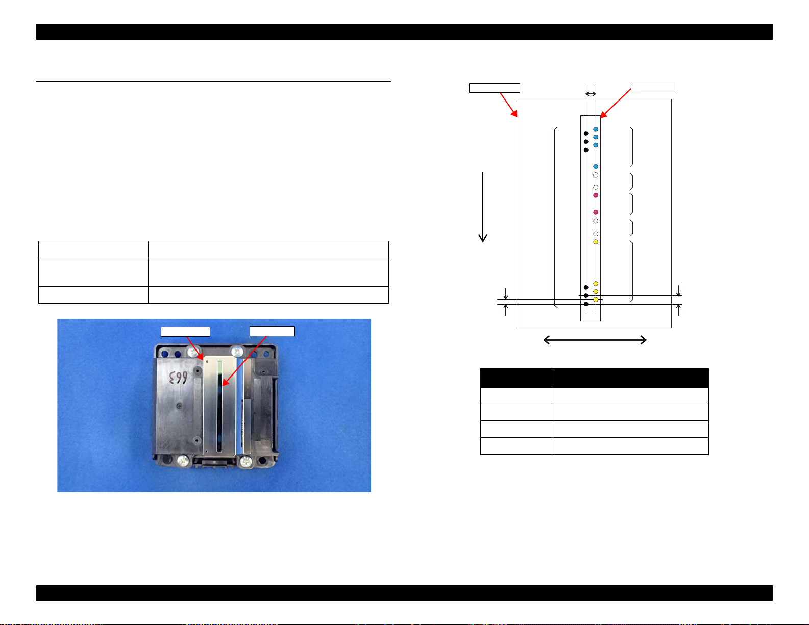
1.1.1 Print Head
μTFP1S head (p 12) is used for ET-4750/ET-4760/L6190/ST-4000 series/ET3750/ET-3760/L6170/ST-3000 series/ET-3700/ET-3710/L6160 series.
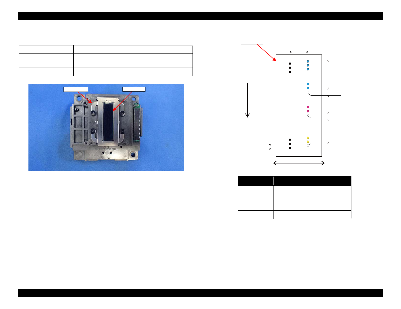
F2 head (p 13) is used for ET-2750/ET-2760/L4160/ST-2000 series/ET-2700/
L4150 series.
ET-4750/ET-4760/L6190/ST-4000 series/ET-3750/ET-3760/L6170/ST-
3000 series
Color Four colors: black (Bk), cyan (C), magenta (M), yellow (Y)
Number of nozzles 784 nozzles:
Nozzle pitch 300 dpi
/ET-3700/ET-3710/L6160 series
Table 1-1. Nozzle Configuration
400 nozzles for Bk, and 128 nozzles for each of Y, M, and C
Operating Principles Printer Mechanism Overview 12
Figure 1-1. μTFP1S Print Head appearance
Figure 1-2. Nozzle layout (seen from the rear side)
Confidential
EPSON ET-4750/4760/3750/3760/3700/3710/2750/2760/2700/L6190/L6170/L6160/L4160/L4150/ST-4000/ST-3000/ST-2000 series Revision G
Nozzle plate
Cover Head
Black
Column A Column B
Carriage movement direction
Paper feed direction
Column Color
ABk
B #1 - #60 Y
B #62 - #120 M
B #122 - #180 C
Yellow
Cyan
Magenta
Not used
Not used
Not used
Nozzle plate
ET-2750/ET-2760/L4160/ST-2000 series/ET-2700/L4150 series
Table 1-2. Nozzle Configuration
Color Four colors: black (Bk), cyan (C), magenta (M), yellow (Y)
Number of nozzles 357 nozzles:
180 nozzles for Bk, 59 nozzles for each Y, M, and C.
Nozzle pitch 180 dpi
0.071 mm
1/360 inch
5.9266 mm
42/180 inch
A#180
A#179
A#178
A#3
A#2
A#1
B#180
B#179
B#178
B#123
B#122
B#121
B#63
B#62
B#61
B#3
B#2
B#1
Figure 1-3. F2 Print Head appearance
Operating Principles Printer Mechanism Overview 13
Figure 1-4. Nozzle layout (seen from the rear side)
Confidential
EPSON ET-4750/4760/3750/3760/3700/3710/2750/2760/2700/L6190/L6170/L6160/L4160/L4150/ST-4000/ST-3000/ST-2000 series Revision G
CR Scale
CR Timing Belt
CR Unit
CR Motor
(Backside of the Main Frame)
CR Encoder Sensor
Section view
Main Frame
CR Unit
Main Frame
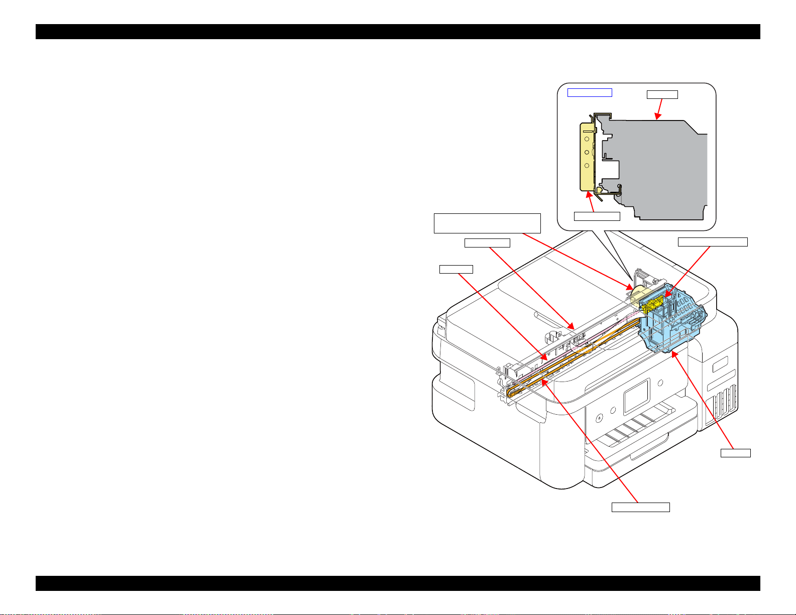
1.1.2 Carriage (CR) Mechanism
The major components of the carriage (CR) mechanism are the CR Unit, CR
Encoder Sensor, CR Scale, CR Motor, and CR Timing Belt. The CR
mechanism is a key mechanism to ensure stable print quality because printing
is performed by moving the CR Unit from side to side.
As shown on the right, Main Frame is holding the upper side and the lower side
of the CR Unit. The CR Unit is attached to the CR Timing Belt that is moved
by the CR Motor so that the assy can move from side to side to print. The
position and speed of the CR Unit are always monitored by the CR Encoder
Sensor and the CR Scale, and the CR Motor is controlled in accordance with
the information acquired by the CR Encoder Sensor.
Operating Principles Printer Mechanism Overview 14
Figure 1-5. Carriage (CR) mechanism
Confidential
EPSON ET-4750/4760/3750/3760/3700/3710/2750/2760/2700/L6190/L6170/L6160/L4160/L4150/ST-4000/ST-3000/ST-2000 series Revision G
Cassette
Slider Trans
Holder Cam Assy
PF Motor
PF Roller
Pick up Roller Assy
Intermediate roller
(inside the Duplex Unit)
EJ Roller
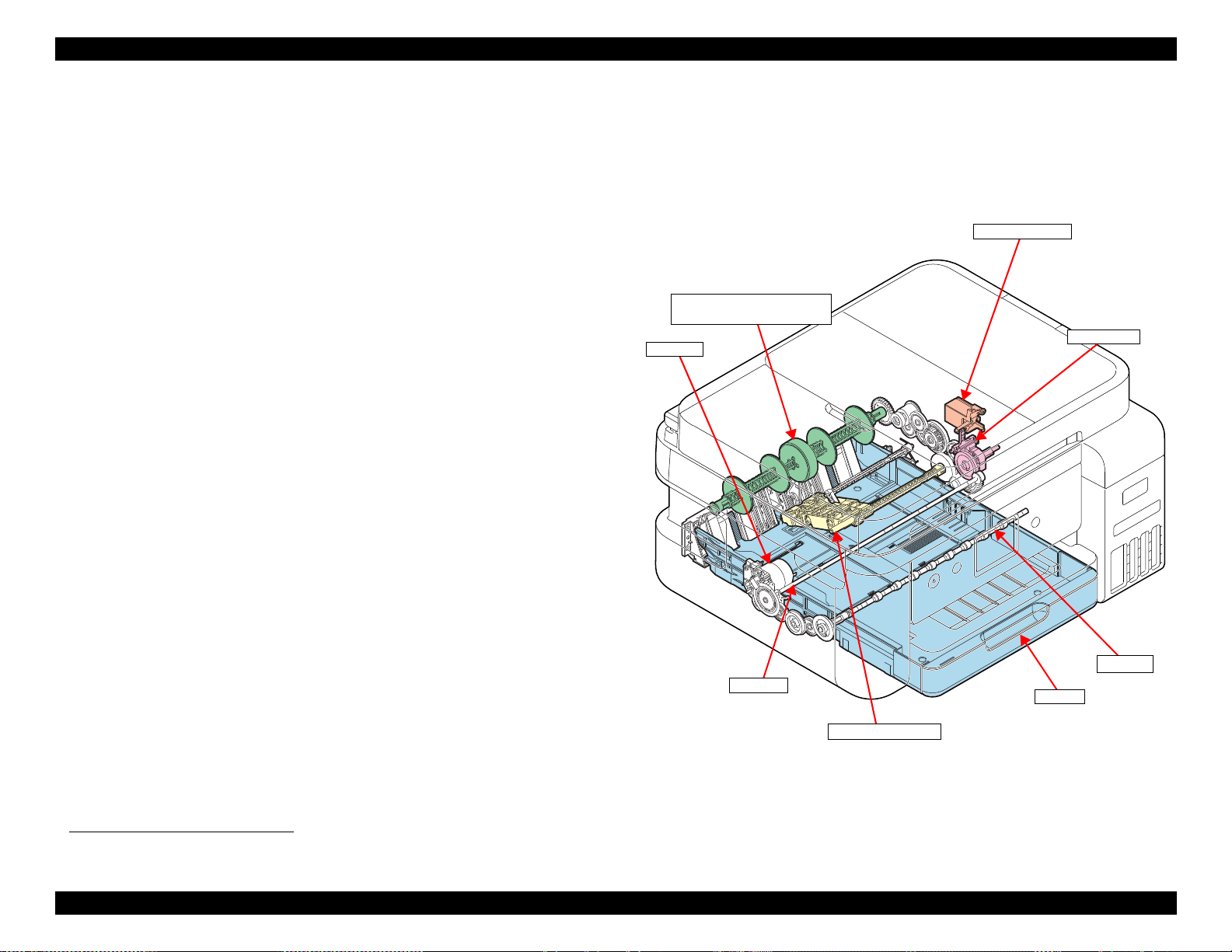
1.1.3 Paper Loading/Feed Mechanism
Paper loading mechanism differs between ET-4750/ET-4760/L6190/ST-4000
series/ET-3750/ET-3760/L6170/ST-3000 series/ET-3700/ET-3710/L6160
series and ET-2750/ET-2760/L4160/ST-2000 series/ET-2700/L4150 series.
ET-4750/ET-4760/L6190/ST-4000 series/ET-3750/ET-3760/L6170/ST-3000
series/ET-3700/ET-3710/L6160 series employ the front paper loading, and ET2750/ET-2760/L4160/ST-2000 series/ET-2700/L4150 series employ the rear
paper loading. The both paper loading mechanisms are driven by the PF Motor,
and the motor is also used for driving the paper feeding mechanism.
The printer is also equipped with a paper feeding mechanism for auto
duplexing as well as other existing products. The mechanism flips paper after
printing on the front side is finished, and feeds the paper to print on the back
side.
ET-4750/ET-4760/L6190/ST-4000 series/ET-3750/ET-3760/L6170/ST-
3000 series/ET-3700/ET-3710/L6160 series
A sheet of paper is fed inside the printer from the Paper Cassette by the Pick up
Roller Assy.
*1
Because the Pick up Roller Assy needs to be stopped each after it feeds a sheet
of paper, it is necessary to control the transmission of a drive force to the assy.
The control is achieved by the Slider Trans and the Holder Cam Assy. When
the Slider Trans is moved by the CR Unit, the state of engagement between the
transmission gear on the Trans Slider and the Pick up Roller driving gear
changes, which enables switching between transmitting the PF Motor driving
force to the Pick up Roller Assy and not transmitting it.
Even after the CR Unit is detached from the Slider Trans for printing, position
of the Slider Trans is kept by the Holder Cam Assy.
The paper fed by the Pick up Roller Assy is conveyed by the intermediate
roller, PF Roller, and EJ Roller which are included in the paper feeding
mechanism.
*1. See "1.3 Paper Loading/Feed Mechanism" (p 22) for more details.
Figure 1-6. Paper loading/feed mechanism (1)
Operating Principles Printer Mechanism Overview 15
Confidential
EPSON ET-4750/4760/3750/3760/3700/3710/2750/2760/2700/L6190/L6170/L6160/L4160/L4150/ST-4000/ST-3000/ST-2000 series Revision G
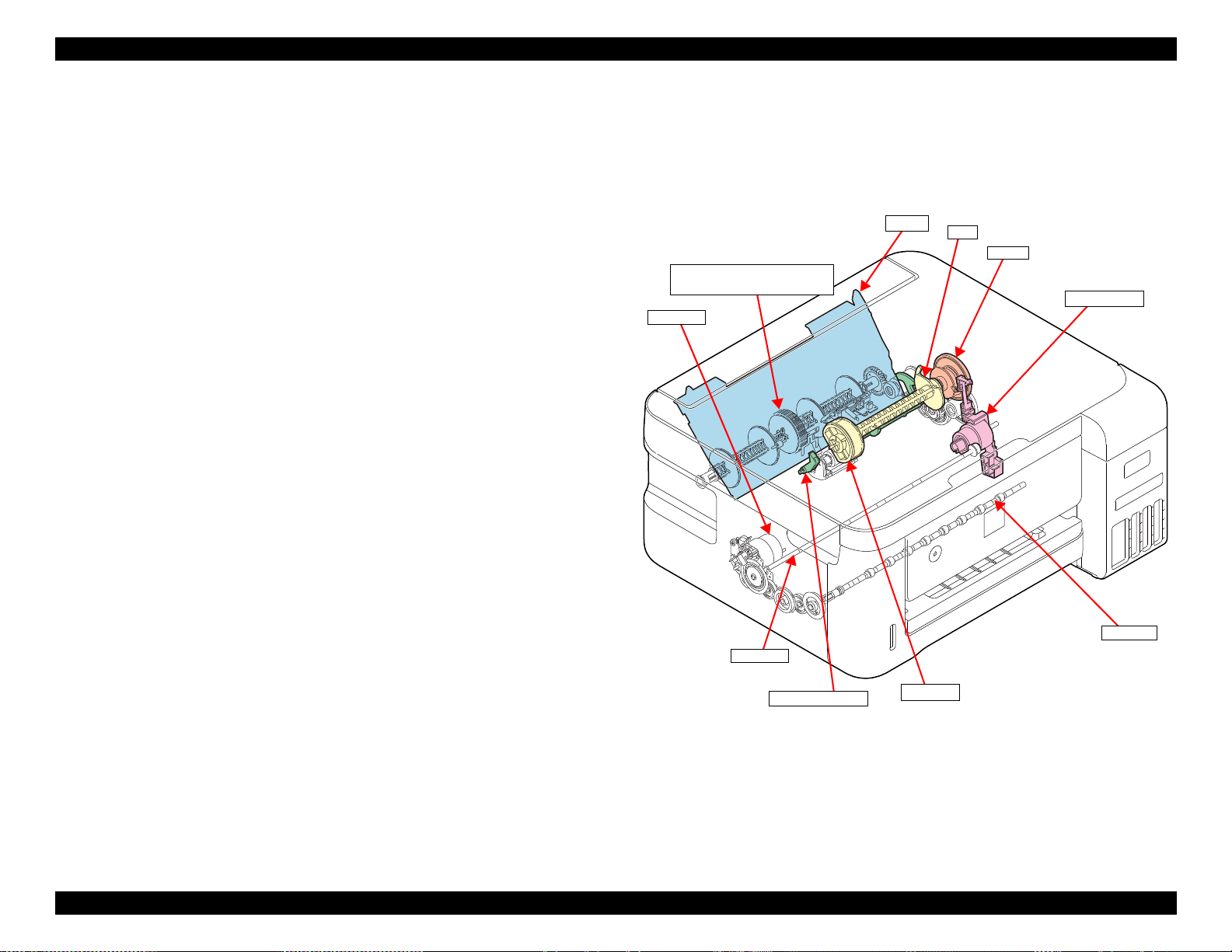
Paper Back Lever
Hopper
PF Motor
PF Roller
LD Roller
Intermediate roller
(inside the Duplex Unit)
EJ Roller
Change Lever
Clutch
Cam
ET-2750/ET-2760/L4160/ST-2000 series/ET-2700/L4150 series
Paper is fed inside the printer from the ASF Rear by the LD Roller.
The ASF Rear is equipped with a Hopper, Paper Back Lever, Change Lever,
LD Roller, and clutch. The Change Lever and the clutch work for transmitting
a driving force from the PF Motor to the LD Roller and for not transmitting it.
The Hopper and the Paper Back Lever driven by the cam on the LD Roller
Shaft prevent multi-feed and ensure accurate paper feeding.
Paper fed by the ASF Rear is conveyed by the PF Roller and the EJ Roller
which are included in the paper feeding mechanism.
Unlike the front paper loading, intermediate roller is used only when flipping
paper for duplex printing.
Figure 1-7. Paper loading/feed mechanism (2)
Operating Principles Printer Mechanism Overview 16
Confidential
EPSON ET-4750/4760/3750/3760/3700/3710/2750/2760/2700/L6190/L6170/L6160/L4160/L4150/ST-4000/ST-3000/ST-2000 series Revision G
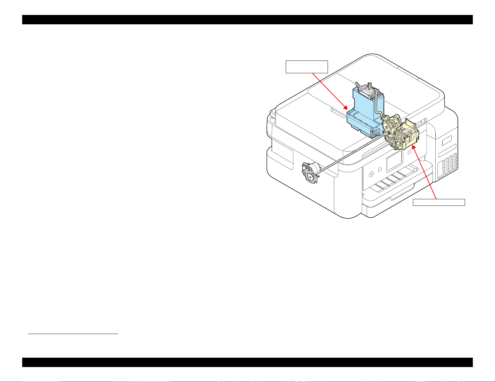
Ink system mechanism
Maintenance Box/
Porous Pad Assy
1.1.4 Ink System Mechanism
The major components of the ink system mechanism*1 are a cap, pump unit,
and waste ink tube.
The ink system mechanism employs the slide type capping. When the CR Unit
returns to its capping position (home position), the Print Head is capped. The
pump mechanism, wiper mechanism, and the CR Lock mechanism are driven
by the PF Motor to clean the Print Head.
Waste ink sucked when cleaning the Print Head is collected in the Maintenance
Box/Porous Pad Assy through the pump mechanism.
User replaceable Maintenance Box is installed to ET-4750/ET-4760/L6190/
ST-4000 series/ET-3750/ET-3760/L6170/ST-3000 series/ET-3700/ET-3710/
L6160 series. A CSIC mounted on the Maintenance Box keeps track of how
much waste ink has been collected.
On the other hand, the Porous Pad that cannot be replaced by user is installed to
ET-2750/ET-2760/L4160/ST-2000 series/ET-2700/L4150 series. The
EEPROM on the Main Board keeps track of how much waste ink has been
collected.
Figure 1-8. Ink system mechanism
*1. See "1.4 Ink System Mechanism" (p 33) for more details.
Operating Principles Printer Mechanism Overview 17
Confidential
EPSON ET-4750/4760/3750/3760/3700/3710/2750/2760/2700/L6190/L6170/L6160/L4160/L4150/ST-4000/ST-3000/ST-2000 series Revision G
A
1
B
C
2
3
4
5
6
7
8
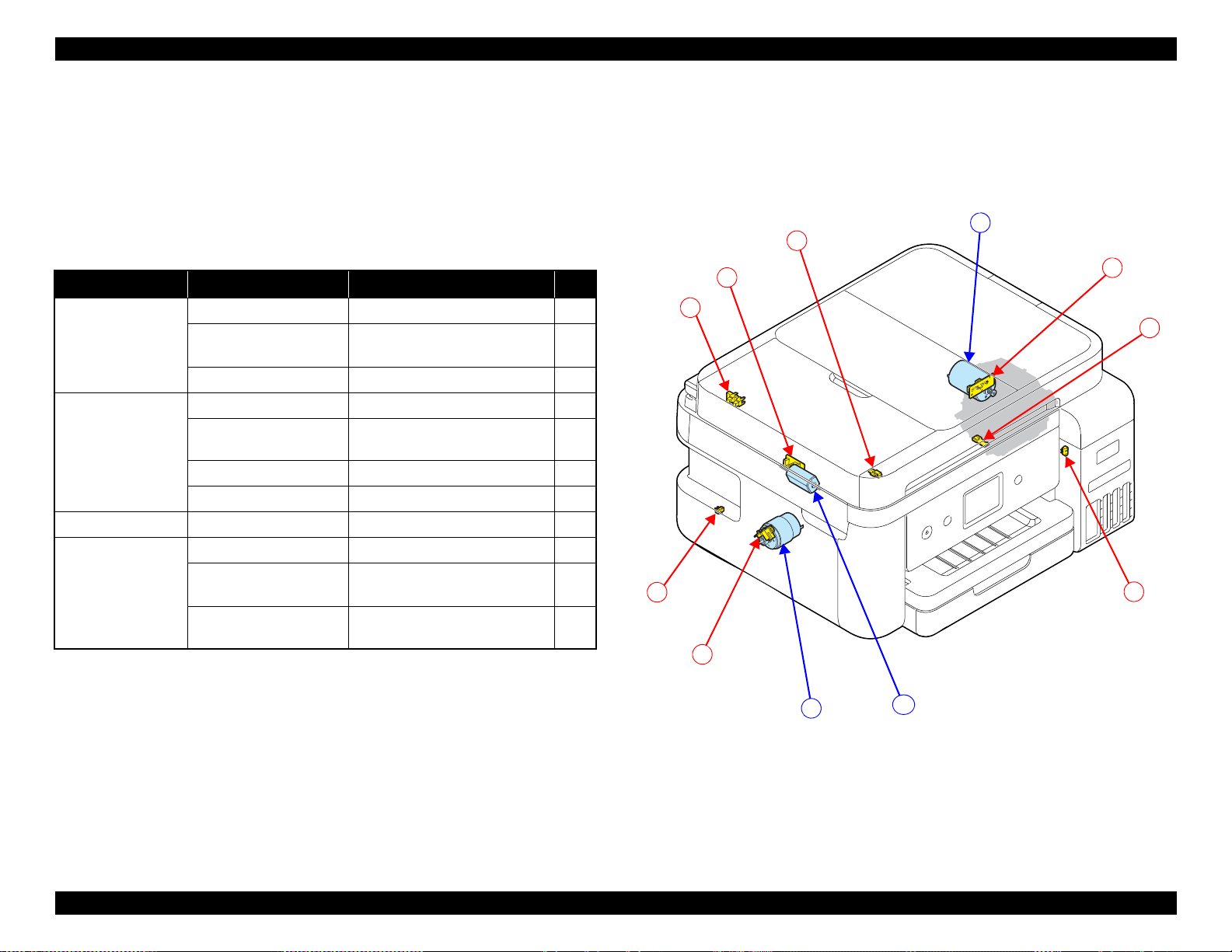
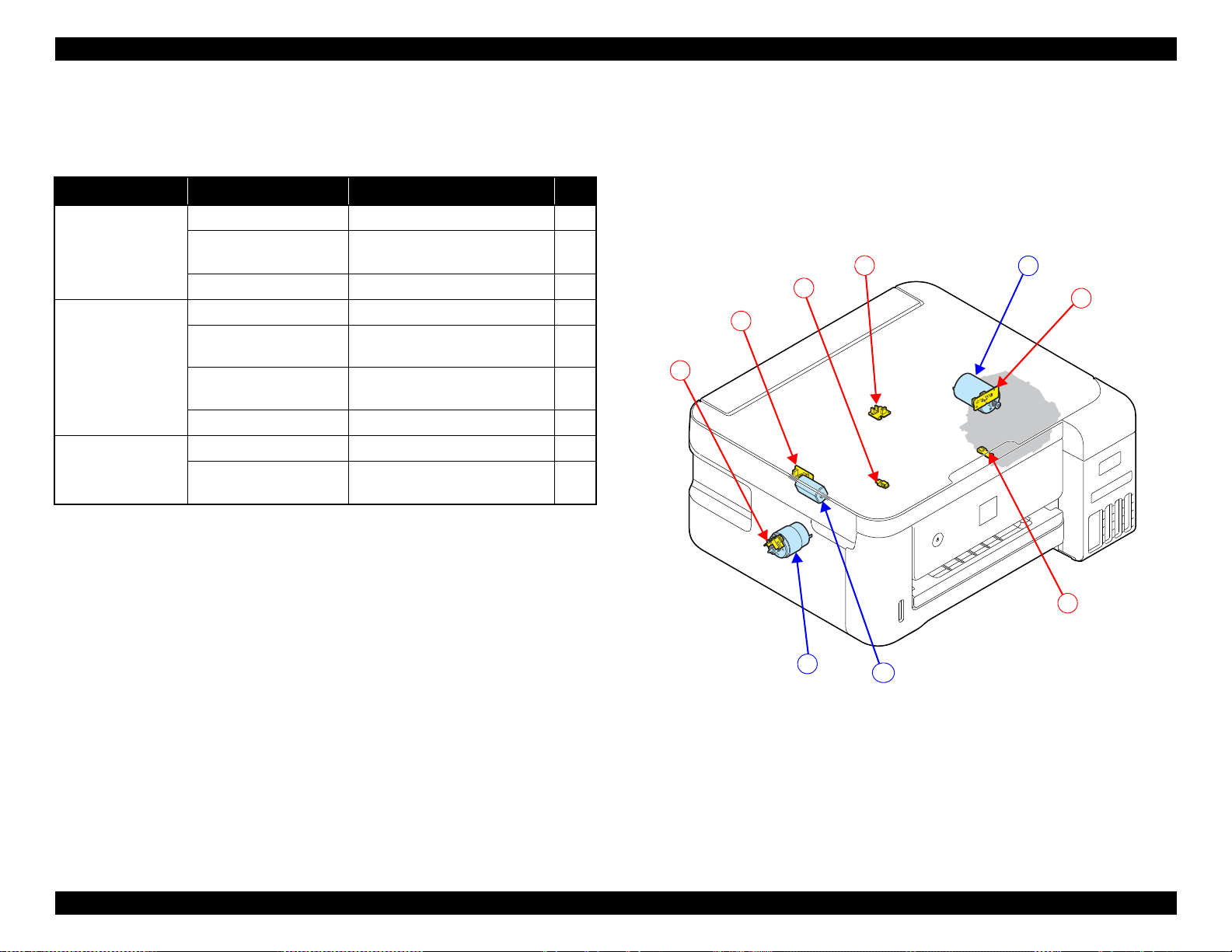
1.1.5 List of Motor and Sensor
This section describes the types and positions of the motors and sensors.
ET-4750/ET-4760/L6190/ST-4000 series/ET-3750/ET-3760/L6170/ST-
3000 series/ET-3700/ET-3710/L6160 series
Table 1-3. Motor and Sensor List
(ET-4750/ET-4760/L6190/ST-4000 series/ET-3750/ET-3760/L6170/ST-3000
series/ET-3700/ET-3710/L6160 series)
Mechanism name Motor/sensor name Motor/sensor type No.
Carriage
mechanism
CR Motor DC Motor A
CR Encoder Transmission-type photo
interrupter
PW Sensor Reflection-type photo interrupter 2
Paper loading/feed
mechanism
Others Ink Cover Open Sensor Mechanical contact 6
Scanner SCN Motor DC Motor C
PF Motor DC Motor B
PF Encoder Transmission-type photo
interrupter
Cassette Sensor Mechanical contact 4
PE Sensor Reflection-type photo interrupter 5
SCN Motor Encoder Transmission-type photo
interrupter
ADF PE Sensor Transmission-type photo
interrupter
1
3
7
8
Figure 1-9. List of motor and sensor
(ET-4750/ET-4760/L6190/ST-4000 series/ET-3750/ET-3760/L6170/ST-
3000 series/ET-3700/ET-3710/L6160 series)
Operating Principles Printer Mechanism Overview 18
Confidential
EPSON ET-4750/4760/3750/3760/3700/3710/2750/2760/2700/L6190/L6170/L6160/L4160/L4150/ST-4000/ST-3000/ST-2000 series Revision G
A
1
B
C
2
3
4
5
6
ET-2750/ET-2760/L4160/ST-2000 series/ET-2700/L4150 series
Table 1-4. Motor and Sensor List (ET-2750/ET-2760/L4160/ST-2000 series/ET-
2700/L4150 series)
Mechanism name Motor/sensor name Motor/sensor type No.
Carriage
mechanism
Paper loading/feed
mechanism
Scanner SCN Motor DC Motor C
CR Motor DC Motor A
CR Encoder Transmission-type photo
interrupter
PW Sensor Reflection-type photo interrupter 2
PF Motor DC Motor B
PF Encoder Transmission-type photo
interrupter
ASF Rear Paper existence
Sensor
PE Sensor Reflection-type photo interrupter 5
SCN Motor Encoder Transmission-type photo
Mechanical contact 4
interrupter
1
3
6
Figure 1-10. List of motor and sensor
(ET-2750/ET-2760/L4160/ST-2000 series/ET-2700/L4150 series)
Operating Principles Printer Mechanism Overview 19
Confidential
EPSON ET-4750/4760/3750/3760/3700/3710/2750/2760/2700/L6190/L6170/L6160/L4160/L4150/ST-4000/ST-3000/ST-2000 series Revision G
Scanner Unit
CIS Sensor
SCN Motor
ADF Unit
ADF PE Sensor
Pick up Roller
EJ Roller
PF Roller
SCN Motor
EJ Roller
Pick up Roller
Transmission
gear
ADF Document
Lever
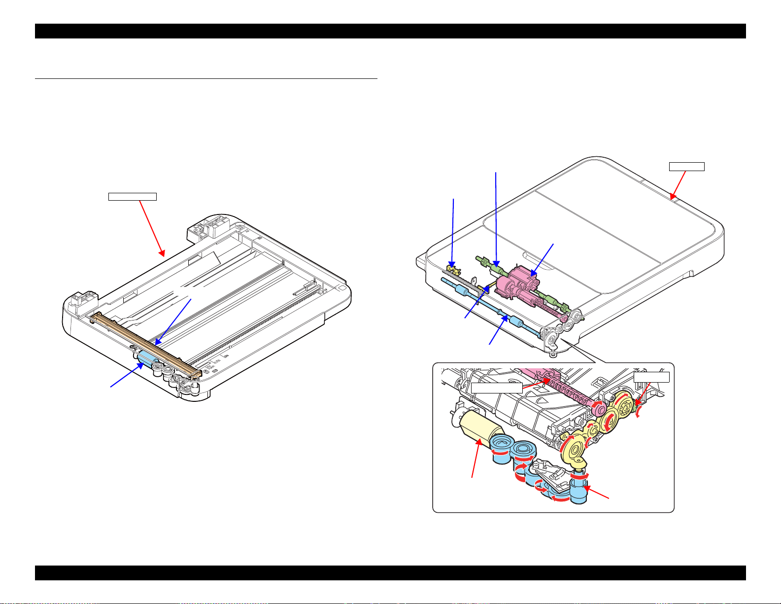
1.2 Scanner/ADF Overview
1.2.1 Scanner Mechanism
The scanner mechanism consists of a CIS sensor that scans documents and the
SCN motor that drives the scanner carriage. The CIS sensor and the SCN motor
are integrated as the scanner carriage, and it moves along the rail on the scanner
housing to scan documents.
1.2.2 ADF Mechanism (ET-4750/ET-4760/L6190/ST-4000 series/ET-3750/ET-3760/L6170/ST-3000 series only)
The PF Roller, EJ Roller, and Pick up Roller of the ADF mechanism are driven
by the SCN Motor. The drive force of the motor is transmitted through the
transmission gear. The ADF mechanism does not support auto duplex
scanning.
Figure 1-11. Scanner mechanism
Figure 1-12. ADF mechanism
Operating Principles Scanner/ADF Overview 20
Confidential
EPSON ET-4750/4760/3750/3760/3700/3710/2750/2760/2700/L6190/L6170/L6160/L4160/L4150/ST-4000/ST-3000/ST-2000 series Revision G
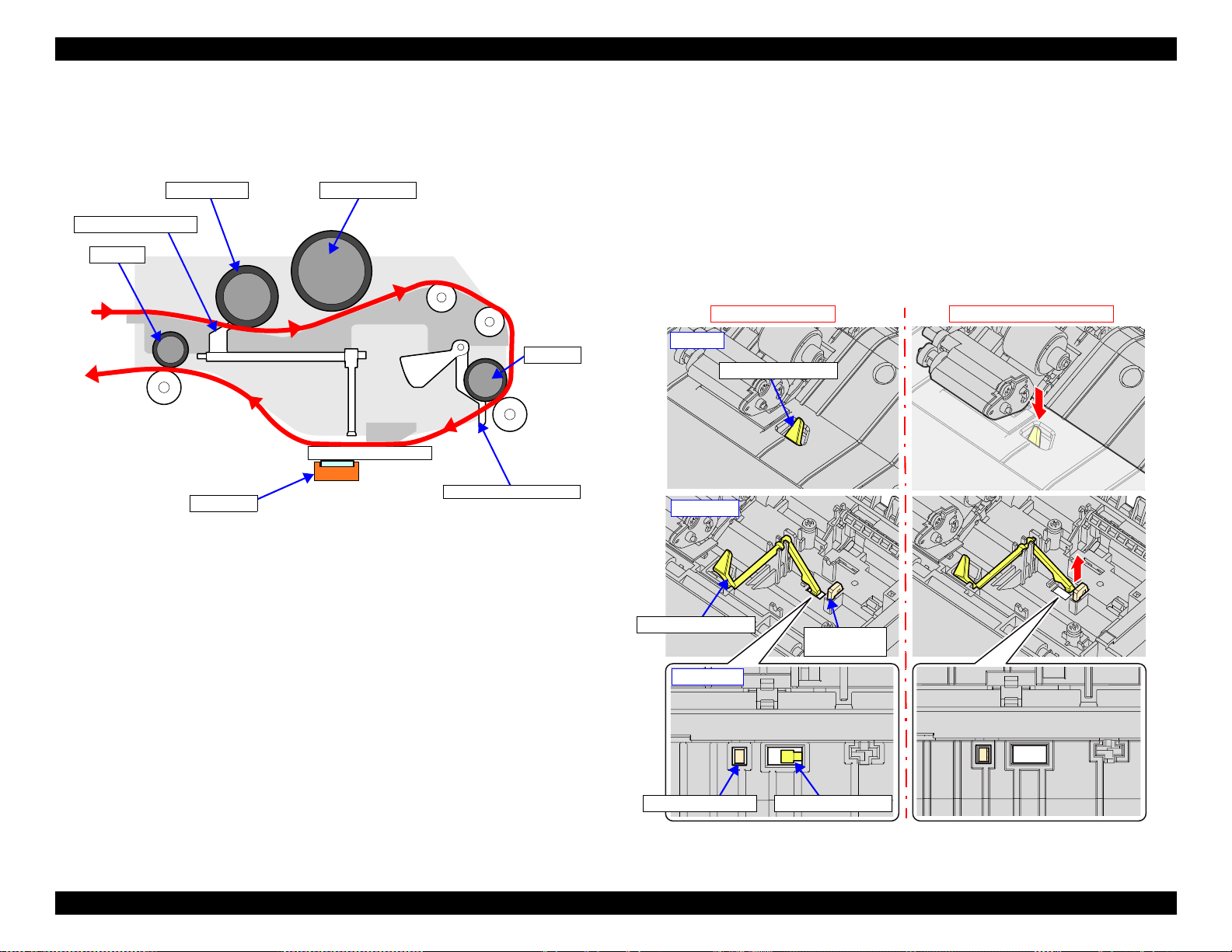
Pick up Roller Separation roller
PF Roller
EJ Roller
CIS Sensor
Lever of ADF PE Sensor
ADF Document Lever
No document on ADF
Document is present on ADF
ADF document lever
ADF document lever
Sub document
lever
Sub document lever ADF document lever
ADF top
ADF inside
ADF bottom
When scanning document, the document is fed inside the ADF as shown
below.
Figure 1-13. Document Feed Path
Presence or absence of document on the ADF is detected by the ADF
Document Lever and the scanner CIS Sensor. The lever moves up or down
depending on the presence or absence of document, and the end of the lever is
scanned by the CIS Sensor. According to the scan result, the printer determines
whether document is present or not.
Additionally, there is a Sub Document Lever beside the ADF Document Lever.
If the CIS Sensor cannot scan the end of the Sub Document Lever, the printer
determines that the scanner (SCN) unit is open or the CIS Sensor is
malfunctioning.
Operating Principles Scanner/ADF Overview 21
Figure 1-14. ADF document lever
Confidential

EPSON ET-4750/4760/3750/3760/3700/3710/2750/2760/2700/L6190/L6170/L6160/L4160/L4150/ST-4000/ST-3000/ST-2000 series Revision G
1.3 Paper Loading/Feed Mechanism
1.3.1 Overview
1.3.1.1 Paper Loading Method
Paper loading method differ between ET-4750/ET-4760/L6190/ST-4000
series/ET-3750/ET-3760/L6170/ST-3000 series/ET-3700/ET-3710/L6160
series and ET-2750/ET-2760/L4160/ST-2000 series/ET-2700/L4150 series,
but the both paper loading mechanisms are driven by the PF Motor.
Table 1-5. Paper Loading Method and Drive Force
Drive
force
(motor)
PF Motor PF encoder/
Motor control
PF scale
Front paper loading
• Turn the Slider Trans to
ASF mode, drive the
Pick up Roller Assy, and
load paper from the
cassette.
• Paper loaded from the
cassette is fed to the PF
Roller by the
intermediate roller
inside the duplex unit.
• Drive the PF Roller/EJ
Roller to convey the
paper.
Paper loading operation
model
Rear paper loading
model
• Drive the LD Roller and
load paper from the ASF
Rear.
• Drive the Hopper/Paper
Back Lever to prevent
multi-feed.
• Drive the PF Roller/EJ
Roller to convey the
paper.
• To flip paper for duplex
printing, drive the
intermediate roller
inside the duplex unit.
The paper is flipped and
then fed to the PF
Roller.
The following describes which paper loading method is used
for which model.
Front paper loading
ET-4750/ET-4760/L6190/ST-4000 series/ET-3750/ET3760/L6170/ST-3000 series/ET-3700/ET-3710/L6160
series/
Rear paper loading
ET-2750/ET-2760/L4160/ST-2000 series/ET-2700/L4150
series
Operating Principles Paper Loading/Feed Mechanism 22
Confidential
EPSON ET-4750/4760/3750/3760/3700/3710/2750/2760/2700/L6190/L6170/L6160/L4160/L4150/ST-4000/ST-3000/ST-2000 series Revision G
Intermediate roller
Pick up Roller Assy
PF Roller
EJ Roller
PF Motor
Holder Cam Assy
Slider Trans
Cassette
PF Encoder
Hopper
LD Roller
Change Lever
Clutch
PF Encoder
PF Roller
EJ Roller
Stacker
Front paper loading model
Rear paper feeding model
Figure 1-15. Paper loading/feed mechanism
Operating Principles Paper Loading/Feed Mechanism 23
Confidential
EPSON ET-4750/4760/3750/3760/3700/3710/2750/2760/2700/L6190/L6170/L6160/L4160/L4150/ST-4000/ST-3000/ST-2000 series Revision G
Cassette
EJ Roller
Star Wheel
Holder Assy
PF Roller
Intermediate roller
PE Sensor
Pick up Roller Assy
Stacker
EJ Roller
Star Wheel
Holder Assy
PF Roller
PE Sensor
LD Roller
Hopper
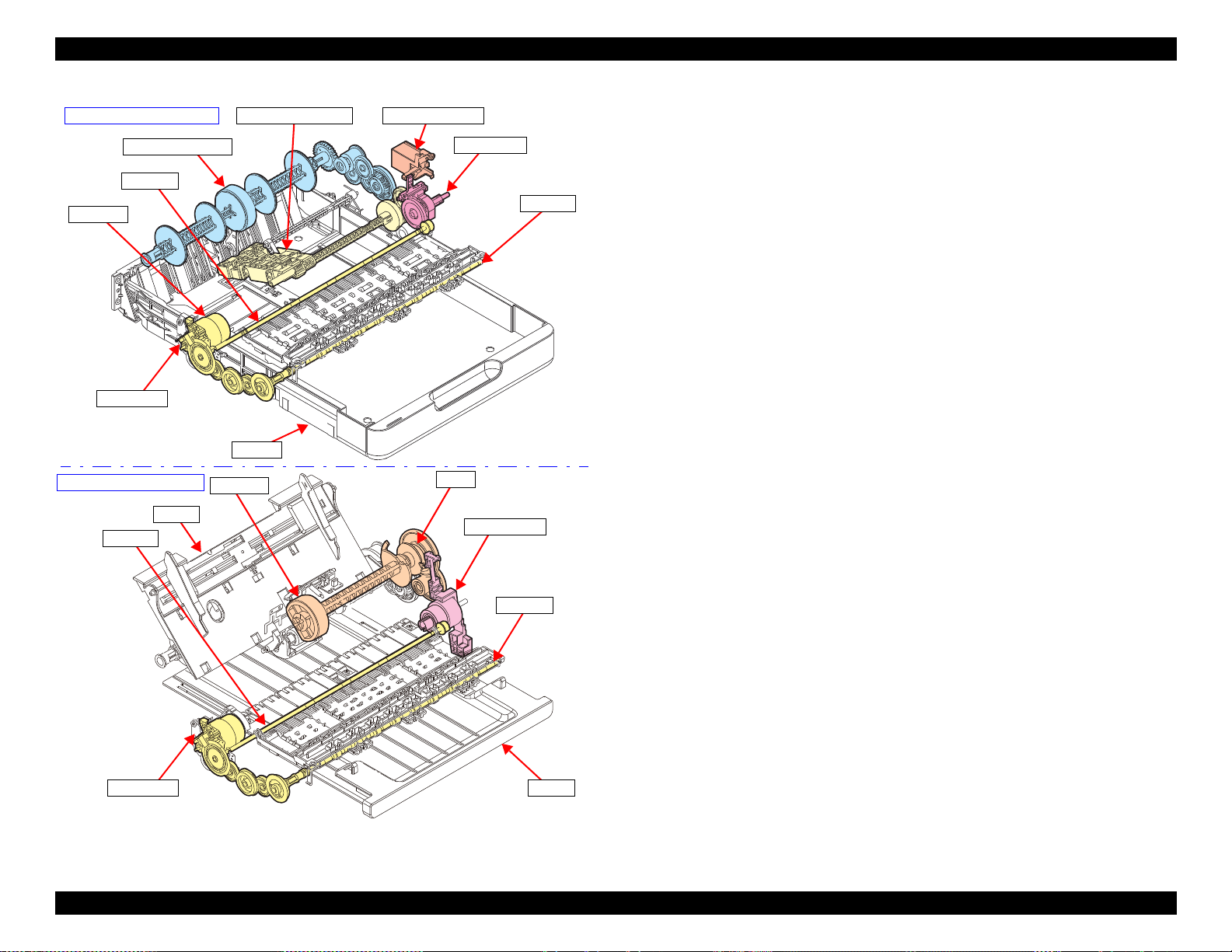
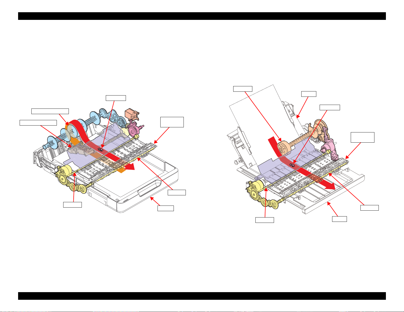
1.3.1.2 Paper Feed Path
1.3.1.2.1 Front Paper Loading
Paper loaded into the cassette is fed to the intermediate roller by the Pick up
Roller Assy, and then arrives at the PE Sensor position.
Next, skew is corrected, and printing on the paper is performed while the paper
is being fed by the PF Roller and EJ Roller/Star Wheel Holder Assy, then the
paper is ejected to the Stacker.
1.3.1.2.2 Rear Paper Loading
Paper put on the Hopper is fed by the LD Roller and arrives at the PE Sensor
position.
Next, skew is corrected, and printing on the paper is performed while the paper
is being fed by the PF roller and EJ Roller/Star Wheel Holder Assy, then the
paper is ejected to the Stacker.
Operating Principles Paper Loading/Feed Mechanism 24
Figure 1-16. Paper feed path of front paper loading
Figure 1-17. Paper feed path of rear paper loading
Confidential
EPSON ET-4750/4760/3750/3760/3700/3710/2750/2760/2700/L6190/L6170/L6160/L4160/L4150/ST-4000/ST-3000/ST-2000 series Revision G
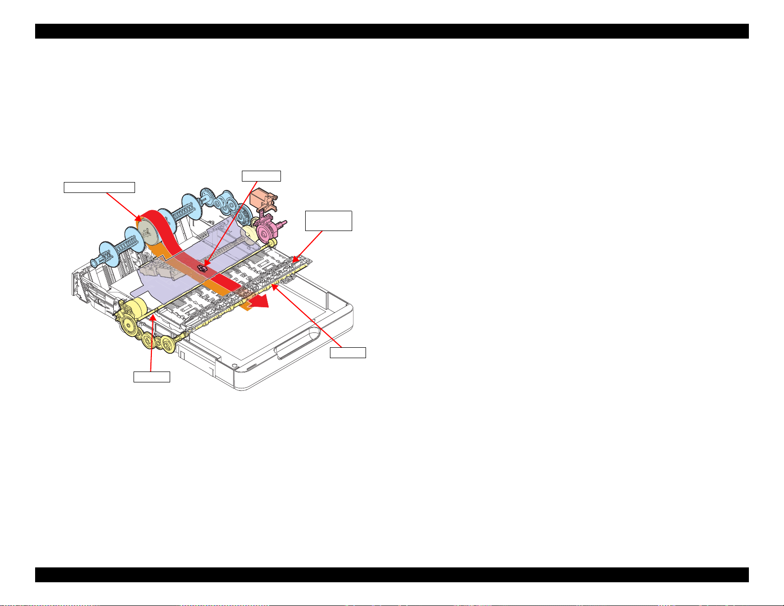
EJ Roller
Star Wheel
Holder Assy
PF Roller
PE Sensor
Intermediate roller
1.3.1.2.3 Paper Loading Path for Auto Duplex Printing
When printing on one side is finished, the printer waits for the ink on the one
side to dry keeping the paper nipped between the PF Roller and Driven Roller.
After a predetermined drying time has passed, the PF Roller and EJ Roller are
rotated in the reverse direction to pull the paper inside the auto duplex unit.
When the leading edge of the paper is detected by the PE Sensor, skew is
corrected, and then printing on the back side is performed.
Figure 1-18. Paper feed path for auto duplex printing (back side printing)
Operating Principles Paper Loading/Feed Mechanism 25
Confidential
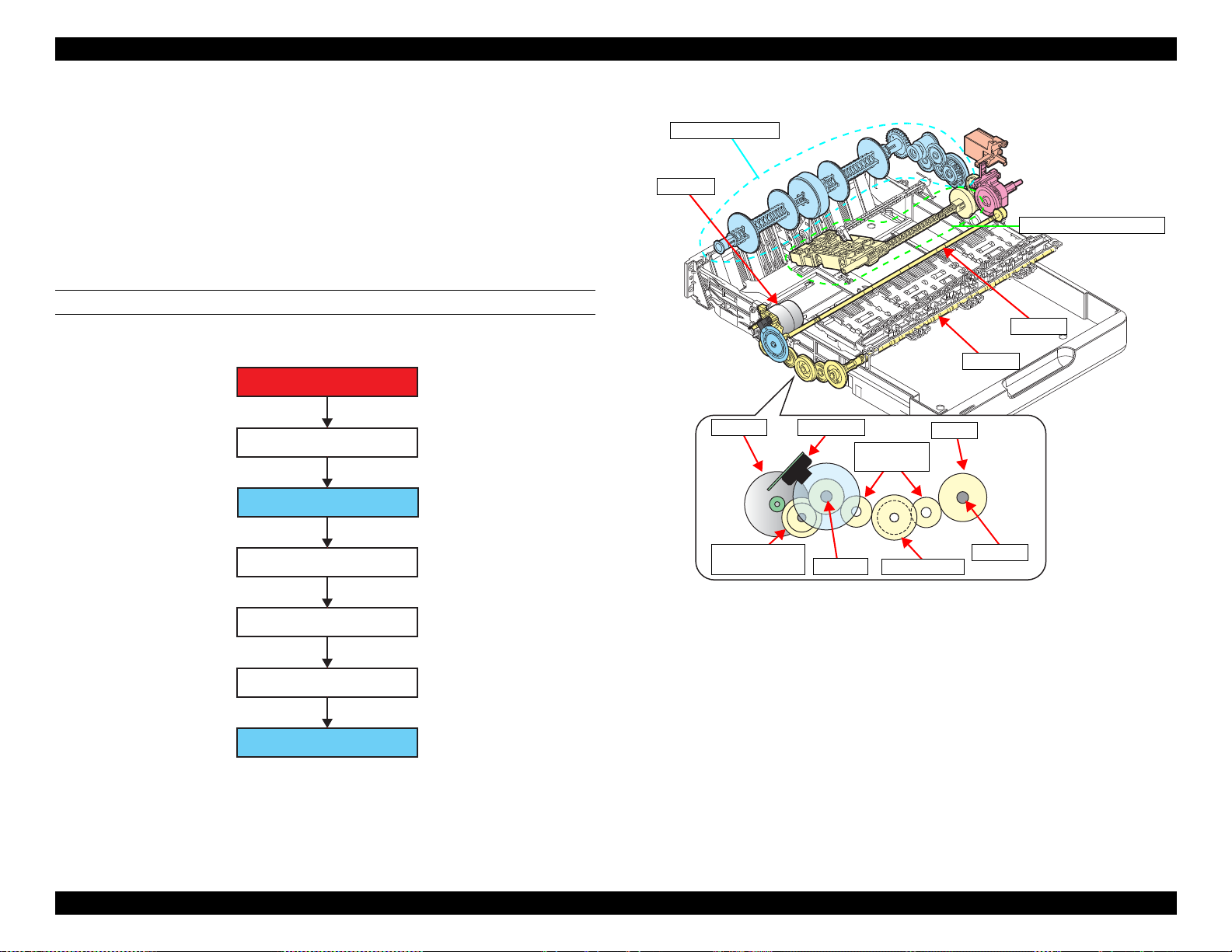
EPSON ET-4750/4760/3750/3760/3700/3710/2750/2760/2700/L6190/L6170/L6160/L4160/L4150/ST-4000/ST-3000/ST-2000 series Revision G
PF Motor
Compound gear PF1
PF Roller
Spur gear PF1
Spur gear PF2
EJ Roller
Spur gear PF1
PF Roller
PF Motor PF Encoder
Compound gear
PF1
Spur gear PF2
Spur gear
PF1
EJ gear
EJ Roller
PF Roller
EJ Roller
Duplex unit system
Pick up Roller Assy system
PF Motor
1.3.2 Operation Principle
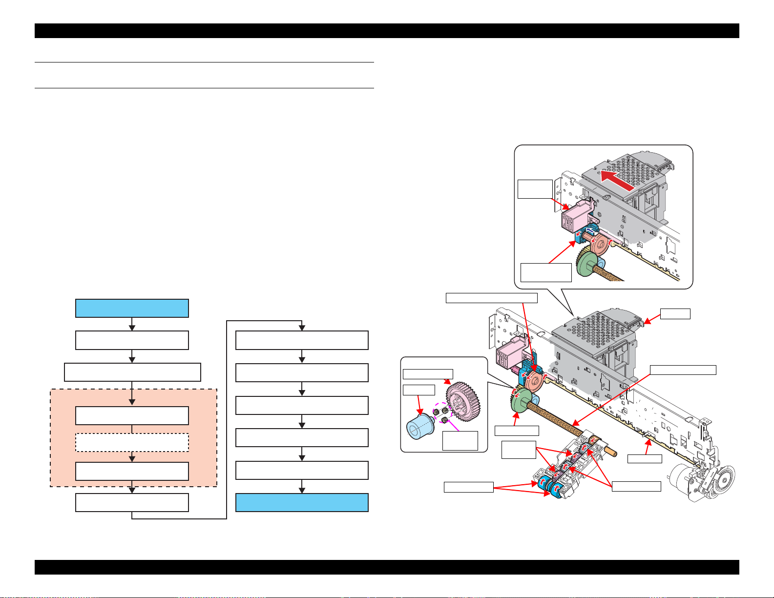
1.3.2.1 Drive Path
1.3.2.1.1 Drive Path of Front Paper Loading Model
The drive force of the PF Motor is transmitted to the PF Roller and EJ Roller
through the compound gear and the spur gear, and then transmitted from the PF
Roller to the paper feed mechanism. There are two drive paths; duplex unit
system
DRIVE PATH FROM PF MOTOR TO PF ROLLER/EJ ROLLER
(p 27) and Pick up Roller Assy system (p 28).
Figure 1-20. Drive path from PF Motor to PF Roller/EJ Roller (2)
Figure 1-19. Drive path from PF Motor to PF Roller/EJ Roller (1)
Operating Principles Paper Loading/Feed Mechanism 26
Confidential
EPSON ET-4750/4760/3750/3760/3700/3710/2750/2760/2700/L6190/L6170/L6160/L4160/L4150/ST-4000/ST-3000/ST-2000 series Revision G
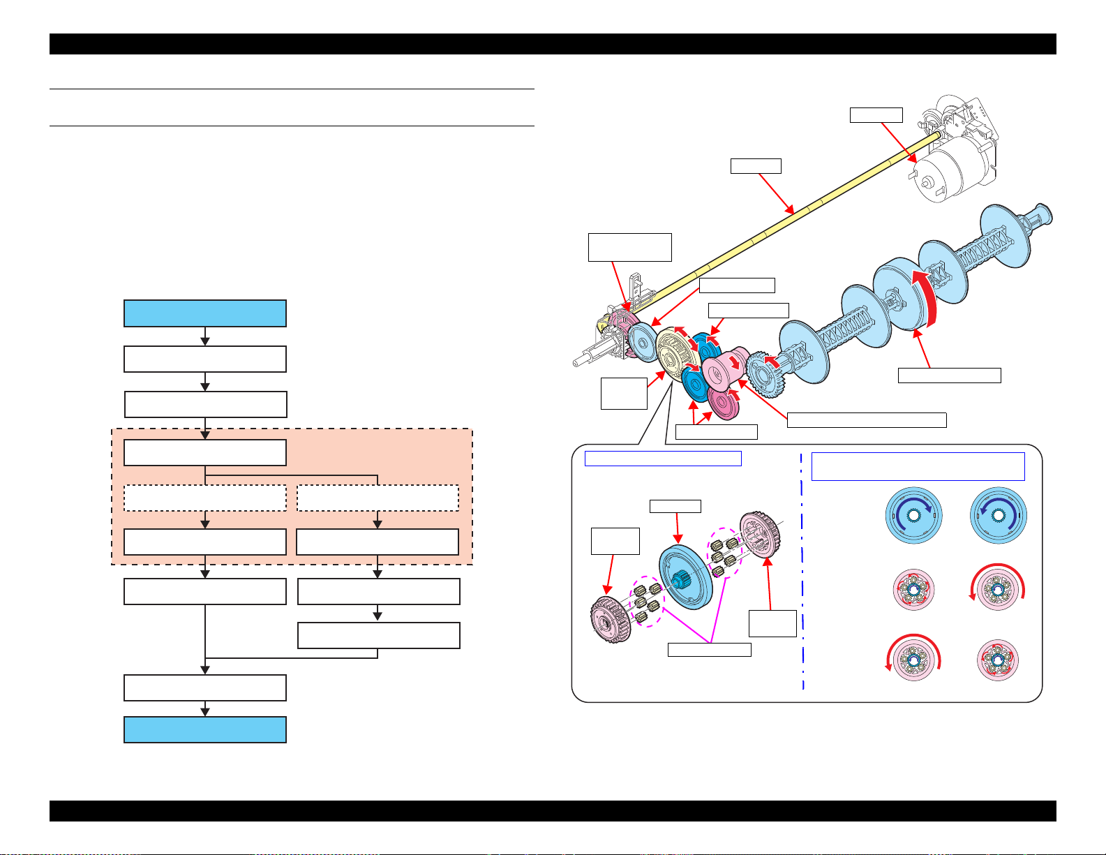
PF Roller (spur gear 9)
Compound gear 28.8-14.4
Spur gear 22.8
One way clutch
External gear B (80 digit side)
Intermediate roller
Spur gear 17.28
Sun gear
Planetary gear (x5)
Planetary gear (x5)
External gear A (0 digit side)
Spur gear 17.28
Spur gear 17.28
Spur gear 16/spur gear duplex
One way
clutch
PF Roller
Intermediate Roller
PF Motor
Structure of one way clutch
Planetary gear
Sun gear
External
gear A
External
gear B
External
gear A
External
gear B
Sun gear
Rotational direction of sun gear and motion
of external gear seen from 0 digit side
Idle
Idle
Clockwise
Counterclockwise
Rotate
Rotate
Compound gear
28.8-14.4
Spur gear 22.8
Spur gear 17.28
Spur gear 17.28
Spur gear 16/Spur gear duplex
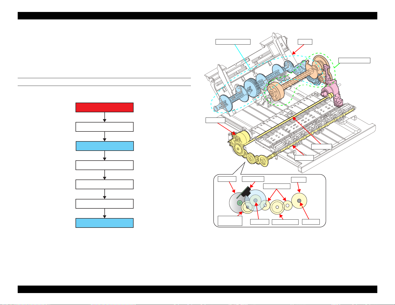
DRIVE PATH FROM PF ROLLER TO INTERMEDIATE ROLLER
(DUPLEX UNIT SYSTEM)
The intermediate roller always rotates in the paper feed direction because of the
one way clutch, regardless of the PF roller rotational direction.
The one way clutch is consist of the sun gear, the external gear (x2) on both
sides of the sun gear, and the planetary gear (x5 each) inside the external gear.
When the sun gear rotates, either one of the external gears idle being
disengaged from the planetary gears, while the external gear on the other side
rotates being engaged with the planetary gears. In this way, the one way clutch
is designed to rotate either one of the two external gears at a time, and which
one to rotate depends on the rotational direction of the sun gear.
Figure 1-21. Drive Path From PF Roller to Intermediate Roller (1)
Operating Principles Paper Loading/Feed Mechanism 27
Figure 1-22. Drive Path From PF Roller to Intermediate Roller (2)
Confidential
EPSON ET-4750/4760/3750/3760/3700/3710/2750/2760/2700/L6190/L6170/L6160/L4160/L4150/ST-4000/ST-3000/ST-2000 series Revision G
PF Roller (spur gear 9)
Compound gear 28.8-14.4
Spur gear 17.6 (Slider Trans)
One way clutch
Sun gear
Planetary gear (x3)
External gear
Spur gear 28
Pick up drive shaft
Spur gear 16B
Spur gear 16
Spur gear 16B
Spur gear 16
Pick up Roller
One way clutch
When drive force
of P F M ot or is not
transmitted
Spur gear 17.6
(Slider Trans)
Pick up drive shaft
Spur gear
16
Spur gear 16B
PF Roller
Spur gear 28
Compound gear 28.8-14.4
CR Unit
Planetary
gear
Sun gear
External gear
Holder
Cam Assy
Pick up Roller
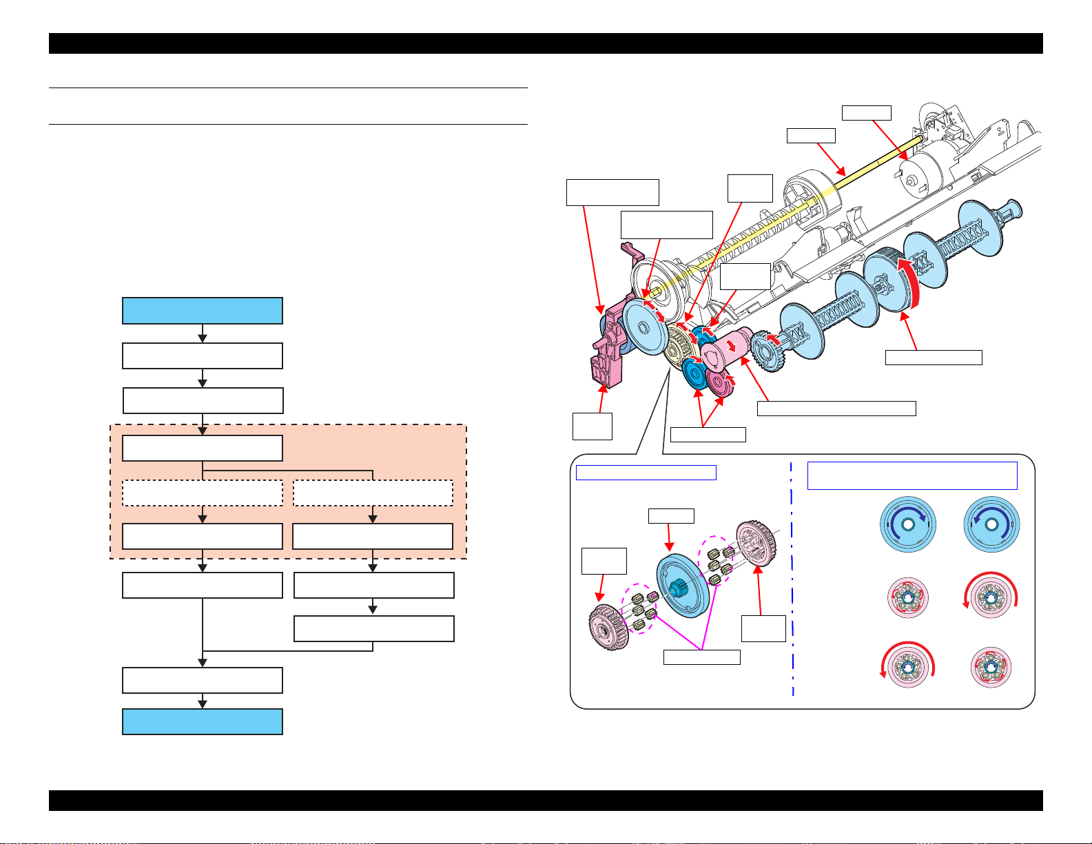
DRIVE PATH FROM PF ROLLER TO PICK UP ROLLER (PICK UP ROLLER
ASSY SYSTEM)
If the Pick up Roller Assy is always driven by the PF motor, it continues
feeding paper without stopping regardless of the progress of printing on the
previous sheet. To prevent this, the Slider Trans interrupts the motor drive to
the Pick up Roller Assy when the assy needs to stop.
While the Pick up Roller Assy needs to move, the Slider Trans is pulled toward
the opposite side of the carriage home with the tension spring. The
transmission gear interlocked with the Slider Trans engages with the Pick up
Roller driving gear (one way clutch) that moves the Pick up Roller Assy, so the
Pick up Roller Assy can be driven by the PF Motor. If the CR Unit pushes the
Change Lever to the 0 digit side, the transmission gear disengages from the one
way clutch. As a result, the driving force of the PF Motor is shut down.
The CR Unit pushes the Slider Trans to the 0 digit side to stop the Pick up
Roller Assy after a sheet of paper is fed into the printer, however, the CR Unit
cannot stay at the position because it needs to move for printing. Therefore,
instead of the CR Unit, the Change Lever’s disengaged status is kept by the
cam of the Holder Cam Assy during printing.
The one way clutch controls the Pick up Roller to rotate only in the paper feed
direction. The operation principle and the structure are basically the same with
the one used in the drive path to the intermediate roller
(p 27). Therefore, while
the PF Roller is rotating in the direction opposite to the paper feed direction,
the Pick up Roller does not rotate even when the drive force is transmitted
through the Slider Trans.
Operating Principles Paper Loading/Feed Mechanism 28
Figure 1-23. Drive path from PF roller to Pick up Roller Assy (1)
Figure 1-24. Drive path from PF roller to Pick up Roller Assy (2)
Confidential
EPSON ET-4750/4760/3750/3760/3700/3710/2750/2760/2700/L6190/L6170/L6160/L4160/L4150/ST-4000/ST-3000/ST-2000 series Revision G
PF Motor
Compound gear PF1
PF Roller
Spur gear PF1
Spur gear PF2
EJ Roller
Spur gear PF1
PF Roller
PF Motor
PF Encoder
Compound
gear PF1
Spur gear PF2
Spur gear PF1
EJ gear
EJ Roller
PF Roller
EJ Roller
Duplex unit system
ASF Rear system
PF Motor
Hopper
1.3.2.1.2 Drive Path of Rear Paper Loading Model
The drive path of the rear paper loading model is mostly the same with the
front paper loading model. The driving force of the PF Roller is transmitted to
the PF Roller and the EJ Roller through the compound gear and the spur gear,
and then transmitted from the PF Roller to the paper feed mechanism. There
are two drive paths; duplex unit system
(p 30) and ASF Rear system (p 31).
DRIVE PATH FROM PF MOTOR TO PF ROLLER/EJ ROLLER
Figure 1-25. Drive path from PF Motor to PF Roller/EJ Roller (1)
Figure 1-26. Drive path from PF Motor to PF Roller/EJ Roller (2)
Operating Principles Paper Loading/Feed Mechanism 29
Confidential
EPSON ET-4750/4760/3750/3760/3700/3710/2750/2760/2700/L6190/L6170/L6160/L4160/L4150/ST-4000/ST-3000/ST-2000 series Revision G
PF Roller (spur gear PF)
Compound gear 27.2-22.2
Compound gear 38.4-15.6
One way clutch
External gear B (80 digit side)
Intermediate roller
Spur gear 21.6
Sun gear
Planetary gear (x5)
Planetary gear (x5)
Spur gear 21.6
Spur gear 21.6
Spur gear16/spur gear duplex
External gear A (0 digit side)
One way
clutch
PF Roller
Intermediate roller
PF Motor
Planetary gear
Sun gear
External
gear A
External
gear B
External
gear A
External
gear B
Sun gear
Rotate
Idle
Clockwise
Counterclockwise
Idle
Rotate
Compound gear
38.4-15.6
Spur gear 21.6
Spur gear
21.6
Spur gear 16/Spur gear duplex
Compound gear
27.2-22.2
Change
Lever
Structure of one way clutch
Rotational direction of sun gear and motion
of external gear seen from 0 digit side
DRIVE PATH FROM PF ROLLER TO INTERMEDIATE ROLLER
(DUPLEX UNIT SYSTEM)
The intermediate roller always rotates in the paper feed direction because of the
one way clutch, regardless of the PF roller rotational direction.
The one way clutch is consist of the sun gear, the external gear (x2) on both
sides of the sun gear, and the planetary gear (x5 each) inside the external gear.
When the sun gear rotates, either one of the external gears idle being
disengaged from the planetary gears, while the external gear on the other side
rotates being engaged with the planetary gears. In this way, the one way clutch
is designed to rotate either one of the two external gears at a time, and which
one to rotate depends on the rotational direction of the sun gear.
Figure 1-27. Drive Path From PF Roller to Intermediate Roller (1)
Operating Principles Paper Loading/Feed Mechanism 30
Figure 1-28. Drive Path From PF Roller to Intermediate Roller (2)
Confidential
 Loading...