

Page 1
SERVICE MANUAL
Business Projector
EB-S01/W01/X14G/S11/X11/S02/S02H
EB-X02/W02/S12/S12H/X12/W12/X14
Home Projector
EH-TW480
CONFIDENTIAL
Page 2

EB-S01/W01/X14G/S11/X11/S0 2/S02H/X02/W02/S12/S12H /X 1 2/ W 12 /X1 4 EH- TW 4 8 0
CONFIDENTIAL
NOTICE
All rights reserved. No part of this manual may be reproduced, stored in retrieval system, or transmitted in any form or by any means, electronic, mechanical, photocopying,
recording, or otherwise, without prior written permission of SEIKO EPSON CORPORATION.
The contents of this manual should be handled with sufficient consideration for confidentiality reasons.
After publication of this manual, the parts and mechanism may be subject to change for improvement of their performance. Therefore, note that the descriptions given in this
manual may not coincide with the actual machine.
Other company or product names used herein are for identification purpose only and may be trademarks or registered trademarks of their respective owners. EPSON disclaims
any and all rights in those marks.
General Notice: Other product names used herein are for identification purpose only and may be trademarks or registered trademarks of their
respective owners. EPSON disclaims any and all rights in those marks.
Copyright © 2012 SEIKO EPSON CORPORATION.
SEIKO EPSON 2 Revision C
Page 3

EB-S01/W01/X14G/S11/X11/S0 2/S02H/X02/W02/S12/S12H /X 1 2/ W 12 /X1 4 EH- TW 4 8 0
CONFIDENTIAL
About This Manual
This manual describes basic functions, theory of electrical and mechanical operations, maintenance and repair procedures of the product. The instructions and procedures included
herein are intended for the experienced repair technicians, and attention should be given to the precautions on the preceding pages.
Manual Configuration
CHAPTER 1. PRODUCT DESCRIPTIONS
Provides a general overview and specifications of the product.
CHAPTER 2. TROUBLESHOOTING
Describes the step-by-step procedures for the troubleshooting.
CHAPTER 3. DISASSEMBLY / ASSEMBLY
Describes the step-by-step procedures for disassembling and assembling the product.
CHAPTER 4. MAINTENANCE
Describes the points to be checked and the step-by-step procedures to inspect the troubling location from errors or abnormal phenomena of the
projected image.
CHAPTER 5. APPENDIX
Provides preventive maintenance procedures for servicing the product.
SEIKO EPSON 3 Revision C
Page 4
EB-S01/W01/X14G/S11/X11/S0 2/S02H/X02/W02/S12/S12H /X 1 2/ W 12 /X1 4 EH- TW 4 8 0
CONFIDENTIAL
IMPORTANT PRECAUTIONS IN SAFETY AND MAINTENANCE PERFORMANCE
Here describes the important points to keep in mind in repair and maintenance performance.
SYMBOLS
To prevent injury to the repair technicians and to protect the devices, the categorized safety instructions are provided in this manual with the symbols below. Be sure
to read and understand their meanings before proceeding to the next section.
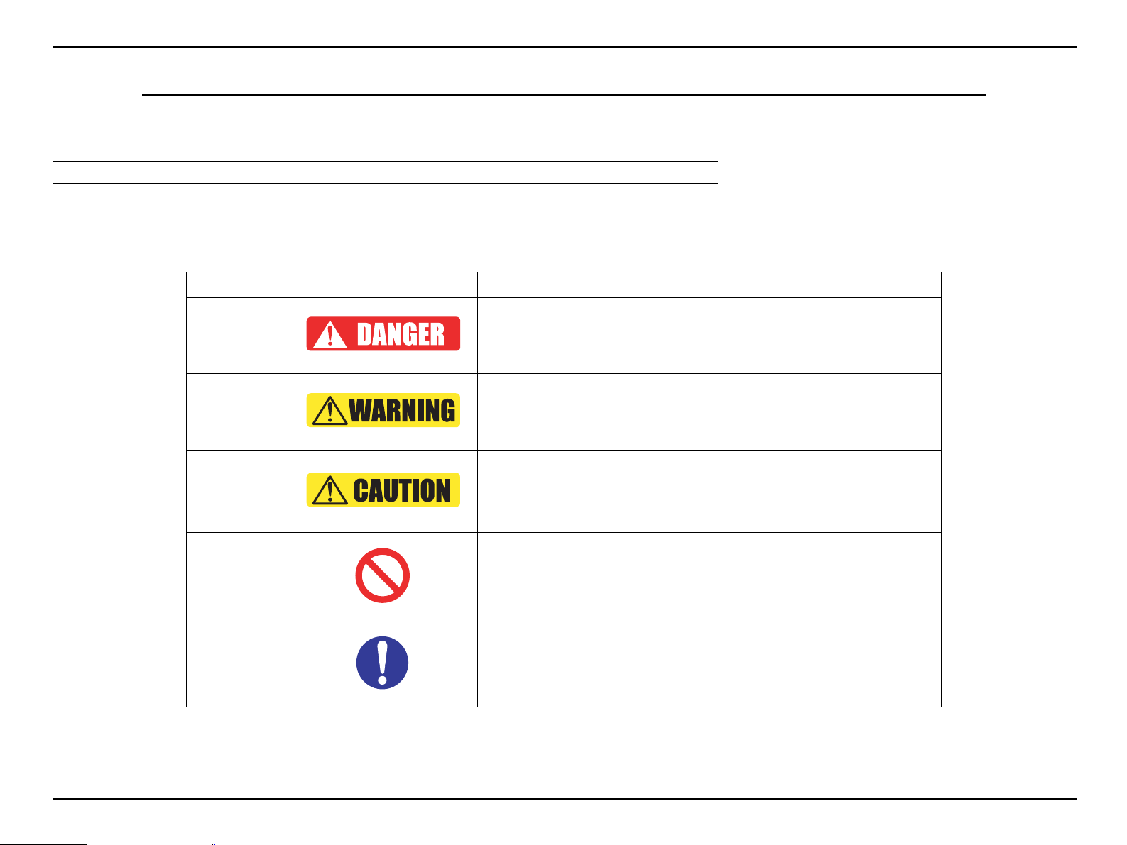
Category
Danger
Warning
Caution
Prohibited
Matter
Instruction
Symbol Meaning
Indicates an extremely hazardous operation which, if ignored or operated
incorrectly, could result in serious or fatal personal injury.
Indicates a potentially hazardous operation which, if ignored or operated
incorrectly, could result in serious or fatal personal injury.
Indicates a potentially hazardous operation which, if ignored or operated
incorrectly, could result in minor injury or damage to equipment.
Indicates a prohibited action or operation in repair and maintenance
performance.
Indicates a compulsory action or operation that must be carried out in repair and
maintenance performance.
SEIKO EPSON 4 Revision C
Page 5
EB-S01/W01/X14G/S11/X11/S0 2/S02H/X02/W02/S12/S12H /X 1 2/ W 12 /X1 4 EH- TW 4 8 0
CONFIDENTIAL
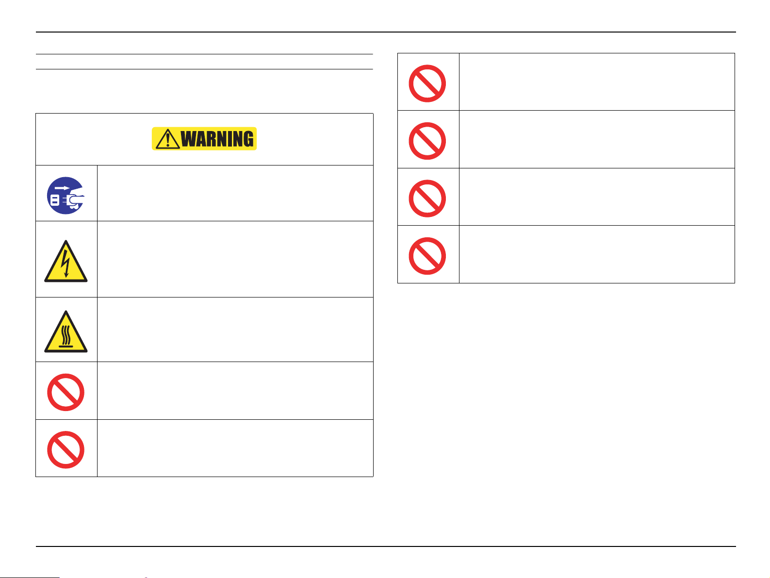
SAFETY INSTRUCTIONS
The precautionary measures itemized below should be fully understood when
performing repair and maintenance procedures.
When disassembling/assembling, be sure to turn off the power
switch and pull out the power cable from the projector beforehand.
Never touch the current-carrying part or high temperature section
during a test operation, signal measurement or any other situations
that is necessary to perform the repair/maintenance work with the
power turned on and the cover removed.
Do not wear the metal products such as wrist watch, cuff buttons,
rings, tiepin etc. to avoid getting a electric shock.
Do not touch the lamp assy. or the parts around it. They are
extremely hot even after completed the cooling down operation, and
may cause a burn injury.
Therefore, leave the unit until it becomes cool enough before
performing maintenance work.
Never modify the product for any reason whatsoever.
(Except for a case that is under the instructions to do so.)
Never peer through the projection lens during repair/maintenance
work when the power is on.
(Such an action may cause a visual disability because of a very
strong light emission.)
Never use a deformed plug or a damaged power cable to this
product.
If any deformations or damages are found on the power cable or
plug section, replace it with a new specified power cable.
Never use the air blowers that contain flammable gas in repair/
maintenance work.
Never let the safety devices mounted in this product inactivated for
any reason whatsoever.
Never modify the safety devices or replace them with the ones that
are not designated for any reason whatsoever.
(Such actions may cause a fire or serious injury.)
SEIKO EPSON 5 Revision C
Page 6
EB-S01/W01/X14G/S11/X11/S0 2/S02H/X02/W02/S12/S12H /X 1 2/ W 12 /X1 4 EH- TW 4 8 0
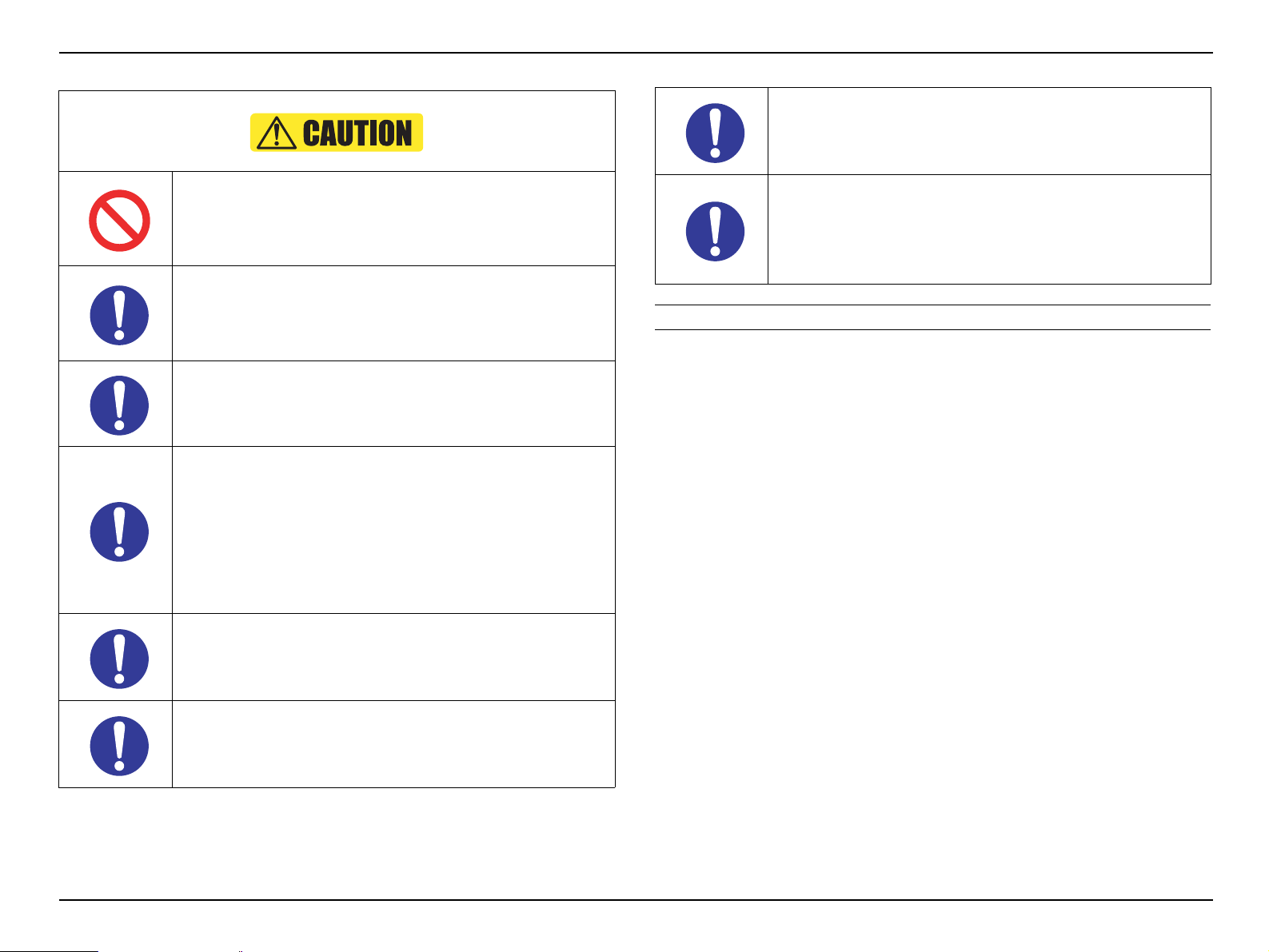
Never use or replace with any service parts that is not specified by
EPSON.
Be sure to perform the repair/maintenance work on the even and
stable work bench to prevent the product from dropping down or
mal-operation due to the improper setting of the product.
Be sure to wear the gloves during the repair/maintenance work to
avoid injuries by the parts with sharp edges such as metal plate or
the like.
To protect sensitive circuitry, follow the instructions below.
When disassembling or reassembling, be sure to wear static
discharge equipment such as an anti-static wrist strap and a
mat.
When replacing the circuit component such as a board or the
optical engine, be sure to get in contact with the anti-static
case containing the new one to the metal part of this product
before taking it out.
CONFIDENTIAL
Be careful not to drop a metal part such as a screw, a washer, or a
clip into the inside of the product. If such cases should occur
accidentally, never turn on the power supply until all the dropped
parts are found and removed.
After reassembling the product, check the followings before
turning the power on.
All the parts and screws are installed and secured to the
proper positions.
No cables are caught in the metal frames.
OTHER CAUTION
Since the lamp of this product contains mercury, be sure to dispose the used lamp
pursuant to the government’s law and regulations.
When performing the repair/maintenance work, be sure to use the
specified tools and follow the instructions that are specified in the
documents (service manual etc.) concerning to this product.
When carrying out the test operation, do not block the intake and
exhaust ducts.
(Such an action raises the internal temperature and may cause a
fire or a damages to the internal parts of this product.)
SEIKO EPSON 6 Revision C
Page 7
EB-S01/W01/X14G/S11/X11/S0 2/S02H/X02/W02/S12/S12H /X 1 2/ W 12 /X1 4 EH- TW 4 8 0
CONFIDENTIAL
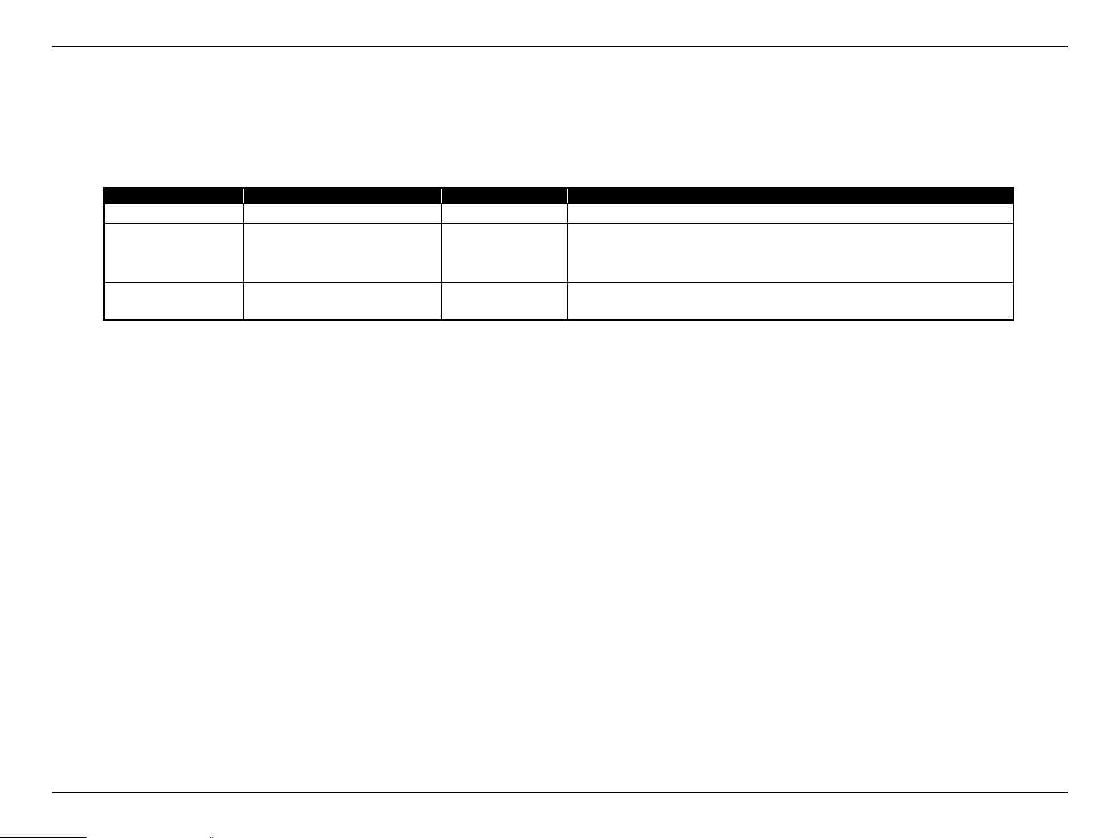
REVISION HISTORY
After first release of this manual, the parts and mechanism may be subject to change for improvement of their performance and the manual may be revised. Be sure
to always keep this manual up to date.
Revision Date Page of change Detail of change
A 2011.6.15 all First Release
B 2011.8.5 P.75
P.78
P.131
C 2012.5.28 all Addition of models.
Change of caution.
Addition of caution.
Addition of caution.
Full-fledged revision
SEIKO EPSON 7 Revision C
Page 8

EB-S01/W01/X14G/S11/X11/S0 2/S02H/X02/W02/S12/S12H /X 1 2/ W 12 /X1 4 EH- TW 4 8 0
CONFIDENTIAL
Contents
Chapter 1 Product Description
1.1 Model Name......................................................................................................... 11
1.2 Features........................................ ......................................................................... 12
1.3
Specifications ........................................................................................... 13
1.4 Dimensions............................................................................................... 15
1.5 Ceiling Mount................................................................... ........................ 17
Chapter 2 Troubleshooting
2.1 Required Tools ..................................................................................................... 22
2.2 Troubleshooting Procedure .................................................................................. 22
2.3 Exterior Check...................................................................................................... 23
2.3.1 Parts Layout Diagrams ................................................................................ 23
2.4 Error Indication and Problem diagnosis............................................................... 29
2.4.1 LED Indication ............................................................................................ 29
2.4.2 Troubleshooting based on LED Indications ............................................. ... 31
2.4.3 Troubleshooting from the Error Codes........................................................ 33
2.4.4 Troubleshooting without Error Indications ......... ..................................... ... 38
2.4.5 Troubleshooting on image abnormality........................... ............................ 44
2.4.6 Cable Connection and Projector’s Status .................................................... 46
2.5 Operation and Safety Check after repair .............................................................. 49
2.5.1 Each Operation Check................................................................................. 49
Chapter 3 Disassembly and Assembly
3.1 Precautions ........................................................................................................... 53
3.1.1 General Cautions in operation.................................... ................................. 53
3.1.2 Precautions................................................................................................... 54
3.1.3 Workflow ..................................................................................................... 54
3.1.4 Standard Operation Time............................................................................. 55
3.1.5 Tools............................................................................................................ 55
3.2 Flowchart.............................................................................................................. 56
3.3 Disassembly.......................................................................................................... 59
3.3.1 Air Filter........................................... ..................................... ...................... 59
3.3.2 Lamp............................................................................................................ 60
3.3.3 Rear Foot ..................................................................................................... 61
3.3.4 Front Foot.................................................................................................... 62
3.3.5 Upper Case (assembly)................................................................................ 62
3.3.5.1 SW Board............................................................................................ 67
3.3.5.2 HK Assy (EB-X11/S12/S12H/X12/W12/X14 EH-TW480 only) ...... 69
3.3.5.3 Shutter Switch............................................................... ...................... 70
3.3.5.4 Upper Case.......................................................................................... 72
3.3.6 MA Board (assembly) ................................................................................. 74
3.3.6.1 IF Case.................................. .............................................................. 78
3.3.6.2 MA Board / RS Board (EB-S11/X11 only)........................................ 79
3.3.7 Speaker ........................................................................................................ 81
3.3.8 Optical Engine............................................................................................. 82
3.3.8.1 Auto Iris.............................................................................................. 83
3.3.8.2 Focus Ring / Zoom Ring..................................................................... 85
3.3.9 Lamp Fan..................................................................................................... 86
3.3.10 EX Duct (assembly)................................................................................... 87
3.3.10.1 TH Board (2) / EX Fan..................................................................... 88
3.3.11 BA Power Supply (assembly).................................................................... 89
3.3.11.1 BA Unit / SCI Cable......................................................................... 93
3.3.11.2 PS Filter ............................................................................................ 94
SEIKO EPSON 8 Revision C
Page 9

EB-S01/W01/X14G/S11/X11/S0 2/S02H/X02/W02/S12/S12H /X 1 2/ W 12 /X1 4 EH- TW 4 8 0
CONFIDENTIAL
3.3.12 INT Duct (assembly) ............................................................. .................... 96
3.3.12.1 IR Board............................................................................................ 97
3.3.12.2 INT Fan / TH Board (1).................................................................... 99
3.3.13 Lower Case.............................................................................................. 101
3.4 Safety Check after Servicing.............................................................................. 103
3.5 Writing the DR Data........................................................ ................................... 106
3.5.1 Overview.................................................................................................... 106
3.5.2 Preparation................................................................................................. 107
3.5.3 Operating Procedure.................................................................................. 107
3.5.3.1 Workflow.......................................................................................... 107
3.5.3.2 Check in advance.............................................................................. 108
3.5.3.3 Replacing the Optical Engine ........................................................... 110
3.5.3.4 Replacing the MA Board .................................................................. 112
3.6 Reference (Part Names given in the SPI)........................................................... 116
Chapter 4 Maintenance
4.1 Precautions ......................................................................................................... 119
4.1.1 General Cautions in operation.................................... ............................... 119
4.1.2 Tools............................. ............................................................................. 120
4.2 Replacing the Internal Parts/Components of Optical Engine............................. 121
4.2.1 N POLARIZER UNIT;B/R.......................................... ............................. 122
4.2.2 CONDENSER LENS;D/FB/FG2/R.......................................................... 125
4.2.3 BDM/GDM................................................................................................ 129
4.2.4 MIRROR;R................................................................................................ 131
4.2.5 PBS MASK ASSY.2 ................................................................................. 133
4.2.6 MULTI LENS;A........................................................................................ 135
Chapter 5 Appendix
5.1 AS (After Service) Menu ................................................................................... 139
5.1.1 How To Display the AS (After Service) Menu......................................... 139
5.1.2 Displaying the Pages ................................... ..................................... ......... 139
5.1.3 Initializing (Resetting) the AS Menu Values ............................................ 142
SEIKO EPSON 9 Revision C
Page 10

PRODUCT DESCRIPTION
CHAPTER
1
CONFIDENTIAL
Page 11
EB-S01/W01/X14G/S11/X11/S0 2/S02H/X02/W02/S12/S12H /X 1 2/ W 12 /X1 4 EH- TW 4 8 0
Product Description CONFIDENTIAL
1.1 Model Name
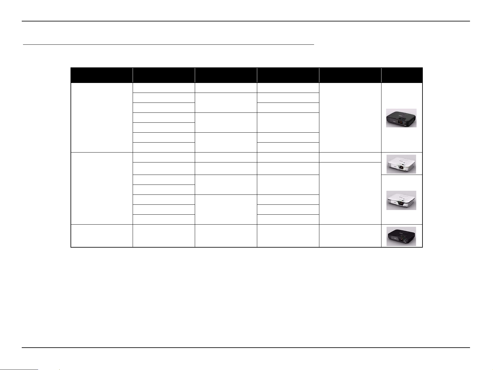
EB-S01/W01/X14G/S11/X11/S02/S02H/X02/W02/S12/S12H/X12/W12/X1 4 EH-TW480 are divided into three groups by their mechanical differences. The classified model
names are provided below.
Type Model Name
Business Type A
Optical Zoom
(Manual)
EB-S01 N/A SVGA
EB-W01
EB-X14G XGA
EB-S02
EB-S02H
EB-X02
EB-W02 WXGA
EB-S11 N/A SVGA N/A
3
N/A SVGA
3
Native
resolution
WXGA
XGA
Horizontal Keystone
Correction
N/A
External View
EB-X11
EB-S12
Business Type B
Home Type EH-TW480
EB-S12H
EB-X12
EB-W12 WXGA
EB-X14 XGA
3 XGA
N/A SVGA
3
XGA
3
3 WXGA 3
SEIKO EPSON 11 Revision C
Page 12
EB-S01/W01/X14G/S11/X11/S0 2/S02H/X02/W02/S12/S12H /X 1 2/ W 12 /X1 4 EH- TW 4 8 0
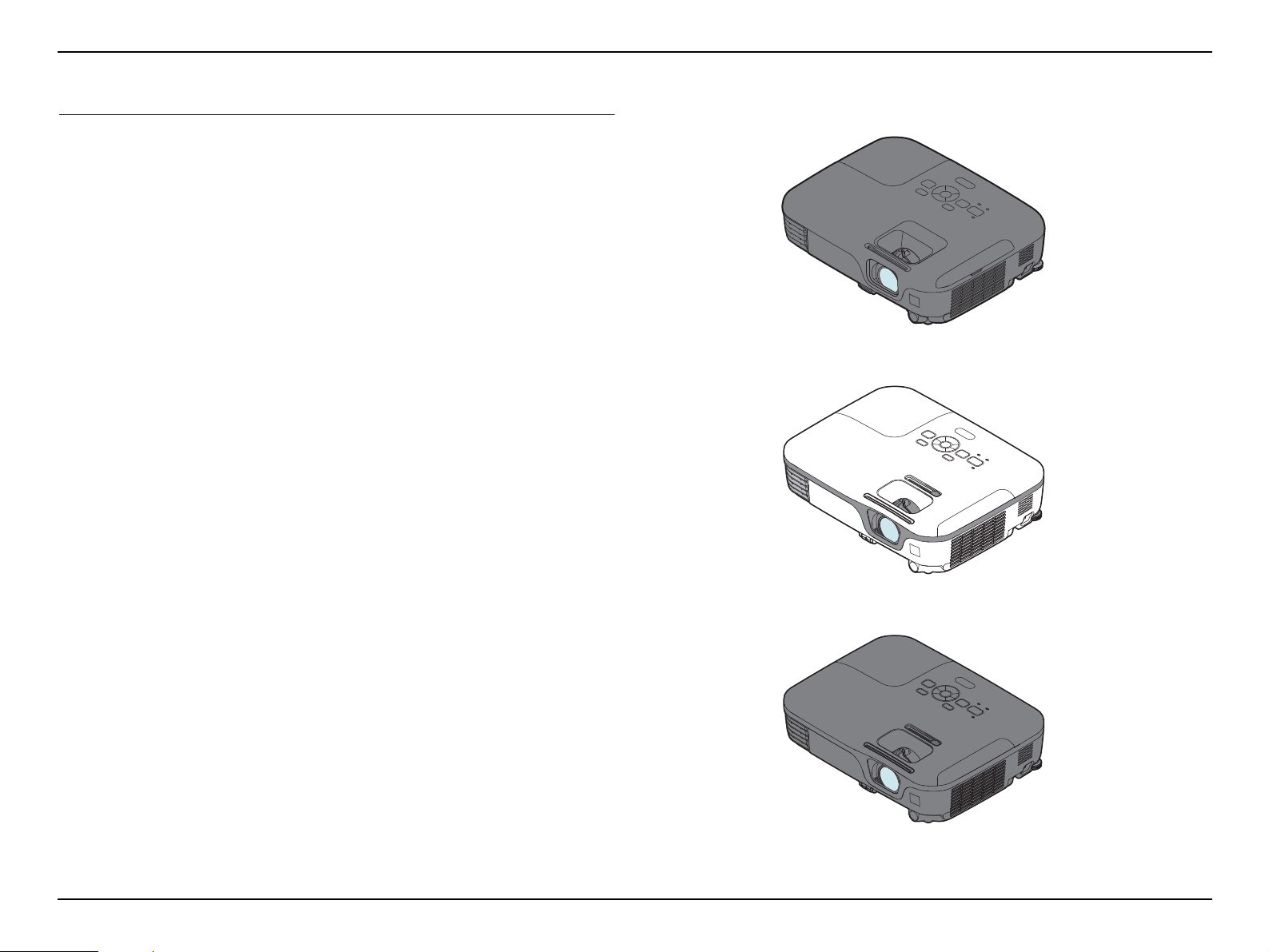
Business Type B: EB-S11/X11/S12/S12H/X12/W12/X14
Business Type A: EB-S01/W01/X14G/S02/S0 2H/X02/W02
Home Type: EH-TW480
Product Description CONFIDENTIAL
1.2 Features
The EB-S01/W01/X14G/S11/X11/S02/S02H/X02/W02/S12/S12H/X12/W12/X14
EH-TW480 are portable compact business/home projectors with the following
features:
Auto Vertical-Keystone
(EB-X14G/X11/S02/S02H/X02/W02/S12/S12H/X12/W12/X14 EH-TW480
only)
When the sensor of the projector detects the change in setting, the projector
automatically corrects the keystone in the vertical direction.
Horizontal Keystone Adjuster
(EB-X11/S12/S12H/X12/W12/X14 EH-TW480 only)
This allows you to quickly correct horizontal distortion of the projected image.
Direct Power On/Off
No cool-down period is needed.
Project screen for WXGA (16:10)
(EB-W01/W02/W12 EH-TW480 only)
Auto Iris
With an optional document camera (ELPDC06/ELPDC11), you can magnify and
project the images of your documents.
USB connection for projection (USB Display) is available.
USB term inal (Type B) for USB Display
Slide show is available
(EB-S11/X11/S12/S12H/X12/W12/X14 EH-TW480 only)
The images in a USB flash drive can be projected without using a computer
USB terminal (Type A) for USB Display
HDMI terminals
(EB-S02H/S12H/X12/W12/X14 EH-TW480 only)
Enhanced security functions
Password protection
Operation Lock
Anti-theft Lock
Figure 1-1. External View
SEIKO EPSON 12 Revision C
Page 13
EB-S01/W01/X14G/S11/X11/S0 2/S02H/X02/W02/S12/S12H /X 1 2/ W 12 /X1 4 EH- TW 4 8 0
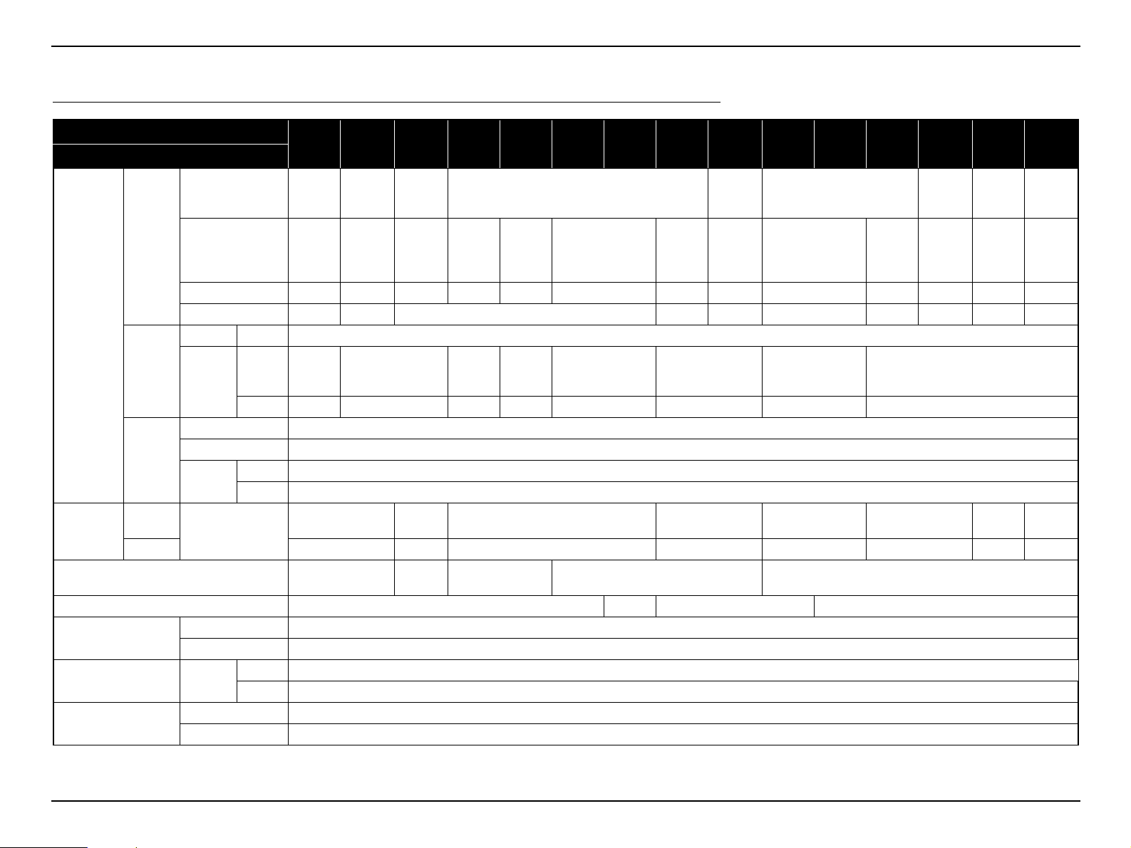
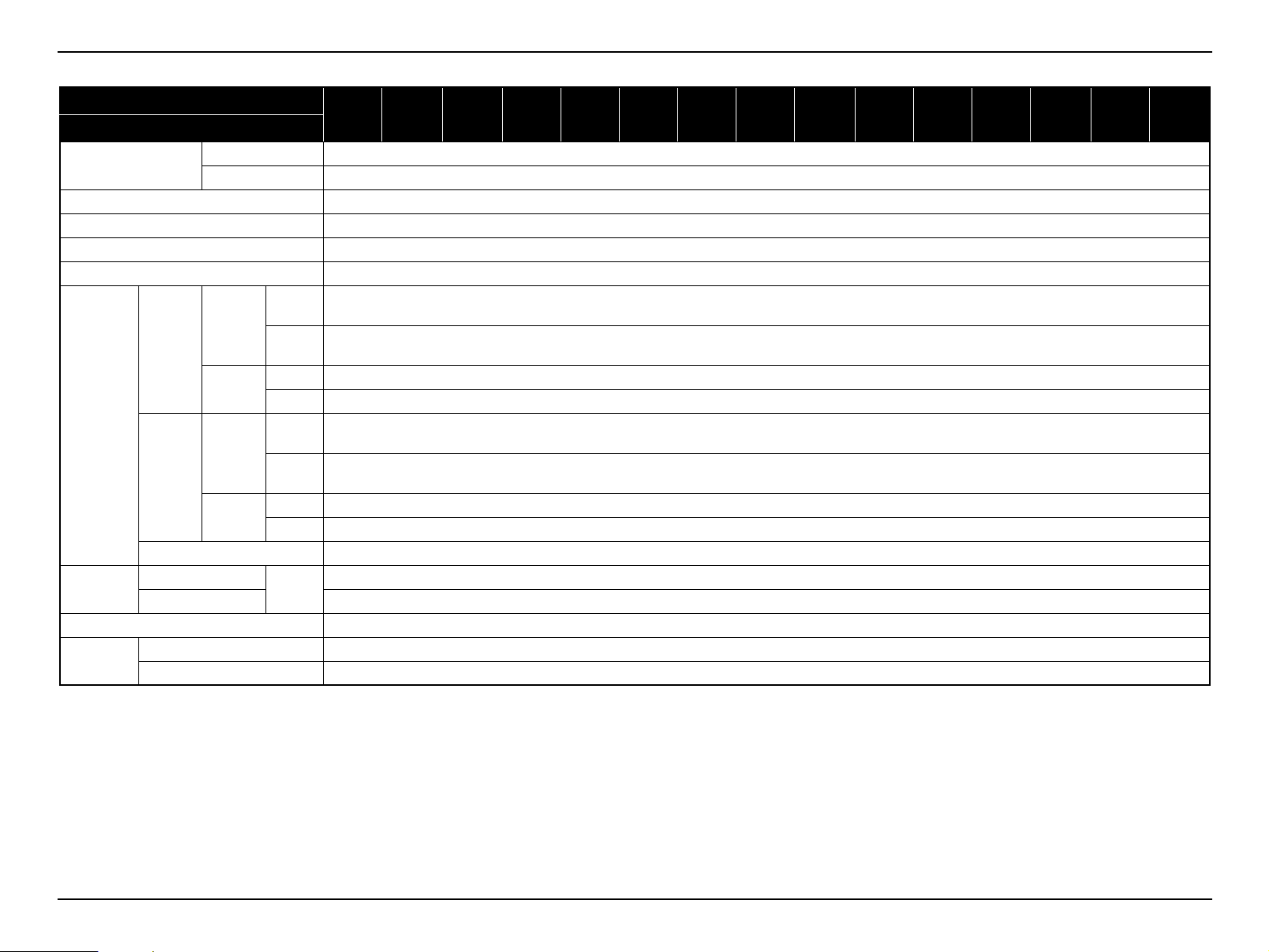
1.3 Specifications
Product Description CONFIDENTIAL
Model
Item
Size
LCD
Specification
of main part
Projection
Lens
Lamp
Normal
Brightness
Sound output 2 W x 1 Monaural
HDMI terminal N/A x 1 N/A x 1
Network Function
USB terminal USB I/O
Operating Temperature
mode
Eco mode 2080 lm 2400 lm 2080 lm 2080 lm 2240 lm 2240 lm 2400 lm 2240 lm
Pixel number
Native resolution SVGA WXGA XGA SVGA XGA SVGA XGA WXGA SVGA XGA WXGA XGA WXGA
Aspect ratio 4:3 16:10 4:3 4:3 16:10 4:3 4:3 16:10 4:3 16:10
Focus Type Manual focus
Zoom
Type UHE (E-TORL)
Power consumption 200 W
Life
Color mode:
Dynamic,
Zoom: Wide
Wired LAN N/A
Wireless LAN Unit N/A
Temperature 5°C to 35°C
Humidity 20% to 80%
Type
Ratio 1.0 - 1.35 1.0 - 1.2 1.0 - 1.35 1.0 - 1.2 1.0 - 1.35 1.0 - 1.2 1.0 - 1.35 1.0 - 1.2
Normal
Eco 5000 H
Type A x 1 (S02 is excluded)
Type B x 1
EBS01
0.55 inch
(without
MLA)
480,000
dots
(800 x
600) x 3
Digital
Zoom
EB-
W01
0.59 inch
(with
MLA)
1,024,000
dots
(1280 x
800) x 3
Manual optical zoom
2600 lm 3000 lm 2600 lm 2600 lm 2800 lm 2800 lm 3000 lm 2800 lm
EB-
X14G
0.55 inch
(with
MLA)
786,432
dots
(1024 x
768) x 3
1 W x 1
Monaural
EBS11
480,000
dots
(800 x
600) x 3
Digital
Zoom
2 W x 1 Monaural 1 W x 1 Monaural 2 W x 1 Monaural
EBX11
0.55 inch (without MLA)
786,432
dots
(1024 x
768) x 3
Manual
optical
zoom
EBS02
480,000 dots
(800 x 600) x 3
Digital Zoom Manual optical zoom Digital Zoom Manual optical zoom
EB-
S02H
EBX02
786,432
dots
(1024 x
768) x 3
4000 H
EB-
W02
0.59 inch
(with
MLA)
1,024,000
dots
(1280 x
800) x 3
EBS12
480,000 dots
(800 x 600) x 3
EB-
S12H
0.55 inch
(without MLA)
EBX12
786,432
dots
(1024 x
768) x 3
EB-
W12
0.59 inch
(with
MLA)
1,024,000
dots
(1280 x
800) x 3
EBX14
0.55 inch
(with
MLA)
786,432
dots
(1024 x
768) x 3
EH-
TW480
0.59 inch
(with
MLA)
1,024,000
dots
(1280 x
800) x 3
SEIKO EPSON 13 Revision C
Page 14
EB-S01/W01/X14G/S11/X11/S0 2/S02H/X02/W02/S12/S12H /X 1 2/ W 12 /X1 4 EH- TW 4 8 0
Product Description CONFIDENTIAL
Model
Item
Operating Altitude
Start-up period 5 seconds
Warm-up period 30 seconds
Cool-down period Instant off
Power supply voltage 100 - 240 V AC
100-120V
Area
(JAPAN,
USA,etc.)
Power
Consumption
220-240V
Area
(Europe,
etc.)
Rated Voltage & Current 100 - 240 V AC 50/60 Hz 2.9 - 1.3 A
Size
Weight Approx. 2.3 kg/5.1 lbs
Fan noise
Excluding feet
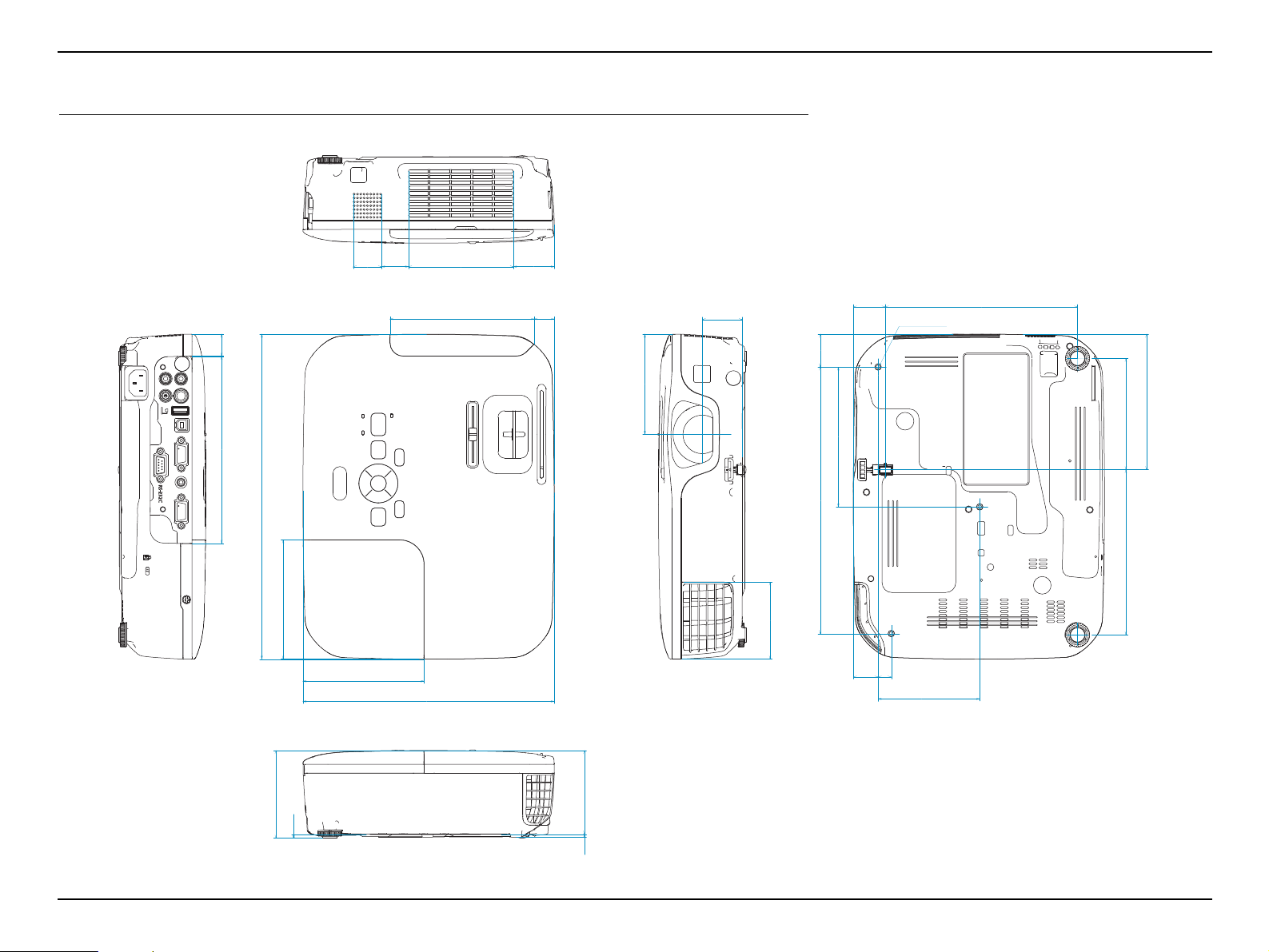
Maximum Dimension 228 (D) x 295 (W) x 79 (H)
Normal mode 37 dB
Eco mode 29 dB
Normal 0 m to 2286 m <0 ft to 7500 ft>
High altitude mode Over 1500 m / 4,921 ft
ON
Lamp
Standby
(Network)
Lamp
Standby
(Network)
(Normal)
ON
(Eco)
ON 2.9 W
OFF 0.36 W
ON
(Normal)
ON
(Eco)
ON 3.3 W
OFF 0.47 W
Unit:
mm
EBS01
EB-
W01
EB-
X14G
EBS11
EBX11
EBS02
EB-
S02H
EBX02
W02
± 10%, 50/60 Hz
283 W
234 W
270 W
223 W
228 (D) x 295 (W) x 77 (H)
EB-
EBS12
EB-
S12H
EBX12
EB-
W12
EBX14
EH-
TW480
SEIKO EPSON 14 Revision C
Page 15
EB-S01/W01/X14G/S11/X11/S0 2/S02H/X02/W02/S12/S12H /X 1 2/ W 12 /X1 4 EH- TW 4 8 0
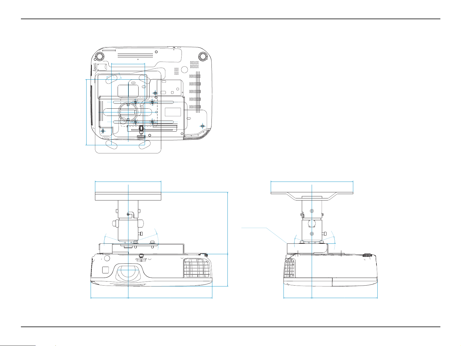
3XM4 9mm
20
2.6
3.5
91
3724.4
101
123
70
95.2
29.8
18.2130.8
36.3
76
174.5
25.8
79.5
29
242
127
22.5
92.3
12
108.3
150
110
228
295
169.8
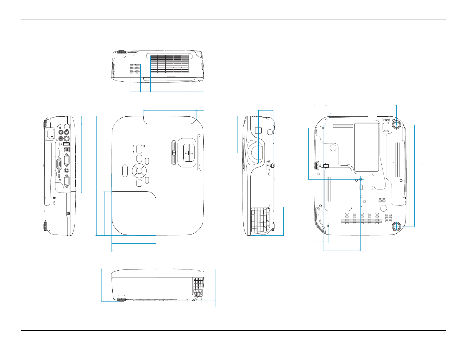
Unit: mm
1.4 Dimensions
Product Description CONFIDENTIAL
SEIKO EPSON 15 Revision C
Page 16
EB-S01/W01/X14G/S11/X11/S0 2/S02H/X02/W02/S12/S12H /X 1 2/ W 12 /X1 4 EH- TW 4 8 0
3XM4 9mm
0.8
0.1
0.1
3.6
1.50.96
3.98
4.84
2.8
3.75
1.17
0.725.15
1.43
3.0
6.87
1.02
3.13
1.1
9.53
5.00
0.89
3.63
0.5
4.26
5.91
4.33
8.98
11.6
6.69
Unit: inch
Product Description CONFIDENTIAL
SEIKO EPSON 16 Revision C
Page 17
EB-S01/W01/X14G/S11/X11/S0 2/S02H/X02/W02/S12/S12H /X 1 2/ W 12 /X1 4 EH- TW 4 8 0
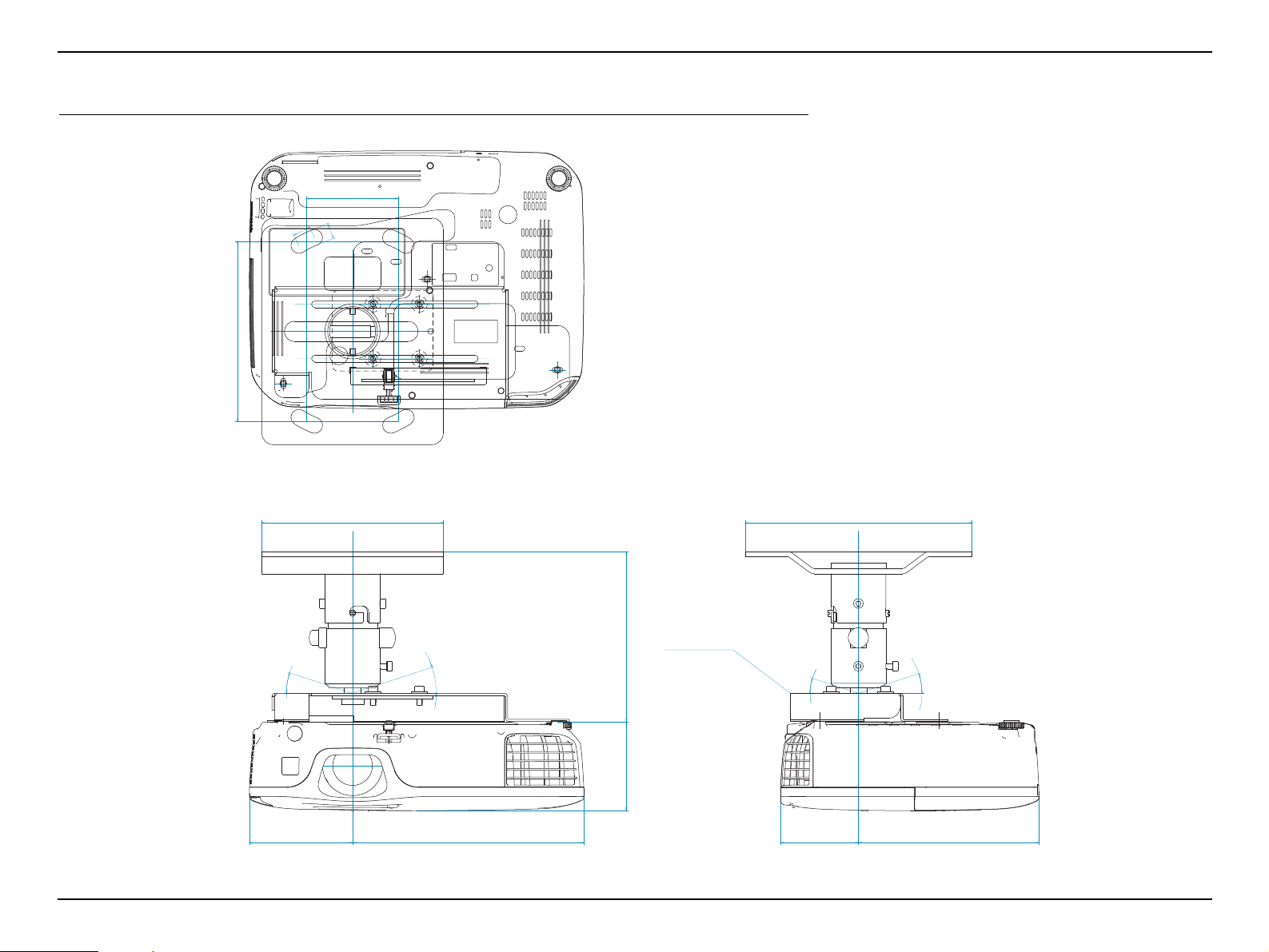
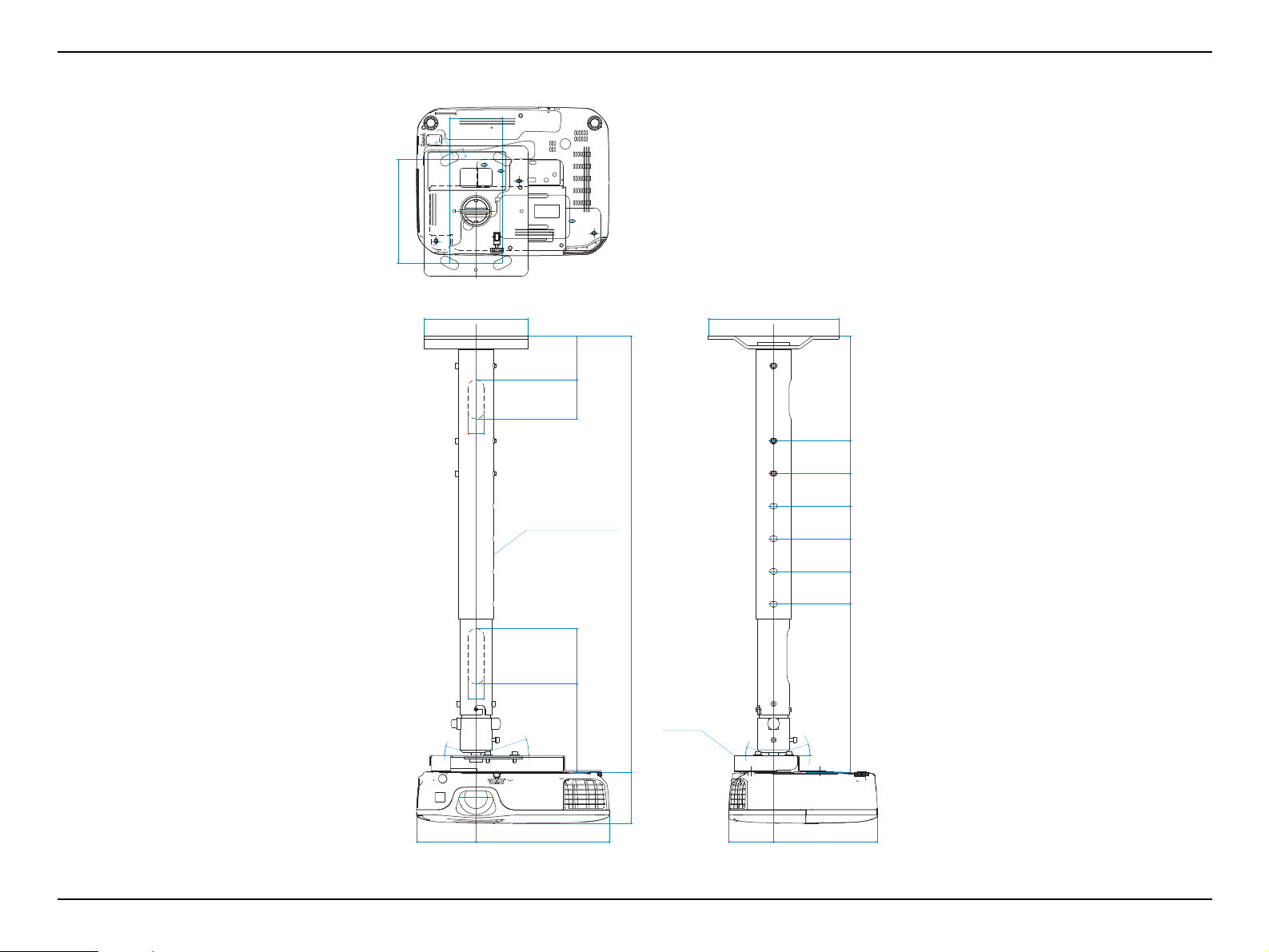
Unit: mm
1.5 Ceiling Mount
81
14
16
159
Product Description CONFIDENTIAL
18°
160
18°
150
ELPMB23
18°
200
18°
79
20491
68
SEIKO EPSON 17 Revision C
159
Page 18
EB-S01/W01/X14G/S11/X11/S0 2/S02H/X02/W02/S12/S12H /X 1 2/ W 12 /X1 4 EH- TW 4 8 0
Unit: inch
3.2
0.6
0.6
6.26
Product Description CONFIDENTIAL
18°
6.30
18°
5.91
ELPMB23
18°
7.87
18°
3.1
8.033.6
2.7
SEIKO EPSON 18 Revision C
6.26
Page 19

EB-S01/W01/X14G/S11/X11/S0 2/S02H/X02/W02/S12/S12H /X 1 2/ W 12 /X1 4 EH- TW 4 8 0
Unit: mm
81
16
14
159
Product Description CONFIDENTIAL
160
25
ELPFP13: 668-918mm
ELPFP14: 918-1168mm
668
25
135 85 60 67
18°
18°
ELPMB23
200
161
50257
50505050
18°
18°
79
91 204
15968
SEIKO EPSON 19 Revision C
Page 20
EB-S01/W01/X14G/S11/X11/S0 2/S02H/X02/W02/S12/S12H /X 1 2/ W 12 /X1 4 EH- TW 4 8 0
Unit: inch
3.2
0.6
0.6
6.26
Product Description CONFIDENTIAL
6.30
1.0
ELPFP13: 26.3-36.1inch
ELPFP14: 36.1-46.0inch
26.3
1.0
5.31 3.3 2.4 2.6
18°
18°
ELPMB23
7.87
6.34
2.010.1
2.02.02.02.0
18°
18°
3.1
3.6 8.03
6.262.7
SEIKO EPSON 20 Revision C
Page 21

TROUBLESHOOTING
CHAPTER
2
CONFIDENTIAL
Page 22
EB-S01/W01/X14G/S11/X11/S0 2/S02H/X02/W02/S12/S12H /X 1 2/ W 12 /X1 4 EH- TW 4 8 0
Check the parts to be repaired visually.
(See “ 2.3 Exterior Check (p23)”.)
Problem diagnosis and troubleshooting
If LED error indication is indicated,
=> See “ 2.4.2 Troubleshooting based on LED Indications (p31)”.
If you know the error code
=> See “ 2.4.3 Troubleshooting from the Error Codes (p33)”.
If abnormality related to the projector’s performance is occurring,
=> See “ 2.4.4 Troubleshooting without Error Indications (p38)”.
If image quality is abnormal,
=> See “ 2.4.5 Troubleshooting on image abnormality (p44)”.
Reassembly, operation check and Safety check*
*In the case that a safety device (p.103) is repaired
or maintained.
Start
Troubleshooting CONFIDENTIAL
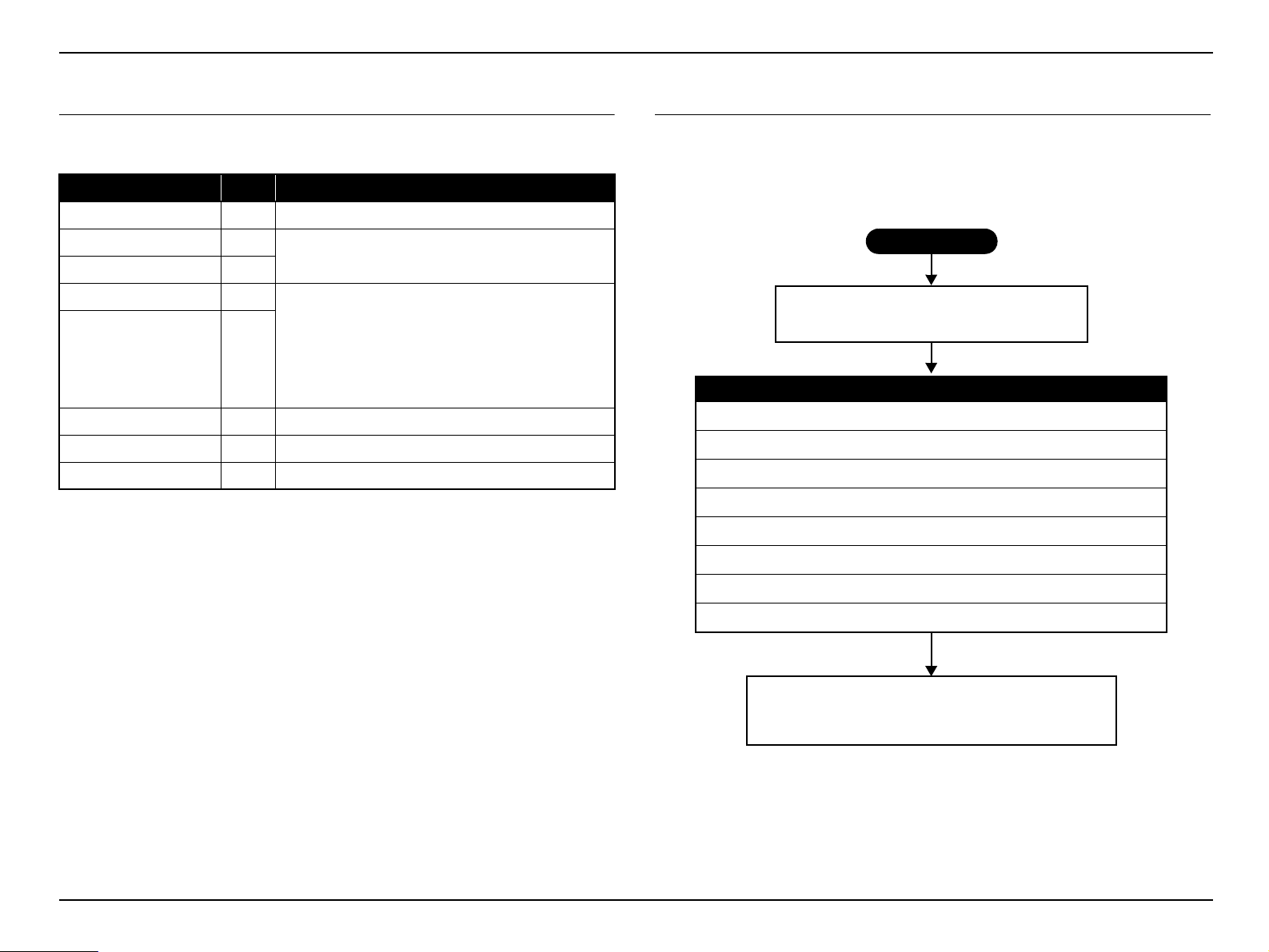
2.1 Required Tools
The following tools and equipment will be required in order to carry out
troubleshooting, and so you should check that they are on hand.
Name Qt. Application/Other
Projection screen 1 To project image on
Host computer 1
PC cable 1
Video equipment 1
Audio and Video cables
(HDMI/S-video/
Composite/USB,
and audio for those listed
above)
Multi meter 1 To measure resistance values and voltages (AC/DC)
Double-sided tape q.s. To secure parts
General tools 1set Tools given in “ 3.1.5 Tools (p55)”
Note 1: q.s.: Sufficient quantity
2: When repairing an EB-W01/W02/W12/EH-TW480 (16:10 wide panel model), prepare
your video source and device considering the full screen display of 16:10 aspect.
To output audio and video data to the projector
(To check the component video input)
To transfer audio and video data to the projector
(To check the HDMI, S-Video, composite video, USB
1
input)
each
2.2 Troubleshooting Procedure
This chapter describes troubleshooting procedure starting from error messages/status to
diagnose problems. Refer to the descriptions and remedies below to specify the
troubled part, and carry out the necessary repair or replacement.
Figure 2-1. Troubleshooting Workflow
SEIKO EPSON 22 Revision C
Page 23
EB-S01/W01/X14G/S11/X11/S0 2/S02H/X02/W02/S12/S12H /X 1 2/ W 12 /X1 4 EH- TW 4 8 0
Troubleshooting CONFIDENTIAL
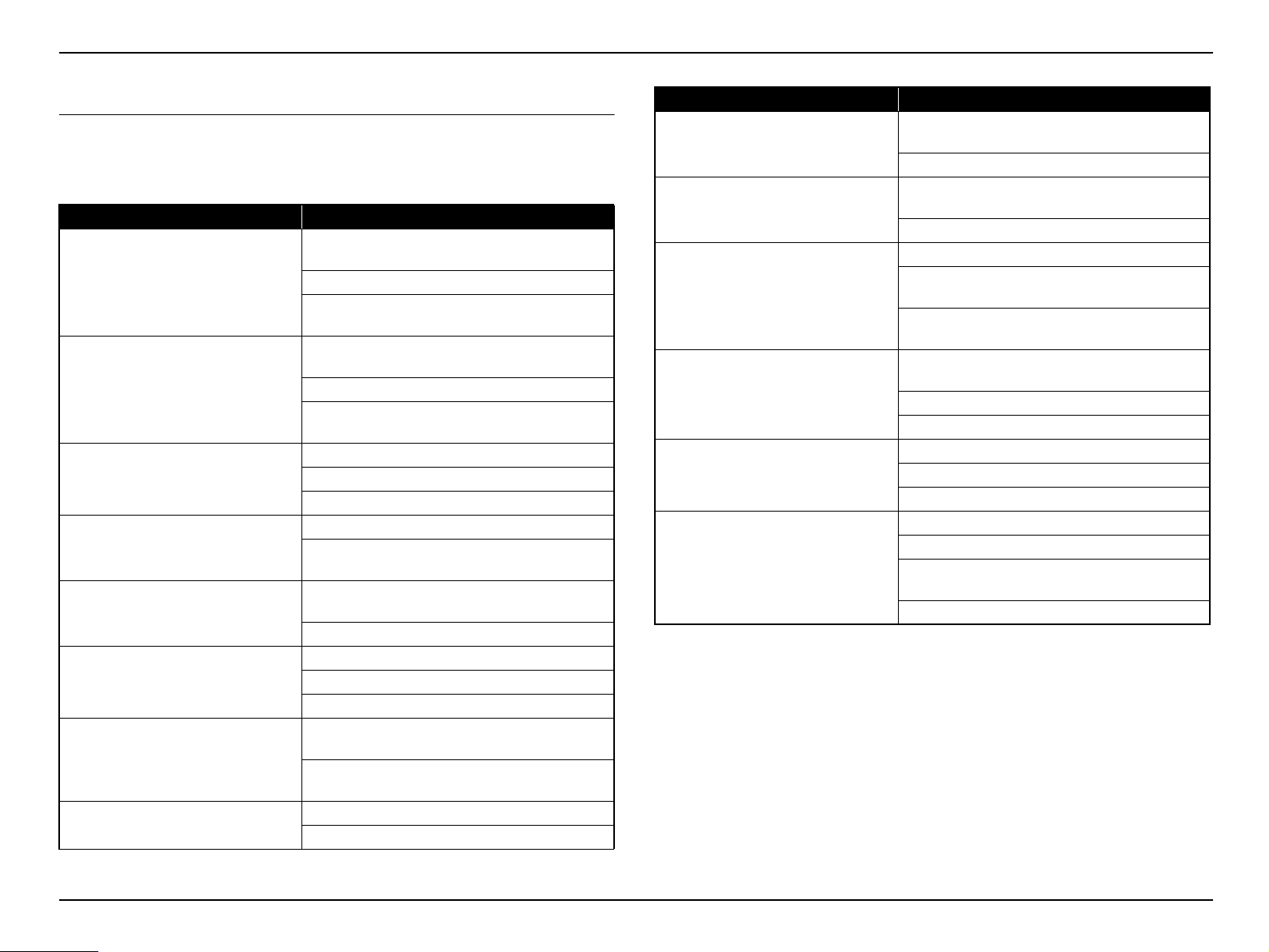
2.3 Exterior Check
When repairing this product, carry out exterior check of the target parts/units as
necessary.
Check Items
Target part Check item
Any damage/deformation/cracking due to external
forces?
Upper Case
IF Case
SW Board
Lamp Cover
Air Filter Cover
Projection Lens
Lower Case
Foot
Is it fixed to the Lower Case correctly?
Any foreign object/dirt on the IR receivers (Front
and Rear)?
Any damage/deformation/cracking due to external
forces?
Is it fixed with screws correctly?
Is it fixed to the Lower Case and Upper Case
correctly?
Is it fixed to Upper Case correctly?
Any stuck buttons?
Does Buttons work smoothly?
Is it fixed to Upper Case correctly?
Any damage on the latch to operate the Interlock
Switch? (Check for it with the cover removed.)
Any damage/deformation/cracking due to external
forces?
Is it fixed to the Upper Case correctly?
Does Focus Ring work smoothly?
Does Zoom Ring work smoothly?
Any dirt/scratches on the projection lens?
Any damage/deformation/cracking due to external
forces?
Any foreign object/dirt on the filter cover or the
vents?
Does Front Foot work smoothly to adjust height?
Any Foot Rubber detached?
Target part Check item
Any deformation/discoloration on the connector/
AC Inlet
Interfaces
Air Filter
HK Assy
Lens Shutter
Lamp
terminals?
Any damage on the socket?
Any deformation/discoloration on the connector/
terminals?
Any foreign objects on the connectors/terminals?
Is it fixed correctly?
Any dirt on the filter? (check for it with the filter
removed.)
Any dirt/foreign materials on the fan inside the
filter?
Any damage/deformation/cracking due to external
forces?
Is it fixed to Upper Case correctly?
Does it work smoothly?
Any deformation/discoloration on it?
Is it fixed to Upper Case correctly?
Does it work smoothly?
Any deformation/discoloration on the frame?
Any deformation/discoloration on the connector?
Are the screws that secure the Lamp tightened
securely?
Any dirt on the glass surface?
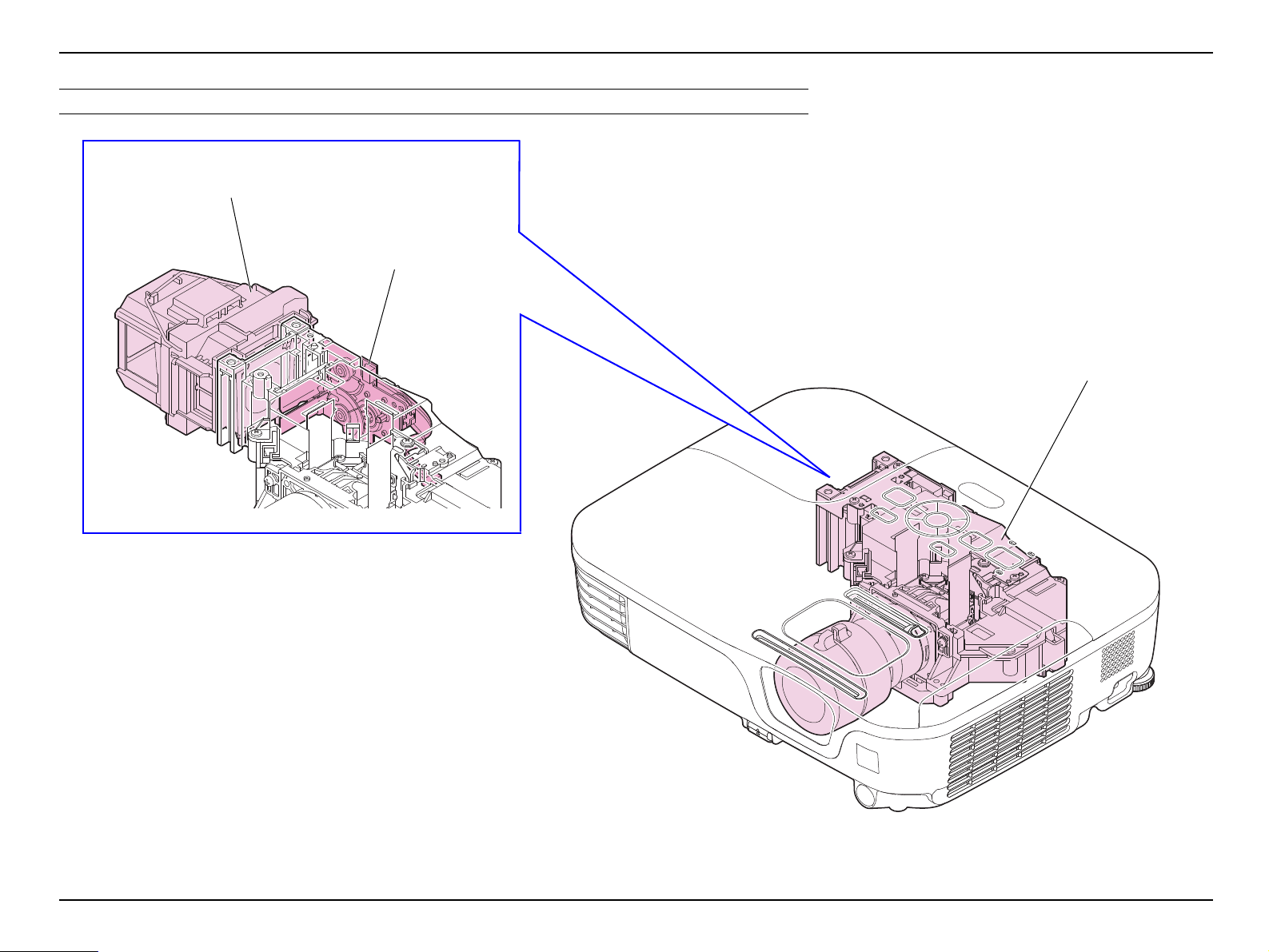
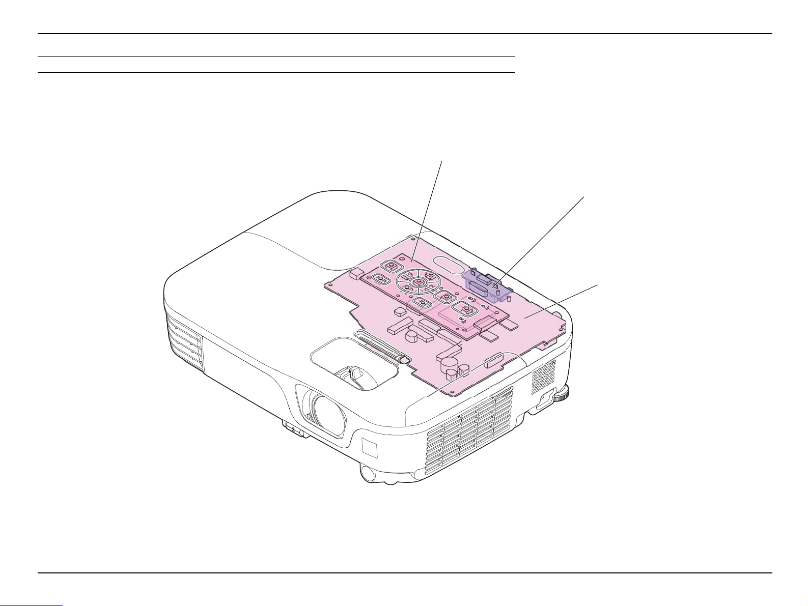
2.3.1 Parts Layout Diagrams
The following are the diagrams to confirm and locate the parts and/or components to be
repaired. The parts names used here indicate the references linked to the page titles for
their disassembling procedures.
SEIKO EPSON 23 Revision C
Page 24
EB-S01/W01/X14G/S11/X11/S0 2/S02H/X02/W02/S12/S12H /X 1 2/ W 12 /X1 4 EH- TW 4 8 0
Optical Engine (p82)
Auto Iris (p83)
Lamp (p60)
OPTICAL PARTS
Troubleshooting CONFIDENTIAL
Figure 2-2.
SEIKO EPSON 24 Revision C
Page 25
EB-S01/W01/X14G/S11/X11/S0 2/S02H/X02/W02/S12/S12H /X 1 2/ W 12 /X1 4 EH- TW 4 8 0
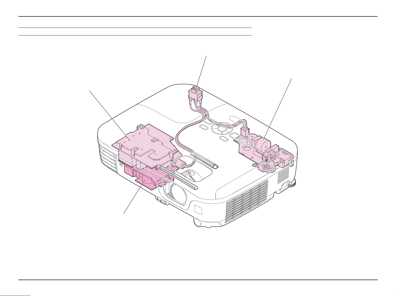
PS Filter (p94)
BA Unit (p.93)
Filter Board (PS Filter (p94))
Interlock Switch (PS Filter (p94))
POWER SUPPLY
Troubleshooting CONFIDENTIAL
Figure 2-3.
SEIKO EPSON 25 Revision C
Page 26
EB-S01/W01/X14G/S11/X11/S0 2/S02H/X02/W02/S12/S12H /X 1 2/ W 12 /X1 4 EH- TW 4 8 0
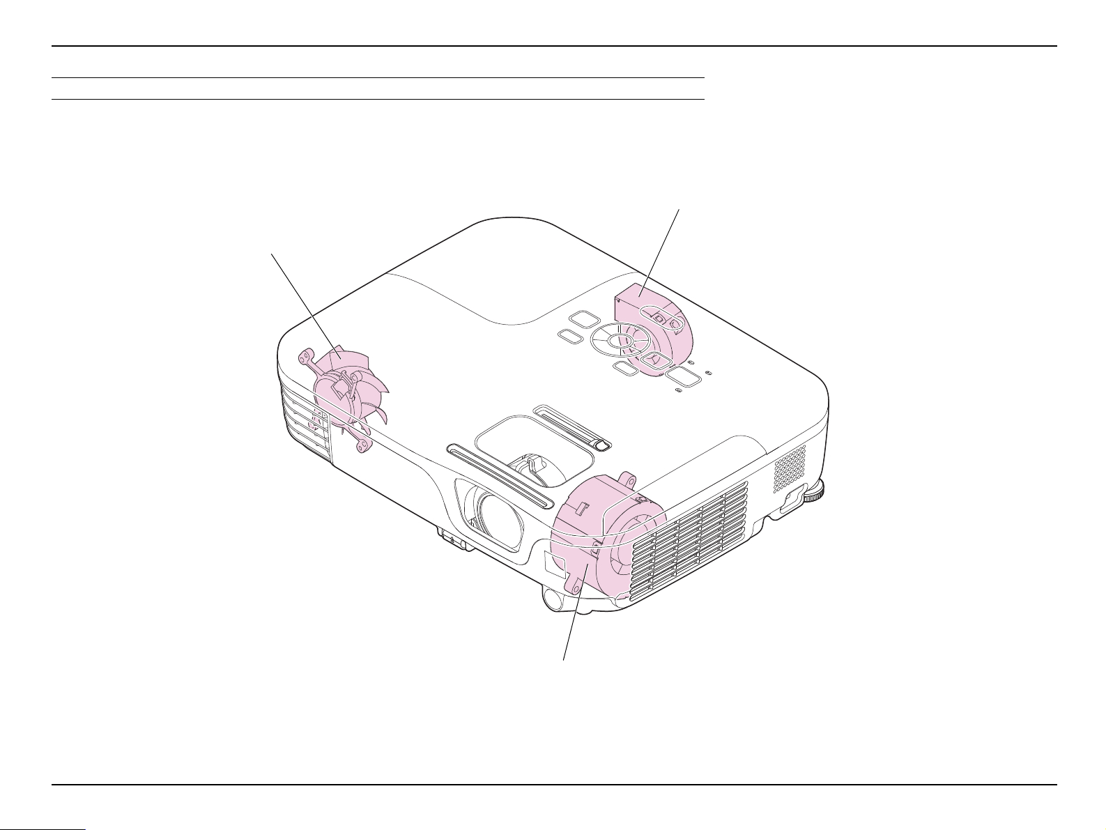
INT Fan / TH Board
(1) (p99)
Lamp Fan (p86)
EX Fan (p.88)
COOLING SYSTEM COMPONENTS
Troubleshooting CONFIDENTIAL
Figure 2-4.
SEIKO EPSON 26 Revision C
Page 27
EB-S01/W01/X14G/S11/X11/S0 2/S02H/X02/W02/S12/S12H /X 1 2/ W 12 /X1 4 EH- TW 4 8 0
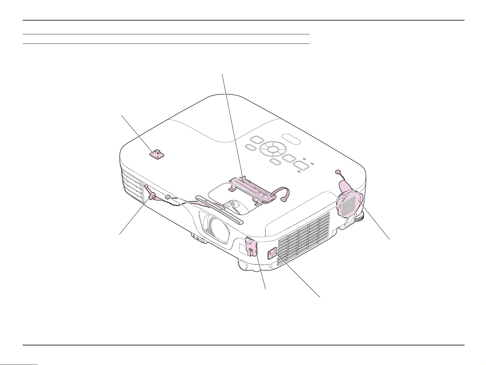
Speaker (p81)
TH Board (2) (p.88)
Shutter Switch (p70)
HK Assy (EB-X11/S12/S12H/X12/
W12/X14 EH-TW480 only) (p69)
IR Board (p.97)
TH Board (1) (p.97)
SENSORS/SPEAKER
Troubleshooting CONFIDENTIAL
Figure 2-5.
SEIKO EPSON 27 Revision C
Page 28
EB-S01/W01/X14G/S11/X11/S0 2/S02H/X02/W02/S12/S12H /X 1 2/ W 12 /X1 4 EH- TW 4 8 0
SW Board (p67)
RS Board
(EB-S11/X11 only) (p.79)
MA Board / RS Board
(EB-S11/X11 only) (p79)
CIRCUIT BOARDS
Troubleshooting CONFIDENTIAL
Figure 2-6.
SEIKO EPSON 28 Revision C
Page 29
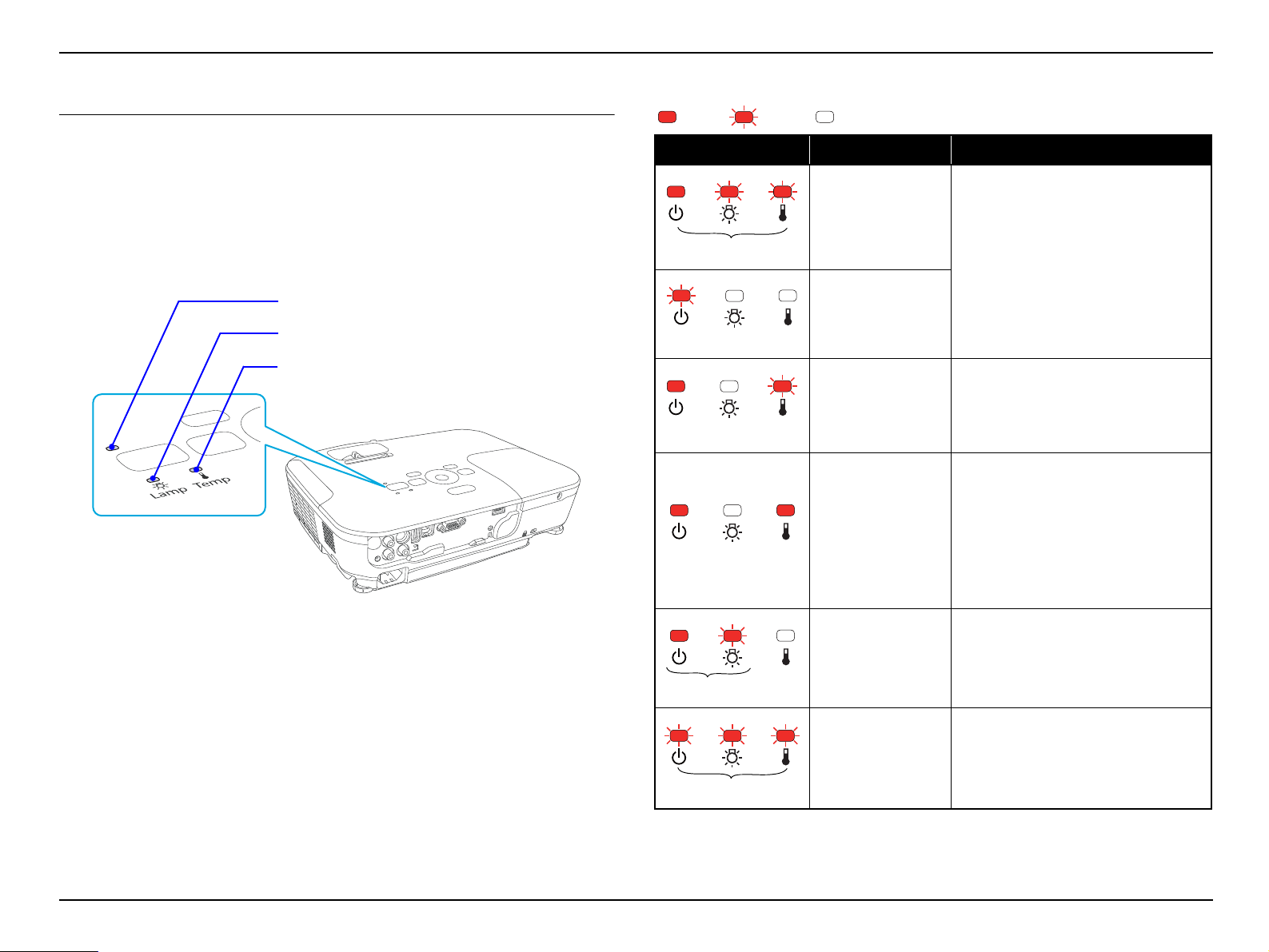
EB-S01/W01/X14G/S11/X11/S0 2/S02H/X02/W02/S12/S12H /X 1 2/ W 12 /X1 4 EH- TW 4 8 0
Temperature LED
Power LED
Lamp LED
Red
Red
* Fast Blink
Red
Red
Red Red
Red
Red
Troubleshooting CONFIDENTIAL
2.4 Error Indication and Problem diagnosis
2.4.1 LED Indication
The control panel on the projector has three LEDs to indicate the projector’s operation
status. When errors occur, you can identify error status with those LED indications.
Figure 2-7. LED Indicators
Abnormal Status
ON Blink OFF
LED Status Error Problem/Error Status
Internal error
Video sub-processor
error
Abnormality is detected from the elements
on MA Board.
Internal error (RAM)
Fan error
Sensor error
High Temp error
(overheating)
Lamp problem
Lamp failure
Abnormality is detected from a fan.
Abnormality is detected from a sensor.
[Phenomenon]
The lamp turns off automatically, and the
projection stops. If the projector has been
left untouched for 5 minutes, it enters the
standby mode.
[Status]
The internal temperature rises over the
specified level.
Abnormality has occurred to the lamp
and the ignition/illumination processes
failed.
Lamp Cover is not securely closed.
SEIKO EPSON 29 Revision C
Power Supply
(Ballast) error
Auto Iris error
Abnormality is detected from Ballast.
Abnormality is detected from Auto
Iris.
Page 30
EB-S01/W01/X14G/S11/X11/S0 2/S02H/X02/W02/S12/S12H /X 1 2/ W 12 /X1 4 EH- TW 4 8 0
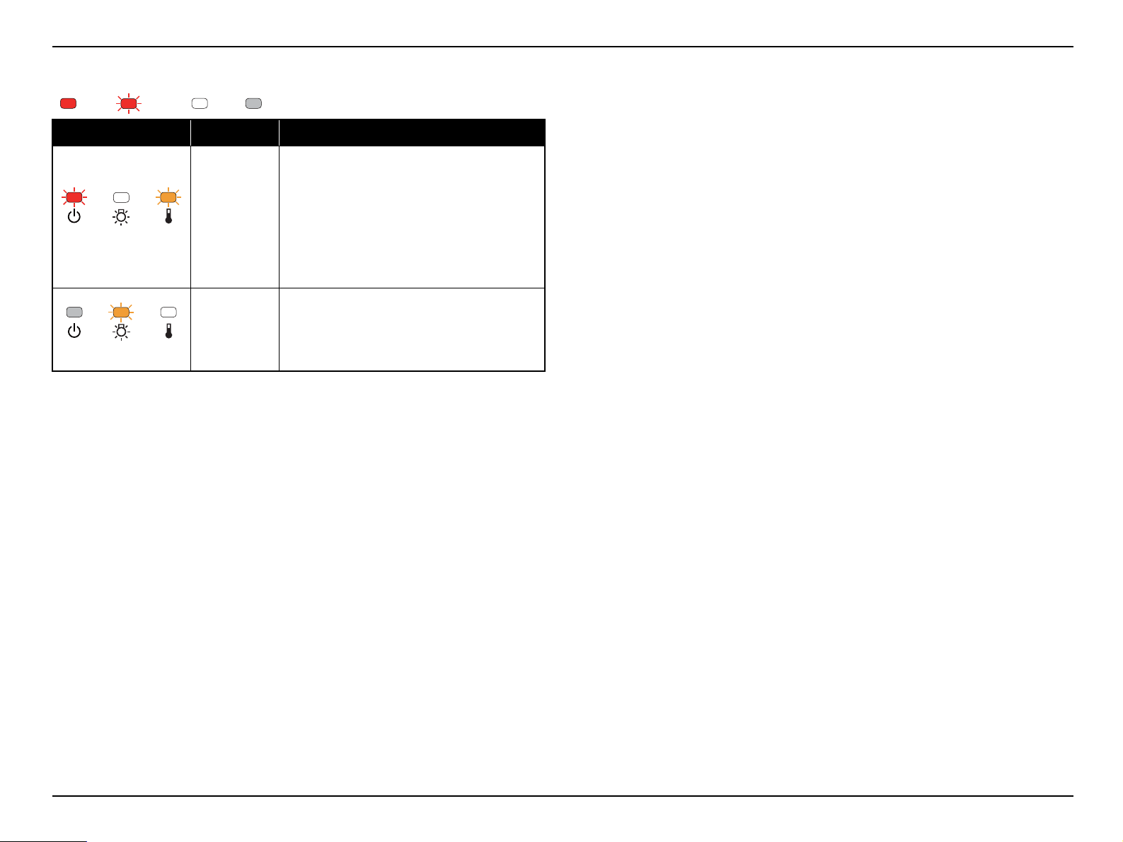
Red
Orange
Orange
Warning Status
ON Blink OFF Varies according to the projector status
LED Status Cause Status/Check point
This is not an abnormality. However, if the
temperature continues to rise higher afterwards,
projection stops automatically.
High Temp
Warning
[Remedy]
Check that the air filter and the exhaust vent
are clear, and that the projector is not placed
against a wall.
If the air filter is clogged, clean or replace it.
Troubleshooting CONFIDENTIAL
Warning to
replace Lamp
Replace the lamp with a new one.
SEIKO EPSON 30 Revision C
Page 31

EB-S01/W01/X14G/S11/X11/S0 2/S02H/X02/W02/S12/S12H /X 1 2/ W 12 /X1 4 EH- TW 4 8 0
Red
Red * Fast Blink
Red
Red
Red
Red
Troubleshooting CONFIDENTIAL
2.4.2 Troubleshooting based on LED Indications
This section describes the LED error indications and corresponding error codes and their remedies.
ON Blink OFF
LED Status
Internal error (1)
Internal error (2)
Fan error
Sensor error
Corresponding error code
and error name
RO ROM error
II I2C error
ID DR error
IV Video sub-processor error
RA RAM error
FN Fan error
SE Sensor error
Remedy Reference
1. Disconnect the AC cable once, and reconnect it, then turn the
power back on.
2. If the same error occurs, connect the PC to the projector and check
the error code on the AS Menu, then carry out the remedy referring
to the reference on the right column.
1. Check the connection between each fan/sensor and MA Board. If
there is a connection failure, connect it correctly.
2. If the same error occurs after turning the power on, connect the PC
to the projector and check the error code on the AS Menu, then
carry out the remedy referring to the reference on the right column.
" Troubleshooting from the
Error Code on Electric Circuit
Errors (p37)"
1. "3.3.6 MA Board (assembly)
(p74)"
2. " Troubleshooting from the
Error Code on Cooling
System Errors (p35)"
High Temp error
(overheating)
TH High Temp error
SEIKO EPSON 31 Revision C
1. Check the Air Filter's condition (dirt accumulation, clogging etc.).
When clogging or similar is found, clean/replace the filter.
2. If the same error occurs after turning the power on, connect the PC
to the projector and check the error code on the AS Menu, then
carry out the remedy referring to the reference on the right column.
1. "3.3.1 Air Filter (p59)"
2. " Troubleshooting from the
Error Code on Cooling
System Errors (p35)"
Page 32

EB-S01/W01/X14G/S11/X11/S0 2/S02H/X02/W02/S12/S12H /X 1 2/ W 12 /X1 4 EH- TW 4 8 0
Red
Red
Troubleshooting CONFIDENTIAL
LED Status
Power Supply error
Lamp error
Corresponding error code
and error name
AI Auto Iris error
PB Power Supply (Ballast) error
LE Lamp burnt out
LF Lamp failure
Remedy Reference
Check the connection of the cables. If there is a connection failure,
connect it correctly.
1. Check the following one by one. After checking and improving, turn
on the power again and check if the same error occurs again.
Lamp Cover status
Secure it if it is loose/open.
Lamp attachment
Check the lamp and secure it if it is loose.
Lamp status (whether the lamp is broken/damaged.)
Take out and check the lamp for damage.
• If the lamp is not cracked: Re-fit the lamp and turn on the power.
If the error continues, replace the lamp with a new one.
• If the lamp is broken/damaged, replace it with a new one.
Air Filter's condition (dirt accumulation, clogging, etc.)
When clogging or similar is found, clean or replace the filter.
When using the projector at an altitude of 1500 m or more, set “High
Altitude Mode” to “On”.
2. If the same error occurs after turning the power on, connect the PC
to the projector and check the error code on the AS Menu, then carry
out the remedy referring to the reference on the right column.
1. "3.3.6 MA Board (assembly)
(p74)"
2. " Troubleshooting from the
Error Code on Electric
Circuit Errors (p37)"
1. "3.3.2 Lamp (p60)"
"3.3.1 Air Filter (p59)"
2. " Troubleshooting from the
Error Code on Lamp Errors
(p34)"
SEIKO EPSON 32 Revision C
Page 33

EB-S01/W01/X14G/S11/X11/S0 2/S02H/X02/W02/S12/S12H /X 1 2/ W 12 /X1 4 EH- TW 4 8 0
Check the Error Code in the error log
from AS menu.
Locate the defective parts referring to the
table below with the Error Code.
Repair/replace the defective parts.
Start
Troubleshooting CONFIDENTIAL
2.4.3 Troubleshooting from the Error Codes
If the projection does not start for some reasons, connect your PC
to the service terminal so as to display the AS menu and check the
error code. To display the AS Menu, see the following: "5.1 AS
(After Service) Menu (p139)"
This section explains the troubleshooting from the error codes displayed on the AS
(after service) Menu to carry out their necessary repair.
Display the AS Menu and switch it to the Error Log window to check the error code,
and locate its remedy from the table below and carry it out.
Figure 2-8. Flowchart of Troubleshooting
SEIKO EPSON 33 Revision C
Page 34

EB-S01/W01/X14G/S11/X11/S0 2/S02H/X02/W02/S12/S12H /X 1 2/ W 12 /X1 4 EH- TW 4 8 0
Troubleshooting CONFIDENTIAL
TROUBLESHOOTING FROM THE ERROR CODE ON LAMP ERRORS
Error code/error name Faulty part/part name Cause Remedy Reference
Lamp Lamp is broken. Replace Lamp. "3.3.2 Lamp (p60)"
LE Lamp Burnt Out error
LF Lamp Failure
BA Unit BA Unit is broken. Replace BA Unit.
Air Filter Air Filter is clogging. Clean Air Filter. Replace it if not improved. "3.3.1 Air Filter (p59)"
PS Filter PS Filter is broken.
Replace PS Filter. "3.3.11.2 PS Filter (p94)"
Safety Switch (AC Cable) Safety Switch (AC Cable) is broken.
Abnormality of the bulb (arc tube) has
Lamp
BA Unit
PS Filter PS Filter is broken. Replace PS Filter. "3.3.11.2 PS Filter (p94)"
occurred.
Lamp is broken.
BA Unit is broken.
Instability of the BA Unit’s drive
waveform has occurred.
Replace Lamp. "3.3.2 Lamp (p60)"
Replace BA Unit.
"3.3.11.1 BA Unit / SCI
Cable (p93)"
"3.3.11.1 BA Unit / SCI
Cable (p93)"
SEIKO EPSON 34 Revision C
Page 35

EB-S01/W01/X14G/S11/X11/S0 2/S02H/X02/W02/S12/S12H /X 1 2/ W 12 /X1 4 EH- TW 4 8 0
Troubleshooting CONFIDENTIAL
TROUBLESHOOTING FROM THE ERROR CODE ON COOLING SYSTEM ERRORS
Error code/error name Faulty part/part name Cause Remedy Reference
Air Filter Air Filter is clogging. Clean Air Filter. Replace it if not improved. "3.3.1 Air Filter (p59)"
TH Overheat error
FN Fan error
TH Board (1)/(2)
TH Cable
Exterior Parts
MA Board
EX Fan
Lamp Fan
INT Fan
MA Board
TH Board is broken. Replace the broken TH Board.
TH Cable is not connected properly. Connect the cable to MA Board correctly.
TH Cable is broken. Replace the broken cable.
Vent's status became worse. (dirt
accumulation/clogging/deformation)
Elements for temperature control on
MA Board are broken.
The fan cable is not connected
properly.
The fan cable is broken. Replace the Fan with the broken cable with a new one.
Blades are broken. Replace the fan with the broken blades with a new one.
Revolutions of the fan has become
abnormal.
Accumulation of dust has occurred on
the fan.
Elements for temperature control on
MA Board are broken.
Clean the vent to remove the foreign material.
Replace the parts with deformed vent.
If the error continues after carrying out the remedies
above, the related circuit on MA Board is broken, so
replace MA Board.
Connect the fan cable correctly.
Replace the abnormal fan.
Clean the fan with foreign material to remove it.
If the error continues after carrying out the remedies
above, the related circuit on MA Board is broken, so
replace MA Board.
• "2.4.6 Cable Connection
and Projector’s Status
(p46)"
• "3.3.6 MA Board
(assembly) (p74)"
• "3.3.10.1 TH Board (2) /
EX Fan (p88)"
• "3.3.12.1 IR Board
(p97)"
• "3.3.5 Upper Case
(assembly) (p62)"
• "3.3.13 Lower Case
(p101)"
"3.3.6 MA Board (assembly)
(p74)"
• "3.3.10.1 TH Board (2) /
EX Fan (p88)"
• "3.3.9 Lamp Fan (p86)"
• "3.3.12.2 INT Fan / TH
Board (1) (p99)"
"3.3.6 MA Board (assembly)
(p74)"
SEIKO EPSON 35 Revision C
Page 36

EB-S01/W01/X14G/S11/X11/S0 2/S02H/X02/W02/S12/S12H /X 1 2/ W 12 /X1 4 EH- TW 4 8 0
Error code/error name Faulty part/part name Cause Remedy Reference
TH Board is broken. Replace the broken TH Board.
TH Board (1)/(2)
TH Cable
SE Sensor error
MA Board
TH Cable is not connected properly. Connect the cable to MA Board correctly.
TH Cable is broken. Replace the broken cable.
Elements for temperature control on
MA Board are broken.
Troubleshooting CONFIDENTIAL
• "2.4.6 Cable Connection
and Projector’s Status
(p46)"
• "3.3.6 MA Board
(assembly) (p74)"
• "3.3.10.1 TH Board (2) /
EX Fan (p88)"
• "3.3.12.1 IR Board
(p97)"
If the error continues after carrying out the remedies
above, the related circuit on MA Board is broken, so
replace MA Board.
"3.3.6 MA Board (assembly)
(p74)"
SEIKO EPSON 36 Revision C
Page 37

EB-S01/W01/X14G/S11/X11/S0 2/S02H/X02/W02/S12/S12H /X 1 2/ W 12 /X1 4 EH- TW 4 8 0
Troubleshooting CONFIDENTIAL
TROUBLESHOOTING FROM THE ERROR CODE ON ELECTRIC CIRCUIT ERRORS
Error code/error name Faulty part/part name Cause Remedy Reference
RA Internal error RAM
RO Internal error ROM
II Internal error I2C
ID Internal error DR
IV Video sub-processor error
AI Auto Iris error
PB Power Supply (Ballast) error
RAM has become abnormal.
MA Board
Input AC power supply
Environment (Temperature
of the customer’s operating
environment)
MA Board MA Board is broken. Replace MA Board.
Auto Iris
MA Board MA Board is broken. Replace MA Board.
BA Unit BA Unit is broken. Replace BA Unit.
SCI Cable
MA Board is broken.
Flash ROM has become deteriorated.
Instability of the input AC Power
Supply. (an external factor)
Access timing error (occurs in a low
temperature environment (Y43series))
The cable is not connected properly. Connect the cable correctly to MA Board.
Auto Iris is broken. Replace Auto Iris. "3.3.8.1 Auto Iris (p83)"
The cable is not connected properly.
SCI Cable is broken. Replace the broken cable.
Replace MA Board.
If not appropriate, request the customer to improve such
instability.
If not appropriate, request the customer to improve the
usage environment.
Connect the SCI cable to BA Unit and MA Board
correctly.
"3.3.6 MA Board (assembly)
(p74)"
• "2.4.6 Cable Connection
and Projector’s Status
(p46)"
• "3.3.6 MA Board
(assembly) (p74)"
"3.3.6 MA Board (assembly)
(p74)"
• "2.4.6 Cable Connection
and Projector’s Status
(p46)"
• "3.3.6 MA Board
(assembly) (p74)"
• "3.3.11.1 BA Unit / SCI
Cable (p93)"
SEIKO EPSON 37 Revision C
Page 38

EB-S01/W01/X14G/S11/X11/S0 2/S02H/X02/W02/S12/S12H /X 1 2/ W 12 /X1 4 EH- TW 4 8 0
Troubleshooting CONFIDENTIAL
2.4.4 Troubleshooting without Error Indications
This section provides troubleshooting procedures based on observed faults.
TROUBLESHOOTING AT POWER-ON
Error Status Faulty part/part name Cause Remedy Reference
SW Cable is not connected properly. Connect the cable to MA Board correctly.
SW Board
SW Board is broken. Replace SW Board.
Cable is not connected properly. Connect the cable to MA Board correctly.
The projector does not operate at
all. (Power indicator does not
light up orange.)
PS Filter
PS Filter is broken.
Interlock Switch (AC Cable) The Interlock Switch cable is broken.
MA Board MA Board is broken. Replace MA Board.
TROUBLESHOOTING ON IMAGE DISPLAY & QUALITY
T
Error Status Faulty part/part name Cause Remedy Reference
The selected input video cable is not
connected correctly.
Projection Lens is broken. Replace Optical Engine.
Projection Lens is broken. Replace Optical Engine.
No image is projected.
(Lamp is lighting.)
Focus cannot be adjusted.
Zoom cannot be adjusted.
Input video signal
MA Board Video Input terminal is broken. Replace MA Board.
Focus Ring Focus Ring is broken. Replace Focus Ring.
Projection Lens
(Optical Engine)
Zoom Ring Zoom Ring is broken. Replace Zoom Ring.
Projection Lens
(Optical Engine)
"3.3.5.1 SW Board
(p67)"
• "2.4.6 Cable
Connection and
Projector’s Status
(p46)"
Replace PS Filter.
Connect the selected input video cable correctly. ---
• "3.3.6 MA Board
(assembly) (p74)"
• "3.3.11.2 PS Filter
(p94)"
"3.3.6 MA Board
(assembly) (p74)"
"3.3.6 MA Board
(assembly) (p74)"
"3.3.8.2 Focus Ring /
Zoom Ring (p85)"
"3.3.8 Optical Engine
(p82)"
"3.3.8.2 Focus Ring /
Zoom Ring (p85)"
"3.3.8 Optical Engine
(p82)"
SEIKO EPSON 38 Revision C
Page 39

EB-S01/W01/X14G/S11/X11/S0 2/S02H/X02/W02/S12/S12H /X 1 2/ W 12 /X1 4 EH- TW 4 8 0
Error Status Faulty part/part name Cause Remedy Reference
HK Assy cable is not connected
properly.
HK Assy cable is broken.
HK Assy is broken.
Horizontal Keystone cannot be
adjusted.
HK Assy
(EB-X11/S12/S12H/X12/
W12/X14/ EH-TW480 only)
Troubleshooting CONFIDENTIAL
Connect the cable to MA Board correctly.
Replace HK Assy.
"3.3.5.2 HK Assy (EBX11/S12/S12H/X12/
W12/X14 EH-TW480
only) (p69)"
Black part of image is reddish.
Black part of image is greenish.
Black part of image is blueish.
Abnormality can be seen on the
projected image.
MA Board MA Board is broken. Replace MA Board.
FPC for L/V (R) is not connected
Optical Engine
MA Board MA Board is broken. Replace MA Board.
Optical Engine
MA Board MA Board is broken. Replace MA Board.
Optical Engine
MA Board MA Board is broken. Replace MA Board.
Optical parts
properly.
FPC for L/V (R) is broken. Replace Optical Engine.
FPC for L/V (G) is not connected
properly.
FPC for L/V (G) is broken. Replace Optical Engine.
FPC for L/V (B) is not connected
properly.
FPC for L/V (B) is broken. Replace Optical Engine.
Deterioration, mal-alignment, or
contamination of the optical part(s).
Connect FPC for L/V (R) to MA Board correctly.
Connect FPC for L/V (G) to MA Board correctly.
Connect FPC for L/V (B) to MA Board correctly.
Clean or replace the optical part(s).
Replace Optical Engine.
"3.3.6 MA Board
(assembly) (p74)"
• "2.4.6 Cable
Connection and
Projector’s Status
(p46)"
• "3.3.6 MA Board
(assembly) (p74)"
• "3.3.8 Optical Engine
(p82)"
"2.4.5 Troubleshooting
on image abnormality
(p44)"
"3.3.8 Optical Engine
(p82)"
SEIKO EPSON 39 Revision C
Page 40

EB-S01/W01/X14G/S11/X11/S0 2/S02H/X02/W02/S12/S12H /X 1 2/ W 12 /X1 4 EH- TW 4 8 0
TROUBLESHOOTING ON AUDIO INPUT/OUTPUT
Error Status F aulty par t/part name Cause Remedy Reference
Cable is not connected properly. Connect the input audio cable correctly. ---
Input Audio cables
Cable is broken. Replace the broken input audio cable. ---
Troubleshooting CONFIDENTIAL
Sound does not come out.
Speaker
MA Board
Speaker cable is not connected
properly.
Cable is broken.
Speaker is broken.
Input terminal is broken.
Elements for audio control on MA
Board are broken.
Connect Speaker cable to MA Board correctly.
Replace Speaker.
If the error continues after carrying out the remedies above, the
related circuit on MA Board is broken, so replace MA Board.
• "2.4.6 Cable
Connection and
Projector’s Status
(p46)"
• "3.3.6 MA Board
(assembly) (p74)"
• "3.3.7 Speaker (p81)"
"3.3.6 MA Board
(assembly) (p74)"
SEIKO EPSON 40 Revision C
Page 41

EB-S01/W01/X14G/S11/X11/S0 2/S02H/X02/W02/S12/S12H /X 1 2/ W 12 /X1 4 EH- TW 4 8 0
TROUBLESHOOTING ON OPERATION ABNORMALITY
Error Status F aulty par t/part name Cause Remedy Reference
Batteries have run out. Replace the batteries with new ones. ---
Remote Controller
Remote Controller is broken. Replace Remote Controller. ---
Troubleshooting CONFIDENTIAL
Operation using Remote
Controller cannot be made.
Operation using Control Panel
cannot be made.
LED does not light.
(Power can turn on.)
RC Filter RC Filter is dirty. Clean RC Filter. If not improved, replace RC Filter.
IR Board IR Board is broken. Replace IR Board.
Cable is not connected properly. Connect the cable between IR Board and MA Board correctly.
RC Cable
Cable is broken. Replace the cable.
MA Board
SW Board SW Board is broken. Replace SW Board.
SW Button
SW Selection Button
SW Cable
MA Board
SW Board SW Board is broken. Replace SW Board.
SW Cable
MA Board
Elements for remote control on MA
Board are broken.
SW Button or SW Selection Button is
not fixed properly or broken.
Cable is not connected properly. Connect the cable correctly.
Cable is broken. Replace the cable.
Elements for operation control on MA
Board are broken.
Cable is not connected properly. Connect the cable correctly.
Cable is broken Replace the cable.
Elements for LED display on MA
Board are broken.
If the error continues after carrying out the remedies above, the
related circuit on MA Board is broken, so replace MA Board.
Re-assemble the SW Button or SW Selection Button. Replace it if
it is broken.
If the error continues after carrying out the remedies above, the
related circuit on MA Board is broken, so replace MA Board.
If the error continues after carrying out the remedies above, the
related circuit on MA Board is broken, so replace MA Board.
"3.3.6 MA Board
(assembly) (p74)"
• "2.4.6 Cable
Connection and
Projector’s Status
(p46)"
• "3.3.6 MA Board
(assembly) (p74)"
• "3.3.12.1 IR Board
(p97)"
"3.3.6 MA Board
(assembly) (p74)"
• "2.4.6 Cable
Connection and
Projector’s Status
(p46)"
• "3.3.6 MA Board
(assembly) (p74)"
• "3.3.5.1 SW Board
(p67)"
"3.3.6 MA Board
(assembly) (p74)"
• "2.4.6 Cable
Connection and
Projector’s Status
(p46)"
• "3.3.6 MA Board
(assembly) (p74)"
• "3.3.5.1 SW Board
(p67)"
"3.3.6 MA Board
(assembly) (p74)"
SEIKO EPSON 41 Revision C
Page 42

EB-S01/W01/X14G/S11/X11/S0 2/S02H/X02/W02/S12/S12H /X 1 2/ W 12 /X1 4 EH- TW 4 8 0
Error Status F aulty par t/part name Cause Remedy Reference
RS Board RS Board is broken. Replace RS Board.
RS-232 cannot be used.
(EB-S11/X11 only)
RC Cable (for RS Board)
Cable is not connected properly. Connect the cable between RS Board and MA Board correctly.
Cable is broken. Replace the cable.
Troubleshooting CONFIDENTIAL
"3.3.6.2 MA Board / RS
Board (EB-S11/X11
only) (p79)"
SEIKO EPSON 42 Revision C
Page 43

EB-S01/W01/X14G/S11/X11/S0 2/S02H/X02/W02/S12/S12H /X 1 2/ W 12 /X1 4 EH- TW 4 8 0
TROUBLESHOOTING ON OTHER ABNORMALITY
Error Status F aulty par t/part name Cause Remedy Reference
Lamp Burn on dust from heat. Clean the area around Lamp to remove dust or the like.
Cable Burn on cables from heat. If burn on cables has occurred, replace them with new ones.
Smoke/Abnormal odor
PS Filter
BA Unit
PS Filter
BA Unit BA Unit is vibrating abnormally. Replace BA Unit.
Burn on a circuit board from heat. Replace PS Filter or BA Unit.
Pulse transformer is vibrating
abnormally.
Troubleshooting CONFIDENTIAL
"3.3.2 Lamp (p60)"
• "3.3.11.2 PS Filter
(p94)"
• "3.3.11.1 BA Unit /
SCI Cable (p93)"
Replace PS Filter.
• "3.3.11.2 PS Filter
(p94)"
• "3.3.11.1 BA Unit /
SCI Cable (p93)"
Abnormal noises
EX Fan
Lamp Fan
INT Fan
Operating parts
Foreign material has stuck on a fan. Clean the fan to remove foreign material.
Fan is touching other parts.
Check if a fan touches other parts. In such a case, correct its
installation.
Fan’s impeller is broken. Replace the broken fan with a new one.
Screws are loose or has been fallen
off.
Tighten the screws or reassemble the parts.
• "3.3.10.1 TH Board
(2) / EX Fan (p88)"
• "3.3.9 Lamp Fan
(p86)"
• "3.3.12.2 INT Fan /
TH Board (1) (p99)"
---
SEIKO EPSON 43 Revision C
Page 44

EB-S01/W01/X14G/S11/X11/S0 2/S02H/X02/W02/S12/S12H /X 1 2/ W 12 /X1 4 EH- TW 4 8 0
Troubleshooting CONFIDENTIAL
2.4.5 Troubleshooting on image abnormality
This section describes this projector’s possible troubles in image quality, and provides identification and troubleshooting pro cedures based on the observed phenomena.
Illumination reduction
Phenomenon Defective part/part name Cause Remedy Reference
The projected image became darker.
COLOR NON-UNIFORMITY
Phenomenon Defective part/part name Cause Remedy Reference
Color non-uniformity can be seen partially
in the projected image.
CONDENSER LENS;
D/FB/FG2/R
BDM/GDM
Mirror;R
MULTI LENS;A
N POLARIZER UNIT;B/R
PBS MASK ASSY.2
Some optical parts might mist for some
reasons.
Some optical parts may become
deteriorated due to the prolonged usage.
Some optical parts may be broken.
Clean the lenses, mirrors with a
nonwoven fabric wiper or
cotton bud moistened with
ethanol.
Replace the defective parts with
new ones.
• "4.2.2 CONDENSER LENS;D/
FB/FG2/R (p125)"
• "4.2.3 BDM/GDM (p129)"
• "4.2.4 MIRROR;R (p131)"
• "4.2.6 MULTI LENS;A (p135)"
• "4.2.1 N POLARIZER UNIT;B/R
(p122)"
• "4.2.5 PBS MASK ASSY.2
(p133)"
SEIKO EPSON 44 Revision C
Page 45

EB-S01/W01/X14G/S11/X11/S0 2/S02H/X02/W02/S12/S12H /X 1 2/ W 12 /X1 4 EH- TW 4 8 0
COLOR BANDING (SHADOW)
Phenomenon Defective part/part name Cause Remedy Reference
There occur “shadows”* on the right and left
side.
MULTI LENS;A
* “Shadow” is a vertical color banding
appearing on the left or right side.
ABNORMAL IMAGE
Troubleshooting CONFIDENTIAL
Some optical parts may be displaced due to
some shock or the like.
Re-assemble the defective parts.
If the phenomenon not
improved, replace the part with a
new one.
If the phenomenon not
improved, replace the Optical
Engine.
• "4.2.6 MULTI LENS;A (p135)"
• "3.3.8 Optical Engine (p82)"
Phenomenon Defective part/part name Cause Remedy Reference
Some abnormality can be seen in the projected
image.
MULTI LENS;A
PBS MASK ASSY.2
Some optical parts may be detached.
Re-assemble the defective parts.
If the phenomenon not
improved, replace the part with a
new one.
• "4.2.6 MULTI LENS;A (p135)"
• "4.2.5 PBS MASK ASSY.2
(p133)"
SEIKO EPSON 45 Revision C
Page 46

EB-S01/W01/X14G/S11/X11/S0 2/S02H/X02/W02/S12/S12H /X 1 2/ W 12 /X1 4 EH- TW 4 8 0
CN1203
C
N
2
0
0
0
CN1102
CN1200
CN1100
CN3301
CN1500 CN1700
CN1600
CN1202
CN1101 CN1205
CN1201
CN1206
CN1900
CN1105
Troubleshooting CONFIDENTIAL
2.4.6 Cable Connection and Projector’s Status
This section describes the projector’s status when a disconnection has occurred somewhere between the parts/units and the MA Board. Refer to the following table and check the
doubted connectors are securely connected. If there is a disconnection or a loose connection, connect it correctly.
Figure 2-9. Connector layout of the MA Board
SEIKO EPSON 46 Revision C
Page 47

EB-S01/W01/X14G/S11/X11/S0 2/S02H/X02/W02/S12/S12H /X 1 2/ W 12 /X1 4 EH- TW 4 8 0
MAL-CONNECTION ON EACH CONNECTOR (MA Board)
Troubleshooting CONFIDENTIAL
Connector
No.
CN1500
CN1600
CN1700
CN1900 Auto Iris AI Auto Iris error
CN1101
CN2000 PS Filter --- ---
Destination
Optical Engine
(L/V(R))
Optical Engine
(L/V(G))
Optical Engine
(L/V(B))
BA Unit
(SCI Cable)
Error Information
Code Name
--- ---
PB
Power Supply
(Ballast) error
Status Reference
When pressing the power button, initialization starts normally, then the pro jection starts. But
the black part of the projected image is reddish.
When pressing the power button, initialization starts normally, then the pro jection starts. But
the black part of the projected image is greenish.
When pressing the power button, initialization starts normally, then the pro jection starts. But
the black part of the projected image is bluish.
(This phenomenon cannot be easily recognized on Logo screen or No Signal screen;
therefore try displaying the menu or the like to check for it.)
The power can turn on and Power LED lights orange. When pressing the power button, the
error message about Auto Iris is displayed on the screen, and advises the user to turn off the
power and to contact the Epson Service. When pressing the p ower button, the LEDs indicate
the warning and after a certain period of cooling the power turns off automatically with two
beeps into error stand-by status. The LED Indicator’s warning display continues until
unplugging the AC cable.
The power can turn on and Power LED lights orange. When pressing the power button,
initialization starts but instantly the projector changes int o the Power Supply (Ballast) Error
status. After a certain period of cooling, the power turns off automatically with two beeps
into error standby status. The LED Indicator’s warning display continues until unplugging
the AC cable.
When the AC cable is connected, the power LED does not light orange. The power button
does not work or power cannot turn on.
"Troubleshooting on image
Display & Quality (p.38)"
"Troubleshooting from the Error
Code on Electric Circuit Errors
(p.37)"
"Troubleshooting from the Error
Code on Electric Circuit Errors
(p.37)"
"Troubleshooting at Power-ON
(p.38)"
CN1102 IR Board --- ---
HK Assy
(EB-X11/S12/
CN1202
CN1100 SW Board --- ---
S12H/X12/W12/
X14/EH-TW480
only)
--- ---
When pressing the power button, initialization starts normally, then the pro jection starts. But
the control from the front cannot be made. The control from the rear is still effective.
When pressing the power button, initialization starts normally, then the pro jection starts. But
the horizontal keystone is automatically corrected to a certain point and a distorted image is
projected. Horizontal Keystone adjustment cannot be made.
When the AC cable is connected, the power LED does not light orange. The power button
does not work or power cannot turn on.
"Troubleshooting on Operation
Abnormality (p.41)"
"Troubleshooting on image
Display & Quality (p.38)"
• "Troubleshooting at Power-ON
(p.38)"
• "Troubleshooting on Operation
Abnormality (p.41)"
SEIKO EPSON 47 Revision C
Page 48

EB-S01/W01/X14G/S11/X11/S0 2/S02H/X02/W02/S12/S12H /X 1 2/ W 12 /X1 4 EH- TW 4 8 0
Troubleshooting CONFIDENTIAL
Connector
No.
CN1105
CN1200 TH Board (1)
CN1201 TH Board (2)
CN1203 INT Fan
CN1205 EX Fan
CN1206 Lamp Fan
CN3301 Speaker --- ---
Destination
RS Board
(EB-S11/X11
only)
Error Information
Code Name
--- ---
SE Sensor error
FN Fan error
Status Reference
When pressing the power button, initialization starts normally, then the pro jection starts. But
the RS-232 cannot be used.
Sensor error occurs while initializing, and LEDs indicate the error, then the projec tor turns
into the abnormal stand-by status.
Fan error occurs while initializing and LEDs indicate the error, then the projector turns into
the abnormal stand-by status.
When pressing the power button, initialization starts normally, th en the pro jec tion starts.
Audio controller on screen display appears, but no sound is output from the speaker even if
the audio input is applied.
"Troubleshooting on Operation
Abnormality (p.41)"
"Troubleshooting from the Error
Code on Cooling System Errors
(p.35)"
"TroubleShooting on Audio
Input/Output (p.40)"
SEIKO EPSON 48 Revision C
Page 49

EB-S01/W01/X14G/S11/X11/S0 2/S02H/X02/W02/S12/S12H /X 1 2/ W 12 /X1 4 EH- TW 4 8 0
Troubleshooting CONFIDENTIAL
2.5 Operation and Safety Check after repair
INITIALIZATION CHECK
After repairing this product, carry out the following initialization check. When
repairing a Safety Device, refer to “ 3.4 Safety Check after Servicing (p103)” and carry
out the necessary procedure for safety.
Procedure Check item
1. Connect the power cable. Does the [Power] LED light orange?
Does the [Power] LED flash green, then light green?
2. Press the [Power] button on the
projector.
Does the lamp light?
2.5.1 Each Operation Check
When repairing this product, carry out the check for each operation if necessary.
OPERATION CHECK FOR SW BOARD/HK ASSY
After repairing SW Board/HK Assy, carry out the check below following the
instructions. (See " Troubleshooting on Operation Abnormality (p41)".)
Procedure Check item
Does the [Power] button switch on/off the projector?
Does the [Source Search] button switch the sources?
Does the [Menu] button display/close the menu?
1. Press the [Power] button on the
projector to turn it on.
2. Check all the buttons on SW Board
if they work properly.
3. Check HK assy whether it works
properly.
Does the [Keystone] button correct vertical
keystone?
Does the [Esc] button stop the current function?
Does the [Enter] button determine the setting you
made?
Does the [Help] button display/close the help menu?
Does HK Assy correct horizontal keystone?
SEIKO EPSON 49 Revision C
Page 50

EB-S01/W01/X14G/S11/X11/S0 2/S02H/X02/W02/S12/S12H /X 1 2/ W 12 /X1 4 EH- TW 4 8 0
Troubleshooting CONFIDENTIAL
OPERATION CHECK FOR REMOTE CONTROLLER
After repairing the remote controller, carry out the check below following the
instructions. (See " Troubleshooting on Operation Abnormality (p41)".)
Procedure Check item
1. Press the [Power] button on the
remote controller to turn the projector
on.
2. Check all the buttons on the remote
controller
3. Check if the front and rear receivers
work properly.
if they work properly.
Does the [Power] button on the controller switch on/
off the projector?
Do all the buttons function correctly?
Can the remote controller work from the front/rear of
the projector?
OPERATION CHECK FOR VIDEO INPUT/OUTPUT
After repairing the parts related with video input/output, carry out the check below
following the instructions. (See " Troubleshooting on image Display & Quality
(p38)".)
Procedure Check item
1. Set the projector on an even
workbench.
2. Press the [Power] button to turn the
power ON.
3. Adjust the projection angle with
Foot.
4. Adjust the focus with Focus Ring.
5. Adjust the image size with Zoom
Ring.
6. Adjust keystone with the [Keystone]
buttons and HK Assy.
7. From the menu, select [Position] and
adjust the image position.
8. Connect all the IF cables and display
an image.
9. Press the [Source Search] button,
and select the corresponding source.
Does the lamp light?
Is the image projected after the lamp lit?
Is “No Signal” message displayed on the screen?
Are focusing and zooming available?
Do the rings smoothly work?
Is the image of the selected input source
projected?
Is image vivid enough?
10.Check the [A/V Mute] function by
pressing the [A/V Mute] button on
Remote Controller.
Is the image turned on/off?
SEIKO EPSON 50 Revision C
Page 51

EB-S01/W01/X14G/S11/X11/S0 2/S02H/X02/W02/S12/S12H /X 1 2/ W 12 /X1 4 EH- TW 4 8 0
Troubleshooting CONFIDENTIAL
OPERATION CHECK FOR AUDIO INPUT/OUTPUT
After repairing the parts related with audio input/output, carry out the check below
following the instructions. (See " TroubleShooting on Audio Input/Output (p40)".)
Procedure Check item
1. Connect your PC to Video and
Audio inputs of MA Board.
2. Press the [Source Search] button and
switch to the corresponding source.
3. Input audio signal to the projector
from your PC, and output sound
from the built-in speaker.
4. Check the [A/V Mute] function by
closing/opening Lens Shutter.
5. Check the [A/V Mute] function by
pressing the [A/V Mute] button on
the remote controller.
Does sound come out from Speaker?
Can you control the volume with the volume
buttons on Remote Controller?
Is sound turned on/off?
INTERNAL CABLE CONNECTION CHECK
Be sure to turn off the power switch and pull out the power cable from the
projector before checking.
When replacing/removing MA Board, make sure to check all the cables are connected
correctly referring to “ 2.4.6 Cable Connection and Projector’s Status (p46)”.
SEIKO EPSON 51 Revision C
Page 52

DISASSEMBLY AND ASSEMBLY
CHAPTER
3
CONFIDENTIAL
Page 53

EB-S01/W01/X14G/S11/X11/S0 2/S02H/X02/W02/S12/S12H /X 1 2/ W 12 /X1 4 EH- TW 4 8 0
Disassembly and Assembly CONFIDENTIAL
3.1 Precautions
This section describes cautions before starting disassembling and assembling this
product. Make sure to read the precautions below before starting.
3.1.1 General Cautions in operation
General cautions for disassembling and assembling this product are provided below.
Cautions for each procedure are provided in its corresponding section. Make sure to
refer to them before starting.
Do not touch the lamp or the parts around it. They are extremely hot even
after the cooling down operation completed. If any maintenance work
inside the projector is necessary soon after the projector is in operation,
leave the unit until it becomes cool enough before performing maintenance
work.
Never use the air blowers such as a lens cleaner, etc. that contain
flammable gas in repair/maintenance work.
When carrying out any of the following operations, check that there is no
dust or dirt on any component or on any glass surface before installation. If
any contamination is found, clean it off using isopropyl alcohol.
• Optical Engine removal
• Lamp removal
When the projector is disassembled, the dust in and around parts (such as
those on the fans or air filter) may get transferred to other parts such as the
R, G and B light valves which are the central part of the display
mechanism. This may have an adverse effect on the quality of projected
images. Accordingly, be sure to check whether any of the parts are dusty or
dirty, and use a vacuum cleaner to clean them first before carrying out
disassembly/reassembly work.
After reassembling the product, check the followings before turning the
power on.
• All the parts and screws are installed and secured to the proper
positions.
• No cables are caught in the metal frames.
Do not disass emble any components not as specified in this Service Manual.
The Optical Engine, the circuit boards are very sensitive to static
electricity; therefore, be sure to take appropriate measures to prevent static
destruction such as to place them inside static-proof bags once they have
been removed from the projector.
The Optical Engine is very sensitive to vibration and shocks; therefore,
make sure to handle it with care.
The speaker unit contains a permanent magnet; therefore, make sure to
keep it away from any storage media such as floppy disks or magnetic
cards.
Be careful not to drop a metal part such as a screw, a washer, or a clip into
the inside of the product. If such cases should occur accidentally, never
turn on the power supply until all the dropped parts are found and
removed.
SEIKO EPSON 53 Revision C
Page 54

EB-S01/W01/X14G/S11/X11/S0 2/S02H/X02/W02/S12/S12H /X 1 2/ W 12 /X1 4 EH- TW 4 8 0
Disassembly
Disassemble the product
following the given instructions.
Repair/Maintenance
Perform the repair and cleaning,
etc.
Finish
Safety Check after servicing
Refer to “Safety Check after
servicing (p.103)”, and carry out
the required safety checks.
When carrying out repair or
maintenance of a safety device.
Reassembly
Unless otherwise specified,
reassembly is the reverse of the
disassembly procedure.
Disassembly and Assembly CONFIDENTIAL
3.1.2 Precautions
The precautions given below must be always observed whenever disassembling/
reassembling the projector to ensure the safety of service personnel and maintain the
quality.
Do not wear the metal products such as a wrist watch, cuff buttons, rings,
tie-pin etc. to avoid getting into an unsafe state due to touch in g th e
projector.
When disassembling/assembling the projector, be sure to turn off the
power switch and pull out the power cable from the projector beforehand.
When disassembling/assembling the projector, be sure to wear the gloves
and static discharge equipment such as an anti-static wrist strap and a mat.
When replacing the circuit component such as a board or the optical
engine, be sure to contact the anti-static case containing the new one to the
metal part of this product before taking it out.
Disconnect all the interface cables from the projector.
Before disassembling the projector, make sure to clean dust or dirt on the
air filter, the interface section and outer cases using a vacuum cleaner or
the like.
When treating the non-after-service-parts as an assembly in this section,
they are indicated as “Upper Case (assembly)”.
3.1.3 Workflow
SEIKO EPSON 54 Revision C
Page 55

EB-S01/W01/X14G/S11/X11/S0 2/S02H/X02/W02/S12/S12H /X 1 2/ W 12 /X1 4 EH- TW 4 8 0
Standard Operation Time:
The total time to disassemble/
reassemble the target part
following the shortest
procedure.
Shortest Procedure:
The shortest way to remove the
target part.
Disassembly and Assembly CONFIDENTIAL
3.1.4 Standard Operation Time
The standard operation time for each operation is provided at the beginning of each
part. Use the time as a guideline for actual operation.
Basis for the standard operation time
A service employee would have sufficient knowledge for the target product’s
structure, and be able to disassemble/reassemble the product without any
reference to guide books.
Each operation time is the total time of disassembling/removing the target part
following the given shortest procedure, and reassembling it.
Guide to the standard operation time
3.1.5 Tools
The following table indicates the tools recommended for the use of disassembly,
reassembly and adjustment.
Tool Name Qt. Application
Phillips screwdriver No. 00 (8 cm) 1
Phillips screwdriver No. 0 (8 cm) 1
Phillips screwdriver No. 1 (10 cm) 1
Phillips screwdriver No. 2 (10 cm) 1
Hexagonal box screwdriver (5 mm) 1 Removing the computer interface
Tweezers 1
Heat-resistant tape q.s.*
Brush 1 Cleaning away dust
Vacuum cleaner 1 Cleaning away dust
Lens cleaner q.s.*
Gloves 1 pair
Anti-static wrist band 1
Lubricant *
2
q.s.*
Disassembling the focus ring and the
zoom ring
Disassembling the outer cases and
inner components
Removing the Air Filter Cover Band
and disassembling the Front Foot
Securing cables.
Use commercially available Polyim ide
1
tape generally called “KAPTON®
TAPE”.
1
Cleaning the projection lens
---
---
Lubricating the shutter and its frame.
1
(See Shutter Switch (p.70))
Note : *1 q.s.: Sufficient quantity
2
Specified Lubricant: G-78 (AQUADRY W-0082)
*
SEIKO EPSON 55 Revision C
Page 56

EB-S01/W01/X14G/S11/X11/S0 2/S02H/X02/W02/S12/S12H /X 1 2/ W 12 /X1 4 EH- TW 4 8 0
Start
“ 3.3.2 Lamp (p60)” “ 3.3.1 Air Filter (p59)”
“ 3.3.5 Upper Case
(assembly) (p62)”
“ 3.3.6 MA Board
(assembly) (p74)”
“ 3.3.8 Optical
Engine (p82)”
“ 3.3.8.2 Focus Ring /
Zoom Ring (p85)”
“ 3.3.4 Front Foot
(p62)”
“ 3.3.3 Rear Foot (p61)”
Disassembly and Assembly CONFIDENTIAL
3.2 Flowchart
The general disassembly procedure for the EB-S01/W01/X14G/S11/X11/S02/S02H/
X02/W02/S12/S12H/X12/W12/X14 EH-TW480 projectors is illustrated in flowchart
below. Unless otherwise specified, all reassembly should be carried out by following
the disassembly procedures in reverse, therefore reassembling procedures are omitted.
The part names in this chapter are simplified. See the
“Reference (Part Names given in the SPI) (p.116)” for the
corresponding official names.
The parts in yellow are target parts in their category. They
are explained in details in the corresponding sections so as to
reach the parts in the shortest way.
The parts in white are those which are required to be
removed to reach the parts in yellow.
CONSUMABLES/OPTIONS
SEIKO EPSON 56 Revision C
Page 57

EB-S01/W01/X14G/S11/X11/S0 2/S02H/X02/W02/S12/S12H /X 1 2/ W 12 /X1 4 EH- TW 4 8 0
Start
"3.3.1 Air Filter
(p59)"
"3.3.2 Lamp (p60)"
"3.3.6 MA Board
(assembly) (p74)"
"3.3.3 Rear Foot (p61)"
"3.3.4 Front Foot
(p62)"
"3.3.5 Upper Case
(assembly) (p62)"
"3.3.7 Speaker (p81)"
"3.3.8 Optical Engine
(p82)"
"3.3.9 Lamp Fan (p86)"
"3.3.6.1 IF Case
(p78)"
"3.3.5.1 SW Board
(p67)"
"3.3.5.2 HK Assy (EB-
X11/S12/S12H/X12/W12/
X14 EH-TW480 only)
"3.3.5.3 Shutter Switch
(p70)"
"3.3.5.4 Upper
Case (p72)"
"3.3.10 EX Duct
(assembly) (p87)"
"3.3.11 BA Power
Supply (assembly)
(p89)"
"3.3.12 INT Duct
(assembly) (p96)"
"3.3.13 Lower Case
(p101)"
Start
"3.3.1 Air Filter
(p59)"
"3.3.2 Lamp (p60)"
"3.3.5 Upper Case
(assembly) (p62)"
"3.3.6 MA Board
(assembly) (p74)"
"3.3.5.1 SW Board
(p67)"
"3.3.5.2 HK Assy (EB-
X11/S12/S12H/X12/W12/
X14 EH-TW480 only)
"3.3.6.2 MA Board /
RS Board (EB-S11/
X11 only) (p79)"
"3.3.5.3 Shutter
Switch (p70)"
"3.3.8 Optical
Engine (p82)"
"3.3.6.1 IF Case (p78)"
"3.3.10 EX Duct
(assembly) (p87)"
"3.3.11 BA Power
Supply (assembly)
(p89)"
"3.3.10.1 TH Board (2) /
EX Fan (p88)"
"3.3.12 INT Duct
(assembly) (p96)"
"3.3.12.1 IR Board
(p97)"
"3.3.11.2 PS Filter
(p94)"
"3.3.11.1 BA Unit / SCI
Cable (p93)"
"3.3.9 Lamp Fan
(p86)"
"3.3.8.1 Auto Iris
(p83)"
Disassembly and Assembly CONFIDENTIAL
HOUSINGS ELECTRIC CIRCUIT PARTS/OPTICAL PART
SEIKO EPSON 57 Revision C
Page 58

EB-S01/W01/X14G/S11/X11/S0 2/S02H/X02/W02/S12/S12H /X 1 2/ W 12 /X1 4 EH- TW 4 8 0
Start
"3.3.1 Air Filter
(p59)"
"3.3.2 Lamp (p60)"
"3.3.5 Upper Case
(assembly) (p62)"
"3.3.9 Lamp Fan
(p86)"
"3.3.6 MA Board
(assembly) (p74)"
"3.3.8 Optical Engine
(p82)"
"3.3.10 EX Duct
(assembly) (p87)"
"3.3.11 BA Power
Supply (assembly)
(p89)"
"3.3.12 INT Duct
(assembly) (p96)"
"3.3.12.1 IR Board
(p97)"
"3.3.12.2 INT Fan /
TH Board (1) (p99)"
"3.3.10.1 TH Board (2)
/ EX Fan (p88)"
COOLING MECHANISM DEVICES
Disassembly and Assembly CONFIDENTIAL
SEIKO EPSON 58 Revision C
Page 59

EB-S01/W01/X14G/S11/X11/S0 2/S02H/X02/W02/S12/S12H /X 1 2/ W 12 /X1 4 EH- TW 4 8 0
Air Filter
Air Filter Cover
Hooks
Air Filter Cover Band
Disassembly and Assembly CONFIDENTIAL
3.3 Disassembly
This section explains one of the shortest ways to reach the target part to repair. The
parts to be removed in advance are indicated in italic with their reference pages, so
remove those parts referring to their pages before starting.
3.3.1 Air Filter
Standard Operation Time 1 Min.
1. Open the Air Filter Cover.
2. Remove the Air Filter.
3. Release the hooks of the Air Filter Cover Band using tweezers or a similar tool,
and then remove the Air Filter Cover.
Figure 3-1.
SEIKO EPSON 59 Revision C
Page 60

EB-S01/W01/X14G/S11/X11/S0 2/S02H/X02/W02/S12/S12H /X 1 2/ W 12 /X1 4 EH- TW 4 8 0
Lamp Cover
Lamp
Disassembly and Assembly CONFIDENTIAL
3.3.2 Lamp
Standard Operation Time - Min.
This part is designated as the Safety Device.When removing/
replacing the part for repair, be sure to refer to “3.4 Safety Check
after Servicing (p.103)”. According to the instructions in it,
handle the part and perform the procedure after servicing.
1. Loosen the screw and remove the Lamp Cover.
2. Loosen the two screws and remove the Lamp.
Figure 3-3.
Figure 3-2.
SEIKO EPSON 60 Revision C
Page 61

EB-S01/W01/X14G/S11/X11/S0 2/S02H/X02/W02/S12/S12H /X 1 2/ W 12 /X1 4 EH- TW 4 8 0
E1
IF side
Marking
(Letters such as
E2 are engraved)
Rear Foot
Rear Foot
Foot Rubber
Rear Foot
Disassembly and Assembly CONFIDENTIAL
3.3.3 Rear Foot
Standard Operation Time 1 Min.
When removing the Rear Foot, make sure to align the marking on the bottom to
the IF side first, and then pull the foot out. Since there are two hooks on the
screw part of the foot, aligning them to the grooves on the screw hole of the
Lower Case before removal will prevent damage to the Rear Foot.
1. Turn the Rear Foot counterclockwise and pull the foot out to remove it.
Figure 3-4.
2. Remove the Foot Rubber from the Rear Foot.
Figure 3-5.
SEIKO EPSON 61 Revision C
Page 62

EB-S01/W01/X14G/S11/X11/S0 2/S02H/X02/W02/S12/S12H /X 1 2/ W 12 /X1 4 EH- TW 4 8 0
Hook
Front Foot
Tweezers
C.B.P-TITE SCREW,2.5X10,F/ZN-3C
Lower Case
Upper Case
(assembly)
Disassembly and Assembly CONFIDENTIAL
3.3.4 Front Foot
Standard Operation Time 1 Min.
1. Insert the tips of tweezers or a similar tool into the holes on both sides of the Front
Foot to release the hooks, and remove the Front Foot.
3.3.5 Upper Case (assembly)
Standard Operation Time 4 Min.
1. Remove the Air Filter. (p.59)
2. Remove the Lamp. (p.60)
3. Remove the five screws on the bottom of the projector.
Figure 3-6.
Figure 3-7.
SEIKO EPSON 62 Revision C
Page 63

EB-S01/W01/X14G/S11/X11/S0 2/S02H/X02/W02/S12/S12H /X 1 2/ W 12 /X1 4 EH- TW 4 8 0
Don’t touch here!!
Don’t touch here!!
[Nichicon Board’s Case]
[Panasonic Board’s Case]
After removing the Upper Case, DO NOT TOUCH the red-circled points shown in the figure because a high voltage is applied there.
Disassembly and Assembly CONFIDENTIAL
SEIKO EPSON 63 Revision C
Page 64

EB-S01/W01/X14G/S11/X11/S0 2/S02H/X02/W02/S12/S12H /X 1 2/ W 12 /X1 4 EH- TW 4 8 0
10kΩ
When working, make sure to wear insulated gloves such as rubber gloves and pay attention not to get electric shock.
When connecting the terminals, use crocodile clips and make sure to securely connect them.
Example of removing electricity
1. Unplug the AC cable and remove the Upper Case and PS Duct.
2. Connect the two terminals shown below through a 10 kOhm resistance. (Electric discharging will take about 10 seconds.)
3. After the resistance connected in Step 2 is removed, measure the voltage between the two terminals. Restart the work after making sure the voltage drops below 60V.
Disassembly and Assembly CONFIDENTIAL
SEIKO EPSON 64 Revision C
Page 65

EB-S01/W01/X14G/S11/X11/S0 2/S02H/X02/W02/S12/S12H /X 1 2/ W 12 /X1 4 EH- TW 4 8 0
C.B.P-TITE SCREW,2.5X10,F/ZN-3C
Upper Case (assembly)
MA Board
SW Cable
Cable (HK Assy)
Model Plate
In the next step, make sure not to pull away the Upper Case (assembly) too far
because the cables are connected to the case.
4. Remove the five screws on top (Upper Case side).
5. Disconnect the SW Cable and the cable of HK Assy from the MA Board, and
remove the Upper Case (assembly).
6. Remove the Model Plate from the Upper Case (assembly).
Disassembly and Assembly CONFIDENTIAL
Figure 3-8.
SEIKO EPSON 65 Revision C
Page 66

EB-S01/W01/X14G/S11/X11/S0 2/S02H/X02/W02/S12/S12H /X 1 2/ W 12 /X1 4 EH- TW 4 8 0
WARNING LABEL,Sheet
(Part D)
WARNING LABEL,Sheet
(Part A)
WARNING LABEL,Sheet
(Part B)
WARNING LABEL,Sheet
(Part C)
WARNING LABEL,Sheet
(Part E)
Checking Caution Labels
These parts (Caution Labels) are designated as Safety Devices.
When removing/replacing the part for repair, be sure to refer to
“3.4 Safety Check after Servicing (p.103)”. According to the
instructions in it, handle the part and perform the procedure after
servicing.
Disassembly and Assembly CONFIDENTIAL
When replacing the Upper Case (with caution labels attached), make sure to
transfer the labels to the new one.
Check if all the caution label is attached on the location shown below.
SEIKO EPSON 66 Revision C
Page 67

EB-S01/W01/X14G/S11/X11/S0 2/S02H/X02/W02/S12/S12H /X 1 2/ W 12 /X1 4 EH- TW 4 8 0
C.B.P-TITE SCREW,2.5X6,F/ZN-3C
LED Lens
SW Cable
SW Board
Shutter Switch
Upper Case (assembly)
SW Selection Button
SW Button
3.3.5.1 SW Board
Standard Operation Time 5 Min.
1. Remove the Air Filter. (p.59)
Disassembly and Assembly CONFIDENTIAL
2. Remove the Lamp. (p.60)
3. Remove the Upper Case (assembly). (p.62)
4. Remove the three screws and remove the SW Board.
5. Disconnect the Shutter Switch cable from the SW Board.
6. Remove the SW Cable.
7. Remove the two screws and remove the SW Button.
8. Remove the following parts from the Upper Case (assembly).
•LED Lens
• SW Selection Button
Figure 3-9.
SEIKO EPSON 67 Revision C
Page 68

EB-S01/W01/X14G/S11/X11/S0 2/S02H/X02/W02/S12/S12H /X 1 2/ W 12 /X1 4 EH- TW 4 8 0
40 mm
28 mm
60 mm 50 mm
30 mm
16 mm 20 mm
Mountain fold
Valley fold
SW Cable
SW Board
Fold the SW Cable at the points shown below.
Disassembly and Assembly CONFIDENTIAL
SEIKO EPSON 68 Revision C
Page 69

EB-S01/W01/X14G/S11/X11/S0 2/S02H/X02/W02/S12/S12H /X 1 2/ W 12 /X1 4 EH- TW 4 8 0
C.B.P-TITE SCREW,2.5X6,F/ZN-3C
HK Assy
Upper Case (assembly)
HK Insulation Plate
Disassembly and Assembly CONFIDENTIAL
3.3.5.2 HK Assy (EB-X11/S12/S12H/X12/W12/X14 EH-TW480
only)
Standard Operation Time 5 Min.
1. Remove the Air Filter. (p.59)
2. Remove the Lamp. (p.60)
3. Remove the Upper Case (assembly). (p.62)
4. Remove the four screws and remove the HK Insulation Plate and HK Assy.
SEIKO EPSON 69 Revision C
Figure 3-10.
Page 70

EB-S01/W01/X14G/S11/X11/S0 2/S02H/X02/W02/S12/S12H /X 1 2/ W 12 /X1 4 EH- TW 4 8 0
Shutter Frame
Lubrication point
C.B.P-TITE SCREW,2.5X6,F/ZN-3C
C.P.P-TITE SCREW,2X6,F/ZN-3C
Shutter Frame
Shutter Switch
Shutter Spring
Shutter Ball
Shutter Sheet
Lens Shutter
Hooks
3.3.5.3 Shutter Switch
Standard Operation Time 10 Min.
1. Remove the Air Filter. (p.59)
Disassembly and Assembly CONFIDENTIAL
2. Remove the Lamp. (p.60)
3. Remove the Upper Case (assembly). (p.62)
4. Remove the SW Board. (p.67)
5. Remove the HK Assy. (p.69)
6. Remove the two screws ( ).
7. Release the two hooks of the Shutter Frame and remove the Shutter Frame.
8. Remove the screw ( ) and remove the Shutter Switch from the Shutter Frame.
9. Remove the following parts from the Shutter Frame.
• Shutter Ball
• Shutter Spring
• Lens Shutter
10. Remove the Shutter Sheet from the Lens Shutter.
When the sliding action of the shutter becomes awkward, apply grease in the size
of a grain of rice to the points indicated in the figure below.
Figure 3-11.
SEIKO EPSON 70 Revision C
Page 71

EB-S01/W01/X14G/S11/X11/S0 2/S02H/X02/W02/S12/S12H /X 1 2/ W 12 /X1 4 EH- TW 4 8 0
EB-S11/X11/S12/S12H/X12/W12/X14
(1) Route the Shutter Switch through the five ribs of Shutter Frame as
shown below.
Rib
(2) Then route the Shutter Switch between the boss and the rib of Upper
Case (assembly) as shown below.
Upper Case (assembly)
(photo:EB-S11/X11/S12/S12H/
X12/W12/X14)
EB-S01/W01/X14G/S02/S02H/X02/W02
(1) Route the Shutter Switch through three rib As of Upper Case (assembly).
(2) Then route the Shutter Switch between the boss and rib B of Upper Case
(assembly).
Boss
Rib
Boss(2)
Rib A
Shutter Switch
Rib B
Boss
Shutter Switch
Shutter Frame
Disassembly and Assembly CONFIDENTIAL
Route the Shutter Switch cable according to the instructions by model below.
SEIKO EPSON 71 Revision C
Page 72

EB-S01/W01/X14G/S11/X11/S0 2/S02H/X02/W02/S12/S12H /X 1 2/ W 12 /X1 4 EH- TW 4 8 0
C.B.P-TITE SCREW,2.5X6,F/ZN-3C
Upper Case
PLATE,NUT;M3
Upper Case Cover
EX Louver
Front Slit
Air Filter Cover Band
Hooks
3.3.5.4 Upper Case
Standard Operation Time 13 Min.
1. Remove the Air Filter. (p.59)
2. Remove the Lamp. (p.60)
3. Remove the Upper Case (assembly). (p.62)
4. Remove the SW Board. (p.67)
5. Remove the HK Assy. (p.69)
6. Remove the Shutter Switch. (p.70)
Disassembly and Assembly CONFIDENTIAL
7. Remove the two screws ( ) and remove the EX Louver.
8. Remove the six screws ( ) and release the two hooks on the Upper Case to
remove the Front Slit.
9. Remove the two screws ( ) and remove the Upper Case Cover.
10. Remove the following parts from the Upper Case.
• PLATE NUT M3
• Air Filter Cover Band
Figure 3-12.
SEIKO EPSON 72 Revision C
Page 73

EB-S01/W01/X14G/S11/X11/S0 2/S02H/X02/W02/S12/S12H /X 1 2/ W 12 /X1 4 EH- TW 4 8 0
Upper Case
Upper Cushion C
Upper Cushion B
Shutter Cushion B
Upper Cushion A
Shutter Cushion A
11. Remove the following parts from the Upper Case.
• Upper Cushion A x 2
• Upper Cushion B
• Upper Cushion C
• Shutter Cushion A x 2
• Shutter Cushion B x 2
Disassembly and Assembly CONFIDENTIAL
SEIKO EPSON 73 Revision C
Figure 3-13.
Page 74

EB-S01/W01/X14G/S11/X11/S0 2/S02H/X02/W02/S12/S12H /X 1 2/ W 12 /X1 4 EH- TW 4 8 0
MA Board
CN1203
CN1102
CN1200
CN1100
CN3301
CN1202
CN1500 CN1700
CN1600
C
N
2
0
0
0
CN1101 CN1205
CN1201
CN1206
CN1900
CN1105
Table 3-1. Connector Numbers and Destinations
CN No. Destination CN No. Destination
CN1100 SW Board CN1205 EX Fan
CN1101 BA Unit (SCI) CN1206 Lamp Fan
CN1102 IR Board CN1500 Optical Engine (L/V (R))
CN1105 RS Board *
1
CN1600 Optical Engine (L/V (G))
CN1200 TH Board (1) CN1700 Optical Engine (L/V (B))
CN1201 TH Board (2) CN1900 Auto Iris
CN1202 HK Assy *
2
CN2000 PS Filter
CN1203 INT Fan CN3301 Speaker
3.3.6 MA Board (assembly)
Standard Operation Time 6 Min.
1. Remove the Air Filter. (p.59)
2. Remove the Lamp. (p.60)
3. Remove the Upper Case (assembly). (p.62)
4. Disconnect all the cables from the connectors on the MA Board.
Disassembly and Assembly CONFIDENTIAL
Reference
Note *1: EB-S11/X11 only
*2: EB-X11/S12/S12H/X12/W12/X14 EH-TW480 only
Figure 3-14.
SEIKO EPSON 74 Revision C
Page 75

EB-S01/W01/X14G/S11/X11/S0 2/S02H/X02/W02/S12/S12H /X 1 2/ W 12 /X1 4 EH- TW 4 8 0
C.C.SCREW,2.5X6,F/ZN-3C
C.B.P-TITE SCREW,2.5X10,F/ZN-3C
MA Board (assembly)
1
2
3
4
* Make sure to perform #4 routing before
installing the MA Board (assembly).
5. Remove the two screws and remove the MA Board (assembly).
Disassembly and Assembly CONFIDENTIAL
Routing around the MA Board (assembly) (Routing 1 to 4)
According to the cautions below, route the following cables around the
Board
(assembly).
1. Routing of INT Fan cable, RC cable, TH cable
2. Routing of PS Filter cable, SCI Cable
3. Routing of Auto Iris cable, Lamp Fan cable
4. Routing of Auto Iris cable (* Before installing the MA Board
(assembly)
MA
)
Figure 3-16.
Figure 3-15.
SEIKO EPSON 75 Revision C
Page 76

EB-S01/W01/X14G/S11/X11/S0 2/S02H/X02/W02/S12/S12H /X 1 2/ W 12 /X1 4 EH- TW 4 8 0
1
Route the above three cables on the INT
Duct (assembly) and secure them with
Polyimide tape as shown on the left.
Do not route the cables
over the area enclosed
in .
MA Board
(assembly)
2
MA Board
(assembly)
Power cable
When connecting the
Power cable, hold either of
the areas enclosed in .
SCI Cable
Twist the excess wires of the SCI
Cable and put them in the hole here.
Disassembly and Assembly CONFIDENTIAL
1. Routing the INT Fan cable, RC cable, and TH cable
2. Routing the PS Filter cable and SCI Cable
Figure 3-17.
Figure 3-18.
SEIKO EPSON 76 Revision C
Page 77

EB-S01/W01/X14G/S11/X11/S0 2/S02H/X02/W02/S12/S12H /X 1 2/ W 12 /X1 4 EH- TW 4 8 0
3
MA Board
(assembly)
4
Pull out the Auto Iris
cable and the Lamp Fan
cable from the hole
enclosed in .
Wrap the Lamp Fan
cable around the Auto
Iris cable, and connect
the cable to the MA
Board (assembly).
Before installing the MA Board
(assembly), twist the wires of the Auto
Iris cable to prevent falling the wires
apart.
3. Routing the Auto Iris cable and Lamp Fan cable
4. Routing the Auto Iris cable
Disassembly and Assembly CONFIDENTIAL
Figure 3-19.
SEIKO EPSON 77 Revision C
Page 78

EB-S01/W01/X14G/S11/X11/S0 2/S02H/X02/W02/S12/S12H /X 1 2/ W 12 /X1 4 EH- TW 4 8 0
C.BSCREW,2X6,F/NI
C.P.SCREW,2X4,F/ZN-3C
C.C.SCREW,2.5X6,F/ZN-3C
IF Case
MA Shield Plate
MA Insulation Sheet
MA Board (assembly)
RC Filter
3.3.6.1 IF Case
Standard Operation Time 8 Min.
1. Remove the Air Filter. (p.59)
2. Remove the Lamp. (p.60)
3. Remove the Upper Case (assembly). (p.62)
4. Remove the MA Board (assembly). (p.74)
5. Remove the two screws and remove the IF Case.
6. Remove the RC Filter from the IF Case.
7. Remove the two screws and remove the MA Shield Plate.
8. Remove the MA Insulation Sheet from the MA Board (assembly).
Disassembly and Assembly CONFIDENTIAL
Figure 3-20.
SEIKO EPSON 78 Revision C
Page 79

EB-S01/W01/X14G/S11/X11/S0 2/S02H/X02/W02/S12/S12H /X 1 2/ W 12 /X1 4 EH- TW 4 8 0
C.C.SCREW,2.5X6,F/ZN-3C
C.B.P-TITE SCREW,3X8,F/ZN-3C
C.B.SCREW,3X6,F/NI
1/4-40X1/4,H.H.,F/NI,O SCREW
MA Board
MA Plate
IF Shade Case
INT Fan Cushion
Hooks
RS Board
RC Cable
3.3.6.2 MA Board / RS Board (EB-S11/X11 only)
Standard Operation Time 12 Min.
MA Board is designated as the Safety Device.When removing/
replacing the MA Board for repair, be sure to refer to “3.4 Safety
Check after Servicing (p.103)”. According to the instructions in
it, handle the part and perform the procedure after servicing.
Disassembly and Assembly CONFIDENTIAL
1. Remove the Air Filter. (p.59)
2. Remove the Lamp. (p.60)
3. Remove the Upper Case (assembly). (p.62)
4. Remove the MA Board (assembly). (p.74)
5. Remove the IF Case. (p.78)
6. Remove the seven screws.
7. Release the hook of the IF Shade Case from MA Plate and remove the IF Shade
Case and the MA Plate.
8. Remove the INT Fan Cushion from the MA Board.
9. Remove the RS Board from the IF Shade Case.
(EB-S11/X11 only)
Figure 3-21.
SEIKO EPSON 79 Revision C
Page 80

EB-S01/W01/X14G/S11/X11/S0 2/S02H/X02/W02/S12/S12H /X 1 2/ W 12 /X1 4 EH- TW 4 8 0
MA Plate
Polyimide tape
Polyimide tape=20x10mm (2 sheet putting)
Encompass the edge (Blue line part) and put tape.
Disassembly and Assembly CONFIDENTIAL
Figure 3-22.
SEIKO EPSON 80 Revision C
Page 81

EB-S01/W01/X14G/S11/X11/S0 2/S02H/X02/W02/S12/S12H /X 1 2/ W 12 /X1 4 EH- TW 4 8 0
Speaker
INT Fan Cushion
INT Fan Cushions
3.3.7 Speaker
Standard Operation Time 6 Min.
1. Remove the Air Filter. (p.59)
2. Remove the Lamp. (p.60)
3. Remove the Upper Case (assembly). (p.62)
4. Remove the MA Board (assembly). (p.74)
5. Remove the Speaker from the Lower Case.
6. Remove the INT Fan Cushion (x 2) from the Speaker.
Disassembly and Assembly CONFIDENTIAL
SEIKO EPSON 81 Revision C
Figure 3-23.
Page 82

EB-S01/W01/X14G/S11/X11/S0 2/S02H/X02/W02/S12/S12H /X 1 2/ W 12 /X1 4 EH- TW 4 8 0
C.B.P-TITE SCREW,3X12,F/ZN-3C
Optical Engine
3.3.8 Optical Engine
Standard Operation Time 7 Min.
Optical Engine is designated as the Safety Device.When removing/
replacing the Optical Engine for repair, be sure to refer to “3.4
Safety Check after Servicing (p.103)”. According to the
instructions in it, handle the part and perform the procedure after
servicing.
1. Remove the Air Filter. (p.59)
2. Remove the Lamp. (p.60)
Disassembly and Assembly CONFIDENTIAL
3. Remove the Upper Case (assembly). (p.62)
4. Remove the MA Board (assembly). (p.74)
5. Remove the four screws and remove the Optical Engine.
When replacing the Optical Engine alone, refer to "3.5 Writing the DR Data
(p106)" and make sure to perform the necessary procedure.
Figure 3-24.
SEIKO EPSON 82 Revision C
Page 83

EB-S01/W01/X14G/S11/X11/S0 2/S02H/X02/W02/S12/S12H /X 1 2/ W 12 /X1 4 EH- TW 4 8 0
OK
NG
Lever
Position to install
the Auto Iris
Position to install
the Auto Iris
Lever
C.B.P-TITE SCREW,2.5X6,F/ZN-3C
Auto Iris
Optical Engine
Wings of Auto Iris
3.3.8.1 Auto Iris
Standard Operation Time 8 Min.
1. Remove the Air Filter. (p.59)
2. Remove the Lamp. (p.60)
3. Remove the Upper Case (assembly). (p.62)
4. Remove the MA Board (assembly). (p.74)
5. Remove the Optical Engine. (p.82)
6. Remove the two screws and remove the Auto Iris.
Take special care not to deform the wings of Auto Iris.
Be sure to remove the Auto Iris in the lever position as below.
Disassembly and Assembly CONFIDENTIAL
Figure 3-26.
Figure 3-25.
SEIKO EPSON 83 Revision C
Page 84

EB-S01/W01/X14G/S11/X11/S0 2/S02H/X02/W02/S12/S12H /X 1 2/ W 12 /X1 4 EH- TW 4 8 0
Motor
Cable (Auto Iris)
Disassembly and Assembly CONFIDENTIAL
When installing the Auto Iris, check that the lever is in the proper position (refer
to Figure 3-25) after the following work.
Remove dust on the Optical Engine with an air blower.
Carry out optical axis adjustment/contrast adjustment of the Optical Engine.
Routing the cable (Auto Iris) under the motor as shown below.
SEIKO EPSON 84 Revision C
Page 85

EB-S01/W01/X14G/S11/X11/S0 2/S02H/X02/W02/S12/S12H /X 1 2/ W 12 /X1 4 EH- TW 4 8 0
C.P.TYPE1 B-TITET-A.SCREW,2X6,F/ZB-3C
Optical Engine
Focus Ring
Zoom Ring
3.3.8.2 Focus Ring / Zoom Ring
Standard Operation Time 8 Min.
1. Remove the Air Filter. (p.59)
2. Remove the Lamp. (p.60)
3. Remove the Upper Case (assembly). (p.62)
4. Remove the MA Board (assembly). (p.74)
5. Remove the Optical Engine. (p.82)
6. Remove the three screws and remove the Focus Ring.
7. Remove the two screws and remove the Zoom Ring.
(EB-W01/X14G/X11/X02/W02/X12/W12/X14 EH-TW480 only)
Disassembly and Assembly CONFIDENTIAL
Figure 3-27.
SEIKO EPSON 85 Revision C
Page 86

EB-S01/W01/X14G/S11/X11/S0 2/S02H/X02/W02/S12/S12H /X 1 2/ W 12 /X1 4 EH- TW 4 8 0
Lower Case
Lamp Fan
INT Fan Cushion
3.3.9 Lamp Fan
Standard Operation Time 7 Min.
1. Remove the Air Filter. (p.59)
2. Remove the Lamp. (p.60)
3. Remove the Upper Case (assembly). (p.62)
4. Remove the MA Board (assembly). (p.74)
5. Remove the Optical Engine. (p.82)
6. Remove the Lamp Fan from the Lower Case.
7. Remove the INT Fan Cushion (x 2) from the Lamp Fan.
Disassembly and Assembly CONFIDENTIAL
Figure 3-28.
SEIKO EPSON 86 Revision C
Page 87

EB-S01/W01/X14G/S11/X11/S0 2/S02H/X02/W02/S12/S12H /X 1 2/ W 12 /X1 4 EH- TW 4 8 0
C.B.P-TITE SCREW,2.5X10,F/ZN-3C
Safety Switch
EX Duct
(assembly)
3.3.10 EX Duct (assembly)
Standard Operation Time 7 Min.
1. Remove the Air Filter. (p.59)
2. Remove the Lamp. (p.60)
3. Remove the Upper Case (assembly). (p.62)
4. Remove the MA Board (assembly). (p.74)
5. Remove the Optical Engine. (p.82)
6. Remove the two screws.
7. Release the safety switch and remove the EX Duct (assembly).
Disassembly and Assembly CONFIDENTIAL
Figure 3-29.
Set the safety switch with the cable up and also with the print facing the EX Duct
(assembly).
SEIKO EPSON 87 Revision C
Page 88

EB-S01/W01/X14G/S11/X11/S0 2/S02H/X02/W02/S12/S12H /X 1 2/ W 12 /X1 4 EH- TW 4 8 0
C.B.P-TITE SCREW,2.5X6,F/ZN-3C
C.B.P-TITE SCREW,2.5X10,F/ZN-3C
PS Duct
TH Board (2)
TH Cable
Shutter Cushion A
Shutter Cushion A
Inner EX Duct
EX Fan
EX Fan Holder
3.3.10.1 TH Board (2) / EX Fan
Standard Operation Time 11 Min.
1. Remove the Air Filter. (p.59)
2. Remove the Lamp. (p.60)
3. Remove the Upper Case (assembly). (p.62)
4. Remove the MA Board (assembly). (p.74)
5. Remove the Optical Engine. (p.82)
6. Remove the EX Duct (assembly). (p.87)
7. Remove the two screws ( ) and remove the PS Duct.
8. Remove the TH Board (2) from the Inner EX Duct.
9. Remove the TH Cable from the TH Board (2).
Disassembly and Assembly CONFIDENTIAL
10. Remove the two screws
11. Remove the Shutter Cushion A (x 2) from the Inner EX Duct.
12. Remove the
EX Fan from the EX Fan Holder.
()
and remove the Inner EX Duct.
Figure 3-30.
SEIKO EPSON 88 Revision C
Page 89

EB-S01/W01/X14G/S11/X11/S0 2/S02H/X02/W02/S12/S12H /X 1 2/ W 12 /X1 4 EH- TW 4 8 0
Kensington
Shade Sheet
EMC Sheet
BA Power Supply (assembly)
Lower Case
C.C.P-TITE SCREW,3X8,F/ZN-3C
C.B.P-TITE SCREW,2.5X10,F/ZN-3C
C.P.(O)SCREW,4X6,F/NI
C.C.SCREW,3X6,F/ZN-3C
Lamp connector
3.3.11 BA Power Supply (assembly)
Standard Operation Time 12 Min.
1. Remove the Air Filter. (p.59)
Disassembly and Assembly CONFIDENTIAL
2. Remove the Lamp. (p.60)
3. Remove the Upper Case (assembly). (p.62)
4. Remove the MA Board (assembly). (p.74)
5. Remove the Optical Engine. (p.82)
6. Remove the Lamp Fan. (p.86)
7. Remove the EX Duct (assembly). (p.87)
8. Remove the Kensington Shade Sheet from Lower Case.
9. Remove the EMC Sheet.
10. Remove the screw ( ) and release the lamp connector.
11. Remove the six screws ( ) ( ) ( ) and remove the BA Power Supply
(assembly).
SEIKO EPSON 89 Revision C
Figure 3-31.
Page 90

EB-S01/W01/X14G/S11/X11/S0 2/S02H/X02/W02/S12/S12H /X 1 2/ W 12 /X1 4 EH- TW 4 8 0
Rib(1)
Routing the cable (PS
Filter)
Route the cable through
the rib (1).
Routing the BA Lamp Cable
• Route the cable between the ribs.
• Place the ferrite core in the position as shown
below.
Boss
Ferrite Core
BA Power Supply (assembly)
Routing the BA Lamp
Cable
Route the cable through
the rib (2).
BA Lamp Cable
PS Filter cable
Rib(2)
Ribs
BA Lamp Cable
BA Lamp Cable
PS Filter cable
Route the BA Lamp Cable and the cable (PS Filter) according to the instructions below. (BA Power Supply (assembly) side)
Disassembly and Assembly CONFIDENTIAL
SEIKO EPSON 90 Revision C
Page 91

EB-S01/W01/X14G/S11/X11/S0 2/S02H/X02/W02/S12/S12H /X 1 2/ W 12 /X1 4 EH- TW 4 8 0
Rib(3)
Routing the BA Lamp Cable
Route the cable through the rib(1),
rib(2) and rib(3).
(1) Routing the PS Filter cable
• Route the PS Filter cable on the
BA Lamp Cable as shown.
• Route the cable through the
rib(1) and rib(2).
Rib(1)
Rib(3)
Rib(2)
Interlock Switch
BA Lamp Cable
BA Lamp Cable
(2) Routing the PS Filter cable
Route the PS Filter cable through the rib(3).
Rib(1)
Rib(2)
PS Filter cable
PS Filter cable
Route the BA Lamp Cable and the PS Filter cable according to the instructions below. (Interlock Switch side)
Disassembly and Assembly CONFIDENTIAL
SEIKO EPSON 91 Revision C
Page 92

EB-S01/W01/X14G/S11/X11/S0 2/S02H/X02/W02/S12/S12H /X 1 2/ W 12 /X1 4 EH- TW 4 8 0
Core holder
Ferrite Core
AC Inlet
AC Inlet holder
Secure the AC Inlet and the ferrite core of PS Filter as follows.
• Fit the ferrite core in the core holder.
• Fit the AC Inlet in the AC Inlet holder.
Disassembly and Assembly CONFIDENTIAL
SEIKO EPSON 92 Revision C
Page 93

EB-S01/W01/X14G/S11/X11/S0 2/S02H/X02/W02/S12/S12H /X 1 2/ W 12 /X1 4 EH- TW 4 8 0
Hook
Hook
Hook
BA Insulation
Sheet
BA Lamp Cable
BA Unit
BA Cable
SCI Cable
BA Power Supply
(assembly)
Groove (1)
Groove (2)
3.3.11.1 BA Unit / SCI Cable
Standard Operation Time 15 Min.
BA Unit is designated as the Safety Device. When removing/
replacing the BA Unit for repair, be sure to refer to “3.4 Safety
Check after Servicing (p.103)”. According to the instructions in
it, handle the part and perform the procedure after servicing.
Disassembly and Assembly CONFIDENTIAL
1. Remove the Air Filter. (p.59)
2. Remove the Lamp. (p.60)
3. Remove the Upper Case (assembly). (p.62)
4. Remove the MA Board (assembly). (p.74)
5. Remove the Optical Engine. (p.82)
6. Remove the Lamp Fan. (p.86)
7. Remove the EX Duct (assembly). (p.87)
8. Remove the BA Power Supply (assembly). (p.89)
9. Open the BA Insulation Sheet.
10. Release the three hooks of the BA Power Supply (assembly) and remove the BA
Unit.
11. Disconnect the connector of the BA Cable from the BA Unit.
12. Release the SCI Cable from the groove (1) of BA Insulation Sheet.
13. Remove the BA Uni t from the BA Insulation Sheet.
14. Remove the BA Lamp Cable from the BA Unit.
15. Remove the SCI Cable from the BA Unit.
16. Release the BA Cable from the groove (2), and remove the BA Insulation Sheet.
SEIKO EPSON 93 Revision C
Figure 3-32.
Page 94

EB-S01/W01/X14G/S11/X11/S0 2/S02H/X02/W02/S12/S12H /X 1 2/ W 12 /X1 4 EH- TW 4 8 0
BA Shield Plate
PS Shield Plate
PS Insulation Sheet
C.P.SCREW,2X4,F/ZN-3C
C.B.P-TITE SCREW,2.5X6,F/ZN-3C
C.C.SCREW,3X6,F/ZN-3C
PS Filter
PS Radiation Sheet
3.3.11.2 PS Filter
Standard Operation Time 18 Min.
This part is designated as the Safety Device.When removing/
replacing the part for repair, be sure to refer to “3.4 Safety Check
after Servicing (p.103)”. According to the instructions in it,
handle the part and perform the procedure after servicing.
1. Remove the Air Filter. (p.59)
2. Remove the Lamp. (p.60)
3. Remove the Upper Case (assembly). (p.62)
4. Remove the MA Board (assembly). (p.74)
5. Remove the Optical Engine. (p.82)
6. Remove the Lamp Fan. (p.86)
7. Remove the EX Duct (assembly). (p.87)
8. Remove the BA Power Supply (assembly). (p.89)
9. Remove the BA Unit / SCI Cable. (p.93)
Disassembly and Assembly CONFIDENTIAL
10. Remove the two screws ( ) and remove the BA Shield Plate.
11. Remove the two screws ( ) ( ) and remove the PS Shield Plate and the PS Insulation
Sheet.
12. Remove the PS Radiat ion Sheet from the PS Filter.
Figure 3-33.
SEIKO EPSON 94 Revision C
Page 95

EB-S01/W01/X14G/S11/X11/S0 2/S02H/X02/W02/S12/S12H /X 1 2/ W 12 /X1 4 EH- TW 4 8 0
Hooks
Hooks
BA Cable
PS Filter
PS-MA Cable
PS Case
13. Release the four hooks of the PS Case.
14. Remove the BA Cabl e from the PS Case and remove the PS Filter.
15. Remove the following parts from the PS Filter.
• BA Cable
• PS-MA Cable
Disassembly and Assembly CONFIDENTIAL
Figure 3-34.
SEIKO EPSON 95 Revision C
Page 96

EB-S01/W01/X14G/S11/X11/S0 2/S02H/X02/W02/S12/S12H /X 1 2/ W 12 /X1 4 EH- TW 4 8 0
Hooks
Hook
LV Duct Cover
LV Duct 2
C.B.P-TITE SCREW,2.5X6,F/ZN-3C
C.B.P-TITE SCREW,2.5X10,F/ZN-3C
INT Duct (assembly)
Hook
3.3.12 INT Duct (assembly)
Standard Operation Time 15 Min.
1. Remove the Air Filter. (p.59)
Disassembly and Assembly CONFIDENTIAL
2. Remove the Lamp. (p.60)
3. Remove the Upper Case (assembly). (p.62)
4. Remove the MA Board (assembly). (p.74)
5. Remove the Optical Engine. (p.82)
6. Remove the Lamp Fan. (p.86)
7. Remove the EX Duct (assembly). (p.87)
8. Remove the BA Power Supply (assembly). (p.89)
9. Remove the screw ( ).
10. Release the hook ( ) and remove the LV Duct 2.
11. Release the three hooks ( ) of the LV Duct Cover and remove the LV Duct
Cover.
12. Remove the six screws ( )( ) and remove the INT Duct (assembly).
SEIKO EPSON 96 Revision C
Figure 3-35.
Page 97

EB-S01/W01/X14G/S11/X11/S0 2/S02H/X02/W02/S12/S12H /X 1 2/ W 12 /X1 4 EH- TW 4 8 0
INT Duct
LV Duct
IR Board
RC Cable
C.B.P-TITE SCREW,2.5X6,F/ZN-3C
3.3.12.1 IR Board
Standard Operation Time 16 Min.
1. Remove the Air Filter. (p.59)
2. Remove the Lamp. (p.60)
3. Remove the Upper Case (assembly). (p.62)
Disassembly and Assembly CONFIDENTIAL
4. Remove the MA Board (assembly). (p.74)
5. Remove the Optical Engine. (p.82)
6. Remove the Lamp Fan. (p.86)
7. Remove the EX Duct (assembly). (p.87)
8. Remove the BA Power Supply (assembly). (p.89)
9. Remove the INT Duct (assembly). (p.96)
10. Remove the INT Duct from the LV Duct.
11. Remove the IR Board from the LV Duct.
12. Remove the RC Cable from the IR Board.
Figure 3-36.
SEIKO EPSON 97 Revision C
Page 98

EB-S01/W01/X14G/S11/X11/S0 2/S02H/X02/W02/S12/S12H /X 1 2/ W 12 /X1 4 EH- TW 4 8 0
TH Cable
LV Duct
INT Fan Cable
heat-resistant tape
Disassembly and Assembly CONFIDENTIAL
Route the TH Cable and INT Fan Cable as shown below and secure them with a heat-
resistant tape.
SEIKO EPSON 98 Revision C
Page 99

EB-S01/W01/X14G/S11/X11/S0 2/S02H/X02/W02/S12/S12H /X 1 2/ W 12 /X1 4 EH- TW 4 8 0
C.B.P-TITE SCREW,3X12,F/ZN-3C
INT Fan
LV Duct
TH Board (1)
TH Cable
3.3.12.2 INT Fan / TH Board (1)
Standard Operation Time 17 Min.
1. Remove the Air Filter. (p.59)
2. Remove the Lamp. (p.60)
3. Remove the Upper Case (assembly). (p.62)
4. Remove the MA Board (assembly). (p.74)
5. Remove the Optical Engine. (p.82)
6. Remove the Lamp Fan. (p.86)
7. Remove the EX Duct (assembly). (p.87)
8. Remove the BA Power Supply (assembly). (p.89)
9. Remove the INT Duct (assembly). (p.96)
10. Remove the TH Board (1) / IR Board. (p.97)
11. Remove the two screws ( ) and remove the INT Fan.
12. Remove the TH Board (1).
13. Remove the TH Cable from the TH Board (1).
Disassembly and Assembly CONFIDENTIAL
SEIKO EPSON 99 Revision C
Figure 3-37.
Page 100

EB-S01/W01/X14G/S11/X11/S0 2/S02H/X02/W02/S12/S12H /X 1 2/ W 12 /X1 4 EH- TW 4 8 0
TH Cable
LV Duct
Rib
Route the TH Cable through the rib on the LV Duct.
Disassembly and Assembly CONFIDENTIAL
SEIKO EPSON 100 Revision C
 Loading...