

Page 1

TECH-1234
12MHz 286™ SYSTEM
U
ser’s
Manual
Page 2

TECH-1234
Personal Computer
User’s Manual
Edition 1.2
The following does not apply to any country where such provisions are inconsistent
with local law:
We make no warranties with respect to this documentation either express or implied
and provides it “as is”. This includes but is not limited to any implied warranties of
merchantability and fitness for a particular purpose. The information in this document
is subject to change without notice. We assumes no responsibility for any errors that
may appear in this document.
IBM PC, IBM PC/XT and IBM PC/AT are registered trademarks of International
Business Machines Corporation. MS-DOS is a registered trademark of Microsoft
Corporation. Intel is a registered trademark of Intel Corporation. The typeface used
in the text of this manual is Helvetica and is used under licence from the Allied
Corporation, the owner of the typeface.
All other brand names are registered trademarks of their respective companies,
The TECH-l234, this manual and all illustrations in it are copyrighted with all rights
reserved. Under the copyright laws, the TECH-1234, this manual, and the illustrations, may not be copied without the written consent of Datatech Enterprises Co., Ltd.
Documentation design and writing by: Echo Chen, Patty Lee, Hazel Chen, and Alan
Patterson.
©
1991 Datatech Enterprises Co., Ltd.
Page 3

Federal Communications Commission (FCC) Statement
Radio Frequency Interference Statement
This equipment has been tested and found to comply with the limits for a
Class B digital device, pursuant to Part 15 of the FCC Rules. These limits
are designed to provide reasonable protection against harmful interference
in a residential installation.
This equipment generates, uses and can
radiate radio frequency energy and if not installed and used in accordance
with the instructions, may cause harmful interference to radio communications. However, there is no guarantee that interference will not occur in a
particular installation. if this equipment does cause harmful interference to
radio or television reception, which can be determined by turning the
equipment off and on, the user is encouraged to try to correct the inter-
ference by one or more of the following measures:
•
Reorient or relocate the receiving antenna.
•
Increase the separation between the equipment and receiver.
•
Connect the equipment into an outlet on a circuit different from
that to which the receiver is connected.
•
Consult the dealer or an experienced radio/TV technician for
help.
Any special accessories needed for compliance must be specified in the
instruction manual.
Warning: A shielded-type power cord is required in order to meet FCC
emission limits and also to prevent interference to nearby radio and
television reception. it is essential that only the attached power cord be
used.
Use only shielded cables to connect I/O devices to this computer.
You are cautioned that changes or modifications not expressly approved by
the party responsible for compliance could void your authority to operate
the equipment.
This digital apparatus does not exceed the Class B limits for radio noise
emissions from digital apparatus as set out in the radio interference regulations of the Canadian Department of Communication.
Le Présent appareil numérique n’emet pas de bruits radioélectriques
dépassant les limites applicables aux appareils numeriques de Class B
preescrites dans le reglement sur le brouiliage radioélectrique édicté parle
Ministère des Communications du Canada.
Page 4

Warning
Reconfiguring
• To keep the computer from being damaged, NEVER recon-
figure the board while the power is ON.
If you wish to reconfigure the computer at any time, ensure that
•
the power is turned OFF before changing any hardware settings, such as DIP switches or jumpers.
III
Page 5

Chapter 1
SYSTEM OVERVIEW
Contents
..................................
1
1-1 Introduction
Operating System
1-2 Quick Start
1-3 Features
1-4 Specifications
1-5 Example of a System Configuration
1-6 System Unit
1-7 Control Panel . . . .
Reset
Turbo
Indicator Lights . .
Keyboard Lock . . . .
System Power Switch
1-8 Rear Panel . . . . . . . . . .
Keyboard Connector .
Power Cord Connector . .
Display Port . . . . . . .
Power Voltage Setting . .
1-9 Other Peripherals
1-10 Disk Drives
Floppy Disks
Hard Disks
............................
...........................
.............................
..............................
...........................
............................
. . . . . . . . . . . . . . . . . . . . . .
Button . . . . .
Button . . . .
............
............
.............
. . . . . . . . . . . . . . . . . . . . . 8
. . . . . . . . . . . . . . . . . . . . . 8
. . . . . . . . . . . . . . . . . . . . . 8
. . . . . . . . . . . . . . . . . . . . 9
. . . . . . . . . . . . . . . . . . . . 10
. . . . . . . . . . . . . . . . . . . .
.....................
.....................
....................
.....................
.........................
2
................
12
13
.14
15
.............
..............
..............
18
20
2
3
4
5
6
7
8
11
16
17
1-11 Keyboard
1-12 Maintaining Your Equipment
IV
............................ 21
...................
22
Page 6

Chapter 2
SETTING UPYOUR SYSTEM............................1
2-1 Motherboard
80286CPU
Math Coprocessor
Chipsor RAM Modules Insertion
Jumper
On board System Memory Size
ROM BlOS Chips
2-2 Installation
...........................2
...........................3
................................
...........................17
............................
2-3 Connecting to the Power Supply
Chapter 3
Operating Your System
3-1 An Introduction to DOS
Loading DOS
System Messages
3-2 DOS Operations
Starting MS-DOS
Formatting Disks
Backing up Your Diskettes and Files
Deleting Your Diskettes and Files
Finding Out What is on Your Disk
3-3 Hard Disk Drive Format
Step
1 —
Step 2 — Partition
Step 3 — Format
3-4 Helpful Hints
3-5 System Setup Program
Entering the Setup Program
Running the Setup Program
................................2
.................
..........
..........................
...........................
Preformat
.............................
.......................
............................
...........................4
...........................5
.........................7
6
18
.................19
................................1
................................2
..........2
........
.................
..................
..................
......................
.........................
......................
....................
....................
3
3
4
5
6
7
8
8
8
9
10
11
12
14
V
Page 7

Chapter 4
KEYBOARD . . . . . . . . . . . . . . . . . . . . . . . . . . . . . . . . . . . . . . . . . . 1
4-1 Keyboard Layout . . . . . . . . . . . . . . . . . . . . . . . . . . 2
4-2
Getting Acquainted with Your Keyboard
Function Keys
Numeric Keypad
Mode Indicator Lights
Special Keys
QWERTY keys
Cursor Keys
Key Combinations
.........................
........................
.....................
........................
.......................
........................
....................
..............
3
3
3
5
6
7
8
8
4-3 Keyboard Tilt Adjustment . . . . . . . . . . . . . . . . . . . . . 9
Chapter 5
TROUBLESHOOTING
..................................
1
5-1 Command Problems
5-2 System Error Messages
Examples of System Error Messages
........................
...................
5-3 System BIOS Error Messages
..............
5
...................
2
4
6
VI
Page 8

Chapter 6
APPENDIX
...........................................
1
6-1 Installing Disk Drives
Step 1: Fastening Disk Drives
Step 2: Connecting Cables
6-2 Entering 12MHz Turbo Mode
Entering 12 MHz Turbo Mode
SoftwareTurboSwitch
Hardware Turbo Switch
Alternate Use of Both Switches
6-3 Software
Shadow RAM Enable
EMS Driver Setup
.............................
6-4 Quick Reference for Jumper Settings
6-5 Moving Your Computer and Peripherals
Short Move
Long Move
.............................
.............................16
6-6 Technical Information
Microprocessor
Protected Virtual Address Mode
Real Address Mode
System Timers
System Interrupts
ROM Subsystem
RAM Subsystem
Direct Memory Access
DMA Channel
I/O Channel Slots
Math Coprocessor Control
. . . . . . . . . . . . . . . . . . . .
. . . . . . . . . . . . . . . . . . . . . .
.......................
....................
......................
..................
....................
...................
. . . . . . . . . . . . . . . . . . . . . . . 9
...................
..................
. . . . . . . . . . . . . . . . . . 10
......................
.....................16
......................
...................
...............
................
.......................
..........................
..........................
. . . . . . . . . . . . . . . . . . . . . . . 21
...................
..............23 24
3
5
9
9
9
9
10
10
14
16
17
17
17
18
18
19
20
20
21
Chapter 7
GLOSSARY
. . . . . . . . . . . . . . . . . . . . . . . . . . . 1
VII
Page 9

Chapter 1
SYSTEM OVERVIEW
List of Figures
Figure 1-1: Quick Start
Figure 1-2: System Configuration
Figure 1-3: System Unit Case
Figure 1-4: Front Panel
Figure 1-5: Keylock and Two Security-Lock Keys
Figure 1-6: ON/OFF Switch in OFF Position
Figure 1-7: Rear Panel
Figure 1-8: Connecting the Keyboard Cable
Figure 1-9: System Power Cord
Figure 1-10: Two Kinds of Display Connectors
Figure 1-11: Voltage Switch
Figure 1-12: System Unit Connected to Peripherals
Figure 1-13: Installing Floppy and Hard Disk Drives
Figure 1-14: Copy Protection for a 3.5” Floppy Disk
Figure 1-15: Copy Protection for a 5.25” Floppy Disk
Figure 1-16: Keyboard
. . . . . . . . . . . . . . . . . . . .
...............
..........................
...................
..............
...........
.....................
...........
.............
............
......................
.........
.........
.........
..........
....................
3
6
7
8
9
10
11
12
13
14
15
16
17
19
19
21
VIII
Page 10

Chapter 2
SETTING UP YOUR SYSTEM
Figure 2-1: Motherboard Layout
Figure 2-2: The Location of 80286 CPU
Figure 2-3: The Location of 80287
Figure 2-4: Chip Insertion
Figure 2-5: RAM Module Insertion
Figure 2-6: An Example of Three-Pin Jumper Setting
Figure 2-7: RAM Banks
Figure 2-8: 512KB Total Onboard System Memory
Figure 2-9: 640KB Total Onboard System Memory
Figure 2-10: 1 MB Total Onboard System Memory
Figure 2-11: 1.5MB Total Onboard System Memory
Figure 2-12: 2MB Total Onboard System Memory (A)
Figure 2-13: 2MB Total Onboard System Memory (B) .
Figure 2-14: 3MB Total Onboard System Memory
Figure 2-15: 4MB Total Onboard System Memory
Figure 2-16: 5MB Total Onboard System Memory
Figure 2-17: Installing ROM
Figure 2-18: Unpacking Your Main System
Figure 2-19: Connecting to the Power Supply
........................
....................
................
...................
.......................
...................
......................
.............
............
Chapter 3
Operating Your System
Figure 3-1: Initial Screen
Figure 3-2: “Set Up System Configuration” Screen
Figure 3-3: “Preformat Hard Disk” Screen
Figure 3-4: Calculator
Figure 3-5: “NEAT Chip Setup Configuration” Screen
.......................
...............
........................
.........
..........
..........
...........
..........
........
. . . . . . . .
..........
..........
.........
..........
.........
. 13
2
3
4
5
5
6
7
9
10
11
12
13
14
15
16
17
18
19
13
15
16
17
18
IX
Page 11

Chapter 4
KEYBOARD
Figure 4-1: Keyboard Layout
Figure 4-2: Function Keys
Figure 4-3: Numeric Keypad
Figure 4-4: Indicator Lights
Figure 4-5: Special Keys
Figure 4-6: QWERTY Keys
Figure 4-7: Cursor Keys
Figure 4-8: Adjustment of Keyboard Angles
.................
...................
..................
..................
..................... . .
..................
..................... . .
Chapter 6
APPENDIX
.........
. . .
. . .
. . .
. . .
. . .
. . .
2
3
3
5
6
7
8
9
Figure 6-1: Screwing a 5.25” Disk Drive
Figure 6-2: Fastening 5.25” Disk Drives
Figure 6-3: Screwing a 3.5” Hard Disk Drive
Figure 6-4: Fastening the 3.5” Disk Drive
Figure 6-5: Controller Cable for the Floppy Disk Drive
Figure 6-6: Connecting a Floppy Disk Drive
Figure 6-7: Connecting a Floppy Disk Drive to an FDC Card
Figure 6-8: Controller Cable for the Hard Disk Drive
Figure 6-9: Data Cable for the Hard Disk Drive
Figure 6-10: Connecting a Hard Disk Drive
Figure 6-11: Connecting a Hard Disk Drive to an HDC Card
Figure 6-12: 62-Pin Expansion Bus I/O Channels
Figure 6-13: 36-Pin Expansion Bus I/O Channels
................
................
.............
...............
........
..............
.....
.........
............
..............
.....
..........
..........
3
3
4
4
5
6
6
7
7
8
8
23
24
X
Page 12

Chapter 1
SYSTEM OVERVIEW
List of Tables
Table 1-1: Power Cord Specifications
Table 1-2: Floppy Disk Specifications
................
................
Chapter 2
SETTlNG UP YOUR SYSTEM
Table 2-1: Settings of Jumper JP1-JP6
Table 2-2: Total Onboard System Memory Size
Table 2-3: Power Supply Pinouts
..................
Chapter 4
KEYBOARD
Table 4-1: Functions of Numeric Keypad Keys
Table 4-2: Functions of Special Keys
Table 4-3: Functions of Special QWERTY Keys
Table 4-4: Special Functions
..................
.................
Chapter 6
APPENDIX
Table 6-1: JP1-JP6 — Banks Selection
Table 6-2: JP7 — Battery Selection
Table 6-3: JP8
Table 6-4: JP9
Table 6-5: Channel 0
Table 6-6: Channel 1
Table 6-7: Channel 2
Table 6-8: Interrupts Level Assignment
Table 6-9: DMA Channels
Table 6-10: I/O Hex Address
Table 6-11: DMA Channel 3 Through 0
Table 6-12: DMA Channel 7 Through 5
—
Display Mode Selection
—
Power Good Selection
...........
........................
........................
.................
....................
................
............
................
............
............
..........
..............
............
............
. . . . . . . . . . . . .
..............
..............
15
18
8
8
20
4
6
7
8
14
14
14
14
18
18
19
19
21
22
22
22
XI
Page 13

What’s Inside
Here’s what you’ll find in this manual:
About This Manual
Chapter 1 —
concepts of your system.
Chapter 2 —
upgrade your system.
Chapter 3 —
functions and the basics of the system setup program.
Chapter 4 —
and basic functions.
Chapter 5 —
procedures and provides directions for additional help.
Chapter 6 —
your system.
Chapter 7 —
“System Overview”, gets you acquainted with the basic
“Setting Up Your System”, shows you how to install or
“Operating Your System”, shows you the MS-DOS
“Keyboard”, explains the keyboard’s features, layout
“Troubleshooting”, covers a simple troubleshooting
“Appendix”, provides some technical specifications for
“Glossary”, explains some microcomputer terms.
XII
Page 14

How to Use this Manual
For the advanced user
If you are an experienced PC user and do not want to upgrade your
system now and you want to start using your personal computer as
soon as possible, refer to the Quick Start section at the beginning of
chapter one.
Quick Start will provide you all the information you need to set up the
hardware.
For the beginner
Chapter 1 gives you the basic information you need to use this
system. Chapter 2 provides greater detail on the hardware and on
how to upgrade your system. Your system is quite simple to set up.
However if you are unsure of yourself, find an experienced PC hand
to help out.
XIII
Page 15
Chapter 1
System Overview
Page 16

System Overview
This chapter covers:
■
the basics of your system
n
the system’s features and specifications
n
control panel features and connectors outside of the
case
n
how to maintain your computer.
If you are an experienced user who wants to get to work as soon as
possible, the Quick Start section at the beginning of this chapter
provides you all the information you need to set up the hardware.
If you want to upgrade your hardware later, read Chapter 2, INSTAL-
LATION.
If you want to gain a more thorough understanding of your computer,
read the entire manual.
Note: You may refer to the “Glossary”section for definitions of com-
puter terminology.
Chapter 1: System Overview
1
Page 17

1-1
Introduction
This manual will guide you through the setup of your computer and
provide the information necessary to tailor the system to fit your needs.
If you are a novice, you will be able to have your computer up and
running with a minimum of fuss. You will also gain valuable hands-on
experience by following the easy step-by-step instructions. If you are
an advanced user, you will appreciate the affordable power of this
system.
Your computer is compatible with the PC/AT This means that virtually
all the software available for the PC/AT can also be run on your
computer. Moreover, the keyboard commands used on a PC/AT can
also be used on your computer. For example, the same
functionality are the key design features of your computer. For this
dable AT-style power.
The clear, well-illustrated instructions in this manual ensure that even
<Ctrl>
<Alt>
<Del> combination of keystrokes used for the software reset on the
PC/AT may also be used on your computer. Quality, flexibility, and
reason, this computer is the ideal choice for a person seeking affor-
if you are a newcomer to the computer world, you will have your
computer installed and running with a minimum of effort.
Operating System
Your computer uses the MS-DOS® operating system.For more details
on this operating system, please refer to the Microsoft® MS-DOS
User’s Guide and User’s Reference. This manual is included with your
system.
2
Chapter 1: System Overview
Page 18
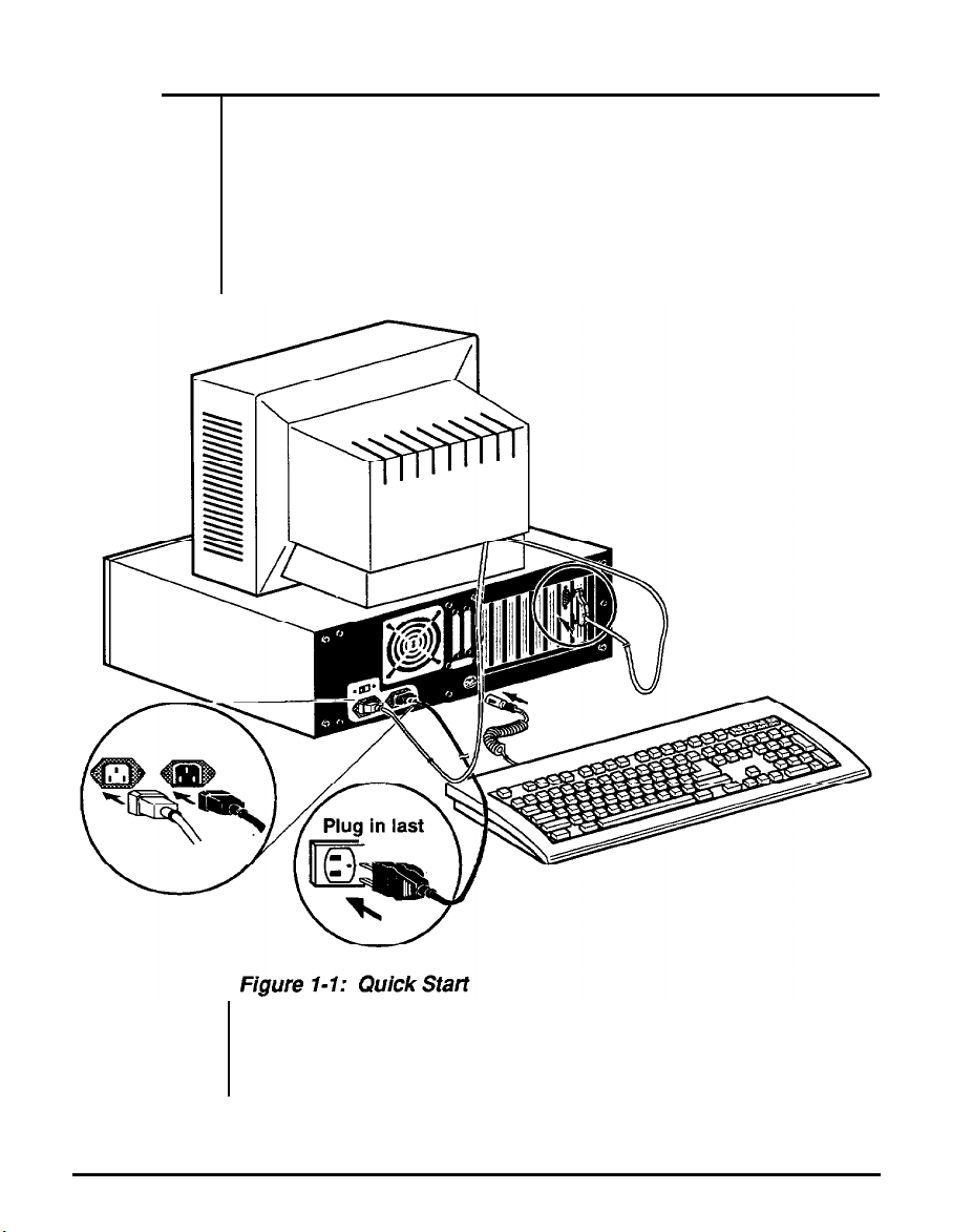
1-2 Quick Start
If you are an experienced user anxious to start using your computer,
observe the figure below to set up your personal computer. You will
still want to use this manual later as a reference book.
Note: Save all packing materials in case you need to ship your
computer.
Chapter 1: System Overview
3
Page 19

1-3 Features
•
•
•
•
•
•
•
•
•
•
•
•
•
•
Intel 80286-12 microprocessor with 80287 coprocessor op-
tional
Use of CHIP’s PC/AT-compatible chip set
Switchable between 6MHz Normal mode and 12MHz Turbo
mode by either a software switch or a hardware switch
Onboard battery backup for the CMOS configuration table
and a real-time clock
RAM subsystem of 512KB, 640KB, 1 MB, 1.5MB, 2MB,
3MB, 4MB and 5MB
Eight expansion slots -five 16 bit slots and three 8 bit slots
Sixteen-level interrupt
Seven-channel DMA for disk and special I/O
64KB legal BIOS
Four-layer mainboard
LIM 4.0 EMS support
Shadow RAM support
Choice of either 44256 DIP or 256k/l M SIMM DRAM
modules
Page/Interleaved DRAM access method support
4
Chapter 1: System Overview
Page 20

1-4 Specifications
•
CPU
•
RAM
•
ROM
•
Expansion slots
• Disk Drive(s)
• Power Size
• Options —Math coprocessor 80287-8
— 80286 microprocessor, 12MHz
— Subsystem of 512KB, 64OKB, 1 MB, 1.5MB, 2MB,
3MB, 4MB and 5MB
— 64KB legal BIOS
—Five 16 bit slots and three 8 bit slots
— Three 5.25” bays and one 3.5” bay
— 165mm X 150mm X 150mm
Chapter 1: System Overview 5
Page 21
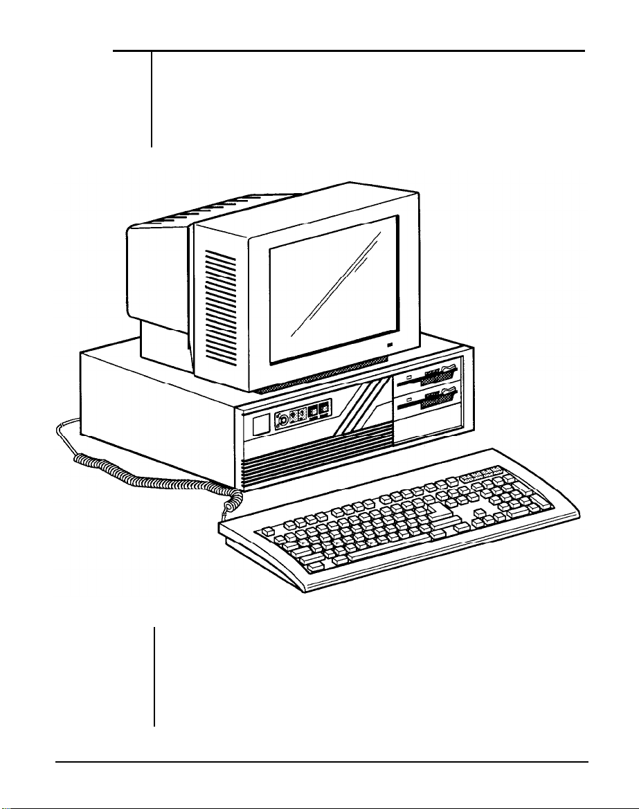
1-5 Example of a System Configuration
The basic system is pictured below. You may choose peripherals and
upgrades for the system as your needs require.
is different from the one pictured, it should operate in the same basic
manner.
Even if your system
Figure 1-2: System Configuration
6
Chapter I: System Overview
Page 22
1-6 System Unit
The system unit may house a motherboard, disk drives, a power supply
and other optional expansion cards.
Figure 1-3: System Unit Case
2 Function Lights
Chapter 1: System Overview
7
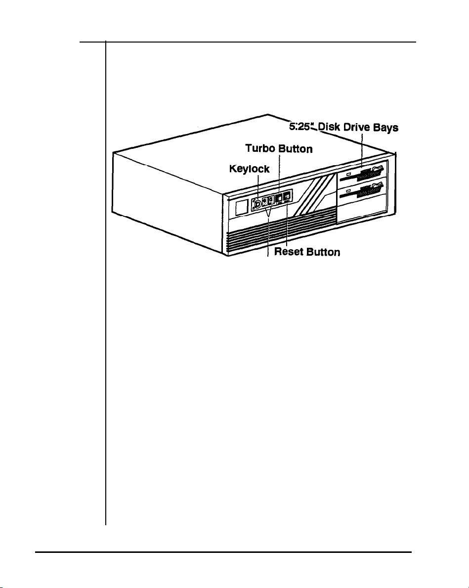
Page 23
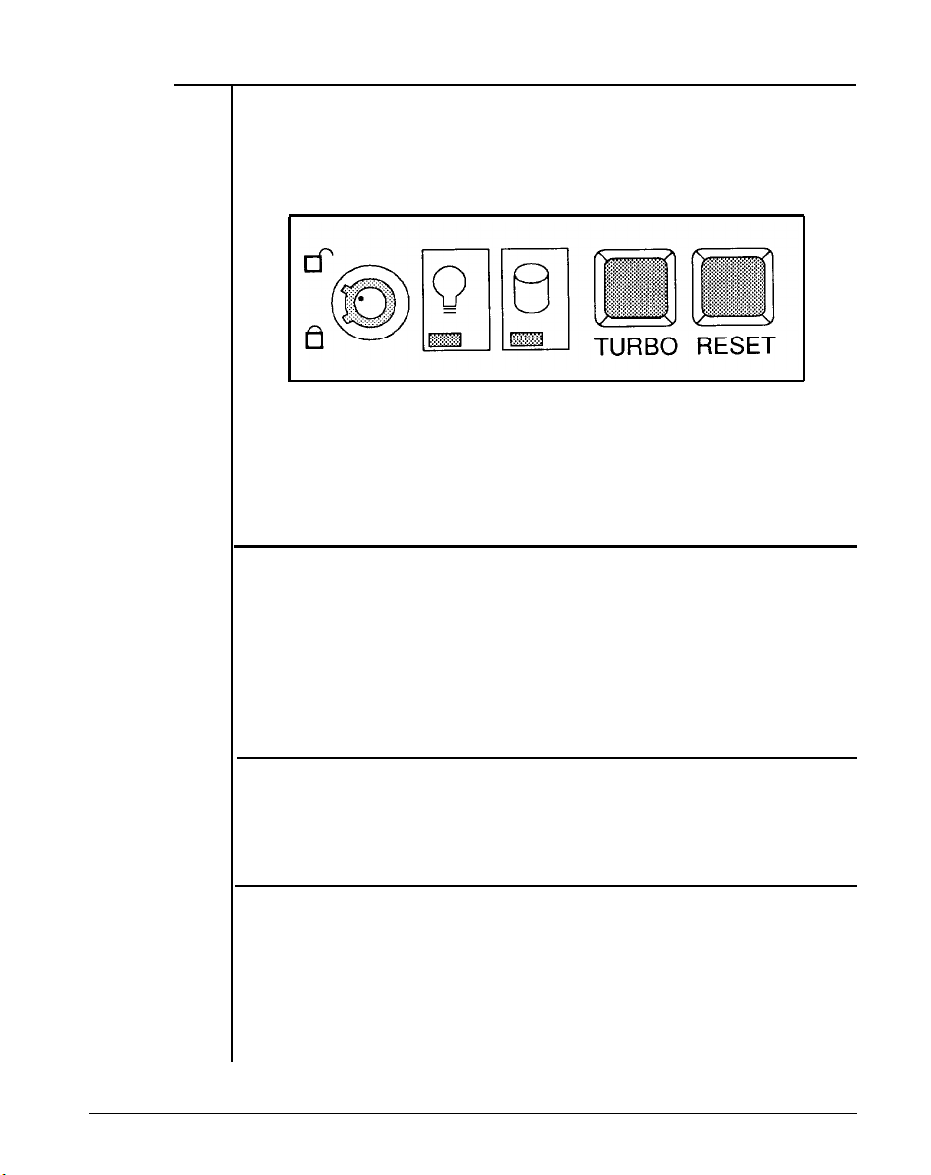
1-7 Control Panel
The control panel provides several useful functions which are explained below. You are likely to use the front panel frequently, so let’s
start there.
Figure 1-4: Front Panel
Reset Button
The reset button allows you to restart the system without turning the
power off.
If you encounter any problems while using unfamiliar software, you can
always restart quickly from the RAM test stage by pressing the reset
button. Note, however, that any data which have not been saved to
disk will be lost.
Turbo Button
The Turbo button allows you to change the running speed of the
microprocessor to accommodate software requirements.
software applications must be run at a slow clock speed.
Indicator Lights
Two lights indicate the operation status of your computer. The green
LED is lit when the power is on. The red LED comes on when the hard
disk is being accessed.
8
Chapter 1: System Overview
Some
Page 24
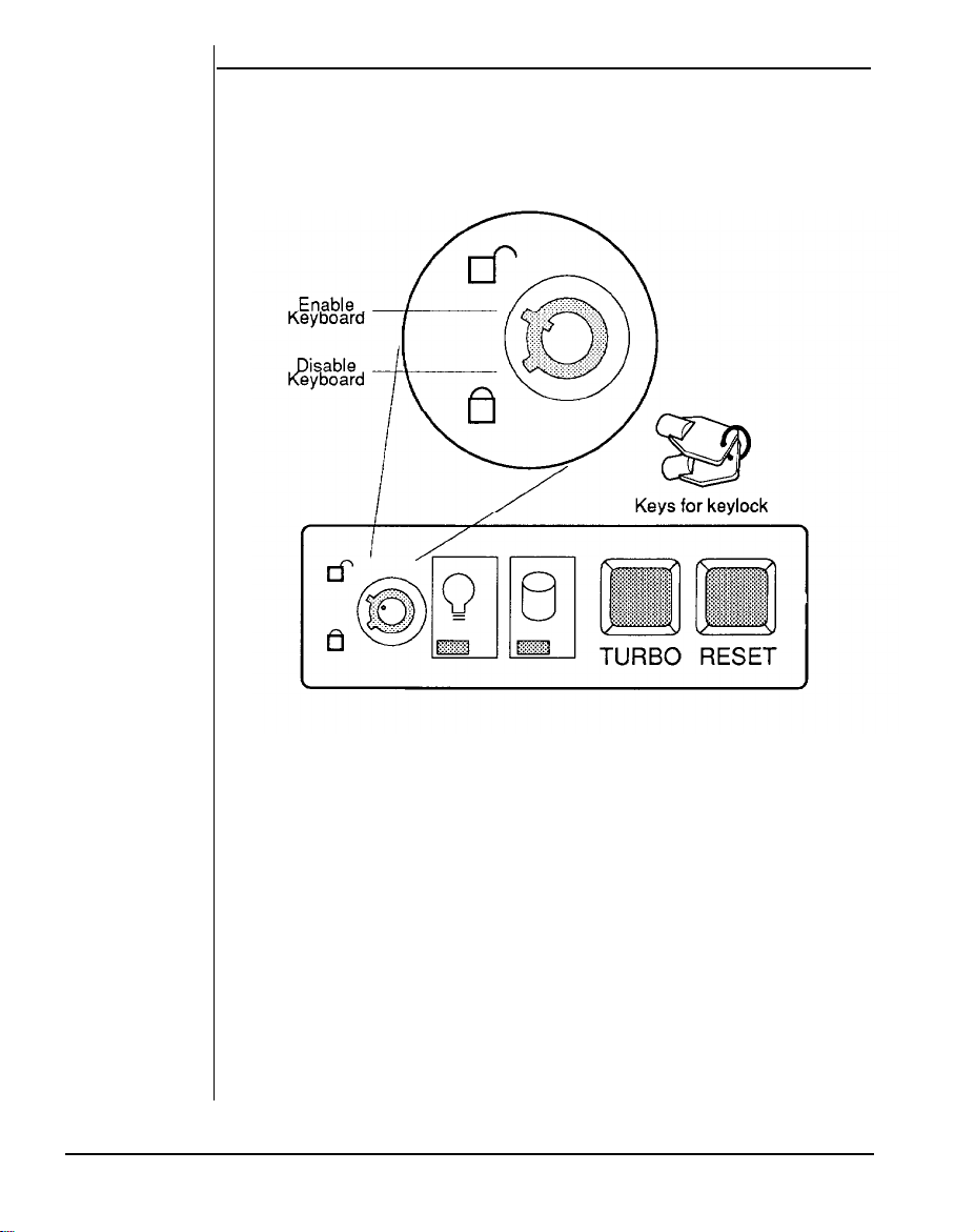
Keylock
The keylock enables or disables the keyboard.
keyboard is activated. In the lock mode the keyboard is disabled to
deny unauthorized users access to the computer.
In the unlock mode the
Figure 1-5: Keylock and Two Security-Lock Keys
Chapter 1: System Overview
9
Page 25
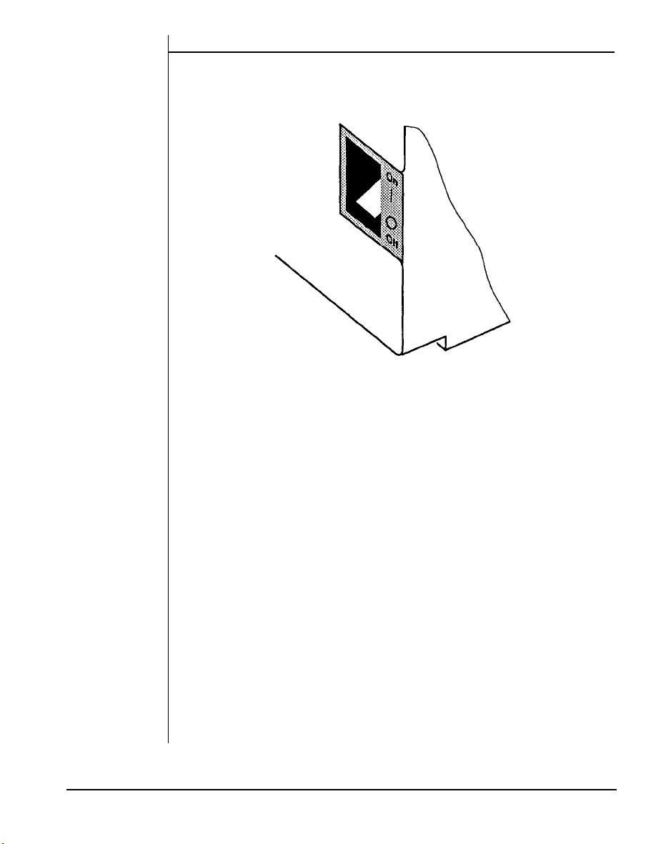
System Power Switch
The system power switch is located on the right side of the case toward
the rear.
Figure 1-6: ON/OFF Switch in OFF Position
You should always be certain that the power is turned off before
modifying the hardware configuration in any way.
10
Chapter 1: System Overview
Page 26
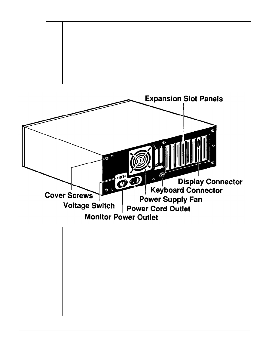
1-8 Rear Panel
The rear panel has all the connections that lead from the system unit
to external peripherals and the power source.
switches before connecting or disconnecting cables/wires!
sure that cables/wires are attached to the peripheral device first and
connect to the outlet of the system unit case later. Turn the system unit
power switch off before you plug the power cable into an electrical
outlet.
Turn off all power
En-
Figure 1-7: Rear Panel
Chapter 1: System Overview
11
Page 27
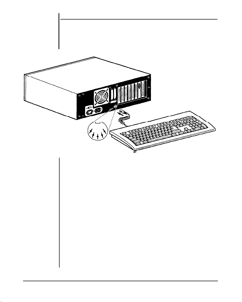
Keyboard Connector
The keyboard supplied with your system may be plugged into sockets
at the back of the case.
shown below.
Keyboard Connector
Plug the keyboard cable into the socket as
Figure 1-8: Connecting the Keyboard Cable
12
Chapter 1: System Overview
Page 28
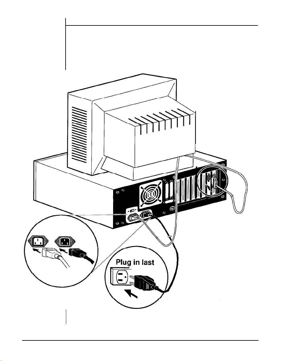
Power Cord Connector
The power supply has two receptacles: one supplies power to a
monitor; the other connects to the main power source.
Yet, if your monitor power plug does not fit the system unit’s monitor
power outlet, you should plug it into a wall electrical outlet.
Figure 1-9: System Power Cord
Chapter 1: System Overview
13
Page 29
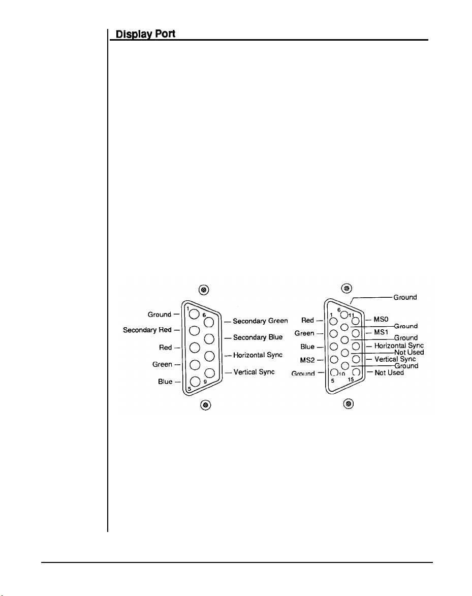
You will also need to connect your monitor to the system unit at a
female display port in one of the expansion slots as shown on the
previous page.
To attach the monitor cable to the display port, plug the cable into the
port and screw the cable connector down securely.
Your computer gives you a wide range of video options to meet your
needs.
You have a wide choice of the following video standards.
-
MGA (Monochrome Graphics Adapter) also referred to as
Hercules
-
CGA (Color Graphics Adapter)
-
EGA (Enhanced Graphics Adapter)
-
VGA (Video Graphics Adapter)
Refer to the figures below for mono and color display connectors.
Figure 1-10: Two Kinds of Display Connectors
14
Chapter 1: System Overview
Page 30
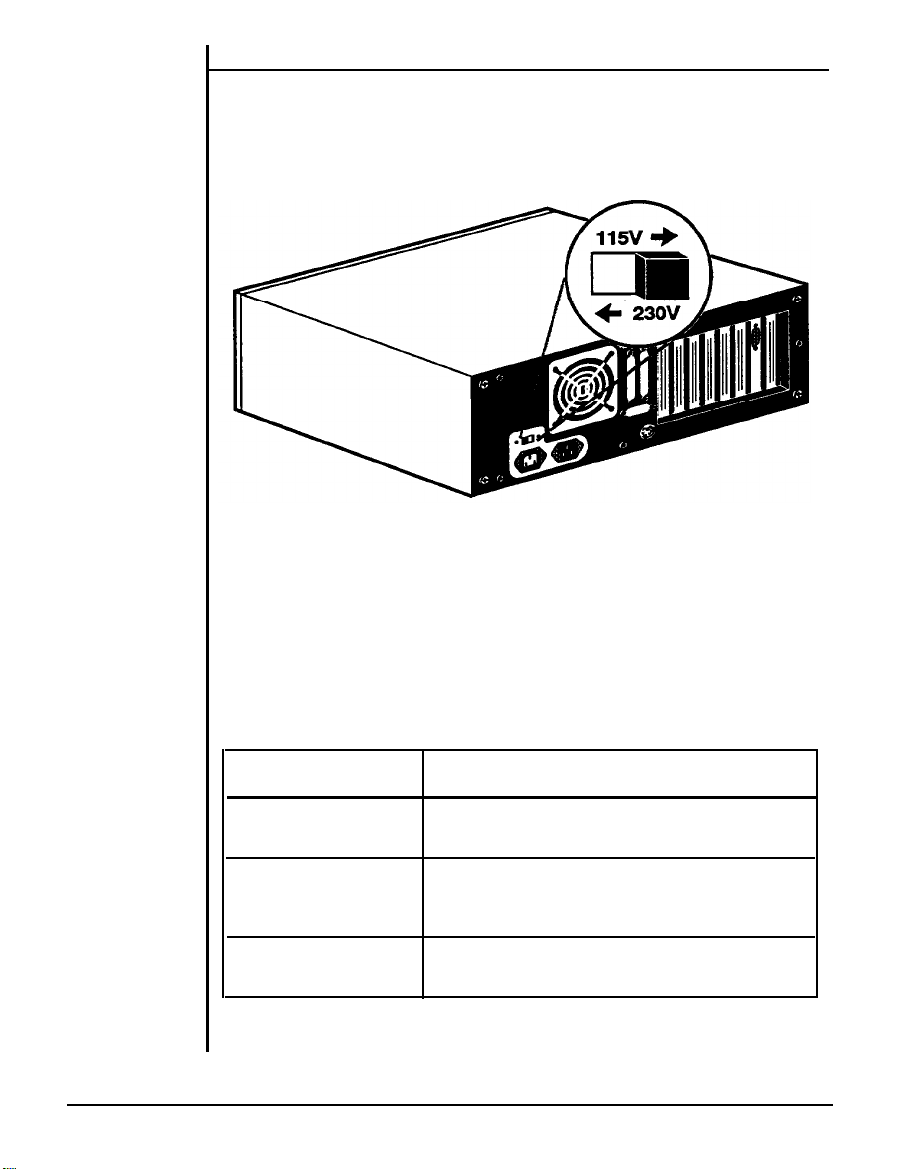
Power Voltage Setting
The
system unit can run on either 115V or 230V as indicated in Figure
1-11. The voltage setting switch is located above the monitor power
outlet. Refer to Table 1-1 for power cord specifications.
Figure 1-11: Voltage Switch
When you are using the PC in American areas, switch the voltage
selector switch to 115V and if you are in European countries, switch to
23OV.
Refer to the following table for the appropriate specification of
the
power cord used.
Power Source
Cord Specification
UL listed; SVT/SJT type; three-conductor
115v
rated 10A, 125V; < 15ft. in length
Appropriate approval listed in that
230V
230V (U.S.A. only)
specific country; three-conductor;
rated 6A, 250V
UL listed; SVT/SJT type; three-conductor;
rated 6A, 125V; <16ft. in length
Table 1-1: Power Cord Specifications
Chapter 1: System Overview
15
Page 31

1-9 Other Peripherals
To connect other peripherals (printer, modem etc.), refer to your expan-
sion card manuals or peripheral manuals to determine which ports are
to be used. Your may consult your dealer for more about the expan-
sion cards available for your system. Typical peripherals are shown as
the figure below.
Figure 1-12: System Unit Connected to Peripherals
16
Chapter 1: System Overview
Page 32

1-10 Disk Drives
Your disk drive displays different kinds of composition by installing at
most three 5.25” floppy/ hard and one 3.5” hard disk drives. You can
decide the composition according to your need. More information
about how to install disk drives may be found in Chapter 6.
Figure1-13: Installing Floppy and Hard Disk Drives
Chapter 1: System Overview 17
Page 33

Floppy Disks
With a floppy disk drive you can format and use double-sided (or
single-sided) double-density (or high-density) floppy disks.
One double-sided doubledensity 5.25” floppy disk can store up to
360KB of data One double-sided high density 5.25” floppy disk can
store up to 1.2MB of data. Besides, one standard 3.5” floppy disk can
store up to 720KB of data.
One high density 3.5” floppy disk can store
up to 1.44MB of data.
Table 1-2: Floppy Disk Specifications
Note:
•
Only high-density floppy disks can be formatted to high
capacities of either 1.2M for 5.25” or 1.44M for 3.5” floppy
disks. You may lose data if you use a low-density floppy
disk formatted for high density.
•
You can’t use a high-density disk in a low-density disk drive.
18
Chapter 1: System Overview
Page 34

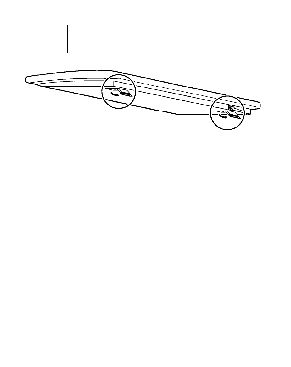
Copy Protection
A tab on the 3.5” diskette is used for protection of data. This is a
mechanical method of protecting the disk from additions, deletions and
alterations of existing data.
The figure below shows a diskette with the write protect tab. To enable
write protection, slide the tab toward the outermost position so that you
can see through the write protect hole. To disable write protection,
slide the tab in the opposite direction so that the hole is covered.
Note that write protection does not prevent loss of data from accidents
such as coffee spills, fires
and nuclear holocausts.
Copy
Protected
Unprotected
Figure 1-14: Copy Protection for a 3.5” Floppy Disk
Figure 1-1
‘5: Copy Protection for a 5.25” Floppy
‘Disk
Chapter 1: System Overview
19
Page 35

Hard Disks
Your
computer is very powerful and versatile. To make full use of all
had
its capabilities, you
your efficiency because the hard disk keeps programs and data available at your fingertips.
better use a hard disk. A hard disk can raise
Moreover, your system gives you a wide range of half-high
hard disk(s) of 3.5” or 5.25” to
meet
your
needs.
or
full-high
20
Chapter 1: System Overview
Page 36

1-11 Keyboard
Your keyboard has a set of function keys, cursor keys and a numeric
keypad. The figure below shows a typical keyboard. Refer to Chapter
4 for a more detailed description of the keyboard.
Figure 1-16:
Keyboard
Chapter 1: System Overview
21
Page 37

1-12 Maintaining Your Equipment
Read and follow carefully all the instructions and warnings in this
manual and on these products!
Only use a damp cloth to clean your system unit and
monitor case.
Do not use detergents!
Position your system unit, monitor and cables/wires away
from direct sunlight, moisture, dust, oil, and thoroughfares.
Do not submit your equipment to harsh jarring.
Ensure that all ventilation outlets are always free from
obstruction.
In the event of mechanical/power failure or damage, do not
attempt to repair the system unit, monitor/s, cables/wires.
Refer all such problems to experienced service personnel.
Ensure that the back of the system unit is at least 3” away
from anything that might obstruct the ventilation outlets and
cause overheating.
Ensure that the power source is grounded correctly. This
product is equipped with a 3-wire grounding-type plug. This
plug will only fit into a grounded power outlet.
It is recommended not to service this product yourself, as
opening and removing covers exposes dangerous voltage
areas and other risks. Refer all servicing to service persons.
22
Chapter 1: System Overview
Page 38

Chapter 2
Setting Up
Your System
Page 39

Setting Up Your System
In this chapter you will learn about:
■
n
Setting up a system is easy and takes only a short time.
has set up your system for you, you can skip this chapter. With the
system set up you are now ready to load your application software and
begin work. This chapter covers topics you are less likely to need to
know right away.
You may also skip this chapter unless you want to add to or alter your
system unit hardware yourself. It is recommended to have your dealer
or technician upgrade your system if you are a novice.
power is off before modifying the hardware configuration!
how to assemble a knocked-down system
how to upgrade your system
If your dealer
Ensure that the
Chapter 2: Setting Up Your System
1
Page 40

2-1 Motherboard
The motherboard of your computer contains an Intel@ 80286-12
microprocessor (or CPU), a 80287-8 math coprocessor socket, BIOS
chips and expansion slots. These parts of your system that you can
see and touch are called hardware.
board layout.
Below is an illustration of the
Figure 2-1: Motherboard Layout
2
Chapter 2: Setting Up Your System
Page 41

80286 CPU
The chip called a central processor unit (CPU) handles software
instructions. Your system uses an Intel 80286-12 CPU which is located at U34 on the mother board. It is an advanced, high-performance microprocessor with specially optimized capabilities for
multiple-user and multi-tasking systems. It has built-in memory protection that supports operating system and task isolation as well as
program and data privacy within tasks.
Refer to the figure below.
80286 CPU
Figure 2-2: The Location of 80286
Your system is switchable between 6MHz (Normal mode) and 12MHz
(Turbo mode) to ensure software compatibility and can be activated
with either a hardware or software switch.
at Turbo mode, you may switch to the normal speed.
Chapter 2: Setting Up Your System
CPU
If software fails to operate
3
Page 42

Math Coprocessor
If you process numeric data, a math coprocessor will make your work
more efficient .
An optional 80287 math coprocessor can be installed in socket U35 to
accelerate processing of calculation-intensive applications.
Remember that you must make sure the dotted end of the chip is lined
up with the notched end of the socket.
Refer to the illustration for
80287 math coprocessor below.
Math Coprocessor
(U35)
Figure 2-3: The Location of 80287
4 Chapter 2: Setting Up Your System
Page 43

Chips or RAM Modules Insertion
Remember that when inserting chips or Ram modules, you must make
sure that the notched or the dotted end of the chip is lined up with the
notched end of the socket. Gently push the chip into the socket, and
be careful not to bend the pins. Refer to the figures below.
Figure 2-4: Chip Insertion
Figure 2-5: RAM Module Insertion
Chapter 2: Setting Up Your System
5
Page 44

Jumper
A jumper is a kind of switch which uses a plastic cap with a metal
interior to connect (short) two pins. If a jumper needs to be left open,
you should save the cap for future use by covering only one pin of a
jumper. This has no effect on the function of the board while it keeps
the cap handy. The illustration below shows the side and top views of
a three-pin jumper in which pins two and three are shorted.
Side View
Top View
I
Pin 1
Figure 2-6: An Example of Three-Pin Jumper Setting
6
Chapter 2: Setting Up Your System
Page 45

Onboard System Memory Size
Jumpers JP1 - JP6 are used to set the RAM size you want on the
mainboard. The DIP and SIMM DRAM banks can contain from 512KB,
64OKB, 1MB, 1.5MB, 2MB, 3MB, 4MB to 5MB by means of setting
them. Refer to Figure 2-1 for the location of jumpers JP1 - JP6 and the
illustration below for RAM banks.
Figure 2-7: RAM Banks
Chapter 2: Setting Up Your System
7
Page 46

The following shows the configuration for total onboard system
memory.
Description
Using one bank or two banks (banks 0 & 1) with
either DIP or SIMM DRAM
Using three or four banks of DIP (banks 0, 1) and
SIMM (banks 2,3) DRAMS as onboard memory
Table 2-1:
Settings of Jumper JP1- JP6
S
as onboard memory
JP1 - JP6
Settings
Before setting up RAM configuration in BIOS, you must refer to the
following table to set the wait state and the page-interleave mode.
Particularly, you cannot set both 0 wait state and disabled page-
interleave mode in Turbo mode;
operate normally, even cannot display the screen.
otherwise your system cannot
In order to set both
modes normally, you should switch the button from Turbo mode to
Normal mode.
RAM access time is 120ns.
Table 2-2: Total Onboard System Memory Size
8
Chapter 2: Setting Up Your System
Page 47

Figure 2-8: 512KB Total Onboard System Memory
You may use either bank as bank 0.
Chapter 2: Setting Up Your System
9
Page 48

Figure 2-9: 640 KB Total Onboard System Memory
You may use either bank as bank 0.
Chapter 2: Setting Up Your System
10
Page 49

Figure 2-10: 1MB Total Onboard System Memory
Any bank 0 may be used with any bank 1.
Chapter 2: Setting Up Your System
11
Page 50

Figure 2-11: 1.5 MB Total Onboard System Memory
12
Chapter 2: Setting Up Your System
Page 51

Figure 2-12: 2MB Total Onboard System Memory (A)
Figure 2-13: 2MB Total Onboard System Memory (B)
Chapter 2: Setting Up Your System
13
Page 52

Figure 2-14: 3MB Total Onboard System Memory
Chapter 2: Setting Up Your System
14
Page 53

Figure 2-15: 4MB Total Onboard System Memory
Chapter 2: Setting Up Your System
15
Page 54

Figure 2-16: 5MB Total Onboard System Memory
16
Chapter 2: Setting Up Your System
Page 55

ROM BIOS Chips
To install the ROM chips, refer to the illustration below for the location
of the chip sockets on the mainboard.
Be
sure that the type of BIOS is DTK BIOS or any other of 64KB size.
Figure 2-17: Installing
ROM
Chapter 2: Setting Up Your System
17
Page 56

2-2 Installation
The time may come when you want to upgrade your system. To do so,
you may need to remove the cover of the unit. This is easily accomplished with the following tools: a small flat-blade screwdriver and
a small Philips screwdriver.
Be sure that the power to the system is switched OFF before you open
the case. Your computer interior is as below:
Figure 2-18: Unpacking Your Main System
18
Chapter 2: Setting Up Your System
Page 57
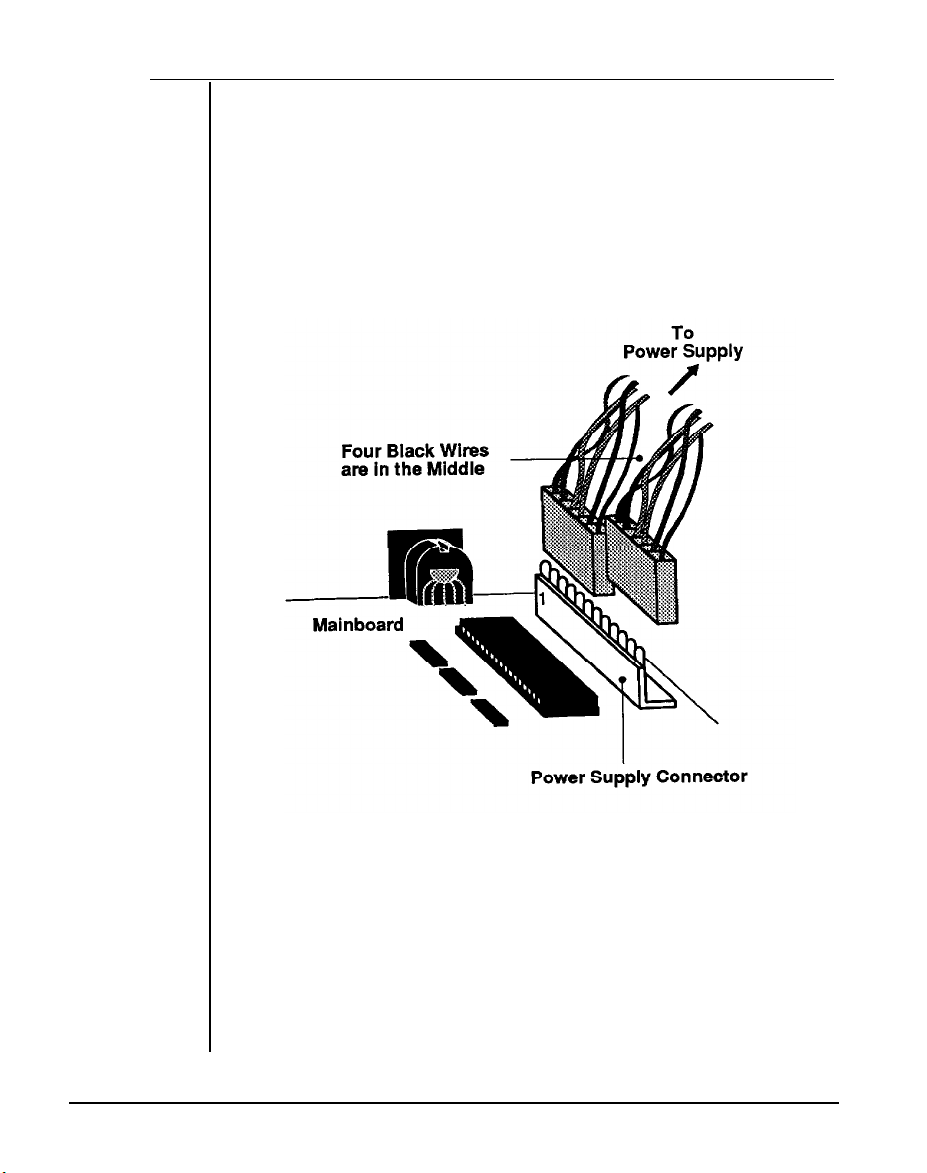
2-3
Connecting to the Power Supply
If your power supply has not been attached to your motherboard, you
may need to attach the power supply cable to the connector J8, which
is located at the lower right quadrant of the motherboard.
There are some cables on the power supply. Be sure the four black
wires of the power supply cables are located at the middle of the power
connectors. Refer to the figure below. Pin 1 is numbered in the picture
for your convenience.
Figure 2-19: Connecting to the Power Supply
Chapter 2: Setting Up Your System
19
Page 58

The pinouts for the connectors at J8 are as below.
Table 2-3: Power Supply Pinouts
20
Chapter 2: Setting Up Your System
Page 59
Operating
Your System
Page 60

Operating Your System
In this chapter you will learn:
a few MS-DOS functions
■
n
the basics of the system setup program
The software that your system will use falls into two categories.
there is the operating system, the language that tells the system what
to do. The operating system in this computer uses is Microsoft
Corporation’s MS-DOS, the world’s most widely used operating sys-
tem for PC/XT/ATs.
Next, there is the application software what you use for work and play.
Finding application software is a simple matter of going to your nearest
PC store.
Note:
This is not an MS-DOS manual. It mentions only a few of the DOS
functions available. To learn more about DOS, refer to your MS-DOS
User’s Guide and Reference manual included with your system.
First
Chapter 3: Operating Your System
1
Page 61

3-1 An Introduction to DOS
DOS stands for Disk Operating System. This is a set of commands
used to control the operations of a computer and its peripheral components. DOS makes it easy for you to use applications and create
and manage files on your computer. DOS also lets you use devices
with the computer.
Loading DOS
Loading DOS means to copy all the DOS programs into the computer’s
electronic memory. You should follow the instructions below to start
DOS.
Starting DOS when the computer is off:
l
Insert DOS disk 1 into disk drive A and close the drive lever.
l
Turn on the computer and respond to the prompts displayed
on the monitor.
Starting DOS when the computer is on:
If you don’t have a DOS disk in your disk drive when you start your
computer, you will see the following message on the screen following
the RAM test:
Non-system disk or disk error
Replace and strike any key when ready
Then, you should:
l
Insert DOS disk 1 into disk drive A and close the drive lever.
l
Press the reset button on your front panel (hardware reset)
or hold down the <Ctrl>, <Alt> and <Del> keys at the same
time (software reset) to reboot your system.
Starting DOS from your hard disk:
If you have a hard disk, install DOS on the disk. Your PC will boot
automatically whenever you turn on the power.
System Messages
Refer to your MS-DOS User’s Guide and Reference manual for information on system messages.
2
Chapter 3: Operating Your System
Page 62

3-2 DOS Operations
Following is a brief explanation of a few DOS functions.
If you want a
detailed explanation of all the DOS commands, refer to your DOS user
manual.
Starting MS-DOS
If you are using a hard disk with DOS already installed, the computer
will “boot” or start itself.
If you are using a floppy disk drive, insert the DOS system disk in drive
‘A” and switch on your computer. You will see a message similar to
the following:
Current date is Fri
Enter new date (MM-DD-YY):
01-01-1990
For the new date, key in the month, day and year, separated by
hyphens. Press <Enter>.
Time is displayed and corrected as follows:
Current time is 0 : 02 : 15.00
Enter new time: 2:20
Your computer is now booted and ready to run application programs.
Chapter
3:
Operating Your System
3
Page 63

Formatting Disk
You must format a floppy disk before it can be used.
Formatting high-density disk:
To format a high-density disk, type the following at the drive prompt:
C>Format A:
<Enter>
After your disk has been formatted, you will see the following prompt:
Format another diskette (Y/N)?
Press <N> if you do have nothing else to be formatted.
Formatting a lo w-density disk:
To format a low-density disk, type the following at the drive prompt:
C>Format A:/4
<Enter>
After your disk has been formatted, you will see the following prompt:
Format another diskette (Y/N)?
Press <N> if you have nothing else to be formatted.
4 Chapter 3: Operating Your System
Page 64

Backing up your Diskettes and Files
In order not to lose your files through disk damage or accidental
deletion it is important to back up all your files and diskettes regularly.
Backing up a diskette on a two-floppy disk drive system:
At the A> prompt type the following:
A> diskcopy a: b:
Press <Enter> and respond to the prompts on your screen.
Backing up a diskette on a single floppy disk drive system:
At the A> prompt type the following:
A> diskcopy
Press <enter> and respond to the prompts on your screen.
After your target disk has been copied, you will see the following
prompt:
Copy another diskette (Y/N)?
Press <N> if you have nothing else to be copied.
Backing up a file:
To
back up a
single file, key in the backup command and directory as
below:
A>backup <path> <filename> <drive>/A
Chapter 3: Operating Your System
5
Page 65

Deleting your Diskettes and Files
You may want to erase diskettes or unnecessary files to make room for
other data.
Erasing a diskette:
To erase a whole directory of files, type the following at the drive
prompt:
A>del *.*
<Enter>
All the files in the open directory are now erased.
Deleting a file:
To delete a single file, type the following at the drive prompt:
A>del filename.ext
<Enter>
6
Chapter 3: Operating Your System
Page 66

Finding Out What is on Your Disk
If you want to find out what files are on a disk, you can list its directory
by using the <DIR> command.
If you want to display the directory of
the disk in drive A, you would use the following command:
DIR A:
After you hit the enter key, all the file information will display on the
screen.
If you use the <DIR> command without a drive letter, MS-DOS lists the
directory of the disk which was most recently accessed.
There are three ways to stop the screen from scrolling.
l
pressing the
l pressing <Pause>
l
typing DIR/P to see one screen each time
<CTRL>
and the <S> keys simultaneous
Chapter 3: Operating Your System
7
Page 67

3-3 Hard Disk Drive Format
A hard disk must be formatted before it can be read from or written to.
If
your hard disk requires this, you should carry out the following steps.
Step 1
—
Preformat
The preformat utility is supplied by the system BIOS. You can press
<Esc>
key quickly just after the RAM test to enter the SETUP program.
Choosing item 2 from the initial screen to preformat hard disk. See
Figure 3-l.
Step 2 — Partition
This process creates DOS partitioning on a preformatted hard disk
five. The DOS command “FDISK” handles this partitioning process.
Insert your DOS diskette in drive A and type a: to get A prompt. Then
type:
A> FDISK
The “FDISK” command displays a serial of menus to help you partition
(our hard disk for MS-DOS, With the “FDISK” command, you can:
•
create a primary partition,
•
create an extended partition,
•
change the active partition,
•
delete an partition,
•
display partition data, and
•
select the next fixed disk drive for partitioning on a system
with multiple fixed disks.
If your hard disk is 4OMB, you may have partitions of up to 33MB in
size. 33MB is the maximum space for a partition allowed by DOS.
For more information about how to use creating DOS partition, see
Appendix D in MS-DOS User’s Guide and Reference.
8
Chapter 3: Operating Your System
Page 68

Step 3 — Format
The DOS command “Format” verifies the media and moves the system
file onto the hard disk drive. The command should be keyed in as:
A> FORMAT C:/S
If you have two partitions, you have to format D in DOS prompt. The
command should be keyed in as:
A> FORMAT D:
If you want to use the partition 1 (drive C) to start DOS, you have to
specify the /S option when formatting the disk. You can use this
system disk to boot your system later.
Note that you don’t need to perform this procedure if you want to use
new partitions for other operating systems like Xenix, Novell or Unix.
Refer to their manuals for details.
Chapter 3: Operating Your System
9
Page 69

3-4 Helpful Hints
The following may save you some time or help you as you use your
computer.
Make copies of your diskettes regularly.
To make sure that a command works, you should:
—
Check your typing (make sure you don’t confuse \ with /).
—
Have the correct diskette in the drive.
—
Check the contents of the diskette with the DIR command.
—
Specify the correct diskette drive.
—
Remember to include the colon (:) when specifying the
name of a drive.
—
Spell the filename correctly
—
Use the appropriate extension (such as *.DOC or *.EXE)
Refer to the DOS Reference for additional information if a
command still doesn’t work.
Print contents of a disk (if you have a printer) and keep the
list with the diskette.
All commands (except DISKCOPY and DISKCOMP) are
files that will work on both diskettes and hard disk drives.
The date and time shown with each directory entry are the
date and time of the last addition or change
to
that file. The
date and time are not changed during a COPY or a DISKCOPY.
10
Chapter 3: Operating Your System
Page 70

3-5 System Setup Program
A system setup program is included in your BIOS on the motherboard.
The setup program is used to key in the configuration you want for your
system. Specifically, you can set the date, time, base memory, expansion memory, number of floppy and hard disk drives and display
configuration as well as get information on hard disk types.
Your system BIOS is fully compatible with IBM BIOS. In addition, many
special functions are supported like:
l
a low-level fixed disk format utility
l
three system utilities (a calculator, a hard disk park, and a
timer)
l system password
l
user-defined hard disk types
l NEAT chip set
The setup program is simple to be used. It is extremely important that
you respond correctly to the prompts about your computer.
The following will guide you through the setup program.
For more
information about the setup program, refer to your BIOS manual.
Chapter 3: Operating Your System
11
Page 71

Entering the Setup Program
There are two ways to enter the setup program: by pressing <F1> or
by pressing <Esc> .
1. Pressing <F1> to Enter the Setup Program
You will need to press <F1>, to enter the setup program in the following
situations:
•
when your computer is turned on for the first time
•
when the rechargeable battery is dead
•
when the hardware configuration is changed
If the battery for CMOS chip is dead or the system configuration does
not match your actual hardware configuration, you will have to recon-
figure your system, The computer will give you this screen message:
Press the Fl key to enter the setup program or
press any other key to continue
Under the above three conditions, pressing <F7> will automatically
start the setup program.
Under any conditions within DOS, you can use the DOS DEBUG
command as follows:
A> DEBUG
-g=F000:FF60
This command will start the setup program.
Chapter 3: Operating Your System
12
Page 72

2. Pressing <ESC> to Enter the Setup Program’
If you want to set up special functions provided by BIOS or reconfigure
your system, you will need to enter the setup program. After starting
your computer, press the <Esc> key quickly before the RAM test
finishes. If you miss the chance to do so, reset your system and repeat
the above procedures to enter the setup program. Before the setup
program appears, the following message will appear on the screen:
SETUP utility will be starting
When the system self test is completed, the setup program will take
over.
Once you have entered the setup program, you will see the following
initial screen:
(C) COPYRIGHT DATATECH ENTERPRISES CO., LTD 1990.
ROM SETUP PROGRAM VERSION 2.0
ALL RIGHTS RESERVED.
1. SET UP SYSTEM CONFIGURATION.
2. PREFORMAT HARD DISK.
3. SET UP BUILT-IN UTILITY.
4. SET UP PASSWORD.
5. SET UP USER-DEFINED HARD DISK TYPE.
6. SET UP NEAT CHIP SET.
9. QUIT SETUP PROGRAM.
CHOOSE ITEM NUMBER : [1]
Figure 3-1: Initial Screen
Chapter 3: Operating Your System
13
Page 73

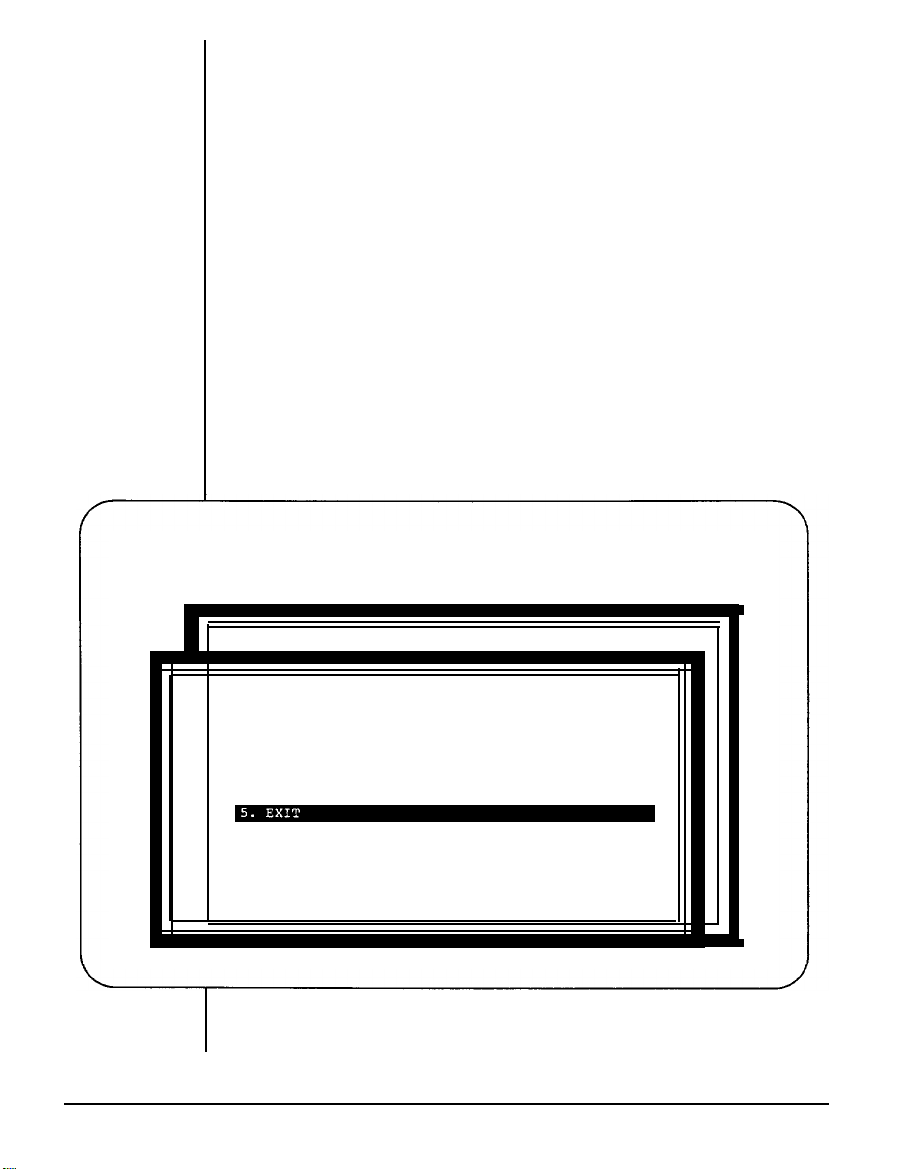
Running the Setup Program
The menu of the setup program highlights the selected command. You
can use the up < › > and down < œ > arrows to select the desired item.
Pressing the enter key
<
8
> confirms your selection or enters the next
screen. If the option on the screen does not match your configuration,
you have two ways to make modifications. You may either highlight
selections and press
and right <
"
<
8
>
to enter the command or use the left
<
!
>
> arrows to show different options and select from them.
If you want to exit a current screen, you may press <Esc>
or select
the exit item of the screen.
The following are some examples of setup program screens you will
see in using the program.
14 Chapter 3: Operating Your System
Page 74

1. Setting Up System Configuration
If you choose item 1 from the screen on the previous page to configure
your system, the following will appear:
(C) COPYRIGHT DATATECH ENTERPRISES CO., LTD 1990.
ROM SETUP PROGRAM VERSION 2.0
ALL RIGHTS RESERVED.
SET UP SYSTEM CONFIGURATION
1. CURRENT DATE : [04-26-1990]
2. CURRENT TIME : [05:30:00]
3. COPROCESSOR : [
4. BASE MEMORY :[ 640 KB ]
5. EXTENDED MEMORY : [ 1280 KB ]
6. DISKETTE DRIVE A : [ 1.2 M ]
DISKETTE DRIVE B : [ NO
7. FIXED DISK TYPE C : [ 40 / MFM ]
FIXED DISK TYPE D : [ NO / NONE ]
8. PRIMARY DISPLAY CARD : [
9. EXIT
-------------------------------------------------------------
›œ ›œ
CHOOSE ITEM NUMBER : [l]
:CHANGE ITEM
•ž •ž
1 ]
:MODIFY
]
8 8
:ACCEPT
MGA ]
Figure 3-2: “Set Up System Configuration ” Screen
Once you have entered all appropriate information and exited by
choosing item 9, you will be asked to confirm that the configuration
data are correct.
If at a later date you alter the configuration of your system, you will
need to go through the program again and make the appropriate
changes.
Chapter 3: Operating Your System 15
Page 75

2. Preformatting Hard Disk
If you want to preformat your herd disks, reenter the setup program by
pressing <Esc>, end select item 2 on the initial screen. The program
will then proceed es below:
(C) COPYRIGHT DATATECH ENTERPRISES CO., LTD 1990.
ROM SETUP PROGRAM VERSION 2.0
ALL RIGHTS RESERVED.
1. SET UP SYSTEM CONFIGURATION.
3.
4.
5.
6.
9.
SE
SE
SE
SE
QU
CH
PREFORMAT HARD DISK
1.
DRIVE TO PREPORMAT (C,D)
2.
INTERLEAVE RATE (1,2,3)
3.
BUILD BAD TRACKS TABLE
4.
BEGIN TO PREFORMAT.
SELECTION [5]
-------------------------------------------------.
›œ ›œ
:CHANGE ITEM
: [ 0 ]
8 8
:ACCEPT
: [
C
:[ 3 ]
Figure 3-3: “Preformat Hard Disk” Screen
]
16 Chapter 3: Operating Your System
Page 76

3.
Setting Up Built-in Utilities
Three system utilities, a calculator, a hard disk park, and a timer, are
in
your system BIOS. These utilities are enabled by the setup pro-
Note that these utilities can be used in the 80-column text
gram.
display mode only.
The calculator and the hard disk park can be used if you press <Ctrl>,
<Alt>, and <5> (on the key pad). Pressing <Esc> will exit these
utilities.
The following is the figure for the calculator.
Figure 34: Calculator
Chapter 3: Operating Your System
17
Page 77
4. Setting Up Password
Selecting item 4 in the initial setup menu will lead you to set up a
system password. A password can deny unauthorized users access
to the computer. You can key in a password with a maximum of seven
alphanumeric units.
You may press
<F1>
to see the present password status.
5. Setting Up User-Defined Hard Disk Type
If none of the drive types (1-47) match the fixed disk drive specifications you have, select item 5 in the setup menu to set a user-defined
hard disk type.
6. Setting Up NEAT Chip Set
Choose item 6 in the setup menu to select a chip set configuration.
The screen will show as below:
(C) COPYRIGHT DATATECH ENTERPRISES CO., LTD 1990.
NEAT CHIP SETUP CONFIGURATION
1. SHADOW RAM
2. DRAM WAIT STATE
3. PAGE/INTERLEAVE : [ DISABLE ]
4. EMS INSTALLED : [ DISABLE ]
CHOOSE
--------------------------------------------------------------
ITEM
›œ ›œ
:CHANGE ITEM
Figure 3-5: “NEAT Chip Setup Configuration” Screen
18
Chapter 3: Operating Your System
ROM SETUP PROGRAM VERSION 2.0
ALL RIGHTS RESERVED.
: [ SYSTEM OFF , VIDEO OFF ]
: [ ZERO WAIT STATE ]
NUMBER : [5]
8 8
:ACCEPT
Page 78

Chapter 4
Keyboard
Page 79

Keyboard
In this chapter you will learn:
■
the basics of your keyboard and its functions
■
how to adjust your keyboard angles
A computer keyboard sends messages from you to the computer. It
has:
•
QWERTY keys
•
Function keys
•
Cursor control keys
•
A numeric keypad
•
Special keys
•
Keyboard indicator lights
Chapter 4: Keyboard
1
Page 80

4-1 Keyboard Layout
Currently several of keyboard styles are available for PC/AT/XT compatible computers. The most popular are the PC keyboard, the PC/AT
keyboard, and the enhanced keyboard. Figure 4-1 below illustrates
the basic layout of a typical enhanced keyboard.
Function Keys
QWERTY
Key Area
Figure 4-1: Keyboard Layout
Special Keys
Cursor Control Numeric
Keys
Keyboard
lndicator Lights
Keypad
2
Chapter: 4: Keyboard
Page 81

4-2 Getting Acquainted with Your Keyboard
Before you begin using your computer, you should become familiar
with some keyboard functions. Your keyboard is divided into six
sections. Refer to the previous page for the layout. The following
gives an explanation of these keys.
Function Keys
These are located on the left or at the top of the keyboard.
Function
keys have specially defined uses preassigned by the software you use.
They are used independently or in combination with other keys.
Figure 4-2: Function Keys
Numeric Keypad
This is located on the right of the keyboard. At the center of the keypad
are nine numeric keys. These keys are used to move the cursor as
well as to enter numbers when either the Caps Lock key or Num Lock
key is pressed. Refer to the figure below:
Figure 43: Numeric Keypad
Chapter 4: Keyboard
3
Page 82
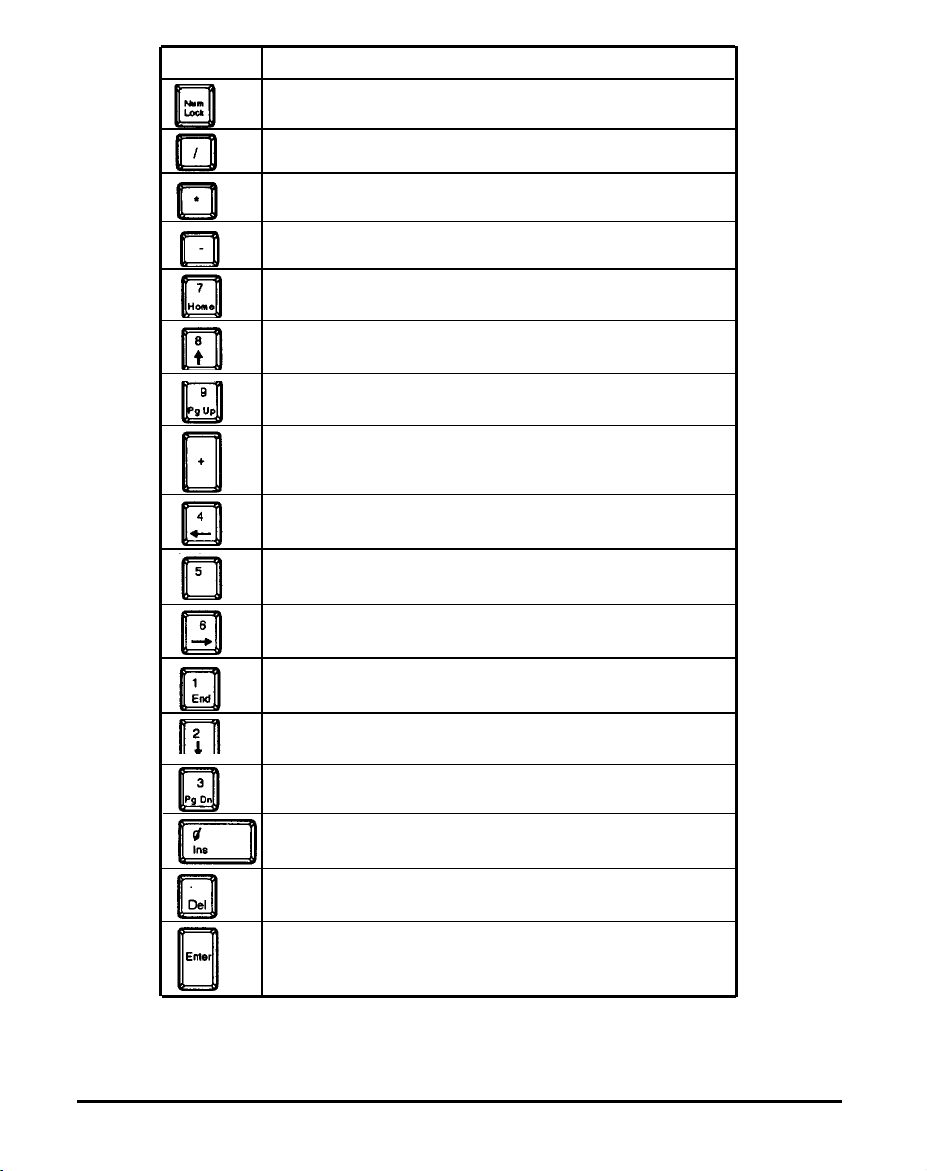
Keys
Function
Turns on and off the numeric mode on the numeric keypad
Used for division operations.
Used for multiplication operations.
Used for subtraction operations.
Activating Num Lock makes 7 operative.
Home returns cursor to the beginning of the line it is on.
Activating Num Lock makes 8 operative.
Otherwise the up cursor key is active.
Activating Num Lock makes 9 operative.
Otherwise page up is active.
Used for addition operations.
Activating Num Lock makes 4 operative.
Otherwise the cursor key is activated.
Activating Num Lock makes 5 operative.
Activating Num Lock makes 6 operative.
Otherwise the cursor key is activated.
4
Chapter: 4: Keyboard
Activating Num Lock makes 7 operative. Otherwise
end moves the cursor to the end of the line it is on.
Activating Num Lock makes 2 operative.
Otherwise the cursor key is activated.
Activating Num Lock makes 3 operative.
Otherwise page down is activated.
Activating Num Lock makes 0 operative. Otherwise the key
functions to insert characters at the position of the cursor.
Used for decimal points. Otherwise it deletes characters
where the cursor is positioned.
Enters commands or inserts invisible paragraph character:
Table 4-1: Function of Numeric Keypad Keys
Page 83

Mode Indicator Lights
In addition to the character, number and control keys, every keyboard
has three lights that indicate the typing mode. These lights and their
iunctions are explained as follows:
Figure 4-4: Indicator tights
Caps Lock
When this light is on, characters are in uppercase mode.
Num Lock
When this light is off, the cursor-control function of the numeric keypad
is disabled and the numeric mode is activated.
Scroll Lock
When this light is on, text can be scrolled without moving the cursor.
Chapter 4: Keyboard
5
Page 84

Special Keys
Below are some special keys on your keyboard.
Figure 4-5: Special Keys
Check out the above key functions in the table below and in Table 4-1.
Keys
Pressing this key together with the shift key will print all
data on the screen.
With Scroll Lock activated, you can move text vertically
in line units.
Pressing this key halts the current operation; pressing it
again allows the operation to continue.
Moves the cursor for corrections, but the line
is not deleted from memory.
Skips to new line.
Used with alphanumeric keys to enter BASIC key words.
Used with another key to execute a command.
Function
Table 4-2: Functions of Special Keys
6
Chapter:
4:
Keyboard
Page 85

QWERTY Keys
These are the same keys which are used on a typewriter.
Figure 46: QWERTY Keys
Keys Function
Performs a tab function similar to that of a typewriter.
Changes lowercase letters to capitals.
Moves cursor back one space and erases characters.
Pressing this key activates uppercase letters;
pressing it again activates lowercase letters.
Table 4-3: Functions of Special QWERTY Keys
Chapter 4: Keyboard
7
Page 86

Cursor Keys
These keys move the cursor in the indicated direction.
Figure 4-7: Cursor Keys
Key Combinations
The keys shown below have special functions when pressed simultaneously.
Table 4-4: Special Functions
8
Chapter: 4: Keyboard
Keys
Function
Both keys used together stop a program
while it's running. Pressing any key
again allows you to continue.
Both keys used together interrupt a
program while it’s running and identify
line where it stops.
There three keys reset the system so that
the machine is at the RAM test stage.
Page 87
4-3 Keyboard Tilt Adjustment
Under the rear of the keyboard are two small legs that can be pulled
out or pushed in to change the keyboard angles to suit you.
Figure 4-8: Adjustment of Keyboard Angles
Chapter 4: Keyboard
9
Page 88
Troubleshooting
Page 89

Troubleshooting
In this chapter you will learn about:
■
the basics of how to solve software/hardware problems
when to get technical help for your computer
■
Your computer has been designed to last for years of optimum performance. But if some problems do occur, more likely than not you will be
able to solve them by referring to this chapter.
No matter whether you are a new or experienced user, you should
become familiar with the material in this chapter.
tions of computer problems and how to solve them, you are urged to
buy personal computer troubleshooting books from your nearest
hardware or software dealer.
For detailed explana-
Chapter 5: Troubleshooting
1
Page 90

5-1 Command Problems
Often what appears to be a big problem is in fact just a matter of a small
oversight. Before taking your computer to the shop for major surgery,
check the following items.
❑
Make sure that all devices (computer and peripherals)
have power and are turned on.
❑
If you encounter a problem while you are working, stop
what you are doing immediately.
❑
On paper, make notes of what is happening. List the
actions you have taken and the responses from the
computer. You may want to print a copy of the screen by
using the <Shift> + <PrtSc> keys combination.
❑
Use the diagnostic software on your computer. Try to
find out the conditions under which the malfunction occurs. Try also to isolate where the problem is occurring.
Is it with a certain software program or with your
hardware? If the problem is with software, you should
probably talk to your software dealer. If the problem is
with the hardware, try to narrow down the source of the
problem. Is it your disks or disk drives? Keyboard?
Printer? Screen?
2
Chapter 5: Troubleshooting
If some messages appear on the screen, refer to your
❑
MS-DOS manual for an explanation of the message. You
may want to write down the message or print it out with
the <Shift> + <PrtSc> key combination. Problems (ex-
cept blackouts) can be avoided if you run your system on
a dedicated electrical line. That is, ensure that your
computer and peripheral electric cords are not shared by
other appliances such as a refrigerator or air conditioner.
Also, it is highly advisable to purchase a surge suppres-
sor. This is a set of electric sockets enclosed in a single
housing. A surge suppressor prevents sudden pulses of
high electric power (spikes) from damaging the computer. This appliance is inexpensive and can be purchased at any computer or electronic hardware store.
Page 91

Are you using a startup disk?
❑
Is your disk formatted?
❑
Is the system configuration correct?
❑
❑
If you have gone through the above checklist and your system still does
not function properly, check the following pages. Thefollowing instruc-
tions will help you solve some common problems. However, you
should be aware that other problems might stem from system software,
applications or other peripherals.
Are all the external and internal connectors are connected well?
Make sure that you are running software compatible with
❑
your display port, because some software programs can
only run on the MGA display mode.
Is the power fuse burned out?
❑
Chapter 5: Troubleshooting 3
Page 92

5-2 System Error Messages
Basically there are three levels of system error messages that you
might see displayed on your computer. These are related to the
software you use. The following are the ones most commonly encountered.
Software error messages are a result of:
•
Software lockup;
cursor will not move. When this happens, remove your application program from the disk drive (unless a hard disk is
used) and reboot your computer. If the problem persists,
contact your nearest software dealer.
•
Software crash;
text on the monitor or the cursor locks up. Try to reboot the
computer. If the problem persists, you will need to contact
the software dealer from whom you purchased the package.
He/she should replace the package, depending on the ser-
vice contract, or have it repaired.
Hardware error messages:
the application becomes stuck and the
the application suddenly displays garbled
These messages are related to the computer’s internal components,
your monitor, mouse, or printer. Hardware problems are usually ones
that the user cannot solve alone. Professional services are therefore
required.
Error messages generated by MS-DOS, BASIC or other
high-level applications:
These messages relate to problems due to incorrect use or malfunction of a high-level application under which you might run your
software. It is still advisable to contact your software dealer for assistance with such problems.
Consult your dealer if you have any questions about troubleshooting.
4
Chapter 5: Troubleshooting
Page 93

Examples of System Error Messages
System crash
The cursor cannot be moved and does not respond to the keyboard.
This could indicate a software crash. Mark where you are in your
document. Reboot your system and reload your software. Scroll the
cursor to where you last saved your data. Retype the information up
to where the cursor could not be moved. Enter the rest of the data. If
the cursor continues to function normally, the problem was probably
caused by accidently pressing the wrong key. If the problem occurs
again, go over the same procedure.
If the problem persists, contact
your software dealer.
System does not boot
This can be caused by defective hardware or a faulty system disk.
Turn off your computer and try again. If unsuccessful, try using your
backup system disk because your working disk may be damaged. If
problem persists, you might have a hardware problem. You should
the
contact the dealer from whom you purchased your computer.
Monitor displays garbled, unrecognizable characters on the
screen
This usually indicates the monitor is set to an incorrect baud rate. Ask
your computer dealer the correct baud rate for the computer’s output
board. Locate the baud rate switches on your monitor and reset the
baud rate.
Chapter 5: Troubleshooting
5
Page 94

5-3 System BIOS Error Messages
ROM BIOS Checksum Error
— Indicates an invalid ROM BIOS failure.
8254 Error
— Indicates a 8254 timer controller failure.
8237 Error
— Indicates a 8237 DMA controller failure.
74612 Error
— Indicates a 74612 page register failure.
8259 Error
— Indicates a 8259 interrupt controller failure.
8742 Error
— Indicates a 8742 controller failure.
Check Battery
— Indicates a system backup battery disconnection or
power loss.
RTC Checksum Error
— Indicates that the system memory refresh function does
not work.
Refresh lndicator Error
Base 64K Memory Error
FDC Error User Check
FDD Seek Failure
6
Chapter 5: Troubleshooting
— Indicates that the system memory refresh does not work.
— Indicates that the system’s first 64K memory does not
work.
—
Indicates that the floppy diskette controller does not work.
— Indicates a failure of the floppy diskette drive ‘seek
operation.
Page 95

Keyboard Error User Check
—
Indicates the disconnection of the keyboard from the sys-
tem or a keyboard device failure.
Parity Error but Segment not Found, Press any Key to Continue
—
Indicates that the NMI circuit has detected a RAM parity
error.
System Memory Mismatch, Run SETUP
—
Indicates a mismatch of memory size in the CMOS RAM
as well as or-board. You need to run the setup program.
Display Card Mismatch, Run SETUP
— Indicates a mismatch of a record typed in the CMOS
RAM as well as onboard, You need to run the setup
program.
Chapter 5: Troubleshooting
7
Page 96

Appendix
Page 97

Appendix
This chapter provides:
n technical information
jumper settings in your system
n
n
information on moving your computer
This manual is not a technical reference manual; however-this chapter
provides some technical information about your system. If you need
more information, you can go to a technical library or bookstore to find
technical reference books.
Chapter 6: Appendix
1
Page 98

6-1 Installing Disk Drives
Up to three 5.25” floppy/hard disk drives and one 3.5” hard disk drive
may be installed in the system unit. Installation of a hard disk drive is
essentially similar to that for a floppy disk drive.
You may sometimes want to add to or exchange your floppy or hard
disk drives. Be certain to refer to the manuals for both the disk drive
and the controller card for any additional specific information.
In order to begin the installation, you should open the system unit case
as described on Figure 2-18. Then, refer to the two steps for fastening
disk drives and connecting cables on following pages.
However, if you want to remove disk drives, you would just reverse the
procedures to meet your needs.
2
Chapter 6: Appendix
Page 99

Step 1: Fastening Disk Drives
5.25” Floppy/Hard Disk Drives:
To install a 5.25” floppy or hard disk drive, follow the procedures below.
•
Screw the metal guides to the disk drive as shown below.
Figure 6-1: Screwing a 5.25" Disk Drive
•
Slide the back end of the disk drive first into the disk drive
bay.
•
Screw the disk drive to the disk drive bay as shown below.
Figure 6-2: Fastening 5.25” Disk Drives
Chapter 6: Appendix
3
Page 100

3.5” Hard Disk Drive:
Your 3.5” disk drive must be a hard one, because it is a hidden style.
It
cannot be slidden into the disk drive bay directly from the front panel
as
a 5.25” disk drive. It must always be installed inside the system unit
case. Refer to the procedures below.
•
Screw the lower metal guide to the disk drive as show below.
Figure 6-3: Screwing a 3.5” Hard Disk Drive
•
Put it in the 3.5” disk drive bay by hanging it on the two
hooks which are located on the left side of the 5.25” disk
drive bays.
•
Fasten it to the chassis by screwing. Refer to the figure.
4
Chapter 6: Appendix
Figure 6-4: Fastening the 3.5” Hard Disk Drive
 Loading...