

Page 1
SERVICE MANUAL
A4 monochrome Laser Printer
EPSON AcuLaser M2000D
M2000DN
M2010D
M2010DN
Page 2

Notice:
The purpose of this manual is to provide the product knowledge and the technical information required for repair or maintenance of EPSON AcuLaser M2000D/M2000DN/
M2010D/M2010DN.
All rights reserved. No part of this manual may be reproduced, stored in a retrieval system, or transmitted in any form or by any means electronic, mechanical, photocopying, or
otherwise, without the prior written permission of SEIKO EPSON CORPORATION.
This manual contains information and sensitive matters, special care should be taken when handling the manual.
The contents of this manual are subject to change without prior notice as a result of continuing improvements to the product’s performance and functions.
Some of the descriptions or the appearance of some parts in this manual may differ from those on an actual product.
Other product names used herein are for identification purpose only and may be trademarks or registered trademarks of their respective owners.
EPSON disclaims any and all rights in those marks.
Copyright © SEIKO EPSON CORPORATION 2008.
Imaging Products CS, PL & Environmental Management
Page 3
Manual Configuration
Indicates an operating or maintenance procedure, practice or
condition that, if not strictly observed, would result in injury or loss
of life.
This manual consists of the following seven chapters:
CHAPTER 1 PRODUCT DESCRIPTIONS
Describes the main features, basic specifications, consumable products,
periodic replacement parts, and controller interface of the product.
CHAPTER 2 OPERATING PRINCIPLES
Describes each mechanism configurations and explains fundamental
operating principle of major components including the control system.
CHAPTER 3 TROUBLESHOOTING
Describes the troubleshooting procedures that can help you diagnose and
resolve problems. The problems are sorted by displayed error codes and
phenomena of abnormal image output.
CHAPTER 4 DISASSEMBLY/ASSEMBLY
Describes the step-by-step procedures for disassembling and assembling
of the product.
CHAPTER 5 ADJUSTMENT
Describes the settings and the adjustments to be performed during the
maintenance work.
CHAPTER 6 MAINTENANCE
Describes preventive maintenance procedures.
CHAPTER 7 APPENDIX
Provides the additional information such as panel operations, connector
pin layouts, parts list, and exploded diagrams for reference.
CHECK
P O I N T
Indicates an operating or maintenance procedure, practice or
condition that, if not strictly observed, could result in injury or loss
of life.
Indicates an operating or maintenance procedure, practice or
condition that, if not strictly observed, could result in personal
injury or may cause damage to, or destruction of equipment.
Indicates a prohibited action during maintenance work.
Indicates a mandatory action during maintenance work.
Indicates an operating or maintenance procedure, practice or
condition that is necessary to accomplish a task efficiently.
Provides additional information that is related to a specific
subject, or comment on the results achieved through a previous
action.
Indicates a product reassembly procedure, practice or condition
that must be executed in accordance with the specified standards to
maintain the product’s quality.
Symbols Used in this Manual
Various symbols are used throughout this manual either to provide additional
information on a specific topic or to warn of possible danger present during a
procedure or an action. Be sure to read and understand the information with these
symbols.
ADJUSTMENT
REQ U IRED
Indicates an operating or maintenance procedure, practice or
condition that must be executed in accordance with the specified
standards to maintain the product’s quality.
Page 4

Safety
Safety-related Symbols
Indicates an operating or maintenance procedure, practice or
condition that, if not strictly observed, would result in injury or loss
of life.
Indicates an operating or maintenance procedure, practice or
condition that, if not strictly observed, could result in injury or loss
of life.
Indicates an operating or maintenance procedure, practice or
condition that, if not strictly observed, could result in personal
injury or may cause damage to, or destruction of equipment.
Safety Equipment
Location of Safety Equipment
Never deactivate the safety equipment installed on the product for
any reason whatsoever. (e.g. Making a connection circuit bypasses
the safety equipment.)
List of Safety Equipment
Name Function/Purpose
Interlock switch Shuts off 24 V DC power line when the Top cover is opened.
Page 5

Safety System Wiring Schematic
A
LVPS
Left
cooling
fan motor
Zero cross
signal circuit
Power switch
C input
Fuser heater
lamp control
circuit
Switching
regulator
circuit
Interlock
switch
+24V1
FAN
ZCROSS
SLEEP
+5V1
+24V2
HEATN
+3.3V1
THERM
Fuser unit
Fuser thermistor
Fuser
heater lamp
Fuser thermal cutout
Page 6
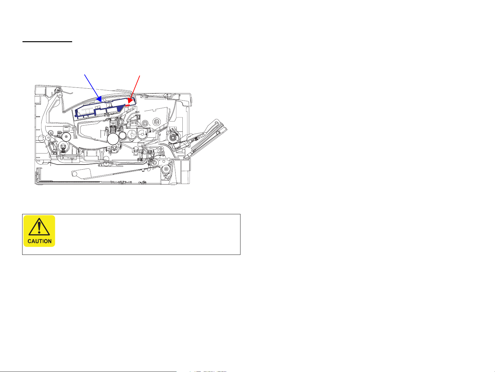
Laser Beam
Laser Opening Location
Handling Precautions
Disassembling and adjustment procedures not specified herein
may result in hazardous radiation exposure.
Do not disassemble or attempt to adjust the Laser Scanner unit
for any reason whatsoever. When the Laser Scanner unit
malfunctions, replace it with a new one.
Laser OpeningsLaser Scanner Unit
Page 7
Prohibited Matters
Never deactivate the safety equipment installed on the product for any reason
whatsoever.
Never modify the safety equipment or replace it with part not approved by
EPSON. Doing so may cause the safety functions to stop working properly, and
may result in fire or injury.
Never modify the product. If you are instructed to do so, however, fully
understand the instruction and perform the modification.
To prevent an electric shock, burn, injury, etc., always turn the
printer off and unplug the power cord before starting maintenance
work. When the power supply cable must be connected to measure
voltage or for any other task, strictly follow the instructions and use
extreme caution in working on electronic components.
Pay particular attention to the high-voltage part indicated with the
symbol on the left.
Do not touch the high temperature parts indicated with the symbol
on the left. Those parts are extremely hot immediately after use. If
you need to replace those parts, leave the printer until it cools.
Connect the printer to an electrical outlet that matches the printer’s
rated voltage and power requirements.
Do not connect any other devices to the electrical outlet supplying
the printer. Doing so can cause overloading of the electrical circuit
and may cause a fire.
Do not use extension cords or power adapters to plug multiple
devices into the same outlet. Power plug and electrical outlet should
be free from dust or foreign objects.
The printer should be properly grounded to prevent electric shock.
The grounding terminal should be one of the followings:
a. One of the electrical outlet
b. One that is grounded by a D-type grounding construction.
(The former third-type grounding construction; grounding
resistance under 100 Ω).
Power cord should not be deformed or damaged. If the cord is
damaged, replace it with a new one dedicated for the product.
Use the specified service parts for repair and maintenance.
When using compressed air products; such as air duster, for
cleaning during repair and maintenance, the use of such products
containing flammable gas is prohibited.
After replacing the Fuser Unit or any other parts to which AC
voltage is applied, be sure to check the part is properly installed and
the connecting cables are not caught between metal parts.
Otherwise a fire or an electric shock may occur.
Fuse on the Power Supply Unit must not be replaced under any
circumstances.
Page 8
Before performing repair and maintenance work, read and
understand the documents of the product (e.g. service manual).
Be sure to follow the specified steps and use the prescribed tools
described in the documents.
When disassembling or assembling the product, make sure to wear
gloves to avoid injury from metal parts with sharp edges.
Take care not to drop any screws, washers, or clips inside the
printer body. Should it fall in, do not boot up your printer until the
part has been safely removed.
After reassembling the printer, make sure all the parts and the
screws are put back in place and the cables are not caught between
metal parts.
Do not use vacuum cleaner for home use to clean up spills of
powdered toners. The very fine particles can cause fire/explosion.
Sweep them thoroughly with a broom or wipe them with a cloth
moistened with neutral detergent. If a large amount of toner is
spilled, use a toner vacuum designed specifically to clean toner.
Ozone gas is generated by the printer as a by-product of the
printing process. The amount of gas is too small to be harmful,
however, some users may feel uncomfortable under the following
conditions. It is desirable to advice the users to ventilate the room
when using the printer.
When using the printer for a long period of time in a room with
poor ventilation.
When printing a large amount of documents at a time.
When using multiple printers in the same room.
In order to protect sensitive microprocessors and circuitry, use
static discharge equipment, such as anti-static wrist straps, when
accessing internal components.
Though toner and developer are safe for human body, they may
cause irritation to skin and eyes. If toner gets into your eyes, wash it
away immediately with water. If irritation continues, see a physician.
If toner gets in your mouth, rinse immediately with plenty of water.
If swallowed, induce vomiting and consult a physician.
Do not throw used toner cartridges or toner into the flames.
Do not use thinner or alcohol when cleaning the product as it may
result in discoloration or deformation.
Page 9

Revision History
This manual is revised when the system, component, or part of the product is modified as a result of continuing improvements to the product’s performance and functions.
See the table below for recent updates.
Revision Date of Issue Description
A January 16, 2008 First Release
B February 1, 2008 All chapters:
Some connector numbers described in all chapters were corrected.
Chapter 3:
Service request errors were changed.
Chapter 4:
An adjustment point was added in the Developing Unit removal procedure.
“ Disassembly Flowchart” (p.76) was changed.
“ Disassembly Flowchart” (p.120) was changed.
PF Paper Conveyance Clutch figure was changed.
Chapter 5:
Firmware update was added in “5.1 Adjustment Item” (p.141).
“5.2.2 Updating firmware” (p.145) was added.
Chapter 7:
Some explanations in “7.3.1 Status Sheet” (p.166) were corrected.
Page 10

Contents
Chapter 1PRODUCT DESCRIPTION
1.1 Product Specifications. ......................................................................................... 4
1.1.1 Basic Specifications. .................................................................................. 4
1.1.2 Paper Specifications .................................................................................. 8
1.1.3 Replacement Parts . .................................................................................. 11
1.1.4 Controller Specifications. ........................................................................ 12
1.2 List of Printer Messages . .................................................................................... 13
Chapter 2OPERATING PRINCIPLES
2.1 Electrical parts layout. ........................................................................................ 16
2.2 Technical Explanation of Print Process. ............................................................. 20
2.2.1 Charging ................................................................................................... 20
2.2.2 Exposure ................................................................................................... 21
2.2.3 Development. ........................................................................................... 22
2.2.4 Transfer/Separation . ................................................................................ 23
2.2.5 Cleaning. .................................................................................................. 24
2.2.6 Fusing ....................................................................................................... 25
2.2.7 Paper exit section. .................................................................................... 26
2.2.8 Duplex/conveying section . ...................................................................... 27
2.3 Paper Feed ........................................................................................................... 28
2.3.1 Cassette paper feed section. ..................................................................... 28
2.3.2 MP tray paper feed section. ..................................................................... 29
2.3.3 Paper conveying section . ......................................................................... 30
2.3.4 Optional cassette paper feed section. ....................................................... 31
Chapter 3TROUBLESHOOTING
3.4 Troubleshooting................................................................................................... 37
3.4.1 Paper Jam Error........................................................................................ 37
3.4.2 LED Indication ......................................................................................... 40
3.4.3 Controller-related Service Call Errors. .................................................... 47
3.4.4 Image Quality Problems. ......................................................................... 57
3.4.5 Electrical Problems. ................................................................................. 61
3.4.6 Mechanical Problems . ............................................................................. 63
Chapter 4DISASSEMBLY AND ASSEMBLY
4.1 Preliminary Check............................................................................................... 66
4.1.1 Tool List ................................................................................................... 66
4.1.2 Parts/Units that Should Not be Disassembled. ........................................ 66
4.1.3 How to Read this Chapter . ..................................................................... 67
4.2 List of Disassembly/Reassembly Parts/Units. .................................................... 69
4.3 Main Unit Disassembly/Reassembly. ................................................................. 70
4.3.1 Group 1..................................................................................................... 70
4.3.2 Group 2..................................................................................................... 75
4.3.3 Group 3..................................................................................................... 82
4.3.4 Group 4..................................................................................................... 87
4.3.5 Group 5..................................................................................................... 92
4.3.6 Group 6..................................................................................................... 98
4.3.7 Group 7................................................................................................... 106
4.3.8 Group 8................................................................................................... 113
4.3.9 Group 9................................................................................................... 119
4.3.10 Group 10............................................................................................... 126
4.3.11 Group 11............................................................................................... 131
4.3.12 Group 12............................................................................................... 136
3.1 Troubleshooting Flowchart . ............................................................................... 33
3.2 Initial Checks. ..................................................................................................... 33
3.3 Symptoms............................................................................................................ 34
3.3.1 Errors indicated by the LEDs . ................................................................. 34
3.3.2 Print Quality Problems . ........................................................................... 34
3.3.3 Electrical Problems. ................................................................................. 36
3.3.4 Mechanical Problems . ............................................................................. 36
Chapter 5ADJUSTMENT
5.1 Adjustment Item................................................................................................ 141
5.2 Adjustment ........................................................................................................ 142
5.2.1 Writing USB ID. .................................................................................... 142
5.2.2 Updating firmware . ............................................................................... 145
Page 11

Chapter 6MAINTENANCE
6.1 Cleaning............................................................................................................. 151
Chapter 7APPENDIX
7.1 Connection Summary . ...................................................................................... 155
7.1.1 Connection Diagram. ............................................................................. 155
7.1.2 Board Connection Summary ................................................................. 156
7.2 Control Panel Special Operations. .................................................................... 162
7.2.1 Operation Method & Functions. ............................................................ 162
7.2.2 Special Menu . ........................................................................................ 165
7.3 Information Sheet . ............................................................................................ 166
7.3.1 Status Sheet . .......................................................................................... 166
7.3.2 Engine Status Sheet . .............................................................................. 168
7.3.3 Print Log Report . ................................................................................... 170
7.4 Exploded Diagram / Parts List . ........................................................................ 172
Page 12

PRODUCT DESCRIPTION
CHAPTER
1
Page 13
EPSON AcuLaser M2000D/M2000DN/M2010D/M2010DN Revision B
1.1 Product Specifications
AcuLaser M2000D/M2000DN/M2010D/M2010DN is a non-impact monochrome
page printer that takes advantage of a laser and electrophotographic technologies.
1.1.1 Basic Specifications
PRINTER SPECIFICATIONS
Item Spec.
Resolution 600 dpi, 1200 dpi
Print speed (Single-sided / Duplex) 28 ppm / 14 ppm
Warm-up time (23°C, 50% RH) Less than 17 seconds
Control Panel No LCD
CPU 64bit RISC CPU (300MHz)
RAM
Interfaces Standard model: Hi-Speed USB 2.0 (1.1
Printer Language ESC/Page (B/W), FX, ESCP2, I239X,
Dimensions (Main unit) 378 mm (W) x 390 mm (D) x 255 mm (H)
Weight (Main unit) Less than 11.5 kg
Power supply AC 110 V: 60 Hz
Standard Standard model: 32MB
Network model: 64MB
Max. Standard model: 288MB
Network model: 320MB
compatible) and Parallel Port
Network model: Hi-Speed USB 2.0 (1.1
compatible) and Ethernet Port
PCL5e, PCL6, Adobe PostScript3 and
PDF1.3
AC 220 ~ 440 V: 50 Hz / 60 Hz
Item Spec.
Power consumption
(100V/110V/220-240V)
Noise Printing 53 dB
Storage and transportation conditions Temperature: 0 ~ 35 °C
Life 100,000 pages or five years
Max. 110 V: 780 W
220 V ~ 240 V: 840 W
Printing 110 V: 449 W
220 V ~ 240 V: 465 W
Ready
(Eco Fuser ON)
Sleep 110 V: 3 W
Stand by 0 W
Standby 30 dB
110 V: 7 W
220 V ~ 240 V: 7 W
220 V ~ 240 V: 3 W
Humidity: 15 ~ 80% RH
OPTIONAL UNIT
Optional paper
cassette unit
Capacity: Up to 250 sheets
Paper size: A4, A5, B5, Letter, Executive, LGL 13” (GLG), F4”
PRODUCT DESCRIPTION Product Specifications 4
Page 14

EPSON AcuLaser M2000D/M2000DN/M2010D/M2010DN Revision B
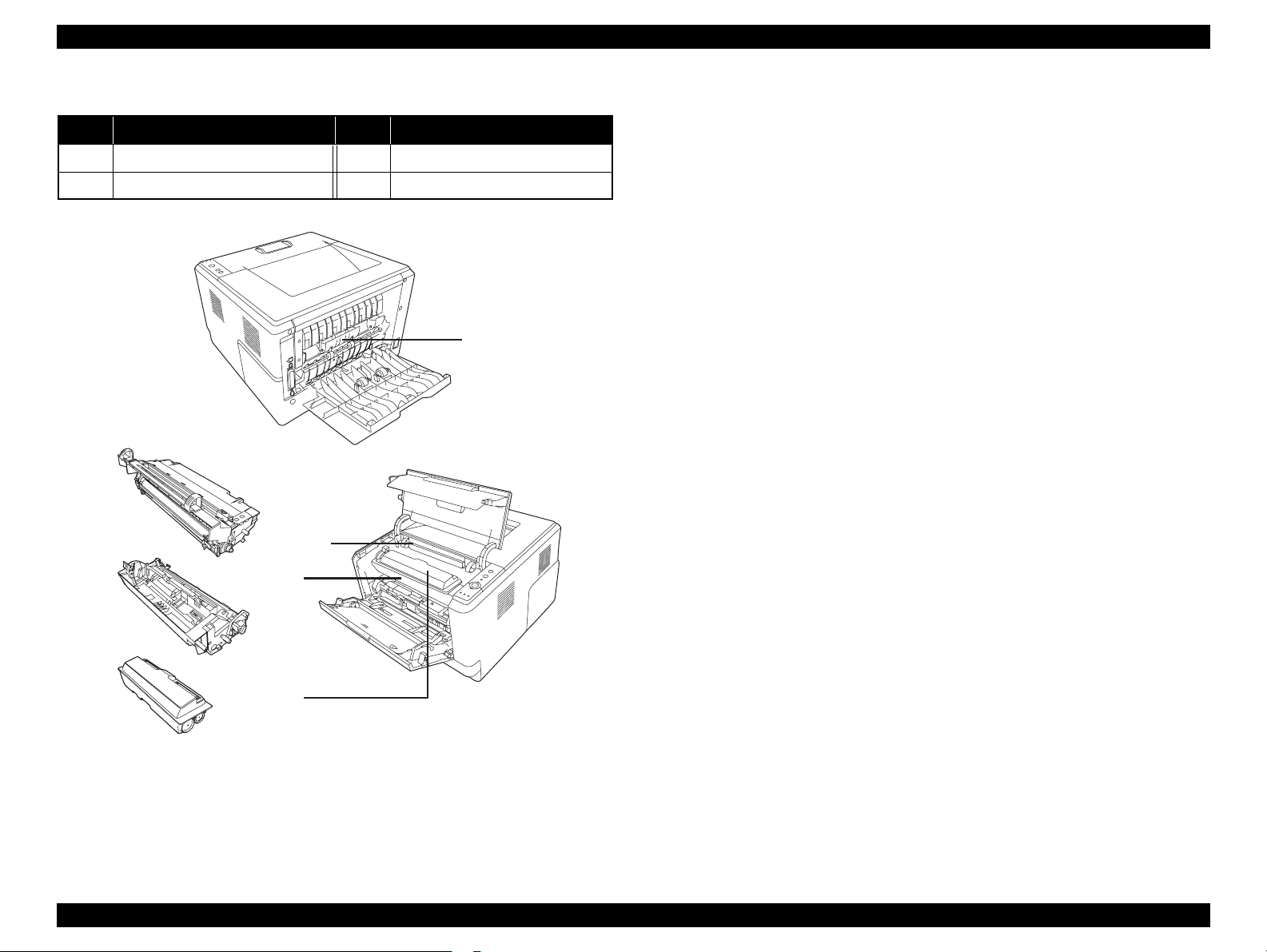
EXTERNAL VIEW AND PART NAMES
Table 1-1. Part Names
No. Name No. Name
1 Top cover (Cover A) 4 MP tray
2 Control Panel 5 Subtray
3 Standard lower paper cassette 6 Stopper
1
2
6
5
3
4
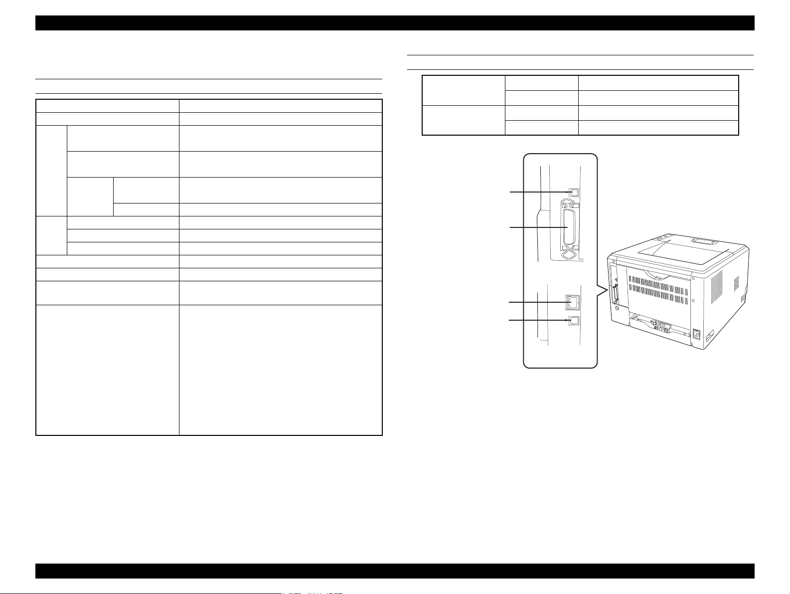
Table 1-2. Part Names
No. Name No. Name
1 Rear cover 5 USB interface connector
2 AC inlet 6 Network interface connector
3 Power switch 7 Parallel interface connector
4 Option cover
5
1
2
7
3
[Standard model]
6
5
Figure 1-1. Front view
[Network model]
4
Figure 1-2. Rear view
PRODUCT DESCRIPTION Product Specifications 5
Page 15
EPSON AcuLaser M2000D/M2000DN/M2010D/M2010DN Revision B
Table 1-3. Part Names
No. Name No. Name
1 Fuser unit 3 Developer unit
2 Photoconductor unit 4 Toner cartridge
1
2
3
2
3
4
4
Figure 1-3. Inside the printer
PRODUCT DESCRIPTION Product Specifications 6
Page 16
EPSON AcuLaser M2000D/M2000DN/M2010D/M2010DN Revision B
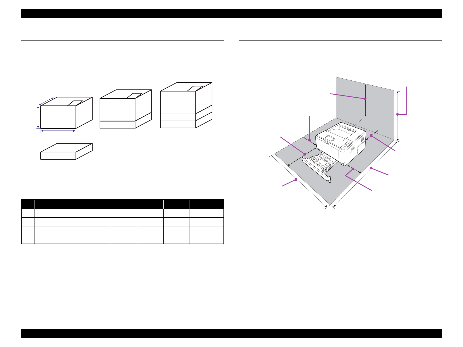
DIMENSIONS AND WEIGHT
The following figure shows the dimensions and weight of the printer.
NOTE 1 : Manufacturing tolerance is ±5 mm in dimensions and ±0.5 kg in weight.
2 : Imaging cartridges are not included in the weight of the main unit.
D
No. 2
H
NO. Configuration W*1 D H Weight
1 Main unit 379mm 390mm 255mm 11.5kg or less
2 Main unit + One Option Feeder 378mm 390mm 355mm 14.5kg
3 Main unit + Two Option Feeders 378mm 390mm 454mm 17.5kg
4 Option Feeder 375mm 390mm 100mm 3.0kg
No. 1
W
No. 4
Figure 1-4. Dimensions and Weight
Table 1-4. Dimensions and Weight List
No. 3
INSTALLATION SPACE REQUIREMENTS
The following figure shows the dimensions of the space required around the printer.
Be sure to provide the space for installation, operation, and maintenance.
455mm*
200mm
300mm
500mm
200mm
1,090mm
978mm
300mm
* 655 mm is required when two option feeders are installed.
Figure 1-5. Installation Space Requirements
PRODUCT DESCRIPTION Product Specifications 7
Page 17

EPSON AcuLaser M2000D/M2000DN/M2010D/M2010DN Revision B
1.1.2 Paper Specifications
SUPPORTED PAPERS
Table 1-5. Supported Papers
Paper Feeder Paper Type Paper Size
Capacity
(Height)
Weight
Standard Cassette Standard paper*/Plain paper/Recycled paper A4, A5, B5, LT, HLT, LGL,GLG, EXE, F4 250 sheets 60 ~ 90 g/m
Fine quality paper A4, A5, B5, LT, HLT, LGL, GLG, EXE, F4 28 mm 91 ~ 120 g/m
MP tray Standard paper*/Plain paper/Recycled paper A4, A5, B5, LT, HLT, LGL, GLT, GLG, EXE, F4 50 sheets 60 ~ 90 g/m
Fine quality paper A4, A5, B5, LT, HLT, LGL, GLT, GLG, EXE, F4 5 sheets 91 ~ 120 g/m
Special media Transparency A4, LT 5 sheets ---
Postcard Postcard 20 sheets 190 g/m
Label A4, LT 5 sheets ---
Thick paper A4, A5, B5, LT, EXE 5 sheets 121~ 220 g/m
Envelope C5, C6, DL, Com10, Monarch, ISO-B5 5 sheets ---
User defined Width: 70.00 mm ~ 215.90 mm
Length: 148.00mm ~ 356.00 mm*
1
50 sheets 60 ~ 90 g/m
5 sheets 91 ~ 220 g/m
Duplex unit Standard paper*/Plain paper/Recycled paper A4, LT --- 60 ~ 105 g/m
Option Cassette Standard paper*/Plain paper/Recycled paper A4, A5, B5, LT, LGL, GLG, EXE, F4 250 sheets 60 ~ 120 g/m
Fine quality paper A4, A5, B5, LT, LGL, GLG, EXE, F4 28 mm 91 ~ 120 g/m
* : Standard paper: Xerox Premier 80gsm
*1: When 297mm or longer length paper is used, the user needs to support the rear end of the paper with his/her hand.
2
2
2
2
2
2
2
2
2
2
2
PRODUCT DESCRIPTION Product Specifications 8
Page 18

EPSON AcuLaser M2000D/M2000DN/M2010D/M2010DN Revision B
UNSUITABLE PAPERS
The following types of paper should not be used, otherwise decreased print quality,
paper misfeeds, or damage to the printer may occur.
Specially-treated papers, such as carbon-backed, non-carbon, heat-sensitive,
pressure-sensitive, or acid paper
Extremely thick or extremely thin papers
Damp paper
Art paper, coated paper for color printers
Extremely smooth or extremely rough paper, or paper with uneven surface
Perforated paper or paper with punched hole
Folded, curled, wrinkled, or torn paper
Paper of a non-standard shape (not rectangular)
Label that peels off easily
Papers with glue, staples, or paper clips
Inkjet printer paper (Photo Quality Ink Jet Paper, Glossy Paper, Glossy Film, etc.)
Printouts printed by a heat-transfer printer or an inkjet printer
Transparency for other color laser printers or color photocopiers
Printouts printed by another color/monochrome laser printer or a photocopier
Sheets of paper stuck together using glue or the like
Postcards for inkjet printers
Iron-on Transfer Paper (for inkjet printers or laser printers)
Paper that deteriorates or discolors at 225 °C or lower
When using illustrated postcards, paper feed rollers may be soiled with paper dust
and these cards may not be fed properly. In this case, clean the rollers with
reference to Chapter 6 “MAINTENANCE” (p.150)
PRODUCT DESCRIPTION Product Specifications 9
Page 19

EPSON AcuLaser M2000D/M2000DN/M2010D/M2010DN Revision B
PRINTABLE AREA
Maximum print area (Printing is guaranteed)
Paper width: 215.9 mm x Length: 356.0 mm
Guaranteed print area
Area excluding 4-mm margins on all four edges
4.0 mm 4.0 mm
4.0 mm4.0 mm
ENVELOPE ORIENTATION
Envelope Size
Feeding
Direction
↑
DL, C6, Com10, Monarch C5, ISO-B5
POSTCARD ORIENTATION
Postcard type
Feeding
Direction
↑
Postcard Front side printing Postcard Reverse side printing
Load envelopes on the MP tray with the side to be printed face
up.
Proper paper feeding is not guaranteed for printing on the
backside of envelopes.
Do not use envelopes that have a tape or glue.
Table 1-6. Guaranteed Print Area
PAPER EJECT/CAPACITY
Paper eject Capacity Remarks
Face down 250* sheets 200* sheets for duplex printing.
* : When standard paper (A4) is used.
PRODUCT DESCRIPTION Product Specifications 10
Page 20

EPSON AcuLaser M2000D/M2000DN/M2010D/M2010DN Revision B
1.1.3 Replacement Parts
Consumables
Toner Cartridge : 8,000 pages / 3,500pages
Periodic replacement parts
This printer does not include any parts or units needing periodic replacement.
PRODUCT DESCRIPTION Product Specifications 11
Page 21
EPSON AcuLaser M2000D/M2000DN/M2010D/M2010DN Revision B
1.1.4 Controller Specifications
BASIC SPECIFICATIONS
CPU VR5500 (300MHz)
Enhanced Technology RIT (NICE)
RAM Standard (on-board) Standard model: 32MB
Network model: 64MB
Maximum Standard model: 288MB
Network model: 320MB
Expansion Type SDRAM 90pin DIMM
(64MB, 128MB, 256MB)
Numbers of slot 1 slot
ROM Type 16-bit width (3.3V)
Program 16MB
Font Included in the program
EEPROM Serial type 128Kbit
Control panel Three buttons and six LEDs. No LCD
Printer language ESC/Page (B/W), FX, ESC2, I239X, PCL5e, PCL6,
Adobe PostScript3 and PDF1.3
Auxiliary software
Status Sheet printing
EpsonNetConfig (Web) (Network model only)
USB Ext I/F Status Sheet
Network Status Sheet printing (Network model
only)
PS3 Status Sheet printing
PS3 Font List printing
PCL Font Sample printing
Hex dump
MAINTENANCE MODE (only for Engine Status
Sheet and Print Log Report)
EXTERNAL INTERFACES
Standard model USB
Parallel
Network model USB
Network 100BaseTX/10BaseT
USB
Parallel
Network
USB
Figure 1-6. External Interfaces
2.0 HS
IEEE1284 compliant
2.0 HS
[Standard model]
[Network model]
PRODUCT DESCRIPTION Product Specifications 12
Page 22
EPSON AcuLaser M2000D/M2000DN/M2010D/M2010DN Revision B
1.2 List of Printer Messages
The following table shows the printer’s LEDs indications in each printer status.
The meanings of the symbols used in the table are as follows.
O:Lights
---: Lights or flashes depending on the condition
X: Off
Δ1: Flashes on and off at intervals of 0.3 seconds
Δ2: Flashes on and off at intervals of 0.6 seconds
Δ3: Flashes on for 0.6 seconds and off for 2.4 seconds
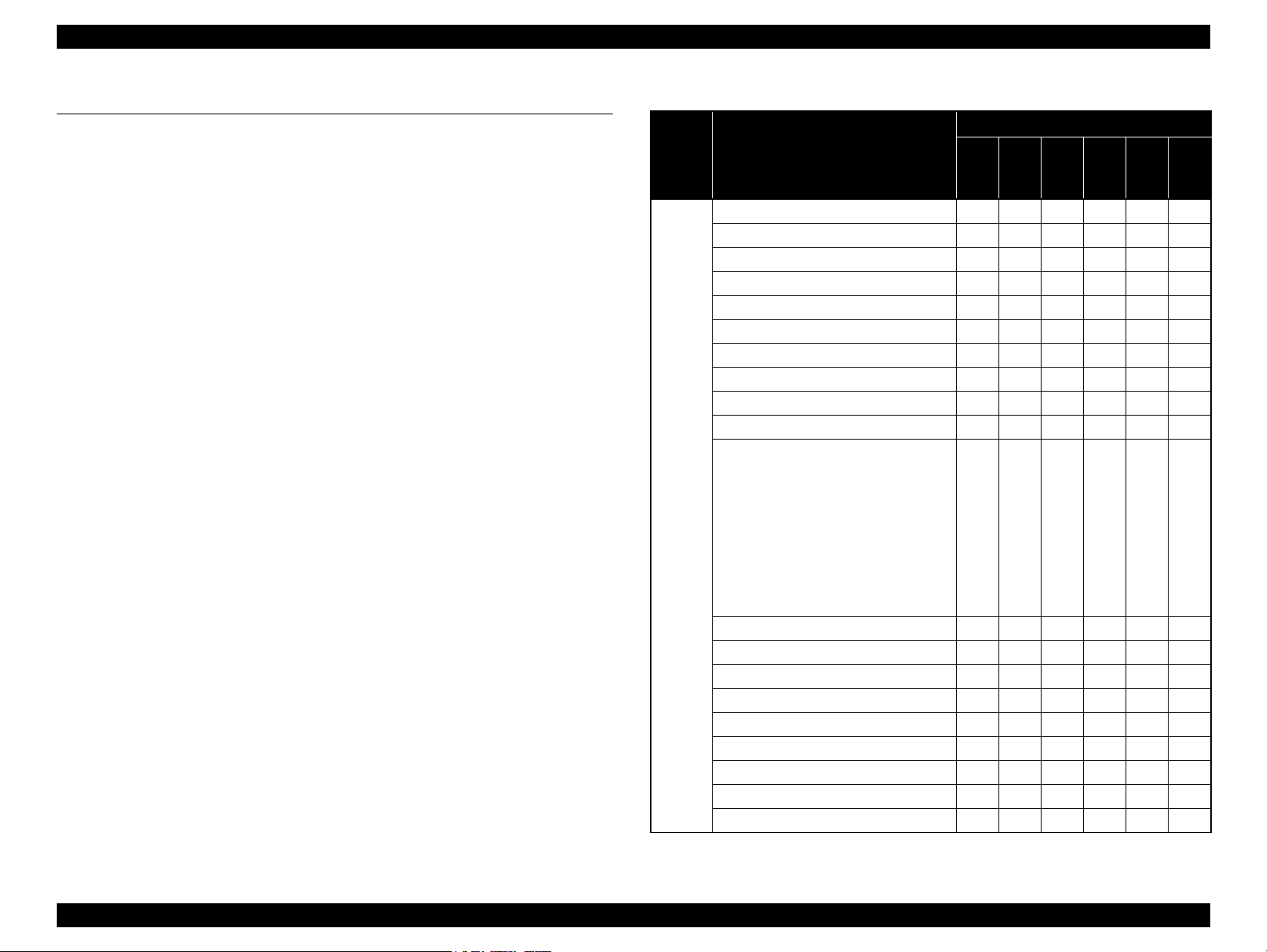
Table 1-7. List of Printer Messages
Sort Printer Status
ROM CHECK XXXOXX
RAM CHECK XXOXXX
Unable Clear Error X --- --- --- X ---
Self Test XOXXXX
Reset All Δ1
Reset --- --- --- --- --- --Cancel All Print Job Δ1 Δ1 --- X Δ1 ---
Cancel Print Job (by panel) Δ1 X --- X Δ1 ---
Writing ROM P --- --- --- --- X Δ1
Form Feed X --- --- --- --- Δ1
Status Sheet
ESC/Page Font Sample
PCL Font Sample
Status
ESCP2 Font Sample
FX Font Sample
1239X Font Sample
PS3 Status Sheet
PS3 Font List
Engine Status Sheet
Warming Up X --- --- --- Δ1 ---
Offline Δ3 --- --- --- X ---
Cancel Print Job (by host) Δ1 --- --- --- Δ1 ---
Filling toner xx*1 min --- Δ3 Δ3 Δ3 --- --Sleep: X --- --- --- Δ3 ---
Ready X --- --- --- O ---
(Printing) X --- --- --- --- ---
(Communication with inactive I/F) --- --- --- --- --- ---
(Job being executed (ready)) --- --- --- --- --- ---
LEDs status
Error
Memory
X X X Δ1 Δ1
X --- --- --- --- Δ1
Toner
Paper
Ready
Data
*1: "xx" indicates remaining time period (minutes).
PRODUCT DESCRIPTION List of Printer Messages 13
Page 23

EPSON AcuLaser M2000D/M2000DN/M2010D/M2010DN Revision B
Table 1-7. List of Printer Messages
LEDs status
Sort Printer Status
Error
Memory
Toner
Paper
Ready
Reserve Job Canceled X Δ1 --- --- --- ---
Form Data Canceled X Δ1 --- --- --- ---
Can't Print X Δ1 --- --- --- ---
Collate Disabled X Δ1 --- --- --- ---
Warning
Image Optimum X Δ1 --- --- --- ---
Check Paper Type X --- --- Δ1 --- ---
Need Memory X Δ1 --- --- --- ---
Toner Low X --- Δ1 --- --- ---
Worn Main unit Δ3 --- X --- --- ---
NonGenuineToner X --- Δ3 --- --- ---
*2: For details on the Service Req error code, see “3.4.3 Controller-related Service Call
Errors” (p.47).
*3: “WWWW” indicates the jammed or opened point. See “3.4.1 Paper Jam Error”
(p.37).
*4: “sss” indicates the Page Size setting of the control panel.
*5: “ttt” indicates the Paper Source setting (except for “Auto”) of the control panel.
*6: “sss” indicates the paper size setting in the Tray Menu of the control panel.
Table 1-7. List of Printer Messages
LEDs status
Sort Printer Status
Data
Service Req Cffff
*2
Error
Memory
Toner
Paper
OOOOOO
Service Req Eggg OXXXOO
Optional RAM Error OOXXX---
Write Error ROM P OOXXX---
Jam WWWW
*3
OXXOX---
Install Imaging Cart OXOXX---
Image Cart ID Error OXOXX---
NonGenuine Toner Δ1
XOXX---
Image Cart R/W Error OXOXX---
Replace Main Unit O Δ2
Δ2 Δ2 X ---
WWWW*3 Open OXXXX---
Error
Install LC1 O X X Δ1 X ---
Install LC2 OXXΔ1 X ---
Manual Feed sss
*4
Δ2 X X Δ2 Δ2 ---
Can't Print Duplex Δ1 X X O X ---
Paper Out ttt*5 sss
*6
O X X Δ1 X ---
Replace Toner O X O X X ---
Paper Set ttt*5 sss
*6
Δ1 X X Δ1 X ---
Print Overrun Δ1 O X X X ---
Mem Overflow Δ1 O X X X ---
Duplex Mem Overflow Δ1 O X X X ---
Invalid Data Δ1 O X X X ---
Invalid PS3 O O X X X ---
Data
Ready
PRODUCT DESCRIPTION List of Printer Messages 14
Page 24

OPERATING PRINCIPLES
CHAPTER
2
Page 25
AcuLaser M2000D/M2000DN/M2010D/M2010DN Revision B
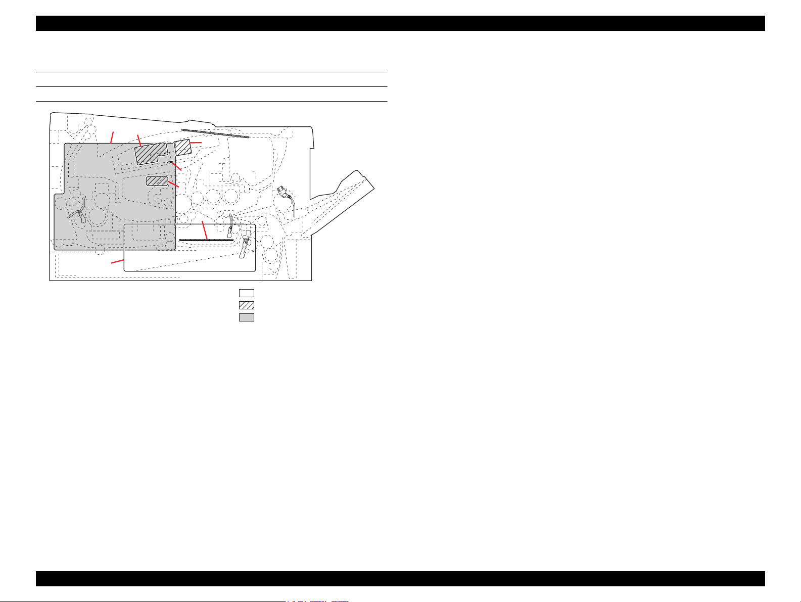
2.1 Electrical parts layout
POWER WRITING BOARDS
1
5
6
8
7
3
2
Figure 2-1. Power Writing Boards
1. Main Board Assy.
Main controller section:
Controls the software such as the print data processing and provides the
interface with computers.
Engine section:
4
Controls printer hardware such as high voltage/bias output control, paper
conveying system control, and fuser temperature control, etc.
2. LVPS
After full-wave rectification of AC power source input, switching for converting
to 24 V DC for output. Controls the fuser heater lamp.
3. HVPS
Generates main charging, developing bias, transfer bias.
4. Control Panel Board
Consists the LED indicators and key switches.
5. APC PWB
Generates and controls the laser beam.
Machine left
Machine inside
Machine right
6. PD PWB
Controls horizontal synchronizing timing of laser beam.
7. Zener PWB
Adjusts the drum surface potential.
8. Eraser lamp PWB
Eliminates the residual electrostatic charge on the drum.
OPERATING PRINCIPLES Electrical parts layout 16
Page 26
AcuLaser M2000D/M2000DN/M2010D/M2010DN Revision B
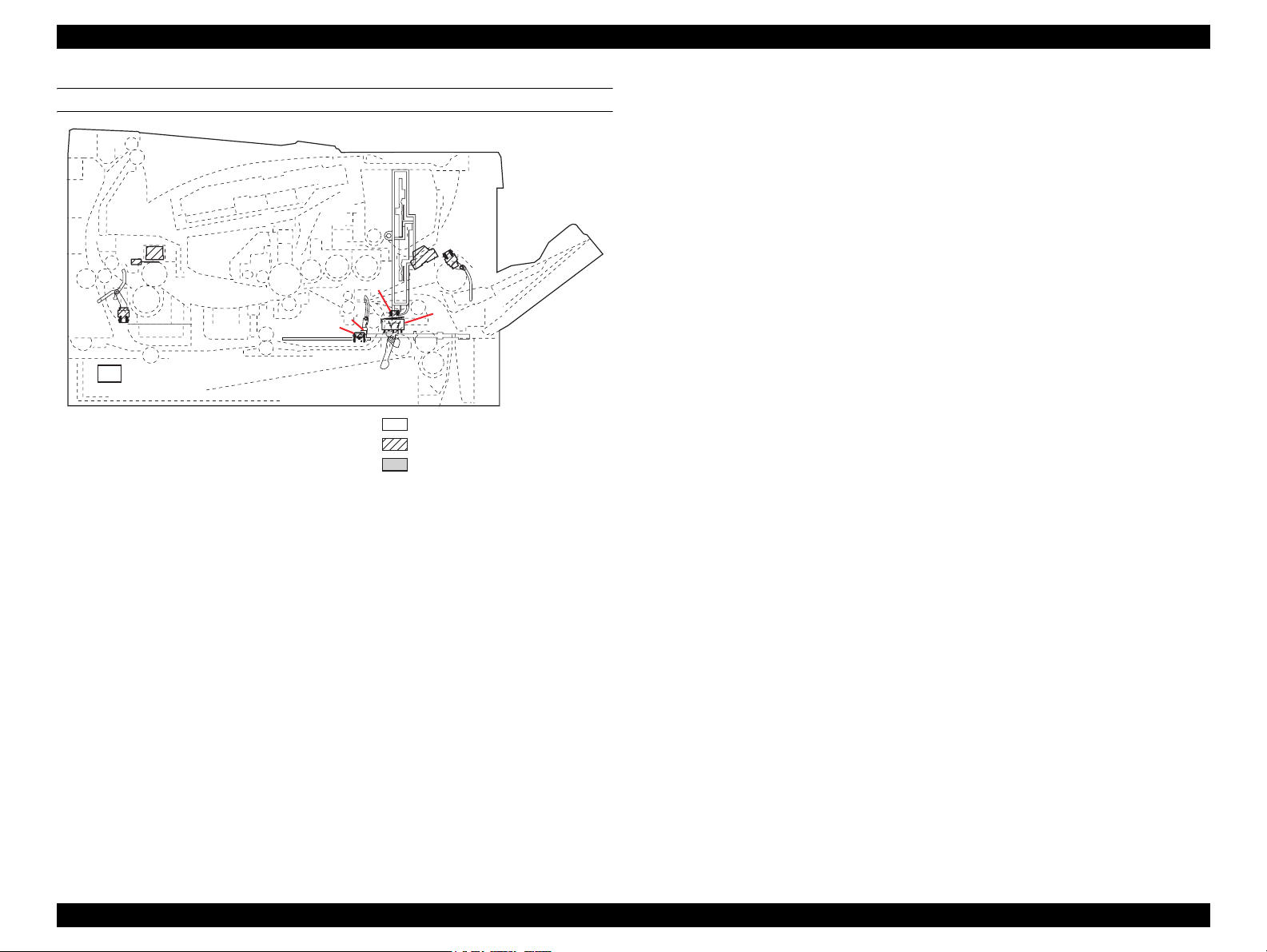
SWITCHES AND SENSORS
10
9
7
1
Figure 2-2. Switches and sensors
1. Power switch
Turns ON/OFF the AC power source.
2. Interlock switch
Shuts off 24 V DC power line when the top cover is opened.
3. Cassette switch
Detects open/close cassette.
6
5
4
3
8
2
4. Registration sensor
Detects the timing of primary paper feed.
5. Paper sensor
Detects the presence of paper in the cassette.
6. MP paper sensor
Detects the presence of paper on the MP tray.
7. Exit sensor
Detects paper jam in the fuser or duplex conveying section.
Machine left
Machine inside
Machine right
8. Toner sensor
Detects the quantity of toner in a toner container.
9. Fuser thermistor
Measures the heat roller temperature.
10. Fuser thermal cutout
Shuts off the power source to the fuser heater lamp when the heat roller reaches
extremely high temperature.
OPERATING PRINCIPLES Electrical parts layout 17
Page 27

AcuLaser M2000D/M2000DN/M2010D/M2010DN Revision B
OTHER ELECTRICAL COMPONENTS
8
2
4
10
1
Figure 2-3. Other electrical components
3
6
597
Machine left
Machine inside
Machine right
1. Main motor
Drives the paper feed/conveying section and fuser unit.
2. Polygon motor
Drives the polygon mirror.
3. Right cooling fan motor
Cools the interior of machine.
4. Left cooling fan motor
Cools the interior of machine.
5. Registration clutch
Controls the secondary paper feed.
6. Paper feed clutch
Controls the paper cassette paper feed.
7. Developing clutch
Controls the toner feed.
8. Duplex solenoid
Controls the paper conveying at the duplex conveying section.
9. MP paper feed solenoid
Controls the MPF bottom plate of the MP tray.
10. Fuser heater lamp
Heats the heat roller.
OPERATING PRINCIPLES Electrical parts layout 18
Page 28

AcuLaser M2000D/M2000DN/M2010D/M2010DN Revision B
OPTION PAPER FEEDER
5
Figure 2-4. Option Paper Feeder
1. PF Main Board
Controls electrical components in the paper feeder and serial communications with
1
4
3
the printer.
2. PF paper sensor
Detects the presence of paper in the cassette.
2
6
7
3. PF cassette switch
Detects the existence of the cassette.
4. PF paper feed sensor
Detects paper jam in the paper feeder.
5. PF paper feed motor
Machine left
Machine inside
Machine right
Drives the paper feed mechanism in the paper feeder.
6. PF paper feed clutch
Controls the drive of the paper feed roller.
7. PF paper conveying clutch
Controls the drive of the middle roller.
OPERATING PRINCIPLES Electrical parts layout 19
Page 29
AcuLaser M2000D/M2000DN/M2010D/M2010DN Revision B
2.2 Technical Explanation of Print Process
2.2.1 Charging
DRUM SECTION
The durable layer of organic photoconductor (OPC) is coated over the aluminum
cylinder base. The OPC tend to reduce its own electrical conductance when exposed to
light. After a cyclic process of charging, exposure, and development, the electrostatic
image is constituted over the OPC layer. Since the OPC is materialized by resin, it is
susceptible to damage caused by sharp edges such as a screwdriver, etc., resulting in a
print quality problem. Also, finger prints can cause deterioration of the OPC layer,
therefore, the drum (in the drum unit) must be handled with care. Substances like water,
alcohol, organic solvent, etc., should be strictly avoided. As with all other OPC drums,
the exposure to a strong light source for a prolonged period can cause a print quality
problem. The limit is approximately 500 lux for less than five minutes. If the drum
(drum unit) remains removed from the printer, it should be stored in a cool, dark place.
Drum cover A
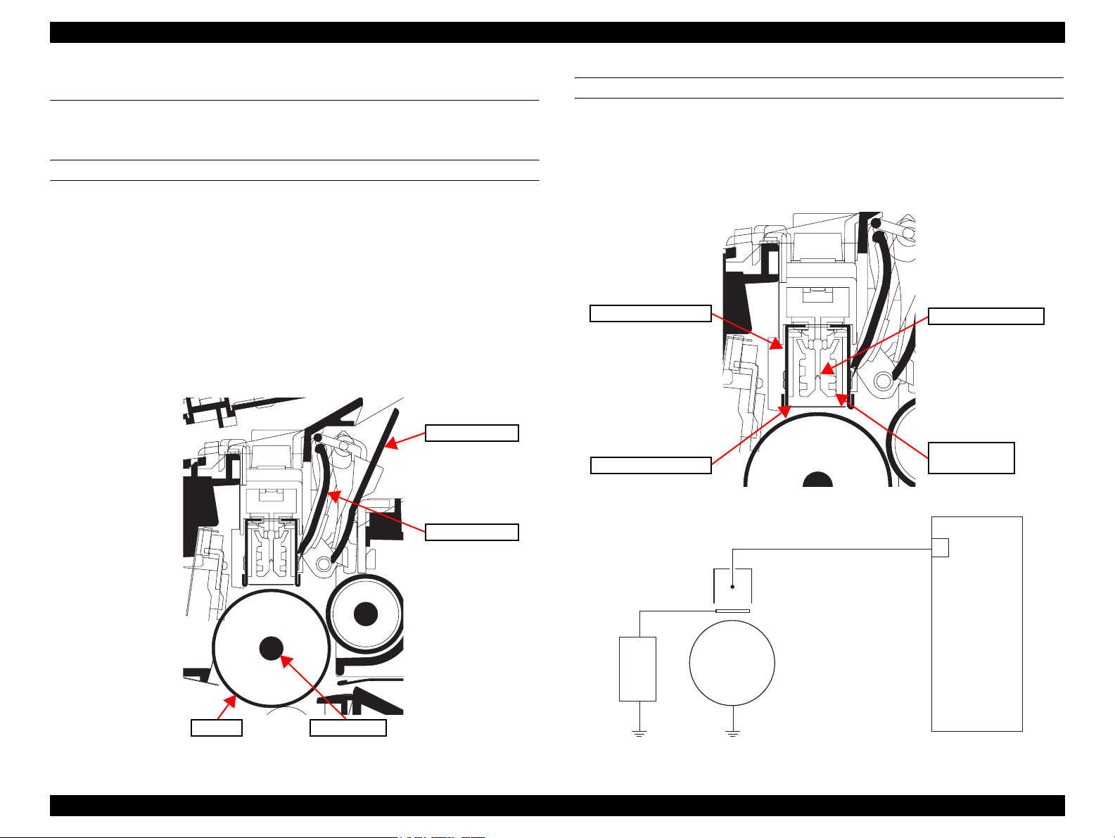
MAIN CHARGER UNIT
As the drum rotates in a “clean (neutral)” state, its photoconductive layer is given a
uniform, positive (+) corona charge dispersed by the main charger wire. Due to highvoltage scorotron charging, the charging wire can get contaminated by oxidization
after a long run. Therefore, the charger wire must be cleaned at a specific interval.
Cleaning the charging wire prevents print quality problems such as black streaks.
Main charger shield
Main charger wire
Main charger
Main charger grid
wire cleaner
Figure 2-6. Main charger unit
Drum cover B
Main charger wire
Zener
PWB
Main charger shield
Main charger grid
Drum
Main charger output
M
HVPS
Drum Drum shaft
Figure 2-5. Drum section
Figure 2-7. Drum unit and main charger unit block diagram
OPERATING PRINCIPLES Technical Explanation of Print Process 20
Page 30
AcuLaser M2000D/M2000DN/M2010D/M2010DN Revision B
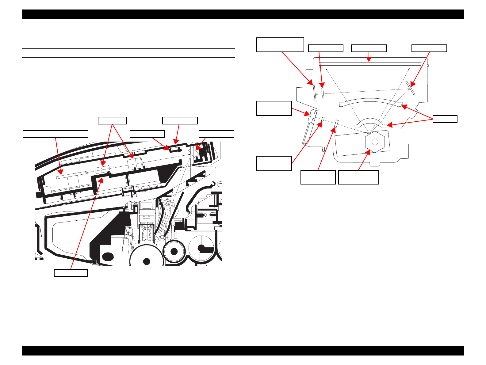
2.2.2 Exposure
LASER SCANNER UNIT (LSU)
The charged surface of the drum is then scanned by the laser beam from the laser
scanner unit.
The laser beam (780 nm wavelength) beam is dispersed as the polygon motor revolves
to reflect the laser beam over the drum. Various lenses and mirror are housed in the
laser scanner unit, adjust the diameter of the laser beam, and focalize it at the drum
surface.
Polygon motor (mirror)
F-θ lens
LSU shutter
LSU cover
LSU mirror
Pin photo diode
sensor (PD PWB)
Laser diode
(APC PWB)
Callimator
lens
LSU mirror
Cylindrical
lens
Figure 2-9. Laser scanner unit
Polygon motor
(mirror)
PD mirrorSOS lens
F-θ lens
LSU flame
Figure 2-8. Exposure section
OPERATING PRINCIPLES Technical Explanation of Print Process 21
Page 31

AcuLaser M2000D/M2000DN/M2010D/M2010DN Revision B
2.2.3 Development
The latent image constituted on the drum is developed into a visible image. The
developing roller contains a 3-pole (S-NS) magnet roller and an aluminum cylinder
rotating around the magnet roller. Toner attracts to the magnet sleeve since it is
powdery ink made of black resin bound to iron particles. Developing blade,
magnetized by magnet, is positioned approximately 0.3 mm above the magnet sleeve to
constitute a smooth layer of toner in accordance with the magnet sleeve revolution.
The developing roller is applied with the AC-weighted, positive DC power source.
Toner on the magnet sleeve is given a positive charge. The positively charged toner is
then attracted to the areas of the drum which was exposed to the laser light. (The gap
between the drum and the magnet sleeve is approximately 0.32 mm.) The non-exposed
areas of the drum repel the positively charged toner as these areas maintain the positive
charge.The developing roller is also AC-biased to ensure contrast in yielding by
compensating the toner’s attraction and repelling action during development.
Developing
blade
Developing
roller
Magnet roller
Magnet sleeve
Developing
clutch
Figure 2-11. Developing section block diagram
Developing bias output
B
HVPS
DLPDRN
Main Board Assy.
YC808-6
Blade
magnet
Magnet
sleeve
Magnet
roller
DLP
screw A
DLP
screw B
DLP case
Figure 2-10. Development section
OPERATING PRINCIPLES Technical Explanation of Print Process 22
Page 32

AcuLaser M2000D/M2000DN/M2010D/M2010DN Revision B
2.2.4 Transfer/Separation
The transfer/separation section consists of the transfer roller, discharger brush and
paper chute guide. A high voltage generated by the HVPS (High Voltage Power
Supply) is applied to the transfer roller for transfer charging. Paper after transfer is
separated from the drum.
DC brush holder
Discharger brush
Discharger
brush
Transfer roller
Paper chute guide
Transfer bushes
Figure 2-12. Transfer/separation section
Transfer
roller
Transfer bias
T
HVPS
GND
Figure 2-13. Transfer/separation section block diagram
OPERATING PRINCIPLES Technical Explanation of Print Process 23
Page 33

AcuLaser M2000D/M2000DN/M2010D/M2010DN Revision B
2.2.5 Cleaning
After the transferring process, the drum needs to be physically cleaned of toner which
is residual after the development process. The cleaning blade is constantly pressed
against the drum and scrapes the residual toner off to the sweep roller. The waste toner
is collected at the output end of the sweep roller and sent back to the toner container,
into the waste toner reservoir.
After the drum is physically cleaned, it then must be cleaned to the electrically neutral
state. This is necessary to erase any residual positive charge, ready to accept the
uniform charge for the next print process. The residual charge is canceled by exposing
the drum to the light emitted from the eraser lamp (PWB). This lowers the electrical
conductivity of the drum surface making the residual charge on the drum surface
escape to the ground.
Eraser lamp (PWB)
Main frame
Waste toner reservoir
ERASER
Eraser
lamp
(PWB)
Drum
Figure 2-15. Cleaning section block diagram
YC816-1
Main Board Assy.
Drum unit
Sweep roller Cleaning blade
Figure 2-14. Cleaning section
OPERATING PRINCIPLES Technical Explanation of Print Process 24
Page 34

AcuLaser M2000D/M2000DN/M2010D/M2010DN Revision B
2.2.6 Fusing
The toner on the paper is molten and pressed into the paper as it passes between the
heat roller and the press roller in the fuser unit. The heat roller has a heater lamp inside
which continuously turns on and off by the fuser thermistor to maintain the constant
temperature onto the heat roller surface. The heat roller is resin coated by florin to
prevent toner from accumulating on the roller after a long run. Care must be taken
while handling the heat roller not to scratch the roller surface as doing so may result in
print problems. Fuser temperature is optimized to the paper type. The heat roller has
four separators (claws) which are continuously in contact with its surface. These
separators (claws) prevent the paper on which toner has been fused from being wound
around the heat roller causing paper jam. The press roller is made of the heat-resistant
silicon rubber. This roller is used to strongly press the paper towards the heat roller by
means of press springs. The temperature of the heat roller is constantly monitored by
the main board assy. using the fuser thermistor. Should the temperature of the heat
roller exceed the predetermined value, the fuser thermal cutout is activated to
effectively disconnect the heater lamp from power.
Actuator
(exit sensor)
Separators
Press roller
Exit sensor
Upper fuser
frame
Fuser thermistor
Fuser thermal
Fuser lever L (R)Press spring holders
Figure 2-16. Fuser section
cutout
Fuser heater
lamp
Heat roller
Lower fuser
frame
Fuser
bushes
Press
springs
Fuser unit
HVPS
HEATN
SLEEP
ZCROSS
THERM
Main Board ASSY.
YC811-5
YC811-6
YC811-3
YC811-16
Fuser thermal cutout
Fuser
heater
lamp
Fuser
thermistor
L
N
YC102-1
YC102-3
LVPS
YC103-6
YC103-7
YC103-8
Figure 2-17. Fuser section block diagram
OPERATING PRINCIPLES Technical Explanation of Print Process 25
Page 35

AcuLaser M2000D/M2000DN/M2010D/M2010DN Revision B
2.2.7 Paper exit section
The paper exit section transports the paper which passed the fuser unit towards the top
tray. The paper which passed through the fuser unit turns on the actuator (exit sensor)
in the fuser unit, and is led by the guide comprised of the rear cover, frame and the FD
cover guide, finally reaching the upper FD roller. The paper is delivered to the top tray
by the rotation of the upper FD roller.
Exit pulley
Upper FD roller
Top tray
FD cover
Fuser exit pulley
Middle pulley
Rear cover
Actuator
(exit sensor)
Fuser unit
EXITN
Exit sensor
Figure 2-19. Paper exit section block diagram
Main Board ASSY.
YC807-3
Exit roller
Exit sensor
Figure 2-18. Paper exit section
OPERATING PRINCIPLES Technical Explanation of Print Process 26
Page 36

AcuLaser M2000D/M2000DN/M2010D/M2010DN Revision B
2.2.8 Duplex/conveying section
The duplex/conveying section consists of conveying path which sends the paper sent
from the eject section to the paper feed/conveying section when duplex printing.
Duplex solenoid
DUDR1
DUDR2
YC817-1
YC817-3
DU
roller
DU cover B DU holder
Lower base
cover
Middle
pulley B
Figure 2-20. Duplex/conveying section
Feed
roller
Feed
pulley
Fuser unit
Main Board ASSY.
EXITN
YC807-3
Exit sensor
Figure 2-21. Duplex/paper conveying section block diagram
OPERATING PRINCIPLES Technical Explanation of Print Process 27
Page 37

AcuLaser M2000D/M2000DN/M2010D/M2010DN Revision B
2.3 Paper Feed
Paper feed/conveying section consists of the paper feed unit that feeds paper from the
cassette and the MP tray paper feed unit that feeds paper from the MP tray, and the
paper conveying section that conveys the fed paper to the transfer/separation section.
2.3.1 Cassette paper feed section
Retard
guide
Retard
roller
Bottom plate
Feed
holder
Actuator Cassette base
(paper sensor)
Paper
sensor
Pickup
roller
Paper feed
roller
Retard
holder
Main Board ASSY.
Main motor
Paper feed
Clutch
MMOTRDYN
MOTCLK
REMOTEN
FEDDRN
PAP ER
YC805-3
YC805-4
YC805-5
YC808-4
YC806-3Paper sensor
Figure 2-23. Cassette paper feed section block diagram
Figure 2-22. Cassette paper feed section
OPERATING PRINCIPLES Paper Feed 28
Page 38

AcuLaser M2000D/M2000DN/M2010D/M2010DN Revision B
2.3.2 MP tray paper feed section
Paper feed
roller
MPF
separation
pad
MPF turn
guide
separator
MP paper
MPF
MPF
frame
MPF
sensor
friction pad
MPF bottom
plate
Figure 2-24. MP tray paper feed section
Actuator
(MP paper sensor)
MPF
base
MPF guide
R/L
middle traytray
Main Board ASSY.
MMOTRDYN
Main motor
MP paper
feed solenoid
MP paper sensor
MPF MPF upper
Figure 2-25. MP tray paper feed section block diagram
MOTCLK
REMOTEN
MPFDRN
HANDSN
YC805-3
YC805-4
YC805-5
YC809-2
YC804-3
OPERATING PRINCIPLES Paper Feed 29
Page 39

AcuLaser M2000D/M2000DN/M2010D/M2010DN Revision B
2.3.3 Paper conveying section
Lower
registration roller
Registration
sensor
Upper
registration roller
Figure 2-26. Paper conveying section
Actuator
(registration sensor)
Feed pulley
Main motor
HVPS
Registration
sensor
Main Board ASSY.
Registration
clutch
MMOTRDYN
MOTCLK
REMOTEN
REGDRN
REGN
YC805-3
YC805-4
YC805-5
YC808-2
YC811-11
Figure 2-27. Paper conveying section block diagram
OPERATING PRINCIPLES Paper Feed 30
Page 40

AcuLaser M2000D/M2000DN/M2010D/M2010DN Revision B
2.3.4 Optional cassette paper feed section
Actuator
(PF paper feed sensor)
Feed
bracket
Middle
roller
Retard
holder
Paper
pad
feed roller
Cassette
Retard
roller
PF Main
Board
Top
frame
PF paper
sensor
Bottom
plate
Actuator
(PF paper
sensor)
Cassette base
PF paper feed
Top
cover
PF cassette
switch
sensor
Feeder
pin
Pickup
roller
Bottom
holder
PF middle
pulley
Retard
guide
Cassette
cover
Printer
LVPS
Paper feeder 1
PF Main Board
Cassette
open/close
detection circuit
PF cassette
switch
PF paper
sensor
Paper
detection
circuit
Main Board ASSY.
+3.3 V
+24 V
PFSEL signal
processing
PFSEL
UART
Paper feeder
interface connector
CPU
Control
circuit
PF paper
feed sensor
PF paper
feed motor
PF paper
feed clutch
PF paper
conveying clutch
Figure 2-28. Optional cassette paper feed section
+3.3 V
+24 V
PFSEL
UART
Paper feeder 2
Paper feeder
interface connector
Figure 2-29. Paper feeder block diagram
OPERATING PRINCIPLES Paper Feed 31
Page 41

TROUBLESHOOTING
CHAPTER
3
Page 42

EPSON AcuLaser M2000D/M2000DN/M2010D/M2010DN Revision B
3.1 Troubleshooting Flowchart
Troubleshoot a problem of printer operation or print quality following the flowchart
shown below.
Start
Initial check
3.2 Initial Checks (page 33)
Recovered?
YES
NO
End of work
3.2 Initial Checks
The followings must be checked before starting troubleshooting.
Do the following ambient conditions satisfy the specification?
Surrounding space
Temperature and humidity
Does the paper type or paper condition satisfy the specification?
Are the consumables Epson-brand?
Is there significant contamination inside the printer?
Have the firmwares for the controller and engine controller been upgraded to the
latest version?
Find the cause of the problem
3.3 Symptoms (page 34)
Troubleshooting
3.4 Troubleshooting (page 37)
TROUBLESHOOTING Troubleshooting Flowchart 33
Page 43

EPSON AcuLaser M2000D/M2000DN/M2010D/M2010DN Revision B
3.3 Symptoms
3.3.1 Errors indicated by the LEDs
The status of the LEDs are indicated as shown below in the following table.
Lights
Flashes on and off at intervals of 0.3 seconds.
Flashes on and off at intervals of 0.6 seconds.
Flashes on for 0.6 seconds and off for 2.4 seconds.
Off
LED Indication Description Reference
A paper jam error is occurring.
Page 37
An error other than paper jam is occurring.
3.3.2 Print Quality Problems
Symptom Reference
Bands or smudges that appear at regular
intervals.
Bands or smudges appear on the printout at
regular intervals.
Page 57
Completely blank
Completely blank pages are printed.
Page 57
Completely black
Page 40
Completely solid black pages are printed.
Page 58
TROUBLESHOOTING Symptoms 34
Page 44

EPSON AcuLaser M2000D/M2000DN/M2010D/M2010DN Revision B
Symptom Reference
Areas of images are missing
Areas of the printed image are missing.
Black dots
Black dots appear on the printout.
ABC
123
ABC
123
Page 58
Page 59
Symptom Reference
Vertical line
A vertical black line appears on the printout.
Light or faint image
The printed image is light or faint.
ABC
123
Page 59
Page 59
Horizontal line
A horizontal black line appears on the printout.
ABC
123
TROUBLESHOOTING Symptoms 35
Page 59
Dirt on the background
The background is dark or dirty, or toner
smudges appear partially on the printout.
ABC
123
Page 60
Page 45

EPSON AcuLaser M2000D/M2000DN/M2010D/M2010DN Revision B
Symptom Reference
Toner smudges
Toner smudges appear on the top edge or nonprinted side of the page.
Wavy image
The printed image on the upper right side
(scanning start position) of the page is wavy.
ABC
123
Page 60
Page 60
3.3.3 Electrical Problems
Symptom Reference
The machine does not operate when the power switch is turned on.
Right cooling fan motor does not operate.
Left cooling fan motor does not operate.
Power supply fan motor does not operate.
Registration clutch does not operate.
Paper feed clutch does not operate.
Developing clutch does not operate.
MP paper feed solenoid does not operate.
Duplex solenoid does not operate.
Eraser lamp does not turn on.
The machine does not detect paper loaded in the cassette.
A paper jam in the paper feed/conveying section or fuser section is indicated
when the power switch is turned on.
The machine does not detect that the top cover is closed.
3.3.4 Mechanical Problems
Symptom Reference
No primary paper feed.
No secondary paper feed.
Skewed paper feed.
Multiple sheets of paper are fed at one time.
Paper jams.
Toner drops on the paper conveying path.
Abnormal noise is heard.
Paper becomes wrinkled, creased, or curled.
Page 61
Page 63
TROUBLESHOOTING Symptoms 36
Page 46

EPSON AcuLaser M2000D/M2000DN/M2010D/M2010DN Revision B
3.4 Troubleshooting
3.4.1 Paper Jam Error
When a paper jam error occurs, check the message displayed on the EPSON Status
Monitor, or the jam code printed on the Engine Status Sheet in order to find out the
jammed point, and check the relevant sensors, rollers, or any other relevant parts for
any abnormality.
FINDING JAMMED POINT
When a paper jam error message appears
EPSON Status Monitor Message Jammed Point
Remove cassette 3 and then remove any jammed paper.
Remove cassette 2 and then remove any jammed paper.
Remove cassette 1 and then remove any jammed paper.
Temporarily remove the paper from the MP tray.
Open cover B and remove any jammed paper.
Open the DM tray from either the front or the rear, whichever is accessible
from the space from which cassette 1 was removed, and then remove any
jammed paper.
Open cover A and remove the developer unit and photoconductor unit, and
then carefully remove any jammed paper.
c
d
e
f
ij
h
g
TROUBLESHOOTING Troubleshooting 37
Page 47

EPSON AcuLaser M2000D/M2000DN/M2010D/M2010DN Revision B
When a paper jam error message does not appear
Print the Engine Status Sheet and check the jam code on the printout to find out the
jammed point and the cause. The jam code is expressed in 8-digit hexadecimal.
00 NN NN NN
Fixed to 00 (1) (2) (3)
(1) Jammed point information*
Jam code Explanation
80 Reserved
40 Cassette 3 (option)
20 Cassette 2 (option)
10 Cassette 1
08 MP tray
04 Cover B
02 DM tray
01 Photoconductor unit (inside the printer)
(2) Jam cause information
Jam code Explanation Jammed point
10
11
12
20
21
22
30
Paper did not reach the registration sensor.
Paper did not go forward from the registration sensor.
The registration sensor detected paper at power-on.
Paper did not reach the fuser sensor.
Paper did not go forward from the fuser sensor.
The fuser sensor detected paper at power-on.
Paper did not reach the PF sensor of the optional
cassette 1.
efh
g
g
g
i
i
d
Jam code Explanation Jammed point
31
32
40
41
42
A1
A3
E0
F0 to FF Other paper jam errors
Paper did not go forward from the PF sensor of the
optional cassette 1.
The PF sensor of the optional cassette 1 detected
paper at power-on.
Paper did not reach the PF sensor of the optional
cassette 2.
Paper did not go forward from the PF sensor of the
optional cassette 2.
The PF sensor of the optional cassette 2 detected
paper at power-on.
Paper did not reach the exit sensor.
Paper did not go forward from the exit sensor.
An error occurs during printing and the printer engine
was stopped in the middle of an operation.
d
d
c
c
c
j
h
---
---
(3) Feeder
Jam code Explanation
00 MP tray
01 Cassette 1
02 Cassette 2 (option)
03 Cassette 3 (option)
07 Duplex printing
TROUBLESHOOTING Troubleshooting 38
Page 48

EPSON AcuLaser M2000D/M2000DN/M2010D/M2010DN Revision B
* : When no applicable code is found in the above table, the paper jam is occurring at
multiple points. In such case, convert the hexadecimal jam code into binary, and check
the binary code to find out the multiple points with reference to the table below.
Binary jam code Jammed point
10000000
01000000
00100000
00010000
00001000
00000100
00000010
00000001
Reserved
Cassette 3 (option)
Cassette 2 (option)
Cassette 1
MP tray
Cover B
DM tray
Photoconductor unit (inside the printer)
Example for reading the binary code:
05
00000101
00000100
Hexadecimal jam code
Binary jam code
00000001
JAMMED POINT
The diagram below shows the jammed points.
(
Fuser/Paper ejection section
(
Duplex/Conveying section
Optional Cassette 1
Optional Cassette 2
(
(
)
)
)
)
(
Cassette 1
MP tray
)
A: Registration sensor
B: Paper sensor
C: MP paper sensor
D: Exit sensor
E: PF sensor
F: PF sensor
Cover B
Photoconductor unit
(inside the printer)
TROUBLESHOOTING Troubleshooting 39
Page 49

EPSON AcuLaser M2000D/M2000DN/M2010D/M2010DN Revision B
3.4.2 LED Indication
The status of the LEDs are indicated as shown below in the following table.
Lights
Flashes on and off at intervals of 0.3 seconds.
Flashes on and off at intervals of 0.6 seconds.
Flashes on for 0.6 seconds and off for 2.4 seconds.
Off
LED
indication
EPSON Status Monitor Message Explanation Possible cause / Error-causing Part Check point / Remedy
Unable to write to ROM module Writing to the program ROM could not be
performed.
Developer unit or toner cartridge installed
incorrectly
Incompatible toner cartridge The installed toner cartridge is the one for
The printer failed to detect the toner
cartridge.
another destination.
Main Board Assy. Reboot the printer to make the printer
perform the writing operation again.
Replace the Main Board Assy. (See
P. 92)
Toner cartridge Install the toner cartridge correctly.
Replace the toner cartridge. (See P. 70)
Toner cartridge Replace the toner cartridge with the correct
one. (See P. 70)
TROUBLESHOOTING Troubleshooting 40
Page 50

EPSON AcuLaser M2000D/M2000DN/M2010D/M2010DN Revision B
LED
indication
EPSON Status Monitor Message Explanation Possible cause / Error-causing Part Check point / Remedy
Non-genuine toner cartridge installed The installed toner cartridge is not Epson-
brand.
Trouble with toner cartridge The printer detected that the toner cartridge
was faulty.
Cover A open The cover A is open. Cover A Close the cover A.
The printer does not detect that the cover A
is closed.
Cassette not installed The paper cassette is not installed. Paper cassette Install the cassette to the printer.
The printer does not detect that the cassette
is installed.
Printer set to Manual Feed “Manual Feed” is selected on the printer
driver.
Toner cartridge Replace the toner cartridge with an Epson-
brand cartridge. (See P. 70)
Toner cartridge Replace the toner cartridge. (See P. 70)
The actuator that presses the interlock
switch on the cover A is damaged.
Poor assembling or damage of the link
mechanism that presses the interlock
switch.
The interlock switch is faulty. Replace the interlock switch (LVPS). (See
Poor assembling or damage of the link
mechanism that presses the paper cassette
detection sensor.
The paper cassette detection sensor is
faulty.
Replace the cover A (top cover). (See
P. 113)
Check if the link mechanism is assembled
correctly. If not, reassemble it. If the
mechanism is damaged, replace it.
P. 75)
Check if the link mechanism is assembled
correctly. If not, reassemble it. If the
mechanism is damaged, replace it.
Replace the paper cassette detection sensor
(HVPS). (See P. 75)
Load paper into the MP tray and press the
Start/Stop button.
---
TROUBLESHOOTING Troubleshooting 41
Page 51

EPSON AcuLaser M2000D/M2000DN/M2010D/M2010DN Revision B
LED
indication
EPSON Status Monitor Message Explanation Possible cause / Error-causing Part Check point / Remedy
Unable to perform duplex printing The paper size or type is not supported for
Load paper supported for duplex printing.
duplex printing.
---
Paper out No paper is loaded on the paper feeder.
The printer does not detect paper loaded on
the feeder.
Poor assembling or damage of the actuator
for detecting paper.
---
Load paper on the feeder.
Check if the actuator is assembled correctly.
If not, reassemble it. If the actuator is
damaged, replace it.
Check if the paper sensor is connected to
the Main Board Assy. correctly.
Replace the paper sensor. (See P. 87)
Toner cartridge at end of service life The toner cartridge has reached the end of
Poor connection or damage of the paper
sensor.
Toner cartridge Replace the toner cartridge. (See P. 70)
its life.
Incorrect paper size The paper size selected in the printer
Load the correct sized paper on the feeder.
driver does not match with that of the
loaded paper.
---
Page contains too much data to process The spool file is deleted in the middle of
printing and another print job is started, or
the data is abnormal due to a
communication error.
Insufficient printer memory Processing operation is interrupted due to
insufficient memory or invalid operation to
the memory.
---
---
Delete the spool file using the printer driver,
and then press the Job Cancel button on the
printer.
Lower the print quality setting in the
printer driver.
Reduce the resolution of the image to be
printed.
Add more memory to the printer.
TROUBLESHOOTING Troubleshooting 42
Page 52

EPSON AcuLaser M2000D/M2000DN/M2010D/M2010DN Revision B
LED
indication
EPSON Status Monitor Message Explanation Possible cause / Error-causing Part Check point / Remedy
Not enough printer memory to print using
duplex function
The back of the page cannot be printed
because the memory is insufficient to
process the data for duplex printing. In this
case, only front side is printed.
---
Turn the frontside-printed paper over
and reload it on the printer, and then
press the Start/Stop button to print on the
back of the paper.
Lower the print quality setting in the
printer driver.
Reduce the resolution of the image to be
printed.
Add more memory to the printer.
Unable to process print data There is something wrong with the print
data.
PostScript module incompatible The installed PS3ROM module cannot be
---
The Main Board Assy. is faulty. Replace the Main Board Assy. (See P. 92)
Delete the spool file using the printer driver,
and then press the Job Cancel button on the
printer.
used by the printer.
General error E001
(Main Board EEPROM error)
The EEPROM (U800) on the Main Board
Assy. is inaccessible.
Mounting failure of the EEPROM (U800) Check if the EEPROM (U800) is properly
mounted. If not, fix it.
The Main Board Assy. is faulty. Replace the Main Board Assy. (See P. 92)
EEPROM (U800) is faulty. Replace the EEPROM (U800).
TROUBLESHOOTING Troubleshooting 43
Page 53

EPSON AcuLaser M2000D/M2000DN/M2010D/M2010DN Revision B
LED
indication
EPSON Status Monitor Message Explanation Possible cause / Error-causing Part Check point / Remedy
General error E002
(Main motor error)
The main motor ready signal could not be
detected within 2 seconds after the motor
becomes ON.
Poor connection between the main motor
(CN1) and the Main Board Assy. (YC805).
Reconnect the connector properly.
Check the connector cable for electric
continuity. If no continuity is found,
replace the cable.
There is some problem in the main motor
drive transmission path.
Check if the rollers and gears are
smoothly rotating. If not, apply grease to
the bearings and gears.
Check if any of the gears are damaged.
If so, replace the damaged gears.
The main motor is faulty. Replace the main motor. (See P. 92)
The Main Board Assy. is faulty. Replace the Main Board Assy. (See P. 92)
General error E004
(Polygon motor error)
The polygon motor ready signal could not
be detected within 6 seconds after the motor
becomes ON.
Poor connection between the polygon
motor (laser scanner unit) and the Main
Board Assy. (YC819).
Reconnect the connector properly.
Check the connector cable for electric
continuity. If no continuity is found,
replace the cable.
The laser scanner unit is faulty. Replace the laser scanner unit. (See P. 119)
The Main Board Assy. is faulty. Replace the Main Board Assy. (See P. 92)
General error E005
(Horizontal synchronization signal error)
The controller could not detect the
horizontal synchronization signal within the
The laser scanner unit is faulty. Replace the laser scanner unit. (See P. 119)
specified time period.
General error E008
(Fuser heater cable disconnection)
The fuser heater lamp was turned ON, but
the fuser temperature did not rise.
Poor connection of the fuser thermistor. Check if the connector (YC105) on the
LVPS is properly inserted. If not, reconnect
it.
Poor connection of the fuser heater lamp
connector.
Check if the connector (YC102) on the
LVPS is properly inserted. If not, reconnect
it.
Mounting failure of the fuser thermistor. Replace the fuser unit. (See P. 106)
Fuser thermal cut-out has been activated.
Mounting failure of the fuser heater lamp.
The fuser heater lamp has breaks.
TROUBLESHOOTING Troubleshooting 44
Page 54

EPSON AcuLaser M2000D/M2000DN/M2010D/M2010DN Revision B
LED
indication
EPSON Status Monitor Message Explanation Possible cause / Error-causing Part Check point / Remedy
General error E009
(Abnormally high fuser heater temperature)
General error E010
(Fuser thermistor short-circuit)
The fuser thermistor detected abnormal
high temperature.
The A/D value input from the fuser
thermistor is “0” (zero).
The fuser thermistor shorted out. Replace the fuser unit. (See P. 106)
The Main Board Assy. is faulty. Replace the Main Board Assy. (See P. 92)
Poor connection of the fuser thermistor. Check if the connector (YC105) on the
LVPS is properly inserted. If not, reconnect
it.
The fuser thermistor has breaks. Replace the fuser unit. (See P. 106)
Mounting failure of the fuser thermistor.
Fuser thermal cut-out has been activated.
Mounting failure of the fuser heater lamp.
The fuser heater lamp has breaks.
General error E011
(Zero cross signal error)
The Main Board Assy. did not receive the
zero cross signal during a specified time
period.
Poor connection between the HVPS
(YC202) and the Main Board Assy.
(YC811).
Reconnect the connector properly.
Check the connector cable for electric
continuity. If no continuity is found,
replace the cable.
Poor connection between the LVPS
Reconnect the connector properly.
(YC103) and the HVPS (YC201).
The LVPS is faulty. Replace the LVPS. (See P. 75)
The Main Board Assy. is faulty. Replace the Main Board Assy. (See P. 92)
General error E016
(Option cassette unit communication error)
The communication between the Main
Board Assy. and the PF main board of the
option cassette unit cannot be established.
Mounting failure of the option cassette unit. Check if the unit is properly mounted. If
not, fix it.
Poor connection between the Main Board
Assy. (YC818) and the PF interface
connector.
Reconnect the connector properly.
Check the connector cable for electric
continuity. If no continuity is found,
replace the cable.
The Main Board Assy. is faulty. Replace the Main Board Assy. (See P. 92)
Poor connection between the PF main board
(YC5) and the PF interface connector.
Reconnect the connector properly.
Check the connector cable for electric
continuity. If no continuity is found,
replace the cable.
The PF main board is faulty. Replace the PF main board. (See P. 136)
TROUBLESHOOTING Troubleshooting 45
Page 55

EPSON AcuLaser M2000D/M2000DN/M2010D/M2010DN Revision B
LED
indication
EPSON Status Monitor Message Explanation Possible cause / Error-causing Part Check point / Remedy
General error E998
(Engine communication error)
Communication error between the
controller on the Main Board Assy. and the
engine controller.
The firmware of the engine controller is
faulty.
The Main Board Assy. is faulty. Replace the Main Board Assy. (See P. 92)
Reinstall the engine controller firmware.
(See P. 148)
TROUBLESHOOTING Troubleshooting 46
Page 56

EPSON AcuLaser M2000D/M2000DN/M2010D/M2010DN Revision B
3.4.3 Controller-related Service Call Errors
Remedy
When a controller-related error occurs, first check on the initial check items listed
below. If the printer still does not recover, troubleshoot the problem with reference
to the tables given on the following pages. Find the error you face in the tables,
and replace the error-causing parts one by one.
Initial check
Is the printer properly grounded?
Are the connectors properly connected to the controller board?
Is the DIMM properly installed on the controller board?
Does the printer recover by turning the power off and back on several times?
Is there any equipment that causes noise around the printer?
When turning the printer off and on for the above initial check,
wait for several seconds before turning it back on. Do not turn it
back on immediately after power-off.
TROUBLESHOOTING Troubleshooting 47
Page 57

EPSON AcuLaser M2000D/M2000DN/M2010D/M2010DN Revision B
Error-causing parts
The status of the LEDs are indicated as shown below in the following table.
Light
Off
LED
indication
Classification Error code Explanation
C/D 0017 Occurrence of an interrupt exception
C/D 0081 TLB change exception
C/D 0082 TLB exception (load or fetch)
C/D 0083 TLB exception (store)
Error-causing parts (or factor)
Main Board Assy.
Causative Not causative Causative
Causative Not causative Causative
Causative Not causative Causative
Option
RAM DIMM
Noise or other
factor
Causative Not causative Causative
TROUBLESHOOTING Troubleshooting 48
Page 58

EPSON AcuLaser M2000D/M2000DN/M2010D/M2010DN Revision B
LED
indication
Classification Error code Explanation
C/D 0084 Address error exception (load or fetch)
C/D 0085 Address error exception (store)
C/D 0086 Bus error exception (store)
C/D 0087 Bus error exception (loading or storing data)
Error-causing parts (or factor)
Main Board Assy.
Causative Not causative Causative
Causative Not causative Causative
Causative Not causative Causative
Option
RAM DIMM
Noise or other
factor
Causative Not causative Causative
C/D 0088 System call exception
Causative Not causative Causative
C/D 0089 Breakpoint exception
Causative Not causative Causative
TROUBLESHOOTING Troubleshooting 49
Page 59

EPSON AcuLaser M2000D/M2000DN/M2010D/M2010DN Revision B
LED
indication
Classification Error code Explanation
C/D 0090 Reserve instruction exception
C/D 0091 Coprocessor disabled exception
C/D 0092 FPU exception (invalid operation)
C/D 0093 TLB exception
Error-causing parts (or factor)
Main Board Assy.
Causative Not causative Causative
Causative Not causative Causative
Causative Not causative Causative
Option
RAM DIMM
Noise or other
factor
Causative Not causative Causative
C/D 0094 XTLB exception
Causative Not causative Causative
C/D 0095 Cash exception
Causative Not causative Causative
TROUBLESHOOTING Troubleshooting 50
Page 60

EPSON AcuLaser M2000D/M2000DN/M2010D/M2010DN Revision B
LED
indication
Classification Error code Explanation
C/D 0096 Trap exception
C/D 0097 Floating point exception
C/D 0098 Watch exception
C/D 0128-254 Undefined trap
Error-causing parts (or factor)
Main Board Assy.
Causative Not causative Causative
Causative Not causative Causative
Causative Not causative Causative
Option
RAM DIMM
Noise or other
factor
Causative Not causative Causative
C/D 0255 NMI exception
Causative Not causative Causative
C/D 0256 Divide-by-zero
Causative Not causative Causative
TROUBLESHOOTING Troubleshooting 51
Page 61

EPSON AcuLaser M2000D/M2000DN/M2010D/M2010DN Revision B
LED
indication
Classification Error code Explanation
C/D 0257 Operation overflow exception
C/D 0258 Occurrence of break
C/D 0800 IPL error (the controller cannot start up due to a problem of itself)
C/D 0998 Engine communication error (only at power-on)
Error-causing parts (or factor)
Main Board Assy.
Causative Not causative Causative
Causative Not causative Causative
Causative Not causative Not causative
Option
RAM DIMM
Noise or other
factor
Causative Not causative Not causative
C/D 0999 No Flash ROM program data
Causative Not causative Not causative
C/D 1000 Standard RAM error (no memory space or the like)
Causative Not causative Not causative
TROUBLESHOOTING Troubleshooting 52
Page 62

EPSON AcuLaser M2000D/M2000DN/M2010D/M2010DN Revision B
LED
indication
Classification Error code Explanation
C/D 1001 Standard RAM error
(memory space is less than minimum stack size or a similar cause)
C/D 1002 Standard RAM error
(memory space is less than standard size or a similar cause)
C/D 1020 RAM error (slot 0)
C/D 1120 ROM checksum error (bit0 to 7) (program)
Error-causing parts (or factor)
Main Board Assy.
Causative Not causative Not causative
Causative Not causative Not causative
Causative Causative Not causative
Option
RAM DIMM
Noise or other
factor
Causative Not causative Not causative
C/D 1121 ROM checksum error (bit8 to 15) (program)
Causative Not causative Not causative
C/D 1122 ROM checksum error (bit16 to 23) (program)
Causative Not causative Not causative
TROUBLESHOOTING Troubleshooting 53
Page 63

EPSON AcuLaser M2000D/M2000DN/M2010D/M2010DN Revision B
LED
indication
Classification Error code Explanation
C/D 1123 ROM checksum error (bit24 to 31) (program)
C/D 1151 Printer ROM checksum error
C/D 1152 FONT-ROM checksum error
C/D 1153 PS module / checksum error
Error-causing parts (or factor)
Main Board Assy.
Causative Not causative Not causative
Causative Not causative Not causative
Causative Not causative Not causative
Option
RAM DIMM
Noise or other
factor
Causative Not causative Not causative
C/D 1154 Network module / checksum error
Causative Not causative Not causative
C/D 1155 Expansion FONT-ROM / checksum error
Causative Not causative Not causative
TROUBLESHOOTING Troubleshooting 54
Page 64

EPSON AcuLaser M2000D/M2000DN/M2010D/M2010DN Revision B
LED
indication
Classification Error code Explanation
C/D 1200 EEPROM writing error
C/D 1210 Limit of the number of writing to EEPROM
C/D 1400 Engine initialization failure
C/D 1700 Error of loopback test of the network circuit
Error-causing parts (or factor)
Main Board Assy.
Causative Not causative Not causative
Causative Not causative Not causative
Causative Not causative Not causative
Option
RAM DIMM
Noise or other
factor
Causative Not causative Not causative
C/D 1703 Error of SRAM R/W of the network circuit
Causative Not causative Not causative
C/D 1999 Other hardware error
Causative Not causative Not causative
TROUBLESHOOTING Troubleshooting 55
Page 65

EPSON AcuLaser M2000D/M2000DN/M2010D/M2010DN Revision B
LED
indication
Classification Error code Explanation
C/D 2000 Software error
Error-causing parts (or factor)
Main Board Assy.
Causative Not causative Not causative
Option
RAM DIMM
Noise or other
factor
TROUBLESHOOTING Troubleshooting 56
Page 66

EPSON AcuLaser M2000D/M2000DN/M2010D/M2010DN Revision B
3.4.4 Image Quality Problems
BANDS OR SMUDGES THAT APPEAR AT REGULAR INTERVALS
Horizontal bands or smudges appear at regular intervals due to a problem of some
roller(s).
Measure the interval and check if the measured value match with any of the values
shown below. If it does, replace the appropriate part or unit.
Rollers Part/Unit to be Replaced Interval
Upper registration roller Upper registration roller 25 mm
Lower registration roller Lower registration roller 38 mm
Transfer roller Transfer roller 45 mm
Developing roller Developing unit 63 mm
Heat roller Fuser unit 73 mm
Pressure roller Fuser unit 79 mm
Photoconductor drum Photoconductor unit 94 mm
Heat roller
Photoconductor drum
Developing roller
Upper registration roller
COMPLETELY BLANK
Completely blank pages are printed.
Sample Possible cause Checkpoint & Remedy
The photoconductor unit or
the developing unit is
faulty.
Transfer bias or developing
bias is not normal.
Poor connection
between the developing
bias terminal (spring)
and the high voltage
output terminal B
(J401,J402,J403) on the
HVPS.
Poor connection
between the bias
terminal (spring) and the
transfer bias output
terminal T
(J201,J202,J203) on the
HVPS.
The laser scanner unit is
faulty.
The Main Board Assy. is
faulty.
Open the top cover and check if the
photoconductor unit or the developing unit
is properly installed.
Check if there is something wrong with
terminals between the charging unit and
the photoconductor unit.
Replace the HVPS.
Check if the HVPS is installed at the correct
position. If not, correct the position.
Replace the laser scanner unit. (See P. 119)
Replace the Main Board Assy. (See P. 92)
Transfer rollerPressure roller
Lower registration roller
TROUBLESHOOTING Troubleshooting 57
Page 67

EPSON AcuLaser M2000D/M2000DN/M2010D/M2010DN Revision B
COMPLETELY BLACK
Completely solid black pages are printed.
¸
Sample Possible cause Checkpoint & Remedy
The charging unit is
faulty.
Poor connection between
the main charger terminal
(spring) and the main
charger output terminal M
on the HVPS.
The main charger is
faulty.
The charging wire has
breaks.
The Main Board Assy. is
faulty.
Open the top cover and check if the
photoconductor unit is properly installed.
Check if there is something wrong with
terminals between the charging unit and the
photoconductor unit.
Check if the HVPS is installed at the correct
position. If not, correct the position or replace
the unit. (See P. 75)
Replace the HVPS. (See P. 75)
Replace the charging unit. (See P. 82)
Replace the Main Board Assy. (See P. 92)
AREAS OF IMAGES ARE MISSING
Areas of the printed image are missing.
Sample Possible cause Checkpoint & Remedy
ABC
123
Developing roller inside
the developing unit is
faulty.
The photoconductor is
faulty.
The fuser unit (heat roller
or pressure roller) is
faulty.
The paper is inadequate or
faulty.
Mounting failure of the
transfer roller.
Transfer bias is not
normal.
If the missing area appears at intervals of 63mm,
the developing roller in the developing unit may
be damaged. Replace the developing unit. (See
P. 82)
If the missing area appears at intervals of 94mm,
the photoconductor drum in the photoconductor
unit may be damaged. Replace the
photoconductor unit. (See P. 82)
If the missing area appears at intervals of 73mm
or 79mm, the heat roller or the pressure roller
inside the fuser unit may be damaged. Replace
the fuser unit. (See P. 106)
Damp paper or paper with rough surface can
cause the problem. Replace the paper with new
one.
Check if both ends of the transfer roller are
properly inserted into the bearings. Clean the
bearings if they are contaminated with oil or
paper dust. Replace the transfer roller if
necessary. (See P. 82)
Replace the HVPS (See P. 75) or the Main Board
Assy. (See P. 92)
TROUBLESHOOTING Troubleshooting 58
Page 68

EPSON AcuLaser M2000D/M2000DN/M2010D/M2010DN Revision B
BLACK DOTS
Black dots appear on the printout.
Sample Possible cause Checkpoint & Remedy
ABC
123
The photoconductor
unit or the developing
unit is faulty.
If the black dots appear at intervals of 94mm,
the photoconductor drum in the
photoconductor unit may be damaged. Replace
the photoconductor unit. (See P. 82)
If the black dots appear at random intervals,
toner may be leaking from the developing unit
or the photoconductor unit. Replace the
photoconductor unit or the developing unit.
(See P. 82)
HORIZONTAL LINE
A horizontal black line appears on the printout.
Sample Possible cause Checkpoint & Remedy
ABC
123
The photoconductor unit
is not properly grounded.
The photoconductor unit
is faulty.
Check if the drum shaft of the photoconductor
unit and the grounding tab on the printer properly
contact with each other. Apply a small amount of
conductive grease to the grounding tab as
necessary.
Replace the photoconductor unit. (See P. 82)
VERTICAL LINE
A vertical black line appears on the printout.
Sample Possible cause Checkpoint & Remedy
ABC
123
The charging wire has
acquired oxide on its
surface.
The photoconductor unit
is faulty.
The developing roller in
the developing unit is
faulty.
Remove the photoconductor unit. Slide the green
charger cleaner tab (located at upper side of the
photoconductor unit) from side to side several
times. When finished, put the tab back into place.
(See P. 152)
If toner bands are observed on the photoconductor
drum after printing, the cleaner blade in the
photoconductor unit is not properly functioning.
Replace the photoconductor unit. (See P. 82)
Replace the developing unit. (See P. 82)
LIGHT OR FAINT IMAGE
The printed image is light or faint.
Sample Possible cause Checkpoint & Remedy
The paper is inadequate
or faulty.
Mounting failure of the
transfer roller.
Transfer bias is not
normal.
Damp paper or paper with rough surface can cause
the problem. Replace the paper with new one.
Check if both ends of the transfer roller are
properly inserted into the bearings. Clean the
bearings if they are contaminated with oil or paper
dust. Replace the transfer roller if necessary. (See
P. 82)
Replace the HVPS (See P. 75) or the Main Board
Assy. (See P. 92)
TROUBLESHOOTING Troubleshooting 59
Page 69

EPSON AcuLaser M2000D/M2000DN/M2010D/M2010DN Revision B
DIRT ON THE BACKGROUND
The background is dark or dirty, or toner smudges appear partially on the printout.
Sample Possible cause Checkpoint & Remedy
ABC
123
Electric potential on the
drum surface is not
normal.
The main charger grid is
faulty.
The developing roller in
the developing unit is
faulty.
Replace the photoconductor unit. (See P. 82)
Clean the main charger grid. (See P. 152)
Replace the developing unit. (See P. 82)
TONER SMUDGES
Toner smudges appear on the top edge or non-printed side of the page.
Sample Possible cause Checkpoint & Remedy
ABC
123
Paper feed and
conveying paths are
contaminated with toner.
The transfer roller is
faulty.
Check the following points for toner smudges, and
clean the points if necessary.
Paper shoot guide
Paper conveying path
Photoconductor unit
Bottom part of the developing unit
Inlet of the fuser unit
Clean the transfer roller if it is contaminated with
toner. Or print low coverage pages continuously
until the smudges disappear.
WAVY IMAGE
The printed image on the upper right side (scanning start position) of the page is wavy.
Sample Possible cause Checkpoint & Remedy
Line is wavy
The polygon motor in
the developing unit is
faulty.
The Main Board Assy. is
faulty.
Replace the laser scanner unit. (See P. 119)
Replace the Main Board Assy. (See P. 92)
TROUBLESHOOTING Troubleshooting 60
Page 70

EPSON AcuLaser M2000D/M2000DN/M2010D/M2010DN Revision B
3.4.5 Electrical Problems
Problem Possible cause Checkpoint & Remedy
The machine
does not operate
when the power
switch is turned
on.
Right cooling fan
motor does not
operate.
The AC power source
is not powered.
The power plug is not
properly inserted.
The top cover is not
completely closed.
The power code has
breaks.
The power switch is
faulty.
The fuse on the power
supply board has
burned out.
The interlock switch is
faulty.
The LVPS is faulty. Replace the LVPS. (See P. 75)
The Main Board Assy.
is faulty.
The right cooling fan
motor coils have
breaks.
Poor connection
between the right
cooling fan motor and
the Main Board Assy.
(YC815).
The Main Board Assy.
is faulty.
Measure the input voltage.
Make sure the power plug is properly inserted into
the power source.
Close the top cover completely.
Check the code for electric continuity. If no
continuity is found, replace the code.
Check the contact points of the power switch for
electric continuity. If no continuity is found, replace
the code.
Replace the LVPS. (See P. 75)
Check both terminals of the interlock switch for
electric continuity. If no continuity is found, replace
the LVPS. (See P. 75)
Replace the Main Board Assy. (See P. 92)
Check the coils for electric continuity. If no
continuity is found, replace the right cooling fan
motor. (See P. 69)
Reconnect the connector cable properly.
Check the connector cable for electric continuity.
If no continuity is found, replace the cable.
Replace the Main Board Assy. (See P. 92)
Problem Possible cause Checkpoint & Remedy
Left cooling fan
motor does not
operate.
Registration
clutch does not
operate.
Paper feed clutch
does not operate.
The left cooling fan
motor coils have
breaks.
Poor connection
between the left
cooling fan motor and
the LVPS (YC104).
The Main Board Assy.
is faulty.
The registration clutch
coils have breaks.
Poor connection
between the
registration clutch and
the Main Board Assy.
(YC808).
The Main Board Assy.
is faulty.
The paper feed clutch
coils have breaks.
Poor connection
between the paper
feed clutch and the
Main Board Assy.
(YC808).
The Main Board Assy.
is faulty.
Check the coils for electric continuity. If no
continuity is found, replace the left cooling fan
motor. (See P. 113)
Reconnect the connector cable properly.
Check the connector cable for electric continuity.
If no continuity is found, replace the cable.
Replace the Main Board Assy. (See P. 92)
Check the coils for electric continuity. If no
continuity is found, replace the registration clutch.
(See P. 98)
Reconnect the connector cable properly.
Check the connector cable for electric continuity.
If no continuity is found, replace the cable.
Replace the Main Board Assy. (See P. 92)
Check the coils for electric continuity. If no
continuity is found, replace the paper feed clutch.
(See P. 98)
Reconnect the connector cable properly.
Check the connector cable for electric continuity.
If no continuity is found, replace the cable.
Replace the Main Board Assy. (See P. 92)
TROUBLESHOOTING Troubleshooting 61
Page 71

EPSON AcuLaser M2000D/M2000DN/M2010D/M2010DN Revision B
Problem Possible cause Checkpoint & Remedy
Developing
clutch does not
operate.
The developing clutch
coils have breaks.
Poor connection
between the
developing clutch and
Check the coils for electric continuity. If no
continuity is found, replace the developing clutch.
(See P. 98)
Reconnect the connector cable properly.
Check the connector cable for electric continuity.
If no continuity is found, replace the cable.
the Main Board Assy.
(YC808).
The Main Board Assy.
Replace the Main Board Assy. (See P. 92)
is faulty.
MP paper feed
solenoid does not
operate.
The MP paper feed
solenoid coils have
breaks.
Poor connection
between the MP paper
feed solenoid and the
Check the coils for electric continuity. If no
continuity is found, replace the MP paper feed
solenoid. (See P. 92)
Reconnect the connector cable properly.
Check the connector cable for electric continuity.
If no continuity is found, replace the cable.
Main Board Assy.
(YC809).
The Main Board Assy.
Replace the Main Board Assy. (See P. 92)
is faulty.
Duplex solenoid
does not operate.
The duplex solenoid
coils have breaks.
Check the coils for electric continuity. If no
continuity is found, replace the duplex solenoid
(paper eject unit). (See P. 106)
Poor connection
between the duplex
solenoid and the Main
Reconnect the connector cable properly.
Check the connector cable for electric continuity.
If no continuity is found, replace the cable.
Board Assy. (YC817).
The Main Board Assy.
Replace the Main Board Assy. (See P. 92)
is faulty.
Problem Possible cause Checkpoint & Remedy
Eraser lamp does
not turn on.
Poor connection
between the eraser
lamp (YC701) and the
Reconnect the connector cable properly.
Check the connector cable for electric continuity.
If no continuity is found, replace the cable.
Main Board Assy.
(YC816).
The eraser lamp is
faulty.
Check the eraser lamp for electric continuity. If no
continuity is found, replace the eraser lamp. (See
P. 119)
The Main Board Assy.
Replace the Main Board Assy. (See P. 92)
is faulty.
The machine
does not detect
paper loaded in
the cassette.
The paper sensor is
faulty.
Poor connection
between the paper
sensor and the Main
Replace the paper sensor. (See P. 87)
Reconnect the connector cable properly.
Check the connector cable for electric continuity.
If no continuity is found, replace the cable.
Board Assy. (YC806).
A paper jam in
the paper feed/
conveying
section or fuser
section is
indicated when
the power switch
is turned on.
Paper dust or other
foreign matter on/
around the registration
sensor or the exit
sensor.
The registration sensor
on the HVPS is faulty.
The exit sensor is
Remove any paper dust or foreign matter.
Replace the HVPS. (See P. 75)
Replace the exit sensor (fuser unit). (See P. 106)
faulty.
The machine
does not detect
that the top cover
is closed.
The interlock switch
on the LVPS is faulty.
Check both terminals of the interlock switch for
electric continuity. If no continuity is found when
the switch is turned on, replace the LVPS. (See
P. 75)
TROUBLESHOOTING Troubleshooting 62
Page 72

EPSON AcuLaser M2000D/M2000DN/M2010D/M2010DN Revision B
3.4.6 Mechanical Problems
Problem Possible cause Remedy
No primary
paper feed.
No secondary
paper feed.
Skewed paper
feed.
Multiple sheets
of paper are fed
at one time.
The paper feed roller
surface is
contaminated with
paper dust or other
foreign matter.
The paper feed roller
has become deformed.
Mounting failure of the
paper feed clutch.
The upper or/and
lower registration
rollers surface is
contaminated with
paper dust or other
foreign matter.
Mounting failure of the
registration clutch.
The paper guide inside
the cassette is not
properly adjusted.
The separation roller
or the separation pad is
worn out.
The paper has become
curled.
Clean the roller surface using isopropyl alcohol.
(See P. 152)
Visually check the paper feed roller for deformation.
Replace the roller if deformation is observed. (See
P. 126)
Visually check the paper feed clutch. If the clutch is
not properly installed, fix it.
Clean the roller surface using isopropyl alcohol.
(See P. 152)
Visually check the registration clutch. If the clutch is
not properly installed, fix it.
Check if the paper guide is properly adjusted or
installed. If not, adjust the position or replace the
paper guide.
If the roller or the pad is worn out, replace it. (See
P. 126)
If the paper has become curled, replace the paper.
Problem Possible cause Remedy
Paper jams. The paper has become
curled.
Poor contact between
the upper and lower
registration rollers.
The heat roller or the
pressure roller is
extremely
contaminated, or has
become deformed.
Poor contact between
the paper eject roller
and the fuser paper
eject pulley.
Toner drops on
the paper
conveying path.
Abnormal noise
is heard.
The developing unit or
the photoconductor
unit is extremely
contaminated.
The rollers, roller
bearings, and gears do
not rotate smoothly.
Mounting failure of the
paper feed clutch,
registration clutch, or
developing clutch.
If the paper has become curled, replace the paper.
If the two rollers do not properly contact with each
other, fix it.
Replace the fuser unit. (See P. 106)
If the roller and the pulley do not properly contact
with each other, fix it.
Clean the developing unit or the photoconductor
unit.
If any obstacles are found, remove them.
Apply grease to the bearings and gears if their
surface is dry.
If any abnormality is found, fix it.
TROUBLESHOOTING Troubleshooting 63
Page 73

EPSON AcuLaser M2000D/M2000DN/M2010D/M2010DN Revision B
Problem Possible cause Remedy
Paper becomes
wrinkled,
creased, or
curled.
Lower the fusing pressure using the following procedure.
1. Remove the paper cassette.
2. Open the duplex cover.
3. Slide both left and right fuser levers inward.
Lowering the fusing pressure may cause degradation in toner
fixity.
Right Fuser Lever
Problem Possible cause Remedy
Paper becomes
wrinkled,
Normal
creased, or
curled.
Fusing pressure
is lowered
Left (Right)
Fuser Lever
Left (Right)
Duplex Cover
Left Fuser Lever
Fuser Lever
TROUBLESHOOTING Troubleshooting 64
Page 74

DISASSEMBLY AND ASSEMBLY
CHAPTER
4
Page 75

EPSON AcuLaser M2000D/M2000DN/M2010D/M2010DN Revision B
4.1 Preliminary Check
4.1.1 Tool List
The tools listed below are required for disassembling the printer.
Tool Name Code Usage Reference
Phillips screwdriver No.2 1080532
Long-nose pliers 1080564 Use as required ---
Tweezers 1080561 Use as required ---
For disassembling all of
the parts/units
---
4.1.2 Parts/Units that Should Not be Disassembled
Do not disassemble the following parts or units. Doing so can result in malfunction of
the printer.
Consumables / After Service Parts
Do not disassemble the consumables or parts/units that are supplied as After
Service Parts.
Example:
Toner Cartridge
Fuser Unit
Laser Scanner Unit
Parts/Units that are not described in this manual
Do not disassemble any parts/units that are not described in this manual.
Especially, the main frame must be kept unchanged from its original state because
the frame position has been strictly adjusted at the factory. Never loosen or remove
the screws securing the frame.
DISASSEMBLY AND ASSEMBLY Preliminary Check 66
Page 76

EPSON AcuLaser M2000D/M2000DN/M2010D/M2010DN Revision B
4.1.3 How to Read this Chapter
PAGE CONFIGURATION
Opening page Main page
Location
Shows location of each
part.
Guide
Guide to indicate the
procedural steps.
Part Name
Shows part to be
disassembled or operation to
be performed in the column.
Final Procedure
The pink Guide indicates that the
step is the final step of the
disassembly procedure.
EPSON AcuLaser M2000D/M2000DN/M2010D/M2010DN Revision A
1.3.4 Group 4
CONTENT
Paper Feed Roller (Paper Cassette)
Paper Sensor
Separation Roller (Paper Cassette)
DISASSEMBLY AND ASSEMBLY Main Unit Disassembly/Reassembly 30
Table 1-7.
Parts/Units to be Disassembled
Guide
A
B
C
- Bottom of Main Unit -
Paper Sensor
B
Paper Feed Roller (Paper Cassette)
A
Separation Roller (Pape r Cassette)
C
Part Name/Guide
Lists parts or units included in the Group.
Each of their disassembly procedure is given
with the alphabetic character shown in the
Guide column.
EPSON AcuLaser M2000D/M2000DN/M2010D/M2010DN Revision A
A1 B1
C1
Paper Cassette
1. Remove the Paper Cassette.
DISASSEMBLY AND ASSEMBLY Main Unit Disassembly/Reassembly 32
Paper Cassette
A2 B2
Paper Feed Roller
1. Push the lever and remove the Paper Feed Roller.
Match the Feed Shaft end with the oval hole on the Paper Feed Roller.
Paper Feed Roller (Paper Cassette)
Paper Feed Roller
Feed Shaft
Shape of the Shaft
Feed Shaft
Lever
Feed Shaft
Oval shape
Procedure
Describes disassembly procedure.
Reassemble the parts or units by
reversing the disassembly procedure.
DISASSEMBLY AND ASSEMBLY Preliminary Check 67
Page 77

EPSON AcuLaser M2000D/M2000DN/M2010D/M2010DN Revision B
PROCEDURE
1. Find the part/unit you want to remove in the table.
2. Check the alphabetic character “Guide” in the Guide column for the target
part/ unit.
Example: When you want to remove the Separation Roller, its “Guide” is
“C”.
1.3.4 Group 4
CONTENT
Table 1-7.
Parts/Units to be Disassembled
Paper Feed Roller (Paper Cassette)
Paper Sensor
Separation Roller (Paper Cassette)
Guide
A
B
C
3. Go to main pages, find the columns that has the “Guide” character on the
upper left corner, and perform the procedure described in the columns in
numerical sequence.
Example: To disassemble the Separation Roller, find columns with “C”
on their upper left corner, and follow the procedures in the
columns in numerical order.
EPSON AcuLaser M2000D/M2000DN/M2010D/M2010DN Revision A
A1 B1
C1
EPSON AcuLaser M2000D/M2000DN/M2010D/M2010DN Revision A
Paper Cassette
1. Remove the Paper Cassette.
DISASSEMBLY AND ASSEMBLY Main Unit Disassembly/Reassembly 32
Bottom
B3
Connector
Paper Cassette
Holder
Paper Sensor
Hooks
Paper Sensor
A2 B2
Paper Feed Roller
Actuator
1. Push the lever and remove the Paper Feed Roller.
Match the Feed Shaft end with the oval hole on the Paper Feed Roller.
Feed Shaft
Paper Feed Roller (Paper Cassette)
Paper Feed Roller
C2
Front Face
Feed Shaft
Bottom Plate
Shape of the Shaft
Feed Shaft
Lever
Separation Roller (Paper Cassette)
Feed Shaft
Oval shape
Separation Roller
1. Put the printer upside down.
2. Pull the Feed Shaft out in the direction of the arrow.
3. Disengage the two hooks and remove the holder.
4. Remove the actuator from the holder.
5. Disengage the hook and remove the Paper Sensor.
6. Disconnect the connector from the Paper Sensor.
DISASSEMBLY AND ASSEMBLY Main Unit Disassembly/Reassembly 33
1. Secure the Bottom Plate by pressing it down.
DISASSEMBLY AND ASSEMBLY Preliminary Check 68
Page 78

EPSON AcuLaser M2000D/M2000DN/M2010D/M2010DN Revision B
4.2 List of Disassembly/Reassembly Parts/Units
Table 4-1. List of Disassembly/Reassembly Parts/Units (Main Unit)
Category parts / units Reference
Consumables Toner Cartridge P. 70
Controller Cover P. 70
Front Cover P. 70
Top Cover P. 113
Main Unit
Exterior Parts
Paper
Conveyance
Parts
Development
Parts
Exposure Parts Laser Scanner Unit P. 119
Transfer Parts Transfer Roller P. 82
Fusing Parts Fuser Unit P. 106
Right Cover P. 92
Left Cover P. 75
Rear Cover P. 70
Control Panel P. 113
Paper Feed Roller (Paper Cassette)
Separation Roller (Paper Cassette)
Paper Feed Roller (MP Tray) P. 70
Paper Sensor P. 87
MP Paper Sensor P. 98
Paper Feed Clutch P. 98
MP Paper Feed Solenoid P. 92
Registration Clutch P. 98
Paper Eject Unit P. 106
Developing Unit P. 82
Developing Clutch P. 98
Photoconductor Unit P. 82
Charging Unit P. 82
Eraser Lamp P. 119
Toner Sensor P. 98
P. 87
P. 87
Table 4-1. List of Disassembly/Reassembly Parts/Units (Main Unit)
Category parts / units Reference
Main Board Assy.
LVPS Unit P. 75
Electrical Parts
Main Unit
Other Parts
Control Panel Board P. 113
HVPS Unit P. 75
RFID Board P. 98
Main Motor P. 92
Left Cooling Fan Motor P. 113
Right Cooling Fan Motor P. 92
Gear Unit P. 92
Table 4-2. List of Disassembly/Reassembly Parts/Units
(Optional Paper Cassette Unit)
Category parts / units Reference
Middle Roller P. 126
Paper Feed Roller P. 126
Optional
Paper
Cassette
Unit
Paper
Conveyance
Parts
Electrical Parts PF Main Board P. 136
Separation Roller P. 126
PF Paper Feed Motor P. 131
PF Paper Feed Clutch P. 131
PF Paper Conveyance Clutch P. 131
PF Paper Feed Sensor P. 136
P. 92
DISASSEMBLY AND ASSEMBLY List of Disassembly/Reassembly Parts/Units 69
Page 79

EPSON AcuLaser M2000D/M2000DN/M2010D/M2010DN Revision B
4.3 Main Unit Disassembly/Reassembly
4.3.1 Group 1
Toner Cartridge
CONTENT
A
Parts/Units to be Disassembled
Toner Cartridge
Front Cover
Rear Cover
Paper Feed Roller (MP Tray)
Controller Cover
Guide
A
B
C
D
E
D
Paper Feed Roller (MP Tray)
B
Front Cover
E
Controller Cover
Rear Cover
C
DISASSEMBLY AND ASSEMBLY Main Unit Disassembly/Reassembly 70
Page 80

EPSON AcuLaser M2000D/M2000DN/M2010D/M2010DN Revision B
DISASSEMBLY FLOWCHART
Start
A1
Toner Cartridge
(P. 72)
B1
Front Cover
(P. 72)
C1
Rear Cover
(P. 73)
D1
Paper Feed Roller (MP Tray)
(P. 73)
E1
Controller Cover
(P. 74)
DISASSEMBLY AND ASSEMBLY Main Unit Disassembly/Reassembly 71
Page 81

EPSON AcuLaser M2000D/M2000DN/M2010D/M2010DN Revision B
A1
Front Cover
Lock Lever
Toner Cartridge
Toner Cartridge
Top Cover
Joint
B1
Front Cover
Guide
Guide
Front Cover
Joint
1. Open the Top Cover and the Front Cover.
2. Move the Lock Lever to unlock the Toner Cartridge.
3. Remove the Toner Cartridge.
1. Slightly open the Front Cover and disengage both sides of the cover from the MP Tray by
bowing the Guide portions of the cover.
2. Pull the Front Cover toward you to disengage its joints on both sides, and remove the cover.
DISASSEMBLY AND ASSEMBLY Main Unit Disassembly/Reassembly 72
Page 82

EPSON AcuLaser M2000D/M2000DN/M2010D/M2010DN Revision B
C1
Shaft
Rear Cover
Rear Cover
Shaft
D1
Front Cover
Paper Feed Roller
Paper Feed Roller (MP Tray)
Holder
Lever
1
2
Hole for insertion
Paper Feed Roller
3
Shape of the Shaft end
Shaft
1. Open the Rear Cover.
2. Pull out the right shaft of the Rear Cover (as seen from the rear) using a flat-blade
screwdriver or similar tool, and remove the Rear Cover.
1. Open the Front Cover.
2. Pull the lever down ( ).
3. Slide the holder out ( ).
4. Remove the Paper Feed Roller ( ).
1
2
3
Match the shaft end with the hole for insertion of the Paper Feed Roller.
DISASSEMBLY AND ASSEMBLY Main Unit Disassembly/Reassembly 73
Page 83

EPSON AcuLaser M2000D/M2000DN/M2010D/M2010DN Revision B
Controller Cover
E1
Controller Cover
A
1. Remove the screw.
A) Silver / M3x6 / S-Tite: One piece
2. Remove the Controller Cover in the direction of the arrow.
DISASSEMBLY AND ASSEMBLY Main Unit Disassembly/Reassembly 74
Page 84

EPSON AcuLaser M2000D/M2000DN/M2010D/M2010DN Revision B
4.3.2 Group 2
CONTENT
Left Cover
LVPS Unit
HVPS Unit
Parts/Units to be Disassembled
Guide
A
B
C
A
Left Cover
LVPS Unit
B
HVPS Unit
C
DISASSEMBLY AND ASSEMBLY Main Unit Disassembly/Reassembly 75
Page 85

EPSON AcuLaser M2000D/M2000DN/M2010D/M2010DN Revision B
DISASSEMBLY FLOWCHART
Start
A1B1A1
B2
C1
C2
C3
Left Cover
(P. 77)
LVPS Unit
(P. 77)
HVPS Unit
(P. 78)
DISASSEMBLY AND ASSEMBLY Main Unit Disassembly/Reassembly 76
Page 86

EPSON AcuLaser M2000D/M2000DN/M2010D/M2010DN Revision B
A1 B1
C1
A
A
Left Cover
Left Cover
LVPS Unit
C2
Connector 1
A
B
B2
Hooks
B
A
Power Supply Plate +
LVPS Unit
A
HVPS Unit
Connector 2
A
1. Open the Top Cover.
2. Slightly pull out the Paper Cassette.
3. Remove the three screws.
A) Silver / M3x10 / P-Tite: Three pieces
4. Disengage the six hooks of the Left Cover in the order from the rearmost hook to the
frontmost one, and remove the Left Cover.
1. Disconnect the four connectors connected to the LVPS Unit ( ).
1
2. Remove the five screws and the grounding terminal.
A) Silver / M3x10 / P-Tite: Three pieces
B) Silver / M3x6 / S-Tite: Two pieces
3. Disconnect the LVPS Unit and the Power Supply Plate from the connector of the HVPS
Unit ( ).
2
DISASSEMBLY AND ASSEMBLY Main Unit Disassembly/Reassembly 77
Page 87

EPSON AcuLaser M2000D/M2000DN/M2010D/M2010DN Revision B
HVPS Unit
C
C3
C
LVPS Unit
Power Supply Plate
C
C
Insulating Sheet
Resin Ring
Holder
4. Remove the four screws, and remove the LVPS Unit from the Power Supply Plate.
C) Silver / M3x6 / S-Tite: Four pieces
Make sure the Insulating Sheet is properly positioned.
1. Put the printer upside down.
2. Remove the Resin Ring.
3. Remove the holder.
DISASSEMBLY AND ASSEMBLY Main Unit Disassembly/Reassembly 78
Page 88

EPSON AcuLaser M2000D/M2000DN/M2010D/M2010DN Revision B
Bushing
Cover
4. Pull out the bushing.
5. Remove the cover.
A
A
A
6. Remove the four screws.
A) Silver / M3x6 / P-Tite: Four pieces
7. Disengage the three hooks and remove the cover.
Hooks
Cover
A
DISASSEMBLY AND ASSEMBLY Main Unit Disassembly/Reassembly 79
Page 89

EPSON AcuLaser M2000D/M2000DN/M2010D/M2010DN Revision B
Connector
Spring
Cassette Pin
Cassette Pin Holder
Springs
OK
NG
Grounding Plate
Contact Pin
8. Remove the spring from the main unit and the Cassette Pin.
9. Slide the Cassette Pin to remove it.
When attaching the spring, first hitch its one end to the main frame, and then hitch the
The grounding plate end should come above the HVPS Unit.
Make sure the Contact Pin is properly positioned.
The contact points on the HVPS Unit should properly contact with the springs.
other end to the Cassette Pin.
10.Slightly lift the HVPS Unit to disconnect the two connectors, and then remove the HVPS
Unit.
11.Remove the Cassette Pin Holder.
DISASSEMBLY AND ASSEMBLY Main Unit Disassembly/Reassembly 80
Page 90

EPSON AcuLaser M2000D/M2000DN/M2010D/M2010DN Revision B
Assembly Drawing
Step 1, 2
Step 3, 4
Step 5
Cassette Pin Holder
A
B
Cassette Pin
B
C
A
Projection
C
A
D
B
D
C
Install the Cassette Pin following the procedure below.
1. Insert the Cassette Pin end into the Cassette Pin Holder.
2. Insert the projection into the hole of the main unit.
3. Pull the tab in the direction of the arrow bowing the Cassette Pin, and slide the tab
toward the front side of the main unit until it passes over the projection.
4. Insert the other end of the Cassette Pin into the hole on the front side of the main unit.
5. Pull the portion bowing the pin to insert the projection into the hole of the main unit. At
this time, pay attention to the followings.
• The projection must be kept inserted into the hole of the main unit.
• The tab must not go back beyond the projection.
• The Cassette Pin end must be kept inserted into the hole of the main unit.
A
(At this time, do not insert the projection)
C C
D B
A
C
B
DISASSEMBLY AND ASSEMBLY Main Unit Disassembly/Reassembly 81
Page 91

EPSON AcuLaser M2000D/M2000DN/M2010D/M2010DN Revision B
4.3.3 Group 3
CONTENT
Developing Unit
Photoconductor Unit
Charging Unit
Transfer Roller
Photoconductor Unit
B
Parts/Units to be Disassembled
Guide
A
B
C
D
Photoconductor Unit
Transfer Roller
D
C
Charging Unit
A
Developing Unit
DISASSEMBLY AND ASSEMBLY Main Unit Disassembly/Reassembly 82
Page 92
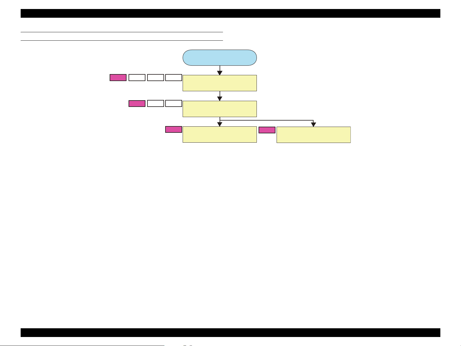
EPSON AcuLaser M2000D/M2000DN/M2010D/M2010DN Revision B
DISASSEMBLY FLOWCHART
Start
A1
B1
B2
C1
C2
D1
D2
C3
Developing Unit
(P. 84)
Photoconductor Unit
(P. 84)
Charging Unit
(P. 85)
D3
Transfer Roller
(P. 85)
DISASSEMBLY AND ASSEMBLY Main Unit Disassembly/Reassembly 83
Page 93
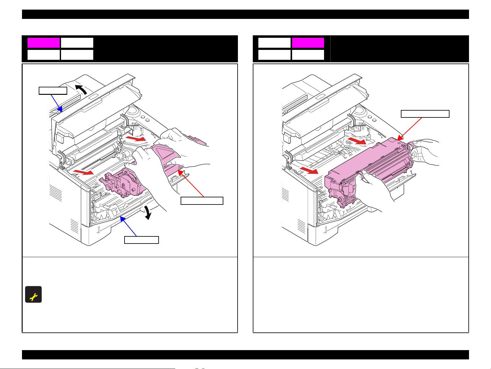
EPSON AcuLaser M2000D/M2000DN/M2010D/M2010DN Revision B
A1 B1
C1 D1
Top Cover
Developing Unit
B2
Photoconductor Unit
C2 D2
Photoconductor Unit
Developing Unit
Front Cover
1. Open the Top Cover.
2. Open the Front Cover.
3. Pull the Developing Unit toward you to remove it.
ADJUSTMENT
The following operations must be carried out after the Developing Unit has been
REQU IRED
replaced with a new one.
1. Install the toner cartridge for initial filling supplied with the Developing Unit.
2. Turn the printer on while holding down [Start/Stop] and [Information] buttons.
The printer will start up in toner filling mode.
3. When the toner filling is completed, remove the toner cartridge for initial filling,
and install the toner cartridge in use.
1. Pull the Photoconductor Unit toward you to remove it.
DISASSEMBLY AND ASSEMBLY Main Unit Disassembly/Reassembly 84
Page 94

EPSON AcuLaser M2000D/M2000DN/M2010D/M2010DN Revision B
C3
Photoconductor Unit
Charging Unit
Charging Unit
Charging Unit
2
Main Plate
Charging Unit
Transfer Roller
D3
Paper Shoot Guide
1
Paper Shoot Guide
Hooks
1. Slide the Paper Shoot Guide to disengage the hooks.
2. Remove the Paper Shoot Guide.
1. While pressing the Main Plate ( ), slide the Charging Unit ( ).
1 2
2. Pull the Charging Unit upward to remove it.
DISASSEMBLY AND ASSEMBLY Main Unit Disassembly/Reassembly 85
Page 95

EPSON AcuLaser M2000D/M2000DN/M2010D/M2010DN Revision B
Shaft
Shaft
Gear
Transfer Shaft Bearings
Transfer Roller
Gear
Lever
3. Pull the Transfer Roller Shafts from the bearings, and remove the Transfer Roller.
4. Remove the gear from the Transfer Roller.
When attaching the Transfer Roller, push the release lever to lift its front end, and put
the gear shaft under the front end of the lever.
DISASSEMBLY AND ASSEMBLY Main Unit Disassembly/Reassembly 86
Page 96

EPSON AcuLaser M2000D/M2000DN/M2010D/M2010DN Revision B
4.3.4 Group 4
CONTENT
Parts/Units to be Disassembled
Paper Feed Roller (Paper Cassette)
Paper Sensor
Separation Roller (Paper Cassette)
Guide
A
B
C
- Bottom of Main Unit -
Paper Sensor
B
Paper Feed Roller (Paper Cassette)
A
C
Separation Roller (Paper Cassette)
DISASSEMBLY AND ASSEMBLY Main Unit Disassembly/Reassembly 87
Page 97

EPSON AcuLaser M2000D/M2000DN/M2010D/M2010DN Revision B
DISASSEMBLY FLOWCHART
Start
A2
C1B1A1
B2
B3
Paper Cassette
(P. 89)
Paper Feed Roller
(Paper Cassette)
Paper Sensor
(P. 90)
(P. 89)
C2
Separation Roller
(Paper Cassette)
(P. 90)
DISASSEMBLY AND ASSEMBLY Main Unit Disassembly/Reassembly 88
Page 98

EPSON AcuLaser M2000D/M2000DN/M2010D/M2010DN Revision B
A1 B1
C1
Paper Cassette
Paper Cassette
A2 B2
Paper Feed Roller
Paper Feed Roller (Paper Cassette)
Feed Shaft
Paper Feed
Roller
Lever
Feed Shaft
Feed Shaft
1. Remove the Paper Cassette.
End of the Shaft
1. Push the lever and remove the Paper Feed Roller.
Match the Feed Shaft end with the oval hole on the Paper Feed Roller.
Oval shape
DISASSEMBLY AND ASSEMBLY Main Unit Disassembly/Reassembly 89
Page 99

EPSON AcuLaser M2000D/M2000DN/M2010D/M2010DN Revision B
Bottom
B3
Connector
Holder
Hooks
Paper Sensor
Paper Sensor
Actuator
Feed Shaft
Separation Roller (Paper Cassette)
C2
Front side
Separation Roller
Bottom Plate
1. Put the printer upside down.
1. Secure the Bottom Plate by pressing it down.
2. Pull the Feed Shaft out in the direction of the arrow.
3. Disengage the two hooks and remove the holder.
4. Remove the actuator from the holder.
5. Disengage the hook and remove the Paper Sensor.
6. Disconnect the connector from the Paper Sensor.
DISASSEMBLY AND ASSEMBLY Main Unit Disassembly/Reassembly 90
Page 100

EPSON AcuLaser M2000D/M2000DN/M2010D/M2010DN Revision B
Back side
Hooks
Spring
Projection
2. Disengage the two hooks from the back of the cassette, and remove the Separation Roller.
Attach the spring to the projection of the separation Roller holder.
DISASSEMBLY AND ASSEMBLY Main Unit Disassembly/Reassembly 91
 Loading...