

Page 1
n
E
Register your instrument!
www.eppendorf.com/myeppendorf
ual075
N)
manual
®
epMotion
5075
Hardware manual
Page 2

©
Copyright
2013 Eppendorf AG, Hamburg. No part of this publication may be reproduced without the prior
permission of the copyright owner.
Trademarks
Eppendorf
®
, the Epppendorf logo, epMotion®, Eppendorf Tubes ®, and epT.I.P.S.® are registered
trademarks of Eppendorf AG.
®
LightCycler
and MagNA Pure® are registered trademarks of Roche Diagnostics.
epMotion VAC sealing foil U.S. Pat. No. 6,666,978
epMotion optical sensor U.S. Pat. No. 6,819,437
epMotion gripping tool U.S. Pat. No. 7,462,327
Registered trademarks are not marked in all cases with
®
or ™ in this manual.
The software of the device (firmware) contains open source software. License information is available on
request from Eppendorf AG.
Only for epMotion M5073, M5073c, 5075m and 5075mc: Limited Use Label License NOTICE TO
PURCHASER; LIMITED LICENSE FOR RESEARCH USE ONLY.
This product and its use may be covered by one or more patents owned by Gen-Probe Incorporated. The
purchase price for this product includes only limited, nontransferable rights under certain claims of certain
patents owned by Gen-Probe Incorporated to use this product for research purposes only. No other rights
are conveyed. Purchaser is not granted any rights under patents of Gen-Probe Incorporated to use this
product for any commercial use. Further information regarding purchasing a license under patents of
Gen-Probe Incorporated to use this product for any other purposes, including, without limitation, for
commercial use, may be obtained by contacting Gen-Probe Incorporated, Attn: Business Development
Department, 10210 Genetic Center Drive, San Diego, California 92121-4362, U.S.A.
5075 900.840-00/062013
Page 3

Table of contents
epMotion
®
5075
English (EN)
Table of contents
1 Operating instructions . . . . . . . . . . . . . . . . . . . . . . . . . . . . . . . . . . . . . . . . . . . . . . . . . . . . . . . . . . . . . . 9
1.1 Using this manual . . . . . . . . . . . . . . . . . . . . . . . . . . . . . . . . . . . . . . . . . . . . . . . . . . . . . . . . . . . . . 9
1.2 Danger symbols and danger levels . . . . . . . . . . . . . . . . . . . . . . . . . . . . . . . . . . . . . . . . . . . . . . . . 9
1.2.1 Danger symbols . . . . . . . . . . . . . . . . . . . . . . . . . . . . . . . . . . . . . . . . . . . . . . . . . . . . . . . 9
1.2.2 Danger levels. . . . . . . . . . . . . . . . . . . . . . . . . . . . . . . . . . . . . . . . . . . . . . . . . . . . . . . . . . 9
1.3 Symbols used . . . . . . . . . . . . . . . . . . . . . . . . . . . . . . . . . . . . . . . . . . . . . . . . . . . . . . . . . . . . . . . 10
1.4 Abbreviations used . . . . . . . . . . . . . . . . . . . . . . . . . . . . . . . . . . . . . . . . . . . . . . . . . . . . . . . . . . . 10
1.5 Glossary. . . . . . . . . . . . . . . . . . . . . . . . . . . . . . . . . . . . . . . . . . . . . . . . . . . . . . . . . . . . . . . . . . . . 11
1.6 Revision history. . . . . . . . . . . . . . . . . . . . . . . . . . . . . . . . . . . . . . . . . . . . . . . . . . . . . . . . . . . . . . 15
2 Product description . . . . . . . . . . . . . . . . . . . . . . . . . . . . . . . . . . . . . . . . . . . . . . . . . . . . . . . . . . . . . . . 17
2.1 Main illustration . . . . . . . . . . . . . . . . . . . . . . . . . . . . . . . . . . . . . . . . . . . . . . . . . . . . . . . . . . . . . 17
2.1.1 epMotion 5075 . . . . . . . . . . . . . . . . . . . . . . . . . . . . . . . . . . . . . . . . . . . . . . . . . . . . . . . 17
2.1.2 Interfaces. . . . . . . . . . . . . . . . . . . . . . . . . . . . . . . . . . . . . . . . . . . . . . . . . . . . . . . . . . . . 18
2.1.3 MultiCon . . . . . . . . . . . . . . . . . . . . . . . . . . . . . . . . . . . . . . . . . . . . . . . . . . . . . . . . . . . . 18
2.2 Delivery package. . . . . . . . . . . . . . . . . . . . . . . . . . . . . . . . . . . . . . . . . . . . . . . . . . . . . . . . . . . . . 19
2.2.1 epMotion 5075l and epMotion 5075lg . . . . . . . . . . . . . . . . . . . . . . . . . . . . . . . . . . . . . 19
2.2.2 epMotion 5075t and epMotion 5075tg . . . . . . . . . . . . . . . . . . . . . . . . . . . . . . . . . . . . . 19
2.2.3 epMotion 5075v and epMotion 5075vg . . . . . . . . . . . . . . . . . . . . . . . . . . . . . . . . . . . . 19
2.2.4 epMotion 5075vt and epMotion 5075vtg . . . . . . . . . . . . . . . . . . . . . . . . . . . . . . . . . . . 20
2.2.5 epMotion 5075m and epMotion 5075mg . . . . . . . . . . . . . . . . . . . . . . . . . . . . . . . . . . . 20
2.2.6 Accessories for all versions of the epMotion . . . . . . . . . . . . . . . . . . . . . . . . . . . . . . . . 21
2.2.7 Accessories for epMotion with epBlue ID. . . . . . . . . . . . . . . . . . . . . . . . . . . . . . . . . . . 21
2.2.8 Accessories for epMotion with epBlue GxP . . . . . . . . . . . . . . . . . . . . . . . . . . . . . . . . . 21
2.3 Features. . . . . . . . . . . . . . . . . . . . . . . . . . . . . . . . . . . . . . . . . . . . . . . . . . . . . . . . . . . . . . . . . . . . 22
2.3.1 Function . . . . . . . . . . . . . . . . . . . . . . . . . . . . . . . . . . . . . . . . . . . . . . . . . . . . . . . . . . . . 22
2.3.2 Gripper . . . . . . . . . . . . . . . . . . . . . . . . . . . . . . . . . . . . . . . . . . . . . . . . . . . . . . . . . . . . . 22
2.3.3 Thermal module . . . . . . . . . . . . . . . . . . . . . . . . . . . . . . . . . . . . . . . . . . . . . . . . . . . . . . 22
2.3.4 Thermomixer. . . . . . . . . . . . . . . . . . . . . . . . . . . . . . . . . . . . . . . . . . . . . . . . . . . . . . . . . 22
2.3.5 Magnetic separation . . . . . . . . . . . . . . . . . . . . . . . . . . . . . . . . . . . . . . . . . . . . . . . . . . . 23
2.3.6 Vacuum unit . . . . . . . . . . . . . . . . . . . . . . . . . . . . . . . . . . . . . . . . . . . . . . . . . . . . . . . . . 23
2.3.7 CleanCap . . . . . . . . . . . . . . . . . . . . . . . . . . . . . . . . . . . . . . . . . . . . . . . . . . . . . . . . . . . . 23
3
3 Safety. . . . . . . . . . . . . . . . . . . . . . . . . . . . . . . . . . . . . . . . . . . . . . . . . . . . . . . . . . . . . . . . . . . . . . . . . . . 25
3.1 Intended use . . . . . . . . . . . . . . . . . . . . . . . . . . . . . . . . . . . . . . . . . . . . . . . . . . . . . . . . . . . . . . . . 25
3.1.1 Intended use of the epMotion 5075 . . . . . . . . . . . . . . . . . . . . . . . . . . . . . . . . . . . . . . . 25
3.2 User profile . . . . . . . . . . . . . . . . . . . . . . . . . . . . . . . . . . . . . . . . . . . . . . . . . . . . . . . . . . . . . . . . . 25
3.3 Information on product liability . . . . . . . . . . . . . . . . . . . . . . . . . . . . . . . . . . . . . . . . . . . . . . . . . 26
3.4 Warnings for intended use . . . . . . . . . . . . . . . . . . . . . . . . . . . . . . . . . . . . . . . . . . . . . . . . . . . . . 26
3.5 Hazard symbols and safety devices on the device . . . . . . . . . . . . . . . . . . . . . . . . . . . . . . . . . . . 29
4 Installation . . . . . . . . . . . . . . . . . . . . . . . . . . . . . . . . . . . . . . . . . . . . . . . . . . . . . . . . . . . . . . . . . . . . . . 31
4.1 Selecting the location . . . . . . . . . . . . . . . . . . . . . . . . . . . . . . . . . . . . . . . . . . . . . . . . . . . . . . . . . 31
4.2 Installing the device . . . . . . . . . . . . . . . . . . . . . . . . . . . . . . . . . . . . . . . . . . . . . . . . . . . . . . . . . . 31
Page 4

Table of contents
®
4
epMotion
5075
English (EN)
5 Hardware. . . . . . . . . . . . . . . . . . . . . . . . . . . . . . . . . . . . . . . . . . . . . . . . . . . . . . . . . . . . . . . . . . . . . . . . 33
5.1 Worktable . . . . . . . . . . . . . . . . . . . . . . . . . . . . . . . . . . . . . . . . . . . . . . . . . . . . . . . . . . . . . . . . . . 33
5.1.1 Layout of the epMotion 5075I worktable . . . . . . . . . . . . . . . . . . . . . . . . . . . . . . . . . . . 33
5.1.2 Layout of the epMotion 5075t worktable . . . . . . . . . . . . . . . . . . . . . . . . . . . . . . . . . . . 33
5.1.3 Layout of the epMotion 5075v worktable . . . . . . . . . . . . . . . . . . . . . . . . . . . . . . . . . . . 34
5.1.4 Layout of the epMotion 5075vt worktable . . . . . . . . . . . . . . . . . . . . . . . . . . . . . . . . . . 34
5.1.5 Layout of the epMotion 5075m worktable . . . . . . . . . . . . . . . . . . . . . . . . . . . . . . . . . . 35
5.2 Optical sensor . . . . . . . . . . . . . . . . . . . . . . . . . . . . . . . . . . . . . . . . . . . . . . . . . . . . . . . . . . . . . . . 36
5.3 Thermal module . . . . . . . . . . . . . . . . . . . . . . . . . . . . . . . . . . . . . . . . . . . . . . . . . . . . . . . . . . . . . 37
5.3.1 Safety notes . . . . . . . . . . . . . . . . . . . . . . . . . . . . . . . . . . . . . . . . . . . . . . . . . . . . . . . . . . 37
5.3.2 Configuration . . . . . . . . . . . . . . . . . . . . . . . . . . . . . . . . . . . . . . . . . . . . . . . . . . . . . . . . 37
5.3.3 Equipping the thermal module . . . . . . . . . . . . . . . . . . . . . . . . . . . . . . . . . . . . . . . . . . . 38
5.4 Thermomixer. . . . . . . . . . . . . . . . . . . . . . . . . . . . . . . . . . . . . . . . . . . . . . . . . . . . . . . . . . . . . . . . 39
5.4.1 Safety notes . . . . . . . . . . . . . . . . . . . . . . . . . . . . . . . . . . . . . . . . . . . . . . . . . . . . . . . . . . 39
5.4.2 Configuration . . . . . . . . . . . . . . . . . . . . . . . . . . . . . . . . . . . . . . . . . . . . . . . . . . . . . . . . 39
5.4.3 Equipping the thermomixer . . . . . . . . . . . . . . . . . . . . . . . . . . . . . . . . . . . . . . . . . . . . . 40
5.5 Magnet finger module. . . . . . . . . . . . . . . . . . . . . . . . . . . . . . . . . . . . . . . . . . . . . . . . . . . . . . . . . 41
5.5.1 Configuration . . . . . . . . . . . . . . . . . . . . . . . . . . . . . . . . . . . . . . . . . . . . . . . . . . . . . . . . 41
5.5.2 Equipping the magnet finger module . . . . . . . . . . . . . . . . . . . . . . . . . . . . . . . . . . . . . . 41
5.6 Vacuum unit . . . . . . . . . . . . . . . . . . . . . . . . . . . . . . . . . . . . . . . . . . . . . . . . . . . . . . . . . . . . . . . . 42
5.6.1 Vac Frame vacuum frame . . . . . . . . . . . . . . . . . . . . . . . . . . . . . . . . . . . . . . . . . . . . . . . 42
5.6.2 VAC Lid . . . . . . . . . . . . . . . . . . . . . . . . . . . . . . . . . . . . . . . . . . . . . . . . . . . . . . . . . . . . . 43
5.6.3 Silicone mat for VAC Lid . . . . . . . . . . . . . . . . . . . . . . . . . . . . . . . . . . . . . . . . . . . . . . . . 43
5.6.4 Vac Thermo Lid . . . . . . . . . . . . . . . . . . . . . . . . . . . . . . . . . . . . . . . . . . . . . . . . . . . . . . . 44
5.6.5 Elution plate adapter . . . . . . . . . . . . . . . . . . . . . . . . . . . . . . . . . . . . . . . . . . . . . . . . . . . 45
5.6.6 Loading the vacuum unit . . . . . . . . . . . . . . . . . . . . . . . . . . . . . . . . . . . . . . . . . . . . . . . 46
5.7 CleanCap . . . . . . . . . . . . . . . . . . . . . . . . . . . . . . . . . . . . . . . . . . . . . . . . . . . . . . . . . . . . . . . . . . . 47
5.7.1 HEPA filter. . . . . . . . . . . . . . . . . . . . . . . . . . . . . . . . . . . . . . . . . . . . . . . . . . . . . . . . . . . 47
5.7.2 UV lamp . . . . . . . . . . . . . . . . . . . . . . . . . . . . . . . . . . . . . . . . . . . . . . . . . . . . . . . . . . . . 48
5.8 Barcode reader . . . . . . . . . . . . . . . . . . . . . . . . . . . . . . . . . . . . . . . . . . . . . . . . . . . . . . . . . . . . . . 49
5.9 Tools . . . . . . . . . . . . . . . . . . . . . . . . . . . . . . . . . . . . . . . . . . . . . . . . . . . . . . . . . . . . . . . . . . . . . . 50
5.9.1 Dispensing Tools . . . . . . . . . . . . . . . . . . . . . . . . . . . . . . . . . . . . . . . . . . . . . . . . . . . . . . 50
5.9.2 Gripper . . . . . . . . . . . . . . . . . . . . . . . . . . . . . . . . . . . . . . . . . . . . . . . . . . . . . . . . . . . . . 51
6 Dispensing liquids . . . . . . . . . . . . . . . . . . . . . . . . . . . . . . . . . . . . . . . . . . . . . . . . . . . . . . . . . . . . . . . . 53
6.1 Basic procedure for dispensing . . . . . . . . . . . . . . . . . . . . . . . . . . . . . . . . . . . . . . . . . . . . . . . . . 53
6.1.1 Operating principle of dispensing tools . . . . . . . . . . . . . . . . . . . . . . . . . . . . . . . . . . . . 53
6.1.2 Liquid aspiration up to the remaining volume . . . . . . . . . . . . . . . . . . . . . . . . . . . . . . . 54
6.1.3 Bottom tolerance . . . . . . . . . . . . . . . . . . . . . . . . . . . . . . . . . . . . . . . . . . . . . . . . . . . . . . 54
6.1.4 Transporting and dispensing liquid . . . . . . . . . . . . . . . . . . . . . . . . . . . . . . . . . . . . . . . 55
6.2 Dispensing modes. . . . . . . . . . . . . . . . . . . . . . . . . . . . . . . . . . . . . . . . . . . . . . . . . . . . . . . . . . . . 56
6.2.1 Dispensing mode: Pipette . . . . . . . . . . . . . . . . . . . . . . . . . . . . . . . . . . . . . . . . . . . . . . . 56
6.2.2 Dispensing mode: Multidispense . . . . . . . . . . . . . . . . . . . . . . . . . . . . . . . . . . . . . . . . . 56
6.2.3 Mixing . . . . . . . . . . . . . . . . . . . . . . . . . . . . . . . . . . . . . . . . . . . . . . . . . . . . . . . . . . . . . . 57
6.3 Special features. . . . . . . . . . . . . . . . . . . . . . . . . . . . . . . . . . . . . . . . . . . . . . . . . . . . . . . . . . . . . . 58
6.3.1 Liquid aspiration from bottom of vessel . . . . . . . . . . . . . . . . . . . . . . . . . . . . . . . . . . . . 58
6.3.2 Liquid aspiration from high vessels . . . . . . . . . . . . . . . . . . . . . . . . . . . . . . . . . . . . . . . 59
6.3.3 Liquid dispensing at the height of the vessel edge. . . . . . . . . . . . . . . . . . . . . . . . . . . . 60
6.3.4 Liquid aspiration from a filter plate . . . . . . . . . . . . . . . . . . . . . . . . . . . . . . . . . . . . . . . 60
Page 5

Table of contents
®
epMotion
5075
English (EN)
7 Labware – vessels, plates and pipette tips . . . . . . . . . . . . . . . . . . . . . . . . . . . . . . . . . . . . . . . . . . . . . 61
7.1 Tubes. . . . . . . . . . . . . . . . . . . . . . . . . . . . . . . . . . . . . . . . . . . . . . . . . . . . . . . . . . . . . . . . . . . . . . 61
7.2 Plates. . . . . . . . . . . . . . . . . . . . . . . . . . . . . . . . . . . . . . . . . . . . . . . . . . . . . . . . . . . . . . . . . . . . . . 62
7.2.1 Deepwell plates . . . . . . . . . . . . . . . . . . . . . . . . . . . . . . . . . . . . . . . . . . . . . . . . . . . . . . . 62
7.2.2 Microplates . . . . . . . . . . . . . . . . . . . . . . . . . . . . . . . . . . . . . . . . . . . . . . . . . . . . . . . . . . 63
7.2.3 Filter plates . . . . . . . . . . . . . . . . . . . . . . . . . . . . . . . . . . . . . . . . . . . . . . . . . . . . . . . . . . 63
7.2.4 Channeling plate 96 . . . . . . . . . . . . . . . . . . . . . . . . . . . . . . . . . . . . . . . . . . . . . . . . . . . 63
7.2.5 PCR plates . . . . . . . . . . . . . . . . . . . . . . . . . . . . . . . . . . . . . . . . . . . . . . . . . . . . . . . . . . . 64
7.2.6 Tube plates . . . . . . . . . . . . . . . . . . . . . . . . . . . . . . . . . . . . . . . . . . . . . . . . . . . . . . . . . . 64
7.3 Reservoirs . . . . . . . . . . . . . . . . . . . . . . . . . . . . . . . . . . . . . . . . . . . . . . . . . . . . . . . . . . . . . . . . . . 65
7.4 epT.I.P.S. Motion . . . . . . . . . . . . . . . . . . . . . . . . . . . . . . . . . . . . . . . . . . . . . . . . . . . . . . . . . . . . . 66
7.4.1 epT.I.P.S. Motion Racks. . . . . . . . . . . . . . . . . . . . . . . . . . . . . . . . . . . . . . . . . . . . . . . . . 67
7.4.2 epT.I.P.S. Motion Reloads . . . . . . . . . . . . . . . . . . . . . . . . . . . . . . . . . . . . . . . . . . . . . . . 68
7.4.3 Tip holder for epT.I.P.S. Motion Reloads . . . . . . . . . . . . . . . . . . . . . . . . . . . . . . . . . . . 69
7.4.4 epT.I.P.S. Motion SafeRacks . . . . . . . . . . . . . . . . . . . . . . . . . . . . . . . . . . . . . . . . . . . . . 70
8 Labware accessories . . . . . . . . . . . . . . . . . . . . . . . . . . . . . . . . . . . . . . . . . . . . . . . . . . . . . . . . . . . . . . 71
8.1 Racks . . . . . . . . . . . . . . . . . . . . . . . . . . . . . . . . . . . . . . . . . . . . . . . . . . . . . . . . . . . . . . . . . . . . . . 71
8.1.1 Racks for 24 vessels . . . . . . . . . . . . . . . . . . . . . . . . . . . . . . . . . . . . . . . . . . . . . . . . . . . 71
8.1.2 Rack for 96 vessels . . . . . . . . . . . . . . . . . . . . . . . . . . . . . . . . . . . . . . . . . . . . . . . . . . . . 72
8.1.3 Rack LC . . . . . . . . . . . . . . . . . . . . . . . . . . . . . . . . . . . . . . . . . . . . . . . . . . . . . . . . . . . . . 73
8.1.4 Thermorack and Rack 0.5/1.5/2.0 mL . . . . . . . . . . . . . . . . . . . . . . . . . . . . . . . . . . . . . . 73
8.1.5 PrepRack . . . . . . . . . . . . . . . . . . . . . . . . . . . . . . . . . . . . . . . . . . . . . . . . . . . . . . . . . . . . 74
8.1.6 ReagentRack . . . . . . . . . . . . . . . . . . . . . . . . . . . . . . . . . . . . . . . . . . . . . . . . . . . . . . . . . 75
8.1.7 Reservoir Rack . . . . . . . . . . . . . . . . . . . . . . . . . . . . . . . . . . . . . . . . . . . . . . . . . . . . . . . 76
8.1.8 ReservoirRack 3 . . . . . . . . . . . . . . . . . . . . . . . . . . . . . . . . . . . . . . . . . . . . . . . . . . . . . . 77
8.1.9 Reservoir Rack modules . . . . . . . . . . . . . . . . . . . . . . . . . . . . . . . . . . . . . . . . . . . . . . . . 77
8.2 Adapters . . . . . . . . . . . . . . . . . . . . . . . . . . . . . . . . . . . . . . . . . . . . . . . . . . . . . . . . . . . . . . . . . . . 80
8.2.1 Height adapter . . . . . . . . . . . . . . . . . . . . . . . . . . . . . . . . . . . . . . . . . . . . . . . . . . . . . . . 80
8.2.2 Vac holder vacuum holder . . . . . . . . . . . . . . . . . . . . . . . . . . . . . . . . . . . . . . . . . . . . . . 81
8.2.3 Thermoadapter . . . . . . . . . . . . . . . . . . . . . . . . . . . . . . . . . . . . . . . . . . . . . . . . . . . . . . . 81
8.2.4 Thermoadapter LC samples . . . . . . . . . . . . . . . . . . . . . . . . . . . . . . . . . . . . . . . . . . . . . 82
8.2.5 Thermoadapter Frosty. . . . . . . . . . . . . . . . . . . . . . . . . . . . . . . . . . . . . . . . . . . . . . . . . . 82
8.3 Thermoblocks and Thermoadapters for PCR plates . . . . . . . . . . . . . . . . . . . . . . . . . . . . . . . . . . 83
8.3.1 Equipping the thermoblock with 0.2 mL vessels . . . . . . . . . . . . . . . . . . . . . . . . . . . . . 83
8.4 Waste container . . . . . . . . . . . . . . . . . . . . . . . . . . . . . . . . . . . . . . . . . . . . . . . . . . . . . . . . . . . . . 84
8.4.1 Waste container . . . . . . . . . . . . . . . . . . . . . . . . . . . . . . . . . . . . . . . . . . . . . . . . . . . . . . 84
8.4.2 Waste funnel . . . . . . . . . . . . . . . . . . . . . . . . . . . . . . . . . . . . . . . . . . . . . . . . . . . . . . . . . 84
8.4.3 LiquidWasteTub with lid . . . . . . . . . . . . . . . . . . . . . . . . . . . . . . . . . . . . . . . . . . . . . . . . 85
5
Page 6

Table of contents
®
6
epMotion
5075
English (EN)
9 Operation . . . . . . . . . . . . . . . . . . . . . . . . . . . . . . . . . . . . . . . . . . . . . . . . . . . . . . . . . . . . . . . . . . . . . . . 87
9.1 First steps . . . . . . . . . . . . . . . . . . . . . . . . . . . . . . . . . . . . . . . . . . . . . . . . . . . . . . . . . . . . . . . . . . 87
9.1.1 Switching on the epMotion . . . . . . . . . . . . . . . . . . . . . . . . . . . . . . . . . . . . . . . . . . . . . . 87
9.1.2 Using the MultiCon . . . . . . . . . . . . . . . . . . . . . . . . . . . . . . . . . . . . . . . . . . . . . . . . . . . . 87
9.1.3 Using the epMotion. . . . . . . . . . . . . . . . . . . . . . . . . . . . . . . . . . . . . . . . . . . . . . . . . . . . 88
9.2 Loading the worktable . . . . . . . . . . . . . . . . . . . . . . . . . . . . . . . . . . . . . . . . . . . . . . . . . . . . . . . . 88
9.2.1 Display the loading . . . . . . . . . . . . . . . . . . . . . . . . . . . . . . . . . . . . . . . . . . . . . . . . . . . . 88
9.2.2 Positioning tools on the worktable . . . . . . . . . . . . . . . . . . . . . . . . . . . . . . . . . . . . . . . . 89
9.2.3 Positioning the epT.I.P.S. Motion on the worktable . . . . . . . . . . . . . . . . . . . . . . . . . . . 91
9.2.4 Positioning the waste container on the worktable . . . . . . . . . . . . . . . . . . . . . . . . . . . . 91
9.2.5 Positioning labware on the worktable. . . . . . . . . . . . . . . . . . . . . . . . . . . . . . . . . . . . . . 92
9.3 Executing an application. . . . . . . . . . . . . . . . . . . . . . . . . . . . . . . . . . . . . . . . . . . . . . . . . . . . . . . 93
9.3.1 Performing a test run . . . . . . . . . . . . . . . . . . . . . . . . . . . . . . . . . . . . . . . . . . . . . . . . . . 93
9.3.2 Starting the application . . . . . . . . . . . . . . . . . . . . . . . . . . . . . . . . . . . . . . . . . . . . . . . . . 94
9.3.3 Controlling the application run . . . . . . . . . . . . . . . . . . . . . . . . . . . . . . . . . . . . . . . . . . . 94
9.4 Completing your work. . . . . . . . . . . . . . . . . . . . . . . . . . . . . . . . . . . . . . . . . . . . . . . . . . . . . . . . . 96
9.4.1 Cleaning up the worktable . . . . . . . . . . . . . . . . . . . . . . . . . . . . . . . . . . . . . . . . . . . . . . 96
9.4.2 Switching off the epMotion . . . . . . . . . . . . . . . . . . . . . . . . . . . . . . . . . . . . . . . . . . . . . . 96
10 Maintenance . . . . . . . . . . . . . . . . . . . . . . . . . . . . . . . . . . . . . . . . . . . . . . . . . . . . . . . . . . . . . . . . . . . . . 97
10.1 Decontamination and cleaning . . . . . . . . . . . . . . . . . . . . . . . . . . . . . . . . . . . . . . . . . . . . . . . . . . 97
10.1.1 Carrying out wipe decontamination . . . . . . . . . . . . . . . . . . . . . . . . . . . . . . . . . . . . . . . 99
10.1.2 Carrying out spray decontamination. . . . . . . . . . . . . . . . . . . . . . . . . . . . . . . . . . . . . . 100
10.1.3 Carrying out UV irradiation. . . . . . . . . . . . . . . . . . . . . . . . . . . . . . . . . . . . . . . . . . . . . 100
10.1.4 Autoclaving . . . . . . . . . . . . . . . . . . . . . . . . . . . . . . . . . . . . . . . . . . . . . . . . . . . . . . . . . 100
10.2 Decontamination before shipment . . . . . . . . . . . . . . . . . . . . . . . . . . . . . . . . . . . . . . . . . . . . . . 101
10.3 Servicing the device . . . . . . . . . . . . . . . . . . . . . . . . . . . . . . . . . . . . . . . . . . . . . . . . . . . . . . . . . 101
10.4 Servicing the vacuum unit . . . . . . . . . . . . . . . . . . . . . . . . . . . . . . . . . . . . . . . . . . . . . . . . . . . . 101
10.4.1 Replacing the seals of the vacuum unit . . . . . . . . . . . . . . . . . . . . . . . . . . . . . . . . . . . 101
10.4.2 Replacing the silicone mat of the vacuum lid . . . . . . . . . . . . . . . . . . . . . . . . . . . . . . . 101
10.5 Fuses . . . . . . . . . . . . . . . . . . . . . . . . . . . . . . . . . . . . . . . . . . . . . . . . . . . . . . . . . . . . . . . . . . . . . 102
10.6 Carrying out firmware updates . . . . . . . . . . . . . . . . . . . . . . . . . . . . . . . . . . . . . . . . . . . . . . . . . 102
10.7 Checking the dispensing volume . . . . . . . . . . . . . . . . . . . . . . . . . . . . . . . . . . . . . . . . . . . . . . . 102
10.8 Maintaining the dispensing tools . . . . . . . . . . . . . . . . . . . . . . . . . . . . . . . . . . . . . . . . . . . . . . . 103
10.8.1 Exchanging the sealing rings on the eight-channel dispensing tool . . . . . . . . . . . . . 103
10.9 Customer service functions. . . . . . . . . . . . . . . . . . . . . . . . . . . . . . . . . . . . . . . . . . . . . . . . . . . . 104
11 Troubleshooting . . . . . . . . . . . . . . . . . . . . . . . . . . . . . . . . . . . . . . . . . . . . . . . . . . . . . . . . . . . . . . . . . 105
11.1 Error search . . . . . . . . . . . . . . . . . . . . . . . . . . . . . . . . . . . . . . . . . . . . . . . . . . . . . . . . . . . . . . . 105
11.2 General errors . . . . . . . . . . . . . . . . . . . . . . . . . . . . . . . . . . . . . . . . . . . . . . . . . . . . . . . . . . . . . . 106
11.2.1 Optical sensor errors . . . . . . . . . . . . . . . . . . . . . . . . . . . . . . . . . . . . . . . . . . . . . . . . . . 106
11.2.2 Dispensing errors . . . . . . . . . . . . . . . . . . . . . . . . . . . . . . . . . . . . . . . . . . . . . . . . . . . . 107
11.2.3 Software errors . . . . . . . . . . . . . . . . . . . . . . . . . . . . . . . . . . . . . . . . . . . . . . . . . . . . . . 107
12 Transport, storage and disposal . . . . . . . . . . . . . . . . . . . . . . . . . . . . . . . . . . . . . . . . . . . . . . . . . . . . 109
12.1 Transport. . . . . . . . . . . . . . . . . . . . . . . . . . . . . . . . . . . . . . . . . . . . . . . . . . . . . . . . . . . . . . . . . . 109
12.2 Storage . . . . . . . . . . . . . . . . . . . . . . . . . . . . . . . . . . . . . . . . . . . . . . . . . . . . . . . . . . . . . . . . . . . 109
12.3 Disposal. . . . . . . . . . . . . . . . . . . . . . . . . . . . . . . . . . . . . . . . . . . . . . . . . . . . . . . . . . . . . . . . . . . 110
Page 7

Table of contents
®
epMotion
5075
English (EN)
13 Technical data. . . . . . . . . . . . . . . . . . . . . . . . . . . . . . . . . . . . . . . . . . . . . . . . . . . . . . . . . . . . . . . . . . . 111
13.1 Power supply. . . . . . . . . . . . . . . . . . . . . . . . . . . . . . . . . . . . . . . . . . . . . . . . . . . . . . . . . . . . . . . 111
13.2 Ambient conditions . . . . . . . . . . . . . . . . . . . . . . . . . . . . . . . . . . . . . . . . . . . . . . . . . . . . . . . . . . 111
13.3 Weight/dimensions . . . . . . . . . . . . . . . . . . . . . . . . . . . . . . . . . . . . . . . . . . . . . . . . . . . . . . . . . . 111
13.4 Noise level. . . . . . . . . . . . . . . . . . . . . . . . . . . . . . . . . . . . . . . . . . . . . . . . . . . . . . . . . . . . . . . . . 111
13.5 Interfaces. . . . . . . . . . . . . . . . . . . . . . . . . . . . . . . . . . . . . . . . . . . . . . . . . . . . . . . . . . . . . . . . . . 112
13.6 MultiCon . . . . . . . . . . . . . . . . . . . . . . . . . . . . . . . . . . . . . . . . . . . . . . . . . . . . . . . . . . . . . . . . . . 112
13.7 Additional specifications . . . . . . . . . . . . . . . . . . . . . . . . . . . . . . . . . . . . . . . . . . . . . . . . . . . . . . 112
13.7.1 Optical sensor . . . . . . . . . . . . . . . . . . . . . . . . . . . . . . . . . . . . . . . . . . . . . . . . . . . . . . . 112
13.7.2 Carrier . . . . . . . . . . . . . . . . . . . . . . . . . . . . . . . . . . . . . . . . . . . . . . . . . . . . . . . . . . . . . 112
13.7.3 Gripper . . . . . . . . . . . . . . . . . . . . . . . . . . . . . . . . . . . . . . . . . . . . . . . . . . . . . . . . . . . . 112
13.8 Enhancements. . . . . . . . . . . . . . . . . . . . . . . . . . . . . . . . . . . . . . . . . . . . . . . . . . . . . . . . . . . . . . 113
13.8.1 Thermal module . . . . . . . . . . . . . . . . . . . . . . . . . . . . . . . . . . . . . . . . . . . . . . . . . . . . . 113
13.8.2 Thermomixer. . . . . . . . . . . . . . . . . . . . . . . . . . . . . . . . . . . . . . . . . . . . . . . . . . . . . . . . 113
13.8.3 Magnet finger module. . . . . . . . . . . . . . . . . . . . . . . . . . . . . . . . . . . . . . . . . . . . . . . . . 113
13.8.4 Vacuum unit . . . . . . . . . . . . . . . . . . . . . . . . . . . . . . . . . . . . . . . . . . . . . . . . . . . . . . . . 113
13.8.5 Barcode reader . . . . . . . . . . . . . . . . . . . . . . . . . . . . . . . . . . . . . . . . . . . . . . . . . . . . . . 114
13.8.6 HEPA filter. . . . . . . . . . . . . . . . . . . . . . . . . . . . . . . . . . . . . . . . . . . . . . . . . . . . . . . . . . 114
13.8.7 UV lamp . . . . . . . . . . . . . . . . . . . . . . . . . . . . . . . . . . . . . . . . . . . . . . . . . . . . . . . . . . . 114
13.9 Dispensing tool errors. . . . . . . . . . . . . . . . . . . . . . . . . . . . . . . . . . . . . . . . . . . . . . . . . . . . . . . . 115
13.9.1 Pipetting . . . . . . . . . . . . . . . . . . . . . . . . . . . . . . . . . . . . . . . . . . . . . . . . . . . . . . . . . . . 115
13.9.2 Dispensing. . . . . . . . . . . . . . . . . . . . . . . . . . . . . . . . . . . . . . . . . . . . . . . . . . . . . . . . . . 116
13.10 Test conditions for dispensing tool errors . . . . . . . . . . . . . . . . . . . . . . . . . . . . . . . . . . . . . . . . 116
7
14 Ordering Information . . . . . . . . . . . . . . . . . . . . . . . . . . . . . . . . . . . . . . . . . . . . . . . . . . . . . . . . . . . . . 117
14.1 Tools . . . . . . . . . . . . . . . . . . . . . . . . . . . . . . . . . . . . . . . . . . . . . . . . . . . . . . . . . . . . . . . . . . . . . 117
14.2 epT.I.P.S. Motion . . . . . . . . . . . . . . . . . . . . . . . . . . . . . . . . . . . . . . . . . . . . . . . . . . . . . . . . . . . . 117
14.3 Plates. . . . . . . . . . . . . . . . . . . . . . . . . . . . . . . . . . . . . . . . . . . . . . . . . . . . . . . . . . . . . . . . . . . . . 119
14.4 Reservoirs . . . . . . . . . . . . . . . . . . . . . . . . . . . . . . . . . . . . . . . . . . . . . . . . . . . . . . . . . . . . . . . . . 119
14.5 Racks . . . . . . . . . . . . . . . . . . . . . . . . . . . . . . . . . . . . . . . . . . . . . . . . . . . . . . . . . . . . . . . . . . . . . 120
14.6 Adapters . . . . . . . . . . . . . . . . . . . . . . . . . . . . . . . . . . . . . . . . . . . . . . . . . . . . . . . . . . . . . . . . . . 121
14.7 Thermoblocks . . . . . . . . . . . . . . . . . . . . . . . . . . . . . . . . . . . . . . . . . . . . . . . . . . . . . . . . . . . . . . 121
14.8 Accessories for the vacuum chamber . . . . . . . . . . . . . . . . . . . . . . . . . . . . . . . . . . . . . . . . . . . . 122
14.9 MagSep kits. . . . . . . . . . . . . . . . . . . . . . . . . . . . . . . . . . . . . . . . . . . . . . . . . . . . . . . . . . . . . . . . 122
14.10 Accessories . . . . . . . . . . . . . . . . . . . . . . . . . . . . . . . . . . . . . . . . . . . . . . . . . . . . . . . . . . . . . . . . 122
14.11 Modification kits and enhancements . . . . . . . . . . . . . . . . . . . . . . . . . . . . . . . . . . . . . . . . . . . . 123
Index . . . . . . . . . . . . . . . . . . . . . . . . . . . . . . . . . . . . . . . . . . . . . . . . . . . . . . . . . . . . . . . . . . . . . . . . . . 124
Page 8

Table of contents
epMotion
8
English (EN)
®
5075
Page 9
Operating instructions
epMotion
English (EN)
1 Operating instructions
1.1 Using this manual
Your epMotion operating manual consists of hardware instructions and software instructions. Short
instructions are available for optional software enhancements.
The operating manual is part of the product.
®
5075
9
The current version of the operating manual can be found on our webpage: www.eppendorf.com
.
Read the operating manual in full before using the device.
Store the operating manual at an easily accessible location.
The device may only be transferred with the operating manual.
If the operating manual is lost, replace it immediately. Please contact Eppendorf AG for further details.
1.2 Danger symbols and danger levels
The safety instructions in this manual appear with the following danger symbols and danger levels:
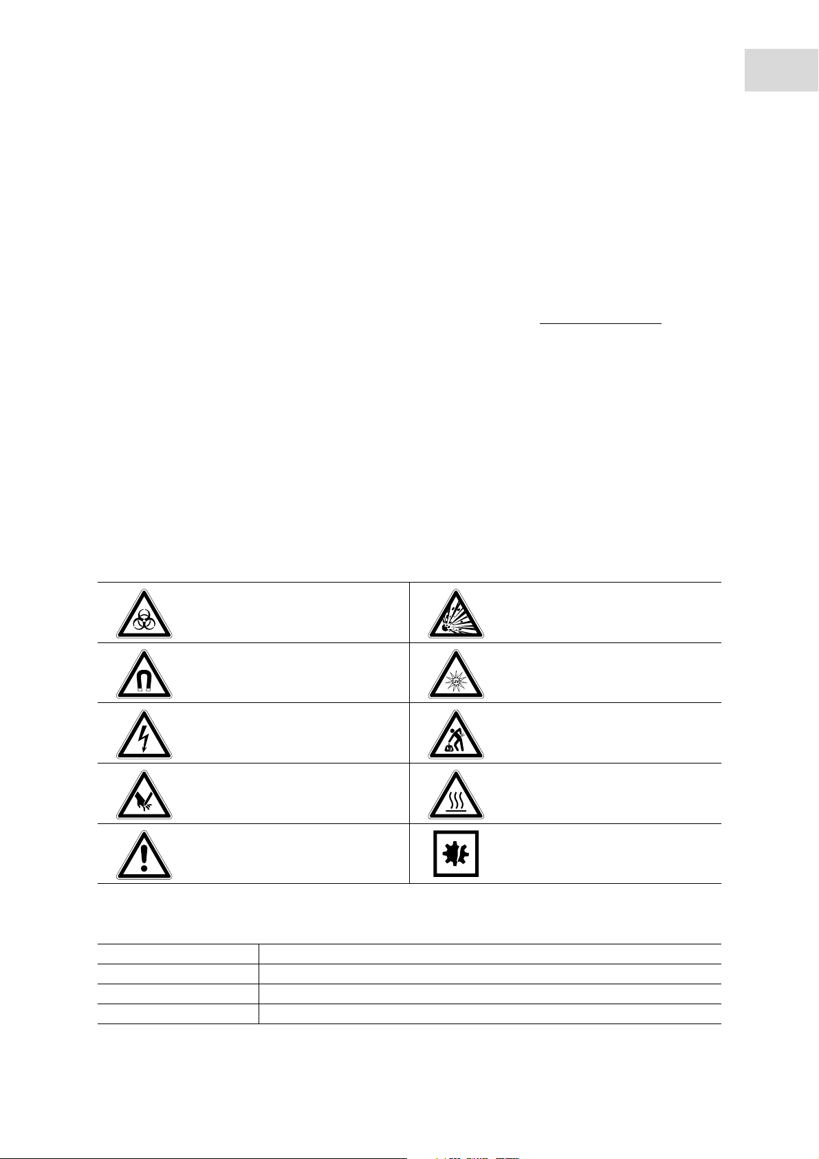
1.2.1 Danger symbols
Biohazard Explosion
Strong magnetic field UV radiation
Electric shock Heavy loads
Cuts Hot surface
Hazard point Material damage
1.2.2 Danger levels
DANGER Will lead to severe injuries or death.
WARN ING May lead to severe injuries or death.
CAUTION May lead to light to moderate injuries.
NOTICE May lead to material damage.
Page 10

10
Operating instructions
epMotion
English (EN)
®
5075
1.3 Symbols used
Depiction Meaning
1.
2.
Actions in the specified order
Actions without a specified order
• List:
Text Display or software texts
Additional information
1.4 Abbreviations used
BCR
Barcode reader
DNA
Deoxyribonucleic acid (DNA)
DWP
Deepwell plate
epT.I.P.S.
eppendorf Totally Integrated Pipetting System
HEPA
High-Efficiency Particulate Air (filter)
LH
Liquid handling
MTP
Micro test plate
PCR
Polymerase chain reaction
PDF
Portable Document Format
TMX
Thermomixer
USB
Universal Serial Bus
UV
Ultraviolet radiation
VAC
Vacuum unit
Page 11

Operating instructions
epMotion
English (EN)
1.5 Glossary
A
Application
Programs for a specific application. An application includes the procedure and the equipping of the
worktable.
B
Barcode reader
Device for scanning a barcode.
C
CleanCap
Optional epMotion equipment. The CleanCap includes a HEPA filter and UV lamp.
®
5075
11
D
Destination labware
Labware that liquid is dispensed into during the application. Destination labware refers to a plate or rack.
Destination position
Position that liquid is dispensed into during the application.
Destination vessel
The vessel into which liquid is dispensed during the application.
Dispensing tool
Tool that aspirates and dispenses liquid. Single-channel dispensing tools and eight-channel dispensing
tools are available for various volume ranges.
E
epBlue
Software for creating and administering applications and labware. The epMotion is controlled using the
software. epBlue is used to manage access to epMotion. epBlue can be expanded. The ID module enables
barcode tracking. The GxP module enables electronic documentation in support of 21 CFR Part 11.
Eppendorf Quality
Eppendorf Quality is an Eppendorf AG purity grade for consumables. Eppendorf Quality meets the
requirements for standard products, e.g., precision, accuracy, wetting behavior and tightness.
epT.I.P.S.® Motion
epMotion pipette tips. Only epT.I.P.S.® Motion can be used on the epMotion for all features. epT.I.P.S.®
Motions are available with or without a filter.
Page 12

12
Operating instructions
®
epMotion
5075
English (EN)
F
Filling volume
Maximum liquid volume of a labware. The epMotion uses the gripper to transport the labware up to the
filling volume. The epMotion aspirates liquid from the labware up to the filling volume. The filling volume is
higher than the working volume.
G
Gripper
Tool that transports labware.
H
Height adapter
Adapter for low labware. The height differences among the labware will be offset to decrease the tool
holder paths, thereby decreasing the run time of the application as well.
HEPA filter
Air filter. The air filter prevents particles such as dust and germs from the environment entering the
epMotion work room.
I
Intermediate labware
Labware that is used to dispense and aspirate liquids during the application.
Intermediate position
Position that is used to dispense and aspirate liquids during the application.
Intermediate vessel
Vessel that is used to dispense and aspirate liquids during the application.
L
Labware
Racks, plates, tips, etc. which are placed on the worktable.
Location
Area on the worktable where the labware is placed.
M
MagSep
System consisting of the magnetic finger module, thermomixer and PrepRack and reagents for nucleic acid
preparation with the epMotion.
MultiCon
epMotion operator panel. You can control your epMotion using the control unit and the epBlue software.
Page 13

Operating instructions
epMotion
English (EN)
P
PCR clean
PCR clean is an Eppendorf AG purity grade for consumables. PCR clean meets the requirements for
standard products, e.g., precision, accuracy, wetting behavior, tightness. PCR clean also meets the
requirements with regard to absence of human DNA, DNase, RNase and PCR inhibitors.
Consumables with the PCR clean purity grade are controlled and certified by an external laboratory.
Certificates are available for downloading from our webpage www.eppendorf.com
.
Procedure
Sequence of commands that are executed one after the other. Part of an application.
R
Rack
Mount for tubes or pipette tips.
®
5075
13
Random error
Precision. Standard deviation of the average value of the dispensed volumes.
Remaining volume
Volume that cannot be aspirated from a vessel. The distance from the pipette tip to the vessel bottom,
defined in the software, and the defined immersion depth of the pipette tip in the liquid, must be observed.
Therefore, the pipette tip cannot aspirate the volume. The remaining volume depends on the vessel
geometry.
Reservoir
Reservoirs are used to hold reagents. Reservoirs are hung in a Reservoir Rack or placed directly on the
worktable.
S
SafeRack
Rack with ep.T.I.P.S. Motion pipette tips. The SafeRack features a partition that prevents the contamination
of adjacent tips. Use the SafeRacks if you would like to use tips several times.
Source labware
Labware that liquid is aspirated from during the application. Source labware refers to a plate or rack.
Source position
Position that liquid is aspirated from during the application.
Source vessel
The vessel from which liquid is aspirated during the application.
Sterile
Sterile is an Eppendorf AG purity grade for consumables. Sterile meets the requirements for standard
products, e.g., precision, accuracy, wetting behavior, tightness. Sterile also meets the requirements with
regard to sterility and freedom from pyrogens.
Page 14

14
Operating instructions
®
epMotion
5075
English (EN)
Systematic error
Accuracy. Deviation of the average value of the dispensed volumes from the selected volume.
T
Thermal module
Thermal module for labware that is integrated in the worktable.
Thermoadapter
Heat-conductive adapter for holding plates.
Thermoblock
A thermoadapter that is permanently connected to a PCR plate or PCR tube.
Thermorack
Temperable rack for smaller vessels, e.g., Safe-Lock tubes for 0.5 mL, 1.5 mL or 2 mL.
V
Vacuum unit
The vacuum unit uses a vacuum to suck liquid from a filter plate. The vacuum unit consists of a vacuum
manifold, vacuum pump and Vac Frame.
Vessel
Tube or single well of a plate.
W
Work volume
Liquid volume of a labware. The epMotion fills a vessel with low levels of contamination up to the working
volume. The working volume is less than the filling volume.
Worktable
Work surface of the epMotion where labware and tools are placed. In the software, the epMotion worktable
is shown as the epBlue worktable.
Page 15

Operating instructions
1.6 Revision history
Revision history of the epMotion 5075 hardware operating manual, order no. 5075 900.840.
Version of the operating manual Date Changes
Version 00 June 2013 Created new
epMotion
English (EN)
®
5075
15
Page 16

16
Operating instructions
®
epMotion
5075
English (EN)
Page 17
Product description
epMotion
English (EN)
2 Product description
2.1 Main illustration
The epMotion 5075 is available with various features. Details of the worktable for your device (see
Worktable on p. 33).
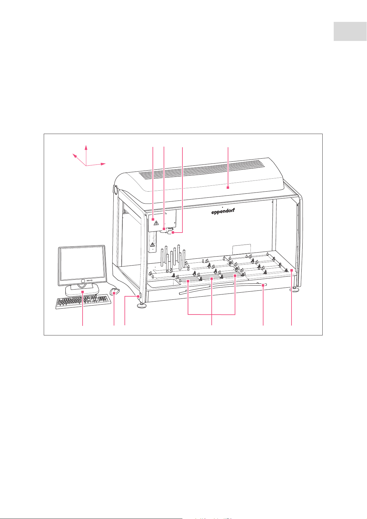
2.1.1 epMotion 5075
Abb. 2-1: Main illustrati on epMotion 5075I
z
y
x
2
1
3
4
®
5075
17
8
10
9
Fig. 2-1: Main illustration epMotion 5075I
1Carrier
The carrier moves in X-direction, Y-direction and
Z-direction.
2 Tool holder
Holds dispensing tools.
epMotio n 5 07 5
7
6
5
6 Front hood
Safety device for protection from movable, UV
radiation parts and contamination.
7 Thermal module (optional)
Plate for heating and cooling labware.
3Optical sensor
Detects levels, tips and labware.
4CleanCap (optional)
contains HEPA filter and UV lamps
5Worktable
Work surface for tools and labware.
8 Mains power switch
9Mouse
10 MultiCon
Control unit used to control the epMotion.
Page 18
18
1
2
3
Product description
®
epMotion
5075
English (EN)
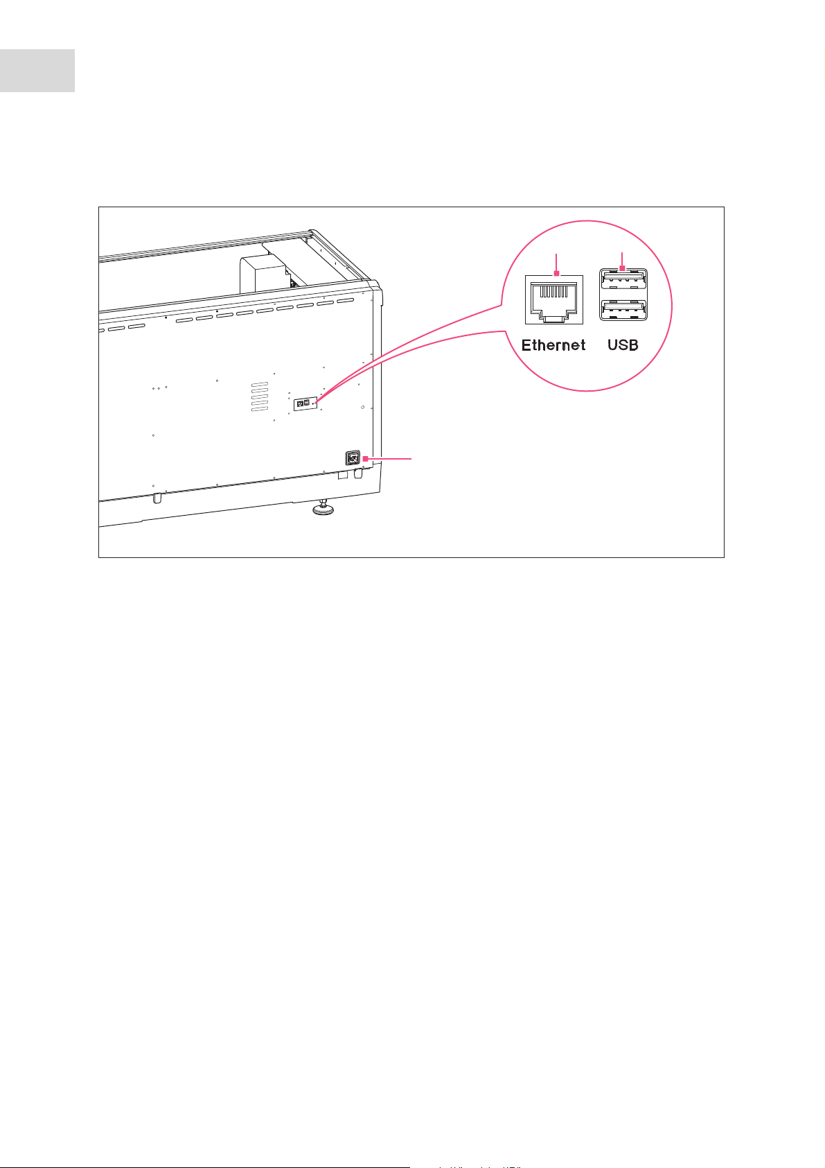
2.1.2 Interfaces
Abb. 2-2: Interfaces epMoti on 5075
Fig. 2-2: Interfaces epMotion 5075
1Ethernet
3 Mains power connection
Connection for the cable to the MultiCon
2USB
Connection for a USB storage medium for
firmware updates.
Only devices which meet the requirements of IEC 950/EN 60950-1 (UL 1950) standards may be connected
to the interfaces.
2.1.3 MultiCon
Information can be found in the operating manual of the MultiCon.
Only devices which meet the requirements of IEC 950/EN 60950-1 (UL 1950) standards may be connected
to the interfaces.
Page 19

Product description
epMotion
English (EN)
2.2 Delivery package
The epMotion is available in various versions. Your device has been equipped according to your
specifications. For some software modules additional accessories are available.
2.2.1 epMotion 5075l and epMotion 5075lg
®
5075
19
Quantity Order no.
(International)
1 5075 000.271 100 V - 240 V, 50 / 60 Hz
or 1 5075 000.275 100 V - 240 V, 50 / 60 Hz
Description
Automated pipetting system epMotion 5075l
main device; with MultiCon, keyboard, mouse,
installed software epBlue
Automated pipetting system epMotion 5075lg
main device; with MultiCon, keyboard, mouse,
installed software epBlue GxP
2.2.2 epMotion 5075t and epMotion 5075tg
Quantity Order no.
(International)
1 5075 000.272 100 V - 240 V, 50 / 60 Hz
or 1 5075 000.276 100 V - 240 V, 50 / 60 Hz
Description
Automated pipetting system epMotion 5075t
main device with thermomixer; with MultiCon, keyboard, mouse,
installed software epBlue
Automated pipetting system epMotion 5075tg
main device with thermomixer; with MultiCon, keyboard, mouse,
installed software epBlue GxP
2.2.3 epMotion 5075v and epMotion 5075vg
Quantity Order no.
(International)
1 5075 000.273 100 V - 240 V, 50 / 60 Hz
or 1 5075 000.277 100 V - 240 V, 50 / 60 Hz
1– Reservoir 400 mL
1 5075 785.005 vacuum frame
1 5075 778.009 adapter for Vac Frame
1 5282 000.018 Gripper
Description
Automated pipetting system epMotion 5075v
main device with vacuum unit; with MultiCon, keyboard, mouse,
installed software epBlue
Automated pipetting system epMotion 5075vg
main device with vacuum unit; with MultiCon, keyboard, mouse,
installed software epBlue GxP
Vac Frame 2
Vac Holder
Page 20

20
Product description
epMotion
English (EN)
®
5075
2.2.4 epMotion 5075vt and epMotion 5075vtg
Quantity Order no.
(International)
1 5075 000.274 100 V - 240 V, 50 / 60 Hz
or 1 5075 000.278 100 V - 240 V, 50 / 60 Hz
1– Reservoir 400 mL
1 5075 785.005 vacuum frame
1 5075 778.009 adapter for Vac Frame
1 5282 000.018 Gripper
Description
Automated pipetting system epMotion 5075vt
main device with vacuum unit and thermomixer; with MultiCon,
keyboard, mouse, installed software epBlue
Automated pipetting system epMotion 5075vtg
main device with vacuum item and thermomixer; with MultiCon,
keyboard, mouse, installed software epBlue GxP
Vac Frame 2
Vac Holder
2.2.5 epMotion 5075m and epMotion 5075mg
Quantity Order no.
(International)
1 5075 000.270 100 V - 240 V, 50 / 60 Hz
or 1 5075 000.279 100 V - 240 V, 50 / 60 Hz
Description
Automated pipetting system epMotion 5075m
main device with magnet finger module and thermomixer; with
MultiCon, keyboard, mouse, installed software epBlue
Automated pipetting system epMotion 5075mg
main device with magnet finger module and thermomixer; with
MultiCon, keyboard, mouse, installed software epBlue GxP
Page 21

2.2.6 Accessories for all versions of the epMotion
Product description
epMotion
®
5075
English (EN)
21
Quantity Order no.
(International)
1 - With USB connection cable
1 - With USB connection cable
1
1 - Compatible with the country where the order was placed or defined
1 - For connecting the MultiCon to a network
1- Tool for transport securing device
1 5075 753.006 Waste box
1 5075 900.840 epMotion 5075
1 5073 900.866 software operating manual epBlue with MultiCon
optional 1 5075 751.607 with HEPA air filter and UV-lamp
optional 2-
-
Description
Mouse
Keyboard
Cable
For connecting the MultiCon to the epMotion
Mains power cable
USB-Ethernet adapter
Operating Manual
CleanCap
UV tube
For epMotion with CleanCap
2.2.7 Accessories for epMotion with epBlue ID
Quantity Order no.
(International)
1
1
–
Barcode reader
Description
USB dongle eLicenser
with hardware key code card
With USB connection cable and table stand
2.2.8 Accessories for epMotion with epBlue GxP
Quantity Order no.
(International)
1
1
1 5075 900.874 epBlue GxP
–
–
Description
USB dongle eLicenser
with hardware key code card
Documentation folder
Folder for certificates and documentation
Operating Manual
Page 22

22
Product description
epMotion
English (EN)
®
5075
2.3 Features
The epMotion 5075 is available with different features. All available features are described in this manual.
2.3.1 Function
The epMotion 5075 is an automatic system for dispensing liquids using dispensing tools and ep.T.I.P.S.
Motion pipette tips.
The epMotion 5075 dispenses liquids in the volume range 1 µL – 1 000 µL.
The dispensing tool aspirates liquid from source vessels and dispenses this liquid in destination vessels.
The dispensing tool works according to the piston-stroke principle. For the epMotion, dispensing tools are
available for 3 different volume ranges.
The epMotion features an optical sensor. The sensor checks:
• Type and location of labware
• Quantity and position of pipette tips in the rack
• Filling level of vessels
You control the epMotion 5075 via the MultiCon control unit with the epBlue software.
You can use the epBlue software to define dispensing processes and compile them into an application. To
do so, you select source vessels and destination vessels, define the procedure and define the transfer
pattern.
2.3.2 Gripper
A gripper is available for the epMotion. The gripper stacks and transports labware.
2.3.3 Thermal module
The epMotion can be equipped with a maximum of 3 thermal modules.
2.3.4 Thermomixer
The epMotion can be equipped with a thermomixer.
Page 23

Product description
epMotion
®
5075
English (EN)
2.3.5 Magnetic separation
The epMotion can be equipped with a thermomixer and a magnet finger module for separating magnetic
particles.
This epMotion is a system for preparing nucleic acids. MagSep reagent kits are available for this system.
2.3.6 Vacuum unit
The epMotion can be equipped with a vacuum unit.
With this unit, the epMotion can perform a fully automated nucleic acid purification.
2.3.7 CleanCap
As an option, the epMotion can be equipped with a CleanCap.
23
The CleanCap contains a UV lamp and a HEPA filter.
Additional information on your epMotion is available at: www.eppendorf.com/automation
.
Page 24

24
Product description
®
epMotion
5075
English (EN)
Page 25

Safety
®
epMotion
English (EN)
5075
3Safety
3.1 Intended use
3.1.1 Intended use of the epMotion 5075
The device is intended for use in laboratories for research, development, and industrial and routine work,
as well as for training purposes. The areas of applications include – but are not limited to – the fields of life
sciences, biotechnology, chemistry and clinical research.
All epMotion 5075 (l, t, v, vt, m) pipetting systems are designed for the monitoring of contamination-free,
precise and correct dispensing and transferring of liquids and to automatically check the combining of
liquids.
The autoclavable dispensing tools work in a volume range from 1 L to 1000 L.
The epMotion5075v with integrated vacuum station, for instance, performs fully automated nucleic acid
purification.
25
The epMotion 5075m with an integrated thermomixer is used for applications which allow mixing and
incubating with open tubes and it performs fully automated nucleic acid purification with magnetic
particles.
The epMotion 5075t with an integrated thermomixer is used for applications which allow mixing and
incubating with open tubes.
The device meets the basic, essential requirements of the EC Directives and Standards that are listed in the
declaration of conformity, but the product is not registered with the FDA.
These automated pipetting systems are exclusively intended for use indoors and may only be used by
skilled personnel who have received adequate training.
3.2 User profile
This device may only be operated by skilled personnel.
The skilled personnel must have received training on this device. The training must have been conducted
by Eppendorf AG or an authorized partner of Eppendorf AG.
The skilled personnel must have read the operating manual carefully. The skilled personnel must have read
the operating manuals of all software components carefully.
Page 26

26
Safety
epMotion
English (EN)
®
5075
3.3 Information on product liability
In the following cases, the designated protection of the device may be compromised. Liability for any
resulting property damage or personal injury is then transferred to the operator:
• The device is not used in accordance with the operating manual.
• The device is used outside of its intended use.
• The device is used with accessories or consumables which are not recommended by Eppendorf.
• The device is maintained or repaired by people not authorized by Eppendorf.
• The user makes unauthorized changes to the device.
3.4 Warnings for intended use
DANGER! Risk of explosion.
Do not operate the device in areas where work is completed with explosive substances.
Do not use this device to process any explosive or highly reactive substances.
Do not use this device to process any substances which may generate an explosive
atmosphere.
DANGER! Damage to health due to escaping aerosols.
When working with substances that can be hazardous to health, harmful aerosols may form
and escape from the vacuum pump.
Contact Eppendorf AG before using this type of substances.
WARNING! Lethal voltages inside the device.
Ensure that the housing is always closed and undamaged so that no parts inside the device
can be contacted by accident.
Do not remove the housing of the device.
Do not allow any liquids to penetrate the inside of the housing.
Do not allow the device to be opened by anyone except service personnel who have been
specifically authorized by Eppendorf.
WARNING! Electric shock due to damage to device or mains cable.
Only switch on the device if the device and mains cable are undamaged.
Only use devices that have been properly installed or repaired.
In case of danger, disconnect the device from the mains supply by pulling the power plug
from the device or the mains socket or, by using the isolating device intended for this
purpose (e.g. emergency stop switch in the laboratory).
Page 27

Safety
®
epMotion
English (EN)
WARNING! Risk from incorrect supply voltage
5075
Only connect the device to voltage sources which correspond to the electrical
requirements on the name plate.
Only use sockets with a protective earth (PE) conductor and suitable power cable.
WARNING! Damage to health due to infectious liquids and pathogenic germs.
When handling infectious liquids and pathogenic germs, observe the national regulations,
the biological security level of your laboratory, the material safety data sheets, and the
manufacturer's application notes.
Wear personal protective equipment.
For full instructions regarding the handling of germs or biological material of risk group II
or higher, please refer to the "Laboratory Biosafety Manual" (Source: World Health
Organization, current edition of the Laboratory Biosafety Manual).
WARNING! Health hazard from skin contact with infectious substances.
27
Wear protective gloves.
WARNING! Danger due to flammable and infectious liquids in the waste container.
Pipette tips in the waste container may contain flammable or infectious liquids.
Wear personal protective equipment.
Handle the pipette tips and sample materials from the waste container in accordance with
the material safety data sheets, safety regulations and laboratory guidelines.
WARNING! Damage to health due to contaminated device and accessories.
Decontaminate the device and the accessories before storage and shipping.
CAUTION! Risk of injury due to carrier movement.
The carrier may still be moving when the front hood of the epMotion is opened.
Wait until the carrier stops moving before reaching into the device.
CAUTION! Cuts due to broken glass.
A damaged touchscreen leads to cuts on the hands.
Only use the MultiCon if it is not damaged.
CAUTION! Poor safety due to incorrect accessories and spare parts.
The use of accessories and spare parts other than those recommended by Eppendorf may
impair the safety, functioning and precision of the device. Eppendorf cannot be held liable or
accept any liability for damage resulting from the use of incorrect or non-recommended
accessories and spare parts, or from the improper use of such equipment.
Only use accessories and original spare parts recommended by Eppendorf.
Page 28

28
Safety
epMotion
English (EN)
®
5075
NOTICE! Spilled liquid can cause damage to the device.
Switch off the device.
Disconnect the power plug.
Collect the spilled liquid. Observe the specifications for the liquid in the material safety
data sheets.
NOTICE! Size of disposables can change through autoclaving.
Do not use autoclaved disposable products in automated applications.
NOTICE! Data loss and malfunction due to malicious software.
Malicious software (e.g., a computer virus) on the USB storage medium can be transferred to
the MultiCon.
Before connecting the USB storage medium to the MultiCon, check the USB storage
medium using a current antivirus software.
NOTICE! Data loss due to missing data backup or incorrect storage of storage media.
User accounts, applications, labware and protocols are saved in a database. If this database
becomes damaged (e.g., due to a hardware defect), this information will be lost.
Eppendorf is not liable for data loss or any associated damages.
Regularly backup your database using the backup function in the software.
Save the secured data on an external storage medium.
Store the external storage media according to the manufacturer’s specifications.
NOTICE! Malfunction due to third-party software.
Third-party software can impair the functioning of the epBlue software.
Only install software approved by Eppendorf.
Page 29
epMotion
epMotio n U 50 75epMotio n 5 07 5
6
5
1
2
3
4
English (EN)
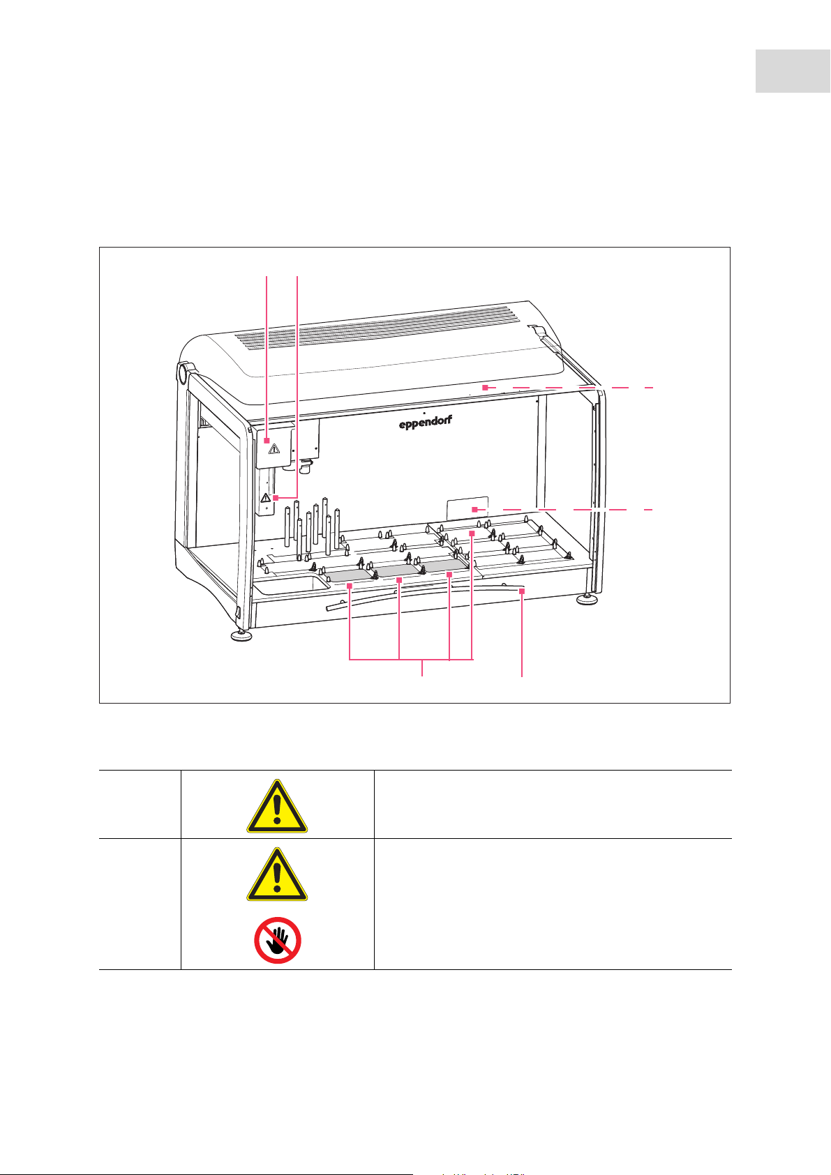
3.5 Hazard symbols and safety devices on the device
This section explains the warning symbols on the epMotion and the location of the safety devices.
Abb. 3-1: Hazard symbols on the epMotion 5075
Safety
®
5075
29
Fig. 3-1: Hazard symbols on the epMotion 5075
Tab. 3-1: Hazard symbols
1 WARNING
Observe the operating manual.
2 WARNING
The carrier may continue moving after the front panel has
been opened.
Wait until the carrier stops moving before reaching into
the device.
Page 30
30
Safety
®
epMotion
5075
English (EN)
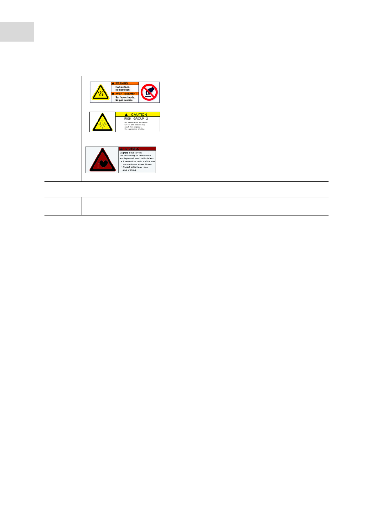
3DANGER
Risk of burns from the hot surface.
Wait until the surface has cooled before touching it.
5NOTICE
Danger due to UV radiation.
Wear personal protective equipment.
6 The label is located on the magnetic finger module and is
only visible to the service technician.
WARN ING
Danger due to strong magnetic field.
Do not work on the device if you wear a pacemaker.
Tab. 3-2: Safety device
4 The housing protects the user from UV radiation, magnetic
fields, contamination and movable parts.
Page 31

Installation
®
epMotion
English (EN)
5075
4 Installation
4.1 Selecting the location
Information on ambient conditions, dimensions and weights can be found in the technical data (see Weight/
dimensions on p. 111).
Select the location for the device according to the following criteria:
Electrical connections
• Mains connection in accordance with the name plate.
• The device mains/power switch and cutting unit of the power system circuit (e.g., FI protective switch)
can be accessed during operation.
Location
• The ambient conditions match the specifications in the technical data.
• The location is well ventilated.
• The location is protected from direct sunlight.
• The location is not next to heat sources, such as heaters or drier compartments.
• There is an adequate amount of space available for the device. The minimum distances to other devices
and walls is 6 cm.
• The device can be safely and easily operated at this location.
31
Workplace
• The lab bench is permanently mounted.
• The lab bench is designed for the weight of the device.
• The lab bench has a horizontal, plane work surface.
• The lab bench has a non-slip surface.
• The lab bench is vibration-free.
• There are no vibrating devices on the lab bench.
4.2 Installing the device
The epMotion may only be installed and commissioned by skilled personnel authorized by
Eppendorf.
Information on transport (see Transport on p. 109).
Page 32

32
Installation
epMotion
®
English (EN)
5075
Page 33

5Hardware
TM 1
TM 2
TM 3
Waste
A2
T0 T1
T4
T2
T3
A3 A4 A5
B3 B4 B5B2B1B0
C1 C2 C3 C4 C5
TM 1
TM 2
TMX
Waste
A2
T0 T1
T4
T2
T3
A3
A4 A5
B3 B4 B5B2B1B0
C1 C2 C3 C4 C5
5.1 Worktable
5.1.1 Layout of the epMotion 5075I worktable
Abb. 5-1: Worktable for epMotion 5075I
Hardware
epMotion
English (EN)
®
5075
33
Fig. 5-1: Worktable for epMotion 5075I
A2-C5
T0
Locations for labware
C1-C3
Waste
With up to 3 thermal modules as an optional
feature
T1-T4
Locations for dispensing tools
5.1.2 Layout of the epMotion 5075t worktable
Abb. 5-2: Worktable for epMotion 5075t
With a gripper as an optional feature
Location for waste container
Fig. 5-2: Worktable for epMotion 5075t
A2-C5
Locations for labware
C1-C2
With 2 thermal modules as an optional feature
A4
Thermomixer
T1-T4
Locations for dispensing tools
T0
With a gripper as an optional feature
Waste
Location for waste container
Page 34

34
TM 1
TM 2
TM 3
VAC
Waste
A2
T0 T1
T4
T2
T3
A3 A4
B4
B3B2B1B0
C1 C2 C3 C4
TM 1
TM 2
TMX
Waste
A2
T0 T1
T4
T2
T3
A3
A4
B3B2B1B0
C1 C2 C3 C4
VAC
B4
Hardware
®
epMotion
5075
English (EN)
5.1.3 Layout of the epMotion 5075v worktable
Abb. 5-3: Worktable for epMotion 5075v
Fig. 5-3: Worktable for epMotion 5075v
A2-C5
T1-T4
Locations for labware
C1-C3
T0
With 3 thermal modules as an optional feature
B4
Waste
Vacuum unit
5.1.4 Layout of the epMotion 5075vt worktable
Abb. 5-4: Worktable for epMotion 5075vt
Fig. 5-4: Worktable for epMotion 5075vt
Locations for dispensing tools
Location for gripper
Location for waste container
A2-C5
Locations for labware
C1-C2
With up to 2 thermal modules as an optional
feature
A4
Thermomixer
B4
Vacuum unit
T1-T4
Locations for dispensing tools
T0
Location for gripper
Waste
Location for waste container
Page 35

5.1.5 Layout of the epMotion 5075m worktable
TM 1
TM 2
Waste
A2
T0 T1
T4
T2
T3
A3
A4 A5
B3 B4 B5B2B1B0
C1 C2 C3 C4 C5
TMX
MagSep
Abb. 5-5: Worktable for epMotion 5075m
Fig. 5-5: Worktable for epMotion 5075m
Hardware
epMotion
English (EN)
®
5075
35
A2-C5
Locations for labware
C1-C2
With up to 2 thermal modules as an optional
feature
A4
Thermomixer
MagSep
Magnet finger module
T1-T4
Locations for dispensing tools
T0
With a gripper as an optional feature
Waste
Location for waste container
Page 36

36
Detector
Diaphragm
Z
Z
0
Imaging optics
Light source
Semi-transparent
mirror
Diaphragm
Hardware
®
epMotion
5075
English (EN)
5.2 Optical sensor
Abb. 5-6: Optical sensor principle
Fig. 5-6: Optical sensor principle
On the carrier, the optical sensor is located to the right of the tool holder.
The optical sensor records the intensity of the reflected light using a lateral infrared light source,
semi-transparent mirror, fixed lens and the procedure in z-direction. Height z
is defined as the point with
0
the highest intensity which enables the detection of the level in a vessel or the presence of labware.
The optical sensor can detect horizontal, plane surfaces. The surface of the liquid must be at an angle of
90° ± 3° to the optical axis.
The surfaces of liquids can be strongly bent by the vessel geometry or the physical properties of the liquid
or vessel. The optical sensor may not detect the level on strongly bent surfaces. If this is the case, the user
must enter the liquid volume.
The optical sensor has a detection limit for vessel levels. The detection limit depends on the vessel
geometry. Generally, levels of 3 mm or higher can be detected.
The following functions of the optical sensor can be activated:
• Liquid detection
Determines the filling level for positions of labware, which has the Liquid detection option activated.
• Tip detection
Checks to see if the pipette tips defined in the application are available.
Determines the quantity and position of tips in the rack.
Works only with epT.I.P.S. Motion in TipHolders and Racks from Eppendorf.
• Location detection
Detects the labware coding.
Checks to see if the labware on the epMotion worktable matches the labware on the epBlue worktable.
Information on setting the optical sensor, and a detailed description of all functions, can be
found in the software operating manual.
Page 37

5.3 Thermal module
Based on the model, your epMotion can be equipped with one or more thermal modules.
5.3.1 Safety notes
WARNING! Danger due to flammable or explosive liquids.
Do not use explosive substances.
Do not heat any highly flammable substances.
Heat highly flammable substances in small quantities below boiling point only.
Do not exceed the boiling point of solutions.
CAUTION! Burns from hot metal surfaces.
The metal surface heats up during operation. The software displays the current temperature of
the metal surface.
Hardware
epMotion
English (EN)
®
5075
37
Wait until the metal surface has cooled down completely.
CAUTION! Burns from hot labware.
Labware will be tempered during operation.
Do not touch temperature-controlled labware.
Wait until the labware has cooled down completely.
NOTICE! Material damage due to non-heat-resistant labware.
Samples and labware will become damaged if you do not use heat-resistant labware.
Observe the labware specifications.
At set temperatures in excess of 100 °C, only use labware made of metal, polypropylene
(PP) or polycarbonate (PC).
5.3.2 Configuration
Abb. 5-7: Thermal module
Fig. 5-7: Thermal module
Thermal modules temper liquids in a temperature range of 0 °C – 110 °C.
Page 38

38
Hardware
®
epMotion
5075
English (EN)
Tab. 5-1: Temperature control duration for labware with thermal module
Labware on the
thermal module
Water filling
volume per well
Cooling from
25°C to 4°C
Heating from
25°C to 37°C
in µL
Temperature
setting in °C
Thermal module
min Temperature
setting in °C
528
without labware
Thermoadapter with
50 3 7 38 5 104 11
96-well twin.tec
PCR plate skirted
Thermoblock with 96-well
50 3 6 37 4 101 10
twin.tec PCR plate skirted
Thermoadapter with
10 3 5 37 5 103 8
384-well twin.tec
PCR plate skirted
Thermoblock with
10 3 5 37 5 98 7
384-well twin.tec
PCR plate skirted
24-unit thermorack with
350 3 24 37 16 101 35
0.5 mL Safe-Lock tubes
24-unit thermorack with
1200 3 30 38 18 104 44
1.5 mL Safe-Lock tubes
24-unit thermorack with
1700 3 25 37 17 100 40
2.0 mL Safe-Lock tubes
Heating from
25°C to 95°C
min Temperature
setting in °C
min
This information applies at an ambient temperature of 25 °C for the border positions in the labware. The
thermal modules were tempered at the target temperature before the labware was positioned.
Information on setting the thermal module and a detailed description of all functions can be
found in the "Operation" chapter of the software instructions.
5.3.3 Equipping the thermal module
When you use a thermoblock or thermoadapter, plates with uneven bases will be optimally tempered, e.g.,
PCR plates.
Equip the thermal module as follows:
1. Place the plate on the thermoadapter or thermoblock.
2. Place the plate, with thermoadapter or thermoblock, on the thermal module.
Page 39

5.4 Thermomixer
Based on the model, your epMotion can be equipped with a thermomixer.
5.4.1 Safety notes
WARNING! Danger due to flammable or explosive liquids.
Do not use explosive substances.
Do not heat any highly flammable substances.
Heat highly flammable substances in small quantities below boiling point only.
Do not exceed the boiling point of solutions.
CAUTION! Burns from hot metal surfaces.
The metal surface heats up during operation. The software displays the current temperature of
the metal surface.
Hardware
epMotion
English (EN)
®
5075
39
Wait until the metal surface has cooled down completely.
CAUTION! Burns from hot labware.
Labware will be tempered during operation.
Do not touch temperature-controlled labware.
Wait until the labware has cooled down completely.
NOTICE! Contamination of samples and the device due to high mixing frequency.
If the speed is set too high, liquid will spray out of the vessels. Labware may become loose
from the holder and fly around.
Observe the maximum speeds of the labware in the operating instructions.
5.4.2 Configuration
Abb. 5-8: Thermomixer
Fig. 5-8: Thermomixer
The thermomixer tempers and mixes liquids and suspensions.
Page 40

40
Hardware
®
epMotion
5075
English (EN)
The thermomixer works in a temperature range of 4 °C – 95 °C. The lowest temperature the thermomixer
reaches is 15 °C below ambient temperature. If the ambient temperature is 20 °C, the thermomixer reaches
at least 5 °C.
Tab. 5-2: Maximum speed for labware on the thermomixer
Labware Maximum speed in rpm
Tubes 1000
DWP 96 1200
DWP 384 1200
MTP 6 1000
MTP 96 2000
MTP 384 2000
PCR 96 2000
PCR 384 2000
Reservoir Rack Cannot be mixed
Thermorack/Thermoblock 1000
Thermoadapter 96 1000
Thermoadapter 384 1000
Thermorack TMX 1300
PrepRack 1300
Information on setting the thermomixer, and a detailed description of all functions, can be
found in the software instructions.
5.4.3 Equipping the thermomixer
When you use a thermoblock or thermoadapter, plates with uneven bases will be optimally tempered, e.g.,
PCR plates.
Equip the thermomixer as follows:
1. Place the plate on the thermoadapter or thermoblock.
2. Place the plate, with thermoadapter or thermoblock, on the thermomixer.
The plate will be fastened to the thermomixer during the application.
Page 41

5.5 Magnet finger module
Based on the model, your epMotion can be equipped with a magnet finger module.
5.5.1 Configuration
Abb. 5-9: Magnet finger module
Hardware
epMotion
English (EN)
®
5075
41
Fig. 5-9: Magnet finger module
The magnet finger module is located behind the thermomixer.
The magnet finger module is used to separate suspended magnetic particles.
The magnet finger module has 3 fingers that can be moved horizontally. Strong permanent magnets are
located on each finger. The 3 magnet fingers move toward the vessels via the lateral openings in the
PrepRack. The magnetic field separates the magnetic particles on the tube inner wall. The dispensing tool
can remove liquid from the vessels, or dispenses liquid in the vessels, while the magnetic particles are held
in place.
The PrepRack is required to perform a separation (see p. 74).
The separation period can be defined using the epMotion software.
For a full nucleic acid purification, you can use the MagSep kits supplied by Eppendorf AG.
5.5.2 Equipping the magnet finger module
The geometry of the used vessels is important for the quality of the separation. Use 2.0 mL
Safe-Lock tubes.
Equip the magnet finger module as follows:
1. Equip the PrepRack with vessels.
2. Place the equipped PrepRack on the thermomixer.
The PrepRack will be fastened on the thermomixer when the application is started.
Page 42

42
Hardware
®
epMotion
5075
English (EN)
5.6 Vacuum unit
Abb. 5-10: Vacuum unit with vacuum frame
Fig. 5-10: Vacuum unit with vacuum frame
The vacuum unit uses a vacuum to suck liquid from a filter plate into a collection vessel. The vacuum is set
via the software and generated by a vacuum pump. The vacuum unit consists of a vacuum chamber,
vacuum pump and vacuum frame and a lid.
You can use the following labware as collection vessels:
•Micro test plate (MTP)
• Deepwell plate (DWP)
•Tube plate
• 400 mL reservoir
• 300 mL reservoir
The gripper places filter plates, VAC Lid and Vac Thermo Lid on the vacuum frame. The gripper transports
the vacuum frame with the attached filter plate.
5.6.1 Vac Frame vacuum frame
Abb. 5-11: VAC Frame 1
Fig. 5-11: VAC Frame 1
The vacuum frame is placed on the vacuum unit. The filter plate is positioned on the vacuum frame.
The frame of the plate must sit on top of the VAC Frame rubber. Otherwise, a vacuum cannot be created.
The Vac Frame is available in 2 different heights for this.
The vacuum frame is positioned on the vacuum unit or on the vacuum holder. The vacuum frame cannot be
positioned directly on the worktable.
The vacuum frame is transported with the gripper.
Page 43

5.6.2 VAC Lid
1
2
3
Abb. 5-12: VAC Lid
Fig. 5-12: VAC Lid
Hardware
epMotion
English (EN)
®
5075
43
1VAC Lid
3Pins
2Silicone mat
Use the VAC Lid if do not want to apply the vacuum to the entire plate. Place the VAC Lid on the vacuum
unit and cover any bores that are not required with the silicone mat. The VAC Lid contains 96 bores. The
bores correspond to the positions of the wells on the filter plate.
The VAC Lid is positioned on the vacuum unit or on the gripper holder.
The VAC Lid is transported with the gripper.
5.6.3 Silicone mat for VAC Lid
Abb. 5-13: Bores in the VAC Lid covered with silicone mat
Fig. 5-13: Bores in the VAC Lid covered with silicone mat
If you are not using some of the filter plate wells you can cover the corresponding bores in the VAC Lid with
a silicone mat. The air does not flow through the covered bores. The vacuum only affects the wells that are
in use.
Silicone mats are available in different sizes. You can cover 16, 32, 48, 64 or 80 bores with the silicone mat.
The silicone mat has the number of bores it covers punched into it.
To attach a silicone mat on the VAC Lid, place the silicone mat on the pins of the VAC Lid.
Page 44

44
Hardware
®
epMotion
5075
English (EN)
5.6.4 Vac Thermo Lid
Abb. 5-14: VAC Thermo Lid
Fig. 5-14: VAC Thermo Lid
The Vac Thermo Lid has a block with a high heat capacity. The Vac Thermo Lid is heated on a thermal
module. On the vacuum unit, air is sucked in through the slits in the Vac Thermo Lid. The air heats up on
the block and flows through the filter plates.
With the Vac Thermo Lid, you can optimize automated nucleic acid preparation. You can minimize the
alcohol in filter plates, the risk of contamination from alcohol is reduced.
The Vac Thermo Lid can be placed on a thermal module and on the vacuum unit.
The gripper transports the Vac Thermo Lid.
The Vac Thermo Lid cannot be placed on the thermomixer.
5.6.4.1 Using the Vac Thermo Lid
CAUTION! Burns from the hot base of the Vac Thermo Lid.
When you temper the Vac Thermo Lid, its base becomes hot.
Wait until the base of the Vac Thermo Lid has cooled down completely.
1. Place the Vac Thermo Lid on a thermal module.
Do not place a reservoir rack with reservoirs in the transport route of the Vac Thermo Lid.
Reservoir racks with reservoirs collide with the VAC Thermo Lid on the gripper.
2. Heat the Vac Thermo Lid to the required temperature before starting the application.
Heating the Vac Thermo Lid to 110 °C takes approx. 30 min.
Page 45

Hardware
®
epMotion
5075
English (EN)
5.6.5 Elution plate adapter
Abb. 5-15: Elution plate adapter
Fig. 5-15: Elution plate adapter
If you are using tube plates as collection vessels you need to use the elution plate adapter. The elution plate
adapter ensures that the tube plates sit firmly in one position.
45
The eluation adapter is made from stainless steel.
5.6.5.1 Using the elution plate adapter
1. Place the elution plate adapter on the edge of the tube plate.
Page 46

46
1
2
3
4
5
Hardware
®
epMotion
5075
English (EN)
5.6.6 Loading the vacuum unit
1VAC Lid
2Filter plate
4 Collection vessel
5 Vacuum unit
3 Vacuum frame
Load the vacuum unit as follows:
1. Place the collection vessel on the vacuum unit.
2. If applicable, place channeling plate 96 on the collection vessel.
3. Place the vacuum frame on the collection vessel.
The weight of the vacuum frame presses the collection vessel into the vacuum unit.
If the vacuum frame is incorrectly positioned, the vacuum will not be generated.
4. Place the filter plate in the vacuum frame.
5. If applicable, place the VAC Lid or the VAC Thermo Lid on the filter plate.
The label on the VAC Lid and the Vac Thermo Lid must face the front
6. The VAC Lid and Vac Thermo Lid can be transported during the application. For the transport, place the
VAC Lid on the gripper holder and the VAC Thermo Lid on a thermal module.
Page 47

Hardware
epMotion
®
English (EN)
5.7 CleanCap
The CleanCap is optional equipment for the epMotion and can only be ordered with a new device. The
CleanCap includes a HEPA filter and a UV lamp.
5.7.1 HEPA filter
WARNING! Risk of infection due to aerosols.
If you work with the HEPA filter, a continuous air flow will be blown from the epMotion
workspace to the ambience. The air flow can transport aerosols and contaminate the
ambience.
Do not use the HEPA filter when working with biohazardous substances.
Disinfect contaminated surfaces in the epMotion workspace before switching on the HEPA
filter.
5075
47
The HEPA filter will become dirty over time. Have the HEPA filter replaced by Eppendorf
Service once per year.
The HEPA filter cleans the air in the epMotion workspace. The HEPA filter reduces the amount of particles
such as dust or germs.
The fan continuously draws air out of the ambience and channels it to the HEPA filter. The filtered air flow
will be routed to the epMotion workspace.
5.7.1.1 Using HEPA filters
Use the HEPA filter as follows:
Prerequisites
• The epMotion is ready for operation.
1. Decontaminate the surfaces in the epMotion workspace.
2. Decontaminate labware and dispensing tools.
3. Close the front hood.
4. Switch on the HEPA filter using the software. (refer to the epMotion software operating manual).
5. Let the HEPA filter run for 5 min.
All of the air in the epMotion workspace has been filtered.
6. Equip the epMotion.
7. Close the front hood.
8. Start the application.
The HEPA filter remains switched on after the end of the application.
9. Start another application, or switch off the HEPA filter using the operating software.
Page 48

48
Hardware
epMotion
English (EN)
®
5075
5.7.2 UV lamp
CAUTION! Risk to health due to UV radiation.
UV radiation causes eye and skin damage.
UV radiation may escape outward through the ventilation slits in the rear panel of the
epMotion.
Wear your personal protective equipment when you are near the ventilation slits.
NOTICE! Damage to plastic due to UV radiation.
Plastics become brittle due to exposure to UV radiation.
Remove the dispensing tools, labware and waste container from the worktable before
switching on the UV lamp.
The radiated power of the UV lamp decreases with age. Have the UV lamp replaced by
Eppendorf Service once every 2 years.
The UV lamp decontaminates the worktable. An irradiation cycle lasts 15 min. The UV lamp is controlled by
the software.
5.7.2.1 Using UV lamps
Prerequisites
• The epMotion is ready for operation.
1. Remove the labware, waste container and dispensing tools from the worktable.
2. Close the front hood.
3. Switch on the UV lamp using the software (refer to the epMotion software operating manual).
When you open the front hood, the UV-lamp switches off.
Information on decontaminating labware and dispensing tools is available (see
Decontamination and cleaning on p. 97)
Page 49

5.8 Barcode reader
1
2
Abb. 5-16: Model of a barcode reader
Hardware
epMotion
English (EN)
®
5075
49
Fig. 5-16: Model of a barcode reader
1Window 2Key
With the barcode reader you can track and document your samples via barcode IDs.
The barcode reader is connected to a USB port on the MultiCon.
Plates have a barcode ID. The barcode ID of a well is generated automatically from the barcode ID of the
plate and the identification of the well. Racks do not have a barcode ID. Each tube in a rack has a barcode
ID.
The barcode reader has 2 settings:
• Manual: To read a barcode ID, press a key on the barcode reader.
• Automatic: To read a barcode ID, hold the barcode reader to the barcode. The barcode reader detects
the barcode IDs automatically.
Page 50

50
50
Hardware
®
epMotion
5075
English (EN)
5.9 Tools
NOTICE! Damage to the gold contacts from handling.
The tool is damaged if the gold contacts on the tool become damaged or contaminated.
Do not touch the gold contacts.
The tool holder picks up a dispensing tool and puts it down again. The tool holder recognizes the tool from
its gold contacts.
The tool holder also picks up the gripper.
5.9.1 Dispensing Tools
Abb. 5-17: Single-channel dispensing tool and eight-channel dispensing tool
50
Fig. 5-17: Single-channel dispensing tool and eight-channel dispensing tool
The dispensing tools are piston-stroke pipettes. The function of the dispensing tools is described in the
chapter (see Dispensing liquids on p. 53).
Single-channel dispensing tools and eight-channel dispensing tools, with 3 volume ranges each, are
available for the epMotion.
Tab. 5-3: Volume range of the dispensing tools
Single-channel dispensing tool Multi-channel dispensing tool Volume range
TS 50 TM 50 1 µL – 50 µL
TS 300 TM 300 20 µL – 300 µL
TS 10000 TM 1000 40 µL – 1000 µL
The dispensing tool errors can be found in the technical data (see p. 115).
Help on dispensing errors can be found in the "Maintenance" chapter (see Dispensing errors on p. 107)
Page 51

5.9.2 Gripper
CAUTION! Risk of injury from mandrels on the gripper arms.
Each gripper arm has 2 sharp mandrels on the inside.
Handle the gripper from above.
Do not touch the gripper arms on the inside.
Abb. 5-18: Gripper with gripper holder
Hardware
epMotion
English (EN)
®
5075
51
Fig. 5-18: Gripper with gripper holder
The gripper transports labware. The gripper uses the mandrel and peg to hold the labware on the gripper
arms. The gripper is placed on the gripper holder.
The gripper transports the following labware: The gripper does not transport the following
labware:
•Plate
All plates will be transported. Plates will be
placed on a worktable, stack, height adapter or
thermoadapter.
•Thermoblock
Will be transported with the positioned plate.
The positioned plate will not be picked up by the
gripper without the thermoblock.
•Thermorack
Will be transported with the inserted reaction
vessels. The inserted reaction vessels will not be
picked up by the gripper without the
thermorack.
• Individual vessels
•Plate stack
The top plate will be transported from a plate
stack.
• epT.I.P.S. Motion Racks
• Racks
• Reservoir Racks
• Reservoirs and Reservoir Rack modules
• Height adapter
• Thermoadapter
A plate will be transported if it is inserted in a
thermoadapter.
•ReagentRack
•PrepRack
Will be transported with the inserted reaction
vessels. The inserted reaction vessels will not be
picked up by the gripper without the
thermorack.
• 300 mL reservoir
• 400 mL reservoir
• Vacuum frame
Is transported on its own or with the filter plate
attached.
• VAC Lid and Vac Thermo Lid
Page 52

52
Hardware
epMotion
®
English (EN)
5075
Page 53

6 Dispensing liquids
upper end position
basic position
end of blow-out
AB C
6.1 Basic procedure for dispensing
6.1.1 Operating principle of dispensing tools
Abb. 6-1: Piston-stroke pipette principle
Fig. 6-1: Piston-stroke pipette principle
Dispensing liquids
®
epMotion
5075
English (EN)
53
AAspirate
The piston moves upward from the home position
and aspirates liquid.
BDispense
Liquid dispensing.
CBlow-out
Dispenses the residual liquid
Blow-out in the Pipette dispensing mode
Remaining stroke in the Multidispense dispensing
mode
Multidispense: Piston travels to the home position
in separate steps.
Pipette: Piston travels to the home position in one
step.
The dispensing tools are piston-stroke pipettes that function according to the air cushion principle.
If the piston moves upward in the dispensing tool, liquid will be aspirated into the pipette tip. If the piston
moves downward in the dispensing tool, liquid will be dispensed from the pipette tip. The pistons will be
moved by a motor in the tool holder.
On eight-channel dispensing tools, all 8 channels move simultaneously.
Page 54

54
1 mm
0,7 mm
Dispensing liquids
®
epMotion
5075
English (EN)
6.1.2 Liquid aspiration up to the remaining volume
Abb. 6-2: Liquid aspiration up to the remaining volume with a constant immersion depth
Fig. 6-2: Liquid aspiration up to the remaining volume with a constant immersion depth
The pipette tip is immersed 3 mm into the liquid before liquid aspiration. The pipette tip moves downward
during liquid aspiration. The immersion depth of 3 mm remains constant while the liquid level decreases.
If the pipette tip reaches a distance of 1 mm to the base of the vessel, the pipette tip reduces its immersion
depth to 0.7 mm. If the liquid level continues to sink, the pipette tip will not aspirate any additional liquid.
The remaining volume remains in the vessel.
A remaining volume is present because the pipette tip has a minimum immersion depth in the liquid and a
minimum distance to the base of the vessel. Under normal conditions, the remaining volume is calculated
using a filling level of 1.7 mm.
The distance of the pipette tip to the base of the vessel can be changed in the software (refer to the
epMotion software operating manual).
If the liquid is aspirated from the remaining volume, the bend of the liquid level can lead to
dispensing errors.
6.1.3 Bottom tolerance
The bottom tolerance is the distance between the vessel base and the lower end of the pipette tip. The
default setting for the bottom tolerance is 1 mm. For 30 mL and 100 mL reservoirs, the default setting for
the bottom tolerance is 2.5 mm.
Decreasing the bottom tolerance also reduces the remaining volume.
1. Removing liquid above a pellet increases the bottom tolerance.
2. Do not decrease the bottom tolerance on uneven plates.
3. Check the set bottom tolerance when exchanging pipette tips, plates or vessels.
Page 55

6.1.4 Transporting and dispensing liquid
~ 3 - 4 mm
~ 6 - 8 mm
AB
Abb. 6-3: Transporting and dispensing liquid
Fig. 6-3: Transporting and dispensing liquid
Dispensing liquids
®
epMotion
5075
English (EN)
55
A Dispensing liquid B Retraction of liquid after liquid aspiration
6.1.4.1 Dispensing liquid
The liquid from the pipette tip will be dispensed in the free jet. The liquid will be dispensed into the vessel
3 mm – 4 mm above the surface of the liquid. The pipette tip moves upward during dispensing. The
distance from the pipette tip to the surface of the liquid remains constant.
For liquid type ProteinC, a distance of 5 mm from the pipette tip to the surface of the liquid is set in the
software. This setting takes into account the tendency of concentrated protein solutions to form foam.
6.1.4.2 Transporting liquids
The liquid is drawn into the pipette tip before transport. An area filled with air is created in the lower part of
the pipette tip. The liquid does not drip during transport.
Page 56

56
Dispensing liquids
epMotion
English (EN)
®
5075
6.2 Dispensing modes
The epMotion can be used to dispense liquids in the Pipette and Multidispense modes.
6.2.1 Dispensing mode: Pipette
In the Pipette mode, a defined volume of liquid is aspirated and fully dispensed.
Dispensing errors are smaller than in the Multidispense (see Dispensing tool errors on p. 115) mode.
The epMotion executes a blow-out in the Pipette mode. Residual liquid from the pipette tip will be
dispensed in the destination vessel. The blow-out is part of the dispensing volume. The blow-out can be set
in the software (refer to the epMotion software operating manual).
In the Pipette mode, the smallest dispensing volume for water is 1 L.
6.2.2 Dispensing mode: Multidispense
In the Multidispense mode, liquid is aspirated and dispensed in the destination vessels in defined partial
quantities.
Dispensing errors are larger than in the Pipette (see Dispensing tool errors on p. 115) mode.
The epMotion carries out a remaining stroke in the Multidispense mode. Residual liquid from the pipette tip
will be dispensed in the waste vessel or source vessel. The residual liquid is not part of the dispensing
volume.
In the Multidispense mode, the smallest dispensing volume for water is 3 L.
6.2.2.1 Aspiration volume at Multidispense
To create the same physical conditions for all dispensing steps, more liquid must be aspirated in the
Multidispense mode than the sum of the dispensing volumes. This is the result of the reverse stroke and the
remaining stroke.
Reverse stroke
• The reverse stroke occurs after liquid aspiration.
Part of the aspirated volume is immediately returned to the source vessel.
The reverse stroke is the same size for all liquids.
Remaining stroke
• After the reverse stroke, there is more liquid in the pipette tip than the amount required for the
dispensing steps. This additional aspiration volume will be dispensed as a remaining stroke after
dispensing.
The additional aspiration volume will be dispensed to the source vessel if the tips are not replaced
before each liquid aspiration.
The additional aspiration volume will be dispensed to the waste container if the tips are not replaced
before each liquid aspiration.
Page 57

Dispensing liquids
epMotion
English (EN)
The volume for the additional aspriation depends on the dispensing tool; the software will take it into
account when calculating the required aspiration volume.
®
5075
57
Dispensing tool Additional volume per
channel for reverse stroke
Single-channel dispensing tool TS 50
Eight-channel dispensing tool TM 50
Single-channel dispensing tool TS 300 16.7 µL 3.7 µL
Eight-channel dispensing tool TM 300 45.2 µL 5.0 µL
Single-channel dispensing tool TS 1000
Eight-channel dispensing tool TM 1000
Example for aspiration volume for multi-dispensing
A 96-well plate should be filled with 10 L water in each well via multi-dispensing. The eight-channel
dispensing tool TM 50 is used. Aspiration is performed from one reservoir. The tips are not changed before
a new liquid aspiration.
Sum of the aspiration volumes for multi-dispensing:
• 96 x 10 L for 96-well plate: 960 L
• 8 x 5.8 L reverse stroke: 46.4 L
• 8 x 2.5 L additional aspiration: 20 L
•Sum: 1026.4 L
5.8 µL 2.5 µL
50.3 µL 35.2 µL
Additional volume per
channel for remaining stroke
6.2.3 Mixing
Liquids can be mixed via multiple pipetting.
A mixing cycle consists of one upward movement and one downward movement of the piston in the
dispensing tool.
The aspiration level and dispensing level of the liquid can be defined during mixing. A defined height
should only be used for levels below the working volume as the vessel may overflow with larger levels.
During the mixing process, the pipette tip is in the liquid. The blow-out will be executed above the surface
of the liquid after the mixing procedure.
Defined mixing speeds are defined in the liquid types. When using your own settings, determine the
optimal mixing speed via experiments.
NOTICE! Contamination of the dispensing tool due to high mixing frequency.
If the mixing frequency is too high, liquid may enter the dispensing tool.
If the liquid has a low viscosity or tends to foam, set a low mixing frequency.
Use demineralized water to test the mixing settings.
Use pipette tips with filter.
Page 58

58
AB
Dispensing liquids
®
epMotion
5075
English (EN)
6.2.3.1 Recommended mixing speeds
You can set mixing speeds of 0.2 mm/s – 110 mm/s.
Dispensing tool Mixing speed of lower
volume range in mm/s
Mixing speed of
medium volume range
Mixing speed of upper
volume range in mm/s
in mm/s
TS 50 15 – 88 15 – 44 10 – 40
TM 50 15 – 88 15 – 44 10 – 40
TS 300 5 – 15 6 – 16 6 – 16
TM 300 2 – 11 2 – 11 2 – 11
TS 1000 4 – 15 4 – 15 4 – 15
TM 1000 4 – 15 4 – 15 4 – 15
6.3 Special features
6.3.1 Liquid aspiration from bottom of vessel
The pipette tip can also be positioned above the bottom of the vessel at the height of the bottom tolerance.
This prevents the pipette tip from changing its position during liquid aspiration.
The level in the vessels may not exceed the working volume. If the level exceeds the working volume, liquid
may overflow.
Liquid aspiration from the bottom of the vessel is recommended in the following cases:
• For vessels ≤0.5 mL, 96-well plates and 384-well plates
• For plates with various filling volumes in the wells
•For vessels with low filling volumes
Liquid aspiration from the bottom of the vessel can be activated in the software using the Aspirate from
bottom option (refer to the epMotion software operating manual). The bottom tolerance, which can be set in
the software, depends on the labware.
Abb. 6-4: Liquid displacement in vessels
Fig. 6-4: Liquid displacement in vessels
A Vessel filled up to the working volume B Vessel with maximum immersed tip before
liquid aspiration
Page 59

Dispensing liquids
epMotion
6.3.2 Liquid aspiration from high vessels
Observe the following special features when using high vessels, e.g., 15 mL centrifuge tubes.
6.3.2.1 Liquid aspiration from bottom of vessel
Abb. 6-5: Large vessel with high liquid level
Fig. 6-5: Large vessel with high liquid level
®
5075
English (EN)
59
If you use vessels > 3 mL with high levels, do not aspirate liquids from the bottom of the vessel. This will
result in the outside of the pipette tip being wetted, which increases the risk of contamination and distorts
the dispensing result. For very large vessels with high levels, the entire pipette tip and the tip cone of the
dispensing tool will be wetted.
6.3.2.2 High remaining volume
Abb. 6-6: Liquid aspiration from high vessels with 1000 µL, 50 µL and 300 µL pipette t ips
Fig. 6-6: Liquid aspiration from high vessels with 1000 µL, 50 µL and 300 µL pipette tips
50 L tips and 300 L tips do not extend as far into the vessels as 1000 L tips. In high vessels, 50 L and
300 L tips do not reach the bottom of the vessels. If you use 50 L and 300 L tips, the remaining volume
will be larger than with 1000 L tips.
Work with the 1000 µL dispensing tool when you use high vessels.
If you use the 50 µL dispensing tool or the 300 µL dispensing tool, and would like to reduce
the remaining volume, select the lower vessels.
Page 60

60
Dispensing liquids
epMotion
English (EN)
®
5075
6.3.3 Liquid dispensing at the height of the vessel edge
In the software, the pipette tip can be positioned at a height of 3 mm – 4 mm below the edge of the vessel
using the Dispense from top option. The height of the pipette tip does not change.
Use the option for:
•Quick dispensing
• Dispensing in vessels with small diameters, e.g., 384-well plates, capillaries
The tips remains in the upper area of the vessel and do not travel further into the vessel. This virtually
eliminates the possibility of the pipette tip becoming contaminated.
• Dispensing in plates with vastly different levels in the wells
6.3.4 Liquid aspiration from a filter plate
In the software, liquid can be suctioned from the supernatant of filter plates and filter vessels via the Elution
from filter option.
The Elution from filter option refers to the source vessel and almost fully aspirates liquid from the filter
plate. The pipette tip touches the filter. The piston movement in the dispensing tool for liquid aspiration
starts when the pipette tip moves in the vessel. Maximum stroke is used on each dispensing tool. This also
applies to dispensing.
When the liquid is being transported, air bubbles may be present at several locations in the pipette tip. The
size of the air bubble on the lower end of the pipette tip may vary.
Page 61

Labware – vessels, plates and pipette tips
®
epMotion
5075
English (EN)
7 Labware – vessels, plates and pipette tips
The term labware refers to epMotion consumables and accessories. Consumables are vessels, plates and
pipette tips. Accessories are adapters, blocks and racks. epBlue includes a definition for labware that is
placed on the epMotion worktable. The definition includes data on the geometry, tempering ability, volume
and bottom tolerance of the labware.
The epMotion can be used with a variety of labware from various manufacturers. Information
on how to expand the labware library can be found in the software operating manual.
Labware may not exceed an overall height of 126 mm. The software generates an error
Abb. 7-1: Reaction vessel with lid
message if this overall height is exceeded.
61
1.5
1.0
0.5
0.1
1
2
3
4
Fig. 7-1: Reaction vessel with lid
1 Filling volume
2 Working volume
3 Detection limit of optical sensor
4 Remaining volume
7.1 Tubes
The vessels will be inserted in racks. All reaction vessels which fit in an epMotion rack can be used.
Examples of reaction vessels that can be used:
•Safe-Lock tubes
• Standard reaction vessels 3810X
• PCR vessels
• Conical tubes/centrifuge tubes
•Cryotubes
Individual reaction vessels are not transported with the gripper.
Level measurement using the optical sensor is more difficult with 0.2 mL and 0.5 mL tubes.
Use Thermoracks or Reservoir Rack modules to temper vessels.
Page 62

62
Labware – vessels, plates and pipette tips
®
epMotion
5075
English (EN)
7.2 Plates
Abb. 7-2: Plates: left 96-well MTP, middle 24-well MTP, right 96-well DWP
Fig. 7-2: Plates: left 96-well MTP, middle 24-well MTP, right 96-well DWP
The following plates are available for the epMotion:
• DWP plates with 24, 96 or 384 wells
• MTP plates with 6, 24, 48, 96 or 384 wells
• Filter plates for use with the vacuum unit
• PCR plates with 96 or 384 wells
• Vessel plates with 96 individual vessels (tube plates)
Skirted plates can be placed directly at a worktable location. Plates can be placed on adapters.
Plates are transported with the gripper. Stacked plates will not be transported together.
Stacking plates
If they are manufactured by Eppendorf, the same type of plates can be stacked on the worktable. If you
would like to stack plates, use Eppendorf plates. Plates from other manufacturers may have deviating
dimensions, which will prevent them from being stacked.
7.2.1 Deepwell plates
Abb. 7-3: Deepwell plate with 96 wells
Fig. 7-3: Deepwell plate with 96 wells
A maximum of 2 Eppendorf DWP plates can be stacked at one location.
A thermoadapter is available for the Eppendorf 1.0 mL deepwell plate.
Page 63

Labware – vessels, plates and pipette tips
epMotion
English (EN)
7.2.2 Microplates
Abb. 7-4: Microplate wi th 96 wells
Fig. 7-4: Microplate with 96 wells
A maximum of 5 Eppendorf MTP plates can be stacked at one location.
A level measurement with optical sensor cannot be completed for an MTP with 384 wells. A level
measurement with optical sensor is not recommended for an MTP with 96 wells.
7.2.3 Filter plates
Abb. 7-5: Filter plate with 96 wells
®
5075
63
Fig. 7-5: Filter plate with 96 wells
Filter plates are available for nucleic acid purification with a vacuum unit.
Each well of a filter plate includes a filter and an opening at the bottom.
7.2.4 Channeling plate 96
Abb. 7-6: Channeling plate 96
Fig. 7-6: Channeling plate 96
The channeling plate 96 is used in the vacuum unit. The Channeling plate 96 protects the filter plate against
contamination.
The channeling plate 96 is positioned on the collection vessel in the vacuum unit. If you insert the
Channeling Platte 96 you can only use the 400 mL reservoir as the collection vessel.
Due to the geometry of the filter plates, the Channeling Plate 96 is recommended for Qiagen applications
(QIAamp 96 DNA Blood and QIA_Rneasy 96).
Page 64

64
Labware – vessels, plates and pipette tips
®
epMotion
5075
English (EN)
7.2.5 PCR plates
Abb. 7-7: PCR plate with 96 wells
Fig. 7-7: PCR plate with 96 wells
PCR plates are available with 96 and 384 wells.
96-well PCR plates are available with a border (skirted), a semi-border (semi-skirted) or without a border
(unskirted).
96-well PCR plates with a semi-border or without a border can only be positioned and transported with the
Thermoblock PCR 96.
Tab. 7-1: Placing PCR plates on the worktable
Plate With thermoblock With thermoadapter Direct
96-well PCR plates skirted x x x
96-well PCR plates semi-skirted x
96-well PCR plates unskirted x
7.2.6 Tube plates
Tube plates are plates with individual vessels. Tube plates are available in various vessel layouts. Tube
plates are treated as normal plates.
Page 65

7.3 Reservoirs
Labware – vessels, plates and pipette tips
®
epMotion
5075
English (EN)
65
Abb. 7-8: 100 mL and 30 mL reservoirs
Fig. 7-8: 100 mL and 30 mL reservoirs
Abb. 7-9: Reservoir 400 mL
Fig. 7-9: Reservoir 400 mL
Reservoirs make liquid available. Reservoirs are available in 30 mL, 100 mL and 400 mL sizes. Reservoirs
for 30 mL and 100 mL are placed in a Reservoir Rack.
Reservoirs are made of polypropylene (PP).
Properties of 30 mL and 100 mL reservoirs
• 30 mL reservoirs can be used with all tips.
• The 30 mL reservoirs are very tight at the bottom. If the bottom tolerance is reduced, reservoirs for
30 mL can also be lifted using pipette tips.
• Reservoirs for 30 mL and 100 mL have a ribbed base. If the bottom tolerance has been reduced, the
information on the remaining volume is not precise.
• Reservoirs for 30 mL and 100 mL are particularly well-suited for eight-channel dispensing tools.
• The eight-channel dispensing tools TM 50 and TM 300 cannot be immersed all the way to the bottom in
the 100 mL reservoir. A higher remaining volume remains in the reservoir.
Properties of 400 mL reservoirs
• The remaining volume of the 400 mL reservoir is approx. 10 mL.
Page 66

66
Labware – vessels, plates and pipette tips
®
epMotion
5075
English (EN)
7.4 epT.I.P.S. Motion
NOTICE! Dispensing error due to incorrect handling of pipette tips.
Tips become deformed and change size during autoclaving.
Do not autoclave the pipette tips. Use tips with the sterile specification, if required.
Do not stack any racks that contain pipette tips.
Observe the instructions for use for the epT.I.P.S. Motion Racks and epT.I.P.S. Motion Reloads.
Abb. 7-10: epT.I.P.S. Motion 1 000 µL, 50µL, 300 µL
Fig. 7-10: epT.I.P.S. Motion 1 000 µL, 50µL, 300 µL
epT.I.P.S. Motion are special pipette tips for the epMotion.
epT.I.P.S. Motion pipette tips, racks and trays are made from polypropylene (PP). The filter is made of
polyethylene (PE).
Racks and trays are not transported with the gripper.
The optical sensor detects the size of the pipette tips via the rack coding. The optical sensor also detects if
the pipette tips have a filter. However, the optical sensor does not use the coding to detect if the pipette tips
are in racks, SafeRacks or in the Tip Holder.
Page 67

Labware – vessels, plates and pipette tips
7.4.1 epT.I.P.S. Motion Racks
Abb. 7-11: epT.I.P.S. Motion Ra ck
Fig. 7-11: epT.I.P.S. Motion Rack
epT.I.P.S. Motion racks are intended for single use.
epT.I.P.S. Motion racks are specially designed for applications that require sterile work.
epMotion
English (EN)
®
5075
67
Tab. 7-2: epT.I.P.S. Motion racks are available in the following sizes:
Size of the pipette tips Dispensing tool Color of the racks
50 µL TS 50, TM 50 Light gray
300 µL TS 300, TM 300 Yellow
1000 µL TS 1000, TM 1000 Dark blue
Tab. 7-3: epT.I.P.S. Motion racks are available in the following purity grades:
epT.I.P.S. Motion Racks Purity grade
Pipette tips with filter PCR clean
PCR clean and Sterile
Pipette tips without filter Eppendorf Quality
Sterile
Page 68

68
Labware – vessels, plates and pipette tips
®
epMotion
5075
English (EN)
7.4.2 epT.I.P.S. Motion Reloads
Abb. 7-12: epT.I.P.S. Motion Reloads in individual packaging
Fig. 7-12: epT.I.P.S. Motion Reloads in individual
Abb. 7-13: epT.I.P.S. Motion Reloads an d tip holder
Fig. 7-13: epT.I.P.S. Motion Reloads and tip holder
packaging
epT.I.P.S. Motion Reloads are intended for single use.
The pipette tips are in trays. The trays will be placed in reusable tip holders, which reduces waste because
no racks are required.
Tab. 7-4: epT.I.P.S. Motion Reloads are available in the following sizes:
Size of the pipette tips Dispensing tool Tray color
50 µL TS 50, TM 50 Light gray
300 µL TS 300, TM 300 Yellow
1000 µL TS 1000, TM 1000 Dark blue
Tab. 7-5: epT.I.P.S. Motion Reloads are available in the following purity grades:
epT.I.P.S. Motion Reloads Purity grade
Pipette tips with filter PCR clean
Pipette tips without filter Eppendorf Quality
Page 69

Labware – vessels, plates and pipette tips
1
2
3
7.4.3 Tip holder for epT.I.P.S. Motion Reloads
Abb. 7-14: Tip Holder
Fig. 7-14: Tip Holder
The tip holder is an adapter that holds the epT.I.P.S. Motion Reloads.
epMotion
English (EN)
®
5075
69
7.4.3.1 epT.I.P.S. Motion Reloads on the tip holder
Abb. 7-15: Placing the tray on the tip holder
Fig. 7-15: Placing the tray on the tip holder
1Tips
2Tray
1. Open the Reload packaging.
2. Remove the tray with the tips.
3. Place the tray on the tip holder. The notch in the tray must be on the labeled side of the tip holder.
3Tip Holder
Page 70

70
Labware – vessels, plates and pipette tips
®
epMotion
5075
English (EN)
7.4.4 epT.I.P.S. Motion SafeRacks
Abb. 7-16: epT.I.P.S. Motion SafeRack
Fig. 7-16: epT.I.P.S. Motion SafeRack
NOTICE! Contamination due to using incorrect pipette tips.
The optical sensor does not detect if the pipette tips on the worktable are intended for single
use (epT.I.P.S. Motion Rack, epT.I.P.S. Motion Reload) or multiple use (epT.I.P.S. Motion
SafeRack).
If the pipette tips will be used several times, equip the entire worktable with epT.I.P.S.
Motion SafeRacks.
The epT.I.P.S. Motion in SafeRacks are intended for multiple use. If you use the pipette tips in an
application, use epT.I.P.S. Motion SafeRacks, for example, to remove buffers in several washing steps.
epT.I.P.S. Motion SafeRacks have a partition to separate pipette tips. During an application, used pipette tip
are returned to the SafeRack. A partition prevents residual liquid from contaminating adjacent pipette tips.
Contamination of samples due to repeated use is prevented because the software permanently allocates the
pipette tips within a specific application to a source vessel.
In the software, you can set whether pipette tips should be used multiple times (refer to the epMotion
software operating manual).
Use epT.I.P.S. Motion SafeRacks for a maximum of 6 usage cycles. A usage cycle consists of
aspiration, dispensing and ejecting the tip.
Tab. 7-6: epT.I.P.S. Motion SafeRacks are available in the following sizes:
Size of the pipette tips Dispensing tool Rack color
50 µL TS 50, TM 50 Light gray
1000 µL TS 1000, TM 1000 Dark blue
Tab. 7-7: epT.I.P.S. Motion SafeRacks are available in the following purity grades:
epT.I.P.S. Motion SafeRacks Purity grade
Pipette tips with filter PCR clean
Pipette tips without filter Eppendorf Quality
Page 71

8 Labware accessories
Vessels and accessories may not exceed an overall height of 126 mm. If this overall height is
exceeded, the software generates an error message.
8.1 Racks
Racks are holders for mounting the same type of individual vessels.
Racks are not transported with the gripper.
8.1.1 Racks for 24 vessels
Abb. 8-1: Rack for 24 vessels
Labware accessories
®
epMotion
5075
English (EN)
71
Fig. 8-1: Rack for 24 vessels
Various racks are available for vessels 12 mm – 17 mm in diameter. Racks are available in 2 heights. The
bores for the vessels are numbered.
The racks cover the same area as plates. Racks can be positioned at any location.
Racks are coded. The optical sensor uses the code to detect if the rack is correctly positioned.
Page 72

72
Labware accessories
®
epMotion
5075
English (EN)
8.1.2 Rack for 96 vessels
Abb. 8-2: Rack 96
Fig. 8-2: Rack 96
The Rack 96 takes up 2 locations on the worktable. The rack holds 96 tubes without lids, with a volume of
1.5 mL or 2 mL.
8.1.2.1 Equipping Rack 96
The Rack 96 can be equipped with vessels with fastened lids, e.g., Safe-Lock tubes.
If you equip the Rack 96 with Safe-Lock tubes, leave the second row of the rack open.
Ensure that the lids do not cover the openings of adjacent vessels.
8.1.2.2 Placing the Rack 96 on the worktable
1. Place the Rack 96 on the epMotion workable so the opening in the lower panel points toward the user.
2. Place the Rack 96 on the positioning pins of the two locations.
Page 73

Labware accessories
®
epMotion
5075
English (EN)
8.1.3 Rack LC
Abb. 8-3: Rack LC 100 µL
Fig. 8-3: Rack LC 100 µL
The Rack LC can hold 96 LightCycler capillaries with a 20 L filling volume or 96 capillaries with a 100 L
filling volume. The bores for both sizes of capillary are arranged in an alternating pattern.
The Rack LC is labeled on both sides. The label on one side indicates the capillary size of 20 µL. The label
on the other side indicates the capillary size of 100 µL.
73
8.1.3.1 Equipping the Rack LC and positioning it on the worktable
Equip the Rack LC. Only use capillaries of the same size for a single application.
Place the Rack LC on the epMotion worktable.
The label that lists the size of the inserted capillary must point toward the user.
8.1.4 Thermorack and Rack 0.5/1.5/2.0 mL
Abb. 8-4: Thermorack 0.5 mL; 1.5 mL; 2 mL
Fig. 8-4: Thermorack 0.5 mL; 1.5 mL; 2 mL
Thermoracks and the 0.5/1.5/2.0 mL racks have 24 bores for tubes with a volume of 1.5 mL and 2 mL.
Vessels with a volume of 0.5 mL can be inserted with adapter sleeves.
Abb. 8-5: Rack 0.5 mL; 1.5 mL; 2 mL
Fig. 8-5: Rack 0.5 mL; 1.5 mL; 2 mL
Thermoracks and 0.5/1.5/2.0 mL racks have lid holders. The lid holders are on the right, next to the bore for
the vessel. The lid holder vertically clamps the tube lids.
Thermoracks and the 0.5/1.5/2.0 mL racks are transported using the gripper.
Thermoracks are suitable for temperature control and designed for use on thermal modules.
Thermoracks can be cooled in the lab refrigerator.
Page 74

74
Labware accessories
®
epMotion
5075
English (EN)
Thermorack TMX
Thermoracks TMX are designed for use with the thermomixer. The Thermorack TMX is lighter than a
standard thermorack and enables higher speeds during mixing. The Thermorack TMX has a low thermal
capacity, but a fast heat transfer. The Thermorack TMX quickly reaches the target temperature, but cannot
maintain this temperature for a long time after temperature control.
The Thermorack TMX is available with installed adapters for vessels with a volume of 0.5 mL.
Tab. 8-1: Test values for temperature control of thermoracks and thermoadapters
Thermorack/thermoadapter Equipping Filling volume
per vessel
Heating time
from 0 °C – 10 °C
Thermorack 1.5/2.0 mL 1.5 mL Safe-Lock tube 1000 µL ~ 30 min
Thermoadapter PCR 96 96-well twin.tec PCR plate 150 µL ~ 14 min
Thermoadapter PCR 384 384-well twin.tec PCR plate 25 µL ~ 10 min
8.1.5 PrepRack
Abb. 8-6: PrepRack
Fig. 8-6: PrepRack
The PrepRack is specially designed for use with the magnet finger module. You can also use the PrepRack
as the standard rack.
The PrepRack has 24 vessel bores which are numbered by row-by-row. The corresponding lid holder is at
the right of the vessel bore. The lid holder vertically clamps the tube lids.
You can equip the PrepRack in the same way as the thermorack and the 0.5/1.5/2.0 mL rack (see p. 73).
The PrepRack is designed to be used on the thermomixer and can be tempered.
The optical sensor detects the PrepRack using its code.
The PrepRack is transported with the gripper.
Page 75

8.1.6 ReagentRack
Abb. 8-7: ReagentRack
Fig. 8-7: ReagentRack
The ReagentRack holds a tray with reagents from the Eppendorf MagSep kits.
Labware accessories
®
epMotion
5075
English (EN)
75
The ReagentRack cannot be placed on the TMX.
The optical sensor detects the tray with reagents using its code.
The ReagentRack is not transported with the gripper.
8.1.6.1 Positioning the ReagentRack on the worktable
The ReagentRack cannot be placed at location B0.
Place the ReagentRack on the worktable so that the Reservoir Rack tabs are positioned between the
locating pins for the location.
Page 76

76
4
1
2
3
Labware accessories
®
epMotion
5075
English (EN)
8.1.7 Reservoir Rack
Abb. 8-8: Equipped Reservoir Rack
Fig. 8-8: Equipped Reservoir Rack
The Reservoir Rack (4) is used to hold reservoirs (1) and Reservoir Rack modules (2). The Reservoir Rack
columns are numbered (3).
The Reservoir Rack can hold a maximum of 7 reservoirs (1) or 7 different Reservoir Rack modules (2).
Reservoir Racks can be loaded in any order.
The ReservoirRack cannot be placed on the thermomixer.
8.1.7.1 Loading Reservoir Racks
The temperature control of the Reservoir Rack modules in the outer positions is not as good.
Insert Reservoir Rack modules and reservoirs in the Reservoir Rack with the code facing the rear.
8.1.7.2 Positioning the Reservoir Rack on the worktable
The Reservoir Rack cannot be placed at A locations or location B0.
Place the Reservoir Rack on the worktable so the Reservoir Rack tabs are positioned between the
positioning pins for the location.
Page 77

Labware accessories
®
epMotion
5075
English (EN)
8.1.8 ReservoirRack 3
Abb. 8-9: ReservoirRack 3
Fig. 8-9: ReservoirRack 3
The ReservoirRack 3 can be used as a waste container for liquid waste.
The ReservoirRack 3 can be equipped with up to 3 reservoirs for 30 mL or 100 mL. The ReservoirRack 3
cannot be equipped with Reservoir Rack modules.
77
8.1.8.1 Positioning the Reservoir Rack 3 on the worktable
You can only position the ReservoirRack 3 in location A5 of the epMotion 5075m and 5075t.
Place the ReservoirRack 3 on the worktable in such a way that the Reservoir Rack tabs are positioned
between the positioning pins for the location.
8.1.9 Reservoir Rack modules
Abb. 8-10: Versions of Reservoir Rack modules
Fig. 8-10: Versions of Reservoir Rack modules
1 Reservoir Rack module TC Ø 29 mm
2 Reservoir Rack module TC Ø 17 mm
3 Reservoir Rack module TC reservoir 100 mL
4 Reservoir Rack module TC reservoir 30 mL
5 Reservoir Rack module TC Ø 16 mm
6 Reservoir Rack module TC Ø 12 mm
7 Reservoir Rack module TC Safe-Lock
8 Reservoir Rack module TC PCR 0.5 mL
9 Reservoir Rack module TC PCR 0.2 mL
10 Reservoir Rack module TC Eppendorf tubes 5 mL
Reservoir Rack modules are equipped with vessels and inserted into a Reservoir Rack. All of the vessels
equipped in a Reservoir Rack module must be of the same type.
The Reservoir Rack modules TC are suitable for temperature control.
Page 78

78
1
2
3
4
2
1
3
Labware accessories
®
epMotion
5075
English (EN)
8.1.9.1 Connecting 30 mL/100 mL TC Reservoir Rack modules to an adjacent module
Abb. 8-11: Connecting the 30 mL/100 mL TC Reservoir Rack module to an adjacent mod ule
Fig. 8-11: Connecting the 30 mL/100 mL TC Reservoir Rack module to an adjacent module
1 Reservoir
2 30 mL/100 mL TC Reservoir Rack modules
3 Connecting web
4 Adjacent module
The 30 mL/100 mL TC Reservoir Rack modules must be mounted to the next Reservoir Rack module using
2 connecting bars.
Insert the 2 connecting bars for the TC Reservoir Rack modules in the next Reservoir Rack modules.
8.1.9.2 Setting the Reservoir Rack module to vessel height
Abb. 8-12: Setting the Reservoir Rack module to vessel height
Fig. 8-12: Setting the Reservoir Rack module to vessel height
1 Positioning screw
3 Reservoir Rack module
In storage position
2 Positioning screw
At 50 mm height setting
The Reservoir Rack modules have bores 12 mm, 16 mm and 17 mm in diameter at the front and rear. The
bores are mounted at 50 mm, 60 mm, 70 mm, 80 mm and 90 mm. Use the 2 positioning screws to position
the vessels at these heights.
Screw the 2 positioning screws into the bores at the required height.
Page 79

Tab. 8-2: Temperature control duration of Reservoir Rack modules and reaction vessels
Temperature change
from 23°C to 4°C
Reservoir Rack module TC Tube Set
temperature
Temperature
control time
Tem pera ture chang e
from 23°C to 37°C
Set
temperature
RR module TC PCR 0.2 mL PCR reaction vessel
0.2 mL
3°C
Approx.
15 min
38 °C
RR module TC PCR 0.5 mL PCR reaction vessel
0.5 mL
Safe-Lock tube
0.5 mL 3°C
RR module TC Safe-Lock
Safe-Lock tube
1.5 mL
Safe-Lock tube
2 °C
3°C
Approx.
20 min
38 °C
2.0 mL
Labware accessories
®
epMotion
5075
English (EN)
Temperature
control time
Approx.
8 min
Approx.
12 min
79
RR module TC Ø 12 mm Reaction vessel
3°C
Ø 12 mm
RR module TC Ø 16 mm Reaction vessel
Ø 16 mm
RR module TC
Tube 5 mL 3°C
3°C
Approx.
30 min
38 °C
Approx.
17 min
Eppendorf tubes 5 mL
RR module TC Ø 17 mm Conical tube 15 mL 2 °C
RR module TC Ø 29 mm Conical tube 50 mL
RR Module TC
Reservoir 30 mL
3°C
1°C
Approx.
39 min
Approx.
21 min
39 °C
39 °C
Approx.
23 min
Approx.
15 min
Reservoir 30 mL
RR Module TC
Reservoir 100 mL
1°C
Approx.
46 min
40 °C
Approx.
28 min
Reservoir 100 mL
The table shows the time it takes to reach the set temperature with specific Reservoir Rack modules and
reaction vessels, if the user has set the set temperature in the software.
Page 80

80
Labware accessories
®
epMotion
5075
English (EN)
8.2 Adapters
The following adapters are available for the epMotion:
• Height adapter
•Thermoadapter
8.2.1 Height adapter
Abb. 8-13: Height adapter
Fig. 8-13: Height adapter
The height adapters are used to offset the various heights of the labware. The tool holder does not need to
offset these height differences and remains at one height. The shorter paths of this tool holder allows the
application to run more quickly.
The height of the adapter is listed on the adapter. The combined height of the labware and the adapter may
not exceed 126 mm.
Height adapters are not transported with the gripper.
Tab. 8-3: Available height adapters
Adapters Use with
40 mm • epT.I.P.S. Motion racks 50 µL and 300 µL in size
55 mm • DWP plates
• 400 mL reservoirs
• Thermoblock with PCR plates
85 mm • Almost all MTP plates with 6 – 384 wells
• Almost all PCR plates with 96 and 384 wells
• PCR thermoblock with PCR plates
Page 81

Labware accessories
®
epMotion
5075
English (EN)
8.2.2 Vac holder vacuum holder
Abb. 8-14: Vac holder vacuum holder
Fig. 8-14: Vac holder vacuum holder
The vacuum holder is an adapter. The vacuum holder is used to store the vacuum frame on the worktable.
81
The vacuum holder is placed on location C4 of the worktable.
8.2.3 Thermoadapter
Abb. 8-15: Thermoadapter DWP 96
Fig. 8-15: Thermoadapter DWP 96
Thermoadapters are adapters for plates that can be tempered. A thermoadapter can be tempered on the
thermal module. Thermoadapters can be placed on the worktable with or without plates.
Thermoadapters will not be transported using the gripper. The gripper can remove a plate from the
thermoadapter or place it on the thermoadapter.
Thermoadapters are available for deepwell plates and PCR plates.
Page 82

82
Labware accessories
®
epMotion
5075
English (EN)
8.2.4 Thermoadapter LC samples
Abb. 8-16: Thermoadapter LC samples
Fig. 8-16: Thermoadapter LC samples
The Thermoadapter LC samples is a tube holder for automatically filling MagNA Pure LC Sample
Cartridges. Thermoadapters and cartridges are a fixed combination for the epMotion.
The Thermoadapter LC Samples can be tempered up to 70 °C.
8.2.5 Thermoadapter Frosty
Abb. 8-17: Thermoadapter Frosty
Fig. 8-17: Thermoadapter Frosty
The Thermoadapter Frosty cools samples.
The Thermoadapter Frosty is a modified height adapter which includes a PCR-Cooler. A PCR plate is placed
on the Thermoadapter Frosty. The PCR-Cooler cools the samples in this plate. The Thermoadapter Frosty
can only be used with skirted PCR plates.
Preparing and equipping the Thermoadapter Frosty
1. Cool the PCR-Cooler by placing the PCR-Cooler in the lab refrigerator with the upper side down.
2. Insert the PCR-Cooler in the Thermoadapter Frosty.
3. Place a PCR plate on the Thermoadapter Frosty.
The PCR-Cooler changes color if a temperature of 7 °C is exceeded. The color changes from
purple to pink or from dark blue to light blue. The color value in the recesses of the
PCR-Cooler is a decisive factor for cooling samples.
Page 83

8.3 Thermoblocks and Thermoadapters for PCR plates
PCRPCR
ThermoadapterThermoadapter
384384
PCRPCR
ThermoblockThermoblock
384384
Labware accessories
®
epMotion
5075
English (EN)
83
Abb. 8-18: PCR thermoblock 384
Fig. 8-18: PCR thermoblock 384
Abb. 8-19: Thermoblock PCR 96
Fig. 8-19: Thermoblock PCR 96
A thermoblock consists of a thermoadapter and a removable plate. For the epMotion, the Thermoblock and
the removable plate form a unit.
Thermoblocks can be tempered on a thermal unit.
Store the thermoblock in the laboratory refrigerator to cool it.
The Thermoblock is transported by the gripper with the plate. The Thermoblock has recesses for the
gripper.
Abb. 8-20: Thermoblock and thermoadapter comparison
Fig. 8-20: Thermoblock and thermoadapter comparison
The thermoadapter and thermoblock have different bar lengths.
Thermoblock Equipping Filling volume per vessel Heating period from
0°C to - 10°C
PCR 96 96-well twin.tec PCR plate 150 µL ~ 14 min
PCR 384 384-well twin.tec PCR plate 25 µL ~ 10 min
8.3.1 Equipping the thermoblock with 0.2 mL vessels
Abb. 8-21: Tube lid rotated 45° to the surface of the thermoblock
Fig. 8-21: Tube lid rotated 45° to the surface of the thermoblock
Arrange the vessels in columns. Leave every other column open for the tube lid.
A maximum of 48 vessels with attached lids can be positioned in the thermoblock.
Page 84

84
Labware accessories
®
epMotion
5075
English (EN)
8.4 Waste container
8.4.1 Waste container
Abb. 8-22: Waste container
Fig. 8-22: Waste container
The waste container can hold up to 300 pipette tips up to 1000 µL in size.
8.4.1.1 Placing the disposal bag in the waste container
Use a disposal bag to protect the waste container from contamination.
Prerequisites
• Disposal bag
•Clamping ring
1. Place the disposal bag in the waste container
2. Fasten the disposal bag with the clamping ring.
3. Tightly pull the edge of the disposal bag downward.
The dispensing tool and rack access will not be impeded.
8.4.2 Waste funnel
The waste funnel holds large quantities of pipette tips.
If you would like to use a waste funnel, the epMotion must stand on work surface adapters.
Contact Eppendorf AG before using a waste funnel.
Page 85

8.4.3 LiquidWasteTub with lid
WARNING! Danger due to contamination of the LiquidWasteTub.
The outer surface of the LiquidWasteTub may become contaminated by pipette tips in the
waste container.
Wear personal protective equipment.
Decontaminate the outer surface of the LiquidWasteTub.
Abb. 8-23: LiquidWasteTub with lid
Labware accessories
®
epMotion
5075
85
English (EN)
1
2
3
4
Fig. 8-23: LiquidWasteTub with lid
1 Opening for dispensing tool
2 Opening for level detection
3Lid
4LiquidWasteTub
The LiquidWasteTub is a container for liquid waste and is hung in the waste container. The LiquidWasteTub
has a working volume of 115 mL.
The optical sensor detects if the LiquidWasteTub is present. The optical sensor also detects the filling level
of the LiquidWasteTub.
The lid of the LiquidWasteTub prevents contamination from liquid waste splashes. The lid can only be used
with single-channel dispensing tools. If you are working with multi-channel dispensing tools, remove the
lid from the LiquidWasteTub.
The LiquidWasteTub can be reused. Decontamination and cleaning (see Decontamination and cleaning on
p. 97).
The equipping of the waste container with the LiquidWasteTub must be defined in the software.
Page 86

86
Labware accessories
®
epMotion
5075
English (EN)
8.4.3.1 Using the LiquidWasteTub
NOTICE! Risk of collisions due to loose LiquidWasteTub.
If the LiquidWasteTub is not properly seated in the waste container, the dispensing tool may
collide with the LiquidWasteTub when the tips are ejected.
Always use the waste container with the clamping ring.
1. Place the disposal bag on the edge of the waste container (see p. 84).
2. Place the LiquidWasteTub on the edge of the waste container so that the tab of the LiquidWasteTub
protrudes over the waste container clamping ring.
3. Place the lid on the LiquidWasteTub, if required.
4. Insert the waste container in the epMotion in such a way that the LiquidWasteTub is on the right-hand
side.
Page 87

Operation
epMotion
English (EN)
9 Operation
9.1 First steps
This chapter describes how to operate the epMotion and how to execute applications.
Information on how to create applications is available in the software operating manual.
9.1.1 Switching on the epMotion
Prerequisites
• The epMotion has been installed and commissioned by skilled personnel authorized by Eppendorf.
1. Close the front hood.
2. Switch on the device at the mains power switch.
3. Switch on the MultiCon.
4. Start epBlue.
• The carrier travels to the home position.
• The epMotion is ready for operation.
®
5075
87
9.1.2 Using the MultiCon
You can find a detailed description of the MultiCon in the software operating manual.
9.1.2.1 Touch-sensitive screen (touch panel)
Touch the screen with your finger.
You can also wear thin rubber gloves when operating the MultiCon.
9.1.2.2 Mouse
You can either use a mouse only or use it in addition to the touch-sensitive MultiCon screen.
Connect the USB mouse to one of the USB ports.
The mouse arrow will appear on the screen as soon as the MultiCon has recognized the mouse.
9.1.2.3 Keyboard
You can either use a keyboard only or use it in addition to the touch-sensitive MultiCon screen.
Connect the USB keyboard to one of the USB ports.
Page 88

88
Operation
epMotion
English (EN)
®
5075
9.1.3 Using the epMotion
The epMotion workflow consists of the following steps.
1. Create an application (refer to the epMotion software operating manual).
2. Equip the worktable (see p. 88).
3. Execute the application (see p. 93).
4. Complete your work (see p. 96).
Step 1 is described in the software operating manual. Steps 2 to 4 are described in the following sections.
9.2 Loading the worktable
To prepare the epMotion for an application, perform the following steps:
• Display the loading in the software
• Positioning tools
• epT.I.P.S. Motion
• Position the waste container
•Position labware
9.2.1 Display the loading
NOTICE! Tool collisions with incorrectly positioned labware.
Labware must be positioned on the epMotion worktable as defined in the application.
Tools and labware become damaged in a collision. A collision can lead to sample loss.
Check the positioning of the labware before starting the application.
To display the loading of the worktable, proceed as follows.
1. Open the application.
2. Select the area or the Run (refer to the epMotion software operating manual) step.
Page 89

Operation
epMotion 5075
5075 v, vt
epMotion 5075
5075 t, vt, m
max. 2× TM1, TM2
epMotion 5075
5075 l, v
max. 3× TM1, TM2, TM3
epMotion 5075
5075 t, vt, m
TM 1
TM 2
TM 3
Waste
A2
T0 T1
T4
T2
T3
A3 A4 A5
B3 B4 B5B2B1B0
VAC
epT.I.P.S.
Adapter
epMotion 5075
5075 m
PrepRack
ReservoirRack
epMotion 5075
5075 v, vt
Vac Holder
epT.I.P.S.
Rack 3
epMotion 5075
5075 t, m
C1 C2 C3 C4 C5
TMX
Vac Lid
300mL/400mL
Liquid Waste Tub
5050
MagSep
epMotion
English (EN)
®
5075
89
The epBlue worktable displays the required equipping of the epMotion worktable graphically.
3. Equip the epMotion worktable as displayed.
Details on equipping can be found in the following chapters.
9.2.2 Positioning tools on the worktable
NOTICE! Damage to the gold contacts from handling.
The tool is damaged if the gold contacts on the tool become damaged or contaminated.
Do not touch the gold contacts.
9.2.2.1 Dispensing tools
4 dispensing tools can be positioned on the worktable.
When the application is started, epMotion checks if the required tools are available. You can choose the
order of the dispensing tools freely.
Place the dispensing tool with the gold contact at the rear right of one of the T1 to T4 holders.
Page 90

90
Operation
®
epMotion
5075
English (EN)
9.2.2.2 Gripper
The gripper is required for applications in which labware is transported.
CAUTION! Risk of injury from mandrels on the gripper arms.
Each gripper arm has 2 sharp mandrels on the inside.
Handle the gripper from above.
Do not touch the gripper arms on the inside.
Mounting the gripper on the holder
Abb. 9-1: Open (1) and close (2) the gripper arms.
21
1
2
4
3
Fig. 9-1: Open (1) and close (2) the gripper arms.
1Gripper arms
2 Pin for holding the gripper arms
3Holder
4Pins
1. Position the holder so that the pin is on the right-hand side.
2. Set the gripper down.
The gripper mandrels must engage in the bores of the holder.
The pin must engage in the finger hole on the inside of the right gripper arm.
Positioning the gripper on the worktable
3. Place the gripper and holder at the T0 location.
4. Position the gripper and holder with the gold contacts at the rear.
Page 91

9.2.3 Positioning the epT.I.P.S. Motion on the worktable
Observe the instructions for use for the epT.I.P.S. Motion Racks and epT.I.P.S. Motion Reloads.
NOTICE! Dispensing error due to incorrect handling of pipette tips.
Tips become deformed and change size during autoclaving.
Do not autoclave the pipette tips. Use tips with the sterile specification, if required.
Do not stack any racks that contain pipette tips.
NOTICE! Incorrect stock detection due to missing pipette tips.
The optical sensor checks the start position and end position of the pipette tips in the rack.
The optical sensor does not check if pipette tips are missing in the center.
Do not remove any pipette tips from the rack.
NOTICE! Contamination due to using incorrect pipette tips.
The optical sensor does not detect if the pipette tips on the worktable are intended for single
use (epT.I.P.S. Motion Rack, epT.I.P.S. Motion Reload) or multiple use (epT.I.P.S. Motion
SafeRack).
Operation
epMotion
English (EN)
®
5075
91
If the pipette tips will be used several times, equip the entire worktable with epT.I.P.S.
Motion SafeRacks.
The optical sensor detects the type of pipette tips using the coding on the tray. The epMotion removes the
pipette tips from the rack column by column. Additional information is available on the epT.I.P.S (see p. 66)
1. When using epT.I.P.S. Motion Reloads, place the tray on the tip holder.
2. Place the rack or tip holder on the worktable location with the label pointing toward the front.
3. Remove the lid.
9.2.4 Positioning the waste container on the worktable
1. Place the disposal bag in the waste container (see p. 84).
2. If required, insert the Liquid Waste Tub in the waste container (see p. 86).
3. Place the waste container in the epMotion.
Page 92

92
Operation
epMotion
English (EN)
®
5075
9.2.5 Positioning labware on the worktable
NOTICE! Collision or dispensing error due to uneven and tilted labware.
Labware must be positioned evenly on the worktable.
Do not tilt the labware.
Place warped PCR plates on a thermoadapter or thermoblock.
NOTICE! Collision with tube lids.
If the lid blocks the tube opening, it may collide with the dispensing tool.
Position the tube lid so the tube opening is not covered.
You can find information on special positioning features in the Labware chapter (see Labware accessories
on p. 71).
9.2.5.1 Tubes
1. Open the tubes.
2. Place the tubes vertically in the racks.
Place tubes with lids in racks with lid fixture only.
3. Lock the attached lids in the lid fixtures on the rack.
9.2.5.2 Reservoir Rack modules
Place the ReservoirRack Module in the ReservoirRack (see p. 76).
9.2.5.3 Plates, racks and adapters
The labware may not have any play at the epMotion worktable location.
1. Align the labware.
• Align the racks and adapters on the worktable in such a way that the writing faces the user.
• Align the plates on the worktable in such a way that position A1 of the plate is located at the rear on
the left.
Plates, racks, epT.I.P.S Motion racks and Thermoadapters
2. Position the labware in such a way that the spring
clip holder pushes the labware against the
positioning pins. The labware must touch the
positioning pins of the location.
Page 93

3. If required, tension the spring clip holder by hand.
Height adapter, Tip Holder und Reservoir Rack
4. Place the height adapter, Tip Holder and
Reservoir Rack over the positioning pins.
9.3 Executing an application
Operation
epMotion
English (EN)
®
5075
93
Details on starting and controlling applications can be found in the software operating
manual.
9.3.1 Performing a test run
If you are executing an application for the first time, perform a test run.
Perform a test run with a liquid which has physical properties that are similar to the liquid for
the application.
Check the application as follows:
1. Fill the labware with the correct dispensing quantity of demineralized water or a different test liquid.
2. Equip the epMotion worktable with labware and tools.
3. Activate the optical sensor.
4. Fully execute the application.
5. Check to see if the application was executed without errors.
• The dispensing is precise and correct.
• No liquid sprays out of the reaction vessels. Contamination is unlikely.
Additional information on optimizing the dispensing can be found in the software operating manual.
Page 94

94
Operation
epMotion
English (EN)
®
5075
9.3.2 Starting the application
NOTICE! Faulty level detection due to air bubbles.
If there are air bubbles in the vessels, the optical sensor reads the level incorrectly.
Check to see if there are air bubbles in the vessels before starting the application.
To remove air bubbles, carefully tap the labware on the work surface.
Prerequisites
• Application is selected.
• Worktable is equipped (see p. 88).
1. Start the application.
2. Select the optical sensor settings for this run.
The following functions of the optical sensor can be activated:
• Liquid detection
Determines the filling level for positions of labware, which has the Liquid detection option activated.
• Tip detection
Checks to see if the pipette tips defined in the application are available.
Determines the quantity and position of tips in the rack.
Works only with epT.I.P.S. Motion in TipHolders and Racks from Eppendorf.
• Location detection
Detects the labware coding.
Checks to see if the labware on the epMotion worktable matches the labware on the epBlue
worktable.
A detailed description of the optical sensor and its functions can be found in the software operating
manual.
3. For applications with a variable sample quantity, enter the number of samples.
4. If the level detection is deactivated, enter the filling volume of the vessels in µL.
• The epMotion checks if the required tools are available.
• If necessary, the optical sensor checks the labware and levels.
• The application is executed. The software displays the status of the application.
9.3.3 Controlling the application run
CAUTION! Burns from hot metal surfaces.
The metal surface heats up during operation. The software displays the current temperature of
the metal surface.
Wait until the metal surface has cooled down completely.
CAUTION! Risk of injury due to carrier movement.
The carrier may still be moving when the front hood of the epMotion is opened.
Wait until the carrier stops moving before reaching into the device.
Page 95

Operation
epMotion
English (EN)
9.3.3.1 Stopping the application immediately
To stop the application immediately, e.g., at risk of collision, proceed as follows:
Open the front hood.
• The application will be stopped immediately.
You can continue or abort the application.
9.3.3.2 Interrupting the application
Stop the application using the Stop application button (refer to the epMotion software operating
manual).
The current movement will be ended. Then the application stops.
You can continue or abort the application.
9.3.3.3 Continuing the application
®
5075
95
Prerequisites
• The equipping of the worktable has not been changed.
• The levels of the vessels has not been changed.
• The carrier has not been moved by hand.
1. Close the safety screen.
2. Continue the application using the Continue application button (refer to the epMotion software operating
manual).
9.3.3.4 Aborting the application
NOTICE! Contamination due to multiple use of pipette tips.
When you abort an application with multiple use of pipette tips, the epT.I.P.S. Motion
SafeRacks contain used pipette tips. The epMotion does not detect which pipette tips have
already been used.
Dispose of epT.I.P.S. Motion SafeRacks immediately after the application has been
aborted.
An application cannot be continued after it has been aborted.
Prerequisites
• The application was stopped or interrupted.
Abort the application using the Abort application button (refer to the epMotion software operating
manual).
• The application will be aborted.
• The tool holder returns the tool to its original location.
• The carrier travels to the home position.
• The epMotion is ready for operation.
You can start a new application.
Page 96

96
Operation
epMotion
English (EN)
®
5075
9.4 Completing your work
9.4.1 Cleaning up the worktable
WARNING! Danger due to flammable and infectious liquids in the waste container.
Pipette tips in the waste container may contain flammable or infectious liquids.
Wear personal protective equipment.
Handle the pipette tips and sample materials from the waste container in accordance with
the material safety data sheets, safety regulations and laboratory guidelines.
WARNING! Danger due to contamination of the LiquidWasteTub.
The outer surface of the LiquidWasteTub may become contaminated by pipette tips in the
waste container.
Wear personal protective equipment.
Decontaminate the outer surface of the LiquidWasteTub.
Complete the following steps after the end of the application.
1. Switch off the HEPA filter, if applicable.
2. Seal the vessels.
3. Remove the labware from the worktable.
4. Empty the waste container.
5. If necessary, decontaminate the device and labware (see Decontamination and cleaning on p. 97).
6. Use a paper towel to soak up the condensation water on the thermal module or thermomixer.
9.4.2 Switching off the epMotion
Proceed as follows.
1. Exit epBlue (refer to the epMotion software operating manual).
2. Switch off the MultiCon.
3. Switch off the epMotion using the mains power switch.
Page 97

10 Maintenance
10.1 Decontamination and cleaning
WARNING! Danger due to flammable and infectious liquids in the waste container.
Pipette tips in the waste container may contain flammable or infectious liquids.
Wear personal protective equipment.
Handle the pipette tips and sample materials from the waste container in accordance with
the material safety data sheets, safety regulations and laboratory guidelines.
WARNING! Danger due to contamination of the LiquidWasteTub.
The outer surface of the LiquidWasteTub may become contaminated by pipette tips in the
waste container.
Wear personal protective equipment.
Decontaminate the outer surface of the LiquidWasteTub.
Maintenance
epMotion
English (EN)
®
5075
97
CAUTION! Risk of injury from mandrels on the gripper arms.
Each gripper arm has 2 sharp mandrels on the inside.
Handle the gripper from above.
Do not touch the gripper arms on the inside.
NOTICE! Material damage from corroding cleaning agents.
Cleaning and decontamination agents may contain corroding substances. Metal surfaces on
the epMotion become damaged by corrosion.
Use the cleaning agents and disinfectants specified in the operating manual.
The device is cleaned as described in the Decontamination section.
Page 98

98
Maintenance
®
epMotion
5075
English (EN)
Tab. 10-1: Decontamination methods and decontamination agents
Decontamination method Decontamination agent For use on
Wipe decontamination 70% (v/v) ethanol Worktable
Waste container
LiquidWasteTub
Housing
Work surface adapter
Barcode reader
Vacuum unit
Lid, thermo lid and sealing mat of the
vacuum unit
Labware
Tools
3%–4% sodium hypochlorite
solution
Waste container
LiquidWasteTub
Dispensing Tools
Gripper
Vacuum unit
Lid, thermo lid and sealing mat of the
vacuum unit
Elution plate adapter
Racks
Thermoblocks
Thermoadapter
Height adapter
TipHolder
Spray decontamination
outside the device
70% (v/v) ethanol Waste box
LiquidWasteTub
Racks
Thermoblocks
Thermoadapter
Height adapter
TipHolder
UV irradiation UV lamp of the CleanCap
1 irradiation cycle lasts 15 min
Worktable
Thermomixer
Thermal module
Autoclaving 121 °C
100 kPa overpressure
20 min
Waste box
LiquidWasteTub
Dispensing Tools
Gripper
Racks
Thermoblocks
Thermoadapter
Height adapter
TipHolder
Lid, thermo lid and sealing mat of the
vacuum unit
Elution plate adapter
Page 99

10.1.1 Carrying out wipe decontamination
Prerequisites
• Decontamination agent
• Deionized water
• Lint-free cloths
• Cotton swabs
Cleaning the device
1. Switch off the device and disconnect it from the mains/power line.
2. Moisten the lint-free cloth and cotton swab with decontamination agent.
3. Clean the surface with a lint-free cloth. Clean hard to access surfaces with cotton swabs.
The surfaces are dampened with a decontamination agent.
4. Allow the decontamination agent to take effect.
5. Wipe the decontamination agent with deionized water.
6. Allow the surfaces to dry.
Maintenance
epMotion
English (EN)
®
5075
99
Cleaning the dispensing tools
7. Pull of the ejector from the single-channel dispensing tool.
Abb. 10-1: Removing the single-channel dispensing tool ejector
Fig. 10-1: Removing the single-channel dispensing tool ejector
8. Clean and decontaminate the dispensing tools.
The wipe decontamination of the dispensing tools is identical to the wipe decontamination of the device.
Page 100

100
Maintenance
epMotion
English (EN)
®
5075
10.1.2 Carrying out spray decontamination
NOTICE! Damage on the device due to ingress of liquids by spray decontamination.
Do not perform spray decontamination in and on the device. Use the decontamination
methods provided in the operating manual.
When you labware and tools, remove labware and tools from the device beforehand.
Prerequisites
• Decontamination agent in spray bottle
• Deionized water
1. Remove Labware and tools from the device.
2. Spray the surfaces with decontamination agent.
3. Allow the decontamination agent to take effect.
4. Wipe the decontamination agent with deionized water.
5. Allow the surfaces to dry.
10.1.3 Carrying out UV irradiation
A UV irradiation may only be carried out for an epMotion with CleanCap.
Prepare the device and carry out the irradiation as described (see UV lamp on p. 48).
10.1.4 Autoclaving
NOTICE! Damage on the tool due to autoclaving.
The tool will be damaged if the temperature in the autoclave is too high.
Make sure the temperature in the autoclave is 121 °C – 126 °C.
Make sure the tools do not touch the wall of the autoclave.
Prerequisites
• The temperature in the autoclave is 121 °C.
• 100 kPa overpressure is present in the autoclave.
• Chemical decontamination agents are removed completely.
1. Autoclave tools and labware for 20 min.
2. Rinse the tools and labware with deionized water.
3. Let the tools and labware dry.
 Loading...