

Page 1

Digital Tier Shaker
MANUAL NO: M1196-0050
Revision N
May 23, 2002
NEW BRUNSWICK SCIENTIFIC CO., INC.
BOX 4005 • 44 TALMADGE ROAD • EDISON, NJ 08818-4005
Telephone: 1-732-287-1200 • 1-800-631-5417
Fax: 732-287-4222 • Telex: 4753012 NBSCO
Internet: http://www.nbsc.com • E-mail: bioinfo@nbsc.com
Page 2

2
COPYRIGHT:
Copyright © 2013 Eppendorf AG, Germany. No part of this publication may be reproduced
without the prior permission of the copyright owner.
The company reserves the right to change information in this document without notice.
Updates to information in this document reflect our commitment to continuing product
development and improvement.
TRADEMARKS:
Eppendorf® and the eppendorf logo are registered trademarks and New Brunswick and the
New Brunswick logo are trademarks of Eppendorf AG, Germany.
Trademarks are not marked in all cases with ™ or ® in this manual.
Eppendorf has attempted to identify the ownership of all trademarks from public records. Any
omissions or errors are unintentional.
February 3, 2013
Revision P
M1196-0050
New Brunswick Operating Manual
Page 3
3
CAUTION!
This equipment must be operated as described in this
manual. If operational guidelines are not followed,
equipment damage and personal injury can occur.
Please read the entire Operating Manual before attempting
to use this unit.
Do not use this equipment in a hazardous atmosphere or
with hazardous materials for whi ch t he equipment was not
designed.
Eppendorf is not responsible for any damage to this
equipment that may result from the use of an accessory not
manufactured by Eppendorf.
Innova 5000 M1196-0050 Operating Manual
Page 4

4
New Brunswick Operating Manual
Page 5

5
TABLE OF CONTENTS
1 OVERVIEW ..................................................................................................................... 7
1.1 GENERAL DESCRIPTION ............................................................................................... 7
1.2 UNIVERSAL POWER MODULE ...................................................................................... 8
1.3 CONTROL PANEL ......................................................................................................... 9
1.3.1 LED Display ....................................................................................................... 9
1.3.2 User Interface Keys .......................................................................................... 10
1.3.3 Status Indicators ............................................................................................... 10
1.3.4 Function Indicators .......................................................................................... 11
1.4 PLATFORM ASSEMBLIES ............................................................................................ 11
1.5 SPEED/MONITOR OPTION .......................................................................................... 11
1.6 H
1.6.1 Eccentric Drive ................................................................................................ 11
1.6.2 Bearings ........................................................................................................... 12
1.6.3 Motor ................................................................................................................ 12
1.7 ELECTRONIC BOARDS ................................................................................................ 12
EAVY DUTY CONSTRUCTION .................................................................................. 11
2 INSTALLATION ........................................................................................................... 13
2.1 U
2.2 V
2.3 S
NPACKING ............................................................................................................... 13
OLTAGE CONFIGURATION ....................................................................................... 13
PACE REQUIREMENTS .............................................................................................. 13
2.4 INSTALLATION ........................................................................................................... 14
2.5 E
2.6 P
LECTRICAL CONNECTIONS ...................................................................................... 15
LATFORM INSTALLATION ........................................................................................ 15
2.7 CLAMP INSTALLATION .............................................................................................. 15
2.8 CLAMP HARDWARE ................................................................................................... 16
3 OPERATION .................................................................................................................. 19
3.1 GETTING STARTED .................................................................................................... 19
3.2 CONTINUOUS (UNLIMITED) RUN ............................................................................... 19
3.3 CHECKING SETPOINTS ............................................................................................... 19
3.4 TIMED FUNCTIONS .................................................................................................... 20
3.4.1 Setting the Timer .............................................................................................. 20
3.4.2 Cancelling the Timer ........................................................................................ 20
3.4.3 Total Running Time .......................................................................................... 20
3.5 ALARM FUNCTIONS ................................................................................................... 21
3.5.1 Stopping the Alarm ........................................................................................... 21
3.5.2 Deactivating the Alarm .................................................................................... 21
3.5.3 Reactivating the Alarm ..................................................................................... 21
3.6 RECORDER ADAPTATION ........................................................................................... 22
4 MAINTENANCE ........................................................................................................... 23
4.1 CLEANING ................................................................................................................. 23
Innova 5000 M1196-0050 Operating Manual
Page 6

6
4.2 PREVENTIVE MAINTENANCE .................................................................................... 23
5 SERVICE ........................................................................................................................ 25
5.1 FUSE REPLACEMENT ................................................................................................. 25
5.2 CHANGING VOLTAGE & FREQUENCY ........................................................................ 25
5.3 BELT REPLACEMENT ................................................................................................. 26
5.4 MAIN BEARING HOUSING ASSEMBLY REPLACEMENT ............................................... 27
5.5 IDLER HOUSING REPAIR ............................................................................................ 28
5.6 MOTOR ASSEMBLY REPLACEMENT ........................................................................... 30
5.7 UPPER SHAFT ASSEMBLY REMOVAL ......................................................................... 30
5.8 SPEED/MONITOR OPTION .......................................................................................... 32
6 ACCESSORIES & SERVICE PARTS ......................................................................... 33
6.1 PLATFORMS ............................................................................................................... 33
6.2 FLASK CLAMPS ......................................................................................................... 33
6.3 SERVICE PARTS ......................................................................................................... 34
7 SPECIFICATIONS ........................................................................................................ 35
8 DRAWINGS ................................................................................................................... 37
8.1 CONTROL SCHEMATICS ............................................................................................. 37
9 INDEX ............................................................................................................................. 39
New Brunswick Operating Manual
Page 7

1
1
The Innova 5000 Digital Tier Shaker will provide you with the reliable, maintenance-free
operation that is characteristic of all New Brunswick shakers. The Innova 5000 is among the
newest generation of New Brunswick shakers; it incorporates a variety of state-of-the-art
components and features to permit the precision operation necessary for your exacting
scientific experiments.
This manual is intended to provide the user with a complete understanding of how the Innova
5000 operates, its basic components, and basic preventive maintenance and service. This
Manual also includes a complete guide to the installation and operation of the Innova 5000.
Be sure to familiarize yourself with this manual prior to operating your Innova 5000.
1.1 General Description
O
VVEERRVVIIEEW
O
W
7
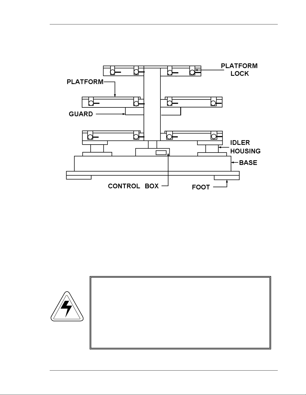
The Innova 5000 is a multiple tier shaker (see Figure 1 on the following page) that
utilizes an eccentric counterbalanced drive to provide horizontal plane rotary motion
in a 2-inch (51mm) circular orbit. A Proportional/Integral (PI) Microprocessor
controller with instantaneous digital feedback controls the speed over a range of 25350 RPM.
The shaker may be operated either continuously or in a timed mode via a
programmable timer for shaking periods of 0.1 hour to 99.9 hours.
The Innova 5000 is equipped with audible and visible alarms that are activated when
an alarm condition exists, as follows:
• The end of a timed run
• Deviation of shaking speed outside the tolerance limits
• Deviation of temperature outside the tolerance limits
A wide variety of platforms can be used with the Innova 5000. Dedicated platforms
are available for a variety of flask sizes. Universal platforms are also available. (See
Section 6 for a list of accessories.)
Innova 5000 M1196-0050 Operating Manual
Page 8
8
WARNING!
Figure 1: Front View
1.2 Universal Power Module
Voltage and frequency have been set prior to shipment. Innova shakers are available
in 100V, 120V, 220V and 240V, and can accommodate both 50 and 60 Hz
frequencies.
A voltage selector, which is incorporated in the power entry module, and a frequency
selector switch are used to select the appropriate voltage and frequency. This
universal system adapts to worldwide power requirements.
Do not plug the shaker into a power source until you check
the voltage and frequency settings.
Check the voltage selection on the power entry module (see
Figure 4) against the Caution label located over the power
cord connection and your electric power source.
Check the position of the frequency selector switch (see
Figure 4).
Also see Section 5.2, Changing Voltage & Frequency.
New Brunswick Operating Manual
Page 9
STATUS
LED DISPLAY
FUNCTION
KEYPAD
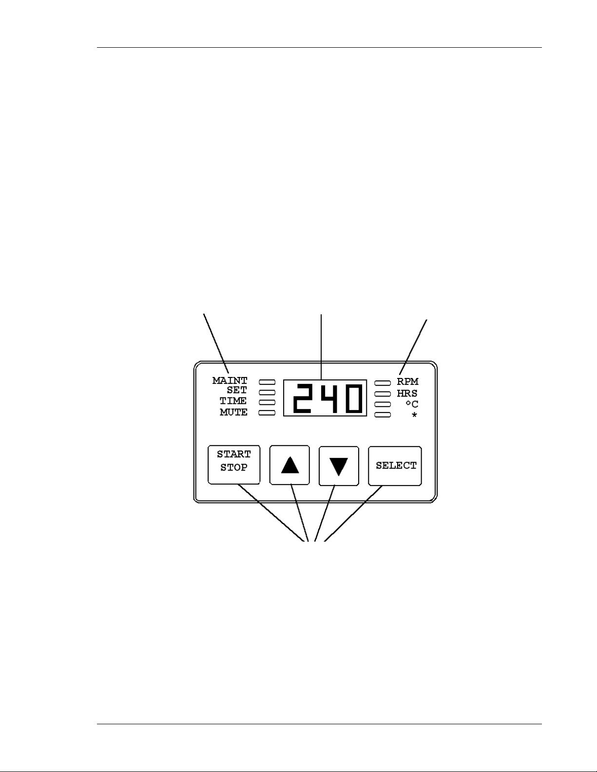
1.3 Control Panel
The control panel (see Figure 2) is located on the front of the instrument. It serves as
the operator interface. The keypad has four keys marked START/STOP, σ, τ and
SELECT. A three-digit LED display provides numeric values as well as some letter
codes. There are also four function indicator lights and four status indicator lights
on the control panel.
A general description of the display, user interface keys and indicators follows.
For operation of the control panel, see Section 3, Operation.
9
Figure 2: Control Panel
INDICATORS
INDICATORS
1.3.1 LED Display
The Innova control panel has a 3-digit LED display. During normal shaker
operation, the display will indicate:
• Shaker status (ON/OFF)
• Shaking speed
• Setpoints
Innova 5000 M1196-0050 Operating Manual
Page 10

10
• START/STOP
This key is used to start or stop the shaking
σ, τ
These keys are used to adjust the setpoint of a
• SELECT
This key is used to change the displayed
parameter.
• MAINT
Lights after 10,000 hours of use, to indicate need
• SET
Lights to indicate that the shaker is in the Set
• TIME
Lights to indicate that the timer is in operation.
• MUTE
Indicates the status of the audible alarm. When the
device is disabled.
• Hours remaining (timed run)
1.3.2 User Interface Keys
motion. It will also activate or stop the timer when
timed run is desired.
•
displayed parameter up or down. They also allow
the user to enter the Set mode for setpoint changes.
1.3.3 Status Indicators
for routine maintenance. Accumulated running
time is internally monitored and may be displayed
as a guideline.
mode, setpoints are being displayed, and setpoints
can be altered.
Innova shakers can be programmed to run for a
preset time from 0.1 hour to 99.9 hours. The timer
can be disengaged without stopping an ongoing
run.
New Brunswick Operating Manual
MUTE indicator is illuminated, the audible alarm
Page 11

1.3.4 Function Indicators
• RPM
Revolutions per minute
• HRS
Time remaining
• ºC
Not applicable
• *
Not applicable
1.4 Platform Assemblies
The Innova 5000 can be used with wide variety of New Brunswick 32½-inch x 26¾inch (82.5 cm x 68 cm) platforms which will accept a variety of clamps for flasks, test
tubes, etc. (see listing in Section 6).
11
1.5 Speed/Monitor Option
A Speed/Monitor Option (P/N M1194-9924) is available. This option allows the
connection of a chart recorder so that shaking speed can be documented. The analog
output for shaking speed is 0-3.5V (1V per 100 RPM).
The output can also be connected to a data logging computer with an analog data
acquisition card.
1.6 Heavy Duty Construction
1.6.1 Eccentric Drive
The eccentric drive used in the Innova shakers employs the same proven
technology that has reliably driven New Brunswick Scientific’s shakers for
over 30 years. This drive mechanism utilizes a counterweight system to
stabilize the rotary motion produced during operation. When the workload
moves in one direction, opposing forces are generated to stabilize the shaker.
This action will help eliminate the problem of “walking” that may occur with
less precisely balanced instruments. Vibrations are minimized and the life of
the unit is extended.
Innova 5000 M1196-0050 Operating Manual
Page 12

12
1.6.2 Bearings
Innova shakers employ sealed lubricated ball bearings of the highest quality.
Sealed bearings minimize the generation of airborne particulates that could be
disadvantageous in clean rooms or controlled environment areas.
This bearing design, which requires no maintenance, has performed reliably in
New Brunswick shakers for many years.
1.6.3 Motor
The Innova 5000 shaker uses a brushless ball bearing DC motor. This motor
provides high torque along with quiet, efficient operation and low
maintenance. The rugged motor has a rating of 1/3 horsepower.
1.7 Electronic Boards
The main control board for the Innova shaker has the following functions:
• Non-volatile memory for storage of key parameters during power interruption.
• Speed sensing, electronic commutation and power control for the brushless DC
drive motor.
• Maintaining an elapsed running time clock.
• Containing firmware for shaker control as well as recognition of an expansion
connector for option modules.
• Providing an operator interface via displays, audible alarm and connection to the
keypad module (keypad buttons and display graphics).
The optional speed/monitor module is designed to piggy-back onto the main board via
an expansion connector. It has the following functions:
• Control of analog power supplies.
• Providing remote monitoring capabilities by supplying analog outputs for speed
that are compatible with chart recorders and analog data acquisition systems.
New Brunswick Operating Manual
Page 13
2
Innova 5000 Catalog Number
Electrical Service Package
M1196-0001
100V 50/60Hz (M1196-0070)
M1196-0000
120V 50/60Hz (M1196-0070)
M1196-0002
220V 50/60Hz (M1196-0071)
M1196-0003
240V 50/60Hz (M1196-0071)
WARNING!
2
2.1 Unpacking
Upon unpacking the unit, inspect it carefully for any apparent damage that may have
occurred during transit. Immediately report any damage to the carrier and to the New
Brunswick Scientific Co., Inc. Service Department.
Do not discard the crate or packing material.
2.2 Voltage Configuration
Do not plug the shaker into a power source until you check
the voltage setting.
Determine the voltage of your unit by checking the voltage indicator and Caution label
on the rear of the unit. Confirm that the correct electrical service package is included
with the unit by referring to the table below (also see Section 5.2, Changing Voltage &
Frequency).
Voltage Configuration Table
I
NNSSTTAALLLLAATTIIOON
I
13
N
NOTE:
2.3 Space Requirements
Innova 5000 M1196-0050 Operating Manual
Use of the Innova shakers requires a platform which is separate i tem.
See Section 6 of this manual for a listing of available platf or m s. The
Innova 5000 uses 32½-inch x 26¾-inch (82.5 cm x 68 cm) platforms.
It is essential that the instrument be situated in an area where there is sufficient space
for the shaker and platform to clear walls and obstructions during operation. See
Figure 3 on the following page.
Page 14

14
Width
62 inches
157 cm
Depth
38 inches
96.5 cm
Height
53 inches
135 cm
Figure 3: Space Requirements
The dimensions of the Innova 5000 including a platform (excluding glassware) are:
2.4 Installation
1. With the unit in an operating position, adjust the hollow leveling screw (see
Figures 1 & 7) until the platform is level.
2. With the unit leveled, tighten the lock-nut on each leveling screw.
3. Prior to making electrical connections to the unit, set the power switch to OFF.
4. Make sure your power supply matches the requirements on the unit’s electrical
specification plate.
5. Connect the unit to your electrical service.
New Brunswick Operating Manual
Page 15

2.5 Electrical Connections
CAUTION!
CAUTION!
operation of this instrument.
Before making electrical connections, be sure to
follow these instructions:
1. Check the voltage and frequency selector switches on the rear of the unit to ensure
that they are set to the appropriate voltage and frequency.
2. Remove the Caution label from the rear of the unit.
3. Set the circuit breaker on the front of the unit to the OFF position.
ONLY THEN:
4. Connect the power cord to the power cord connection, then plug the unit into a
grounded electrical outlet.
15
A grounded electrical outlet is necessary for the safe
2.6 Platform Installation
A platform must be installed on the unit prior to use.
1. Place the platform on the shaker. Be sure to use the proper size platform for your
particular model shaker.
2. Tighten the platform locking levers.
2.7 Clamp Installation
Flask clamps purchased for use with universal platforms require installation.
Secure the base of the clamp to the platform with the correct type and number of
screws (refer to the clamp hardware application charts in Section 2.8).
All clamps are shipped complete with hardware.
Innova 5000 M1196-0050 Operating Manual
Page 16

16
UPPER GIRDLE
LOWER
PLATFORM
CLAMP
CLAMP BODY
Figure 4: 2- to 6-Liter Clamp Installation
MOUNTING
HOLES (5)
WITH GIRDLE
TUBES
GIRDLE WITH
GIRDLE TUBES
Clamps for 2- to 6-liter flasks are shipped with an additional girdle to keep the flasks
in place. To install 2- to 6-liter clamps, with reference to Figure 4 above:
1. Place the clamp on the platform and secure it in place with correct type of screws
(refer to the clamp hardware application charts on the following page).
2. Place the loose girdle around the upper portion of the clamp body so that it is held
in place by the clamp’s legs.
3. Insert the flask into the clamp.
NOTE:
The instructions and illustration above also apply to 2800 ml Fernbach
flask clamps.
2.8 Clamp Hardware
New Brunswick flask clamps are used on a variety of shaker platforms. Flat head
screws of different lengths and thread pitch are used to secure the clamp. The
following tables identify the proper screw for your shaker application by reference to
the head style.
(LEGS AND BASE)
New Brunswick Operating Manual
Page 17

17
Description
Part Number
Qty.
Application
10-24 x 5/8 (15.87 mm)
S2116-3101
1
3/4" (19.05 mm) thick
10-24 x 5/16 (7.9 mm) flat
S2116-3051
1
5/16" (7.9 mm) thick
10-32 x 5/16 (7.9 mm) flat
S2117-3050
1
all stainless steel
Description
Part Number
Qty.
Application
10-24 x 5/8 (15.87 mm)
screw
S2116-3101
5
3/4" (19.05 mm) thick
10-24 x 5/16 (7.9 mm)
S2116-3051
5
5/16" (7.9 mm) thick
10-32 x 5/16 (7.9 mm)
S2117-3050
5
all stainless steel
10 to 500 ml Clamp Hardware Application Chart
flat Phillips (+) head screw
Phillips (+) head screw
slotted (-) head screw
flat Phillips (+) head
flat Phillips (+) head
screw
flat slotted (-) head screw
wood platform
aluminum, phenolic and
stainless steel
platforms.
platforms
1- to 6-Liter Clamp Hardware Application Chart
wood platform
aluminum, phenolic
and stainless steel
platforms.
platforms
NOTE:
The 1- to 6-Liter chart also applies to 2800 ml Fernbach flask clamps.
Innova 5000 M1196-0050 Operating Manual
Page 18

18
New Brunswick Operating Manual
Page 19

3.1 Getting Started
To start the instrument, turn the power switch to the ON position.
When the shaker is running, the LED display will track the speed as it accelerates to
the last entered setpoint. The shaking action may be stopped or started by pressing the
START/STOP key.
NOTE:
At the higher speed ranges, we recommend that the platform s have a
30 percent minimum load to maintain a good balance condition.
3
3
19
O
PPEERRAATTIIOON
O
N
3.2 Continuous (Unlimited) Run
1. If the LED displays OFF, press the START/STOP key.
2. Press the SELECT key until RPM is lit.
3. Press either σ or τ to enter Set mode (set indicator will light).
4. Set the speed by using the σ or τ key until the desired setpoint is displayed. Holding
the σ or τ key will cause the setting to change more rapidly.
The setpoint may be changed at any time during a run without stopping the shaker by
following steps 2-4. During speed changes, the alarm may sound until the speed returns
to within 5 RPM of the setpoint.
3.3 Checking Setpoints
To check any setpoint:
1. Press the SELECT key until the desired indicator is lit.
2. Press either σ or τ to enter the Set mode and display the current setpoint.
NOTE:
Holding the σ or τ key for more than 0.5 second causes the setpoint to
change. Should this occur, resetting will be necessary.
Innova 5000 M1196-0050 Operating Manual
Page 20

20
3.4 Timed Functions
The shaker may be programmed to stop automatically after a preset time period of 0.1
hour to 99.9 hours. There must be power to the shaker in order to set the timer.
However, a timed run can be initiated while the unit is either shaking or stopped.
3.4.1 Setting the Timer
1. Press the SELECT key to light HRS.
2. Press either σ or τ to enter the Set mode, then set a time period of 0.1 to
99.9 hours.
3. While Set light is lit, press the START/STOP key to program the time (and
start the run).
The Time indicator will light and remain on for the duration of the run. At the
end of the timed run the display will read OFF, the time indicator will flash and
the audible alarm will sound.
The setpoint may be changed during a run without stopping the shaker by
following steps 1 and 2 above.
3.4.2 Cancelling the Timer
To cancel the timer without stopping the shaker:
1. Press the
SELECT key to light HRS.
2. Press either σ or τ to enter the Set mode, then set a time period of 0.1 to
99.9 hours.
3. Immediately press the
and the display will read
START/STOP key. The time indicator will go out
OFF.
3.4.3 Total Running Time
Innova shakers’ control modules continuously monitor the total running time
the shaker has been
ON, to track hours of usage.
To display the accumulated running time:
1. Select HRS using the SELECT key.
2. Simultaneously press the σ and τ keys.
New Brunswick Operating Manual
Page 21

The Set and Maint indicators will flash and the accumulated running time will
be displayed in hundreds of hours (i.e., “02” equals 200 hours; “102” equals
10,200 hours). This display will continue for 10 seconds and then default to
the previous mode readout.
After 10,000 hours of operation, the Maint indicator will light. Preventive
maintenance is recommended at this point. The light can be deactivated by
Eppendorf service personnel.
NOTE:
Alteration of the internal clock by unauthorized personnel wil l void the
warranty.
3.5 Alarm Functions
Innova shakers have an audible alarm which is activated at predetermined times. It is
possible to deactivate and reactivate the alarm, according to your needs.
21
3.5.1 Stopping the Alarm
When the alarm sounds, you can stop it by pressing the SELECT key and
changing to any other function.
3.5.2 Deactivating the Alarm
The alarm may be deactivated in the following way:
1. Press SELECT to light HRS.
2. Simultaneously press the σ and τ keys. The Set and Maint indicators will
flash.
3. While the Set and Maint indicators are flashing, press the START/STOP
key. The Mute indicator will light to advise that the audible alarm is
deactivated.
3.5.3 Reactivating the Alarm
The alarm may be reactivated in the following way:
1. Press SELECT to light HRS.
Innova 5000 M1196-0050 Operating Manual
Page 22

22
Pin Number
Signal Name
Scale
2
Ground
1V = 100 RPM
6
Speed
2. Simultaneously press the σ and τ keys. The Set and Maint indicators will
flash.
3. While the Set and Maint indicators are flashing, press the START/STOP
key. The Mute indicator will extinguish to advise that the audible alarm is
active.
NOTE:
The shaker may be started or stopped by pressing the START/STOP key.
When starting, the unit will automatically return to the last function and
speed setting.
The audible alarm will sound until the speed is within 5 RPM of the
setpoint. The alarm will not sound, however, while the shaker is
accelerating immediately following turning on the power.
3.6 Recorder Adaptation
To record speed, an auxiliary recorder (not supplied, but available from Eppendorf)
can be used. The recorder should have the following capabilities:
• For speed, each channel should have signal conditioning that accepts 0-5 volt
input.
• A mating connector is required on the recorder cable (not supplied, but available
from New Brunswick). This is a 9-pin male D subminiature connector, AMP
Amplimite HDP-20 series or equivalent.
Figure 5: Recorder Connector Pin-Out Diagram
(as seen from the rear of the unit)
New Brunswick Operating Manual
Page 23

4
CAUTION!
4
4.1 Cleaning
The unit may be cleaned using a cloth dampened with water or any standard
household or laboratory cleaner to wipe down its outer surfaces.
Never use abrasive or corrosive compounds to clean this
instrument, as they may damage the unit and void the
warranty.
M
M
23
AAIINNTTEENNAANNCCE
E
4.2 Preventive Maintenance
The Innova Shaker requires no routine maintenance on the part of the user.
The Maint indicator light goes on at the end of 10,000 hours of use. At that time,
contact your local Eppendorf Service Engineer or call the Eppendorf Service
Department. This periodic maintenance will keep your unit in premium condition.
Innova 5000 M1196-0050 Operating Manual
Page 24

24
New Brunswick Operating Manual
Page 25

5
WARNING!
5
The following section describes basic service procedures and provides instructions to install
optional features. All of these procedures must be performed by a qualified service
engineer.
BEFORE any service or maintenance intervention on the
instrument, the Service Engineer must turn the power switch
OFF and disconnect the power cord.
5.1 Fuse Replacement
S
EERRVVIICCE
S
25
E
The unit design incorporates a circuit breaker, which is used as an ON/OFF switch.
There is one fuse on the rear of the control box to protect the control circuitry.
To remove a fuse, insert a small flat-bladed screwdriver and turn counter-clockwise
until it disengages and the fuse holder springs free. Check the fuse and, if it has
failed, replace the fuse with a new fuse as identified in the Spare Parts List (see
Section 5.1). Spare fuses are supplied with the unit.
5.2 Changing Voltage & Frequency
Innova 5000 is set to the appropriate line voltage and frequency prior to shipment.
The voltage selector switch, however, is a universal power-entry device which can be
reset to adapt to worldwide power requirements.
If it is necessary to change the voltage or frequency, the Service Engineer will:
1. Set the ON/OFF switch (located on the control panel of the unit) to OFF.
2. Disconnect the unit from the power source.
3. Use a flat-bladed screwdriver to raise the lock tab under the voltage selector and
remove the fuse drawer portion of the power entry module (see Figure 6 on the
following page).
4. Remove the fuse holder, rotate it until the appropriate voltage appears in the fuse
drawer window, and replace the fuse holder.
Innova 5000 M1196-0050 Operating Manual
Page 26

26
Figure 6: Power Entry Module
5. Reinstall the fuse drawer in the power entry module.
6. Set the frequency slide switch to appropriate position.
7. Check that the proper power cord is available for the voltage selected.
8. Plug the power cord into the power cord connection on the unit and the power
source.
9. Set the
ON/OFF switch to the ON position.
The unit is ready for operation.
5.3 Belt Replacement
When a new drive belt is needed, the Service Engineer will: (see Figure 1)
1. Set the power switch to
2. Place 3-inch strips of masking tape on the new drive belt, every 6 inches across the
belt. This is required in order to hold the belt in place on the large pulley during
installation.
3. Pass the new drive belt (#R-472) through the opening in the side of the base of the
shaker (see Figure 1).
4. Lay the belt in the groove of the large pulley and press the tape to hold in place.
5. Rotate large pulley and fasten next piece of tape on belt to pulley.
6. Continue this until the belt is installed completely around the large pulley.
7. Loosen the four bolts that hold the motor in place.
8. Slide the motor towards the center of the shaker.
9. Reach inside the shaker and place the belt in the motor pulley.
10. Pull the motor away from center of shaker and tighten the four bolts.
11. Reach inside the base and remove all tape from pulley and belt.
The unit is now ready for operation.
OFF and disconnect the power cord.
New Brunswick Operating Manual
Page 27

5.4 Main Bearing Housing Assembly Replacement
LOWER
BEARING
If it becomes necessary to replace the main bearing housing assembly, the Service
Engineer will, with reference to Figures 7, 8 & 9 below:
1. Set the power switch to OFF position and disconnect the power cord.
2. Remove all platforms from the unit.
3. Remove all 16 bolts that hold the idler housing to the base.
4. Remove the four bolts that hold the main shaft to the the lower main housing.
Figure 7: Frame End View
27
5. Remove the frame from the unit by raising the unit up to disengage the locating
pin from the lower main housing.
Innova 5000 M1196-0050 Operating Manual
Page 28

28
POST HOUSING
O RING
6. Remove the drive belt.
7. Remove the main drive pulley.
8. Remove the bolts that hold the main housing to the base.
9. Replace in reverse order.
5.5 Idler Housing Repair
If it becomes necessary to repair the idler assembly, the Service Engineer will follow
the procedure below, with reference to Figures 7, 8 & 9. Each idler eccentric shaft
may be individually removed without removing the upper shaking frame or platform
assembly. For safety reasons, however, only one idler eccentric shaft at a time should
be removed.
Figure 8: Idler Assembly
New Brunswick Operating Manual
To remove an idler eccentric shaft:
1. Set the power switch to OFF position and disconnect the power cord.
2. Remove all trays from the lower section of the upper frame assembly.
Page 29

29
3. Remove the four bolts securing the upper portion of the idler eccentric housing to
the frame.
4. Remove the four bolts holding the lower portion of the idler eccentric shaft
housing to the base of the shaker.
5. With all bolts removed, the idler eccentric shaft housing may be removed by
sliding it out from between the shaker base and the platform.
6. The eccentric shaft may now be removed from the idler eccentric shaft housing for
repair or bearing replacement.
7. To reassemble, bolt the idler housing to the frame.
8. Position the idler eccentric shaft to face in the same direction as the other idler
shafts, and replace all bolts previously removed from the base and idler eccentric
shaft housing. Do not tighten screws.
9. To achieve alignment, turn the drive pulley or main counterweight manually for
several revolutions. Then, tighten the screws just enough to snug up the idler
assembly to the base.
Figure 9: Main Housing Assembly
10. Reconnect the power cord, set the power switch ON, allow the shaker to turn
slowly, and hand tighten all bolts (while the shaker slowly rotates).
11. Turn up the speed and allow the shaker to run for a few minutes. If the rotation is
smooth, turn the shaker OFF and tighten the bolts.
12. With the shaker OFF, replace the trays on the upper frame assembly.
Innova 5000 M1196-0050 Operating Manual
Page 30

30
5.6 Motor Assembly Replacement
Should a new motor become necessary, the Service Engineer will:
1. Set the power switch to OFF position and disconnect the power cord.
2. Remove the drive belt.
3. Disconnect the motor power cord from the motor.
4. Remove the four bolts that hold the motor plate to the base.
5. Remove the motor from the unit.
6. Remove the motor pulley.
7. Remove the four bolts that hold the motor to the motor plate.
8. Replace the motor on the plate.
9. Replace the motor pulley.
10. Replace the motor, following the steps in reverse order.
11. Line up the belt and check for a ½-inch drop in the belt.
5.7 Upper Shaft Assembly Removal
1. Set the power switch to OFF position and disconnect the power cord.
2. Remove all platforms from the unit.
3. Remove counterweight guard.
4. Remove counterweight.
5. Remove upper bearing (see Figure 10 on the following page).
6. Remove the four main shaft bolts.
7. Remove the four upper shaft bolts.
8. Remove upper shaft assembly (see Figure 11).
9. Replace assemblies in the reverse order.
10. Replace upper shaft assembly, making sure the location pin from the lower main
housing is engaged.
11. Replace the main shaft bolts and tighten the bolts.
12. Install the upper shaft bolts, hand tight.
13. Install the upper bearing (see Figure 10).
14. Reinstall the counterweight. Make sure the counterweight key is in place.
15. Reinstall the counterweight cover.
16. Turn the unit by hand to make sure the counterweight clears the counterweight
guard.
17. If the counterweight clears the guard, plug the unit in, turn the power ON, and set
the speed to 25 rpm. If the unit runs smoothly, turn the power OFF and tighten the
upper shaft bolts and the upper bearing bolts.
18. Reinstall the platforms.
19. Turn the power ON again, set the speed to 100 rpm. If the unit runs smoothly,
check it again at 250 rpm. If the unit runs well, stop it, turn the power OFF.
New Brunswick Operating Manual
Page 31

Figure 10: Upper Bearing Assembly Removal
31
Innova 5000 M1196-0050 Operating Manual
Page 32

32
Figure 11: Upper Shaft Assembly Removal
5.8 Speed/Monitor Option
The Speed/Monitor option (#M1194-9924) offers remote monitoring, with a 0-5V
analog recorder output for speed. Can be used with an external chart recorder or
computer which has a data acquisition card.
New Brunswick Operating Manual
Page 33

6
Catalog
Number
Platform Flask Size
Flasks per
Platform
Flasks per
Shaker
M1196-9447
Universal1
--
--
M1196-9908
10 mL
300
1,800
M1196-9909
25 mL
248
1,488
M1196-9910
50 mL
161
966
M1196-9900
125 mL
99
594
M1196-9901
250 mL
64
384
M1196-9902
500 mL
42
252
M1196-9903
1L
23
138
M1196-9904
2L2
14
70
M1196-9905
2.8L
9
54
M1196-9906
4L3
8
16
M1196-9907
6L3
8
16
Catalog Number
Clamp Type
ACE-105
10 ml Erlenmeyer
ACE-255
25 ml Erlenmeyer
ACE-505
50 ml Erlenmeyer
ACE-125S
125 ml Erlenmeyer
ACE-250S
250 ml Erlenmeyer
ACE-500S
500 ml Erlenmeyer
ACE-1000S
1.0L Erlenmeyer
ACE-2000S
2.0L Erlenmeyer
ACE-4000S
4.0L Erlenmeyer
ACE-6000S
6.0L Erlenmeyer
ACFE-2800S
2800 ml Fernbach
ACSB-500S
500 ml Media Bottle
ACSB-1000S
1.0L Media Bottle
6
6.1 Platforms
All of the following platforms are available for use with the Innova 5000:
A
A
CCCCEESSSSOORRIIEESS
&
&
S
EERRVVIICCEE
S
P
AARRTTSS
P
33
1 Flask clamps must be ordered separately for Universal Platforms.
2 Only the front half of this platform can be used on the bottom tier.
3 For use on top tier only. Maximum 16 flasks on top 2 tiers.
6.2 Flask Clamps
All of the following accessory clamps are made of stainless steel:
For accessory clamp mounting hardware kits, see the tables in Section 2.8.
Innova 5000 M1196-0050 Operating Manual
Page 34

34
Part Number
Description
Qty
P0380-3830
Fuse .200
1
M1196-3500
Main Bearing Housing Assembly
1
M1196-3400
Steady Rest Bearing Assembly
1
M1196-3100
Idler Housing Assembly
1
M1196-3200
Upper Drive Shaft Assembly
1
R-472
Belt
1
P0180-0250
Bearing
1
B-208
Bearing
1
M1196-9914
Motor
1
M1196-7001
Motor Drive Assembly
1
M1196-5300
Transformer Assembly
1
M1196-9911
Main Control PCB
1
6.3 Service Parts
New Brunswick Operating Manual
Page 35

Shaking
Speed
25-350 rpm
Motion
2" (50.8 mm) diameter circular orbit
Indication
LED digital electric display, 1 rpm increments
Setpoint & Control
Digital adjustment with PI microprocessor control
and instantaneous visual feedback
Accuracy
± 1 rpm (see NOTE below)
Drive
Eccentric counterbalanced ball bearing drive
Keypad Timer
Programmable shaking periods from 0.1 hour to 99.9 hours by a digital timer that
shuts off at the end of period and energizes status light.
Timer counts down and digital display indicates remaining time. Can be
accumulated running time for service information.
Operating Ambient Environment
0°C - 60°C, 90% relative humidity, non-condensing
Self-Diagnostic Status
Warning signal (audible and visible) indicates when shaking speed deviates more
deactivated/reactivated by the operator.
Remote Monitoring
Optional chart recorder output for speed 0-5V, 1V per 100 rpm.
Accuracy ±25mV.
Automatic Restart
Unit will automatically restart after undesired power interruption. Setpoints are
display.
Motor
1/3 HP, brushless ball bearing DC motor.
Electrical Service
100V, 120V, 220V, 240V. All voltages 50/60 Hz 150 VA.
Universal power entry system adapts to U.S. or international requirements.
Electrical Protection
Main power control circuits provided with separate fuse.
NOTE:
At 25-350 rpm, the unit w ill perform to specifications with up to ±10% line
voltage fluctuation.
7
7
35
S
PPEECCIIFFIICCAATTIIOONNS
S
S
deactivated for continuous operation. Additionally, unit will display total
than 5 rpm and when timer operation has expired. Audible alarm can be
maintained by non-volatile memory. Interruption is indicated by a flashing LED
Innova 5000 M1196-0050 Operating Manual
Page 36

36
Dimensions
62" (157 cm) Wide x 38" (96.5 cm) Deep x 53" (135 cm) High to platform surface.
Construction
Heavy gauge steel, phosphate coated and texture painted frame.
Weight
Net: 2,000 lbs. (907 kg)
Gross: 2,200 lbs. (998 kg)
Platform Dimensions
32.5" x 26.75" (82.5 cm x 68 cm)
New Brunswick Operating Manual
Page 37

8.1 Control Schematics
BR001
2500 f
C001
+
R001
3K 20W
m
PHASE A
PHASE B
PHASE C
TACH A
TACH B
TACH C
V REF. (+)
V REF. (- )
J3-3
J3-2
J3-1
J2-3
J2-4
J2-5
J2-6
J2-7
M001
J4-3
J4-4
MOTOR DRIVE
PCB 001
J4-2
RED
GRN
LED 001
LED 002
J4-1
J1-2
J1-4
J1-3
TR1
REC1
REC1
TR1
FIBER OPTI C CABLE
T002
5
8
2
1
J1-6
J1-5
RUN/STOP
INC
DEC
SELECT
J4-1
J4-2
J4-3
J4-4
J4-5
PCB 002
MAI N
CONTROL
GRY
RED
WHT/VIOWHT/BLK
WHT/VIO
WHT/VIO
VIO
F001
.20 AMP
YEL
BLK
WHT/BLK
WHT/BLK
T001
432
1
S001
250 120 100220 C
A
RED
BLU
GRY
VIO
RED WHT/ BL K WHT
WHT/BLK
WHT/ BL K
RED
BLU
BLK
GRY
MOV001
VIO
AC CONN.
N
L
G
GRN
N
L
21
BLK
WHT
11
VOLTAGE
SELECTOR
SWIT CH
22
10A
CB001
12
LINE
LF001
LOAD
BLK
RED
J1-14
J1-15
J1-16
J1-17
J1-20
J1-21
37
8
8
D
RRAAW
D
WIINNGGSS
Innova 5000 M1196-0050 Operating Manual
Page 38

38
New Brunswick Operating Manual
Page 39

Alarm, 21
Deactivating the, 21
Reactivating the, 21
Stopping the, 21
A
Installation, 13, 14
Keypad, 9
9
9
K
L
I
NNDDEEX
I
39
X
B
Bearings, 12
Belt Replacement, 26
C
Cancelling the Timer, 20
Changing Voltage & Frequency, 25
Checking Setpoints, 19
Clamp Hardware, 16
Clamp Hardware Application Charts, 17
Clamp Installation, 15
Clamps, 33
Cleaning, 23
Continuous Run, 19
Control Panel, 9
Control Schematic, 37
D
Deactivating the Alarm, 21
Dimensions, 14
E
Eccentric Drive, 11
Electrical Connections, 15
Electronic Boards, 12
F
Flask Clamps, 33
Frequency
Changing the, 25
Frequency Selection, 8
Front View, 8
Function Indicator Lights, 9, 11
Fuse Replacement, 25
LED Display, 9
M
Main Bearing Housing Replacement, 27
Main Control Board, 12
Maintenance, 21, 23
Motor, 12
Motor Replacement, 30
P
Platform Assemblies, 11
Platform Installation, 15
Platforms, 33
R
Reactivating the Alarm, 21
Recorder Adaptation, 22
Recorder Connector, 22
Remote Monitoring, 32
S
Service Parts, 34
Service Procedures, 25
Setting Setpoints, 19
Setting the Timer, 20
Shipping Damage, 13
Space Requirements, 13
Specifications, 35
Speed/Monitor, 32
Starting the Shaker, 19, 22
Status Indicator Lights, 9, 10
Stopping the Alarm, 21
Stopping the Shaker, 22
T
I
Idler Housing Repair, 28
Innova 5000 M1196-0050 Operating Manual
Table of Contents, 5
Timed Run, 20
Timer, 20
Page 40

40
Cancelling the, 20
Setting the, 20
Total Running Time, 20
U
Universal Power Entry Module, 25
Universal Power Module, 8
Unlimited Run, 19
Upper Shaft Assembly Removal, 30
User Interface Keys, 10
V
Voltage, 13
Changing the, 25
Voltage Selection, 8
New Brunswick Operating Manual
Page 41

41
Innova 5000 M1196-0050 Operating Manual
Page 42

Evaluate your manual
Give us your feedback.
www.eppendorf.com/manualfeedback
Your local distributor: www.eppendorf.com/worldwide
Eppendorf AG · Hamburg · Germany · Tel: +49 40 538 01-0
Application Support E-mail: support@eppendorf.com
Eppendorf North America, Inc. · USA · Tel: +1 516 334 750 0
Toll free phone: +1 800 645 3050 menu option 2
E-mail: techserv@eppendorf.com
www.eppendorf.com
 Loading...