

Page 1

Guide to Operations
Galaxy R Series
48 R CO
MANUAL No: CO48R-0050
Incubator
2
Revision B
February 16, 2010
New Brunswick Scientific PO Box 4005 44 Talmadge Rd. Edison, 08818-4005 USA
1.800.631.5417 1.732.287.1200 bioinfo@nbsc.com
www.nbsc.com
Page 2

2
INTERNATIONAL OFFICES:
BELGIUM
New Brunswick Scientific NV-SA
Stationsstraat 180/4
3110 Rotselaar
België/Belgique
Tel: +32 (0)16 56 28 31
Fax: +32 (0)16 57 27 53
E-mail: sales@nbsnv-sa.be
CHINA
New Brunswick Scientific
A903 Yin Hai Building
No. 250, Cao Xi Road
Shanghai 200235, P.R. China
Tel: +86 21 6484 5955 or 5966
Fax: +86 21 6484 5933
E-mail: nbschc@online.sh.cn
FRANCE
Eppendorf France SARL
60, route de Sartrouville
78230 Le Pecq
France
Tel: +33 (0)1 30 15 67 40
Fax: +33 (0)1 30 15 67 45
E-mail: eppendorf@eppendorf.fr
GERMANY
Eppendorf Vertrieb Deutschland GmbH
New Brunswick Produkte
Peter-Henlein-Strasse 2
D-50389 Wesseling-Berzdorf
Deutschland
Tel: +49 (0)2232 418 0
Fax: +49 (0)2232 418 155
E-mail: vertrieb@eppendorf.de
THE NETHERLANDS
New Brunswick Scientific BV
Kerkenbos 1101, 6546 BC Nijmegen
Nederland
Tel: +31 (0)24 3717 600
Fax: +31 (0)24 3717 640
E-mail: sales@nbsbv.nl
UNITED KINGDOM
New Brunswick Scientific (UK) Ltd.
17 Alban Park, Hatfield Road
St. Albans, Herts. AL4 0JJ
United Kingdom
Tel: +44 (0)1727 853 855
Fax: +44 (0)1727 835 666
E-mail: bioinfo@nbsuk.co.uk
CO48R-0050 Galaxy R Series 48 R Personal Size CO2 Incubator User’s Guide
Page 3

3
CAUTION!
This equipment must be operated as described in this manual.
If operational guidelines are not followed, equipment damage
and personal injury can occur.
Please read the entire User’s Guide before attempting to use this
incubator.
Do not use this equipment in a hazardous atmosphere or with
hazardous materials for which the equipment was not designed.
New Brunswick Scientific (NBS) is not responsible for any
damage to this equipment that may result from the use of an
accessory not manufactured by NBS.
New Brunswick Scientific User’s Guide
Page 4
4
,
Copyright Notice
New Brunswick Scientific
Box 4005 44 Talmadge Road
Edison, New Jersey 08818-4005
© Copyright 2010 New Brunswick Scientific
All Rights Reserved.
Reproduction, adaptation, or translation without prior written permission from New
Brunswick Scientific is prohibited.
Disclaimer Notice
New Brunswick Scientific reserves the right to change information in this
document without notice. Updates to information in this document reflect our
commitment to continuing product development and improvement.
Manual Conventions
NOTE:
CAUTION!
WARNING!
WARNING!
CRUSH
WARNING!
Notes contain essential information that deserves
special attention.
Caution messages appear before procedures which, if
caution is not observed, could result in damage to the
equipment.
Warning messages alert you to specific procedures or
practices which, if not followed correctly, could result
in serious personal injury.
This particular Warning message represents a potential
electrical hazard.
This particular Warning message, whether found in the
manual or on the incubator means HOT SURFACE–and
therefore represents a potential danger to touch.
Crush Warning messages alert you to specific
procedures or practices regarding heavy objects
not followed correctly, could result in serious personal
injury .
This symbol on the incubator is a reminder that it is of
essential importance to read the user manual.
which
CO48R-0050 Galaxy R Series 48 R Personal Size CO2 Incubator User’s Guide
Page 5

5
W A R R A N T Y
Every Instrument manufactured by
New Brunswick Scientific (NBS) is warranted to be free
from defects in material and workmanship. This apparatus, with
the exception of glassware, lamps and electrodes (where supplied),
is warranted for 2 years against faulty components & assembly and
our obligation under this warranty is limited to repairing or replacing
the instrument or part thereof which shall within 2 years following
date of shipment prove to be defective after our examination.
Incubator accessories are warranted for 1 year. This warranty does
not extend to any NBS products which have been subjected
to misuse, neglect, accident or improper installation or
application; nor shall it extend to products which
have been repaired or altered outside the NBS
factory without prior authorization from the
New Brunswick Scientific.
New Brunswick Scientific User’s Guide
Page 6

6
CO48R-0050 Galaxy R Series 48 R Personal Size CO2 Incubator User’s Guide
Page 7

7
TABLE OF CONTENTS
1 INTRODUCTION............................................................................................................11
2 UNPACKING & INSTALLATION ...............................................................................13
2.1 INSPECTION OF BOXES.................................................................................................13
2.2 UNPACKING................................................................................................................. 13
2.3 UTILITIES ....................................................................................................................14
2.4 LOCATION ...................................................................................................................14
2.5 INSTALLING THE FEET .................................................................................................15
2.6 SETTING UP................................................................................................................. 15
3 OPERATION....................................................................................................................19
3.1 CONTROL PANEL .........................................................................................................19
3.2 PREPARING FOR OPERATION........................................................................................19
3.3 USING THE HUMIDITY TRAY & HUMIDITY CONTROL..................................................20
3.4 PROGRAMMING............................................................................................................21
3.4.1 Temperature and CO2 Level...............................................................................21
3.4.2 User Access Code............................................................................................... 22
3.5 REFERENCING CO
3.6 USER SETTINGS.......................................................................................................... 23
3.6.1 DATE/TIME ADJUST ........................................................................................24
3.6.2 AUDIO VOLUME ADJUST ............................................................................... 24
3.6.3 PROGRAMMABLE CO2 AUTOZERO...............................................................24
3.6.4 DATALOGGER ..................................................................................................25
3.6.5 POWER FREQUENCY ......................................................................................25
3.6.6 DISABLE ............................................................................................................ 25
3.6.7 DISINFECTION (Model Option)....................................................................... 26
3.7 DATALOGGER
3.7.1 ALARM EVENTS................................................................................................26
3.7.2 TEMPERATURE GRAPH + DOOR OPEN BAR CHART.................................27
3.7.3 CO2 GRAPH + DOOR OPEN BAR CHART...................................................... 28
3.7.4 DIAGNOSTIC CHAMBER ELEMENT GRAPH ................................................ 28
3.7.5 DIAGNOSTIC DOOR GRAPH........................................................................... 28
3.7.6 DIAGNOSTIC DOOR ELEMENT GRAPH........................................................29
3.7.7 RESTART GRAPHIC RECORD.........................................................................29
3.8 CHAMBER
ALARMS MENU SCREEN....................................................................... 29
3.8.1 Chamber Alarm System Function....................................................................... 30
3.9 D
IAGNOSTIC MENU SCREEN........................................................................................ 32
3.10 HELP MENU SCREEN ................................................................................................33
SENSOR WITH AUTOZERO............................................................. 23
2
SCREEN ...........................................................................................26
4 ROUTINE MAINTENANCE..........................................................................................34
4.1 G
4.2 D
New Brunswick Scientific User’s Guide
ENERAL NOTES.........................................................................................................34
AILY CHECKS............................................................................................................34
Page 8

8
4.3 MONTHLY CHECK .......................................................................................................34
5 CLEANING & DISINFECTING.................................................................................... 36
5.1 C
5.2 D
LEANING ...................................................................................................................36
ISINFECTING.............................................................................................................. 36
5.3 HIGH TEMPERATURE DISINFECTION............................................................................ 38
6 SPECIFICATIONS..........................................................................................................39
7 OPTIONS & ACCESSORIES.........................................................................................41
7.1 O
7.2 A
PTIONS ......................................................................................................................41
VAILABLE ACCESSORIES........................................................................................... 41
8 APPENDIX A: OPTIONS..............................................................................................42
8.1 O
8.2 H
PTIONS ......................................................................................................................42
IGH TEMPERATURE DISINFECTION............................................................................42
8.3 HIGH TEMPERATURE DISINFECTION OPTION WITH OXYGEN CONTROL....................... 45
8.3.1 Oxygen Sensor Removal..................................................................................... 45
8.3.2 Oxygen Sensor Replacement .............................................................................. 45
8.4 BMS RELAY CONTACT ALARM OPTION...................................................................... 46
8.5 O
CONTROL (1-19%) .................................................................................................47
2
8.5.1 Setting Up the N2 Tank.......................................................................................47
8.5.2 Setting Up Oxygen Control ................................................................................48
8.5.3 Operating Guidelines ......................................................................................... 50
8.5.4 Referencing to Atmosphere ................................................................................50
8.5.5 Replace Sensor Soon .......................................................................................... 51
8.5.6 Replace Sensor Now........................................................................................... 51
8.5.7 Removing & Replacing O2 Sensor......................................................................52
8.5.8 Replacing the Filter Disc ...................................................................................53
8.5.9 Troubleshooting the Oxygen Sensor...................................................................55
8.5.10 Oxygen Control Specifications........................................................................... 55
8.6 O
8.6.1 Setting Up the N
8.6.2 Setting Up O
CONTROL (0.1-19%) ..............................................................................................56
2
Tank.......................................................................................56
2
Control ........................................................................................56
2
8.6.3 Enabling or Disabling O2 Control .....................................................................57
8.6.4 Alarms.................................................................................................................58
8.6.5 Referencing to Atmosphere ................................................................................58
8.6.6 Programming Desired O2 Level.........................................................................58
8.6.7 Precautions......................................................................................................... 59
8.7 O
CONTROL (1-95%) .................................................................................................59
2
8.7.1 Setting Up the N2 Tank.......................................................................................60
8.7.2 Setting Up O2 Control ........................................................................................60
8.7.3 Enabling or Disabling O
8.7.4 Important Notes for O
Control .....................................................................61
2
Levels >80%.................................................................62
2
8.7.5 Alarms.................................................................................................................62
8.7.6 Referencing to Atmosphere ................................................................................63
8.7.7 Programming Desired O
Level.........................................................................63
2
CO48R-0050 Galaxy R Series 48 R Personal Size CO2 Incubator User’s Guide
Page 9

9
8.7.8 Other Precautions ..............................................................................................63
8.7.9 Specifications......................................................................................................63
8.8 O2 SENSOR REPLACEMENT ..........................................................................................63
9 CE CERTIFICATION..................................................................................................... 64
10 DRAWINGS & TABLES................................................................................................65
10.1 INDEX OF DRAWINGS................................................................................................... 65
10.2 INDEX OF TABLES........................................................................................................65
11 INDEX..............................................................................................................................66
New Brunswick Scientific User’s Guide
Page 10

10
CO48R-0050 Galaxy R Series 48 R Personal Size CO2 Incubator User’s Guide
Page 11

11
11
The Galaxy 48 R CO2 incubator is microprocessor controlled and designed to ensure accurate
and reliable operation. The incubator incorporates a large, back-lit LCD display, touchsensitive keypad and sophisticated control system that allows for easy programming, control
and monitoring of the chamber conditions. The display also provides for graphical viewing of
system data, on-screen messaging and help files to simplify operation and maintenance.
A direct heating system, utilizing a thermal heating element, completely surrounds the
incubator, providing an even temperature within the seamless chamber. The independently and
directly heated outer door is designed to ensure an even distribution of heat, thereby
eliminating condensation on the inner door. This system ensures a rapid, controlled return to
optimum chamber conditions after a door opening while also preventing any overshoot. The
incubator’s direct heat system provides for optimal use of laboratory space by allowing the
most efficient internal volume for the footprint of the instrument. A viewing window within
the door allows for sample viewing without disturbing chamber conditions.
A solid-state infrared sensor is used to control the level of CO2, providing excellent reliability
and remaining unaffected by humidity. The CO2 system has a programmable automatic zero
system (AutoZero) to re-reference the sensor baseline to atmospheric CO2 levels at regular
intervals. A small pump supplies HEPA-filtered atmospheric gas to the sensor. The chamber
atmosphere within the sensor is completely displaced, allowing the control system to
automatically reference the sensor, after which the pump is switched off, allowing the chamber
atmosphere to homogenize back into the sensor. This provides for accurate CO2 control
without disturbing the chamber environment.
An independently controlled water tray at the bottom of the incubator allows a high, uniform
relative humidity while preventing condensation in other parts of the chamber. Perforated
shelves are provided as standard to facilitate a much faster recovery of RH conditions in the
chamber than with unperforated shelves.
The seamless 48-liter chamber and all internal components are manufactured from polished
stainless steel. The shelves (which are non-tip), shelf racks and humidity tray are easily
removed without tools for thorough cleaning and are capable of being sterilized. Air
circulation is achieved without the use of a fan, eliminating ductwork (a potential source of
contamination), simplifying cleaning, eliminating vibration, and reducing small sample
evaporation within the chamber. The outer shell of the incubator is manufactured from zincplated stove enamelled steel to give a durable corrosion-resistant finish.
I
NNTTRROODDUUCCTTIIOON
I
N
New Brunswick Scientific User’s Guide
Page 12

12
The Galaxy 48 R model contains many standard features usually seen as options. It has a
sealing inner door with a cam action lock to allow visualization of the cultures without
compromising the internal atmosphere. This is also available as a split 4- or 8-inner-door
option (to coordinate with shelves), which is ideal for critical hypoxic studies. In addition,
there is a 25mm access port now standard to allow for seamless integration of independent
probes or other equipment through the chamber. Lastly, NBS has included an RS232 port as
standard on all Galaxy R series incubators. This port will communicate with any computer
through a hyperlink access or can be used to externally datalog the incubator through NBS
software.
The incubator incorporates a two-level alarm system. The chamber-monitoring alarms are
programmable and will alert you if temperature or CO2 have not recovered within a preset time
after the door has been opened. If it is not required, this system can be disarmed. The system
alarms occur only if a system component problem has developed that requires user intervention
to rectify. The incubator also incorporates an over-temperature safety system that operates
independently from the main control system.
The incubator features multiple options that can be installed to simplify maintenance and
provide superior control over experimental conditions. For example, high-temperature
disinfection quickly and conveniently disinfects the incubator’s chamber at 120oC, without the
need to remove interior components or the CO2 sensor. A humidity tray warning system
warns the user before the humidity tray runs out of water, preventing dehydration of samples.
Oxygen control provides for conditions that require above- or below-ambient oxygen levels.
These and other options and accessories provide for a uniquely flexible CO2 incubator capable
of meeting the most demanding requirements.
CO48R-0050 Galaxy R Series 48 R Personal Size CO2 Incubator User’s Guide
Page 13
13
22
2.1 Inspection of Boxes
After you have received your order from New Brunswick Scientific, inspect the boxes
carefully for any damage that may have occurred during shipping. Report any damage
to the carrier and to your local NBS Sales Order Department or distributor immediately.
2.2 Unpacking
CRUSH WARNING!
At least two people are required to safely lift your 48 R.
Disassemble the wooden shipping crate and remove the protective packing. Save the
packing materials for possible future use, and be sure to save this User’s Guide for
instruction and reference.
To simplify lifting the incubator, leave it on the pallet. You must have at least one
person at either side to safely lift the incubator. Supported by the base only, remove the
incubator by lifting it from the delivery pallet.
Locate and remove the parts stored in the Humidity Tray.
If any part of your order was damaged during shipping, is missing, or fails to operate,
please fill out Customer Satisfaction Form 6300 (packed in the envelope with your
warranty card) and return it by fax or mail. You can also call New Brunswick
Scientific’s or your distributor’s service department.
Using your NBS packing list, verify that you have received the correct materials and
that nothing is missing.
Table 1 on the following page outlines the accessory items that are supplied with your
new incubator:
U
NNPPAACCKKIINNGG
U
&
&
I
NNSSTTAALLLLAATTIIOON
I
N
New Brunswick Scientific User’s Guide
Page 14
14
Table 1: Accessories Provided
Quantity Item Notes
3 Non-tip Shelves Packed Separately
2 Wire Shelf Racks Packed Separately
1 Humidity Tray Packed Separately
14 Silicone Rubber Suction Feet Installed
1 White porous CO2 Sensor Cover Installed
1 Black Sensor Cover* Installed
1 Power Cord Packed in accessories bag
3 meters,
9.8 feet
2 Hose Clips Packed in accessories bag
1 AutoZero HEPA Filter Packed in accessories bag
4 Adjustable Feet Packed in accessories bag
4 Anti-slip Pads for adjustable feet Packed in accessories bag
1 User Manual Provided
PVC Tubing, ~1/4-inch or 6mm bore,
with an inline CO
HEPA-filter
2
Packed in accessories bag
connected, ready for use
* There is a holder at the rear of the incubator to store the black sensor cover.
WARNING!
Anytime you touch or handle the white CO2 sensor cover, be sure to
wear gloves, and do not later touch those gloves to your face. Discard
or wash the gloves.
2.3 Utilities
In order to use the incubator, you will need:
Table 2: Utilities
Utility Requirement
Electricity
CO2 Gas Cylinder with 100% CO2 vapor withdrawal, together with a two-stage regulator
2.4 Location
The incubator is designed to operate at a chamber temperature of 4.0°C above ambient,
and at an absolute minimum ambient temperature of 15°C if the incubator is being used
at 37°C. Care should be taken to avoid placing the incubator in a position that may
affect its performance, such as those listed below.
100/120V, 50/60 Hz grounded electrical supply with minimum capacity of 6
amps (or 8 amps for High Temperature Disinfection Models)
OR
220/240V, 50 Hz grounded electrical supply with minimum capacity of 3 amps
(or 5 amps for High Temperature Disinfection Models)
for pressure control to 5 psi or 0.35 bar
CO48R-0050 Galaxy R Series 48 R Personal Size CO2 Incubator User’s Guide
Page 15

15
DO NOT place the incubator:
• Directly under, beside or within the air-flow of heating or air-conditioning
ducts, or other drafts;
• Directly beside heat-generating equipment such as a heater, an autoclave or
an oven;
• Near the exhaust of heat- or cold-generating equipment (like a –86oC
freezer);
• Near a window exposed to direct, unshaded sunlight.
Place the incubator in the working position, on a level surface capable of bearing its
weight of approximately 70.5 lbs/32 kg (actual use weight will be heavier and will
depend on the options installed and the material stored in the incubator).
The incubator is not designed to be directly stackable. A second incubator may be
safely stacked on top of another identical incubator by using the custom-designed
stacking stand available as an accessory for the Galaxy 48 R. It is not possible to put
any other type of incubator or heavy apparatus on top, as the top cover and stacking
stand were not designed to support any other device.
2.5 Installing the Feet
To ensure adequate airflow for correct operation of the relative humidity control system
the incubator feet must be installed. More than one person is required to perform this
operation.
To insert the adjustable feet:
1. If they are not already installed, install the locking nuts onto each of the four feet
provided.
2. Beginning with the front pair: tilt the incubator toward the back, and screw the feet
in, to the required depth.
3. Tilt the incubator forward to install the rear pair of feet.
4. Put an anti-slip pad (provided) on each foot.
2.6 Setting Up
Install the power cord:
1. Insert the power cord into its receptacle on the back on the incubator.
2. Press the cord firmly into its socket.
New Brunswick Scientific User’s Guide
Page 16
16
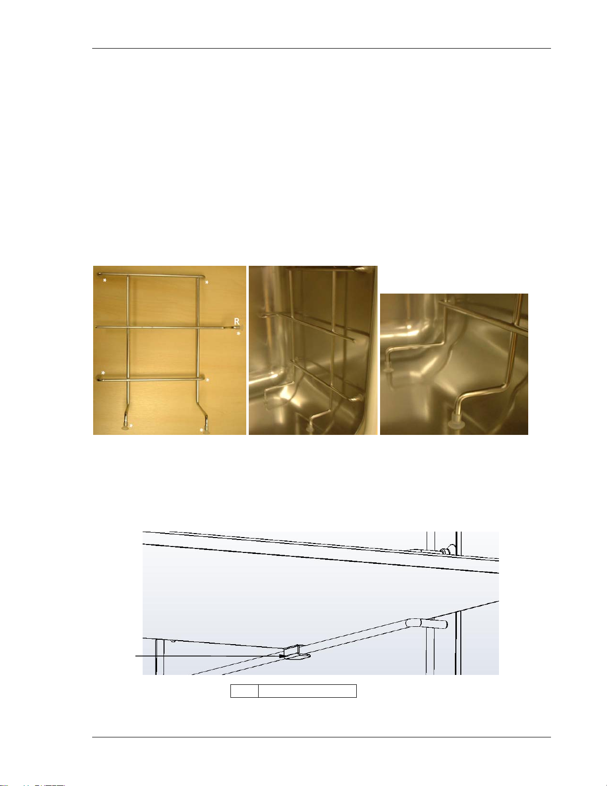
Install the shelf racks and shelves, and level the incubator:
1. Each wire shelf rack has silicone suction cups that hold the rack in place. Install the
silicone suction cups onto the wire rack supports (7 per rack, each marked with an
asterisk in Figure 1a below).
2. Note that there are lefthand and righthand racks. The suction cup marked R
(“Rear”) goes to the rear of the chamber as shown in Figure 1b below. The suction
cups will adhere to the chamber walls even if they are dry; but if you feel it is
necessary, you can dampen them with distilled water to increase adhesion.
3. Ensure the shelf racks are installed squarely in the chamber so the shelves will sit
on a level plane (see Figure 1c below).
Figure 1: Installing Shelf Racks
R
a b c
4. Install the three shelves, making sure that each shelf’s anti-tip tab is properly
inserted onto each of the wire shelf rack guides (see Figure 2 below).
Figure 2: Installing Shelves
1
1 Anti-tip tab
CO48R-0050 Galaxy R Series 48 R Personal Size CO2 Incubator User’s Guide
Page 17
17
5. Level the incubator by adjusting the feet. Place a small level on the second shelf of
the incubator. Adjust the leveling feet until the incubator is level and stable. Lock
the leveling legs in place by tightening the locking nuts on each leg.
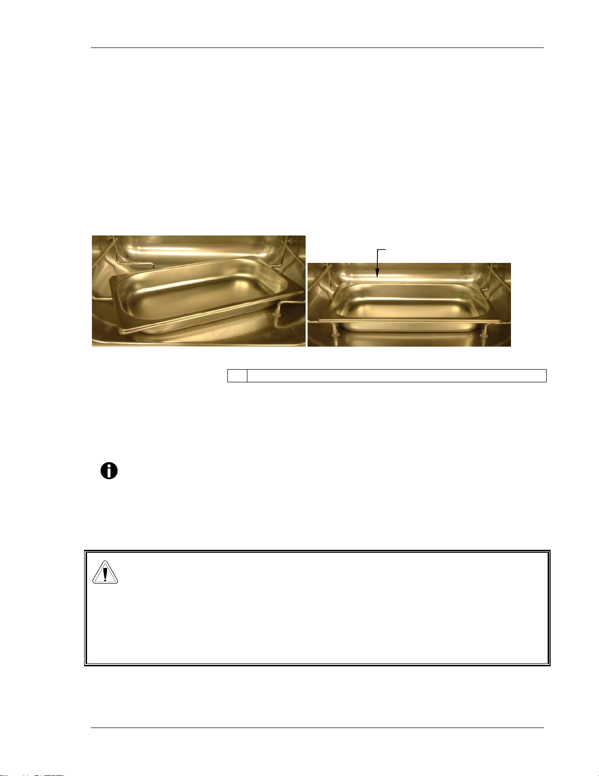
Install the humidity tray:
1. Install the humidity tray in its location beneath the lowest shelf rack position: insert
the tray diagonally (see Figure 3a), then turn the tray 45° as shown, until you can
set it in position, resting on the chamber floor, with its front and rear edges resting
just above the shelf rack supports (see Figure 3b).
Figure 3: Installing/Removing the Humidity Tray
1
a b
1 Center the tray, making sure it sits within the rack supports.
Connect the CO2 gas supply:
1. Connect the incubator to the CO2 supply using the ~1/4-inch or 6mm plastic tubing
(with installed HEPA filter) by attaching the tubing from the two-stage regulator (or
in-line regulator) to the matching CO2 inlet on the rear of the incubator.
NOTE:
It is highly recommended that an in-line regulator be used at the
incubator’s gas inlet(s).
2. Use the tubing clips provided to eliminate CO
leaks.
2
WARNING!
Slightly increased levels of CO2 may be found in and around the operating
area of the CO2 incubator. Over time, this can have adverse effects on
those exposed to such an environment. Users working in environments
with elevated levels of CO2 should take all appropriate precautions to
protect their breathing.
New Brunswick Scientific User’s Guide
Page 18
18
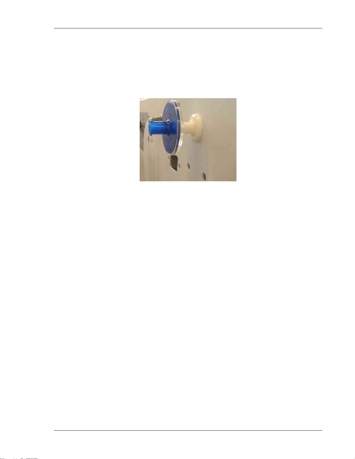
Install the HEPA AutoZero filter:
1. Press the AutoZero HEPA filter gently into the white plastic filter socket at the top
of the rear panel of the incubator (see Figure 4).
Figure 4: AutoZero HEPA Filter & Fitting
CO48R-0050 Galaxy R Series 48 R Personal Size CO2 Incubator User’s Guide
Page 19
19
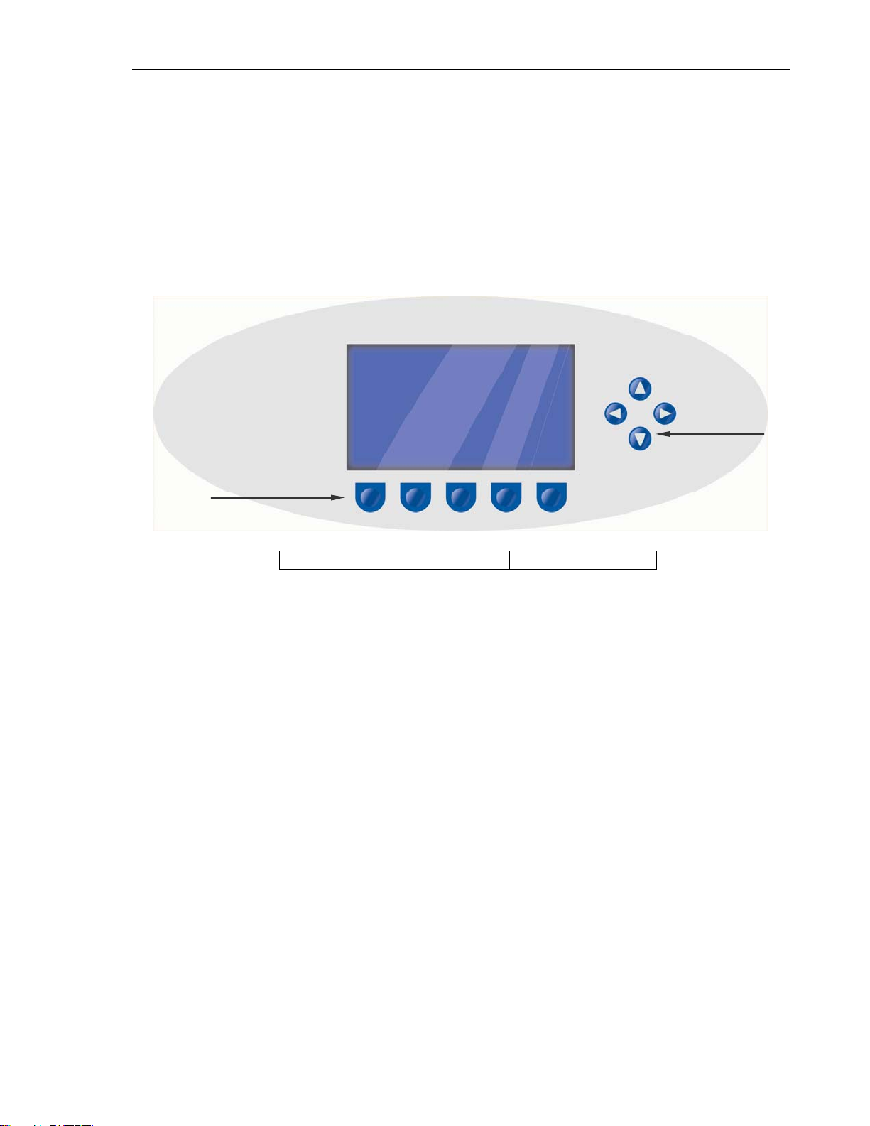
3.1 Control Panel
The control panel consists of an LCD display, five function keys & four direction keys
(see Figure 5):
2
1 Direction keys 2 Function keys
The purpose of each Function Key is identified at the bottom of the display (above each
key); the function may change from screen to screen.
The cluster of four arrowed Direction Keys will move the cursor around the screen and
adjust values.
The HELP file contains most of the information in this User Manual, together with more
detailed troubleshooting information.
33
Figure 5: Control Panel
O
PPEERRAATTIIOON
O
N
1
3.2 Preparing for Operation
1. Remove the black protective cover from the CO2 sensor (located on the back
surface of the internal chamber), and store it for use when you clean the incubator.
There is a storage holder for the cover on the back on the incubator.
2. Ensure that the white porous sensor cover remains in place.
3. Using the power cord provided, connect the incubator to a grounded power supply.
4. Switch the incubator ON using the on/off switch at the rear of the cabinet. The
display will illuminate immediately.
5. Turn on the CO2 gas supply with the pressure regulator set to 5 psi or 0.35 bar.
New Brunswick Scientific User’s Guide
Page 20

20
NOTE:
Be certain to check for leaks in the CO2 connections to avoid depleting
your CO2 gas supply. This can be accomplished using a solution of
soapy water applied to each fitting and checking for bubbles. If any
bubbles are noted, readjust the fitting.
6. The chamber setpoints are pre-programmed at 37.0°C and 5% CO
incubator on until the programmed chamber temperature and CO
. Leave the
2
concentration has
2
been reached (please see NOTE below).
NOTE:
The incubator’s CO2 valve is disabled until the incubator reaches the
temperature setpoint. After reaching the temperature setpoint, the CO
valve is activated, allowing the incubator to reach the CO
setpoint. If
2
power is interrupted to the incubator long enough for the temperature to
drop below setpoint, the CO
valve will be deactivated until setpoint is
2
again achieved. (This serves to avoid spurious CO2 readings while the
incubator is reaching its temperature setpoint)
7. Leave the incubator running for at least two hours (preferably overnight) to allow
conditions to stabilize.
2
3.3 Using the Humidity Tray & Humidity Control
If humidification is required, the humidity tray should be filled with 0.5 liters of warm
(∼ 37.0ºC) distilled water at this time.
For cell culture work, we recommend the use of copper sulphate (or a recognized
biocide) in the humidity tray. Tests have shown that, in addition to inhibiting bacterial
growth in the tray, this can reduce contamination on the chamber walls. Add one small
teaspoonful (~0.11 oz or 3.2 g) of copper sulphate each time you fill the tray with fresh
water.
For IVF and other sensitive work, we do not recommend the use of any biocide in the
humidity tray. To reduce the possibility of contamination, every 10 to 14 days, empty
the tray, clean it with a solution of 70% isopropyl alcohol and 30% distilled water, and
then refill it with 0.5 liters of warm distilled water.
To remove the humidity tray, turn it 45º to clear the shelf rack supports (see Figure 3a).
CO48R-0050 Galaxy R Series 48 R Personal Size CO2 Incubator User’s Guide
Page 21
21
CAUTION!
Never leave water in the humidity tray while the incubator is switched
off, or when a high temperature disinfection cycle is initiated, to avoid
possible damage to the CO2 sensor.
The humidity level within the chamber can be manually adjusted from ~95% to ~97%.
The controller to adjust the humidity level is found on the lower, front right side of the
instrument. The black adjustment knob can be rotated clockwise for standard (~95%)
humidity levels, and counter-clockwise to increase the humidity level.
NOTE:
The humidity tray should always be left in place, even if the incubator is
not being humidified.
3.4 Programming
3.4.1 Temperature and CO2 Level
To set the desired operating temperature and CO2 level:
1. Press the PROG function key (far left key):
2. In the PROG screen that appears, press the desired function key, TEMP or
CO2, then use the W & X direction keys to adjust the value.
NOTE:
If the incubator is supplied with the option of oxygen control, the setpoint
for the oxygen level can be selected and changed like the temperature
and CO2 setpoints.
3. When the desired setpoint is displayed, press the ENTER function key.
4. If you have made adjustments, allow the incubator to stabilize at the
setpoints before continuing. (See important NOTE on the following page.)
New Brunswick Scientific User’s Guide
Page 22

22
NOTE:
If a temperature >1°C below the actual chamber temperature is set, the
independent over-temperature system will activate. This is indicated by a
warning message on the display. When the chamber cools down, normal
operation will resume. Programming a higher temperature can also
deactivate the warning.
3.4.2 User Access Code
A USER ACCESS CODE is programmable, if required. The User Access Code
allows you to restrict access to the
settings can be changed) to authorized persons only.
To set the User Access Code:
1. In the
access code will be displayed as a series of four asterisks.
2. Use the left and right direction keys to move to each code position, and the
up and down direction keys to select a number from 0 to 9.
3. Once the number is selected, press the ENTER function key to save the code.
4. After returning to the main screen, programming access will require the
code to make any further programming changes.
To cancel the access code:
1. In the PROG screen, enter the current access code.
2. Now program 0000 as the new access code.
3. Press the ENTER function key to save the change.
4. The code is now cancelled and programming is no longer restricted.
PROG screen (accessed by pressing the PROG function key), the user
PROG, USER, and ALARM screens (where
NOTE:
If the access code has been misplaced, you will be unable to make
changes to your incubator’s settings. Contact customer service or your
service representative for instructions on how to regain access to your
incubator.
CO48R-0050 Galaxy R Series 48 R Personal Size CO2 Incubator User’s Guide
Page 23

23
3.5 Referencing CO2 Sensor with AutoZero
Prior to using the incubator, you should manually perform a CO2 AutoZero (see Section
3.6.3 for an explanation of this feature):
1. Perform a CO2 AutoZero by pressing the USER function key, selecting the
PROGRAMMABLE CO2 AUTOZERO, and pressing the START key.
2. The incubator will display a countdown as the AutoZero is running.
3. When the countdown is complete, the incubator is ready to use.
NOTE:
It may be necessary to open the door momentarily if, after performing an
AutoZero, the CO2 level is too high.
3.6 USER Settings
In the USER screen (see Figure 6), you can adjust the features called out on the screen.
There are other USER options that may be displayed on this screen if they are installed
on your incubator. See Section 7.1 for a list of options.
Figure 6: USER SETTINGS Screen
1
2
1 Use the S & T direction keys to move the cursor.
2 Use the ENTER function key to select an option.
This section explains each of the USER screen features.
New Brunswick Scientific User’s Guide
Page 24

24
3.6.1 DATE/TIME ADJUST
The date and time are factory-set and will only require adjustment if you are in
a different time zone, or when you change your clocks to Daylight Saving
Time and back again to Standard time. You may also select the style of
display for the date.
A battery back-up system ensures that the correct time/date setting is never lost.
3.6.2 AUDIO VOLUME ADJUST
The audible volume can be adjusted to your own preferences.
3.6.3 PROGRAMMABLE CO2 AUTOZERO
When you select this feature, the PROGRAM CO2 AUTOZERO screen (see Figure
7 below) allows you to program the AutoZero frequency and time, or run the
AutoZero function manually.
The AutoZero System automatically re-references the CO2 Sensor to
atmospheric CO2 in the following way:
1. A pump activates for two minutes, pumping HEPA-filtered atmosphere at
0.3 liters/minute into the sensor’s measuring chamber. This displaces the
chamber atmosphere completely from the sensor.
Figure 7: PROGRAM CO2 AUTOZERO Screen
NOTE:
This procedure does not affect the internal chamber environment. It will
not affect your cell culture as the procedure is being performed.
CO48R-0050 Galaxy R Series 48 R Personal Size CO2 Incubator User’s Guide
Page 25

25
2. At the end of the countdown, the control system adjusts the AutoZero Factor
to reference the sensor to 0.05% CO2, which is the approximate atmospheric
level.
3. The pump switches off and the chamber atmosphere diffuses back into the
sensor’s measuring chamber. This takes three minutes, after which the
normal CO2 control system takes over.
4. The result of the AutoZero (listed as A/Z on some screens) is sent to the
DATALOGGER ALARM EVENTS screen so that a record of the results will be
kept.
The frequency of AutoZeroing can be set in steps between once a day and once
every 28 days, which is the default setting. If not required, it can be disabled
(see Section 3.6.6).
The default time setting is 7:00 am. This can be altered to suit your
requirements. We do recommend that you only change the time setting shortly
before you start to use the incubator.
If the AutoZero function is to be run manually, simply press the
START function
key, within the PROGRAM CO2 AUTOZERO window.
NOTE:
The AutoZero will only occur if the temperature is at setpoint. If the
temperature is not at setpoint, the system will postpone AutoZero until
the setpoint is achieved.
3.6.4 DATALOGGER
See Section 3.7 for detailed information.
3.6.5
3.6.6 DISABLE
POWER FREQUENCY
You can adjust the power frequency to either 50 or 60Hz to match the local
electrical supply.
This feature allows you to inform the control system to ignore certain sensors if
their function is not required. The standard item on this menu is the CO2
PRESSURE SWITCH
according to the options installed on your incubator. See Section 7.1 for
available options.
To disable a feature, scroll to
the
ENTER function key.
. Additional DISABLE options appear on this screen
OFF using the W & X direction keys, then press
New Brunswick Scientific User’s Guide
Page 26

26
3.6.7 DISINFECTION (Model Option)
If the incubator is supplied with the High Temperature Disinfection option, the
menu item DISINFECTION will be displayed. This feature activates the
disinfection cycle of the incubator. The disinfection cycle heats the inner
chamber to 120oC, holds that temperature for 4 hours, then cools the chamber to
the selected temperature setpoint. All of the interior components (with the
exception of certain sensors) can be left in place during the cycle to ensure that
everything within the chamber is disinfectd prior to resumption of activity. For
a full explanation of this feature, see section 10.1.
3.7 DATALOGGER Screen
DATALOGGER Screen displays the following information:
The
Figure 8: DATALOGGER Screen
This section explains these features.
3.7.1
ALARM EVENTS
The following alarm events are recorded in the order in which they occurred,
with the most recent event displayed at the top.
Power ON / OFF
Chamber Temperature High / Low (programmed value)
CO
Level High / Low (programmed value)
2
CO2 Supply Failure
All System Alarms
CO2 AutoZero (A/Z) Adjustments
Oxygen and Relative Humidity (R/H) Alarms (where these options are
installed)
CO48R-0050 Galaxy R Series 48 R Personal Size CO2 Incubator User’s Guide
Page 27

27
The capacity is 99 events, after which the earliest event is overwritten and a
later event is added.
The date and time of each event are also recorded as shown in Figure 9 below.
Figure 9: ALARM EVENTS Screen
To scroll the screen back, press the T direction key. Press S to go back to the
first screen.
3.7.2 TEMPERATURE GRAPH + DOOR OPEN BAR CHART
When you select this from the DATALOGGER screen, the Door Open bar chart is
shows at the top of the screen to associate it with a temperature disturbance
(note the correlation in Figure 10 below). A temperature reading is recorded
every 18 seconds while the temperature is outside the specification of ± 0.1°C
and each reading is shown as a single pixel.
When the temperature has settled within specification, the recording is
compressed to one pixel representing ten 18-second readings (as long as the
temperature remains in specification). This allows up to ten hours of readings to
be displayed on one screen. When the temperature moves outside specification,
for instance if the door is opened, the graph reverts to individual 18-second
readings until temperature is within specification again.
When the data is compressed or decompressed, a light dotted line is displayed
vertically on the screen to signify that the time axis is changing from 15-minute
to 2½-hour increments or vice versa. A heavy dotted line is displayed when the
incubator is switched on.
New Brunswick Scientific User’s Guide
Page 28

28
Figure 10: TEMPERATURE GRAPH +
DOOR OPEN BAR CHART Screen
Compressing data allows memory space to be maximized. Once the memory
space has been filled, the earliest events are overwritten as they are replaced by
the latest recording. Graphical recording can be extended, however, to a
number of years if your incubator is equipped with an RS-232 port, by
connecting the port to a PC loaded with InnovaLog Software (see Section 7.2).
3.7.3 CO2 GRAPH + DOOR OPEN BAR CHART
These graphs record in a way similar to the Chamber Temperature graphs.
The specification for CO2 is ± 0.1%.
NOTE:
Both CO2 and Temperature graphs share the same time axis. If the time
axis changes to accommodate data in one graph, it will also change in the
other.
3.7.4 DIAGNOSTIC CHAMBER ELEMENT GRAPH
This graph records chamber element temperature over time to assist
troubleshooting.
3.7.5
DIAGNOSTIC DOOR GRAPH
This graph records the door’s inner surface temperature over time to assist
troubleshooting.
CO48R-0050 Galaxy R Series 48 R Personal Size CO2 Incubator User’s Guide
Page 29

29
3.7.6 DIAGNOSTIC DOOR ELEMENT GRAPH
This graph records door element temperature over time to assist troubleshooting.
3.7.7
RESTART GRAPHIC RECORD
This feature removes the current graph and begins a new one. The data cannot
be recovered once it is deleted.
3.8 CHAMBER ALARMS Menu Screen
CHAMBER ALARMS programming screen (see Figure 11 below) allows the
The
various alarm options to be selected and modified. Press the S or T direction
key to move around the options and the W or X direction key to adjust values.
The temperature and CO
High and Low Alarm setpoints automatically adjust to
2
within ± 0.5 of the temperature and CO2 setpoints. The alarm setpoints can also
be manually adjusted.
Figure 11: CHAMBER ALARMS Programming Screen
To arm the Chamber Alarms after a selectable delay:
1. Choose the option
2. Select
NO for both TEMP and CO2 (as shown in Figure 11 above)
ARM ALARMS WHEN AT SETPOINT:
3. Choose the option DELAY IN ARMING AFTER DOOR OPEN: and select the
desired delay (15 minutes in the sample screen above) to allow for
temperature and CO2 recovery after the door has been opened.
Alternatively, the alarm system can be set to rearm only after the original
temperature and CO2 setpoints have been achieved:
1. Choose the option
2. Select
New Brunswick Scientific User’s Guide
YES for both TEMP and CO2.
ARM ALARMS WHEN AT SETPOINT:
Page 30

30
3. When YES is selected for this function, the DELAY IN ARMING AFTER DOOR
OPEN
is ignored.
A DOOR OPEN ALARM: can be adjusted, choosing from seven preset durations
(45 seconds in Figure 11) to warn of an improperly closed door.
The AUDIBLE and VISUAL alarms can be adjusted from OFF to ON (which means
the alarm will be on continuously until it is acknowledged) in seven preset time
increments.
In the OFF position, any Chamber Alarms that occur will be displayed on the
screen without flashing and with the audible alarm inhibited.
Section 3.8.1, Chamber Alarm System Function, and Figure 13 explain in detail
how the Chamber Alarms operate.
3.8.1 Chamber Alarm System Function
When the incubator is switched ON, or after the temperature and CO2 levels
have been reprogrammed, the Alarm System is inactive until the setpoint values
(± 0.1) are achieved, after which the Alarm System is armed. As setpoint is
achieved, the CO2 and temperature alarms are individually armed.
If temperature and/or CO2 levels deviate more than the programmed setpoints,
the display flashes, the audible alarm sounds and a message appears on the
screen. You can acknowledge the alarm by pressing any key.
Figure 12: CHAMBER ALARM Message
After setpoints have been achieved for the first time
, when the inner door is
opened, the Alarm System is disabled; on closing the door, if selected, a
programmable alarm delay starts:
CO48R-0050 Galaxy R Series 48 R Personal Size CO2 Incubator User’s Guide
Page 31

31
If chamber conditions recover within the programmed alarm delay time, the
Alarm System is immediately re-armed. After the delay, the Alarm System
is armed and if the temperature and CO2 are outside the Alarm High & Low
settings, the alarm will be activated.
If an alarm occurs and the chamber subsequently recovers, the alarm stops
and the system is re-armed. Details of the Alarm Event are stored in the
Datalogger.
Figure 13: Chamber Alarm System Flow Chart
SWITCH ON
ARE TEMPERATURES AND CO2
LEVELS WITHIN +/- 0.1 OF SET
NO
IS TEMPERATURE OR CO2 LEVEL
MORE THAN +/- 0.5 OUTSIDE
POINT?
YES
ARM ALARMS
PROGRAMMED POINTS?
YES
PROGRAMMED
CHANGE
VALUES
NO
OPEN INNER DOOR
DISARM ALARMS
CLOSE INNER
DOOR
15 MINUTES
ALARM DELAY
TIMEOUT STARTED
15 MINUTES
ALARM DELAY
TIMEOUT
COMPLETED
VISIBLE AND AUDIBLE
ALARM - MESSAGE ON
NO
HAVE CONDITIONS
SCREEN
RECOVERED TO
WITHIN +/- 0.1?
YES
CANCEL ALARM BY
PRESSING ANY KEY
VISUAL AND AUDIBLE
ALARMS CANCELLED,
MESSAGE LEFT ON SCREEN
ALARMS
CANCELLED
CANCEL
MESSAGE BY
PRESSING ANY
KEY
New Brunswick Scientific User’s Guide
Page 32

32
If the CO2 valve is opened and no pressure is detected, an alarm occurs and a
warning message appears on the screen, alerting you to CHECK CO2 SUPPLY:
Figure 14: CHAMBER ALARM to Check CO2 Supply
As you can see in Figure 14 above, instructions are provided in the ALARM
screen to deal with the situation that triggered the alarm.
3.9 Diagnostic Menu Screen
The diagnostics screen (Figure 15 below) contains technical information
regarding the status of many of the system components. This screen is mainly
for technical service use, and can be used to troubleshoot the incubator systems
before service is scheduled. This information allows technical support to
optimize the service support required and to shorten service time.
Figure 15: DIAGNOSTICS Screen
CO48R-0050 Galaxy R Series 48 R Personal Size CO2 Incubator User’s Guide
Page 33

33
3.10 HELP MENU Screen
The HELP MENU screen (Figure 16 below) provides user selectable categories of
abbreviated information found in the user manual. All the major systems are
covered in the help menu, including help for installing the incubator. If the user
manual is misplaced, information about the CO2 incubator and its functions can
always be found on-screen.
Figure 16: HELP MENU Screen
New Brunswick Scientific User’s Guide
Page 34

34
4.1 General Notes
To ensure that chamber conditions remain as stable as possible, minimize the length of
time that the door is open. The magnetic door catches are specifically designed to make
door opening and closing as easy as possible. When you open the door, wipe off any
small drops of condensate that may have formed on the inner seal. This will avoid a
build-up of condensation.
If you are using the humidity tray for humidification, be sure to follow the indications
provided in Section 3.3.
4.2 Daily Checks
1. Check that the temperature and CO2 levels are reading within specification.
2. Check the reserve pressure in the CO2 cylinder (normally 725 psi or 50 bar when
full). The design of the incubator ensures very low consumption of CO2: during
normal working conditions, a typical large cylinder should last approximately 12
months (frequent door openings will deplete the supply more rapidly, however). If
there is a significant drop at the cylinder pressure of 725 psi or 50 bar, it means that
the cylinder is almost empty and should be replaced. Making certain that there are
no leaks at any of the connections will ensure a greater lifetime to the CO2 supply
and will help avoid accidentally running out of CO2.
3. Any spills in the chamber should be cleaned immediately to protect the stainless
steel surfaces.
4. Check the DATALOGGER screen for any alarms or events that may have occurred
overnight.
44
R
OOUUTTIINNEE
R
M
M
AAIINNTTEENNAANNCCE
E
4.3 Monthly Check
Remember that we recommend routine replacement of the water in the humidity tray,
and that you clean the tray at the same time.
1. If you are not changing the humidity tray water and cleaning the humidity tray
regularly, you should at least fill the humidity tray once a month. Do not, however,
exceed the maximum volume of 0.5 liters. Use warm water (~37.0°C) to ensure a
rapid return to optimum chamber conditions. After adding water, check that the
humidity tray is centered between the shelf rack supports.
CO48R-0050 Galaxy R Series 48 R Personal Size CO2 Incubator User’s Guide
Page 35

35
2. If required, you can take a sample of the gas inside the chamber using the CO
2
sample port, and check it using a CO2 gas analyzer. The CO2 sample port is located
at the top of the rear panel.
If you conduct a sampling, please do the following:
Turn off the CO2 gas by re-programming the setpoint for CO2 to 0.0% to prevent
CO2 from being injected into the chamber and giving a false reading.
Use a flow rate that is ≤ 0.5 liters/minute to take a sample.
Keep the door closed to minimize heat loss.
Remember to reset the CO2 setpoint to the desired level after sampling.
We recommend that you perform a CO
AutoZero prior to sampling (see Section
2
3.5).
3. We also recommend that you AutoZero the CO2 system at least once every 28 days
to ensure that CO
level is correct.
2
New Brunswick Scientific User’s Guide
Page 36

36
5.1 Cleaning
1. Routinely clean the exterior of the incubator by wiping it over with a soft cloth,
moistened with soapy water.
2. Rinse the soap from the cloth in clean water, and wipe the exterior surfaces again.
CAUTION!
Be sure to use only approved cleaning fluids and materials. Solvents,
chloride-based cleaning substances and abrasive materials, among
others, may cause permanent damage to the product surfaces. Also be
sure to wipe all surfaces dry, leaving them free from any foreign
particulates or fluids which could cause subsequent surface damage.
(See the CAUTIONs in Section 5.2).
55
C
LLEEAANNIINNGG
C
&
&
D
IISSIINNFFEECCTTIINNG
D
G
5.2 Disinfecting
The recommended disinfecting agent for use with the incubator is a solution of 70%
isopropanol (isopropyl alcohol) and 30% distilled water. Be sure to follow appropriate
safety regulations while you are using this solution:
WARNING!
y As a routine precaution, wear protective gloves.
y Be sure to adequately ventilate the work area as you are disinfecting,
to avoid the formation of potentially explosive alcohol vapors.
y Protect all electrical connections from contact with the alcohol
solution.
To best protect yourself, your incubator and your work area, follow these instructions:
1. Program 0.0% CO2 and switch off the incubator. Unplug the incubator from the
power supply.
CO48R-0050 Galaxy R Series 48 R Personal Size CO2 Incubator User’s Guide
Page 37

37
2. Dampen a clean cloth with the alcohol solution and wipe down all external surfaces,
taking care to keep the alcohol solution from coming into contact with any electrical
outlets or assemblies.
3. Remove all of the shelves, the humidity tray, the shelf racks and the inner door seal.
4. Place the black protective cover over the CO2 sensor. Also protect any additional
sensors, such as Oxygen or Humidity, with the cover(s) supplied.
CAUTION!
It is very important to ensure that no liquid is spilled onto the white porous
CO2 sensor cover at the rear of the chamber. Failure to use the protective
cover(s) could result in damage to the sensor(s) and may affect your
warranty.
5. You can clean the humidity tray by rinsing it in sterile water, wiping it down with
the alcohol solution, and then rinsing it with sterile water.
6. Wipe down the inside of the chamber with the alcohol solution, and leave it to dry
completely.
CAUTION!
Never use any of the following substances to clear the stainless steel, or
damage will result: Sodium Azide, Aqua Regia, Iodine, Ferric Chloride or
Sulphuric Acid.
7. Wipe the internal components of the chamber twice with the alcohol solution. Wipe
off excess liquid and leave it to dry completely.
8. Reassemble the inner door seal, the shelf racks and the shelves, before switching the
incubator on. Wipe the inner door seal with the alcohol solution, rinse and leave to
dry.
9. Ensure the protective cover(s) are removed from the sensor(s) and replaced in the
holder for safekeeping (protective covers must also be removed from any additional
sensors installed, such as Oxygen or Humidity).
10. Refill the humidity tray (as explained in Section 3.3). When you reinstall it, ensure
that the humidity tray is centered between the shelf rack supports.
New Brunswick Scientific User’s Guide
Page 38

38
11. Leave the incubator on for at least two hours (preferably overnight) to allow
conditions to stabilize.
12. When the incubator has stabilized, carry out an AutoZero and reprogram the desired
CO2 level. It may be necessary to open the glass door briefly if, after performing an
AutoZero, the CO2 level is too high.
5.3 High Temperature Disinfection
If your incubator is supplied with the option of high temperature disinfection, follow the
guidelines outlined in the appendix section for correctly and safely operating this option.
CO48R-0050 Galaxy R Series 48 R Personal Size CO2 Incubator User’s Guide
Page 39

39
66
Table 3: Specifications
Galaxy 48 R Incubator Specifications
Digital programming via microprocessor control on 0.1°C
increments. Measurement of chamber and door
temperature via 4 RT* matched thermistors (sensitivity
Temperature Management
Range 4°C above ambient temperature to 50°C
Control
Stability ± 0.1°C
Uniformity ± 0.2°C
CO2 Control
Range: 0.2 - 20%
Control: ± 0.1%
Stability: ± 0.2%
Uniformity: ± 0.1%
Recovery Rate: Better than 1.5% minute
Gas Connections: ~1/4-inch or 6mm tubing
Required Gas Pressure: 5 psi / 0.35 bar
Relative Humidity
Reservoir Capacity: 0.5 liters
Humidity Control: manual
Shelves
Usable Area: 875cm2 per shelf
Number of Shelves: 3 standard ; with Multiple Position Option, up to 6 shelves
Alarm Systems
Dimensions
Chamber (HxWxD): 401 x 401 x 308mm or 15.8 x 15.8 x 12.1 inches
Chamber Volume: 48 liters or 1.7 cu ft
External (HxWxD): 645 x 484 x 470mm or 25.4 x 19.1 x 18.5 inches
External, Crated (HxWxD):
Weight
0.01°C)
Adjustable independent control of door heater
“Out of Limits” temperature protection system
independent of microprocessor control.
± 0.1°C
Solid-state infrared CO
humidity. Programmable, fully automatic zeroing function.
Removable stainless steel humidity tray
Normal: 95% at 37°C
High: 97% at 37°C
Polished stainless steel, non-perforated (standard).
Two-level alarm system giving programmable audio/visual
warnings with options for remote communication. Level 1
signals system failures, level 2 is programmable and monitors
chamber conditions.
Seamless interior with removable door seal
860 x 610 x 585mm or 33.9 x 24.0 x 23.0 inches (Including
pallet)
Crated: 50 kg/110.2 lbs
Uncrated: 32kg/70.5 lbs (with standard features)
...continued...
S
PPEECCIIFFIICCAATTIIOONNS
S
sensor operating independent of
2
*RT = Resistance Temperature curve
S
New Brunswick Scientific User’s Guide
Page 40

40
Galaxy 48 R Incubator Specifications
Grounded Electrical Supply
100-120V 50/60Hz
Voltage:
or
220-240V 50/60Hz
Power:
500 watts, Standard models
700 watts, High Temperature Disinfection models
Energy to maintain 37°C: < 0.1kwh
Storage Temperature
10 - 50°C
.
CO48R-0050 Galaxy R Series 48 R Personal Size CO2 Incubator User’s Guide
Page 41

41
77
7.1 Options
Some option combinations are not possible; others may incur extra cost. Please inquire
before ordering.
Option NBS Part Number Retrofittable in
O2 Control, 1-19% CO48-XXX-0200 No
O2 Control, 1-95% P0628-5260 No
High Temperature Disinfection CO48-XXX-1000 No
Humidity Alert Package P0628-6820 No
Split Inner Door P0628-5330 No
Alarm Relay Contacts P0628-5340 Yes
Internal Power Receptacle P0628-5350 No
7.2 Available Accessories
Accessory NBS Part Number
CO2 Bottle Automatic Change-Over Instrument P0628-5000
CO2 Two Stage Regulator P0628-5010
CO2 Supply Line Filters, HEPA P0628-5020
In-Line Pressure Regulator P0628-5030
CO2 Gas Analyzer Kit P0628-5040
10 Spare CO2 Gas Analyzer Tubes P0628-5050
Air Zero Filters, HEPA (supplied in pairs) P0628-5060
Non - Perforated Shelves P0628-5070
Perforated Shelves P0628-5080
Floor Stand & Stacking Frame, for double stacking P0628-5090
Multi-position Shelf Racks (Max 6 positions) P0628-5100
O
PPTTIIOONNSS
O
&
&
A
CCCCEESSSSOORRIIEES
A
Field?
S
New Brunswick Scientific User’s Guide
Page 42

42
8.1 Options
Some option combinations are not possible, others may incur extra cost. Please inquire
before ordering.
High Temperature Disinfection CO170R-1000 No
O2 Control, 1-19% CO170R-0200 No
O2 Control, 0.1-19% P0628-5410 No
O2 Control, 1-195% P0628-5400 No
Cooling System P0628-6810 No
4 Split Inner Glass Door P0628-6780 Yes
8 Split Inner Glass Door P0628-6781 Yes
Copper Chamber P0628-5612 No
Humidity Package P0628-6820 No
BMS Relay P0628-5540 Yes
IP66 Power Receptacle P0628-5612 No
88
Options NBS Part Number
A
PPPPEENNDDIIXX
A
AA:
:
Field
Retrofitable?
O
PPTTIIOONNS
O
S
8.2 High Temperature Disinfection
The High Temperature Disinfection option is designed to heat the internal chamber to
120°C, maintain that temperature for 4 hours, and then allow the chamber to cool down
to 37°C or the programmed temperature (if different from 37°C) when normal control
takes over. The cycle is designed to disinfect all internal surfaces and components with
the exception of the Oxygen control sensor where supplied.
1. The incubator should be cleaned, disinfectd chemically and dried thoroughly before
starting the cycle (follow the instructions for Cleaning in Section 5).
2. The black protective cover must be removed before starting a cycle (the white
porous cover can remain in place). The shelves, shelf racks, humidity tray and
silicone rubber suction cups should all be in place during the cycle. If the Humidity
Tray Warning Option is fitted, ensure the sensor is placed on the bottom shelf prior
to starting the cycle. This is to protect the sensor from the direct heat at the bottom
of the incubator. The incubator MUST be clean and dry, and the humidity tray
MUST be empty, clean and dry, to continue. If it is not, permanent damage can
occur to the incubator that may void your warranty.
CO48R-0050 Galaxy R Series 48 R Personal Size CO2 Incubator User’s Guide
Page 43

43
3. To start the cycle, press the USER menu button, select DISINFECTION and press
START. The incubator will then prompt: IS CHAMBER CLEAN & DRY? Answer YES
if it is clean and dry. The cycle will start automatically. If the incubator is fitted
with a Humidity Tray Warning System, the incubator will ask two more questions:
(1) IS HUMIDITY SENSOR ON LOWER SHELF? Answer YES to continue; (2) IS
CABLE OFF BASE?
Answer YES to begin the cycle. If the incubator is fitted with
Oxygen Control, the incubator will also prompt: IS O2 SENSOR REMOVED? Ensure
the O2 sensor has been removed and answer YES to begin the cycle. Refer to
Section 8.3 for the O2 sensor removal/reinstallation procedure.
4. To cancel the cycle, press CANCEL. The incubator will cool down to the
programmed level where normal control takes over.
NOTE:
In the unlikely event of a scheduled AutoZero beginning just prior to a
disinfection cycle, the AutoZero will abort until the cycle is complete. A
user initiated AutoZero will also abort but will not resume after
completion of the disinfection cycle.
5. If the incubator door is opened during a disinfection cycle, the process will continue
as normal but will cause a failure message if the temperature falls as a result during
the heating phase and especially during the disinfection phase.
WARNING!
The door should NOT be opened during the cycle due to the hazardous
high temperatures involved. Serious burns could occur if the door is
opened during the cycle.
NOTE:
The chamber walls and CO
120 - 150°C, particularly in areas that are inaccessible to chemical
disinfection. Certain areas of the glass door and inner door seal surface
temperatures will be somewhat lower than 120°C.
6. After completion of the process, one of the following status messages will be
displayed.
If the cycle:
• was completed successfully, DISINFECTION COMPLETED OK is shown.
• was cancelled by the user,
sensor all achieve temperatures of between
2
DISINFECTION WAS ABORTED is shown.
New Brunswick Scientific User’s Guide
Page 44

44
• failed for any reason, DISINFECTION FAILED [CODE: XX]. The codes are shown
in Table 4a and described in Table 4b. If this happens, please note the failure
code and contact your service representative for advice.
Table 4a: Disinfection Failure Codes & Descriptions
Failure Code Failure Code Description
(see Table 4b below)
01
02
03
04
05
06
07
08
09
0A
0B
0C
0D
0E
0F
Z
W
W, Z
X
X, Z
W, X
W, X, Z
Y
Y, Z
W, Y
W, Y, Z
X, Y
X, Y, Z
W, X, Y
W, X, Y, Z
Table 4b: Disinfection Failure Code Explanations
Failure Code
Description
W
X
Y
Z
Temperature drop during warm-up period: indicates
the temperature fell more than 2°C during the
heating phase over a 60-second period.
Temperature drop during 4-hour period: indicates
the temperature fell below 118.0°C during the
disinfection phase.
Temperature increase during cool-down phase:
indicates the temperature rose by more than 2°C
during the cooling phase over a 60-second period.
Cancel key pressed.
Explanation
NOTE:
If the incubator power is cycled
due to a power outage, the incubator will power up as normal. This
condition will be indicated by the absence
status message (DISINFECTION COMPLETED OK).
CO48R-0050 Galaxy R Series 48 R Personal Size CO2 Incubator User’s Guide
OFF then ON during a disinfection cycle
of a completed disinfection
…continued…
Page 45

45
If the chamber temperature is above the setpoint or the element
temperature is greater than a factory-preset control point, cool-down will
be entered until these conditions are satisfied.
NOTE:
It is recommended that for the first few disinfection cycles, the AutoZero
function be run following each disinfection cycle.
8.3 High Temperature Disinfection Option with Oxygen Control
The Oxygen Sensor is an electro-chemical device that will be destroyed by the high
temperature used to disinfect the incubator if left in place. For this reason, the Oxygen
Sensor must be removed from the incubator prior to a High Temperature Disinfection
Cycle. The sensor can be accessed from the rear panel of the incubator.
Detailed removal and installation instructions are provided in Sections 8.3.1 and 8.3.2
below.
CAUTION!
The incubator should be positioned to allow access to the back for
removal of the optional Oxygen Sensor prior to starting a High
Temperature Disinfection cycle.
8.3.1 Oxygen Sensor Removal
Prior to beginning a disinfection cycle, remove the Oxygen Sensor as follows:
1. Remove the black plastic plug that covers the Oxygen Sensor located on the back of
the incubator.
2. Disconnect the sensor cable by unplugging the electrical connector (grasp the white
connector body, not the wire leads).
3. Unscrew the Oxygen Sensor by turning it counter-clockwise. If the sensor is
difficult to remove, the unthreaded end of the black plastic blanking plug can be
used as a removal tool. Never use excessive force or metal tools.
4. Store the sensor in a clean, safe place until the disinfection cycle is over.
5. The incubator is now ready to perform a disinfection cycle.
8.3.2 Oxygen Sensor Replacement
When the cool-down period of the disinfection cycle has finished, reinstall the Oxygen
Sensor as follows:
New Brunswick Scientific User’s Guide
Page 46

46
1. Using the blanking plug as a tool, reinstall the Oxygen Sensor by turning it
clockwise.
NOTE:
The O2 sensor only needs to be finger tight. Do not over-tighten, as this
will distort the Oxygen Sensor and cause it to malfunction.
2. Reconnect the sensor cable by plugging in the connector (grasp the white connector
body, not the wire leads).
3. Replace the black plastic plug that covers the Oxygen Sensor to reduce heat loss.
8.4 BMS Relay Contact Alarm Option
The BMS (Building Management System) Relay Contact Alarm allows a signal from a
central alarm system to be switched ON or OFF to indicate an alarm condition at the
incubator.
The following alarms would activate the system: over-temperature, under-temperature,
system failure, CO2 high and CO2 low.
As an integral option, the alarm can be programmed to indicate when the power fails
(perhaps due to an electrical fault) or is switched off. If the power failure warning is
active, the relay contacts will be reversed (pin 4, which is normally open, becomes
normally closed and pin 6, which is normally closed, becomes normally open). The
alarm will also respond to other types of alarm, depending on the options installed on
the incubator.
The system is connected at the rear of the incubator via a standard 6-pin DIN socket
(see Figure 17 for a detailed look). The matching plug is provided, when the option is
installed, in the accessories bag.
Figure 17: BMS Relay Contact Alarm Socket
3
2
1
1-6 See Table 5 on the following page.
CO48R-0050 Galaxy R Series 48 R Personal Size CO2 Incubator User’s Guide
6
4
5
Page 47

47
Table 5: BMS Relay Contact Alarm Socket Pin Designation
Pin Designation
1 24VDC unregulated
2 0V
3 5VDC Via 10KΩ pull-up resistor, for a logic signal to directly
4 Normally closed
5 Common
6 Normally open
*Cable length should not exceed 3 meters (9.8 ft) to comply with EMC requirements.
To power external equipment such as a remote buzzer
or light (100mA maximum current available).*
control an auxiliary control system.*
To access the relay contacts. Contact limits are 3 Amps
@ 24V DC and 3 Amps @ 34 VAC.
The default setting for the alarm system is ON. To deactivate the relay using
the incubator keypad:
1. Press USER.
2. Select BMS ALARM RELAY.
3. Select MAKE ALARM RELAY ACTIVE YES/NO.
4. Toggle to NO and then press ENTER.
The default setting for the power failure warning is ON. To make the alarm
system ignore any power outage (intentional or not):
1. Press USER.
2. Select BMS ALARM RELAY.
3. Select MAKE ALARM RELAY ACTIVE AT POWER SWITCH OFF/FAILURE
YES/NO
.
4. Toggle to NO and then press ENTER.
8.5 O2 Control (1-19%)
This oxygen control option is designed to cover the 1-19% range by adding nitrogen to
bring the level below ambient. If you have the 0.1-19% oxygen control option, skip
ahead to Section 8.6; or if you have the 1-95% oxygen control option, skip to Section
8.7.
8.5.1 Setting Up the N2 Tank
Before you set up your oxygen control, be sure you have the proper equipment
for your nitrogen supply:
• 2 cylinders of nitrogen, regulation size W
• 1 two-stage pressure regulator
• 1 Inline pressure regulator
• 6mm PVC tubing
• tubing clips
New Brunswick Scientific User’s Guide
Page 48

48
Set up the nitrogen tanks as follows:
1. Inspect them to be sure there are no leaks or other damage.
2. Check that the two-stage pressure regulator valve and the inline pressure
regulator valve are closed by trying to turn their knobs in a counterclockwise direction; the knobs should be at the stop point.
3. Place the inline pressure regulator close to the incubator.
4. Securely attach the two-stage pressure regulator to the nitrogen tank’s outlet
and to the inline pressure regulator’s inlet with tubing, securing both ends
with clips.
5. Connect the inline pressure regulator’s outlet to the incubator’s N2 inlet
located at the top middle of the incubator’s rear panel; secure both ends with
clips.
6. Proceed as indicated in Section 8.5.2.
NOTE:
To add an automatic gas cylinder changeover instrument: with the
incubator turned off, connect its inlet to the two-stage pressure
regulator’s outlet, and the changeover instrument’s outlet to the inline
pressure regulator’s inlet with tubing, securing the ends with tubing clips.
8.5.2 Setting Up Oxygen Control
1. Remove the black plastic protective cover from the hydrophobic filter cap
(making sure that the hydrophobic filter cap is not removed with it), located
in the rear wall of the incubator chamber. Retain the cover for use when you
clean the chamber.
2. Open the nitrogen gas supply from the tank. Set the N2 tank’s outlet
pressure gauge to 1.5 bar.
3. Set the nitrogen regulator to 1 bar (14.5 psi). The nitrogen will be fed into
the incubator through a HEPA filter that is already installed in the gas line.
The gas flow rate is approximately 20 liters/minute.
NOTE:
If the programmed O2 level is close to the ambient oxygen, it may be
necessary to reduce the cylinder pressure below 1 bar to stop the oxygen
level from undershooting the programmed value.
CO48R-0050 Galaxy R Series 48 R Personal Size CO2 Incubator User’s Guide
Page 49

49
4. After the incubator has been humidified and left overnight to stabilize, select
the USER menu, then select OXYGEN SENSOR-REF TO ATMOSPHERE (see
Figure 18) and follow the onscreen instructions to automatically calibrate
the oxygen sensor to atmospheric oxygen levels. The oxygen reading is
automatically adjusted to 19.7%, which is the true reading taking into
account the relative humidity level.
Figure 18: Selecting OXYGEN SENSOR-REF TO ATMOSPHERE
5. Enable the oxygen control: (a) press the USER function key, (b) select
MANUAL DISABLE (see Figure 19) using the T or S direction key , (c)
press the ENTER function key, (d) select ON for Oxygen Control using the
W or X direction key, then (e) press the ENTER function key.
Figure 19: USER SETTINGS Screen
6. Navigate to the
PROG screen to set the required Oxygen level.
7. The Alarm levels are automatically set to ± 0.5% above or below the
programmed value, but you can modify them in the ALARM screen. Rearming the alarm can be delayed until the programmed value is achieved:
select the relevant option in the ALARM screen.
New Brunswick Scientific User’s Guide
Page 50

50
NOTE:
At low oxygen levels, the CO
within the Alarm limits after the 15-minute “Delay in arming after door
opening.” This time period can be increased (in the ALARM screen) to
suit individual circumstances.
8. By controlling the Duty Cycle of the N
tailored to achieve programmed Oxygen and Carbon Dioxide levels at
approximately the same time.
8.5.3 Operating Guidelines
We recommend that you repeat the OXYGEN SENSOR-REF TO ATMOSPHERE procedure
(see Step 3 in Section 8.5.1 and further details in Section 8.5.4) once a month to ensure
that any long-term drift in sensor output will be corrected. Be sure to do it at the
chamber operating temperature.
When you are cleaning the chamber, be very careful not to wet the oxygen sensor or CO2
sensor. Never use solvents on the sensor membrane; rather, be sure to cap the hydrophobic
filter before you clean. In fact, it is good practice to replace the filter each time you clean
the incubator chamber, to avoid the possibility of filter contamination.
Under normal relative humidity conditions (95-99%), the oxygen sensor’s performance
should not be affected. If, however, liquid condenses around the sensor, gas flow may
become restricted, giving the sensor a low signal. This may occur if there is a large
liquid spill inside the chamber or if the incubator is turned off while it is fully
humidified. Should such condensation appear, normal operation can be restored by:
• removing the humidity tray,
• drying the chamber completely,
• and then running the incubator at 37°C for one hour.
This will dry out the sensor(s). The humidity tray can then be reinstalled and the
incubator can be safely re-humidified.
8.5.4 Referencing to Atmosphere
The oxygen sensor is a self-powered electrochemical cell that has a finite life dependent
on the ambient oxygen level. A typical lifespan is 1-2 years at atmospheric levels.
During the sensor’s lifespan, the signal produced will slowly degrade until it is
ultimately unusable. For this reason, we recommend that you reference the sensor to
atmospheric oxygen levels on a monthly basis.
and O2 levels may not have fully recovered
2
valve, Oxygen Control can be
2
CO48R-0050 Galaxy R Series 48 R Personal Size CO2 Incubator User’s Guide
Page 51

51
The OXYGEN SENSOR-REF TO ATMOSPHERE procedure has three possible outcomes.
The first is that the procedure was completely successful, and no further action need be
taken until the following month’s test. The second and third outcomes are presented in
detail in Sections 8.5.5 (Replace Sensor Soon) and 8.5.6 (Replace Sensor Now).
See Section 8.5.7 for instructions on removing and replacing the sensor.
8.5.5 Replace Sensor Soon
If the referencing procedure was successful but the sensor is nearing the end of
its working life, the following message will appear in the display:
O2 REFERENCE OK BUT SENSOR REQUIRES REPLACEMENT SHORTLY
PRESS ENTER TO PROCEED
When you press the ENTER function key, the message will change to this:
O2 SENSOR
THE RESULT OF THE O
SIGNAL FROM THE O
APPROACHING THE END OF ITS LIFE.
REPEAT THE REFERENCE PROCEDURE TO CONFIRM THIS RESULT.
PRESS ENTER TO PROCEED.
REFERENCE PROCESS SHOWS THAT THE
2
SENSOR HAS REDUCED INDICATING IT IS
2
Press the ENTER function key.
8.5.6 Replace Sensor Now
If the referencing procedure failed, Oxygen Control will be disabled—but the
incubator will function perfectly in all other ways—until a new sensor is
installed and corrected references to the atmosphere. The following message
will appear in the display:
O2 REFERENCE FAILED
PRESS ENTER TO PROCEED
When you press the
ENTER function key, the message will change to this:
O2 SENSOR
THE RESULT OF THE O
SIGNAL FROM THE O
ACCEPTABLE LEVEL AND HAS REACHED THE END OF ITS LIFE.
REFERENCE PROCESS SHOWS THAT THE
2
SENSOR HAS REDUCED BELOW AN
2
New Brunswick Scientific User’s Guide
Page 52

52
REPEAT THE REFERENCE PROCEDURE TO CONFIRM THIS RESULT.
PRESS NEXT TO PROCEED.
When you press the NEXT function key, the message will change to this:
O2 SENSOR
OXYGEN CONTROL HAS BEEN DISABLED AS A RESULT BUT THE
INCUBATOR IS OTHERWISE FULLY OPERATIONAL.
PRESS PREV TO VIEW PREVIOUS SCREEN.
PRESS EXIT TO EXIT.
When you press the EXIT function key, you will return to the USER screen and
normal operation.
8.5.7 Removing & Replacing O2 Sensor
To remove and replace the oxygen sensor, you will need the sensor removal tool
provided (see Figure 21 on the following page):
1. Pull the rear access cover (see Figure 20) off the rear outside wall of the
incubator to gain access to the oxygen sensor.
Figure 20: Oxygen Sensor Rear Access Cover
2. Reach inside and disconnect the sensor by unplugging the connector: be
sure to grasp the white connector body, not the wire leads!
CO48R-0050 Galaxy R Series 48 R Personal Size CO2 Incubator User’s Guide
Page 53

53
WARNING!
Never pull on the wire leads; disconnect the white connector body.
3. Using the sensor removal tool (see Figure 21), unscrew the oxygen sensor
by turning it counter-clockwise. Because the oxygen sensor contains lead,
be sure to dispose of it according to local regulations.
Figure 21: Oxygen Sensor Removal Tool
4. Using the sensor removal tool, install the new oxygen sensor by turning it
clockwise until it is finger-tight. Do not use excessive force or any metal
tool.
5. Reconnect the sensor by plugging the white connector body back in.
6. Make sure that the sensor wires are inside the metal sensor tube to protect
them from damage, then press the rear access cover snugly back in place.
7. After replacing the sensor, humidify the incubator and allow it to stabilize
overnight.
8. Calibrate the sensor with reference to the atmospheric oxygen level (see
Section 8.5.4).
8.5.8 Replacing the Filter Disc
The hydrophobic filter installed on your Oxygen Control system helps prevent
condensation from reaching the sensor (see Figure 22 on the following page).
New Brunswick Scientific User’s Guide
Page 54

54
Figure 22: Hydrophobic Filter & Holder Assembly
(exploded view)
1
4
3
2
1 Oxygen sensor holder 4 Hydrophobic filter holder
2 Oxygen sensor 5 Hydrophobic filter cap
3 Hydrophobic filter disc
5
To replace the hydrophobic filter disc (membrane), with reference to Figure 22
above:
1. Carefully pull the complete hydrophobic filter holder away from the oxygen
sensor holder on the rear wall of the chamber.
2. With a fingertip or a 10-11mm (½-inch) rod, from the rear of the filter
holder, gently push the filter membrane disc and the filter cap out of the
holder.
3. Clean and dry the filter holder and cap.
4. Wearing gloves to avoid contaminating the filter disc, gently place the new
filter membrane disc into the filter holder recess. The filter disc works in
both directions, so there is no right or wrong side.
5. Make sure the O-rings (between the cap & filter holder and between the
filter holder & oxygen sensor holder) are undamaged and securely in place.
6. Gently press the filter cap back in.
7. Press fit the filter assembly back onto the oxygen sensor holder.
CO48R-0050 Galaxy R Series 48 R Personal Size CO2 Incubator User’s Guide
Page 55

55
8.5.9 Troubleshooting the Oxygen Sensor
If the oxygen sensor fails suddenly, it is very likely that the sensor inlet
membrane has become blocked by condensation. This can be seen on the
DATALOGGER screen as a sudden drop from the programmed value to nearly
zero.
To dry the membrane:
1. Remove the hydrophobic filter holder assembly (see Figure 22) by
unscrewing it (counter-clockwise).
2. Program the incubator for a temperature of at least 37°C (or higher if you
normally operate the incubator at a higher temperature).
3. Close the door and allow the temperature to recover.
4. Reopen the door for 15 seconds to release any build-up of humidity.
5. Repeat steps 3 and 4 every 30 minutes or so, keeping an eye on the
DATALOGGER O2 Graph. The oxygen level should rather suddenly
recover after a few hours.
6. Leave the incubator for a few more hours to be sure that the sensor
membrane has thoroughly dried out.
7. Replace the hydrophobic filter disc following the instructions in Section
8.5.8.
8. Re-humidify the incubator.
9. After 2 or 3 hours, carry out an OXYGEN SENSOR-REF TO
ATMOSPHERE procedure. When the referencing has been successfully
completed, the incubator is ready for use.
8.5.10 Oxygen Control Specifications
The Oxygen Control option has the following characteristics:
Sensor Type
Zero Signal in Nitrogen
Temperature Compensation
Relative Humidity Range
Operating Temperature Range
Resolution
Expected Operating Life
Hydrophobic Filter Operating
Life
Nitrogen Input Rate
Typical Oxygen Reduction
Rates
Self-powered, diffusion-limited, electrochemical
cell with temperature compensation.
< 50 μV
± 2% of signal variation from 0-40°C
0-99%, non-condensing
-20°C to +50°C
0.01% Oxygen
1-2 years in ambient oxygen
No data available on the filter lifespan but we are
confident to expect it will last at least 6 months.
20 l/min at 1 bar (14.5 psi)
3 minutes to 16%
4 minutes to 11%
8 minutes to 6%
New Brunswick Scientific User’s Guide
Page 56

56
8.6 O2 Control (0.1-19%)
This oxygen control option uses the controlled addition of nitrogen to reduce the
oxygen level below ambient. If you have the 1-19% oxygen control option, go back to
Section 8.5; or if you have the 1-95% oxygen control option, skip ahead to Section 8.7.
8.6.1 Setting Up the N2 Tank
Before you set up your oxygen control, be sure you have the proper equipment
for your nitrogen supply:
• 2 cylinders of nitrogen, regulation size W
• 1 two-stage pressure regulator
• 1 Inline pressure regulator
• 6mm PVC tubing
• tubing clips
Set up the nitrogen tanks as follows:
1. Inspect them to be sure there are no leaks or other damage.
2. Check that the two-stage pressure regulator valve and the inline pressure
regulator valve are closed by trying to turn their knobs in a counterclockwise direction; the knobs should be at the stop point.
3. Place the inline pressure regulator close to the incubator.
4. Securely attach the two-stage pressure regulator to the nitrogen tank’s outlet
and to the inline pressure regulator’s inlet with tubing, securing both ends
with clips.
5. Connect the inline pressure regulator’s outlet to the incubator’s N2 inlet on
the right side of the equipment tray at the rear of the incubator (see Figure
7); secure both ends with clips.
6. Proceed as indicated in Section 8.6.2.
NOTE:
To add an automatic gas cylinder changeover instrument: with the
incubator turned off, connect its inlet to the two-stage pressure
regulator’s outlet, and the changeover instrument’s outlet to the inline
pressure regulator’s inlet with tubing, securing the ends with tubing clips.
8.6.2 Setting Up O
Oxygen control is tailored such that both the O2 and the CO2 levels are achieved
at approximately the same time, via control of the N
only within the range of 0.1-19% O2).
CO48R-0050 Galaxy R Series 48 R Personal Size CO2 Incubator User’s Guide
Control
2
valve’s duty cycle (but
2
Page 57

57
1. Remove the black plastic protective cover (making sure that the
hydrophobic filter cap is not removed with it) from the port inside the
chamber. Retain the cover for use when you clean the chamber.
2. Open the nitrogen gas supply from the tank and set the N2 tank’s outlet
pressure gauge to 1.5 bar.
3. Set the nitrogen regulator to 1 bar (14.5 psi). The nitrogen will be fed into
the incubator through a HEPA filter that is already installed in the gas line.
The gas flow rate is approximately 20 liters/minute.
NOTE:
If the programmed O2 level is close to the ambient oxygen, it may be
necessary to reduce the cylinder pressure below 1 bar to stop the oxygen
level from undershooting the programmed value.
NOTE:
When working at 0.1% O2, set the CO2 pressure to 0.2 bar (2.9 psi).
Be sure to humidify the incubator and leave it overnight to stabilize before
proceeding further.
To automatically calibrate the sensor to atmospheric oxygen levels, select
OXYGEN SENSOR – REF TO ATMOSPHERE in the USER menu, and then follow
the onscreen instructions.
The oxygen reading is automatically adjusted to 19.7%, which is the true
reading taking into account the Relative Humidity in the chamber.
8.6.3 Enabling or Disabling O2 Control
To enable oxygen control:
1. Select the
2. Use the direction keys to select MANUAL DISABLE.
3. Press the
Oxygen Control.
4. Press the
Program the required oxygen level in the PROG screen, following the onscreen
instructions.
To disable oxygen control, follow the pattern used to enable it, but this time
select USER, MANUAL DISABLE, ENTER, OFF and then ENTER again.
USER screen by pressing the USER function key.
ENTER function key, then use the direction keys to select ON for
ENTER function key again.
New Brunswick Scientific User’s Guide
Page 58

58
8.6.4 Alarms
The alarm levels are set automatically to ± 0.5% above and below the
programmed value, but these points can be altered in the ALARM screen. In
addition, the rearming of the alarm can be delayed until the Programmed Value
is achieved by selecting the relevant option in the ALARM screen.
For example, it is possible at low oxygen levels that the CO2 and O2 levels
might not fully recover within the Alarm Limits after the 15-minute DELAY IN
ARMING AFTER DOOR OPENING
increased in the ALARM screen to suit individual circumstances.
8.6.5 Referencing to Atmosphere
To reference the oxygen sensor to atmospheric oxygen levels, see Section 8.5.4.
8.6.6 Programming Desired O2 Level
Program the required oxygen level in the PROG screen, following the onscreen
instructions.
If you are running an O2 level programmed between 0.1-0.9%,
you should know that the control system is set to operate in the following way to
minimize N2 consumption after the glass door has been opened:
• The N2 valve is switched on continuously until the O2 level is within 0.1%
of setpoint.
• The CO2 valve is then switched on to allow the CO2 level to reach setpoint.
If the O2 level is above setpoint 15 minutes after the N2 valve has been
switched off, it is switched back on for 40 seconds and the CO
switched on for 20 seconds. The CO
reached.
• The process described above will repeat itself until the O
reached.
• The same process will also repeat if the O2 level rises above setpoint, and if
the O2 level should rise toward 0.2% above setpoint, the N2 valve will open
again continuously until the O
• The CO
AutoZero, which would normally take place after a CO2 alarm, will
2
be cancelled to avoid the introduction of additional O2 into the chamber.
For the same reason, we recommend canceling the programmed CO
AutoZero.
period has elapsed, so this time period can be
valve is
2
valve will then pulse until setpoint is
2
setpoint is
2
level returns to setpoint.
2
2
CO48R-0050 Galaxy R Series 48 R Personal Size CO2 Incubator User’s Guide
Page 59

59
8.6.7 Precautions
Under normal humidity conditions (95-99% RH), the sensor is unaffected. If
for any reason (such as a large spill inside the chamber or the incubator being
switched off while fully humidified) liquid condenses around the sensor, the
result may be restriction of gas flow and a low sensor signal. Should such
condensation appear on the chamber walls, normal operation can be easily
restored by removing the humidity tray, drying the chamber completely, and
then running the incubator at 37°C for one hour. This will dry out the sensor.
After the hour has elapsed, the humidity tray can be reinstalled and the
incubator humidified again.
8.7 O2 Control (1-95%)
This oxygen control option uses the controlled addition of oxygen to increase the level
above ambient and the controlled addition of nitrogen to reduce the oxygen level below
ambient. If you have the 1-19% oxygen control option, go back to Section 8.5; or for
the 0.1-19% oxygen control option, go back to Section 8.6.
If your incubator is operating in the 3-95% range of O2 control, only the N2 valve will
operate for setpoints below 19%; both the N2 and O2 valves will operate for setpoints
between 19 and 80%; and for setpoints above 80%, only the O2 valve will operate.
NOTE:
If you plan to maintain O2 levels of 80-95%, be sure to read Section 8.7.4.
WARNING!
High oxygen levels inside the chamber require additional safety
precautions:
Setting the oxygen to levels >24% can greatly increase the chance of fire
and explosion. Operators planning to set oxygen at 24-95% should
therefore take all appropriate precautions to minimize the risk. NBS does
not recommend using external (heat-generating) equipment inside the
chamber when oxygen conditions will be >24%.
Before opening the incubator door, make sure no flames (Bunsen
burner, etc.) are in the vicinty.
Avoid the presence of other combustible gases (hydrogen, methane,
etc.)
Ensure that all solenoid valves and pressure regulators & gauges
controlling the gas supply are grease-free for use with oxygen.
New Brunswick Scientific User’s Guide
Page 60

60
8.7.1 Setting Up the N2 Tank
Before you set up your oxygen control, be sure you have the proper equipment
for your nitrogen supply:
• 2 cylinders of nitrogen, regulation size W
• 1 two-stage pressure regulator
• 1 Inline pressure regulator
• 6mm PVC tubing
• tubing clips
Set up the nitrogen tanks as follows:
1. Inspect them to be sure there are no leaks or other damage.
2. Check that the two-stage pressure regulator valve and the inline pressure
regulator valve are closed by trying to turn their knobs in a counterclockwise direction; the knobs should be at the stop point.
3. Place the inline pressure regulator close to the incubator.
4. Securely attach the two-stage pressure regulator to the nitrogen tank’s outlet
and to the inline pressure regulator’s inlet with tubing, securing both ends
with clips.
5. Connect the inline pressure regulator’s outlet to the incubator’s N2 inlet on
the right side of the equipment tray at the rear of the incubator (see Figure
7); secure both ends with clips.
6. Proceed as indicated in Section 8.7.2.
NOTE:
To add an automatic gas cylinder changeover instrument: with the
incubator turned off, connect its inlet to the two-stage pressure
regulator’s outlet, and the changeover instrument’s outlet to the inline
pressure regulator’s inlet with tubing, securing the ends with tubing clips.
8.7.2 Setting Up O2 Control
Oxygen control is tailored such that both the O
at approximately the same time, via control of the O2 or N2 valve’s duty cycle.
1. Remove the black plastic protective cover (making sure that the
hydrophobic filter cap is not removed with it) from the port inside the
chamber. Retain the cover for use when you clean the chamber.
2. Open the nitrogen gas supply from the tank and set the N2 tank’s outlet
pressure gauge to 1.5 bar.
3. Set the nitrogen regulator to 1 bar (14.5 psi)—but be sure to read the
NOTE below. The nitrogen will be fed into the incubator through a HEPA
and the CO2 levels are achieved
2
CO48R-0050 Galaxy R Series 48 R Personal Size CO2 Incubator User’s Guide
Page 61

61
filter that is already installed in the gas line. The gas flow rate is
approximately 20 liters/minute.
4. Install the oxygen cylinder in the same manner as outlined for the nitrogen
cylinder installation in Section 8.7.1, using the incubator’s O2 inlet, of
course. For this application, you will need another two-stage pressure
regulator and another inline pressure regulator.
NOTE:
If the programmed O2 level is close to the ambient oxygen, it may be
necessary to reduce the cylinder pressure below 1 bar to stop the oxygen
level from undershooting the programmed value.
Be sure to humidify the incubator and leave it overnight to stabilize before
proceeding further.
To automatically calibrate the sensor to atmospheric oxygen levels, select
OXYGEN SENSOR – REF TO ATMOSPHERE in the USER menu, and then follow
the onscreen instructions.
The oxygen reading is automatically adjusted to 19.7%, which is the true
reading taking into account the Relative Humidity in the chamber.
8.7.3 Enabling or Disabling O2 Control
To enable oxygen control:
1. Select the USER screen by pressing the USER function key.
2. Use the direction keys to select MANUAL DISABLE.
3. Press the ENTER function key, then use the direction keys to select ON for
Oxygen Control.
4. Press the
Program the required oxygen level in the
instructions.
To disable oxygen control, follow the pattern used to enable it, but this time
select USER, MANUAL DISABLE, ENTER, OFF and then ENTER again.
ENTER function key again.
PROG screen, following the onscreen
New Brunswick Scientific User’s Guide
Page 62

62
8.7.4 Important Notes for O2 Levels >80%
If you are running the incubator with a dry chamber and no CO2, the
recommended maximum O2 level is 95%. In addition, open samples inside the
chamber can cause RH to increase, and the O2 sensor may require recalibration
to work properly in a completely dry atmosphere.
For a humidified chamber with no CO2, the recommended maximum O2 level is
92%, while for a humidified chamber with 5% CO2, we recommend no more
than 87% O2.
When the incubator is running at normal humidity level (i.e., 95% RH), there is
approximately 6% (by volume) water vapor present in the chamber. If 5% CO2
is also present, the maximum achievable level of O2—without using excessive
quantities of oxygen—is approximately 87%.
Oxygen direct from a cylinder has a dewpoint temperature of < -45°C,
corresponding to 0.06% water vapor. As it enters the incubator, therefore, its
temperature is very low and even as it is warmed, its RH level is very low. Both
of these factors affect the performance of the O2 detector. To minimize these
effects, O2 is fed continuously until it arrives at 0.4% below setpoint. To allow
the detector signal to recover and the RH level to build, there is a 3-minute
delay. If O2 is still required, it is fed in for 10 seconds, with an additional 3minute delay until setpoint is achieved.
As the humidity level rises, the O2 content in the chamber will diminish. The
use of O2 will rise considerably as the setpoint approaches the sum contents of
water wapor and CO2 in the chamber. In the short term, it is possible to achieve
higher levels of O2, but as humidity rises and O2 content is pushed down, there
will be a continuous demand for O2 and RH will remain too low. At the same
time, as O
is pumped in, the CO2 level will also diminish, causing the system to
2
add CO2, which in turn causes the O2 level to drop again.
If the O2 setpoint is too high, the incubator can consume some 2,500 liters of O2
per day—which does not include the extra oxygen consumed each time the door
is opened (about 500 liters).
8.7.5 Alarms
The alarm levels are set automatically to ± 0.5% above and below the
programmed value, but these points can be altered in the
addition, the rearming of the alarm can be delayed until the Programmed Value
is achieved by selecting the relevant option in the ALARM screen.
For example, it is possible at low oxygen levels that the CO2 and O2 levels
might not fully recover within the Alarm Limits after the 15-minute DELAY IN
ALARM screen. In
CO48R-0050 Galaxy R Series 48 R Personal Size CO2 Incubator User’s Guide
Page 63

63
ARMING AFTER DOOR OPENING period has elapsed, so this time period can be
increased in the ALARM screen to suit individual circumstances.
8.7.6 Referencing to Atmosphere
NOTE:
It is highly recommended to reference the sensor to atmospheric oxygen
at least once per month.
See Section 8.5.4 for details on this important procedure.
8.7.7 Programming Desired O2 Level
Program the required oxygen level in the PROG screen, following the onscreen
instructions.
8.7.8 Other Precautions
Under normal humidity conditions (95-99% RH), the sensor is unaffected. If
for any reason (such as a large spill inside the chamber or the incubator being
switched off while fully humidified) liquid condenses around the sensor, the
result may be restriction of gas flow and a low sensor signal. Should such
condensation appear on the chamber walls, normal operation can be easily
restored by removing the humidity tray, drying the chamber completely, and
then running the incubator at 37°C for one hour. This will dry out the sensor.
After the hour has elapsed, the humidity tray can be reinstalled and the
incubator humidified again.
For routine service checks of the sensor, see also Section 8.5.9.
8.7.9 Specifications
See Section 8.5.10.
8.8 O
Sensor Replacement
2
When the O2 sensor needs to be replaced, see Section 8.5.7 for instructions.
New Brunswick Scientific User’s Guide
Page 64

64
99
CCE
E
C
EERRTTIIFFIICCAATTIIOONN
C
CO48R-0050 Galaxy R Series 48 R Personal Size CO2 Incubator User’s Guide
Page 65

65
10.1 Index of Drawings
Figure Title Page
1 Installing Shelf Racks 16
2 Installing Shelves 16
3 Installing/Removing the Humidity Tray 17
4 AutoZero HEPA Filter & Fitting 18
5 Control Panel 19
6 USER SETTINGS Screen 23
7 PROGRAM CO2 AUTOZERO Screen 24
8 DATALOGGER Screen 26
9 ALARM EVENTS Screen 27
10 TEMPERATURE GRAPH + DOOR OPEN BAR CHART Screen 28
11 CHAMBER ALARMS Programming Screen 29
12 CHAMBER ALARM Message 30
13 Chamber Alarm System Flow Chart 31
14 CHAMBER ALARM to Check CO2 Supply 32
15 DIAGNOSTICS Screen 32
16 HELP MENU Screen 33
17 BMS Relay Contact Alarm Socket 46
18 Selecting OXYGEN SENSOR-REF TO ATMOSPHERE 49
19 USER SETTINGS Screen 49
20 Oxygen Sensor Rear Access Cover 52
21 Oxygen Sensor Removal Tool 53
22 Hydrophobic Filter & Holder Assembly (exploded view) 54
10.2 Index of Tables
Table Title Page
1 Accessories Provided 14
2 Utilities 14
3 Specifications 39
4a Disinfection Failure Codes & Descriptions 44
4b Disinfection Failure Code Explanations 44
5 BMS Relay Contract Alarm Socket Pin Designation 47
1100
D
RRAAW
D
WIINNGGSS
&
&
T
AABBLLEES
T
S
New Brunswick Scientific User’s Guide
Page 66

66
0
0.1-19% Oxygen Control, 56
1
1-19% Oxygen Control, 47
1-95% Oxygen Control, 59
A
Access Port, 12
Accessories, 41
Accessories Provided, 13
Adjustable Feet, 13
Installing the, 15
Adjusting Setpoints, 21
Alarm Delay
Programmable, 30
Alarm Events, 26
Alarm Events Screen, 27
Alarm Options, 29
Alarm Screen, 29
Alarm Socket, 46
Alarm Systems
Specifications, 39
Alarms, 12
Anti-Slip Pads
Installing the, 15
Anti-Slip Pads for Feet, 13
Audio Volume Adjust, 24
AutoZero, 12
Frequency, 35
Auto-Zero Check, 23
AutoZero System
Explanation of, 24
B
BMS Relay Contact Alarm, 46
C
CAUTION
I
1111
Symbol for, 5
CE Certification, 64
Chamber Alarm Screen, 30
Chamber Alarm System, 30
Chamber Alarm to Check CO2 Supply, 32
Checks
Daily, 34
Monthly, 34
Cleaning, 36
Clock Adjust, 24
CO2 Control
Specifications, 39
Condensation, 34
Minimizing, 12
Control Panel, 19, 21
Copyright Notice, 4
D
Datalogger, 25
Diagnostic Graphs, 28
Dimensions
Specifications, 39
Direct Heating System, 11
Direction Keys, 19
Disable Feature, 25
Disclaimer Notice, 4
Disinfecting, 36
Disinfection Failure Code Explanations, 44
Disinfection Failure Codes, 44
Drawings
Index of, 65
E
Electrical Supply
Specifications, 40
F
Filter Disc
Replacing the, 53
Function Keys, 19
NNDDEEX
I
X
CO48R-0050 Galaxy R Series 48 R Personal Size CO2 Incubator User’s Guide
Page 67

67
G
Gas Supply
Connecting the, 17
H
Harmful Substances, 37
Help Display, 19
HEPA Filter, 12
Installing the Auto-Zero, 18
HEPA Filters, 13
High Temperature Disinfection, 42
Using the, 42
with Oxygen Control, 45
Humidity Control, 12
Humidity Tray, 13
Filling the, 20
Installing the, 17
Removing the, 17
Using the, 20
Hydrophobic Filter, 53
Replacing the, 53
I
Infrared CO2 Sensor, 12
Inner Door, 12
Inner Door, Heated, 12
International Offices
List of, 2
L
Location, 14
M
Maintenance, 36
Manual Conventions, 5
N
Nitrogen Supply
Connecting the, 48, 56, 60
Nitrogen Tank
Setting up the, 47, 56, 60
NOTE
Symbol for, 5
O
Operating Notes, 34
Options
Factory-Installed, 41, 42
Retrofittable in Field, 41, 42
Over-Temperature Safety, 12
Overview, 12
Oxygen Control
0.1-19%, 56, 57
0.1-19%Alarm Impact, 58
0.1-19%On/Off, 57, 61
1-19%, 47
1-95%, 59, 61
1-95%Alarm Impact, 62
Alarms for, 49
Enabling, 49
Operating Guidelines for, 50
Setting Up, 48
Setting Up 0.1-19%, 56
Setting Up 1-95%, 60
Specifications, 55
Oxygen Sensor
Replacing the, 52
Oxygen Sensor, 45
Referencing to Atmosphere, 48, 50
Reinstalling the, 45
Removing the, 45, 52
Oxygen Sensor
Removal Tool, 52
Oxygen Sensor
Rear Access Cover, 52
Oxygen Sensor
Rear Access Cover, 53
Oxygen Sensor
Removal Tool, 53
Oxygen Sensor
Troubleshooting the, 55
Oxygen Tank
Setting up the, 61
P
Part Numbers, 41
Power Cord, 13
Power Frequency, 25
Pressure Setting, 19
New Brunswick Scientific User’s Guide
Page 68

68
Programmable CO2 AutoZero, 24
Programming, 21
R
Referencing Oxygen Sensor
0.1-19%, 58
Relative Humidity
Specifications, 39
Replace Sensor Now, 51
Replace Sensor Soon, 51
Restart Graphic Record, 29
RS232 Port, 12
S
Sealing Inner Door, 12
Sensor Cover, 13, 37
Sensor Removal Tool, 52
Service Parts, 41
Setpoints
Factory-set, 20
Setting Up Nitrogen Tank, 47, 56, 60
Setting Up Oxygen Tank, 61
Setup Concerns
Issues to Avoid, 15
Shelf Racks, 13
Shelves, 13
Specifications, 39
Specifications, 39
Oxygen Control, 55
Storage Temperature
Specifications, 40
Suction Feet, 13
T
Table of Contents, 7
Tables
Index of, 65
Temperature Graph+Door Open Bar Chart,
27
Temperature Management
Specifications, 39
U
User Access Code, 22
Lost Number, 22
Setting the, 22
USER Screen, 23
User Settings, 23
Utilities, 14
W
WARNING
Symbol for, 5
Warranty, 5
Weight
Specifications, 39
CO48R-0050 Galaxy R Series 48 R Personal Size CO2 Incubator User’s Guide
 Loading...