

Page 1

Operating manual
Draft
—
Biological Shakers Innova® 44/44R
see
on p.Fig.Tab.p
.
Op
l
erating manua
M1282-0050
New Brunswick™ Biological Shakers
Innova® 44/44R
Operating manual
Page 2

Copyright © 2013 Eppendorf AG, Germany. No part of this publication may be reproduced without the prior permission of
the copyright owner.
Eppendorf
®
and the Eppendorf logo are registered trademarks of Eppendorf AG, Germany
New Brunswick™ and the New Brunswick™ logo are trademarks of Eppendorf AG, Germany.
Innova® is a registered trademark of New Brunswick Scientific Co., Inc., USA.
Windows
®
is a registered trademark of Microsoft Corporation in the United States and other countries.
Trademarks are not marked in all cases with ™ or ® in this manual.
M1282-0050-N/022013
Page 3

Biological Shakers Innova® 44/44R — Operating manual
Table of contents
1 Table of contents
1
1 User instructions . . . . . . . . . . . . . . . . . . . . . . . . . . . . . . . . . . . . . . . . . . . . . . . . . . . . . . . . . . . . . . . . . . . . . . . . . . . . 7
1.1 Using this manual . . . . . . . . . . . . . . . . . . . . . . . . . . . . . . . . . . . . . . . . . . . . . . . . . . . . . . . . . . . . . . . . . . . . . . . 7
1.2 Danger symbols and danger levels . . . . . . . . . . . . . . . . . . . . . . . . . . . . . . . . . . . . . . . . . . . . . . . . . . . . . . . . . 7
1.2.1 Hazard symbols . . . . . . . . . . . . . . . . . . . . . . . . . . . . . . . . . . . . . . . . . . . . . . . . . . . . . . . . . . . . . . . . . 7
1.2.2 Degrees of danger . . . . . . . . . . . . . . . . . . . . . . . . . . . . . . . . . . . . . . . . . . . . . . . . . . . . . . . . . . . . . . . 7
1.3 Symbols used . . . . . . . . . . . . . . . . . . . . . . . . . . . . . . . . . . . . . . . . . . . . . . . . . . . . . . . . . . . . . . . . . . . . . . . . . . 7
2 Safety . . . . . . . . . . . . . . . . . . . . . . . . . . . . . . . . . . . . . . . . . . . . . . . . . . . . . . . . . . . . . . . . . . . . . . . . . . . . . . . . . . . . . 8
2.1 Intended use. . . . . . . . . . . . . . . . . . . . . . . . . . . . . . . . . . . . . . . . . . . . . . . . . . . . . . . . . . . . . . . . . . . . . . . . . . . 8
2.2 User profile . . . . . . . . . . . . . . . . . . . . . . . . . . . . . . . . . . . . . . . . . . . . . . . . . . . . . . . . . . . . . . . . . . . . . . . . . . . . 8
2.3 Application limits. . . . . . . . . . . . . . . . . . . . . . . . . . . . . . . . . . . . . . . . . . . . . . . . . . . . . . . . . . . . . . . . . . . . . . . . 8
2.3.1 Description of ATEX Guideline (94/9EC) . . . . . . . . . . . . . . . . . . . . . . . . . . . . . . . . . . . . . . . . . . . . . . 8
2.4 Information on product liability . . . . . . . . . . . . . . . . . . . . . . . . . . . . . . . . . . . . . . . . . . . . . . . . . . . . . . . . . . . . . 8
2.5 Warnings for intended use . . . . . . . . . . . . . . . . . . . . . . . . . . . . . . . . . . . . . . . . . . . . . . . . . . . . . . . . . . . . . . . . 8
2.5.1 Personal injury and damage to device . . . . . . . . . . . . . . . . . . . . . . . . . . . . . . . . . . . . . . . . . . . . . . . . 9
2.5.2 Incorrect handling of accessories . . . . . . . . . . . . . . . . . . . . . . . . . . . . . . . . . . . . . . . . . . . . . . . . . . . 10
3 Product description. . . . . . . . . . . . . . . . . . . . . . . . . . . . . . . . . . . . . . . . . . . . . . . . . . . . . . . . . . . . . . . . . . . . . . . . . 11
3.1 Main illustration. . . . . . . . . . . . . . . . . . . . . . . . . . . . . . . . . . . . . . . . . . . . . . . . . . . . . . . . . . . . . . . . . . . . . . . . 11
3.2 General overview . . . . . . . . . . . . . . . . . . . . . . . . . . . . . . . . . . . . . . . . . . . . . . . . . . . . . . . . . . . . . . . . . . . . . . 12
4 Inspection and unpacking of equipment. . . . . . . . . . . . . . . . . . . . . . . . . . . . . . . . . . . . . . . . . . . . . . . . . . . . . . . . 14
4.1 Inspection of boxes . . . . . . . . . . . . . . . . . . . . . . . . . . . . . . . . . . . . . . . . . . . . . . . . . . . . . . . . . . . . . . . . . . . . . 14
4.2 Packing list verification . . . . . . . . . . . . . . . . . . . . . . . . . . . . . . . . . . . . . . . . . . . . . . . . . . . . . . . . . . . . . . . . . . 14
4.3 Unpacking of equipment . . . . . . . . . . . . . . . . . . . . . . . . . . . . . . . . . . . . . . . . . . . . . . . . . . . . . . . . . . . . . . . . . 14
4.4 Out of box concerns . . . . . . . . . . . . . . . . . . . . . . . . . . . . . . . . . . . . . . . . . . . . . . . . . . . . . . . . . . . . . . . . . . . . 14
4.5 Warranty registration . . . . . . . . . . . . . . . . . . . . . . . . . . . . . . . . . . . . . . . . . . . . . . . . . . . . . . . . . . . . . . . . . . . 14
Table of contents
5 Preparing the location. . . . . . . . . . . . . . . . . . . . . . . . . . . . . . . . . . . . . . . . . . . . . . . . . . . . . . . . . . . . . . . . . . . . . . . 15
5.1 Physical location. . . . . . . . . . . . . . . . . . . . . . . . . . . . . . . . . . . . . . . . . . . . . . . . . . . . . . . . . . . . . . . . . . . . . . . 15
5.2 Environment . . . . . . . . . . . . . . . . . . . . . . . . . . . . . . . . . . . . . . . . . . . . . . . . . . . . . . . . . . . . . . . . . . . . . . . . . . 15
5.3 Electrical requirements . . . . . . . . . . . . . . . . . . . . . . . . . . . . . . . . . . . . . . . . . . . . . . . . . . . . . . . . . . . . . . . . . . 15
5.4 Space requirements . . . . . . . . . . . . . . . . . . . . . . . . . . . . . . . . . . . . . . . . . . . . . . . . . . . . . . . . . . . . . . . . . . . . 15
6 Installation . . . . . . . . . . . . . . . . . . . . . . . . . . . . . . . . . . . . . . . . . . . . . . . . . . . . . . . . . . . . . . . . . . . . . . . . . . . . . . . . 17
6.1 Tools required for installation . . . . . . . . . . . . . . . . . . . . . . . . . . . . . . . . . . . . . . . . . . . . . . . . . . . . . . . . . . . . . 17
6.2 Install the front grille . . . . . . . . . . . . . . . . . . . . . . . . . . . . . . . . . . . . . . . . . . . . . . . . . . . . . . . . . . . . . . . . . . . . 17
6.3 Level a single shaker . . . . . . . . . . . . . . . . . . . . . . . . . . . . . . . . . . . . . . . . . . . . . . . . . . . . . . . . . . . . . . . . . . . 17
6.4 Level the optional base. . . . . . . . . . . . . . . . . . . . . . . . . . . . . . . . . . . . . . . . . . . . . . . . . . . . . . . . . . . . . . . . . . 18
6.5 Mount Innova 44/44R on optional base . . . . . . . . . . . . . . . . . . . . . . . . . . . . . . . . . . . . . . . . . . . . . . . . . . . . . 18
6.6 Install the stacking kit . . . . . . . . . . . . . . . . . . . . . . . . . . . . . . . . . . . . . . . . . . . . . . . . . . . . . . . . . . . . . . . . . . . 20
6.6.1 For two 44/44R shakers . . . . . . . . . . . . . . . . . . . . . . . . . . . . . . . . . . . . . . . . . . . . . . . . . . . . . . . . . . 20
6.6.2 For an Innova 4400/4430 on an Innova 44/44R . . . . . . . . . . . . . . . . . . . . . . . . . . . . . . . . . . . . . . . . 21
6.7 Stack two Innova 44/44R shakers . . . . . . . . . . . . . . . . . . . . . . . . . . . . . . . . . . . . . . . . . . . . . . . . . . . . . . . . . 22
6.8 Stack a 4400/4430 on a 44/44R . . . . . . . . . . . . . . . . . . . . . . . . . . . . . . . . . . . . . . . . . . . . . . . . . . . . . . . . . . . 24
6.9 Stack a third shaker . . . . . . . . . . . . . . . . . . . . . . . . . . . . . . . . . . . . . . . . . . . . . . . . . . . . . . . . . . . . . . . . . . . . 24
7 Features . . . . . . . . . . . . . . . . . . . . . . . . . . . . . . . . . . . . . . . . . . . . . . . . . . . . . . . . . . . . . . . . . . . . . . . . . . . . . . . . . . 25
7.1 Controls . . . . . . . . . . . . . . . . . . . . . . . . . . . . . . . . . . . . . . . . . . . . . . . . . . . . . . . . . . . . . . . . . . . . . . . . . . . . . 25
7.2 LCD display. . . . . . . . . . . . . . . . . . . . . . . . . . . . . . . . . . . . . . . . . . . . . . . . . . . . . . . . . . . . . . . . . . . . . . . . . . . 26
3
Page 4

1
Table of contents
Biological Shakers Innova® 44/44R — Operating manual
7.3 Changing screens. . . . . . . . . . . . . . . . . . . . . . . . . . . . . . . . . . . . . . . . . . . . . . . . . . . . . . . . . . . . . . . . . . . . . . 27
7.4 Display icons. . . . . . . . . . . . . . . . . . . . . . . . . . . . . . . . . . . . . . . . . . . . . . . . . . . . . . . . . . . . . . . . . . . . . . . . . . 29
7.5 Alarms . . . . . . . . . . . . . . . . . . . . . . . . . . . . . . . . . . . . . . . . . . . . . . . . . . . . . . . . . . . . . . . . . . . . . . . . . . . . . . 30
7.5.1 Optional remote alarm. . . . . . . . . . . . . . . . . . . . . . . . . . . . . . . . . . . . . . . . . . . . . . . . . . . . . . . . . . . . 30
7.6 Glide-up door . . . . . . . . . . . . . . . . . . . . . . . . . . . . . . . . . . . . . . . . . . . . . . . . . . . . . . . . . . . . . . . . . . . . . . . . . 31
7.7 Spill pan/water reservoir . . . . . . . . . . . . . . . . . . . . . . . . . . . . . . . . . . . . . . . . . . . . . . . . . . . . . . . . . . . . . . . . . 31
7.8 Software interfaces. . . . . . . . . . . . . . . . . . . . . . . . . . . . . . . . . . . . . . . . . . . . . . . . . . . . . . . . . . . . . . . . . . . . . 31
7.9 Interior light(s). . . . . . . . . . . . . . . . . . . . . . . . . . . . . . . . . . . . . . . . . . . . . . . . . . . . . . . . . . . . . . . . . . . . . . . . . 31
7.10 Heater. . . . . . . . . . . . . . . . . . . . . . . . . . . . . . . . . . . . . . . . . . . . . . . . . . . . . . . . . . . . . . . . . . . . . . . . . . . . . . . 31
7.11 Refrigeration (44R only) . . . . . . . . . . . . . . . . . . . . . . . . . . . . . . . . . . . . . . . . . . . . . . . . . . . . . . . . . . . . . . . . . 31
7.12 Service accessibility . . . . . . . . . . . . . . . . . . . . . . . . . . . . . . . . . . . . . . . . . . . . . . . . . . . . . . . . . . . . . . . . . . . . 31
8 Getting started . . . . . . . . . . . . . . . . . . . . . . . . . . . . . . . . . . . . . . . . . . . . . . . . . . . . . . . . . . . . . . . . . . . . . . . . . . . . . 32
8.1 Platform assemblies . . . . . . . . . . . . . . . . . . . . . . . . . . . . . . . . . . . . . . . . . . . . . . . . . . . . . . . . . . . . . . . . . . . . 32
8.2 Installation of platform. . . . . . . . . . . . . . . . . . . . . . . . . . . . . . . . . . . . . . . . . . . . . . . . . . . . . . . . . . . . . . . . . . . 32
8.3 Install flask clamps . . . . . . . . . . . . . . . . . . . . . . . . . . . . . . . . . . . . . . . . . . . . . . . . . . . . . . . . . . . . . . . . . . . . . 33
8.4 Electrical connections. . . . . . . . . . . . . . . . . . . . . . . . . . . . . . . . . . . . . . . . . . . . . . . . . . . . . . . . . . . . . . . . . . . 34
8.5 Optional gassing manifold kit . . . . . . . . . . . . . . . . . . . . . . . . . . . . . . . . . . . . . . . . . . . . . . . . . . . . . . . . . . . . . 35
8.6 Optional UV germicidal lamp . . . . . . . . . . . . . . . . . . . . . . . . . . . . . . . . . . . . . . . . . . . . . . . . . . . . . . . . . . . . . 35
8.7 Optional photosynthetic lamps . . . . . . . . . . . . . . . . . . . . . . . . . . . . . . . . . . . . . . . . . . . . . . . . . . . . . . . . . . . . 35
8.8 Optional humidity monitor. . . . . . . . . . . . . . . . . . . . . . . . . . . . . . . . . . . . . . . . . . . . . . . . . . . . . . . . . . . . . . . . 35
8.9 Fill the water reservoir . . . . . . . . . . . . . . . . . . . . . . . . . . . . . . . . . . . . . . . . . . . . . . . . . . . . . . . . . . . . . . . . . . 35
8.10 Drain the water reservoir . . . . . . . . . . . . . . . . . . . . . . . . . . . . . . . . . . . . . . . . . . . . . . . . . . . . . . . . . . . . . . . . 36
9 Operation . . . . . . . . . . . . . . . . . . . . . . . . . . . . . . . . . . . . . . . . . . . . . . . . . . . . . . . . . . . . . . . . . . . . . . . . . . . . . . . . . 37
9.1 Safety precautions . . . . . . . . . . . . . . . . . . . . . . . . . . . . . . . . . . . . . . . . . . . . . . . . . . . . . . . . . . . . . . . . . . . . . 37
9.2 Open the door. . . . . . . . . . . . . . . . . . . . . . . . . . . . . . . . . . . . . . . . . . . . . . . . . . . . . . . . . . . . . . . . . . . . . . . . . 37
9.3 Start the shaker . . . . . . . . . . . . . . . . . . . . . . . . . . . . . . . . . . . . . . . . . . . . . . . . . . . . . . . . . . . . . . . . . . . . . . . 37
9.4 Using the LCD screens. . . . . . . . . . . . . . . . . . . . . . . . . . . . . . . . . . . . . . . . . . . . . . . . . . . . . . . . . . . . . . . . . . 37
9.4.1 Display screen. . . . . . . . . . . . . . . . . . . . . . . . . . . . . . . . . . . . . . . . . . . . . . . . . . . . . . . . . . . . . . . . . . 37
9.4.2 Summary screen. . . . . . . . . . . . . . . . . . . . . . . . . . . . . . . . . . . . . . . . . . . . . . . . . . . . . . . . . . . . . . . . 39
9.4.3 Setup screen. . . . . . . . . . . . . . . . . . . . . . . . . . . . . . . . . . . . . . . . . . . . . . . . . . . . . . . . . . . . . . . . . . . 40
9.4.4 Lamps screen . . . . . . . . . . . . . . . . . . . . . . . . . . . . . . . . . . . . . . . . . . . . . . . . . . . . . . . . . . . . . . . . . . 42
9.4.5 RS232 Screen. . . . . . . . . . . . . . . . . . . . . . . . . . . . . . . . . . . . . . . . . . . . . . . . . . . . . . . . . . . . . . . . . . 43
9.4.6 Calibrate screen . . . . . . . . . . . . . . . . . . . . . . . . . . . . . . . . . . . . . . . . . . . . . . . . . . . . . . . . . . . . . . . . 44
9.4.7 Programs screen. . . . . . . . . . . . . . . . . . . . . . . . . . . . . . . . . . . . . . . . . . . . . . . . . . . . . . . . . . . . . . . . 44
9.5 Program the shaker . . . . . . . . . . . . . . . . . . . . . . . . . . . . . . . . . . . . . . . . . . . . . . . . . . . . . . . . . . . . . . . . . . . . 45
9.5.1 Timer only . . . . . . . . . . . . . . . . . . . . . . . . . . . . . . . . . . . . . . . . . . . . . . . . . . . . . . . . . . . . . . . . . . . . . 45
9.5.2 Programmed steps . . . . . . . . . . . . . . . . . . . . . . . . . . . . . . . . . . . . . . . . . . . . . . . . . . . . . . . . . . . . . . 45
9.5.3 Create a program . . . . . . . . . . . . . . . . . . . . . . . . . . . . . . . . . . . . . . . . . . . . . . . . . . . . . . . . . . . . . . . 45
9.5.4 Edit a program . . . . . . . . . . . . . . . . . . . . . . . . . . . . . . . . . . . . . . . . . . . . . . . . . . . . . . . . . . . . . . . . . 48
9.5.5 Run a program . . . . . . . . . . . . . . . . . . . . . . . . . . . . . . . . . . . . . . . . . . . . . . . . . . . . . . . . . . . . . . . . . 48
9.6 Mute the audible alarm . . . . . . . . . . . . . . . . . . . . . . . . . . . . . . . . . . . . . . . . . . . . . . . . . . . . . . . . . . . . . . . . . . 49
9.7 Temperature offset calibration . . . . . . . . . . . . . . . . . . . . . . . . . . . . . . . . . . . . . . . . . . . . . . . . . . . . . . . . . . . . 49
9.7.1 Calculate the offset value . . . . . . . . . . . . . . . . . . . . . . . . . . . . . . . . . . . . . . . . . . . . . . . . . . . . . . . . . 49
9.7.2 Set the offset. . . . . . . . . . . . . . . . . . . . . . . . . . . . . . . . . . . . . . . . . . . . . . . . . . . . . . . . . . . . . . . . . . . 49
9.8 Using Calspeed . . . . . . . . . . . . . . . . . . . . . . . . . . . . . . . . . . . . . . . . . . . . . . . . . . . . . . . . . . . . . . . . . . . . . . . 50
9.9 Power interruption. . . . . . . . . . . . . . . . . . . . . . . . . . . . . . . . . . . . . . . . . . . . . . . . . . . . . . . . . . . . . . . . . . . . . . 50
9.10 Slide-out platform . . . . . . . . . . . . . . . . . . . . . . . . . . . . . . . . . . . . . . . . . . . . . . . . . . . . . . . . . . . . . . . . . . . . . . 50
10 Troubleshooting. . . . . . . . . . . . . . . . . . . . . . . . . . . . . . . . . . . . . . . . . . . . . . . . . . . . . . . . . . . . . . . . . . . . . . . . . . . . 52
10.1 General troubleshooting . . . . . . . . . . . . . . . . . . . . . . . . . . . . . . . . . . . . . . . . . . . . . . . . . . . . . . . . . . . . . . . . . 52
11 Maintenance . . . . . . . . . . . . . . . . . . . . . . . . . . . . . . . . . . . . . . . . . . . . . . . . . . . . . . . . . .
11.1 Routine maintenance . . . . . . . . . . . . . . . . . . . . . . . . . . . . . . . . . . . . . . . . . . . . . . . . . . . . . . . . . . . . . . . . . . . 55
4
. . . . . . . . . . . . . . . . . . . 55
. .
Page 5

Biological Shakers Innova® 44/44R — Operating manual
11.2 Cleaning external and internal surfaces . . . . . . . . . . . . . . . . . . . . . . . . . . . . . . . . . . . . . . . . . . . . . . . . . . . . . 55
11.3 Biohazard decontamination . . . . . . . . . . . . . . . . . . . . . . . . . . . . . . . . . . . . . . . . . . . . . . . . . . . . . . . . . . . . . . 55
1
12 Technical data . . . . . . . . . . . . . . . . . . . . . . . . . . . . . . . . . . . . . . . . . . . . . . . . . . . . . . . . . . . . . . . . . . . . . . . . . . . . . 56
12.1 Specifications . . . . . . . . . . . . . . . . . . . . . . . . . . . . . . . . . . . . . . . . . . . . . . . . . . . . . . . . . . . . . . . . . . . . . . . . . 56
13 Ordering information. . . . . . . . . . . . . . . . . . . . . . . . . . . . . . . . . . . . . . . . . . . . . . . . . . . . . . . . . . . . . . . . . . . . . . . . 58
13.1 Replacement parts . . . . . . . . . . . . . . . . . . . . . . . . . . . . . . . . . . . . . . . . . . . . . . . . . . . . . . . . . . . . . . . . . . . . . 58
13.2 Accessories . . . . . . . . . . . . . . . . . . . . . . . . . . . . . . . . . . . . . . . . . . . . . . . . . . . . . . . . . . . . . . . . . . . . . . . . . . 58
13.2.1 Slide-out platforms . . . . . . . . . . . . . . . . . . . . . . . . . . . . . . . . . . . . . . . . . . . . . . . . . . . . . . . . . . . . . . 58
13.2.2 Flask clamps for universal platforms. . . . . . . . . . . . . . . . . . . . . . . . . . . . . . . . . . . . . . . . . . . . . . . . . 61
13.2.3 Replacement clamp hardware kits . . . . . . . . . . . . . . . . . . . . . . . . . . . . . . . . . . . . . . . . . . . . . . . . . . 61
13.2.4 Test tube racks and other accessories . . . . . . . . . . . . . . . . . . . . . . . . . . . . . . . . . . . . . . . . . . . . . . . 61
13.2.5 Optional bases . . . . . . . . . . . . . . . . . . . . . . . . . . . . . . . . . . . . . . . . . . . . . . . . . . . . . . . . . . . . . . . . . 62
13.2.6 Optional stacking kit . . . . . . . . . . . . . . . . . . . . . . . . . . . . . . . . . . . . . . . . . . . . . . . . . . . . . . . . . . . . . 62
13.2.7 Optional handles . . . . . . . . . . . . . . . . . . . . . . . . . . . . . . . . . . . . . . . . . . . . . . . . . . . . . . . . . . . . . . . . 62
14 Transport, storage and disposal . . . . . . . . . . . . . . . . . . . . . . . . . . . . . . . . . . . . . . . . . . . . . . . . . . . . . . . . . . . . . . 63
14.1 Transport and storage. . . . . . . . . . . . . . . . . . . . . . . . . . . . . . . . . . . . . . . . . . . . . . . . . . . . . . . . . . . . . . . . . . . 63
14.2 Disposal . . . . . . . . . . . . . . . . . . . . . . . . . . . . . . . . . . . . . . . . . . . . . . . . . . . . . . . . . . . . . . . . . . . . . . . . . . . . . 63
15 Appendix A: Remote programming . . . . . . . . . . . . . . . . . . . . . . . . . . . . . . . . . . . . . . . . . . . . . . . . . . . . . . . . . . . . 64
15.1 Setting up with HyperTerminal . . . . . . . . . . . . . . . . . . . . . . . . . . . . . . . . . . . . . . . . . . . . . . . . . . . . . . . . . . . . 64
15.2 Overview of command sets . . . . . . . . . . . . . . . . . . . . . . . . . . . . . . . . . . . . . . . . . . . . . . . . . . . . . . . . . . . . . . 65
15.3 Index to command codes . . . . . . . . . . . . . . . . . . . . . . . . . . . . . . . . . . . . . . . . . . . . . . . . . . . . . . . . . . . . . . . . 66
15.4 Set commands . . . . . . . . . . . . . . . . . . . . . . . . . . . . . . . . . . . . . . . . . . . . . . . . . . . . . . . . . . . . . . . . . . . . . . . . 66
15.5 Profile control commands. . . . . . . . . . . . . . . . . . . . . . . . . . . . . . . . . . . . . . . . . . . . . . . . . . . . . . . . . . . . . . . . 67
15.6 Report request commands . . . . . . . . . . . . . . . . . . . . . . . . . . . . . . . . . . . . . . . . . . . . . . . . . . . . . . . . . . . . . . . 68
15.7 Set/Get date and time. . . . . . . . . . . . . . . . . . . . . . . . . . . . . . . . . . . . . . . . . . . . . . . . . . . . . . . . . . . . . . . . . . . 68
Table of contents
16 Appendix B: Certifications . . . . . . . . . . . . . . . . . . . . . . . . . . . . . . . . . . . . . . . . . . . . . . . . . . . . . . . . . . . . . . . . . . . 69
16.1 Certifications. . . . . . . . . . . . . . . . . . . . . . . . . . . . . . . . . . . . . . . . . . . . . . . . . . . . . . . . . . . . . . . . . . . . . . . . . . 69
Index . . . . . . . . . . . . . . . . . . . . . . . . . . . . . . . . . . . . . . . . . . . . . . . . . . . . . . . . . . . . . . . . . . . . . . . . . . . . . . . . . . . . . 70
5
Page 6

1
Biological Shakers Innova® 44/44R — Operating manual
Table of contents
6
Page 7

Biological Shakers Innova® 44/44R — Operating manual
1 User instructions
1 User instructions
1.1 Using this manual
Carefully read this operating manual before using the device for the first time.
Also observe the operating manual enclosed with the accessories.
The operating manual should be considered as part of the product and stored in a location
that is easily accessible.
When passing the device on to third parties, be sure to include this operating manual.
If this manual is lost, please request another one. The current version can be found on our
website www.eppendorf.com.
1.2 Danger symbols and danger levels
1.2.1 Hazard symbols
Hazard point Burns
Electric shock Material damage
1
User instructions
Explosion Heavy loads
Inhalation
1.2.2 Degrees of danger
The following degree levels are used in safety messages throughout this manual. Acquaint
yourself with each item and the potential risk if you disregard the safety message.
DANGER Will lead to severe injuries or death.
WARNING May lead to severe injuries or death.
CAUTION May lead to light to moderate injuries.
NOTICE May lead to material damage.
1.3 Symbols used
Example Meaning
You are requested to perform an action.
1.
2.
Perform these actions in the sequence described.
• List.
References useful information.
7
Page 8

2
Safety
Biological Shakers Innova® 44/44R — Operating manual
2 Safety
2Safety
2.1 Intended use
This device is exclusively intended for indoor use and for uniform movement and temperature
control of biological solutions and cultures in reaction vessels.
Lack of safety due to incorrect accessories or spare parts
Accessories and spare parts that are not recommended by Eppendorf compromise the safety,
CAUTION!
2.2 User profile
2.3 Application limits
2.3.1 Description of ATEX Guideline (94/9EC)
function and precision of the device. Eppendorf cannot be held liable or accept any liability for
damage resulting from the use of non-recommended accessories and spare parts.
Only use accessories and original spare parts recommended by Eppendorf.
The device may only be operated by trained lab personnel who have carefully read this operating
manual and are familiar with the device functions.
Explosion hazard
Do not operate the device in areas where work is completed with explosive substances.
DANGER!
Do not use this device to process any explosive or highly reactive substances.
Do not use this device to process any substances which could create an explosive
atmosphere.
Due to its design and the ambient conditions in its interior, the device is not suitable for use in
potentially explosive atmospheres.
The device may only be used in a safe environment, e.g., the open atmosphere of a ventilated
lab.
The use of substances which may contribute to a potentially explosive atmosphere is not
permitted.
The final decision regarding the risks associated with using these types of substances is the
user's responsibility.
2.4 Information on product liability
In the following cases, the designated protection of the device may be compromised.
The liability for the function of the device passes to the operator if:
• The device is not used in accordance with this operating manual.
• The device is used outside of the range of application described in the succeding chapters.
• The device is used with accessories or consumables that were not approved by Eppendorf.
• Service or maintenance is completed on the device by people who are not authorized by
Eppendorf.
• The owner has made unauthorized modifications to the device.
2.5 Warnings for intended use
Before using the device, read this operating manual and observe the following general safety
instructions.
8
Page 9

Biological Shakers Innova® 44/44R — Operating manual
2.5.1 Personal injury and damage to device
Electric shock due to damage to the device or power cable
Only switch on the device if the device and power cable are undamaged.
WARNING !
WARNING !
WARNING !
WARNING !
Only use devices that have been properly installed or repaired.
Lethal voltages inside of the device
Ensure that the housing is always closed and undamaged so the user cannot accidentally
touch the parts inside.
Do not remove the housing of the device.
Danger due to incorrect power supply
Only connect the device to voltage sources that meet the requirements on the name plate.
Only use sockets with a protective earth (PE) conductor and suitable power cable.
Health risk due to contact with infectious liquids and pathogenic bacteria
Observe the national regulations for handling these substances, the biological security level
of your laboratory, the material safety data sheets and the manufacturer's application notes.
Wear personal protective equipment (PPE).
Follow the instructions regarding hygiene, cleaning and decontamination.
For complete instructions on the handling of germs or biological material in risk group II or
higher, please refer to the "Laboratory Biosafety Manual" (source: World Health
Organization).
2
Safety
WARNING !
WARNING !
WARNING !
CAUTION!
NOTICE!
Health risk due to poisonous, radioactive or aggressive chemicals
Observe the national regulations for handling these substances as well as the material safety
data sheets and manufacturer's application notes.
Wear personal protective equipment (PPE).
Burns due to hot metal on the device and hot flasks
Only touch the device and flasks when wearing protective gloves.
Risk of crushing due to missing auxiliary aid
Lifting and transporting the shaker without suitable technical aids can result in crushing and
other injuries.
Use a hydraulic lifting platform to install and uninstall the shaker.
Risk to health due to lifting heavy loads
Only lift the device with another person or using a suitable aid.
Make sure to use a transport aid for transportation over long distances.
Damage to electronic components due to condensation
Condensation can form inside the device after the device has been moved from a cool to a
warmer environment.
Wait at least three hours before connecting it to the mains/power supply.
9
Page 10

2
Safety
Biological Shakers Innova® 44/44R — Operating manual
2.5.2 Incorrect handling of accessories
Lack of safety due to incorrect accessories or spare parts
Accessories and spare parts that are not recommended by Eppendorf compromise the safety,
CAUTION!
NOTICE!
function and precision of the device. Eppendorf cannot be held liable or accept any liability for
damage resulting from the use of non-recommended accessories and spare parts.
Only use accessories and original spare parts recommended by Eppendorf.
Danger due to damaged tubes
Small scratches and cracks can cause severe damage to the device and accessories. Liquids
may escape.
Before use, visually check all tubes for any damage.
Never use damaged tubes.
10
Page 11

Biological Shakers Innova® 44/44R — Operating manual
Incuba
t
or Shaker Series
NEW BRUNSWICK SCIENTIFIC
7321456
11 10 9 8
3 Product description
3 Product description
3.1 Main illustration
Abb. 1: Front and rear view of the In nova 44/44R
Fig. 1: Front and rear view of the Innova 44/44R
1Door
With automatic stop function
2 Door handle
3
Product description
3 Start/Stop switch
Start or stop drive
5 Push button control knob
Set or change the parameters or Start or stop drive
7 Name plate
Model number, documentation number, serial number
and electrical connection data
9 Mains power connection
Connect the power cable
11 Discharge hose
Discharge hose with clamp
4Display
Graphical user interface with display of parameters
and parameter values
6 Mains power switch
Switch device on or off
8 Base stand
Align the device horizontally.
10 RS-232 interface
Read out parameter values and control operational
functions using computer applications
11
Page 12

Biological Shakers Innova® 44/44R — Operating manual
Abb. 2: Internal view
3
1234
Fig. 2: Internal view
1 Halogen lighting 2 Drive
Eccentric drive - orbit is model-dependent.
3 Drip pan reservoir
Catch liquids and store water
4 Platform frame
Remove the platform and platform frame.
3.2 General overview
The Innova 44/44R stackable incubator and incubator refrigerated shakers are large-capacity
Product description
orbital shakers that utilize a triple eccentric counter-balanced drive mechanism. They provide
horizontal plane rotary motion in either a 2.54 cm (1 in) or a 5 cm (2 in) diameter circular orbit,
depending on the model. A Proportional/Integral (PI) microprocessor controller with
instantaneous digital feedback controls the speed over the entire speed range.
The Innova 44R provides temperature control from 20 °C below ambient (as low as 4 °C) to 80
°C, and the Innova 44 from 5 °C above ambient to 80 °C. Naturally, both these ranges depend
on relative humidity and other ambient factors, as well as the options installed in the unit.
Ambient temperature is measured at one meter from the exterior of the unit.
Erlenmeyer flasks (up to 5 liters in size) as well as a wide variety of tubes and plates can be
accommodated using the New Brunswick shaker accessories described in a later section
(see Accessories on p. 58). These are easily accessed on slide-out platforms.
The Innova 44/44R may be operated in the following ways:
• Continuously: at a set speed and temperature, until user intervention.
• In a timed mode: run at a set speed, time and temperature for a period of up to 99.9 hours,
after which the shaker automatically shuts off.
• Via the shaker’s programmable controller: run through multiple temperature and speed
changes for an extended period of time.
For more details on these various modes of operation, (see Operation on p. 37).
For safe operation, the Innova 44/44R shakers are designed with a safety switch that
automatically stops the shaker mechanism when the door is opened.
12
Page 13

Biological Shakers Innova® 44/44R — Operating manual
The Innova 44/44R is equipped with visual and/or audible alarms that alert the user to the
following conditions:
• The end of a timed run
• Deviations from speed setpoint
• Deviations from temperature setpoint
• Power failure
• Door open
• Unbalanced load
To accommodate customer needs, a wide variety of platforms can be used with the Innova 44/
44R:
• Universal platforms are the most flexible, providing hole patterns for flask clamps, test tube
racks and other accessories.
• Dedicated platforms are supplied with flask clamps attached; they are designed solely and
expressly for this purpose.
• Test tube racks, microplate holders and test tube rack holders are also available (a universal
platform is needed for all test tube racks and holders).
For further information on these accessories, (see Accessories on p. 58).
3
Product description
13
Page 14

4
Biological Shakers Innova® 44/44R — Operating manual
4 Inspection and unpacking of equipment
4 Inspection and unpacking of equipm ent
4.1 Inspection of boxes
After you receive your order from Eppendorf, inspect the boxes carefully for any damage that may
have occurred during shipping. Report any damage immediately to the carrier and to your local
Eppendorf Customer Service Department.
4.2 Packing list verification
Verify against your Eppendorf packing list that you have received all of the correct materials.
4.3 Unpacking of equipment
Risk of crushing due to missing auxiliary aid
Lifting and transporting the shaker without suitable technical aids can result in crushing and
WARNING !
other injuries.
Use a hydraulic lifting platform to install and uninstall the shaker.
To unpack your Innova 44/44R, you will need the following tools:
• Claw hammer
• Forklift or other lifting equipment to lift more than 259 kg (570 lb)
• Shears to cut 19 mm (3/4 in) wide steel strapping
• Tool to remove 7.6 cm (3 in) metal staples
Save all packing materials and this operating manual.
Inspection and unpacking of equipment
4.4 Out of box concerns
If any part of your order was damaged during shipping, is missing pieces, or fails to operate
properly, please contact your Eppendorf sales representative.
4.5 Warranty registration
Please contact your Eppendorf Regional Sales Office.
14
Page 15

Biological Shakers Innova® 44/44R — Operating manual
5 Preparing the location
5 Preparing the location
5
5.1 Physical location
It is essential that the instrument be situated in an area where there is sufficient space for the
shaker and platform to clear walls and potential obstructions during operation. The surface on
which the unit is placed must be smooth, level, and able to support the shaker under full load
operating conditions.
Risk of crushing due to missing auxiliary aid
Lifting and transporting the shaker without suitable technical aids can result in crushing and
WARNING !
other injuries.
Use a hydraulic lifting platform to install and uninstall the shaker.
5.2 Environment
The shaker is designed to operate optimally in the following ambient conditions:
• 10 °C to 35 °C
• 20 % to 80 % Relative Humidity (non-condensing)
5.3 Electrical requirements
The Innova 44/44R can be equipped to run on:
• 100 Volts, 50 Hz, 1500 VA maximum
• 100 Volts, 60 Hz, 1500 VA maximum
• 120 Volts, 60 Hz, 1500 VA maximum
• 230 Volts, 50 Hz, 1500 VA maximum
Check your shaker’s Electrical Specification Plate (located on the back of the unit) to be sure the
electrical requirements of your unit match the output of your electric supply. If they do not match,
contact your Eppendorf representative.
Preparing the location
5.4 Space requirements
Allow at least 10 cm (4 in) around the shaker for proper ventilation and for access to Power
Switch and RS-232 port accessibility on the right side. Be sure to keep the power plug and power
outlet easily accessible to facilitate unplugging the unit, as needed.
15
Page 16

Biological Shakers Innova® 44/44R — Operating manual
Incuba
t
or Sha
ker Se
ries
Incubator Sha ker Se ries
NEW B
R
UN
S
WI
C
K SCIENTIFIC
NEW B
R
UN
S
WI
C
K SCIENTIFIC
1
2
3
4
5
5
Abb. 3: Innova 44/44R Front View Two Shakers Stacked on 12 in Base
Preparing the location
Fig. 3: Innova 44/44R Front View Two Shakers Stacked on 12 in Base
1 Width: 135 cm (53 in) 2 Depth: 84 cm (33 in) including front panel
protrusions
3 Medium Base Height: 30.5 cm (12 in) 4 Height: 66 cm (26 in) without feet
5 Height: 66 cm (26 in) without feet; Note: open door
adds 53 cm (21 in)
Be sure to allow at least 10 cm (4 in) around shaker for ventilation, access to power cord (rear
Hint!
Hint!
panel), and access to power switch and RS-232 port (right side).
If you are stacking three shakers, use a 10 cm (4 in) base.
16
Page 17

Biological Shakers Innova® 44/44R — Operating manual
1
2
2
6 Installation
6 Installation
Risk of crushing due to missing auxiliary aid
Lifting and transporting the shaker without suitable technical aids can result in crushing and
WARNING !
Hint!
6.1 Tools required for installation
other injuries.
Use a hydraulic lifting platform to install and uninstall the shaker.
Feet are used on the shaker ONLY when a single unit is operated without a base. At all other
times (with two or three shakers stacked, or when a base is added), all feet must be removed.
To install the Innova 44/44R on an optional base and/or to stack Innova 44/44R units, the
following tools will be needed:
• Number 2 Phillips head screwdriver
• Blade screwdriver
• 3 mm (1/8 in) Allen key
• 3/8 in Allen key (provided)
• Level, >25.4 cm (10 in)
• Two adjustable wrenches or 7/16 in socket wrench
• Forklift or other lifting equipment able to lift more than 259 kg (570 lb)
• Metal leveling shims (provided in stacking kit)
• Optional: set of screw-in lifting handles, for small lifts of short duration (adding leveling shims,
for example) or for minor location adjustments
• Optional: stacking kit(s)
6
Installation
6.2 Install the front grille
1. Remove and discard the plastic retaining clip that holds the drain hose in place for shipping.
2. Temporarily remove the thumbscrews (with their washers) installed at the bottom of each side
panel, in the corner closest to the front of the shaker.
3. Hold the front grille in place (see Fig. 4 on p. 17) and reinstall the thumbscrews (and
Abb. 4: Install the Front Grille
Fig. 4: Install the Front Grille
1 Front Grille 2 Thumbscrews and Washers
washers).
6.3 Level a single shaker
These instructions are for a single shaker without an added base.
Make sure that the shaker is placed on a level surface and that all four feet are solidly on the
surface. If the shaker is not level, adjust the feet as needed to achieve leveling:
17
Page 18

Biological Shakers Innova® 44/44R — Operating manual
1. Immobilize the top locknut against the unit with one wrench whenever you adjust the foot, to
Abb. 5: Adjustable Foot (as shipped)
keep the threaded stud from falling out (see Fig. 5 on p. 18).
6
Installation
1
2
3.65 cm
3
4
Fig. 5: Adjustable Foot (as shipped)
1Bottom of Unit 2Locknut
3Flats for Wrench 4Foot
2. With a second wrench against the flats of the threaded stud, just above the foot, rotate
clockwise to lower the foot or counter-clockwise to raise the foot.
3. Place a level on the top of the unit. If necessary, make further adjustments by repeating all
steps until the unit is level.
4. After installing a platform (see Getting started on p. 32), fully load the shaker and do a test run
at normal speed (see Operation on p. 37). Make additional leveling adjustments if necessary.
The maximum shaker lowering adjustment is 12.7 mm (1/2 in). The shaker cannot be raised
Hint!
above the height at which it was shipped. If more adjustment is required, you will need to add
metal shims.
6.4 Level the optional base
Place the base on a sturdy (capable of bearing the weight of the combined base shakers and
shaker contents), level surface, making sure that all four corners are solidly on the surface. If the
base is not level, place metal shims as needed under the base until it is level.
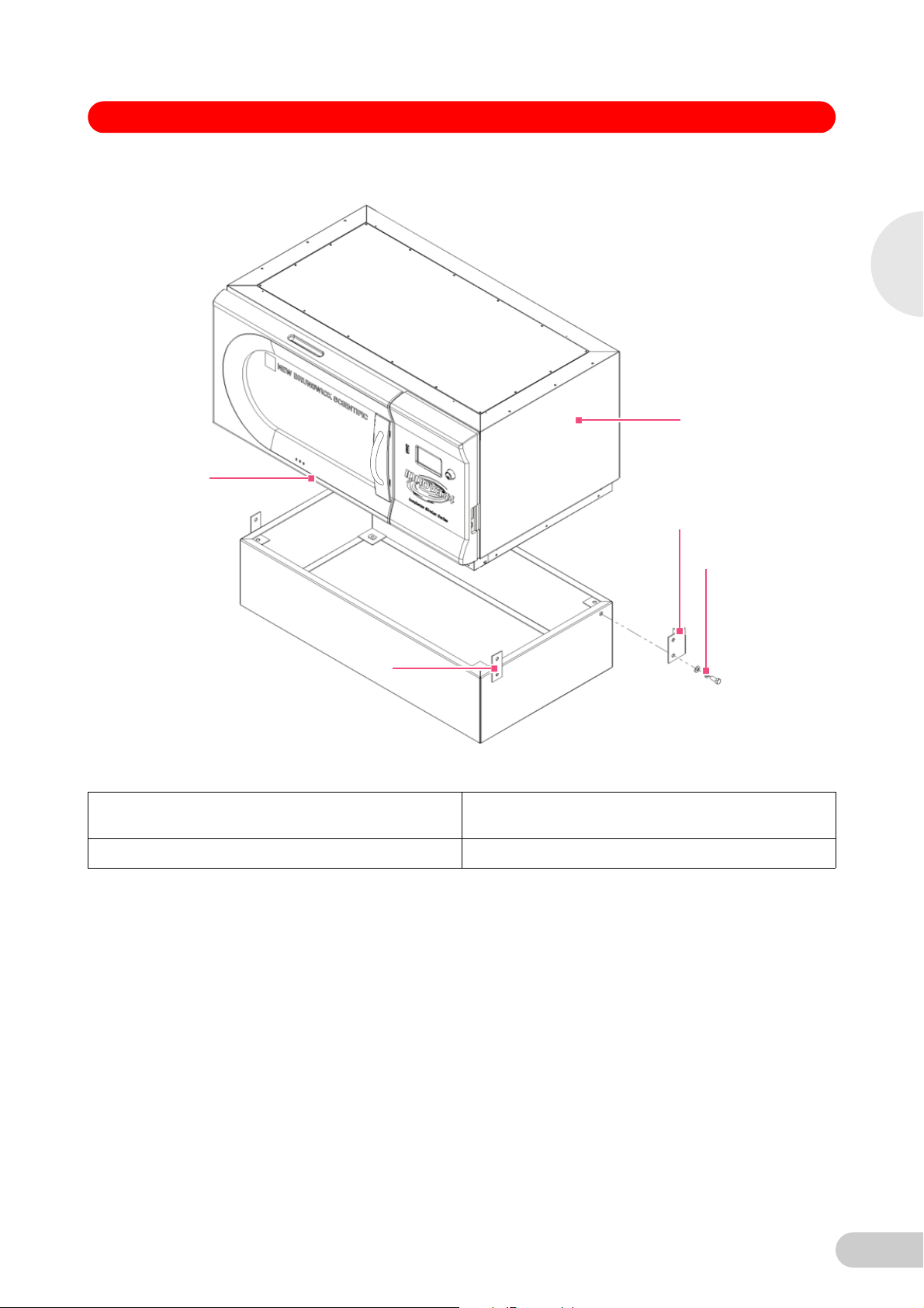
6.5 Mount Innova 44/44R on optional base
1. Using a forklift or lifter, raise the Innova 44/44R so that its back end is tilted toward the rear of
the base.
2. Remove all four feet from the bottom of the shaker. They will not be needed for stacking, but
you may want to keep them for future use.
3. With two assistants guiding the shaker from opposite sides, lower the unit onto the base, back
end first. Slowly and gently remove the forklift or lifter, lowering the front of the unit onto the
base by hand.
4. Remove the set screws from the bottom sides of the shaker that correspond to the mounting
holes for the rear corner braces (see Fig. 6 on p. 19).
18
Page 19
Biological Shakers Innova® 44/44R — Operating manual
1
2
2
3
4
Abb. 6: Mount Shaker on Base
6
Installation
Fig. 6: Mount Shaker on Base
1 Innova 44/44R 2 Remove 1/2 – 13 Set Screws from holes that match
corner braces on both sides of unit.
3 1/2 – 13 x 1 1/4 in screw 4 Note: Feet removed
5. Using the 1/2 – 13 x 1 1/4 in screws, lock washers and washers provided, mount the rear
braces on the base. Do not fully tighten the screws yet.
6. Mount the rear of the Innova 44/44R to the corner braces on the base, using the 1/2 – 13 x 1
1/4 in screws, lock washers and washers provided. Do not fully tighten the screws yet.
7. Mount the front corner braces to the base using two sets of the 1/2 – 13 x 1 1/4 in screws,
lock washers and washers provided. Do not fully tighten the screws yet.
8. With the remaining 1/2 – 13 x 1 1/4 in screws, lockwashers and washers, attach the front
corner braces to the unit.
9. Tighten all screws equally. With the corner braces securely in place, the shaker mounted on
its base will look as shown (see Fig. 7 on p. 20):
19
Page 20

6
Installation
Biological Shakers Innova® 44/44R — Operating manual
Abb. 7: Shaker Installed on Base
Fig. 7: Shaker Installed on Base
10. Make sure the shaker is level; add metal shims under the base as needed to level the unit.
Shims are provided with the stacking kit.
11. After installing a platform (see Getting started on p. 32), fully load the shaker and do a test run
at normal speed (see Start the shaker on p. 37). Make additional leveling adjustments if
necessary.
6.6 Install the stacking kit
To stack two Innova 44/44R shakers, (see For two 44/44R shakers on p. 20). To stack an Innova
4400/4300 on an Innova 44/44R, (see For an Innova 4400/4430 on an Innova 44/44R on p. 21).
6.6.1 For two 44/44R shakers
1. Remove all feet from the units (put them aside for possible future use).
2. If you do not plan to use an optional base, skip to Step 3. If you are using one, level the base
(see Level the optional base on p. 18), then mount the bottom unit on the base (see Mount
Innova 44/44R on optional base on p. 18). If you are stacking three units, use a 4 in base.
3. With reference to the figure below (see Fig. 8 on p. 21), remove the set screws from the top of
the bottom unit, on the two side edges, and remove the set screws (from the sides of the unit
to be stacked) that correspond to the mounting brackets.
20
Page 21

Biological Shakers Innova® 44/44R — Operating manual
1
2
3
4
Abb. 8: Install Innova 44/44R Stac king Kit
6
Installation
Fig. 8: Install Innova 44/44R Stacking Kit
1 Innova 44/44R 2 Remove 1/4 – 20 Set Screws before installing
stacking kit.
3 Remove set screws 4 Six sets of 1/4 – 20 x 3/4 in screws, lockwashers
and washers on each side.
4. Using the screws and washers provided, attach the stacking kit mounting brackets to the top
of the bottom unit. Secure the brackets in place as shown (see Fig. 8 on p. 21).
6.6.2 For an Innova 4400/4430 on an Innova 44/44R
1. Remove all feet from the units (put them aside for possible future use).
2. If you do not plan to use an optional base, skip to Step 3. If you are using one, level the base
(see Level the optional base on p. 18), then mount the bottom unit on the base as explained
in Section above (see Mount Innova 44/44R on optional base on p. 18). If you are stacking
three units, use a 4 in base.
3. With reference to the figure below (see Fig. 9 on p. 22), remove the screws installed at the top
of the bottom unit, on the two side edges.
21
Page 22

1
2
3
4
5
6
Installation
Biological Shakers Innova® 44/44R — Operating manual
Abb. 9: Install 4400/4430 to 44/4 4R Stacking Kit
Fig. 9: Install 4400/4430 to 44/44R Stacking Kit
1 Innova 4400/4430 2 Install right bracket with three 1/4 – 20 x 3/4 in
flathead socket screws, with two drops of Loctite
on the threads.
3 Remove screws before installing mounting
bracket.
5 Install left bracket with two sets of 10 – 32 x 1/2 in
screws, lockwashers and washers and three sets
of 1/4 – 20 x 3/4 in screws, lockwashers and
washers. Allow some play until top unit is secure
against right bracket, then tighten.
4. Use the countersunk flathead screws provided, with two drops of Loctite on their threads, to
attach the righthand (facing the door) mounting bracket to the top of the unit installed on the
base. Secure the bracket in place.
5. Use the other screws and washers provided to attach the lefthand mounting bracket to the top
of the unit installed on the base. Loosely tighten these screws, to allow some play.
6.7 Stack two Innova 44/44R shakers
1. Using a forklift or lifter, raise the Innova 44/44R to be stacked so that its back end is tilted
toward the rear of the mounting brackets.
2. Remove the feet from the unit. They will not be needed for stacking, but you may want to keep
them for future use.
4 Optional Base
22
Page 23

Biological Shakers Innova® 44/44R — Operating manual
Incuba
t
or Sha
ker Se
ries
Incubator Sha ker Se ries
NEW B
R
UN
S
WI
C
K SCIENTIFIC
NEW B
R
UN
S
WI
C
K SCIENTIFIC
3. With two assistants guiding the unit from opposite sides, lower the shaker onto the mounting
brackets, back end first. Slowly and gently remove the forklift or lifter, lowering the front of the
unit onto the mounting brackets by hand.
4. As shown (see Fig. 10 on p. 23), secure the bottom of the upper shaker to the mounting
brackets (already fastened to the shaker below) with the screws, lock washers and washers
provided.
Abb. 10: Stacked Sha kers
6
Installation
Fig. 10: Stacked Shakers
5. Make sure the shakers are level; add metal shims under the bottom unit (or base) if needed.
6. After installing a platform (see Getting started on p. 32), fully load the shaker and do a test run
If you are stacking a third shaker, (see Stack a third shaker on p. 24).
at normal speed (see Start the shaker on p. 37). Make additional leveling adjustments if
necessary.
23
Page 24

6
Installation
Biological Shakers Innova® 44/44R — Operating manual
6.8 Stack a 4400/4430 on a 44/44R
1. Using a forklift or lifter, raise the Innova 4400/4430 to be stacked so that its back end is tilted
toward the rear of the mounting brackets.
2. Remove the feet from the unit. They will not be needed for stacking, but you may want to keep
them for future use.
3. With two assistants guiding the unit from opposite sides, lower the shaker onto the mounting
brackets, back end first. Slowly and gently remove the forklift or lifter, lowering the front of the
unit onto the mounting brackets by hand and making sure it is tight against the righthand
mounting bracket.
4. As indicated (see Fig. 9 on p. 22), secure the bottom of the upper shaker to the mounting
brackets with the screws, lockwashers and washers provided. Be sure to tighten the right side
first, then secure the left side.
5. Make sure the shakers are level; add metal shims under the base if needed.
6.9 Stack a third shaker
Equipment damage
When stacking three shakers, do not use a base taller than 10.5 cm (4 in).
CAUTION!
When stacking three shakers, all shaker loads must be balanced. These shakers operate
best at maximum speed with a load of 15.5 ( ± 1.4) kg or 34 (± 3) lb, which includes all
platforms, clamps, and filled glassware.
For three stacked 2 in stroke shakers, maximum operating speed must be limited to 250 rpm.
To stack a third shaker, repeat the appropriate procedures provided above to install the stacking
kit, to stack the shaker, and to level the entire assembly.
24
Page 25

Biological Shakers Innova® 44/44R — Operating manual
1
2
3
7Features
7Features
7.1 Controls
Abb. 11: Front Pane l (detail)
Fig. 11: Front Panel (detail)
1 Control Knob 2 Display
3 Start/Stop Switch (for shaking)
7
Features
• START/STOP SWITCH: This switch is used to start or stop the shaker. It will also activate the
timer when a timed run is desired. If the unit is stopped and restarted, the timer automatically
returns to the beginning of a run.
• CONTROL KNOB: This knob is multifunctional. It is used to change screens and to select
and change operating conditions.
• RS-232 PORT: For details (see Software interfaces on p. 31).
• POWER SWITCH: This rocker switch is a circuit breaker that turns power on and off to the
entire Innova 44/44R.
In addition to the Power Switch, the Power Cord is also used to conduct power or to break the
Hint!
power circuit to the shaker. Whenever power to the shaker may be a hazard (during cleaning,
maintenance or service work), be sure to disconnect the power cord from the electrical outlet.
25
Page 26

1
2
3
4
7
Biological Shakers Innova® 44/44R — Operating manual
Abb. 12: Contr ol Panel (Right Side)
Features
Fig. 12: Control Panel (Right Side)
1 Power Switch 2 RS-232 Port
3 Front of Shaker 4 Control Knob
7.2 LCD display
When the unit is powered up, using the Power Switch located on the lower right side of the
machine (see Fig. 12 on p. 26), the initial display screen will remain for a short time while the
system boots up. Then the main screen, called DISP for Display, appears (see Fig. 13 on p. 27).
This screen will indicate the same parameters that were in effect when the power was turned off.
26
Page 27

Biological Shakers Innova® 44/44R — Operating manual
ºC 23
RPM 120
DISP We 13 : 44
1
1
2
3
4
5
6
7
8
9
9
10
Abb. 13: Display Scr een
7
Features
Fig. 13: Display Screen
1 Actual Parameter values 2 Day and 24-Hour Time
3 Program Running 4 Heater On
5 Door Open 6 Parameters Locked
7 Audible Alarm Muted 8 Screen Name
9 Parameters 10 Temperature Offset
• For an explanation of the icons on the display screen, (see Display icons on p. 29).
• Turning the Control Knob will highlight functions and/or values that can be changed.
• Whenever you turn the Control Knob, the chamber light will go on (see Interior light(s) on
p. 31).
For more information on working in the Display Screen, (see Using the LCD screens on p. 37).
7.3 Changing screens
You can change screens displayed by highlighting the screen name field in the lower left corner,
pressing the Control Knob in until it clicks, rotating the Knob left or right (which also makes
clicking sounds) to the desired screen and clicking the Control Knob in again. The table below
describes the various screens:
27
Page 28

Biological Shakers Innova® 44/44R — Operating manual
Tab. 1: Screens
Screen Name Meaning Features/Modes
7
Features
DISP Display
SUMM Summary
SET Set-Up
LAMP Lamps
COMM Communication (RS-232)
CAL Calibration
PROG Program Allows user to set up 1 – 4 programs, each with 1 – 15 steps.
1
See table below, Display Screen Parameters; 2 Optional; 3 Not installed
Shows two user-selectable parameters1 and actual values.
Shows all parameters1, setpoints and actual values.
Set day of week, set time, enable or mute alarm, lock or unlock
operating parameters
Internal chamber light: ON (always on); OFF (always off); AUTO
(default mode), light goes on and stays on when door is open,
shuts off 15 seconds after door is closed, and goes on for 15
seconds when Control Knob is moved. Photosynthetic lights
2
: ON, OFF, NONE3, UV Light (UV)2: ON, OFF, NONE3
(GRO)
SET: set baud rate OFF disables RS-232 MONITOR: PC
commands shaker to read setpoints and actual values on a
schedule determined by PC software. Parameters are unlocked
and can be changed by program or manually. SLAVE: PC controls
shaker and logs data. TALK: Shaker sends setpoint and actual
data to PC at one-minute intervals.
Allows user to enter a temperature offset. Allows user to calibrate
speed.
28
Page 29

Biological Shakers Innova® 44/44R — Operating manual
Tab. 2: Display Screen Parameters
Parameter Name Meaning
RPM Shaking speed, in revolutions/minute
°C Chamber temperature, in degrees Celsius
HRS Programmed time remaining, in hours
%RH
UV
GRO
1
1
1
1
Optional
Relative Humidity, in percent.
Status of Ultraviolet germicidal lamp
Status of Photosynthetic growth lamps
7
7.4 Display icons
Features
There are six icons that help identify operating conditions (see table below, Display Icons). Five
of these icons are located at the bottom of the display, and they are visible, when applicable, in
any screen you are viewing, except the Program subscreens. The sixth appears, when
applicable, next to °C whenever the temperature is onscreen.
29
Page 30

Biological Shakers Innova® 44/44R — Operating manual
Tab. 3: Display Icons
Icon Explanation
This icon appears when audible alarms are muted.
This icon appears when the possibility to make manual or programmed
parameter changes is disabled (locked). This is controlled by settings on the
SET screen (see Setup screen on p. 40).
7
Features
7.5 Alarms
Indication Description
POWER
TEMP
RPM
This icon appears when the shaker door is open.
This icon appears when the Heater is on (see Heater on p. 31).
This icon appears when a user-defined Program is running (see Program
the shaker on p. 45).
This icon appears to the right of °C if the Temperature Offset feature is being
used (see Temperature offset calibration on p. 49).
If an alarm condition exists, the field in the lower right corner will alternate the Day and Time with
characters indicating the nature of the alarm condition, accompanied by an audible alarm (unless
muted) (see Table below):
The temperature deviates more than ±1 °C from setpoint after achieving control
temperature range. After door is opened, alarm will be disabled for 5 minutes
while chamber recovers to setpoint.
The speed deviates more than ±5 RPM from setpoint after achieving operating
speed setpoint. After door is opened, alarm will be disabled for 5 minutes while
chamber recovers to setpoint.
Indicates unit is powering up (both at normal power-up and after power
interruption); will flash until the Control Knob is moved.
HRS Indicates when timed run is completed.
TILT
7.5.1 Optional remote alarm
30
Indicates an unbalanced shaking condition. After load is evenly distributed and/or
shaker is leveled, restart by pressing START/STOP.
The Innova 44/44R can be equipped with a factory-installed remote alarm component (part
number M1320-8029). When it is hooked up to your relay and receiving equipment, this device
will send notification of an alarm condition to the remote location you choose.
Page 31

Biological Shakers Innova® 44/44R — Operating manual
7.6 Glide-up door
The Innova 44/44R is equipped with a space-saving glide-up door.
When the door opens, the following will happen:
• Heater turns off
• Shaker stops
• Interior light goes on and, when it is in AUTO mode, will remain on for 15 seconds after the
door is closed
• UV germicidal lamp (if so equipped) turns off
• Photosynthetic lights (if so equipped) turn off.
7.7 Spill pan/water reservoir
The Innova 44/44R is equipped with a spill pan to protect the drive mechanism in the case of
accidental spills and/or broken glassware. This pan can also be used as a water reservoir to
humidify the chamber and to reduce evaporation. An optional factory-installed humidity monitor is
also available.
7.8 Software interfaces
The RS-232 port is located below the Power Switch on the right side of the control panel
(see Fig. 12 on p. 26). It can be used to interface a PC to the shaker for control of operating
conditions or data logging applications (see Appendix A: Remote programming on p. 64).
The customer is responsible for securing the proper driver to interface with the RS-232.
7
Features
7.9 Interior light(s)
When the LAMP screen is in its default AUTO mode, the interior (“chamber”) light is activated for
15 seconds whenever you turn the Control Knob. It will automatically shut off after 15 seconds of
Control Knob inactivity.
The chamber light will also go on when the door is open.
In addition, you can set the chamber light to be continuously ON or OFF by selecting either mode
in the LAMP screen.
There are two additional light options for refrigerated units only: interior photosynthetic growth
lamps (see Optional photosynthetic lamps on p. 35) and a UV germicidal lamp located outside
the chamber but in the airflow path (see Optional UV germicidal lamp on p. 35).
7.10 Heater
The chamber temperature is sensed by a 1000 ohm platinum RTD. The heater is controlled using
pulse width modulation on a 2.5 s duty cycle. This cycle time is fast enough to prevent noticeable
changes in air temperature due to the cycling.
Whenever the heater is on, the Heater On icon will appear in the display. The heater
automatically stops running when the door is opened.
7.11 Refrigeration (44R only)
The refrigeration system in the Innova 44R is a fixed-capacity system carefully designed to
maintain the setpoint, to balance pressure within the system, and to prevent freezing on the
evaporator surface.
When the shaker is powered up, there is a four-minute time delay prior to compressor start-up.
7.12 Service accessibility
In the unlikely event that your Innova 44/44R should need service, all electronic boards,
refrigeration and heating components are mounted on a pull-out drawer mechanism which is
easily accessed, by an authorized service technician, from the front of the shaker.
31
Page 32

Biological Shakers Innova® 44/44R — Operating manual
8 Getting started
8 Getting started
8.1 Platform assemblies
The Innova 44/44R can be used with a variety of Eppendorf platforms that will accept a wide
range of clamps for flasks, test tubes, etc. A platform, which is required for operation, is a
separate item, not included with the shaker assembly. For details on available platforms and
platform accessories, (see Accessories on p. 58).
8.2 Installation of platform
In transit, there are two small plastic straps on the side of the bearing housing to secure the
Hint!
slide-out mechanism and two small plastic straps that immobilize the bearing housing; all straps
must be removed.
8
Getting started
Hint!
Abb. 14: Install Sub platform
When you cut the bearing housing straps, be particularly careful not to cut the wiring that is in
close proximity to the straps.
Prior to use, a subplatform and platform must be installed on the unit. The shaker is shipped with
four Allen head platform screws installed in the bearing housing, see Figure below which also
shows the subplatform that you must install (see Fig. 14 on p. 32).
1
2
3
Fig. 14: Install Subplatform
1 Platform Screws 2 Subplatform
3Bearing Housing
1. Remove the Allen head platform screws, setting them aside.
2. Place the subplatform onto the bearing housing, taking care to orient it as shown (see Fig. 14
on p. 32), with the notches and the lever toward the front of the shaker, lever facing up.
3. Align the subplatform holes with the tapped holes in the bearing housing, then secure the
subplatform with the Allen head platform screws you previously removed.
To install the slide-out platform you have purchased:
32
Page 33

Biological Shakers Innova® 44/44R — Operating manual
1
2
3
3
1. With reference to figure below (see Fig. 15 on p. 33), place the platform on the subplatform,
making sure the two slots in the back of the platform are inserted under the subplatform’s
blocks in the back, and the slide-out tray handles are at the front edge, facing up.
Steps 2 – 4 are called out in figure below (see Fig. 15 on p. 33):
Abb. 15: Install Slide-Out Platform
8
Getting started
Fig. 15: Install Slide-Out Platform
1 Rotate subplatform cam lever 180 °
counterclockwise (away from you), until it points
to the right. This locks the platform in place.
3 Push both slide-out tray handles away from you
until the platform hits its stops at the back of the
chamber.
2 Simultaneously push both side cam levers up
(away from you and toward the back of the
chamber).
8.3 Install flask clamps
Flask clamps purchased for use with universal platforms (see Flask clamps for universal
platforms on p. 61) require installation. Clamps are installed by securing the base of the clamp to
the platform with the correct type and number of screws. All clamps are shipped complete with
hardware.
Clamps for 2, 2.8 and 4 liter flasks are shipped with an additional girdle to keep the flasks in
place. The girdle is an assembly of springs and sections of rubber tubing. One girdle is already in
place on the clamp, the other is packed separately. To install these double girdle clamps:
1. Place the clamp on the platform, aligning its mounting holes with holes on the platform.
Secure the clamp in place using the flat Phillips head screws provided (# S2116-3051, 10 –
24 x 5/16 in). Use figure below (see Fig. 17 on p. 34) to help you identify the proper screws,
as three different types of screws are shipped with the clamps.
2. With the first girdle in place, as delivered, on the upper part of the clamp body (see Fig. 16 on
p. 34), insert an empty flask into the clamp.
3. After making sure the sections of tubing are located between the clamp legs, roll the first
girdle down the legs of the clamp as far as it can go. The tubing sections will rest against the
platform, and the springs will be under the clamp base.
33
Page 34

8
Biological Shakers Innova® 44/44R — Operating manual
4. Place the second girdle around the upper portion of clamp body (just as the first girdle was
initially). Make sure that its spring sections rest against the clamp legs, while its rubber tubing
sections sit against the flask, in between the clamp legs.
Abb. 16: Double Girdle Clamp Installation
5
1
4
2
3
Fig. 16: Double Girdle Clamp Installation
Getting started
Abb. 17: Clamp Fastener
Fig. 17: Clamp Fastener
8.4 Electrical connections
1 Upper Girdle with Girdle Tubes 2 Clamp Body (Legs and Base)
3 Lower Girdle with Girdle Tubes 4 Platform
5 Clamp Mounting Holes (5)
The upper girdle secures the flask within the clamp, and the bottom girdle keeps the flask from
Hint!
spinning.
Before making electrical connections, verify that the power source voltage matches the voltage
on the electrical specification plate and that the ON/OFF switch is in the OFF position. The
electrical specification plate is located on the rear panel of the unit near the power connector.
Connect the power cord to the power connector, then connect the other end to a suitable,
grounded receptacle. Make sure there is enough clearance to disconnect the plug whenever
necessary.
34
Page 35

Biological Shakers Innova® 44/44R — Operating manual
Abb. 18: Rear Panel
3
2
Fig. 18: Rear Panel
1 Adjustable Foot 2 Air Intake Vents (Do not block)
3Power Connector
1
8
8.5 Optional gassing manifold kit
This option is factory-installed. The manifold delivers gas into the chamber and ultimately into the
flasks themselves via twelve ports. You may elect to use splitters after the manifold to increase
the number of ports for your application.
8.6 Optional UV germicidal lamp
Personnel injury and equipment damage!
Never try to operate the UV Germicidal Lamp while the shaker door is open.
WARNING !
This option, a germicidal ultraviolet lamp, is placed inside the Service Drawer, outside the
chamber to help reduce the risk of contamination. The lamp is identified on the display screen as
UV.
The UV germicidal lamp is factory-installed and available on refrigerated units only.
8.7 Optional photosynthetic lamps
This factory-installed option (for refrigerated units only) provides nine photosynthetic growth
lamps inside the chamber. They can be turned on and off manually, by the easily set
programmable timer, or by computer. These lamps are identified on the display screen as GRO.
The replacement bulb part number is P0300-0221.
The recommended operating temperature when using this option is 15 °C – 37 °C.
The maximum operating temperature when using photosynthetic lamps is 70 °C.
Getting started
8.8 Optional humidity monitor
This optional factory-installed accessory allows you to monitor actual humidity levels in the
chamber throughout your run. With humidity monitor, the maximum temperature is 60 °C.
8.9 Fill the water reservoir
If you choose to use the spill pan/reservoir as a water reservoir to reduce evaporation:
1. Temporarily remove the four thumbscrews (with their washers) that secure the front grille in
place (Fig. 19 on p. 36).
35
Page 36

1
2
8
Biological Shakers Innova® 44/44R — Operating manual
Abb. 19: Front Grille
Getting started
Fig. 19: Front Grille
8.10 Drain the water reservoir
1 Front Grille 2 Drain Hose - extends through this cutout
2. Check the drain hose to be sure it is clamped tightly.
3. Replace the grille and secure it with the four thumbscrews and the washers that you
previously removed.
Never pour water directly under the subplatform. Pour water very slowly into the shallow area
Hint!
beyond the edge of the adapter plate, to protect the bearing housing.
4. Accessing the pan/reservoir from the left, the right or in front of the subplatform, slowly fill the
reservoir with no more than 3 liters of distilled water.
To drain water from the water reservoir/spill pan:
1. Temporarily remove the four thumbscrews that secure the front grille (see Fig. 19 on p. 36).
2. Disengage the drain hose, direct it to a container or drain, then unclamp it, allowing the water
to gravity drain.
3. Reclamp the hose, tuck it back in place, and replace the grille, securing it with the
thumbscrews you previously removed.
The spill pan/water reservoir drain is located in the front, on the left, under the slide-out tray.
Hint!
Hint!
Keep it clamped even if there is no water in the pan.
36
The drain hose should be tightly clamped when it is not being used for draining the reservoir.
Page 37

Biological Shakers Innova® 44/44R — Operating manual
9 Operation
9 Operation
9.1 Safety precautions
Before operating the shaker, verify that anyone involved with its operation has been instructed in
both general safety practices for laboratories and specific safety practices for this apparatus.
• The user is also responsible for following local guidelines for handling hazardous waste and
biohazardous materials that may be generated from the use of this equipment.
• If service should be required on a unit that is going to be returned to an Eppendorf facility, it
must be completely decontaminated and cleaned prior to its return, and a Returned Material
Safety Sheet must be filled out to certify that you have complied.
• It is the responsibility of the user to carry out appropriate decontamination procedures if
hazardous material is spilled on or inside the equipment. Before using any cleaning or
decontamination method other than those suggested by the manufacturer, users should
check with Eppendorf that the proposed method would not damage the equipment.
Personnel injury and equipment damage!
This equipment is not explosion-proof and should never be used with flammable substances
WARNING !
or used to grow organisms that produce flammable by-products.
Equipment damage!
To prevent damage to the shaker and its contents, never run the shaker without a platform.
CAUTION!
9.2 Open the door
Open the door by firmly pulling the handle straight out to release the latching mechanism. You
can now manually move the door up to the open position, or down to the closed position (make
sure it latches closed).
9.3 Start the shaker
To initially start the shaker, close the door and turn the power switch (located on the righthand
side of the control panel) to the ON position. The display will come on (first showing only New
Brunswick Scientific, then briefly displaying the model number, 44 or 44R, and the stroke, 1 inch
or 2 inch, and then quickly moving into the Display screen), and the audible alarm will sound. To
mute it, (see Mute the audible alarm on p. 49).
When the shaker begins to operate, the LCD display will track the speed as it accelerates to the
last entered setpoint. The shaking action may be started or stopped by pressing the Start/Stop
button on the front panel.
The shaker will not operate if the door is open. This is indicated by the “door open” symbol
Hint!
appearing in the bottom line of the display (see Fig. 13 on p. 27).
9.4 Using the LCD screens
9
Operation
9.4.1 Display screen
When you turn the power on, this is the first screen to appear after the company title screen. The
default display parameters are temperature (°C) and shaking speed (RPM).
You can change the displayed parameters. To replace a parameter:
1. Using the Control Knob, highlight the parameter that you wish to replace. For this example,
we will replace RPM (see Fig. 20 on p. 38).
37
Page 38

Biological Shakers Innova® 44/44R — Operating manual
ºC 23
RPM 120
DISP We 13:44
ºC 23
HRS
0.0
DISP We 13:44
Abb. 20: Chang ing Display Parameter
Fig. 20: Changing Display Parameter
2. Click the Control Knob in. RPM will flash.
3. Turn the Knob until the desired parameter appears in the highlighted field. For this example,
we will select HRS.
Abb. 21: Changed Display Parameter
4. Click the Knob in to set and save the parameter (see Fig. 21 on p. 38).
9
Operation
Fig. 21: Changed Display Parameter
If you highlight an item, change it, but do not save your selection, after a few seconds the screen
Hint!
Hint!
will revert to its previous setting.
“UV” (UV Germicidal lamp) and “GRO” (photosynthetic growth lamps) will appear in this screen
with the word “NONE” if your shaker is not equipped with these optional features.
You can also use this screen to verify a setpoint, even though the values displayed here are
actual (current) values. To view a setpoint:
1. Use the Control Knob to highlight the value (in this example, we will view the temperature
setpoint, so we will highlight the current °C, which is 23).
2. Click the Knob in to display the current setpoint, which will flash.
At this point you can modify the setpoint or click the Knob in again to return to the normal display,
which will be the actual temperature.
To modify a setpoint in this screen:
1. Use the Control Knob to highlight the current value (we will continue to use the temperature
as our example, so we will select 23).
2. Click the Knob in to display the current setpoint (in this example, 38.5 (see Fig. 22 on p. 39),
which will flash.
38
Page 39

Biological Shakers Innova® 44/44R — Operating manual
ºC 38.5
RPM 120
DISP We 13:44
Abb. 22: Changing Setpoint
Fig. 22: Changing Setpoint
3. Turn or spin the Knob to reset the setpoint (in this example, turn the Knob left to decrease the
setpoint to 37.0).
If you turn the Control Knob slowly, one click left or right will change the setpoint by an increment
Hint!
of one tenth of a degree Celsius (0.1 °C). If you spin the Knob quickly, the value will change by
larger increments.
4. Click the Knob in to set and save this new setpoint.
9
Hint!
9.4.2 Summary screen
If you highlight an item, change it, but do not save your selection, after a few seconds the screen
will revert to its previous setting.
5. The display will automatically return to the actual value.
To move out of this screen and into the next:
1. Use the Control Knob to highlight DISP, then click the Knob in.
DISP begins to flash.
2. Turn the Knob to the right until the next screen, Summary (SUMM), appears. If you turn too
far and enter another screen, just turn the Knob back to the left to recapture the SUMM
screen.
3. Click the Knob in to select the screen and to work in it.
In this screen (see Fig. 23 on p. 40), you can see both the current ACTUAL readings and the
SET points for shaking speed (RPM), chamber temperature (°C), elapsed time in a programmed
run (HRS) and, if you are using the optional Humidity Monitor, the percentage of relative humidity
(%RH).
Operation
39
Page 40

PARAM ACTUAL SET
RPM 100 100
ºC 45.1 45.0
HRS 0.0 0.0
%RH 50.0 N/A
SUMM Th 16:18
9
Biological Shakers Innova® 44/44R — Operating manual
Abb. 23: Summar y Screen
Fig. 23: Summary Screen
The current day (Su, Mo, Tu, We, Th, Fr or Sa) and time always remains visible in the lower
Hint!
Operation
righthand corner.
The only elements you can modify in this screen are setpoints. To change setpoints in this
screen:
1. Turn the Knob until the desired setpoint is highlighted, then click the Knob in.
The setpoint will begin to flash.
2. Turn the Knob to the right to increase the number, or to the left to decrease it. One click left or
right will increase the setpoint by an increment of one (one whole unit or one tenth unit,
depending on the parameter). Move the Knob more rapidly (you can spin it) to change the
value by larger increments.
3. Click the Knob in to set and save the new value.
If you highlight an item, change it, but do not save your selection, after a few seconds the screen
Hint!
9.4.3 Setup screen
will revert to its previous setting.
4. Repeat the above steps to change any or all of the other setpoints.
To move out of this screen and into the next:
1. Use the Control Knob to highlight SUMM, then click the Knob in.
SUMM begins to flash.
2. Turn the Knob to the right until the next screen, Setup (SET), appears. If you turn too far and
enter another screen, just turn the Knob back to the left to recapture the SET screen.
3. Click the Knob in to select the screen and to work in it.
Here you can set the day of the week and the time (on a 24-hour clock). This screen also allows
you to lock all of your settings from further changes, and to mute or enable the audible alarm.
40
Page 41

Biological Shakers Innova® 44/44R — Operating manual
SETUP
Day : Thu
Hour/Min : 16:19
Lock : Off
Mute : Off
SET Th 16:19
Abb. 24: Setup Scree n
Fig. 24: Setup Screen
To change the day:
1. Turn the Knob to highlight the day (Thu in the sample screen above), then click inward once.
The day will flash.
2. Turn the knob left or right to select the day of choice: Sun, Mon, Tue, Wed, Thu, Fri or Sat.
3. Click the knob in to set and save your choice.
9
If you highlight an item, change it, but do not save your selection, after a few seconds the screen
Hint!
Hint!
will revert to its previous setting.
To change the time (Hour/Min):
1. Turn the knob to highlight the time (16:19 in the sample screen above), then click inward
once.
The time will flash.
2. Turn the knob left or right to change the time. Left moves backward, right moves forward in
time. One click right or left changes by one minute; spin the knob quickly to move more
rapidly.
3. Click the knob once inward to set and save your choice.
To lock the settings:
1. Turn the knob to highlight Lock, then click inward once.
The current status (Off in the sample screen above) will flash.
2. Turn the knob in either direction; the only other choice is On. Click once inward to select and
save On, or continue turning to return to Off.
When you set Lock to On, a padlock icon (see Display icons on p. 29) will appear at the bottom
of the screen. This icon will remain on display through all main display screens until you turn the
locking function off.
To mute the audible alarm:
1. Turn the knob to highlight Mute, then click inward once.
The current status (Off in the sample screen above) will flash.
Operation
2. Turn the knob in either direction; the only other choice is On. Click once inward to select and
save On, or continue turning to return to Off.
When you set Mute to On, the crossed-out speaker icon will appear at the bottom of the screen.
Hint!
This icon will remain on display through all screens until you turn the muting function off.
41
Page 42

Biological Shakers Innova® 44/44R — Operating manual
LAMPS
Chamber : Auto
UV Decont : Off
Growth : Off
LAMP Th 16:20
To move out of this screen and into the next:
1. Use the control Knob to highlight SET, then click the Knob in.
SET begins to flash.
2. Turn the Knob to the right until the next screen, Lamps (LAMP), appears. If you turn too far
and enter another screen, just turn the Knob back to the left to recapture the LAMP screen.
3. Click the Knob in to select the screen and to work in it.
9.4.4 Lamps screen
In this screen (see Fig. 25 on p. 42), you can turn the chamber light (Chamber), the optional UV
germicidal (“decontamination”) lamp (UV Decont) and the optional photosynthetic growth lamps
(Growth) on and off. On means the light is always on, and Off means the light is always off,
unless you add additional programming (see Program the shaker on p. 45).
There is an additional mode for the chamber light: Auto. In Auto mode, the light will go on every
time you activate the control knob or open the door. This is the default mode.
The Lamps screen, shown below, will always indicate Chamber light mode. If the shaker is not
Hint!
Abb. 25: Lamps Sc reen
equipped with the optional UV germicidal lamp and/or photosynthetic growth lamps, UV Decont
and/or Growth will say None.
9
Operation
Fig. 25: Lamps Screen
To change the mode setting for any of the lamps:
1. Turn the Control Knob to highlight the setting for the lamp of choice, then click the knob in.
The current setting will flash (in the sample screen, we will use the Chamber light as an
example.
2. Turn the Knob left or right until the desired mode setting appears (Auto in this example).
3. Click the Knob in to save the new setting.
If you highlight an item, change it, but do not save your selection, after a few seconds the screen
Hint!
will revert to its previous setting.
42
To move out of this screen and into the next:
1. Use the Control Knob to highlight LAMP, then click the Knob in.
LAMP begins to flash.
2. Turn the Knob to the right until the next screen, RS232 (COMM), appears. If you turn too far
and enter another screen, just turn the Knob back to the left to recapture the COMM screen.
3. Click the Knob in to select the screen and to work in it.
Page 43

Biological Shakers Innova® 44/44R — Operating manual
RS232
Mode : Off
Baud Rate : 19200
F/W Rev : D/H
COMM Th 16:21
1
2
9.4.5 RS232 Screen
This screen (see Fig. 26 on p. 43) is used only if you have connected a personal computer to the
RS-232 port (see Software interfaces on p. 31). Here you can select the RS-232 port’s Mode and
Abb. 26: RS232 Scre en
Fig. 26: RS232 Screen
the Baud Rate appropriate to your PC.
1 In this sample screen, the Display is at Revision D
and the Firmware Control Board at Revision H.
To change the Communication Mode:
1. Turn the Control Knob to highlight the current setting (Off in the sample screen above), then
click the Knob in.
The current setting will flash.
2. Turn the Control Knob left or right until the desired mode setting appears (see Table below:
Communication Mode):
3. Click the control knob inward once to save the new setting.
If you highlight an item, change it, but do not save your selection, after a few seconds the screen
Hint!
will revert to its previous setting.
2 Firmware Revision level (this line is for
information only)
9
Operation
43
Page 44

Biological Shakers Innova® 44/44R — Operating manual
CALIBRATE
°C Offset : 0.0
Calspeed : 250
CAL Th 16:22
1
Tab. 4: Communication Mode
Mode Application
Off The RS-232 port is not open to communication in either direction.
Slave The shaker can be fully controlled from the computer.
Talk The shaker sends current value reports to the computer once per minute.
Monit [Monitor] The shaker responds only to “Report Requests”.
To change the Baud Rate:
1. Turn the control knob to highlight the current setting (19200 in the sample screen above), then
click the knob inward once.
The current setting will flash.
2. Turn the control knob left or right until the desired setting appears: 9600, 19200 or 38400. The
setting you choose should match the baud rate of your computer.
3. Click the control knob inward once to save the new setting.
To move out of this screen and into the next:
1. Use the Control Knob to highlight COMM, then click the Knob in.
COMM begins to flash.
9
9.4.6 Calibrate screen
Operation
Abb. 27: Calibra te Screen
Fig. 27: Calibrate Screen
1 This is a sample of the indicated RPM value.
9.4.7 Programs screen
2. Turn the Knob to the right until the next screen, Calibrate (CAL), appears. If you turn too far
and enter another screen, just turn the Knob back to the left to recapture the CAL screen.
3. Click the Knob in to select the screen and to work in it.
Use this screen (see Fig. 27 on p. 44) to create a temperature offset and to calibrate the shaking
speed. For details, (see Temperature offset calibration on p. 49) and (see Using Calspeed on
p. 50).
Use this screen (see Fig. 28 on p. 45) to set as many as four operating programs for the shaker.
Each program can have as many as 15 steps. For complete details, (see Program the shaker on
p. 45).
44
Page 45

Biological Shakers Innova® 44/44R — Operating manual
PROGRAMS
Program 1 : Off
Program 2 : Off
Program 3 : Off
Program 4 : Off
PROG Th 16:23
PROGRAMS
Program 1 : Off
Program 2 : Off
Program 3 : Off
Program 4 : Off
PROG Th 16:23
Abb. 28: Program s Screen
Fig. 28: Programs Screen
9.5 Program the shaker
9.5.1 Timer only
By setting an HRS setpoint in the DISP or SUMM screen, the shaker may be set to automatically
stop after a preset time period of 0.1 to 99.9 hours.
If the time is set to 0.0, the shaker will operate continuously until either the door is opened or the
Start/Stop button is pushed.
9
9.5.2 Programmed steps
The resident software for the Innova 44/44R can store up to four programs, each having as many
as 15 steps. Each step can be programmed in one-minute increments, for total periods of one
minute up to 99 hours 59 minutes each.
To enter the programming mode, use the Control Knob to select the PROG screen (see Fig. 29
on p. 45). At this point, you can Run a program, Edit a program, generate a New program or turn
Abb. 29: Program s Screen
Fig. 29: Programs Screen
9.5.3 Create a program
a program Off. Off is the default mode.
To write a New program:
1. Use the Control Knob to highlight the mode of Program 1 (in our sample screen, (see Fig. 29
on p. 45), it is Off), then click the Knob in.
The selected field begins to flash.
Operation
45
Page 46

Biological Shakers Innova® 44/44R — Operating manual
PRG1 - STEP -- 01
Time 00:00
ºC 20.0
RPM Off
UV Off
GRO Off
Save Cancel
1
2
3
4
2. Turn the Knob until the field says New. Click the Knob in to select this mode. The screen for
Abb. 30: Progra m 1, Step 1
Program 1 - Step 1 will open (see Fig. 30 on p. 46):
9
Fig. 30: Program 1, Step 1
1 Step Number 2 Use to leave programming mode without saving
3 Do not use until programming is complete. 4 Use these arrows to scroll through steps.
Operation
If your shaker is not equipped with these optional features, “UV” and “GRO” will appear with the
Hint!
word “Off” in this screen but will not be programmable.
3. Turn the Knob to highlight the Time setting (00:00 in the sample screen above), then click the
Knob in. The field will flash.
4. Turn the Knob until the desired running duration for this step (from 00:01, which means one
minute, to 99:59) appears, then click the Knob in to save the setting. We will set Step 1 time to
eight hours for this example (see Fig. 31 on p. 47).
5. Turn the Knob to highlight the °C temperature setting (20.0 in the sample screen above), then
click the Knob in. The field will flash.
6. To set the temperature desired (°C from 4.0 to 80.0) for the time period you have set, turn the
Knob (left to decrease, right to increase). When the desired value appears, click the Knob in
to save the setting. We will set Step 1 temperature to 37.0 °C (see Fig. 31 on p. 47).
7. Turn the Knob to highlight the RPM setting (Off in the sample screen above), then click the
Knob in. The field will flash.
8. Turn the Knob to select the desired shaking speed (25 to 400 RPM) for this time period, then
click the Knob in to save the setting. We will set Step 1 speed to 150 RPM (see Fig. 31 on
p. 47).
9. If you do not have the optional UV lamp, skip this step. If you have the UV lamp (default
setting is Off) and you wish to have it on during the time period you have set, use the Control
Knob to select the field, click the Knob to select the field (it will flash), turn the Knob to select
On, then click the Knob in to save the setting. In our sample Step 1 (see Fig. 31 on p. 47),
however, UV remains Off.
10. If you do not have the optional GRO lamps, skip this step. If you have the photosynthetic
lamps (default setting is Off) and you wish to have them on during the time period you have
any new settings.
46
Page 47

Biological Shakers Innova® 44/44R — Operating manual
set, use the Control Knob to select the field, click the Knob to select the field (it will flash), turn
the Knob to select On, then click the Knob in to save the setting. In our sample Step 1
(see Fig. 31 on p. 47), however, GRO remains Off.
DO NOT select “Save” yet!
Hint!
11. To program Step 2 (see Fig. 31 on p. 47): use the Control Knob to highlight the arrows at the
bottom left of the screen. Click the Knob to make the arrows flash, then turn the Knob to the
right until Step 2 appears. Click the Knob in to work in this screen, and repeat Steps 3 – 10.
Whatever step is shown on the right-hand side of the display is settable ((see Fig. 31 on
p. 47), it is Step 2). To scroll between steps, select the arrows (bottom left), then turn the
Abb. 31: Progra m 1, Step 2
Control Knob clockwise or counterclockwise, then select the desired step.
PRG1 - STEP 01 02
Time 08:00 03:00
ºC 37.0 40.0
RPM 150 225
UV Off Off
GRO Off Off
Save Cancel
Fig. 31: Program 1, Step 2
1Step Number
The time entered for each step is for that step only; it is not cumulative (i.e. the elapsed time from
Hint!
Abb. 32: Progra m 1, Step 3
the start of the program).
12. Continue to program as many as 15 steps in the same manner. For our sample program, we
1
9
Operation
have only three steps (see Fig. 32 on p. 47).
PRG1 - STEP 02 03
Time 03:00 12:00
ºC 40.0 4.0
RPM 225 0
UV Off Off
GRO Off Off
Save Cancel
Fig. 32: Program 1, Step 3
1Step Number
1
47
Page 48

PROGRAMS
Program 1 : Off
Program 2 : Run
Program 3 : Off
Program 4 : Off
PROG Fr 08:31
1
9
Biological Shakers Innova® 44/44R — Operating manual
The three-step program we have illustrated is designed to start incubating cultures at 37 °C and
hold that temperature for eight hours, shaking at 150 RPM. After eight hours, Step 2 engages,
increasing the temperature setpoint to 40 °C for a temperature induction, holding that
temperature for three hours and increasing the shaking speed to 225 RPM. After this interval, the
temperature will be cooled to 4 °C and held at that temperature for twelve hours; no shaking will
occur during this period, as the speed is set to 0 RPM.
Please note that temperature reductions, even at temperatures above ambient (going from 40 °C
to 30 °C, for example), require refrigeration to be effective.
When the last step of a program is completed, the Innova 44/44R will continue operating
Hint!
Hint!
9.5.4 Edit a program
according to the parameters of the final step programmed, until the user intervenes.
If you wish the shaker contents to experience different conditions (e.g., a different shaking speed
or no shaking at all, and/or return to ambient temperature), set those parameters as the last step
in your program.
To save the entire program:
1. Once all your steps are set, use the Control Knob to highlight Save at the bottom of the
screen, then click the Knob in. The field will flash.
2. Click the Knob in again to save the program. The display will read Process Running –
Saving Profile for a few seconds, then return to the main Programs (PROG) screen.
If you wish, you can set Programs 2, 3 and 4 and save them in the same manner.
Use the Edit function to open a program you have already created and saved, in order to modify
your settings following the same procedures.
9.5.5 Run a program
Use the Run fuction to turn a specific program on. Naturally, only one program can run at a time.
Operation
Abb. 33: Program s Screen, Running
When you change the mode to Run, the screen will show the Run icon:
Fig. 33: Programs Screen, Running
1Run Icon
48
Page 49

Biological Shakers Innova® 44/44R — Operating manual
To stop a program: You can abort a run any time by changing the program’s function to Off.
9.6 Mute the audible alarm
The Innova 44/44R shakers have an audible alarm that is activated under predetermined
conditions. It may be muted in the following way:
1. Turn the Control Knob until the SET screen is highlighted on the display. Click the Knob in to
work in this screen.
2. Turn the Knob to highlight the Mute mode (On), then click the Knob in. The field will flash.
3. Turn the Knob to change the setting to Off, then click the Knob to save this selection.
To reactivate the audible alarm at any time, repeat steps 1 – 3, reversing “off” and “on”.
9.7 Temperature offset calibration
The temperature probe and the temperature controller are calibrated together at the factory. The
temperature probe measures the temperature of the air at the probe’s location, near the return
vent. The controller uses the probe input to adjust air temperature, up or down, to match the
temperature setpoint.
Depending on various conditions within the chamber, such as flask placement and size, the heat
produced by growing organisms, heat losses due to liquid evaporation from flasks, etc., the
display temperature may differ from temperatures within the flasks themselves. You can calculate
the correction value for this offset and program the shaker to display a corrected temperature.
9.7.1 Calculate the offset value
If you wish to have the temperature display (“Indicated Temperature”) match the temperature at a
given point, or match the average of a series of points within the chamber (“Actual Temperature”),
proceed as follows:
1. Let the unit equilibrate at or near the desired temperature, then record the Indicated
Temperature.
2. Now record the Actual Temperature.
3. Calculate the temperature correction value using this formula: Actual Temperature – Indicated
Temperature = Temperature Offset Value.
4. To set the Temperature Calibration Offset, follow the procedure outlined in the next paragraph
below.
9.7.2 Set the offset
To set the temperature calibration Offset:
1. Use the Control Knob to enter the CAL screen (see Fig. 34 on p. 50).
2. Turn the Control Knob to highlight the current setting (0.0 in the sample screen above), then
click the Knob in. The current setting will flash.
3. Turn the Knob (left for negative settings or right for positive settings) to display the desired
setting. As you turn the Knob, each click represents one tenth of a degree Celsius (0.1 ºC).
4. When you reach the desired setting, click the Control Knob in to save the new value.
5. When the Temperature Offset is set to any value other than 0, the asterisk icon will appear
next to ºC in the DISP and SUMM screens.
9
Operation
If you highlight an item, change it, but do not save your selection, after a few seconds the screen
Hint!
will revert to its previous setting.
49
Page 50

CALIBRATE
°C Offset : 0.0
Calspeed : 250
CAL Th 16:22
1
9
Biological Shakers Innova® 44/44R — Operating manual
Abb. 34: Calibra te Screen
Fig. 34: Calibrate Screen
1 This is a sample of the indicated RPM value.
9.8 Using Calspeed
The Calspeed function, which is set in the CAL screen (see Fig. 34 on p. 50), is used to calibrate
the speed of the shaking mechanism. Calibrated at the factory, speed does not need to be
recalibrated until a major operating component (e.g. drive belt) is changed.
Prior to engaging the Calspeed function, make sure that the platform is properly secured to the
Hint!
Operation
9.9 Power interruption
9.10 Slide-out platform
subplatform, and any flasks present are secured. Run the unit at approximately 250 RPM to
ensure stable operation prior to calibration.
When the shaker is running, the CAL screen shows the indicated RPM value. If you wish to
calibrate the speed, set the speed to a value that can be measured, a setpoint of 250 RPM works
well. The use of a strobe is recommended for accuracy. If, after measuring the actual speed, you
wish to adjust the indicated value:
1. Click the Control Knob in.
2. Set the new value.
3. Click the Knob in again to save the setting.
4. Turn the shaker OFF, wait a few seconds, then turn the shaker back ON.
In the event of a power failure, the Innova 44/44R Shakers are equipped with an automatic restart
function. The shaker’s non-volatile memory retains all stored information.
If the shaker was in operation prior to the power interruption, the shaker will begin to operate at its
last entered setpoints. The alarm/POWER display will flash, indicating that a power interruption
has occurred. Turn the Control Knob in any direction to acknowledge the visual alarm. The
flashing will stop.
The Innova 44/44R is equipped with a slide out platform mechanism as a standard feature. This
allows you to easily slide the platform out of the shaker for easy access to the platform without the
need for tools.
To operate the platform slide-out mechanism:
1. Make sure platform has stopped moving.
2. Rotate cam lever located on the subplatform (see Fig. 35 on p. 51) 180 ° clockwise. It should
be pointing to the left.
50
Page 51

Biological Shakers Innova® 44/44R — Operating manual
1
2
3
3
3. Pull both side levers (see Fig. 35 on p. 51) down. This will disengage the platform from the
subplatform.
4. Pull both handles on the slide-out mechanism (see Fig. 35 on p. 51) toward you. This will
Abb. 35: Disengag ing Slide-Out Platform
move the platform to an easily accessible position.
Fig. 35: Disengaging Slide-Out Platform
1 Rotate subplatform cam lever 180 ° clockwise
(toward you), until it points to the left.
3 Pull both slide-out tray handles toward you.
5. To re-insert the platform, reverse this process. Make sure the two slots in the back of the
platform are inserted under blocks of subplatform in the back.
Make sure that you have rotated the front cam lever counter-clockwise to lock the platform in
Hint!
position.
9
Operation
2 Pull both side levers down (toward you)
simultaneously.
51
Page 52

Biological Shakers Innova® 44/44R — Operating manual
10
10 Troubleshooting
10 Troubleshooting
10.1 General troubleshooting
Troubleshooting
If any problems occur with your shaker, do not attempt to perform any service on the unit.
Unauthorized servicing may void the warranty. Please contact your local Eppendorf Customer
Service Department.
In any correspondence with Eppendorf, please refer to the model number and serial number of
your unit. This information is on the electrical specification plate, located on the rear panel of the
unit, above the power connector. The serial number is also located in the lower right corner panel,
below the chamber door seal.
There are some problems, however, that you can investigate and correct yourself. Refer to the
following Troubleshooting Guide:
Symptoms Probable Causes and Solutions
No power; display is not on; power cord is not plugged in and/or power switch is off:
plug in power cord (to working electric outlet), and turn on power switch.
Door is open—look for Open Door icon on display: close door firmly, making sure
latch is engaged.
Door is closed but Open Door icon is on display: door magnet is not adjusted
correctly; call for service.
On/Off switch is not working: call for service.
Shaker does not run.
Shaker runs slowly and/or no
speed indication.
Tilt Switch has been triggered. Alarm condition Tilt will be indicated and RPM will be
OFF. Check to ensure the load is evenly distributed and that the shaker is level on a
solid surface. Restart by pressing the START/STOP button.
Fuse(s) burned out: check and replace as needed.
If you recently opened the Service Drawer to replace a fuse, it may not have been
seated properly: reopen and reclose carefully.
Shaking speed has been set to Zero by program running (look for Run icon in
display) or by computer interface: reset shaking speed.
Defective main board: call for service
Defective display controller board: call for service.
Jammed shaking mechanism: call for service
Defective motor: call for service
Drive belt out of alignment or worn: call for service.
If you recently opened the Service Drawer to replace a fuse, it may not have been
seated properly: reopen and reclose carefully.
Fuse(s) burned out: check and replace as needed.
Incorrect speed calibration: recalibrate shaking speed.
Defective main board: call for service.
Defective motor: call for service.
Drive belt out of alignment or worn: call for service.
52
Page 53

Biological Shakers Innova® 44/44R — Operating manual
Shaker is running in Program mode; Look for Run icon in display.
Shaker speed has been changed by RS-232 command/ computer interface.
Shaker does not run at set speed.
Operating noise
Shaker is overloaded: remove some contents and balance load.
Defective motor: call for service.
Drive belt out of alignment or worn: call for service.
Load out of balance: pull out Slide-Out Platform, unload all contents, reload.
Loose component(s) in Slide-Out Platform, subplatform, and/or drive assembly: call
for service.
Shaker running in Program mode: Look for Run icon in display.
Temperature setpoint changed by RS-232/computer interface command.
Heater fuse blown: replace.
Compressor fuse blown: replace.
Compressor over-pressure switch activated: call for service.
Chamber fans not working: call for service
Ambient temperature too high or too low: cool or heat the room as needed.
10
Troubleshooting
Incubator does not reach set
temperature.
Incorrect temperature indication.
Incorrect relative humidity % Defective humidity probe or broken contact: call for service.
Door is not completely closed (even though Open Door icon may not be on display):
open it and reclose it firmly.
Sealing gasket between the Service Drawer and the Inner Cabinet is damaged: call
for service to replace it.
Line voltage is too low.
Frequency on line voltage if set incorrectly: reset.
Firmware revision does not match the Service Drawer revision: ask for update.
Defective heater: call for service.
Defective refrigeration system: call for service.
Incorrect temperature indication (see below).
Temperature Offset has been programmed; Look for * adjacent to C on display.
Defective RTD assembly: call for service.
Defective main board: call for service.
53
Page 54

Biological Shakers Innova® 44/44R — Operating manual
10
Photosynthetic GRO lamp does
Troubleshooting
UV germicidal lamp does not work.
Shaker is running in Program mode; Look for Run icon in display and program calls
for GRO lamp to be off.
GRO lamp mode has been changed by RS-232 command/ computer interface.
Bulb is burned out; replace
Fuse is burned out; replace
not work.
Check ballast voltage.
Check cable connections.
Check switch settings.
GRO lamp mode has been changed by RS-232 command/computer interface.
Shaker is running in Program mode; Look for Run icon in display, and program calls
for UV lamp to be off.
UV lamp is burned out; replace
Fuse is burned out; replace
Check ballast voltage.
Check cable connections.
Check switch settings.
UV lamp mode has been changed by RS-232 command/ computer interface.
Door does not stay in the fully open
position.
Adjust the door tension
54
Page 55

Biological Shakers Innova® 44/44R — Operating manual
11 Maintenance
11 Maintenance
11.1 Routine maintenance
No routine maintenance schedule is required for the Innova 44 and 44R.
Personnel injury and equipment damage!
When cleaning the unit, always turn off the shaker and disconnect the power cord from the
power supply.
WARNING !
To ensure that your shaker retains its attractive appearance, an occasional cleaning, using a
cloth with conventional household (non-abrasive) cleaner is recommended (see Cleaning
external and internal surfaces on p. 55).
We recommend you occasionlly wipe down the shaker with a non-abrasive household cleaner.
We also suggest that the area around the shaker be vacuumed or swept to remove dust and
other debris, ensuring proper air flow in and around the shaker.
11.2 Cleaning external and internal surfaces
Personnel injury and equipment damage!
When cleaning the unit, always turn off the shaker and disconnect the power cord from the
power supply.
WARNING !
The unit may be cleaned using a damp cloth or any standard household or laboratory cleaner to
wipe down its outer surfaces. Do not use abrasive or corrosive compounds to clean this
instrument, as they may damage the unit.
11.3 Biohazard decontamination
11
Maintenance
WARNING !
It is the responsibility of the user to carry out appropriate decontamination procedures if
hazardous material is spilled on or inside the equipment. Before using any cleaning or
decontamination method other than those suggested by the manufacturer, users should check
with Eppendorf that the proposed method would not damage the equipment.
Commercially available household bleach solutions, when diluted at a 1:10 ratio, are effective in
routine decontamination of the instrument. The method for decontaminating a spill depends upon
the nature of the spill.
Spills involving fresh cultures or samples known to have low concentrations of biomass should be
flooded with decontamination solution and soaked for 5 min before cleanup. Spills involving
samples with high concentrations of biomass, or involving organic matter, or occurring in areas
warmer than room ambient temperature, should be exposed to decontamination solution for at
least one hour before cleanup.
Personnel injury!
Personnel involved in the cleanup of any spill should wear gloves, safety glasses, and a
laboratory coat or gown during the cleanup process. Respiratory protection should be
considered for spills where aerosolization is suspected.
55
Page 56

Biological Shakers Innova® 44/44R — Operating manual
12 Technical data
12 Technical data
12.1 Specifications
These specifications assume a maximum load of 15.5 kg (34 lb), including platform, clamps,
glassware and contents.
Innova 44 and 44R Incubator Shaker
12
Technical data
SHAKING
TEMPERATURE
1
Speed
Control Accuracy ±1 rpm
Indication Displayed in 1 rpm increments
Stroke/Orbit 2.5 cm (1 in) or 5.1 cm (2 in)
Range (44)
Range (44R)
Control Accuracy ±0.1 °C from 30 – 40 °C, ±0.5 °C over the remaining range.
Indication Displayed in 0.1 °C increments
Heater
ALARMS
LCD DISPLAY
RS-232
SETPOINT
RETENTION
AUTOMATIC RESTART
25 – 400 rpm with 2.5 cm (1 in) orbit or 25 – 300 rpm with 5.1 cm (2 in)
orbit or with 2 units stacked; 25 – 250 rpm for 3 units stacked
5 °C above ambient temperature to 80 °C
20 °C below ambient temperature (minimum 4 °C) to 80 °C
Long-life, low-watt density resistance-type heater with high temperature
thermostat
Visible and audible warning indication when speed deviates more than 5
rpm or temperature more than 1 °C from setpoints, and when timer has
expired. Audible alarm can be muted.
240 x 128 backlit
Remote control, remote monitoring, remote data logging
All setpoints and operating status are retained in non-volatile memory
Automatic restart after power is restored, indicated by flashing display
2
2
56
STACKING
DRIVE
DRIVE MOTOR
SAFETY
ELECTRICAL
REQUIREMENTS
ETL REGULATORY
STANDARDS
Up to three units may be stacked; the second and third units require
stacking kit(s).
Triple-eccentric counterbalanced drive with nine permanently lubricated
ball bearings
Solid-state brushless DC motor.
Drive Interrupt shuts off power to Shaker when door opens.
Acceleration/deceleration circuit prevents sudden starts and stops,
minimizing both splashing and mechanical damage. Independent
mechanical sensing switch also shuts the motor off in unbalanced
condition.
100 V, 50Hz
100 V, 60 Hz
120 V, 60 Hz
230 V, 50 Hz
UL 61010A-1, CAN/CSA-C22.2 No. 1010.1
UL 61010A-2-010, CAN/CSA-C22.2 No. 1010.2.010
44: 800 VA per shaker
44R: 1500 VA per shaker
Page 57

Biological Shakers Innova® 44/44R — Operating manual
DIMENSIONS
GROSS WEIGHT
3
CE REGULATORY
STANDARDS
Width 135 cm (53 in) 135 cm (53 in) 135 cm (53 in)
Depth (Front to Back) 84 cm (33 in) 84 cm (33 in) 84 cm (33 in)
Height 66 cm (26 in) 132 cm (52 in) 198 cm (78 in)
CHAMBER
DIMENSIONS
CHAMBER DOOR
PLATFORM
44 238 kg (525 lb)
44R 259 kg (570 lb)
Short Base 16.4 kg (36 lb)
Medium Base 40.9 kg (90 lb)
Tall Base 57.3 kg (126 lb)
Altitude Limit 2000 Meters
See Appendix B
Single Unit Two Units Three Units
66 cm deep X 91 cm wide X 46 cm high from top of platform
(26 in deep X 36 in wide X 18 in high from top of platform)
Door glides out and up.
Aluminum, 46 X 76 cm (18 X 30 in). Select universal or dedicated styles
PLEASE NOTE: Innova 44 and 44R platforms are NOT interchangeable
with platforms from other New Brunswick shakers.
12
Technical data
1
Use of baffled flasks will significantly reduce maximum speed for any shaker.
2
depending on ambient factors, such as relative humidity, and options installed
3
Add 53 cm (21 in) to height and 15.2 cm (6 in) to depth for door clearance.
57
Page 58

Biological Shakers Innova® 44/44R — Operating manual
13 Ordering information
13 Ordering information
13.1 Replacement parts
In the table below you will find commonly needed replacement parts for your Innova 44/44R
shaker:
Part Description Quantity Part No.
Spare Parts Kit (includes 1 motor drive poly-V belt, and two
each 10 A, 6.3 A and 3.15 A fuses)
Flask Clamp screws, 10 – 24 x 5/16 in flat Phillips head (+) 25 per package S2116-3051P
Test Tube Rack screws, 10 – 24 x 1/2 in pan head, and
washers (#10 plain and #10 lockwashers)
Motor Drive Poly-V Belt, 28 inches long 1 P0700-7070
13
Fuse, 10 A 1 P0380-3162
Fuse, 8.0 A 1 P0380-3790
Fuse, 3.15 A 1 P0380-3460
Chamber Light Bulbs 2 P0300-0470
UV Germicidal Bulb (if so equipped) 1 P0300-0351
Photosynthetic Bulb (if so equipped) 1 P0300-0221
UV Germicidal Light Ballast (if so equipped) 1 P0420-5113
Photosynthetic Light Ballast (if so equipped) 1 P0420-5192
13.2 Accessories
Ordering information
1 M1282-6000
10 each M1289-0800
When ordering accessories, you may be asked to provide the model number and serial number
of your shaker. This information is on the electrical specification plate, located on the rear panel
of the unit.
The serial number is also labeled in the lower right corner of the front panel, below the chamber
door seal.
13.2.1 Slide-out platforms
The Slide-Out Platform allows you to extend the platform in front of the shaker for easy access to
all flasks. Here are the various platforms available:
Description Part No.
Universal Platform M1282-9904
125 mL Erlenmeyer flask Dedicated Platform M1282-9905
250 mL Erlenmeyer flask Dedicated Platform M1282-9906
500 mL Erlenmeyer flask Dedicated Platform M1282-9907
1 L Erlenmeyer flask Dedicated Platform M1282-9908
2 L Erlenmeyer flask Dedicated Platform M1282-9909
2.8 L Fernbach flask Dedicated Platform M1282-9910
4 L Erlenmeyer flask Dedicated Platform M1282-9911
Should you decide in favor of the Universal Platform, following is a list of that particular platform’s
flask capacity, according to flask size:
58
Page 59

Biological Shakers Innova® 44/44R — Operating manual
Flask Type
50 ml Erlenmeyer Flasks 91
125 ml Erlenmeyer Flasks 39
250 ml Erlenmeyer Flasks 30
500 ml Erlenmeyer Flasks 24
1 L Erlenmeyer Flasks 14
2 L Erlenmeyer Flasks 8
2.8 L Erlenmeyer Flasks 6
4 L Erlenmeyer Flasks 6
5 L Erlenmeyer Flasks 6
1
Clamps for Universal Platform are sold separately.
Capacity
1
13
Ordering information
59
Page 60

13
Biological Shakers Innova® 44/44R — Operating manual
Tab. 5: Platform Capacity Chart
Innova Model 44/44R
Platform
(in and cm)
Dedicated Platform (D)
Universal Platform (U)
10 mL – 187
25 mL – 93
50 mL – 91
125 mL 60 39
250 mL 40 30
500 mL 24 24
1 L 15 14
2 L 12 8
2.8 L
4 L
5 L –
DU
1
6
1
6
30 in x 18 in
76 cm x 46 cm
1
6
1
6
1,2
6
Ordering information
Microplate Rack (1 layer) – 4
6 L – –
Large TT Rack – 7
Medium TT Rack – 9
Small TT Rack – 9
Microplate Rack (stack) – 16
1
Maximum flask size when using Photosynthetic Light Bank is 4 Liters
2
Using Sticky Tape - less capacity with clamps
60
Page 61

Biological Shakers Innova® 44/44R — Operating manual
13.2.2 Flask clamps for universal platforms
The following clamps, according to flask size, are available for use with the Universal Platform:
Clamp Size Part No.
10 ml Erlenmeyer Flask ACE-10S
25 ml Erlenmeyer Flask M1190-9004
50 ml Erlenmeyer Flask M1190-9000
125 ml Erlenmeyer Flask M1190-9001
250 ml Erlenmeyer Flask M1190-9002
500 ml Erlenmeyer Flask M1190-9003
1 L Erlenmeyer Flask ACE-1000S
2 L Erlenmeyer Flask ACE-2000S
2.8 L Fernbach Flask ACSB-2800S
4 L Erlenmeyer Flask ACE-4000S
5 L Erlenmeyer Flask ACE-5000S
13.2.3 Replacement clamp hardware kits
Eppendorf flask clamps come complete with mounting screws. Additional screws are available
separately in packs of 25 (Part number S2116-3051P).
13.2.4 Test tube racks and other accessories
Accessory Description Part Number Platform Capacity
Adjustable angle Test Tube
Rack for tubes 8mm –
11mm diameter
Adjustable angle Test Tube
Rack for tubes 12mm –
15mm diameter
Adjustable angle Test Tube
Rack for tubes 15mm –
18mm diameter
80 tube capacity M1289-0100 7
60 tube capacity M1289-0010 9
48 tube capacity M1289-0001 9
60 tube capacity M1289-0200 7
44 tube capacity M1289-0020 9
34 tube capacity M1289-0002 9
42 tube capacity M1289-0300 7
31 tube capacity M1289-0030 9
24 tube capacity M1289-0003 9
13
Ordering information
Adjustable angle Test Tube
Rack for tubes 18mm –
21mm diameter
30 tube capacity M1289-0400 7
23 tube capacity M1289-0040 9
18 tube capacity M1289-0004 9
61
Page 62

Biological Shakers Innova® 44/44R — Operating manual
13
Adjustable angle Test Tube
Rack for tubes 22mm –
26mm diameter
Adjustable angle Test Tube
Rack for tubes 26mm –
30mm diameter
Microplate holder rack
(stacked)
Microplate holder rack
(single layer)
Angled Test Tube Rack Holder
racks that are 10mm – 13mm (4in – 5in) wide and up to
38mm (15in) long.
Angled Test Tube Rack Spacer Bar
to accommodate test tubes racks that are less than 13mm
(5in) wide.
13.2.5 Optional bases
22 tube capacity M1289-0500 7
16 tube capacity M1289-0050 9
13 tube capacity M1289-0005 9
20 tube capacity M1289-0600 7
16 tube capacity M1289-0060 9
12 tube capacity M1289-0006 9
3 deep well or 9 standard M1289-0700 16
5 deep well or standard TTR-221 4
1
for user-supplied test tube
1
for use with TTR-210
1
Universal Platform Required
TTR-210 4
TTR-215 NA
Short Base, raises bottom unit 10 cm (4 in) M1282-0600
Medium Base, raises bottom unit 30.5 cm (12 in) M1282-0800
Ordering information
Tall Base, raises bottom unit 40.6 cm (16 in) M1282-0700
13.2.6 Optional stacking kit
Stacking hardware (to stack two Innova 44 shakers) M1282-0500
Stacking hardware (to stack an Innova 4400 on an Innova
44)
13.2.7 Optional handles
Screw-In Handles (6 pieces in kit) M1282-5042
Description Part Number
Description Part Number
M1282-0501
Description Part Number
62
Page 63

Biological Shakers Innova® 44/44R — Operating manual
14 Transport, storage and disposal
14 Transport, storage and disposal
14.1 Transport and storage
When transporting or storing the device, always use the original packaging material.
14.2 Disposal
In case the product is to be disposed of, the relevant legal regulations are to be observed.
Information on the disposal of electrical and electronic devices in the European
Community:
Within the European Community, the disposal of electrical devices is regulated by national
regulations based on EU Directive 2002/96/EC pertaining to waste electrical and electronic
equipment (WEEE).
According to these regulations, any devices supplied after August 13, 2005, in the
business-to-business sphere, to which this product is assigned, may no longer be disposed of in
municipal or domestic waste. To document this, they have been marked with the following
identification:
Because disposal regulations may differ from one country to another within the EU, please
contact your supplier if necessary.
In Germany, this is mandatory from March 23, 2006. From this date, the manufacturer has to offer
a suitable method of return for all devices supplied after August 13, 2005. For all devices supplied
before August 13, 2005, the last user is responsible for the correct disposal.
14
Transport, storage and disposal
63
Page 64

15
Biological Shakers Innova® 44/44R — Operating manual
15 Appendix A: Remote programming
15 Appendix A: Remote programming
15.1 Setting up with HyperTerminal
Hint!
Appendix A: Remote programming
HyperTerminal is only present in Microsoft® Windows XP and older.
You can use the Microsoft HyperTerminal program on your personal computer to communicate
with your shaker:
1. Before you set up HyperTerminal, be sure to check the Mode and Baud Rate parameter
settings (see RS232 Screen on p. 43).
2. While you are in the RS232 screen (see Fig. 26 on p. 43), set the Mode parameter to Slave,
and select the appropriate Baud Rate. The default setting, as you see in your screen, is
19200; your other choices are 9600 or 38400.
3. Connect the RS-232 cable between your computer and the shaker’s RS-232 port (see Fig. 12
on p. 26).
4. Start HyperTerminal, and follow the steps for Setting a New Connection. When prompted,
select the COM port you will be using, then set the COM parameters (see table below).
5. To be sure that you have established a connection with your shaker, turn the shaker OFF,
open the HyperTerminal connection, then turn the shaker back ON. Once a connection has
been made, the shaker will send an OK to HyperTerminal.
6. You may wish to send a trial command to the shaker (see Sample Test below). We suggest
that you enable Caps Lock on your computer, because all commands must be sent as capital
letters.
64
Page 65

Biological Shakers Innova® 44/44R — Operating manual
Tab. 6: COM Parameters for HyperTerminal
Baud Rate Enter the setting on your shaker (see Step 2 above)
Data Bits 8
Parity None
Stop Bits 1
Flow Control None
Sample Test:
1. To request the current setpoint, type RS at the terminal. When you type R, you should see the
R on the computer display. This is an echo character, sent back by the Innova 44/44R. When
you type the S, you should see the echo S displayed at the computer.
2. Use the Enter key to send the carriage return control character. This will move the cursor
back over the first character.
3. RS is a Request command, so your shaker will send back the data corresponding to the
command.
15.2 Overview of command sets
Using an optional RS-232 interface, the user has the capability to control various functions of the
Innova 44/44R shakers by computer. A detailed command set follows this introduction.
The serial interface uses an echo character protocol setting that is implemented to indicate that a
valid character has been received by the shaker. For every character sent by the user computer,
the Innova 44/44R will return a matching character. This echo character should be read by the
computer and compared to the character that was sent.
15
Appendix A: Remote programming
When you are sending a command, do not allow the pause between any two characters of your
Hint!
CS<Space>150<CR> CS<Space>150<CR>
RV<CR> First the echo: RV<CR>
Hint!
message to last longer than 10 seconds. If it takes any longer, the shaker’s serial port will reset
itself.
In the following example, the Master (your computer) will command (the C in CS) the shaker
(Slave) to set its speed to 150 RPM:
Master sends: Innova 44/44R responds:
In the next example, the Master (your computer) will request that the shaker (Slave) report (the R
in RV) the actual parameters:
Master sends: Innova 44/44R responds:
Then the report:
<Arg1><Tab><Arg2><Tab><Arg3>...<Arg6><CR><LF>
On power-up, even if the shaker is not set in Slave mode at the time, the shaker will always send
these four characters: OK<CR><LF>. Before starting any communications, be sure to clear the
computer’s receive buffer.
This is the command set format:
<Command><Space><Argl><Space><Argn...><Terminator>
Most commands are defined as two capital characters using standard ASCII format (see the
command sets provided below).
65
Page 66

Biological Shakers Innova® 44/44R — Operating manual
15
If a command has additional arguments, the ASCII space control character separates each
argument. The command is terminated using the ASCII carriage return control character; an
optional line feed control character may also be included but must follow the carriage return
character.
When a command is sent that returns data, the characters returned are in ASCII format. Each
additional argument returned will be separated by the ASCII space or tab control character; refer
to the selected command for the actual format. Data returned is terminated with a carriage return
line feed control character sequence.
The next section provides an Index to the 2 character command codes.
The next four sections provide command sets for your use for Set Commands, Profile Control
Commands, Report Request Commands and Set/Get Date & Time.
15.3 Index to command codes
Command Code Meaning
CL Command Grow Lamp
CS Command Speed
Appendix A: Remote programming
CT Command Temperature
CU Command UV Lamp
PC Clear Profile
PM Profile Mode
PR Read Profile Step in Memory
PS Profile Stop/Start
PW Write Profile Step to Memory
RI Report Software Version
RP Report Parameter List
RS Report Setpoint Values
RV Report Measured Values
=D Set Date and Time
?D Get Date and Time
15.4 Set commands
Code Meaning Format
CL
CS
CT
Command Grow Lamp CL<Space><Arg1><CR> where Arg1=Set Grow
Lamp state (0 = off, 1 = on)
Command Speed CS<Space><Arg1><CR> where Arg1= Agitation
setpoint (####)
Command Temperature CT<Space><Arg1><CR> where Arg1= Temperature
setpoint (###.#)
66
CU
Command UV Lamp CU<Space><Arg1><CR> where Arg1= Set UV Lamp
state (0 = off, 1 = on)
Page 67

Biological Shakers Innova® 44/44R — Operating manual
15.5 Profile control commands
15
Code Meaning Format
PC Clear Profile (clears profile
step)
PM Profile Mode (returns status of
current profile run/hold mode)
PR Read Profile step in memory PR<Space><Arg1><Space><Arg2><CR> where Arg1=
PS Profile Stop/Start (stops or
starts a program profile)
PW Write Profile step to memory PW<Space><Arg1><Space><Arg2><Space><Arg3><Spac
PC<Space><Arg1><Space><Arg2><CR>
where Arg1= Profile number (range 1 to 4) and Arg2=Step
number (range 1 to 15)
NOTE: If Arg2 is not included, all 15 steps of the selected
profile will be cleared.
PM<CR> There are no parameters to this command.
Return data format:
<Arg1><Space><Arg2><Space><Arg3><CR>
where Arg1=Run/hold status (0 = end, 1 = run), Arg2=Profile
number and Arg3=Step number
NOTE: If a profile has not been selected to run, a 0 will be
returned for Profile number and Step number.
Profile number (range 1 to 4) and Arg2=Step number (range
1 to 15)
Return data format:
<Arg1><Space><Arg2><Space><Arg3><Space>...<CR><L
F>
where Arg1=Profile number (range 1 to 4), Arg2=Step
number, Arg3=Temperature setpoint, Arg4=Agitation
setpoint, Arg5=CO2 setpoint (future option, reads 0.0),
Arg6=Step hours, Arg7=Step minutes, Arg8=UV lamp, and
Arg9=Grow lamp
PS<CR> With no other parameters, any profile currently
running will be stopped.
PS<Space><Arg1><Space><Arg2><CR>
where Arg1=Profile number (range 1 to 4), and Arg2=Step
number (range 1 to 15).
NOTE: If Arg2 is not included, the profile will start in Step 1.
e>...<CR>
where Arg1=Profile number (range 1 to 4), Arg2=Step
number (range 1 to 15), Arg3=Temperature setpoint,
Arg4=Agitation setpoint, Arg5=CO2 setpoint (future option);
Enter 0.0, Arg6=Step hours (range 0 to 99), Arg7=Step
minutes (range 0 to 59), Arg8=UV lamp (0 = off, 1 = on), and
Arg9=Grow lamp (0 = off, 1 = on)
Appendix A: Remote programming
For example, the following PW command:
PW<Space>25.0<Space>150<Space>0.0<Space>2<Space>30<Space>0<Space>1<CR>
will set Program 1, Step 1 to the following conditions:
• Temperature setpoint 25.0 °C
• Agitation setpoint 150 rpm
• CO2 setpoint 0.0 %
• Step Time 2 hours 30 minutes
• UV Lamp OFF
• GRO Lamp ON
67
Page 68

15
Biological Shakers Innova® 44/44R — Operating manual
15.6 Report request commands
Code Meaning Format
RI Report Software Version RI<CR>
Return data format: <Arg1><Tab><Arg2><CR><LF>
where Arg1=Display module software version, and
Arg2=Control module software version
RP Report Parameter List (ASCII
text header)
RV Report Measured Values RV<CR>
Appendix A: Remote programming
RS Report Setpoint Values
15.7 Set/Get date and time
Code Meaning Format
=D Set Date and Time =D<Space><Arg1><Space><Arg2><Space><Arg3><Spac
?D Get Date and Time
RP<CR>
Return data format:
<Arg1><Tab><Arg2><Tab><Arg3>...<Arg6><CR><LF>
where Arg1=”Shaker Speed”, Arg2=”Temperature”,
Arg3=”% Relative Humidity”, Arg4=”% CO2
Concentration”, Arg5=”Grow Lamp Status”, and Arg6=”UV
Lamp Status”
RS<CR>
Return data format:
<Arg1><Tab><Arg2><Tab><Arg3>...<Arg6><CR><LF>
where Arg1= Shaker Speed, Arg2=Temperature, Arg3=%
Relative Humidity, Arg4=% CO2 Concentration (future
option, reads 0.0), Arg5=Grow Lamp Status, and Arg6=UV
Lamp Status
e>...<Arg7><CR>
?D<CR>
Return data format:
<Arg1><Tab><Arg2><Tab><Arg3><Tab>...<Arg7><CR><L
F>
where Arg1=Hours (range 0-23), Arg2=Minutes (range
0-59), Arg3=Seconds (range 0-59), Arg4=Year (range
00-99), Arg5=Month (range 01-12), Arg6=Date (range
1-31), Arg7=Day (range 1-7; 1=Monday,
2=Tuesday...7=Sunday)
68
For example, this =D command:
=D<Space><01><Space><30><Space><00><Space><04><Space><07><Space><04><Space
><07><CR>
will set the real date and time on your shaker to: 1:30:00 am, 2004, July 4, Sunday.
Page 69

Biological Shakers Innova® 44/44R — Operating manual
16 Appendix B: Certifications
16 Appendix B: Certifications
16.1 Certifications
The Innova 44 and 44R have been tested to ETL standards, to comply with UL and CAN/CSA
electrical safety standards (see “ETL Regulatory Standards” in the specifications table).
As attested in the CE Declaration of Conformity reproduced below, the Innova 44 and 44R also
conform to the appropriate CE standards.
16
Appendix B: Certifications
69
Page 70

Biological Shakers Innova® 44/44R — Operating manual
Index
Index
Index
A
Accessories .....................................................................58
Alarms..............................................................................30
Appendix A ......................................................................64
Appendix B ......................................................................69
ATEX Guideline..................................................................8
B
Biohazard decontamination .............................................55
C
Calculate the offset value.................................................49
Calibrate screen...............................................................44
Caution, explanation of ......................................................7
Certifications ....................................................................69
Changing screens............................................................27
Cleaning...........................................................................55
Control Knob....................................................................25
Controls ...........................................................................25
Create a program.............................................................45
D
Danger, explanation of .......................................................7
Device overview
Front view...................................................................11
Internal view ...............................................................12
Rear view ...................................................................11
Display icons....................................................................29
Display screen .................................................................37
Disposal ...........................................................................63
Drain the water reservoir..................................................36
E
Edit a program .................................................................48
Electrical connections ......................................................34
Electrical requirements ....................................................15
Electrical Specification Plate............................................15
Environment.....................................................................15
F
Features...........................................................................25
Fill the water reservoir......................................................35
G
General overview.............................................................12
General troubleshooting ..................................................52
Getting started .................................................................32
Glide-up door ...................................................................31
H
Hazard symbols .................................................................7
Heater.............................................................................. 31
I
Inspection and unpacking of equipment.......................... 14
Inspection of boxes.......................................................... 14
Install flask clamps .......................................................... 33
Install the front grille ........................................................17
Install the stacking kit ......................................................20
Installation ....................................................................... 17
Installation of platform .....................................................32
Intended use ..................................................................... 8
Interior light(s)..................................................................31
L
Lamps screen.................................................................. 42
LCD display ..................................................................... 26
Level a single shaker ....................................................... 17
Level the optional base.................................................... 18
M
Manual conventions........................................................... 7
Mount Innova 44/44R on optional base........................... 18
Mute the audible alarm....................................................49
N
Name plate ...................................................................... 11
Notice, explanation of ........................................................7
O
Open the door.................................................................. 37
Optional gassing port kit..................................................35
Optional humidity monitor................................................35
Optional photosynthetic lamps ........................................35
Optional remote alarm..................................................... 30
Optional UV germicidal lamp ........................................... 35
Out of box concerns ........................................................14
P
Packing list ...................................................................... 14
Physical location.............................................................. 15
Platform assemblies ........................................................ 32
Power interruption............................................................ 50
Power Switch................................................................... 25
Preparing the location...................................................... 15
Product liability ..................................................................8
Program the shaker......................................................... 45
Programmed steps .......................................................... 45
Programs screen ............................................................. 44
R
Refrigeration.................................................................... 31
Remote programming ...................................................... 64
70
Page 71

Biological Shakers Innova® 44/44R — Operating manual
Replacement parts...........................................................58
Routine maintenance.......................................................55
RS232 Screen .................................................................43
RTD .................................................................................31
Run a program.................................................................48
S
Safety precautions...........................................................37
Service.............................................................................31
Set the offset....................................................................49
Setup screen....................................................................40
Slide-out platform.............................................................50
Software interfaces..........................................................31
Space requirements.........................................................15
Specifications...................................................................56
Spill pan/water reservoir ..................................................31
Stack a 4400/4430 on a 44/44R ......................................24
Stack a third shaker .........................................................24
Stack two Innova 44/44R shakers ...................................22
Start the shaker ...............................................................37
Start/Stop switch..............................................................25
Summary screen..............................................................39
Symbols used ....................................................................7
Index
T
Temperature offset calibration .........................................49
Tools ................................................................................17
Transport and storage......................................................63
U
Unpacking of equipment ..................................................14
User requirement ...............................................................8
Using Calspeed ...............................................................50
Using the LCD screens....................................................37
Using this manual ..............................................................7
W
Warning, explanation of .....................................................7
Warranty registration........................................................14
71
Page 72

New Brunswick Scientific • www.nbsc.com • bioinfo@nbsc.com • For your local sales office or distributor contact:
Eppendorf AG · 22331 Hamburg · Germany · Tel: +49 40 538 01-0 · Fax: +49 40 538 01-556 · E-mail: eppendorf@eppendorf.com
New Brunswick Scientific Europe B.V. · Nijmegen · The Netherlands · Tel: +31 (0) 24 3717 600 · Email: europe@nbsbv.nl
Eppendorf North America, Inc. · Hauppauge, N.Y. USA · Tel: +1 516 334 7500 · +1 800 645 3050 · E-mail: info@eppendorf.com
Application Support Europe, International: Tel: +49 1803 666 789 · E-mail: support@eppendorf.com
North America: Tel: +1 800 645 3050 menu option 2 · E-mail: techserv@eppendorf.com
Asia Pacific: Tel: +603 8023 6869 · E-mail: support_asiapacific@eppendorf.com
 Loading...