

Page 1

Page 2

2
COPYRIGHT:
Copyright © 2013 Eppendorf AG, Hamburg. No part of this publication may be reproduced
without the prior permission of the copyright owner.
The company reserves the right to change information in this document without notice. Updates
to information in this document reflect our commitment to continuing product development and
improvement.
TRADEMARKS:
Eppendorf® is a registered trademark, and New Brunswick™ and the New Brunswick
Logo™ are trademarks of Eppendorf AG, Hamburg, Germany.
Innova
USA.
Trademarks are not marked in all cases with ™ or ® in this manual.
Eppendorf has attempted to identify the ownership of all trademarks from public records. Any
omissions or errors are unintentional.
®
is a registered trademark of New Brunswick Scientific Co., Inc. of Enfield, Connecticut,
February 3, 2013
Revision F
M1320-0050
Innova 43 & 43R Incubator Shakers M1320-0050 Operating manual
Page 3

3
CAUTION!
This equipment must be operated as described in this manual.
If operational guidelines are not followed, equipment damage
and personal injury can occur.
Please read the entire Operating manual before attempting to use
this shaker.
Do not use this equipment in a hazardous atmosphere or with
hazardous materials for which the equipment was not designed.
Eppendorf is not responsible for any
damage to this equipment that may result from the use of an
accessory not manufactured by Eppendorf.
New Brunswick Operating manual
Page 4

4
TABLE OF CONTENTS
1 OVERVIEW .......................................................................................................................... 7
2 INSPECTION & UNPACKING OF EQUIPMENT ......................................................... 9
2.1 INSPECTION OF BOXES ..................................................................................................... 9
2.2 PACKING LIST VERIFICATION .......................................................................................... 9
2.3 UNPACKING OF EQUIPMENT ............................................................................................. 9
2.4 OUT OF BOX CONCERNS .................................................................................................. 9
3 PREPARING THE LOCATION ....................................................................................... 10
3.1 PHYSICAL LOCATION ..................................................................................................... 10
3.2 ENVIRONMENT ............................................................................................................... 10
3.3 ELECTRICAL REQUIREMENTS ......................................................................................... 10
3.4 SPACE REQUIREMENTS .................................................................................................. 11
3.5 NARROW DOORWAYS .................................................................................................... 11
4 INSTALLATION ................................................................................................................ 13
4.1 LEVELING THE SHAKER ................................................................................................. 13
5 FEATURES ......................................................................................................................... 15
5.1 CONTROLS ..................................................................................................................... 15
5.2 LCD DISPLAY ............................................................................................................... 16
5.3 CHANGING SCREENS ...................................................................................................... 16
5.4 DISPLAY ICONS .............................................................................................................. 17
5.5 ALARMS ......................................................................................................................... 18
5.6 L
ID ................................................................................................................................. 19
5.7 SPILL PAN/WATER RESERVOIR ...................................................................................... 19
5.8 S
5.9 I
5.10 H
5.11 R
OFTWARE INTERFACES ................................................................................................. 20
NTERIOR LIGHT(S) ........................................................................................................ 20
EATER ......................................................................................................................... 20
EFRIGERATION (43R ONLY)......................................................................................... 20
5.12 SERVICE ACCESSIBILITY ................................................................................................ 21
6 GETTING STARTED ........................................................................................................ 22
6.1 PLATFORM ASSEMBLIES ................................................................................................ 22
6.2 INSTALLATION OF PLATFORM ........................................................................................ 22
6.3 I
NSTALLATION OF CLAMPS ............................................................................................ 22
6.4 ELECTRICAL CONNECTIONS ........................................................................................... 23
6.5 O
6.6 O
PTIONAL GASSING MANIFOLD KIT .............................................................................. 24
PTIONAL GERMICIDAL UV LAMP ................................................................................ 26
6.7 OPTIONAL PHOTOSYNTHETIC LAMPS ............................................................................. 26
6.8 O
PTIONAL HUMIDITY MONITOR .................................................................................... 27
Innova 43 & 43R Incubator Shakers M1320-0050 Operating manual
Page 5

5
6.9 FILLING THE WATER RESERVOIR ................................................................................... 29
6.10 DRAINING THE WATER RESERVOIR ................................................................................ 30
7 OPERATION ...................................................................................................................... 31
7.1 SAFETY PRECAUTIONS ................................................................................................... 31
7.2 OPENING THE LID .......................................................................................................... 31
7.3 STARTING THE SHAKER .................................................................................................. 32
7.4 USING THE LCD SCREENS ............................................................................................. 32
7.4.1 Display Screen ...................................................................................................... 32
7.4.2 Summary Screen.................................................................................................... 35
7.4.3 Setup Screen .......................................................................................................... 36
7.4.4 Lamps Screen ........................................................................................................ 37
7.4.5 RS232 Screen ........................................................................................................ 39
7.4.6 Calibrate Screen ................................................................................................... 40
7.4.7 Programs Screen ................................................................................................... 41
7.5 PROGRAMMING THE SHAKER ......................................................................................... 42
7.5.1 Timer Only ............................................................................................................ 42
7.5.2 Programmed Steps ................................................................................................ 42
7.5.3 Creating a Program .............................................................................................. 42
7.5.4 Editing a Program ................................................................................................ 46
7.5.5 Running a Program............................................................................................... 46
7.6 MUTING THE AUDIBLE ALARM ...................................................................................... 46
7.7 TEMPERATURE OFFSET CALIBRATION ........................................................................... 47
7.7.1 Calculating the Offset Value ................................................................................. 47
7.7.2 Setting the Offset ................................................................................................... 47
7.8 USING CALSPEED ........................................................................................................... 48
7.9 POWER INTERRUPTION ................................................................................................... 49
8 MAINTENANCE ................................................................................................................ 50
8.1 ROUTINE MAINTENANCE ............................................................................................... 50
8.2 C
8.3 B
LEANING EXTERNAL & INTERNAL SURFACES .............................................................. 50
IOHAZARD DECONTAMINATION ................................................................................... 50
9 SERVICE & ACCESSORIES ........................................................................................... 52
9.1 T
9.2 P
9.3 O
ROUBLESHOOTING ....................................................................................................... 52
RODUCT RETURNS ........................................................................................................ 54
PENING THE SERVICE COMPARTMENT ......................................................................... 55
9.4 FUSE REPLACEMENT ...................................................................................................... 55
9.5 R
EPLACING CABINET LIGHTS ......................................................................................... 56
9.6 REPLACING OPTIONAL PHOTOSYNTHETIC LAMPS .......................................................... 57
9.7 A
9.8 R
9.9 B
DJUSTING LID TENSION ............................................................................................... 58
EPLACING OPTIONAL GERMICIDAL LAMP .................................................................... 59
ELT REPLACEMENT OR ADJUSTMENT .......................................................................... 60
9.10 REPLACEMENT PARTS .................................................................................................... 63
9.11 A
CCESSORIES ................................................................................................................. 63
9.11.1 Platforms ............................................................................................................... 63
New Brunswick Operating manual
Page 6

6
9.11.2 Flask Clamps for Platforms .................................................................................. 64
9.11.3 Replacement Clamp Hardware Kits ..................................................................... 65
9.11.4 Test Tube Racks & Other Accessories .................................................................. 65
9.11.5 Optional Gas Manifold Kit ................................................................................... 66
9.11.6 Optional Photosynthetic Lamps ............................................................................ 66
9.11.7 Optional UV Germicidal Lamp ............................................................................. 66
9.11.8 Optional Humidity Monitor .................................................................................. 66
9.11.9 Optional Utility Basket ......................................................................................... 66
9.11.10 Optional Remote Alarm .................................................................................... 67
10 DRAWINGS, GRAPHS & TABLES ............................................................................ 68
10.1 SCHEMATICS .................................................................................................................. 68
10.2 LOAD & SPEED GRAPHS................................................................................................. 70
11 SPECIFICATIONS ......................................................................................................... 72
11.1 CERTIFICATIONS ............................................................................................................ 73
11.1.1 CE Declaration of Conformity .............................................................................. 74
12 APPENDIX: REMOTE PROGRAMMING ............................................................... 75
12.1 SETTING UP WITH HYPERTERMINAL .............................................................................. 75
12.2 OVERVIEW OF COMMAND SETS ..................................................................................... 76
12.3 INDEX TO COMMAND CODES ......................................................................................... 77
12.4 SET COMMANDS ............................................................................................................ 78
12.5 PROFILE CONTROL COMMANDS ..................................................................................... 78
12.6 REPORT REQUEST COMMANDS ...................................................................................... 80
12.7 SET/GET DATE & TIME .................................................................................................. 81
13 INDEX .............................................................................................................................. 82
Innova 43 & 43R Incubator Shakers M1320-0050 Operating manual
Page 7

7
1
1
The Innova 43/43R Incubator Shakers are large-capacity orbital shakers that utilize an eccentric
counterbalanced drive mechanism. They provide horizontal plane rotary motion in either a
1-inch (2.54 cm) or a 2-inch (5 cm) diameter circular orbit, depending on the model. A
Proportional/Integral (PI) microprocessor controller with instantaneous digital feedback controls
the speed over the entire speed range.
The Innova 43R provides temperature control from 20º below ambient (as low as 4ºC) to 80C,
and the Innova 43 from 5º above ambient to 80ºC. Naturally, both these ranges depend on
relative humidity and other ambient factors, as well as the options installed in the unit. Ambient
temperature is measured at one meter from the exterior of the unit.
Erlenmeyer flasks (up to 6 liters in size) as well as a wide variety of tubes and plates can be
accommodated using the New Brunswick shaker accessories described in Section 9.11. These
are easily accessed on the platform.
To facilitate moving the unit, each shaker is equipped with casters that roll freely when the feet
are raised.
The Innova 43/43R may be operated in the following ways:
Continuously: at a set speed and temperature, until user intervention.
In a timed mode: run at a set speed, time and temperature for a period of up to 99.9
hours, after which the shaker automatically shuts off.
Via the shaker’s programmable controller: run through multiple temperature and
speed changes for an extended period of time.
Via computer through an RS-232 interface.
See Section 7 for more details on these various modes of operation.
For safe operation, the Innova 43/43R shakers are designed with a safety switch that
automatically stops the shaker mechanism when the lid is opened.
The Innova 43/43R is equipped with visual and/or audible alarms that alert the user to the
following conditions:
The end of a timed run
Deviations from speed setpoint
Deviations from temperature setpoint
Power failure
Lid open
O
VVEERRVVIIEEW
O
W
New Brunswick Operating manual
Page 8

8
To accommodate customer needs, a wide variety of platforms can be used with the Innova
43/43R:
Universal platforms are the most flexible, providing hole patterns for flask clamps,
test tube racks and other accessories.
Dedicated platforms are supplied with flask clamps attached; they are designed solely
and expressly for this purpose.
Test tube racks, microplate holders, and test tube rack holders are also available (a
universal platform is needed for all test tube racks and holders).
For further information on these accessories, see Section 9.11.
We also recommend that you consult the load and speed graphs provided in Section 10.2.
Innova 43 & 43R Incubator Shakers M1320-0050 Operating manual
Page 9

9
2
2
I
NNSSPPEECCTTIIOONN
I
&
&
U
NNPPAACCKKIINNGG OOFF
U
E
QQUUIIPPMMEENNT
E
2.1 Inspection of Boxes
After you receive your order from Eppendorf, inspect the boxes carefully for any damage
that may have occurred during shipping. Report any damage immediately to the carrier
and to your local Eppendorf Customer Service Department.
2.2 Packing List Verification
Verify against your packing list that you have received all of the correct materials.
2.3 Unpacking of Equipment
CRUSH WARNING!
Do not attempt to lift the Innova 43/43R by hand.
Always use a lifter or other suitable equipment when raising or handling
the unit.
To unpack your Innova 43/43R, you will need the following tools:
Claw hammer
Scissors to cut nylon strapping
Tool to remove 3-inch (7.6 cm) metal staples
Save all packing materials and this user’s guide/operating manual.
T
2.4 Out of Box Concerns
If any part of your order was damaged during shipping, is missing pieces, or fails to
operate properly, please fill out the Customer Satisfaction Form 6300, included with your
equipment, and return it by fax.
New Brunswick Operating manual
Page 10

10
3
3
3.1 Physical Location
It is essential that the instrument be situated in an area where there is sufficient space for
the shaker to clear walls and potential obstructions during operation. The surface on
which the unit is placed must be smooth, level, and able to support the shaker under full
load operating conditions.
CRUSH WARNING!
Do not attempt to lift the Innova 43/43R by hand.
Always use a lifter or other suitable equipment when raising or handling
the shaker.
NOTE:
The Innova 43/43R has casters and leveling feet. When you need to move
the shaker across the floor, make sure the feet are raised enough so that the
casters can roll freely without scraping the floor with the feet. At all other
times, make sure the feet are down, to avoid any unintended rolling.
P
RREEPPAARRIINNGG TTHHEE
P
L
OOCCAATTIIOON
L
N
3.2 Environment
The shaker is designed to operate optimally in the following ambient conditions:
10º to 35°C
20 to 80% Relative Humidity (non-condensing)
3.3 Electrical Requirements
The Innova 43/43R can be equipped to run on:
100 Volts, 50 or 60 Hz, 1500 VA maximum
120 Volts, 60 Hz, 1500 VA maximum
230 Volts, 50 Hz, 1500 VA maximum
Check your shaker’s Electrical Specification Plate (located on the back of the shaker) to
be sure the electrical requirements of your shaker match the output of your electric
supply. If they do not match, contact your Eppendorf representative.
Innova 43 & 43R Incubator Shakers M1320-0050 Operating manual
Page 11

11
3.4 Space Requirements
Allow at least four inches (10 cm) around the shaker for proper ventilation and for access
to Power Switch and RS-232 port accessibility on the right side. Also allow enough
room above the shaker for the lid to be fully open (see Figure 1).
Be sure to keep the power plug and power outlet easily accessible to facilitate unplugging
the shaker, as needed.
Figure 1: Innova 43/43R Front View
1
5
2
3
4
1 Depth: 32 inches (81 cm) including front panel protrusions 4 Pedal to open lid
2 Width: 45.5 inches (115.6 cm) 5 Handle to open lid
3 Height: 40.6 inches (103 cm) with feet
NOTE: Open lid adds 23.5 inches (59.7 cm)
NOTE:
Be sure to allow at least four inches (10.5 cm) around shaker for ventilation,
access to power cord (rear panel), and access to power switch and RS-232
port (right side).
3.5 Narrow Doorways
If you need to move the Innova 43/43R through a doorway that is less than 32.5 inches
(82.5 cm) wide, remove the front window cover to reduce the depth of the shaker to 30.3
inches (77 cm):
New Brunswick Operating manual
Page 12

12
1. Carefully remove the five screws on the underside of the plastic window cover,
retaining them for reuse.
2. Being very careful not to hit the control knob or button, slide the window cover
upward to remove it from the spring clips on the front of the shaker.
When the shaker is in the desired location, reinstall the window cover by reversing the
procedure.
Innova 43 & 43R Incubator Shakers M1320-0050 Operating manual
Page 13

13
4
4
CRUSH WARNING!
Do not attempt to lift the Innova 43/43R by hand.
Always use a lifter or other suitable equilment when raising or handling
the shaker.
4.1 Leveling the Shaker
NOTE:
The Innova 43/43R has casters and leveling feet. When you need to move
the shaker across the floor, make sure the feet are raised enough so that the
casters can roll freely without scraping the floor with the feet. At all other
times, make sure the feet are down, to avoid any unintended rolling.
Make sure that the shaker is placed on a level surface, in its intended location.
Lower all four adjustable feet as described below until they are solidly on the surface. If
the shaker is not level, adjust the feet as needed to achieve leveling:
1. Immobilize the top lock nut against the shaker with one wrench whenever you
adjust the foot, to keep the threaded stud from falling out (see Figure 2).
Figure 2: Adjustable Foot (as shipped)
1
I
NNSSTTAALLLLAATTIIOON
I
N
2
3
4
5
1 Bottom of shaker 3 1.75 inch (4.45 cm) 5 Foot
2 Lock nut 4 Flats for wrench
2. With a second wrench against the flats of the threaded stud, just above the foot.
Rotate clockwise to lower the foot or counter-clockwise to raise the foot.
New Brunswick Operating manual
Page 14

14
3. Place a level on the top of the shaker. If necessary, make further adjustments by
repeating all steps until the shaker is level.
4. After installing a platform (see Section 6), fully load the shaker and do a test run at
normal speed (see Section 7). Make additional leveling adjustments if necessary.
Innova 43 & 43R Incubator Shakers M1320-0050 Operating manual
Page 15

15
5.1 Controls
1
1 Shaking Start/Stop switch 3 RS-232 port 5 Control knob
2 Display 4 Power switch
START/STOP SWITCH
CONTROL KNOB
RS-232 PORT
POWER SWITCH
5
5
Figure 3: Front Panel (detail)
2
This switch is used to start or stop the shaker. It will also
activate the timer when a timed run is desired. If the
shaker is stopped and restarted, the timer automatically
returns to the beginning of a run.
This knob is multifunctional. It is used to change
screens, and to select and change operating conditions.
See Section 5.8 for details.
This rocker switch is a circuit breaker that turns power on
and off to the entire Innova 43/43R.
5
F
EEAATTUURREES
F
3
4
S
NOTE:
In addition to the power switch, the power cord is also used to conduct
power or to break the power circuit to the shaker. Whenever power to the
shaker may be a hazard (during cleaning, maintenance or service work), be
sure to disconnect the power cord from the electrical outlet.
New Brunswick Operating manual
Page 16

16
5.2 LCD Display
When the shaker is powered up, using the Power Switch located on the right side of the
machine (see Figure 3), the initial display screen will remain for a short time while the
system boots up. Then the main screen, called
This screen will indicate the same parameters that were in effect when the power was
turned off.
DISP for Display, appears (see Figure 4).
Figure 4: Display Screen
2
1
ºC 23
1
RPM 120
10
For an explanation of the icons on the display screen, see Section 5.4.
Turning the Control Knob will highlight functions and/or values that can be changed.
Whenever you turn the Control Knob, the chamber light will go on (for details, see
For more information on working in the Display Screen, see Section 7.4.1.
DISP We 13 : 44
9
1 Parameters 5 Program running
2 Temperature offset 6 Heater on
3 Actual parameter values 7 Lid open
4 Day & 24-hour time 8 Parameters locked
9 Audible alarm muted 10 Screen name
Section 5.9).
8
7
6
5
4
3
3
5.3 Changing Screens
You can change screens displayed by highlighting the screen name field in the lower left
corner, pressing the Control Knob in until it clicks, rotating the Knob left or right (which
also makes clicking sounds) to the desired screen and clicking the Control Knob in again.
Table 1 describes the various screens:
Innova 43 & 43R Incubator Shakers M1320-0050 Operating manual
Page 17

17
Table 1: Screens
Screen
Meaning Features/Modes
Name
DISP Display Shows two user-selectable parameters* and actual values.
SUMM Summary Shows all parameters*, setpoints and actual values.
SET Set-Up Set day of week, set time, enable or mute alarm, lock or
unlock operating parameters
LAMP Lamps
COMM Communication
(RS-232)
CAL Calibration Allows user to enter a temperature offset.
PROG Program Allows user to set up 1- 4 programs, each with 1-15 steps.
* see Table 2, Display Screen Parameters Optional Not installed
Internal chamber light: ON (always on); OFF (always
off); AUTO (default mode), light goes on and stays on
when lid is open, shuts off 15 seconds after lid is closed,
and goes on for 15 seconds when Control Knob is moved.
Photosynthetic lights (GRO): ON, OFF,
UV Light (UV): ON, OFF,
SET: set baud rate
OFF disables RS-232
MONITOR: PC commands shaker to read setpoints and
actual values on a schedule determined by PC software.
Parameters are unlocked and can be changed by program
or manually.
SLAVE: PC controls shaker and logs data.
TALK: Shaker sends setpoint and actual data to PC at
one-minute intervals.
Self-calibrates the speed sensor.
NONE
NONE
Table 2: Display Screen Parameters
Parameter Name Meaning
RPM Shaking speed, in revolutions/minute
ºC Chamber temperature, in degrees Celsius
HRS Programmed time remaining, in hours
%RH Relative Humidity, in percent.
UV Status of Ultraviolet germicidal lamp
GRO Status of Photosynthetic growth lamps
Optional
5.4 Display Icons
There are six icons that help identify operating conditions. Five of these icons are
located at the bottom of the display, and they are visible, when applicable, in any screen
you are viewing, except the Program subscreens. The sixth appears, when applicable,
next to ºC whenever the temperature is onscreen.
New Brunswick Operating manual
Page 18

18
Table 3: Display Icons
Icon Explanation
This icon appears when audible alarms are muted.
This icon appears when the possibility to make manual or
programmed parameter changes is disabled (locked). This is
controlled by settings on the SET screen. See Section 7.4.3
This icon appears when the shaker lid is open.
This icon appears when the Heater is on. See Section 5.10.
This icon appears when a user-defined Program is running. See
Section 7.5.5.
This icon appears to the right of ºC if the Temperature Offset
feature is being used. See Section 7.7.
5.5 Alarms
If an alarm condition exists, the field in the lower right corner will alternate the Day and
Time with characters indicating the nature of the alarm condition, accompanied by an
audible alarm (unless muted):
Innova 43 & 43R Incubator Shakers M1320-0050 Operating manual
Page 19

19
Table 4: Alarms
Indication Description
TEMP
SPEED
POWER
HRS Indicates when timed run is completed.
The temperature deviates more than 1ºC from setpoint after
achieving control temperature range. After lid is opened,
alarm will be disabled for 5 minutes while chamber recovers
to setpoint.
The speed deviates more than 5 RPM from setpoint after
achieving operating speed setpoint. After lid is opened,
alarm will be disabled for 5 minutes while chamber recovers
to setpoint.
Indicates shaker is powering up (both at normal power-up
and after power interruption); will flash until the Control Knob
is moved.
5.6 Lid
Access to the chamber of the Innova 43/43R is through the top-opening hinged lid. To
open the lid, firmly press the pedal or lift up on the front handle (see Figure 1). The lid
stands on its hinges until you choose to close it.
When the lid opens, the following will happen:
Heater turns off
Shaker stops
Interior light goes on and, when it is in AUTO mode, will remain on for 15
seconds after the lid is closed
UV germicidal lamp (if so equipped) turns off
5.7 Spill Pan/Water Reservoir
The Innova 43/43R is equipped with a spill pan and spill cover to protect the drive
mechanism in the case of accidental spills and/or broken glassware. This pan can also be
used as a water reservoir to humidify the chamber and to reduce evaporation. An
optional factory-installed humidity monitor is also available.
The reservoir can be drained through the quick-connect valve on the front of the shaker.
New Brunswick Operating manual
Page 20

20
5.8 Software Interfaces
The RS-232 port is next to the Power Switch on the right side of the control panel (see
Figure 3). It can be used to interface a computer to the shaker for control of operating
conditions or data logging applications (see Section 12).
The customer is responsible for securing the proper driver to interface with the RS-232.
5.9 Interior Light(s)
When the
LAMP screen is in its default AUTO mode, the interior (“chamber”) light is
activated for 15 seconds whenever you turn the Control Knob. It will automatically shut
off after 15 seconds of Control Knob inactivity.
The chamber light will also go on when the lid is open.
In addition, you can set the chamber light to be continuously
either mode in the LAMP screen.
There are two additional light options for refrigerated shakers only: interior
photosynthetic growth lamps (see Section 6.7) and a germicidal UV lamp located outside
the chamber but in the airflow path (see Section 6.6).
ON or OFF by selecting
5.10 Heater
The chamber temperature is sensed by a 1000 ohm platinum RTD. A 650W heater is
controlled using pulse width modulation on a 2.5-second duty cycle. This cycle time is
fast enough to prevent noticeable changes in air temperature due to the cycling.
Whenever the heater is on, the Heater On icon
will appear in the display. The
heater automatically stops running when the lid is opened.
NOTE:
Operating the shaker for sustained periods at temperatures above 60°C may
result in a shorter fan lifespan.
5.11 Refrigeration (43R Only)
The refrigeration system in the Innova 43R is a variable-capacity system carefully
designed with self-checks to maintain the setpoint, to balance pressure within the system,
and to prevent freezing on the evaporator surface.
Innova 43 & 43R Incubator Shakers M1320-0050 Operating manual
Page 21

21
When the shaker is powered up, there is a four-minute time delay prior to compressor
start-up.
5.12 Service Accessibility
In the unlikely event that your Innova 43/43R should need service, all electronic boards,
refrigeration, heating components are easily accessed, by an authorized service
technician, behind the right side panel of the shaker.
New Brunswick Operating manual
Page 22
22
6.1 Platform Assemblies
The Innova 43/43R can be used with a variety of New Brunswick platforms that will
accept a wide range of clamps for flasks, test tubes, etc. A platform, which is required
for operation, is a separate item, not included with the shaker assembly. Refer to
Section 9.11 for details on available platforms and platform accessories.
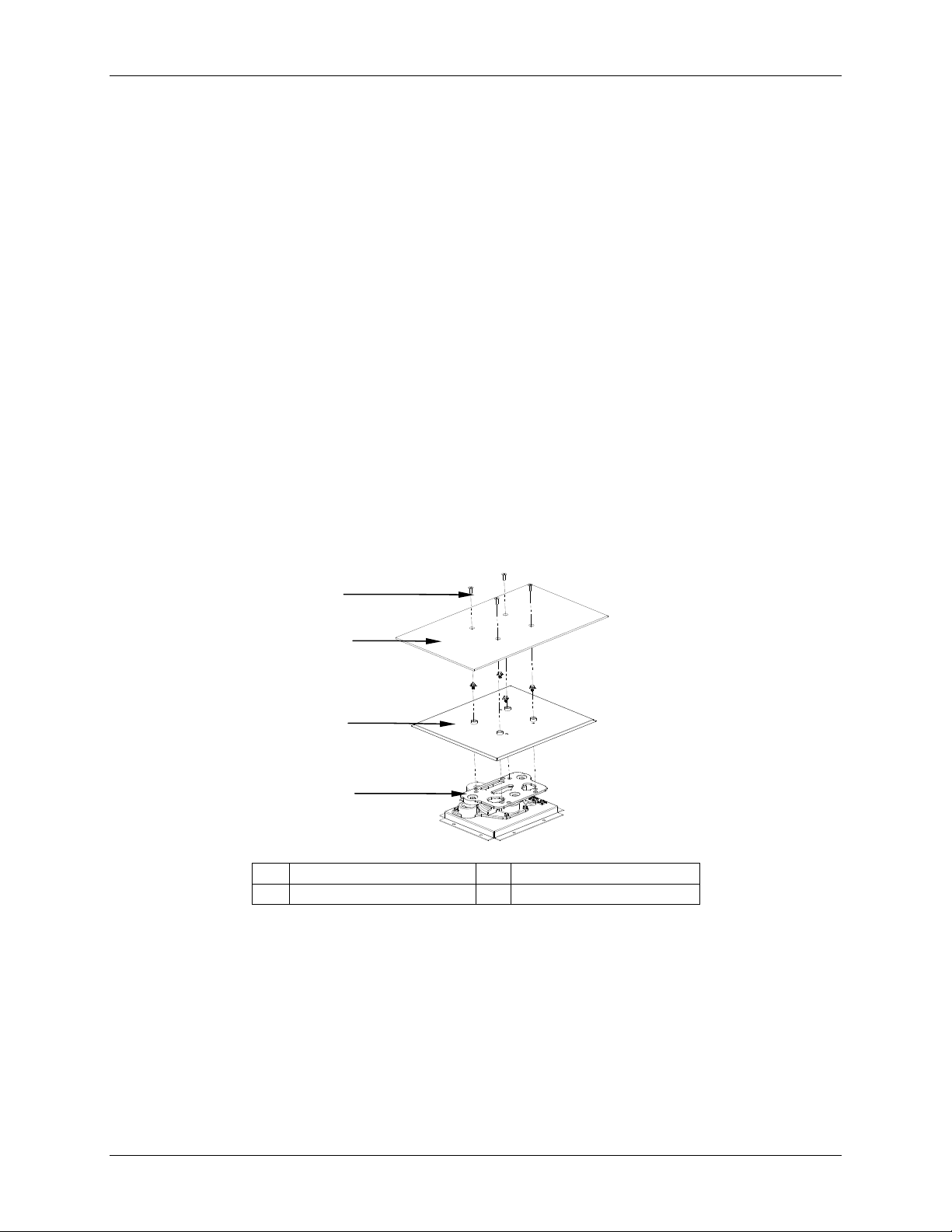
6.2 Installation of Platform
Prior to use, a spill cover and platform must be installed on the shaker. The shaker
is shipped with four Allen head platform screws installed in the bearing housing (see
Figure 5 below, which also shows the spill cover that you must install).
Figure 5: Installing Platform & Spill Cover
1
6
6
G
EETTTTIINNGG
G
S
TTAARRTTEED
S
D
2
3
4
1 Platform screws 3 Spill cover
2 Platform 4 Bearing housing
6.3 Installation of Clamps
Flask clamps purchased for use with universal platforms (see Section 9.11.2) require
installation. Clamps are installed by securing the base of the clamp to the platform with
the correct type and number of screws. All clamps are shipped complete with hardware.
Innova 43 & 43R Incubator Shakers M1320-0050 Operating manual
Page 23

23
2
Clamps for 2-, 2.8-, 4- and 6-liter flasks are shipped with an additional girdle to keep the
flasks in place (see Figure 6). To install these double girdle clamps:
1. Place clamp on platform, secure in place with correct type of screws: #S2116-3051,
10-24 x 5/16-inch flat Phillips head, provided with the clamps (see Figure 6a).
2. Place the loose girdle around the upper portion of clamp body so that it is held in
place by the legs of the clamp.
3. Insert the flask into the clamp, and push the girdle down so the rubber tubes are in
contact with the platform and the flask.
Figure 6: Double Girdle Clamp Installation
3
1
1 Platform 4 Clamp body (legs & base)
2 Clamp mounting holes (5) 5 Lower girdle with girdle tubes
3 Upper girdle with girdle tubes
Figure 6a: Clamp Fastener
6.4 Electrical Connections
Before making electrical connections, verify that the power source voltage matches the
voltage on the electrical specification plate and that the
position. The electrical specification plate is located on the rear panel of the shaker near
the power connector.
5
4
ON/OFF switch is in the OFF
New Brunswick Operating manual
Page 24

24
Connect the power cord to the power connector, then connect the other end to a suitable,
grounded receptacle. Make sure there is enough clearance to disconnect the plug
whenever necessary.
Figure 7: Rear Panel
1
2
3
1 Power connector
2 Exhaust vents: do not block!!
3 Adjustable foot
6.5 Optional Gassing Manifold Kit
This option is factory-installed. The manifold delivers gas into the chamber via as
many as 12 ports (see Figures 8 & 9 on the following page). The manifold can be
adapted to the desired tubing configuration by adding or subtracting ports or by
temporarily clamping off unused tubes. You may elect to use splitters (barbed Yconnectors) after the manifold to increase the number of flasks you can serve.
You determine the appropriate gas flow rate using a pressure regulator (which you
supply) on the gas supply.
NOTE:
Gas supply should be regulated and it must never exceed 15 PSIG.
50 feet of 1/16-inch (ID) sterilizable silicone tubing is supplied with the kit. Filters may
be needed: 0.22μ syringe filters (which you supply) can be fitted to the individual
manifold ports to maintain a sterile barrier.
Innova 43 & 43R Incubator Shakers M1320-0050 Operating manual
Page 25

25
Figure 8: Gas Monitor (optional)
Figure 9: Gas Fitting (with optional Gas Manifold)
1
1 Gas manifold connection (1/4 FNPT)
SAFETY PRECAUTIONS!
Never use the gas manifold with flammable gases.
Never exceed 15 PSIG inlet pressure to the manifold.
Make sure free lengths of tubing are secured by the hook and loop straps
to keep them from contact with flasks or other moving parts.
New Brunswick Operating manual
Page 26
26
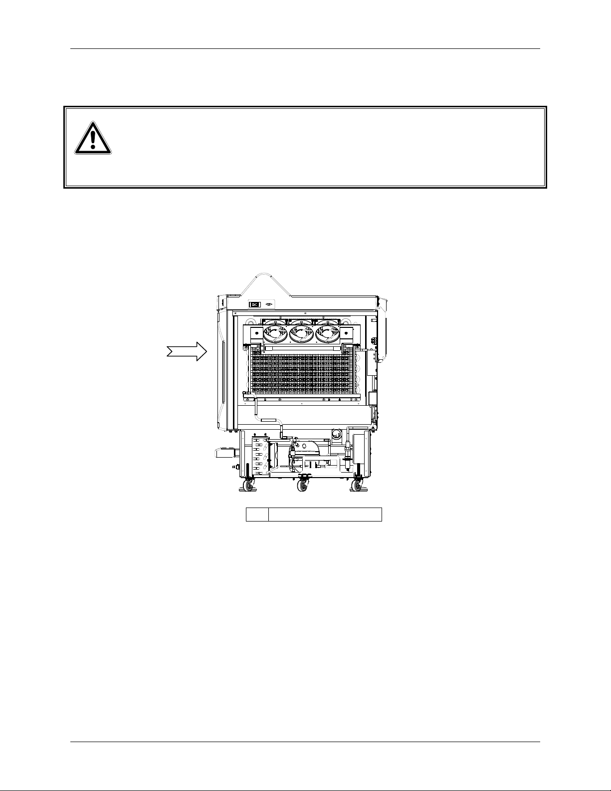
6.6 Optional Germicidal UV Lamp
WARNING!
Never try to operate the UV Germicidal Lamp while the shaker lid is open.
This option, a germicidal ultraviolet lamp, is placed inside the Service Compartment (see
Figure 10), outside the chamber to help reduce the risk of contamination. The lamp is
identified on the display screen as UV.
Figure 10: Germicidal UV Lamps (optional)
1
1 Front of shaker
The UV germicidal lamp is factory-installed and available on refrigerated shakers only.
Operation instructions are provided with this option (see Section 9.11.7).
6.7 Optional Photosynthetic Lamps
This factory-installed option, available on refrigerated shakers only, provides nine
photosynthetic growth lamps inside the chamber (see Figure 11 on the following page).
They can be turned on and off manually, by the easily set programmable timer, or by
computer. These lamps are identified on the display screen as GRO. The replacement
bulb part number is P0300-0221.
Innova 43 & 43R Incubator Shakers M1320-0050 Operating manual
Page 27

27
The recommended operating temperature when using this option is 15 - 37ºC; the
maximum operating temperature is 70ºC.
Figure 11: Photosynthetic Lamps (optional)
1 Photosynthetic lamp assembly
6.8 Optional Humidity Monitor
This optional factory-installed accessory allows you to monitor relative humidity levels
in the chamber throughout your run.
New Brunswick Operating manual
Page 28

28
Figure 12a: Humidity Monitor (optional)
1
1 Humidity monitor
When the humidity sensor is present in the chamber, maximum shaker temperature is
automatically limited to 60°C.
Specifications:
Humidity operating range: 0 to 100% RH Accuracy: See Figure 12b
Temperature operating range: 4 to 60ºC Hysteresis: ± 1.5% RH
Recovery time after saturation: 10 seconds Long term stability: 0.5% RH per year
Figure 12b: RH Sensor Operating Range & Humidity Error Graph
100
+/- 5 % E rro r
INTERMITTENT
OPERATION
+/- 3 % E rro r
+/- 5 % E rro r
0 102030405060
Temperature (C)
90
80
70
60
50
% RH
40
30
20
10
0
Innova 43 & 43R Incubator Shakers M1320-0050 Operating manual
Page 29

29
Figure 12c: RH Sensor Connection
1
M1282-7002
M1282-7012
1 Board inside the service compartment
Figure 12d: Humidity Sensor Mounting
1
1 Inside wall of cabinet
CAUTION!
Operating the Innova 43/43R at temperatures above 60ºC can result in
permanent damage to the sensor.
Water can be added to the spill pan in order to elevate the humidity level in the chamber.
See Section 6.9 for instructions.
6.9 Filling the Water Reservoir
If you choose to use the spill pan as a water reservoir to reduce evaporation and to raise
the humidity level in the chamber:
New Brunswick Operating manual
Page 30

30
1. Open the lid and temporarily remove the platform.
2. Make sure that the drain check valve is closed.
NOTE:
As you add water, do not allow the water to splash or flow into the recessed
middle of the pan, where the bearing housing assembly is mounted. Pour
water very slowly into the shallow area beyond the edge of the spill cover to
protect the bearing housing.
3. Accessing the pan/reservoir from the left, the right or in front of the spill cover,
slowly fill the reservoir with no more than 3 liters of distilled water. A long, narrow
watering can or a flexible hose will make it easier to access the pan while protecting
the bearing housing from accidental overflow.
At a 37°C setpoint, the chamber loses approximately 500 mL/hr from the pan.
At a 25°C setpoint, and placed in a 25°C room, the chamber achieves a relative humidity
equilibrium that is approximately 15% above the ambient humidity.
6.10 Draining the Water Reservoir
To drain water from the water reservoir/spill pan:
1. Attach the quick-connect drain fitting, direct it to a container or drain, and allow the
water to gravity drain.
2. When the reservoir is empty, detach the fitting.
The spill pan/water reservoir drain is located in the front, on the left, under the humidity
tray.
Innova 43 & 43R Incubator Shakers M1320-0050 Operating manual
Page 31

31
7.1 Safety Precautions
Before operating the shaker, verify that anyone involved with its operation has been
instructed in both general safety practices for laboratories and specific safety practices for
this apparatus.
The user is also responsible for following local guidelines for handling hazardous
waste and biohazardous materials that may be generated from the use of this
equipment.
If service should be required on a shaker that is going to be returned to an
Eppendorf facility, it must be completely decontaminated and cleaned prior to its
return.
It is the responsibility of the user to carry out appropriate decontamination
procedures if hazardous material is spilled on or inside the equipment. Before
using any cleaning or decontamination method other than those suggested by the
manufacturer, users should check with Eppendorf that the proposed method would
not damage the equipment.
This equipment is not “explosion-proof” and should never be used with flammable
substances or used to grow organisms that produce flammable by-products.
7
7
O
PPEERRAATTIIOON
O
N
CAUTION!
To prevent damage to the shaker and its contents, never run the shaker
without a platform.
7.2 Opening the Lid
Open the lid by firmly pressing the foot pedal or lifting up on the front handle. The lid
will stand open on its hinges until you swing it down to the closed position.
New Brunswick Operating manual
Page 32

32
7.3 Starting the Shaker
To initially start the shaker, close the lid and turn the power switch (located on the
righthand side of the control panel) to the ON position. The display will come on (first
showing only
or
43R, and the stroke, 1 inch or 2 inch, and then quickly moving into the Display
New Brunswick Scientific, then briefly displaying the model number, 43
screen), and the audible alarm will sound. To mute it, see Section 7.6.
When the shaker begins to operate, the LCD display will track the speed as it accelerates
to the last entered setpoint. The shaking action may be started or stopped by pressing the
Start/Stop button on the front panel.
NOTE:
The shaker will not operate if the lid is open. This is indicated by the “lid
open” symbol appearing in the bottom line of the display (see Figure 4 or
Table 3).
7.4 Using the LCD Screens
7.4.1 Display Screen
When you turn the power on, this is the first screen to appear after the company
title screen. The default display parameters are temperature (ºC) and shaking
speed (RPM).
You can change the displayed parameters. To replace a parameter:
1. Using the Control Knob, highlight the parameter that you wish to replace. For
this example, we will replace RPM (see Figure 13).
NOTE:
If you highlight an item, change it, but do not save your selection, after a few
seconds the screen will revert to its previous setting.
NOTE:
“UV” (UV Germicidal lamp) and “GRO” (photosynthetic growth lamps) will
appear in this screen with the word “NONE” if your shaker is not equipped
with these optional features.
Innova 43 & 43R Incubator Shakers M1320-0050 Operating manual
Page 33

33
Figure 13: Changing Display Parameter
ºC 23
RPM 120
DISP We 13:44
2. Click the Control Knob in.
3. Turn the Knob until the desired parameter appears in the highlighted field.
For this example, we will select
4. Click the Knob in, to set and save the parameter (see Figure 14).
Figure 14: Changed Display Parameter
RPM will flash.
HRS.
ºC 23
HRS 0.0
DISP We 13:44
You can also use this screen to verify a setpoint, even though the values displayed
here are actual (current) values. To view a setpoint:
1. Use the Control Knob to highlight the value (in this example, we will view the
temperature setpoint, so we will highlight the current
2. Click the Knob in to display the current setpoint, which will flash.
At this point you can modify the setpoint or click the Knob in again to return to
the normal display, which will be the actual temperature.
ºC, which is 23).
New Brunswick Operating manual
Page 34

34
To modify a setpoint in this screen:
1. Use the Control Knob to highlight the current value (we will continue to use
the temperature as our example, so we will select 23).
2. Click the Knob in to display the current setpoint (in this example, 38.5—see
Figure 15), which will flash.
Figure 15: Changing Setpoint
ºC 38.5
RPM 120
DISP We 13:44
3. Turn or spin the Knob to reset the setpoint (in this example, turn the Knob left
to decrease the setpoint to 37.0).
NOTE:
If you turn the Control Knob slowly, one click left or right will change the
setpoint by an increment of one tenth of a degree Celsius (0.1ºC). If you spin
the Knob, the value will change by larger increments.
4. Click the Knob in to set and save this new setpoint.
NOTE:
If you highlight an item, change it, but do not save your selection, after a few
seconds the screen will revert to its previous setting.
5. The display will automatically return to the actual value.
To move out of this screen and into the next:
1. Use the Control Knob to highlight DISP, then click the Knob in. DISP begins
to flash.
2. Turn the Knob to the right until the next screen, Summary (
If you turn too far and enter another screen, just turn the Knob back to the left
to recapture the
3. Click the Knob in to select the screen and to work in it.
SUMM screen.
SUMM), appears.
Innova 43 & 43R Incubator Shakers M1320-0050 Operating manual
Page 35

35
7.4.2 Summary Screen
In this screen (see Figure 16), you can see both the current ACTUAL readings and
the SETpoints for shaking speed (RPM), chamber temperature (ºC), elapsed time
in a programmed run (
(see Section 9.11.8), the percentage of relative humidity (
PARAM ACTUAL SET
HRS) and, if you are using the optional Humidity Monitor
%RH).
Figure 16: Summary Screen
RPM 100 100
ºC 45.1 45.0
HRS 0.0 0.0
%RH 50.0 N/A
SUMM Th 16:18
NOTE:
The current day (Su, Mo, Tu, We, Th, Fr or Sa) and time always remains
visible in the lower righthand corner.
The only elements you can modify in this screen are setpoints. To change
setpoints in this screen:
1. Turn the Knob until the desired setpoint is highlighted, then click the Knob in.
The setpoint will begin to flash.
2. Turn the Knob to the right to increase the number, or to the left to decrease it.
One click left or right will increase the setpoint by an increment of one (one
whole unit or one tenth unit, depending on the parameter). Move the Knob
more rapidly (you can spin it) to change the value by larger increments.
3. Click the Knob in to set and save the new value.
NOTE:
If you highlight an item, change it, but do not save your selection, after a few
seconds the screen will revert to its previous setting.
4. Repeat the above steps to change any or all of the other setpoints.
New Brunswick Operating manual
Page 36

36
To move out of this screen and into the next:
1. Use the Control Knob to highlight SUMM, then click the Knob in. SUMM
begins to flash.
2. Turn the Knob to the right until the next screen, Setup (SET), appears. If you
turn too far and enter another screen, just turn the Knob back to the left to
recapture the SET screen.
3. Click the Knob in to select the screen and to work in it.
7.4.3 Setup Screen
Here you can set the day of the week and the time (on a 24-hour clock). This
screen also allows you to lock all of your settings from further changes, and to
mute or enable the audible alarm.
Figure 17: Setup Screen
SETUP
Day : Thu
Hour/Min : 16:19
Lock : Off
Mute : Off
SET Th 16:19
To change the day:
1. Turn the knob to highlight the day (Thu in the sample screen above), then
click inward once. The day will flash.
2. Turn the knob left or right to select the day of choice: Sun, Mon, Tue, Wed,
Thu, Fri or Sat.
3. Click the knob in to set and save your choice.
NOTE:
If you highlight an item, change it, but do not save your selection, after a few
seconds the screen will revert to its previous setting.
Innova 43 & 43R Incubator Shakers M1320-0050 Operating manual
Page 37

37
To change the time (Hour/Min):
1. Turn the knob to highlight the time (16:19 in the sample screen above), then
click inward once. The time will flash.
2. Turn the knob left or right to change the time. Left moves backward, right
moves forward in time. One click right or left changes by one minute; spin
the knob to move more rapidly.
3. Click the knob once inward to set and save your choice.
To lock the settings:
1. Turn the knob to highlight Lock, then click inward once. The current status
(Off in the sample screen above) will flash.
2. Turn the knob in either direction; the only other choice is
inward to select and save
On, or continue turning to return to Off.
On. Click once
3. When you set Lock to On, a padlock icon (see Section 5.4) will appear at the
bottom of the screen. This icon will remain on display through all main
display screens until you turn the locking function off.
To mute the audible alarm:
1. Turn the knob to highlight Mute, then click inward once. The current status
(Off in the sample screen above) will flash.
2. Turn the knob in either direction; the only other choice is On. Click once
inward to select and save On, or continue turning to return to Off.
3. When you set Mute to On, the icon will appear at the bottom of the
screen. This icon will remain on display through all screens until you turn the
muting function off.
To move out of this screen and into the next:
1. Use the Control Knob to highlight
SET, then click the Knob in. SET begins to
flash.
2. Turn the Knob to the right until the next screen, Lamps (
you turn too far and enter another screen, just turn the Knob back to the left to
recapture the
LAMP screen.
3. Click the Knob in to select the screen and to work in it.
7.4.4 Lamps Screen
In this screen (see Figure 18), you can turn the chamber light (Chamber), the
optional UV germicidal (“decontamination”) lamp (
photosynthetic growth lamps (
Growth) on and off.
LAMP), appears. If
UV Decont) and the optional
New Brunswick Operating manual
Page 38

38
On means the light is always on, and Off means the light is always off, unless you
add additional programming.
There is an additional mode for the chamber light: Auto. In Auto mode, the light
will go on every time you activate the control knob or open the lid. This is the
default mode.
NOTE:
The Lamps screen, shown below, will always indicate Chamber light mode. If
the shaker is not equipped with the optional UV germicidal lamp and/or
photosynthetic growth lamps, UV Decont and/or Growth will say None.
Figure 18: Lamps Screen
LAMPS
Chamber : Auto
UV Decont : Off
Growth : Off
LAMP Th 16:20
To change the mode setting for any of the lamps:
1. Turn the Control Knob to highlight the setting for the lamp of choice, then
click the knob in. The current setting will flash (in the sample screen, we will
use the
2. Turn the Knob left or right until the desired mode setting appears (Auto in this
example).
3. Click the Knob in to save the new setting.
NOTE:
If you highlight an item, change it, but do not save your selection, after a few
seconds the screen will revert to its previous setting.
To move out of this screen and into the next:
1. Use the Control Knob to highlight
begins to flash.
Chamber light as an example.
LAMP, then click the Knob in. LAMP
Innova 43 & 43R Incubator Shakers M1320-0050 Operating manual
Page 39

39
2. Turn the Knob to the right until the next screen, RS232 (COMM), appears. If
you turn too far and enter another screen, just turn the Knob back to the left to
recapture the COMM screen.
3. Click the Knob in to select the screen and to work in it.
7.4.5 RS232 Screen
This screen (see Figure 19) is used only if you have connected a personal
computer to the RS-232 port (see Section 5.8). Here you can select the RS-232
port’s Mode and the Baud Rate appropriate to your PC.
Figure 19: RS232 Screen
RS232
Mode : Off
Baud Rate : 19200
1
F/W Rev : D/H
2
COMM Th 16:21
1 FirmWare Revision level (this line is for information only)
2 In this sample screen, the Display is at Revision D and the FirmWare Control Board is at
Revision H.
To change the Communication Mode:
1. Turn the Control Knob to highlight the current setting (
screen above), then click the Knob in. The current setting will flash.
2. Turn the Control Knob left or right until the desired mode setting appears (see
Table 5: Communication Mode, on the following page).
Off in the sample
New Brunswick Operating manual
Page 40

40
Table 5: Communication Mode
Mode Application
Off The RS-232 port is not open to communication in
either direction.
Slave The shaker can be fully controlled from the
computer.
Talk The shaker sends current value reports to the
computer once per minute.
Monit [Monitor] The shaker responds only to “Report Requests”.
3. Click the control knob inward once to save the new setting.
NOTE:
If you highlight an item, change it, but do not save your selection, after a few
seconds the screen will revert to its previous setting.
To change the Baud Rate:
1. Turn the control knob to highlight the current setting (19200 in the sample
screen above), then click the knob inward once. The current setting will flash.
2. Turn the control knob left or right until the desired setting appears: 9600,
19200 or 38400. The setting you choose should match the baud rate of your
computer.
3. Click the control knob inward once to save the new setting.
To move out of this screen and into the next:
1. Use the Control Knob to highlight COMM, then click the Knob in. COMM
begins to flash.
2. Turn the Knob to the right until the next screen, Calibrate (
CAL), appears. If
you turn too far and enter another screen, just turn the Knob back to the left to
recapture the CAL screen.
3. Click the Knob in to select the screen and to work in it.
7.4.6 Calibrate Screen
Use this screen (see Figure 20 on the following page) to create a temperature
offset and to calibrate the shaking speed (for details, see Sections 7.7,
Temperature Offset Calibration, and 0, Using Calspeed).
Innova 43 & 43R Incubator Shakers M1320-0050 Operating manual
Page 41

41
Figure 20: Calibrate Screen
CALIBRATE
°C Offset : 0.0
Calspeed : 250
CAL Th 16:22
1 This is a sample of the Indicated RPM Value.
7.4.7 Programs Screen
Use this screen (see Figure 21) to set as many as four operating programs for the
shaker. Each program can have as many as 15 steps. See Section 7.5 below for
complete details.
Figure 21: Programs Screen
1
PROGRAMS
Program 1 : Off
Program 2 : Off
Program 3 : Off
Program 4 : Off
PROG Th 16:23
New Brunswick Operating manual
Page 42

42
7.5 Programming the Shaker
7.5.1 Timer Only
By setting an HRS setpoint in the DISP or SUMM screen, the shaker may be set to
automatically stop after a preset time period of 0.1 to 99.9 hours.
If the time is set to 0.0, the shaker will operate continuously until either the lid is
opened or the Start/Stop button is pushed.
7.5.2 Programmed Steps
The resident software for the Innova 43/43R can store up to four programs, each
having as many as 15 steps. Each step can be programmed in one-minute
increments, for total periods of one minute up to 99 hours 59 minutes each.
To enter the programming mode, use the Control Knob to select the PROG screen
(see Figure 21, repeated below). At this point, you can Run a program, Edit a
program, generate a New program or turn a program Off. Off is the default mode.
Figure 21: Programs Screen
PROGRAMS
Program 1 : Off
Program 2 : Off
Program 3 : Off
Program 4 : Off
PROG Th 16:23
7.5.3 Creating a Program
To write a New program:
1. Use the Control Knob to highlight the mode of Program 1 (in our sample
screen, Figure 21, it is
to flash.
Off), then click the Knob in. The selected field begins
Innova 43 & 43R Incubator Shakers M1320-0050 Operating manual
Page 43

43
2. Turn the Knob until the field says New. Click the Knob in to select this
mode. The screen for Program 1 - Step 1 will open (see Figure 22):
Figure 22: Program 1 – Step 1
PRG1 - STEP -- 01
Time 00:00
ºC 20.0
RPM Off
UV Off
GRO Off
Save Cancel
1 Step number
2 Use “Cancel” to leave the programming mode without saving any new settings.
3 Use “Save” to leave the programming mode and save all new settings. Do NOT use
“Save” until the programming is complete.
4 Use these arrows to scroll through the programming steps.
NOTE:
If your shaker is not equipped with these optional features, “UV” and “GRO”
will appear with the word “Off” in this screen but will not be programmable.
3. Turn the Knob to highlight the Time setting (00:00 in the sample screen
above), then click the Knob in. The field will flash.
4. Turn the Knob until the desired running duration for this step (from 00:01,
which means one minute, to 99:59) appears, then click the Knob in to save the
setting. We will set Step 1 time to eight hours for this example (see Figure 23).
5. Turn the Knob to highlight the
screen above), then click the Knob in. The field will flash.
6. To set the temperature desired (ºC from 4.0 to 80.0) for the time period you
have set, turn the Knob (left to decrease, right to increase). When the desired
value appears, click the Knob in to save the setting. We will set Step 1
temperature to 37.0ºC (see Figure 23).
ºC temperature setting (20.0 in the sample
New Brunswick Operating manual
Page 44

44
7. Turn the Knob to highlight the RPM setting (Off in the sample screen above),
then click the Knob in. The field will flash.
8. Turn the Knob to select the desired shaking speed (25 to 400 RPM) for this
time period, then click the Knob in to save the setting. We will set Step 1
speed to 150 RPM (see Figure 23).
9. If you do not have the optional UV lamp, skip this step. If you have the UV lamp
(default setting is Off) and you wish to have it on during the time period you
have set, use the Control Knob to select the field, click the Knob to select the
field (it will flash), turn the Knob to select On, then click the Knob in to save
the setting. In our sample Step 1 (see Figure 23), however, UV remains Off.
10. If you do not have the optional GRO lamps, skip this step. If you have the
photosynthetic lamps (default setting is Off) and you wish to have them on
during the time period you have set, use the Control Knob to select the field,
click the Knob to select the field (it will flash), turn the Knob to select On,
then click the Knob in to save the setting. In our sample Step 1 (see Figure
18), however, GRO remains Off.
NOTE:
DO NOT select “Save” yet!
11. To program Step 2 (see sample screen in Figure 23): use the Control Knob to
highlight the arrows at the bottom left of the screen. Click the Knob to make
the arrows flash, then turn the Knob to the right until Step 2 appears. Click
the Knob in to work in this screen, and repeat Steps 3-10.
Figure 23: Program 1 – Step 2
PRG1 - STEP 01 02
Time 08:00 03:00
ºC 37.0 40.0
RPM 150 225
UV Off Off
GRO Off Off
Save Cancel
1 Current step number
1
Innova 43 & 43R Incubator Shakers M1320-0050 Operating manual
Page 45

45
Whatever step is shown on the right-hand side of the display is settable (in Figure
23, it is Step 2). To scroll between steps, select the arrows (bottom left), then turn
the Control Knob clockwise or counterclockwise, then select the desired step.
NOTE:
The time entered for each step is for that step only; it is not cumulative (i.e.,
the elapsed time from the start of the program).
12. Continue to program as many as 15 steps in the same manner. For our sample
program, we have only three steps (see Figure 24).
Figure 24: Program 1 – Step 3
PRG1 - STEP 02 03
Time 03:00 12:00
ºC 40.0 4.0
RPM 225 0
UV Off Off
GRO Off Off
Save Cancel
The three-step program we have illustrated is designed to start incubating cultures
at 37ºC and hold that temperature for eight hours, shaking at 150 RPM. After
eight hours, Step 2 engages, increasing the temperature setpoint to 40ºC for a
temperature induction, holding that temperature for three hours and increasing the
shaking speed to 225 RPM. After this interval, the temperature will be cooled to
4ºC and held at that temperature for twelve hours; no shaking will occur during
this period, as the speed is set to 0 RPM.
Please note that temperature reductions, even at temperatures above ambient
(going from 40º to 30ºC, for example), require refrigeration to be effective.
To save the entire program:
1. Once all your steps are set, use the Control Knob to highlight Save at the
bottom of the screen, then click the Knob in. The field will flash.
2. Click the Knob in again to save the program. The display will read
Running – Saving Profile
PROG) screen.
(
If you wish, you can set Programs 2, 3 and 4 and save them in the same manner.
for a few seconds, then return to the main Programs
Process
New Brunswick Operating manual
Page 46

46
7.5.4 Editing a Program
Use the Edit function to open a program you have already created and saved, in
order to modify your settings following the same procedures.
7.5.5 Running a Program
Use the Run fuction to turn a specific program on. Naturally, only one program
can run at a time. When you change the mode to Run, the screen will show the
Run icon ( ):
Figure 25: Programs Screen – Running
PROGRAMS
Program 1 : Off
Program 2 : Run
Program 3 : Off
Program 4 : Off
PROG Fr 08:31
To stop a program: You can abort a run any time by changing the program’s
function to Off.
7.6 Muting the Audible Alarm
The Innova 43/43R shakers have an audible alarm that is activated under predetermined
conditions (see Table 4). It may be muted in the following way:
1. Turn the Control Knob until the
Knob in to work in this screen.
2. Turn the Knob to highlight the
the alarm is audible). To mute the alarm, click the Knob in. The field will flash.
3. Turn the Knob to change the setting to
4. To reactivate the audible alarm at any time, repeat steps 1-3, reversing
SET screen is highlighted on the display. Click the
Mute mode (the default setting is Off, which means
On, then click the Knob to save this selection.
Off and On.
Innova 43 & 43R Incubator Shakers M1320-0050 Operating manual
Page 47

47
7.7 Temperature Offset Calibration
The temperature probe and the temperature controller are calibrated together at the
factory. The temperature probe measures the temperature of the air at the probe’s
location, near the return vent. The controller uses the probe input to adjust air
temperature, up or down, to match the temperature setpoint.
Depending on various conditions within the chamber, such as flask placement and size,
the heat produced by growing organisms, heat losses due to liquid evaporation from
flasks, etc., the display temperature may differ from temperatures within the flasks
themselves. You can calculate the correction value for this offset and program the shaker
to display a corrected temperature.
7.7.1 Calculating the Offset Value
If you wish to have the temperature display (“Indicated Temperature”) match the
temperature at a given point, or match the average of a series of points within the
chamber (“Actual Temperature”), proceed as follows:
1. Let the shaker equilibrate at or near the desired temperature, then record the
Indicated Temperature.
2. Now record the Actual Temperature.
3. Calculate the temperature correction value using this formula:
Actual Temperature – Indicated Temperature = Temperature Offset Value.
4. To set the Temperature Calibration Offset, follow the procedure outlined in
Section 7.7.2 below.
7.7.2 Setting the Offset
To set the temperature calibration
Offset:
1. Use the Control Knob to enter the CAL screen (see Figure 20, repeated
below).
2. Turn the Control Knob to highlight the current setting (
0.0 in the sample
screen above), then click the Knob in. The current setting will flash.
3. Turn the Knob (left for negative settings or right for positive settings) to
display the desired setting. As you turn the Knob, each click represents one
tenth of a degree Celsius (0.1ºC).
4. When you reach the desired setting, click the Control Knob in to save the new
value.
New Brunswick Operating manual
Page 48

48
5. When the Temperature Offset is set to any value other than 0, the icon
will appear next to ºC in the DISP and SUMM screens.
NOTE:
If you highlight an item, change it, but do not save your selection, after a few
seconds the screen will revert to its previous setting.
Figure 20: Calibrate Screen
CALIBRATE
°C Offset : 0.0
Calspeed : 250
CAL Th 16:22
7.8 Using Calspeed
The Calspeed function, which is set in the CAL screen (see Figure 20 above), is used to
calibrate the speed of the shaking mechanism. Calibrated at the factory, speed does not
need to be recalibrated until a major operating component (e.g., drive belt) is changed.
NOTE:
Prior to calibrating the speed, make sure that the platform is properly secured
to the subplatform, and any flasks present are secured.
When the shaker is running, the
to calibrate the speed, set the speed to a value that can be measured— a setpoint of 250
RPM works well. The use of a strobe is recommended for accuracy. If, after measuring
the actual speed, you wish to adjust the indicated value:
1. Click the Control Knob in.
2. Set the new value.
3. Click the Knob in again to save the setting.
4. Turn the shaker
OFF, wait a few seconds, then turn the shaker back ON.
CAL screen shows the indicated RPM value. If you wish
Innova 43 & 43R Incubator Shakers M1320-0050 Operating manual
Page 49

49
7.9 Power Interruption
In the event of a power failure, the Innova 43/43R Shakers are equipped with an
automatic restart function. The shaker’s non-volatile memory retains all stored
information.
If the shaker was in operation prior to the power interruption, the shaker will begin to
operate at its last entered setpoints. The alarm/POWER display will flash, indicating that
a power interruption has occurred. Turn the Control Knob in any direction to
acknowledge the visual alarm. The flashing will stop.
New Brunswick Operating manual
Page 50
50
8
8
WARNING!
When cleaning the shaker, always turn off the shaker and disconnect the
power cord from the power supply.
8.1 Routine Maintenance
No routine maintenance schedule is required for the Innova 43 and 43R.
To ensure that your shaker retains its attractive appearance, an occasional cleaning, using
a cloth with conventional household (non-abrasive) cleaner is recommended (see Section
8.2 below for more details).
We also suggest that the area around the shaker be vacuumed or swept to remove dust
and other debris, ensuring proper air flow in and around the shaker.
M
AAIINNTTEENNAANNCCE
M
E
8.2 Cleaning External & Internal Surfaces
The shaker may be cleaned using a damp cloth or any standard household or laboratory
cleaner to wipe down its outer surfaces. Do not use abrasive or corrosive compounds to
clean this instrument, as they may damage the shaker and void the warranty.
If Biohazard decontamination is required, see Section 8.3 below.
8.3 Biohazard Decontamination
It is the responsibility of the user to carry out appropriate decontamination
procedures if hazardous material is spilled on or inside the equipment. Before
using any cleaning or decontamination method other than those suggested by the
manufacturer, users should check with Eppendorf that the proposed method would
not damage the equipment.
Commercially available household bleach solutions, when diluted at a 1:10 ratio, are
effective in routine decontamination of the instrument. The method for decontaminating
a spill depends upon the nature of the spill.
Innova 43 & 43R Incubator Shakers M1320-0050 Operating manual
Page 51
51
Spills involving fresh cultures or samples known to have low concentrations of biomass
should be flooded with decontamination solution and soaked for 5 min before cleanup.
Spills involving samples with high concentrations of biomass, or involving organic
matter, or occurring in areas warmer than room ambient temperature, should be exposed
to decontamination solution for at least one hour before cleanup.
WARNING!
Personnel involved in the cleanup of any spill should wear gloves, safety
glasses, and a laboratory coat or gown during the cleanup process.
Respiratory protection should be considered for spills where aerosolization
is suspected.
New Brunswick Operating manual
Page 52

52
9
9
9.1 Troubleshooting
If any problems occur with your shaker, do not attempt to perform any service on the
shaker other than specified in this manual. Unauthorized servicing may void the
warranty. Please contact your local Eppendorf Customer Service Department
In any correspondence with Eppendorf, please refer to the model number and serial
number of your shaker. This information is on the electrical specification plate, located
on the rear panel of the shaker, above the power connector.
There are some problems, however, that you can investigate and correct yourself. Refer
to the following Troubleshooting Guide:
Symptom(s) Probable Cause(s) & Solution(s)
Shaker does not run.
Shaker runs slowly
and/or no speed
indication.
No power; display is not on; power cord is not plugged in and/or
power switch is off: plug in power cord (to working electric
outlet), and turn on power switch.
Lid is open—look for Open Lid icon on display: close the lid
firmly.
Lid is closed but Open Lid icon is on display: lid switch is
broken; call for service.
On/Off switch is not working: call for service.
Fuse(s) burned out: check and replace as needed.
Shaking speed has been set to Zero by program running (look
for Run icon in display) or by computer interface: reset shaking
speed.
Defective main board: call for service
Defective display controller board: call for service.
Jammed shaking mechanism: call for service
Defective motor: call for service
Drive belt out of alignment or worn: call for service.
Fuse(s) burned out: check and replace as needed.
Incorrect speed calibration: recalibrate shaking speed.
Defective main board: call for service.
Defective motor: call for service.
Drive belt out of alignment or worn: call for service.
S
EERRVVIICCEE
S
...continued...
&
&
A
CCCCEESSSSOORRIIEES
A
S
Innova 43 & 43R Incubator Shakers M1320-0050 Operating manual
Page 53

53
Symptom(s) Probable Cause(s) & Solution(s)
Shaker does not run at
set speed.
Operating noise
Incubator does not
reach set temperature.
Incorrect temperature
indication.
Incorrect relative
humidity %
Shaker is running in Program mode (look for Run icon in
display).
Shaker speed has been changed by RS-232 command/
computer interface.
Shaker is overloaded: remove some contents & balance load.
Defective motor: call for service.
Drive belt out of alignment or worn: call for service.
Load out of balance: unload all contents from platform, then
reload.
Loose component(s) in Platform, subplatform, and/or drive
assembly: call for service.
Shaker running in Program mode: Run icon in display.
Temperature setpoint changed by RS-232/computer interface
command.
Heater fuse blown: replace.
Compressor fuse blown: replace.
Compressor over-pressure switch activated: call for service.
Chamber fans not working: call for service
Ambient temperature too high or too low: cool or heat the
room as needed.
Lid is not completely closed (even though Open Lid icon may
not be on display): open it and reclose it firmly.
Line voltage is too low.
Frequency on line voltage if set incorrectly: reset.
Defective heater: call for service.
Defective refrigeration system: call for service.
Incorrect temperature indication (see below).
Temperature Offset has been programmed (look for adjacent
to C on display).
Defective RTD assembly: call for service.
Defective main board: call for service.
Defective humidity probe or broken contact: call for service.
...continued...
New Brunswick Operating manual
Page 54

54
Symptom(s) Probable Cause(s) & Solution(s)
Photosynthetic GRO
lamp does not work.
UV germicidal lamp
does not work.
Shaker is running in Program mode (look for Run icon in
display), and program calls for GRO lamp to be off.
GRO lamp mode has been changed by RS-232 command/
computer interface.
Bulb is burned out; replace (see Section 9.6).
Fuse is burned out: replace (see Section 9.4)
Check ballast voltage.
Check cable connections.
Check switch settings.
GRO lamp mode has been changed by RS-232
command/computer interface.
Shaker is running in Program mode (look for Run icon in
display), and program calls for UV lamp to be off.
UV lamp is burned out; replace (see Section 0)
Fuse is burned out: replace (see Section 9.4)
Check ballast voltage.
Check cable connections.
Check switch settings.
UV lamp mode has been changed by RS-232 command/
computer interface.
9.2 Product Returns
Should you need to return your Innova 43/43R to Eppendorf for any reason. Contact
Eppendorf Customer for return instructions.
Innova 43 & 43R Incubator Shakers M1320-0050 Operating manual
Page 55

55
9.3 Opening the Service Compartment
WARNING!
Before opening the Service Compartment, always turn off the shaker and
disconnect the power cord from the power supply.
The Service Compartment (see Figure 26) contains the shaker’s electronic and
temperature control components. The user should access the Service Compartment only
to replace a fuse—see Section 9.4 for Fuse Replacement instructions). All other service
intervention are to be performed by authorized service technicians only.
9.4 Fuse Replacement
WARNING!
When replacing fuses, always turn off the shaker and disconnect the
power cord from the power supply.
There are four fuses that can be replaced by the user. These are located inside the
Service Compartment. To access the fuses (see Figure 26):
1. Turn the power off and unplug the shaker.
2. Remove the four screws and washers that hold the right side service panel grille in
place. Set them aside for reuse.
3. Fuses are numbered 1 through 4 (see Table 6); access the fuse you wish to replace by
using a coin or a blade screwdriver to turn and release the spring-loaded cap.
4. Replace the fuse with a new one of the same type and rating (see Table 6 below):
Table 6: Fuses
Fuse No. Function Type Rating
F1 Heater
F2 GRO Lamps (photosynthetic) 3.15 A
F3 UV Lamp (germicidal) 3.15 A
F4 Compressor 10 A
optional equipment
Slo Blo
®
8 A
New Brunswick Operating manual
Page 56
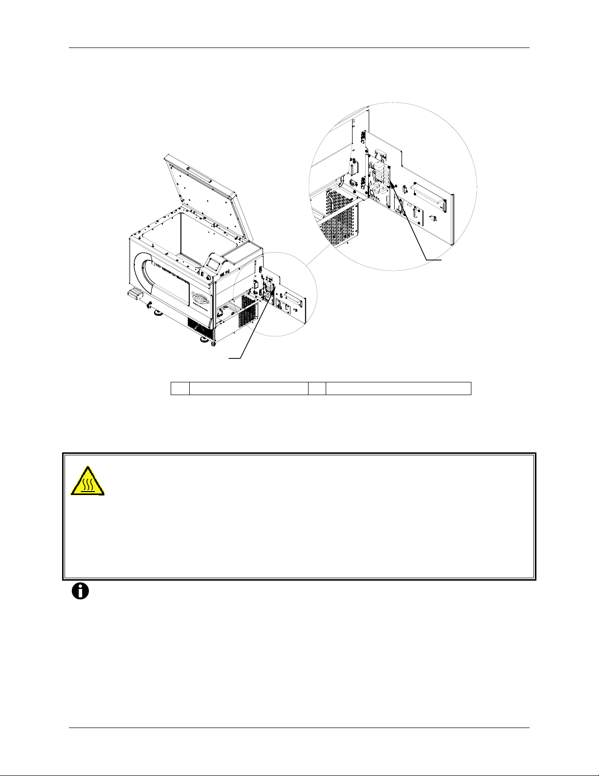
56
Figure 26: Fuse Replacement
1
2
1 Fuses (F1-F4) 2 Service Compartment
9.5 Replacing Cabinet Lights
WARNING!
Before installing or removing the quartz bulbs:
(1) Make sure power is disconnected from the shaker,
(2) Wear plastic gloves to protect the bulb from skin oils and to protect your
hands just in case the bulb should break,
(3) Before removal, make sure the bulb has fully cooled.
NOTE:
Cabinet lights are connected in series. When one burns out, both lights will
be off. It is therefore prudent to replace both bulbs at the same time.
Innova 43 & 43R Incubator Shakers M1320-0050 Operating manual
Page 57
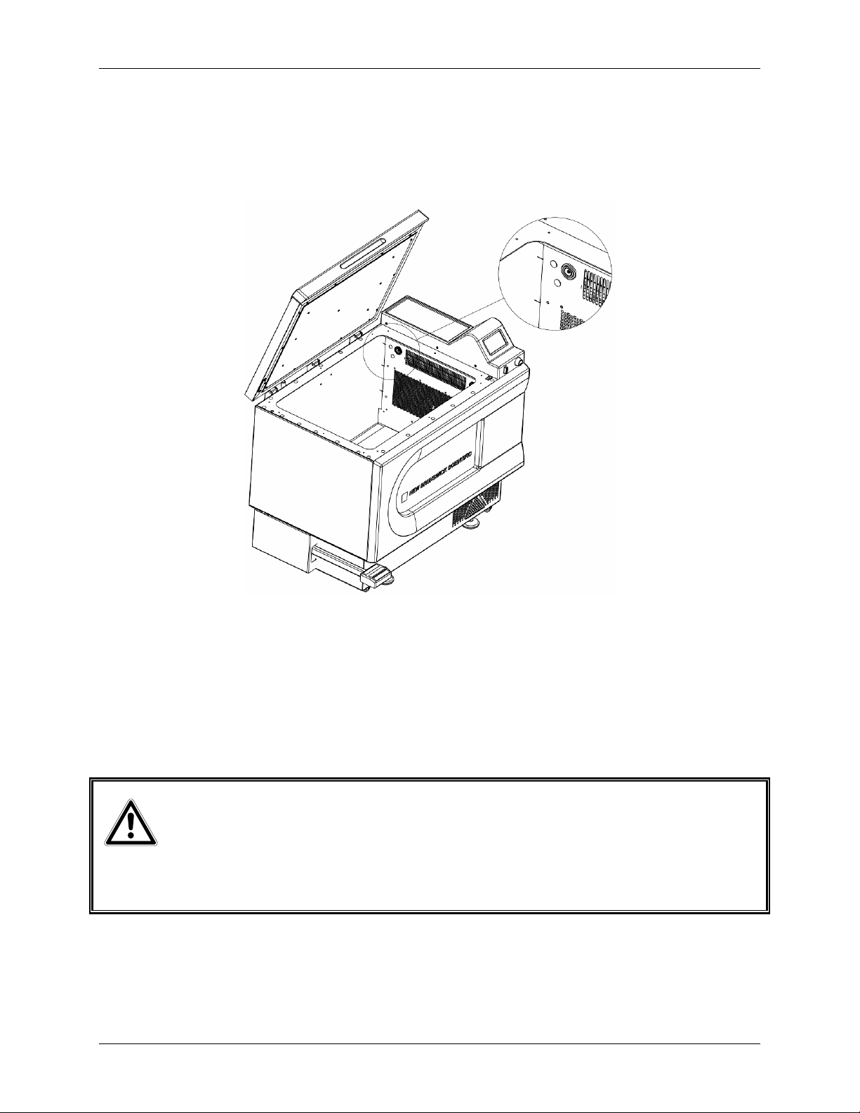
57
Be sure to follow all the WARNINGS and the NOTE above as well as the procedure
outlined below when you replace the cabinet bulbs with reference to Figure 27 below:
Figure 27: Replacing Cabinet Lights
1. Make sure power is disconnected from the shaker.
2. Open the lid.
3. Wearing plastic gloves, remove the first used bulb, then carefully insert the new
bulb’s prongs fully into the connector base.
4. Repeat step 3 for the second bulb.
9.6 Replacing Optional Photosynthetic Lamps
WARNING!
Before removing or installing the photosynthetic “GRO” lamp, make sure power
is disconnected from the shaker.
To replace the photosynthetic GRO lamp bulbs, with reference to Figure 28:
1. Make sure power is disconnected from the shaker.
2. Open the lid.
New Brunswick Operating manual
Page 58

58
3. Remove the two thumbscrews from the diffuser holder.
Figure 28: Replacing Photosynthetic Lamps
4. Remove the diffuser by placing a finger underneath and rotating the diffuser in the
slot at the back of the photosynthetic light assembly. All 9 lamps should now be
accessible to you.
5. To remove the lamp for replacement, rotate the lamp 90º, taking care to support the
lamp before it drops down.
6. To replace the lamp, orient the pins of the new lamp vertically. Simultaneously,
gently press both sides of the lamp into the slots.
7. Rotate the new lamp 90º. The lamp should catch in the holders on both ends. Make
sure both ends are secure.
8. Put the diffuser back in place, reinstalling the diffuser holder with its two
thumbscrews.
9.7 Adjusting Lid Tension
WARNING!
The following procedures are provided for your information only.
Do not attempt to perform these service interventions yourself unless you
are an authorized service technician.
Innova 43 & 43R Incubator Shakers M1320-0050 Operating manual
Page 59

59
In the event the lid does not stay in the fully open position, you may want to adjust the lid
tension: tighten the 5/16-inch nuts on the hinges to increase spring tension.
9.8 Replacing Optional Germicidal Lamp
WARNING!
Before installing or removing the germicidal “UV” lamp, the authorized
technician will:
(1) Make sure power is completely disconnected from the shaker,
(2) Wear plastic gloves to protect the lamp from skin oils and to protect
your hands just in case the lamp should break,
(3) Before removal, make sure the lamp has fully cooled.
To replace the UV lamp, your service technician will follow all the WARNINGS above
and the procedure and WARNINGS outlined below, with reference to Figure 29:
1. Make sure power is disconnected from the shaker.
2. Open the Service Compartment by removing the side panel.
3. Free the heater cable harness and the temperature probe from their tie wraps and
Permagum®.
Figure 29: Germicidal (UV) Lamp Replacement
NOTE that wires, tie wraps and Permagum® are not shown above.
4. Remove the evaporator cover from the Service Compartment, paying careful attention
to the drain tubes.
New Brunswick Operating manual
Page 60

60
5. Wearing plastic gloves, remove the germicidal lamp by pressing it toward the spring-
loaded tombstone. The lamp has a single pin at each end.
6. Still wearing plastic gloves, install a new lamp.
7. Pull the heater cable harness and temperature probe back through the holes in the
Service Compartment.
8. Replace the fan cover, making sure the heater cable harness wires and temperature
probe have been pulled through. Adjust the temperature probe position to ensure that
the probe tip can protrude 3 – 3.25 inches (7.6 – 8.2 cm) from the fan cover face.
9. Secure the heater cable harness and temperature probe with tie wraps, and add
Permagum® to fill the hole.
10. Reinstall the side panel that closes off the Service Compartment.
11. Use the plastic fitting to hold the temperature probe, ensuring that its tip is 3 – 3.25
inches (7.6 – 8.2 cm) from the fan cover face.
9.9 Belt Replacement or Adjustment
To gain access to the drive belt, your service technician will follow these steps with
reference to Figures 30 & 31 below:
1. Make sure that the power is switched off and the shaker is unplugged.
2. Open the lid and remove the platform.
3. Using a 7/32-inch Allen key (hex wrench), remove the four bolts that hold the
subplatform in place, and remove the subplatform.
4. Disconnect the motor wire by unplugging its connector.
5. With a wrench, remove the nuts that hold the bearing housing to the bottom
weldment.
6. Position the counterweight so it is closest to you, and tie it in place with tie wraps or
strong cord, in order to prevent it from dropping against your fingers or causing
you to lose your grip.
7. Remove the bearing housing with care: it weighs 47 lbs. / 21.3 kg.
8. Turn the bearing housing over to access the belt, motor and pulley.
Innova 43 & 43R Incubator Shakers M1320-0050 Operating manual
Page 61

61
Figure 30: Drive Assembly
1
2
3
1 Spill deflector 2 Drive assembly 3 Bearing housing
To replace the drive belt, follow these steps with reference to Figures 30 & 31:
1. Loosen the four hex nuts that hold the motor assembly in place and remove the old belt.
2. Guide the belt onto the two pulley grooves.
3. Tighten the motor nuts.
4. Check the belt adjustment by applying finger pressure to the belt midway between the
two pulleys. The belt should deflect approximately 3/8-inch (9-10 mm).
5. If the deflection is not right, loosen the nuts, readjust the belt, then retighten the
motor nuts.
New Brunswick Operating manual
Page 62

62
Figure 31: Belt Replacement & Adjustment
1
2
3
4
5
1 Drive belt 4 Four motor fixing bolts (loosen for belt tensioning)
2 Pulley 5 Motor
3 Bearing housing
If an adjustment is required:
1. Loosen the four hex nuts on the motor assembly.
2. Move the motor assembly until the belt is tight.
3. Tighten the hex nuts and recheck the belt tension by exerting pressure on the belt.
The belt should deflect approximately 3/8-inch (9.5 mm).
Reassembly:
1. In reverse order, reinstall the bearing housing. Once it is securely in place, remove
the tie wraps/cord.
2. Secure the wiring to ensure no interference during rotation.
3. Reinstall the subplatform and platform.
4. Recalibrate speed (see Section 0).
Innova 43 & 43R Incubator Shakers M1320-0050 Operating manual
Page 63

63
9.10 Replacement Parts
In Table 7 below you will find commonly needed replacement parts for your Innova
43/43R shaker:
Table 7: Replacement Parts
Part Description Quantity Part No.
Spare Parts Kit (includes 1 motor drive poly-V belt,
two each hinge assemblies, halogen bulbs, and
10A, 8A, & 3.15A fuses)
Spare Parts Kit (includes 1 motor drive poly-V belt,
and two each 10A, 8A, & 3.15A fuses)
Flask Clamp screws, 10-24 x 5/16-inch flat Phillips
head (+)
Test Tube Rack screws, 10-24 x ½-inch pan head,
and washers (#10 plain and #10 lock washers)
Motor Drive Poly-V Belt, 28 inches long 1 P0700-7070
Fuse, 10A 1 P0380-3162
Fuse, 8A 1 P0380-3630
Fuse, 3.15A 1 P0380-3460
Chamber Light Bulbs 2 P0300-0470
UV Germicidal Bulb (if so equipped) 1 P0300-0351
Photosynthetic Bulb (if so equipped) 1 P0300-0221
UV Germicidal Light Ballast (if so equipped) 1 P0420-5113
Photosynthetic Light Ballast (if so equipped) 1 P0420-5192
1 M1320-6000
1 M1282-6000
25 S2116-3051
10 each M1289-0800
9.11 Accessories
When ordering accessories, you may be asked to provide the model number and serial
number of your shaker. This information is on the electrical specification plate, located
on the rear panel of the shaker. The serial number is also labeled in the lower right
corner of the front panel, below the chamber lid seal.
9.11.1 Platforms
Table 8 lists the various solid 18- x 30-inch (45.7 x 76 cm) platforms available for
your Innova 43/43R. Consult Section 10.2 for load and speed graphs.
Table 8: Available Platforms
Description Part No.
Universal Platform M1250-9920
50 mL Erlenmeyer flask Dedicated Platform M1191-9908
125 mL Erlenmeyer flask Dedicated Platform M1191-9909
250 mL Erlenmeyer flask Dedicated Platform M1191-9910
...continued...
New Brunswick Operating manual
Page 64

64
Description Part No.
500 mL Erlenmeyer flask Dedicated Platform M1191-9911
1L Erlenmeyer flask Dedicated Platform AG-1
2L Erlenmeyer flask Dedicated Platform AG-2
2.8L Fernbach flask Dedicated Platform AG-28
4L Erlenmeyer flask Dedicated Platform AG-4
6L Erlenmeyer flask Dedicated Platform AG-6
To add your choice, following is a list of flask capacities for the Universal
Platform and for the dedicated platforms designed solely for one flask size:
Table 9: Platform Flask Capacities
Flask Type Universal Platform
Dedicated Platform
Capacity*
10 ml Erlenmeyer Flasks 183 N/A
25 ml Erlenmeyer Flasks 92 N/A
50 ml Erlenmeyer Flasks 92 108
125 ml Erlenmeyer Flasks 39 60
250 ml Erlenmeyer Flasks 30 40
500 ml Erlenmeyer Flasks 18 24
1 L Erlenmeyer Flasks 12 15
2 L Erlenmeyer Flasks 8 12
2.8 L Erlenmeyer Flasks 6 6
4 L Erlenmeyer Flasks 6 6
5 L Erlenmeyer Flasks 6 6
6 L Erlenmeyer Flasks 4 4
*Clamps are sold separately.
Capacity*
9.11.2 Flask Clamps for Platforms
The following clamps are available for the matching Dedicated Platform; all may
be used on the Universal Platform:
Table 10: Flask Clamps
Clamp Size Part Number
10 ml Erlenmeyer Flask ACE-10S
25 ml Erlenmeyer Flask M1190-9004
50 ml Erlenmeyer Flask M1190-9000
125 ml Erlenmeyer Flask M1190-9001
250 ml Erlenmeyer Flask M1190-9002
500 ml Erlenmeyer Flask M1190-9003
1 L Erlenmeyer Flask ACE-1000S
2 L Erlenmeyer Flask ACE-2000S
...continued...
Innova 43 & 43R Incubator Shakers M1320-0050 Operating manual
Page 65

65
Clamp Size Part Number
2.8 L Fernbach Flask ACFE-2800S
4 L Erlenmeyer Flask ACE-4000S
5 L Erlenmeyer Flask ACE-5000S
6 L Erlenmeyer Flask ACE-6000S
9.11.3 Replacement Clamp Hardware Kits
New Brunswick flask clamps come complete with mounting screws. Additional
screws are available separately in packs of 25 (see Section 9.10).
9.11.4 Test Tube Racks & Other Accessories
Table 11: Racks & Trays
Accessory Description Part
Adjustable angle Test Tube
Rack for tubes 8 – 11 mm
diameter
Adjustable angle Test Tube
Rack for tubes 12 - 15 mm
diameter
Adjustable angle Test Tube
Rack for tubes 15 –18 mm
diameter
Adjustable angle Test Tube
Rack for tubes 18 – 21 mm
diameter
Adjustable angle Test Tube
Rack for tubes 22 – 26 mm
diameter
Adjustable angle Test Tube
Rack for tubes 26 - 30 mm
diameter
Microplate holder rack
(stacked)
Microplate holder rack
(single layer)
Angled Test Tube Rack Holder* for user-supplied test tube
racks that are 4-5 in. (10-13 mm) wide and up to 15 in.
(38 mm) long.
Angled Test Tube Rack Spacer Bar* for use with TTR-210
to accommodate test tubes racks that are less than 5 in.
(13 mm) wide.
* Universal Platform Required
80 tube capacity M1289-0100 7
60 tube capacity M1289-0010 9
48 tube capacity M1289-0001 9
60 tube capacity M1289-0200 7
44 tube capacity M1289-0020 9
34 tube capacity M1289-0002 9
42 tube capacity M1289-0300 7
31 tube capacity M1289-0030 9
24 tube capacity M1289-0003 9
30 tube capacity M1289-0400 7
23 tube capacity M1289-0040 9
18 tube capacity M1289-0004 9
22 tube capacity M1289-0500 7
16 tube capacity M1289-0050 9
13 tube capacity M1289-0005 9
20 tube capacity M1289-0600 7
16 tube capacity M1289-0060 9
12 tube capacity M1289-0006 9
3 deep well or 9 standard M1289-0700 16
5 deep well or standard TTR-221 4
Number
TTR-210
TTR-215
Platform
Capacity
4
NA
New Brunswick Operating manual
Page 66

66
9.11.5 Optional Gas Manifold Kit
Table 12: Gas Manifold Kit (Factory-Installed)
Description Part Number
Gas Manifold Kit M1320-0500
9.11.6 Optional Photosynthetic Lamps
Table 13: Photosynthetic Growth Lamps (Factory-Installed)
Description Part Number
Photosynthetic Growth Lamp Assembly (9 lamps) M1320-0300
9.11.7 Optional UV Germicidal Lamp
Table 14: Germicidal Lamp (Factory-Installed)
Description Part Number
UV Germicidal Lamp Assembly M1320-0400
9.11.8 Optional Humidity Monitor
Table 15: Humidity Monitor (Factory-Installed)
Description Part Number
Humidity Monitor (for use with spill pan as water
reservoir)
9.11.9 Optional Utility Basket
Table 16: Utility Basket
Description Part Number
Utility Basket M1320-0700
M1320-0600
Innova 43 & 43R Incubator Shakers M1320-0050 Operating manual
Page 67
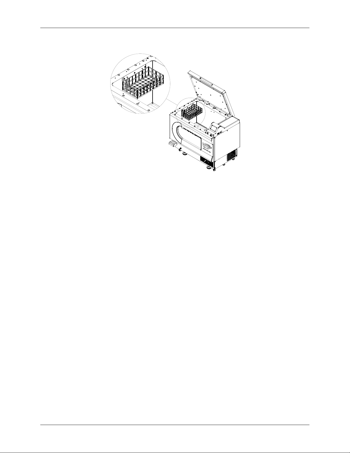
67
Figure 32: Utility Basket (optional)
9.11.10 Optional Remote Alarm
The Innova 43/43R can be equipped with a factory-installed remote alarm
component (part number M1320-8029). When it is hooked up to your relay and
receiving requipment, this device will send notification of an alarm condition to
the remote location you choose.
New Brunswick Operating manual
Page 68
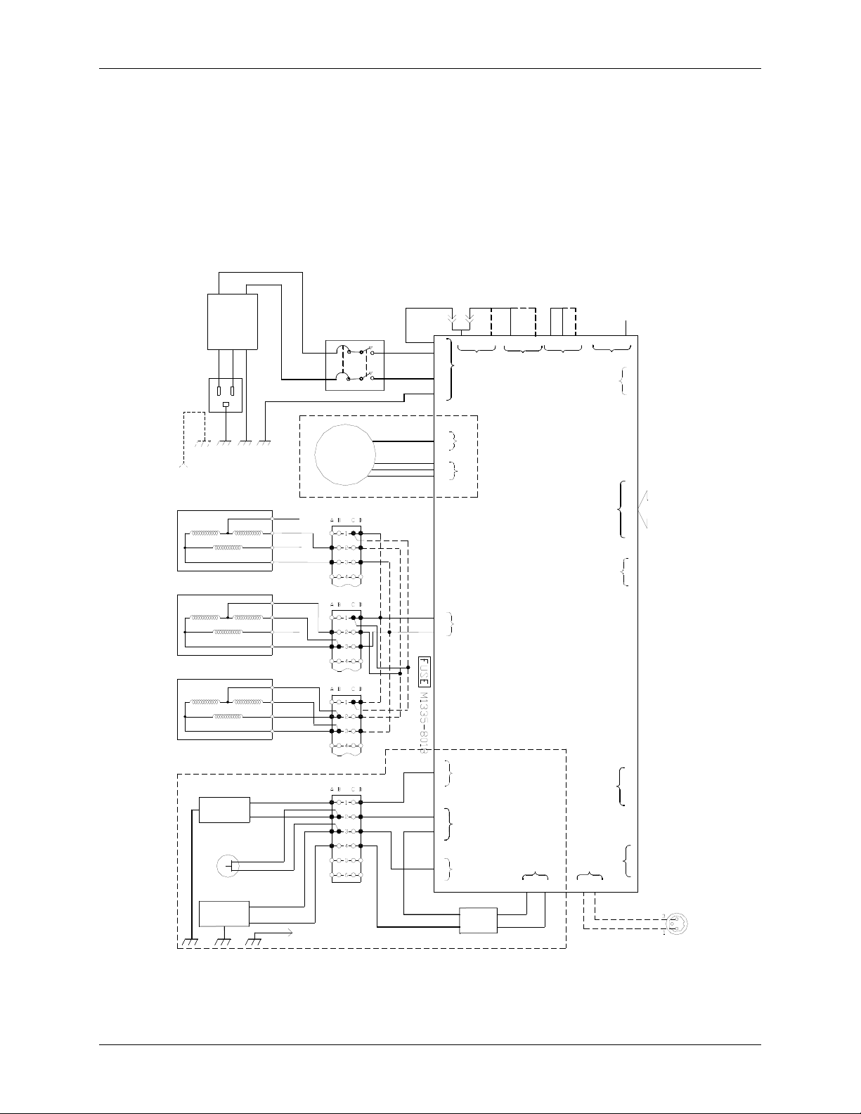
68
0
110
D
D
10.1 Schematics
Figure 33a: Control Schematics (left side)
L
N
load
Filter
AC POWER
ENTRY
100-230 VAC
FROM REFRIG
GND STUD
HEATER 230Vac OPERATION
HEATER 120Vac OPERATION
LF1
line
G
N
L
MAIN GND STUD
M1320-8013
M1320-8016
RED
BLACK
WHITE
YELLOW
RED
BLACK
WHITE
YELLOW
WIINNGGSS
RRAAW
CB001
15 AMP
21
11 12
M1335-8000
POWER
TRANSFORMER
ONLY FOR
230V & 100V
INPUT LINE
I43R REFRIGERATION UNIT
(OPTIONAL)
TB001
TB001
22
M1320-8013
RED
WHITE
LINE INPUT
JUMPER
230V
120V
100V
N
RED
M1320-8004
WHITE
INSTALL
P0380-5980
2
L
N
4
G
6
1
6
1
2
5
3
1
,
G
,
M1335-8002
J9
RRAAPPHHSS
G
LINE INPUT
VOLTAGE SELECT
230V
3
1
J25
J22
J20
POWER DISTRIBUTION
J17
120V
2
J21
BOARD
M1282-7011
50/60 SELECT
60HZ
(100V)
(120V)
100V
13
5
J13
&
T
&
50HZ
(100V)
(230V)
LN
G
53
5
1
J12
J11
J18
J14
J1-12
AABBLLEES
T
1
6
2
3
S
HEATER 100Vac OPERATION
I43R REFRIGERATION UNIT
(OPTIONAL)
COND. FAN
1
OVER PRESSURE SWITCH
Comp.Unit
REFRIGERATIO N GND STUD
1
2
3
RED
BLACK
WHITE
YELLOW
TO MAIN GND STUD
BLU
BLK
ORG
BLK
TB001
RED
WHITE
J7-2 (+30V)
3
J21
LOW PWR.
M1335-8007
FAN
N
1
J5
L
3
AC
J6
1
1
EXT.
A
C
2
SSR
J8
2
+5V
3
+
4
M1320-8021
1
4
GND
TB002
BLU
ORG
BLK
VIO
BLK
VIO
1
N
3
4
L
1
3
J3
J19
4
3
M1320-8027
Alarm Option
Innova 43 & 43R Incubator Shakers M1320-0050 Operating manual
Page 69
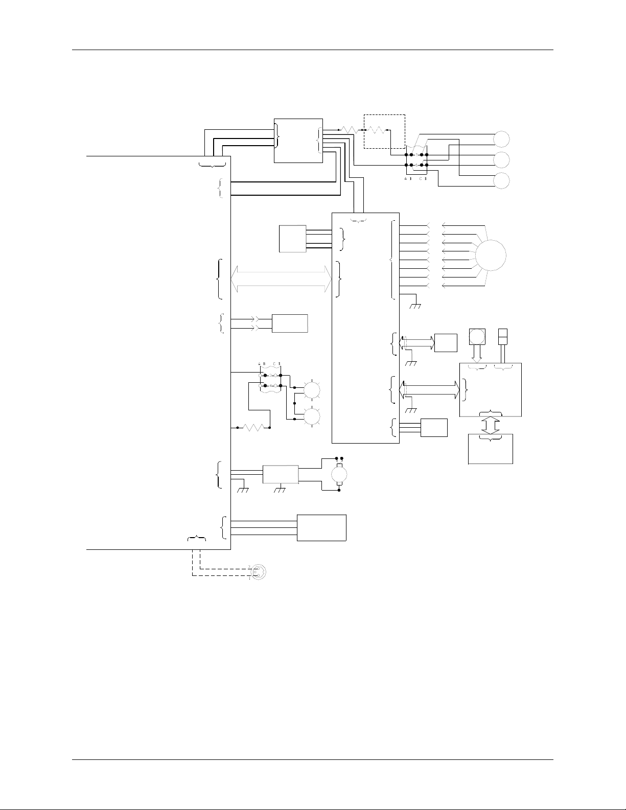
69
Figure 33b: Control Schematics (right side)
R1
POWER DISTRIBUTION
BOARD
M1282-7011
LN
53
J12
J11
J14
J7-2 (+30V)
J4
G
J1-12
1
M1320-8000
BRN
1
6
PNK
2
3
M1320-8022
120V
1
N
3
GND
4
M1320-8033
R2
5 ohm, 25W
BLK
WHT
5
3
CN1
1
POWER SUPPLY
P0460-3330
Temp.
Sensor,RTD
50 Cond. Ribbon Cable
M1320-8020
Door
Switch
TB001
M1320-8011
M1320-8010
UV
BALLAST
(OPTIONAL)
CN2
LAMP
1
M1320-8024
LAMP
2
BLUE
RED
3
12
2
11
1
10
5 ohm, 25W
1
2
3
4
UV
LAMP
J5J18
CONTROL BOARD
BRN
J6A J6B
J6
J7
M1282-7012
R2
7.5 ohm, 25W
(ONLY NON-REFIG.)
(M1320-8032)
PNK
M1282-8019
PNK
BRN
TB001
M1320-8031
3
4
5
6
7
J1
8
9
10
1
M1320-8006
10 Cond.
J3
Ribbon Cable
M1320-8007
J4
14 Cond.
Ribbon Cable
P1-1
P1-2
P1-3
P1-4
P1-5
P1-6
P1-7
P1-8
RS232
Port
PHASE C
PHASE B
PHASE A
GND
VREF
SA
SB
SC
M1282-5010
+
PINK
FAN 1
BRN
+
PINK
FAN 2
BRN
+
PINK
FAN 3
BRN
1
2
3
4
MTR
5
M001
6
7
8
ENCODER
P0400-1911
SWITCH ROTARY
1
J3
DISPLAY BOARD
J7
M1282-7010
M1320-8017
SWITCH ASSY
PUSH BUTTON
START
STOP
2
J4
J6
+5V
GND
Humidity
Sensor
(OPTIONAL)
M1320-8006
CN1
Display
LCD
M1320-8025
M1282-8016
1
2
J8
3
L
J19
1
3
4
M1320-8027
GND
M1282-5046
Alarm Option
1
N
3
J3
PHOTOSYNTHETIC
LIGHT BANK
M1282-5046
(OPTIONAL)
New Brunswick Operating manual
Page 70
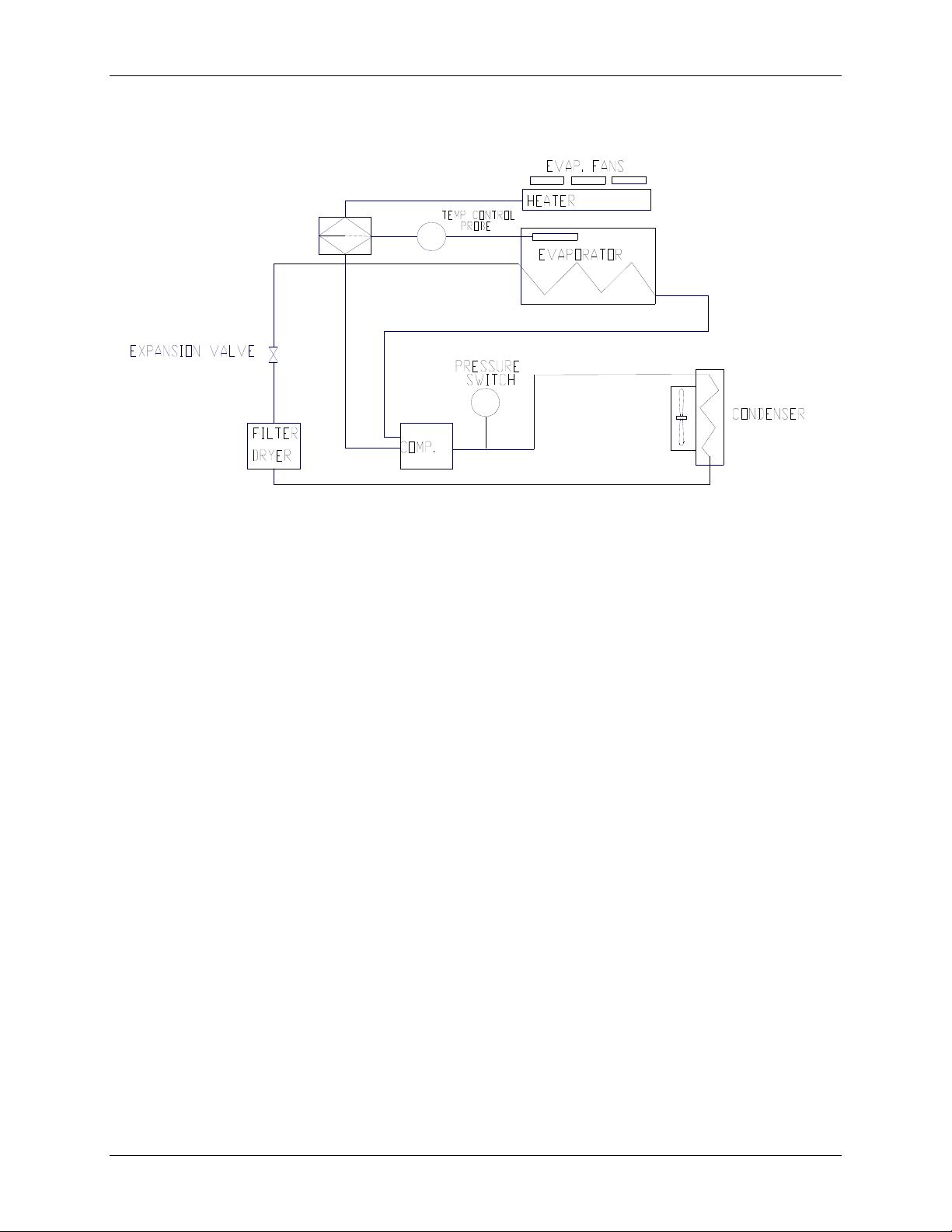
70
Figure 34: Refrigeration Schematic
10.2 Load & Speed Graphs
The following graphs explain the maximum recommended shaking speed according to
the load you put on your shaker’s platform and the diameter of the shaker’s orbit (1-inch
or 2-inch).
Innova 43 & 43R Incubator Shakers M1320-0050 Operating manual
Page 71

71
0
Figure 35: Load & Speed for 1-Inch Orbit Shakers
(20% Full)
500
450
400
350
300
250
200
150
Maximum Recommended RPM
100
50
0
300
250
200
50, 125,
250, 50
mL
1L,
2.8L
2L,
4L,
6L
<20 20 to 30 30 to 36 36 to 40 40 to 50 50 to 60 >60
Platform and Load (lb)
Figure 36: Load & Speed for 2-Inch Orbit Shakers
(20% Full)
150
50,
125,
250,
500 mL
1L,
2.8L
2L,
4L,
6L
100
Maximum Recommended RPM
50
0
<20 20 to 30 30 to 36 36 to 40 40 to 50 50 to 60 >60
Platform and Load (lb)
New Brunswick Operating manual
Page 72

72
1
S
111
PPEECCIIFFIICCAATTIIOONNS
S
These specifications assume a maximum load of 34 pounds (15.5 kg), including platforms,
clamps, glassware and contents.
Innova 43 & 43R Incubator Shaker
SHAKING
Speed
Control Accuracy
Indication
Stroke/Orbit
TEMPERATURE
Range (43)
Range (43R)
Control Accuracy
Uniformity
Indication
Heater
ALARMS
LCD DISPLAY
RS-232
SETPOINT RETENTION
AUTOMATIC RESTART
DRIVE
DRIVE MOTOR
SAFETY
ELECTRICAL
REQUIREMENTS
ETL REGULATORY
STANDARDS
CE REGULATORY
STANDARDS
DIMENSIONS3
Width
Depth (Front to Back)
Height
1
see first NOTE on following page
2
depending on ambient factors, such as relative humidity, and options installed
3
see second NOTE on following page
1
20-500 rpm with 1-inch (2.5 cm) stroke or 20-300 rpm with 2-inch (5.1 cm)
stroke
1 rpm
Displayed in 1 rpm increments
1-inch (2.5 cm) or 2-inch (5.1 cm)
5ºC above ambient temperature to 80°C
20ºC below ambient temperature (minimum 4ºC) to 80°C
0.1°C from 30-40 °C, 0.5°C over the remaining range.
0.25°C in flask across platform at 37ºC, and 0. 5°C (or less) at 60ºC
Displayed in 0.1°C increments
Long-life, low-watt density resistance-type heater with high temperature
thermostat
Visible and audible warning indication when speed deviates more than 5
rpm or temperature more than 1°C from setpoints, and when timer has
expired. Audible alarm can be muted.
240 x 128 backlit
Remote control, remote monitoring, remote data logging
All setpoints and operating status are retained in non-volatile memory
Automatic restart after power is restored, indicated by flashing display
Triple-eccentric counterbalanced drive with nine permanently lubricated ball
bearings and poly-V belt. Self-calibrating.
Solid-state brushless DC motor.
Drive Interrupt shuts off power to Shaker when lid opens.
Acceleration/deceleration circuit prevents sudden starts and stops,
minimizing both splashing and mechanical damage.
100V, 50Hz
100V, 60 Hz
120 Volts, 60 Hz
230 Volts, 50 Hz
UL 61010A-1 CAN/CSA-C22.2 No. 1010.1
UL 61010A-2-010 CAN/CSA-C22.2 No. 1010.2.010
IEC 61010-1: 2001 2nd ed. EN 61010-2-081 (2002) EN 61000-3-2 : 1995
EN 61010-1: 2001 2nd ed. EN 61326 : 1997 + A1 : 1998
EN 61000-3-3 : 1995 EN 61010-2-010 (1992) + A1: 1996
53 inches (135 cm)
32 inches (81 cm)
40.6 inches (103 cm)
2
43: 800 VA per shaker
43R: 1500 VA per shaker
2
S
Innova 43 & 43R Incubator Shakers M1320-0050 Operating manual
Page 73

73
Innova 43 & 43R Incubator Shaker
CHAMBER
DIMENSIONS
CHAMBER LID
PLATFORM
WEIGHT
43
43R
24 inches deep X 34.5 inches wide X 19 inches high from top of platform
(61 cm deep X 87.6 cm wide X 48 cm high from top of platform)
Foot-activated lid opening.
Aluminum, 18" X 30" (46 X 76 cm). Select universal or dedicated styles
460 lbs (209 kg)
510 lbs (231 kg)
NOTE:
Use of baffled flasks will significantly reduce maximum speed for any shaker.
11.1 Certifications
The Innova 43 and 43R have been tested to ETL standards, to comply with UL and
CAN/CSA electrical safety standards (see “ETL Regulatory Standards” in the
specifications table).
As attested in the CE Declaration of Conformity reproduced on the following page, the
Innova 43 and 43R also conform to the appropriate CE standards (see also “CE
Regulatory Standards” in the specifications table).
New Brunswick Operating manual
Page 74

74
11.1.1 CE Declaration of Conformity
Innova 43 & 43R Incubator Shakers M1320-0050 Operating manual
Page 75

75
2
A
112
12.1 Setting Up with HyperTerminal
You can use the Microsoft® HyperTerminal program on your personal computer to
communicate with your shaker:
1. Before you set up HyperTerminal, be sure to check the Mode and Baud Rate
parameter settings (see Section 7.4.5).
2. While you are in the RS232 screen (see Figure 15), set the
and select the appropriate
is 19200; your other choices are 9600 or 38400.
3. Connect the RS-232 cable between your computer and the shaker’s RS-232 port (see
Figure 4).
4. Start HyperTerminal, and follow the steps for Setting a New Connection. When
prompted, select the COM port you will be using, then set the COM parameters (see
Table 17 below):
5. To be sure that you have established a connection with your shaker, turn the shaker
OFF, open the HyperTerminal connection, then turn the shaker back ON. Once a
connection has been made, the shaker will send an OK to HyperTerminal.
6. You may wish to send a trial command to the shaker (see Sample Test below). We
suggest that you enable Caps Lock on your computer, because all commands must be
sent as capital letters.
Sample Test:
1. To request the current setpoint, type RS at the terminal. When you type R, you
should see the
Innova 43/43R. When you type the S, you should see the echo S displayed at the
computer.
2. Use the
cursor back over the first character.
3.
RS is a Request command, so your shaker will send back the data corresponding to
the command.
PPPPEENNDDIIX
A
Table 17: COM Parameters for HyperTerminal
Baud Rate
Data Bits
Parity
Stop Bits
Flow Control
R on the computer display. This is an echo character, sent back by the
Enter key to send the carriage return control character. This will move the
X
:
R
:
R
Baud Rate. The default setting, as you see in your screen,
Enter the setting on your shaker
(see Step 2 above)
8
None
1
None
EEMMOOTTEE
P
RROOGGRRAAMMMMIINNG
P
Mode parameter to Slave,
G
New Brunswick Operating manual
Page 76

76
12.2 Overview of Command Sets
Using an optional RS-232 interface, the user has the capability to control various
functions of the Innova 43/43R shakers by computer. A detailed command set follows
this introduction.
The serial interface uses an echo character protocol that is implemented to indicate that a
valid character has been received by the shaker. For every character sent by the user
computer, the Innova 43/43R will return a matching character. This echo character
should be read by the computer and compared to the character that was sent.
NOTE:
When you are sending a command, do not allow the pause between any two
characters of your message to last longer than 10 seconds. If it takes any
longer, the shaker’s serial port will reset itself.
In the following example, the Master (your computer) will command (the C in CS) the
shaker (Slave) to set its speed to 150 RPM:
Master sends: Innova 43/43R responds:
CS<Space>150<CR> CS<Space>150<CR>
In the next example, the Master (your computer) will request that the shaker (Slave)
report (the R in RV) the actual parameters:
Master sends: Innova 43/43R responds:
RV<CR> First the echo: RV<CR>
Then the report:
<Arg1><Tab><Arg2><Tab><Arg3>...<Arg7><CR><LF>
NOTE:
On power-up, even if the shaker is not set in
shaker will always send these four characters:
Slave mode at the time, the
OK<CR><LF>. Before
starting any communications, be sure to clear the computer’s receive buffer.
This is the command set format:
<Command><Space><Arg1><Space><Argn…><Terminator>
Most Commands are defined as two capital characters using standard ASCII format (see
the command sets provided below).
If a command has additional arguments, the ASCII space control character separates each
argument. The command is terminated using the ASCII carriage return control character;
Innova 43 & 43R Incubator Shakers M1320-0050 Operating manual
Page 77

77
an optional line feed control character may also be included but must follow the carriage
return character.
When a command is sent that returns data, the characters returned are in ASCII format.
Each additional argument returned will be separated by the ASCII space or tab control
character; refer to the selected command for the actual format. Data returned is
terminated with a carriage return line feed control character sequence.
Section 12.3 provides an Index to the 2-character command codes.
Sections 12.4-12.7 provide command sets for your use for Set Commands, Profile
Control Commands, Report Request Commands and Set/Get Date & Time.
12.3 Index to Command Codes
Command Code Meaning
CL Command Grow Lamp
CS Command Speed
CT Command Temperature
CU Command UV Lamp
PC Clear Profile
PM Profile Mode
PR Read Profile Step in Memory
PS Profile Stop/Start
PW Write Profile Step to Memory
RI Report Software Version
RP Report Parameter List
RS Report Setpoint Values
RV Report Measured Values
=D Set Date and Time
?D Get Date and Time
New Brunswick Operating manual
Page 78

78
12.4 Set Commands
Code Meaning Format
CL Command Grow
Lamp
CS Command Speed
CT Command
Temperature
CU Command UV
Lamp
12.5 Profile Control Commands
Code Meaning Format
PC Clear Profile
(clears profile
step)
PM Profile Mode
(returns status of
current profile
run/hold mode)
PC<Space><Arg1><Space><Arg2><CR>
where Arg1= Profile number (range 1 to 4) and
Arg2=Step number (range 1 to 15)
NOTE: If Arg2 is not included, all 15 steps of the
selected profile will be cleared.
PM<CR>
There are no parameters to this command.
Return data format:
<Arg1><Space><Arg2><Space><Arg3><CR>
where Arg1=Run/hold status (0 = end, 1 = run),
Arg2=Profile number and
Arg3=Step number
NOTE: If a profile has not been selected to run, a 0
will be returned for Profile number and Step number.
...continued...
CL<Space><Arg1><CR>
where Arg1= Set Grow Lamp state (0 = off, 1 = on)
CS<Space><Arg1><CR>
where Arg1= Agitation setpoint (####)
CT<Space><Arg1><CR>
where Arg1= Temperature setpoint (###.#)
CU<Space><Arg1><CR>
where Arg1= Set UV Lamp state (0 = off, 1 = on)
Innova 43 & 43R Incubator Shakers M1320-0050 Operating manual
Page 79

79
Code Meaning Format
PR Read
Profile
step in
memory
PS Profile
Stop/
Start
(stops or
starts a
program
profile)
PW Write
Profile
step to
memory
PR<Space><Arg1><Space><Arg2><CR>
where Arg1= Profile number (range 1 to 4) and
Arg2=Step number (range 1 to 15)
Return data format:
<Arg1><Space><Arg2><Space><Arg3><Space>...<CR><LF>
where Arg1=Profile number (range 1 to 4),
Arg2=Step number,
Arg3=Temperature setpoint,
Arg4=Agitation setpoint,
Arg5=(Reserved, reads 0.0),
Arg6=Step hours,
Arg7=Step minutes,
Arg8=UV lamp, and
Arg9=Grow lamp
PS<CR>
With no other parameters, any profile currently running will be
stopped.
PS<Space><Arg1><Space><Arg2><CR>
where Arg1=Profile number (range 1 to 4), and
Arg2=Step number (range 1 to 15).
NOTE: If Arg2 is not included, the profile will start in Step 1.
PW<Space><Arg1><Space><Arg2><Space><Arg3><Space>
...<CR>
where Arg1=Profile number (range 1 to 4),
Arg2=Step number (range 1 to 15),
Arg3=Temperature setpoint,
Arg4=Agitation setpoint,
Arg5=(Reserved); Enter 0.0,
Arg6=Step hours (range 0 to 99),
Arg7=Step minutes (range 0 to 59),
Arg8=UV lamp (0 = off, 1 = on), and
Arg9=Grow lamp (0 = off, 1 = on)
For example, the following PW command:
PW<Space>25.0<Space>150<Space>0.0<Space>2<Space>30<Space>0
<Space>1<CR>
will set Program 1, Step 1 to the following conditions:
Temperature setpoint 25.0º Step Time 2 hours 30 minutes
Agitation setpoint 150 rpm UV Lamp OFF
GRO Lamp ON
New Brunswick Operating manual
Page 80

80
12.6 Report Request Commands
Code Meaning Format
RI Report
Software
Version
RP Report
Parameter
List (ASCII
text header)
Report
Measured
Values
Report
Setpoint
RV
RS
Values
RI<CR>
Return data format:
<Arg1><Tab><Arg2><CR><LF>
where Arg1=Display module software version, and
Arg2=Control module software version
RP<CR>
Return data format:
<Arg1><Tab><Arg2><Tab><Arg3>...<Arg6><CR><LF>
where Arg1=”Shaker Speed”,
Arg2=”Temperature”,
Arg3=”% Relative Humidity”,
Arg4=”Reserved”,
Arg5=”Grow Lamp Status”, and
Arg6=”UV Lamp Status”
RV<CR>
RS<CR>
Return data format:
<Arg1><Tab><Arg2><Tab><Arg3>...<Arg6><CR><LF>
where Arg1= Shaker Speed,
Arg2=Temperature,
Arg3=% Relative Humidity,
Arg4=(Reserved, reads 0.0),
Arg5=Grow Lamp Status, and
Arg6=UV Lamp Status
Innova 43 & 43R Incubator Shakers M1320-0050 Operating manual
Page 81

81
12.7 Set/Get Date & Time
Code Meaning Format
Set Date
& Time
Get Date
& Time
=D<Space><Arg1><Space><Arg2><Space><Arg3><Space>...
<Arg7><CR>
?D<CR>
Return data format:
<Arg1><Tab><Arg2><Tab><Arg3><Tab>...<Arg7><CR><LF>
where Arg1=Hours (range 0-23),
Arg2=Minutes (range 0-59),
Arg3=Seconds (range 0-59),
Arg4=Year (range 00-99),
Arg5=Month (range 01-12),
Arg6=Date (range 1-31),
Arg7=Day (range 1-7; 1=Monday, 2=Tuesday...7=Sunday)
=D
?D
For example, this =D command:
=D<Space><01><Space><30><Space><00><Space><04><Space><07>
<Space><04><Space><07><CR>
will set the real date and time on your shaker to:
1:30:00 am, 2004, July 4, Sunday.
New Brunswick Operating manual
Page 82

82
A
Accessories, 63
Racks & Trays, 65
Actual Temperature, 47
Adjusting Lid Tension, 58
Alarms, 7, 18, 72
Arrows Icon, 17
ASCII Format, 76
ASCII Text Headers, 80
Audible Alarm
Disabling, 46
Audible Alarm Muted Icon, 16
Audible Alarms, 18
Automatic Restart, 49, 72
B
Baud Rate
Setting the, 39
Belt Replacement, 60
Biohazards, 50
C
Calibrate Screen, 40
Calibrating RPM, 48
Calspeed, 48
Chamber Light
Auto, 38
On/Off, 37
Changing a Setpoint, 35
Changing Baud Rate, 40
Changing Communication Mode, 39
Changing Screens, 34
Changing the Day, 36
Changing the Time, 37
Clamp Hardware Kits, 65
Clearance, 11
COM Parameters, 75
COMM Screen, 39
3
113
Command Codes, 76
Command Format, 76
Communication Mode, 40
Continuous Operation, 7
Control Knob, 16
Creating a Program, 42
Customer Satisfaction Form 6300, 9
D
Day, 36
Declaration of Conformity, 74
Decontamination, 50
Dimensions
Chamber, 72
Overall, 72
Display Icons, 17
Display Parameters, 16
Display Screen, 32
Changing Parameters, 32
Modifying Setpoints, 33
Display Screens
Changing the, 16
Door
Opening the, 31
Door Open Icon, 16, 17, 32
Drive, 72
Drive Belt
Removing the, 60
Replacing the, 60
E
Edit Program, 46
Electrical Requirements, 10, 72
Environment, 10
F
Firmware
Operation via, 7
Flask Capacities, 64
I
NNDDEEX
I
X
Innova 43 & 43R Incubator Shakers M1320-0050 Operating manual
Page 83

83
Flask Clamps, 64
Installation of, 22
Front View, 11
Fuses, 55
G
Gas Manifold Kit, 24, 66
Germicidal Lamp, 66
Glide-Up Door, 19
Growth
On/Off, 37
Growth Lamps, 66
H
Heater, 20, 72
Heater On Icon, 16, 17
HRS Alarm, 19
Humidity Monitor, 19, 66
HyperTerminal, 75
I
Icons, 17
Incomplete Order, 9
Indicated Temperature, 47
Inspection
Of Boxes, 9
Installing Flask Clamps, 22
Interior Light, 20
L
LAMP, 20
Lamps Screen, 37
LCD Display, 16, 72
Leveling
One Shaker, No Base, 13
Lid Tension
Adjusting the, 58
Load & Speed Graphs, 70
Locked Icon, 17
Locking Settings, 37
Loudspeaker Icon, 17, 37
M
Missing Parts, 9
Modifying a Setpoint, 33, 35
Monitor Mode, 40
Motor, 72
Moving Screen to Screen, 34
Mute, 37, 46
Mute Icon, 16, 17
Muting the Alarm, 37
N
Narrow Doorway, 11
New Program, 42
O
Operation Modes, 7
Overview, 7
P
Packing List
Verification of, 9
Padlock Icon, 17, 37
Parameter Locked Icon, 16
Photosynthetic Lamps, 20, 26, 27, 66
Platform
Available Types, 63
Platform Assemblies, 22
Platform Screw Locations, 22
Platforms, 8
POWER Alarm, 19
Power Failure, 49
Power Interruption, 49
Problems, 52
Product Returns, 54
Program Running Icon, 17
Programming, 42
Programs Screen, 41
R
Refrigeration, 20
Refrigeration Schematic, 70
Remote Alarm Option, 67
Remote Programming, 76
Replacement Parts, 63
Replacing UV Light, 59
Report Request Commands, 80
Resetting the Day, 36
New Brunswick Operating manual
Page 84

84
Resetting the Time, 37
Returned Material Authorization Number,
54
Returned Material Safety Sheet, 54
RMA, 54
RS-232, 20, 72, 76
RS-232 Interface
Operation via, 7
RS232 Screen, 39
Run Icon, 16, 17, 46
S
Safety, 72
Safety Precautions, 31
Safety Switch, 7
Sample Program Screen, 45
Save Program, 45
Screen Parameters, 17
Service Accessibility, 21
Set Commands, 78
Setpoint Retention, 72
Setting the Baud Rate, 39
Setup Screen, 36
Changing the Day, 36
Changing the Time, 37
Locking Settings, 37
Muting the Alarm, 37
Shaking Speed, 72
Shipping Damage, 9
Slave Mode, 40
Software Interface, 20
Space Requirements, 11
Specifications, 72
SPEED Alarm, 19
Spill Pan, 19
Filling the, 29
Spills, 50
Summary Screen, 35
Changing Setpoints, 35
Symptoms, 52
T
Talk Mode, 40
TEMP Alarm, 19
Temperature Offset, 41, 47, 48
Setting the, 47
Temperature Offset Calibration, 47
Temperature Offset Value, 47
Temperature Range, 72
Test Tube Racks, 65
Time, 37
Timed Functions, 42
Timed Run, 7
Troubleshooting, 52
U
Unpacking
Tools for, 9
Utility Basket, 66
UV Decont
On/Off, 37
UV Lamp, 20, 66
V
Visible Alarms, 18
W
Warranty, 3
Water Reservoir, 19
Filling the, 29
Wavy Arrows Icon, 17
Innova 43 & 43R Incubator Shakers M1320-0050 Operating manual
Page 85

85
New Brunswick Operating manual
Page 86

Evaluate your manual
Give us your feedback.
www.eppendorf.com/manualfeedback
Your local distributor: www.eppendorf.com/worldwide
Eppendorf AG · Hamburg · Germany · Tel: +49 40 538 01-0
Application Support E-mail: support@eppendorf.com
Eppendorf North America, Inc. · USA · Tel: +1 516 334 7500
Toll free phone: +1 800 645 3050 menu option 2
E-mail: techserv@eppendorf.com
www.eppendorf.com
 Loading...