

Page 1
Page 2

ii
Copyright
Copyright © 2012-2013 Eppendorf AG, Hamburg. Nor part of this publication may be
reproduced without the prior permission of t he copyrig ht owner.
The company reserves the right to chang e information in this document without notice.
Updates to information in this document reflect our commitment to continuing product
development and improvement.
Trademarks
Eppendorf
®
and the Eppendorf logo are r egistered trademarks of Eppendorf AG,
Germany.
Innova
®
is a registered trademark of New Brunswick Scientific Co ., Inc., USA.
New Brunswick™
and the New Brunswick™ logo are trademarks of Eppendorf AG,
Germany.
Trademarks are not m ar ked in all cases with ™ or ® in this manual.
Eppendorf has attempted t o ident ify the ownership of all trademarks f r om public records. Any
omissions or errors are unintentional.
June 06, 2013
Revision M
M1231-0050
Page 3
iii
CAUTION! Risk of damage to personnel and/or equipment!
This equipment must be operated as described in t his manual.
Please read the entire operating m anual before attempting to use this equi pm ent .
If operational guidelines ar e not f ollowed, equipment dam age and per sonal injury
can occur.
Do not use this equipment in a hazardous atmosphere or with hazardous
materials for which the equipment was not designed.
New Brunswi ck Sci ent i f ic Co., Inc. is not responsible f or any damage to thi s
equipment that may result from the use of an accessory not manufactur ed by New
Brunswick.
Innova 3100 M1231-0050 Operating manual
Page 4

iv
TABLE OF CONTENTS
1 INTRODUCTION ....................................................................................................................................... 1
2 OVERVIEW & FEATURES ...................................................................................................................... 2
2.1 GENERAL DESCRIPTION ............................................................................................................................. 2
2.2 UNIVERSAL POWER CAPABILITY ................................................................................................................ 4
2.3 CONTROL PANEL ....................................................................................................................................... 5
2.3.1 LED Display .................................................................................................................................... 5
2.3.2 User Interface Keys ......................................................................................................................... 6
2.3.3 Status Indicator Lights .................................................................................................................... 6
2.3.4 Function Indicator Lights ................................................................................................................ 7
2.4 PLATFORM ASSEMBLIES ............................................................................................................................ 7
2.5 COOLING COIL OPTION .............................................................................................................................. 7
2.6 ACCESSORIES & OPTIONS .......................................................................................................................... 7
2.7 TRIPLE ECCENTRIC DRIVE ......................................................................................................................... 8
2.8 BEARINGS .................................................................................................................................................. 9
2.9 MOTOR ...................................................................................................................................................... 9
2.10 ELECTRONIC BOARDS ........................................................................................................................... 9
3 INSTALLATION & SET-UP ................................................................................................................... 10
3.1 UNPACKING & INSPECTION ...................................................................................................................... 10
3.2 VOLTAGE CONFIGURATION ...................................................................................................................... 10
3.3 INSTALLATION ......................................................................................................................................... 11
3.3.1 Space Requirements ...................................................................................................................... 11
3.3.2 Hose Connections .......................................................................................................................... 12
3.3.3 Platform Installation ..................................................................................................................... 14
3.3.4 Electrical Connections .................................................................................................................. 15
4 OPERATION ............................................................................................................................................. 16
4.1 STARTING THE INNOVA 3100 ................................................................................................................... 16
4.2 CONTINUOUS (UNLIMITED) RUN .............................................................................................................. 16
4.3 CHECKING A SETPOINT ............................................................................................................................ 17
4.4 TIMED FUNCTIONS ................................................................................................................................... 17
4.4.1 Setting the Timer ........................................................................................................................... 17
4.4.2 Cancelling the Timer ..................................................................................................................... 18
4.5 ALARM FUNCTIONS ................................................................................................................................. 18
4.6 TEMPERATURE ......................................................................................................................................... 18
4.6.1 Setting the Temperature ................................................................................................................ 18
4.6.2 Deactivating Temperature Control ............................................................................................... 19
4.7 TEMPERATURE OFFSET CALIBRATION ..................................................................................................... 19
4.8 TOTAL RUNNING TIME ............................................................................................................................. 20
4.9 MAINT INDICATOR LIGHT ...................................................................................................................... 21
4.10 WATER LEVEL CONTROL .................................................................................................................... 21
4.11 LOW WATER LEVEL ALARM ............................................................................................................... 22
4.12 DRAINING THE BATH ........................................................................................................................... 22
5 MAINTENANCE & SERVICE ................................................................................................................ 23
5.1 MAINTENANCE ........................................................................................................................................ 23
5.2 CLEANING ................................................................................................................................................ 23
5.3 CHANGING FUSES .................................................................................................................................... 24
5.4 CHANGING VOLTAGE ............................................................................................................................... 24
Page 5

v
5.5 REPLACING/ADJUSTING THE MOTOR DRIVE BELT ................................................................................... 25
5.6 REPLACING THE MOTOR ASSEMBLY ........................................................................................................ 26
5.7 ACKNOWLEDGING THE MAINT INDICATOR ............................................................................................. 27
5.8 RECORDER ADAPTATION ......................................................................................................................... 27
5.9 RETROFITTING THE COOLING COIL OPTION .............................................................................................. 28
5.10 ESD PRECAUTIONS ............................................................................................................................. 30
5.11 REPLACING THE MAIN CONTROL BOARD ............................................................................................ 31
5.12 REPLACING THE TEMPERATURE CONTROL BOARD ............................................................................. 33
5.13 SERVICE PARTS LIST ........................................................................................................................... 34
6 SPECIFICATIONS ................................................................................................................................... 35
7 ACCESSORIES ......................................................................................................................................... 38
7.1 INTERCHANGEABLE PLATFORMS ............................................................................................................. 38
7.2 INTERCHANGEABLE HALF-SIZE PLATFORMS ............................................................................................ 38
7.3 TEST TUBE RACKS FOR SUBPLATFORM.................................................................................................... 39
7.4 ACCESSORIES ........................................................................................................................................... 39
7.5 ACCESSORY FLASK CLAMPS .................................................................................................................... 39
7.6 CLAMP MOUNTING HARDWARE ............................................................................................................... 40
7.6.1 Hardware for 10 mL to 500 mL Clamps........................................................................................ 40
7.6.2 Hardware for 1-Liter to 6-Liter Clamps ........................................................................................ 40
8 DRAWINGS ............................................................................................................................................... 41
8.1 INDEX OF DRAWINGS ............................................................................................................................... 41
9 INDEX ........................................................................................................................................................ 42
Innova 3100 M1231-0050 Operating manual
Page 6

Page 7

1
11
This Manual is intended to provide the user with a complete understanding of
how the Innova 3100 Digital Water Bath Shaker operates, its basic components,
and information about preventive maintenance and service issues. This manual
also includes a complete guide to the installation and operation of the Innova
3100.
The manual is divided into three basic sections. Chapters 1-2 provide an
overview of the Innova 3100, with all of its features and options. Chapters 3-4
detail the set-up, installation and operation of the instrument. Chapter 5 outlines
troubleshooting and service procedures which should be utilized only by a
qualified service engineer. Chapters 6-9 provide additional details of interest:
specifications, lists of accessories and drawings. Finally, Chapter 10 is an index
to important terms used in the manual.
It is recommended that you completely familiarize yourself with this manual,
prior to actually operating the Innova 3100.
The Innova 3100 Digital Water Bath Shaker will provide you with reliable and maintenancefree operation which is characteristic of all NBS shakers. The Innova 3100 is among the
newest generation of NBS shakers and incorporates a variety of state-of-the-art components
and features to permit the precision operation necessary for your exacting scientific
experiments.
I
NNTTRROODDUUCCTTIIOON
I
N
Innova 3100 M1231-0050 Operating manual
Page 8

2
22
2.1 General Description
The Innova 3100 is a shaker that incorporates a triple eccentric counterbalanced drive
to provide horizontal plane rotary motion in a ½ inch (12.7 mm) circular orbit. A
Proportional/Integral (PI) microprocessor controller with instantaneous digital
feedback controls the speed over a range of 25-400 RPM. It also provides temperature
control over a range of 5°C above ambient to 80°C. For lower temperatures an
optional water bath cooling coil is available.
The shaker may be operated either continuously or in a timed mode via a
programmable timer for shaking periods of 0.1 hour to 99.9 hours.
The Innova 3100 is equipped with audible and visible alarms which are activated when
an alarm condition exists as follows:
• The end of a timed run
• Deviations of shaking speed or temperature outside of tolerance limits
• Low water level
• Water overflow
A wide variety of platforms can be used with the Innova 3100. Dedicated platforms
are available for a variety of flask sizes. A Universal platform and test tube racks are
also available. (See Chapter 7 for accessories.)
The Innova 3100 has a built-in water level control system which is infinitely adjustable
over a wide range. To compensate for evaporation, water is automatically replenished
to the preset level.
Additionally, the Innova 3100 has analog outputs for a chart recorder that will record
speed and/or temperature. See Chapter 5 for recorder adaptation.
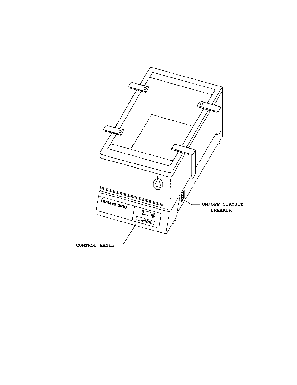
See Figures 1 and 2 below for the front and rear views of the Innova 3100.
O
VVEERRVVIIEEWW
O
&
&
F
EEAATTUURREES
F
S
Page 9
3
Figure 1: Front View
Innova 3100 M1231-0050 Operating manual
Page 10

4
Figure 2: Rear View
2.2 Universal Power Capability
A voltage selector switch is used to select the appropriate voltage. This universal
system adapts to worldwide power requirements. Voltage has been set prior to
shipment. Innova shakers are available in 100V, 120V, 220V and 240V versions, and
accommodate both 50 and 60 Hz frequencies.
WARNING!
It is critical that you check the voltage settings before
you plug the unit into a power source. See S ection 3.2.
Page 11

5
2.3 Control Panel
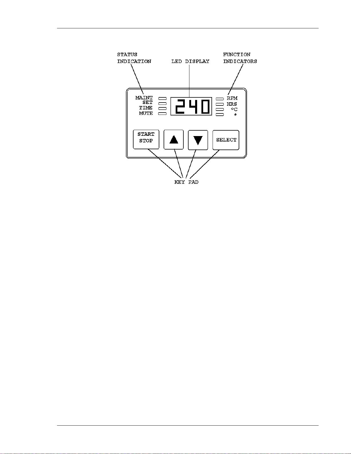
The control panel (see Figure 3 below) is located on the front of the instrument. It serves as
the operator interface. The keypad has four keys marked START/STOP, ∆, ∇, and
SELECT. A three-digit LED display provides numeric values as well as some letter codes.
There are four function indicators and four status indicator lights on the control panel as
well. A general description of the display, user interface keys and indicators follows.
For operation of the control panel, see Chapter 4.
2.3.1 LED Display
The Innova control panel has a 3-digit LED display. During normal shaker
operation, the display will indicate:
• Shaker status (on/off)
• Shaking speed
• Setpoints
• Hours remaining (timed run)
• Measured temperature
• Low water level
Innova 3100 M1231-0050 Operating manual
Page 12
6
•
∆, ∇
Figure 3: Control Panel
2.3.2 User Interface Keys
• START/STOP
This key is used to start or stop the shaking motion. It will also activate or
stop the timer when a timed run is desired.
• SELECT
This key is used to change the displayed parameter.
These keys are used to adjust the setpoint of a displayed parameter up or
down. They also allow the user to enter the SET mode for setpoint
changes.
2.3.3 Status Indicator Lights
There are four status indicator lights, located to the left of the LED display:
• MAINT
Lights to indicate that 10,000 hours have elapsed since the unit was last
serviced. Accumulated running time is internally monitored and may be
displayed as a guideline.
Page 13

7
• SET
Indicates that the shaker is in the SET mode, that setpoints are being
displayed and that they can be altered.
• TIME
Indicates that the timer is in operation. Innova shakers can be programmed
to run for a preset time from 0.1 hour to 99.9 hours. The timer can be
disengaged to reset without stopping an ongoing run.
• MUTE
Indicates the status of the audible alarm. When the MUTE indicator is
illuminated the audible alarm device is disabled.
2.3.4 Function Indicator Lights
There are four function indicator lights, located to the right of the LED display.
They indicate the current parameter being displayed:
• RPM Revolutions per minute
• HRS Time remaining
• °C Current Temperature
• * Low Water Level
2.4 Platform Assemblies
The Innova 3100 can be used with a wide variety of NBS 12 inch x 16.5 inch
platforms which will accept a variety of clamps for flasks and test tubes. Additionally,
a subplatform is available to adapt half platforms for flasks and test tubes used on the
NBS Model G86 Aqua Therm Water Bath Shaker.
2.5 Cooling Coil Option
The Innova 3100 can be ordered with a cooling coil factory-installed. The cooling coil
provides the ability to operate at temperatures below ambient.
2.6 Accessories & Options
The following accessories are available for use with your Innova 3100:
• Gable Cover (plexiglass or stainless steel).
• Portable cart or space saving dolly.
Innova 3100 M1231-0050 Operating manual
Page 14

8
For operation below ambient temperature, the following kits are available for retrofit
(by an NBS-authorized service technician only):
• Cooling coil kit.
• Coolant Circulating System.
2.7 Triple Eccentric Drive
The Triple Eccentric Drive (see Figure 4 below) used in the Innova Shakers employs
the same proven technology which has driven New Brunswick Scientific’s shakers for
over 30 years.
This drive mechanism utilizes a counterweight system to stabilize the rotary motion
produced during operation. When the workload moves in one direction, opposing
forces are generated to stabilize the shaker. This action will help eliminate the
problem of “walking” which may occur with less precisely balanced instruments.
Vibration is minimized and the life of the unit is extended.
Figure 4: Counterbalanced Drive Mechanism
Page 15

9
2.8 Bearings
Innova shakers employ shielded lubricated ball bearings of the highest quality.
Shielded bearings minimize the generation of airborne particulates which may be
disadvantageous in clean rooms or controlled environment areas. These bearings
require no maintenance.
2.9 Motor
The Innova 3100 Shaker uses a 3-phase brushless ball bearing DC motor. This low
profile motor provides high torque along with quiet, efficient operation and low
maintenance. This motor has a rating of 1/15 horsepower.
2.10 Electronic Boards
The main control board for the Innova shaker has the following functions:
• Non-volatile memory for storage of key parameters during power interruption;
• Speed sensing, electronic commutation, and power control for the brushless DC
drive motor;
• Maintains an elapsed running time clock;
• Contains firmware for shaker control as well as recognition of an expansion
connector for option modules;
• Provides an operator interface via displays, audible alarm, and connection to the
keypad module (keypad buttons and display graphics).
The Temperature Control module for the Innova shaker has the following functions:
• Control of analog power supplies;
• Rectification and regulation for analog power supplies;
• Provides signal conditioning circuitry and A/D conversion for the RTD-based
temperature measurement;
• Provides remote monitoring capabilities by supplying analog output for speed and
temperature which are compatible with chart recorders and analog data acquisition
system;
• Controls the heater.
Innova 3100 M1231-0050 Operating manual
Page 16
10
33
The Innova 3100 is a versatile instrument that can be operated in a
continuous fashion or set for a timed run. The following section
describes set up and installation procedures.
3.1 Unpacking & Inspection
Upon unpacking the unit, inspect it carefully for any apparent damage which may have
occurred during transit. Report any damage to the carrier and to the New Brunswick
Service Department (in the USA, call 1-800-631-5417) or to your New Brunswick
Service Representative. Do not discard the crate or packing material.
3.2 Voltage Configuration
I
NNSSTTAALLLLAATTIIOONN
I
&
&
S
S
T
EET
U
--U
P
P
Determine the voltage of your unit by checking the voltage selector and label on the
rear of the unit. Confirm that the correct electrical service package is included with
the unit by comparing the part number on the electrical service package to the
following table (also see Chapter 5).
In addition to checking the voltage of your unit as indicated in the WARNING above,
be sure to confirm that the correct electrical service package is included with the unit.
Compare the part number on the electrical service package to the following table:
WARNING!
It is critical that you check the voltage settings before
you plug the unit into a power source.
Confirm that the Voltage setting is correct by checking
the voltage setting on the Voltage Selector Switch and
the CAUTION label located over the power cord
connection (see Figure 2).
Page 17

11
Voltage Configuration Table
Innova 3100
Catalog #
Voltage
Electrical Service Package
M1231-0001
100V 50/60Hz
M1195-0350
M1231-0000
120V 50/60Hz
M1195-0350
M1231-0002
220V 50/60Hz
M1195-0360
M1231-0003
240V 50/60Hz
M1195-0360
WARNING!
connections to unplug the device.
NOTE:
Use of the Innova shakers requires a platform, which is a separate item.
Available platforms are listed in Chapter 7.
3.3 Installation
3.3.1 Space Requirements
There should be enough space ar ound the mains/power
It is essential that the instrument be situated in an area where there is sufficient
space for the shaker and service lines (see Figure 5 below).
Figure 5: Space Requirements
The outside dimensions of the Innova 3100 are:
Innova 3100 M1231-0050 Operating manual
Page 18

12
Inches
Centimeters
Width
19½
43.2
Depth
27½
69.9
Height
17
36.8
Inches
Centimeters
Width
21½
48.3
Depth
30
76.2
The effective surface area required for operation is:
3.3.2 Hose Connections
A ½ inch diameter reinforced hose is provided for water addition and drainage.
Cut the hose into two lengths, to suit the distances from the water source to the
machine.
Install the hosing as follows, using Figure 6 on following page for reference:
1. Connect one length of ½ inch hose to the WATER IN FITTING.
2. Connect the other length of ½ inch hose to the DRAIN FITTING.
3. Clamp the hoses with the clamps provided.
4. Connect the “WATER IN” hose to a water supply with a maximum water
pressure of 100 psi. The drain hose must go to an OPEN drain.
5. Attach the smaller diameter (3/8 inch) hose to the overflow tube, and run it
to an OPEN drain.
Page 19

13
Figure 6: Hose Connections
The overflow tube is the farthest left of the three tubes that project down from
the back of the bath. The other two tubes are used only when the cooling coil
option is installed.
NOTE:
To minimize the development of rust inside the waterbath:
• If you are using tap water in the bath, make sure the water has a low
iron content.
• If you are using distilled water, mix it with a small amount of tap
water and/or add dis solved salts. Any ultra-pure (distilled, de-ionized
or reverse osmosis) water tends to leach the iron from the stainless
steel, encouraging oxidation.
If the cooling coil option is factory-installed in your unit, an additional 16foot reinforced rubber hose is provided, with corresponding clamps, for
connection to the coolant or water supply. To install the hose:
1. Cut the hose into two pieces to suit a water supply and drain length
2. Attach each of the two hoses to the cooling coil connection tubes with
3. One line must go to an open drain or return to a coolant supply; the other
requirement.
clamps, allowing 1/8 - 3/16 inch of hose to extend beyond the clamps.
line must be connected to a water or coolant supply.
Innova 3100 M1231-0050 Operating manual
Page 20

14
before installing platform.
NOTE:
If you are using tap water as coolant for the unit, it is preferable that the
supply hose be attached to a supply valve, to minimize water use.
3.3.3 Platform Installation
WARNING!
Make sure shaker is unplugged from the mains/power
A platform must be installed on the unit prior to use. To install the platform:
1. Make sure the circuit breaker on the right side of the unit is set to the OFF
position.
2. Make sure the mains/power cord is unplugged.
3. Place platform assembly on top of the drive arms (see Figure 7 on next
page).
4. Install each of the four locking knobs, through the support, into drive arms.
5. Tighten all four locking knobs.
Page 21

15
CAUTION!
CAUTION!
Figure 7: Platform Installa ti on
3.3.4 Electrical Connections
Be sure to use the following checklist BEFORE making
electrical connections.
1. If you have not already done so, check the voltage selector switch at the
rear of the unit to be sure that it is set to the appropriate voltage.
2. Remove the caution label from the rear of the unit.
3. Set the circuit breaker on the right side of the unit to the OFF position.
4. Make sure there is enough space around the mains/power connections to
unplug the device.
ONLY THEN:
4. Connect the adequately rated power cord to the power cord connection and
to a grounded electrical outlet.
A grounded electrical outlet is necessary for the safe
operation of this instrument.
Innova 3100 M1231-0050 Operating manual
Page 22

16
4.1 Starting the Innova 3100
To initially start the instrument, press the ON/OFF switch (located on the right side of
the shaker) to the ON position.
NOTE:
The LED display will flash to indicate that the shaker has been off or the
power to the shaker has been interrupted. To stop the flashing dis pl ay,
press any key.
Press the SELECT key until the RPM indicator lights. If the shaker is running, the
LED display will track the speed as it accelerates to the last entered speed setpoint.
The shaking action may be stopped or started by pressing the START/STOP key.
44
O
PPEERRAATTIIOON
O
N
4.2 Continuous (Unlimited) Run
To set up a continuous run:
1. If the LED displays “Off”, press the START/STOP key.
2. Press SELECT until RPM is lit.
3. Press either ∆ or ∇ key to enter SET mode (SET indicator will light).
4. Set the speed by using the ∆ or ∇ key until the desired setpoint is displayed.
NOTE:
Holding the ∆ or ∇ key down will cause the setting to change more
rapidly.
The setpoint may be changed during a run without stopping the shaker by following
steps 2-4 above. During speed changes, the alarm may sound until the speed returns to
within 5 RPM of the setpoint; do not be concerned.
Page 23

17
4.3 Checking a Setpoint
To check any setpoint:
1. Press SELECT until the desired indicator is lit.
2. Press either ∆ or ∇ to enter the SET mode, which will display the current setpoint.
NOTE:
Holding the ∆ or ∇ key down for more than 0.5 second will cause the
speed, time or temperature setpoint to change. Shoul d this occur,
resetting will be necessary.
4.4 Timed Functions
The shaker may be programmed to automatically stop after a preset time period of 0.1
hour to 99.9 hours. There must be power to the shaker in order to set the timer.
However, a timed run can be initiated while the unit is either shaking or stopped.
4.4.1 Setting the Timer
To set the timer:
1. Press the SELECT key to light HRS.
2. Set the time by pressing the ∆ or ∇ key until the desired setpoint is
displayed (0.1 - 99.9 hours).
3. To start the timer operation, press the ∆ or ∇ key once. The SET indicator
should light. While the SET indicator is on, press the START/STOP key.
The timer indicator will light and remain lit for the duration of the run. At
the end of the timed run the display will read “Off”, the time indicator will
flash, and the audible alarm will sound (if it is enabled).
4. The setpoint may be changed during a run without stopping the shaker by
following steps 1 and 2 above.
5. To stop the alarm, press the SELECT key and change to any other
function.
Innova 3100 M1231-0050 Operating manual
Page 24

18
4.4.2 Cancelling the Timer
To cancel the timer WITHOUT stopping the shaker:
1. Press the SELECT key to light HRS.
2. Set the time by pressing the ∆ or ∇ key until the desired setpoint is
displayed (0.1 - 99.9 hours).
3. While the SET LED is lit, press the START/STOP key. The TIME
indicator will go out and the display will read “Off”.
4.5 Alarm Functions
Innova shakers have an audible alarm which is activated at predetermined times. It
may be deactivated in the following way:
1. Press SELECT to light HRS.
2. Simultaneously press the ∆ and ∇ keys. The SET and MAINT indicators will
flash.
3. While the SET and MAINT indicators are flashing press the START/STOP key.
The MUTE indicator will light to advise that the audible alarm is deactivated.
To reactivate the alarm, repeat steps 1-3. The MUTE indicator will be extinguished
when the alarm has been reactivated.
4.6 Temperature
This control consists of an internal electrical interface, an RTD temperature probe, and
an analog output for chart recorder or computer. The temperature probe is in the water
bath. The temperature can be set from 5.0°C above ambient to 80°C.
4.6.1 Setting the Temperature
To set the temperature setpoint:
1. Press the SELECT key until the function indicator lights on the °C mode.
NOTE:
For temperatures above 50°C, the stainless steel gable cover (see
Chapter 7 for the part number) is required to minimize heat loss.
Page 25

19
2. Increase or decrease the setpoint by pressing the ∆ or ∇ key.
The temperature alarms, both audible and flashing light, are activated if the
temperature is more than 1.0°C higher or lower than the temperature setpoint.
The alarm will automatically deactivate as the unit achieves the set
temperature.
4.6.2 Deactivating Temperature Control
If desired, the temperature control system may be shut off during set-up for
special investigations.
To deactivate the temperature control system:
1. Press and hold the ∇ key until the setpoint is at 4.0°C.
2. While holding the ∇ key, simultaneously press the START/STOP key. The
temperature setpoint display shows “Off” and the heater (and the cooling
coil, if present) will be deactivated.
To reactivate the temperature control:
• Press the ∆ key until the desired temperature setpoint is displayed.
NOTE:
The shaker may be started or stopped by pressing the START/STOP key.
When starting, the unit wi l l automatically return to the last function and
setting. The alarms will be activated until the speed is within 5 RPM or
the temperature is within 1.0°C of the setpoint. The alarm w ill not sound
when the shaker is accelerating or the temperature is changing to satisfy
the setpoint immediately following turning on the power.
4.7 Temperature Offset Calibration
The temperature probe and the temperature controller are calibrated together at the
factory. The temperature probe measures the temperature of the air at the probe’s
location, near the heat exchanger return vent. The controller uses the probe input to
adjust air temperature, up or down, to match the temperature setpoint.
Depending on various conditions within the chamber, such as flask placement and
size, the heat produced by growing organisms, heat losses due to liquid evaporation
Innova 3100 M1231-0050 Operating manual
Page 26

20
from flasks, etc., the display temperature may differ from temperatures within the
flasks themselves.
If you wish to have the temperature display (“Indicated Temperature”) match the
temperature at a given point, or match the average of a series of points within the
chamber (“Actual Temperature”), proceed as follows:
1. Let the unit equilibrate at or near the desired temperature. Record the Indicated
Temperature.
2. Record the Actual Temperature.
3. Calculate the temperature correction value: Actual Temperature – Indicated
Temperature = Temperature Correction Value.
4. Press the SELECT key until the °C function indicator illuminates.
5. Simultaneously press the ∆ and ∇ keys. The SET and MAINT indicators will
light.
6. While the SET and MAINT indicators are illuminated, use the ∆ or ∇ key to set
the display to the calculated Temperature Correction Value.
NOTE:
The °C light will pulse r apidly for a short duration to indicate it is not
operating in the factory default mode. It will pul se for a longer duration
and less rapidly (with a frequency of approximately one second) to
indicate temperature is more than one degree above or below setpoint.
To return to the factory calibration:
1. Press the SELECT key until the °C function indicator illuminates.
2. Simultaneously press the ∆ and ∇ keys. The SET and MAINT indicators will
light.
3. While the SET and MAINT indicators are illuminated, press the START/STOP
key.
4.8 Total Running Time
The control module of the Innova Shaker totals the time the shaker has been “ON” to
track hours of usage.
To display the accumulated running time:
1. Select HRS using the SELECT key.
2. Simultaneously press the ∆ and ∇ keys.
Page 27

21
The SET and MAINT indicators will flash and the accumulated running time will be
displayed in hundreds of hours (i.e., “02” equals 200 hours; “102” equals 10,200
hours). This display will continue for 10 seconds and then default to the previous
mode readout.
4.9 MAINT Indicator Light
After 10,000 hours of operation, the MAINT indicator will light. Preventive
maintenance is recommended at this point. The light can be deactivated by NBS
service personnel. Alteration of the internal clock by unauthorized personnel will void
the warranty.
4.10 Water Level Control
The unit is equipped with an automatic water level control that is infinitely variable
from approximately ½ inch to 2½ inches above the platform level. For proper
operation of the water level control system, the drain valve on the rear panel (see
Figure 2 or 6) must be closed and the external water supply must be on. Naturally, the
power must also be on.
Figure 8: Water Level Control
The level control maintains a water level slightly above the platform. To adjust the
water level:
1. Make sure the power is ON.
2. Remove the rear baffle (see Figure 8 above) by lifting it straight up and away.
The level control is exposed.
Innova 3100 M1231-0050 Operating manual
Page 28

22
3. Note the position of the water level and decide whether the desired level is higher
or lower.
4. To raise the water level, note the position of the flexible tube graduations (these
gradations and markings are for reference only).
5. Lift the tube up and push the excess tubing through the rear wall of the tank. As
you raise the control, the solenoid will open and water will fill the bath until the
new water level is established.
6. To lower the water level, feed the flexible tube back into the vertical stainless steel
tube. The drain valve should then be opened. Close the drain valve when you hear
the solenoid valve operating.
7. When the water level set is satisfactory, replace the rear baffle.
4.11 Low Water Level Alarm
To prevent heating when there is no water in the bath, the unit is provided with a
safety circuit to ensure that the heater will not activate if no water is present. The *
(Low Water Level) indicator will flash and the audible alarm will sound.
The * indicator will also light if the water level is below the minimum setting.
When the water level alarms are activated, check to be sure that:
• the “Water In” hose is properly in place
• the supply valve is open
• the drain is closed.
When the condition is corrected, the alarms deactivate in approximately 10 seconds.
4.12 Draining the Bath
To drain the water bath, turn off the external water supply and open the unit’s drain
valve (on the rear panel--see Figure 2 or 6), after verifying that the drain hose is
properly connected to the unit and empties into an open drain.
Page 29

23
WARNING!
55
The following section describes basic cleaning and maintenance instructions for
the user. There are also troubleshooting and service procedures, and
instructions to install optional features. These must be performed by a qualified
service technician or engineer.
Before cleaning the instrument, and before a qualified Service
Engineer performs any maintenance or service procedures,
be sure to turn the power off (using the O N/ O FF switch on the
side). Also disconnect the power cord.
M
AAIINNTTEENNAANNCCEE
M
&
&
S
EERRVVIICCE
S
E
5.1 Maintenance
The Innova Shaker requires no routine mechanical maintenance on the part of the user.
The MAINT indicator light goes 10,000 operating hours after the unit was last
serviced. At that time, contact your local New Brunswick Service Engineer or call the
New Brunswick Service Department at 1-800-631-5417 (within the United States).
This periodic maintenance will keep your unit in premium condition.
5.2 Cleaning
As most water contains minerals that will deposit on the inside surfaces of the water
bath, the unit should be drained and flushed on a weekly basis. Mild household or
laboratory detergents can be used in the tank. To remove any caked buildups on the
stainless steel surfaces, a plastic scouring pad (such as Scotchbrite) may be used. This
can be used also to remove scratches from the stainless steel.
The outside painted surface can normally be cleaned with a damp cloth; if necessary,
standard household or laboratory cleaners may be used. Do not use other abrasive or
corrosive compounds to clean this instrument, as they may damage the unit and
void the warranty.
NOTE:
To minimize the development of rust inside the waterbath, do not use
steel wool or other abrasive pads to clean the stainless steel bath.
Innova 3100 M1231-0050 Operating manual
Page 30

24
WARNING!
None of the following procedures should be attempted by
anyone who is not a qualified Service Engine er or Technician.
5.3 Changing Fuses
The unit is designed with a circuit breaker, which is used as an ON/OFF switch.
There are two fuses on the rear of the unit. One is to protect the control circuitry and
the other is to protect the motor circuit. The motor circuit fuse is mounted in the
center of the Voltage Selector Switch.
To remove either fuse:
1. Insert a small, flat-bladed screwdriver and turn counter-clockwise until it
2. Check the fuse. If it has failed, replace it with a like fuse as identified in the Spare
The ON/OFF switch must be turned off and the power cord
disconnected prior to beginning any of these procedures .
disengages and the fuse holder springs free.
Parts List (see Section 5.13). Spare fuses are supplied with the unit.
5.4 Changing Voltage
Innova Shakers are set to the appropriate line voltage prior to shipment. The voltage
selector switch (see Figure 2 or 6), however, is a universal power-entry device which
can be reset to adapt to worldwide power requirements.
If it becomes necessary to set the unit to a different voltage, use the following
procedure.
1. Set the ON/OFF switch (located on the right side of the unit) to OFF.
2. Disconnect the unit from the power source.
3. Using a small, flat-bladed screwdriver, rotate the center portion of the switch until
the fuse is disengaged. Remove the fuse.
4. Using a larger flat-bladed screwdriver or a small coin, rotate the center portion of
the switch to the desired voltage. The indicator is at the top of the switch.
5. Replace the fuse and holder.
6. Check that the proper power cord is available for the voltage selected.
7. Plug the power cord into the power cord connection on the unit and the power
source.
8. Set the ON/OFF switch to the ON position. The unit is ready for operation.
Page 31

25
CAUTION!
5.5 Replacing/Adjusting the Motor Drive Belt
To replace or adjust the motor drive belt:
1. Drain the water out of the bath.
2. Turn off the power and remove the power cord.
3. Lay the unit on its left side, using a soft pad to protect the finish.
4. Remove the bottom cover using a Phillips (+) screwdriver. Retain the screws for
reuse.
5. Rotate the large pulley (see Figure 9 below) and exert a light pressure to the belt so
the belt feeds out of the pulley groove.
Figure 9: Belt Replacement & Adjustment
6. Install a new belt by feeding it onto the motor pulley and guiding it onto the large
pulley while rotating the large pulley.
Be sure to keep fingers clear to avoid pinching them
7. Check the belt tension with a light side pressure near the center of the belt. It
should deflect approximately ¼ inch (6.4 mm). If adjustment is needed, loosen the
two bolts holding the motor plate and move the plate to either loosen or tighten the
belt. Tighten the bolts when the adjustment is correct.
8. Replace the bottom cover, tightening the Phillips head screws.
9. Connect the power cord.
10. Set the circuit breaker to the “ON” position.
The unit is ready for operation.
Innova 3100 M1231-0050 Operating manual
between the belt and pull ey.
Page 32

26
5.6 Replacing the Motor Assembly
To replace the motor assembly:
1. Drain the water out of the bath.
2. Turn off the power and disconnect the power cord.
3. Lay the unit on its left side, using a soft pad to protect the finish.
4. Remove the bottom cover using a Phillips (+) screwdriver. Retain the screws for
reuse.
5. Referring to Figure 10 below, remove the connector from the motor by lifting
straight up.
Figure 10: Motor Assembly Replacement
6. Remove the #8-32 nut, lock washer and ground lug from the motor plate.
7. Remove the two hex head bolts and washers, then lift out the motor and plate
assembly.
8. Separate the motor from the plate by removing the three flat head screws. Save the
hardware.
9. Loosen the pulley set screw and remove the pulley from the shaft. Save the pulley.
10. Mount the new motor (part #M1195-4000) to the motor plate with the three flat
head screws (from step 8).
Page 33

27
11. Replace the pulley. Screw the set screw to the shaft flat, but do not tighten.
12. Position this assembly back onto the unit. Replace the two hex head bolts with
their associated hardware, but do not tighten.
13. Replace the belt. Adjust the motor pulley height so that the belt is level as related
to the drive pulley, then tighten the set screw.
14. Adjust the belt tension as shown in Figure 9, then tighten the two hex head bolts.
15. Rotate the large pulley by hand and see that the belt tracks smoothly.
16. Replace the motor connector. Be sure the motor connector is positioned (with the
pin visible) as shown in Figure 10.
17. Reinstall the ground lug, lock washer and #8-32 nut onto the stud on the motor
plate.
18. Reinstall the bottom cover with its Phillips head screws.
19. Reconnect the power cord to the unit and to the power source.
20. Set the ON/OFF switch to the ON position.
The unit is ready for operation.
5.7 Acknowledging the MAINT Indicator
After the shaker has been operating for 10,000 hours accumulated running time
(initially, or since the previous maintenance check), the MAINT indicator light on the
control panel will light. Only an NBS service engineer can turn it off.
The MAINT light indicates that it is time for a routine maintenance check. A regular
schedule of routine maintenance is an excellent way to keep your valuable equipment
performing optimally for years of reliable service.
5.8 Recorder Adaptation
To record speed and temperature a recorder (not supplied) can be used. It should have
the following capabilities:
• To record both speed and temperature, two channels are required. Each
channel should have signal conditioning which accepts 0-5 volt DC input. The
pin-out diagram and scale below identify the application.
• A mating connector is required on the recorder cable (not supplied). This is a
9-pin male D subminiature connector, AMP Amplimite HDP-20 series or
equivalent.
Innova 3100 M1231-0050 Operating manual
Page 34

28
Pin #
Signal Name
Scale
6
Speed
1V = 100 rpm
2
Ground
7
Temperature
1 V = 20° C
3
Ground
Cooling Coil Kit (part #M1231-9920)
Quantity
Part Description
1
Stainless steel serpentine coil
1
Coil clamp
2
Short rubber hoses
2
Stainless steel screws
2
Stainless steel lock washers
8
Hose clamps
16 feet
Reinforced rubber hose
2
Rubber grommets
Figure 11: Recorder Connector
NOTE:
The figure above is the pin-out diagram, as se en from the rear of the
unit. The chart below identifies the pin application and sca le.
5.9 Retrofitting the Cooling Coil Option
The cooling coil option provides the ability to control temperatures below ambient in
the Innova 3100. Control can be maintained at a temperature of 5°C or more above
the coolant temperature.
Check the parts in the Cooling Coil Kit to be sure you have everything you need:
Page 35

29
To install the cooling coil kit:
1. Drain the water bath.
2. Turn the power OFF and disconnect the power cord.
3. Referring to Figure 12 below, remove the rear baffle by lifting straight up. The
baffle will disengage from the retaining clips.
Figure 12: Cooling Coil Installation
4. Remove the rear panel by removing the three screws on the lower edge of the
panel, then slipping the panel down and away from the unit.
5. Remove the two plugs from the rear upper left side of the tank by prying them out
with a flat-bladed screwdriver or knife blade.
6. Remove the platform assembly.
7. Slip the two grommets into the holes where the plugs were.
8. Angle the ends of the coil so they slide through the grommets, then lower the coil
so that it centers around the drain in the tank.
9. Snap the coil clamp over the coil so that the formed ends of the bracket face the
top of the tank.
10. Remove one screw from the drain port at the bottom of the tank.
11. Insert the cooling coil screws with their lock washers (see figure 11); tighten in
place with a Phillips (+) screwdriver.
12. Now facing the rear of the unit, slip one end of each of the two short rubber hoses
over the coil ends.
13. Slide two hose clamps over each hose and slip each free end of the hoses onto the
upper two stainless pipes to the right (from the rear) side of the manifold.
Innova 3100 M1231-0050 Operating manual
Page 36

30
14. Slide the four hose clamps to the ends of the hoses, allowing 1/8 inch to 3/16 inch
of hose to extend beyond the clamps. Tighten the four clamps securely.
15. Cut the 16-foot hose into two pieces to suit the water supply and drain length
requirement.
16. Attach the two long hoses to the cooling coil tubes with two clamps, allowing 1/8”
to 3/16” of hose to extend beyond the clamps (see figure 2). One line must go to
an open drain or return to a coolant supply, and the other line must be connected to
a water or coolant supply.
NOTE:
If tap water is the coolant, it is preferable that the supply hose be
attached to a supply line with a control valve, to minimize water use.
17. Reinstall the rear baffle and mount the platform.
18. Check for leaks, then reinstall the rear panel.
To operate the cooling coil:
1. Turn on the coolant (or water) supply to the cooling coil.
2. Set the temperature control to the desired temperature below ambient.
The heater incorporated in the Innova 3100 will maintain accurate temperature control
at any temperature 5°C or more above the coolant temperature.
WARNING!
Do not attempt to change boards or electronic components
unless you are a qualified Service Engineer or Technician.
Integrated circuits are extremely susceptible to damage from
electrostatic discharge. The Service Engineer or Technician
should read and follow the ESD Precautions below before
undertaking any work.
5.10 ESD Precautions
1. Do not remove components from their antistatic packaging until you are ready to
insert them into their sockets or to install the board.
2. Before handling components or boards, touch an unpainted portion of the system
unit chassis for a few seconds.
3. Wear a wrist grounding strap, available from most electronic component stores.
Page 37

31
5.11 Replacing the Main Control Board
1. Switch the shaker OFF and disconnect the power cord.
2. Remove the five screws that hold the front panel (two screws on the sides and
three on the bottom), and allow the front panel to lie on its face.
3. Remove the temperature control board:
a. Disconnect the harness wiring from connectors J101, J102, J103 and J104 (see
Figure 13 below).
b. Remove the three 1/4” screws, the two nylon flat washers and the temperature
sensor ground lug.
c. Disconnect the temperature control board from the main control board, being
careful not to damage the board-to-board connectors. Apply force
perpendicular to the plane of the board. Do not lift from one end.
Innova 3100 M1231-0050 Operating manual
Page 38

32
Figure 13: Control Board Replace m ent
4. Disconnect the harness wiring from connectors J1 and J2.
5. Remove the three hex spacers and 2 5/16 inch hex nuts.
6. Remove the green wire and keypad ground lead.
7. Remove the two screws that fasten the heat sink to the front panel bracket.
8. Lift the board out of the front panel and disconnect the keypad connector from J4.
NOTE:
Be careful not to lose the five ¼ inch spacers or the gray insulator.
9. Position the gray insulator on the solder side of the new main control board and
connect the keypad connector to J4.
10. Make sure the five ¼ inch spacers are in place on the mounting studs and mount
the new main control board.
11. Reinstall the two screws that fasten the heat sink to the front panel brackets, but do
not tighten at this time.
12. Reinstall the three hex spacers, and tighten.
13. Reinstall the keypad ground lead and the green wire from the main chassis.
Page 39

33
14. Reinstall the two 5/16 inch hex nuts and tighten.
15. Tighten the two heat sink mounting screws.
16. Reconnect the harness wiring to connectors J1 and J2. Make sure that each
connector is properly positioned (keys mate and no pins remain exposed).
17. Reinstall the temperature control board:
a. Snap the temperature control board onto the main control board, making sure
the board-to-board connectors mate properly.
b. Reinstall one ¼ inch screw and the temperature sensor ground lug at the corner
near J103. Reinstall the two remaining ¼ inch screws and nylon flat washers.
c. Reconnect the harness wiring to connectors J101, J102, J103 and J104. Make
sure that each connector is properly positioned (keys mate and no pins remain
exposed).
18. Reinstall the front panel and secure with the five screws.
19. Connect the power cord to the rear of the shaker.
5.12 Replacing the Temperature Control Board
1. Switch the shaker OFF and disconnect the power cord.
2. Remove the five screws that hold the front panel (two screws on the side and three
on the bottom); allow the front panel to lie down on its face.
3. Disconnect the harness wiring from connectors J101, J102, J103 and J104 (see
Figure 14 above).
4. Remove the three ¼ inch screws, the two nylon flat washers and the temperature
sensor ground lug.
5. Disconnect the temperature control board from the main control board, being
careful not to damage the board-to-board connectors. Apply force perpendicular to
the plane of the board. Do not lift from one end.
6. Snap the new temperature control board onto the main control board, making sure
the board-to-board connectors mate properly.
7. Reinstall one ¼ inch screw and the temperature sensor ground lug at the corner
near J103. Reinstall the two remaining ¼ inch screws and nylon flat washers.
8. Reconnect the harness wiring to connectors J101, J102, J103 and J104. Make sure
that each connector is properly positioned (keys mate and no pins remain exposed).
9. Replace the front panel and secure with the five screws.
10. Connect the power cord to the rear of the shaker.
Innova 3100 M1231-0050 Operating manual
Page 40

34
Number
P0380-3710
0.16A 250V T Control Fuse
1
P0380-3532
1.6A 250V T Main Fuse
1
P0420-1610
10VA Transformer
1
M1190-5300
80VA Transformer
1
P0320-0350
2100uF Capacitor
1
P0460-4091
Diode Bridge
1
P0360-4040
130V Varistor
2
M1195-4001
Medium Motor Assembly
1
M1190-9940
Main Control P.C.B.
1
M1192-7000
Temp. Control P.C.B.
1
M1190-5000
Membrane Sw. Panel
1
P0400-0980
Voltage Selector Switch
1
P0400-4330
10A Circuit Breaker
1
P0400-3011
10A Solid State Relay
1
P0400-2751
Relay
1
P0620-1370
500W Heater
2
M1195-3020
Float Switch Assembly
1
P0220-2382
Solenoid Valve
1
M1195-8001
RTD Assembly
1
P0460-2090
Snubber-Quencharc
1
P0720-2024
Power Cord 120V 15A
1
P0720-2021
Power Cord 220V
1
M1190-6340
Bearing Assembly
3
P0700-5302
Belt 1 M1231-6330
Bearing Housing Assembly
1
M1195-9420
Tank Gasket
1
M1231-0761
Service Kit, Solenoid Valve, I3100
1
5.13 Service Parts List
NBS Part
Description Quantity
Page 41

35
SHAKING
Speed
25-400 RPM
Motion
½ inch (12.7 mm) diameter circular or bit
Indication
LED digital electric display, 1 RPM increments
Digital adjustment with PI microprocessor c ont r ol and
instantaneous visual feedback
Accuracy
1 RPM
DRIVE
Triple eccentric counterbalanced ball bearing drive.
TEMPERATURE
Range
5.0°C above ambient to 80°C
Range with Cooling
Option
5.0°C above coolant temperature to 80°C
modulation of heater
instantaneous visual feedback
Accuracy
0.50°C for remaining range
Uniformity
Better than 0.5°C
Heater shuts off if temperature exceeds operating r ange. Two
safeties provided.
Heater
Low watt density resistance mat heater
TIMER (Shaker)
Additionally, unit will display total accumulated running time for service informat ion.
AMBIENT OPERATING ENVIRONMENT
0° - 40°C, 90% humidity, non-condensing
SELF-DIAGNOSTIC STATUS
Warning signal (audible and visible) indicates when shaking speed deviates more than 5
has expired. The audible alarm can be deactivated/activated by the operator.
REMOTE MONITORING
1V per 100 RPM; 1V per 20°C, accuracy ± 25mV.
Setpoint & Control
Control Stability
66
This chapter provides technical details of interest, but not necessarily
essential for operation of the instrument.
±
± 0.1°C by use of PI microprocessor c ont r oller and pulse width
S
PPEECCIIFFIICCAATTIIOONNS
S
S
Setpoint
Safety
• Programmable shaking periods from 0.1 hour to 99.9 hours by a digital t imer that shuts
off at the end of period and energizes status light.
• Timer counts down and digital display indicates remaining time. Can be deactivated for
continuous operation.
•
RPM or the temperature deviates more than 1.0°C from setpoint and when timer operation
• Chart recorder outputs f or s peed and t em per ature (0-5V).
•
Digital adjustment increments ( 0. 1°C increments) with
± 0.1° @ 30-40°C range
±
Innova 3100 M1231-0050 Operating manual
Page 42

36
AUTOMATIC RESTART
Interruption is indicated by a flashing display.
MOTOR
1/15 HP, 3-phase brushless ball bearing DC motor.
ELECTRICAL SERVICE
1100 VA Universal power entry system adapts to U.S. or International requir em ents.
ELECTRICAL PROTECTION
Control circuits provided with separate fuse.
DIMENSIONS
Width
19½ inches
43.2 cm
Depth
Height
17 inches
36.8 cm
PLATFORM DIMENSIONS
CONSTRUCTION
All metal parts in contact with water are stainless steel.
WEIGHT
Net
105 lbs
47.6 kg
Gross
140 lbs
63.5 kg
• Unit will automatically restart after undesired power interrupt ion.
• Setpoints are maintained by non-volatile memory.
•
• 100V, 120V, 220V, 240V
• 50 or 60 Hz
•
• Circuit breaker for main power.
•
27½ inches 69.9 cm
12 inches x 16.5 inches 30.5 cm x 42.4 cm
• Heavy gauge steel, phosphate-coated and texture-paint ed cabinet .
• Seamless stainless steel water bath.
•
Page 43

37
Innova 3100 M1231-0050 Operating manual
Page 44

38
Catalog No.
Clamps/Holders
Size of Glassware
M1231-9930
XX
Universal Platform1
M1231-9933
31
50 mL Erlenmeyer Flask
M1231-9934
22
125 mL Erlenmeyer Flask
M1231-9935
13
250 mL Erlenmeyer Flask
M1231-9936
8
500 mL Erlenmeyer Flask
M1231-9937
6
1 L Erlenmeyer Flask
M1231-9939
XX
Subplatform2
per Platform
per Bath
AG7-50
50mL Erlenmeyer
13
2
AG7-125
125mL Erlenmeyer
8
2
AG7-250
250/300mL Erlenmeyer
5
2
This chapter outlines the wide variety of accessories
available for use with the Innova 3100.
7.1 Interchangeable Platforms
Following are 12 inch x 16½ inch (30.5 cm x 42.4 cm) stainless steel platforms:
M1231-9938 2 2 L Erlenmeyer Flask
1 Flask clamps must be ordered separately
2 This subplatform allows existing half-size platforms for flasks and test tubes (from the AquaTherm
Model G86 Water Bath Shaker) listed below to be used with the Innova 3100.
77
A
CCCCEESSSSOORRIIEES
A
S
7.2 Interchangeable Half-Size Pla tfo rms
Following are half-size platforms:
Catalog No. Glassware Flasks/Tubes
Platforms
Page 45

39
Catalog
Number
Description
Tubes
per Rack
Racks
per Bath
AG7-TT13
Rack for 13mm tubes
60
4
AG7-TT16
Racks for 16mm tubes
36
4
AG7-TT20
Racks for 20mm tubes
29
4
AG7-TT25
Racks for 25mm tubes
18
4
Catalog Number
Description
M1231-2010
Gable Cover, Plexiglass
M1231-2000
Gable Cover, Stainless Steel
M1020-1220
Portable Cart
M1231-9920
Cooling Coil Kit1
P0620-2190
Coolant Circulating System 120V 60Hz
P0620-2191
Coolant Circulating System 220V 50Hz
M1195-1020
Space Saving Dolly (Under Desk Operation)
Catalog Number
Type of Clamp
ACE-10S
10mL Erlenmeyer Clamp
ACE-50S
50mL Erlenmeyer Clamp
ACE-125S
125mL Erlenmeyer Clamp
ACE-250S
250mL Erlenmeyer Clamp
ACE-500S
500mL Erlenmeyer Clamp
ACE-1000S
1.0L Erlenmeyer Clamp
ACE-2000S
2.0L Erlenmeyer Clamp
ACE-4000S
4.0L Erlenmeyer Clamp
7.3 Test Tube Racks for Subplatform
The following racks must be mounted on the subplatform (M1231-9939):
7.4 Accessories
The following accessories are available for use with the Innova 3100:
1 Allows cooling to below ambient temperatures. Permits temperature control to 5°C above
coolant temperature. Can be field installed by a qualified service technician.
7.5 Accessory Flask Clamps
All of the following flask clamps are constructed of stainless steel:
ACE-25S 25mL Erlenmeyer Clamp
Innova 3100 M1231-0050 Operating manual
Page 46

40
Catalog Number
Type of Clamp
ACE-6000S
6.0L Erlenmeyer Clamp
ACE-2800S
2800mL Fernbach Flask Clamp
ACSB-500S
500mL Media Bottle Clamp
ACSB-1000S
1.0L Media Bottle Clamp
Description
Part Number
Qty.
Application
10-24 x 5/8 (15.87 mm)
flat Phillips (+) head screw
S2116-3101
1
3/4" (19.05 mm) thick
wood platform
lplatforms.
10-32 x 5/16 (7.9 mm) flat
slotted (-) head screw
S2117-3050
1
all stainless steel
platforms
Description
Part Number
Qty.
Application
10-24 x 5/8 (15.87 mm)
screw
S2116-3101
5
3/4" (19.05 mm) thick
10-24 x 5/16 (7.9 mm)
S2116-3051
5
5/16" (7.9 mm) thick
platforms.
7.6 Clamp Mounting Hardware
NBS flask clamps are used on a variety of shaker platforms. Flat head screws of
different lengths and thread pitch are used to secure the clamp. The tables below
identify the proper screw for your shaker application by reference to the head style:
7.6.1 Hardware for 10 mL to 500 mL Clamps
10-24 x 5/16 (7.9 mm) flat
Phillips (+) head screw
S2116-3051 1 5/16" (7.9 mm) thick
aluminum, phenolic and
stainless stee
7.6.2 Hardware for 1-Liter to 6-Liter Clamps
flat Phillips (+) head
flat Phillips (+) head
screw
10-32 x 5/16 (7.9 mm)
flat slotted (-) head screw
S2117-3050 5 all stainless steel
wood platform
aluminum, phenolic
and stainless steel
platforms
NOTE: 2800 mL Fernbach Flask Clamp applicable to above chart.
Page 47

41
Figure
Description
Page
1
Front View
3
2
Rear View
4
3
Control Panel
6
4
Counterbalanced Drive Mechanism
8
5
Space Requirements
11
6
Hose Connections
13
7
Platform Installation
15
8
Water Level Control
21
9
Belt Replacement & Adjustment
25
10
Motor Assembly Replacement
26
11
Recorder Connector
28
12
Optional Cooling Coil Installation
29
13
Control Board Replacement
32
8.1 Index of Drawings
88
D
RRAAWWIINNGGS
D
S
Innova 3100 M1231-0050 Operating manual
Page 48

42
#
°C Indicator, 7
Flashing of, 20
*
* Indicator, 7
A
Accessories, 7, 38, 39
Accessory Flask Clamps, 39
Actual Temperature, 19
Adjusting the Motor Drive Belt, 25
Alarm Conditions, 2
Alarm Functions, 18
Alarms, 2, 18, 35
Ambient Operating Environment, 35
Audible Alarm, 2
Automatic Restart Features, 36
B
Bearings, 8
Belt
Adjusting the, 25
Replacing the, 25
C
Changing Fuses, 24
Changing Voltage, 24
Chart Recorder, 2, 27, 35
Chart Recorder Connection
Location of, 4
Clamp Mounting Hardware, 40
Cleaning Materials to Avoid, 23
Cleaning the Instrument, 23
Construction Features, 36
Continuous Run, 16
Control Panel, 3, 5
Coolant, 14, 30
Coolant Circulating System, 39
Cooling Coil, 2
Cooling Coil Connections
Location of, 4
Cooling Coil Hoses, 13
Cooling Coil Kit, 39
Contents of, 28
Installing the, 29
99
Cooling Coil Option, 7, 13
Retrofitting the, 28
Counterbalan ced Drive Mechanism, 8
Counterweight, 8
Current Temperature, 7
D
Damage
Reporting, 10
Deactivating Temperature Control, 19
Deactivating the Alarm, 17, 18
Dimensions, 12
Outside, 36
Platform, 36
Down ∇ Key, 5, 6, 16
Drain Fitting, 12
Drain Valve, 13, 21
Location of, 4
Draining the Bath, 22
Drawings
Front View, 3
Index of, 41
Rear View, 4
Drive Arms, 8, 14, 21
Drive Mechanism, 2, 8, 35
E
Eccentric Drive, 8
Electrical Connect ions, 15
Electrical Protection, 36
Electrical Service, 10, 36
Electronic Boards, 9, 30
Electrostatic Discharge, 30
ESD Precautions, 30
F
Features, 2
Flashing of °C Indicator, 20
Flask Clamp Mounting Hardware, 40
Flask Clamps, 39
Front Baffle, 21
Front View, 3
Function Indicator Lights, 7
Function Indicators, 5
Fuses, 24
Location of, 4
I
NNDDEEX
I
X
Page 49

43
G
Gable Cover, 7, 18, 39
H
Half Platforms, 7, 38
Heater Description, 35
Hose Connections, 4, 12
Hours Remaining
Display of, 5
How to Adjust the Motor Drive Belt, 25
How to Cancel the Timer, 18
How to Drain the Bath, 22
How to Replace the Motor Assembly, 26
How to Replace the Mo tor Drive Belt, 25
How to Set the Temperature, 18
How to Set the Timer, 17
HRS Indicator, 7
I
Indicated Temperature, 19
Inspecting the Instrument, 10
Installation Instructions, 11
Installing a Platform, 14
Installing the Hoses, 12
Interchangeable Platforms, 38
Interrupt Feature, 36
L
LED Display, 5, 16
Level Control, 2
Locking Knobs, 8, 14, 21
Low Water Level
Alarm for, 22
Low Water Level Indicator, 5, 7
M
Main Control Board, 9
Replacing the, 31
MAINT Indicator, 6, 21, 27
Maintenance, 21, 23
Mineral Deposits, 23
Motor, 9, 36
Motor Assembly
Replacing the, 26
Motor Connector, 26
Motor Drive Belt
Adjusting the, 25
Replacing the, 25
Motor Mounting Plate, 26
Motor Pulley, 26
Motor Shaft, 26
Mounting Hardware for 10mL-500 mL Clamps, 40
Mounting Hardware for 1L-6L Clamps, 40
MUTE Indicator, 7
O
On/Off Switch, 3, 16
Options, 7
Overflow Connection, 13
Overflow Hose
Location of, 4
Overflow Tube, 13, 21
P
Platform Assemblies, 7
Platforms, 2, 14, 38
Portable Cart, 7, 39
Power Connection
Location of, 4
Pulleys, 25
R
Reactivating Temperature Control, 19
Reactivating the Alarm, 18
Rear Baffle, 21
Rear View, 4
Recorder Adaptation, 27
Recorder Connector, 28
Pinout Diagram for, 28
Scale for, 28
Recording Speed D ata, 27
Recording Temperature Data, 27
Remote Monitoring, 35
Replacing the Motor Assembly, 26
Replacing the Motor Drive Belt, 25
RPM Indicator, 7
Rust Prevention, 13, 23
S
Select Key, 5, 6, 16
Self-Diagnostic Status, 35
Service Parts, 34
SET Indicator, 7
Setpoints
Checking the, 17
Display of, 5
Setting the Temperature, 18
Shaker Status, 5
Shaking Accuracy, 35
Shaking Indication, 35
Shaking Motion, 35
Shaking Setpoint & Control, 35
Shaking Speed, 5, 35
Space Requirements, 11
Specifications, 3 5
Speed Range, 2
Start/Stop Key, 5, 6, 16
Starting the Instrument, 16
Status Indicator Lights, 6
Status Indicators, 5
Subplatform, 39
Innova 3100 M1231-0050 Operating manual
Page 50

44
Supporting Arms, 8, 14, 21
T
Table of Contents, iv
Temperature
Display of, 5
Temperature Accuracy, 35
Temperature Control, 2, 18
Deactivating the, 19
Reactivating the, 19
Temperature Control Board, 9
Replacing the, 33
Temperature Control Stability, 35
Temperature Correction Value, 19
Temperature Offset Calibration, 19
Temperature Range, 2, 18, 35
Temperature Safety Feature, 35
Temperature Setpoint, 35
Setting the, 18
Temperature Uniformity, 35
Test Tube Racks, 39
TIME Indicator, 7
Time Remaining, 7
Timed Functions, 17
Timer, 2
Cancelling the, 1 8
Features of, 35
Setting the, 17
Total Running Time, 20
U
Universal Power Capability, 4
Unlimited Run, 16
Unpacking the Instrument, 10
Up ∆ Key, 5, 6, 16
User Interface Keys, 6
V
Visible Alarm, 2
Voltage Configuration Table, 11
Voltage Selector Switch, 4, 10, 15, 24
Location of, 4
Voltage Setting, 4, 10, 15
Changing the, 24
W
Water In Fitting, 12
Water In Hose, 22
Water Level Control, 2, 21
Weight
Gross, 36
Net, 36
Page 51

Page 52

 Loading...