

WTM-TM-VISIR
OPERATOR MANUAL
FOR THE
Weapon Mounted Mini Thermal Monocular (WTM)
Rev. 2 05 December 2011


SAFETY SUMMARY
GENERAL
This manual contains operating instructions and
maintenance procedures which may cause injury or death to
personnel, or damage to equipment if not properly followed.
Prior to performing any task, the WARNINGs, CAUTIONs
and NOTEs included in that task shall be reviewed and
understood.
DEFINITIONS
Safety headings used in this manual and their respective
definitions are as follows:
WARNING
Highlights an essential operating or maintenance
procedure, practice, condition or statement, which,
if not strictly observed, could result in injury to, or
death of, personnel or long term health hazards.
CAUTI ON
Highlights an essential operating or maintenance
procedure, practice, condition or statement, which,
if not strictly observed, could result in damage to,
or destruction of, equipment or loss of mission
effectiveness.
NOTE
Highlights an essential operating or maintenance
procedure, condition or statement.
i

Safety
Class
Unaided 1
Aided 2
NOHD
OD
NOHD
OD
Visible Laser Pointer
3R
65m
0.68
455m
0.68
IR Laser Pointer
3R
14m
0.02
123m
0.02
SAFETY PRECAUTIONS
The following general safety precautions supplement the
specific WARNINGs, CAUTIONs and NOTEs that appear
elsewhere in this manual.
Laser Radiation
Depending on the particular model, the Weapon Mounted
Mini Thermal Monocular (WTM) is equipped with either a
Visible or Infrared (IR) Laser Pointer. The IR laser is
invisible to the naked eye. Regardless of model, the
following general safety precautions apply at all times:
• Do not stare into the laser beam.
• Do not look into the laser beam through binoculars
or telescopes.
• Do not point the laser beam at mirror-like surfaces.
• Do not shine the laser beam into another individuals’
eyes.
Nominal Ocular Hazard Distances (NOHD) for safe
operation and required Optical Densities (OD) are listed in
Table i-1.
Table i-1 Laser Safety Parameters
Laser
1
Viewing without magnifying optics.
2
Viewing with 7x magnifying optics.
ii

WARNING
Exposure to the WTM’s laser beam inside the
NOHDs listed in Table i-1 can cause irreversible
damage to the human eye.
WARNING
IR lasers are detectable by an enemy using night
vision devices. Detection is easier in smoky,
foggy, or rainy conditions. To reduce the risk of
detection by an enemy using night vision devices,
avoid prolonged activation of the WTM’s IR Laser
Pointer.
WARNING
Emission of stray light from the eyepiece (even
with the eyecup installed) may be detectable by
the enemy.
WARNING
• Do not short circuit, puncture, incinerate or
disassemble.
• Do not attempt to recharge.
• Prior to use, inspect all batteries for cracks, dents,
leakage, or bulging. Never install a defective battery
in the WTM.
WARNING
Do not use the WTM with a mix of old and new
batteries, or batteries of different brands.
iii

WARNING
Lithium batteries can explode or cause burns if
disassembled, shorted, recharged, exposed to
water, fire, or high temperatures (above 100°C or
212°F). Do not place loose batteries in a pocket
or other container containing metal objects. Do
not store batteries with hazardous or combustible
materials. Store in a cool, dry, ventilated area.
WARNING
Use of incorrect batteries poses a risk of fire or
explosion. Be aware that batteries do exist with
similar physical characteristics to the DL123A
battery, but with a different voltage and/or polarity
path. Ensure that only 3V lithium batteries with a
raised positive (+) terminal are installed in the
WTM.
WARNING
Use of off-brand batteries poses a risk of fire or
explosion. Ensure that only 3V lithium batteries
produced by well-known battery manufacturers
such as Duracell®, Rayovac®, or Panasonic® are
installed in the WTM. These batteries are
specifically designed for use in high performance,
high-drain devices, and contain built-in fault and
heat protection features.
iv

WARNING
Remove the WTM from the weapon before
inspecting, cleaning, or performing other
maintenance functions on the WTM.
CAUTION
Do not ship or store the WTM with batteries
installed.
CAUTION
Use of acetone or gun cleaning agents containing
perchloroethylene or methylene chloride may
permanently damage the WTM system.
CAUTION
Pointing the WTM directly at the sun without the
lens cover installed may permanently damage the
thermal assembly.
v

TABLE OF CONTENTS
SAFETY SUMMARY ....................................................................... i
TABLE OF CONTENTS ................................................................ vi
LIST OF FIGURES ...................................................................... viii
LIST OF TABLES .......................................................................... ix
CHAPTER 1 ...................................................................................... 1-1
INTRODUCTION ......................................................................... 1-1
SECTION I .............................................................................. 1-1
GENERAL INFORMATION ............................................... 1-1
1.1 SCOPE .................................................................. 1-1
1.2 MODEL NUMBER AND EQUIPMENT NAME ...... 1-2
1.3 MANUFACTURER ................................................ 1-2
1.4 PURPOSE OF EQUIPMENT ................................ 1-2
1.5 ABBREVIATIONS AND ACRONYMS .................. 1-3
SECTION II ............................................................................. 1-4
EQUIPMENT DESCRIPTION ........................................... 1-4
1.6 SYSTEM DESCRIPTION ...................................... 1-4
1.7 TECHNICAL SPECIFICATIONS .......................... 1-5
CHAPTER 2 ...................................................................................... 2-1
OPERATING INSTRUCTIONS ................................................... 2-1
1.8 MAJOR COMPONENTS ....................................... 1-6
SECTION I .............................................................................. 2-1
PREPARATION FOR USE ............................................... 2-1
2.1 PREPARATION FOR USE ................................... 2-1
2.2 BATTERY HANDLING .......................................... 2-2
2.3 MOUNTING PROCEDURES ................................ 2-3
2.4 ZEROING PROCEDURES ................................... 2-9
2.5 OBJECTIVE LENS AND EYEPIECE .................. 2-11
SECTION II ........................................................................... 2-13
OPERATING INSTRUCTIONS ....................................... 2-13
2.6 FEATURES AND CONTROLS ........................... 2-13
2.7 POWER ............................................................... 2-14
2.8 BUTTON FUNCTIONS ....................................... 2-15
2.9 CALIBRATION .................................................... 2-16
2.10 DIOPTER ADJUSTMENT ................................. 2-16
2.11 GAIN ADJUSTMENT ........................................ 2-17
2.12 OBJECTIVE FOCUS ........................................ 2-18
2.13 STARTUP PROCEDURES ............................... 2-18
vi

TABLE OF CONTENTS - Continued
2.14 LASER POINTER ............................................. 2-19
SECTION III .......................................................................... 2-20
SYSTEM MENU .............................................................. 2-20
2.15 MENU NAVIGATION ........................................ 2-20
2.16 MAIN MENU ...................................................... 2-20
SECTION IV ......................................................................... 2-30
EXTERNAL VIEWING / IMAGE DOWNLOAD ............... 2-30
CHAPTER 3 ...................................................................................... 3-1
MAINTENANCE .......................................................................... 3-1
APPENDIX A ................................................................................... A-1
END ITEM COMPONENTS AND REPAIR PARTS ................... A-1
2.17 IMAGE ADAPTER CABLE................................ 2-30
SECTION I .............................................................................. 3-1
OPERATOR MAINTENANCE ........................................... 3-1
3.1 TROUBLESHOOTING .......................................... 3-1
3.2 INSPECTION / CLEANING................................... 3-3
3.3 CORRECTIVE MAINTENANCE PROCEDURES 3-5
SECTION II ............................................................................. 3-7
SERVICE / PACKING AND UNPACKING ........................ 3-7
3.4 RETURN INSTRUCTIONS ................................... 3-7
3.5 WARRANTY INFORMATION ............................... 3-8
3.6 NON-WARRANTY INFORMATION ...................... 3-8
vii

LIST OF FIGURES
Figure 1-1 Weapon Mounted Mini Thermal Monocular (W TM) ....... 1-1
Figure 1-2 Major Components ......................................................... 1-6
Figure 2-1 Battery Installation .......................................................... 2-2
Figure 2-2 WTM Mounting Bracket .................................................. 2-3
Figure 2-3 AN/PVS-7/14 Helmet Mount Adapter ............................. 2-4
Figure 2-4 Installing the AN/PVS-7/14 Helmet Mount Adapter ....... 2-5
Figure 2-5 Weapon Mount Adapter ................................................. 2-6
Figure 2-6 Installing the Weapon Mount Adapter ............................ 2-7
Figure 2-7 Weapon Mount Adapter Installed ................................... 2-8
Figure 2-8 Features and Controls .................................................. 2-13
Figure 2-9 Features and Controls – Continued ............................. 2-14
Figure 2-10 Gain Control ............................................................... 2-17
Figure 2-11 Display with Laser Pointer Activated .......................... 2-19
Figure 2-12 Main Menu .................................................................. 2-20
Figure 2-13 Menu – ZOOM 1X / ZOOM 2X ................................... 2-21
Figure 2-14 Menu – White Hot / Black Hot .................................... 2-21
Figure 2-15 Menu – Calibration (CAL) ........................................... 2-22
Figure 2-16 Menu – Picture (PIC) .................................................. 2-23
Figure 2-17 Menu – Review (REV) ................................................ 2-24
Figure 2-18 Menu – Review Sub-Menu ......................................... 2-24
Figure 2-19 Menu – RS170 / VGA ................................................. 2-26
Figure 2-20 Menu – RETICLE
Figure 2-21 Menu – RETICLE Sub-Menu ..................................... 2-27
Figure 2-22 Menu – HAND / HELMET .......................................... 2-29
Figure 2-23 Menu - EXIT ............................................................... 2-29
Figure 2-24 Image Adapter Cable ................................................. 2-30
Figure 3-1 Replacing Neck Cord ..................................................... 3-5
Figure 3-2 Replacing Battery Cap Lanyard ..................................... 3-6
Figure A-1 End Item Components .................................................. A-1
Figure A-2 WTM Assembly ............................................................. A-3
....................................................... 2-27
viii

LIST OF TABLES
Table i-1 Laser Safety Parameters ..................................................... ii
Table 1-1 W TM Models .................................................................... 1-2
Table 1-2 Technical Specifications .................................................. 1-5
Table 1-3 List of Major Components ............................................... 1-7
Table 2-1 Reticle Adjustments ....................................................... 2-10
Table 2-2 Mounting Configurations and Weapon Offsets ............. 2-11
Table 2-3 PWR Button Operation .................................................. 2-15
Table 2-4 UP / DOWN Button Operation ....................................... 2-15
Table 2-5 LED Status Indicators .................................................... 2-33
Table 3-1 Troubleshooting Procedures ........................................... 3-1
Table A-1 List of End Item Components ......................................... A-2
Table A-2 List of Repair Parts ......................................................... A-3
ix

x
CHAPTER 1
INTRODUCTION
SECTION I
GENERAL INFORMATION
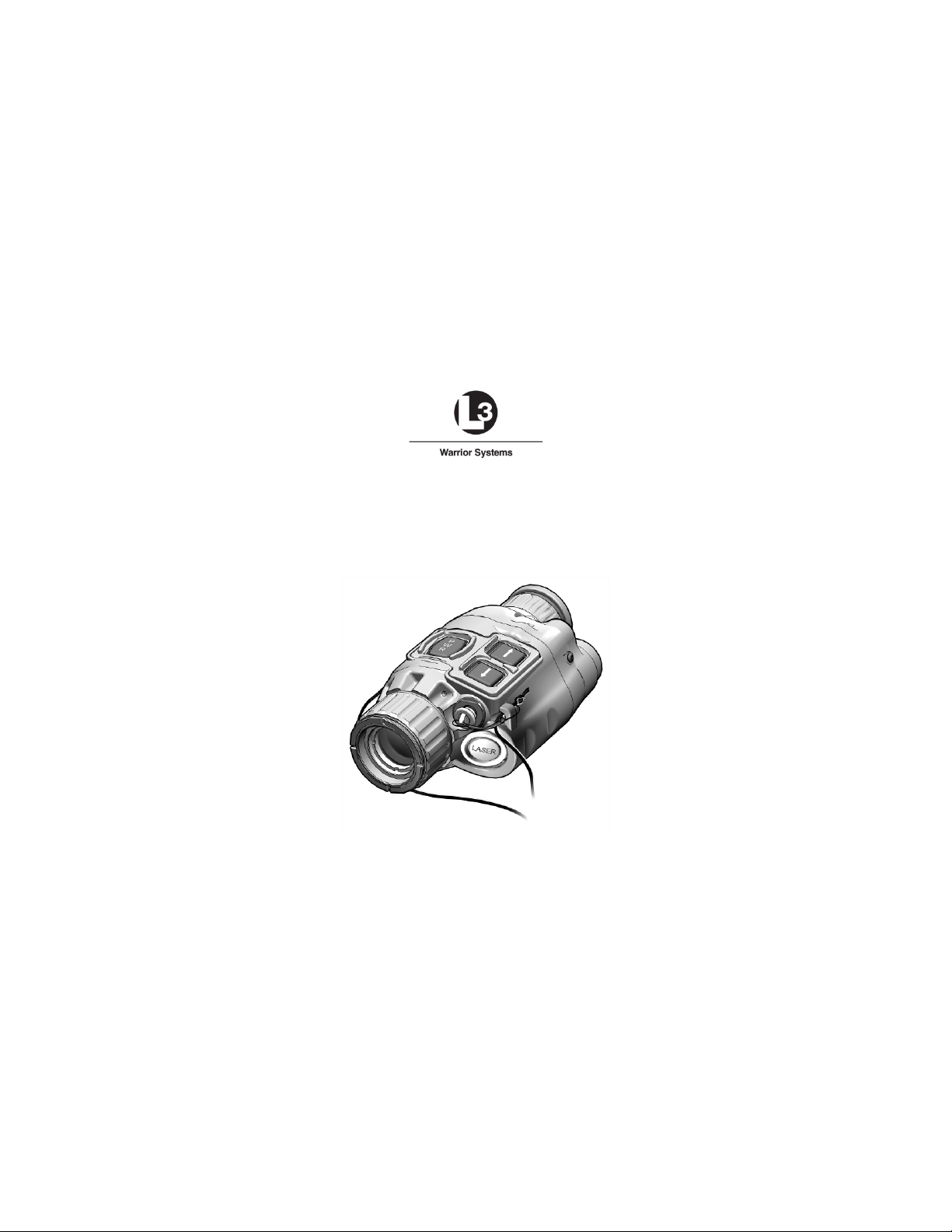
Figure 1-1 Weapon Mounted Mini Thermal Monocular
(WTM)
1.1 SCOPE
This manual is intended for use by operators of the Weapon
Mounted Mini Thermal Monocular (WTM). It provides a
system description, operational procedures, and
maintenance responsibilities. Complete familiarization with
this manual prior to using the equipment will ensure safe
operation and maximum effectiveness of the WTM.
1-1

Model
Laser Pointer
Rail
Visible
Laser Pointer
Picatinny
(MIL-STD-1913)
Laser Pointer
(MIL-STD-1913)
Laser Pointer
1.2 MODEL NUMBER AND EQUIPMENT NAME
This manual applies to the WTM models listed in Table 1-1.
WTM-000-A14
WTM-000-A16
WTM-000-A17
Table 1-1 WTM Models
Infrared (IR)
Infrared (IR)
Picatinny
Weaver™
Because this manual applies to several different WTM
models, pictures contained herein may not be representative
of the exact model purchased or issued.
1.3 MANUFACTURER
L-3 Communications Corporation
Warrior Systems Division
Insight Operations
9 Akira Way
Londonderry, NH 03053 USA
1.4 PURPOSE OF EQUIPMENT
The WTM is a battery operated, handheld or weapon
mounted thermal imaging device with an integrated Laser
Pointer (IR or Visible) and a digital camera.
1-2

BNC
Bayonet Neill-Concelman
C
Celsius
CAL
Calibration
cm
Centimeter
CW
Clockwise
F
Fahrenheit
IR
Infrared
ITAR
International Traffic in Arms Regulations
m
Meter
mrad
Milliradian
mW
Milliwatt
nm
Nanometer
PC
Personal Computer
PIC
Picture
RECAL
Recalibrate
RMA
Return Material Authorization
USB
Universal Serial Bus
V
Volt
VGA
Video Graphics Array
WHOT
White Hot (polarity)
WTM
Weapon Mounted Mini Thermal
Monocular
1.5 ABBREVIATIONS AND ACRONYMS
Abbreviations and acronyms used in this manual are listed
as follows:
BHOT Black Hot (polarity)
CCW Counterclockwise
LED Light Emitting Diode
NOHD Nominal Ocular Hazard Distance
REV Review
1-3

SECTION II
EQUIPMENT DESCRIPTION
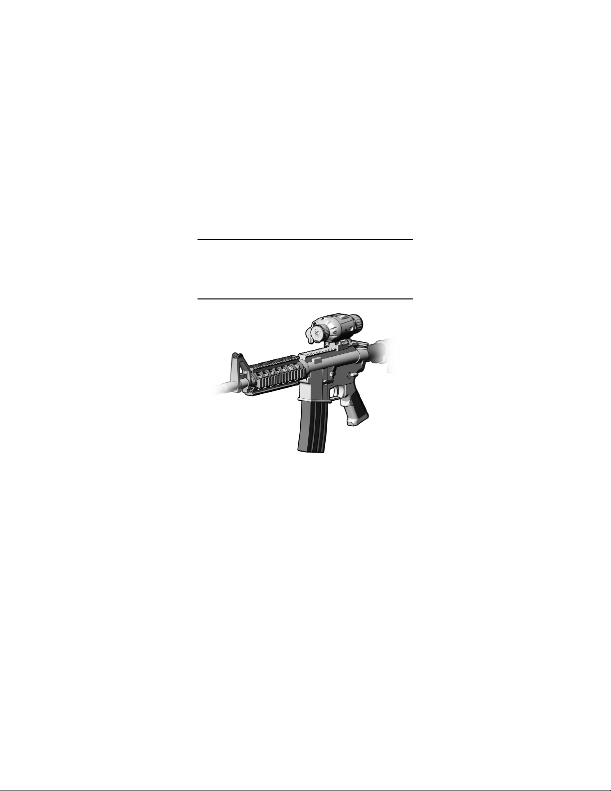
1.6 SYSTEM DESCRIPTION
The WTM is a battery operated, thermal imaging device with
an integrated Laser Pointer (IR or Visible) and digital
camera. It may be mounted to a standard tripod, an
AN/PVS-7 / PVS-14 helmet assembly, or to any weapon
equipped with a Picatinny (MIL-STD-1913) or Weaver rail.
The thermal imaging capability of the WTM allows for
observation and target identification under adverse
conditions including light rain, smoke, light snow, and low
light to total darkness. It will not allow the user to see
through glass, water, or heavy rain / snow.
Models equipped with a Visible Laser Pointer provide for
target acquisition in low light conditions without the need for
night vision devices. Models equipped with an IR Laser
Pointer provide for target acquisition in low light or complete
darkness when used in conjunction with night vision devices.
With the integrated camera, the WTM allows for acquisition,
storage, download, and recall of viewed thermal images.
Thermal images may also be transferred to a personal
computer.
The WTM is a ruggedized system designed for operation in
battlefield environments.
1-4

WEIGHT AND DIMENSIONS
Weight (with batteries)
< 16.0 ounces
Length
5.2 inches
Height
2.2 inches
POWER AND PERFORMANCE
Power Source
2 DL123A lithium batteries
Battery Operating Life1
4 hours continuous operation
Field of View
≥28° diagonal
Operating Temperature
-29°F (-34°C) to 120°F (49°C)
Immersion
66 feet for 2 hours
IR LASER POINTER
(If equipped)
Output Power
0.6 mW (± 0.1 mW)
Wavelength
840 nm (+10 / -20 nm)
VISIBLE LASER POINTER
(If equipped)
Output Power
4.3 mW (± 0.5 mW)
Beam Divergence
0.5 mrad (± 0.3 mrad)
Wavelength
645 nm (+10 / -5 nm)
1.7 TECHNICAL SPECIFICATIONS
Table 1-1 provides technical specifications for the WTM.
Table 1-2 Technical Specifications
Width 2.8 inches
Storage Temperature -40°F (-40°C) to 160°F (71°C)
Beam Divergence 0.5 mrad (± 0.3 mrad)
1
Performance will vary depending on actual environmental and atmospheric
conditions.
1-5
5
2 6 3
7
8
11
10
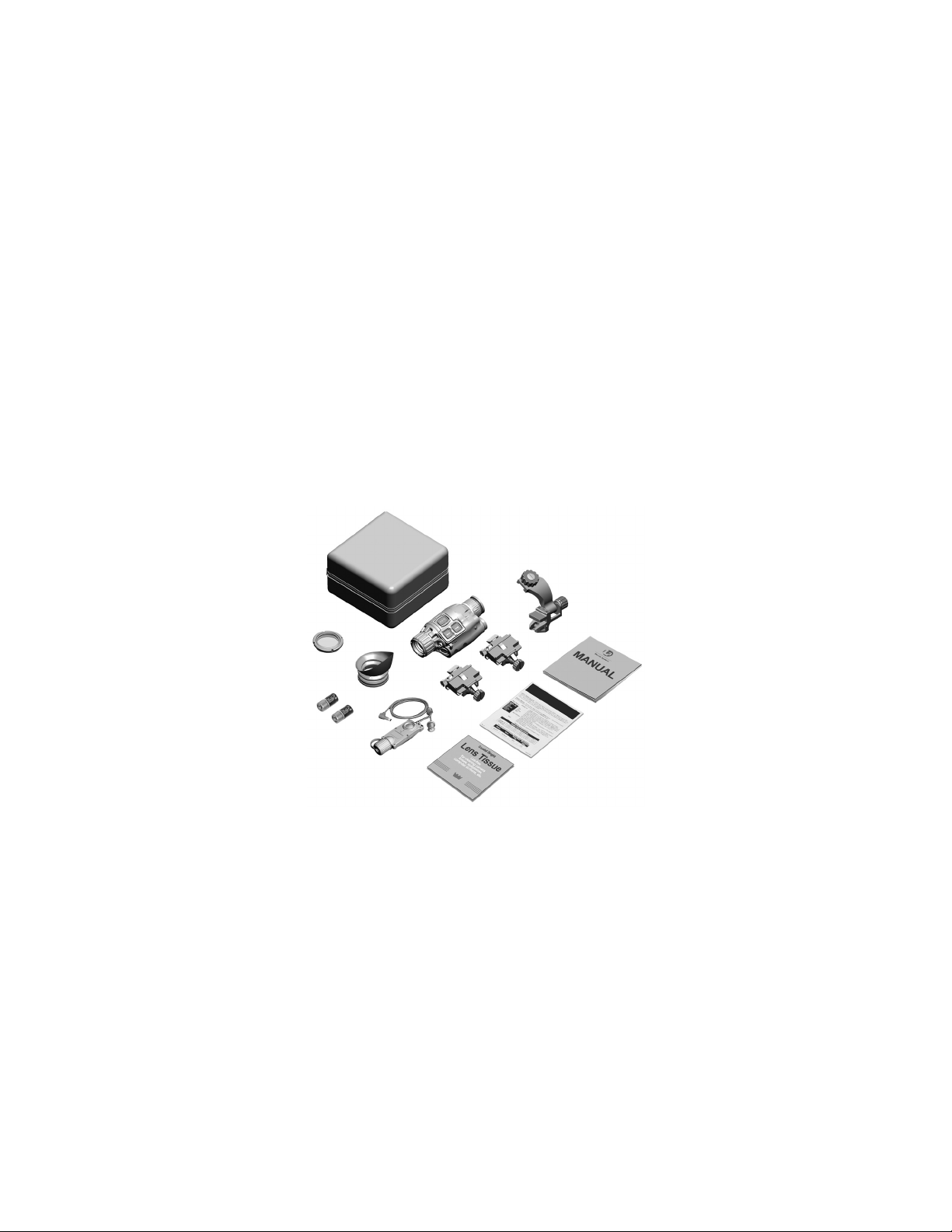
1.8 MAJOR COMPONENTS
The WTM is available in several models with a wide array of
accessory items. Figure 1-2 shows components and parts
for the entire family of WTM configurations. Therefore, some
of the items shown may not be applicable to your specific
configuration. Table 1-3 provides a brief functional
description of each item. The “Key” column in Table 1-3
corresponds to the label numbers in Figure 1-2.
1
12
1-6
9
Figure 1-2 Major Components
4

Major
Component
1
Soft Carrying
Protects the WTM and accessories
2
Helmet Adapter,
Allows the WTM to be installed on a
helmet mount.
3
Operator Manual
Provides detailed operating and
WTM.
4
Guide
procedures for the WTM.
WTM.
7
Picatinny
Mount Adapter
Allows the WTM to be mounted to any
(MIL-STD-1913) rail.
8
Weaver Mount
Adapter
Allows the WTM to be mounted to any
weapon equipped with a Weaver rail.
1.8 LIST OF MAJOR COMPONENTS – Continued
Table 1-3 List of Major Components
Key
Function
5
6
Case
AN/PVS-7/14
Quick Reference
Lens Tissue
Image Adapter
Cable
(MIL-STD-1913)
while in a field environment.
helmet equipped with an AN/PVS-7/14
maintenance instructions specific to the
Provides at-a-glance operating
Used to clean the optical lenses of the
Used to connect the WTM to an
external monitor for viewing live
imagery, or to a computer so that stored
thermal images may be viewed or
downloaded.
weapon equipped with a Picatinny
1-7

Major
Component
9
WTM Assembly
The WTM is a battery operated,
10
Eyecup
When attached, reduces emission of
stray light from the eyepiece.
11
Batteries,
DL123A (2)
Two 3V lithium batteries used to power
the WTM.
environments.
1.8 MAJOR COMPONENTS – Continued
Table 1-3 List of Major Components – Continued
Key
weapon-mounted or handheld thermal
imaging device with an integrated Laser
Pointer (IR or Visible) and digital
camera.
Function
12
1-8
Night Adaptive
Filter / Demist
Shield
When attached, prevents fogging of the
eyepiece and reduces backlighting and
loss of night vision in low light

CHAPTER 2
OPERATING INSTRUCTIONS
SECTION I
PREPARATION FOR USE
2.1 PREPARATION FOR USE
Unpacking the Equipment
Open the soft carrying case and verify that all major
components listed in Table 1-3 are present. Check the WTM
to ensure the following additional items are included:
a. Battery Cap Assembly
b. Video Jack Plug
c. Objective Lens Cover
d. Neck Cord
If any of the major components or items listed above are
missing, seek guidance from the equipment issuing
authority.
Inspection of the Equipment
Before use, inspect all pieces of equipment for any damage
such as cracks, loose parts, faulty cables, or other visible
defects. If any damage or defects are noted, seek guidance
from the equipment issuing authority.
2-1

2.2 BATTERY HANDLING
Battery Inspection
Before installation, inspect the batteries for any cracks,
dents, leakage, or bulging. Never install a defective battery
in the WTM.
WARNING
Ensure the WTM is OFF before attempting to
install, remove, or replace batteries.
Battery Installation
Access the battery compartment by turning the battery cap
counterclockwise. Install two fresh DL123A lithium batteries
with the positive terminals facing out as shown in Figure 2-1.
Replace the battery cap and turn clockwise to tighten.
Figure 2-1 Battery Installation
CAUTION
Do not ship or store the WTM with batteries
installed.
2-2

MOUNTING
MOUNTING
GROOVE
2.2 BATTERY HANDLING – Continued
Low Batte ry Indicator
A low battery message will appear in the eyepiece display
when approximately 15 minutes of continuous operation
remain. If the batteries are not replaced promptly when the
“LOW POWER” message appears, the display quality will
deteriorate rapidly.
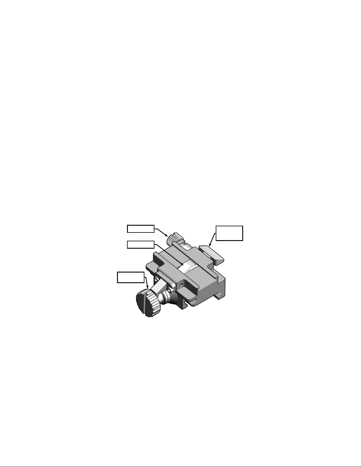
2.3 MOUNTING PROCEDURES
The WTM uses a versatile mounting bracket and adapters to
mount to a standard tripod, an AN/PVS-7 / PVS-14 helmet
assembly, or to any weapon equipped with a Picatinny
(MIL-STD-1913) or Weaver rail.
BRACKET
Figure 2-2 WTM Mounting Bracket
2-3

RELEASE
KNOB
2.3 MOUNTING PROCEDURES – Continued
WARNING
Be sure the WTM is OFF before attempting to
mount to a weapon, tripod, or helmet assembly.
Mounting to a Tripod
The WTM mounting bracket contains two screw holes with
female threading to accept a standard ¼”-20 tripod screw.
Align the threads and rotate the WTM clockwise until
securely mounted.
AN/PVS-7/14 Helmet Mount Adapter
The Helmet Mount Adapter allows the WTM to be installed
on an AN/PVS-7 / PVS-14 helmet assembly.
ADJUSTMENT
KNOB
Figure 2-3 AN/PVS-7/14 Helmet Mount Adapter
2-4

2.3 MOUNTING PROCEDURES – Continued
1. Hold the WTM with the eyepiece toward the operator and
the mounting bracket oriented as shown in Figure 2-4.
2. Slide the helmet mount adapter onto the WTM’s mounting
bracket.
3. Rotate the release knob clockwise or counterclockwise so
that the helmet mount adapter will seat properly in the
mounting groove of the mounting bracket.
4. The WTM may now be attached to a helmet mount.
Figure 2-4 Installing the AN/P VS-7/14 Helmet Mount
Adapter
Once mounted to an AN/PVS-7/14 helmet assembly, the
WTM can be moved in an arc to provide best alignment with
the operator’s eye.
2-5
KNOB
LEVER POST
QUICK
LEVER
2.3 MOUNTING PROCEDURES – Continued
1. Unscrew the adjustment knob to its full and open position.
2. Gently push the WTM away from the operator’s head and
rotate clockwise or counterclockwise until proper
positioning is achieved. Tighten the adjustment knob to
lock the WTM in place.
Mounting to a Weapon
Weapon mount adapters are available that allow the WTM to
be installed on any weapon equipped with a Picatinny
(MIL-STD-1913) or Weaver rail. Regardless of the type of
adapter that you are issued, the procedure for attachment to
the WTM is the same.
LEVER LOCK
CLAMPING
RELEASE
2-6
Figure 2-5 Weapon Mount Adapter
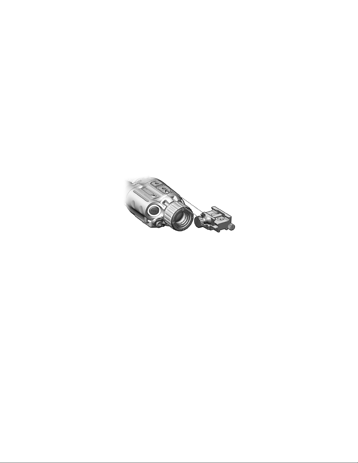
2.3 MOUNTING PROCEDURES – Continued
WARNING
Be sure the weapon is clear and safe before
proceeding.
Figure 2-6 Installing the Weapon Mount Adapter
1. Hold the WTM with the eyepiece toward the operator, and
the mounting bracket oriented as shown in Figure 2-6.
2. While pressing the quick release lever, slide the weapon
mount adapter onto the mounting bracket.
3. Let go of the quick release lever. Slide the weapon
mount adapter until the lever post engages the mounting
groove on the mounting bracket.
4. Turn the lever lock clockwise as tightly as fingers allow.
5. The WTM may now be attached to a weapon.
2-7

2.3 MOUNTING PROCEDURES – Continued
Mount the WTM to the weapon rail as follows:
RECOIL LUG
Figure 2-7 Weapon Mount Adapter Installed
1. Loosen the clamping knob on the weapon mount adapter
until the jaws have sufficient space to fit over the
weapon’s rail.
2. Position the weapon mount adapter on the rail, ensuring
that the recoil lug is seated in the desired recoil groove of
the rail.
3. Turn the clamping knob clockwise as tightly as fingers
allow, then use a coin or similar flat object in the slot of
the clamping knob to turn it an additional 180 degrees.
4. Zero the WTM to the host weapon on a 25-meter range
per section 2.4.
2-8

2.3 MOUNTING PROCEDURES – Continued
NOTE
The WTM may be placed at any position (forward
and aft) on the rail that is most convenient for the
operator. If, however, the WTM is removed from
the rail, the operator must make note of the
position at which it was zeroed, and return it to
that same position to ensure that zero is
maintained.
NOTE
If, for whatever reason, the lever lock becomes
loose, retighten and perform the 25-meter zeroing
procedure described in section 2.4.
2.4 ZEROING PROCEDURES
This procedure is used to zero the WTM to the host weapon
on a 25-meter range.
NOTE
Each click of the WTM reticle moves the shot
group 3.1cm at 25 meters (when in ZOOM 1X).
Other click equivalents are provided in Table 2-1.
Changing the position of the reticle corresponds to
a subsequent change in shot group movement
(i.e., the UP button will move the strike group up).
2-9

Shot Group Movement
10 m
25 m
100 m
150 m
300 m
ZOOM 1X
1.2cm
3.1cm
12cm
18.5cm
36.9cm
ZOOM 2X
0.6cm
1.5cm
6cm
9.25cm
8.45cm
2.4 ZEROING PROCEDURES – Continued
Table 2-1 Reticle Adjustments
1. On a 25-meter zeroing target, mark the designated strike
point and designated strike zone using the target offset
values in Table 2-2.
2. Mount the target on an “E” silhouette or other suitable
surface at 25 meters.
3. Mount the WTM to the weapon.
4. Power up the WTM as described in section 2.7.
5. Align the WTM reticle with the center of the target per
section 2.16, RETICLE.
6. Fire a 3-round shot group and note the center of the shot
group relative to the designated strike point.
7. Adjust the position of the reticle to move the center of the
shot group to the designated strike point.
8. Fire another 3-round shot group and again observe the
center of the new shot group relative to the designated
strike point.
9. When 2 out of 3 rounds are in the designated strike zone,
the WTM / weapon combination is zeroed.
2-10

0.0
2.9D
2.4 ZEROING PROCEDURES – Continued
Table 2-2 Mounting Configurations and Weapon Offsets
Weapon Mount
M4/M4A1 Top Mount 300m
Range Zeroed
To
25m Target Zero
Offset Squares
2.5 OBJECTIVE LENS AND EYEPIECE
Objective Lens
Whenever the WTM is not being used, the objective lens
cover should be fitted over the objective lens to protect it
from possible damage. The objective lens cover should also
be installed when calibrating the WTM (see section 2.9).
Night Adaptive Filter / Demist Shield
When installed, the night adaptive filter / demist shield
prevents the eyepiece from fogging, and reduces
backlighting and loss of night vision in low light
environments. The filter / shield is installed as follows:
1. Place the filter / shield over the eyepiece with the
threaded side down.
2. Carefully turn the filter / shield clockwise to screw it into
the eyepiece assembly.
3. Insert the end of a pen, paper clip, or similar item into one
of the four retaining ring grooves. Rotate the retaining
ring clockwise to tighten.
2-11

2.5 OBJECTIVE LENS AND EYEPIECE – Continued
Eyecup
When attached, the eyecup reduces emission of stray light
from the eyepiece. To install, gently snap into place over the
eyepiece assembly. Rotate the eyecup to obtain a proper
eye socket and cheek weld.
2-12

POWER
BUTTON
DIOPTER
BUTTONS
VIDEO JACK
PLUG
LASER
BUTTON
SECTION II
OPERATING INSTRUCTIONS
2.6 FEATURES AND CONTROLS
Figures 2-8 and 2-9 show the features and controls for the
WTM. This section provides details regarding their function
and operation.
LASER LED
UP / DOWN
ADJUSTER
EYEPIECE
Figure 2-8 Features and Controls
VIDEO JACK
2-13

LASER
POINTER
LENS COVER
BATTERY CAP /
COMPARTMENT
FOCUS RING
2.6 FEATURES AND CONTROLS – Continued
OBJECTIVE
Figure 2-9 Features and Controls – Continued
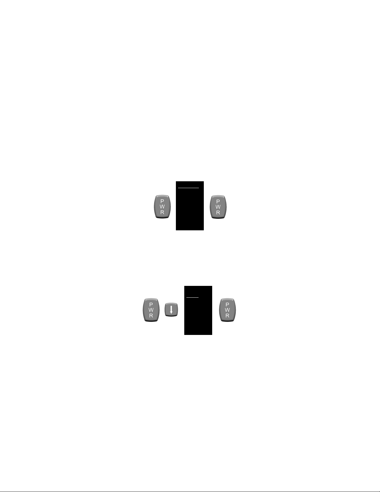
2.7 POWER
To turn on the WTM, press the PWR button and wait 2 to 5
seconds for the system prompt, and then press the PWR
button again. The WTM will power up with the same settings
selected as when the system was last turned off.
To turn off the WTM, press and hold the PWR button for
approximately 3 seconds as the messages OFF? then OFF!
appear sequentially in the eyepiece display. Release the
PWR button when the eyepiece display turns dark.
2-14

System
Status
press again
Press (and hold) for about 3
turns off
Calls up Main
item
System
Status
How Button is
Pressed
ON
Single tap
Scrolls through the menu
Displayed
ON
Displayed
Press and hold
simultaneously
2.8 BUTTON FUNCTIONS
WTM buttons are multi-functional and produce different
results depending on the system status (i.e., ON, OFF) and
how the buttons are pressed. See Tables 2-3 and 2-4.
Menu Displayed
Table 2-3 PWR Button Operation
How Button is Pressed Result
Press, wait 2 to 5 seconds
OFF
ON
ON Single tap
ON
for system prompt, then
seconds until display screen
Single tap
Turns on WTM
(see section 2.7)
Turns off WTM
(see section 2.7)
Menu
Activates the
highlighted menu
Table 2-4 UP / DOWN Button Operation
Result
Menu Displayed
ON
Menu NOT
Menu NOT
(either button)
Single tap
(either button)
both buttons
items
Calls up gain control
(see section 2.11)
Initiates a calibration
(see section 2.9)
2-15

2.9 CALIBRATION
After prolonged use, or after transitions from one
temperature extreme to another, a degradation of the
thermal image may be noticed. In these instances, and
during initial startup, the WTM should be calibrated to
optimize the viewed thermal image.
Calibration is accomplished by simultaneously pressing (and
holding) the UP / DOWN buttons, or via the system menu
(see section 2.16, Calibration (CAL)). Regardless of which
method is used, the objective lens cover must first be placed
over the objective lens. Failure to do so may result in a
distorted picture or the presence of ghost images in the
eyepiece display.
The WTM is equipped with an internal sensor that detects
significant changes in temperature. When this condition
occurs, the message “RECAL” will appear in the eyepiece
display indicating that the operator should calibrate the WTM
as described above.
2.10 DIOPTER ADJUSTMENT
The eyepiece may be focused to accommodate differences
in individual operators’ eyesight. Diopter adjustments may
be made as follows:
1. With the system powered on, press the PWR button to
call up the Main Menu.
2. While looking through the eyepiece display, rotate the
diopter adjuster until the menu text appears sharp and
clear.
2-16

MIN
Status Bar
2.11 GAIN ADJUSTMENT
When the Main Menu is NOT displayed, pressing either the
UP or DOWN button calls up the gain control settings. Gain
controls are presented in the eyepiece display as shown in
Figure 2-10.
GAIN
MAX
|
― ―
|
Figure 2-10 Gain Control
Gain is adjusted by pressing the UP / DOWN buttons to
move the status bar along the MAX / MIN line. If the UP /
DOWN buttons are not pressed within three seconds, the
gain control scale will disappear and the WTM will revert to
normal viewing mode. Once adjusted, the gain will remain at
the applied setting (even if the WTM is turned off) until
readjusted by the operator.
Repeatedly pressing the UP / DOWN buttons will move the
status bar in single increments. Pressing and holding the
UP / DOWN buttons will auto-scroll the status bar in multiple
increments.
2-17

2.12 OBJECTIVE FOCUS
The objective lens must be focused for the viewing distance
being observed. Rotate the objective focus ring for best
image clarity. A change in viewing distance requires that the
objective lens be refocused. If already focused for a
distance of at least 15 meters (49 feet), no change in focus
is required between this distance and infinity. When the
WTM is not being used, install the objective lens cover over
the objective lens to protect it from possible damage.
2.13 STARTUP PROCEDURES
To achieve optimal performance and image clarity, the
following procedures should be accomplished in the order
presented, each time the WTM is to be used:
1. Turn on the WTM by pressing the PWR button. Wait 2 to
5 seconds for the system prompt and press the PWR
button again.
2. Install the objective lens cover and perform a calibration
as described in section 2.9.
3. Access the Main Menu by pressing the PWR button.
While looking through the eyepiece display, rotate the
diopter adjuster until the menu text appears sharp and
clear.
4. Remove the objective lens cover and adjust the gain
setting as described in section 2.11 to achieve a
comfortable contrast level.
5. While looking through the eyepiece at an object at least
one meter away, rotate the objective focus ring to obtain
the best (sharpest) thermal image.
2-18

2.14 LASER POINTER
With the WTM powered on, pressing (and holding) the
LASER button activates the laser pointer until pressure is
released from the button. Continuous activation is
accomplished by double-tapping the LASER button. While
in continuous mode, pressing the LASER button again
(single-tapping) turns off the laser.
When the laser pointer is activated, a dot appears in the
center of the display reticle. Additionally, black and white
squares appear in the top right and bottom left corners of the
display as shown in Figure 2-11. Further indication that the
laser pointer is activated is provided by the green laser LED
shown in Figure 2-8.
Figure 2-11 Display with Laser Pointer Activated
|
― ▪ ―
|
2-19

ZOOM 1X
WHOT
CAL
PIC
REV
RS170
RETICLE
HAND
EXIT
SECTION III
SYSTEM MENU
2.15 MENU NAV IG ATION
With the WTM turned on, access the Main Menu by pressing
the PWR button. Menu items are then selected (underlined)
by scrolling with the UP / DOWN buttons. Pressing the PWR
button again activates the selected menu item. If the UP /
DOWN or PWR buttons are not pressed within
approximately 10 seconds, the Main Menu will disappear
and the WTM will revert to normal viewing mode. Once
activated, menu options will remain at the applied setting
(even if the WTM is turned off) until reset by the operator.
2.16 MAIN MENU
The Main Menu is shown in Figure 2-12. The following
paragraphs describe available menu options.
Figure 2-12 Main Menu
2-20
ZOOM 1X
WHOT
CAL
PIC
REV
RS170
RETICLE
HAND
EXIT
Toggle with:
ZOOM 1X
WHOT
CAL
PIC
REV
RS170
RETICLE
HAND
EXIT
2.16 MAIN MENU – Continued
ZOOM 1X / ZOOM 2X
Activating the ZOOM 1X / ZOOM 2X menu item toggles
between a 1x and 2x magnified viewed image.
Toggle with:
Figure 2-13 Menu – ZOOM 1X / ZOOM 2X
White Hot (WHOT) / Black Hot (BHOT)
Activating the WHOT / BHOT menu item toggles between
white hot and black hot polarity modes. When in WHOT
mode, objects with the hottest thermal signature will appear
white and those with the coolest thermal signature will
appear black. In BHOT mode, the reverse is true.
Figure 2-14 Menu – White Hot / Black Hot
2-21

ZOOM 1X
WHOT
CAL
PIC
REV
RS170
RETICLE
HAND
EXIT
2.16 MAIN MENU – Continued
Calibration (CAL)
The system menu provides one method of calibrating the
WTM. See section 2.9 for a more detailed description of the
calibration procedures.
NOTE
Failure to cover the objective lens prior to
calibrating the WTM may result in a distorted
picture or the presence of ghost images in the
eyepiece display.
Calibrating the WTM via the system menu is accomplished
as follows:
1. Install the objective lens cover over the objective lens.
2. Activate the CAL menu item as shown below.
3. The message “CALIBRATING” will appear as the unit
performs the calibration. Once complete (< 3 seconds),
the message will disappear and the WTM will revert to
normal viewing mode.
4. Remove the objective lens cover.
Figure 2-15 Menu – Calibration (CAL)
2-22

ZOOM 1X
WHOT
CAL
PIC
REV
RS170
RETICLE
HAND
EXIT
2.16 MAIN MENU – Continued
Picture (PIC)
Activating the PIC menu item takes a digital picture of the
viewed image. The image is automatically stored to flash
memory with a maximum capacity of approximately 150
pictures. When attempting to take more than the maximum
allowable number of pictures, the words “CAMERA FULL”
will appear in the eyepiece display.
No more pictures may be taken until one or more of the
stored pictures are deleted (see section 2.16, Review
(REV)).
Figure 2-16 Menu – Picture (PIC)
2-23

KEEP
DELETE
DELETE ALL!
EXIT
ZOOM 1X
WHOT
CAL
PIC
REV
RS170
RETICLE
HAND
EXIT
2.16 MAIN MENU – Continued
Review (REV)
Activating the REV menu item allows for review of stored
pictures.
Scroll with:
Figure 2-17 Menu – Review (REV)
Pressing the UP / DOWN buttons brings up the next /
previous stored picture. While in review mode, pressing the
PWR button again calls up the Review sub-menu shown
below.
Figure 2-18 Menu – Review Sub-Menu
2-24

2.16 MAIN MENU – Continued
1. Activating the KEEP sub-menu item returns the display to
the review picture mode.
2. Activating the DELETE sub-menu item permanently
removes the selected picture from flash memory and
returns the display to the review picture mode.
3. Activating the DELETE ALL! sub-menu item permanently
removes all stored pictures from flash memory and
returns the display to normal viewing mode.
4. Activating the EXIT sub-menu item returns the display to
normal viewing mode.
NOTE
The WTM does not “remember” the polarity or
zoom settings in place at the time a picture was
taken. When reviewing stored images through the
eyepiece display, they will appear with polarity and
zoom characteristics currently selected.
2-25

ZOOM 1X
WHOT
CAL
PIC
REV
RS170
RETICLE
HAND
EXIT
2.16 MAIN MENU – Continued
RS170 / VGA
Activating the RS170 / VGA menu item toggles between
these two display formats. VGA format is appropriate for
high-motion viewing. RS170 format is appropriate for all
other applications. See section 2.17, Viewing Live Imagery
for instructions on how to connect the WTM to an external
monitor for viewing live thermal imagery.
Toggle with:
Figure 2-19 Menu – RS170 / VGA
NOTE
When viewing the WTM thermal image on an
external monitor, the RS170 video format must be
selected. Using the VGA video format for this
purpose will result in an extremely distorted image.
2-26

ZOOM 1X
WHOT
CAL
PIC
REV
RS170
RETICLE
HAND
EXIT
EXIT
AZ 0
EL 0
OFF
2.16 MAIN MENU – Continued
RETICLE
Figure 2-20 Menu – RETICLE
Activating the RETICLE menu item calls up the sub-menu
shown in Figure 2-21. The sub-menu controls the position of
the reticle in the eyepiece, and turns the reticle ON/OFF.
Figure 2-21 Menu – RETICLE Sub-Menu
1. Activating the EXIT sub-menu item returns the display to
the Main Menu while leaving the reticle turned on.
2. Activating the AZ sub-menu item moves the reticle along
the horizontal axis. Press PWR to select and use the
UP / DOWN buttons to move the center of the reticle left
or right.
2-27

2.16 MAIN MENU – Continued
3. Activating the EL sub-menu item moves the reticle along
the vertical axis. Press PWR to select and use the UP /
DOWN buttons to move the center of the reticle up or
down.
4. Activating the OFF sub-menu item toggles the reticle off
and returns the display to the Main Menu.
NOTE
When adjusting reticle position, AZ (azimuth) and
EL (elevation) values are displayed in the lower
left corner of the display. The numbers represent
“clicks” of the reticle. Azimuth and elevation
values can rapidly be returned to 0 by pressing the
UP / DOWN buttons simultaneously. When in
ZOOM 1X mode, the reticle is moved in 2-click
increments each time the UP / DOWN buttons are
pressed. The reticle is moved in 1-click
increments when in ZOOM 2X mode. Once
adjusted, the reticle position will remain at that
setting (even if the WTM is turned off) until
readjusted by the operator.
HAND / HELMET
Activating the HAND / HELMET menu item toggles between
these two display options to accommodate the WTM being
used as either a handheld or helmet-mounted device.
Toggling between the two options will rotate all text (not the
image) 180 degrees for readability purposes and ease of
use. The position of the reticle is unaffected and will remain
aligned to the laser.
2-28

ZOOM 1X
WHOT
CAL
PIC
REV
RS170
RETICLE
HAND
EXIT
ZOOM 1X
WHOT
CAL
PIC
REV
RS170
RETICLE
HAND
EXIT
2.16 MAIN MENU – Continued
Figure 2-22 Menu – HAND / HELMET
EXIT
Exit the Main Menu by activating the EXIT menu item. This
action saves all changes made and returns the WTM to
normal viewing mode.
Figure 2-23 Menu - EXIT
2-29

USB
CONNECTOR
DOWNLOAD
BUTTON
CABLE PLUG
BNC
CONNECTOR
SECTION IV
EXTERNAL VIEWING / IMAGE DOWNLOAD
2.17 IMAGE ADAPTER C ABLE
The WTM comes with an Image Adapter Cable that is used
to:
• connect the WTM to an external monitor for viewing
live thermal imagery, or
• connect to a personal computer (PC) so that
captured thermal images may be viewed and/or
downloaded.
The Image Adapter Cable is shown in Figure 2-24.
LED
Figure 2-24 Image Adapter Cable
2-30

2.17 IMAGE AD APTER CABLE – Continued
Viewing Live Imagery
Viewing live thermal imagery from the WTM on an external
monitor is accomplished by:
1. Remove the video jack plug (captive to the WTM) from
the video jack.
2. Plug the Image Adapter into the WTM by aligning the
white dot on the cable plug with the white dot on the jack.
Push the cable plug into the jack until it locks into place.
3. Attach the BNC connector to an external monitor or
television.
4. Follow the WTM startup procedures contained in section
2.13 and ensure RS170 video format is selected from the
Main Menu as described in section 2.16, RS170 / VGA.
5. Follow instructions provided by the manufacturer of the
monitor or television for viewing video from an external
device.
CAUTION
When the cable plug is inserted into the video
jack, it automatically locks in place. To remove it,
pull straight back on the cable plug. Do not
remove the cable plug by pulling on the cable.
2-31

2.17 IMAGE AD APTER CABLE – Continued
Retrieving Stored Images
Images stored in the WTM may be downloaded to the Image
Adapter Cable and converted to either a .tiff or .jpeg file
format (depending on model). Once downloaded, images
may then be viewed, saved, edited, and/or deleted by a PC
in the same manner as any files accessed through an
external drive. The Image Adapter Cable can store in
excess of 400 .tiff files. Storage capacity for .jpeg files is
considerably higher.
NOTE
The download process does not remove any of the
raw images from the WTM’s flash memory.
Deleting saved pictures from the WTM must be
accomplished as described in section 2.16,
Review (REV).
1. Plug the Image Adapter Cable into the WTM by aligning
the white dot on the cable plug with the white dot on the
video jack. Push the cable plug into the jack until it locks
into place.
2. Insert the Image Adapter’s Universal Serial Bus (USB)
connector into a free USB port on the computer. The PC
will recognize the Image Adapter as an external hard
drive and will normally open a Windows Explorer dialogue
box to display the contents of the drive.
3. Wait for the LED on the Image Adapter to turn solid
green. Other LED status indicators are described in
Table 2-5.
2-32

LED Indicator
Status Condition
Green (steady)
Powered and passed self test
Green flashing
Data transfer in progress
Red (steady)
Powered but failed self test
Red flashing
Operational error
2.17 IMAGE AD APTER CABLE – Continued
4. Press the Download Button. This action downloads all
images stored in the WTM’s flash memory, converts them
to .tiff (or .jpeg) format, and saves them to the flash
memory of the Image Adapter Cable. The LED on the
Image Adapter will flash green during this process.
NOTE
The Image Adapter creates a separate folder for
each of the WTM devices it has been connected
to. Initiating the download process from the same
WTM will cause the Adapter to overwrite the
existing folder. Renaming the folder prior to
downloading new images will preserve the content
of the original folder.
5. Wait for the LED on the Image Adapter to return to a
steady green state indicating that the transfer process is
complete. Open or refresh the Windows Explorer
dialogue box to view the contents of the Image Adapter’s
flash memory. Images may then be viewed, saved,
edited, and/or deleted in the same manner as any files
accessed through an external drive.
Table 2-5 LED Status Indicators
2-33

2-34

Malfunction
Probable Cause
Corrective A ction
1. No display is
a. WTM was not successfully
a. Ensure that the PWR
b. Batteries are improperly
installed.
b. Verify that the batteries
are properly installed.
c. Battery power is low.
c. Replace existing batteries
d. Objective lens cover is
installed.
d. Remove objective lens
cover.
e. Battery compartment
e. Clean the battery
CHAPTER 3
MAINTENANCE
OPERATOR MAINTENANCE
3.1 TROUBLESHOOTING
The procedures below will help correct some of the basic
problems that may arise with the WTM. If the equipment
malfunction is not listed, or the actions listed do not correct
the fault, refer to section 3.4 for additional guidance.
Table 3-1 Troubleshooting Procedures
SECTION I
present when
turning on the WTM.
activated.
corroded.
button has been pressed
twice as described in Table
2-3.
with fresh batteries.
compartment per section
3.2, Battery Compartment.
3-1

Malfunction
Probable Cause
Corrective A ction
2. Display is ON but
a. Objective lens cover is
installed.
a. Remove objective lens
cover.
b. WTM requires
b. Install the objective lens
section 2.9.
c. WTM needs to be
c. Adjust diopter and
d. WTM gain setting out of
alignment.
d. Adjust the gain setting
per section 2.11.
e. Viewed scene has no
e. Verify that the scene
3. Laser Pointer
a. Laser port requires
a. Clean the WTM laser port
Surfaces.
b. Battery power is low.
b. Replace existing batteries
with fresh batteries.
c. Battery com partment
c. Clean the battery
3.1 TROUBLESHOOTING – Continued
Table 3-1 Troubleshooting Procedures – Continued
no thermal images
are displayed.
appears weak or is
not visible down
range.
recalibration.
refocused.
thermal contrast.
cleaning.
corroded.
cover and perform a
calibration of the WTM per
objective focus.
being viewed has thermal
contrast.
per section 3.2, Optical
compartment per section
3.2, Battery Compartment
3-2

3.2 INSPECTION / CLEANING
The operator should inspect the WTM before each use and
after it has been in extreme conditions, such as prolonged
exposure to intense temperatures. The following procedures
will extend the life of the WTM and help ensure safe
operation.
WARNING
Prior to performing any inspection or maintenance
procedure, verify that batteries are not installed.
Batteries
Inspect the batteries for cracks, dents, leakage, or bulging.
If a battery shows signs of damage, remove and dispose of
properly. Replace batteries as required per section 2.2,
Battery Installation.
WTM Housing
Inspect the WTM housing for any signs of damage including
cracks, missing parts, and any other visible defects. Rinse
the WTM housing with water or mild soap and water and
then wipe dry with a soft cloth. Clean around buttons and
brackets with a cotton swab.
Battery Compartment
Inspect the battery compartment for dirt, dust and corrosion.
Dirt or debris that cannot be shaken loose from the battery
compartment may be removed using a clean cloth or cotton
swab.
3-3

Battery Cap
Inspect the battery cap for dirt, sand and grime. Thoroughly
clean the battery cap and o-ring by flushing with water and
wiping with a cotton swab. Periodically lubricate the o-ring
with fluorinated grease. Replace the battery cap assembly if
the o-ring becomes cut, nicked, or dried out.
Optical Surfaces
Inspect the laser port and optical surfaces of the WTM for
foreign material. Remove any large particles or loose dirt
using air or a soft cloth. Fine cleaning should be performed
using lens tissue. Clean water, alcohol, or general purpose
window cleaner may be used to remove stubborn stains.
Avoid using excessive force as this may scratch the lenses.
Video Jack
Inspect the video jack for corrosion, dirt and damage. Gently
remove any large particles of foreign matter and clean the
contacts with alcohol and a cotton swab.
Image Adapter Cable
Inspect the Image Adapter Cable for frayed wires, loose
connectors, and any other possible damage to the cable. As
required, clean the connectors with alcohol and a cotton
swab.
3-4
3.3 CORRECTIVE MAINTENANCE PROCEDURES
The WTM
has no internal parts or assemblies replaceable
by the user or organizational level personnel. Refer to
section 3.4 regarding maintenance and/or repair actions
beyond those described in this manual.
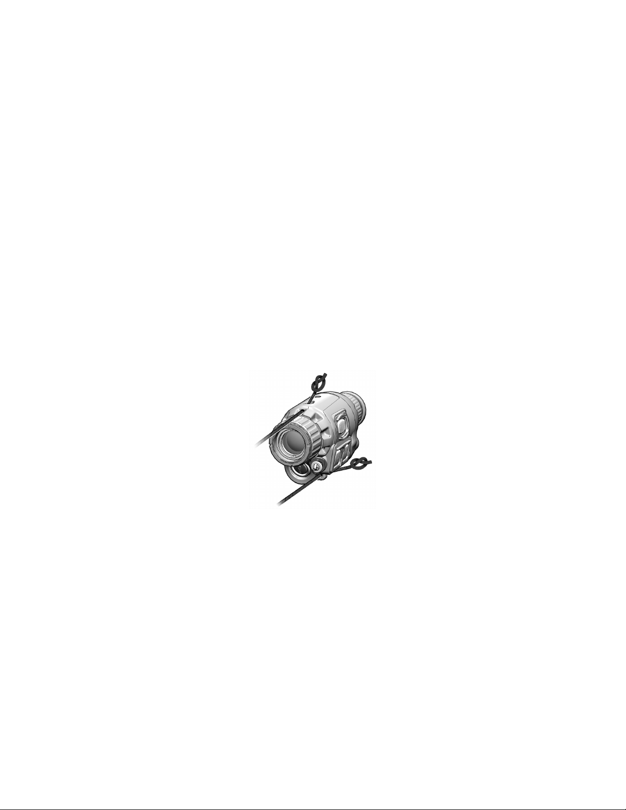
Replacing Neck Cord
No tools are required to perform this procedure.
1. Feed the ends of the replacement neck cord through the
channels of the WTM housing as shown in Figure 3-1.
Figure 3-1 Replacing Neck Cord
2. Tie a half knot in each end of the neck cord.
3. Pull back on the neck cord so that the half knots are snug
against the WTM housing.
3-5

3.3 CORRECTIVE MAINTENANCE PROCEDURES Continued
Replacing Battery Cap Lanyard
No tools are required to perform this procedure.
1. Unscrew the battery cap until it comes free of the battery
compartment threads.
2. Pull the battery cap lanyard over the battery compartment
threads.
3. Separate the lanyard from the battery cap.
4. Stretch smaller eye of the replacement lanyard over the
post on the battery cap.
5. Pull large end of replacement lanyard over battery cap
threads (see Figure 3-2). Work the lanyard down until it
is seated neatly in the groove closest to the WTM
housing.
Figure 3-2 Replacing Battery Cap Lanyard
6. Replace and tighten battery cap.
3-6
POST

SECTION II
SERVICE / PACKING AND UNPACKING
3.4 RETURN INSTRUCTIONS
For service, repair, or replacement, first e-mail
returns.insight@l-3com.com
or call toll-free 1-877-744-4803.
To assist with determining if the item is repairable, the
following information will be requested:
a. Serial number of the defective item;
b. Thorough description of the malfunction, defect, or
damage; and
c. If known, an explanation as to how the malfunction,
defect or damage occurred.
If the item is determined to be Beyond Economical Repair,
follow applicable replacement procedures through your
Property Officer. If it is determined that the item is under
warranty, or should be returned for repair, a Return Material
Authorization (RMA) number will be provided.
When returning the WTM for service / repair, the following
procedures should be followed to prevent any additional
damage:
a. Be sure that the WTM is free of all contaminants
such as dirt or any other foreign material.
b. Remove batteries.
c. Place the WTM in the soft carrying case.
3-7

3.4 RETURN INSTRUCTIONS – Continued
Place the item and a copy of the test report or detailed
description of the failure in a suitable packing container.
Mark the package with “Field Return” and the RMA number.
Ship via fastest, traceable, pre-paid means to:
L-3 Communications Corporation
Warrior Systems Division
Insight Operations
9 Akira Way
Londonderry, NH 03053
3.5 WARR ANTY INFORMATION
The WTM is under warranty from defects in material and
workmanship for a minimum of one (1) year from the date of
manufacture. This warranty does not protect against
damage due to misuse, mishandling or battery leakage.
Additional warranty coverage may have been provided
through the contract or via subsequent contract extension.
Specific warranty terms can be obtained from your
procurement agent, Contracting Officer or L-3 Warrior
Systems, Insight.
3.6 NON-WARRANTY INFORMATION
Non-warranty repairs are subject to an evaluation fee. The
item will be tested and evaluated for failure, then customer
permission and payment terms are obtained prior to any
repairs being performed.
3-8

4
5
6
8
11
10
APPENDIX A
END ITEM COMPONENTS AND REPAIR PARTS
SCOPE
This Appendix lists end item components and repair parts for
the entire family of WTM configurations.
1
2
12
9
3
7
Figure A-1 End Item Components
A-1

ITEM
NATIONAL
PART
1
8105-01-585-6183
ATP-012
Soft Carrying Case
1
2
5855-01-559-9639
NVM-042
Helmet Adapter
1
3
N/A
WTM-TM-VISIR
Operator Manual
1
4
N/A
WTM-QRG-VISIR
Quick Reference Guide
1
5
6760-01-556-4306
7B626
Lens Tissue
1
6
5855-01-579-5690
WTM-030-A1
Image Adapter Cable
1
Picatinny (MIL-STD-1913)
Weapon Mount Adapter
8
5340-01-582-7719
WTM-010-A2
Weaver Weapon Mount Adapter
1
WTM Assembly (see Figure A-2
10
TBD
MTM-079
Eyecup
1
11
6135-01-351-1131
DL123ABK
Battery, 3V Lithium
2
Night Vision Filter /
SCOPE – Continued
Table A-1 List of End Item Components
NO.
STOCK NUMBER
NUMBER
DESCRIPTION QTY
7 TBD WTM-010-A1
9 N/A N/A
12 6760-01-556-3413 MTM-018
A-2
for parts breakdown)
Demist Shield
1
1
1

ITEM
NATIONAL
PART
1
5340-01-556-3418
EH-C0117
Video Jack Plug
1
2
5855-01-585-6619
WTM-512
Objective Lens Cover
1
3
TBD
WTM-365
Battery Cap
1
4
1240-01-536-9661
MFL-173
Retainer, Battery Cap
1
5
5331-01-537-0498
AS-568A-018S70
O-Ring, Battery Cap
1
6
TBD
WTM-061-A1
Lanyard, Objective Lens Cover
1
7
4020-01-585-6611
MTM-073
Neck Cord
1
2
3 6 5
4
SCOPE – Continued
1
NO.
7
STOCK NUMBER
Figure A-2 WTM Assembly
Table A-2 List of Repair Parts
NUMBER
DESCRIPTION QTY
A-3

A-4

The WTM
Is designed and produced by:
L-3 Communications Corporation
Warrior Systems Division
Insight Operations
Londonderry, NH 03053
Phone 603.626.4800 / Fax 603.626.4888
www.l3warriorsystems.com
This manual contains technical data whose export is gover ned
by the U.S. International Traffic in Arms Regulations (ITAR).
This information must not be transferred to a foreign person
without the proper authorization of the U.S. Government. Please
contact L-3 Warrior Systems for more information.
© 2011 L-3 Communications Corporation
Warrior Systems Division
9 Akira Way
USA

 Loading...