

Page 1

MPMLED-TM-ITI
OPERATOR MANUAL
FOR THE
Mini Integrated Pointer Illuminator Module
(MIPIM)
Rev. 1 06 February 2012
Page 2

Page 3

SAFETY SUMMARY
GENERAL
This manual contains operating instructions and
maintenance procedures which may cause injury or death to
personnel, or damage to equipment if not properly followed.
Prior to performing any task, the WARNINGs, CAUTIONs
and NOTEs included in that task shall be reviewed and
understood.
DEFINITIONS
Highlights an essential operating or maintenance
procedure, practice, condition or statement, which,
if not strictly observed, could result in injury to, or
death of, personnel or long term health hazards.
Highlights an essential operating or maintenance
procedure, practice, condition or statement, which,
if not strictly observed, could result in damage to,
or destruction of, equipment or loss of mission
effectiveness.
Highlights an essential operating or maintenance
procedure, condition or statement.
WARNING
CAUTION
NOTE
i
Page 4

AL
Aim Low
AH
Aim High
AH (F)
Aim High with Aim Neutral Density Filter
D
Dual
DL
Dual Low
DL (F)
Dual Low with Aim Neutral Density Filter
DH
Dual High
DH (F)
Dual High with Aim Neutral Density Filter
km
Kilometer
m
Meter
NOHD
Nominal Ocular Hazard Distance
NSHD
Nominal Skin Hazard Distance
OD
Optical Density
SAFETY PRECAUTIONS
The following general safety precautions supplement the
specific WARNINGs, CAUTIONs and NOTEs that appear
elsewhere in this manual.
WARNING
The Mini Integrated Pointer Illuminator Module
(MIPIM) emits both visible and invisible laser
radiation. Nominal Skin Hazard Distances
(NSHD) and Nominal Ocular Hazard Distances
(NOHD) for safe operation are listed in Table i-1.
Exposure to the MIPIM’s laser beams within these
distances can cause irreversible damage to the
human eye and/or skin.
The following abbreviations and their definitions apply solely
to Table i-1 as follows:
A Aim (Laser)
cm Centimeter
ii
Page 5

Visible
Infrared
AH
DL
DH
Class
3R 1 3B 1 3B
3B 1 1
NOHD
unaided
NOHD
NOHD
NSHD
0 0 0 0 0 0 0
0
unaided
aided
5-cm4 aided
NOHD
8-cm
12-cm4 aided
OD3
OD3
1
Source: Dahlgren Division, Naval Surface Warfare Center Laser Hazard
Analysis of January 2008 for the MIPIM
2
Power from both IR lasers combined, using a complex analysis for DL
and DH mode evaluations
3
OD – Optical Density is the index for filtration of a particular wavelength
and energy
4
T he terms “5-cm”, “8-cm”, and “12-cm” refer to the objective lens
diameter of any optics that might be “downrange” from the MIP IM
Table i-1 Laser Safety Parameters 1
A or D AL AH
101m 0 234m 0 32.6m 240m 0 0
654m 0 1.34km 0 161m 1.38km 0 0
4
1.03km 0 2.11km 0 255m 2.16km 0 0
aided
1.52km 0 3.09km 0 378m 3.16km 0 0
0.7 - 1.7 - 0.8 2.1 - -
0.7 - 1.6 - 0.8 2.1 - -
(F)
DL2 DH2
(F)
(F)
WARNING
• Do not stare into the laser beams.
• Do not look into the laser beams through
binoculars or telescopes.
• Do not point the laser beams at mirror-like
surfaces.
• Do not shine the laser beams into other
individual’s eyes.
iii
Page 6

WARNING
Laser modes designated as Safety Class 1 or 3R
(low power) may be used for force-on-force
training only if the opposing forces are beyond the
NOHD and NSHD values shown in Table i-1.
WARNING
Laser modes designated as Safety Class 3B (high
power) shall NOT be used for force-on-force
training.
WARNING
IR lasers are detectable by an enemy using night
vision devices. Detection is easier in smoky,
foggy, or rainy conditions. To reduce the risk of
detection by an enemy using night vision devices,
avoid prolonged activation of the MIPIM’s laser(s).
WARNING
The safety screw shall be installed in the lockout
position when the MIPIM is in storage, being
returned to the armory, or distributed to field
personnel.
WARNING
Remove the MIPIM from the weapon before
inspecting, cleaning, or performing other
maintenance functions.
iv
Page 7

WARNING
The MIPIM is designed to be used with destructive
weapon systems. Improper operation or misuse of
the MIPIM with these weapon systems could lead
to personal injury or death of either the operator or
other persons within weapons range. Safe
firearms handling procedures must be practiced at
all times.
WARNING
• Do not short circuit, puncture, disassemble,
crush, or incinerate.
• Do not attempt to recharge battery.
• Prior to use, inspect batteries for cracks, dents,
leakage, or bulging. Never install a defective
battery in the MIPIM.
WARNING
Lithium batteries can explode or cause burns if
disassembled, shorted, recharged, or exposed to
water, fire, or high temperatures (above 100°C or
212°F). Do not place loose batteries in a pocket
or other container containing metal objects. Do
not store batteries with hazardous or combustible
materials. Store in a cool, dry, ventilated area.
v
Page 8

WARNING
Use of incorrect batteries poses a risk of fire or
explosion. Be aware that batteries do exist with
similar physical characteristics to the DL123A
battery, but with a different voltage and/or polarity
path. Ensure that only 3V lithium batteries with a
raised positive (+) terminal are installed in the
MIPIM.
WARNING
Use of off-brand batteries poses a risk of fire or
explosion. Ensure that only 3V lithium batteries
produced by a well-known battery manufacturer
are installed in the MIPIM. These batteries are
specifically designed for use in high performance,
high-drain devices, and contain built-in fault and
heat protection features.
CAUTION
Use of acetone or gun cleaning agents containing
perchloroethylene or methylene chloride may
permanently damage the MIPIM system.
CAUTI ON
Do not ship or store the MIPIM with batteries
installed.
vi
Page 9

TABLE OF CONTENTS
SAFETY SUMMARY ....................................................................... i
TABLE OF CONTENTS ............................................................... vii
LIST OF FIGURES ........................................................................ ix
LIST OF TABLES ........................................................................... x
CHAPTER 1 ...................................................................................... 1-1
INTRODUCTION .......................................................................... 1-1
SECTION I ................................................................................... 1-1
GENERAL INFORMATION .......................................................... 1-1
1.1 SCOPE ............................................................................. 1-1
1.2 MODEL NUMBER AND EQUIPMENT NAME ................. 1-2
1.3 MANUFACTURER ........................................................... 1-2
1.4 PURPOSE OF EQUIPMENT ........................................... 1-2
1.5 ABBREVIATIONS AND ACRONYMS .............................. 1-2
SECTION II .................................................................................. 1-4
EQUIPMENT DESCRIPTION ...................................................... 1-4
1.6 SYSTEM DESCRIPTION ................................................. 1-4
1.7 TECHNICAL SPECIFICATIONS ...................................... 1-5
1.8 MAJOR COMPONENTS .................................................. 1-6
1.9 FEATURES AND CONTROLS......................................... 1-9
CHAPTER 2 ...................................................................................... 2-1
OPERATING INSTRUCTIONS ................................................... 2-1
SECTION I ................................................................................... 2-1
PREPARATION FOR USE AND INSTALLATION ....................... 2-1
2.1 PREPARATION FOR USE ............................................... 2-1
2.2 BATTERY HANDLING ..................................................... 2-2
2.3 MOUNTING CONFIGURATIONS / PROCEDURES ....... 2-4
2.4 BORESIGHT ADJUSTERS .............................................. 2-6
2.5 BORESIGHTING PROCEDURES ................................. 2-10
2.6 ZEROING PROCEDURES ............................................. 2-12
SECTION II ................................................................................ 2-14
OPERATING INSTRUCTIONS .................................................. 2-14
2.7 MODES OF OPERATION .............................................. 2-14
2.8 USING THE LASERS ..................................................... 2-19
2.9 LED STATUS INDICATOR ............................................ 2-24
vii
Page 10

TABLE OF CONTENTS - Continued
CHAPTER 3 ...................................................................................... 3-1
MAINTENANCE ........................................................................... 3-1
SECTION I ................................................................................... 3-1
MAINTENANCE AND TROUBLESHOOTING ............................. 3-1
3.1 TROUBLESHOOTING ..................................................... 3-1
3.2 PREVENTIVE MAINTENANCE ....................................... 3-2
3.3 CORRECTIVE MAINTENANCE ...................................... 3-4
SECTION II ................................................................................ 3-13
SERVICE / PACKING AND UNPACKING ................................. 3-13
3.4 RETURN INSTRUCTIONS ............................................ 3-13
3.5 WARRANTY INFORMATION......................................... 3-14
3.6 NON-WARRANTY INFORMATION ............................... 3-14
APPENDIX A.................................................................................... A-1
END ITEM COMPONENTS AND REPAIR PARTS ................... A-1
APPENDIX B.................................................................................... B-1
ACCESSORIES .......................................................................... B-1
viii
Page 11

Figure 1-1 MIPIM Mounted to M4/M4A1 (Top Mount) ..................... 1-1
Figure 1-2 MIPIM Major Components
Figure 1-3 Features and Controls (Sheet 1 of 2)
Figure 1-4 Features and Controls (Sheet 2 of 2)
Figure 2-1 Battery Installation
Figure 2-2 Rail Grabber Bracket
Figure 2-3 Boresight Adjusters (Top Mounted)
Figure 2-4 Boresight Adjusters (Left Side Mounted)
Figure 2-5 Boresight Adjusters (Right Side Mounted)
Figure 2-6 Mode Selector
Figure 2-7 Safety Screw Shown Lockout Position
Figure 2-8 Installation of the Remote Cable Switch
Figure 2-9 IR Illuminator Focus Knob
Figure 2-10 Lens Caps Installed
Figure 2-11 Lens Caps Uninstalled
Figure 2-12 Pattern Generator Shapes
Figure 2-13 LED Status Indicator
Figure 3-1 Replacing the Battery Cap O-Ring
Figure 3-2 Replacing Battery Cap / Battery Cap Lanyard
Figure 3-3 Replacing Reflector Assem bly O-Ring
Figure 3-4 Replacing White Light Lens Cap
Figure 3-5 Replacing the Tri-Function Lens Cap .......................... 3-10
Figure A-1 End Item Components
Figure A-2 MIPIM Assembly ........................................................... A-3
LIST OF FIGURES
............................................. 1-6
............................. 1-9
........................... 1-10
.......................................................... 2-3
...................................................... 2-4
............................... 2-7
....................... 2-8
..................... 2-9
.............................................................. 2-15
........................ 2-16
...................... 2-18
............................................ 2-19
.................................................... 2-20
............................................... 2-21
......................................... 2-22
.................................................. 2-24
................................. 3-5
............... 3-6
........................... 3-8
.................................... 3-9
.................................................. A-2
ix
Page 12

Table i-1 Laser Safety Parameters .................................................... iii
Table 1-1 Technical Specifications .................................................. 1-5
Table 1-2 List of Major Components
Table 1-3 List of Features and Controls
Table 2-1 Shot Group Movement (Top Mounted)
Table 2-2 Shot Group Movement (Left Side Mounted)
Table 2-3 Shot Group Movement (Right Side Mounted)
Table 2-4 Mounting Configurations and Weapon Offsets
Table 2-5 Modes of Operation
Table 2-6 IR Illuminator Pulse Rates
Table 2-7 LED Status Indicator
Table 3-1 Troubleshooting Procedures ........................................... 3-1
Table A-1 End Item Components / Repair Parts
Table A-2 List of Repair Parts ......................................................... A-3
Table B-1 Additional Authorized Allowance
LIST OF TABLES
............................................... 1-7
........................................ 1-11
........................... 2-7
................... 2-8
................. 2-9
............. 2-11
....................................................... 2-14
............................................. 2-23
...................................................... 2-25
............................ A-2
................................... B-1
x
Page 13

CHAPTER 1
INTRODUCTION
Figure 1-1 MIPIM Mounted to M4/M4 A1 (Top Mount)
1.1 SCOPE
This manual is intended for use by operators of the Mini
Integrated Pointer Illuminator Module (MIPIM). It provides a
system description, operational procedures, and
maintenance responsibilities. Complete familiarization with
this manual prior to using the equipment will ensure safe
operation and maximum effectiveness of the MIPIM.
SECTION I
GENERAL INFORMATION
1-1
Page 14

AH
Aim High
AL
Aim Low
C
Centigrade
CCW
Counterclockwise
CW
Clockwise
DH
Dual High
DL
Dual Low
F
Fahrenheit
FRC
Field Return Coordinator
g
Gram
1.2 MODEL NUMBER AND EQUIPMENT NAME
MPM-000-A11, Mini Integrated Pointer Illuminator Module
(MIPIM), LED
1.3 MANUFACTURER
L-3 Communications Corporation
Warrior Systems Division
Insight Operations
9 Akira Way
Londonderry, NH 03053 USA
1.4 PURPOSE OF EQUIPMENT
The MIPIM is a multifunction laser device that emits visible
or infrared (IR) light for precise weapon aiming and target /
area illumination. It is also equipped with an integrated, high
intensity, LED White Light Illuminator.
1.5 ABBREVIATIONS AND ACRONYMS
Abbreviations and acronyms used in this manual are listed
as follows:
1-2
Page 15

IH
Illuminator High
IR
Infrared
LBS
Laser Borelight System
m
Meter
MG
Machine Gun
MIPIM
Mini Integrated Pointer Illuminator Module
mW
Milliwatts
MWS
Modular Weapon System
ND
Neutral Density
nm
Nanometer
NOHD
Nominal Ocular Hazard Distance
NSN
National Stock Number
OD
Optical Density
QRG
Quick Reference Guide
RMA
Return Material Authorization
µW
Microwatts
VA
Visible Aim
1.5 ABBREVIATIONS AND ACRONYMS (cont’d)
LED Light Emitting Diode
mrad Milliradians
NSHD Nominal Skin Hazard Distance
TBD To Be Determined
1-3
Page 16

EQUIPMENT DESCRIPTION
SECTION II
1.6 SYSTEM DESCRIPTION
The MIPIM is a multifunction laser device that emits visible
or IR light for precise weapon aiming and target / area
illumination. It is also equipped with an integrated, high
intensity, LED White Light Illuminator.
The Visible Aim Laser provides for active target acquisition
in low light and close quarters combat situations without the
need for night vision devices.
The IR Aim and Illumination lasers provide for active, covert
target acquisition in low light or complete darkness when
used in conjunction with night vision devices.
The White Light Illuminator provides for target identification /
illumination for short to medium range tactical scenarios.
The MIPIM can be used as either a handheld illuminator /
pointer or can be mounted to weapons equipped with a MILSTD-1913 Rail.
The MIPIM is a ruggedized system designed for operation in
battlefield environments.
1-4
Page 17

Length
4.1 inches (10.4 cm)
Width
3.2 inches (8.1 cm)
Height
1.7 inches (4.3 cm)
4 hours normal operation,
white light use
Beam Divergence
0.5 mrad (+ 0.3 / - 0.35 mrad)
IR Aim Laser
Output Power HIGH
25 mW (± 5 mW)
0.5 mrad (± 0.3 mrad)
Wavelength
820 – 860 nm
Range
>600m (LO), >2000m (HI)
IR Illuminator
Output Power LOW
3.0 mW (+ 0.5 / - 0.45 mW )
Output Power HIGH
30 mW (+ 15 / - 6 mW )
No less than 1 mrad to greater
Wavelength
820 – 860 nm
Range
>600m (LO), >2000m (HI)
White Light Illuminator
Output Power
>125 lumens
1.7 TECHNICAL SPECIFICATIONS
Weight (with batteries) 9.9 ounces (258 g)
Batteries Two 3-volt DL123A
Table 1-1 Technical Specifications
WEIGHT AND DIMENSIONS
POWER / PERFORMANCE
Battery Life
> 30 minutes of continuous
Immersion 6m for one hour
LASERS
Visible Aim Laser
Output Power
4.0 mW (± 1.0 mW )
Wavelength 605 – 665 nm
Range 25m
Output Power LOW
600 µW (± 100 µW)
Beam Divergence
Beam Divergence
than 105 mrad
1-5
Page 18

1
8
6
9
1.8 MAJOR COMPONENTS
The MIPIM system includes the components shown in Figure
1-2. Table 1-2 provides a brief functional description of each
item. The “Key” column in Table 1-2 corresponds to the
label numbers in Figure 1-2.
2
1-6
7
5
Figure 1-2 MIPIM Major Components
3
4
Page 19

Major
Component
1
Strap, Retaining
May be used alone or in conjunction
2
Soft Carrying
Protects the MIPIM and accessories
standard issue web belt.
3
Operator Manual
Provides detailed operating and
MIPIM.
boresighting of the MIPIM.
Loop (3)
Switch to the weapon.
6
Batteries,
Two 3-volt DL123A batteries used to
7
Pattern Generator
Five lens caps, each incorporating an
cross).
1.7 MAJOR COMPONENTS – Continued
Key
Table 1-2 List of Major Components
Function
(2)
Case
4
Quick Reference
Guide
5
Tape Fastener,
DL123A (2)
/ Illuminator
Diffuser (set of 5)
with hook and loop fastener tape as an
alternate means of attaching the
Remote Cable Switch to the weapon.
while in a field environment. The case
includes belt clips for attachment to the
maintenance procedures specific to the
Provides at-a-glance instruction for
basic operation, mounting, and
Used to secure the Remote Cable
power the MIPIM.
Illuminator Diffuser and one of five
different Aim Laser Pattern Generators
(i.e., circle, square, triangle, T-shape,
1-7
Page 20

Major
Component
8
MIPIM Assembly
The MIPIM is a handheld or weapon
Light Illuminator.
9
Remote Cable
Allows for fingertip activation of the
(stance).
1.7 MAJOR COMPONENTS – Continued
Table 1-2 List of Major Components - Continued
Key
mounted, multifunction laser device that
emits visible or IR light for precise
weapon aiming and target / area
illumination. It is also equipped with an
integrated, high intensity, LED White
Function
1-8
Switch
MIPIM without interrupting the
operator’s proper shooting platform
Page 21

3 4 5
6 7 8
9
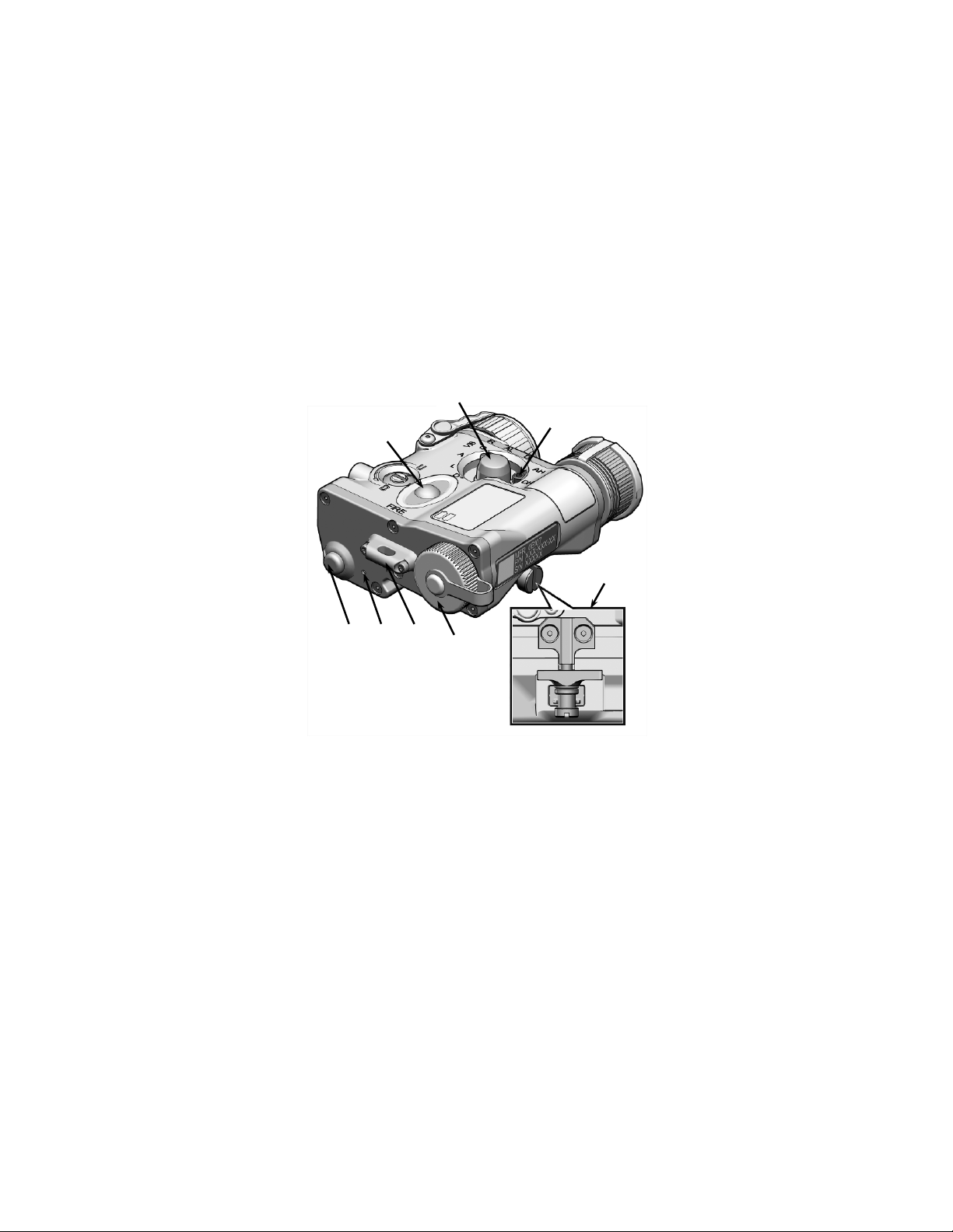
1.9 FEATURES AND CONTROLS
Figures 1-3 and 1-4 show features and controls for the
MIPIM. Table 1-3 provides a brief functional description of
each item. The “Key” column in Table 1-3 corresponds to
the label numbers in Figures 1-3 and 1-4.
Figure 1-3 Features and Controls (Sheet 1 of 2)
1
2
1-9
Page 22
10
11
12
13
16
17
1.9 FEATURES AND CONTROLS - Continued
15
14
Figure 1-4 Features and Controls (Sheet 2 of 2)
1-10
Page 23

Control/
Indicator
1
Tri-Function Lens
Serves the following three functions when
Laser.
illuminated.
4
Visible Aim Laser
Used to provide a precision aim point or
hours.
1.9 FEATURES AND CONTROLS - Continued
Key
Table 1-3 List of Features and Controls
Function
Cap
2
IR Illuminator
Focus Knob
3
IR Illuminator Used with night vision devices to provide
installed over the Tri-Laser Assembly:
a. Uses an Illuminator Diffuser to
spread the laser energy from the IR
Illuminator over an angle of
approximately 180 degrees,
allowing for illumination of a wider
area;
b. Prevents emission from the Visible
Aim Laser; and
c. Uses a Neutral Densit y Filter to
reduce scatter from the IR Aim
Used to vary the IR illumination beam
spread from flood to spot, based on the
range and size of the area to be
variable focused IR illumination of the
intended target area.
to positively identify targets at close range
during the day or night, without the need
of night vision devices. May also be used
for boresighting the MIPIM during daylight
1-11
Page 24

Control/
Indicator
5
IR Aim Laser
Used with night vision devices to provide
6
White Light
Provides a white light beam designed to
7
White Light Lens
When installed over the White Light
emission of white light energy.
8
Boresight
Used to bring the MIPIM aim lasers into
barrel of the weapon.
lockout position.
Compartment
DL123A batteries that power the MIPIM.
11
Tie-Down
Allows for the attachment of a lanyard to
12
LED Status
A Light Emitting Diode (LED) used to
Illuminator.
1.9 FEATURES AND CONTROLS - Continued
Table 1-3 List of Features and Controls - Continued
Key
a precision aim point or to mark targets.
Function
Illuminator
Cap
Adjusters
9
Safety Screw
Storage Location
10
Battery Cap /
Attachment Point
Indicator
1-12
allow for facial recognition at 25 meters.
Illuminator, reduces the risk of inadvertent
azimuth and elevation alignment with the
Allows for secure storage of the safety
screw after it has been removed from the
Provides secure housing for the two 3-volt
the MIPIM when used in the handheld
mode.
indicate when the MIPIM is emitting laser
and/or white light energy, when the
battery power is low, and displays the
pulse rate during programming of the IR
Page 25

Control/
Indicator
13
Remote Jack /
Provides an interface for the Remote
14
FIRE Button
Used to actively emit laser radiation
the position of the Mode Selector.
15
Mode Selector
Allows the user to select the desired
emit laser or white light energy.
crew allows for access to all Mode
Selector settings.
17
Rail Grabber
Secures the MIPIM to a weapon equipped
1.9 FEATURES AND CONTROLS - Continued
Table 1-3 List of Features and Controls - Continued
Key
Function
16
Jack Plug
Safety Screw
Bracket
Cable Switch. The MIPIM comes with a
remote jack plug installed to protect the
remote jack from debris and moisture.
and/or white light that corresponds with
mode of operation for the MIPIM. When
switched to O (OFF), the MIPIM will not
When installed in the lockout position, the
safety screw prevents the Mode Selector
from being turned to the high power laser
settings (i.e., AH, DH). Removal of the
safety s
with a MIL-STD-1913 rail.
1-13
Page 26

1-14
Page 27

CHAPTER 2
OPERATING INSTRUCTIONS
PREPARATION FOR USE AND INSTALLATION
2.1 PREPARATION FOR USE
Unpacking the Equipment
Open the soft carrying case and verify that all major
components listed in Table 1-2 are present. Check the
MIPIM to ensure the following additional items are included:
a. Battery Cap
b. Safety Screw
c. Remote Jack Plug
d. Tri-Function Lens Cap
e. White Light Lens Cap
If any of the major components or items listed above are
missing, seek guidance from the equipment issuing
authority.
Inspection of the Equipment
Before use, inspect all pieces of equipment for any damage
such as cracks, loose parts, faulty cables, or other visible
defects. If any damage or defects are noted, seek guidance
from the equipment issuing authority.
SECTION I
2-1
Page 28

2.2 BATTERY HANDLING
Battery Inspection
Before installation, inspect the 3-volt lithium batteries for any
cracks, dents, leakage, or bulging. Never install a defective
battery in the MIPIM.
Battery Installation
WARNING
Ensure the Mode Selector is turned to the O (OFF)
position before attempting to install, remove, or
replace batteries.
WARNING
Do not store the MIPIM with batteries installed.
NOTE
Proper battery orientation is clearly marked on the
label near the battery compartment.
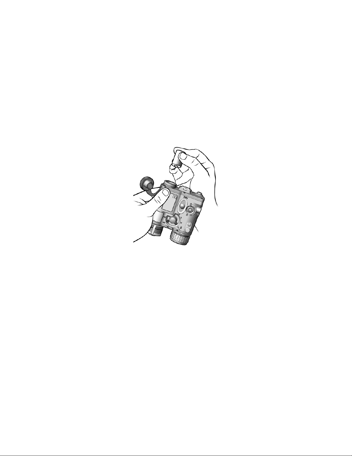
1. Unscrew the battery cap.
2. Tilt the MIPIM as shown in Figure 2-1 and install the first
DL123A lithium battery with the positive terminal facing in.
If necessary, gently shake the MIPIM to properly seat the
battery.
3. Install the second battery with the positive terminal facing
out.
4. Replace and tighten the battery cap.
2-2
Page 29
2.2 BATTERY HANDLING - Continued
Figure 2-1 Battery Installation
2-3
Page 30
MOUNTING
SCREW
RECOIL LUG
2.3 MOUNTING CONFIGURATIONS / PROCEDURES
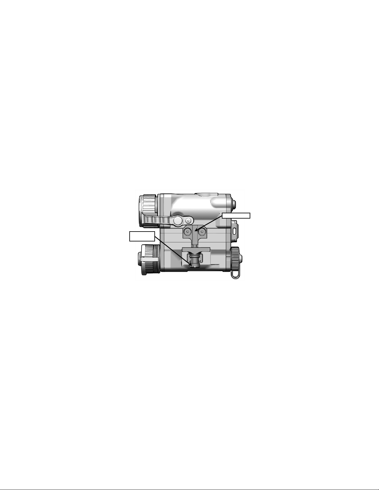
Rail Grabber Bracket
The MIPIM is equipped with an integral rail grabber bracket
(Figure 2-2) that is designed for direct attachment to
weapons with a MIL-STD-1913 rail.
Figure 2-2 Rail Grabber Bracket
Mounting Configurations
The MIPIM can be mounted on either the top or side rails of
the host weapon.
2-4
Page 31

2.3 MOUNTING CONFIGURATIONS / PROCEDURES -
Continued
Mounting Procedures
WARNING
Be sure the weapon is CLEAR and SAFE before
proceeding.
WARNING
Failure to properly secure the MIPIM to the rail
may lead to boresight repeatability and zeroing
issues. In extreme cases, the MIPIM could fall off
the rail, thereby exposing the operator or other
personnel to the MIPIM laser(s).
WARNING
The MIPIM may be placed at any position (forward
and aft) on the rail that is most convenient for the
operator. However, the entire length of the
mounting surface must be fully supported (in direct
contact) by the MIL-STD-1913 rail. If the MIPIM is
removed from the rail, the operator must make
note of the position at which it was boresighted or
zeroed, and return it to that same position in order
to ensure that zero is retained.
2-5
Page 32

2.3 MOUNTING CONFIGURATIONS / PROCEDURES -
Continued
1. Loosen the mounting screw on the rail grabber bracket
until the jaws have sufficient space to fit over the weapon
rail.
2. Hold the MIPIM with the laser apertures facing in the
direction of the muzzle of the weapon.
3. Position the MIPIM on the rail ensuring the recoil lug is
seated in the desired recoil groove of the rail.
4. While pushing down and forward on the MIPIM, turn the
mounting screw clockwise as tightly as fingers allow.
Take note of the screw slot in the mounting screw and
using an appropriate tool (e.g., screwdriver, multipurpose
tool, etc.), turn the mounting screw an additional 3/4 turn.
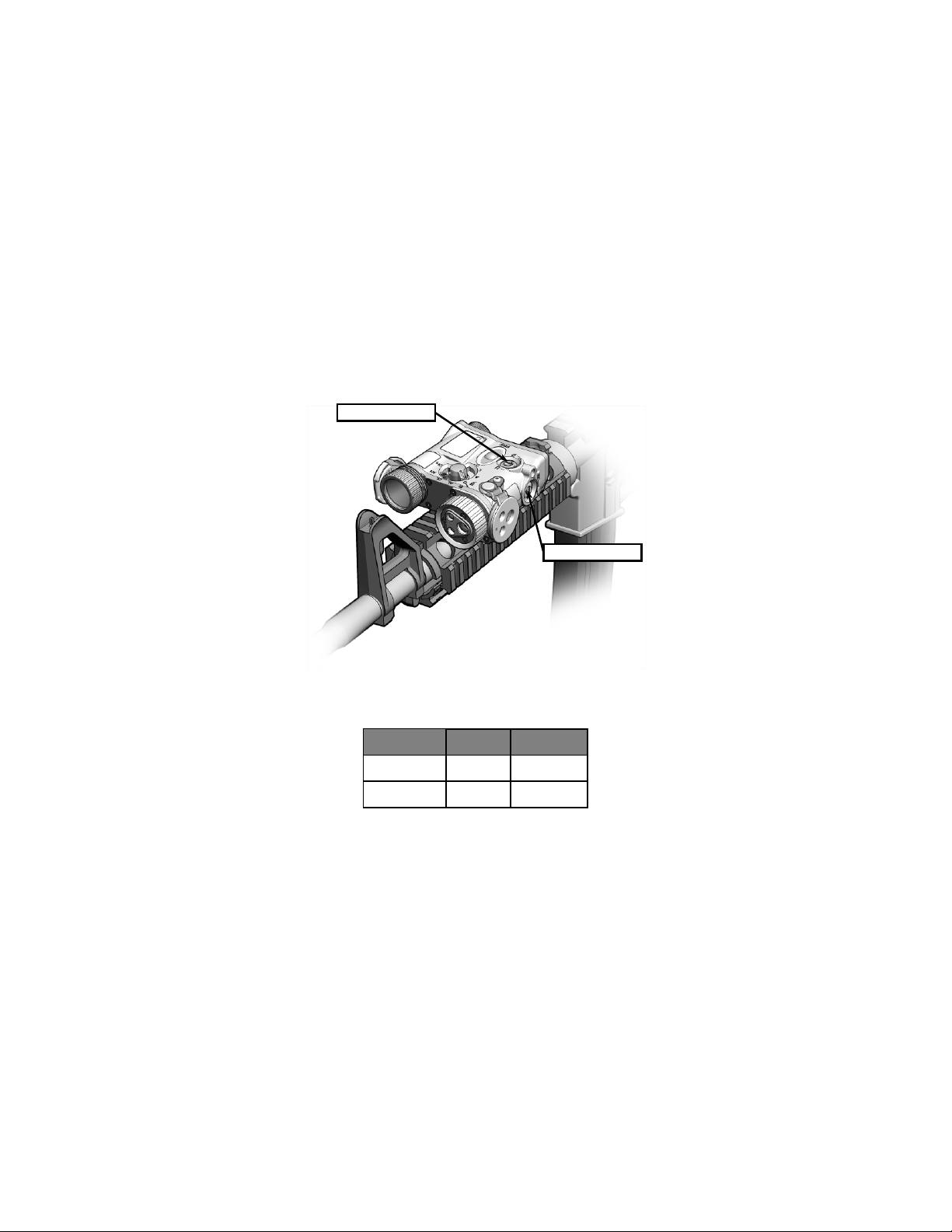
2.4 BORESIGHT ADJUSTERS
The MIPIM aim lasers are co-aligned. Therefore, a single
set of adjusters moves both aiming beams. Boresighting /
zeroing can be accomplished using either the Visible or IR
Aim Laser. Table 2-1 indicates the direction of adjuster
rotation and resultant shot group movement when the MIPIM
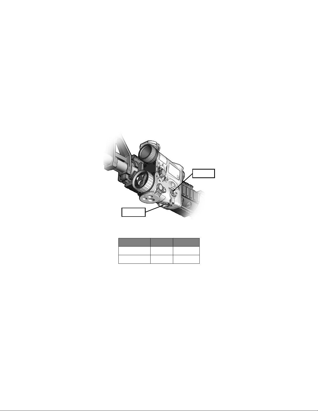
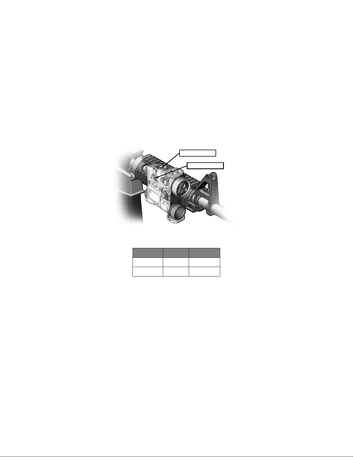
is top mounted. Tables 2-2 and 2-3 indicate the direction of
adjuster rotation and resultant shot group movement when
the MIPIM is side mounted (left / right).
NOTE
To minimize laser travel as a result of weapon
shock, it is good practice to place a positive load
on the adjusters by ending all boresight adjuster
rotations with an approximate 1/2 turn in a CCW
direction.
2-6
Page 33
Shot Group
Movement
Top Adjuster
CW
Up
Side Adjuster
CW
Left
2.4 BORESIGHT ADJUSTERS - Continued
TOP ADJUSTER
SIDE ADJUSTER
Figure 2-3 Boresight Adjusters (Top Mounted)
Table 2-1 Shot Group Movement (Top Mounted)
Adjuster Rotation
Elevation
Windage
CCW
CCW
Down
Right
2-7
Page 34
Shot Group
Movement
Side Adjuster
Windage
CW
CCW
Left
Right
Elevation
CCW
Up
BOTTOM
2.4 BORESIGHT ADJUSTERS - Continued
SIDE
ADJUSTER
ADJUSTER
Figure 2-4 Boresight Adjusters (Left Side Mounted)
Table 2-2 Shot Group Movement (Left Side Mounted)
Adjuster Rotation
Bottom Adjuster
2-8
CW
Down
Page 35
Shot Group
Movement
Top Adjuster
Elevation
CW
CCW
Up
Down
2.4 BORESIGHT ADJUSTERS - Continued
TOP ADJUSTER
SIDE ADJUSTER
Figure 2-5 Boresight Adjusters (Right Side Mounted)
Table 2-3 Shot Group Movement (Right Side Mounted)
Adjuster Rotation
Side Adjuster
Windage
CW
CCW
Right
Left
2-9
Page 36

2.5 BORESIGHTING PROCEDURES
The MIPIM incorporates a factory preset feature that may be
used to quickly bring the co-aligned lasers nearly parallel
with the barrel of the host weapon.
CAUTION
Do not force the adjusters beyond their end of
travel.
To establish this preset, rotate the Boresight Adjusters to the
full CCW end of travel, then rotate them back CW three
complete turns. Finally, place a positive load on the
adjusters by turning each adjuster 1/2 turn CCW.
The MIPIM may also be boresighted to the host weapon
using a Laser Borelight System (LBS). Table 2-4 provides
10m Target Offsets for this purpose. Refer to the latest
version of the LBS Operator Manual for boresighting
procedures.
The following abbreviations and their definitions apply to the
last two columns of Table 2-4:
L Left R Right
U Up D Down
VIS Visible Aim Laser IR IR (Infrared) Aim Laser
2-10
Page 37

M4/M4A1/
M16A4 MWS
VIS 1.8L / 1.5U
IR 1.8L / 2.6U
M4/M4A1/
M16A4 MWS
VIS 2.0L / 2.7D
IR 3.4L / 2.7D
M4/M4A1/
M16A4 MWS
VIS 3.4R / 0.7U
IR 4.7R / 0.7U
M249
Feed Tray
VIS 4.7L / 5.0U
M249
Short Barrel
Left Side
Forward Rail
VIS 7.5L / 4.5D
IR 8.5L / 4.5D
M249
Short Barrel
Right Side
Forward Rail
VIS 0.5R / 0.6D
IR 1.5R / 0.6D
M249
Feed Tray
VIS 2.4L / 3.2U
M249
Standard Barrel
Left Side
Forward Rail
VIS 3.5L / 4.5D
IR 4.5L / 4.5D
M249
Standard Barrel
Right Side
Forward Rail
VIS 3.3R / 1.5D
IR 4.6R / 1.5D
Feed Tray
VIS 2.0L / 1.3U
Left Side
VIS 3.7L / 7.6D
Right Side
Forward Rail
VIS 4.5R / 3.8D
IR 5.8R / 3.8D
M4/M4A1/M16A 4
MWS w/ M203
VIS 1.8L / 1.5U
IR 1.8L / 2.6U
M4/M4A1/M16A 4
VIS 2.2L / 2.7D
M4/M4A1/M16A 4
MWS w/ M203
VIS 2.8R / 0.0
IR 4.4R / 0.0
Table 2-4 Mounting Configurations and Weapon Offsets
Weapon Mount
Top Rail 300m
Range
Zeroed To
10m Boresight
Target Offset
Squares
25m Target Zero
Offset Squares
IR 2.0R / 1.0U
Short Barrel
Standard Barrel
M240B MG
M240B MG
M240B MG
MWS w/ M203
Left Rail 300m
Right Rail 300m
Cover Rail
400m
400m
400m
Cover Rail
400m
400m
400m
Cover Rail
Forward Rail
500m
500m
500m
Top Rail 300m
Left Rail 300m
Right Rail 300m
IR 4.7L / 6.2U
IR 2.4L / 4.5U
IR 2.0L / 2.8U
IR 4.8L / 7.6D
IR 3.4L / 2.7D
IR 3.5R / 5.0U
IR 4.2L / 3.0U
IR 2.0L / 7.0U
IR 6.0R / 11.5U
IR 2.0L / 11.7U
IR 1.0R / 5.0U
IR 7.3R / 7.3U
IR 2.2L / 5.7U
IR 2.3R / 6.9U
IR 3.0R / 17.0U
IR 5.2L / 13.7U
IR 1.0R / 1.0U
IR 3.6R / 8.0U
IR 4.2L / 4.5U
2-11
Page 38

2.6 ZEROING PROCEDURES
After establishing the factory preset or boresighting the
MIPIM / weapon combination, the MIPIM may be zeroed to
the weapon via live fire at a 25-meter range as described
below. Table 2-4 provides target offsets that must be
applied to the 25-meter zeroing target. Refer to Tables 2-1,
2-2, and 2-3 for adjuster rotation and resultant direction of
shot group movement.
NOTE
The Boresight Adjusters move the aiming beams
at the rate of 0.2 mrad per click. Two clicks = 1
box on a standard 25-meter zeroing target.
NOTE
Direct sunlight may hinder the ability of the user to
effectively see the Visible Aim Laser on the target.
a. On a 25-meter zeroing target, mark the designated
strike point and designated strike zone for the
weapon you are using (see Table 2-4).
b. Mount the target on an “E” silhouette or other
suitable surface at 25 meters.
c. Mount the MIPIM to the weapon.
d. Rotate the Mode Selector to the AL (IR AIM LOW)
position.
e. Activate the IR Aim Laser in continuous mode by
double-tapping the FIRE Button.
f. With the use of a night vision device, direct the IR
Aim Laser at the center of the target.
2-12
Page 39

2.6 ZEROING PROCEDURES - Continued
g. Fire a 3-round shot group and note the center of the
shot group relative to the designated strike point.
Retighten the integral rail grabber bracket.
h. Rotate the Boresight Adjusters to move the center of
the shot group to the designated strike point.
i. Fire another 3-round shot group and again observe
the center of the new shot group relative to the
designated strike point.
j. For all weapons except the M249, when 5 out of 6
consecutive rounds are in the designated strike
zone, the MIPIM / weapon combination is zeroed.
For the M249, the MIPIM / weapon combination is
zeroed when 5 out of 12 non-consecutive rounds are
within a 6cm square.
2-13
Page 40

The MIPIM will not operate.
of laser and white light energy.
VISIBLE
Class 3R
White Light Illuminator is
selected.
INFRARED (IR)
AIM LOW
Class 1
IR Aim Laser is selected in low
Class 1/3B
are both selected at low power.
AIM HIGH
Class 3B
IR Aim Laser is selected at
high power.
OPERATING INSTRUCTIONS
SECTION II
2.7 MODES OF OPERATION
Table 2-5 describes the modes of operation for the MIPIM.
Table 2-5 Modes of Operation
Position Mode Remarks
O
A
L
D
AL
DL
AH
DH
OFF
AIM
LIGHT
DUAL
(Class 3R)
DUAL LOW
DUAL HIGH
Class 3B
Prevents inadvertent emission
Visible Aim Laser is selected.
Visible Aim Laser is selected in
conjunction with the White
Light Illuminator.
power.
IR Aim Laser and IR Illuminator
IR Aim Laser and IR Illuminator
are both selected at high
power.
2-14
Page 41
2.7 MODES OF OPERATION - Continued
Mode Selection
WARNING
The Class 1 and 3R lasers (low power) described
in Table 2-5 may be used in force-on-force training
only if the opposing operators are beyond the
NOHD and NSHD values shown in Table i-1.
WARNING
The Class 3B lasers (high power) described in
Table 2-5 shall NOT be used in force-on-force
training.
WARNING
To prevent inadvertent activation of the laser(s) or
white light energy, the Mode Selector should be in
the O (OFF) position when not in use.
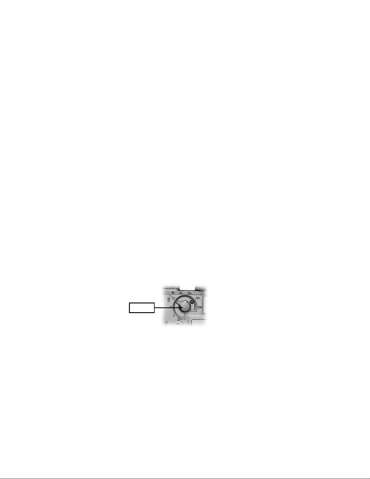
Modes of operation are accessed by turning the Mode
Selector to the desired position.
MODE
SELECTOR
Figure 2-6 Mode Selector
2-15
Page 42
SAFETY SCREW
2.7 MODES OF OPERATION - Continued
Safety Screw
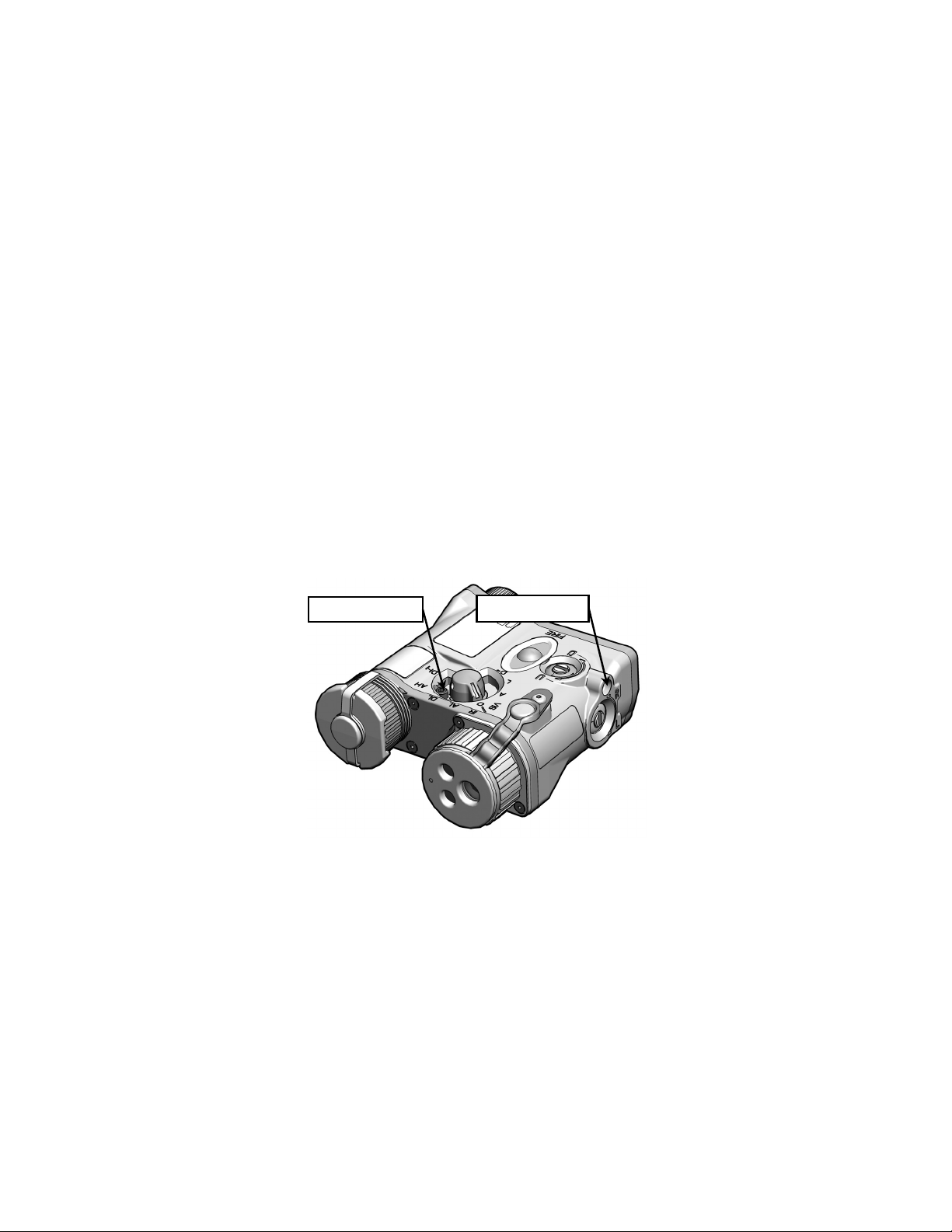
A removable safety screw installed in the lockout position
prevents the Mode Selector from being turned to the high
power laser settings (i.e., AH, DH). This configuration is
appropriate for a training environment or when the MIPIM is
being stored. A 3/32” hex head wrench is used to remove
the safety screw when, for tactical reasons, access to the
high power laser settings is desired (see paragraph 3.3.5).
The safety screw storage location allows for secure storage
of the safety screw after it has been removed from the
lockout position.
SAFETY SCREW
LOCKOUT POSITION
STORAGE LOCATION
Figure 2-7 Safety Screw Shown Lockout Position
2-16
Page 43

2.7 MODES OF OPERATION - Continued
Mode Activation
Once the mode of operation has been selected, the MIPIM
may be used in that mode by activating the system as
follows:
Momentary Operation. Pressing and holding the FIRE
Button operates the MIPIM in the selected mode. When the
button is released, the MIPIM turns off.
NOTE
The MIPIM is equipped with a shut-down feature
that will automatically turn off any laser (or the
White Light Illuminator) that has been activated for
five continuous minutes.
Continuous Operation. Pressing the FIRE Button twice in
rapid succession (double-tap) will turn the MIPIM on in the
selected mode. The MIPIM will remain on until the button is
pressed a third time (single-tap) or after five minutes of
continuous operation, whichever comes first.
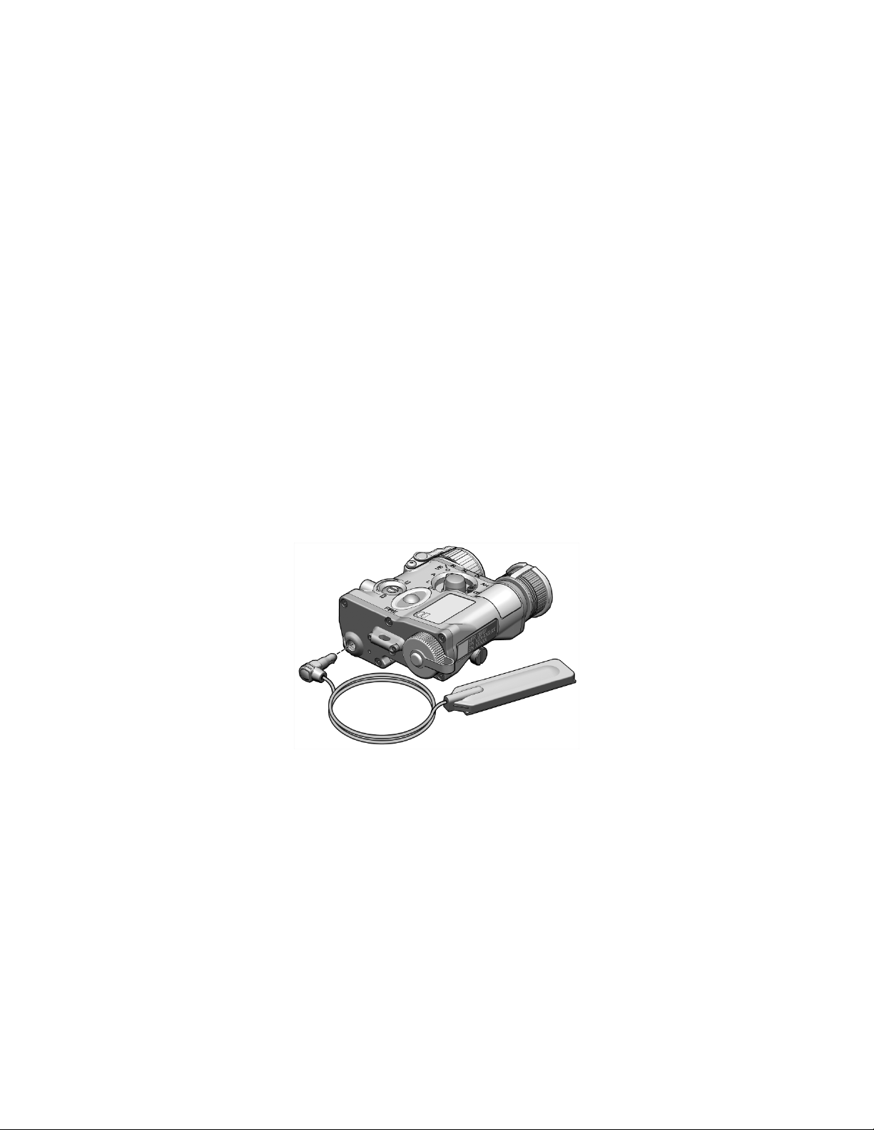
Remote Cable Switch. When installed, the Remote Cable
Switch may be used to provide the same functionality as the
FIRE Button and is operated in the same manner. The
Remote Cable Switch plugs into the remote jack as shown in
Figure 2-8. It is then secured to the weapon to best suit the
operator’s firing preference using the retaining straps and /
or hook and loop fastener tape.
2-17
Page 44
2.7 MODES OF OPERATION - Continued
CAUTION
When the Remote Cable Switch is plugged into
the remote jack, it automatically locks in place. To
remove it, pull back on the cable sleeve. Do not
remove the Remote Cable Switch by pulling on the
cable.
NOTE
The MIPIM comes with a jack plug installed in the
remote jack that must be removed and stored
before installing the Remote Cable Switch.
Figure 2-8 Installation of the Remote Cable Switch
2-18
Page 45

SPOT
FLOOD
2.8 USING THE LASERS
Laser modes of operation are selected and activated as
described in section 2.7.
Illuminator Beam Size
The IR illumination beam may be varied from flood to spot by
rotating the Illuminator Focus Knob as shown in Figure 2-9.
Figure 2-9 IR Illuminator Focus Knob
2-19
Page 46
TRI-FUNCTION
2.8 USING THE LASERS - Continued
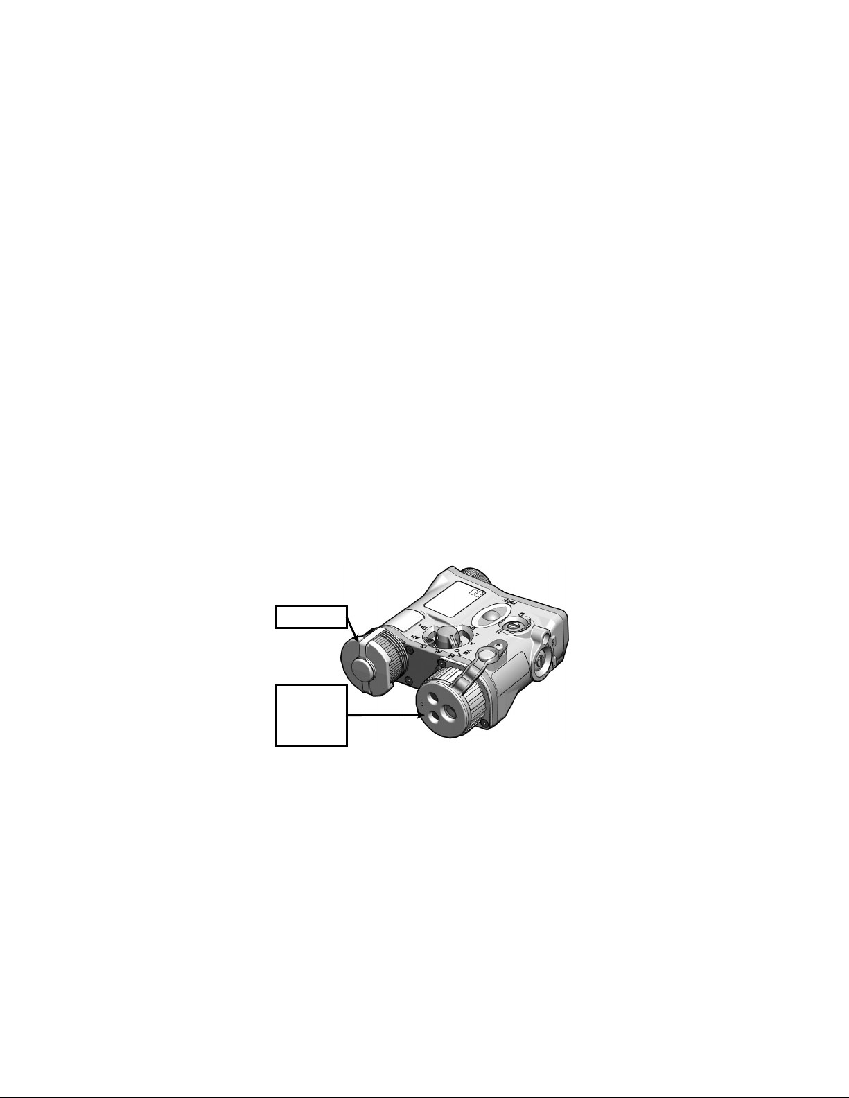
Tri-Function Lens Cap
To install the Tri-Function Lens Cap, stretch it out and over
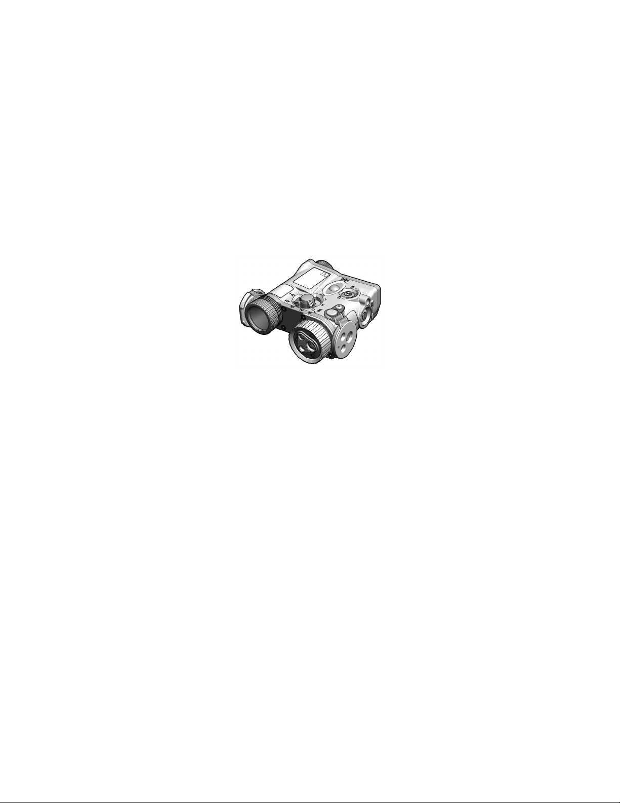
the front of the Tri-Laser Assembly so that it is snug and
firmly in place (see Figures 2-10 and 2-11). When installed,
the Tri-Function Lens Cap serves the following purposes:
a. Uses an Illuminator Diffuser to spread the laser
energy from the IR Illuminator over an angle
approaching 180 degrees, allowing for illumination of
a wider area. It is most effective when used in
conjunction with the IR Illumination Focus Knob
adjusted to the widest beam (flood) setting.
b. Prevents emission from the Visible Aim Laser.
c. Uses a Neutral Density Filter to reduce scatter from
the IR Aim Laser.
WHITE LIGHT
LENS CAP
LENS CAP OR
PATTERN
GENERATOR /
ILLUMIN ATOR
DIFFUSER
2-20
Figure 2-10 Lens Caps Installed
Page 47
2.8 USING THE LASERS - Continued
Figure 2-11 Lens Caps Uninstalled
Pattern Generator / Illuminator Diffuser Lens Cap
Five different Pattern Generator / Illuminator Diffuser Lens
Caps are supplied with the MIPIM for command and control
purposes. Each incorporates an Illuminator Diffuser and one
of five different Aim Laser Pattern Generators (i.e., circle,
square, triangle, T-shape, cross). Only one Pattern
Generator / Illuminator Diffuser Lens Cap may be used at a
time and may not be used in conjunction with the TriFunction Lens Cap. When installed, the lens cap serves the
following purposes:
2-21
Page 48

2.8 USING THE LASERS - Continued
a. Uses an Illuminator Diffuser over the IR Illuminator
identical to that described for the Tri-Function Lens
Cap.
b. Uses a Pattern Generator to project a specific
holographic design over the aim points of both the
Visible and IR Aim Lasers resulting in a 2.6m shape
at 300m (see Figure 2-12). Shapes are visible with
the naked eye if using the Visible Aim Laser and
with night vision devices if using the IR Aim Laser.
Figure 2-12 Pattern Generator Shapes
IR Illuminator Pulse Mode
In addition to momentary and continuous modes of
operation, the IR Illuminator may be programmed to operate
in pulse mode at either 1, 4, or 8 pulses per second.
Programming the IR Illuminator pulse rate is accomplished
as follows:
a. With the Mode Selector turned to the O (OFF)
position, hold down the FIRE Button.
b. Turn the Mode Selector to the desired pulse rate as
shown in Table 2-6. The rate will display on the LED
Status Indicator (the LED will flash green the same
number of times as the Illuminator pulse rate).
2-22
Page 49

Pulse Rate
Mode Selector Position
Continuous (no pulse)
AL
1 pulse per second
DL
4 pulses per second
AH*
8 pulses per second
DH*
2.8 USING THE LASERS - Continued
c. Release the FIRE Button. Successful programming
will be indicated by three orange flashes on the LED
Status Indicator. If programming was unsuccessful,
the LED Status Indicator will display a steady red
light for two seconds. The set pulse rate will remain
until it is programmed differently.
NOTE
To ensure successful programming, the Mode
Selector must be turned to the desired pulse rate
within 5 seconds of pressing the FIRE Button.
Table 2-6 IR Illuminator Pulse Rates
* The safety screw must be removed to program these pulse rates.
2.9 USING THE WHITE LIGHT ILLUMINATOR
White Light Illuminator modes of operation are selected and
activated as described in section 2.7. The White Light
Illuminator provides a beam of white light energy for visible
illumination of the intended target area. It provides for facial
recognition out to at least 25 meters.
2-23
Page 50
LED STATUS
INDICAT OR
2.8 USING THE WHITE LIGHT ILLUMINATOR Continued
Under certain operating conditions, particularly at night, it
may be desirable to help prevent inadvertent emission of
white light energy. The White Light Lens Cap is provided for
this purpose. To install the White Light Lens Cap, stretch it
out and over the front of the White Light Illuminator so that it
is snug and firmly in place. See Figures 2-10 and 2-11.
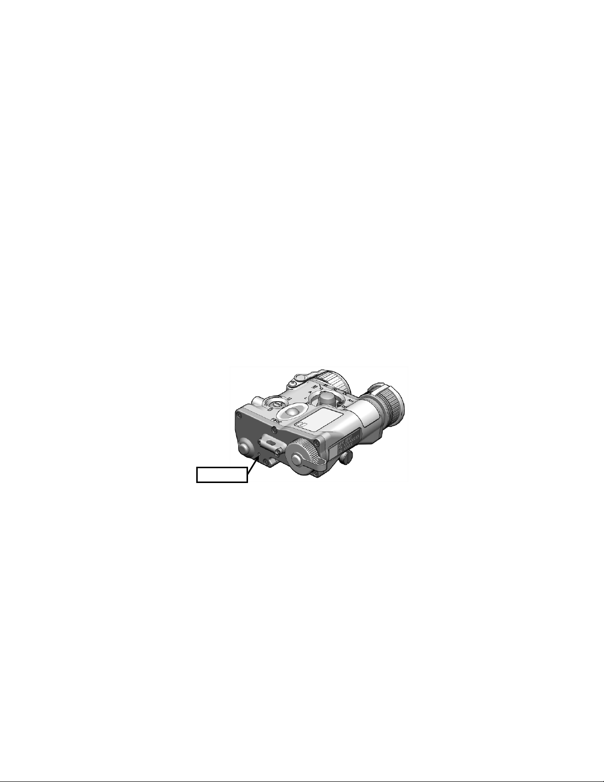
2.9 LED STATUS INDICATOR
A Light Emitting Diode (LED) is incorporated into the body of
the MIPIM that provides indicators as shown in Table 2-7.
2-24
Figure 2-13 LED Status Indicator
Page 51

Indicator
Color
Indicator
Rate
VIS LED
Status
IR LED
Status
VIS Laser or White Light
IR Laser(s) activated or
1 flash per
second
1 illuminator pulse per
second
4 flashes per
4 illuminator pulses per
8 flashes per
second
8 illuminator pulses per
second
RED
Steady
MIPIM low batteries
MIPIM low batteries
Steady green
seconds
Steady for 2
seconds
3 orange
2.9 LED STATUS INDICATOR - Continued
Table 2-7 LED Status Indicator
GREEN Steady
GREEN
GREEN
GREEN
GREEN/RED
RED
ORANGE
with 1 red
flash every 5
second
flashes
Illuminator activated
N/A
N/A
N/A
VIS Laser or White Light
Illuminator activated,
MIPIM battery power low
N/A IR programming failed
N/A IR programming successful
continuous IR illumination
IR Laser(s) activated,
MIPIM battery power low
second
2-25
Page 52

2-26
Page 53

Symptom
Malfunction
Corrective Action
1. Laser beam(s)
a. Software overload.
a. Cycle power.
b. Mode Switch is in the O
b. Turn Mode Switch to
c. Tri-Function Lens Cap is
emission.
c. If Visible Aim Laser
the Tri-Function Lens Cap.
d. Battery power is low.
d. Replace batteries.
e. Laser ports are obscured
e. Clean laser ports. See
f. Battery compartment and/or
f. Clean battery
See section 3.2.
CHAPTER 3
MAINTENANCE
MAINTENANCE AND TROUBLESHOOTING
3.1 TROUBLESHOOTING
The procedures below will help the operator correct some of
the basic problems that may arise with the MIPIM. If an
equipment malfunction occurs that is not listed, or the tests,
inspections, and corrective actions do not resolve the
problem, refer to section 3.4 for additional guidance.
appear weak or do
not come on when
activated.
Table 3-1 Troubleshooting Procedures
OFF position.
preventing Visible Aim Laser
by dirt, dust, or grime.
contacts corroded.
SECTION I
desired position. Activate by
pressing the FIRE button.
emission is desired, uninstall
section 3.2.
compartment and contacts.
3-1
Page 54

Symptom
Malfunction
Corrective Action
2. White Light
a. Software overload.
a. Cycle power.
b. Mode Switch is in the O
b. Turn Mode Switch to
pressing the FIRE button.
c. White Light Lens Cap is
c. Uninstall the White Light
d. Battery power is low.
d. Replace batteries.
e. Reflector assembly is
e. Clean reflector assembly.
f. Battery compartment and/or
f. Clean battery
See section 3.2.
3. Laser(s) and/or
a. Automatic turn-off feature
a. “Wake” the system by
b. Battery power is low.
b. Replace batteries.
c. Battery compartment
c. Clean battery
See section 3.2.
3.1 TROUBLESHOOTING - Continued
Table 3-1 Troubleshooting Procedures – Continued
Illuminator appears
weak or fails to
come on when
activated.
OFF position.
preventing white light
emission.
desired position. Activate by
Lens Cap.
White Light
Illuminator turn off
unexpectedly.
obscured by dirt, dust, or
grime.
contacts corroded.
has been activated.
and/or contacts corroded.
See section 3.2.
compartment and contacts.
pressing the FIRE button.
compartment and contacts.
3.2 PREVENTIVE MAINTENANCE
The operator should inspect the MIPIM before each use and
after it has been in extreme conditions, such as prolonged
exposure to intense temperatures. The following procedures
will prolong the life of the MIPIM and help ensure safe
operation.
WARNING
Prior to performing any inspection or maintenance
procedure, verify that batteries are not installed.
3-2
Page 55

3.2 PREVENTIVE MAINTENANCE - Continued
WARNING
Isopropyl alcohol is flammable and toxic. To avoid
injury, keep away from open fire and use in a well
ventilated area.
MIPIM Housing
Inspect the housing for any signs of damage including
cracks, missing parts, and any other visible defects. Rinse
thoroughly with water or mild soap and water, then dry with a
wiping rag. If necessary, clean around buttons, switches,
adjusters, and attachment points using fresh water and a
cotton swab.
Battery Compartment / Cap
Inspect the battery compartment for dirt, dust, or corrosion.
Dirt or debris that cannot be shaken loose from the battery
compartment may be removed using a cotton swab. Clean
the threaded portions of the battery cap and battery
compartment using a cotton swab dipped in isopropyl
alcohol. If necessary, clean battery contacts with a pencil
eraser or cotton swab dipped in isopropyl alcohol.
Periodically lubricate the battery cap o-ring with fluorinated
grease. Replace the o-ring if it becomes cut, nicked, or dried
out (see section 3.3).
Batteries
Inspect batteries for cracks, dents, leakage, or bulging. If a
battery shows signs of damage, remove and dispose of
properly. Replace as required.
3-3
Page 56

3.2 PREVENTIVE MAINTENANCE - Continued
Laser Ports and Reflector Assembly
Inspect the laser ports and Reflector Assembly Cover for
dirt, dust, and grime. Remove any large particles or loose
dirt using air or a lens brush. Fine cleaning of the optical
surfaces should be performed using an optical cloth and
cleaning solution. Avoid using excessive force as this may
scratch the lenses.
Remote Jack
Inspect the remote jack for corrosion, dirt and damage.
Gently remove any large particles of foreign matter and
clean the contacts using a cotton swab dipped in isopropyl
alcohol.
3.3 CORRECTIVE MAINTENANCE
The MIPIM has no internal parts or assemblies replaceable
by the operator or organizational level personnel. See
section 3.4 for guidance regarding maintenance and/or
repair actions beyond those described in this manual.
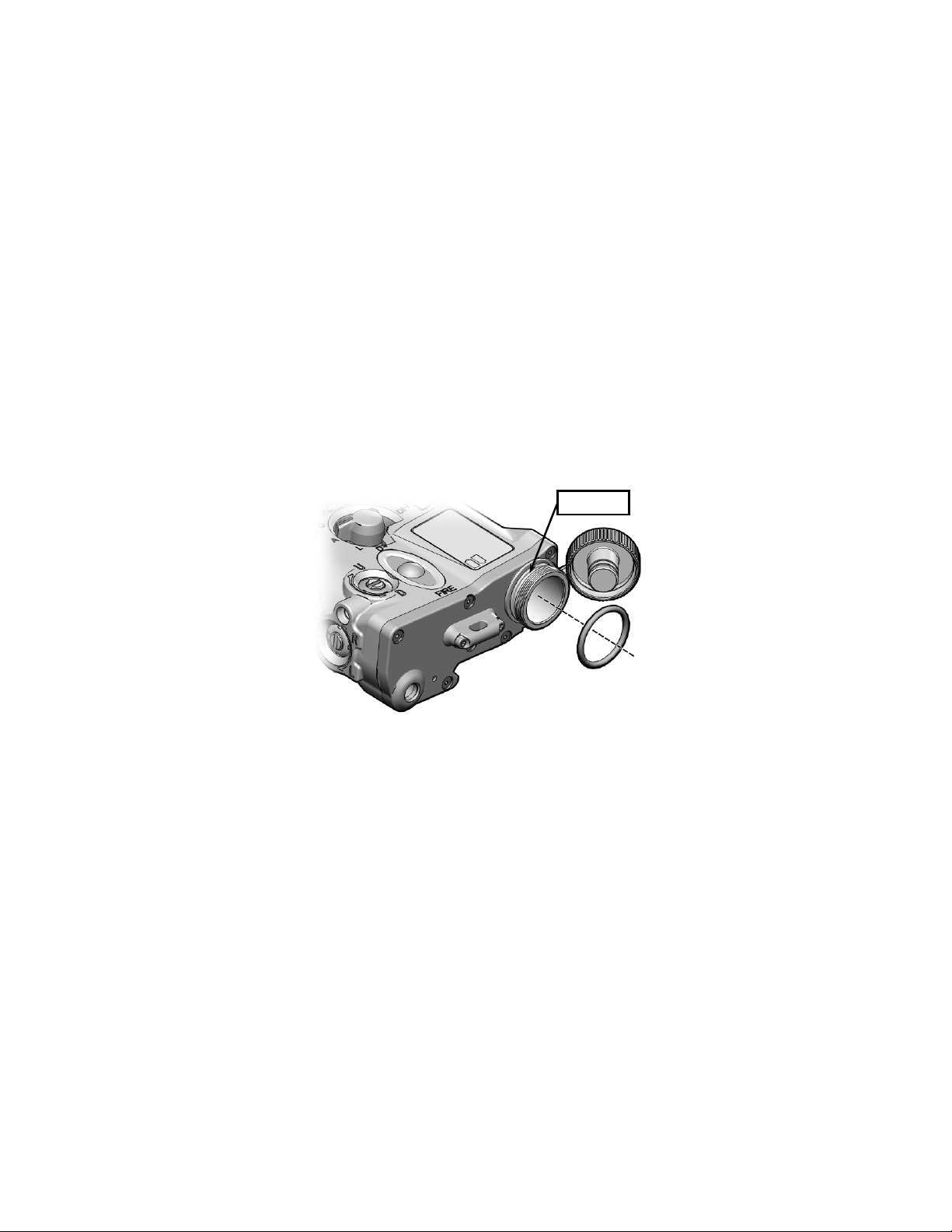
Replacing Battery Cap O-Ring
1. Unscrew the battery cap until it comes free of the battery
compartment threads.
2. Use the fingers of one hand to squeeze the battery cap
o-ring while simultaneously pushing it out of its retaining
groove. Grasp the o-ring with fingers of the other hand
and pull it off the battery compartment threads.
3-4
Page 57
RETAININ G
3.3 CORRECTIVE MAINTENANCE - Continued
3. Apply a light coating of fluorinated grease to the
replacement o-ring.
4. Stretch the replacement o-ring over the battery
compartment threads and slip it into its retaining groove.
5. Reinstall the battery cap and tighten.
GROOVE
Figure 3-1 Replacing the Battery Cap O-Ring
3-5
Page 58
BAT TER Y
3.3 CORRECTIVE MAINTENANCE - Continued
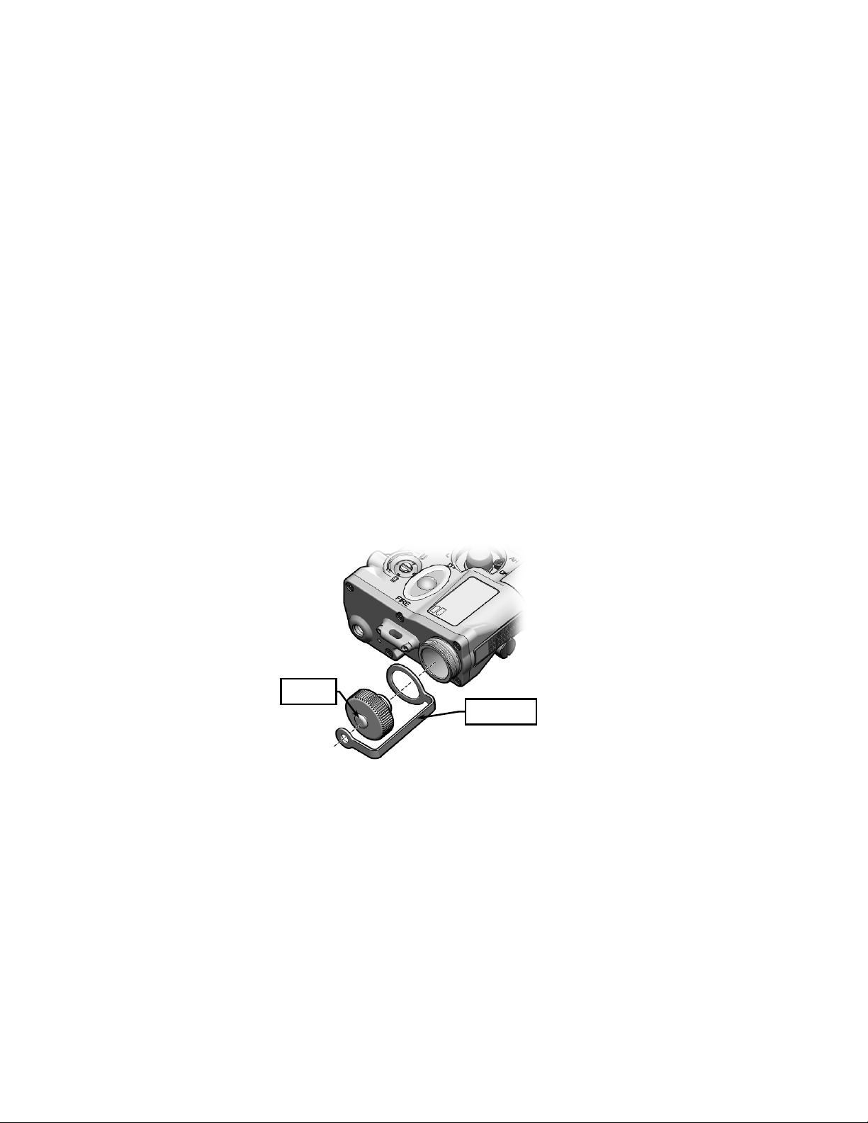
Replacing Battery Ca p / Battery Cap Lanyard
1. Turn the battery cap counterclockwise until it comes free
of the battery compartment threads.
2. Use the fingers of one hand to squeeze the battery cap
o-ring while simultaneously pushing it out of its retaining
groove. Grasp the o-ring with fingers of the other hand
and pull it off the battery compartment threads.
3. Simultaneously stretch and pull the larger eye of the
battery cap lanyard off the battery compartment threads.
4. Pull the smaller eye of the battery cap lanyard off the
battery cap post.
CAP POST
BAT TE RY C AP
LANYAR D
Figure 3-2 Replacing Battery Cap / Battery Cap Lanyard
3-6
Page 59

3.3 CORRECTIVE MAINTENANCE - Continued
5. Replace the battery cap and/or battery cap lanyard as
necessary.
6. Stretch smaller eye of the battery cap lanyard over the
post on the battery cap.
7. Simultaneously stretch and pull the larger eye of the
battery cap lanyard over the battery cap threads. Work
the lanyard until it is seated neatly in the groove closest to
the MIPIM housing.
8. Stretch the o-ring over the battery compartment threads
and slip it into its retaining groove.
9. Reinstall the battery cap and tighten.
Replacing Safety Screw
1. Remove safety screw by using a 3/32 inch hex head
wrench. Turn counterclockwise.
2. Install replacement safety screw in the lockout or storage
location. Using a 3/32 inch hex head wrench, turn
clockwise to tighten.
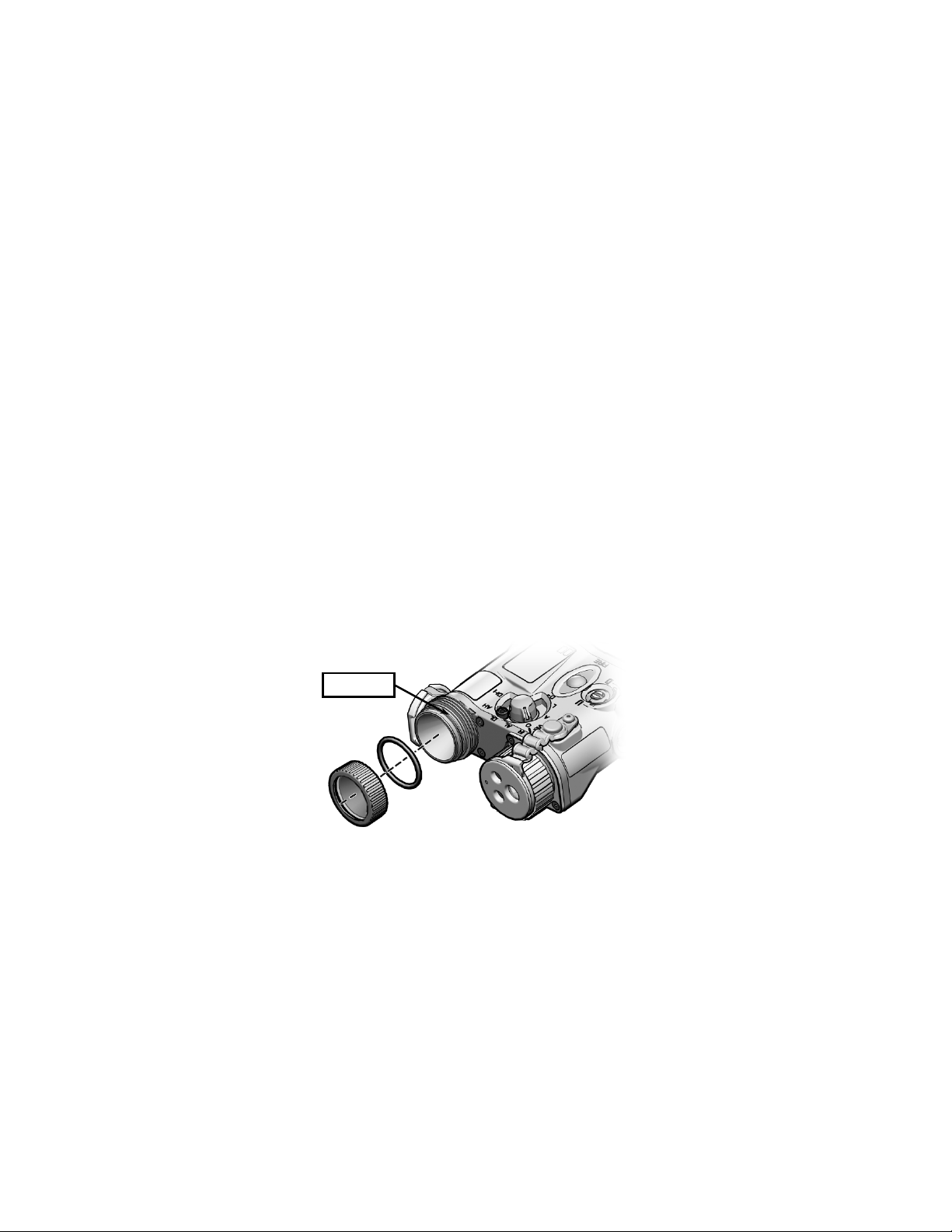
Replace Reflector Assembly Cover / O-Ring
NOTE
A new reflector assembly o-ring should be
installed whenever the Reflector Assembly Cover
is replaced.
1. Flip the White Light Lens Cap to the side of the White
Light Illuminator.
3-7
Page 60
GROOVE
CORRECTIVE MAINTENANCE - Continued
2. Remove the Reflector Assembly Cover by turning it
counterclockwise until it comes free of the MIPIM
housing.
3. Use the fingers of one hand to squeeze the reflector
assembly o-ring while simultaneously pushing it out of its
retaining groove. Grasp the o-ring with fingers of the
other hand and pull it off the reflector assembly.
4. Apply a light coating of fluorinated grease to the
replacement o-ring.
5. Stretch the replacement o-ring over the threaded portion
of the reflector assembly and slip it into its retaining
groove.
6. Reinstall the Reflector Assembly Cover; press down, and
rotate the reflector assembly clockwise to thread it onto
the MIPIM housing.
RETAININ G
Figure 3-3 Replacing Reflector Assembly O-Ring
3-8
Page 61
CORRECTIVE MAINTENANCE - Continued
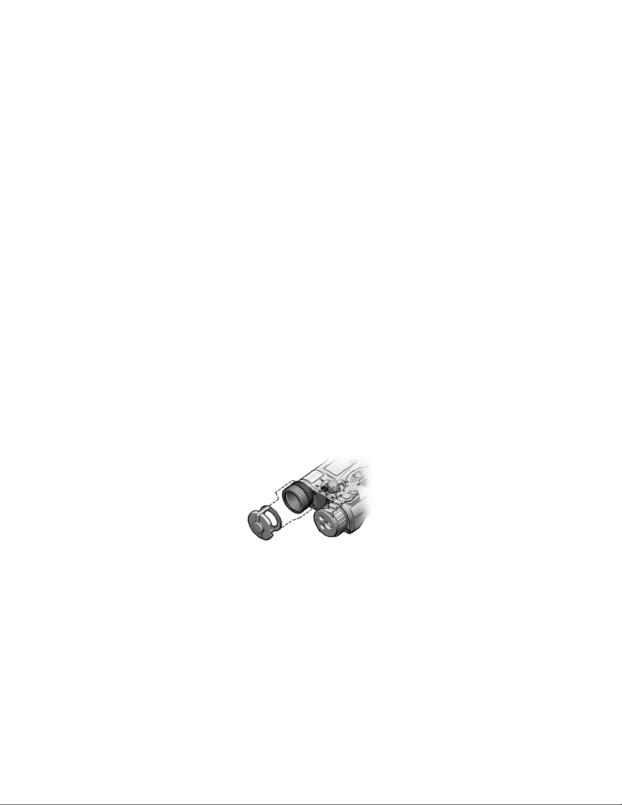
Replace White Light Lens Cap
NOTE
This procedure is easier to accomplish with the
Reflector Assembly Cover and reflector assem bly
o-ring removed.
1. If applicable, remove the old Lens Cap by pulling it off the
MIPIM housing.
2. Remove the Reflector Assembly Cover by turning it
counterclockwise until it comes free of the MIPIM
housing.
3. Use the fingers of one hand to squeeze the reflector
assembly o-ring while simultaneously pushing it out of its
groove. Grasp the o-ring with fingers of the other hand
and pull it off the reflector assembly.
4. Stretch the looped end of the replacement Lens Cap
around the reflector assembly.
Figure 3-4 Replacing White Light Lens Cap
3-9
Page 62
ATTACHMENT
FLAT SIDE OF LENS
CORRECTIVE MAINTENANCE - Continued
5. Work the looped end down the reflector assembly toward
the MIPIM housing, until it is seated neatly in the groove
closest to the MIPIM housing.
6. Reinstall the reflector assembly o-ring and Reflector
Assembly Cover (see CORRECTIVE MAINTENANCE,
Replace Reflector Assembly Cover / O-Ring).
7. Flip the Lens Cap up and over the Reflector Assembly
Cover.
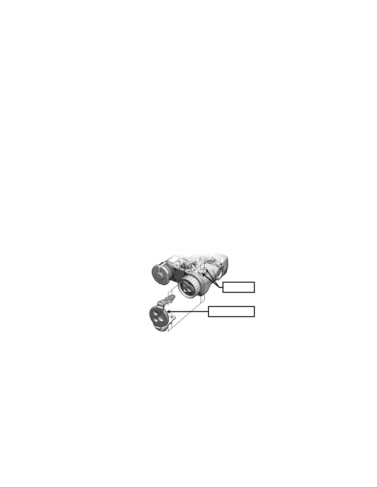
Replace Tri-Function or Pattern Generator / Illuminator
Diffuser Lens Cap
1. If applicable, pull both ends of the old lanyard off the Lens
Cap attachment points (see Figure 3-5). Attachment
points are located on both the top and bottom sides of the
MIPIM housing.
CAP FACING OUT
Figure 3-5 Replacing the Tri-Function Lens Cap
3-10
POINTS
Page 63

CORRECTIVE MAINTENANCE - Continued
2. With the new Lens Cap oriented as shown in Figure 3-5,
align the eyes in the longer end of the lanyard with the
attachment points on the bottom of the MIPIM. Work the
eyes over the attachment points, starting with the tancolored attachment point.
3. Lead the smaller end of the lanyard over the Tri-Laser
Assembly and work the eyes over attachment points on
the top of the MIPIM, starting with the tan-colored
attachment point.
3-11
Page 64

3-12
Page 65

SERVICE / PACKING AND UNPACKING
SECTION II
3.4 RETURN INSTRUCTIONS
For service, repair, or replacement, first e-mail
or call toll-free 1-877-744-4803.
To assist with determining if the item is repairable, the
following information will be requested:
a. Serial number of the defective item;
b. Thorough description of the malfunction, defect, or
damage; and
c. If known, an explanation as to how the malfunction,
defect or damage occurred.
If the item is determined to be Beyond Economical Repair,
follow applicable replacement procedures through your
Property Officer. If it is determined that the item is under
warranty, or should be returned for repair, a Return Material
Authorization (RMA) number will be provided.
When returning the MIPIM for service / repair, the following
procedures should be followed to prevent any additional
damage:
a. Be sure that the MIPIM is free of all contaminants
such as dirt or any other foreign material.
b. Remove batteries.
c. Place the MIPIM in the soft carrying case.
3-13
Page 66

3.4 RETURN INSTRUCTIONS - Continued
Place the item and a copy of the test report or detailed
description of the failure in a suitable packing container.
Mark the package with “Field Return” and the RMA number.
Ship via fastest, traceable, pre-paid means to:
L-3 Communications Corporation
Warrior Systems Division
Insight Operations
9 Akira Way
Londonderry, NH 03053
3.5 WARRANTY INFORMATION
The MIPIM is under warranty from defects in material and
workmanship for a minimum of one (1) year from the date of
manufacture. This warranty does not protect against
damage due to misuse, mishandling or battery leakage.
Additional warranty coverage may have been provided
through the contract or via subsequent contract extension.
Specific warranty terms can be obtained from your
procurement agent, Contracting Officer or L-3 Warrior
Systems, Insight.
3.6 NON-WARRANTY INFORMATION
Non-warranty repairs are subject to an evaluation fee. The
item will be tested and evaluated for failure, then customer
permission and payment terms are obtained prior to any
repairs being performed.
3-14
Page 67

APPENDIX A
END ITEM COMPONENTS AND REPAIR PARTS
SCOPE
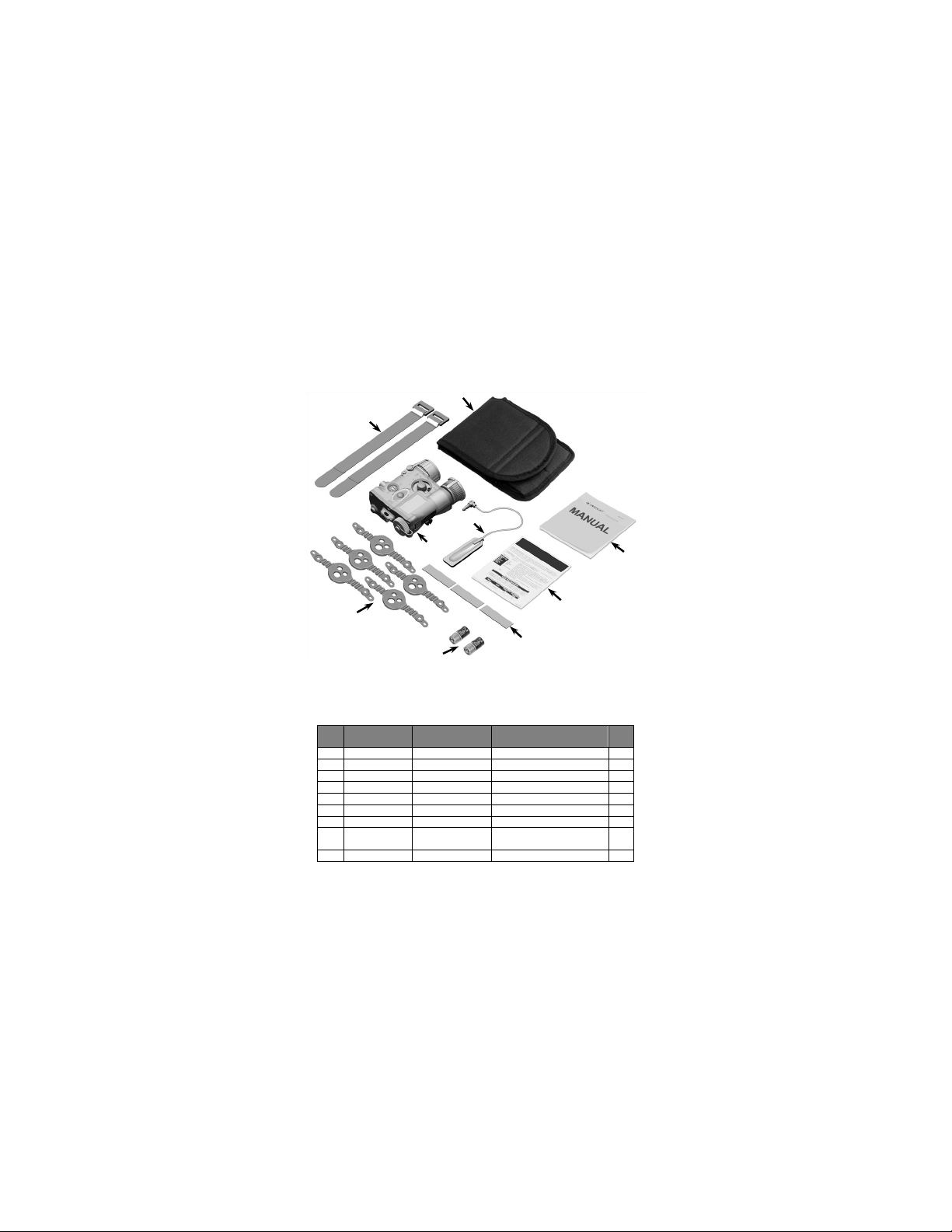
This Appendix lists end item components and repair parts
available for the MIPIM.
INTENTIONALLY LEFT BLANK
A-1
Page 68
ITEM
NO.
NATIONAL
STOCK NUMBER
PART
NUMBER
1
5340-01-455-0062
ITP-809
Retaining Straps
2
2
8105-01-368-6253
4B-949
Bag, Textile
1
3
N/A
MPMLED-TM-ITI
Operator Manual
1
4
N/A
MPMLED-QRG-ITI
Quick Reference Guide
1
5
8315-01-497-8154
ITP-044
Loop Tape
3 6 6135-01-559-9641
DL123ABK
Batteries, DL123
2
7
1240-01-585-0908
MPM-711-A2
Pattern Generator Kit
1
MIPIM Assembly (see Figure A-2
for parts breakdown)
9
5995-01-454-7124
ITP-053
Remote Cable Switch, 12”
1
1
8
6
9
SCOPE - Continued
2
7
5
Figure A-1 End Item Components
Table A-1 End Item Components / Repair Parts
8 N/A MPM-001-A11
A-2
DESCRIPTION QTY
3
4
1
 Loading...