

Page 1

MNVD-TM-ITI
OPERATOR MANUAL
FOR THE
Monocular Night Vision Device (MNVD)
Rev. 1 11 October 2011
Page 2

Page 3

SAFETY SUMMARY
GENERAL
This manual contains operating instructions and
maintenance procedures which may cause injury or death to
personnel, or damage to equipment if not properly followed.
Prior to performing any task, the WARNINGs, CAUTIONs
and NOTEs included in that task shall be reviewed and
understood.
DEFINITIONS
Highlights an essential operating or maintenance
procedure, practice, condition or statement, which,
if not strictly observed, could result in i njury to, or
death of, personnel or long term health hazards.
Highlights an essential operating or maintenance
procedure, practice, condition or statement, which,
if not strictly observed, could res ult in damage to,
or destruction of, equipment or loss of mission
effectiveness.
Highlights an essential operating or maintenance
procedure, condition or statement.
WARNING
CAUTION
NOTE
i
Page 4

SAFETY PRECAUTIONS
The following general safety precautions supplement the
specific WARNINGs, CAUTIONs and NOTEs that appear
elsewhere in this manual.
WARNING
The Infrared (IR) LED Illuminator is detectable by
an enemy using night vision devices. Detecti on is
easier in smoky, foggy, or rainy conditions. To
reduce the risk of detection by an enemy using
night vision devices, avoid prolonged activation of
the IR LED Illuminator.
WARNING
Emission of stray light from the eyepiece (even
with eyecup installed) may be detectable by the
enemy.
WARNING
Do not touch, ingest, or inhale particles or
fragments of a broken objective lens. Lens
contains material that may cause irritation t o eyes,
skin, upper and lower respiratory tracts, or
gastrointestinal tract. If contacted, flush eyes or
skin with large amounts of water. If ingested, DO
NOT induce vomiting. Rinse mouth with water
and give victim 2-4 cupfuls of milk or water.
Fragments of lens may be sharp enough to cut
personnel if touched.
ii
Page 5

WARNING
Remove the MNVD from the weapon before
inspecting, cleaning, or performing other
maintenance functions.
WARNING
• Do not short circuit, puncture, incinerate, or
disassemble battery.
• Do not attempt to recharge battery.
• Prior to us e, inspect battery f or cracks, dents,
leakage, or bulging. Never install a defective
battery in the MNVD.
WARNING
Lithium batteries can explode or cause burns if
disassembled, shorted, recharged, exposed to
water, fire, or high temperatures (above 100°C or
212°F). Do not place loose batteries in a pocket
or other container containing metal objects. Do
not store batteries with hazardous or combustible
materials. Store in a cool, dry, ventilated area.
WARNING
Use of off-brand batteries poses a risk of fire or
explosion. Ensure that only a 1.5V AA battery
produced by a well-known batt ery manufacturer is
installed in the MNVD. These batteries are
specifically designed for use in high perform ance,
high-drain devices, and contain built-in fault and
heat protection features.
iii
Page 6

CAUTION
Do not ship or store the MNVD with the battery
installed.
CAUTION
Pointing the MNVD at the sun without the lens
cover installed may damage internal imaging
components.
CAUTION
The coating on the demist shiel d may be damaged
if cleaned while wet. Clean the demist s hield only
when dry and using dry lens tissue.
CAUTION
Use of acetone or gun cleaning agents containing
perchloroethylene or methylene chloride may
permanently damage the MNVD.
iv
Page 7

TABLE OF CONTENTS
SAFETY SUMMARY ....................................................................... i
TABLE OF CONTENTS ................................................................. v
LIST OF FIGURES ....................................................................... vii
LIST OF TABLES ......................................................................... vii
CHAPTER 1 ...................................................................................... 1-1
INTRODUCTION ......................................................................... 1-1
SECTION I .............................................................................. 1-1
GENERAL INFORMATION ............................................... 1-1
1.1 SCOPE .................................................................. 1-1
1.2 MODEL NUMBER AND EQUIPMENT NAME ...... 1-2
1.3 MANUFACTURER ................................................ 1-2
1.4 PURPOSE OF EQUIPMENT ................................ 1-2
1.5 ABBREVIATIONS AND ACRONYMS .................. 1-2
SECTION II ............................................................................. 1-3
EQUIPMENT DESCRIPTION ........................................... 1-3
1.6 SYSTEM DESCRIPTION ...................................... 1-3
1.7 TECHNICAL SPECIFICATIONS .......................... 1-4
1.8 MAJOR COMPONENTS ....................................... 1-5
CHAPTER 2 ...................................................................................... 2-1
1.9 FEATURES AND CONTROLS ............................. 1-8
OPERATING INSTRUCTIONS ................................................... 2-1
SECTION I .............................................................................. 2-1
PREPARATION FOR USE ............................................... 2-1
2.1 PREPARATION FOR USE ................................... 2-1
2.2 BATTERY HANDLING .......................................... 2-2
2.3 HEADMOUNT ASSEMBLY .................................. 2-3
2.4 WEAPON MOUNTING INSTRUCTIONS ........... 2-11
2.5 LENS ACCESSORIES ........................................ 2-14
SECTION II ........................................................................... 2-16
OPERATING INSTRUCTIONS ....................................... 2-16
2.6 MODES OF OPERATION ................................... 2-16
2.7 IR LED ILLUMINATOR ....................................... 2-17
2.8 GAIN (CONTRAST) ............................................ 2-18
2.9 FOCUS ................................................................ 2-18
2.10 DIOPTER ADJUSTMENT ................................. 2-19
2.11 STARTUP PROCEDURES ............................... 2-19
v
Page 8

TABLE OF CONTENTS – Continued
CHAPTER 3 ...................................................................................... 3-1
MAINTENANCE .......................................................................... 3-1
SECTION I .............................................................................. 3-1
OPERATOR MAINTENANCE ........................................... 3-1
3.1 TROUBLESHOOTING PROCEDURES ............... 3-1
3.2 INSPECTION / CLEANING................................... 3-3
3.3 CORRECTIVE MAINTENANCE PROCEDURES 3-5
SECTION II ............................................................................. 3-7
SERVICE / PACKING AND UNPACKING ........................ 3-7
3.4 SERVICE / REPAIR .............................................. 3-7
3.5 WARRANTY INFORMATION ............................... 3-8
APPENDIX A ................................................................................... A-1
APPENDIX B ................................................................................... B-1
3.6 NON-WAR RANTY INFOR MAT ION ...................... 3-8
REPAIR PARTS LIST ................................................................ A-1
ACCESSORIES .......................................................................... B-1
vi
Page 9

LIST OF FIGURES
Figure 1-1 Headmounted MNVD ..................................................... 1-1
Figure 1-2 Major Components
Figure 1-3 Features and Controls
Figure 2-1 Battery Installation
Figure 2-2 Low Battery Indicator
Figure 2-3 Headmount Assembly
Figure 2-4 Headmount Adapter Installation
Figure 2-5 Mounting to Headmount Assembly
Figure 2-6 Fore / Aft Release Button
Figure 2-7 Adjustment Knob
Figure 2-8 Weapon Mount Assembly
Figure 2-9 Weapon Mount Assembly Installation
Figure 2-10 Mounting the MNVD
Figure 2-11 MNVD Eyecups
Figure 2-12 IR LED Illuminator Indicator
Figure 3-1 Neck Cord Replacement
Figure A-1 End Item Components
Figure A-2 MNVD Assembly
LIST OF TABLES
Table 1-1 Technical Specifications .................................................. 1-4
Table 1-2 List of Major Components
Table 1-3 List of Features and Controls
Table 2-1 Field of View and Positioning Adjustments
Table 2-2 Mode Switch Operation
Table 3-1 Troubleshooting Procedures
Table A-1 List of End Item Components
Table A-2 List of Repair Parts
Table B-1 List of Accessories
......................................................... 1-5
.................................................... 1-8
.......................................................... 2-2
...................................................... 2-3
.................................................... 2-4
..................................... 2-6
................................ 2-7
............................................... 2-8
............................................................ 2-9
............................................ 2-11
.......................... 2-12
................................................... 2-13
.......................................................... 2-15
....................................... 2-18
................................................ 3-6
.................................................. A-1
........................................................... A-3
............................................... 1-6
.......................................... 1-9
................... 2-10
................................................. 2-17
........................................... 3-1
......................................... A-2
......................................................... A-3
......................................................... B-1
vii
Page 10

Page 11

CHAPTER 1
INTRODUCTION
SECTION I
GENERAL INFORMATION
Figure 1-1 Headmounted MNVD
1.1 SCOPE
This manual is intended for use by operators of the
Monocular Night Vision Device (MNVD). It provides a
system description, operational procedures, and
maintenance responsibilities. Complete familiarization with
this manual prior to using the equipment will ensure safe
operation and maxi mum effectiv eness of the MNVD.
1-1
Page 12

1.2 MODEL NUMBER AND EQUIPMENT NAME
cm
Centimeter
g
Gram
I2
Image Intensifier
ITAR
International Traffic in Arms Regulations
LED
Light Emitting Diode
mm
Millimeter
MNVD
Monocular Night Vision Device
RMA
Return Material Authorization
TBD
To Be Determined
V
Volt
245620, Monocular Night Vision Device (MNVD)
1.3 MANUFACTURER
L-3 Communications Corporation
Warrior Systems Division
Insight Operations
9 Akira Way
Londonderry, NH 03053 USA
1.4 PURPOSE OF EQUIPMENT
The MNVD allows for observation under adverse conditions
including light rain, smoke, light snow, and low light to total
darkness.
1.5 ABBREVIATIONS AND ACRONYMS
Abbreviations and acronyms used in this manual are listed
as follows:
IR Infrared
NSN National Stock Number
1-2
Page 13

EQUIPMENT DESCRIPTION
SECTION II
1.6 SYSTEM DESCRIPTION
The MNVD is a portable, battery operated night vision device
with an integrated IR light source. It can be used as a
handheld device or may be mounted to a weapon, helmet, or
headmount assembly.
When used in the normal operating mode (ON), the MNVD
amplifies available ambient light to allow for observation
under adverse conditions including light rain, smoke, light
snow, and low light conditions. When used in the IR mode,
the MNVD generates its own light with an integrated IR LED
Illuminator to allow for observation, map reading, etc. even in
complete darkness.
The MNVD is a ruggedized system designed for operation in
battlefield environments.
1-3
Page 14

1.7 TECHNICAL SPECIFICATIONS
WEIGHT AND DIMENSIONS
Weight
< 14.1 ounces (400 g)
(with standard eyecup)
Width
2.8 inches (7.1 cm)
Height
2.4 inches (6.1 cm)
POWER AND PERFORMANCE
Battery
One 1.5V AA lithium battery
Battery Life 1
> 15 hours
Magnification
1x
Field of View
40° (± 2°)
Objective Focus
9.8 inches (25cm) to infinity
Diopter Adjustment
+2 to -6
Immersion
1 meter for 30 minutes
Operating Temperature
-60°F (-51°C) to 120°F (49°C)
Storage Temperature
-60°F (-51°C) to 185°F (85°C)
Table 1-1 provides technical specifications for the MNVD.
Table 1-1 Technical Specifications
Length
1
Performance will vary depending on actual environmental and
6.5 inches (16.5 cm)
atmospheric conditions.
1-4
Page 15
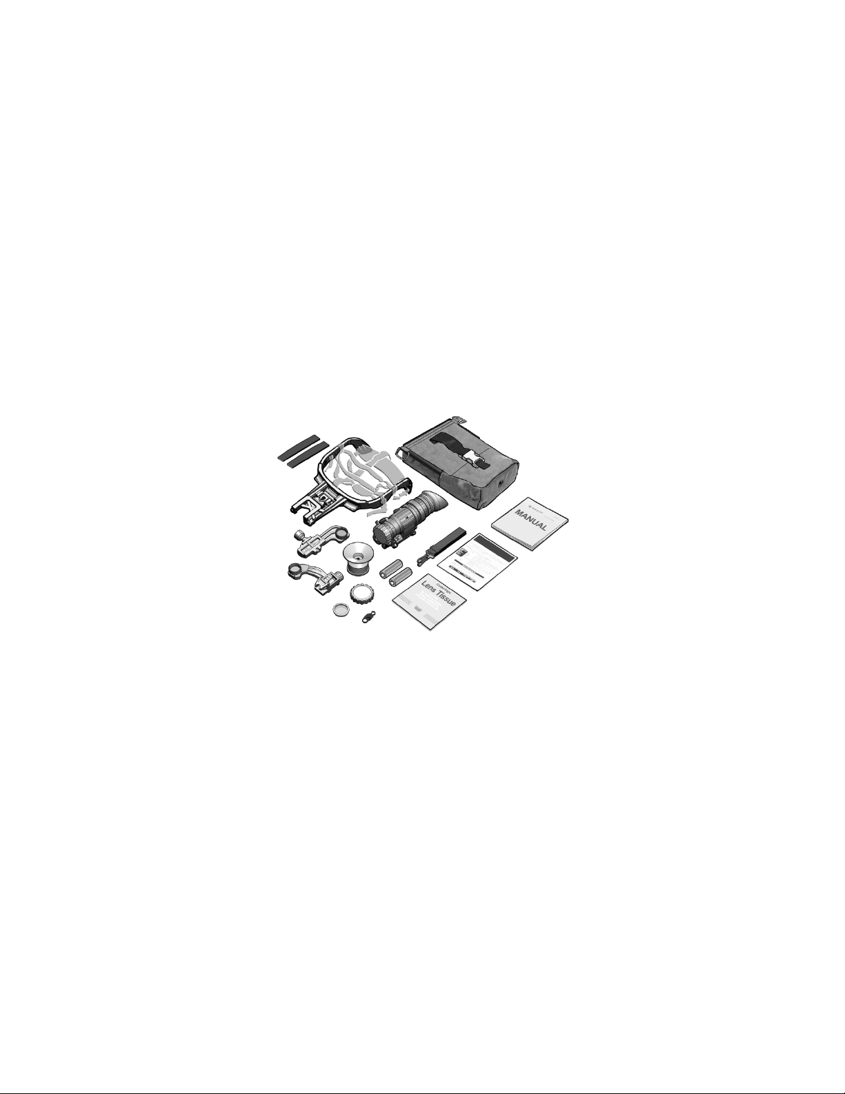
1.8 MAJOR COMPONENTS
1
2
8
10
15
14
The MNVD syst em includes the components shown in Figure
1-2. Table 1-2 provides a brief functional description of each
item. The “Key” column in Table 1-2 corresponds to the
label numbers in Figure 1-2.
3
13
11
12
5
9
7
6
4
Figure 1-2 Major Components
1-5
Page 16

1.8 MAJOR COMPONENTS – Continued
Major
Component
1
Brow Pads
Used on the headmount assembly to
2
Headmount
Worn on the head to permit hands-free
3
Soft Carrying
Case
Protects the MNVD and accessories
while in a field environment.
4
Operator Manual
Provides detailed ope rating and
MNVD.
Guide
instructions for the MNVD.
MNVD.
8
Sacrificial
Protects the objective lens from
damaged.
9
Demist Shield
Protects the eyepiece from becoming
prevents fogging of the eyepiece.
Key
Table 1-2 List of Major Components
Function
provide maximum comfort and best fit.
Assembly
operation of the MNVD.
maintenance procedures specific to the
5
Quick Reference
6
Lens Tissue
7
Retainer Cord May be tied to the MNVD and clipped to
Provides at-a-glance op era ti n g
Used to clean the optical surfaces of the
the operator to secure the MNVD when
not in use.
Window
becoming scratched or oth er wi se
scratched or otherwis e dam ag ed and
1-6
Page 17

1.8 MAJOR COMPONENTS – Continued
Major
Component
10
Headmount
Allows the MNVD to be installed on the
11
Weapon Mount
Allows the MNVD to be mounted to
1913 rail.
12
Eyecup,
Reduces emission of stray light from the
weapon-mounted configuration.
device with integrated IR light source.
Battery (2)
across the shoulder for ease of carrying.
Table 1-2 List of Major Components – Continued
Key
Function
Adapter
Assembly
Shuttered
13
MNVD Assembly
14
AA Lithium
15
Shoulder Strap
headmount assembly or a suitably
configured helmet.
weapons equipped wit h a MIL-STD-
eyepiece when the MNVD is used in a
A portable, battery operated night vision
Provides power to the MNVD.
Allows the soft carrying case to be slung
1-7
Page 18
1.9 FEATURES AND CONTROL S
2
5
7
8
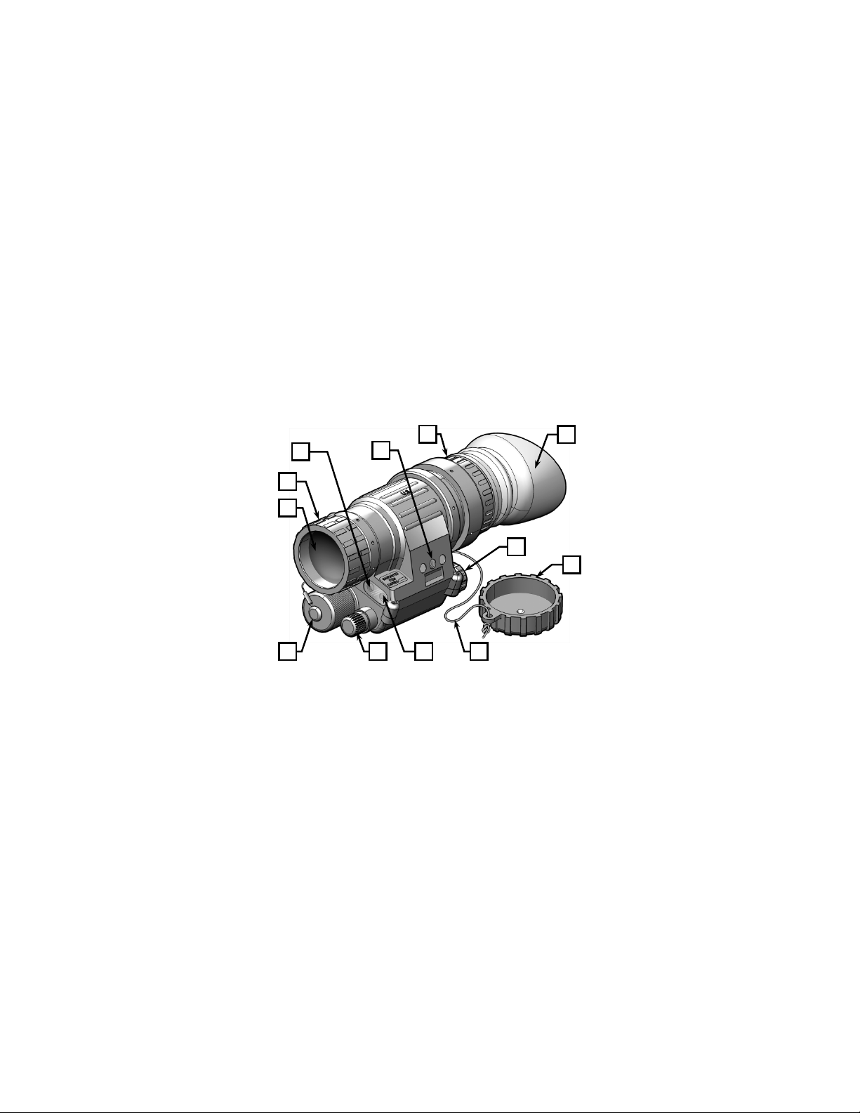
Figure 1-3 shows features and controls for the MNVD. Table
1-3 provides a brief functional description of each item. The
“Key” column in Table 1-3 corresponds to the label numbers
in Figure 1-3.
3
1
4
6
1-8
11 12
10 9
Figure 1-3 Features and Controls
Page 19

1.9 FEATURES AND CONTROLS – Continued
Major
Component
1
Objective Lens
Collects available light within the viewed
2
Focus Ring
Used to focus the MNVD from 9.8
inches (25cm) to infinity.
3
High Light Sensor
Detects ambient light conditions so that
damaging internal components.
assembly.
operator.
6
Eyecup
Assists in positioning the MNVD relative
eyepiece.
7
Mode Switch
A 3-position switch used to turn the
MNVD on in a selected operating mode.
8
Lens Cover
Protects the objective lens and internal
the MNVD is not in use.
Key
Table 1-3 List of Features and Controls
Function
4
Mounting
Interface
5
Diopter Adjuster
scene and focuses it onto the input
surface of an image intensifier (I
2
) tube.
the I2 tube will be automatically shut off
if conditions are so bright as to risk
Provides female threading to accept the
headmount adapter and weapon mount
Used to focus the eyepiece lens to
compensate for the visual acuity of the
to the operator’s eye in handheld and
headmounted configurations. Reduces
emission of stray light from the
imaging components and prevents glare
or reflection off the objective lens when
1-9
Page 20

1.9 FEATURES AND CONTROLS – Continued
Major
Component
9
Neck Cord
Holds the objective lens cover captive to
10
IR LED
Used to provide a supplementary light
darkness.
11
Gain Control
Knob
Used to adjust the gain (contr ast) of the
viewed image.
Compartment
AA battery that powers the MNVD.
Table 1-3 List of Features and Controls – Continued
Key
Function
the MNVD. Allows for the MNVD to be
worn around the neck during periods of
nonuse.
12
1-10
Illuminator
Battery Cap /
source in conditions of extreme
Provides secure housing for the single
Page 21

CHAPTER 2
OPERATING INSTRUCTIONS
SECTION I
PREPARATION FOR USE
2.1 PREPARATION FOR USE Unpacking the Equipment
Open the soft carrying case and verify that all major
components listed in Table 1-2 are present. Check the
MNVD to ensure the following additional items are included:
a. Eyecup
b. Lens Cover
c. Battery Cap
d. Neck Cord
If any of the major components or items listed above are
missing, seek guidance from the equipment issuing
authority.
Inspection of the Equipment
Before use, inspect all pieces of equipment for any damage
such as cracks, loose parts, faulty cables, or other visible
defects. If any damage or defects are noted, seek guidance
from the equipment issuing authority.
2-1
Page 22
2.2 BATTERY HANDLING Battery Inspection
Before installation, inspect the battery for any cracks, dents,
leakage, or bulging. Never install a defective battery in the
MNVD.
Battery Installation
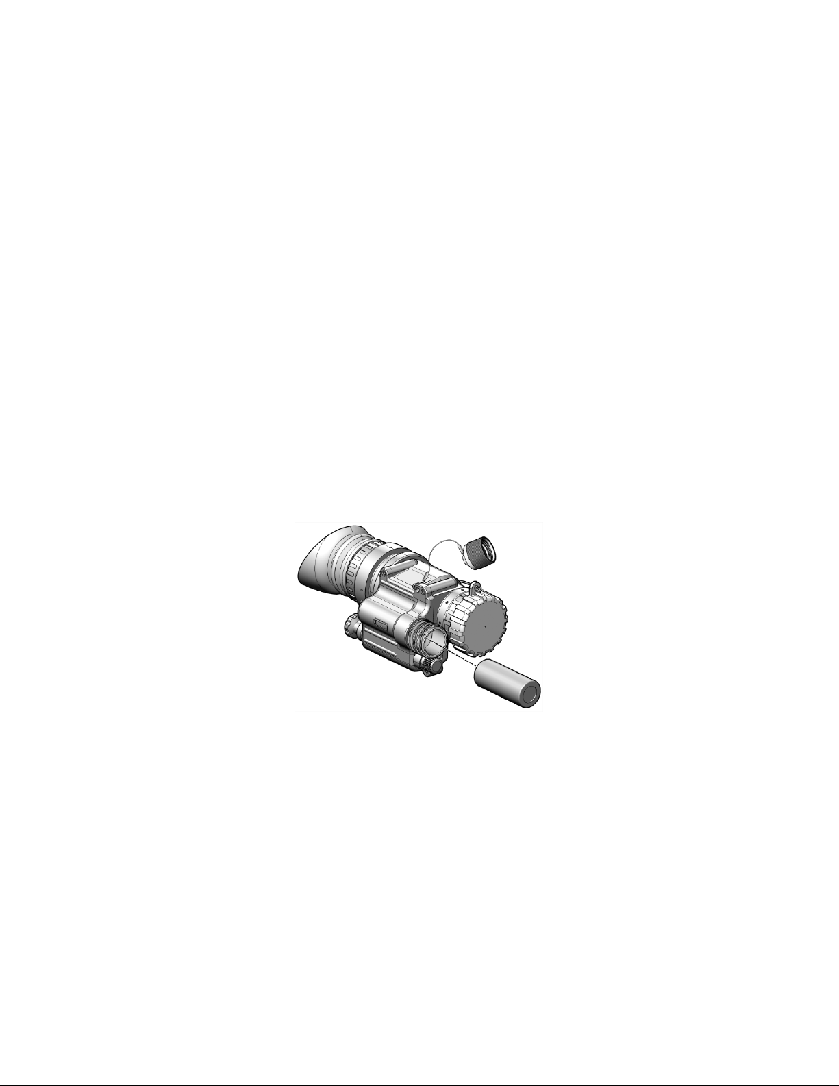
Access the battery compartment by turning the battery cap
counterclockwise. Install one AA lithium batt ery with the
positive terminal facing in as shown in Figure 2-1. Proper
battery orientation is clearly marked on the MNVD housing.
Replace the battery cap and turn clockwise to tighten.
2-2
Figure 2-1 Battery Installation
Page 23
2.2 BATTERY HANDLING – Continued
LOW BATTERY
CAUTION
Do not ship or store the MNVD with battery
installed.
Low Battery Indicator
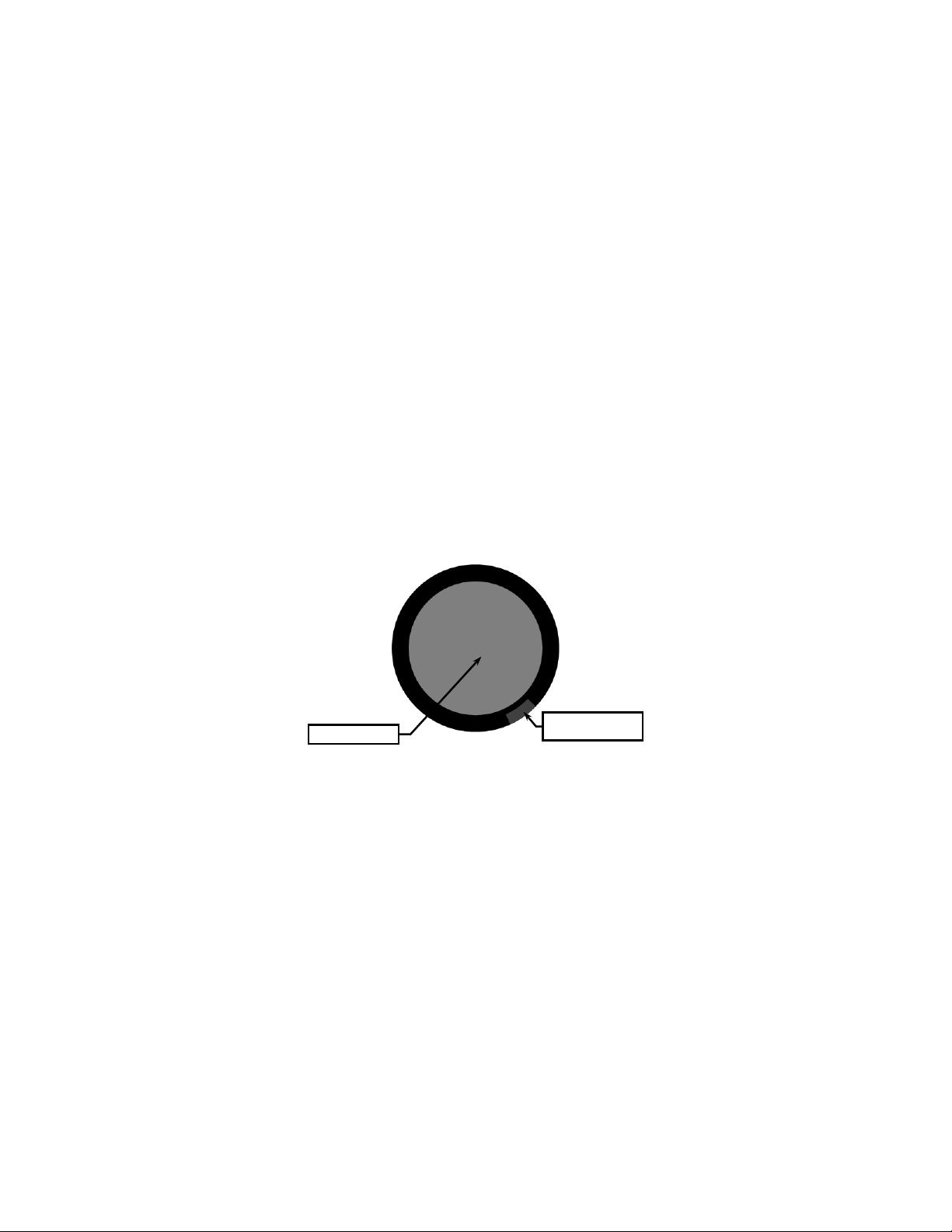
A red light visible through the eyepiece, just outside the
intensified field of view, indicates a low battery condition. It
will illuminate when approximately 30 minutes of operation
remain.
FIELD OF VIEW
INDICATOR
Figure 2-2 Low Battery Indicator
2.3 HEADMOUNT ASSEMBLY
The MNVD system comes with a headmount assembly that
may be worn on the head to permit hands-free operation of
the MNVD.
2-3
Page 24
2.3 HEADMOUNT ASSEMBLY – Continued
STRAP (2)
REAR CHIN
STRAP (2)
VERTICAL
Donning the Headmount Assembly
The following procedures for donning the headmount
assembly should be performed before attaching the
headmount adapter and MNVD.
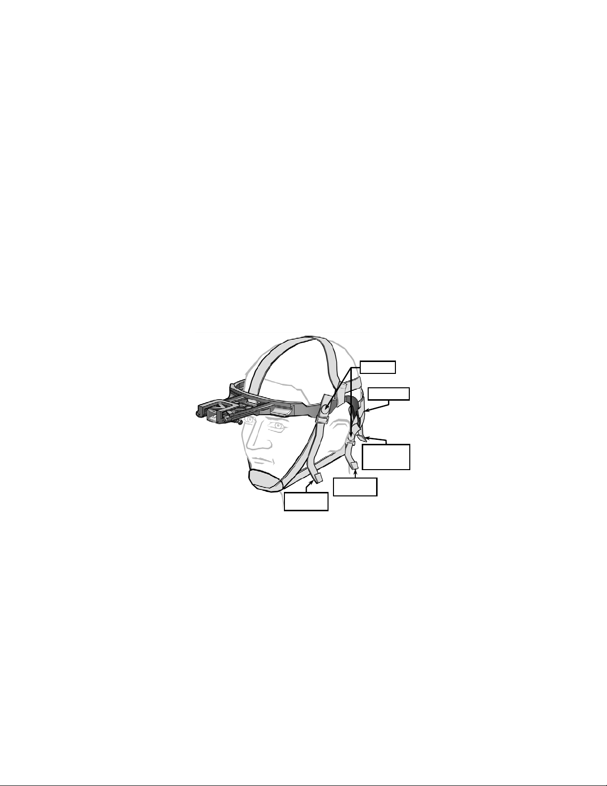
1. Review Figure 2–3 to gain familiarity with the labeled
items that will be referred to in this section.
SNAPS (4)
NECK PAD
ADJUSTMENT
STRAP
FRONT CHIN
Figure 2-3 Headmount Assembly
2-4
Page 25

2.3 HEADMOUNT ASSEMBLY – Continued
2. Loosen the four chin straps until the ends of each strap
are approximately two inches from the sliding bar
buckles.
3. Ensure the front and rear snaps are engaged.
4. Position the neck pad on the back of the neck and pull the
headmount assembly over the head.
5. Remove slack from the two rear chin straps but do not
tighten.
6. Adjust front and rear chin straps and vertical adjustment
strap until the headmount assembly is in a comfortable
but firm position.
NOTE
Minor strap adjustments may be necessary after
installing the headmount adapter and MNVD.
Headmount Adapter
The headmount adapter allows the MNVD to be install ed on
the headmount assembly or a suitably configured helmet.
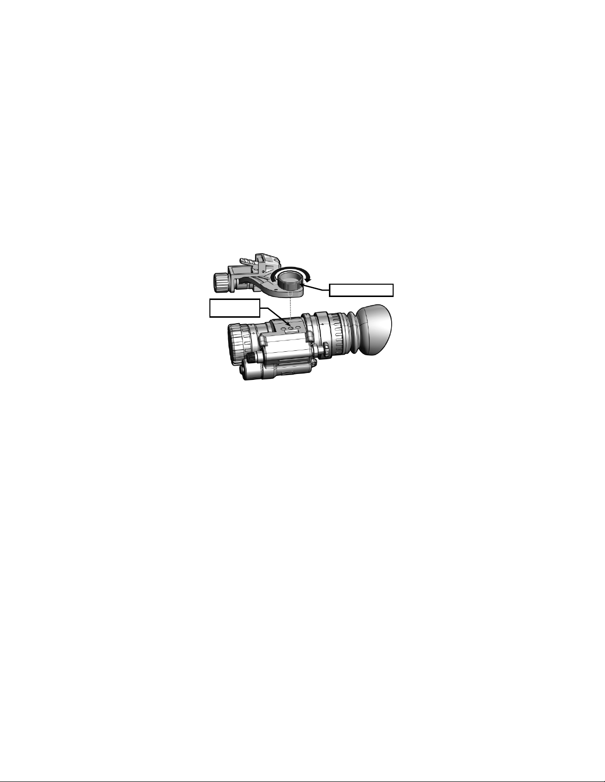
1. With the MNVD in one hand, use the free hand to orient
the headmount adapter above the mounting interface as
shown in Figure 2-4. Keying features in the headmount
adapter and mounting interface allow only one
orientation.
2. Rotate the thumbscrew clockwise to secure the
headmount adapter to the MNVD, taking care not the
cross threads.
2-5
Page 26
2.3 HEADMOUNT ASSEMBLY – Continued
THUMBSCREW
MOUNTING
INTERFACE
Figure 2-4 Headmount Adapter Installation
3. The headmount adapter is now installed on the MNVD.
Mounting
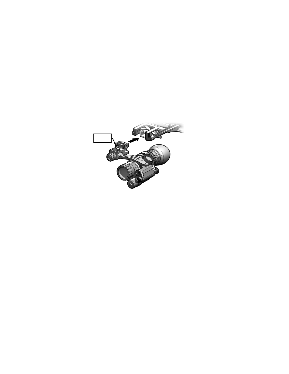
Align the headmount adapter with the receptacle on the
headmount assembly as shown in Figure 2-5 and push the
parts together until the mating features engage. To
disengage, press the release lever shown below.
2-6
Page 27
2.3 HEADMOUNT ASSEMBLY – Continued
LEVER
RELEASE
Figure 2-5 Mounting to Headmount Assembly
Positioning Adjustments
With the MNVD system installed, positioning adjustments
must be made for maximum performance and comfort.
Figures 2-6 and 2-7 show controls used for positioning
adjustments.
NOTE
Positioning adjustments are made with the MNVD
attached to the headm ount, the eyecup installed,
and the headmount properly donned. The MNVD
cannot be properly adjusted until the headmount
itself is correctly fitted.
2-7
Page 28
2.3 HEADMOUNT ASSEMBLY – Continued
NOTE
Optimal system performance and comfort of the
operator rely on c arefully following the procedures
below. The best visual performance is possible
only when the optical axis of the devic e is aligned
with the visual axis of the eye.
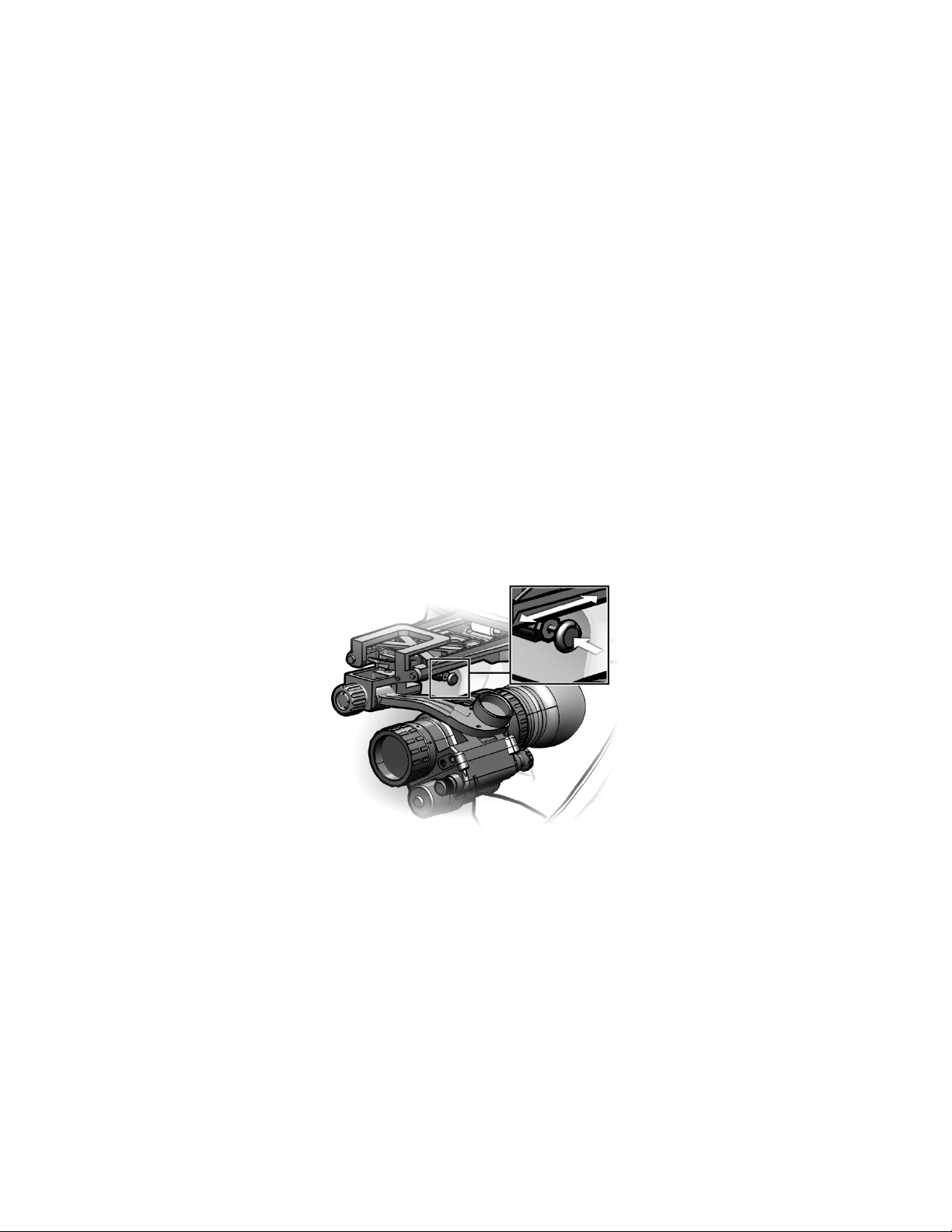
• Fore / Aft Adjustment. The MNVD can be moved
forward or backward relative to the head. Press the
fore / aft release button and slide the MNVD forward
or backward to achieve optimal eye relief.
2-8
Figure 2-6 Fore / Aft Release Button
Page 29
2.3 HEADMOUNT ASSEMBLY – Continued
• Height Adjustment. The headmount’s verti c al
adjustment strap (see Figure 2-3) provides for height
adjustment of the MNVD. Tighten or loosen the
vertical adjustment strap until the MNVD is level with
the operator’s eyes.
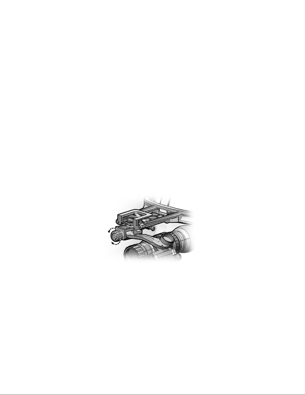
• Pupillary Adjustment. The MNVD can be moved in
an arc to provide best alignment with the operator’s
eye. Unscrew the adjustment knob to its full and
open position (see Figure 2-7). Gently push the
MNVD away from the operator’s head and rotate
clockwise or counterclockwise until proper
positioning is achieved. Screw in the adjustment
knob to lock the MNVD in place.
Figure 2-7 Adjustment Knob
2-9
Page 30

2.3 HEADMOUNT ASSEMBLY – Continued
The first row in Table 2-1 shows the optimal field of view for
the MNVD when positioning adjustments are correctly
performed. The remaining rows show unsatisfactory fields of
view when positioning adjustments are performed
incorrectly, along with corrective action that can be taken to
resolve the problem.
Table 2-1 Field of View and Positioning Adjustments
Field of View Remarks / Corrective Action
Optimal alignment.
Eye relief too long. Correct fore and aft
adjustment.
Eye relief too short. Correct fore and aft
adjustment.
Eyepiece set too left. Correct pupillary
adjustment.
Eyepiece set too right. Correct pupillary
adjustment.
2-10
Page 31
2.3 HEADMOUNT ASSEMBLY – Continued
THUMBSCREW
Table 2-1 Field of View and Positioning Adjustments –
Field of View Remarks / Corrective Action
MNVD field of view
Eyepiece field of view
Obstructed MNVD field of view
Continued
Positioned too high. Correct height
adjustment.
Positioned too low. Correct height
adjustment.
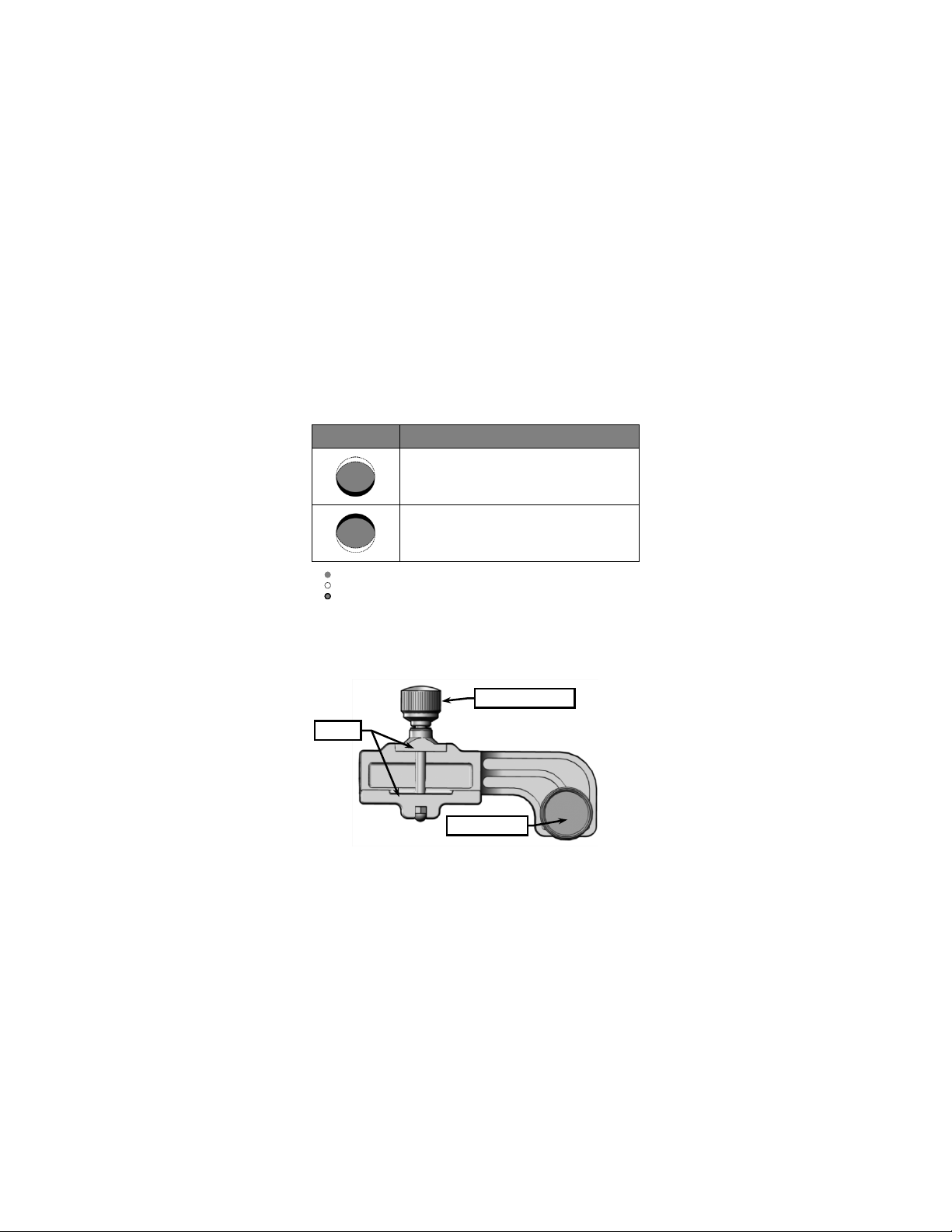
2.4 WEAPON MOUNTING INSTRUCTIONS
The weapon mount assembly allows the MNVD to be
mounted to weapons equipped with a MIL-STD-1913 rail.
MOUNTING SCREW
JAWS
Figure 2-8 Weapon Mount Assembly
2-11
Page 32
2.4 WEAPON MOUNTING INSTRUCTIONS – Continued
MOUNTING
INTERFACE
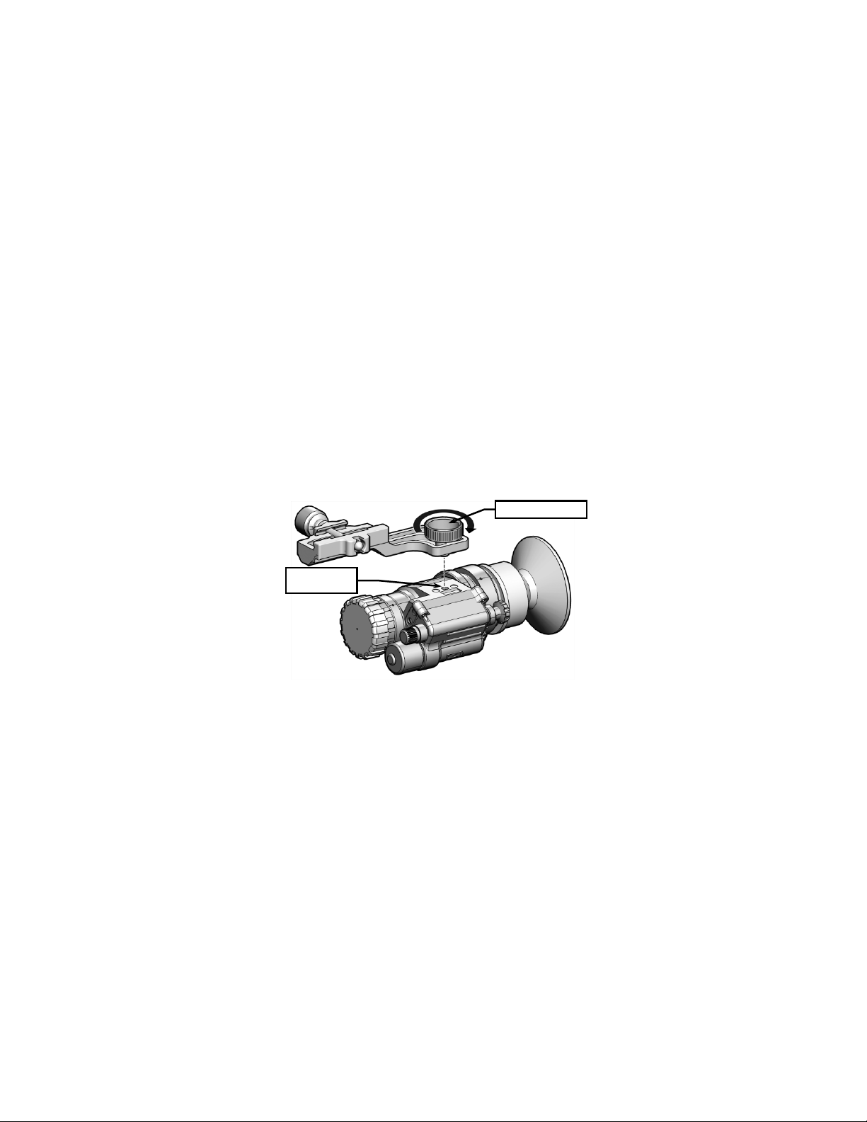
Installing the Weapon Mount Assembly
1. With the MNVD in one hand, use the free hand to orient
the weapon mount assembly above the mounting
interface as shown in Figure 2-9. Keying features in the
weapon mount assembly and mounting interface allow
only one orientation.
2. Rotate the thumbscrew clockwise to secure the weapon
mount assembly to the MNVD, taking care not the cross
threads.
THUMBSCREW
Figure 2-9 Weapon Mount Assembly Installation
3. The weapon mount assembly is no w i nstalled on the
MNVD.
2-12
Page 33
2.4 WEAPON MOUNTING INSTRUCTIONS – Continued
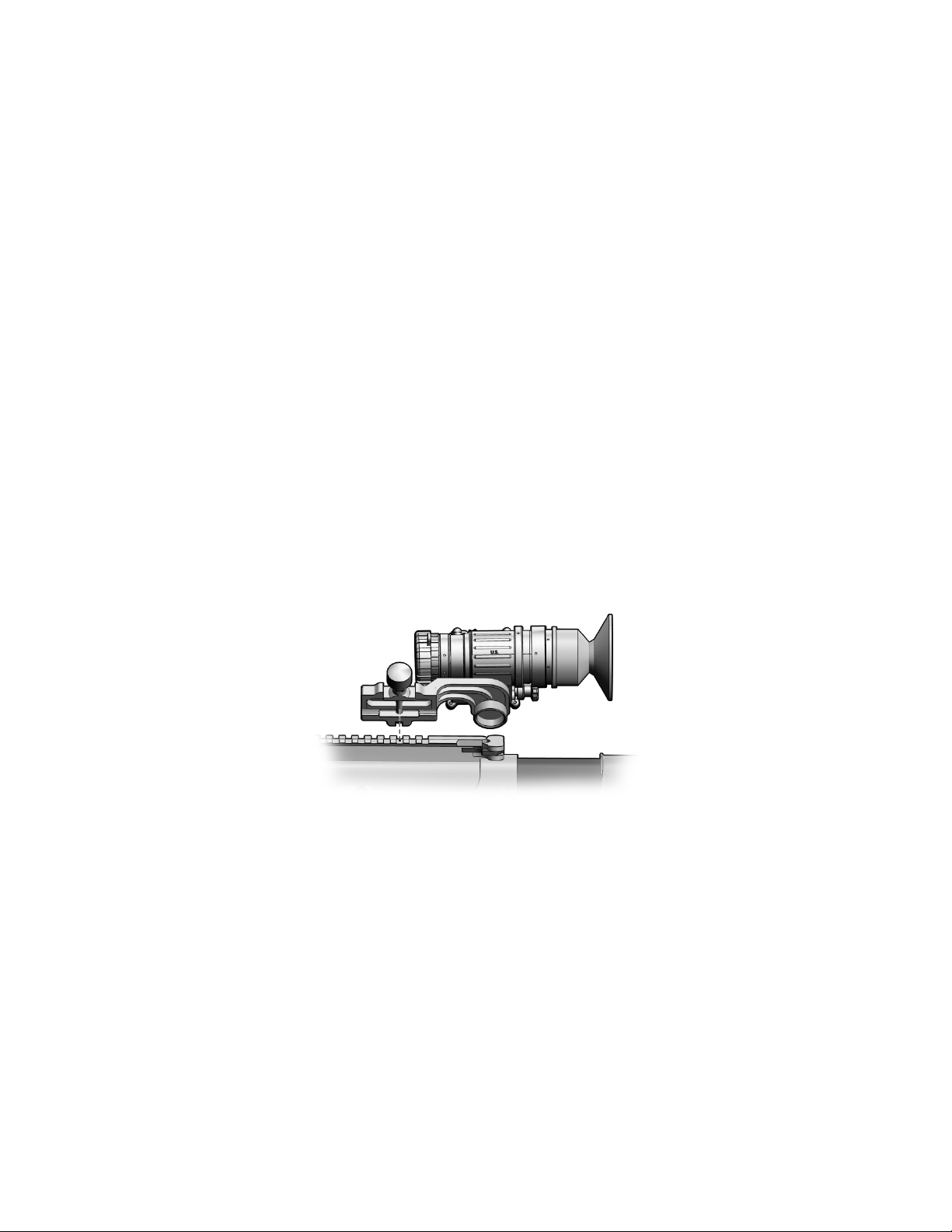
Mounting the MNVD
WARNING
Be sure the weapon is CLEAR and SAFE before
proceeding.
1. Loosen the mounting screw on the weapon mount
assembly until the jaws have sufficient space to fit over
the weapon rail.
2. Position the MNVD facing forward, ensuring the recoil lug
is seated in the desired recoil groove of the rail. While
pushing down and forward on the MNVD, turn the
mounting screw clockwise until snug.
Figure 2-10 Mounting the MNVD
2-13
Page 34

2.5 LENS ACCESSORIES
Objective Lens Cover
The objective lens cover affords additional protection to the
objective lens and protects the MNVD’s internal imaging
components. It should be pressed into place (installed) over
the objective lens whenever the MNVD is not being used. It
should also be installed when the MNVD is being used in
brightly lit environments. A small hole in the center of the
lens cover allows enough light to enter the MNVD when
operating in these conditions. In darker environments, better
performance will be observed with the lens cover uninstalled.
The objective lens cover is held captive to the MNVD by the
neck cord.
Sacrificial Win do w
A sacrificial window is provided to protect the objective lens
from becoming scratched or otherwise damaged. The
sacrificial window should be pressed into place (installed)
over the objective lens whenever the lens cover is not
installed.
Demist Shield
CAUTION
The coating on the demist shiel d may be damaged
if cleaned while wet. Clean the demist s hield only
when dry and using dry lens tissue.
2-14
Page 35
2.4 LENS ACCESSORIES – Continued
The demist shield is provided to protect the eyepiece from
becoming scratched or otherwise damaged, and to prevent
fogging of the eyepiece. It should be installed whenever the
MNVD is in use. With the eyecup removed, plac e the demist
shield over the eyepiece with the narrow side in. Taking
care not to smudge the eyepiece or demist shield, press the
demist shield into place.
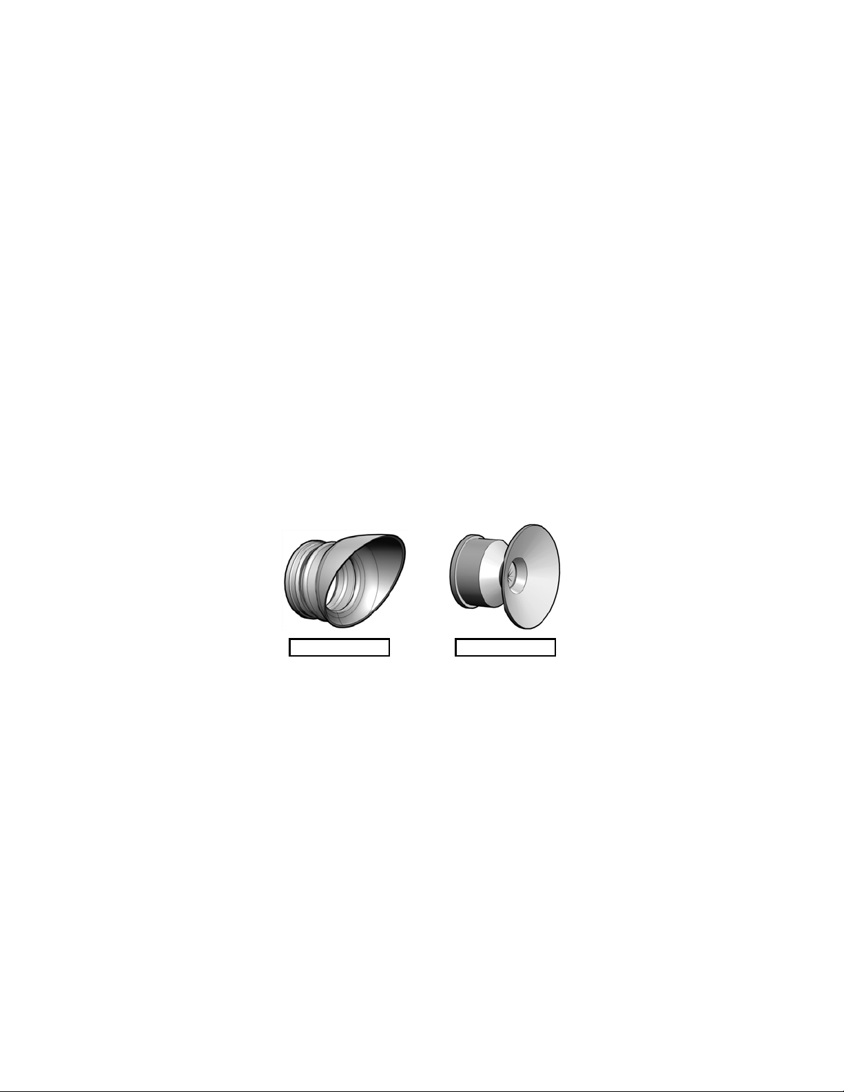
Eyecups
The MNVD is equipped with both a standard and shuttered
eyecup to accommodate a variety of tactical situations and
mounting configurations.
STANDARD EYECUP SHUTTERED EYECUP
Figure 2-11 MNVD Eyecups
To install, press the desired eyecup over the end of the
eyepiece. If installing the standard eyecup, rotate to obtain
proper eye / cheek weld.
2-15
Page 36

OPERATING INSTRUCTIONS
SECTION II
2.6 MODES OF OPERATION
The MNVD is powered on by turning the Mode Switch to the
desired position.
CAUTION
Pointing the MNVD at the sun without the lens
cover installed may damage internal imaging
components.
NOTE
The MNVD is equipped with a high light sensor
(see Figure 1-3) that detects ambient light
conditions and automatically shuts down the I
2
tube if conditions are so bright as to risk damagi ng
internal components. To reset (power on) the
MNVD after a high li ght shutdown, turn the Mode
Switch to the RESET / OFF position and then back
to the desired setting.
2-16
Page 37

2.6 MODES OF OPERATION – Continued
Mode Switch
Position
RESET
Turns MNVD off. Resets the MNVD after a high
available, ambient light.
Activates the MNVD using the IR LED Illuminator
Table 2-2 Mode Switch Operation
Effect
OFF
ON
IR
PULL
light shutdown.
Activates the MNVD using (and amplifying)
to provide an integrated light sourc e in condi tio ns
of extreme darkness.
2.7 IR LED ILLUMINATOR
WARNING
The IR LED Il lum inat or is detec tabl e by an enemy
using night vision devices. Detect ion is easier in
smoky, foggy, or rainy conditions. To reduc e the
risk of detection by an enemy using night vision
devices, avoid prolonged activation of the IR LED
Illuminator.
The IR LED Illuminator is used to provide a supplementary
light source in conditions of extreme darkness. In addition to
the IR mode described in Table 2-2, the IR LED Illuminator
may also be activated in a momentary setting. To
momentarily activate the IR LED Illuminator, turn the Mode
Switch to the ON position. Continue turning past the ON
position and hold. The IR LED Illuminator will remain
activated until the Mode Switch is released.
A red light in the eyepiece, just outside the intensified field of
view, indicates that the IR LED Illuminator is activat ed.
2-17
Page 38

2.7 IR LED ILLUMINATOR – Continued
INDICATOR
IR LED ILLUMINATOR
FIELD OF VIEW
Figure 2-12 IR LED Illuminator Indicator
2.8 GAIN (CONTRAST)
The MNVD is equipped with a gain control knob used to
adjust the gain (contrast) of the viewed image. When
looking through the eyepiece, turning the gain control knob
clockwise will provide more contrast. Turning the gain
control knob counterclockwise will provide less contrast.
2.9 FOCUS
The objective lens must be focused for the viewing distance
being observed. While looking at an object at least 9.8
inches (25cm) from the MNVD, rotate the objective focus
ring for best image clarity. A change in viewing distance
requires that the objective lens be refocused. If already
focused for a distance of at least 250 feet (76m), no change
in focus is required between this distance and infinity.
2-18
Page 39

2.10 DIOPTER ADJUSTMENT
The eyepiece may be focused to accommodate differences
in the visual acuity of individual operators, from +2 to -6
diopters. While looking at an object at least 9.8 inches
(25cm) from the MNVD, rotate the diopter adjuster to
achieve the sharpest possible image.
2.11 STARTUP PROCEDURES
To achieve optimal performance and image clarity, the
following procedures should be accomplished in the order
presented, each time the MNVD is placed into use.
1. Perform mounting procedures and positioning
adjustments as applicable:
a. For head or helmet-mounted configurations, don the
headmount and MNVD and make all positioning
adjustments per section 2.3.
b. For weapon-mounted configurations, install the
weapon mount assembly and mount to the host
weapon per section 2.4.
2. Turn the Mode Switch to the desired position per section
2.6.
3. Adjust the gain (contrast) to a comfortable viewing level
per section 2.8.
4. Rotate the objective focus ring for best image clarity.
5. Make diopter adjustments per section 2.10.
2-19
Page 40

Page 41

CHAPTER 3
Malfunction
Probable Cau s e
Corrective Action
1. No image is
a. Batteries are improperly
a. Verify batter i es ar e properly
Installation.
b. Battery power is low.
b. Replace batter i es per section
2.2, Battery Installation.
c. Battery contacts require
c. Clean batt er y co nt ac t s per
2. Image abruptly
a. High light shutdown has
a. Reset (power on) the MNVD
necessary.
3. Poor or
a. Lens cover installed
a. Remove lens cover per section
b. Lens cover not installed
(bright ambient conditions).
b. Install lens cover per section
2.5, Objective Lens Cover.
MAINTENANCE
OPERATOR MAINTENANCE
3.1 TROUBLESHOOTING PROCEDURES
The procedures below will help correct some of the basic
problems that may arise with the MNVD. If the equipment
malfunction is not listed, or the actions listed do not correct
the fault, refer to section 3.4 for additional guidance.
Table 3-1 Troubleshooting Procedures
SECTION I
present when
turning on the
MNVD.
turns off when in
ON or IR modes.
degraded image.
installed.
cleaning.
been initiated.
(dark ambient conditions).
installed per section 2.2, Battery
section 3.2, Battery Compartment
and Battery Cap.
per section 2.6. Install the
objective lens cover per section
2.5, Objective Lens Cover, if
2.4, Objective Lens Cover.
3-1
Page 42

3.1 TROUBLESHOOTING – Continued
Malfunction
Probable Cau s e
Corrective Action
3. Poor or
c. Insufficient ambient
c. Turn the Mode Switch to the IR
d. Gain (contrast) not
setting.
d. Adjust gain (contrast) to a
e. Not focused for viewing
e. Focus objecti v e lens per
f. Diopter setting not
adjusted correctly.
f. Adjust diopter setting per
section 2.10.
g. Sacrificial window
grime.
g. Clean sacrificial window and/or
h. Sacrificial window
h. Replace sacrificial window
i. Objective lens and/or
i. Remove sacrificial window
section 3.2, Optical Surfaces.
4. IR LED
insufficient light.
a. IR LED Illuminator exit
a. Clean IR LED Ill um i nator exit
b. Viewed scene is outside
Illuminator.
b. Limit use of IR LED Illuminator
meters of the MNVD.
Table 3-1 Troubleshooting Procedures – Continued
degraded image –
Continued.
Illuminator do es
not appear to
operate or
provides
3-2
light.
adjusted to an ap pr o pr i ate
distance being observed
(minimum 9.8 inches).
and/or demist shield
obscured by di rt , dus t, or
and/or demist shield
cracked or scratched.
eyepiece obscured by dirt,
dust or grime.
port is dirty.
effective ra ng e of I R LED
position to provide IR light source
per section 2.6, or momentarily
activate the IR LED Illum i nator per
section 2.7.
comfortable level per section 2.8.
section 2.9.
demist shield per section 3.2,
Optical Surfaces.
and/or demist shield per section
2.5.
and/or demist shield. Clean
objective lens and/or eyepiece per
port per section 3.2, Optical
Surfaces.
to viewed scenes within a few
Page 43

3.2 INSPECTION / CLEANING
The operator should inspect the MNVD before each use and
after it has been in extreme conditions, such as prolonged
exposure to intense temperatures. The following procedures
will extend the life of the MNVD and help ensure safe
operation.
WARNING
Remove the MNVD from the weapon before
inspecting, cleaning, or performing other
maintenance functions.
WARNING
Prior to performing any inspection or maintenance
procedure, verify that batteries are not installed.
MNVD Housing
To clean the MNVD housing, rinse with water or mild soap
and water and then wipe dry with a soft cloth. Clean around
adjusters, levers, and interfaces with a cotton swab.
Battery Compartment
Inspect the battery compartment for dirt, dust, or corrosion.
Dirt or debris that cannot be shaken loose from the battery
compartment may be removed using a clean cloth or cotton
swab. Periodically lubricate the o-ring with fluorinated
grease. The o-ring should be replaced if it becomes cut,
nicked, or dried out per section 3.3, Replacing Battery
Compartment O-Ring. If necessary, clean battery contacts
with a cotton swab and isopropyl alcohol.
3-3
Page 44

3.2 INSPECTION / CLEANING - Continued
Battery Cap
Inspect the battery cap for dirt, sand, and grime. Thoroughly
clean the battery cap and o-ring by flushing with water and
wiping with a cotton swab. Periodically lubricate the o-ring
with fluorinated grease. If necessary, clean the battery
contact with a cotton swab and isopropyl alcohol.
Optical Surfaces
CAUTION
The coating on the demist shiel d m ay be damaged
if cleaned while wet. Clean the demist shield only
when dry and using dry lens tissue.
Inspect optical surfaces for dirt, dust, and grime. Except for
the demist shield, clean with water or mild soap and water.
Fine cleaning of the optical surfaces should be performed
using the provided lens tissue and lens cleaning solution, or
the flexible tip of the lens pen. Avoid using excessive force
as this may scratch the lenses. The sacrificial window and
demist shield should be replaced if scratches degrade
performance or cracks are present.
Neck Cord
Inspect the neck cord for any signs of cuts, nicks, or fraying.
Replace as necessary per section 3.3, Lens Cover / Neck
Cord Replacement.
3-4
Page 45

3.3 CORRECTIVE MAINTENANCE PROCEDURES
The MNVD
has no internal parts or assemblies replaceable
by the user or organizational level personnel. Refer to
section 3.4 regarding maintenance and/or repair actions
beyond those described in this manual.
Replacing Battery Compartment O-Ring
No tools are required to perform this procedure.
1. Access the battery compartment by turning the battery
cap counterclockwise.
2. Use the fingers of one hand to squeeze the battery
compartment o-ring while simultaneously pushing it out of
its retaining groove. Grasp the o-ring with fingers of the
other hand and pull it off the battery compartment.
3. Ensure the o-ring retaining groove is clean and free of
debris.
4. Stretch the replacement o-ring over the battery
compartment and into its retaining groove.
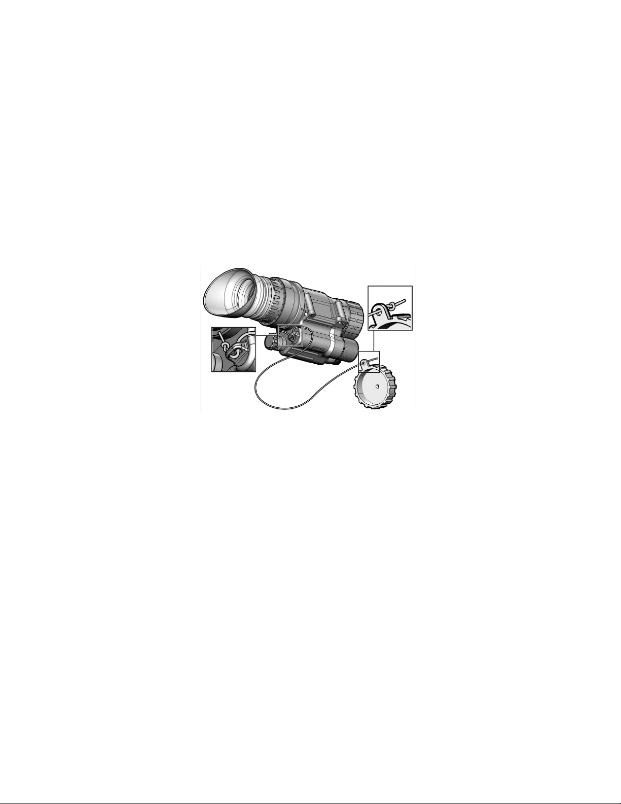
Neck Cord Replacement
No tools are required to perform this procedure.
1. Feed one end of the neck cord through the channel on
the MNVD housing as shown in Figure 3-1.
2. Feed the other end of the neck cord through the tab in the
lens cover.
3. Secure both ends with a knot.
4. Place the lens cover over the objective lens.
3-5
Page 46
3.3 CORRECTIVE MAINTENANCE PROCEDURES –
Continued
3-6
Figure 3-1 Neck Cord Replacement
Page 47

SERVICE / PACKING AND UNPACKING
SECTION II
3.4 SERVICE / REPAIR
For service, repair, or replacement, first e-mail
or call toll-free 1-877-744-4803.
To assist with determining if the item is repairable, the
following information will be requested:
a. Serial number of the defective item;
b. Thorough description of the malfunction, defect, or
damage; and
c. If known, an explanation as to how the malfunction,
defect or damage occurred.
If the item is determined to be beyond economical repair,
follow applicable replacement procedures through your
Property Officer. If it is determined that the item is under
warranty, or should be returned for repair, a Return Material
Authorization (RMA) number will be provided.
When returning the MNVD for service / repair, the following
procedures should be followed to prevent any additional
damage:
1. Be sure that the MNVD is free of all contaminants such as
dirt or any other foreign material.
2. Remove battery.
3. Place the MNVD in the soft carrying case.
3-7
Page 48

3.4 RETURN INSTRUCTIONS – Continued
Place the item and a copy of the test report or detailed
description of the failure in a suitable packing container.
Mark the package with “Field Return” and the RMA number.
Ship via fastest, traceable, pre-paid means to:
L-3 Communications Corporation
Warrior Systems Division
Insight Operations
9 Akira Way
Londonderry, NH 03053
3.5 WARRANTY INFORMATION
The MNVD is under warranty from defects in material and
workmanship for a minimum of one (1) year from the date of
manufacture. This warranty does not protect against
damage due to misuse, mishandling or battery leakage.
Additional warranty coverage may have been provided
through the contract or via subsequent contract extension.
Specific warranty terms can be obtained from your
procurement agent, Contracting Officer or L-3 Warrior
Systems, Insi g h t.
3.6 NON-WARRANTY INF ORMATION
Non-warranty repairs are subject to an evaluation fee. The
item will be tested and evaluated for failure, then customer
permission and payment terms are obtained prior to any
repairs being performed.
3-8
Page 49
APPENDIX A
1
3
7
14
REPAIR PARTS LIST
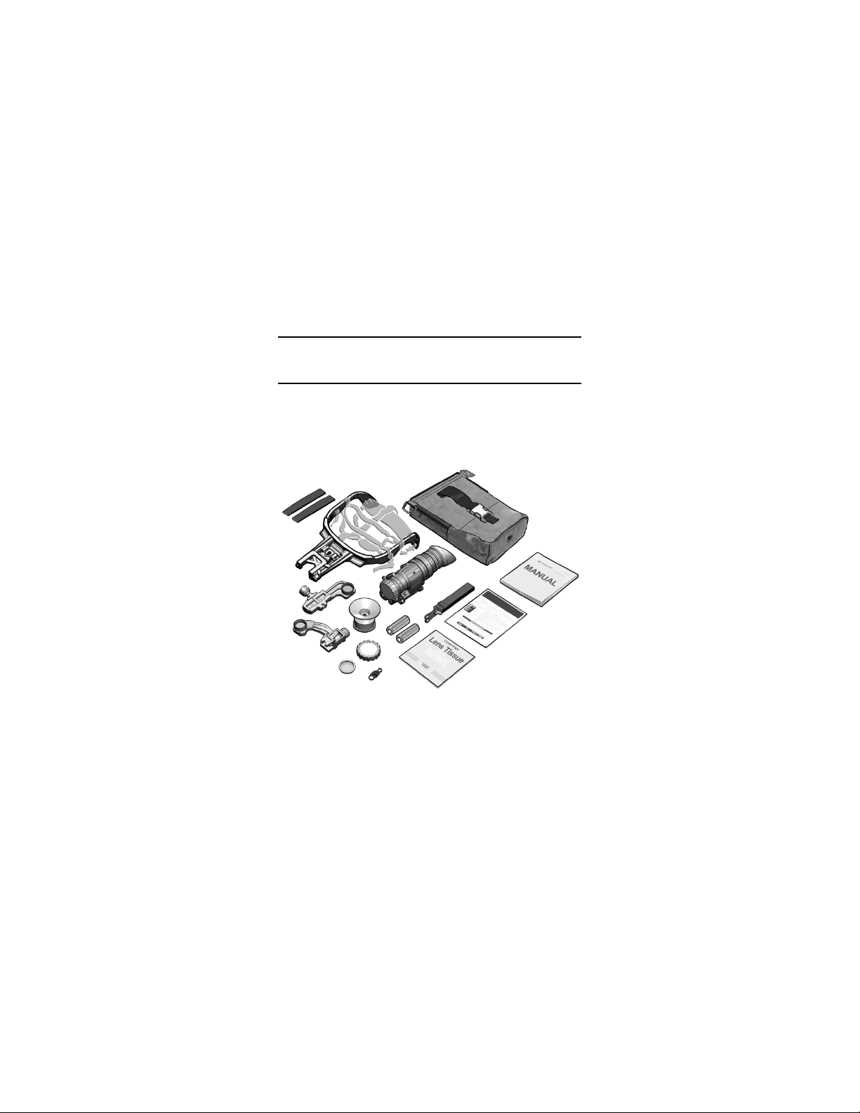
SCOPE
This Appendix lists end item components and repair parts for
the MNVD.
4
2
12
11
13
10
15
9
8
16
6
5
Figure A-1 End Item Compone nt s
A-1
Page 50

SCOPE – Continued
ITEM
NATIONAL
PART
1
8415-01-560-1800
7B435
Browpad, Medium
1
2
8415-01-560-1799
7B436
Browpad, Thick
1
3
TBD
7B268
Headmount Assembly
1
4
TBD
7B262
Soft Carrying Case
1
5
N/A
MNVD-TM-ITI
Operator Manual
1
6
N/A
MNVD-QRG-ITI
Quick Reference Guide
1
7
6760-01-556-4306
7B626
Lens Tissue
1
8
TBD
MND-187
Retaining Cord
1 9 TBD
7B264
Sacrificial Window
1
10
5855-01-444-1230
MND-200
Demist Shield
1
11
TBD
MND-160
Adapter, Headmount / Helmet Mount
1
12
TBD
MND-140
Mount Assembly, Weapon
1
13
6650-01-444-1229
A3256345
Eyecup, Shuttered
1
MNVD Assembly
15
6135-01-559-9637
M30-044
Battery, 1.5V, AA Lithium
2
16
8465-01-559-8427
7B267
Shoulder Strap Assembly
1
Browpad, Thin
(pre-installed on Headmount Assembly)
Table A-1 List of End Item Components
NO.
STOCK NUMBER
NUMBER
DESCRIPTION QTY
14 N/A 245000
- 8415-01-598-3125 7B280
A-2
(see Figure A-2 for parts breakdown)
1
1
 Loading...