

Page 1

MRD-TM-ITI
OPERATOR MANU AL
FOR THE
Miniature Red Dot Sight
(MRDS)
Rev. 3 2 March 2011
Page 2

Page 3

1. GENERAL SAFETY INSTRUCTIONS
This manual contains operating instructions and maintenance procedures which may cause
injury or death to personnel, or damage to equipment if not properly followed. Prior to
performing any task, the WARNINGs, CAUTIONs and NOTEs included in that task shall be
reviewed and understood.
2. WARNINGS, CAUTIONS AND NOTES
Safety headings used in this manual and their respective definitions are as follows:
SAFETY SUMMARY
WARNING..
Highlights an essential operating or maintenance procedure, practice, condition
or statement, which, if not strictly observed, could result in injury to, or death of,
personnel or long term health hazards.
Highlights an essential operating or maintenance procedure, practice, condition
or statement, which, if not strictly observed, could result in damage to, or
destruction of, equipment or loss of mission effectiveness.
Highlights an essential operating or maintenance procedure, condition or
statement.
CAUTION..
NOTE
i
Page 4

3. SAFETY PRECAUT IONS
The following general safety precautions supplement the specific WARNINGs, CAUTIONs and
NOTEs that appear elsewhere in this manual.
3.1 Weapons Safety . The Miniature Red Dot Sight (MRDS) is designed to be used with
destructive weapon systems. Improper operation or misuse of the MRDS with these weapon
systems could lead to personal injury or death of either the operator or other persons within
weapons range. Safe firearms handling procedures must be practiced at all times.
Use of acetone or gun cleaning agents containing perchloroethylene or
methylene chloride may permanently damage the MRDS.
3.2 Batteries . The MRDS is powered by one lithium CR1632 battery. The following safety
precautions apply when handling lithium batteries:
• Do not short circuit, puncture, incinerate, or disassemble.
• Do not attempt to recharge.
• Prior to use, inspect the battery for cracks, dents, leakage, or bulging. Never install
a defective battery in the MRDS.
CAUTION..
ii
Page 5

TABLE OF CONTENTS
SAFETY SUMMARY ............................................................................................................. I
TABLE OF CONTENTS ....................................................................................................... III
LIST OF FIGURES .............................................................................................................. IV
LIST OF TABLES ................................................................................................................ IV
CHAPTER 1 ............................................................................................................................ 1-1
INTRODUCTION ............................................................................................................... 1-1
SECTION I .............................................................................................................................. 1-1
GENERAL INFORMATION ............................................................................................ 1-1
SECTION II ............................................................................................................................. 1-4
EQUIPMENT DESCRIPTION .......................................................................................... 1-4
CHAPTER 2 ............................................................................................................................ 2-1
OPERATING INSTRUCTIONS .......................................................................................... 2-1
SECTION I .............................................................................................................................. 2-1
PREPARATION FOR USE AND INSTALLATION ......................................................... 2-1
SECTION II ........................................................................................................................... 2-11
OPERATING PROCEDURES ........................................................................................ 2-11
CHAPTER 3 ............................................................................................................................ 3-1
MAINTENANCE AND SERVICING ................................................................................... 3-1
SECTION I .............................................................................................................................. 3-1
MAINTENANCE INSTRUCTIONS ................................................................................. 3-1
SECTION II ............................................................................................................................. 3-3
SERVICE / PACKING AND UNPACKING ..................................................................... 3-3
APPENDIX A ......................................................................................................................... A-1
REPAIR PARTS / ACCESSORIES ................................................................................... A-1
iii
Page 6

LIST OF FIGURES
Figure 1-1 MRDS Mounted to ACOG® .................................................................................. 1-1
Figure 1-2 MRDS Major Components .................................................................................... 1-6
Figure 2-1 Battery Installation ................................................................................................ 2-2
Figure 2-2 Mounting Procedures ............................................................................................ 2-3
Figure 2-3 Boresight Adjusters ............................................................................................... 2-4
Figure 2-4 Strike Point Calculation ......................................................................................... 2-6
Figure 2-5 Designated Strike Zone ........................................................................................ 2-8
Figure 2-6 MRDS Features and Controls ............................................................................. 2-11
Figure 3-1 Red Dot Aperture .................................................................................................. 3-2
Table 1-1 Technical Specifications ........................................................................................ 1-5
Table 1-2 List of Major Components ...................................................................................... 1-7
Table 2-1 Red Dot Adjustments ............................................................................................. 2-5
Table 2-2 Modes of Operation ............................................................................................. 2-12
Table A-1 Repair Parts / Accessories ................................................................................... A-1
LIST OF TABLES
iv
Page 7
CHAPTER 1
INTRODUCTION
SECTION I
GENERAL INFORMATION
1.1 SCOPE
This manual is intended for use by operators of the Miniature Red Dot Sight (MRDS). It
provides a system description, operational procedures, and maintenance responsibilities.
Complete familiarization with this manual prior to using the equipment will ensure safe
operation and maximum effectiveness of the MRDS.
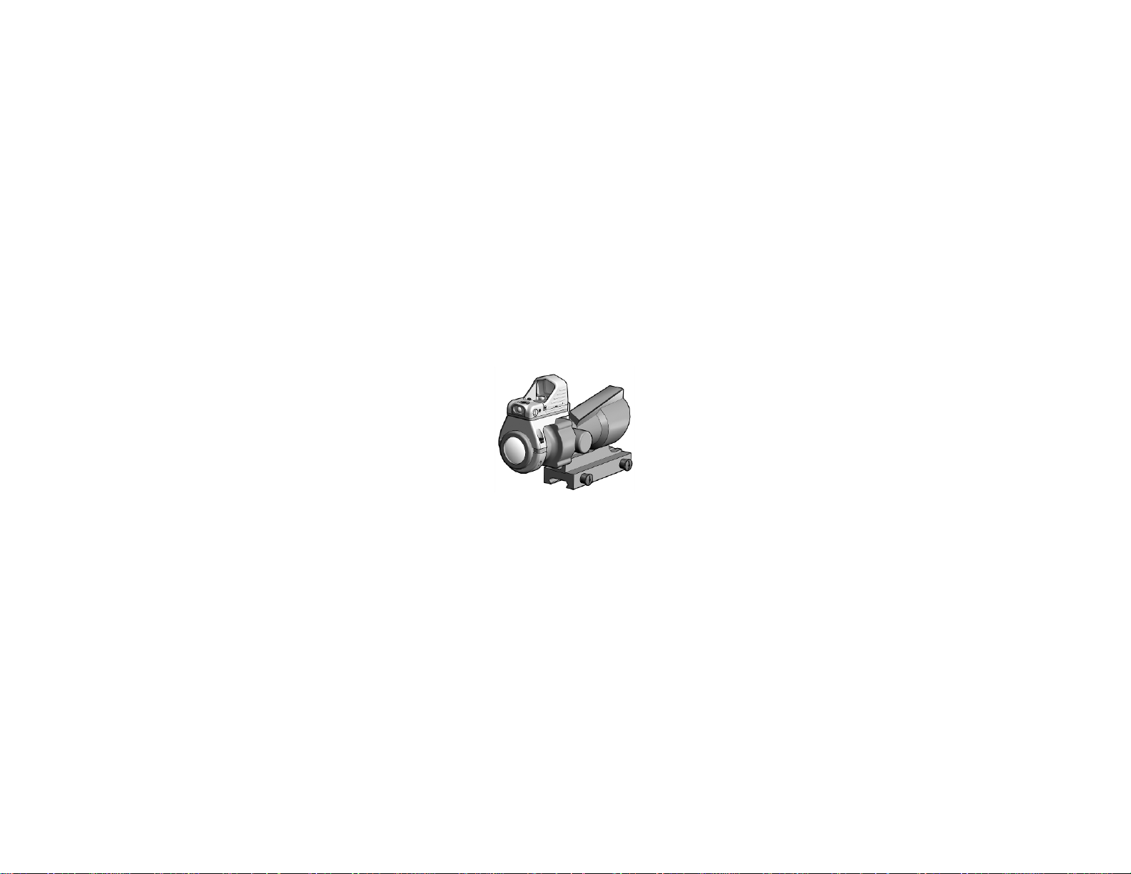
Figure 1-1 MRDS Mounted to ACOG®
1-1
Page 8

1.2 MODEL NUMBER AND EQUIPMENT NAME
This manual applies to the following MRDS models:
MRD-002-A1, Miniature Red Dot Sight (MRDS), Black Housing, 3.5 MOA Red Dot
MRD-002-A2, Miniature Red Dot Sight (MRDS), Tan Housing, 3.5 MOA Red Dot
MRD-002-A3, Miniature Red Dot Sight (MRDS), Black Housing, 7.0 MOA Red Dot
MRD-002-A4, Miniature Red Dot Sight (MRDS), Tan Housing, 7.0 MOA Red Dot
Because this manual applies to several different MRDS models, pictures contained herein may
not be representative of the exact model purchased or issued.
1.3 MANUFACTURER
L-3 Insight Technology Incorporated
9 Akira Way
Londonderry, NH 03053 USA
1.4 PURPOSE OF EQUIPMENT
The MRDS is a passive, red dot, reflex weapon sight designed for rapid target acquisition at
ranges of less than 150 meters.
1-2
Page 9

ACOG®
Advanced Combat Optical Gunsight
C
Celsius
F
Fahrenheit
m
Meter
mm
Millimeter
MOA
Minutes of Angle
mrad
Milliradians
MRDS
Miniature Red Dot Sight
NSN
National Stock Number
TBD
To Be Determined
V
Volt
1.5 ABBREVIATIONS AND ACRONYMS
Abbreviations and acronyms used in this manual are listed as follows:
RMA Return Material Authorization
1-3
Page 10

SECTION II
EQUIPMENT DESCRIPTION
1.6 SYSTEM DESCRIPTION
The MRDS is a passive, red dot, reflex weapon sight designed for rapid target acquisition at
ranges of less than 150 meters. It may be used as a stand-alone primary sight or as a
secondary sight when mounted on top of other optical sighting devices.
The MRDS utilizes a red aiming dot that can be automatically or manually adjusted in
brightness to accommodate changes in ambient lighting conditions.
The MRDS attaches directly to a DOCTER® sight mount, which in turn allows it to be hosted
on a wide variety of optical sighting devices and weapons.
The MRDS is a ruggedized device designed for operat ion in battlefield env ironm ents.
1-4
Page 11

Length
1.9 inches
Width
1.1 inches
Height
1.2 inches
Power Source
1 3V CR1632 battery
1 year continuous operation in
Field of View
12.5° horizontal at 4” eye relief
Magnification
1x
Operating Temperatures
-40°F (-40°C) to 120°F (49°C)
Storage Temperatures
-71°F (-57°C) to 160°F (71°C)
Immersion
66 feet for 2 hours
1.7 TECHNICAL SPECIFICATIONS
Table 1-1 provides technical specifications for the MRDS.
Weight
(with battery and DOCTER®
sight mount interface)
Table 1-1 Technical Specifications
WEIGHT AND DIMENSIONS
0.9 ounces
POWER AND PERFORMANCE
Battery Operating Life
photodiode mode
1-5
Page 12
1.8 MAJOR COMPONENTS
1
6 7 8
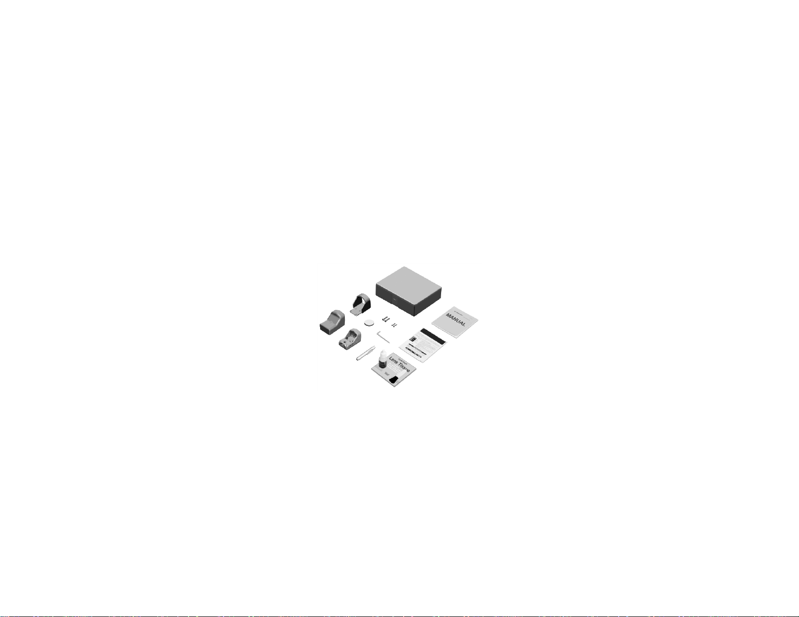
The MRDS is available in several variants with a wide array of accessory items. Figure 1-2
and shows components and parts for the entire family of MRDS configurations. Therefore,
some of the items shown may not be applicable to your specific configuration. Table 1-2
provides a brief functional description of each item. The “Key” column in Table 1-2
corresponds to the label numbers in Figure 1-2.
3
2
10
12
11
4
9
5
Figure 1-2 MRDS Major Components
1-6
Page 13

Key
Major Component
Function
1
Soft Cover
When placed over the MRDS, protects the sight
from sand and dust.
2
3
Shipping / Storage Case
Allows for shipping and/or storage of the MRDS
instructions specific to the MRDS.
5
MRDS.
6
Lens Cleaning Kit
A lens brush, lens tissue, and cleaning solution
7
Lens Pen
A compact, dry alternative to the Lens Cleaning Kit
used to clean the optical surfaces of the MRDS.
Protective Shield When mounted in conjunction with the MRDS,
Table 1-2 List of Major Components
provides additional protection against possible
damage.
and accessories.
4
Operator Manual Provides detailed operating and maintenance
Quick Reference Guide Provides at-a-glance operating procedures for the
used to clean the optical surfaces of the MRDS.
1-7
Page 14

Key
Major Component
Function
8
MRDS Assembly
A passive, red dot, reflex weapon sight designed
150 meters.
9
Battery, CR1632
One 3V lithium battery used to power the MRDS.
10
Mounting Screws,
Used to secure the MRDS with the Protective
11
Mounting Screws, 8mm
Used to secure the MRDS (without the Protective
Shield) to a DOCTER® sight mount.
12
Hex Head Wrench, M2
Used to tighten or loosen the mounting screws.
Table 1-2 List of Major Components (cont’d)
for rapid target acquisition at ranges of less than
10mm
Shield to a DOCTER® sight mount.
1-8
Page 15

CHAPTER 2
2.1 UNPACKING THE EQUIPMENT
Before unpacking the equipment, verify that all major components are present. If any of the
major components are missing, seek guidance from the equipment issuing authority.
2.2 INSPECTION OF THE EQUIPMENT
Before use, inspect all pieces of equipment for any damage such as cracks, loose parts, or
other visible defects. If any damage or defects are noted, seek guidance from the equipment
issuing authority.
2.3 BATTERY HANDLING
2.3.1 Battery Inspection . Before installation, inspect the battery for any cracks, dents,
leakage, or bulging. Never install a defective battery in the MRDS.
The captive screws on the hinged lid of the battery compartment need only be
tightened until snug in order to ensure proper seating of the o-rings. Using
excessive force may result in permanent damage to the MRDS.
OPERATING INSTRUCTIONS
PREPARATION FOR USE AND INSTALLATION
SECTION I
CAUTION..
2-1
Page 16
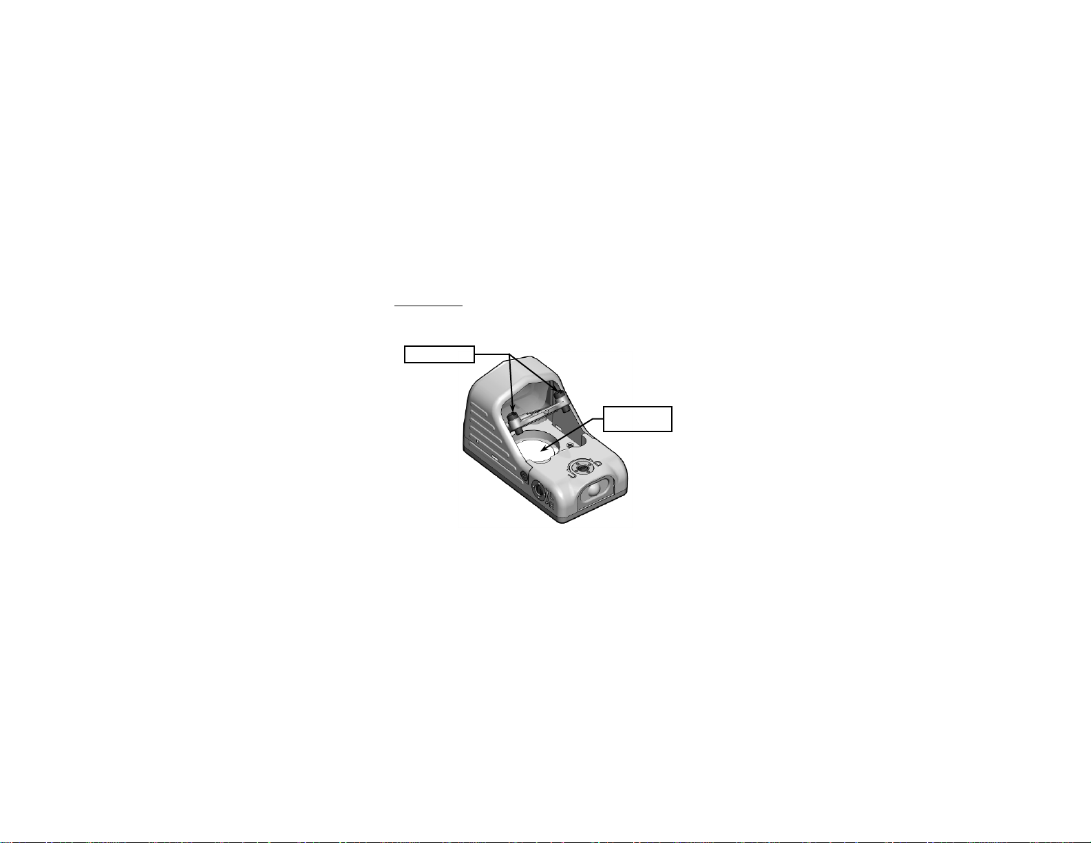
2.3.2 Battery Installation . With a small, slotted screwdriver, access the battery compartment
Battery
by loosening the two captive screws and lifting the hinged lid as shown in Figure 2-1. Install
one CR1632 lithium battery with positive side facing up. Proper battery orientation is marked
on the lid. Reseat the hinged lid and tighten the captive screws until snug.
Captive Screws
Compartment
Figure 2-1 Battery Installation
2-2
Page 17
2.4 MOUNTING PROCEDURES
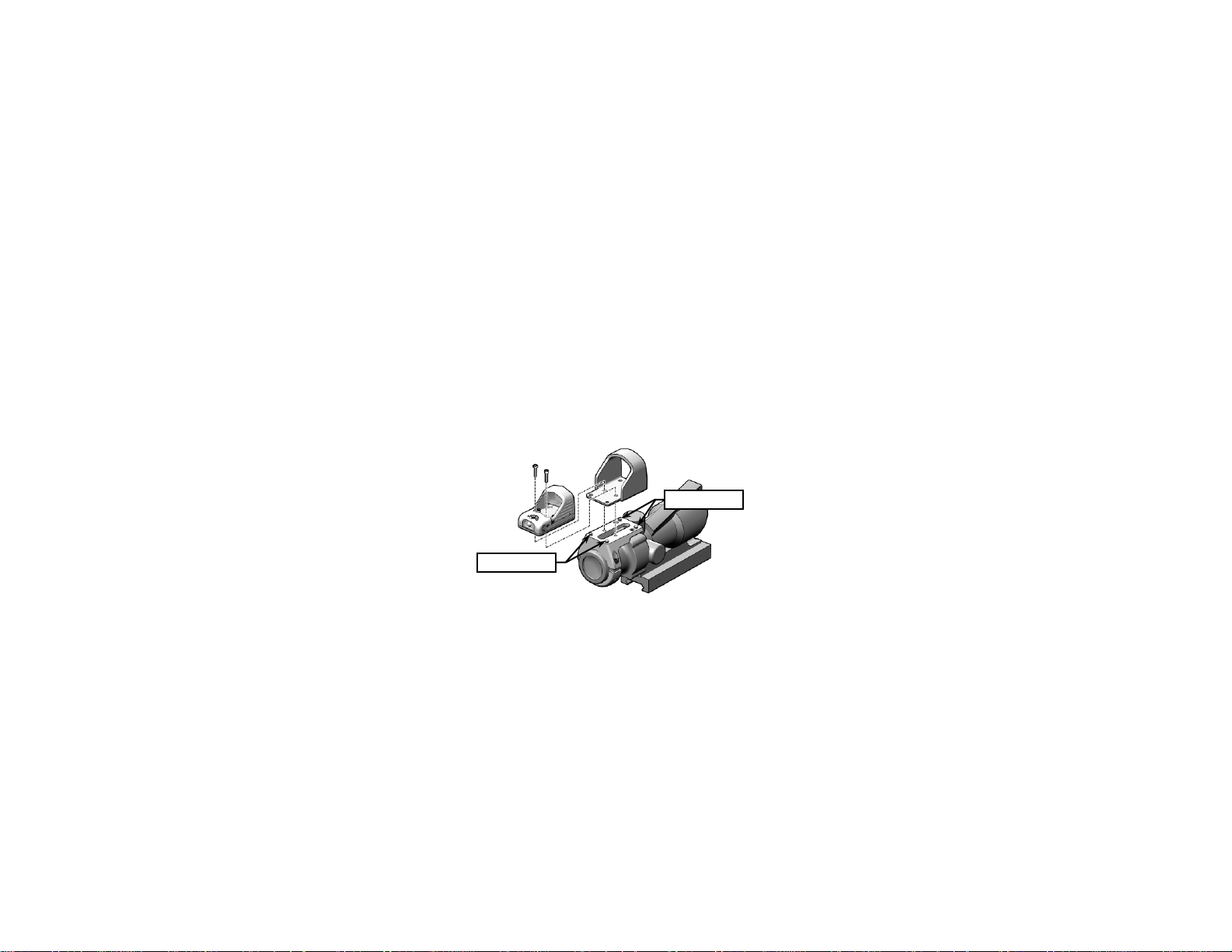
Two 8mm screws are used to secure the MRDS to a DOCTER® sight mount as shown in
Figure 2-2. Use the provided 10mm screws if also installing the Protective Shield.
a. Slide the MRDS in the Protective Shield (if being installed).
b. Place the MRDS (and Protective Shield) onto the mounting studs of the DOCTER®
sight mounting plate.
c. With an M2 hex head wrench, secure the MRDS to the DOCTER® sight mounting
plate by installing and then tightening the appropriate mounting screws.
Mounting Studs
Mounting Studs
Figure 2-2 Mounting Proced ur es
2-3
Page 18
2.5 BORESIGHTING / ZEROING PROCEDURES
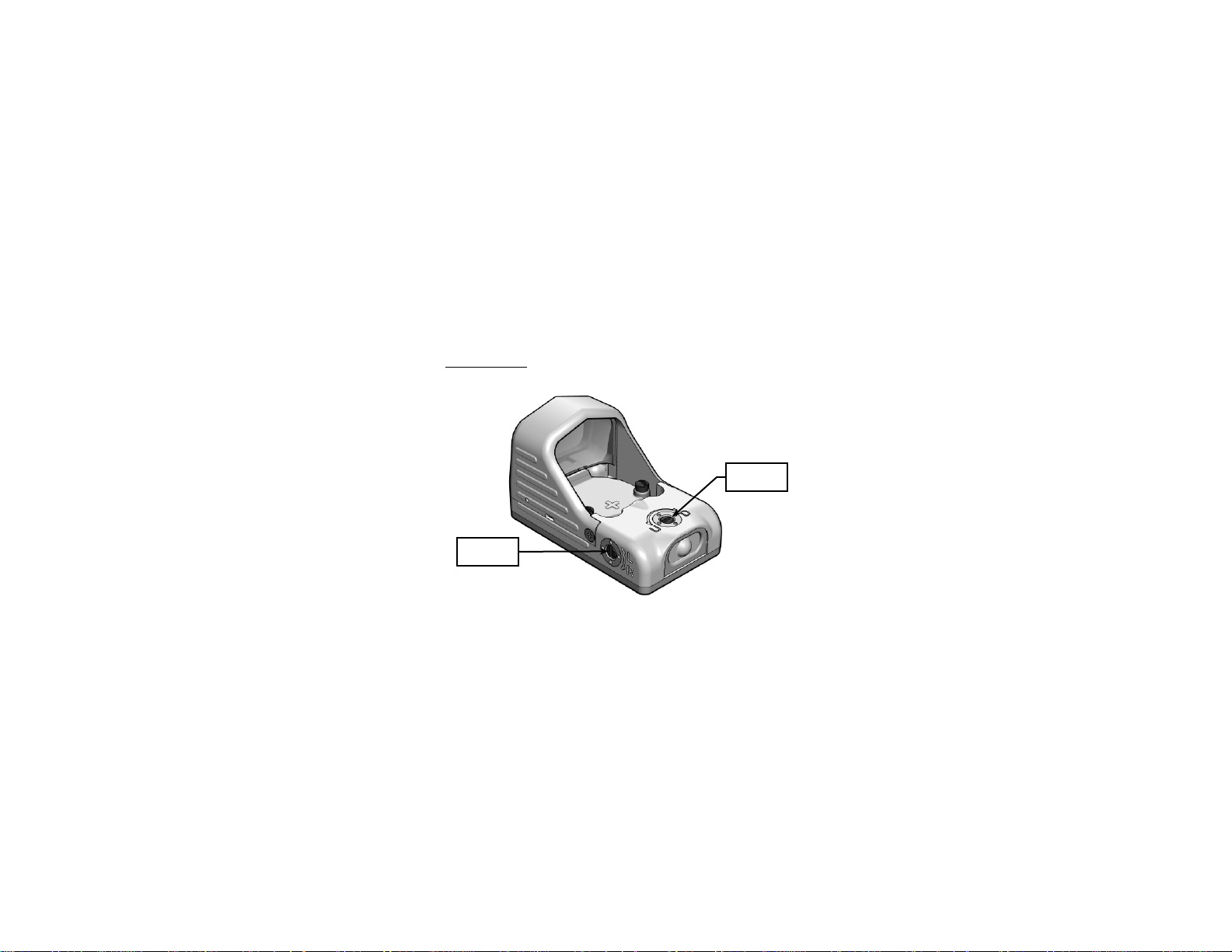
Adjuster
2.5.1 Boresight Adjusters . The MRDS is equipped with boresight adjusters, shown in Figure
2-3, for independent movement of the red dot in both azimuth and elevation.
Elevation
Adjuster
Azimuth
Figure 2-3 Boresight Adjusters
2-4
Page 19

Single Click Equivalents
10m
.30 cm
25m
.73 cm
50m
1.5 cm
100m
2.9 cm
Forcing the boresight adjusters beyond their end of travel may result in
permanent damage to the MRDS.
The adjusters have tactile detents that allow the operator to move the red dot in precise
increments of .29 mrad (1 MOA) per click. The adjusters are turned clockwise or
counterclockwise using a small slotted screwdriver. Markings on the MRDS housing
correspond to shot group movement. In practice, each click translates to moving the point of
impact of the round as follows:
2.5.2 Alignment Procedure for Infinite Parallel . The procedure below explains how to align the
MRDS to be parallel with the barrel of the host weapon on a 25-meter range. This “infinite
parallel” configuration is appropriate for many mission profiles with engagement ranges out to
approximately 50m. Zeroing the MRDS / weapon combination for greater distances should be
accomplished at an extended range using the procedure described in section 2.5.3.
CAUTION..
Table 2-1 Red Dot Adjustments
2-5
Page 20
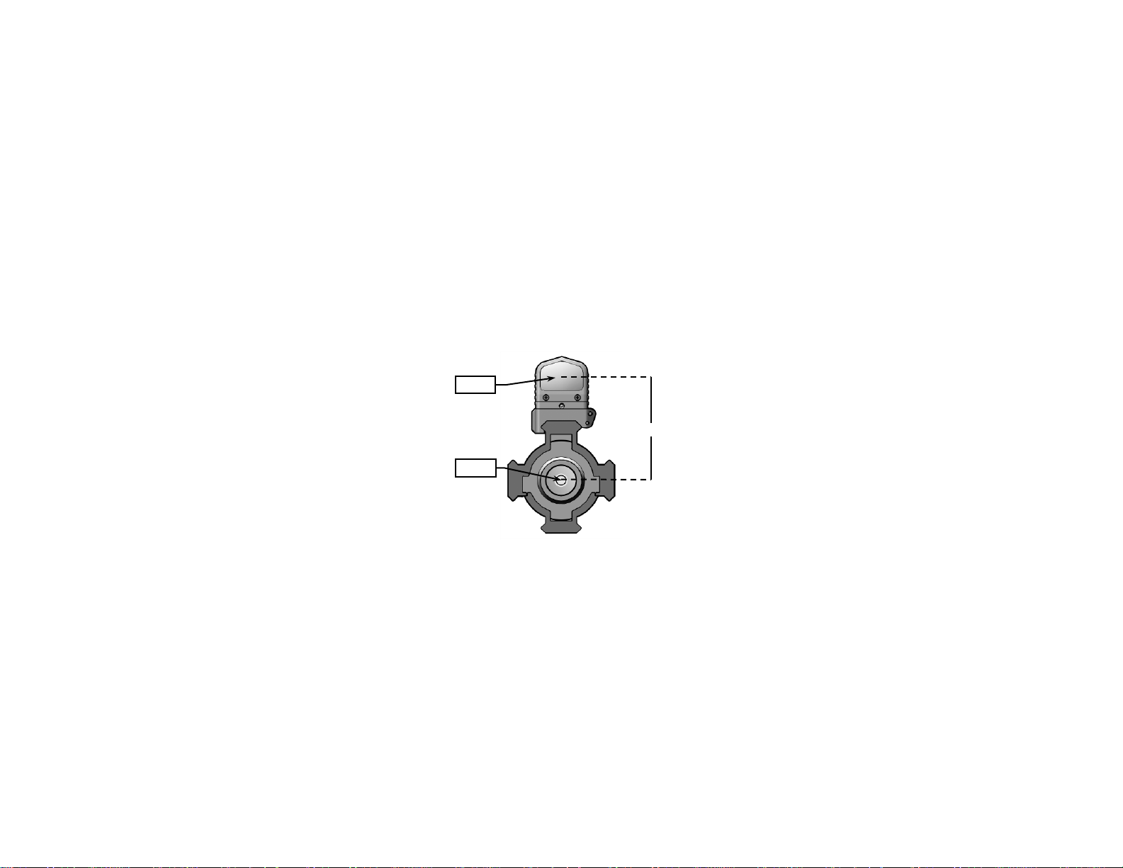
a. Use a ruler to measure the distance from the center of the weapon bore to the
Bore
6cm
center of the MRDS lens (see Figure 2-4). This distance will vary depending on the
MRDS mounting configuration being used. In this example, we will assume a
measured distance of 6cm.
Lens
Figure 2-4 Strike Point Calculation
2-6
Page 21

b. On a standard 25-meter zeroing target, mark the designated strike point. In this
example, measure 6cm down from the center of the target.
The designated strike point should be moved right or left if the MRDS is mounted
off-centered from the horizontal axis of the weapon barrel. If the MRDS is
mounted to the right of the barrel centerline, the strike point should be moved left
an equal distance. If the MRDS is mounted to the left of the barrel centerline, the
strike point should be moved right an equal distance.
c. Draw a designated strike zone around the strike point that corresponds in size to
an acceptable degree of accuracy (see Figure 2-5).
NOTE
2-7
Page 22
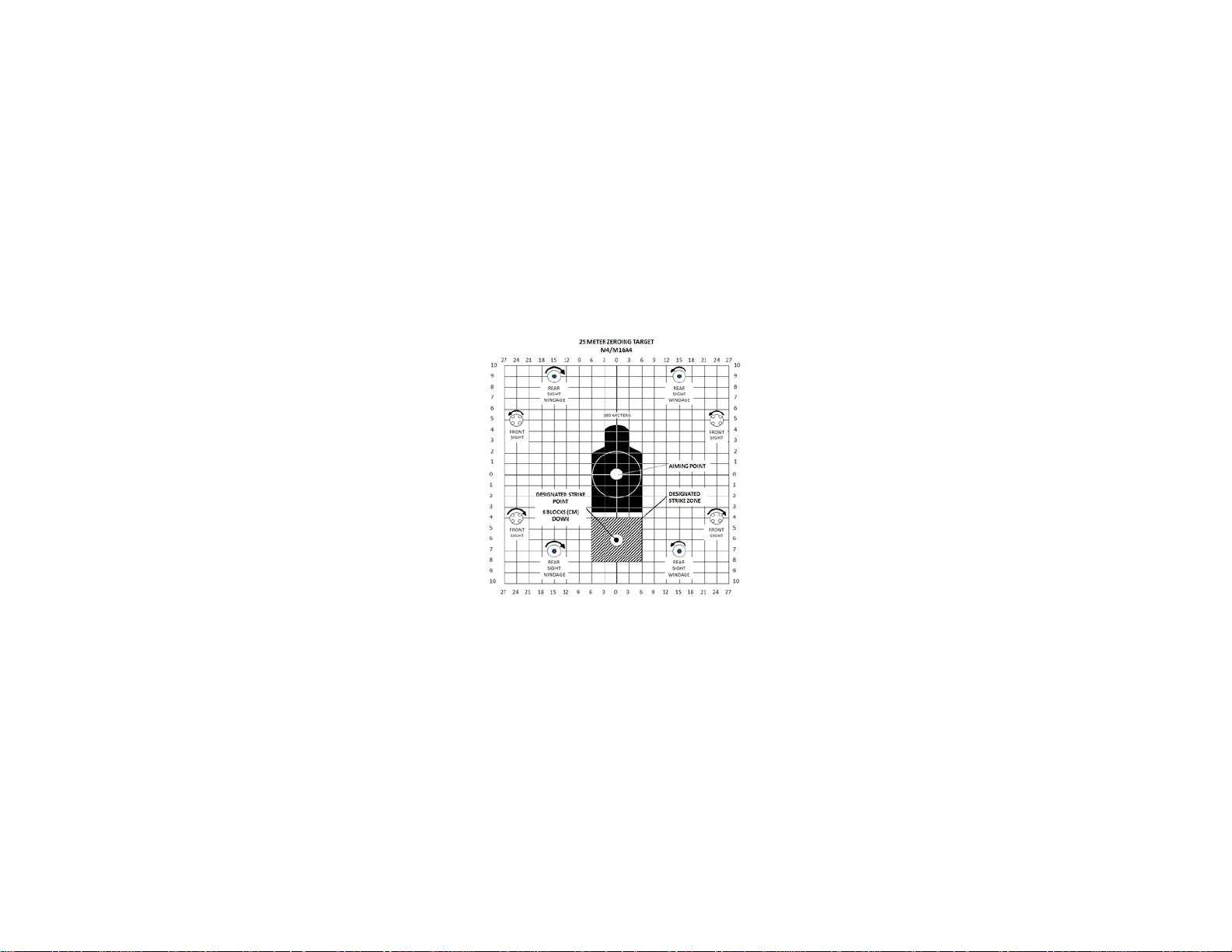
Figure 2-5 Designated Strike Zone
2-8
Page 23

d. Mount the target on an “E” silhouette or other suitable surface at 25 meters.
e. Press the MRDS pushbutton and adjust intensity of the red dot to a comfortable
level (see section 2.8).
f. Assume a good firing position and align the MRDS red dot with the center of the
target.
g. Fire a 3-round shot group and note the center of the shot group relative to the
designated strike point.
h. Rotate the boresight adjusters to move the center of the shot group to the
designated strike point.
i. Fire another 3-round shot group and observe the center of the new shot group
relative to the designated strike point.
j. When 2 out of 3 rounds are in the designated strike zone, the MRDS is aligned with
the barrel of the host weapon.
2.5.3 Zeroing at an Extended Range . The MRDS may be zeroed for a specific point of aim /
point of impact at an extended range. This is appropriate for mission profiles where the likely
engagement range is known, or for engagement ranges in excess of 50m.
a. On a suitable target, draw a designated strike zone around the center of the target
that corresponds in size to an acceptable degree of accuracy.
b. Place the target downrange at a known distance (e.g., 100m).
c. Press the MRDS pushbutton and adjust intensity of the red dot to a comfortable
level (see section 2.8).
2-9
Page 24

d. Assume a good firing position and align the MRDS red dot with the center of the
target.
e. Fire a 3-round shot group and note the center of the shot group relative to the
center of the target.
f. Rotate the boresight adjusters to move the center of the shot group to the center of
the target.
g. Fire another 3-round shot group and observe the center of the new shot group
relative to the designated strike zone.
h. When 2 out of 3 rounds are in the designated strike zone, the MRDS / weapon
combination is zeroed for that specific range.
2-10
Page 25
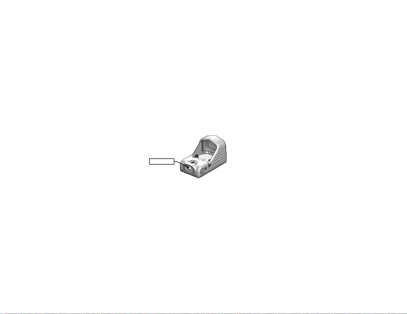
Pushbutton
SECTION II
2.6 FEATURES AND CONTROLS
Figure 2-6 shows the features and controls for the MRDS. This Section provides details
regarding their function and operation.
OPERATING PROCEDUR ES
2.7 POWER
If the MRDS is off, pressing (and holding) the pushbutton for less than one second will turn it
on. If the MRDS is on, pressing (and holding) the pushbutton for at least two seconds will turn
it off. Approximately two seconds must elapse between cycling the power on or off.
Figure 2-6 MRDS Features and Controls
2-11
Page 26

2.8 MODES OF OPERATION
A photodiode mode where the intensity of the red dot
selected when the MRDS is powered on.
lit environments.
Red dot is set to its lowest intensity level. This setting is
device back to Auto Gain mode.
With the MRDS turned on, each press of the pushbutton will sequentially step the device
through discrete modes of operation as shown in Table 2-2.
Mode Remarks
Auto Gain
High 1
High 2
Low 1
Table 2-2 Modes of Operation
automatically adjusts to changes in ambient lighting
conditions. This is the default mode and is automatically
Red dot is set to its highest intensity level.
Red dot is set to its second highest intensity level.
Red dot is set to a low intensity leve l appropr iate for dimly
Low 2
After 6 hours of continuous operation in High 1, High 2, Low 1, or Low 2
operating modes, the MRDS will automatically revert to the Auto Gain mode to
conserve power until another mode is selected by the operator.
appropriate for use with night vision devices. When in this
mode, pressing the pushbutton again will “loop” the
NOTE
2-12
Page 27

3.1 MAINTENANCE PROCEDURES
The operator should inspect the MRDS before each use and after it has been in extreme
conditions, such as prolonged exposure to intense temperatures. The following procedures
will extend the life of the MRDS and help ensure safe operation.
3.1.1 MRDS Housing . To clean the MRDS housing, rinse with water or mild soap and water
and then wipe dry with a soft cloth. Clean around buttons and adjusters with a cotton swab.
3.1.2 Optical Surfaces . Optical surfaces should be inspected for foreign material. Remove
any large particles or loose dirt using air or a lens brush. Fine cleaning should be performed
using lens tissue and lens cleaning solution or the flexible cleaning tip of the lens pen. Avoid
using excessive force as this may scratch the lens.
To ensure proper functioning of the MRDS, particular attention must be paid to
the cleanliness of the Red Dot Aperture shown in Figure 3-1.
MAINTENANCE AND SERVICING
CHAPTER 3
MAINTENANCE INSTRUCTIONS
SECTION I
NOTE
3-1
Page 28
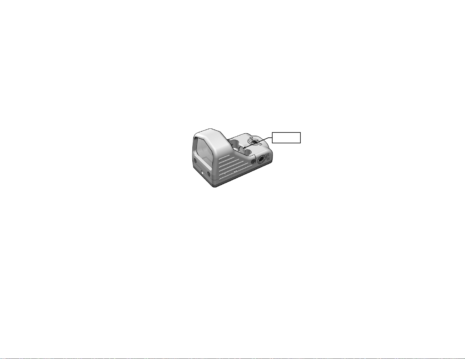
Red Dot
Aperture
Figure 3-1 Red Dot Aperture
3-2
Page 29

3.2 SERVICE / REPAIR
3.2.1 For service, repair, or replacement, first email [email protected] or call
toll –free 1-877-744-4803.
3.2.2 To assist with determining if the item is repairable, the following information will be
requested:
a. Serial number of the defective item;
SERVICE / PACKING AND UNPACKING
SECTION II
b. Thorough description of the malfunction, defect, or damage; and
c. If known, an explanation as to how the malfunction, defect, or damage occurred.
If the item is determined to be Beyond Economical Repair, follow applicable replacement
procedures through your Property Officer. If it is determined that the item is under warranty, or
should be returned for repair, a Return Material Authorization (RMA) number will be provided.
3.2.3 When returning the MRDS for service / repair, the following procedures should be
followed to prevent any additional damage:
a. Be sure that the MRDS is free of all contaminants such as dirt or any other foreign
material.
b. Remove the battery.
3-3
 Loading...