

Page 1
CQT-TM-ITI
OPERATOR MANUAL
FOR THE
CLIP-ON NIGHT VISION DEVICE – THERMAL 2
(CNVD-T2)
Rev. 4 10 September 2012
Page 2

Page 3

SAFETY SUMMARY
GENERAL
This manual contains operating instructions and
maintenance procedures which may cause injury or death to
personnel, or damage to equipment if not properly followed.
Prior to performing any task, the WARNINGs, CAUTIONs
and NOTEs included in that task shall be reviewed and
understood.
DEFINITIONS
Highlights an essential operating or maintenance
procedure, practice, condition or statement, which,
if not strictly observed, could result in i njury to, or
death of, personnel or long term health hazards.
Highlights an essential operating or maintenance
procedure, practice, condition or statem ent, which,
if not strictly observed, could res ult in damage to,
or destruction of, equipment or loss of mission
effectiveness.
Highlights an essential operating or maintenance
procedure, condition or statement.
WARNING
CAUTION
NOTE
i
Page 4

SAFETY PRECAUTIONS
Safety
Class
OD4
MPE
IR Laser Pointer
1 0 0
-
The following general safety precautions supplement the
specific WARNINGs, CAUTIONs and NOTEs that appear
elsewhere in this manual.
WARNING
The Clip-On Night Vision Device – Thermal 2
(CNVD-T2) emits invisible laser radiation in the
form of an Infrared (I R) Laser Pointer designated
Safety Class 1. Nominal Ocular Hazard Distances
(NOHD) for safe operation are listed in Table i-1.
Table i-1 Nominal Ocular Hazard Distances for Safe
Laser/Mode
Operation
1
NOHD2 ENOHD
3
1
Laser Safety Classification per IEC 60825-1 of 2007-03
2
Nominal Ocular Hazard Distance without magnifying optics
3
Extended Nominal Ocular Hazard Distance with standard 7x50
magnifying optics
4
Optical Density (OD) calculated for Condition 3 (unaided) at .01m from exit
aperture as a function of Maximum Permissible Exposure (MPE)
WARNING
• Do not stare into the laser beam.
• Do not look into the laser beam through binoculars
or telescopes.
• Do not point the laser beam at mirror-like surfaces.
• Do not shine the laser beam into another indivi dual s’
eyes.
ii
Page 5

WARNING
IR lasers are detectable by an enem y using night
vision devices. Detection is easier in smoky,
foggy, or rainy conditions. To reduce the ri sk of
detection by an enemy using night vision devices,
avoid prolonged activation of the CNVD-T2’s IR
Laser Pointer.
WARNING
Emission of stray light from the eyepiece (even
with the eyecup installed) may be detectable by
the enemy.
WARNING
Do not touch, ingest, or inhale particles or
fragments of a broken thermal objective lens.
Thermal lenses contain material that may cause
irritation to eyes, skin, upper and lower respirat ory
tracts, or gastrointestinal t ract. If contacted, flush
eyes or skin with large amounts of water. If
ingested, DO NOT induce vomiting. Rinse m outh
with water and give victim 2-4 cupf uls of milk or
water. Fragments of the lens may be sharp
enough to cut personnel if touched.
WARNING
Activating Z OOM 2X when the CNVD-T2 is used
in-line with other optical sights may introduce an
error in the aiming function of those devices.
WARNING
Do not use the CNVD-T2 with a mix of old and
new batteries, or batteries of different brands.
iii
Page 6

WARNING
• Do not short circuit, puncture, incinerate, or
disassemble batt eri es.
• Do not attempt to recharge batteries.
• Prior to use, inspect all batteries for cracks, dents,
leakage, or bulging. Never install a defective battery
in the CNVD-T2.
WARNING
Lithium batteries can explode or cause burns if
disassembled, shorted, recharged, or exposed to
water, fire, or high temperatures (above 100°C or
212°F). Do not place loose batteries in a pocket
or other container containing metal objects. Do
not store batteries with hazardous or combustible
materials. Store in a cool, dry, ventilated area.
WARNING
Use of off-brand batteries poses a risk of fire or
explosion. Ensure that only batteries produced by
a well-known battery m anufacturer are installed in
the CNVD-T2. These batteries are specifically
designed for use in high performanc e, high-drain
devices, and contain built-in fault and heat
protection features.
WARNING
Use of incorrect batteries poses a risk of fire or
explosion. Be aware that batteries do exist with
similar physical characteristics to the DL123A
battery, but with a different voltage and/ or polarity
path. Ensure that only 3V lithium batteries with a
raised positive (+) terminal are installed in the
CNVD-T2.
iv
Page 7

WARNING
The CNVD-T2 is designed to be used with
destructive weapon systems. Improper operation
or misuse of the CNVD-T2 with these weapon
systems could lead to personal injury or death of
either the operator or other persons within
weapons range. Safe firearms handling
procedures must be practiced at all times.
WARNING
Remove the CNVD-T2 from the weapon before
inspecting, cleaning, or performing other
maintenance functions.
WARNING
Isopropyl alcohol is flammable and toxic. To avoid
injury, keep away from open fire and use in a well
ventilated area.
CAUTION
Use of acetone or gun cleaning agents containing
perchloroethylene or methylene chloride may
permanently damage the CNVD-T2 system.
CAUTION
Pointing the CNVD-T2 at the sun (even when
powered off) without the lens cover installed may
damage internal imaging components.
CAUTION
Do not ship or store the CNVD-T2 with batteries
installed.
v
Page 8

TABLE OF CONTENTS
SAFETY SUMMARY ....................................................................... i
TABLE OF CONTENTS ................................................................ vi
LIST OF FIGURES ...................................................................... viii
LIST OF TABLES ........................................................................ viii
CHAPTER 1 ...................................................................................... 1-1
INTRODUCTION ......................................................................... 1-1
SECTION I .............................................................................. 1-1
GENERAL INFORMATION ............................................... 1-1
1.1 SCOPE .................................................................. 1-1
1.2 MODEL NUMBER AND EQUIPMENT NAME ...... 1-2
1.3 MANUFACTURER ................................................ 1-2
1.4 PURPOSE OF EQUIPMENT ................................ 1-2
1.5. ABBREVIATIONS AND ACRONYMS ................. 1-2
SECTION II ............................................................................. 1-4
EQUIPMENT DESCRIPTION ........................................... 1-4
1.6 SYSTEM DESCRIPTION ...................................... 1-4
1.7 TECHNICAL SPECIFICATIONS .......................... 1-5
1.8 LIST OF MAJOR COMPONENTS ........................ 1-6
CHAPTER 2 ...................................................................................... 2-1
OPERATING INSTRUCTIONS ................................................... 2-1
vi
1.9 FEATURES AND CONTROLS ............................. 1-9
SECTION I .............................................................................. 2-1
PREPARATION FOR USE ............................................... 2-1
2.1 PREPARATION FOR USE ................................... 2-1
2.2 BATTERY HANDLING .......................................... 2-2
2.3 MOUNTING PROCEDURES ................................ 2-3
2.4 LENS ACCESSORIES .......................................... 2-6
SECTION II ............................................................................. 2-7
OPERATING INSTRUCTIONS ......................................... 2-7
2.5 POWER ................................................................. 2-7
2.6 BUTTON FUNCTIONS ......................................... 2-8
2.7 BRIGHTNESS ADJUSTMENT ............................. 2-9
2.8 CONTRAST (GAIN) ADJUSTMENT................... 2-10
2.9 FOCUS ADJUSTMENT ...................................... 2-11
2.10 IR LASER POINTER ......................................... 2-12
2.11 STARTUP PROCEDURES ............................... 2-12
2.12 SHUTDOWN PROCEDURES .......................... 2-13
Page 9

TABLE OF CONTENTS (Continued)
SECTION III .......................................................................... 2-14
SYSTEM MENUS ............................................................ 2-14
2.13 GENERAL ......................................................... 2-14
2.14 ZOOM 1X / ZOOM 2X ....................................... 2-15
2.15 WHITE HOT (WHOT) / BLACK HOT (BHOT) .. 2-15
2.16 CALIBRATION (CAL) ........................................ 2-16
2.17 RETICLE INTENSITY (RETINT) ...................... 2-17
2.18 RETICLE (RET) ................................................ 2-18
2.19 PICTURE (PIC) ................................................. 2-19
2.20 REVIEW (REV) ................................................. 2-20
2.21 RS170 / VGA ..................................................... 2-21
2.22 EXIT .................................................................. 2-21
SECT IO N IV ......................................................................... 2-22
ALIGNMENT / ZEROING ................................................ 2-22
2.23 ALIGNMENT / ZEROING PROCEDURES ....... 2-22
SECTION V .......................................................................... 2-26
IMAGE DOWNLOAD / VIEWING .................................... 2-26
2.24 IMAGE ADAPTER CABLE................................ 2-26
2.25 VIEWING LIVE IMAGERY ................................ 2-27
CHAPTER 3 ...................................................................................... 3-1
MAINTENANCE AND SERVICING ............................................ 3-1
APPENDIX A.................................................................................... A-1
END ITEM COMPONENTS AND REPAIR PARTS ................... A-1
APPENDIX B.................................................................................... B-1
ACCESSORIES .......................................................................... B-1
2.26 RETRIEVING STORED IMAGES ..................... 2-28
SECTION I .............................................................................. 3-1
MAINTENANCE AND TROUBLESHOOTING .................. 3-1
3.1 TROUBLESHOOTING .......................................... 3-1
3.2 INSPECTION / CLEANING................................... 3-3
3.3 CORRECTIVE MAINTENANCE ........................... 3-5
SECTION II ........................................................................... 3-11
SERVICE / PACKING AND UNPACKING ...................... 3-11
3.4 RETURN INSTRUCTIONS ................................. 3-11
3.5 WARRANTY INFORMATION ............................. 3-12
3.6 NON-WAR RANTY INFOR MAT ION .................... 3-12
A.1 SCOPE ................................................................ A-1
A.2 END ITEM COMPONENTS................................. A-2
A.3 REPAIR PARTS .................................................. A-3
B.1 SCOPE ................................................................ B-1
vii
Page 10

LIST OF FIGURES
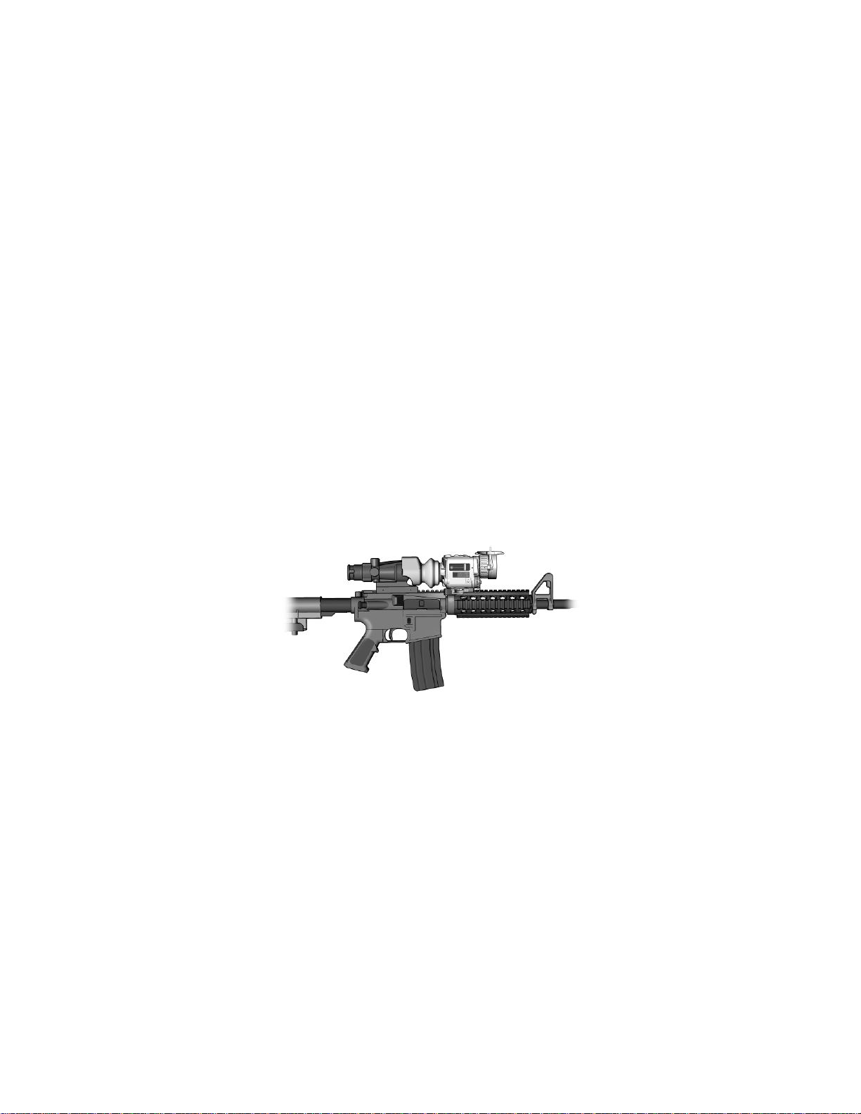
Figure 1-1. CNVD-T2 Mounted on M4. ............................................ 1-1
Figure 1-2. Major Components. ....................................................... 1-6
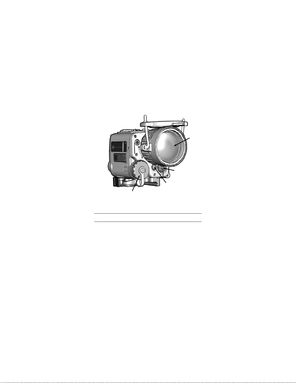
Figure 1-3. Features and Controls (Rear View). ............................. 1-9
Figure 1-4. Features and Controls (Front View). ........................... 1-10
Figure 2-1. Battery Installation. ........................................................ 2-2
Figure 2-2. Throw-Lever Mounting Bracket. .................................... 2-3
Figure 2-3. CNVD-T2 Mounted with ACOG® .................................. 2-5
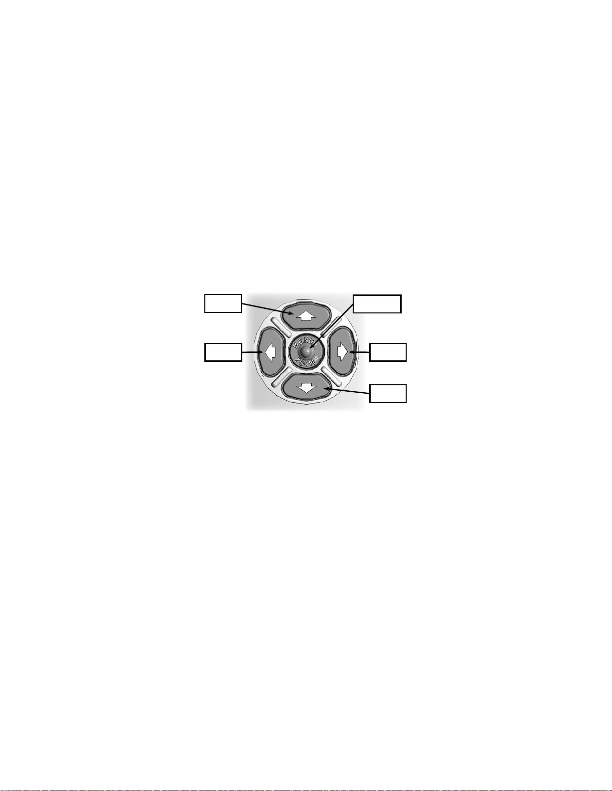
Figure 2-4. CNVD-T2 Keypad.......................................................... 2-8
Figure 2-5. Brightness Control. ........................................................ 2-9
Figure 2-6. Contrast (Gain) Control. .............................................. 2-10
Figure 2-7. Main Menu. .................................................................. 2-14
Figure 2-8. Reticle Intensity Control. ............................................. 2-17
Figure 2-9. Menu - Reticle Sub-Menu. .......................................... 2-18
Figure 2-10 Reticle Position Adjustment ....................................... 2-19
Figure 2-11. Menu – Review Sub-Menu. ....................................... 2-20
Figure 2-12. Strike Point Calculation. ............................................ 2-23
Figure 2-13 Designated Strike Zone .............................................. 2-24
Figure 2-14. Image Adapter Cable. ............................................... 2-26
Figure 3-1. Adjusting Throw-Lever Tension. ................................... 3-6
Figure 3-2. Replacing Objective Lens Cover / Straps. .................... 3-6
Figure 3-3. Batttery Compartment O-Ring....................................... 3-8
Figure 3-4. Battery Cap / Battery Cap Lanyard. .............................. 3-9
Figure A-1. End Item Components ................................................. A-2
Figure A-2. CNVD-T2 Assembly ..................................................... A-3
Table i-1 Nominal Ocular Hazard Distances for Safe Operation ....... ii
Table 1-1. Technical Specifications. ................................................ 1-5
Table 1-2. List of Major Com po nen ts . ............................................. 1-7
Table 1-3. List of Features and Cont rols. ...................................... 1-10
Table 2-1. Reticle Adjustments. ..................................................... 2-22
Table 2-2. Image Adapter LED Indicators. .................................... 2-29
Table 3-1. Troubleshooting Procedures. ......................................... 3-1
Table A-1. List of End Item Components........................................ A-2
Table A-2. List of Repair Parts........................................................ A-3
Table B-1. List of Accessories. ....................................................... B-1
LIST OF TABLES
viii
Page 11
CHAPTER 1
INTRODUCTION
SECTION I
GENERAL INFORMATION
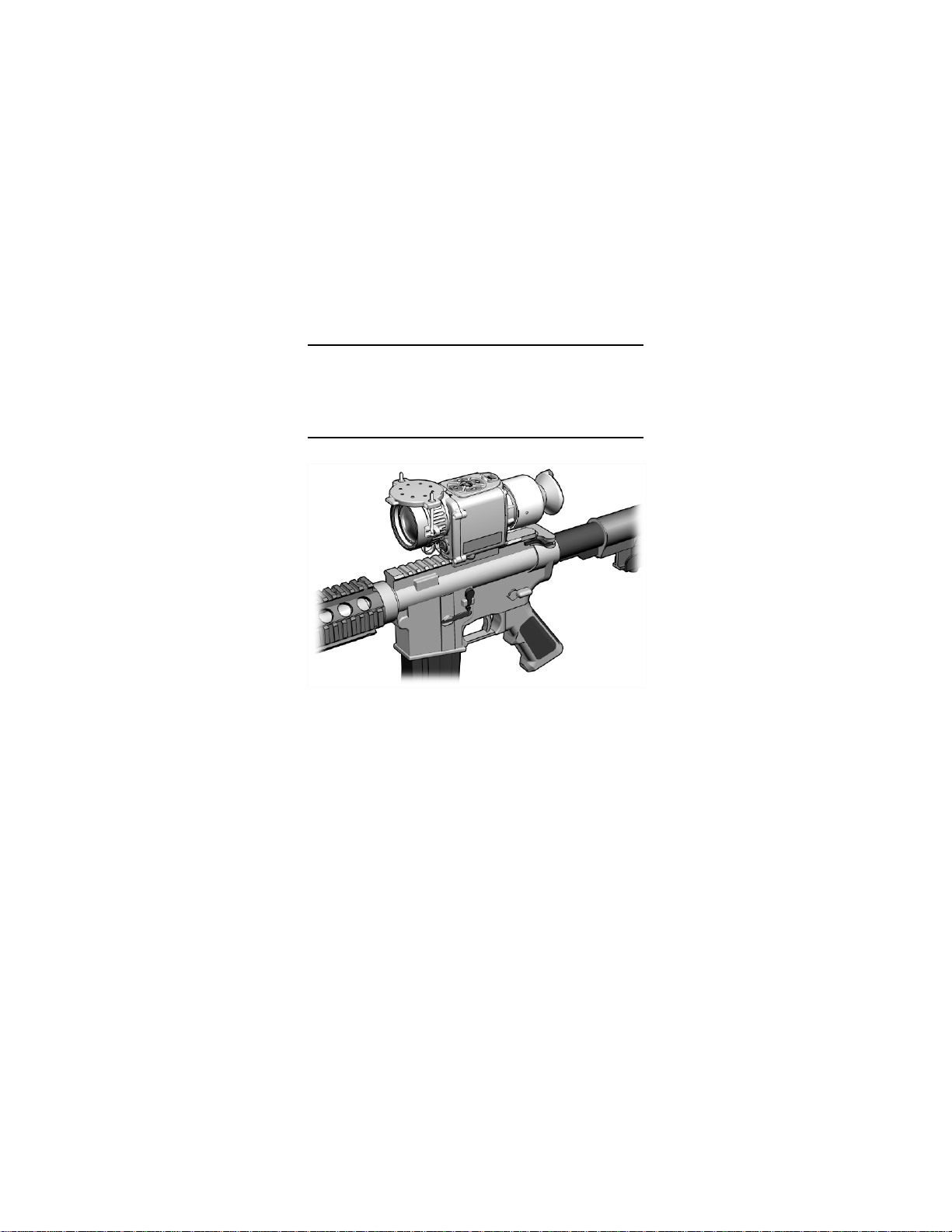
Figure 1-1. CNVD-T2 Mounted on M4.
1.1 SCOPE
This manual is intended for use by operators of the Clip-On
Night Vision Device - Thermal 2 (CNVD-T2). It provides a
system description, operational procedures, and
maintenance responsibilities. Complete familiarization with
this manual prior to using the equipment will ensure safe
operation and maximum effectiveness of the CNVD-T2.
1-1
Page 12

1.2 MODEL NUMBER AND EQUIPMENT NAME
ACOG
Advanced Combat Optical Gunsight
AZ
Azimuth
BHOT
Black Hot (Menu Item)
BNC
Bayonet Neill-Concelman
C
Celsius
CAL
Calibration (Menu Item)
cm
Centimeter
CNVD-T2
Clip-On Night Vision Device – Thermal 2
EL
Elevation
F
Fahrenheit
CQT-001-A12, CNVD-T2, 6V, Tan
1.3 MANUFACTURER
L-3 Communications Corporation
Warrior Systems Division
Insight Operations
9 Akira Way
Londonderry, NH 03053 USA
1.4 PURPOSE OF EQUIPMENT
The CNVD-T2 is a battery operated, weapon-mounted,
thermal imaging device with an integrated Infrared (IR) Laser
Pointer and digital camera. It allows for observation, target
identification, and target acquisition during the day or in
adverse conditions such as light rain or snow, dry smoke,
and low light to total darkness.
1.5. ABBREVIATIONS AND ACRONYMS
Abbreviations and acronyms used in this manual are listed
as follows:
ENOHD Extended Nominal Ocular Hazard Distance
1-2
Page 13

IEC
International Electrotechnical Commission
IR
Infrared
ITAR
International Traffic in Arms Regulations
m
Meter
MPE
Maximum Permissible Exposure
mrad
Milliradians
nm
Nanometers
NOHD
Nominal Ocular Hazard Distance
OD
Optical Density
PC
Personal Computer
PIC
Picture (Menu Item)
QTY
Quantity
RECAL
Recalibrate
RET
Reticle (Menu Item)
RETINT
Reticle Intensity (Menu Item)
RMA
Return Material Authorization
TBD
To Be Determined
USB
Universal Serial Bus
V
Volt
VGA
Video Graphics Array
WHOT
White Hot (Menu Item)
1.5 ABBREVIATIONS AND ACRONYMS (Continued)
LED Light Emitting Diode
N/A Not Applicable
POS (Reticle) Position (Menu Item)
REV Revie w (Menu Item)
µW Microwatts
1-3
Page 14

EQUIPMENT DESCRIPTION
SECTION II
1.6 SYSTEM DESCRIPTION
The CNVD-T2 is a battery operated, weapon-mounted,
thermal imaging device with an integrated IR Laser Pointer
and digital camera. It may be used as a handheld device,
mounted to a weapon in a stand-alone configuration, or used
in-line with a magnified day optic.
The thermal imaging capability of the CNVD-T2 allows for
observation and target identification under adverse
conditions such as light rain or snow, dry smoke, and low
light to total darkness. The unit will not allow the user to see
through glass, water, or heavy rain / snow.
The integrated Laser Pointer provides a means of marking
potential targets in low light or complete darkness for handoff
to individuals using night vision devices.
With the integrated digital camera, the CNVD-T2 allows for
acquisition, storage, download, and recall of viewed thermal
images. Thermal images may also be transferred to a
personal computer (PC) using the Image Adapter Cable.
The CNVD-T2 can be mounted to weapons equipped with a
MIL-STD-1913 rail.
It is a ruggedized system designed for operation in battlefield
environments.
1-4
Page 15

WEIGHT AND DIMENSIONS
Length
5.3 inches (13.5 cm)
Width
2.9 inches (7.4 cm)
Height
3.4 inches (8.6 cm)
POWER
Batteries
2 DL123A lithium batteries
* Battery Life
≥ 4.5 hours
Startup Time
< 6 seconds
IR LASER POINTER
Beam Divergence
0.5 mrad (± 0.3 mrad)
Wavelength
830 nm (+20 / -10 nm )
OTHER PARAMETERS
Field of View
12° diagonal (± 4%)
Operating Temperatures
-27°F (-32°C) to +122°F (+50°C)
Storage Temperatures
-40°F (-40°C) to +160°F (+71°C)
Immersion
66 feet (20m) for 2 hou rs
Objective Focus
2m to infinity
1.7 TECHNICAL SPECIFICATIONS
Weight
(with batteries)
Table 1-1. Technical Specifications.
< 21.5 ounces (609.5 grams)
Output Power 560 µW (± 100 µW)
* Performance will vary depending on actual environmental and
atmospheric conditions.
1-5
Page 16
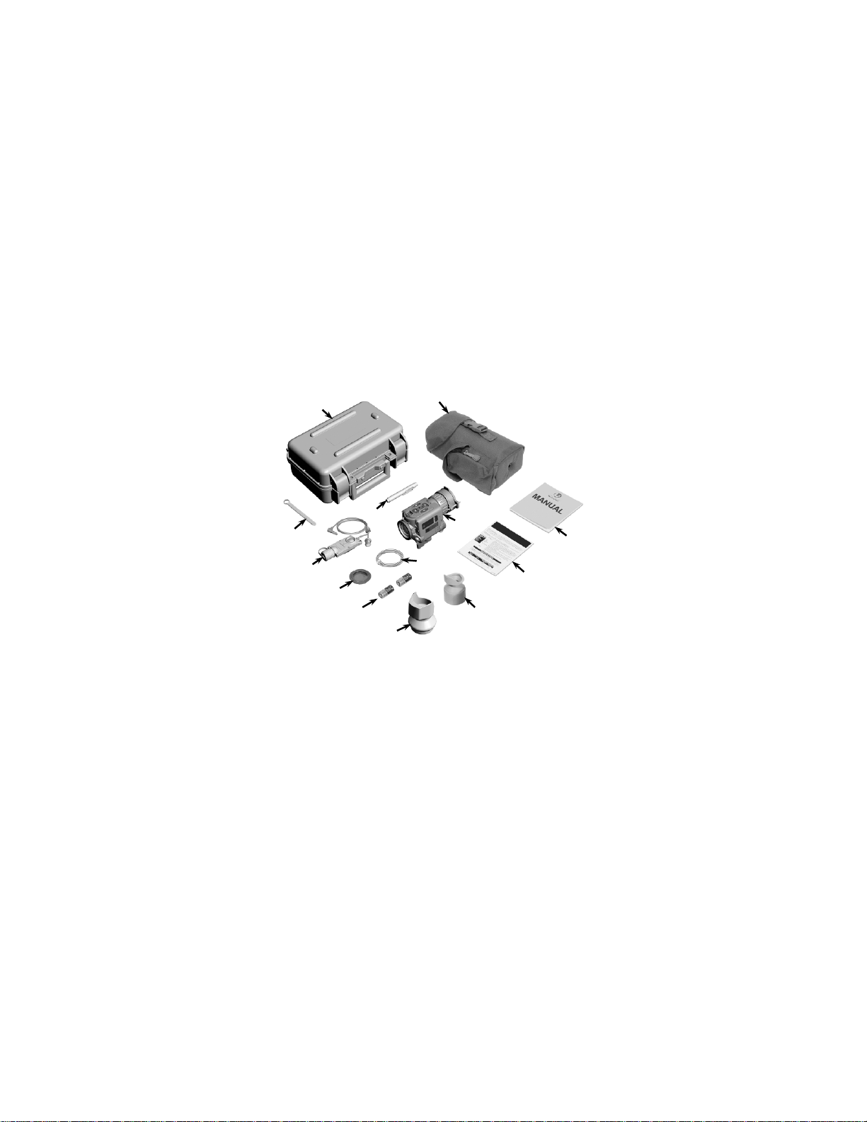
1.8 LIST OF MAJOR COMPONENTS
1 2 8
3 9 10
6
12
11
The CNVD-T2 system includes the components shown in
Figure 1-2. Table 1-2 provides a brief functional description
of each item. The “Key” column in Table 1-2 corresponds to
the label numbers in Figure 1-2.
1-6
13
5 7
Figure 1-2. Major Components.
4
Page 17

Major
Component
1
Transit / Storage
Allows for watertight storage and/or
2
Soft Carrying
Case
Protects the CNVD-T2 and accessories
while in a field environment.
3
Operator Manual
Provides detailed ope rating and
CNVD-T2.
4
Guide
procedures for the CNVD-T2.
Removable
stray light from the eyepiece.
mounted in-line with other optical sights.
7
Batteries,
Two 3V DL123A lithium batteries used
8
Night Adaptive
When attached, prevents fogging of the
environments.
viewed or downloaded.
1.8 MAJOR COMPONENTS (Continued)
Key
Table 1-2. List of Major Components.
Function
5
6
9
Case
Quick Reference
Eyecup,
Interface Hood
DL123A (2)
Filter / Demist
Shield
Image Adapter
Cable
shipping of the CNVD-T2 and
accessories.
maintenance instructions specific to the
Provides at-a-glance op era ti n g
When attached, reduces emission of
Used to improve light security and
image quality when the CNVD-T2 is
to power the CNVD-T2.
eyepiece and reduces backlighting and
loss of night vision in low light
Used to connect the CNVD-T2 to an
external monitor for viewing live
imagery, or to connect to a PC so that
captured thermal images may be
1-7
Page 18

1.8 MAJOR COMPONENTS (Continued)
Major
Component
10
Box Wrench, 3/8”
Used to adjust the tension of the throw-
11
Lens Pen
Used to clean the optical lenses of the
12
CNVD-T2
A thermal imaging device used for
or in adverse conditions.
13
device.
Table 1-2. List of Major Components (Continued).
Key
lever mounting bracket.
CNVD-T2.
Function
Assembly
Neck Cord Worn around the neck to prevent loss of
observation, target identification, and
passive target acquisition during the day
the CNVD-T2 when used as a handheld
1-8
Page 19
5 6 7
4
1.9 FEATURES AND CONTROLS
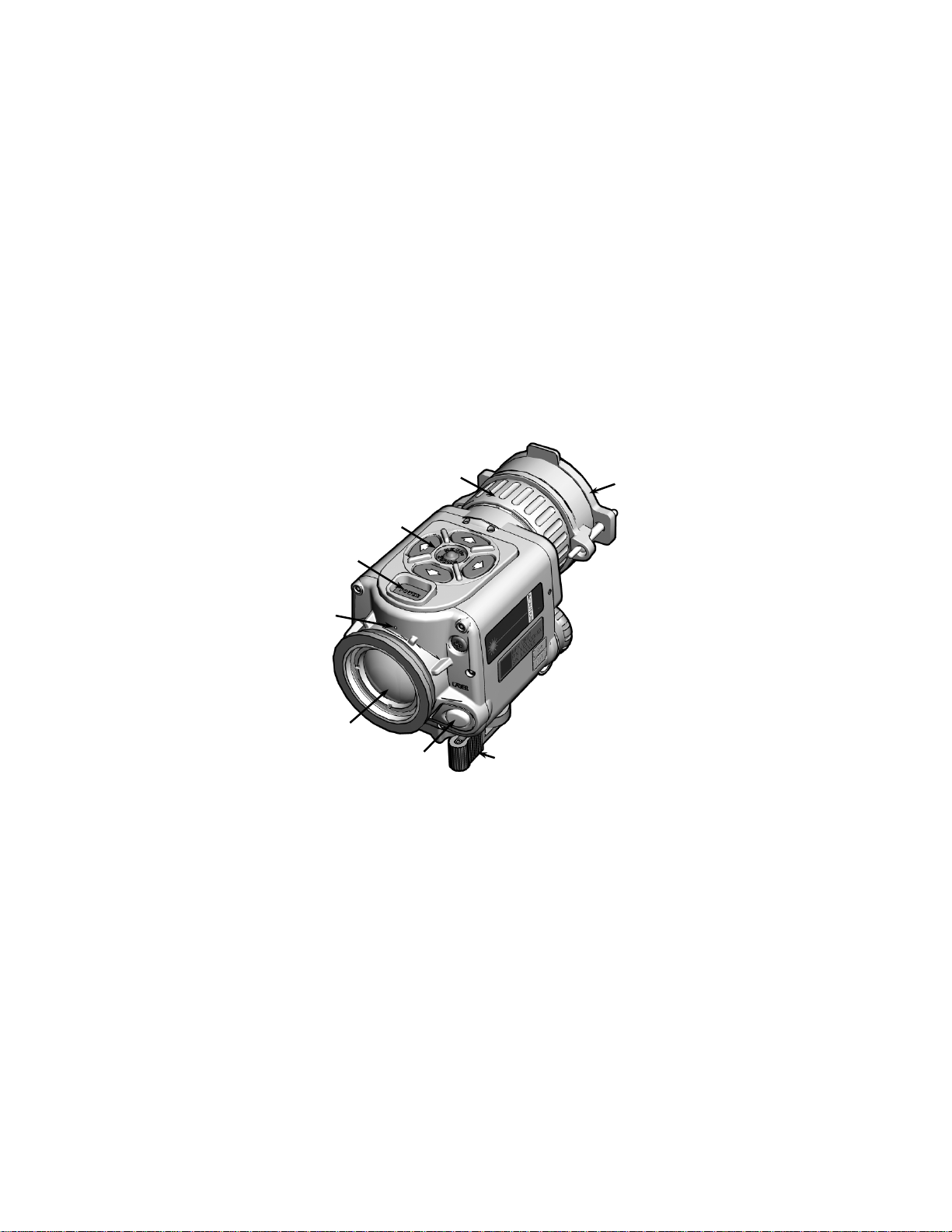
Figures 1-3 and 1-4 show the features and controls for the
CNVD-T2. Table 1-3 provides a brief functional description
of each item. The “Key” column in Table 1-3 corresponds to
the label numbers in Figures 1-3 and 1-4.
3
2
1
8
Figure 1-3. Features and Controls (Rear View).
1-9
Page 20
1.9 FEATURES AND CONTROLS (Continued)
Control/
Indicator
2
POWER Button
3
Keypad
Several multifunction buttons that allow
CNVD-T2.
9
10
11
12
Figure 1-4. Features and Controls (Front View).
Table 1-3. List of Features and Controls.
Key
1
Laser LED A Light Emitting Diode (LED) used to
indicate when the CNVD-T2 is emitting
laser energy.
Used to power the CNVD-T2 on and off.
for navigation of the system menus and
provide the primary user interface for the
Function
1-10
Page 21

Control/
Indicator
4
Objective Focus
Used to focus the CNVD-T2 for the
5
Objective Lens
Used to protect the objective lens and
possible damage.
6
Throw-Lever
Mounting Bracket
Secures the CNVD-T 2 to a wea pon
equipped with a MIL-STD-1913 rail.
7
Laser Button
Used to activate the IR Laser Pointer.
viewed by the operator.
imaging detector.
10
Video Jack / Jack
Provides a cable interface for viewing
11
IR Laser Pointer
Provides a means of marking potential
vision devices.
12
Battery Cap /
Compartment
Provides secure housing for the two 3V
lithium batteries that power the CNVD-T2.
1.9 FEATURES AND CONTROLS (Continued)
Table 1-3. List of Features and Controls (Continued).
Key
Function
8
9
Ring
Cover
Eyepiece
Objective Lens
Plug
viewing distance being observed.
internal imaging components from
Allows the thermal image, as well as the
system menus and symbology, to be
Collects thermal energy from the viewed
scene and focuses it upon a thermal
CNVD-T2 thermal imagery on an external
monitor or to transfer captured thermal
images to a PC.
targets in low light or complete darkness
for handoff to individuals using night
1-11
Page 22

1-12
Page 23

CHAPTER 2
OPERATING INSTRUCTIONS
2.1 PREPARATION FOR USE
Unpacking the Equipment
Open the soft carrying case and verify that all major
components listed in Table 1—2 are present. Check the
CNVD-T2 assembly to ensure the following additional items
are installed:
a. Battery Cap Assembly
b. Video Jack Plug
c. Objective Lens Cover (and straps)
If any of the major components or items listed above are
missing, seek guidance from the equipment issuing
authority.
Inspection of the Equipment
Before use, inspect all pieces of equipment for any damage
such as cracks, loose parts, faulty cables, or other visible
defects. If any damage or defects are noted, seek guidance
from the equipment issuing authority.
SECTION I
PREPARATION FOR USE
2-1
Page 24
2.2 BATTERY HANDLING
Battery Inspection
Before installation, inspect the batteries for any cracks,
dents, leakage, or bulging. Never install a defective battery
in the CNVD-T2.
Battery Installation
CAUTION
Do not ship or store t he CNVD-T2 with batteries
installed.
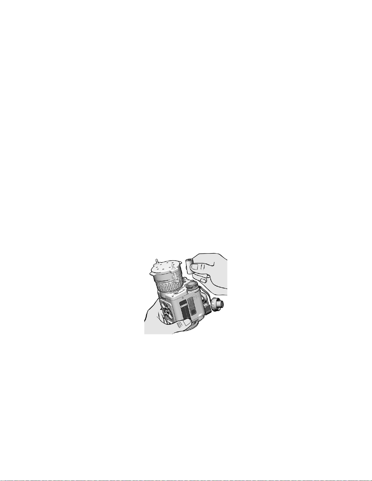
Proper battery orientation is clearly marked on the CNVD-T2
housing. Unscrew the battery cap and install the first
DL123A lithium battery. Tilt the CNVD-T2 t o allow the
battery to slide into the battery compartment, thereby
providing space to insert the second battery. Install the
second battery, then replace and screw in the battery cap.
2-2
Figure 2-1. Battery Installation.
Page 25

RECOIL LUG
THROW-LEVER
LEVER LOCK
2.2 BATTERY HANDLING (Continued)
Low Battery Indicator
A low battery message will appear in the eyepiece display
when approximately 20 minutes of continuous operation
remain. If the batteries are not replaced promptly when the
“LOW POWER” message appears, the display quality will
deteriorate rapidly.
2.3 MOUNTING PROCEDURES
Mounting Bracket
The CNVD-T2 is equipped with a throw-lever mounting
bracket that is designed for direct attachment to weapons
with a MIL-STD-1913 rail.
Figure 2-2. Throw-Lever Mounting Bracket.
2-3
Page 26

2.3 MOUNTING PROCEDURES (Continued)
Mounting Instructions
WARNING
Be sure the weapon is CLEAR and SAFE before
proceeding.
NOTE
The CNVD-T2 may be placed at any position
(forward and aft) on the rail that is most
convenient for the operator. If, however, the
CNVD-T2 is removed from the rail, the operator
should note the position at which it was zeroed,
and return it to that same position to ensure that
zero is retained.
1. Pull the lever lock out to the full open position.
2. Swing the throw-lever toward the front (objective lens) of
the CNVD-T2 to allow the mounting bracket sufficient
space to fit over the MIL-STD-1913 rail.
3. Position the mounting bracket over the rail ensuring that
the recoil lug is properly seated in the desired recoil
groove of the rail.
CAUTION
If too much or too little force is required to perform
step 4, the throw-lever must be adjusted to
properly secure to the rail of the host weapon.
See section 3.3 for adjustment procedures.
4. While pushing down and forward on the CNVD-T2, swing
the throw-lever toward the back (eyepiece) of the
CNVD-T2 until it is snug against the mounting bracket.
2-4
Page 27
2.3 MOUNTING PROCEDURES (Continued)
5. Push the lever lock in to engage the locking mechanism.
Mounting In-Line with Other Opt ics
When the CNVD-T2 is mounted in-line with another optical
sight, the interface hood may be used to improve light
security and image quality.
1. Mount the day optic to the weapon rail per manufacturer’s
operating instructions.
2. Pull the circular end of the interface hood over the
eyepiece assembly of the CNVD-T2.
3. Mount the CNVD-T2 to the weapon rail (in front of the
optical sight). Ensure the interface hood covers the
objective lens of the optic (see Figure 2-3).
Figure 2-3. CNVD-T2 Mounted with ACOG®.
2-5
Page 28

2.4 LENS ACCESSORIES
Objective Lens Cover
When the CNVD-T2 is not being used, the objective lens
cover should be pulled down over the objective lens to
protect it, and internal imaging components, from possible
damage. The objective lens cover should also be installed
when calibrating the CNVD-T2 (see section 2.16).
Night Adaptive Filter / Demist Shield
When installed, the night adaptive filter / demist shield
prevents fogging of the eyepiece, and reduces backlighting
and loss of night vision in low light environments. The night
adaptive filter / demist shield is installed as follows:
1. Place the night adaptive filter / demist shield over the
eyepiece with the threaded side down.
2. Carefully turn the night adaptive filter / demist shield
clockwise to screw it into the eyepiece assembly.
3. Tighten until snug.
Eyecup
When attached, the eyecup reduces emission of stray light
from the eyepiece. The eyecup should be installed when
using the CNVD-T2 as a handheld device or when mounted
to a weapon in a stand-alone configuration. To install,
stretch the base of the eyecup into place over the eyepiece
assembly. Rotate the eyecup to obtain a proper eye socket
and cheek weld.
2-6
Page 29

SECTION II
OPERATING INSTRUCTIONS
2.5 POWER
Power On
Pressing the POWER button will turn the unit on. The
CNVD-T2 will power up with the same settings selected as
when the system was last turned off.
Standby Mode
NOTE
In Standby Mode, the CNVD-T2 will continue to
draw power that will eventually drain the batt eries.
Turn off the unit if it is not expected to be used.
With the system powered on, the CNVD-T2 can be placed in
a Standby Mode for purposes of light discipline by pressing
and holding the MENU / ZOOM button for about 3 seconds.
Pressing any of the LEFT / RIGHT / UP / DOWN buttons will
reactivate the unit. Upon “waking” from Standby Mode, the
unit will retain all settings entered by the operator prior to
being placed in standby.
Power Down
To turn off, press and hold the POWER button for
approximately 3 seconds as the messages OFF? then OFF!
appear sequentially in the eyepiece display. Release the
POWER button when the eyepiece display turns dark.
2-7
Page 30
2.6 BUTTON FUNCTIONS
LEFT
BUTTON
UP
BUTTON
DOWN
BUTTON
RIGHT
BUTTON
BUTTON
The CNVD-T2 buttons are multifunctional and produce
different results depending on how they are pressed and
whether or not the Main Menu is displayed. The uses and
effects of each button are addressed below, and throughout
this Chapter.
MENU / ZOOM
Figure 2-4. CNVD-T2 Keypad.
MENU / ZOOM Button
The MENU / ZOOM Button has a raised dimple that allows it
to be easily identified by touch, and may be used to:
• Access the Main Menu;
• Place CNVD-T2 in Standby Mode; and
• Toggle between a 1x and 2x magnified viewed
image.
2-8
Page 31

+
-
STATUS BAR
2.6 BUTTON FUNCTIONS (Continued)
UP / DOWN Buttons
The UP / DOWN buttons may be used to:
• Control the brightness of the display; and
• Scroll through menu options.
LEFT / RIGHT Buttons
The LEFT / RIGHT buttons may be used to:
• Control the contrast (gain) settings of the thermal
image; and
• Scroll through sub-menu options.
2.7 BRIGHTNESS ADJUSTMENT
When the Main Menu is NOT displayed, pressing either the
UP or DOWN button calls up the brightness control settings.
Brightness controls are presented in the eyepiece display as
shown in Figure 2-5.
Figure 2-5. Brightness Control.
2-9
Page 32

2.7 BRIGHTNESS ADJUSTMENT (Continued)
MANUAL
STATUS BAR
Brightness of the display is adj usted by pressing the UP /
DOWN buttons to move the status bar along the + / - scale.
Repeatedly pressing the UP / DOWN buttons will move the
status bar in single increments. Pressing and holding the
UP / DOWN buttons will auto-scroll the status bar in multiple
increments.
If the UP / DOWN buttons are not pressed within 3 seconds,
the brightness scale will disappear and the CNVD-T2 will
revert to normal viewing mode. Once adjusted, the
brightness will remain at the applied setting (even if the
CNVD-T2 is turned off) until readjusted by the operator.
2.8 CONTRAST (GAIN) ADJUSTMENT
When the Main Menu is NOT displayed, pressing either the
LEFT or RIGHT button calls up the contrast (gain) control
settings. Contrast controls are displayed in the eyepiece as
shown in Figure 2-6.
- +
Figure 2-6. Contrast (Gain) Control.
Contrast is manually adjusted by pressing the LEFT / RIGHT
buttons to move the status bar along the + / - scale.
Repeatedly pressing the LEFT / RIGHT buttons will move
the status bar in single increments. Pressing and holding
the LEFT / RIGHT buttons will auto-scroll the status bar in
multiple increments.
2-10
Page 33

2.8 CONTRAST (GAIN) ADJUSTMENT (Continued )
If the LEFT / RIGHT buttons are not pressed within 3
seconds, the contrast scale will disappear and the CNVD-T2
will revert to normal viewing mode. Once adjusted, the
contrast will remain at the applied setting (even if the
CNVD-T2 is turned off) until readjusted by the operator.
Auto-Gain Control
The CNVD-T2 may also be placed in one of two auto-gain
modes:
• AUTO-LOW mode is accessed by repeatedly
pressing the RIGHT button to move the status bar
along the contrast scale. As the status bar
approaches the extreme right (+) end of the scale,
the word MANUAL will be replaced by the word
AUTO-LOW.
• While in AUTO-LOW mode, pressing the RIGHT
button once more will place the CNVD-T2 in AUTOHIGH mode. The word AUTO-LOW will be replaced
by the word AUTO-HIGH.
Adjusting the contrast in MANUAL mode allows for lower
and higher settings than either AUTO mode.
2.9 FOCUS ADJUSTMENT
The objective lens must be focused for the viewing distance
being observed. Rotate the objective focus ring for best
image clarity. A change in viewing distance requires that the
lens be refocused. However, if already focused for a
distance of at least 75m, no change in focus is required
between this distance and infinity.
2-11
Page 34

2.10 IR LASER POINTER
When the CNVD-T2 is turned on, pressing (and holding) the
Laser Button activates the IR Laser Pointer until pressure is
released from the button.
Continuous activation is accomplished by double-tapping the
Laser Button. While in continuous mode, pressing the Laser
Button again (single-tapping) turns the laser off.
When the Laser Pointer is activated, a laser reticle appears
in the eyepiece display with the word “LASER” directly
beneath. Further indication that the Laser Pointer is
activated is provided by the green Laser LED shown in
Figure 1-3.
If previously displayed, the boresight reticle is replaced by
the laser reticle when the IR Laser Pointer is activated.
Once the laser is turned off, the boresight reticle will
reappear in the eyepiece display. The laser reticle indicates
the aim point of the IR Laser Pointer within the field of view.
2.11 STARTUP PROCEDURES
For optimal performance and image clarity, the following
procedures should be accomplished in the order presented,
each time the CNVD-T2 is to be placed into operation:
1. Install batteries per section 2.2.
2. Turn on the CNVD-T2 by pressing the POWER button.
Wait approximately 5 seconds until the system begins
imaging.
3. Flip the objective lens cover over the objective lens and
perform a calibration of the CNVD-T2 as described in
section 2.16.
2-12
Page 35

2.11 STARTUP PROCEDURES (Continued)
4. Flip the objective lens cover up to rest on top of the
CNVD-T2 housing.
5. Adjust the brightness setting to a comfortable viewing
level as described in section 2.7.
6. Adjust the contrast (gain) setting to a comfortable viewing
level as described in section 2.8.
7. While looking through the eyepiece at an object at least
2m away, rotate the objective focus ring until the best
(sharpest) image is obtained.
2.12 SHUTDOWN PROCEDURES
1. Press (and hold) the POWER button for approximately 3
seconds as the messages OFF? then OFF! appear
sequentially in the eyepiece display. Release the
POWER button when the eyepiece display turns dark.
2. Close the objective lens cover.
3. Remove batteries; place batteries and the CNVD-T2 in
the soft carrying case.
2-13
Page 36

SECTION III
SYSTEM MENUS
2.13 GENERAL
With the CNVD-T2 turned on, access the Main Menu by
pressing the MENU / ZOOM button. The Main Menu will
appear in the eyepiece display as shown below.
ZOOM 1X
WHOT
CAL
RETINT
RET
PIC
REV
RS170
EXIT
Figure 2-7. Main Menu.
Menu items are selected (underlined) by scrolling with the
UP / DOWN buttons. Where available, sub-menus are
accessed by pressing the LEFT / RIGHT buttons. Activation
of the select ed menu item is accomplished by again pressing
the MENU / ZOOM button.
If there is no button activity within approximately 10 seconds,
the Main Menu will disappear and the CNVD-T2 will revert to
normal viewing mode.
Once activated, menu options will remain at the applied
setting (even if the CNVD-T2 is turned off) until reset by the
operator.
2-14
Page 37

Shortcut
Toggling between ZOOM 1X and ZOOM 2X
MENU / ZOOM Button.
2.14 ZOOM 1X / ZOOM 2X
WARNING
Activating Z OOM 2X when the CNVD-T 2 is used
in-line with other optical sights may introduce an
error in the aiming function of those devices.
Activating the ZOOM 1X / ZOOM 2X menu item toggles
between a 1x and 2x magnified viewed image.
may also be accomplished when the Main
Menu is NOT displayed by double-tapping the
When in ZOOM 2X mode, the word “2X” will appear above
the reticle in the eyepiece display, and blink once every 5
seconds.
2.15 WHITE HOT (WHOT) / BLACK HOT (BHOT)
Activating the WHOT / BHOT menu item allows the operator
to toggle between white hot (WHOT) and black hot (BHOT)
polarity modes.
In white hot mode, objects with the hottest thermal signature
will appear white and those with the coolest signature will
appear black. In black hot mode, the reverse is true.
2-15
Page 38

2.16 CALIBRATI ON (CAL )
NOTE
Failure to cover the objective lens prior to initiati ng
a calibration may result in a dist orted picture or the
presence of ghost images in the eyepiece display.
Activating the CAL menu i tem initiates a calibration of the
CNVD-T2. After prolonged use, or after transitions from one
temperature extreme to another, a degradation of the
thermal image may be noticed. When this occurs, the
CNVD-T2 should be calibrated as follows:
1. Flip the objective lens cover over the objective lens to
block out all available light.
2. Activate the CAL me nu item.
3. The message “CALIBRATING” will appear as the unit
performs the calibration. Once complete, the message
will disappear and the CNVD-T2 will revert to normal
viewing mode.
4. Flip the objective lens cover up to rest on the top of the
CNVD-T2 housing.
The CNVD-T2 is equipped with an internal sensor that
detects significant changes in temperature. When this
condition occurs, the message “RECAL” will appear in the
eyepiece display, indicating that the operator should perform
a calibration of the CNVD-T2 as described above.
2-16
Page 39
+
-
STATUS BAR
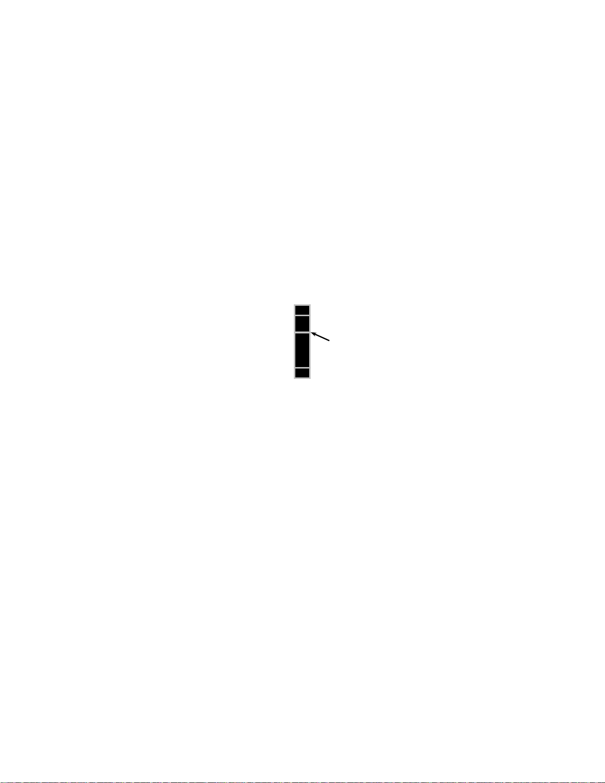
2.17 RETICLE INTENSITY (RETINT)
Activating the RETINT menu item allows the operator to
adjust the color of the boresight reticle from white, through
the gray scale to black, to provide the best contrast with the
viewed image.
Once activated, the reticle intensity scale is presented in the
eyepiece display as shown in Figure 2-8.
Figure 2-8. Reticle Intensity Control.
Reticle intensity is adjusted by pressing the UP / DOWN
buttons to move the status bar along the + / - scale.
Repeatedly pressing the UP / DOWN buttons will move the
status bar in single increments. Pressing and holding the
UP / DOWN buttons will auto-scroll the status bar in multiple
increments.
If the UP / DOWN buttons are not pressed within 3 seconds,
the reticle intensity scale will disappear and the CNVD-T2
will revert to normal viewing mode.
2-17
Page 40

2.18 RETICLE (RET)
Activating the RET menu item allows for repositioning the
boresight reticle and toggling it on or off.
Once selected, the sub-menu shown in Figure 2-9 will
appear in the eyepiece display. If in ZOOM 2X mode, P2X
will be displayed in lieu of POS.
EXIT POS OFF
Figure 2-9. Menu - Reticle Sub-Menu.
EXIT Sub-Menu Item
Activating the EXIT sub-menu item returns the display to the
Main Menu.
POS (or P2X) Sub-Menu Item
Activating the POS (or P2X) sub-menu item allows for
adjusting the position of the reticle in the eyepiece display.
• Adjustments are made using the UP / DOWN / LEFT
/ RIGHT buttons. When adjusting reticle position,
AZ (azimuth) and EL (elevation) values appear in
the eyepiece display as shown in Figure 2-10. The
numbers represent “clicks” of the reticle. Azimuth
and elevation values can rapidly be returned to 0 by
pressing the UP and DOWN buttons or the LEFT
and RIGHT buttons simultaneously.
• When in ZOOM 1X mode, the reticle moves in
2-pixel increments each time the UP / DOWN / LEFT
/ RIGHT buttons are pressed. The reticle is moved
in 1-pixel increments when in ZOOM 2 X mode. See
section 2.23 for click equivalents and zeroing
information.
2-18
Page 41

2.18 RETICLE (RET) (Continued)
POS ADJ
AZ 8 L
EL 2 U
Figure 2-10. Reticle Position Adjustment.
OFF Sub-Menu Item
Activating the OFF sub-menu item turns the boresight reticle
off. Turning the reticle back on is accomplished by selecting
the RET menu item from the Main Menu.
2.19 PICTURE (PIC)
Activating the PIC menu item takes a digital picture of the
viewed image. The image is automatically stored to nonremovable flash memory with a maximum capacity of
approximately 150 pictures.
When attempting to take more than the maximum allowable
number of pictures, the words “CAMERA FULL” will appear
in the eyepiece display. No more pictures may be taken until
one or more of the stored pictures are deleted (see
section 2.20.).
Images stored in the CNVD-T2 may be downloaded to the
Image Adapter Cable for further transfer to a personal
computer (see Section V).
2-19
Page 42

2.20 REVIEW (REV)
Activating the REV menu item allows for review of stored
pictures. Pressing the UP / DOWN butt ons bri ngs up the
next / previous stored picture, respectively.
While in review picture mode, pressing the MENU / ZOOM
button again calls up the Review Sub-Menu shown below.
KEEP
DELETE
DELETE ALL!
EXIT
Figure 2-11. Menu – Review Sub-Menu.
• Activating the KEEP sub-menu item returns the
display to the review picture mode.
• Activating the DELETE sub-menu item permanently
removes the selected picture from flash memory and
returns the display to the review picture mode.
• Activating the DELETE ALL! sub-menu item
permanently removes all stored pictures from flash
memory and returns the display to normal viewing
mode.
• Activating the EXIT sub-menu item returns the
display to normal viewing mode.
NOTE
The CNVD-T2 does not “remember” the polarit y or
zoom settings in place at the time a picture was
taken. When reviewing stored images through the
eyepiece display, they will appear with polari ty and
zoom characteristics that correspond to the
CNVD-T2 settings in place at the time they are
being reviewed.
2-20
Page 43

2.21 RS170 / VGA
Activating the RS170 / VGA menu item toggles between
these two display formats. VGA format is appropriate for
high-motion viewing. RS170 format is appropriate for all
other applications. See Section V for instructions on how to
connect the CNVD-T2 to an external monitor for viewing live
thermal imagery.
NOTE
When viewing the CNVD-T2 thermal image on an
external monitor, the RS170 video format must be
selected. Using the VGA video format for this
purpose will result in an extremely distorted image.
2.22 EXIT
Exiting the Main Menu is accomplished by either activating
the EXIT menu i tem or pressing the LEFT or RIGHT button.
Exiting the Main Menu saves all changes made and returns
the CNVD-T2 to normal viewing mode.
NOTE
The message “NO SAVE” will appear at the
bottom of the display if settings could not be saved
due to low battery power. Changes will be made,
but not saved for future use.
2-21
Page 44

SECTION IV
10m
25m
100m
150m
300m
ZOOM 1X
0.3cm
0.7cm
2.6cm
3.9cm
7.9cm
ZOOM 2X
0.1cm
0.4cm
1.3cm
2.0cm
3.9cm
ALIGNMENT / ZEROING
2.23 ALIGNMENT / ZEROING PROCEDURES Clip-On
WARNING
Activating Z OOM 2X when the CNVD-T2 is used
in-line with other optical sights may introduce an
error in the aiming function of those devices.
When being used in-line with an optical sight, the CNVD-T2
should be placed in ZOOM 1X, the boresight reticle should
be turned off, and zeroing procedures associated with the
primary sight should be used. Placing the CNVD-T2 in front
of an already zeroed optic / weapon combination does not
necessitate rezeroing.
Stand-Alone
Each click of the CNVD-T2 reticle moves the shot group
about 0.7cm at 25m (when in ZOOM 1X). Othe r click
equivalents are provided in Table 2-1. Changing the position
of the boresight reticle corresponds to a subsequent change
in shot group movement (i.e., the UP button will move the
strike of the round up).
Table 2-1. Reticle Adjustments.
Single Click Equivalents
2-22
Page 45
5.2cm
2.23 ALIGNMENT / ZEROING PROCEDURES
(Continued)
When being used as a stand-alone device, the example
below shows how to align the CNVD-T2 to be parallel with
the rail of the host weapon on a 25-meter range. This
“infinite parallel” configuration is appropriate for many
mission profiles. Once parallel, the CNVD-T2 / weapon
combination may be zeroed in accordance with established
unit, departmental, or agency procedures.
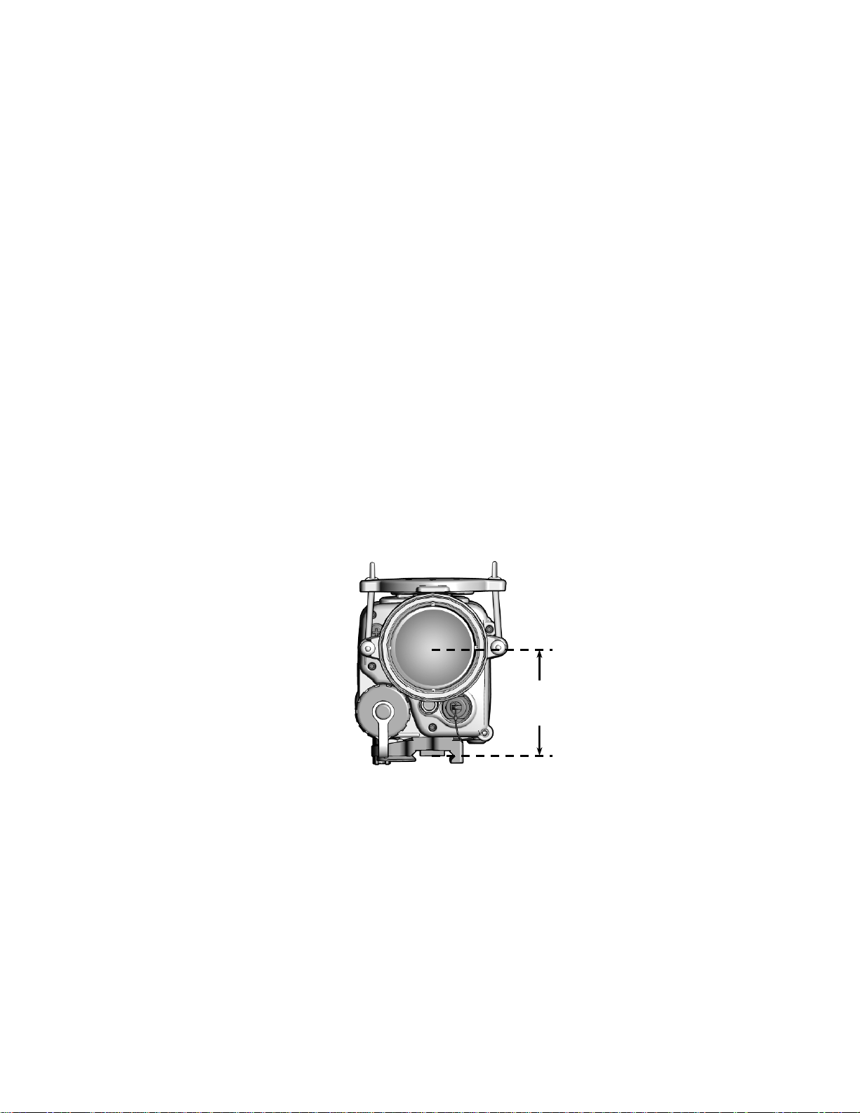
1. Once mounted to a weapon, the distance from the top of
the rail to the centerline of the CNVD-T2 objective lens is
5.2cm. Calculate the designated strike point by adding
this value to the distance from the center of the weapon
barrel to the top of the weapon rail (3.1cm for an
M4/M4A1). Therefore, in this example, the designated
strike point is 5.2cm + 3.1cm = 8.3cm down from the
center of the target.
Figure 2-12. Strike Point Calculation.
2-23
Page 46
2.23 ALIGNMENT / ZEROING PROCEDURES
(Continued)
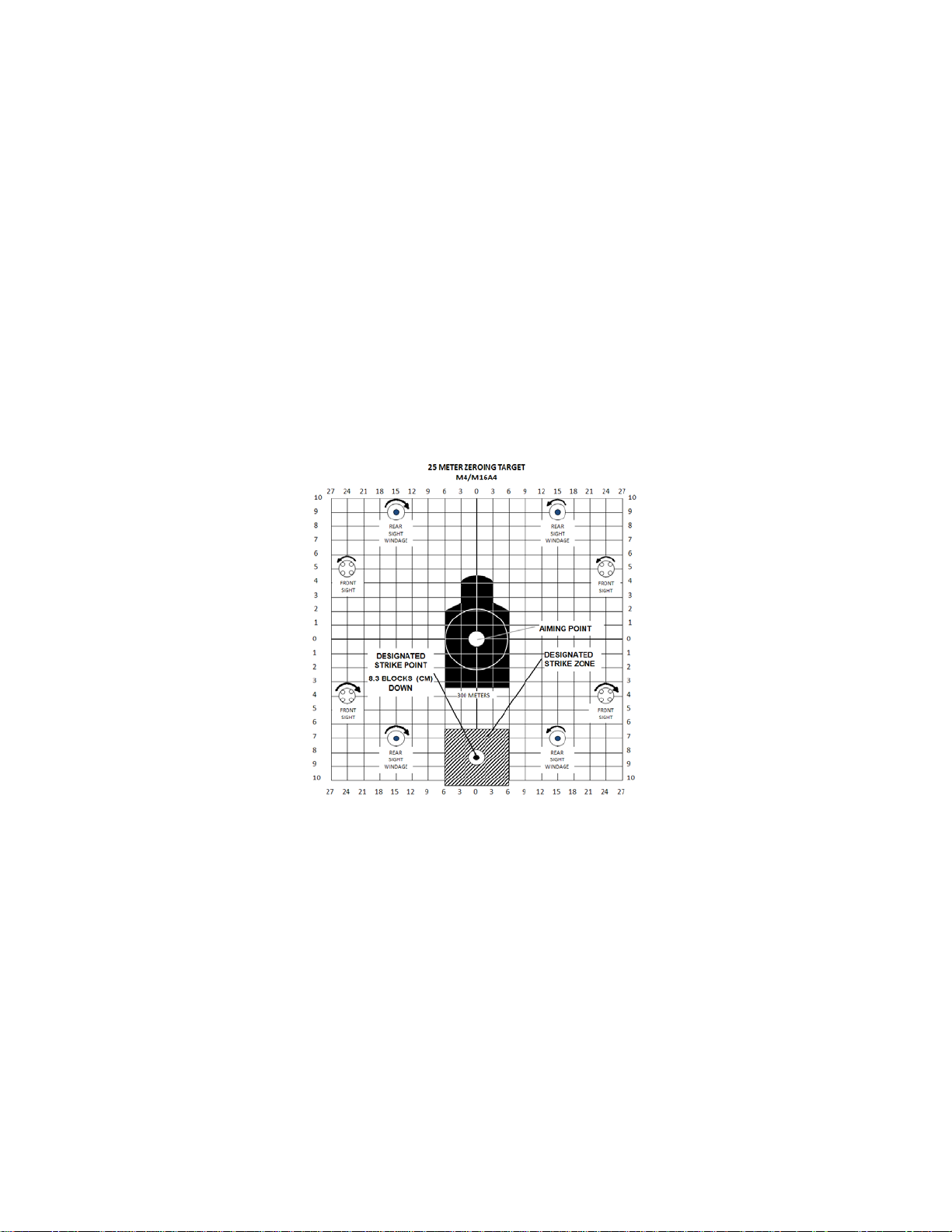
2. Mark the designated strike point on a standard 25-meter
zeroing target.
3. Draw a designated strike zone around the strike point that
corresponds in size to an acceptable level of desired
accuracy.
2-24
Figure 2-13. Designated Strike Zone.
Page 47

2.23 ALIGNMENT / ZEROING PROCEDURES
(Continued)
4. Mount the target on an “E” silhouette or other suitable
surface at 25 meters.
5. Mount the CNVD-T2 to the weapon.
6. Turn on the CNVD-T2 using the startup procedures in
section 2.11.
7. Turn the boresight reticle on via the system menu and
align the reticle with the center of the target per section
section 2.18.
8. Fire a 3-round shot group and note the center of the shot
group relative to the designated strike point.
9. Adjust the position of the reticle to move the center of the
shot group to the designated strike point.
10. Fire another 3-round shot group and again observe the
center of the new shot group relative to the designated
strike point.
11. When 2 out of 3 rounds are in the designated strike
zone, the CNVD-T2 is aligned with the rail of the host
weapon.
2-25
Page 48
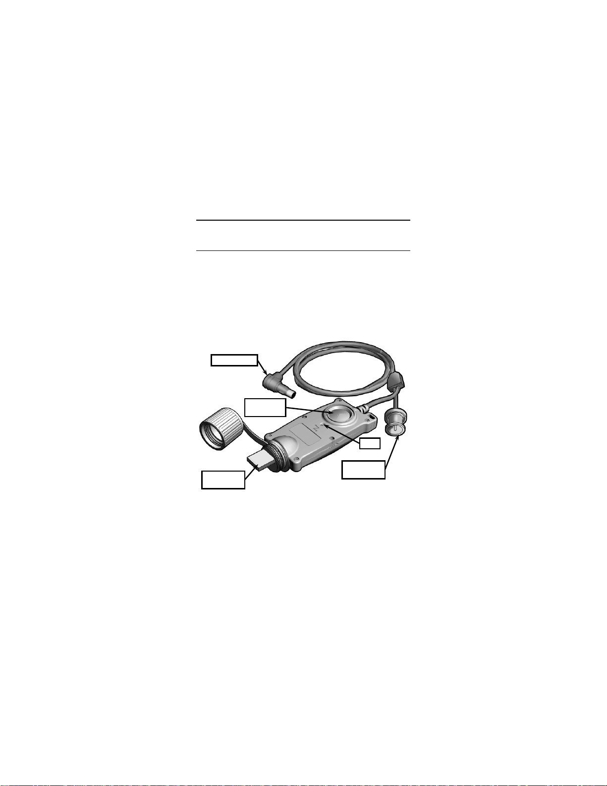
IMAGE DOWNLOAD / VIEWING
LED
DOWNLOAD
BUTTON
USB
CONNECTOR
CABLE PLUG
CONNECTOR
SECTION V
2.24 IMAGE ADAPTER CABLE
The Image Adapter Cable is used to connect the CNVD-T2
to an external monitor for viewing live thermal imagery; or to
connect to a PC so that captured thermal images may be
retrieved for download. The Image Adapter Cable is shown
in Figure 2-14.
2-26
BNC
Figure 2-14. Image Adapter Cable.
Page 49

2.25 VIEWING LIVE IMAGERY
Viewing live thermal imagery from the CNVD-T2 on an
external monitor is accomplished as follows:
1. Remove the video jack plug (captive to the CNVD-T2)
from the video jack.
2. Plug the Image Adapter Cable into the CNVD-T2 by
aligning the white dot on the cable plug with the white dot
on the video jack. Push the cable plug into the video jack
until it locks into pla ce.
3. Attach the BNC connector to an external monitor or
television.
4. Follow the CNVD-T2 startup procedures contained in
section 2.11 and ensure RS170 video format is selected
from the Main Menu as described in section 2.21.
5. Follow instructions provided by the manufacturer of the
monitor or television for viewing video from an external
device.
CAUTION
When the cable plug is inserted into the video
jack, it automatically locks in place. To remove i t,
pull straight back on the cable plug. Do not
remove the cable plug by pulling on the cable
itself.
2-27
Page 50

2.26 RETRIEVING STORED IMAGES
Images stored in the CNVD-T2 may be downloaded to the
Image Adapter Cable and converted to either a .tiff or .jpeg
file format (depending on model). Once downloaded,
images may then be viewed, saved, edited, and/or deleted
by a PC in the same manner as any files accessed through
an external drive. The Image Adapter Cable can store in
excess of 400 .tiff files. Storage capacity for .jpeg files is
considerably higher.
NOTE
The download process does not remove any of the
raw images from the CNVD-T2’s flash memory.
Deleting saved pictures from the CNVD-T2 m ust
be accomplished as described in section 2.20.
1. Remove the video jack plug (captive to the CNVD-T2)
from the video jack.
2. Plug the Image Adapter Cable into the CNVD-T2 by
aligning the white dot on the cable plug with the white dot
on the video jack. Push the cable plug into the video jack
until it locks into place.
3. Insert the Image Adapter Cable’s USB connector into a
free USB port on the computer. The PC will recognize
the Image Adapter Cable as an external hard drive and
will normally open a Windows Explorer dialogue box to
display the contents of the drive.
4. Wait for the LED on the Image Adapter Cable to turn solid
green. Other LED status indicators are described in
Table 2-2.
2-28
Page 51

LED Indicator
Status Condition
Green (steady)
Powered and passed self test
Green flashing
Data transfer in progress
Red (steady)
Powered but failed self test
Red flashing
Operational error
2.26 RETRIEVING STORED IMAGES (Continued)
5. Press the Download Button. This downloads all images
stored in the CNVD-T2’s flash memory, converts them to
.tiff (or .jpeg) format, and saves them to the f lash memory
of the Image Adapter Cable. The LED on the Image
Adapter Cable will flash green during this process.
NOTE
The Image Adapter Cable creates a separate
folder for each of the devices it has been
connected to. Initiating the download process
from the same device will cause the Image
Adapter Cable to overwrite the existing folder.
Renaming the old folder prior to downloading new
images will preserve the content of the original
folder.
6. Wait for the LED on the Image Adapter Cable to return to
a steady green state indicating that the transfer process is
complete. Open or refresh the Windows Explorer
dialogue box to view the contents of the Image Adapter
Cable’s flash memory. Images may then be viewed,
saved, edited, and/or deleted in the same manner as any
files accessed through an external hard drive.
Table 2-2. Image Adapter LED Indicators.
2-29
Page 52

2-30
Page 53

Symptom
Malfunction
Corrective Action
1. No display is
a. CNVD-T2 is in Standby
a. Press any arrow button to
b. Software overload.
b. Cycle CNVD-T2 power
on/off (section 2.5).
c. Brightness setting too
c. Adjust brightness setting
d. Contrast setting
improperly adjusted.
d. Adjust contrast setting
(section 2.8).
e. Battery power is low or
e. Install fresh batteries
f. Battery compartment
requires cleaning.
f. Clean battery compartment
(section 3.2).
CHAPTER 3
MAINTENANCE AND SERVICING
MAINTENANCE AND TROUBLESHOOTING
3.1 TROUBLESHOOTING
The procedures below will help correct some of the basic
problems that may arise with the CNVD-T2. If the
equipment malfunction is not listed, or the actions listed do
not correct the fault, refer to section 3.4 for additional
guidance.
Table 3-1. Troubleshooting Proce dure s.
SECTION I
present upon
start-up.
Mode.
low.
batteries not properly
installed.
“wake” from Standby Mode
(section 2.5).
(section 2.7).
(section 2.2).
3-1
Page 54

3.1 TROUBLESHOOTING (Continued)
Symptom
Malfunction
Corrective Action
2. Poor or
a. Battery power is low.
a. Install fresh batteries
(section 2.2).
b. Not focused for viewing
distance being observed.
b. Focus objective lens
(section 2.9).
c. CNVD-T2 requires
c. Perform a calibration
d. Objective lens and/or
d. Remove night adaptive filter
(section 3.2).
e. Night adaptive filter /
e. Clean night adaptive filter /
3. Display is on
a. Objective lens cover
lens.
a. Flip up objectiv e lens cover
b. Not focused for viewing
distance being observed.
b. Focus objective lens
(section 2.9).
c. Brightness setting too
c. Adjust brightness setting
d. CNVD-T2 requires
calibration.
d. Perform a calibration
(section 2.16).
e. Contrast setting
e. Place CNVD-T2 in auto-
4. No reticle is
a. Brightness setting too
low.
a. Adjust brightness setting
(section 2.7).
b. Reticle is not turned on.
b. Turn reticle on
c. Reticle intensity set too
low.
c. Adjust reticle intensity
(section 2.17).
Table 3-1. Troubleshooting Procedures (Continued).
degraded image.
but no thermal
image is present.
visible.
3-2
calibration.
eyepiece obscured by dirt,
dust or grime.
demist shield scratched,
cracked, or obscured by
dirt, dust or grime.
installed over objective
low.
improperly adjusted.
(section 2.16).
/ demist shield; clean objective
lens and eyepiece
demist shield (section 3. 2) .
Replace if necessary.
(section 2.4).
(section 2.7).
gain mode (section 2.8).
(section 2.18).
Page 55

3.2 INSPECTION / CLEANING
WARNING
Isopropyl alcohol is flammable and toxic. To avoid
injury, keep away from open fire and use in a well
ventilated area.
The operator should inspect the CNVD-T2 bef ore each use
and after it has been in extreme conditions, such as
prolonged exposure to intense temperatures. The following
procedures will prolong the life of the CNVD-T2 and help
ensure safe operation.
CNVD-T2 Housing
Inspect the CNVD-T2 housing for any signs of damage
including cracks, missing parts, and any other visible
defects. To clean the housing, rinse with water and wipe
clean with a soft cloth. Clean around buttons and housing
details with a cotton swab.
Battery Compartment
Inspect the battery compartment for dirt, dust, or corrosion.
Dirt or debris that cannot be shaken loose from the battery
compartment may be removed using a cotton swab. If
necessary, clean battery contacts with a cotton swab and
isopropyl alcohol.
3-3
Page 56

3.2 INSPECTION / CLEANING (Continued)
Optical Surfaces
CAUTION
The coating on the night adaptive filter / demist
shield may be damaged if cleaned while wet.
Clean the night adaptive filter / demist s hield only
when dry and using the lens brush.
Inspect optical surfaces for dirt, dust, and grime. Remove
any large particles or loose dirt using the lens brush. Fine
cleaning of the optical surfaces should be performed using a
lens pen. Avoid using excessive force as this may result in
scratching the lenses. The night adaptive filter / demist
shield should be replaced if cracks are present or scratches
degrade performance.
Video Jack
Inspect the video jack for corrosion, dirt and damage. Gently
remove any large particles of foreign matter and clean the
contacts with a cotton swab dipped in isopropyl alcohol.
3-4
Page 57

3.3 CORRECTIVE MAINTENANCE
The CNVD-T2 has no internal parts or assemblies
replaceable by the user or organizational level personnel.
Refer to section 3.4 regarding maintenance and/or repair
actions beyond those described in this manual.
Throw-Lever Tension Adjustment
The throw-lever mounting bracket has a locknut that adjusts
the tension required to clamp it to the weapon rail. It is
preset at the factory but may need adjustment when initially
mounted to the rail of the host weapon. If adjustment is
required, the following procedures apply and are performed
with the CNVD-T2 removed from the host weapon:
CAUTION
Creating too much tension with the locknut may
result in damage to the mounting bracket when the
throw-lever is forced against the weapon rail.
Creating too little tension with the locknut may
allow for movement of the CNVD-T2 on the rail.
Never completely remove the locknut from the
mounting bracket.
1. Swing the throw-lever closed (against the body of the
CNVD-T2), then push in the lever lock to engage the
locking mechanism.
2. Using the provided 3/8” box wrench, adjust the locknut
using slight movements (2 or 3 degrees). Turning the
locknut counterclockwise will decrease tension on the
throw-lever. Turning it clockwise will increase tension on
the throw-lever.
3-5
Page 58
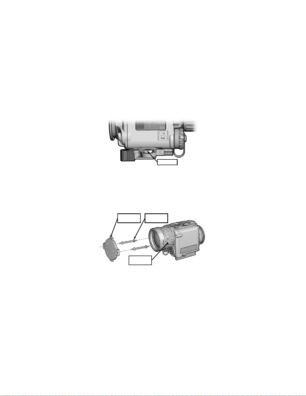
3.3 CORRECTIVE MAINTENANCE (Continued )
LOCKNUT
LENS COVER
OBJECTIVE
COLLAR
STRAP
Figure 3-1. Adjusting Throw-Lever Tension.
3. Test each adjustment by attempting to mount the
CNVD-T2 to the weapon rail per section 2.3.
Objective Lens Cover / Straps Replacement
1. Review Figure 3-2 to gain familiarity with components
referred to in this procedure.
OBJECTIVE
LENS COVER
Figure 3-2. Replacing Objective Lens Cover / Straps.
3-6
Page 59

3.3 CORRECTIVE MAINTENANCE (Continued )
2. Grasp the middle of one lens cover strap and pull it free
from the objective lens cover.
3. Repeat step 2 for the other lens cover strap.
4. With fingers, pull lens cover straps free from the eyelets
on the objective collar.
5. Moisten and thread replacement lens cover straps
through the eyelets on the objective collar and pull
through using fingers.
NOTE
Step 6 is performed with the flat side of the
objective lens cover facing out, away from the
objective lens.
6. Moisten and thread opposite end of the lens cover straps
through the eyelets on the objective lens cover and pull
through using fingers.
7. Flip the objective lens cover down and over the objective
lens.
3-7
Page 60
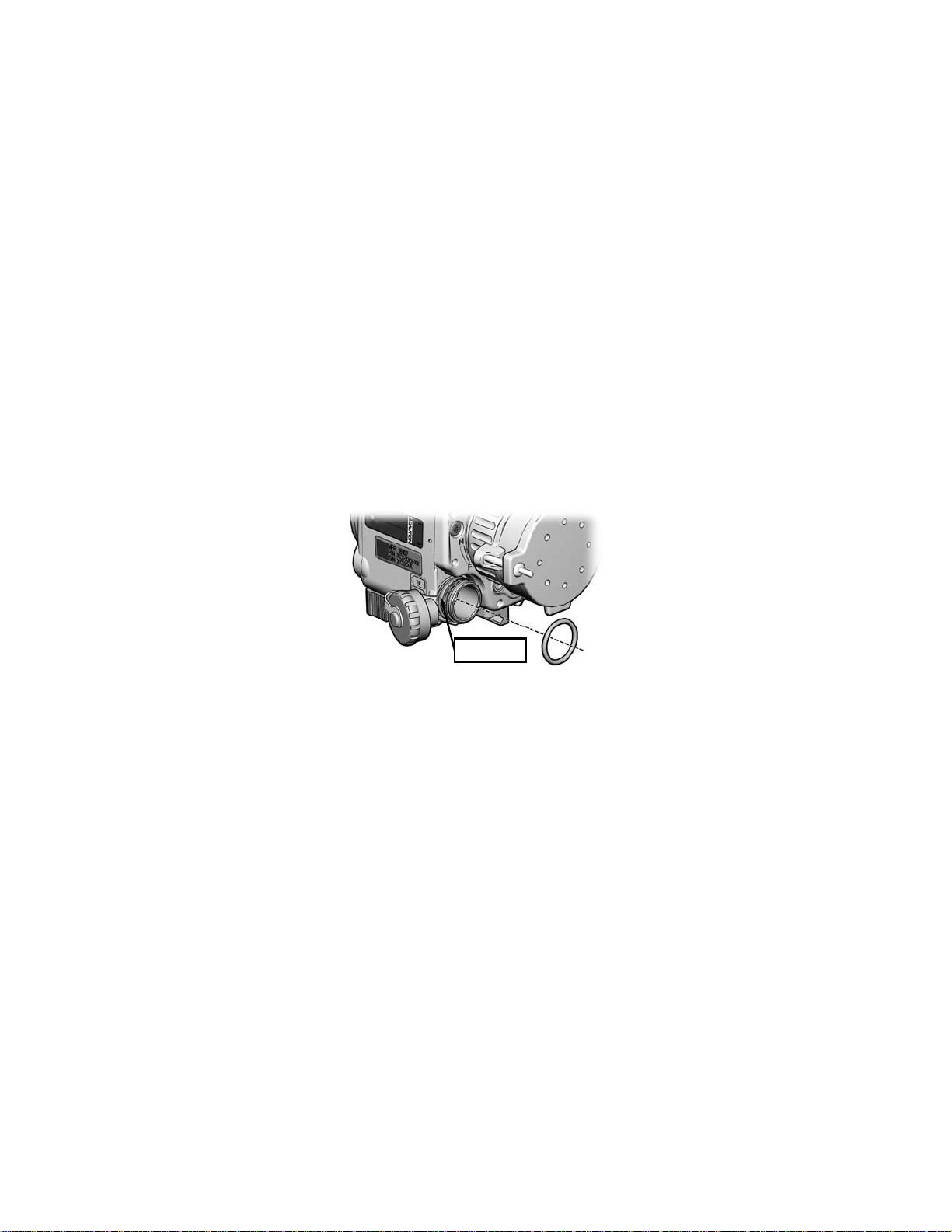
3.3 CORRECTIVE MAINTENANCE (Continued )
RETAINING
Battery Compartment O-Ring Replacement
1. Unscrew the battery cap until it comes free of the battery
compartment threads.
2. Use the fingers of one hand to squeeze the battery
compartment o-ring while simultaneously pushing it out of
its retaining groove (see Figure 3-3). Grasp the o-ring
with fingers of the other hand and pull it off the battery
compartment threads.
GROOVE
Figure 3-3. Batttery Compartment O-Ring.
3. Use a cotton swab dipped in isopropyl alcohol to clean
the o-ring retaining groove of any dirt, grease, or debris.
4. Apply a thin, even coat of fluorinated grease to the
replacement o-ring.
5. Stretch the replacement o-ring over the battery
compartment threads and slip it into its retaining groove.
6. Reinstall the battery cap and tighten.
3-8
Page 61
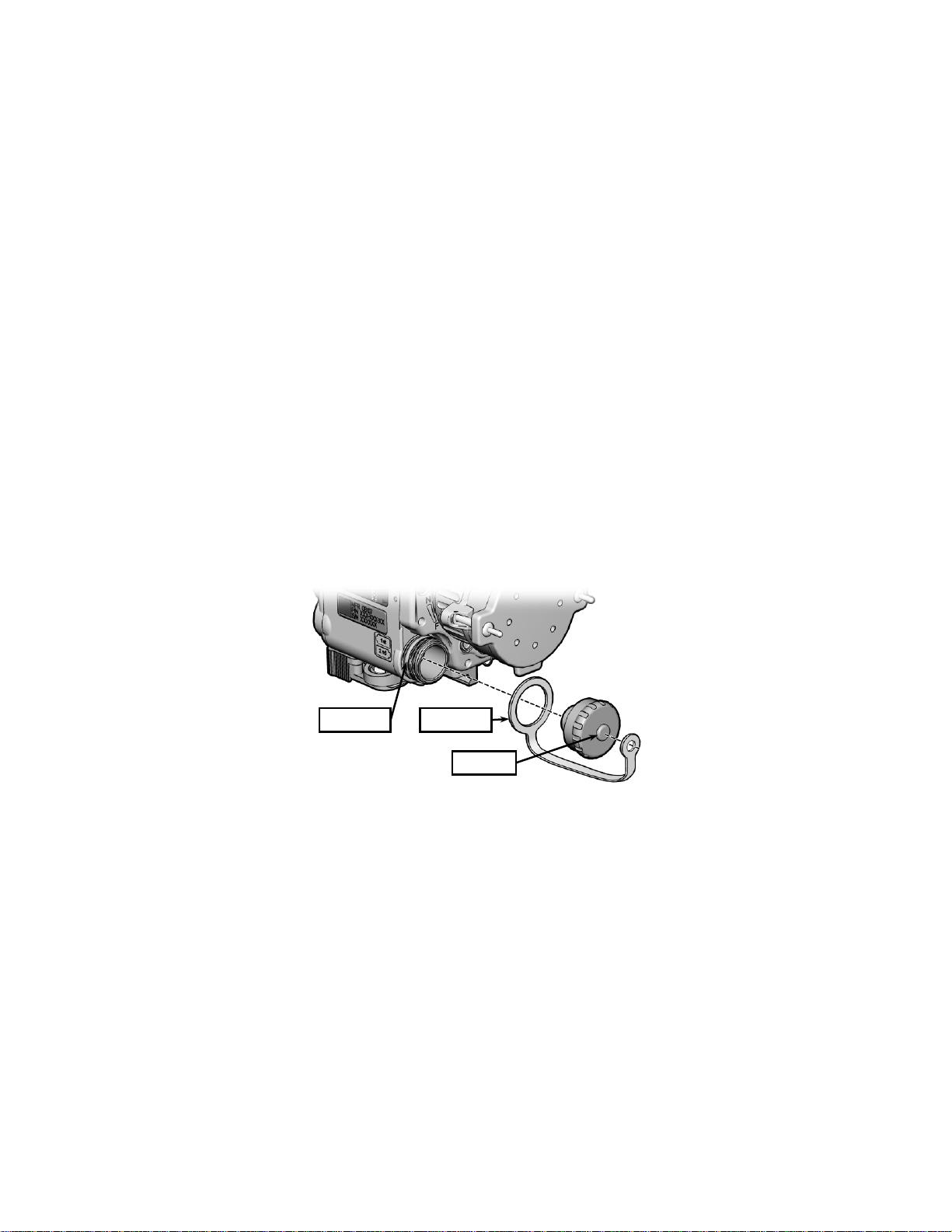
RETAINING
BATTERY CAP
CAP POST
3.3 CORRECTIVE MAINTENANCE (Continued )
Battery Cap / Battery Cap Lanyard Replacement
1. Turn the battery cap counterclockwise until it comes free
of the battery compartment threads.
2. Use the fingers of one hand to squeeze the battery
compartment o-ring while simultaneously pushing it out of
its retaining groove. Grasp the o-ring with fingers of the
other hand and pull it off the battery compartment
threads.
3. Simultaneously stretch and pull the larger eye of the
battery cap lanyard off the battery compartment threads.
4. Pull the smaller eye of the battery cap lanyard off the
battery cap post.
GROOVE
LANYARD
BATTERY
Figure 3-4. Battery Cap / Battery Cap Lanyard.
3-9
Page 62

3.3 CORRECTIVE MAINTENANCE (Continued )
5. Replace the battery cap and/or battery cap lanyard as
necessary.
6. Stretch smaller eye of the battery cap lanyard over the
post on the battery cap.
7. Simultaneously stretch and pull the larger eye of the
battery cap lanyard over the battery cap threads. Work
the lanyard until it is seated neatly in the groove closest to
the CNVD-T2 housing.
8. Stretch the o-ring over the battery compartment threads
and slip it into its retaining groove.
9. Reinstall the battery cap and tighten.
3-10
Page 63

SERVICE / PACKING AND UNPACKING
SECTION II
3.4 RETURN INSTRUCTIONS
3.4.1 For service, repair, or replacement, first e-mail
or call toll-free 1-877-744-4803.
3.4.2 To assist with determining if the item is repairable, the
following information shall be provided:
a. Serial number of the defective item;
b. Thorough description of the malfunction, defect, or
damage; and
c. If known, an explanation as to how the malfunction,
defect or damage occurred.
If the item is determined to be Beyond Economical Repair,
follow applicable replacement procedures through your
Property Officer. If it is determined that the item is under
warranty, or should be returned for repair, a Return Material
Authorization (RMA) number will be provided.
3.4.3 When returning the CNVD-T2 for service / repair, the
following procedures should be followed to prevent any
additional damage:
a. Be sure that the CNVD-T2 is free of all contaminants
such as dirt or any other foreign material.
b. Remove batteries.
c. Place the CNVD-T2 in the soft carrying case.
3-11
Page 64

3.4.4 Place the item and a copy of the test report or detailed
description of the failure in a suitable packing container.
Mark the package with “Field Return” and the RMA number.
Ship via fastest, traceable, pre-paid means to L-3 Insight
Technology Incorporated, 9 Akira Way, Londonderry, NH
03053.
3.5 WARRANTY INFORMATION
The CNVD-T2 is under warranty from defects in material and
workmanship for a minimum of one (1) year from the date of
manufacture. This warranty does not protect against
damage due to misuse, mishandling or battery leakage.
Additional warranty coverage may have been provided
through the contract or via subsequent contract extension.
Specific warranty terms can be obtained from your
procurement agent, Contracting Officer or L-3 Insight
Technology Incorporated.
3.6 NON-WARRAN TY INFORMATION
Non-warranty repairs are subject to an evaluation fee. The
item will be tested and evaluated for failure, then customer
permission and payment terms are obtained prior to any
repairs being performed.
3-12
Page 65

APPENDIX A
END ITEM COMPONENTS AND REPAIR PARTS
A.1 SCOPE
This Appendix lists end item components and repair parts
available for the CNVD-T2.
INTENTIONALLY LEFT BLANK
A-1
Page 66
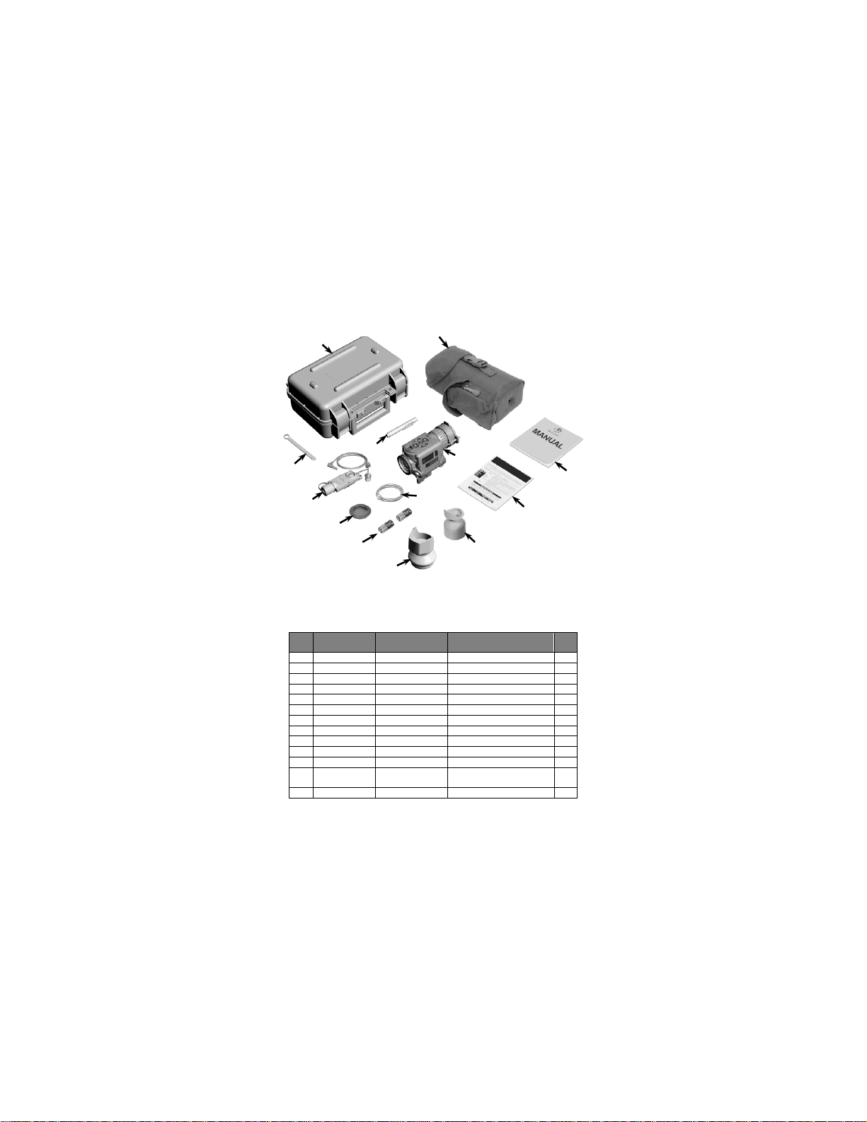
A.2 END ITEM COMPONENTS
ITEM
NO.
NATIONAL
STOCK NUMBER
PART
NUMBER
1
TBD
CQT-060-A2
Transit / Storage Case
1
2
8105-01-579-5864
ITI-501-02
Soft Carrying Case
1
3
7610-01-579-5672
CQT-TM-ITI
Operator Manual
1
4
7610-01-582-1707
CQT-QRG-ITI
Quick Reference Guide
1
5
5855-01-579-5688
CQB-670-02
Eyecup 1 6
5855-01-561-8116
CQB-630-02
Interface Hood
1 7 6135-01-559-9641
DL123ABK
Battery, 3V, Lithium
2 8 5855-01-579-5695
CQB-506-A2
Filter, NV Spectrum
1
9
5855-01-579-5690
WTM-030-A1
Image Adapter Cable (.tiff)
1
10
5120-01-582-2832
ITI-150
Box Wrench, 3/8”
1
11
5855-01-579-5680
ITI-678
Lens Pen
1
CNVD-T2 Assembly (see Figure
13
5855-01-579-9859
CQT-381
Neck Cord
1
1 2 8 3 9
10
6
12
11
13
Figure A-1. End Item Components.
Table A-1. List of End Item Components.
12 N/A CQT-052-A2
A-2
A-2 for parts breakdown)
4
5 7
DESCRIPTION QTY
1
 Loading...