

EOTech CNVD-T3 User Manual
CT3-TM-ITI
OPERATOR MANUAL
FOR THE
Clip-On Night Vision Device – Thermal 3
(CNVD-T3)
Rev. 2 22 December 2011


SAFETY SUMMARY
1. GENERAL SAFETY INSTRUCTIONS
This manual contains operating instructions and
maintenance procedures which may cause injury or death to
personnel, or damage to equipment if not properly followed.
Prior to performing any task, the WARNINGs, CAUTIONs
and NOTEs included in that task shall be reviewed and
understood.
2. WARNINGS, CAUTIONS AND NOTES
Safety headings used in this manual and their respective
definitions are as follows:
WARNING..
Highlights an essential operating or maintenance
procedure, practice, condition or statement, which,
if not strictly observed, could result i n injury to, or
death of, personnel or long term health hazards.
CAUTION..
Highlights an essential operating or maintenance
procedure, practice, condition or statement, which,
if not strictly observed, could res ult in damage to,
or destruction of, equipment or loss of mission
effectiveness.
Highlights an essential operating or maintenance
procedure, condition or statement.
NOTE
i

3. SAFETY PRECAUTIONS
The following general safety precautions supplement the
specific WARNINGs, CAUTIONs and NOTEs that appear
elsewhere in this manual.
3.1
Batteries . The Clip-On Night Vision Device – Thermal 3
(CNVD-T3) is powered by two lithium DL123A batteries.
The following safety precautions apply when handling lithium
batteries:
• Do not short circuit, puncture, incinerate, or
disassemble.
• Do not att em pt to recharge.
• Prior to use, inspect all batteries for cracks, dents,
leakage, or bulging. Never install a defective battery
in the CNVD-T3.
WARNING..
Do not use the CNVD-T3 with a mix of old and new
batteries, or batteries of different brands.
WARNING..
Lithium batteries can explode or cause burns if
disassembled, shorted, recharged, exposed to
water, fire, or high temperatures (above 100°C or
212°F). Do not place loose batteries in a pocket
or other container containing metal objects. Do
not store batteries with hazardous or combustible
materials. Store in a cool, dry, ventilated area.
ii

WARNING..
Use of incorrect batteries poses a risk of fire or
explosion. Be aware that batteries do exist with
similar physical characteristics to the DL123A
battery, but with a different voltage and/ or polarity
path. Ensure that only 3V lithium batteries with a
raised positive (+) terminal are installed in the
CNVD-T3.
WARNING..
Use of off-brand batteries poses a risk of fire or
explosion. Ensure that only 3V lithium batteries
produced by well-known battery manufacturers
such as Duracell®, Rayovac®, or Panasonic® are
installed in the CNVD-T3. These batteries are
specifically designed for use in high perform ance,
high-drain devices, and contain built-in fault and
heat protection features.
CAUTION..
Do not ship or store t he CNVD-T3 with batteries
installed.
3.2
Weapons Safety
. The CNVD-T3 is designed to be used
with destructive weapon systems. Improper operation or
misuse of the CNVD-T3 with these weapon systems could
lead to personal injury or death of either the operator or other
persons within weapons range. Safe firearms handling
procedures must be practiced at all times.
iii

WARNING..
Remove the CNVD-T3 from the weapon before
inspecting, cleaning, or performing other
maintenance functions.
3.3
Operation and Maintenance
.
CAUTION..
Use of acetone or gun cleaning agents containing
perchloroethylene or methylene chloride may
permanently damage the CNVD-T3 system.
CAUTION..
Pointing the CNVD-T3 directly at the s un without
the lens cover installed (and closed) may
permanently damage the thermal assembly.
iv

TABLE OF CONTENTS
SAFETY SUMMARY ....................................................................... i
TABLE OF CONTENTS ................................................................. v
LIST OF FIGURES ....................................................................... vii
LIST OF TABLES ........................................................................ viii
CHAPTER 1 ...................................................................................... 1-1
INTRODUCTION ......................................................................... 1-1
SECTION I .............................................................................. 1-1
GENERAL INFORMATION ............................................... 1-1
1.1 SCOPE .................................................................. 1-1
1.2 MODEL NUMBER AND EQUIPMENT NAME ...... 1-1
1.3 MANUFACTURER ................................................ 1-2
1.4 PURPOSE OF EQUIPMENT ................................ 1-2
1.5. ABBREVIATIONS AND ACRONYMS ................. 1-2
SECTION II ............................................................................. 1-3
EQUIPMENT DESCRIPTION ........................................... 1-3
1.6 SYSTEM DESCRIPTION ...................................... 1-3
1.7 TECHNICAL SPECIFICATIONS .......................... 1-4
CHAPTER 2 ...................................................................................... 2-1
1.8 MAJOR COMPONENTS ....................................... 1-5
OPERATING INSTRUCTIONS ................................................... 2-1
SECTION I .............................................................................. 2-1
PREPARATION FOR USE AND INSTALLATION ............ 2-1
2.1 PREPARATION FOR USE ................................... 2-1
2.2 BATTERY HANDLING .......................................... 2-1
2.3 MOUNTING INSTRUCTIONS .............................. 2-3
2.4 OBJECTIVE LENS AND EYEPIECE .................... 2-5
SECTION II ............................................................................. 2-7
OPERATING PROCEDURES ........................................... 2-7
2.5 FEATURES AND CONTROLS ............................. 2-7
2.6 POWER ................................................................. 2-8
2.7 BUTTON FUNCTIONS ......................................... 2-9
2.8 SYSTEM RESET ................................................ 2-10
2.9 BRIGHTNESS ADJUSTMENT ........................... 2-10
2.10 GAIN ADJUSTMENT ........................................ 2-11
2.10 FOCUS ADJUSTMENT .................................... 2-12
2.12 STARTUP PROCEDURES ............................... 2-13
2.13 MENU FUNCTIONS ......................................... 2-14
v

TABLE OF CONTENTS (cont'd)
2.14 SHUTDOWN PROCEDURES .......................... 2-25
2.15 IMAGE DOWNLOAD / VIEWING ..................... 2-26
SECTION III .......................................................................... 2-30
ALIGNMENT / ZEROING ................................................ 2-30
CHAPTER 3 ...................................................................................... 3-1
APPENDIX A.................................................................................... A-1
2.16 ALIGNMENT / ZEROING PROCEDURES ....... 2-30
MAINTENANCE AND SERVICING ............................................ 3-1
SECTION I .............................................................................. 3-1
MAINTENANCE AND TROUBLESHOOTING .................. 3-1
3.1 MAINTENANCE PROCEDURES ......................... 3-1
3.2 TROUBLESHOOTING PROCEDURES ............... 3-2
3.3 CORRECTIVE MAINTENANCE ........................... 3-5
SECTION II ........................................................................... 3-10
SERVICE / PACKING AND UNPACKING ...................... 3-10
3.4 RETURN INSTRUCTIONS ................................. 3-10
3.5 WARRA NT Y INFORMA T ION ............................. 3-11
3.6 NON-WAR RANTY INFOR MAT ION .................... 3-11
REPAIR PARTS / ACCESSORIES ........................................... A-1
A.1 Scope ................................................................... A-1
vi

LIST OF FIGURES
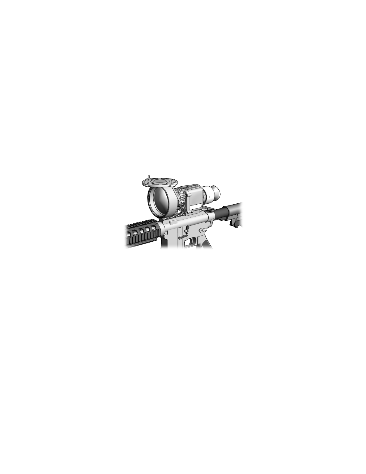
Figure 1-1 CNVD-T3 Mounted to M4 ............................................... 1-1
Figure 1-2 CNVD-T3 Major Components
Figure 2-1 Battery Installation
Figure 2-2 Throw-Lever Mounting Bracket
Figure 2-3 CNVD-T3 Mounted with ACOG®
Figure 2-4 CNVD-T3 Features and Controls
Figure 2-5 CNVD-T3 Features and Controls (cont’d)
Figure 2-6 Brightness Control
Figure 2-7 Gain Control
Figure 2-8 Main Menu
Figure 2-9 Menu – ZOOM 1X / ZOOM 2X
Figure 2-10 Menu – WHOT / BHOT
Figure 2-11 Menu – Calibration (CAL)
Figure 2-12 Menu – Reticle Intensity (RETINT)
Figure 2-13 Reticle Intensity Control
Figure 2-14 Menu – Reticle (RET) Control
Figure 2-15 Menu – Reticle Sub-Menu
Figure 2-16 Reticle Position Adjustment
Figure 2-17 Menu – Picture (PIC)
Figure 2-18 Menu – Review (REV)
Figure 2-19 Menu – Review Sub-Menu
Figure 2-20 Menu – MCAL / ACAL
Figure 2-21 Menu – RS170 / VGA
Figure 2-22 Menu – HAND / CLIPON
Figure 2-23 Menu - Exit
Figure 2-24 Image Adapter Cable
Figure 2-25 Strike Point Calculation
Figure 2-26 Designated Strike Zone
Figure 3-1 Rear Purge Screw
Figure 3-2 Adjusting Throw-Lever Tension
Figure 3-3 Replacing Objective Lens Cover
Figure 3-4 Replacing Objective Lens Protective Ring
........................................ 1-5
.......................................................... 2-2
...................................... 2-3
................................... 2-5
................................... 2-7
...................... 2-8
........................................................ 2-10
................................................................. 2-11
.................................................................... 2-14
..................................... 2-15
.............................................. 2-16
........................................... 2-17
............................ 2-17
............................................. 2-18
.................................... 2-18
.......................................... 2-19
....................................... 2-19
.................................................. 2-20
................................................ 2-21
......................................... 2-21
................................................ 2-22
................................................. 2-23
............................................ 2-24
................................................................. 2-25
................................................. 2-26
.............................................. 2-31
.............................................. 2-32
.......................................................... 3-3
..................................... 3-5
.................................... 3-6
..................... 3-7
vii

Table 1-1 Technical Specifications .................................................. 1-4
Table 1-2 List of Major Components
Table 2-1 LED Status Indicators
Table 2-2 Reticle Adjustments
Table A-1 Repair Parts / Accessories
LIST OF TABLES
............................................... 1-5
.................................................... 2-29
....................................................... 2-30
............................................. A-1
viii
CHAPTER 1
INTRODUCTION
SECTION I
GENERAL INFORMATION
Figure 1-1 CNVD-T3 Mounted to M4
1.1 SCOPE
This manual is intended for use by operators of the Clip-On
Night Vision Device - Thermal 3 (CNVD-T3). It provides a
system description, operational procedures, and
maintenance responsibilities. Complete familiarization with
this manual prior to using the equipment will ensure safe
operation and maximum effectiveness of the CNVD-T3.
1.2 MODEL NUMBER AND EQUIPMENT NAME
This manual applies to the following CNVD-T3 models:
a. CT3-002-A3, CNVD-T3, Tan, 6V
b. CT3-002-A6, CNVD-T3, Black, 6V
1-1

1.3 MANUFACTURER
ACOG®
Advanced Combat Optical Gunsight
C
Celsius
cm
Centimeter
F
Fahrenheit
ITAR
International Traffic in Arms Regulations
kg
Kilogram
LED
Light Emitting Diode
NSN
National Stock Number
PC
Personal Computer
RMA
Return Material Authorization
USB
Universal Serial Bus
L-3 Communications Corporation
Warrior Systems Division
Insight Operations
9 Akira Way
Londonderry, NH 03053 USA
1.4 PURPOSE OF EQUIPMENT
The CNVD-T3 is a battery operated, weapon-mounted,
thermal imaging device with an integrated digital camera. It
may be used in conjunction with other optic al sights, or as a
handheld unit. It allows for observation, target identification,
and target acquisition during the day or in adverse conditions
such as light rain or snow, dry smoke, and low light to total
darkness.
1.5. ABBREVIATIONS AND ACRONYMS
Abbreviations and acronyms used in this manual are listed
as follows:
CNVD-T3 Clip-On Night Vision Device – Thermal 3
m Meter
V Volt
1-2

EQUIPMENT DESCRIPTION
SECTION II
1.6 SYSTEM DESCRIPTION
The CNVD-T3 is a battery operated, weapon-mounted,
thermal imaging device with an integrated digital camera. It
may be used as a handheld device, mounted to a weapon in
a stand-alone configuration, or used in-line with a magnified
day optic.
The thermal imaging capability of the CNVD-T3 allows for
observation and target identification under adverse
conditions such as light rain or snow, dry smoke, and low
light to total darkness. It has a self-contained, internal
shutter used for calibration. The unit will not allow the user
to see through glass, water, or heavy rain / snow.
With the integrated digital camera, the CNVD-T3 allows for
acquisition, storage, and recall of viewed thermal images.
Thermal images may also be transferred to a personal
computer (PC) using the Image Adapter Cable.
The CNVD-T3 can be mounted to weapons equi pped with a
MIL-STD-1913 rail.
It is a ruggedized system designed for operation in battlefield
environments.
1-3

1.7 TECHNICAL SPECIFICATIONS
WEIGHT AND DIMENSIONS
Weight
(without batteries)
Length
7.0 inches (17.8 cm)
Width
4.6 inches (11.7 cm)
Height
4.4 inches (11.2 cm)
POWER
* Battery Life
> 4.5 hours
Startup Time
< 6 seconds
OTHER PARAMETERS
Field of View
6° diagonal (±4%)
Operating
Temperatures
Storage
Temperatures
Immersion
66 feet for 2 hours
Table 1-1 Technical Specifications
< 37.25 ounces (1.2 kg)
Batteries 2 DL123A lithium batteries
-26°F (-32°C) to +122°F (+50°C)
-40°F (-40°C) to +160°F (+71°C)
* Performance will vary depending on environmental conditions.
1-4
Major
Component
or in adverse conditions.
1
2
4
5
7
9
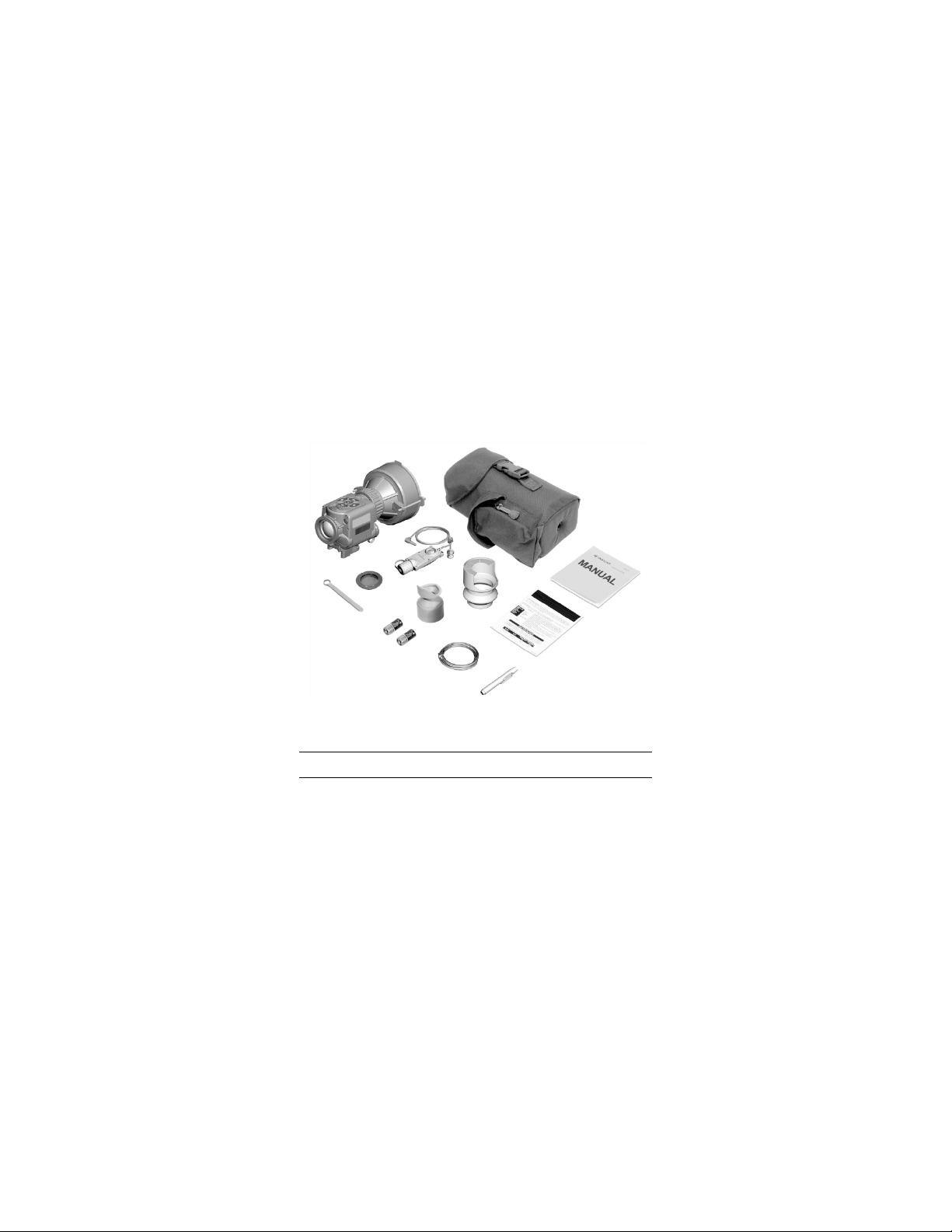
1.8 MAJOR COMPONENTS
The CNVD-T3 system includes the components shown in
Figure 1-2. Table 1-2 provides a brief functional description
of each item. The “Key” column in Table 1-2 corresponds to
the label numbers in Figure 1-2.
10
11
8
12
6
Figure 1-2 CNVD-T3 Major Components
Key
1
Table 1-2 List of Maj or Components
CNVD-T3
Assembly
A thermal imaging device used for
observation, target identification, and
passive target acquisition during the day
3
Function
1-5

Table 1-2 List of Major Components (cont’d)
Major
Component
3
Operator Manual
Provides detailed ope rating and
4
Quick Reference
Guide
Provides at-a-glance op era ti n g
procedures for the CNVD-T3.
5
Lens Pen
Used to clean the optical lenses of the
CNVD-T3.
6
against dropping or losing the device.
DL123A
power the CNVD-T3.
lever mounting bracket.
9
Night Adaptive
When attached, prevents fogging of the
environments.
10
Image Adapter
Used to connect the CNVD-T3 to an
viewed or downloaded.
Key
2
Soft Carrying
Case
Protects the CNVD-T3 and accessories
while in a field environment.
maintenance instructions specific to the
CNVD-T3.
Function
Neck Cord When attached to the CNVD-T3 and
7
Batteries,
8
Box Wrench, 3/8”
Filter / Demist
Shield
Cable
worn around the neck, helps guard
Two 3-volt DL123A batteries used to
Used to adjust the tension of the throw-
eyepiece and reduc es backlighting and
loss of night vision in low light
external monitor for viewing live
imagery, or to connect to a PC so that
captured thermal images may be
1-6

Major
Component
12
Eyecup,
When attached, reduces emission of
Table 1-2 List of Major Components (cont’d)
Key
11
Interface Hood Used to improve light security and
image quality when the CNVD-T3 is
mounted in-line with other optical sights.
Function
Removable
stray light from the eyepiece.
1-7

1-8

CHAPTER 2
OPERATING INSTRUCTIONS
PREPARATION FOR USE AND INSTALLATION
2.1 PREPARATION FOR USE
2.1.1
Unpacking the Equipment . Before unpacking the
equipment, verify that all major components listed in Table
1—2 are present. Check the CNVD-T3 assembly to ensure
the following additional items are also included:
a. Battery Cap Assembly
b. Video Jack Plug
c. Object i ve Lens Cover (and straps)
d. Objective Lens Protective Ring
If any of the major components or items listed above are
missing, seek guidance from the equipment issuing
authority.
2.1.2
Inspection of the Equipment
pieces of equipment for any damage such as cracks, loose
parts, faulty cables, or other visible defects. If any damage
or defects are noted, seek guidance from the equipment
issuing authority.
2.2 BATTERY HANDLING
2.2.1
Battery Inspection
batteries for any cracks, dents, leakage, or bulging. Never
install a defective battery in the CNVD-T3.
SECTION I
. Before use, inspect all
. Before installation, inspect the
2-1
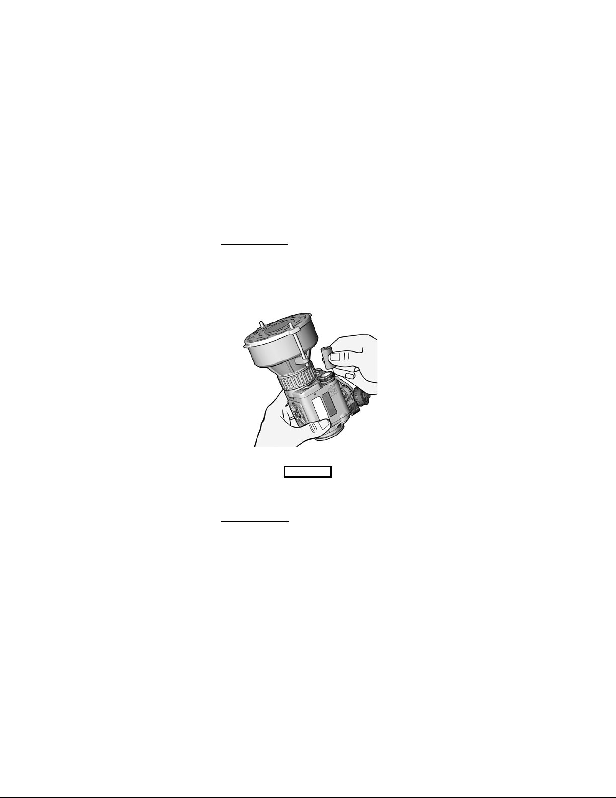
2.2.2 Battery Installation
. Proper battery orientation is
clearly marked on the CNVD-T3 housing. Unscrew the
battery cap and install the first DL123A lithium battery. Tilt
the CNVD-T3 to allow the battery to slide into the battery
compartment, thereby providing space to insert the second
battery. Install the second battery, then replace and screw in
the battery cap.
Figure 2-1 Battery Installation
CAUTION..
Do not ship or store the CNVD-T3 with batteries
installed.
2.2.3
Low Battery Power. A low battery message will
appear in the eyepiece display when approximately 20
minutes of continuous operation remain. If the batteries are
not replaced promptly when the “LOW P OWER” message
appears, the display quality will deteriorate rapidly.
2-2
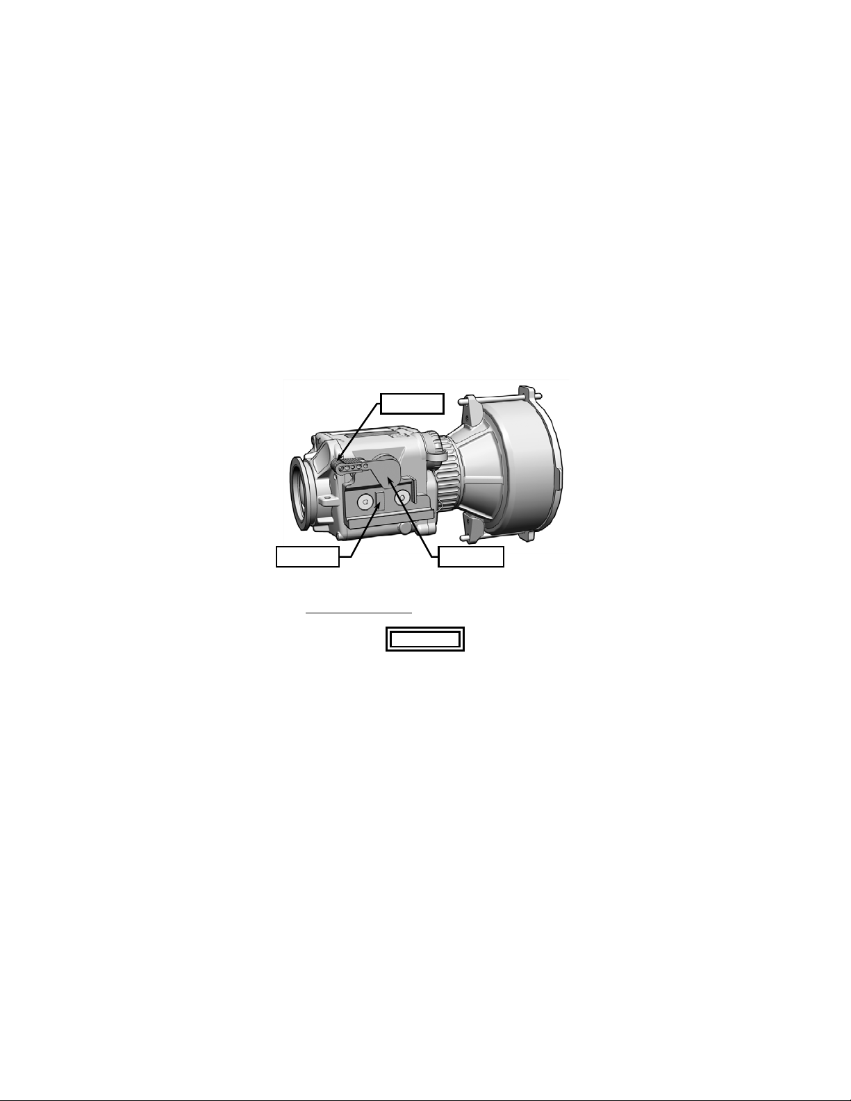
2.3 MOUNTING INSTRUCTIONS
The CNVD-T3 is equipped with a throw-lever mounting
bracket that is designed for direct attachment to weapons
with a MIL-STD-1913 rail.
Lever Lock
Recoil Lug Throw-Lever
Figure 2-2 Throw-Lever Mounting Bracket
2.3.1
Mounting Procedures
.
WARNING..
Be sure the weapon is CLEAR and SAFE before
proceeding.
NOTE
The CNVD-T3 may be placed at any position
(forward and aft) on the rail that is most
convenient for the operator. If, however, the
CNVD-T3 is removed from the rail, the operator
2-3
 Loading...