

Endress+Hauser Proline Promass 80S, Proline Promass 83S Technical Information

Products Solutions Services
TI00076D/06/EN/13.15
71231024
Technical Information
Proline Promass 80S, 83S
Coriolis flowmeter
Easy-to-clean flowmeter with self-drainable single-tube system & extended
transmitter functionality
Application
• Measuring principle operates independently of physical fluid
properties such as viscosity or density
• Dedicated for applications requiring optimal cleanability
under hygienic conditions
Device properties
• Large range of hygienic process connections
• 3A and EHEDG conform
• Fast recovery from CIP/SIP
• Device in compact or remote version
Promass 83
• 4-line backlit display with touch control
• HART, PROFIBUS PA/DP, Modbus RS485, FF, EtherNet/IP
Your benefits
• Reduced installation costs – fully self-drainable tube design
enables compact horizontal mounting
• Fewer process measuring points – multivariable
measurement (flow, density, temperature)
• Space-saving installation – no in/outlet run needs
Promass 83
• Quality – software for filling & dosing, density &
concentration, advanced diagnostics
• Flexible data transfer options – numerous communication
types
• Automatic recovery of data for servicing

Proline Promass 80S, 83S
2 Endress+Hauser
Table of contents
Function and system design . . . . . . . . . . . . . . . . . . . . . .3
Measuring principle . . . . . . . . . . . . . . . . . . . . . . . . . . . . . . . . . . . 3
Measuring system . . . . . . . . . . . . . . . . . . . . . . . . . . . . . . . . . . . . . 4
Input . . . . . . . . . . . . . . . . . . . . . . . . . . . . . . . . . . . . . . . . . .4
Measured variable . . . . . . . . . . . . . . . . . . . . . . . . . . . . . . . . . . . . . 4
Measuring range . . . . . . . . . . . . . . . . . . . . . . . . . . . . . . . . . . . . . . 4
Operable flow range . . . . . . . . . . . . . . . . . . . . . . . . . . . . . . . . . . . 5
Input signal . . . . . . . . . . . . . . . . . . . . . . . . . . . . . . . . . . . . . . . . . . . 5
Output . . . . . . . . . . . . . . . . . . . . . . . . . . . . . . . . . . . . . . . . .6
Output signal . . . . . . . . . . . . . . . . . . . . . . . . . . . . . . . . . . . . . . . . . 6
Signal on alarm . . . . . . . . . . . . . . . . . . . . . . . . . . . . . . . . . . . . . . . 8
Load . . . . . . . . . . . . . . . . . . . . . . . . . . . . . . . . . . . . . . . . . . . . . . . . . 8
Low flow cut off . . . . . . . . . . . . . . . . . . . . . . . . . . . . . . . . . . . . . . . 8
Galvanic isolation . . . . . . . . . . . . . . . . . . . . . . . . . . . . . . . . . . . . . 8
Switching output . . . . . . . . . . . . . . . . . . . . . . . . . . . . . . . . . . . . . . 8
Power supply . . . . . . . . . . . . . . . . . . . . . . . . . . . . . . . . . . .8
Terminal assignment . . . . . . . . . . . . . . . . . . . . . . . . . . . . . . . . . . 8
Supply voltage . . . . . . . . . . . . . . . . . . . . . . . . . . . . . . . . . . . . . . . 10
Power consumption . . . . . . . . . . . . . . . . . . . . . . . . . . . . . . . . . . . 10
Power supply failure . . . . . . . . . . . . . . . . . . . . . . . . . . . . . . . . . . 10
Electrical connection . . . . . . . . . . . . . . . . . . . . . . . . . . . . . . . . . . 11
Electrical connection Remote version . . . . . . . . . . . . . . . . . . . . 12
Potential equalization . . . . . . . . . . . . . . . . . . . . . . . . . . . . . . . . . 12
Cable entries . . . . . . . . . . . . . . . . . . . . . . . . . . . . . . . . . . . . . . . . . 12
Cable specification Remote version . . . . . . . . . . . . . . . . . . . . . . 12
Performance characteristics . . . . . . . . . . . . . . . . . . . . 12
Reference operating conditions . . . . . . . . . . . . . . . . . . . . . . . . . 12
Maximum measured error . . . . . . . . . . . . . . . . . . . . . . . . . . . . . 13
Repeatability . . . . . . . . . . . . . . . . . . . . . . . . . . . . . . . . . . . . . . . . 14
Response time . . . . . . . . . . . . . . . . . . . . . . . . . . . . . . . . . . . . . . . 14
Influence of fluid temperature . . . . . . . . . . . . . . . . . . . . . . . . . . 14
Influence of fluid pressure . . . . . . . . . . . . . . . . . . . . . . . . . . . . . 15
Design fundamentals . . . . . . . . . . . . . . . . . . . . . . . . . . . . . . . . . 15
Installation . . . . . . . . . . . . . . . . . . . . . . . . . . . . . . . . . . . 16
Mounting location . . . . . . . . . . . . . . . . . . . . . . . . . . . . . . . . . . . . 16
Orientation . . . . . . . . . . . . . . . . . . . . . . . . . . . . . . . . . . . . . . . . . . 17
Installation instructions . . . . . . . . . . . . . . . . . . . . . . . . . . . . . . . 18
Inlet and outlet runs . . . . . . . . . . . . . . . . . . . . . . . . . . . . . . . . . . 18
Length of connecting cable . . . . . . . . . . . . . . . . . . . . . . . . . . . . 18
Special installation instructions . . . . . . . . . . . . . . . . . . . . . . . . . 18
Environment . . . . . . . . . . . . . . . . . . . . . . . . . . . . . . . . . 19
Ambient temperature range . . . . . . . . . . . . . . . . . . . . . . . . . . . 19
Storage temperature . . . . . . . . . . . . . . . . . . . . . . . . . . . . . . . . . . 19
Degree of protection . . . . . . . . . . . . . . . . . . . . . . . . . . . . . . . . . . 19
Shock resistance . . . . . . . . . . . . . . . . . . . . . . . . . . . . . . . . . . . . . 19
Vibration resistance . . . . . . . . . . . . . . . . . . . . . . . . . . . . . . . . . . 19
Electromagnetic compatibility (EMC) . . . . . . . . . . . . . . . . . . . . 19
Process . . . . . . . . . . . . . . . . . . . . . . . . . . . . . . . . . . . . . . 19
Fluid temperature range . . . . . . . . . . . . . . . . . . . . . . . . . . . . . . . 19
Medium density . . . . . . . . . . . . . . . . . . . . . . . . . . . . . . . . . . . . . . 19
Fluid pressure range (nominal pressure) . . . . . . . . . . . . . . . . . 19
Pressure-temperature rating . . . . . . . . . . . . . . . . . . . . . . . . . . . 20
Limiting flow . . . . . . . . . . . . . . . . . . . . . . . . . . . . . . . . . . . . . . . . 23
Pressure loss . . . . . . . . . . . . . . . . . . . . . . . . . . . . . . . . . . . . . . . . . 23
System pressure . . . . . . . . . . . . . . . . . . . . . . . . . . . . . . . . . . . . . . 23
Heating . . . . . . . . . . . . . . . . . . . . . . . . . . . . . . . . . . . . . . . . . . . . . 23
Mechanical construction . . . . . . . . . . . . . . . . . . . . . . . 24
Design/dimensions . . . . . . . . . . . . . . . . . . . . . . . . . . . . . . . . . . . 24
Weight . . . . . . . . . . . . . . . . . . . . . . . . . . . . . . . . . . . . . . . . . . . . . 45
Materials . . . . . . . . . . . . . . . . . . . . . . . . . . . . . . . . . . . . . . . . . . . 46
Process connections . . . . . . . . . . . . . . . . . . . . . . . . . . . . . . . . . . 46
Surface roughness . . . . . . . . . . . . . . . . . . . . . . . . . . . . . . . . . . . . 46
Operability . . . . . . . . . . . . . . . . . . . . . . . . . . . . . . . . . . . 47
Local operation . . . . . . . . . . . . . . . . . . . . . . . . . . . . . . . . . . . . . . 47
Language group . . . . . . . . . . . . . . . . . . . . . . . . . . . . . . . . . . . . . . 47
Remote operation . . . . . . . . . . . . . . . . . . . . . . . . . . . . . . . . . . . . 47
Certificates and approvals . . . . . . . . . . . . . . . . . . . . . . 48
CE mark . . . . . . . . . . . . . . . . . . . . . . . . . . . . . . . . . . . . . . . . . . . . 48
C-Tick symbol . . . . . . . . . . . . . . . . . . . . . . . . . . . . . . . . . . . . . . . . 48
Ex approval . . . . . . . . . . . . . . . . . . . . . . . . . . . . . . . . . . . . . . . . . . 48
Sanitary compatibility . . . . . . . . . . . . . . . . . . . . . . . . . . . . . . . . . 48
TSE compliance . . . . . . . . . . . . . . . . . . . . . . . . . . . . . . . . . . . . . . 48
Functional safety . . . . . . . . . . . . . . . . . . . . . . . . . . . . . . . . . . . . . 48
HART certification . . . . . . . . . . . . . . . . . . . . . . . . . . . . . . . . . . . . 48
FOUNDATION Fieldbus certification . . . . . . . . . . . . . . . . . . . . 48
PROFIBUS DP/PA certification . . . . . . . . . . . . . . . . . . . . . . . . . 48
Modbus certification . . . . . . . . . . . . . . . . . . . . . . . . . . . . . . . . . . 48
Pressure measuring device approval . . . . . . . . . . . . . . . . . . . . . 49
Other standards and guidelines . . . . . . . . . . . . . . . . . . . . . . . . . 49
Ordering Information . . . . . . . . . . . . . . . . . . . . . . . . . . 49
Accessories . . . . . . . . . . . . . . . . . . . . . . . . . . . . . . . . . . . 50
Device-specific accessories . . . . . . . . . . . . . . . . . . . . . . . . . . . . . 50
Communication-specific accessories . . . . . . . . . . . . . . . . . . . . . 50
Service-specific accessories . . . . . . . . . . . . . . . . . . . . . . . . . . . . 51
System components . . . . . . . . . . . . . . . . . . . . . . . . . . . . . . . . . . 51
Documentation . . . . . . . . . . . . . . . . . . . . . . . . . . . . . . . 52
Registered trademarks . . . . . . . . . . . . . . . . . . . . . . . . . 52
Proline Promass 80S, 83S
Endress+Hauser 3
Function and system design
Measuring principle The measuring principle is based on the controlled generation of Coriolis forces. These forces are
always present when both translational and rotational movements are superimposed.
FC = 2 · m (v · )
F
C
= Coriolis force
m = moving mass
= rotational velocity
v = velocity of the moving mass in a rotating or oscillating system
The amplitude of the Coriolis force depends on the moving mass m, its velocity v in the system, and
thus on the mass flow. Instead of a constant angular velocity , the Promass sensor uses oscillation.
This causes the tube through which the fluid is flowing to oscillate. The Coriolis forces produced at the
measuring tubes cause a phase shift in the tube oscillations (see illustration):
• If there is zero flow, i.e. when the fluid stands still, the oscillation measured at points A and B has
the same phase, and thus there is no phase difference (1).
• Mass flow causes deceleration of the oscillation at the inlet of the tubes (2) and acceleration at the
outlet (3).
a0003383
The phase difference (A-B) increases with increasing mass flow. Electrodynamic sensors register the
tube oscillations at the inlet and outlet. The system balance required for proper measurement is
created by exciting an eccentrically arranged swinging mass to antiphase oscillation. This patented
TMB™ system (Torsion Mode Balanced System) guarantees perfect measurements, even in changing
process and environmental conditions. Therefore, the device is just as easy to install as the familiar
two-tube systems. Consequently, no special measures for attachment are required in front of or behind
the sensor. The measuring principle operates independently of temperature, pressure, viscosity,
conductivity and flow profile.
Density measurement
The measuring tube is continuously excited at its resonance frequency. A change in the mass and thus
the density of the oscillating system (comprising the measuring tube and fluid) results in a
corresponding, automatic adjustment in the oscillation frequency. Resonance frequency is thus a
function of fluid density. The microprocessor utilizes this relationship to obtain a density signal.
Temperature measurement
The temperature of the measuring tube is determined in order to calculate the compensation factor due
to temperature effects. This signal corresponds to the process temperature and is also available as an
output.
12 3
A
B
A
B
A
B
Proline Promass 80S, 83S
4 Endress+Hauser
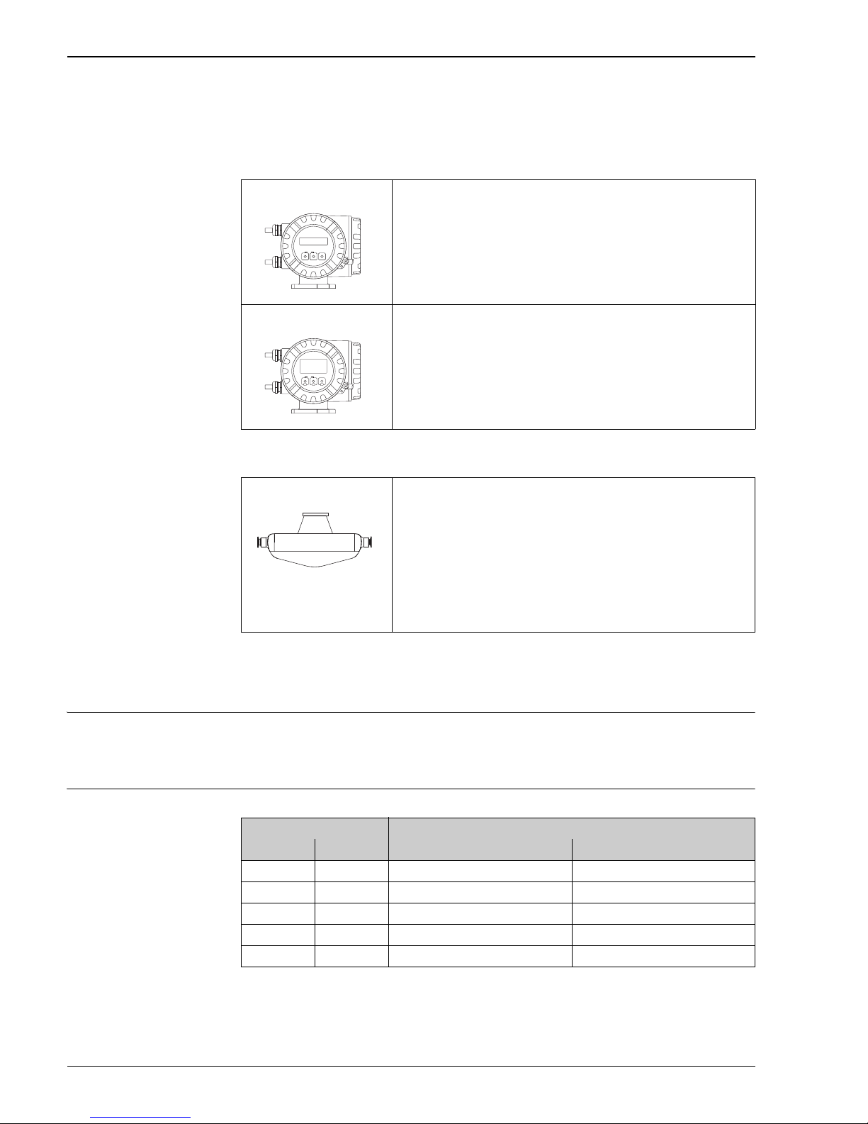
Measuring system The measuring system consists of a transmitter and a sensor. Two versions are available:
• Compact version: transmitter and sensor form a mechanical unit.
• Remote version: transmitter and sensor are mounted physically separate from one another.
Transmitter
Sensor
Input
Measured variable • Mass flow (proportional to the phase difference between two sensors mounted on the measuring
tube to register a phase shift in the oscillation)
• Fluid density (proportional to resonance frequency of the measuring tube)
• Fluid temperature (measured with temperature sensors)
Measuring range Measuring ranges for liquids
Promass 80
a0003671
• Two-line liquid-crystal display
• Operation with push buttons
Promass 83
a0003672
• Four-line liquid-crystal display
• Operation with “Touch control”
• Application-specific Quick Setup
• Mass flow, volume flow, density and temperature measurement as well as
calculated variables (e.g. fluid concentrations)
S
a0006828
• Hygienic design and sensitive fluid handling
• Simultaneous measurement of flow, volume flow, density and
temperature (multivariable)
• Immune to process influences
• Nominal diameters DN 8 to 50 (³⁄" to 2")
•Materials:
– Sensor: stainless steel, 1.4301 (304)
– Measuring tube: stainless steel, 1.4539 (904L)
– Process connections: stainless steel, 1.4435 (316L); stainless steel,
1.4404 (316/316L)
– Surface quality: Ra
max
0.8 m (32 in) (mechanical polished)
Esc
E
-
+
Esc
E
+
–
DN Range for full scale values (liquids)
min(F)
to
max(F)
[mm] [in] [kg/h] [lb/min]
8³⁄ 0 to 2000 0 to 73.50
15 ½ 0 to 6500 0 to 238.9
25 1 0 to 18000 0 to 661.5
40 1 ½ 0 to 45000 0 to 1 654
50 2 0 to 70000 0 to 2 573

Proline Promass 80S, 83S
Endress+Hauser 5
Measuring ranges for gases
The full scale values depend on the density of the gas. Use the formula below to calculate the full scale
values:
max(G)
=
max(F)
·
(G)
/ x [kg/m3]
max(G)
= max. full scale value for gas [kg/h]
max(F)
= max. full scale value for liquid [kg/h]
(G)
= Gas density in [kg/m] at operating conditions
Here,
max(G)
can never be greater than
max(F)
Calculation example for gas:
• Sensor type: Promass S, DN 50
• Gas: air with a density of 60.3 kg/m (at 20 °C and 50 bar)
• Measuring range (liquid): 70000 kg/h
• x = 90 (for Promass S, DN 50)
Max. possible full scale value:
max(G)
=
max(F)
·
(G)
÷ x [kg/m] = 70000 kg/h · 60.3 kg/m ÷ 90 kg/m = 46900 kg/h
Recommended full scale values
See information in the "Limiting flow" section 23 ff.
Operable flow range Greater than 1000: 1. Flow rates above the preset full scale value do not overload the amplifier, i.e. the
totalizer values are registered correctly.
Input signal Status input (auxiliary input)
U = 3 to 30 V DC, R
i
= 5 k, galvanically isolated.
Configurable for: totalizer reset, positive zero return, error message reset, zero point adjustment start,
batching start/stop (optional), totalizer reset for batching (optional).
Status input (auxiliary input) with PROFIBUS DP
U = 3 to 30 V DC, R
i
= 3 k, galvanically isolated.
Switch level: ±3 to ±30 V DC, independent of polarity.
Configurable for: positive zero return, error message reset, zero point adjustment start, batching start/
stop (optional), totalizer reset for batching (optional).
Status input (auxiliary input) with Modbus RS485
U = 3 to 30 V DC, R
i
= 3 k, galvanically isolated.
Switch level: ±3 to ±30 V DC, independent of polarity.
Configurable for: totalizer reset, positive zero return, error message reset, zero point adjustment start.
Current input (only Promass 83)
Active/passive selectable, galvanically isolated, resolution: 2 A
•Active: 4 to 20 mA, R
L
< 700 , U
out
= 24 V DC, short-circuit proof
• Passive: 0/4 to 20 mA, R
i
= 150 , U
max
= 30 V DC
DN
x
[mm] [in]
8³⁄"60
15 ½" 80
25 1" 90
40 1 ½" 90
50 2" 90

Proline Promass 80S, 83S
6 Endress+Hauser
Output
Output signal Promass 80
Current output:
Active/passive selectable, galvanically isolated, time constant selectable (0.05 to 100 s), full scale
value selectable, temperature coefficient: typically 0.005% o.r./°C, resolution: 0.5 A
• Active: 0/4 to 20 mA, R
L
< 700 (for HART: RL 250 )
• Passive: 4 to 20 mA; supply voltage U
S
18 to 30 V DC; Ri 150
Pulse/frequency output:
Passive, open collector, 30 V DC, 250 mA, galvanically isolated.
• Frequency output: full scale frequency 2 to 1000 Hz (f
max
= 1250 Hz), on/off ratio 1:1, pulse width
max. 2 s
• Pulse output: pulse value and pulse polarity selectable, pulse width configurable (0.5 to 2000 ms)
PROFIBUS PA interface:
• PROFIBUS PA in accordance with EN 50170 Volume 2, IEC 61158-2 (MBP), galvanically isolated
• Profile Version 3.0
• Current consumption = 11 mA
• Permitted supply voltage: 9 to 32 V
• Bus connection with integrated reverse polarity protection
• Error current FDE (Fault Disconnection Electronic) = 0 mA
• Data transmission rate: 31.25 kBit/s
• Signal encoding: Manchester II
• Function blocks: 4 × Analog Input, 2 × Totalizer
• Output data: Mass flow, Volume flow, Density, Temperature, Totalizer
• Input data: Positive zero return (ON/OFF), Zero point adjustment, Measuring mode, Totalizer
control
• Bus address can be configured via miniature switches or via the local display (optional)
Promass 83
Current output:
Active/passive selectable, galvanically isolated, time constant selectable (0.05 to 100 s), full scale
value selectable, temperature coefficient: typically 0.005% o.r./°C, resolution: 0.5 A
• Active: 0/4 to 20 mA, R
L
< 700 (for HART: RL 250 )
• Passive: 4 to 20 mA; supply voltage US 18 to 30 V DC; Ri 150
Pulse/frequency output:
active/passive selectable, galvanically isolated
• Active: 24 V DC, 25 mA (max. 250 mA during 20 ms), R
L
> 100
• Passive: open collector, 30 V DC, 250 mA
• Frequency output: full scale frequency 2 to 10000 Hz (f
max
= 12500 Hz), on/off ratio 1:1, pulse width
max. 2 s
• Pulse output: pulse value and pulse polarity selectable, pulse width configurable (0.05 to 2000 ms)
HART protocol
Order code "Power supply; Display", option A, B, C, D, E, F, G, H, X, 7, 8 (HART 5)
• Valid until software: 3.01.XX
Order code "Power supply; Display", option P, Q, R, S, T, U, 4, 5 (HART 7)
• Valid as of software: 3.07.XX
PROFIBUS DP interface:
• PROFIBUS DP in accordance with EN 50170 Volume 2
• Profile Version 3.0
• Data transmission rate: 9.6 kBaud to 12 MBaud
• Automatic data transmission rate recognition
• Signal encoding: NRZ Code
• Function blocks: 6 × Analog Input, 3 × Totalizer

Proline Promass 80S, 83S
Endress+Hauser 7
• Output data: Mass flow, Volume flow, Corrected volume flow, Density, Reference density,
Temperature, Totalizers 1 to 3
• Input data: Positive zero return (ON/OFF), Zero point adjustment, Measuring mode, Totalizer
control
• Bus address can be configured via miniature switches or via the local display (optional)
• Available output combination 8
PROFIBUS PA interface:
• PROFIBUS PA in accordance with EN 50170 Volume 2, IEC 61158-2 (MBP), galvanically isolated
• Data transmission rate: 31.25 kBit/s
• Current consumption: 11 mA
• Permitted supply voltage: 9 to 32 V
• Bus connection with
integrated reverse polarity protection
• Error current FDE (Fault Disconnection Electronic): 0 mA
• Signal encoding: Manchester II
• Function blocks: 6 × Analog Input, 3 × Totalizer
• Output data: Mass flow, Volume flow, Corrected volume flow, Density, Reference density,
Temperature, Totalizers 1 to 3
• Input data: Positive zero return (ON/OFF), Zero point adjustment, Measuring mode, Totalizer
control
• Bus address can be configured via miniature switches or via the local display (optional)
• Available output combination 8
Modbus interface:
• Modbus device type: slave
• Address range: 1 to 247
• Supported function codes: 03, 04, 06, 08, 16, 23
• Broadcast: supported with the function codes 06, 16, 23
• Physical interface: RS485 in accordance with EIA/TIA-485 standard
• Supported baud rate: 1200, 2400, 4800, 9600, 19200, 38400, 57600, 115200 Baud
• Transmission mode: RTU or ASCII
• Response times:
Direct data access = typically 25 to 50 ms
Auto-scan buffer (data range) = typically 3 to 5 ms
• Possible output combinations 8
FOUNDATION Fieldbus interface:
• FOUNDATION Fieldbus H1, IEC 61158-2, galvanically isolated
• Data transmission rate: 31.25 kBit/s
• Current consumption: 12 mA
• Permitted supply voltage: 9 to 32 V
• Error current FDE (Fault Disconnection Electronic): 0 mA
• Bus connection with integrated reverse polarity protection
• Signal encoding: Manchester II
•ITK Version 5.01
•Function blocks:
– 8 × Analog Input (Execution time: per18 ms)
– 1 × Digital Output (18 ms)
– 1 × PID (25 ms)
– 1 × Arithmetic (20 ms)
– 1 × Input Selector (20 ms)
– 1 × Signal Characterizer (20 ms)
–1 × Integrator (18 ms)
•Number of VCRs: 38
• Number of link objects in VFD: 40
• Function blocks: 7 × Analog Input, 1 × Digital Output, 1 × PID
• Output data: Mass flow, Volume flow, Corrected volume flow, Density, Reference density,
Temperature, Totalizers 1 to 3
• Input data: Positive zero return (ON/OFF), Zero point adjustment, Measuring mode, Reset totalizer
• Link Master (LM) function is supported
Proline Promass 80S, 83S
8 Endress+Hauser
Signal on alarm Current output
Failsafe mode selectable (e.g. in accordance with NAMUR Recommendation NE 43)
Pulse/frequency output
Failsafe mode selectable
Status output (Promass 80)
Nonconductive in the event of a fault or if the power supply fails
Relay output (Promass 83)
Dead in the event of a fault or if the power supply fails
Load See "Output signal"
Low flow cut off Switch points for low flow cut off are selectable.
Galvanic isolation All circuits for inputs, outputs, and power supply are galvanically isolated from each other.
Switching output Status output (Promass 80)
• Open collector
• Max. 30 V DC, 250 mA
• Galvanically isolated
• Configurable for: error messages, Empty Pipe Detection (EPD), flow direction, limit values
Relay output (Promass 83)
• Max. 30 V, 0.5 A AC; 60 V, 0.1 A DC
• Galvanically isolated
• Normally closed (NC or break) or normally open (NO or make) contacts available
(factory setting: relay 1 = NO, relay 2 = NC)
Power supply
Terminal assignment Promass 80
Order characteristic
for "inputs/outsputs"
Terminal No. (inputs/outputs)
20 (+) / 21 (–) 22 (+) / 23 (–) 24 (+) / 25 (–) 26 (+) / 27 (–)
A - - Frequency output Current output, HART
D Status input Status output Frequency output Current output, HART
H - - - PROFIBUS PA
S--
Frequency output
Ex i, passive
Current output Ex i
active, HART
T--
Frequency output
Ex i, passive
Current output Ex i
passive, HART
8 Status input Frequency output Current output 2 Current output 1, HART

Proline Promass 80S, 83S
Endress+Hauser 9
Promass 83
The inputs and outputs on the communication board can be either permanently assigned (fixed) or
variable (flexible), depending on the version ordered (see table). Replacements for modules which are
defective or which have to be replaced can be ordered as accessories.
Order characteristic
for "inputs/outsputs",
option
Terminal No. (inputs/ outputs)
20 (+) / 21 (–) 22 (+) / 23 (–) 24 (+) / 25 (–) 26 (+) / 27 (–)
Fixed communication boards (permanent assignment)
A - - Frequency output Current output, HART
B Relay output Relay output Frequency output Current output, HART
F ---PROFIBUS PA, Ex i
G---
FOUNDATION
Fieldbus Ex i
H ---PROFIBUS PA
J--
+5V (ext.
termination)
PROFIBUS DP
K - - - FOUNDATION Fieldbus
Q - - Status input Modbus RS485
R--
Current output 2
Ex i, active
Current output 1
Ex i active, HART
S--
Frequency output
Ex i, passive
Current output Ex i
active, HART
T--
Frequency output
Ex i, passive
Current output Ex i
passive, HART
U--
Current output 2
Ex i, passive
Current output 1
Ex i passive, HART
Flexible communication boards
C Relay output 2 Relay output 1 Frequency output Current output, HART
D Status input Relay output Frequency output Current output, HART
E Status input Relay output Current output 2 Current output 1, HART
L Status input Relay output 2 Relay output 1 Current output, HART
M Status input Frequency output 2 Frequency output 1 Current output, HART
N Current output Frequency output Status input Modbus RS485
P Current output Frequency output Status input PROFIBUS DP
V Relay output 2 Relay output 1 Status input PROFIBUS DP
W Relay output Current output 3 Current output 2 Current output 1, HART
0 Status input Current output 3 Current output 2 Current output 1, HART
2 Relay output Current output 2 Frequency output Current output 1, HART
3Current inputRelay output Current output 2 Current output 1, HART
4 Current input Relay output Frequency output Current output, HART
5 Status input Current input Frequency output Current output, HART
6 Status input Current input Current output 2 Current output 1, HART
7 Relay output 2 Relay output 1 Status input Modbus RS485

Proline Promass 80S, 83S
10 Endress+Hauser
Supply voltage 85 to 260 V AC, 45 to 65 Hz
20 to 55 V AC, 45 to 65 Hz
16 to 62 V DC
Power consumption AC: <15 VA (including sensor)
DC: <15 W (including sensor)
Switch-on current:
• Max. 13.5 A (< 50 ms) at 24 V DC
• Max. 3 A (< 5 ms) at 260 V AC
Power supply failure Promass 80
Lasting min. 1 power cycle:
• EEPROM saves measuring system data if the power supply fails
• HistoROM/S-DAT: exchangeable data storage chip with sensor specific data (nominal diameter,
serial number, calibration factor, zero point, etc.)
Promass 83
Lasting min. 1 power cycle:
• EEPROM and T-DAT save the measuring system data if the power supply fails.
• HistoROM/S-DAT: exchangeable data storage chip with sensor specific data (nominal diameter,
serial number, calibration factor, zero point, etc.)
Proline Promass 80S, 83S
Endress+Hauser 11
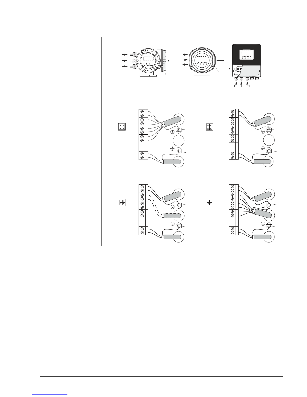
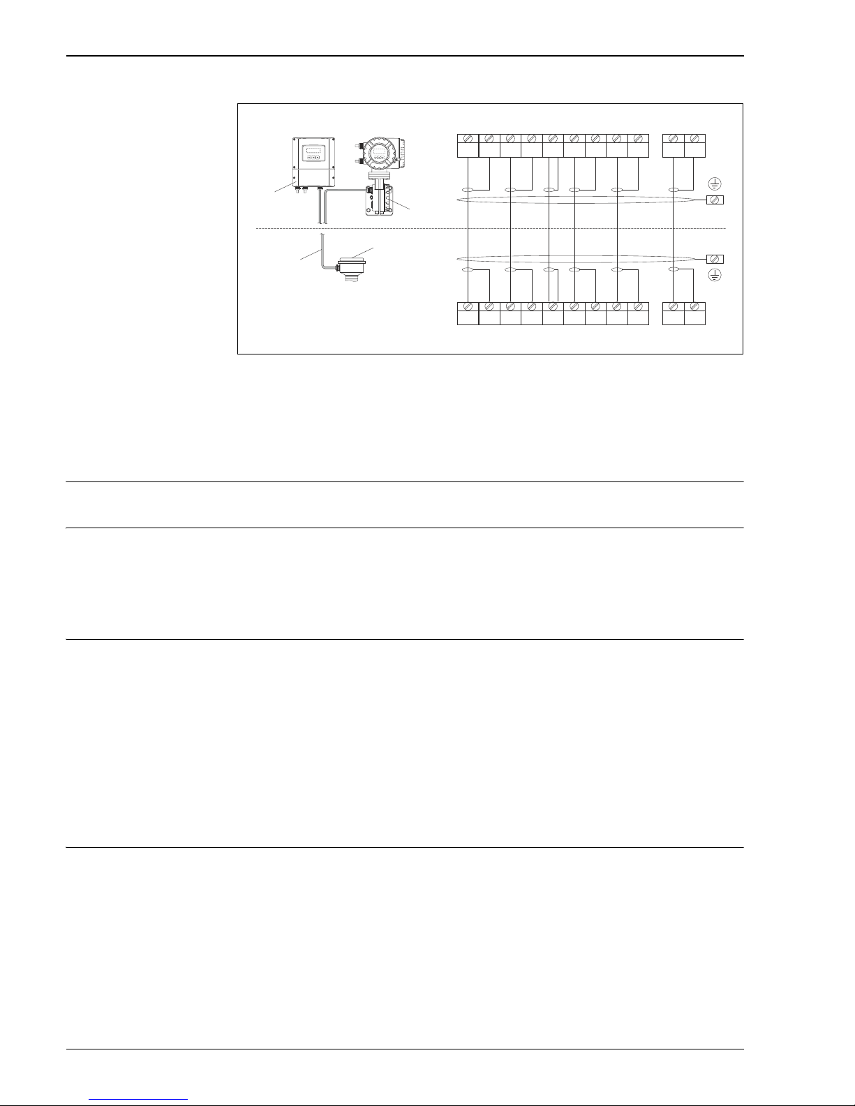
Electrical connection
a0002441
Connecting the transmitter, cable cross-section: max. 2.5 mm
2
A View A (field housing)
B View B (stainless steel field housing)
C View C (wall-mount housing)
*) Fixed communication board
**) Flexible communication board
a Connection compartment cover
b Cable for power supply: 85 to 260 V AC, 20 to 55 V AC, 16 to 62 V DC
Terminal No. 1: L1 for AC, L+ for DC
Terminal No. 2: N for AC, L– for DC
c Ground terminal for protective ground
d Signal cable: see Terminal assignment → 8
Fieldbus cable:
Terminal No. 26: DP (B) / PA (+) / FF (+) / Modbus RS485 (B) / (PA, FF: with reverse polarity protection)
Terminal No. 27: DP (A) / PA (–) / FF (–) / Modbus RS485 (A) / (PA, FF: with reverse polarity protection)
e Ground terminal for signal cable shield / fieldbus cable / RS485 line
f Service adapter for connecting service interface FXA 193 (Fieldcheck, FieldCare)
g Signal cable: see Terminal assignment → 8
Cable for external termination (only for PROFIBUS DP with permanent assignment communication board):
Terminal No. 24: +5 V
Terminal No. 25: DGND
HART*
PROFIBUS DP**
MODBUS RS485**
L1 (L+) 1
N (L-) 2
25
24
–
+
23
22
–
+
21
20
–
+
PROFIBUS PA*
FOUNDATION Fieldbus*
27
26
L1 (L+) 1
N (L-) 2
25
24
–
+
23
22
–
+
21
20
–
+
A (RxD/TxD-N)
B (RxD/TxD-P)
27
26
PA(–)/FF(–)
PA(+)/FF(+)
L1 (L+) 1
N (L-) 2
25–
24+
23
22
–
+
21
20
–
+
27
26
A (RxD/TxD-N)
B (RxD/TxD-P)
d
c
e
b
d
c
e
b
g
d
c
e
b
g
PROFIBUS DP*
d
c
e
b
–27
+ 26
–25
+ 24
–23
+ 22
–21
+ 20
N (L-) 2
f f
f f
a
a
d
b
a
AB
C
g
d
b
g
(d)
b
d/(g)
L1 (L+) 1
Proline Promass 80S, 83S
12 Endress+Hauser
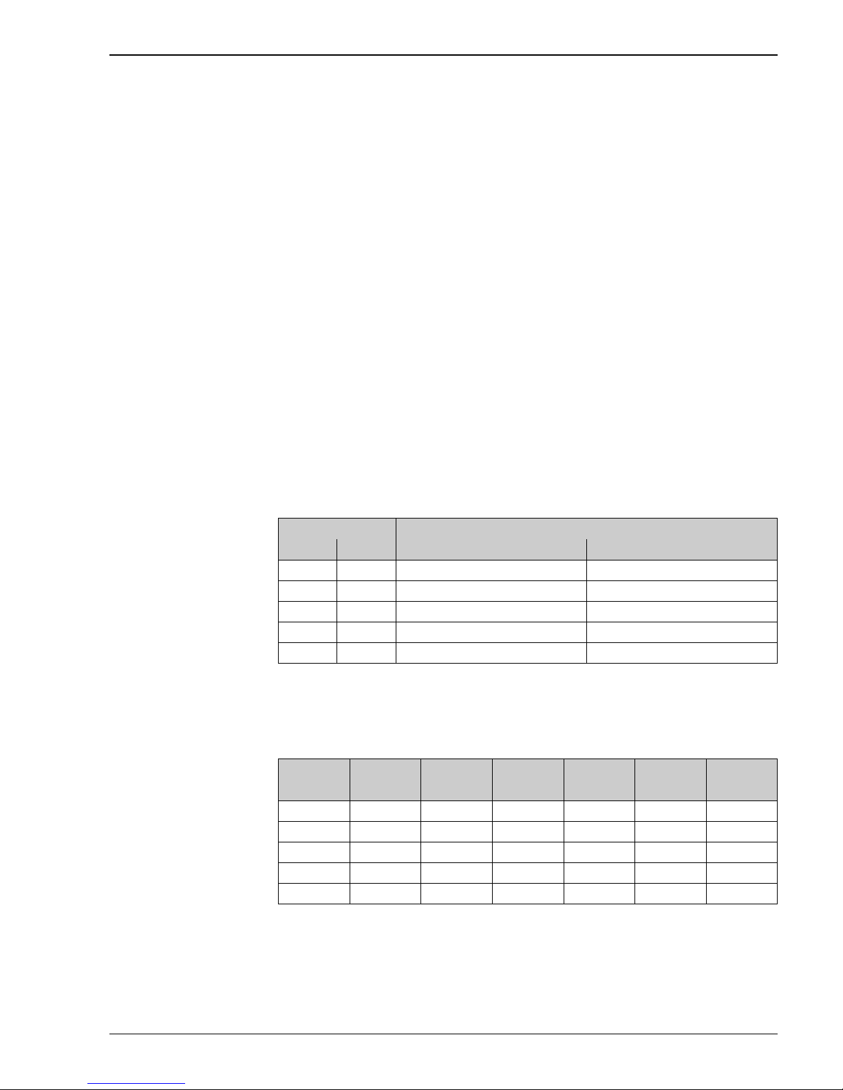
Electrical connection Remote
version
a0003681
Connecting the remote version
a Wall-mount housing: non-hazardous area and ATEX II3G, zone 2 → see separate "Ex documentation"
b Wall-mount housing: ATEX II2G, Zone 1 /FM/CSA → see separate "Ex documentation"
c Connection housing sensor
d Cover for connection compartment or connection housing
e Connecting cable
Terminal No.: 4/5 = gray; 6/7 = green; 8 = yellow; 9/10 = pink; 1¹⁄₁₂ = white; 41/42 = brown
Potential equalization No special measures for potential equalization are required. For instruments for use in hazardous
areas, observe the corresponding guidelines in the specific Ex documentation.
Cable entries Power-supply and signal cables (inputs/outputs):
• Cable entry M20 × 1.5 (8 to 12 mm / 0.31" to 0.47")
• Thread for cable entries, ½" NPT, G ½"
Connecting cable for remote version:
• Cable entry M20 × 1.5 (8 to 12 mm / 0.31" to 0.47")
• Thread for cable entries, ½" NPT, G ½"
Cable specification
Remote version
• 6 × 0.38 mm
PVC cable with common shield and individually shielded cores
• Conductor resistance: 50 /km (0.015 /ft)
• Capacitance: core/shield: 420 pF/m (128 pF/ft)
• Cable length: max. 20 m (65 ft)
• Permanent operating temperature: max. +105 °C (+221 °F)
Operation in zones of severe electrical interference:
The measuring device complies with the general safety requirements in accordance with EN 61010,
the EMC requirements of IEC/EN 61326, and NAMUR recommendation NE 21/43.
Performance characteristics
Reference operating
conditions
• Error limits following ISO 11631
• Water with 15 to 45 °C (59 to 113 °F); 2 to 6 bar (29 to 87 psi)
• Data according to calibration protocol
• Accuracy based on accredited calibration rigs that are traced to ISO 17025
To obtain measured errors, use the Applicator sizing tool Applicator: 51.
S1 S1 S2 S2 GND TM TM TT TT
++ ++
++ ++
S1 S1 S2 S2 GND TM TM TT TT
a
b
c
d
d
d
e
4 5 6 7 8 9 10 11 12 41 42
4 5 6 7 8 9 10 11 12 41 42
Proline Promass 80S, 83S
Endress+Hauser 13
Maximum measured error Design fundamentals 15
o.r. = of reading; 1 g/cm3= 1 kg/l; T = fluid temperature
Base accuracy
Mass flow and volume flow (liquids)
Promass 83S:
• ±0.10% o.r.
Promass 80S:
• ±0.15% o.r.
Mass flow (gases)
±0.50% o.r.
Density (liquids)
• Reference conditions: ±0.0005 g/cm
3
• Field density calibration: ±0.0005 g/cm3 (valid after field density calibration under process
conditions)
• Standard density calibrations: ±0.01 g/cm
3
(valid over the entire measuring range of the sensor
19)
• Special density calibration: ±0.002 g/cm
3
(optional, valid range: +5 to +80 °C (+41 to +176 °F) and
0to2.0 g/cm)
Temperature
±0.5 °C ± 0.005 · T °C (±1 °F ± 0.003 · (T - 32) °F)
Zero point stability
Flow values
Flow values as turndown parameter depending on nominal diameter.
SI units
DN Zero point stability
[mm] [in] [kg/h] [lb/min]
8³⁄" 0.20 0.007
15 ½" 0.65 0.024
25 1" 1.80 0.066
40 1½" 4.50 0.165
50 2" 7.00 0.257
DN 1:1 1:10 1:20 1:50 1:100 1:500
[mm] [kg/h] [kg/h] [kg/h] [kg/h] [kg/h] [kg/h]
8 2000 200.0 100.0 40.00 20.00 4.000
15 6500 650.0 625.0 130.0 65.00 13.00
25 18000 18 00 900.0 360.0 180.0 36.00
40 45000 45 00 2 250 900.0 45 0.0 90.00
50 70000 7 000 3500 1400 700.0 140.0

Proline Promass 80S, 83S
14 Endress+Hauser
US units
Accuracy of outputs
o.r. = of reading; o.f.s. = of full scale value
The output accuracy must be factored into the measured error if analog outputs are used, but can be
ignored for fieldbus outputs (e.g. Modbus RS485, EtherNet/IP).
Current output
Accuracy: Max. ±0.05 % o.f.s. or ±5 A
Pulse/frequency output
Accuracy: Max. ±50 % ppm o.r.
Repeatability Design fundamentals 15
o.r. = of reading; 1 g/cm
3
= 1 kg/l; T = fluid temperature
Base repeatability
Mass flow and volume flow (liquids)
Promass 80S, 83S: ±0.05% o.r.
Mass flow (gases)
Promass 80S, 83S: ±0.25% o.r.
Density (liquids)
±0.00025 g/cm
3
Temperature
±0.25 °C ± 0.0025 · T °C (±0.45 °F ± 0.0015 · (T–32) °F)
Response time • The response time depends on the configuration (damping).
• Response time in the event of erratic changes in the measured variable (only mass flow): after
100 ms 95 % of the full scale value.
Influence of fluid
temperature
When there is a difference between the temperature for zero point adjustment and the process
temperature, the typical measured error of the Promass sensor is ±0.0002% of the full scale value / °C
(±0.0001% of the full scale value / °F).
DN 1:1 1:10 1:20 1:50 1:100 1:500
[in] [lb/min] [lb/min] [lb/min] [lb/min] [lb/min] [lb/min]
³⁄" 73.50 7.350 3.675 1.470 0.735 0.147
½" 238.9 23.89 11.95 4.778 2.389 0.478
1" 661.5 66.15 33.08 13.23 6.615 1.323
1½" 1654 165.4 82.70 33.08 16.54 3.308
2" 2573 257.3 128.7 51.46 25.73 5.146
Proline Promass 80S, 83S
Endress+Hauser 15
Influence of fluid pressure The table below shows the effect on accuracy of mass flow due to a difference between calibration
pressure and process pressure.
Design fundamentals o.r. = of reading
BaseAccu = base accuracy in % o.r.
BaseRepeat = base repeatability in % o.r.
MeasValue = measured value (in flow units consistent with the zero point stability value 13)
ZeroPoint = zero point stability
Calculation of the maximum measured error depending on flowrate
Calculation of the repeatability depending on flowrate
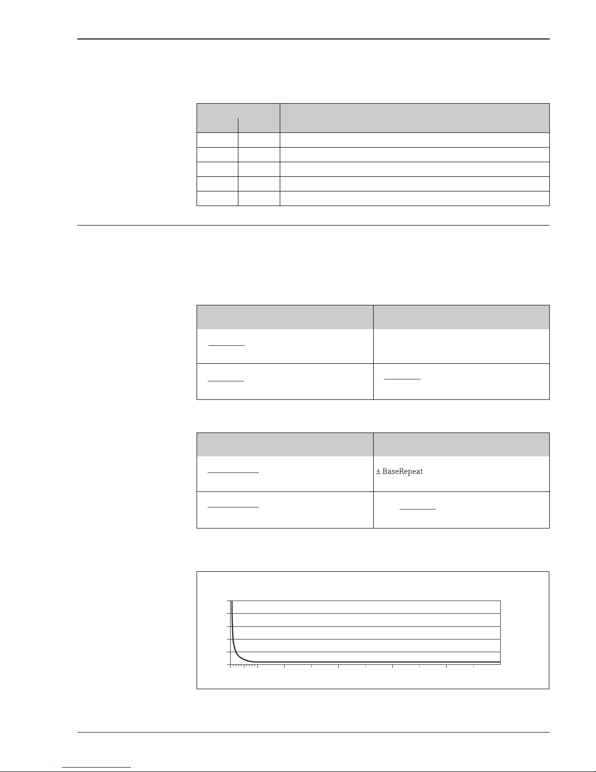
Example for maximum measured error
A0016709
E = Error: Maximum measured error as % o.r. (example Promass 83S)
Q = Flow rate as %
DN Promass S
[mm] [in] [% o.r./bar]
8³⁄" –0.002
15 ½" –0.006
25 1" –0.005
40 1½" –0.005
50 2" –0.005
Flowrate (in flow units consistent with the zero
point stability value 13)
Maximum measured error in % o.r.
A0021332
A0021339
A002133
A0021334
Flowrate (in flow units consistent with the zero
point stability value 13)
Repeatability in % o.r.
A0021335
A0021340
A0021336
A0021337
ZeroPoint
BaseAccu
⋅ 100
³
± BaseAccu
ZeroPoint
BaseAccu
⋅
100
<
ZeroPoint
MeasValue
⋅ 100
±
½⋅ZeroPoint
BaseRepeat
⋅
100
³
½⋅ZeroPoint
BaseRepeat
⋅
100
<
ZeroPoint
MeasValue
⋅
100
½⋅±
E [%]
0 102030405060
0
0.5
1.0
1.5
2.0
2.5
70 80 90 100
Q [%]
Proline Promass 80S, 83S
16 Endress+Hauser
Installation
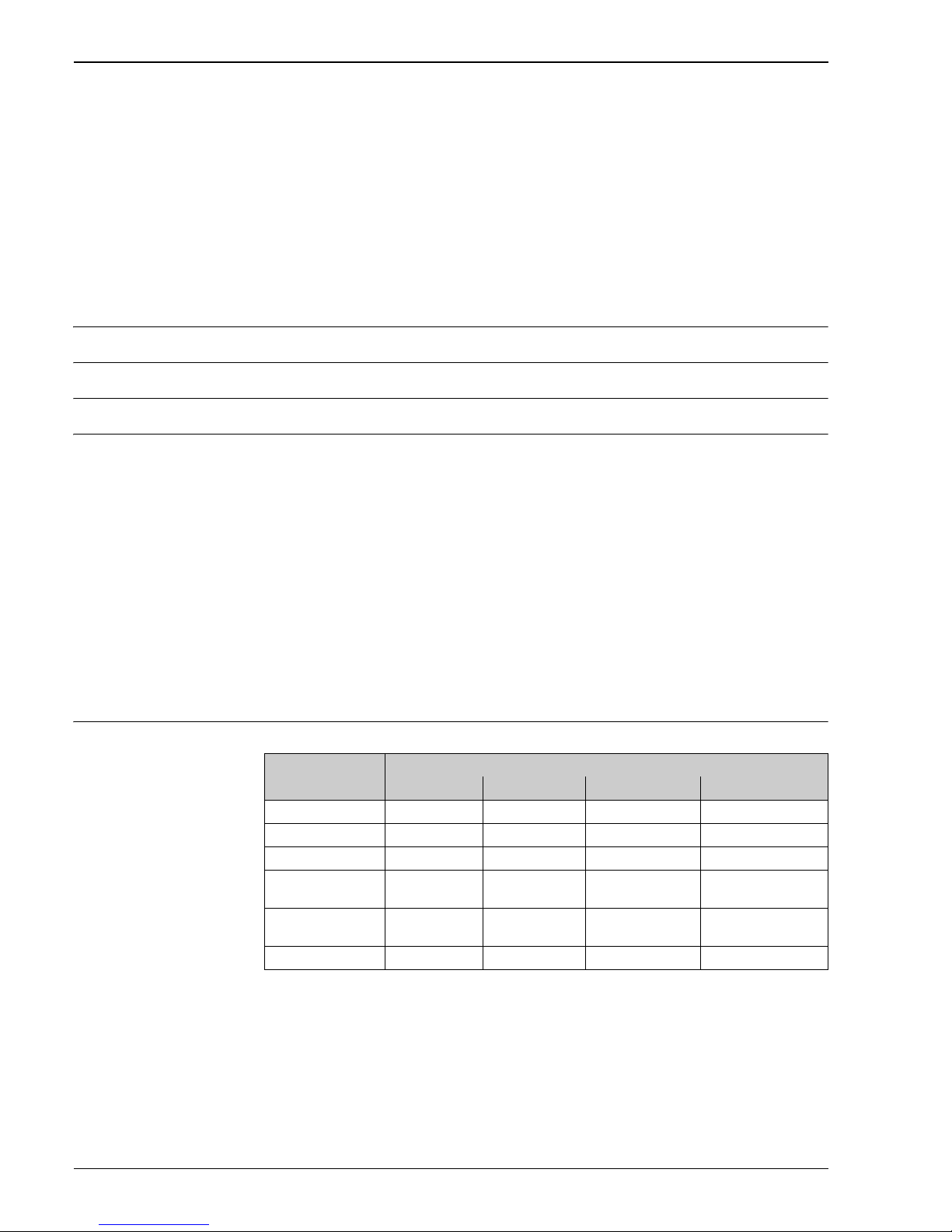
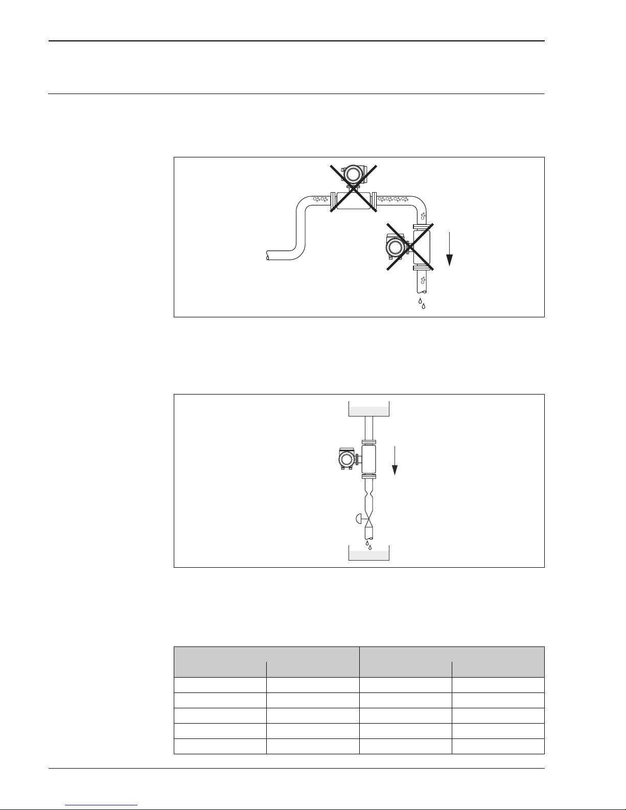
Mounting location Entrained air or gas bubbles in the measuring tube can result in an increase in measuring errors.
Therefore, avoid the following mounting locations in the pipe installation:
• Highest point of a pipeline. Risk of air accumulating.
• Directly upstream of a free pipe outlet in a vertical pipeline.
a0003605
Mounting location
Notwithstanding the above, the installation proposal below permits installation in an open vertical
pipeline. Pipe restrictions or the use of an orifice with a smaller cross-section than the nominal
diameter prevent the sensor running empty while measurement is in progress.
a0003597
Installation in a down pipe (e.g. for batching applications)
1 Supply tank
2Sensor
3 Orifice plate, pipe restriction (see Table following page)
4Valve
5Batching tank
1
2
3
4
5
DN Orifice plate, pipe restriction
[mm] [in] [mm] [in]
8³⁄" 60.24
15 ½" 10 0.39
25 1" 14 0.55
40 1½" 22 0.87
50 2" 28 1.10
Proline Promass 80S, 83S
Endress+Hauser 17
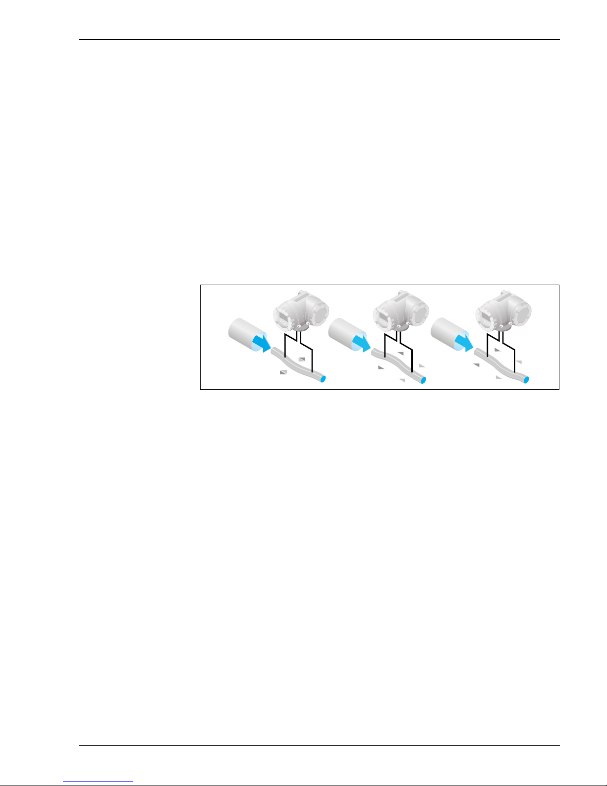
Orientation Make sure that the direction of the arrow on the nameplate of the sensor matches the direction of flow
(direction of fluid flow through the pipe.
Vertical (Fig. V)
Recommended orientation with upward direction of flow. When fluid is not flowing, entrained solids
will sink down and gases will rise away from the measuring tube. The measuring tubes can be
completely drained and protected against solids buildup.
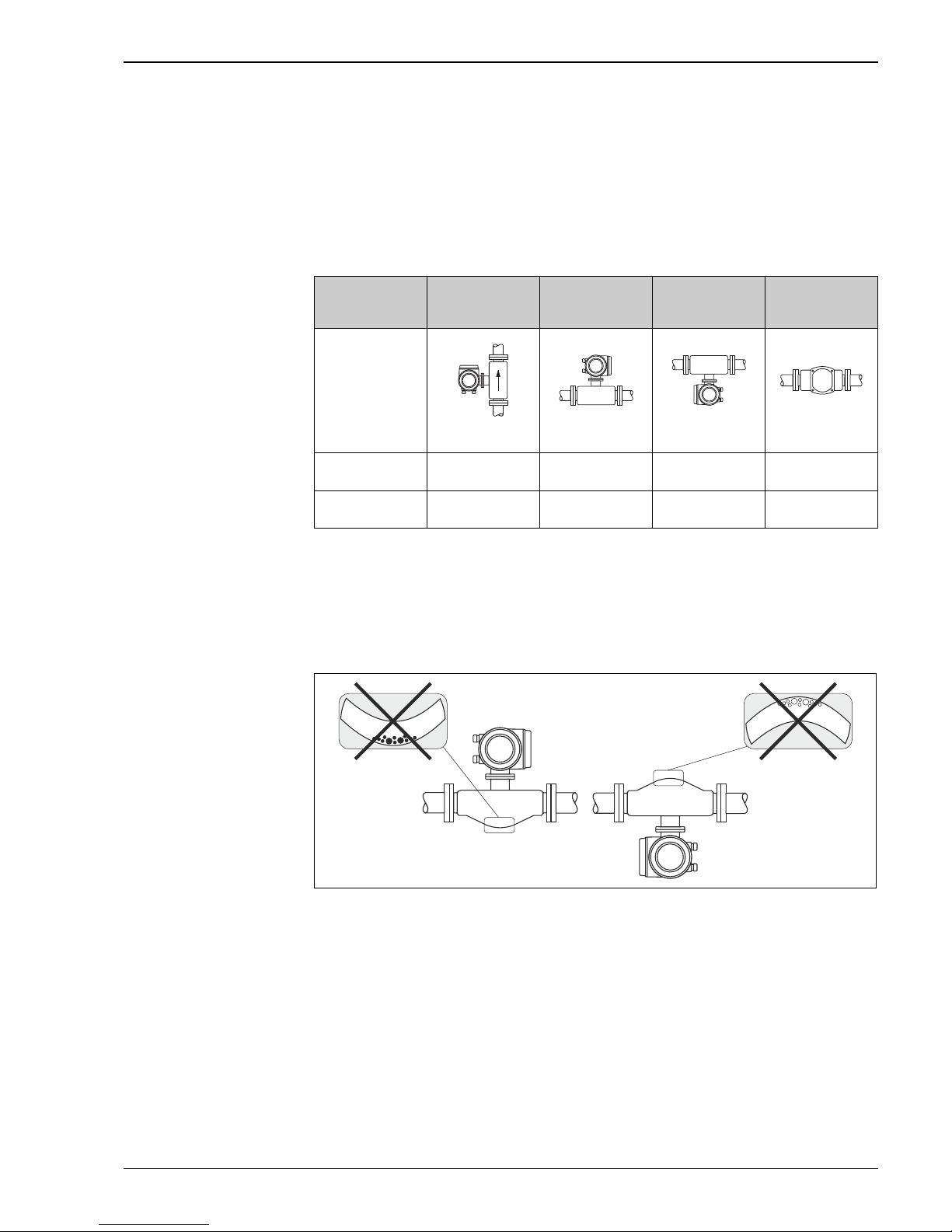
Horizontal (Fig. H1, H2, H3)
The transmitter can be installed in any orientation in a horizontal pipe run.
When using a bent measuring tube and horizontal installation, the position of the sensor has to be
matched to the fluid properties!
a0004581
Horizontal installation for sensors with a bent measuring tube
1 Not suitable for fluids with entrained solids. Risk of solids accumulating.
2 Not suitable for outgassing fluids. Risk of air accumulating.
Orientation: Vertikal Horizontal,
Transmitter head
up
Horizontal,
Transmitter head
down
Horizontal,
Transmitter head
to the side
a0004572
Fig. V
a0004576
Fig. H1
a0004580
Fig. H2
a0007558
Fig. H3
Standard,
Compact version
1)
Standard,
Remote version
1)
= Recommended orientation; = Orientation recommended in certain situations;
= Impermissible orientation
1)
To ensure that the maximum permitted ambient temperature for the transmitter is not exceeded, for lowtemperature fluids, we recommend the horizontal orientation with the transmitter head up (Fig. H1) or the
vertical orientation (Fig. V).
1
2
 Loading...