

Endress+Hauser Proline Promass 80H, Proline Promass 83H Technical Information
Technical Information
Proline Promass 80H, 83H
Coriolis Mass Flow Measuring System
The single-tube system with a "fit-and-forget" design:
does not harm the material being measured – chemical-resistant
materials
Application
The Coriolis measuring principle operates independently
of physical fluid properties, such as viscosity and density.
• Extremely accurate measurement of liquids such as
oils, lubricants, liquefied gases, paints, cleaning agents
and solvents
• Fluid temperatures up to +200 °C
• Process pressures up to 40 bar
• Mass flow measurement up to 70 t/h
Approvals for hazardous area:
• ATEX, FM, CSA, TIIS
Connection to all common process control systems:
• HART, PROFIBUS PA/DP, FOUNDATION Fieldbus,
MODBUS
Relevant safety aspects:
• Secondary containment (up to 25 bar), Pressure
Equipment Directive, SIL-2
Your benefits
The Promass measuring devices make it possible to
simultaneously record several process variables
(mass/density/temperature) for various process
conditions during measuring operation.
The uniform Proline transmitter concept includes:
• Modular device and operating concept resulting in a
higher degree of efficiency
• Software options for batching and concentration
measurement for extended range of application
• Diagnostic ability and data back-up for increased
process quality
The Promass sensors, tried and tested in over
100000 applications, offer:
• Multivariable flow measurement in compact design
• Insensitivity to vibrations thanks to balanced singletube measuring system
• Efficient protection against forces from piping thanks
to robust construction
• Easy installation without taking inlet and outlet runs
into account
TI074D/06/en/12.06
71036056

Table of contents
Proline Promass 80H, 83H
Function and system design. . . . . . . . . . . . . . . . . . . . . 3
Measuring principle . . . . . . . . . . . . . . . . . . . . . . . . . . . . . . . . . . . 3
Measuring system . . . . . . . . . . . . . . . . . . . . . . . . . . . . . . . . . . . . . 4
Input . . . . . . . . . . . . . . . . . . . . . . . . . . . . . . . . . . . . . . 5
Measured variable . . . . . . . . . . . . . . . . . . . . . . . . . . . . . . . . . . . . 5
Measuring range . . . . . . . . . . . . . . . . . . . . . . . . . . . . . . . . . . . . . . 5
Operable flow range . . . . . . . . . . . . . . . . . . . . . . . . . . . . . . . . . . . 6
Input signal . . . . . . . . . . . . . . . . . . . . . . . . . . . . . . . . . . . . . . . . . 6
Output . . . . . . . . . . . . . . . . . . . . . . . . . . . . . . . . . . . . . 6
Output signal . . . . . . . . . . . . . . . . . . . . . . . . . . . . . . . . . . . . . . . . 6
Signal on alarm . . . . . . . . . . . . . . . . . . . . . . . . . . . . . . . . . . . . . . 8
Load . . . . . . . . . . . . . . . . . . . . . . . . . . . . . . . . . . . . . . . . . . . . . . 8
Low flow cut off . . . . . . . . . . . . . . . . . . . . . . . . . . . . . . . . . . . . . . 8
Galvanic isolation . . . . . . . . . . . . . . . . . . . . . . . . . . . . . . . . . . . . . 8
Switching output . . . . . . . . . . . . . . . . . . . . . . . . . . . . . . . . . . . . . 8
Power supply . . . . . . . . . . . . . . . . . . . . . . . . . . . . . . . . 9
Electrical connection Measuring unit . . . . . . . . . . . . . . . . . . . . . . 9
Electrical connection, terminal assignment . . . . . . . . . . . . . . . . . 10
Electrical connection Remote version . . . . . . . . . . . . . . . . . . . . . 11
Supply voltage . . . . . . . . . . . . . . . . . . . . . . . . . . . . . . . . . . . . . . 11
Cable entries . . . . . . . . . . . . . . . . . . . . . . . . . . . . . . . . . . . . . . . 11
Cable specification
Remote version . . . . . . . . . . . . . . . . . . . . . . . . . . . . . . . . . . . . . 12
Power consumption . . . . . . . . . . . . . . . . . . . . . . . . . . . . . . . . . . 12
Power supply failure . . . . . . . . . . . . . . . . . . . . . . . . . . . . . . . . . . 12
Potential equalization . . . . . . . . . . . . . . . . . . . . . . . . . . . . . . . . . 12
Mechanical construction . . . . . . . . . . . . . . . . . . . . . . 21
Design / dimensions . . . . . . . . . . . . . . . . . . . . . . . . . . . . . . . . . 21
Weight . . . . . . . . . . . . . . . . . . . . . . . . . . . . . . . . . . . . . . . . . . . 26
Materials . . . . . . . . . . . . . . . . . . . . . . . . . . . . . . . . . . . . . . . . . . 27
Material load curves . . . . . . . . . . . . . . . . . . . . . . . . . . . . . . . . . . 27
Process connections . . . . . . . . . . . . . . . . . . . . . . . . . . . . . . . . . . 28
Human interface . . . . . . . . . . . . . . . . . . . . . . . . . . . . 28
Display elements . . . . . . . . . . . . . . . . . . . . . . . . . . . . . . . . . . . . 28
Unified control concept for both types of transmitter . . . . . . . . . . 28
Language groups . . . . . . . . . . . . . . . . . . . . . . . . . . . . . . . . . . . . 28
Remote operation . . . . . . . . . . . . . . . . . . . . . . . . . . . . . . . . . . . . 28
Certificates and approvals . . . . . . . . . . . . . . . . . . . . . 29
CE mark . . . . . . . . . . . . . . . . . . . . . . . . . . . . . . . . . . . . . . . . . . 29
C-Tick symbol . . . . . . . . . . . . . . . . . . . . . . . . . . . . . . . . . . . . . . 29
Ex approval . . . . . . . . . . . . . . . . . . . . . . . . . . . . . . . . . . . . . . . . 29
FOUNDATION Fieldbus certification . . . . . . . . . . . . . . . . . . . . 29
PROFIBUS DP/PA certification . . . . . . . . . . . . . . . . . . . . . . . . . 29
MODBUS certification . . . . . . . . . . . . . . . . . . . . . . . . . . . . . . . . 29
Other standards and guidelines . . . . . . . . . . . . . . . . . . . . . . . . . . 29
Pressure Equipment Directive . . . . . . . . . . . . . . . . . . . . . . . . . . 29
Functional safety . . . . . . . . . . . . . . . . . . . . . . . . . . . . . . . . . . . . 30
Ordering information. . . . . . . . . . . . . . . . . . . . . . . . . 30
Accessories . . . . . . . . . . . . . . . . . . . . . . . . . . . . . . . . 30
Documentation . . . . . . . . . . . . . . . . . . . . . . . . . . . . . 31
Performance characteristics. . . . . . . . . . . . . . . . . . . . 12
Reference operating conditions . . . . . . . . . . . . . . . . . . . . . . . . . . 12
Maximum measured error . . . . . . . . . . . . . . . . . . . . . . . . . . . . . 12
Repeatability . . . . . . . . . . . . . . . . . . . . . . . . . . . . . . . . . . . . . . . . 14
Influence of fluid temperature . . . . . . . . . . . . . . . . . . . . . . . . . . . 14
Influence of fluid pressure . . . . . . . . . . . . . . . . . . . . . . . . . . . . . . 14
Operating conditions: Installation . . . . . . . . . . . . . . . 15
Installation instructions . . . . . . . . . . . . . . . . . . . . . . . . . . . . . . . . 15
Inlet and outlet runs . . . . . . . . . . . . . . . . . . . . . . . . . . . . . . . . . . 18
Length of connecting cable . . . . . . . . . . . . . . . . . . . . . . . . . . . . . 18
System pressure . . . . . . . . . . . . . . . . . . . . . . . . . . . . . . . . . . . . . 18
Operating conditions: Environment . . . . . . . . . . . . . . 19
Ambient temperature range . . . . . . . . . . . . . . . . . . . . . . . . . . . . 19
Storage temperature . . . . . . . . . . . . . . . . . . . . . . . . . . . . . . . . . . 19
Degree of protection . . . . . . . . . . . . . . . . . . . . . . . . . . . . . . . . . . 19
Shock resistance . . . . . . . . . . . . . . . . . . . . . . . . . . . . . . . . . . . . . 19
Vibration resistance . . . . . . . . . . . . . . . . . . . . . . . . . . . . . . . . . . 19
Electromagnetic compatibility (EMC) . . . . . . . . . . . . . . . . . . . . . 19
Operating conditions: Process . . . . . . . . . . . . . . . . . . 19
Fluid temperature range . . . . . . . . . . . . . . . . . . . . . . . . . . . . . . . 19
Fluid pressure range (nominal pressure) . . . . . . . . . . . . . . . . . . . 19
Limiting flow . . . . . . . . . . . . . . . . . . . . . . . . . . . . . . . . . . . . . . . 19
Pressure loss . . . . . . . . . . . . . . . . . . . . . . . . . . . . . . . . . . . . . . . . 20
Registered trademarks . . . . . . . . . . . . . . . . . . . . . . . . 31
2 Endress+Hauser
Proline Promass 80H, 83H
Function and system design
Measuring principle The measuring principle is based on the controlled generation of Coriolis forces. These forces are always present
when both translational and rotational movements are superimposed.
FC = 2 · Δm (v · ω)
= Coriolis force
F
C
Δm = moving mass
ω = rotational velocity
v = radial velocity in rotating or oscillating system
The amplitude of the Coriolis force depends on the moving mass Δm, its velocity v in the system, and thus on
the mass flow. Instead of a constant angular velocity ω, the Promass sensor uses oscillation.
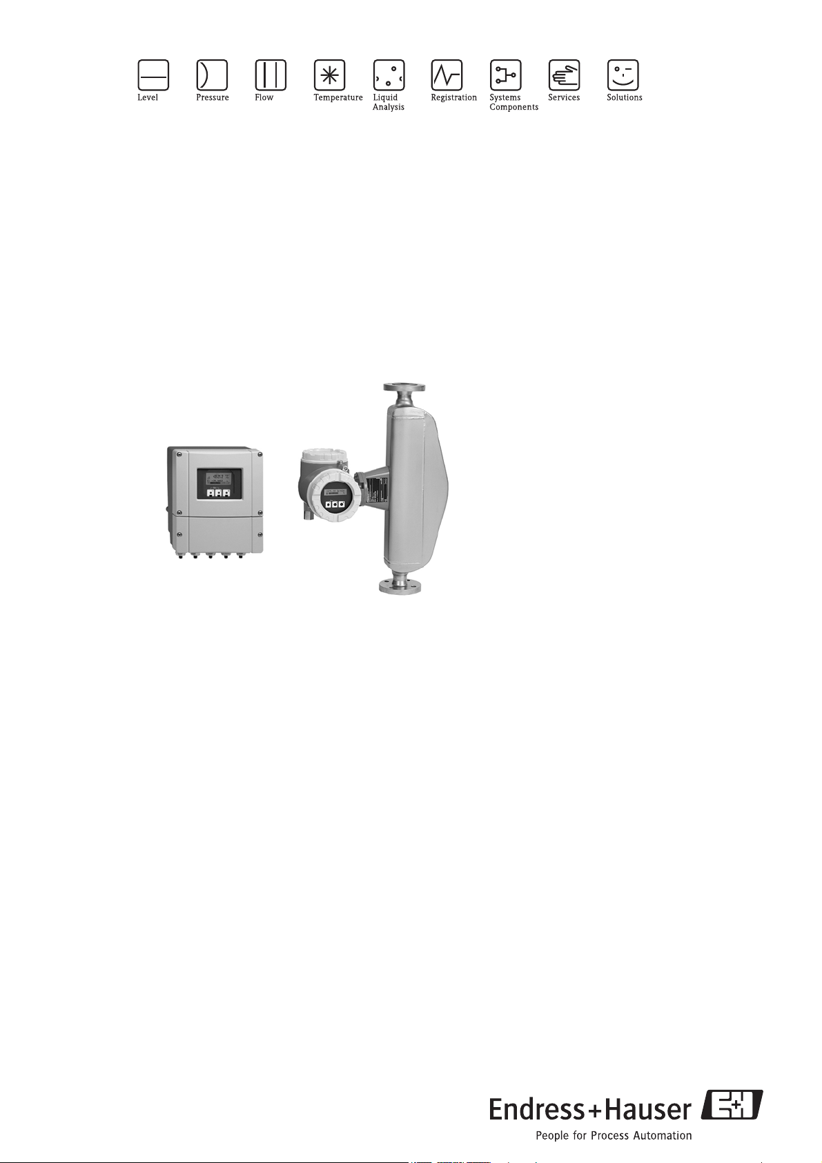
This causes the tube through which the fluid is flowing to oscillate. The Coriolis forces produced at the
measuring tubes cause a phase shift in the tube oscillations (see illustration):
• If there is zero flow, i.e. when the fluid stands still, the oscillation measured at points A and B has the same
phase, and thus there is no phase difference (1).
• Mass flow causes deceleration of the oscillation at the inlet of the tubes (2) and acceleration at the outlet (3).
A
B
A
B
A
B
12 3
a0003383
The phase difference (A-B) increases with increasing mass flow. Electrodynamic sensors register the tube
oscillations at the inlet and outlet.
For the Promass H, the system balance is created by a counterweight that runs parallel to the measuring tube.
This counterweight oscillates in antiphase to the measuring tubes and thus creates a balanced system. The
patented ITB™ (Intrinsic Tube Balance) system ensures balance and stability, thus providing accurate
measurements over a wide range of process and environmental conditions.
Therefore, the Promass H is just as easy to install as the familiar two-tube systems! Consequently, no special
measures for attachment are required in front of or behind the sensor.
The measuring principle operates independently of temperature, pressure, viscosity, conductivity and flow
profile.
Density measurement
The measuring tube is continuously excited at its resonance frequency. A change in the mass and thus the
density of the oscillating system (comprising the measuring tube and fluid) results in a corresponding, automatic
adjustment in the oscillation frequency. Resonance frequency is thus a function of fluid density. The
microprocessor utilizes this relationship to obtain a density signal.
Temperature measurement
The temperature of the measuring tube is determined in order to calculate the compensation factor due to
temperature effects. This signal corresponds to the process temperature and is also available as an output.
Endress+Hauser 3
Proline Promass 80H, 83H
Esc
E
-
+
Esc
E
-
+
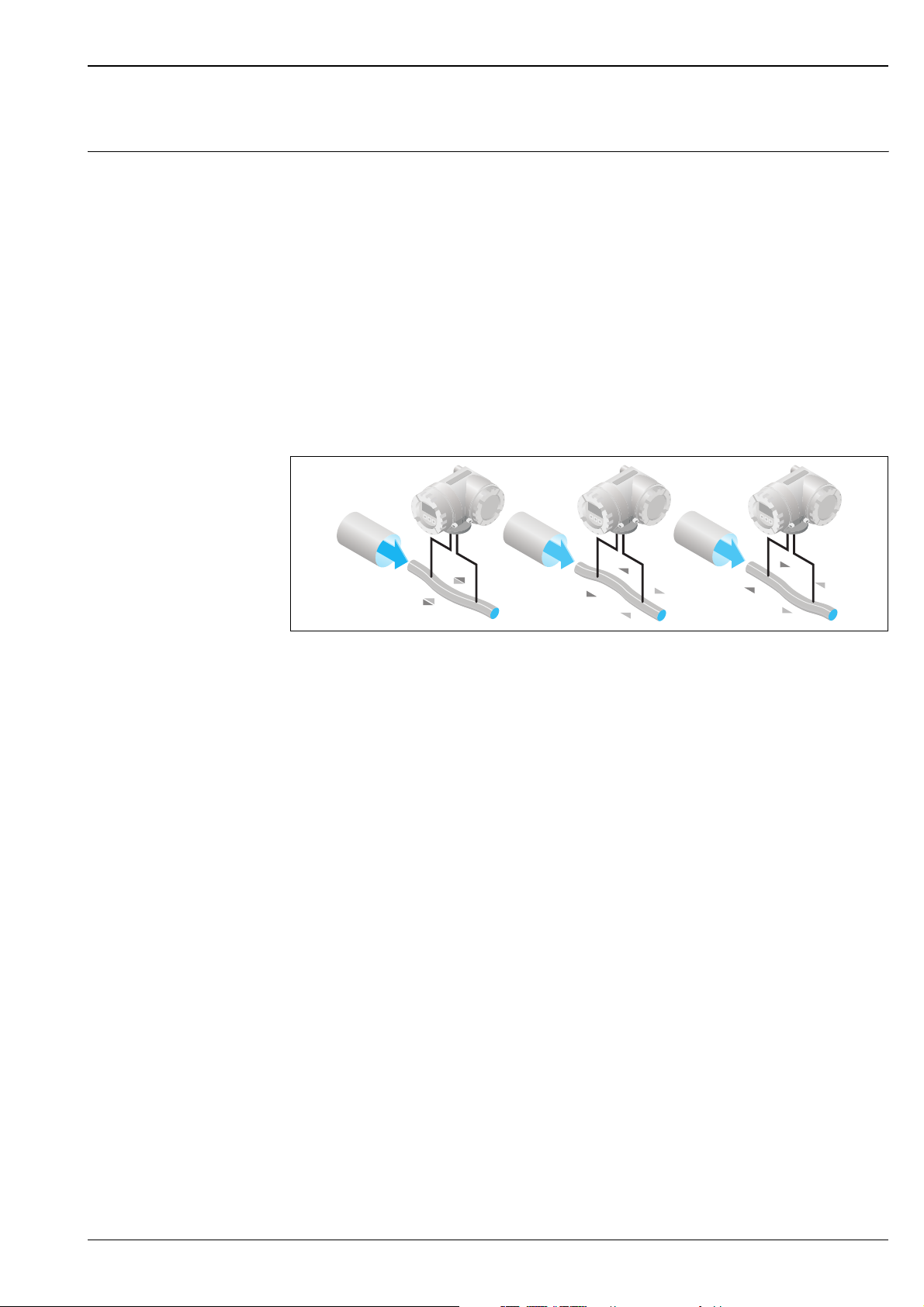
Measuring system The measuring system consists of a transmitter and a sensor. Two versions are available:
• Compact version: transmitter and sensor form a mechanical unit.
• Remote version: transmitter and sensor are mounted physically separate from one another.
Transmitter
Promass 80
Promass 83
Sensor
H
• Two-line liquid-crystal display
• Operation with push buttons
a0003671
• Four-line liquid-crystal display
• Operation with "Touch control"
• Application-specific Quick Setup
• Mass flow, volume flow, density and temperature measurement as well as
calculated variables (e.g. fluid concentrations)
a0003672
• Single bent tube. Low pressure loss and chemically
resistant material
• Nominal diameters DN 8 to 50
•Tube material: zirconium
a0003677
Documentation No.
TI 074D/06/en
Other sensors can be found in the separate documentation
A
E
• Single-tube system for highly accurate measurement of
very small flows
• Nominal diameters DN 1 to 4
• Tube material: stainless steel or Alloy C-22
a0003679
• General purpose sensor, ideal replacement for volumetric
flowmeters.
• Nominal diameters DN 8 to 50
• Tube material: stainless steel
a0002271
Documentation No.
TI 054D/06/en
Documentation No.
TI 061D/06/en
4 Endress+Hauser
Proline Promass 80H, 83H
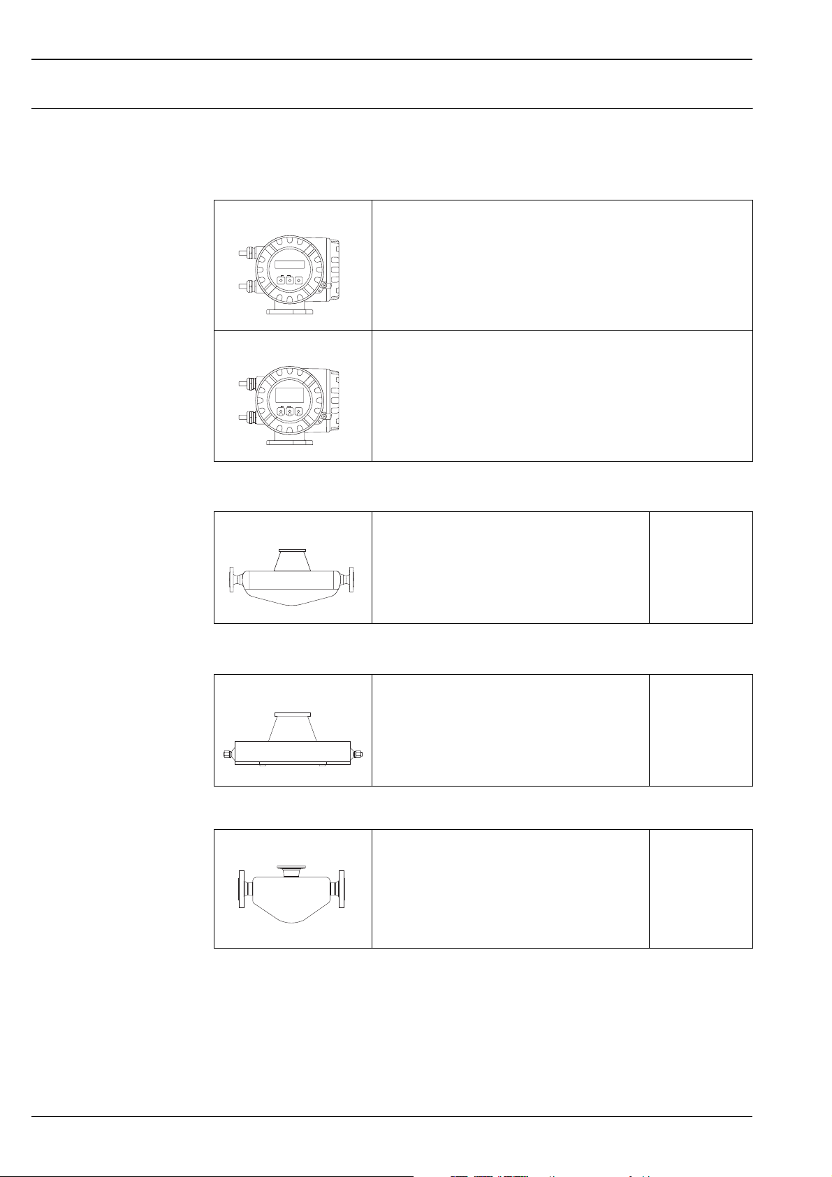
F
F (High-temperature)
M
I
• Universal sensor for fluid temperatures up to 200 °C.
• Nominal diameters DN 8 to 250
• Tube material: stainless steel or Alloy C-22
a0003673
• Universal high-temperature sensor for fluid temperatures
up to 350 °C.
• Nominal diameters DN 25, 50, 80
• Tube material: Alloy C-22
a0003675
• Robust sensor for extreme process pressures, high
requirements for the secondary containment and fluid
temperatures up to 150 °C
• Nominal diameters DN 8 to 80
• Tube material: titanium
a0003676
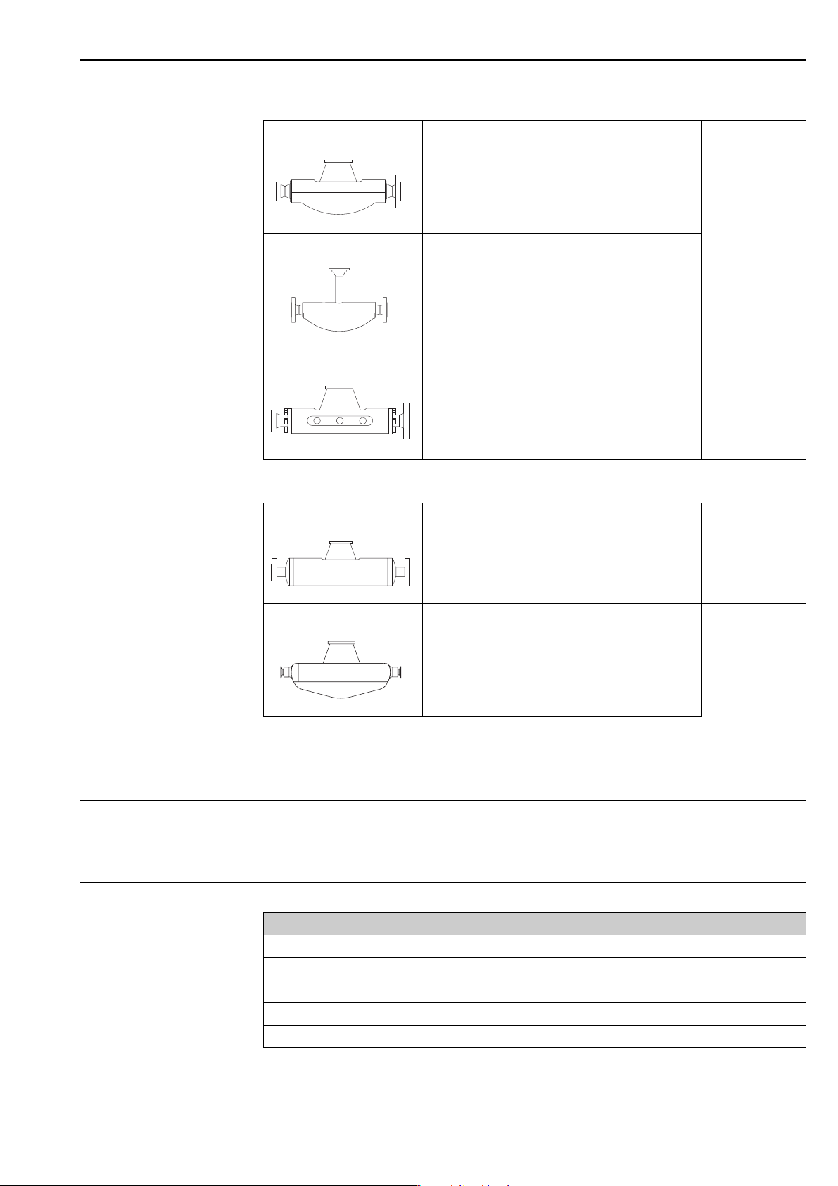
• Straight single-tube instrument. Minimal shear stress on
fluid, hygienic design, low pressure loss.
• Nominal diameters DN 8 to 80
• Tube material: titanium
Documentation No.
TI 053D/06/en
Documentation No.
TI 075D/06/en
a0003678
S
• Single bent tube.
Hygienic design, low pressure loss,
Documentation No.
TI 076D/06/en
for fluid temperatures up to 150 °C
• Nominal diameters DN 8 to 50
• Tube material: stainless steel
a0006828
Input
Measured variable • Mass flow (proportional to the phase difference between two sensors mounted on the measuring tube to
register a phase shift in the oscillation)
• Fluid density (proportional to resonance frequency of the measuring tube)
• Fluid temperature (measured with temperature sensors)
Measuring range Measuring ranges for liquids
DN Range for full scale values (liquids) g
8 0 to 2000 kg/h
15 0 to 6500 kg/h
25 0 to 18000 kg/h
40 0 to 45000 kg/h
50 0 to 70000 kg/h
min(F)
to g
max(F)
Endress+Hauser 5

Proline Promass 80H, 83H
Operable flow range Greater than 1000: 1. Flow rates above the preset full scale value do not overload the amplifier, i.e. the totalizer
values are registered correctly.
Input signal Status input (auxiliary input):
U = 3 to 30 V DC, Ri = 5 kΩ, galvanically isolated.
Configurable for: totalizer reset, positive zero return, error message reset, zero point adjustment start, batching
start/stop (optional).
Status input (auxiliary input) with PROFIBUS DP and MODBUS RS485:
U = 3 to 30 V DC, R
Switching level: 3 to 30 V DC, polarity-independent.
Configurable for: totalizer reset, positive zero return, error message reset, batching start/stop (optional), batch
totalizer reset (optional).
Current input (only Promass 83)
Active/passive selectable, galvanically isolated, resolution: 2 A
• Active: 4 to 20 mA, R
• Passive: 0/4 to 20 mA, Ri = 150 Ω, U
= 3 kΩ, galvanically isolated.
i
< 700 Ω, U
L
= 24 V DC, short-circuit proof
out
= 30 V DC
max
Output
Output signal Promass 80
Current output:
Active/passive selectable, galvanically isolated, time constant selectable (0.05 to 100 s), full scale value
selectable, temperature coefficient: typically 0.005% o.f.s./°C, resolution: 0.5 μA
• Active: 0/4 to 20 mA, R
• Passive: 4 to 20 mA; supply voltage US 18 to 30 V DC; Ri ≥ 150 Ω
Pulse/frequency output:
Passive, open collector, 30 V DC, 250 mA, galvanically isolated.
• Frequency output: full scale frequency 2 to 1000 Hz (f
• Pulse output: pulse value and pulse polarity selectable, pulse width configurable (0.5 to 2000 ms)
PROFIBUS PA interface:
• PROFIBUS PA in accordance with EN 50170 Volume 2, IEC 61158-2 (MBP), galvanically isolated
• Profile Version 3.0
• Current consumption: 11 mA
• Permitted supply voltage: 9 to 32 V
• Bus connection with integrated reverse polarity protection
• Error current FDE (Fault Disconnection Electronic) = 0 mA
• Data transmission rate: 31.25 kBit/s
• Signal encoding: Manchester II
• Function blocks: 4 x Analog Input, 1 x Totalizer
• Output data: Mass flow, Volume flow, Density, Temperature, Totalizer
• Input data: Positive zero return (ON/OFF), Zero point adjustment, Measuring mode, Totalizer control
• Bus address can be configured via miniature switches or via the local display (optional)
< 700 Ω (for HART: RL ≥ 250 Ω)
L
max
= 1250 Hz), on/off ratio 1:1, pulse width max. 2 s
6 Endress+Hauser

Proline Promass 80H, 83H
Promass 83
Current output:
Active/passive selectable, galvanically isolated, time constant selectable (0.05 to 100 s), full scale value
selectable, temperature coefficient: typically 0.005% o.f.s./°C, resolution: 0.5 μA
• Active: 0/4 to 20 mA, R
< 700 Ω (for HART: RL ≥ 250 Ω)
L
• Passive: 4 to 20 mA; supply voltage US 18 to 30 V DC; Ri ≥ 150 Ω
Pulse/frequency output:
Active/passive selectable, galvanically isolated
• Active: 24 V DC, 25 mA (max. 250 mA during 20 ms), R
> 100 Ω
L
• Passive: open collector, 30 V DC, 250 mA
• Frequency output: full scale frequency 2 to 10000 Hz (f
= 12500 Hz), on/off ratio 1:1, pulse width max.
max
2 s
• Pulse output: pulse value and pulse polarity selectable, pulse width configurable (0.05 to 2000 ms)
PROFIBUS DP interface:
• PROFIBUS DP in accordance with EN 50170 Volume 2
• Profile Version 3.0
• Data transmission rate: 9.6 kBaud to 12 MBaud
• Automatic data transmission rate recognition
• Signal encoding: NRZ Code
• Function blocks: 6 x Analog Input, 3 x Totalizer
• Output data: Mass flow, Volume flow, Corrected volume flow, Density, Reference density, Temperature,
Totalizers 1 to 3
• Input data: Positive zero return (ON/OFF), Zero point adjustment, Measuring mode, Totalizer control
• Bus address can be configured via miniature switches or via the local display (optional)
• Available output combination → Page 10
PROFIBUS PA interface:
• PROFIBUS PA in accordance with EN 50170 Volume 2, IEC 61158-2 (MBP), galvanically isolated
• Data transmission rate: 31.25 kBit/s
• Current consumption: 11 mA
• Permitted supply voltage: 9 to 32 V
• Bus connection with integrated reverse polarity protection
• Error current FDE (Fault Disconnection Electronic): 0 mA
• Signal encoding: Manchester II
• Function blocks: 6 x Analog Input, 3 x Totalizer
• Input data: Positive zero return (ON/OFF), Zero point adjustment, Measuring mode, Totalizer control
• Output data: Mass flow, Volume flow, Corrected volume flow, Density, Reference density, Temperature,
Totalizers 1 to 3
• Bus address can be configured via miniature switches or via the local display (optional)
• Available output combination → Page 10
MODBUS interface:
• MODBUS device type: slave
• Address range: 1 to 247
• Supported function codes: 03, 04, 06, 08, 16, 23
• Broadcast: supported with the function codes 06, 16, 23
• Physical interface: RS485 in accordance with EIA/TIA-485 standard
• Supported baud rate: 1200, 2400, 4 800, 9 600, 19 200, 38 400, 57600, 115200 Baud
• Transmission mode: RTU or ASCII
• Response times:
Direct data access = typically 25 to 50 ms
Auto-scan buffer (data range) = typically 3 to 5 ms
• Possible output combinations → Page 10
Endress+Hauser 7

FOUNDATION Fieldbus interface:
• FOUNDATION Fieldbus H1, IEC 61158-2, galvanically isolated
• Data transmission rate: 31.25 kBit/s
• Current consumption: 12 mA
• Permitted supply voltage: 9 to 32 V
• Error current FDE (Fault Disconnection Electronic): 0 mA
• Bus connection with integrated reverse polarity protection
• Signal encoding: Manchester II
• ITK Version 4.01
• Function blocks: 7 x Analog Input, 1 x Digital Output, 1 x PID
• Output data: Mass flow, Volume flow, Corrected volume flow, Density, Reference density, Temperature,
Totalizers 1 to 3
• Input data: Positive zero return (ON/OFF), Zero point adjustment, Measuring mode, Reset totalizer
• Link Master (LM) function is supported
Signal on alarm Current output:
Failsafe mode selectable (e.g. in accordance with NAMUR Recommendation NE 43)
Pulse/frequency output:
Failsafe mode selectable
Status output (Promass 80):
"Nonconductive" in the event of a fault or if the power supply fails
Proline Promass 80H, 83H
Relay output (Promass 83):
"Dead" in the event of a fault or if the power supply fails
Load see "Output signal"
Low flow cut off Switch points for low flow cut off are selectable.
Galvanic isolation All circuits for inputs, outputs, and power supply are galvanically isolated from each other.
Switching output Status output (Promass 80):
Open collector, max. 30 V DC / 250 mA, galvanically isolated.
Configurable for: error messages, Empty Pipe Detection (EPD), flow direction,
limit values.
Relay output (Promass 83):
Normally closed (NC or break) or normally open (NO or make) contacts available (factory setting:
relay 1 = NO, relay 2 = NC), max. 30 V / 0.5 A AC; 60 V / 0.1 A DC, galvanically isolated.
8 Endress+Hauser
Proline Promass 80H, 83H
Power supply
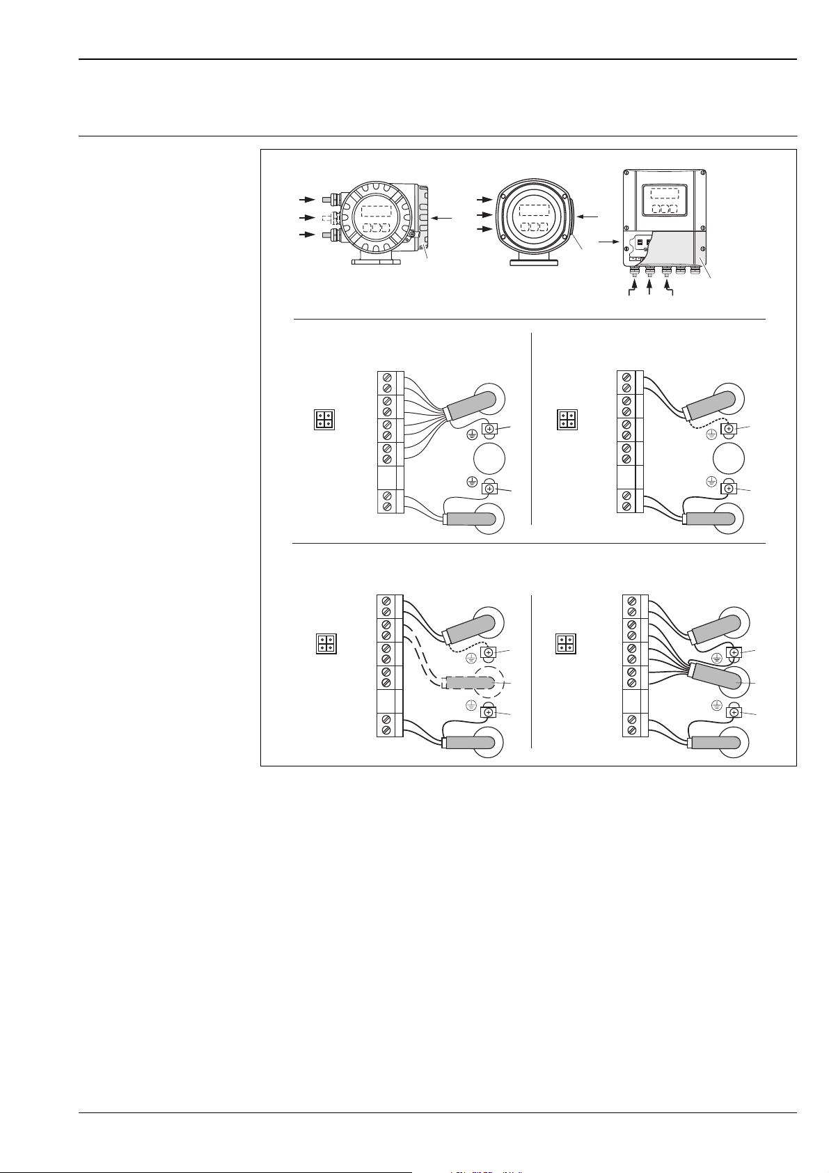
Electrical connection Measuring unit
AB
d
g
b
d
g
b
a
HART*
–27
+26
–25
f f
+24
–23
+22
–21
+20
N (L-) 2
L1 (L+)1
d
e
c
b
a
PA(–)/FF(–)
PA(+)/FF(+)
N (L-)
L1 (L+)
C
d/(g)
b
(d)
PROFIBUS PA*
FOUNDATION Fieldbus*
27
26
–
25
+
24
–
23
+
22
–
21
+
20
2
1
a
d
e
c
b
PROFIBUS DP*
PROFIBUS DP**
MODBUS RS485**
N (L-)
L1 (L+)
27
26
–
25
+
24
–
23
+
22
–
21
+
20
2
1
A (RxD/TxD-N)
B (RxD/TxD-P)
d
e
g
c
b
2
–
+
–
+
–
+
N (L-)
L1 (L+)
27
26
25
24
23
22
21
20
2
1
d
e
g
c
b
A (RxD/TxD-N)
B (RxD/TxD-P)
f f
Connecting the transmitter, cable cross-section: max. 2.5 mm
A View A (field housing)
B View B (stainless steel field housing)
C View C (wall-mount housing)
*) fixed communication board
**) flexible communication board
a Connection compartment cover
b Cable for power supply: 85 to 260 V AC, 20 to 55 V AC, 16 to 62 V DC
Terminal No. 1: L1 for AC, L+ for DC
Terminal No. 2: N for AC, L– for DC
c Ground terminal for protective ground
d Signal cable: see Terminal assignment → Page 10
Fieldbus cable:
Terminal No. 26: DP (A) / PA (+) / FF (+) / MODBUS RS485 (A) / (PA, FF: with reverse polarity protection)
Terminal No. 27: DP (B) / PA (–) / FF (–) / MODBUS RS485 (B) / (PA, FF: with reverse polarity protection)
e Ground terminal for signal cable shield / fieldbus cable / RS485 line
f Service adapter for connecting service interface FXA193 or FXA291 (Fieldcheck, ToF Tool - Fieldtool Package)
g Signal cable: see Terminal assignment → Page 10
g Cable for external termination (only for PROFIBUS DP with permanent assignment communication board):
Terminal No. 24: +5 V
Terminal No. 25: DGND
a0002441
Endress+Hauser 9

Proline Promass 80H, 83H
Electrical connection, terminal assignment
Promass 80
Terminal No. (inputs/outputs)
Order version 20 (+) / 21 (–) 22 (+) / 23 (–) 24 (+) / 25 (–) 26 (+) / 27 (–)
80***-***********A - - Frequency output Current output, HART
80***-***********D Status input Status output Frequency output Current output, HART
80***-***********H - - - PROFIBUS PA
80***-***********S - -
80***-***********T - -
80***-***********8 Status input Frequency output Current output 2 Current output 1,
Frequency output
Ex i, passive
Frequency output
Ex i, passive
Current output Ex i
Active, HART
Current output Ex i
Passive, HART
HART
Promass 83
The inputs and outputs on the communication board can be either permanently assigned (fixed) or variable
(flexible), depending on the version ordered (see table). Replacements for modules which are defective or
which have to be replaced can be ordered as accessories.
Terminal No. (inputs/outputs)
Order version 20 (+) / 21 (–) 22 (+) / 23 (–) 24 (+) / 25 (–) 26 (+) / 27 (–)
Fixed communication boards (permanent assignment)
83***-***********A - - Frequency output
83***-***********B Relay output Relay output Frequency output
83***-***********F - - - PROFIBUS PA, Ex i
83***-***********G - - -
83***-***********H - - - PROFIBUS PA
83***-***********J - - +5V (ext. termination) PROFIBUS DP
83***-***********K - -
83***–***********Q - - Status input MODBUS RS485
83***-***********R - - Current output 2
83***-***********S - -
83***-***********T - -
83***-***********U - - Current output 2
Flexible communication boards
83***-***********C Relay output 2 Relay output 1 Frequency output
83***-***********D Status input Relay output Frequency output
83***-***********E Status input Relay output Current output 2
83***-***********L Status input Relay output 2 Relay output 1
-FOUNDATION
Ex i, active
Frequency output
Ex i, passive
Frequency output
Ex i, passive
Ex i, passive
Current output
HART
Current output
HART
FOUNDATION
Fieldbus Ex i
Fieldbus
Current output 1
Ex i active, HART
Current output Ex i
Active, HART
Current output Ex i
Passive, HART
Current output 1
Ex i passive, HART
Current output
HART
Current output
HART
Current output 1
HART
Current output
HART
10 Endress+Hauser
 Loading...