

Page 1
Operating Instructions
Proline Promass 80
PROFIBUS PA
Coriolis Mass Flow Measuring System
8
BA00072D/06/EN/13.12
71197488
Valid as of version
V 3.06.XX (device software)
Page 2

Page 3

Proline Promass 80 PROFIBUS PA Table of contents
Table of contents
1 Safety instructions . . . . . . . . . . . . . . . . 5
1.1 Designated use . . . . . . . . . . . . . . . . . . . . . . . . . . . . 5
1.2 Installation, commissioning and operation . . . . . . . . 5
1.3 Operational safety . . . . . . . . . . . . . . . . . . . . . . . . . . 6
1.4 Return . . . . . . . . . . . . . . . . . . . . . . . . . . . . . . . . . . . 6
1.5 Notes on safety conventions and icons . . . . . . . . . . . 6
2 Identification . . . . . . . . . . . . . . . . . . . . 7
2.1 Device designation . . . . . . . . . . . . . . . . . . . . . . . . . 7
2.1.1 Nameplate of the transmitter . . . . . . . . . . . . 8
2.1.2 Nameplate of the sensor . . . . . . . . . . . . . . . 9
2.1.3 Nameplate for connections . . . . . . . . . . . . 10
2.2 Certificates and approvals . . . . . . . . . . . . . . . . . . . 11
2.3 Registered trademarks . . . . . . . . . . . . . . . . . . . . . . 11
3 Installation . . . . . . . . . . . . . . . . . . . . . 12
3.1 Incoming acceptance, transport and storage . . . . . . 12
3.1.1 Incoming acceptance . . . . . . . . . . . . . . . . . 12
3.1.2 Transport . . . . . . . . . . . . . . . . . . . . . . . . . 12
3.1.3 Storage . . . . . . . . . . . . . . . . . . . . . . . . . . . 13
3.2 Installation conditions . . . . . . . . . . . . . . . . . . . . . . 13
3.2.1 Dimensions . . . . . . . . . . . . . . . . . . . . . . . . 13
3.2.2 Mounting location . . . . . . . . . . . . . . . . . . . 13
3.2.3 Orientation . . . . . . . . . . . . . . . . . . . . . . . . 15
3.2.4 Special installation instructions . . . . . . . . . 17
3.2.5 Heating . . . . . . . . . . . . . . . . . . . . . . . . . . . 19
3.2.6 Thermal insulation . . . . . . . . . . . . . . . . . . 20
3.2.7 Inlet and outlet runs . . . . . . . . . . . . . . . . . 20
3.2.8 Vibrations . . . . . . . . . . . . . . . . . . . . . . . . . 20
3.2.9 Limiting flow . . . . . . . . . . . . . . . . . . . . . . . 20
3.3 Installation instructions . . . . . . . . . . . . . . . . . . . . . 21
3.3.1 Turning the transmitter housing . . . . . . . . 21
3.3.2 Installing the wall-mount housing . . . . . . . 22
3.3.3 Turning the local display . . . . . . . . . . . . . . 24
3.4 Post-installation check . . . . . . . . . . . . . . . . . . . . . . 24
4 Wiring . . . . . . . . . . . . . . . . . . . . . . . . 25
4.1 PROFIBUS PA cable specifications . . . . . . . . . . . . . 25
4.1.1 Cable type . . . . . . . . . . . . . . . . . . . . . . . . . 25
4.1.2 Maximum overall cable length . . . . . . . . . . 26
4.1.3 Maximum spur length . . . . . . . . . . . . . . . . 26
4.1.4 Number of field devices . . . . . . . . . . . . . . . 26
4.1.5 Bus termination . . . . . . . . . . . . . . . . . . . . . 26
4.1.6 Further information . . . . . . . . . . . . . . . . . . 26
4.2 Shielding and grounding . . . . . . . . . . . . . . . . . . . . 27
4.3 Connecting the remote version . . . . . . . . . . . . . . . 28
4.3.1 Connecting connecting cable for sensor/
transmitter . . . . . . . . . . . . . . . . . . . . . . . . 28
4.3.2 Cable specification for connecting cable . . . 28
4.4 Connecting the measuring unit . . . . . . . . . . . . . . . 29
4.4.1 Terminal assignment . . . . . . . . . . . . . . . . . 29
4.4.2 Transmitter connection . . . . . . . . . . . . . . . 29
4.4.3 Fieldbus connector . . . . . . . . . . . . . . . . . . 31
4.5 Degree of protection . . . . . . . . . . . . . . . . . . . . . . . 33
4.6 Post-connection check . . . . . . . . . . . . . . . . . . . . . . 34
5 Operation . . . . . . . . . . . . . . . . . . . . . . 35
5.1 Quick operation guide . . . . . . . . . . . . . . . . . . . . . . 35
5.2 Local display . . . . . . . . . . . . . . . . . . . . . . . . . . . . . 36
5.2.1 Display and operating elements . . . . . . . . . 36
5.2.2 Icons . . . . . . . . . . . . . . . . . . . . . . . . . . . . . 37
5.3 Brief operating instructions on the function matrix . 38
5.3.1 General notes . . . . . . . . . . . . . . . . . . . . . . 39
5.3.2 Enabling the programming mode . . . . . . . . 39
5.3.3 Disabling the programming mode . . . . . . . . 39
5.4 Error messages . . . . . . . . . . . . . . . . . . . . . . . . . . . . 40
5.4.1 Type of error . . . . . . . . . . . . . . . . . . . . . . . 40
5.4.2 Error message type . . . . . . . . . . . . . . . . . . . 40
5.5 Operating options . . . . . . . . . . . . . . . . . . . . . . . . . 41
5.5.1 FieldCare . . . . . . . . . . . . . . . . . . . . . . . . . . 41
5.5.2 Operating program
"SIMATIC PDM" (Siemens) . . . . . . . . . . . . 41
5.5.3 Device description files for
operating programs . . . . . . . . . . . . . . . . . . 42
5.6 PROFIBUS PA hardware settings . . . . . . . . . . . . . 43
5.6.1 Hardware write protection . . . . . . . . . . . . . 43
5.6.2 Configuring the device address . . . . . . . . . . 44
6 Commissioning . . . . . . . . . . . . . . . . . . 45
6.1 Function check . . . . . . . . . . . . . . . . . . . . . . . . . . . 45
6.2 Switching on the measuring device . . . . . . . . . . . . 45
6.3 Quick Setup . . . . . . . . . . . . . . . . . . . . . . . . . . . . . . 46
6.3.1 Quick Setup "Commissioning" . . . . . . . . . . 46
6.4 Commissioning the PROFIBUS PA interface . . . . . 47
6.5 PROFIBUS PA system integration . . . . . . . . . . . . . . 49
6.5.1 Device master file (GSD file) . . . . . . . . . . . 49
6.5.2 Selecting the GSD file in the
measuring device . . . . . . . . . . . . . . . . . . . . 51
6.5.3 Maximum numbers of writes . . . . . . . . . . 51
6.6 Cyclic data transmission PROFIBUS PA . . . . . . . . . 52
6.6.1 Block model . . . . . . . . . . . . . . . . . . . . . . . 52
6.6.2 Modules for cyclic data transmission . . . . . 52
6.6.3 Description of the modules . . . . . . . . . . . . 53
6.6.4 Configuration examples with
Simatic S7 HW-Konfig . . . . . . . . . . . . . . . . 59
6.7 Adjustment . . . . . . . . . . . . . . . . . . . . . . . . . . . . . . 61
6.7.1 Zero point adjustment . . . . . . . . . . . . . . . . 61
6.7.2 Density adjustment . . . . . . . . . . . . . . . . . . 63
6.8 Rupture disk . . . . . . . . . . . . . . . . . . . . . . . . . . . . . 64
6.9 Purge and pressure monitoring connections . . . . . . 64
6.10 Data storage device (HistoROM) . . . . . . . . . . . . . . 64
6.10.1 HistoROM/S–DAT (sensor–DAT) . . . . . . . 64
7 Maintenance . . . . . . . . . . . . . . . . . . . . 65
7.1 Exterior cleaning . . . . . . . . . . . . . . . . . . . . . . . . . . 65
7.2 Cleaning with pigs (Promass H, I, S, P) . . . . . . . . . . 65
7.3 Replacing seals . . . . . . . . . . . . . . . . . . . . . . . . . . . . 65
Endress+Hauser 3
Page 4

Proline Promass 80 PROFIBUS PA Table of contents
8 Accessories . . . . . . . . . . . . . . . . . . . . . 66
8.1 Device-specific accessories . . . . . . . . . . . . . . . . . . . 66
8.2 Measuring principle-specific accessories . . . . . . . . . 66
8.3 Service-specific accessories . . . . . . . . . . . . . . . . . . 67
9 Troubleshooting . . . . . . . . . . . . . . . . . 68
9.1 Troubleshooting instructions . . . . . . . . . . . . . . . . . 68
9.2 System error messages . . . . . . . . . . . . . . . . . . . . . . 70
9.2.1 Displaying the device status on
PROFIBUS PA . . . . . . . . . . . . . . . . . . . . . 70
9.2.2 List of system error messages . . . . . . . . . . 71
9.3 Process error messages . . . . . . . . . . . . . . . . . . . . . . 76
9.3.1 Displaying the device status on
PROFIBUS PA . . . . . . . . . . . . . . . . . . . . . . 76
9.3.2 List of process error messages . . . . . . . . . . 76
9.4 Process errors without messages . . . . . . . . . . . . . . 78
9.5 Spare parts . . . . . . . . . . . . . . . . . . . . . . . . . . . . . . 79
9.5.1 Removing and installing printed
circuit boards . . . . . . . . . . . . . . . . . . . . . . . 80
9.5.2 Replacing the device fuse . . . . . . . . . . . . . . 84
9.6 Return . . . . . . . . . . . . . . . . . . . . . . . . . . . . . . . . . . 85
9.7 Disposal . . . . . . . . . . . . . . . . . . . . . . . . . . . . . . . . 85
9.8 Software history . . . . . . . . . . . . . . . . . . . . . . . . . . 85
10 Technical data . . . . . . . . . . . . . . . . . . . 87
10.1 Technical data at a glance . . . . . . . . . . . . . . . . . . . 87
10.1.1 Applications . . . . . . . . . . . . . . . . . . . . . . . . 87
10.1.2 Function and system design . . . . . . . . . . . . 87
10.1.3 Input . . . . . . . . . . . . . . . . . . . . . . . . . . . . . 87
10.1.4 Output . . . . . . . . . . . . . . . . . . . . . . . . . . . 90
10.1.5 Power supply . . . . . . . . . . . . . . . . . . . . . . . 91
10.1.6 Performance characteristics . . . . . . . . . . . . 92
10.1.7 Installation . . . . . . . . . . . . . . . . . . . . . . . 108
10.1.8 Environment . . . . . . . . . . . . . . . . . . . . . . 108
10.1.9 Process . . . . . . . . . . . . . . . . . . . . . . . . . . 109
10.1.10 Mechanical construction . . . . . . . . . . . . . 118
10.1.11 Human interface . . . . . . . . . . . . . . . . . . . 123
10.1.12 Certificates and approvals . . . . . . . . . . . . 123
10.1.13 Ordering information . . . . . . . . . . . . . . . 124
10.1.14 Accessories . . . . . . . . . . . . . . . . . . . . . . . 124
10.1.15 Supplementary Documentation . . . . . . . . 124
Index . . . . . . . . . . . . . . . . . . . . . . . . . . . . . 125
4 Endress+Hauser
Page 5

Proline Promass 80 PROFIBUS PA Safety instructions
1 Safety instructions
1.1 Designated use
The measuring device described in these Operating Instructions is to be used only for measuring the
mass flow rate of liquids and gases. At the same time, the system also measures fluid density and
fluid temperature. These parameters are then used to calculate other variables such as volume flow.
Fluids with widely differing properties can be measured.
Examples:
• Chocolate, condensed milk, liquid sugar
• Oils, fats
• Acids, alkalis, lacquers, paints, solvents and cleaning agents
• Pharmaceuticals, catalysts, inhibitors, suspensions
• Gases, liquefied gases, etc.
Resulting from incorrect use or from use other than that designated the operational safety of the
measuring devices can be suspended. The manufacturer accepts no liability for damages being
produced from this.
1.2 Installation, commissioning and operation
Note the following points:
• Installation, connection to the electricity supply, commissioning and maintenance of the device
must be carried out by trained, qualified specialists authorized to perform such work by the
facility's owner-operator. The specialist must have read and understood these Operating
Instructions and must follow the instructions they contain.
• The device must be operated by persons authorized and trained by the facility's owner-operator.
Strict compliance with the instructions in the Operating Instructions is mandatory.
• Endress+Hauser is willing to assist in clarifying the chemical resistance properties of parts wetted
by special fluids, including fluids used for cleaning. However small changes in temperature,
concentration or the degree of contamination in the process can result in changes of the chemical
resistance properties. Therefore, Endress+Hauser can not guarantee or accept liability for the
chemical resistance properties of the fluid wetted materials in a specific application. The user is
responsible for the choice of fluid wetted materials in regards to their in-process resistance to
corrosion.
• If carrying out welding work on the piping, the welding unit may not be grounded by means of
the measuring device.
• The installer must ensure that the measuring system is correctly wired in accordance with the
wiring diagrams. The transmitter must be grounded, except in cases where
special protective measures have been taken, e.g. galvanically isolated power supply SELV
or PELV (SELV = Save Extra Low Voltage; PELV = Protective Extra Low Voltage).
• Invariably, local regulations governing the opening and repair of electrical devices apply.
Endress+Hauser 5
Page 6

Safety instructions Proline Promass 80 PROFIBUS PA
1.3 Operational safety
Note the following points:
• Measuring systems for use in hazardous environments are accompanied by separate
"Ex documentation", which is an integral part of these Operating Instructions. Strict compliance
with the installation instructions and ratings as stated in this supplementary documentation is
mandatory.
The symbol on the front of this supplementary Ex documentation indicates the approval and the
certification body (e.g. 0 Europe, 2 USA, 1 Canada).
• The measuring device complies with the general safety requirements in accordance with
EN 61010-1, the EMC requirements of IEC/EN 61326, and NAMUR recommendation NE 21,
NE 43 and NE 53.
• For measuring systems used in SIL 2 applications, the separate manual on functional safety must
be observed.
• Due to the performance rate in the electronic components, the maximum heating of the outer
housing surfaces is 10 K. When hot media are passed through the measuring tube, the surface
temperature of the housing increases. With regard to the sensor, in particular, you should expect
temperatures that can be close to the temperature of the medium. If the temperature of the
medium is high, ensure staff are protected against burns and scalds.
• The manufacturer reserves the right to modify technical data without prior notice. Your
Endress+Hauser distributor will supply you with current information and updates to this
Operating Instructions.
#
"
1.4 Return
• Do not return a measuring device if you are not absolutely certain that all traces of hazardous
substances have been removed, e.g. substances which have penetrated crevices or diffused
through plastic.
• Costs incurred for waste disposal and injury (burns, etc.) due to inadequate cleaning will be
charged to the owner-operator.
• Please note the measures on ä 85
1.5 Notes on safety conventions and icons
The devices are designed to meet state-of-the-art safety requirements, have been tested, and left the
factory in a condition in which they are safe to operate. The devices comply with the applicable
standards and regulations in accordance with EN 61010-1 "Protection Measures for Electrical
Equipment for Measurement, Control, Regulation and Laboratory Procedures". The devices can,
however, be a source of danger if used incorrectly or for anything other than the designated use.
Consequently, always pay particular attention to the safety instructions indicated in these Operating
Instructions by the following icons:
Warning!
"Warning" indicates an action or procedure which, if not performed correctly, can result in injury
or a safety hazard. Comply strictly with the instructions and proceed with care.
Caution!
"Caution" indicates an action or procedure which, if not performed correctly, can result in incorrect
operation or destruction of the device. Comply strictly with the instructions.
!
6 Endress+Hauser
Note!
"Note" indicates an action or procedure which, if not performed correctly, can have an indirect
effect on operation or trigger an unexpected response on the part of the device.
Page 7

Proline Promass 80 PROFIBUS PA Identification
2 Identification
The following options are available for identification of the measuring device::
• Nameplate specifications
• Order code with breakdown of the device features on the delivery note
• Enter serial numbers from nameplates in W@M Device Viewer
(www.endress.com/deviceviewer): All information about the measuring device is displayed.
For an overview of the scope of the Technical Documentation provided, refer to the following:
• The chapters "Supplementary Documentation" ä 124
•Der W@M Device Viewer: Enter the serial number from the nameplate
(www.endress.com/deviceviewer)
Reorder
The measuring device is reordered using the order code.
Extended order code:
• The device type (product root) and basic specifications (mandatory features) are always listed.
• Of the optional specifications (optional features), only the safety and approval-related
specifications are listed (e.g. LA). If other optional specifications are also ordered, these are
indicated collectively using the # placeholder symbol (e.g. #LA#).
• If the ordered optional specifications do not include any safety and approval-related specifications,
they are indicated by the + placeholder symbol (e.g. 8E2B50-ABCDE+).
2.1 Device designation
The "Promass 80" flow measuring system consists of the following components:
• Promass 80 transmitter.
• Promass F, Promass E, Promass A, Promass H, Promass I, Promass S or Promass P sensor.
Two versions are available:
• Compact version: transmitter and sensor form a single mechanical unit.
• Remote version: transmitter and sensor are installed separately.
Endress+Hauser 7
Page 8
Identification Proline Promass 80 PROFIBUS PA
Order Code:
Ser. no.:
Ext. ord. cd.:
i
1
5
6
7
8
2
3
4
10 11
13
12
9
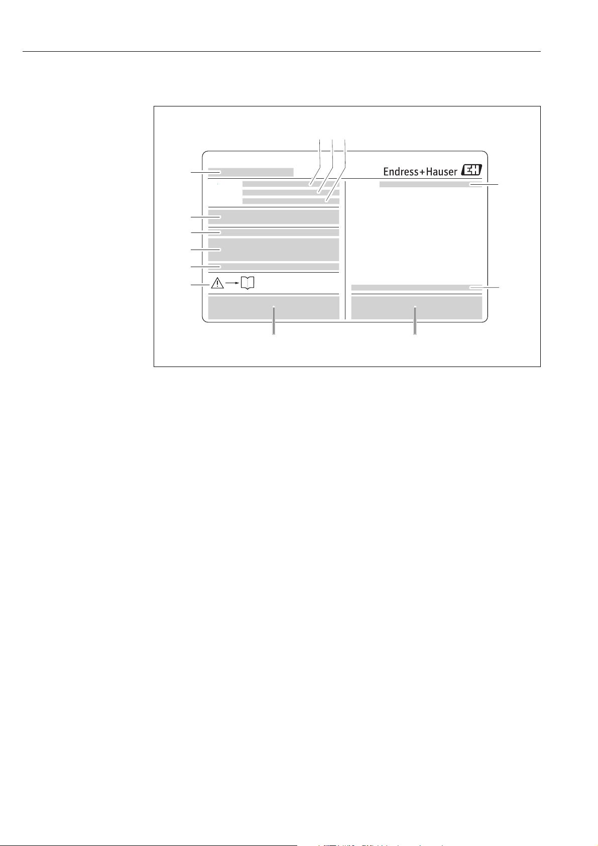
2.1.1 Nameplate of the transmitter
Fig. 1: Example of a transmitter nameplate
1 Name of the transmitter
2 Order code
3 Serial number (Ser. no.)
4 Extended order code (Ext. ord. cd.)
5 Power supply, frequency and power consumption
6 Additional function and software
7 Available inputs / outputs
8Reserved for information on special products
9 Please refer to operating instructions / documentation
10 Reserved for certificates, approvals and for additional information on device version
11 Patents
12 Degree of protection
13 Ambient temperature range
A0015928
8 Endress+Hauser
Page 9
Proline Promass 80 PROFIBUS PA Identification
i
14
16
17
18
1
9
11
19
10
15
13
12
8
6
7
Size:
K-factor:
Tm:
Materials:
Density cal.:
Ser.No.:
Order Code:
5
4
3
2
Ext. ord. cd.:
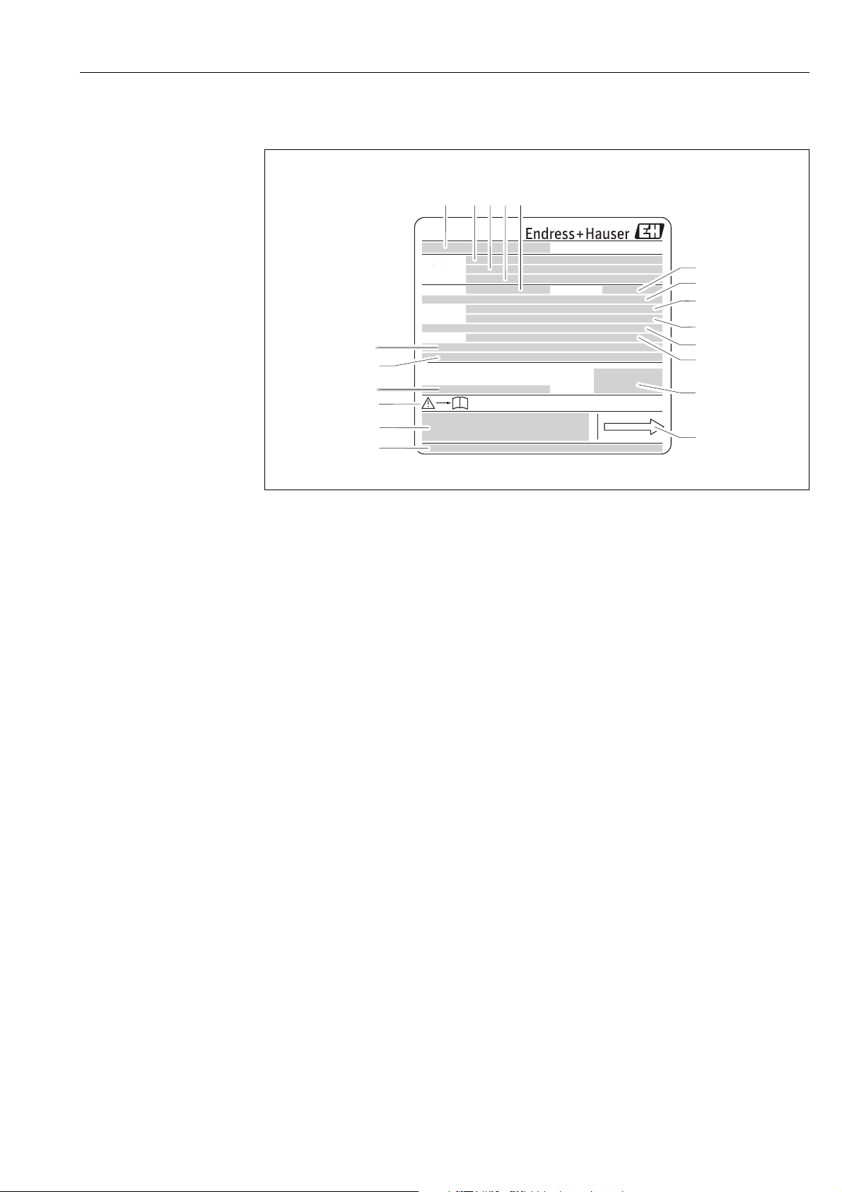
2.1.2 Nameplate of the sensor
Fig. 2: Example of a sensor nameplate
1 Name of the sensor
2 Order code
3 Serial number (Ser. no.)
4 Extended order code (Ext. ord. cd.)
5 Calibration factor with zero point (K-factor)
6 Nominal diameter device (Size)
7 Flange nominal diameter/Nominal pressure
8 Material of measuring tubes (Materials)
9 Max. fluid temperature (Tm)
10 Pressure range of secondary containment
11 Accuracy of density measurement (Density cal.)
12 Additional information
13 Reserved for information on special products
14 Ambient temperature range
15 Degree of protection
16 Please refer to operating instructions / documentation
17 Reserved for additional information on device version (approvals, certificates)
18 Patents
19 Flow direction
A0015930
Endress+Hauser 9
Page 10
Identification Proline Promass 80 PROFIBUS PA
4
7
2
3
8 1210 11
1
9
6
26(+) / 27(-)
NC:
Versorgung /
Tension d'alimentation
Observer manuel d'instruction
See operating manual
Betriebsanleitung beachten
Communication:
Drivers:
Device SW:
Ser.No.:
Supply /
24(+) / 25(-)
22(+) / 23(-)
20(+) / 21(-)
N/LPE
A:
NO:
P:
L1/L+
12
319475-00XX
active
passive
normally open contact
normally closed contact
Date:
Update 1
ex works / ab Werk / réglages usine
Update 2
5
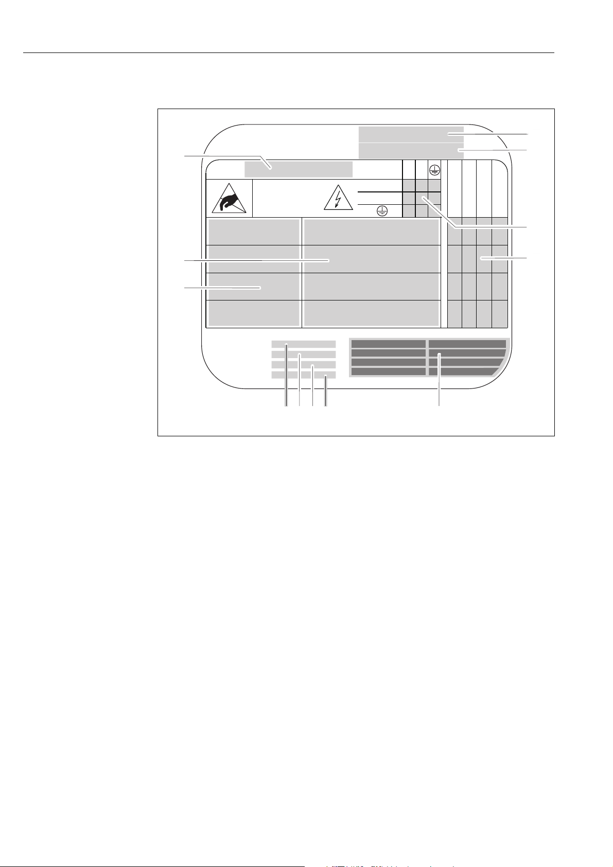
2.1.3 Nameplate for connections
A0015931
Fig. 3: Example of a connection nameplate
1 Serial number (Ser. no.)
2 Possible inputs and outputs
3 Signals present at inputs and outputs
4 Possible configuration of current output
5 Possible configuration of relay contacts
6 Terminal assignment, cable for power supply
7 Terminal assignment and configuration (see point 4 and 5) of inputs and outputs
8 Version of device software currently installed (Device SW)
9 Installed communication type (Communication)
10 Information on current communication software (Drivers: Device Revision and Device Description),
11 Date of installation (Date)
12 Current updates to data specified in points 8 to 11 (Update1, Update 2)
10 Endress+Hauser
Page 11

Proline Promass 80 PROFIBUS PA Identification
2.2 Certificates and approvals
The devices are designed in accordance with good engineering practice to meet state-of-the-art
safety requirements, have been tested, and left the factory in a condition in which they are safe to
operate.
The devices comply with the applicable standards and regulations in accordance with EN 61010-1
"Protection Measures for Electrical Equipment for Measurement, Control, Regulation and
Laboratory Procedures" and with the EMC requirements of IEC/EN 61326.
The measuring system described in these Operating Instructions thus complies with the statutory
requirements of the EC Directives. Endress+Hauser confirms successful testing of the device by
affixing to it the CE mark.
The measuring system complies with the EMC requirements of the "Australian Communications
and Media Authority (ACMA)".
The flowmeter has successfully passed all the test procedures carried out and is certified and
registered by the PNO (PROFIBUS User Organization).
The device thus meets all the requirements of the following specifications:
• Certified to PROFIBUS Specification Profile 3.0 version
(Device certification number: provided upon request)
• The measuring device can also be operated with certified devices of other manufacturers
(interoperability).
2.3 Registered trademarks
KALREZ® and VITON
Registered trademarks of E.I. Du Pont de Nemours & Co., Wilmington, USA
TRI-CLAMP
®
Registered trademark of Ladish & Co., Inc., Kenosha, USA
SWAGELOK
®
Registered trademark of Swagelok & Co., Solon, USA
PROFIBUS
®
Registered trademark of the PROFIBUS User Organization, Karlsruhe, D
HistoROM™, S-DAT
Registered or registration-pending trademarks of Endress+Hauser Flowtec AG, Reinach, CH
®
®
, FieldCare®, Fieldcheck®, Applicator
®
Endress+Hauser 11
Page 12
Installation Proline Promass 80 PROFIBUS PA
3 Installation
3.1 Incoming acceptance, transport and storage
3.1.1 Incoming acceptance
On receipt of the goods, check the following points:
• Check the packaging and the contents for damage.
• Check the shipment, make sure nothing is missing and that the scope of supply matches your
order.
3.1.2 Transport
The following instructions apply to unpacking and to transporting the device to its final location:
• Transport the devices in the containers in which they are delivered.
• The covers or caps fitted to the process connections prevent mechanical damage to the sealing
faces and the ingress of foreign matter to the measuring tube during transportation and storage.
Consequently, do not remove these covers or caps until immediately before installation.
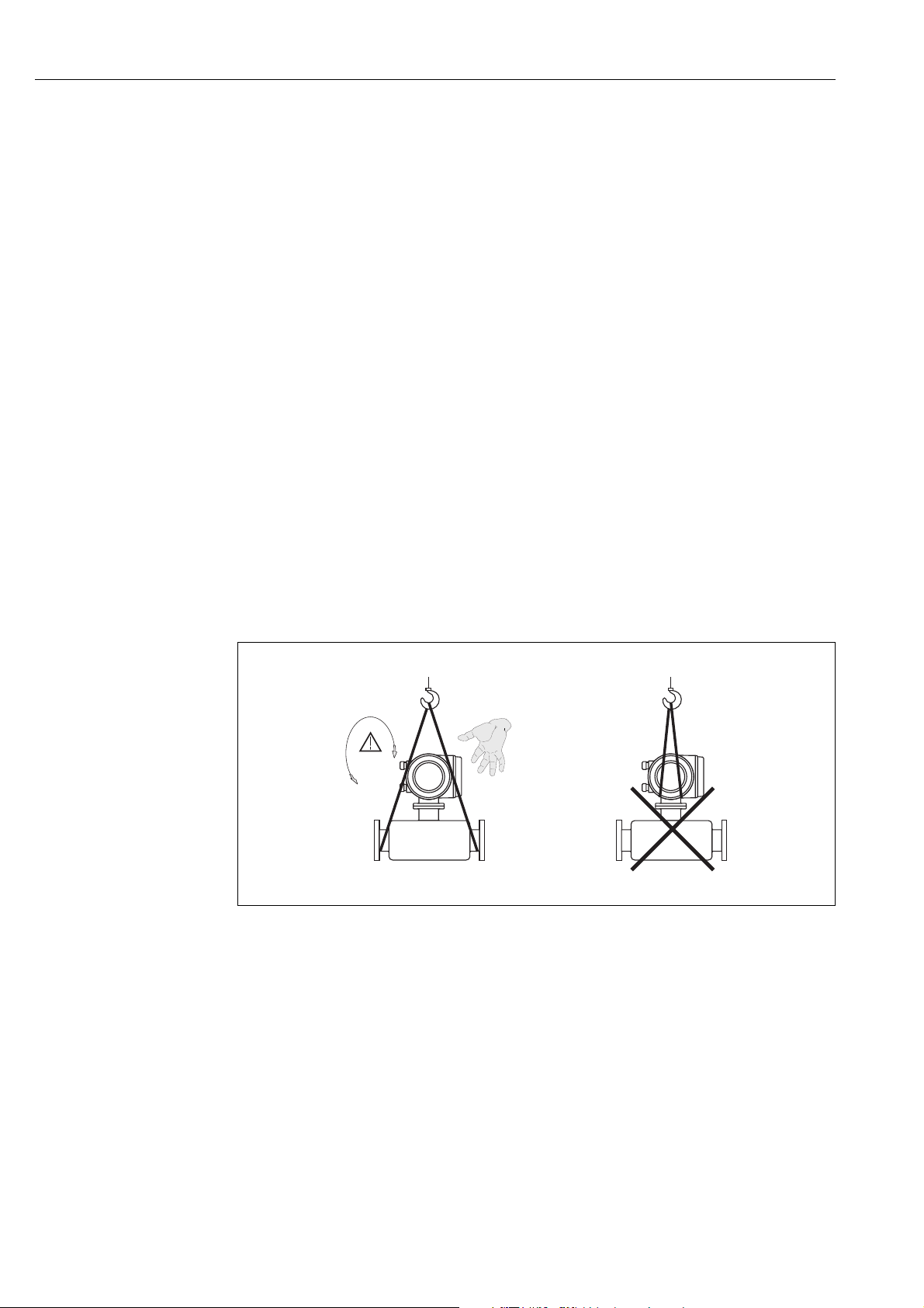
• Do not lift measuring devices of nominal diameters > DN 40 (> 1½") by the transmitter housing
or the connection housing in the case of the remote version (å 4). - Use webbing slings slung
round the two process connections. Do not use chains, as they could damage the housing.
#
Warning!
Risk of injury if the measuring device slips. The center of gravity of the assembled measuring device
might be higher than the points around which the slings are slung.
At all times, therefore, make sure that the device does not unexpectedly turn around its axis or slip.
a0004294
Fig. 4: Instructions for transporting sensors with > DN 40 (> 1½")
12 Endress+Hauser
Page 13
Proline Promass 80 PROFIBUS PA Installation
3.1.3 Storage
Note the following points:
• Pack the measuring device in such a way as to protect it reliably against impact for storage (and
transportation). The original packaging provides optimum protection.
• The permissible storage temperature is –40 to +80 °C (–40 °F to +176 °F), preferably +20 °C
(+68 °F).
• Do not remove the protective covers or caps on the process connections until you are ready to
install the device.
• The measuring device must be protected against direct sunlight during storage in order to avoid
unacceptably high surface temperatures.
3.2 Installation conditions
Note the following points:
• No special measures such as supports are necessary. External forces are absorbed by the
construction of the instrument, for example the secondary containment.
• The high oscillation frequency of the measuring tubes ensures that the correct operation of the
measuring system is not influenced by pipe vibrations.
• No special precautions need to be taken for fittings which create turbulence (valves, elbows,
T-pieces, etc.), as long as no cavitation occurs.
• For mechanical reasons and in order to protect the pipe, it is advisable to support heavy sensors.
3.2.1 Dimensions
All the dimensions and lengths of the sensor and transmitter are provided in the separate
documentation "Technical Information"
3.2.2 Mounting location
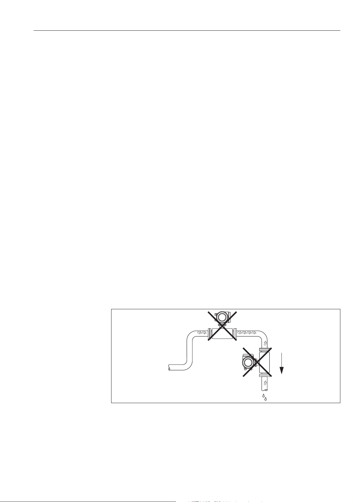
Entrained air or gas bubbles forming in the measuring tube can result in an increase in measuring
errors.
Avoid the following locations in the pipe installation:
• Highest point of a pipeline. Risk of air accumulating.
• Directly upstream of a free pipe outlet in a vertical pipeline.
a0003605
Fig. 5: Mounting location
Endress+Hauser 13
Page 14
Installation Proline Promass 80 PROFIBUS PA
1
2
3
4
5
Installation in a vertical pipe
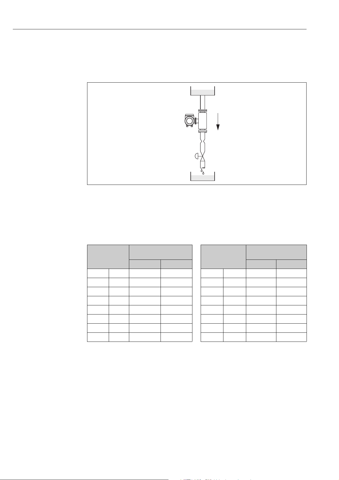
The proposed configuration in the following diagram, however, permits installation in a vertical
pipeline. Pipe restrictors or the use of an orifice plate with a smaller cross-section than the nominal
diameter prevent the sensor from running empty during measurement.
a0003597
Fig. 6: Installation in a vertical pipe (e.g. for batching applications)
1 Supply tank
2Sensor
3 Orifice plate, pipe restrictions (see Table)
4Valve
5 Batching tank
Ø Orifice plate, pipe
restrictor
DN
1 1/24" 0.8 0.03 40 1½" 22 0.87
2 1/12" 1.5 0.06 40 FB 1½" 35 1.38
4 1/8" 3.0 0.12 50 2" 28 1.10
8 3/8" 6 0.24 50 FB 2" 54 2.00
15 ½" 10 0.40 80 3" 50 2.00
15 FB ½" 15 0.60 100 4" 65 2.60
25 1" 14 0.55 150 6" 90 3.54
25 FB 1" 24 0.95 250 10" 150 5.91
FB = Full bore versions of Promass I
mm inch mm inch
DN
Ø Orifice plate, pipe
restrictor
System pressure
It is important to ensure that cavitation does not occur, because it would influence the oscillation
of the measuring tube. No special measures need to be taken for fluids which have properties similar
to water under normal conditions.
In the case of liquids with a low boiling point (hydrocarbons, solvents, liquefied gases) or in suction
lines, it is important to ensure that pressure does not drop below the vapor pressure and that the
liquid does not start to boil. It is also important to ensure that the gases that occur naturally in many
liquids do not outgas. Such effects can be prevented when system pressure is sufficiently high.
For this reason, the following installation locations are preferred:
• Downstream from pumps (no danger of vacuum)
• At the lowest point in a vertical pipe.
14 Endress+Hauser
Page 15
Proline Promass 80 PROFIBUS PA Installation
10 mm
4 x
3.2.3 Orientation
Make sure that the direction of the arrow on the nameplate of the sensor matches the direction of
flow direction in which the fluid flows through the pipe.
Orientation Promass A
Vertical
Recommended orientation with direction of flow upwards. When fluid is not flowing, entrained
solids will sink down and gases
be completely drained and protected against solids build-up.
Horizontal
When installation is correct the transmitter housing
gas bubbles or solids deposits can form in the bent measuring tube (single-tube system).
will rise away from the measuring tube. The measuring tubes can
is above or
below the pipe. This means that no
Special installation instructions for Promass A
Caution!
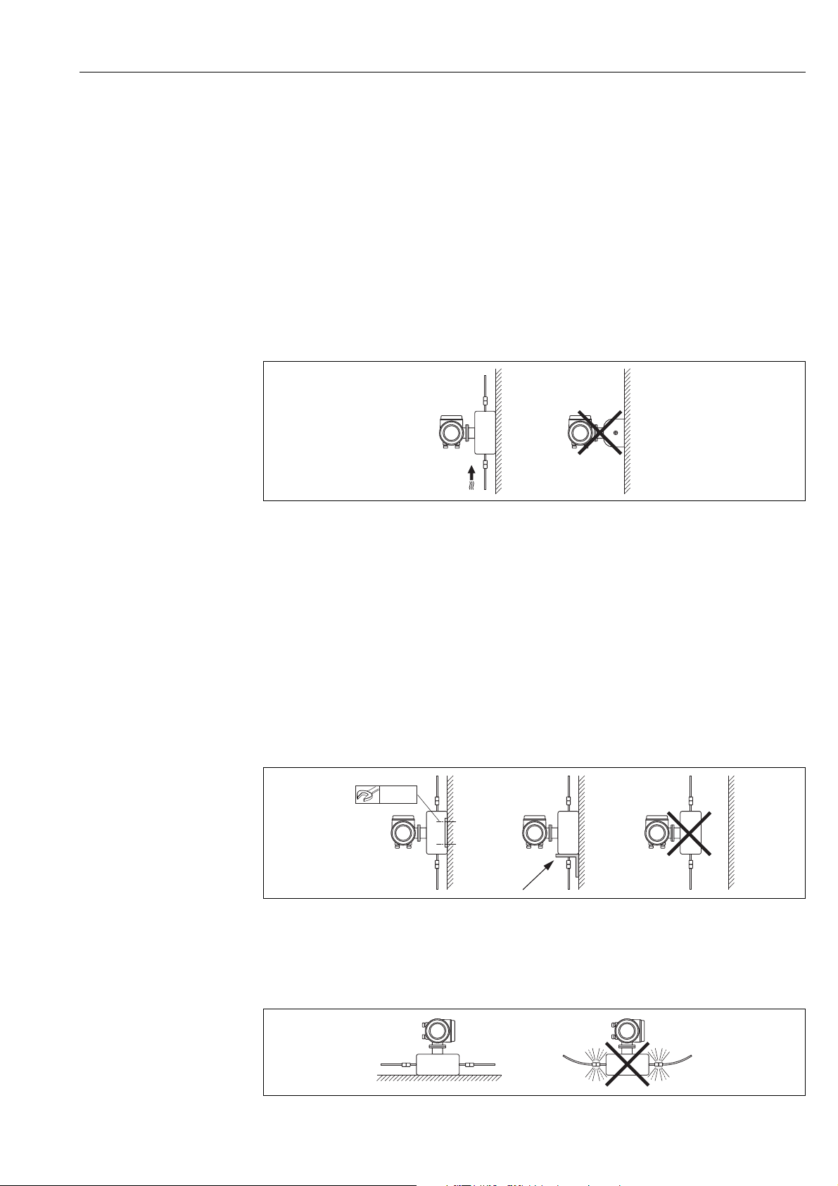
"
Risk of measuring pipe fracture if sensor installed incorrectly!
The sensor may not be installed in a pipe as a freely suspended sensor:
• Using the base plate, mount the sensor directly on the floor, the wall or the ceiling.
• Support the sensor on a firmly mounted support base (e.g. angle bracket).
Vertical
We recommend two installation ve
rsions when mounti
ng vertically:
• Mounted directly on a wall using the base plate
• Measuring device supported on an angle bracket mounted on the wall
A0018978
A0018980
Horizontal
We recommend the following installation version when mounting horizontally:
• Measuring device standing on a firm support base
Endress+Hauser 15
A0018979
Page 16
Installation Proline Promass 80 PROFIBUS PA
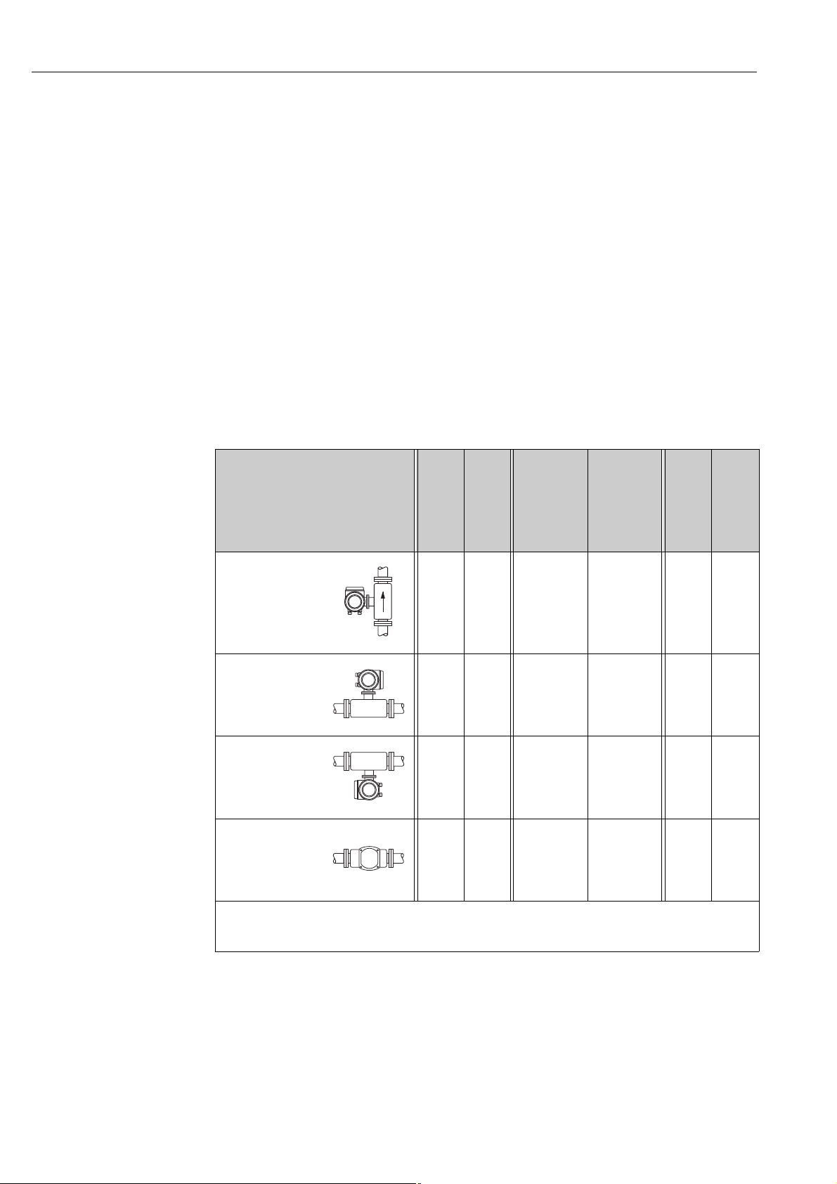
Orientation Promass F, E, H, I, S, P
Make sure that the direction of the arrow on the nameplate of the sensor matches the direction of
flow (direction in which the fluid flows through the pipe).
Vertical:
Recommended orientation with upward direction of flow (Fig. V). When fluid is not flowing,
entrained solids will sink down and gases will rise away from the measuring tube. The measuring
tubes can be completely drained and protected against solids buildup.
Horizontal (Promass F, E):
The measuring tubes of Promass F and E must be horizontal and beside each other. When
installation is correct the transmitter housing is above or below the pipe (Fig. H1/H2). Always avoid
having the transmitter housing in the same horizontal plane as the pipe.
Horizontal (Promass H, I, S, P):
Promass H, I, S and P can be installed in any orientation in a horizontal pipe run.
Fig. V:
Vertical orientation
a0004572
Fig. H1:
Horizontal
orientation
Transmitter head up
Fig. H2:
Horizontal
orientation
Transmitter head
down
Fig. H3:
Horizontal
orientation
Transmitter head to
the side
= Recommended orientation
ÐÐ
= Orientation recommended in certain situations
Ð
✘ = Impermissible orientation
a0004576
a0004580
a0007558
Promass F, E
Standard, compact
Promass F, E
Standard, remote
Promass F
High-temperature,
compact
✔✔ ✔✔ ✔✔ ✔✔ ✔✔ ✔✔
✔✔ ✔✔✘TM > 200 °C
( 392 °F)
✔✔ ✔✔ ✔✔ ✔✔ ✔✔ ✔✔
✘ ✘ ✘ ✘ ✔✔ ✔✔
Promass F
High-temperature,
remote
Ð
TM > 200 °C
( 392 °F)
Promass H, I, S, P
Standard, compact
Promass H, I, S, P
✔✔ ✔✔
Standard, compact
In order to ensure that the permissible ambient temperature range for the transmitter (ä 108)
is not exceeded, we recommend the following orientations:
• For fluids with very high temperatures we recommend the horizontal orientation with the
transmitter head pointing downwards (Fig. H2) or the vertical orientation (Fig. V).
• For fluids with very low temperatures, we recommend the horizontal orientation with the
transmitter head pointing upwards (Fig. H1) or the vertical orientation (Fig. V).
16 Endress+Hauser
Page 17
Proline Promass 80 PROFIBUS PA Installation
1
2
1
2
3
21 mm/m (¼ in/ft) ~2%
3.2.4 Special installation instructions
Promass F, E, H, S and P
Caution!
"
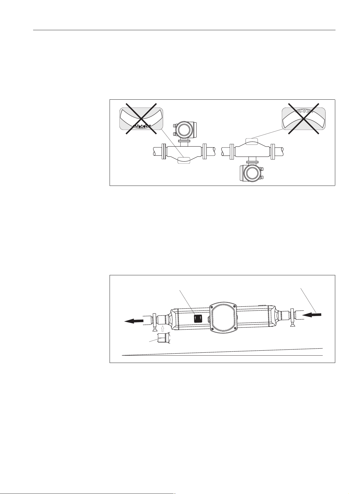
If the measuring tube is curved and the unit is installed horizontally, adapt the sensor position to
the fluid properties.
a0004581
Fig. 7: Horizontal installation of sensors with curved measuring tube.
1 Not suitable for fluids with entrained solids. Risk of solids accumulating.
2 Not suitable for outgassing fluids. Risk of air accumulating.
Promass I and P with Eccentric Tri-clamps
Eccentric Tri-Clamps can be used to ensure complete drainability when the sensor is installed in a
horizontal line. When lines are pitched in a specific direction and at a specific slope, gravity can be
used to achieve complete drainability. The sensor must be installed in the correct position with the
tube bend facing to the side, to ensure full drainability in the horizontal position. Markings on the
sensor show the correct mounting position to optimize drainability.
a0007396
Fig. 8: Promass P: When lines are pitched in a specific direction and at a specific slope: as per hygienic guidelines
(21 mm/m or approximatley 2%). Gravity can be used to achieve complete drainability.
1 The arrow indicates the direction of flow (direction of fluid flow through the pipe).
2 The label shows the installation orientation for horizontal drainability.
3 The underside of the process connection is indicated by a scribed line. This line indicates the lowest point of the
eccentric process connection.
Endress+Hauser 17
Page 18
Installation Proline Promass 80 PROFIBUS PA
EscEsc
E
-
+
1
2
3
21 mm/m ( 2%)~
0.83 in/3.28 ft ( 2%)~0.83 in/3.28 ft ( 2%)~
A
B
C
A0010011
Fig. 9: Promass I: When lines are pitched in a specific direction and at a specific slope: as per hygienic guidelines
(21 mm/m or approximatley 2%). Gravity can be used to achieve complete drainability.
1 The arrow indicates the direction of flow (direction of fluid flow through the pipe).
2 The label shows the installation orientation for horizontal drainability.
3 The underside of the process connection is indicated by a scribed line. This line indicates the lowest point of the
eccentric process connection.
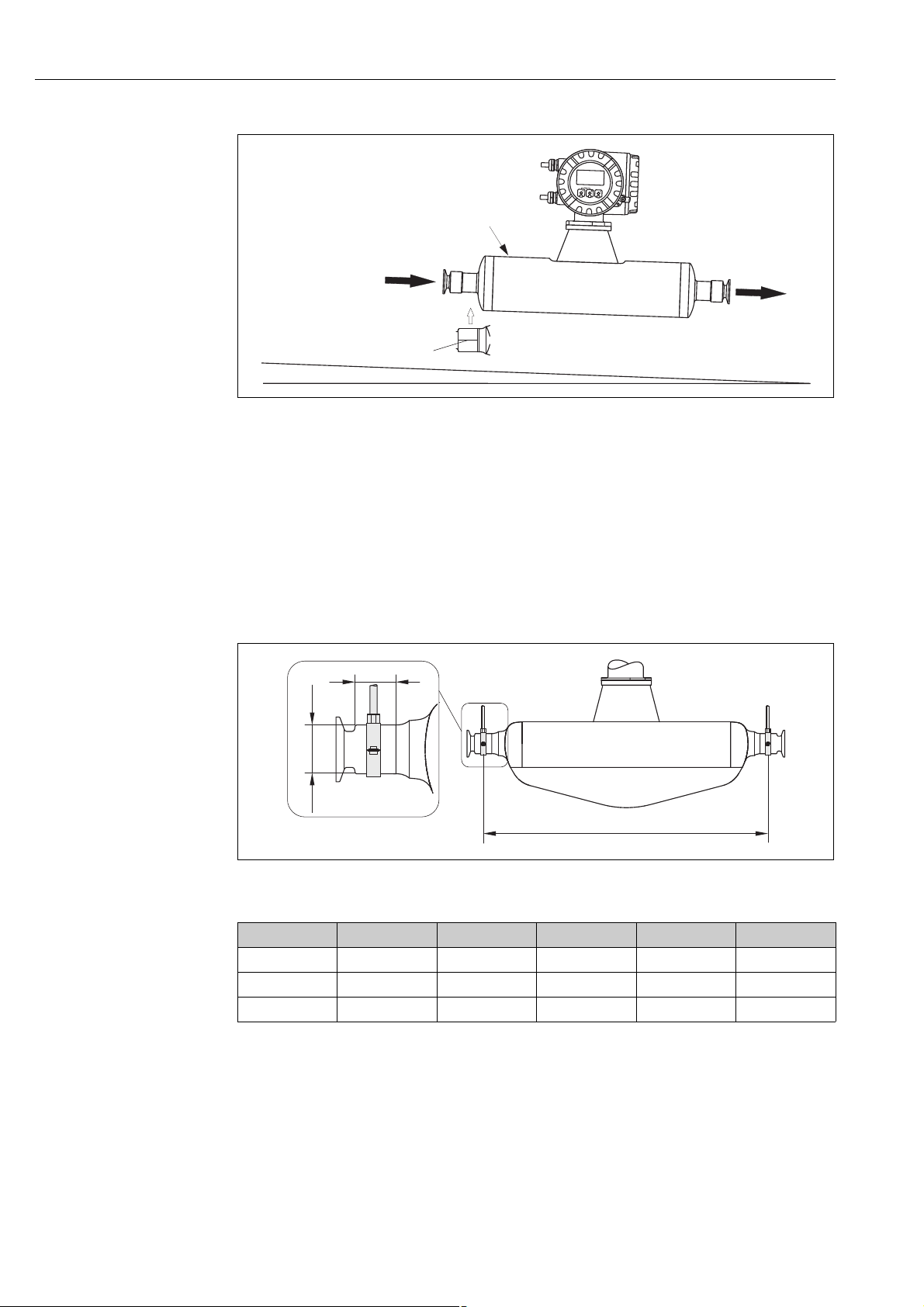
Promass P and I with hygienic connections
(mounting clamp with lining between clamp and instrument)
It is not necessary to support the sensor under any circumstances for operational performance. If the
requirement exists to support the sensor the following recommendation should be followed.
A0007397
Fig. 10: Promass P, mounted with mounting clamp
DN 8 15 25 40 50
A 298 402 542 750 1019
B 33 33 33 36.5 44.1
C 2828385675
18 Endress+Hauser
Page 19
Proline Promass 80 PROFIBUS PA Installation
Esc
E
-
+
1
2
3
21 mm/m ( 2%)~
0.83 in/3.28 ft ( 2%)~0.83 in/3.28 ft ( 2%)~
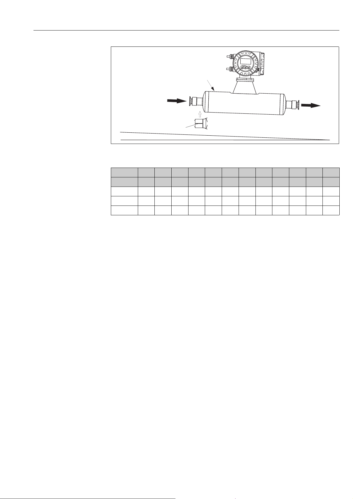
A0010008
Fig. 11: Promass I, mounted with mounting clamp
DN 8 15 15FB 25 25FB 40 40FB 50 50FB 50FB 80 80
Tri-Clamp ½" 3/4" 1" 1" 1 ½" 1 ½" 2" 2" 2 ½" 3" 2 ½" 3"
A 373 409 539 539 668 668 780 780 1152 1152 1152 1152
B 202030302828353557575757
C 404044.544.56060808090909090
3.2.5 Heating
Some fluids require suitable measures to avoid loss of heat at the sensor. Heating can be electric,
e.g. with heated elements, or by means of hot water or steam pipes made of copper or heating
jackets.
Caution!
"
• Risk of electronics overheating! Make sure that the maximum permissible ambient temperature
for the transmitter is not exceeded. Consequently, make sure that the adapter between sensor and
transmitter and the connection housing of the remote version always remain free of insulating
material. Note that a certain orientation might be required, depending on the fluid temperature
ä 15.
• With a fluid temperature between 200 °C to 350 °C (392 to 662 °F) the remote version of the
high-temperature version is preferable.
• When using electrical heat tracing whose heat is regulated using phase control or by pulse packs,
it cannot be ruled out that the measured values are influenced by magnetic fields which may
occur, (i.e. at values greater than those permitted by the EC standard (Sinus 30 A/m)). In such
cases, the sensor must be magnetically shielded.
The secondary containment can be shielded with tin plates or electric sheets without privileged
direction (e.g. V330-35A) with the following properties:
– Relative magnetic permeability μ
– Plate thickness d 0.35 mm (0.014")
• Information on permissible temperature ranges ä 109
Special heating jackets which can be ordered as accessories from Endress+Hauser are available for
the sensors.
300
r
Endress+Hauser 19
Page 20
Installation Proline Promass 80 PROFIBUS PA
mm (inch)
max. 60 (2.4)
Esc
E
-
+
max. 60 (2.4)
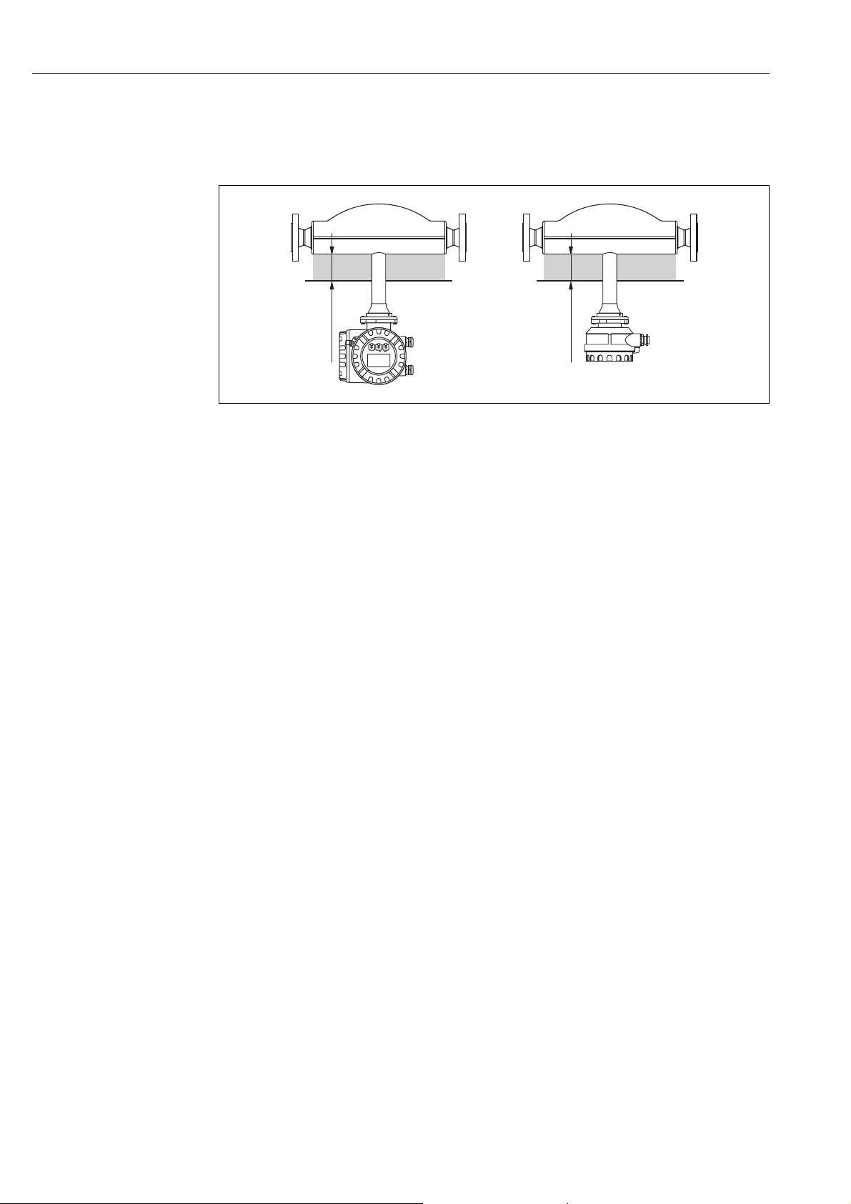
3.2.6 Thermal insulation
Some fluids require suitable measures to avoid loss of heat at the sensor. A wide range of materials
can be used to provide the required thermal insulation.
a0004614
Fig. 12: In the case of the Promass F high-temperature version, a maximum insulation thickness of 60 mm (2.4") must
be observed in the area of the electronics/neck.
If the device is installed horizontally (with transmitter head pointing upwards), an insulation
thickness of min. 10 mm (0.4") is recommended to reduce convection. The maximum insulation
thickness of 60 mm (2.4") must be observed.
3.2.7 Inlet and outlet runs
There are no installation requirements regarding inlet and outlet runs. If possible, install the sensor
well clear of fittings such as valves, T-pieces, elbows, etc.
3.2.8 Vibrations
The high oscillation frequency of the measuring tubes ensures that the correct operation of the
measuring system is not influenced by pipe vibrations. Consequently, the sensors require no special
measures for attachment.
3.2.9 Limiting flow
Relevant information can be found in the "Technical Data" section under "Measuring range"
ä 87 or "Limiting flow" ä 110.
20 Endress+Hauser
Page 21
Proline Promass 80 PROFIBUS PA Installation
3
5
6
1
2
4
1
2
3
4
5
3.3 Installation instructions
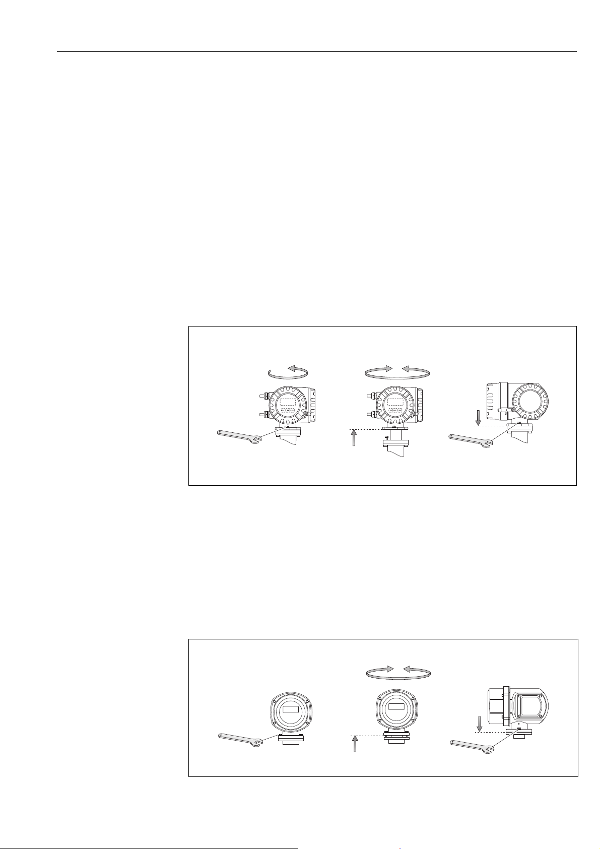
3.3.1 Turning the transmitter housing
Turning the aluminum field housing
#
Warning!
The turning mechanism in devices with EEx d/de or FM/CSA Cl. I Div. 1 classification is not the
same as that described here. The procedure for turning these housings is described in the Ex-specific
documentation.
1. Loosen the two securing screws.
2. Turn the bayonet catch as far as it will go.
3. Carefully lift the transmitter housing as far as it will go.
4. Turn the transmitter housing to the desired position (max. 2 × 90° in either direction).
5. Lower the housing into position and reengage the bayonet catch.
6. Retighten the two securing screws.
a0004302
Fig. 13: Turning the transmitter housing (aluminum field housing)
Turning the stainless steel field housing
1. Loosen the two securing screws.
2. Carefully lift the transmitter housing as far as it will go.
3. Turn the transmitter housing to the desired position (max. 2 × 90° in either direction).
4. Lower the housing into position.
5. Retighten the two securing screws.
Endress+Hauser 21
Fig. 14: Turning the transmitter housing (stainless steel field housing)
a0004303
Page 22
Installation Proline Promass 80 PROFIBUS PA
a
b
c
c
90 (3.54)
35 (1.38)
192 (7.56)
81.5(3.2)
mm (inch)
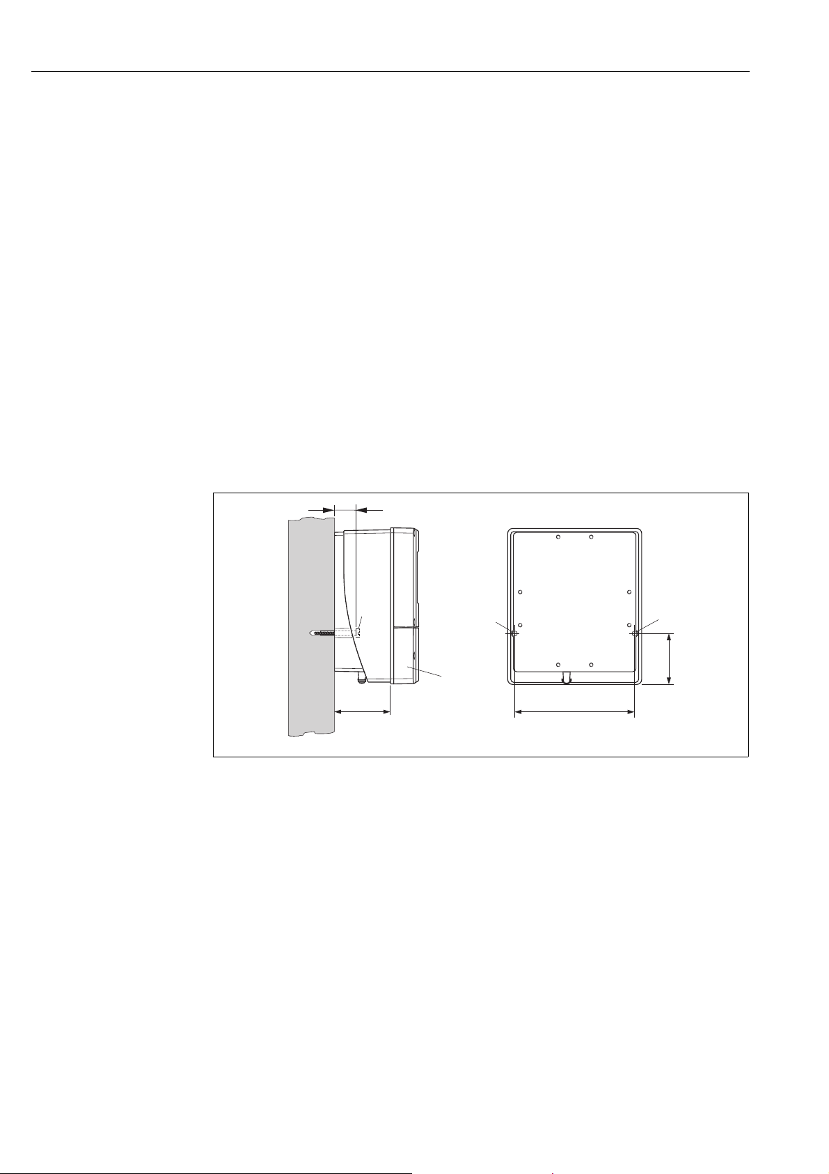
3.3.2 Installing the wall-mount housing
There are various ways of installing the wall-mount housing:
• Mounted directly on the wall
• Installation in control panel (separate mounting set, accessories) ä 23
• Pipe mounting (separate mounting set, accessories) ä 23
Caution!
"
• At the mounting location, make sure that the ambient temperature does not go beyond the
permissible range (ä 108). Install the device in a shady location. Avoid direct sunlight.
• Always install the wall-mount housing in such a way that the cable entries are pointing down.
Mounted directly on the wall
1. Drill the holes as illustrated in the diagram.
2. Remove the cover of the connection compartment (a).
3. Push the two securing screws (b) through the appropriate bores (c) in the housing.
– Securing screws (M6): max. Ø 6.5 mm (0.26")
– Screw head: max. Ø 10.5 mm (0.41")
4. Secure the transmitter housing to the wall as indicated.
5. Screw the cover of the connection compartment (a) firmly onto the housing.
a0001130
Fig. 15: Mounted directly on the wall
22 Endress+Hauser
Page 23
Proline Promass 80 PROFIBUS PA Installation
245 (9.65)
~110 (~4.33)
210 (8.27)
+0.5 (+0.019)
–0.5 (–0.019)
+0.5 (+0.019)
–0.5 (–0.019)
mm (inch)
Ø 20…70
(Ø 0.79…2.75)
~ ~ 6.1)155 (
mm (inch)
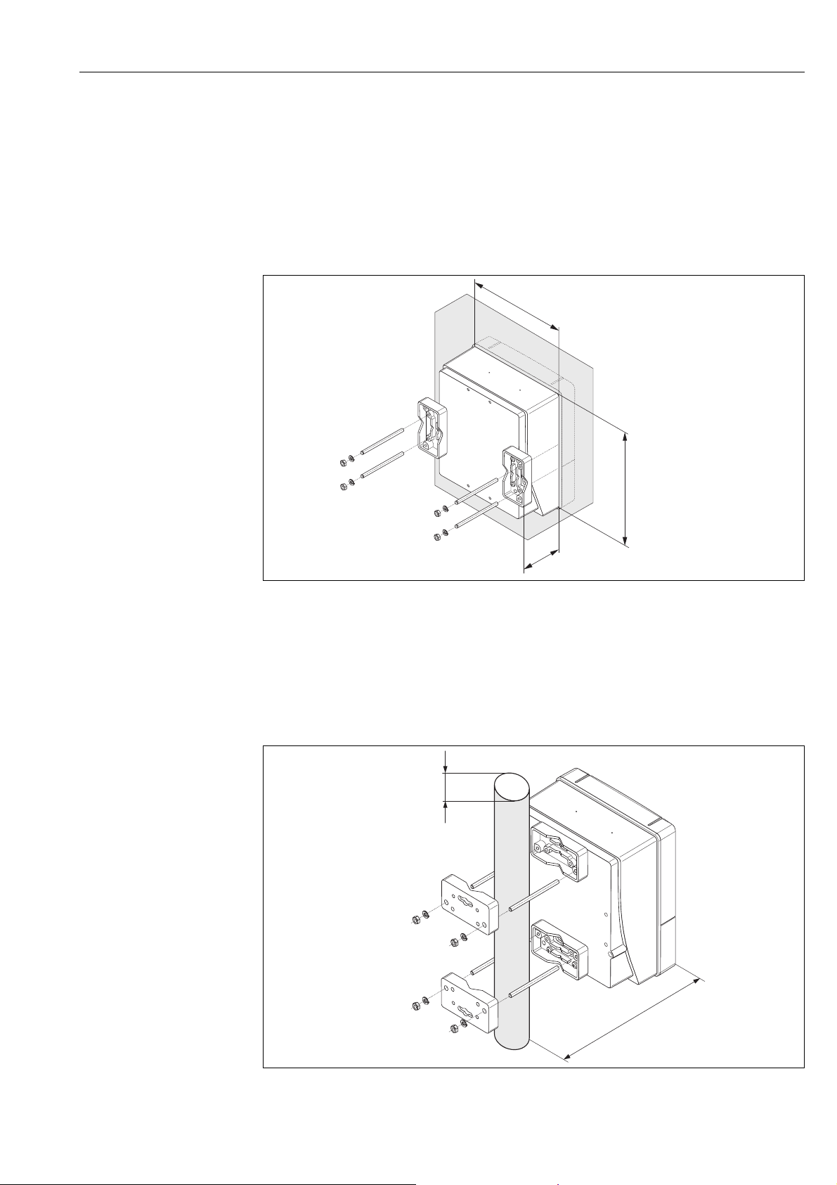
Panel mounting
1. Prepare the opening in the panel as illustrated in the diagram.
2. Slide the housing into the opening in the panel from the front.
3. Screw the fasteners onto the wall-mount housing.
4. Screw threaded rods into holders and tighten
until the housing is solidly seated on the panel wall. Afterwards, tighten the locking nuts.
Additional support is not necessary.
Fig. 16: Panel installation (wall-mount housing)
Pipe mounting
The assembly should be performed by following the instructions in the diagram.
Caution!
"
If a warm pipe is used for installation, make sure
that the housing temperature does not exceed the max. permitted value of +60 °C (+140 °F).
a0001131
a0001132
Fig. 17: Pipe mounting (wall-mount housing)
Endress+Hauser 23
Page 24
Installation Proline Promass 80 PROFIBUS PA
4 x 45°
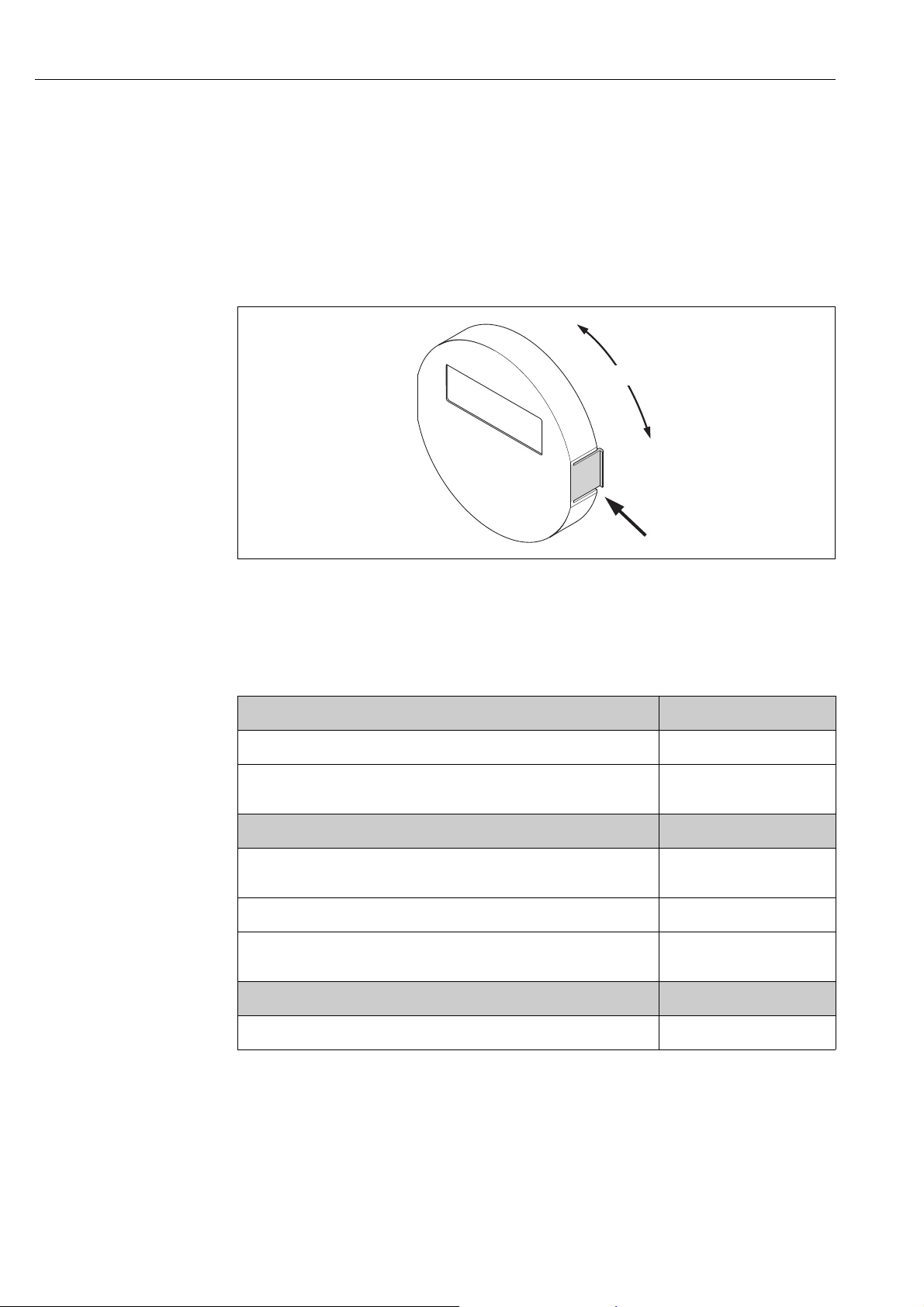
3.3.3 Turning the local display
1. Unscrew cover of the electronics compartment from the transmitter housing.
2. Press the side latches on the display module and remove the module from the electronics
compartment cover plate.
3. Rotate the display to the desired position (max. 4 × 45 ° in both directions), and reset it onto
the electronics compartment cover plate.
4. Screw the cover of the electronics compartment firmly back onto the transmitter housing.
Fig. 18: Turning the local display (field housing)
3.4 Post-installation check
Perform the following checks after installing the measuring device in the pipe:
Device condition and specifications Notes
Is the device damaged (visual inspection)? -
Does the device correspond to specifications at the measuring point, including
process temperature and pressure, ambient temperature, measuring range, etc.?
Installation Notes
Does the arrow on the sensor nameplate match the direction of flow through the
pipe?
Are the measuring point number and labeling correct (visual inspection)? -
Is the orientation chosen for the sensor correct, in other words suitable for sensor
type, fluid properties (outgassing, with entrained solids) and fluid temperature?
Process environment / process conditions Notes
ä 5
-
ä 13
a0003236
Is the measuring device protected against moisture and direct sunlight? -
24 Endress+Hauser
Page 25
Proline Promass 80 PROFIBUS PA Wiring
4 Wiring
#
!
Warning!
When connecting Ex-certified devices, see the notes and diagrams in the Ex-specific supplement to
these Operating Instructions. Please do not hesitate to contact your Endress+Hauser sales office if
you have any questions.
Note!
The device does not have an internal power switch. For this reason, assign the device a switch or
power-circuit breaker which can be used to disconnect the power supply line from the power grid.
4.1 PROFIBUS PA cable specifications
4.1.1 Cable type
Twin-core cables are recommended for connecting the device to the fieldbus. Following
IEC 61158-2 (MBP), four different cable types (A, B, C, D) can be used with the fieldbus, only two
of which (cable types A and B) are shielded.
• Cable types A or B are particularly preferable for new installations. Only these types have cable
shielding that guarantees adequate protection from electromagnetic interference and thus the
most reliable data transfer. In the case of type B multi-pair cables, it is permissible to operate
multiple fieldbuses with the same degree of protection on one cable. No other circuits are
permissible in the same cable.
• Practical experience has shown that cable types C and D should not be used due to the lack of
shielding, since the freedom from interference generally does not meet the requirements
described in the standard.
The electrical data of the fieldbus cable have not been specified but determine important
characteristics of the design of the fieldbus, such as distances bridged, number of users,
electromagnetic compatibility, etc.
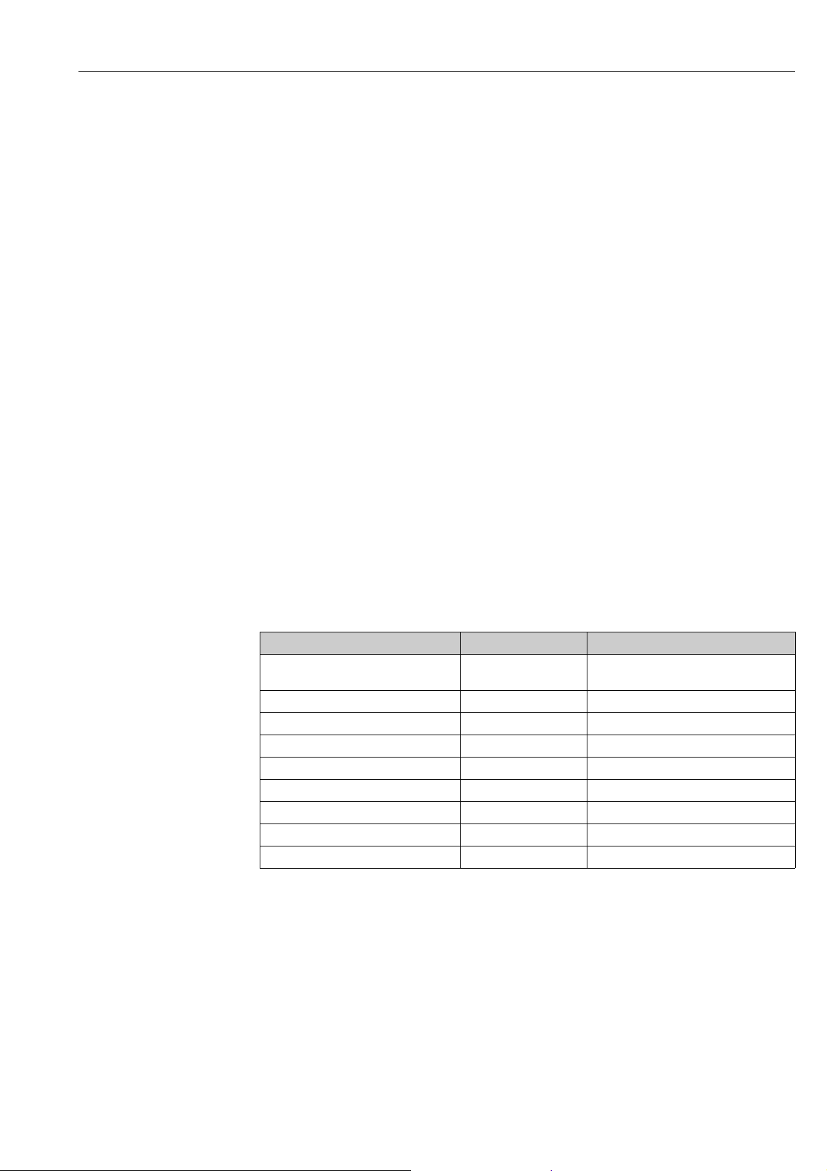
Type A Type B
Cable structure Twisted pair,
shielded
Wire cross-section 0.8 mm
Loop-resistance (DC) 44 /km 112 /km
Characteristic impedance at 31.25 kHz 100 ± 20% 100 ± 30%
Attenuation constant at 39 kHz 3 dB/km 5 dB/km
Capacitive asymmetry 2 nF/km 2 nF/km
Envelope delay distortion (7.9 to 39 kHz) 1.7 s/km *
Shield coverage 90% *
Max. cable length (incl. spurs >1 m) 1900 m (6 200 ft) 1200 m (4 000 ft)
* Not specified
Suitable fieldbus cables from various manufacturers for non-hazardous areas are listed below:
• Siemens: 6XV1 830-5BH10
• Belden: 3076F
• Kerpen: CeL-PE/OSCR/PVC/FRLA FB-02YS(ST)YFL
(AWG 18) 0.32 mm (AWG 22)
One or more twisted pairs, fully shielded
Endress+Hauser 25
Page 26
Wiring Proline Promass 80 PROFIBUS PA
4.1.2 Maximum overall cable length
The maximum network expansion depends on the type of protection and the cable specifications.
The overall cable length combines the length of the main cable and the length of all the spurs
>1 m (>3.28 ft).
Note the following points:
• The maximum permissible overall cable length depends on the cable type used:
Type A 1 900 m 6 200 ft
Type B 1 200 m 4 000 ft
• If repeaters are used, the maximum permissible cable length is doubled.
A maximum of three repeaters are permitted between user and master.
4.1.3 Maximum spur length
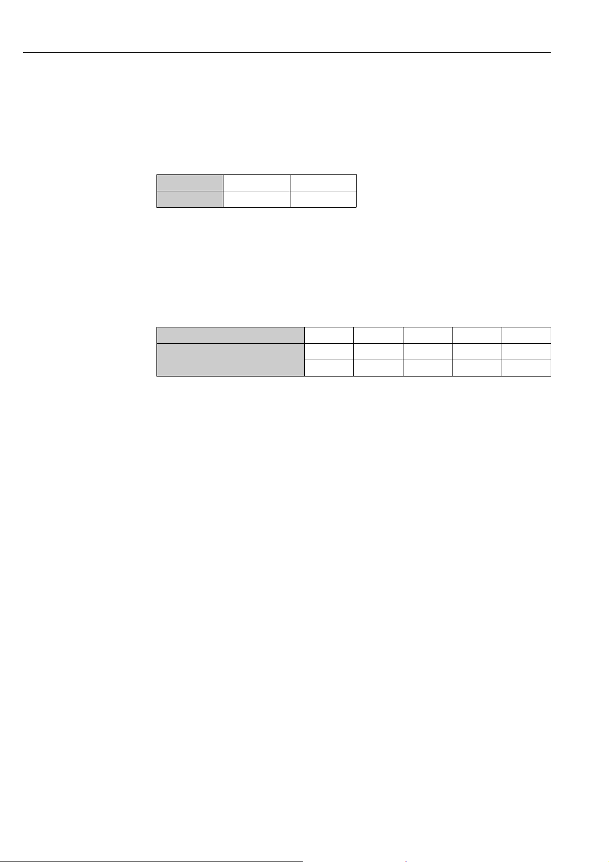
The line between the distribution box and field device is described as a spur. In the case of non-Ex
applications, the max. length of a spur depends on the number of spurs >1 m (>3.28 ft):
Number of spurs 1 to 12 13 to 14 15 to 18 19 to 24 25 to 32
Max. length per spur
[m] 120 90 60 30 1
[ft] 393 295 196 98 3.28
4.1.4 Number of field devices
In systems that meet FISCO with EEx ia type of protection, the line length is limited to
max. 1 000 m (3 280 ft). A maximum of 32 users per segment in non-Ex areas or a maximum of
10 users in an Ex-area (EEx ia IIC) is possible. The actual number of users must be determined
during configuration.
4.1.5 Bus termination
The start and end of each fieldbus segment are always to be terminated with a bus terminator.
With various junction boxes (non-Ex), the bus termination can be activated via a switch.
If this is not the case, a separate bus terminator must be installed.
Note the following points:
• In the case of a branched bus segment, the device furthest from the segment coupler represents
the end of the bus.
• If the fieldbus is extended with a repeater then the extension must also be terminated at both
ends.
4.1.6 Further information
General information and further notes regarding the wiring are contained in BA034S/04:
"Guidelines for planning and commissioning, PROFIBUS DP/PA, field communication."
26 Endress+Hauser
Page 27

Proline Promass 80 PROFIBUS PA Wiring
4.2 Shielding and grounding
When planning the shielding and grounding for a fieldbus system, there are three important points
to consider:
• Electromagnetic compatibility (EMC)
• Explosion protection
• Safety of the personnel
To ensure the optimum electromagnetic compatibility of systems, it is important that the system
components and above all the cables, which connect the components, are shielded and that no
portion of the system is unshielded. Ideally, the cable shields are connected to the normally metal
housings of the connected field devices. Since these are generally connected to the protective earth,
the shield of the bus cable is grounded many times. Keep the stripped and twisted lengths of cable
shield to the terminals as short as possible.
This approach, which provides the best electromagnetic compatibility and personal safety, can be
used without restriction in systems with good potential matching.
In the case of systems without potential matching, a power supply frequency (50 Hz) equalizing
current can flow between two grounding points which, in unfavorable cases, e.g. when it exceeds
the permissible shield current, may destroy the cable.
To suppress the low frequency equalizing currents on systems without potential equalization, it is
therefore recommended to connect the cable shield directly to the building ground (or protective
earth) at one end only and to use capacitive coupling to connect all other grounding points.
Caution!
"
The legal EMC requirements are fulfilled only when the cable shield is grounded on both sides!
Endress+Hauser 27
Page 28
Wiring Proline Promass 80 PROFIBUS PA
S1 S1 S2 S2 GND TM TM TT TT
++ ++
++ ++
S1 S1 S2 S2 GND TM TM TT TT
a
b
c
d
d
d
e
4 5 6 7 8 9 10 11 12 41 42
4 5 6 7 8 9 10 11 12 41 42
4.3 Connecting the remote version
4.3.1 Connecting connecting cable for sensor/transmitter
#
Warning!
• Risk of electric shock. Switch off the power supply before opening the device.
Do not install or wire the device while it is connected to the power supply.
Failure to comply with this precaution can result in irreparable damage to parts of the electronics.
• Risk of electric shock. Connect the protective ground to the ground terminal on the housing
before the power supply is applied.
• You may only connect the sensor to the transmitter with the same serial number. Communication
errors can occur if this is not observed when connecting the devices.
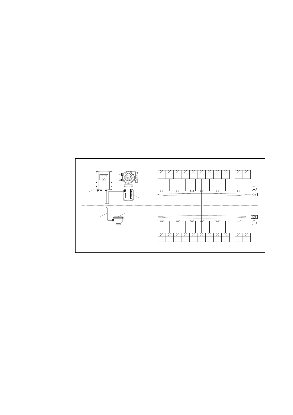
1. Remove the cover (d) from the connection compartment or the sensor housing.
2. Feed the connecting cable (e) through the appropriate cable runs.
3. Establish the connections between sensor and transmitter in accordance with the wiring
diagram (å 19 or wiring diagram inside cover).
4. Seal the connection compartment or the transmitter housing again.
Fig. 19: Connecting the remote version
a Wall-mount housing: non-hazardous area and ATEX II3G / Zone 2 see separate Ex documentation
b Wall-mount housing: ATEX II2G / Zone 1 /FM/CSA see separate Ex documentation
c Remote version, flange version
d Cover of the connection compartment or connection housing
e Connecting cable
Terminal No.: 4/5 = gray; 6/7 = green; 8 = yellow; 9/10 = pink; 11/12 = white; 41/42 = brown
4.3.2 Cable specification for connecting cable
The specifications of the cable connecting the transmitter and the sensor of the remote version are
as follows:
28 Endress+Hauser
!
• 6 × 0.38 mm
• Conductor resistance: 50 /km
• Capacitance core/shield: 420 pF/m
• Cable length: max. 20 m (65 ft)
• Permanent operating temperature: max. +105 °C (+221 °F)
Note!
The cable must be installed securely, to prevents movement.
PVC cable with common shield and individually shielded cores
a0003681
Page 29
Proline Promass 80 PROFIBUS PA Wiring
4.4 Connecting the measuring unit
4.4.1 Terminal assignment
Electrical values for:
•Inputs ä 90
•Outputs ä 90
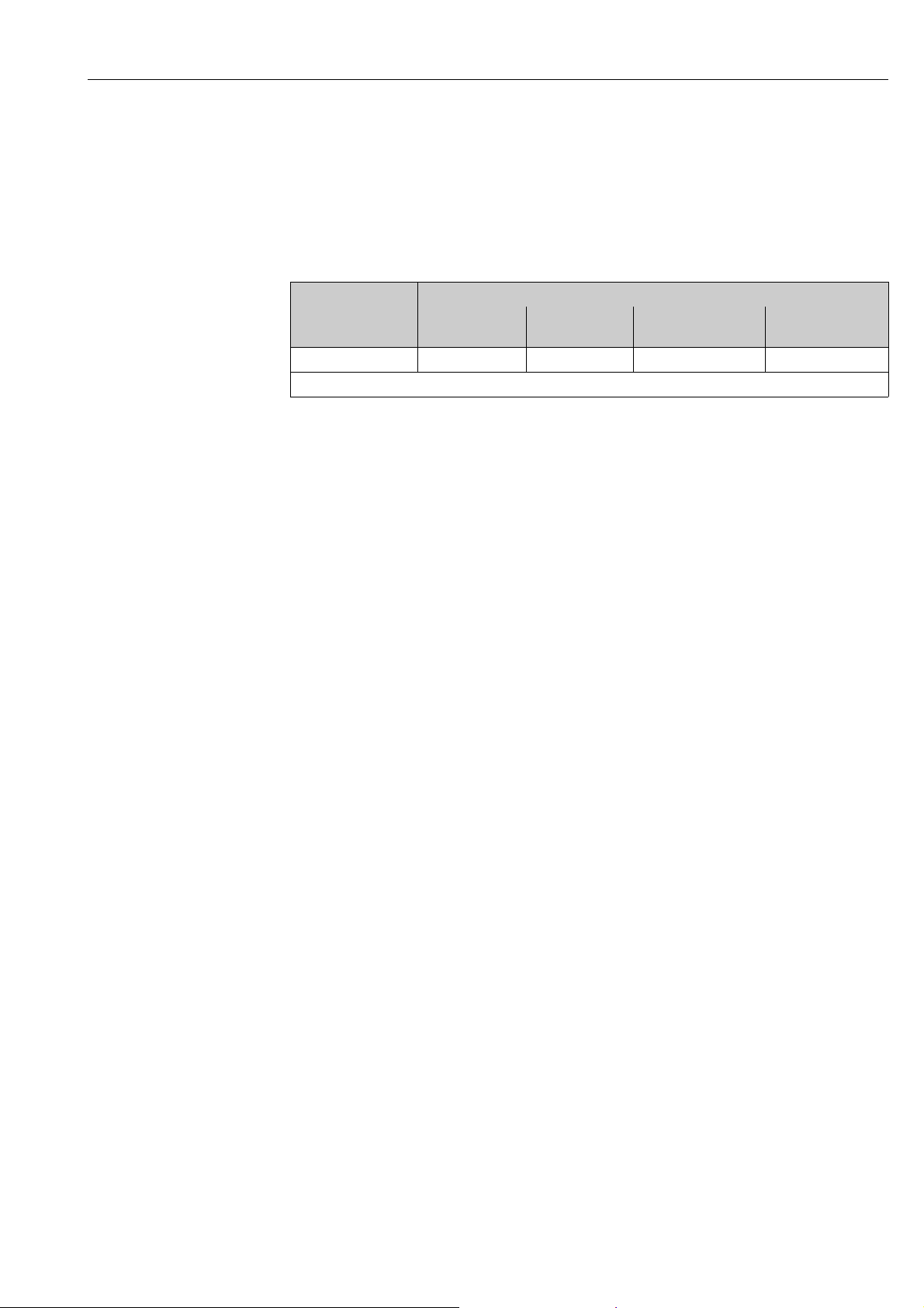
Terminal No. (inputs/outputs)
Order version 20 (+) / 21 (–) 22 (+) / 23 (–) 24 (+) / 25 (–) 26 = PA +
27 = PA –
80***-***********H - - - PROFIBUS PA
With integrated reverse polarity protection
4.4.2 Transmitter connection
1)
1)
#
Warning!
• Risk of electric shock. Switch off the power supply before opening the device. Do not install or
wire the device while it is connected to the power supply. Failure to comply with this precaution
can result in irreparable damage to parts of the electronics.
• Risk of electric shock. Connect the protective earth to the ground terminal on the housing before
the power supply is applied (not required for galvanically isolated power supply).
• Compare the specifications on the nameplate with the local supply voltage and frequency. The
national regulations governing the installation of electrical equipment also apply.
1. Remove the cover (a) from the connection compartment.
2. Route the power supply cable (b) and fieldbus cable (d) through the appropriate cable entries.
Note!
!
The measuring devices can also be supplied with the option of a ready-mounted fieldbus
connector. Further information ä 31.
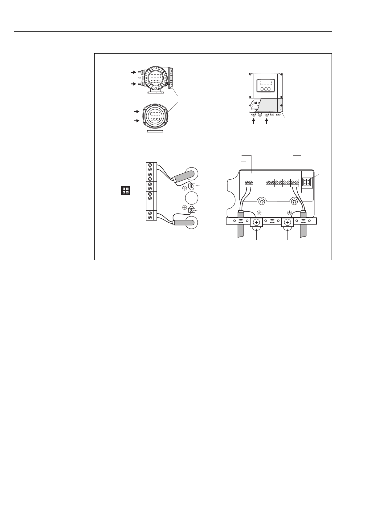
3. Perform wiring: wiring diagram (aluminum housing, stainless steel housing or wall-mount
housing) å 20.
Caution!
"
– Risk of damaging the fieldbus cable!
If the shielding of the cable is grounded at more than one point in systems without additional
potential equalization, power supply frequency equalization currents can occur that damage
the cable or the shielding.
In such cases the shielding of the cable is to be grounded on only one side, i.e. it must not
be connected to the ground terminal of the housing. The shield that is not connected should
be insulated!
– We recommend that the fieldbus cable not be looped using conventional cable glands. If you
later replace even just one measuring device, the bus communication will have to be
interrupted.
Note!
!
– The terminals for the PROFIBUS PA connection (26/27) have integrated reverse polarity
protection. This ensures correct signal transmission via the fieldbus even if lines are mixed
up.
– Conductor cross-section: max. 2.5 mm
– Observe the grounding concept of the plant.
– Connection values ä 29
2
4. Seal the connection compartment again.
Endress+Hauser 29
Page 30
Wiring Proline Promass 80 PROFIBUS PA
d
c
e
b
27
25
23
21
2
1
26
24
22
20
L1 (L+)
PA +
N(L-)
PA –
f
PA –
PA +
1
2
ce
f
b
d
222320 21 24
25
26
27
L1 (L+)
N(L–)
C
a
d
b
a
A
B
d
b
d
b
a0002593
Fig. 20: Connecting the transmitter, cable cross-section: max. 2.5 mm² (AWG 14)
A View A (field housing)
B View B (stainless steel field housing)
C View C (wall-mount housing)
a Connection compartment cover
b Cable for power supply: 85 to 260 V AC, 20 to 55 V AC, 16 to 62 V DC
Terminal No. 1: L1 for AC, L+ for DC
Terminal No. 2: N for AC, L for DC
c Ground terminal for protective earth
d Fieldbus cable:
Terminal No. 26: PA + (with reverse polarity protection)
Terminal No. 27: PA – (with reverse polarity protection)
e Ground terminal for fieldbus cable shield
Observe the following:
– the shielding and grounding of the fieldbus cable ä 27
– that the stripped and twisted lengths of cable shield to the ground terminal are as short as possible
f Service adapter for connecting service interface FXA193 (Fieldcheck, FieldCare)
30 Endress+Hauser
Page 31
Proline Promass 80 PROFIBUS PA Wiring
PG 13.5
M12x1
150/300
(5.91/11.81)
45.0(1.77)
mm (inch)
CD E
3
4
2
1
G
5
6
4
1
2
F
3
7
B
C
D
E
A
Esc
E
-
+
4.4.3 Fieldbus connector
!
Note!
The connector can only be used for PROFIBUS PA devices.
The connection technology of PROFIBUS PA allows measuring devices to be connected to the
fieldbus via uniform mechanical connections such as T-boxes, distribution modules etc.
This connection technology using prefabricated distribution modules and plug-in connectors offers
substantial advantages over conventional wiring:
• Field devices can be removed, replaced or added at any time during normal operation.
Communication is not interrupted.
• Installation and maintenance are significantly easier.
• Existing cable infrastructures can be used and expanded instantly, e.g. when constructing new
star distributors using 4-channel or 8-channel distribution modules.
The device can therefore be supplied with the option of a ready-mounted fieldbus connector.
Fieldbus connectors for retrofitting can be ordered from Endress+Hauser as a spare part ä 66.
Endress+Hauser 31
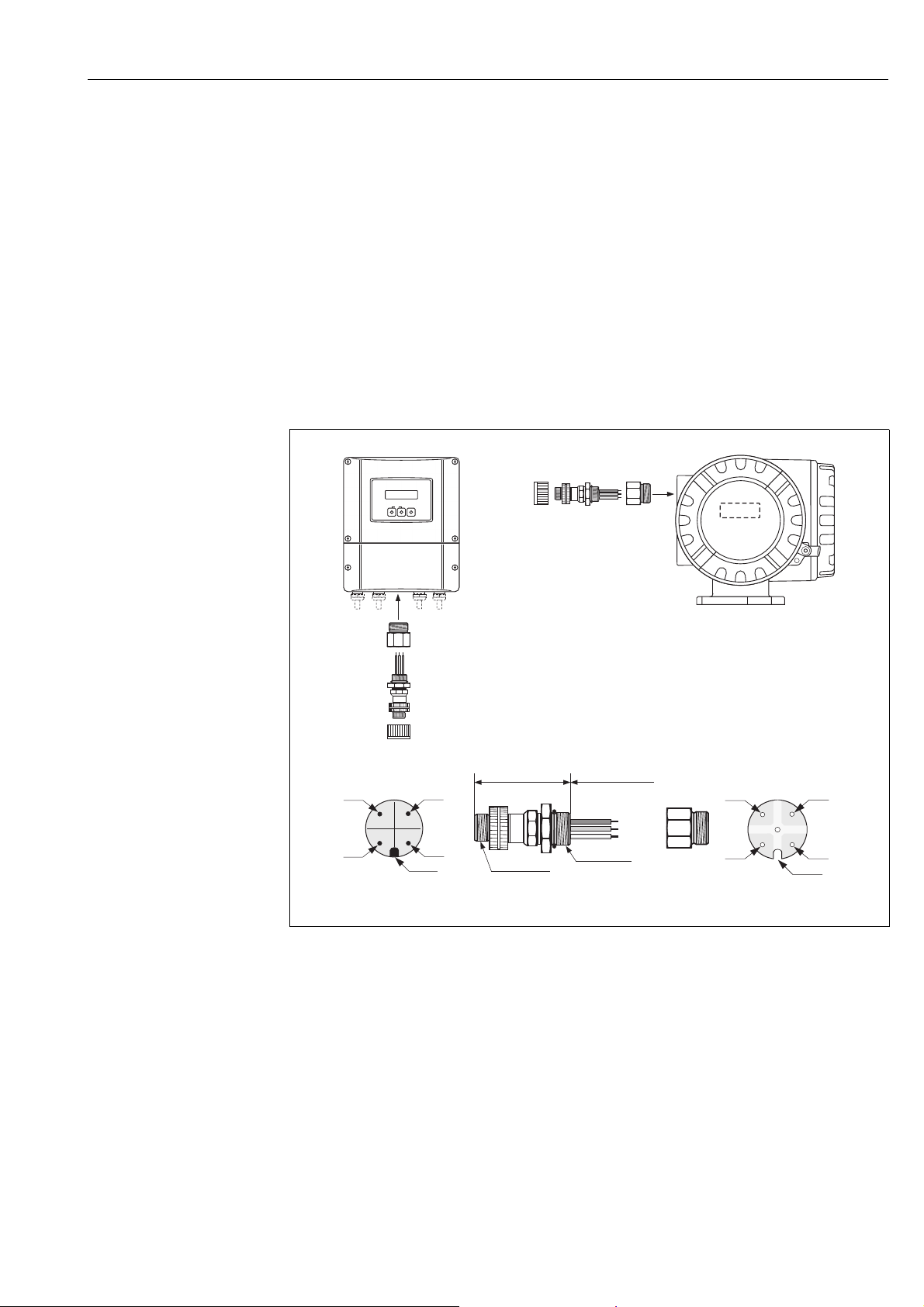
Fig. 21: Connectors for connecting to the PROFIBUS PA
A Aluminum field housing
B Stainless steel field housing
C Protection cap for connector
D Fieldbus connector
E Adapter PG 13.5 / M 20.5
F Connector at housing (male)
G Female connector
Pin assignment / color codes:
1 Brown wire: PA + (terminal 26)
2 Not connected
3 Blue wire: PA – (terminal 27)
4 Black wire: ground (instructions for connection ä 30)
5 Middle female connector not assigned
6 Positioning groove
7 Positioning key
a0005999
Page 32
Wiring Proline Promass 80 PROFIBUS PA
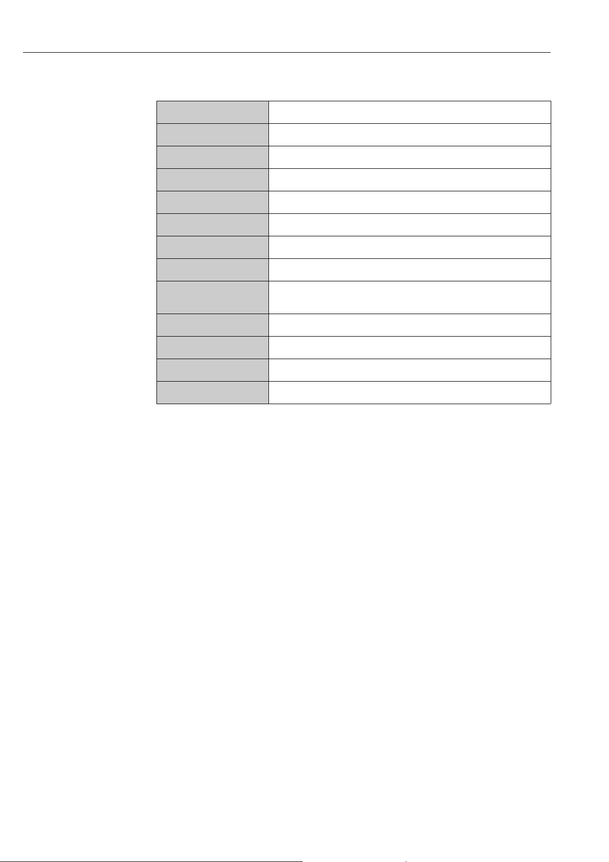
Technical data (fieldbus connector):
Connection cross section 0.75 mm
Connector thread PG 13.5
Degree of protection IP 67 in accordance with DIN 40 050 IEC 529
Contact surface CuZnAu
Housing material Cu Zn, surface Ni
Flammability V - 2 in accordance with UL - 94
Operating temperature –40 to +85 °C (–40 to +185 °F)
Ambient temperature –40 to +150 °C, (–40 to +302 °F)
Nominal current per
contact
Nominal voltage 125 to 150 V DC in accordance with the VDE Standard 01 10/ISO Group 10
Resistance to tracking KC 600
Volume resistance 8 m in accordance with IEC 512 Part 2
Insulation resistance 1012 in accordance with IEC 512 Part 2
2
3 A
Shielding of the cable connection/T-box
Use cable glands with good EMC properties, with surrounding contact of the cable gland (iris
spring). This requires small differences in potential, and possibly potential matching.
• Do not interrupt the shielding of the PA cable.
• Always keep the connection of the shielding as short as possible.
Ideally, cable glands with iris springs should be used for the connection of the shielding. The shield
is placed on the T-box via the iris spring that is inside the cable gland. The shielding mesh is located
under the iris spring. When the PG thread is screwed closed, the iris spring is pressed onto the
shield, making a conductive connection between the shielding and the metal housing.
A junction box or connection is to be considered part of the shielding (Faraday cage). This is
particularly true for offset boxes when these are connected to a PROFIBUS PA measuring device
using a plug-in cable. In such a case, use a metallic plug in which the cable shielding is attached to
the plug housing (such as prefabricated cables).
32 Endress+Hauser
Page 33
Proline Promass 80 PROFIBUS PA Wiring
ab
4.5 Degree of protection
The devices fulfill all the requirements for IP 67.
Compliance with the following points is mandatory following installation in the field or servicing,
in order to ensure that IP 67 protection is maintained:
• The housing seals must be clean and undamaged when inserted into the sealing groove. The seals
must be dried, cleaned or replaced if necessary.
• All the housing screws and screw covers must be firmly tightened.
• The cables used for connection must be of the specified outer diameter ä 91, cable entries.
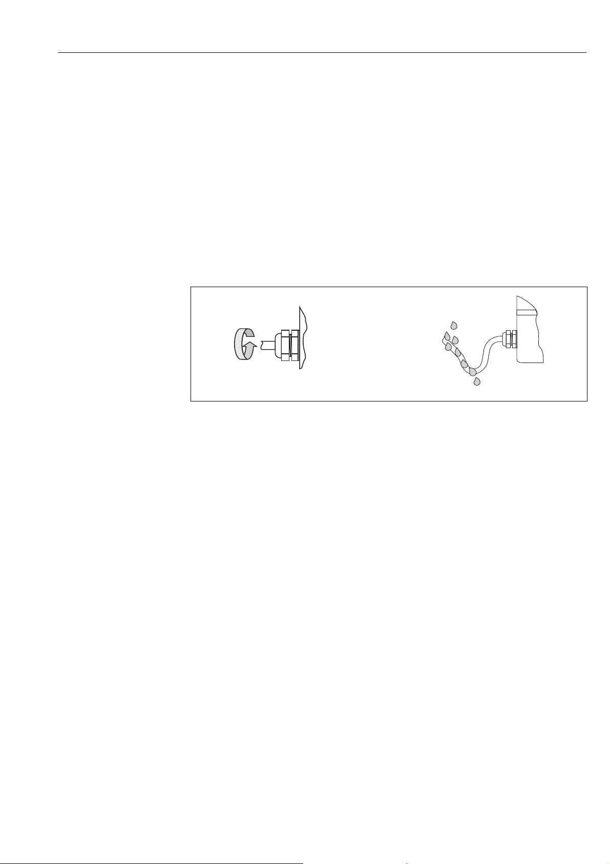
• Firmly tighten the cable entry (point a å 22).
• The cable must loop down in front of the cable entry ("water trap") (point b å 22). This
arrangement prevents moisture penetrating the entry. Always install the measuring device in such
a way that the cable entries do not point upwards.
Note!
!
The cable entries may not be point up.
Fig. 22: Installation instructions, cable entries
• Do not remove the grommet from the cable entry.
• Remove all unused cable entries and insert plugs instead.
Caution!
"
Do not loosen the screws of the sensor housing, as otherwise the degree of protection guaranteed
by Endress+Hauser no longer applies.
a0001914
Endress+Hauser 33
Page 34
Wiring Proline Promass 80 PROFIBUS PA
4.6 Post-connection check
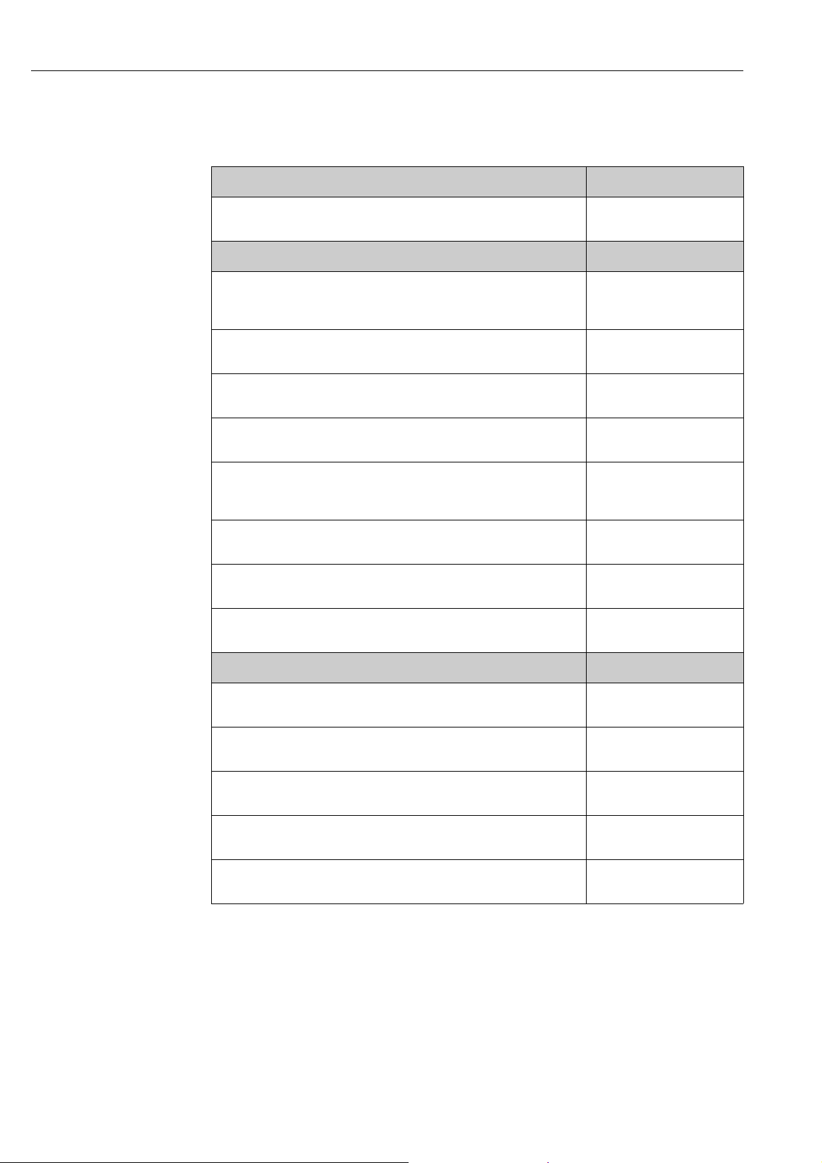
Perform the following checks after completing electrical installation of the measuring device:
Device condition and specifications Notes
Are cables or the device damaged (visual inspection)? -
Electrical connection Notes
Does the supply voltage match the specifications on the nameplate? 85 to 260 V AC (45 to 65 Hz)
20 to 55 V AC (45 to 65 Hz)
16 to 62 V DC
Do the cables comply with the specifications? PROFIBUS PA ä 25
Sensor cable ä 28
Do the cables have adequate strain relief? -
Cables correctly segregated by type?
Without loops and crossovers?
Are the power supply and signal cables correctly connected? See the wiring diagram inside
Are all screw terminals firmly tightened? -
Are all cable entries installed, firmly tightened and correctly sealed?
Cables looped as "water traps"?
Are all housing covers installed and firmly tightened? -
Electrical connection of PROFIBUS Notes
Are all the connecting components (T-boxes, junction boxes, connectors, etc.)
connected with each other correctly?
Has each fieldbus segment been terminated at both ends with a bus terminator? -
Has the max. length of the fieldbus cable been observed in accordance with the
PROFIBUS specifications?
Has the max. length of the spurs been observed in accordance with the PROFIBUS
specifications?
-
the cover of the terminal
compartment
ä 33
-
ä 26
ä 26
Is the fieldbus cable fully shielded and correctly grounded?ä 32
34 Endress+Hauser
Page 35
Proline Promass 80 PROFIBUS PA Operation
2A
3
1
Esc
E
-
+
Esc
E
+
-
XXX.XXX.XX
Esc
E
-
+
FXA193
2B
5Operation
5.1 Quick operation guide
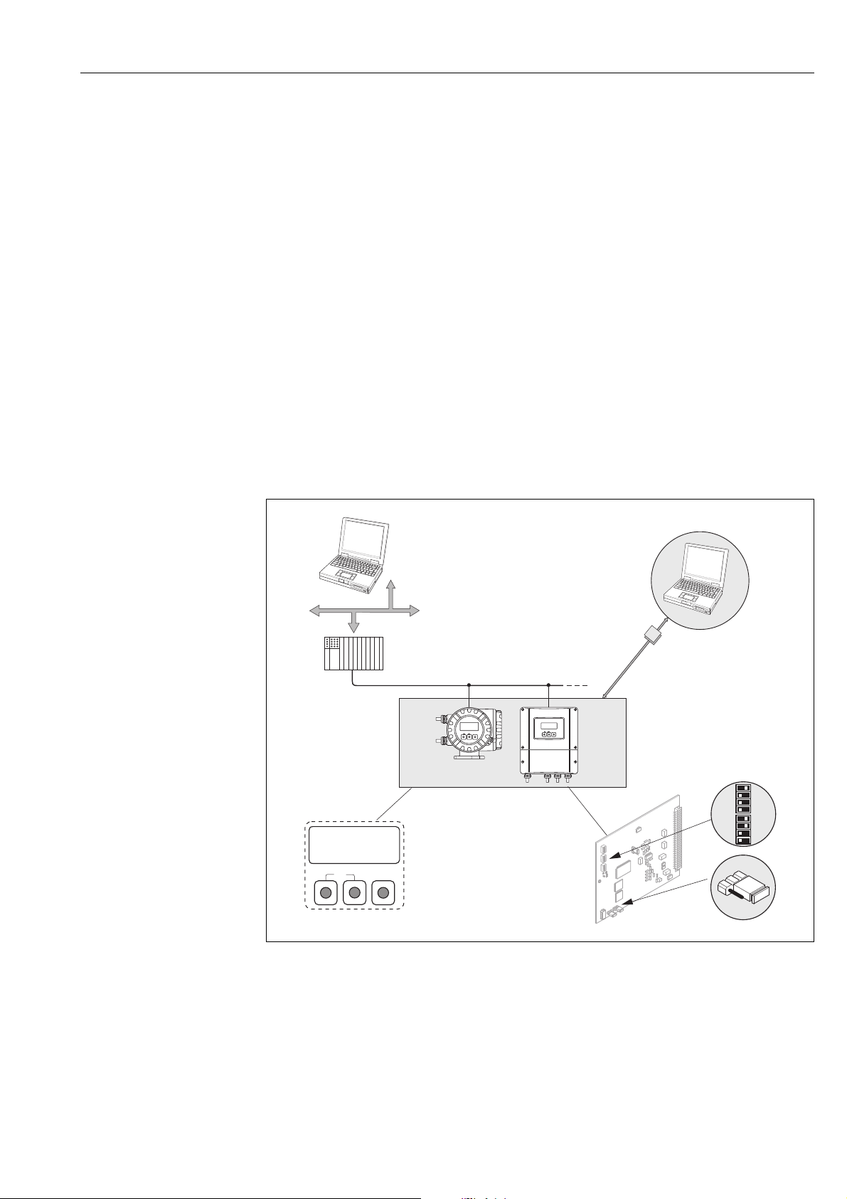
The user has a number of options for configuring and commissioning the device:
1. Local display (option) ä 36
The local display enables you to read all important variables directly at the measuring point,
configure device-specific parameters in the field and perform commissioning.
2. Operating programs ä 41
The configuration of profile and device-specific parameters is primarily done via the PROFIBUS
interface. You can obtain special configuration and operating programs from various
manufacturers for these purposes.
3. Jumpers/miniature switches for hardware settings
– Configuring the device address ä 44
– Hardware write protection ä 43
You can make the following hardware settings using a jumper or miniature switches on the
I/O board:
• Device bus address configuration (for hardware addressing)
• Hardware write protection enabling/disabling
a0001318
Fig. 23: Methods of operating PROFIBUS PA
1 Local display for device operation in the field (option)
2A Configuration/operating programs (e.g. FieldCare) for operation via PROFIBUS PA
2B Configuration/operating program for operating by means of the FXA193 service interface (e.g. FieldCare)
3 Jumper/miniature switches for hardware settings (write protection, device address)
Endress+Hauser 35
Page 36
Operation Proline Promass 80 PROFIBUS PA
Esc
E
+
-
1
32
+48.25 xx/yy
+3702.6 x
5.2 Local display
5.2.1 Display and operating elements
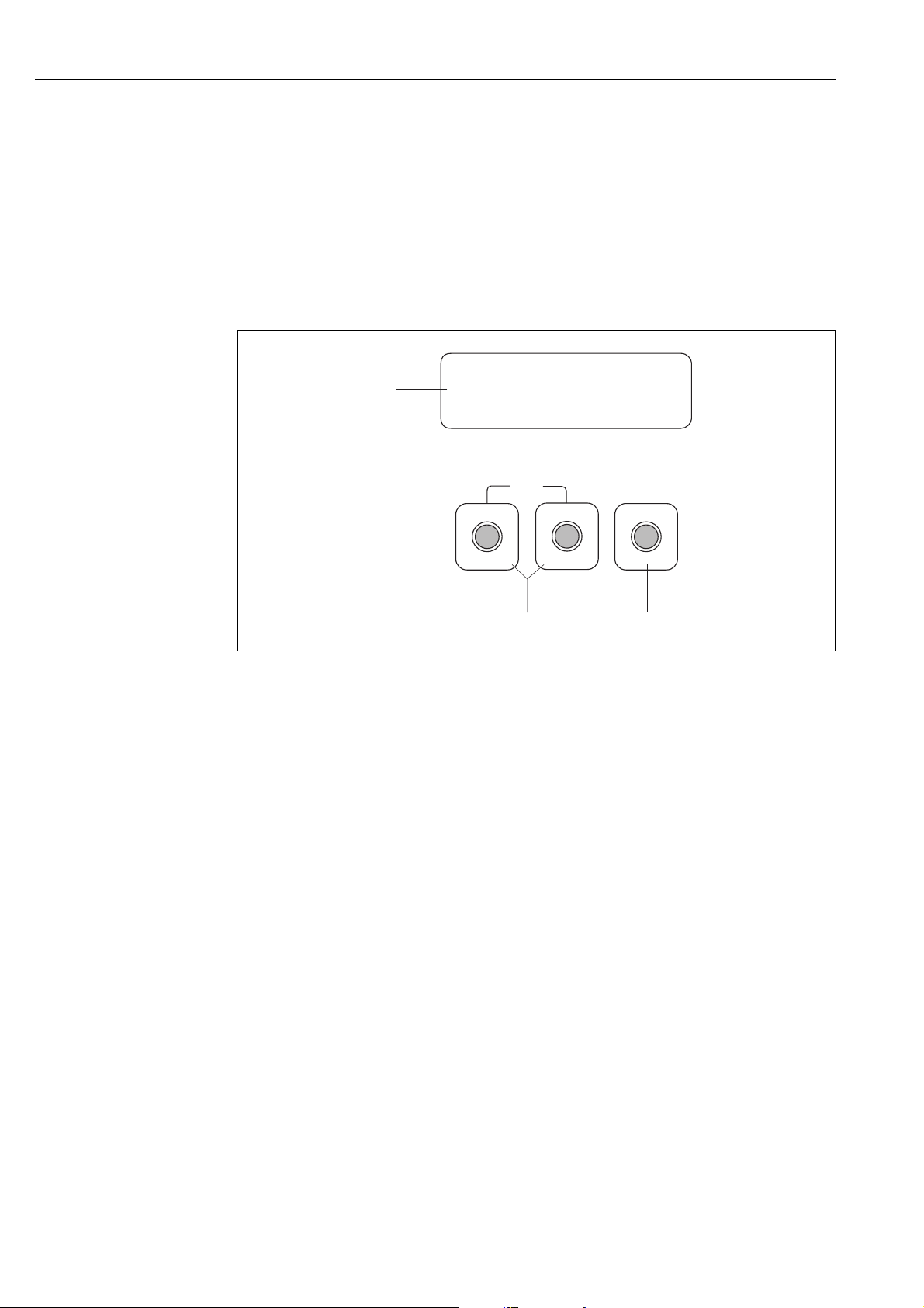
The local display enables you to read all important parameters directly at the measuring point and
configure the device using the "Quick Setup" or the function matrix.
The display consists of four lines; this is where measured values and/or status variables (direction
of flow, empty pipe, bar graph, etc.) are displayed. You can change the assignment of display lines
to different variables to suit your needs and preferences ( "Description of Device Functions"
manual).
A0001141
Fig. 24: Display and operating elements
1 Liquid crystal display
The two-line liquid crystal display shows measured values, dialog texts, fault messages and notice messages. The
display as it appears when normal measuring is in progress is known as the HOME position (operating mode).
– Top line: shows main measured values, e.g. volume flow, [e.g. in ml/min]
– Bottom line: shows the totalizer reading [e.g. in m
– Bargraph display, tag name
2
3
keys
O/ S
–HOME position Direct access to totalizer values and actual values of inputs/outputs
– Enter numerical values, select parameters
– Select different function groups within the function matrix
Press the +/- keys (
– Exit the function matrix step by step HOME position
– Press and hold down +/– keys for longer than 3 seconds
– Cancel data entry
key (Enter key)
F
–HOME position Entry into the function matrix
– Save the numerical values you input or settings you changed
) simultaneously to trigger the following functions:
X
3
]
Return directly to HOME position
36 Endress+Hauser
Page 37
Proline Promass 80 PROFIBUS PA Operation
5.2.2 Icons
The icons which appear in the field on the left make it easier to read and recognize measured
variables, device status, and error messages.
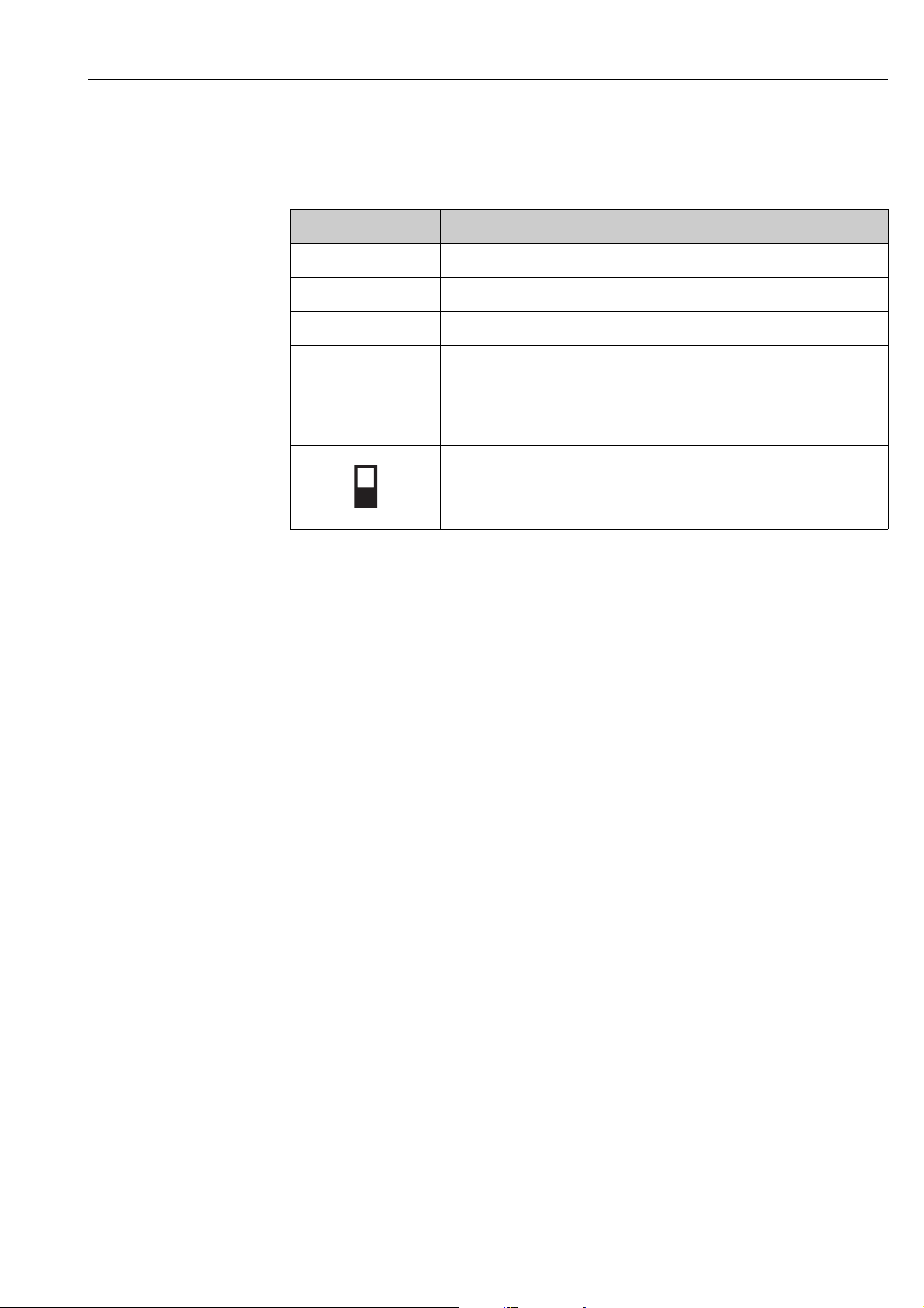
Icons Meaning
S System error
! Notice message
P Process error
$
(scrolling display)
Fault message
Cyclic communication via PROFIBUS active, for example via PLC (Class 1 master)
Acyclic communication via PROFIBUS active,
e.g. via FieldCare
a0001206
Endress+Hauser 37
Page 38
Operation Proline Promass 80 PROFIBUS PA
>3s
-
+
E
Esc
E
E
E
E
E E E E E
–
+
+
Esc
–
+
Esc
–
+
Esc
–
E
m
n
o
p
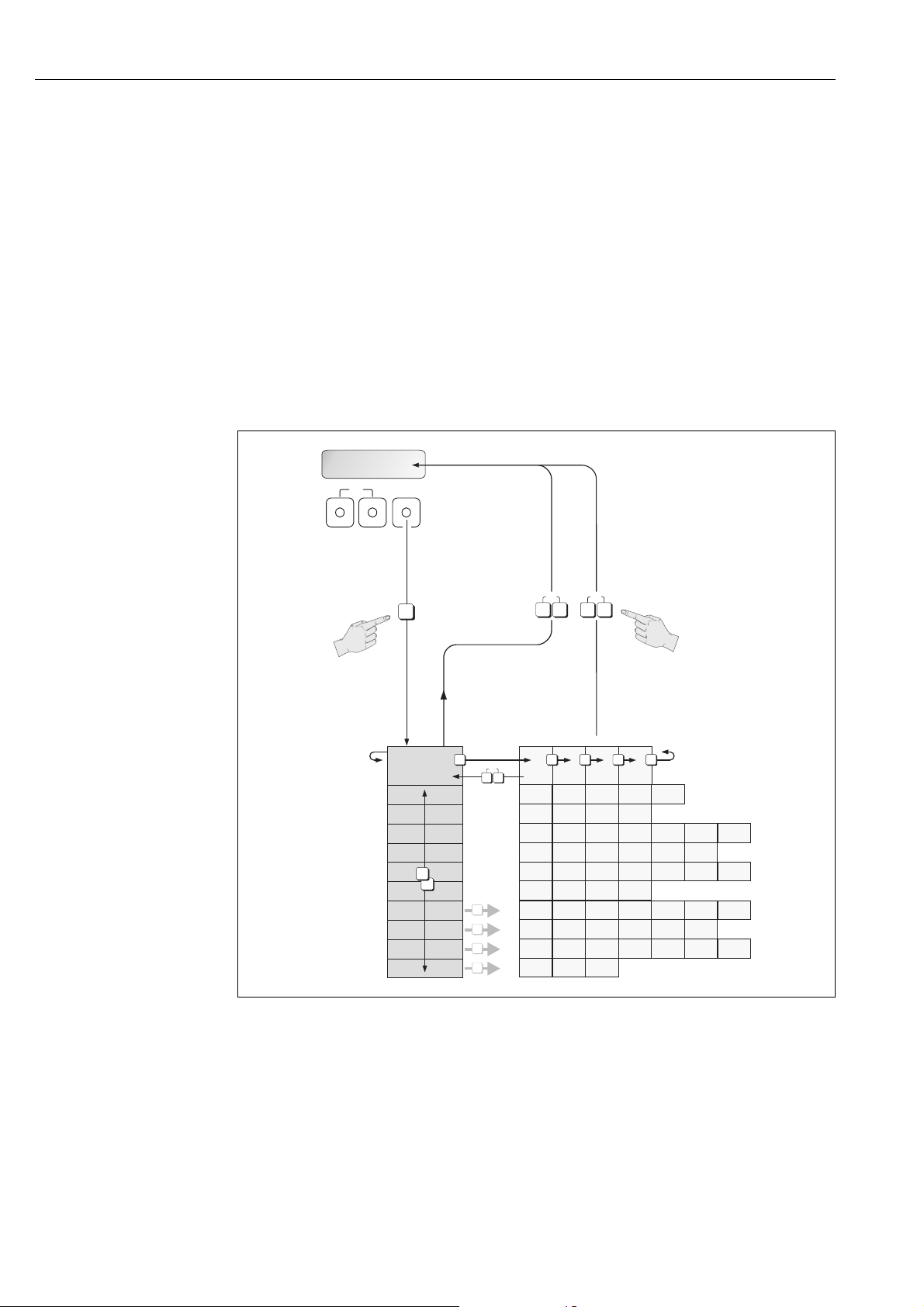
5.3 Brief operating instructions on the function matrix
!
Note!
• See the general notes ä 39
• Function descriptions see the "Description of Device Functions" manual"
1. HOME position F Entry into the function matrix
2. Select a function group (e.g. CURRENT OUTPUT 1)
3. Select a function (e.g. TIME CONSTANT)
Change parameter / enter numerical values:
Select or enter release code, parameters, numerical values
P
Save your entries
F
4. Exit the function matrix:
– Press and hold down Esc key (X) for longer than 3 seconds HOME position
– Repeatedly press Esc key (X) Return step-by-step to HOME position
Fig. 25: Selecting functions and configuring parameters (function matrix)
38 Endress+Hauser
a0001142
Page 39

Proline Promass 80 PROFIBUS PA Operation
5.3.1 General notes
The Quick Setup menu contains the default settings that are adequate for commissioning.
Complex measuring operations on the other hand necessitate additional functions that you can
configure as necessary and customize to suit your process parameters. The function matrix,
therefore, comprises a multiplicity of additional functions which, for the sake of clarity, are arranged
in a number of function groups.
Comply with the following instructions when configuring functions:
• You select functions as described earlier ä 38.
• You can switch off certain functions (OFF). If you do so, related functions in other function groups
will no longer be displayed.
• Certain functions prompt you to confirm your data entries.
Press P to select "SURE [ YES ]" and press F to confirm. This saves your setting or starts a
function, as applicable.
• Return to the HOME position is automatic if no key is pressed for 5 minutes.
• Programming mode is disabled automatically if you do not press a key within 60 seconds
following automatic return to the HOME position.
Caution!
"
All functions are described in detail, as is the function matrix itself, in the "Description of Device
Functions" manual which is a separate part of these Operating Instructions.
!
Note!
• The transmitter continues to measure while data entry is in progress, i.e. the current measured
values are output via the signal outputs in the normal way.
• If the power supply fails all preset and configured values remain safely stored in the EEPROM.
5.3.2 Enabling the programming mode
The function matrix can be disabled. Disabling the function matrix rules out the possibility of
inadvertent changes to device functions, numerical values or factory settings. A numerical code
(factory setting = 80) has to be entered before settings can be changed.
If you use a code number of your choice, you exclude the possibility of unauthorized persons
accessing data see the "Description of Device Functions" manual.
Comply with the following instructions when entering codes:
• If programming is disabled and the P operating elements are pressed in any function, a prompt
for the code automatically appears on the display.
• If "0" is entered as the customer's code, programming is always enabled!
• The Endress+Hauser service organization can be of assistance if you mislay your personal code.
Caution!
"
Changing certain parameters such as all sensor characteristics, for example, influences numerous
functions of the entire measuring system, particularly measuring accuracy.
There is no need to change these parameters under normal circumstances and consequently, they
are protected by a special code known only to the Endress+Hauser service organization. Please
contact Endress+Hauser if you have any questions.
5.3.3 Disabling the programming mode
Programming mode is disabled if you do not press an operating element within 60 seconds following
automatic return to the HOME position.
You can also disable programming in the "ACCESS CODE" function by entering any number (other
than the customer's code).
Endress+Hauser 39
Page 40
Operation Proline Promass 80 PROFIBUS PA
1
2453
XXXXXXXXXX
#000 00:00:05
P
5.4 Error messages
5.4.1 Type of error
Errors that occur during commissioning or measuring are displayed immediately. If two or more
system or process errors occur, the error with the highest priority is the one shown on the display.
The measuring system distinguishes between two types of error:
• System error:
Includes all device errors, e.g. hardware errors, etc. ä 70
• Process error:
Includes all application errors, e.g. fluid not homogeneous, etc. ä 76
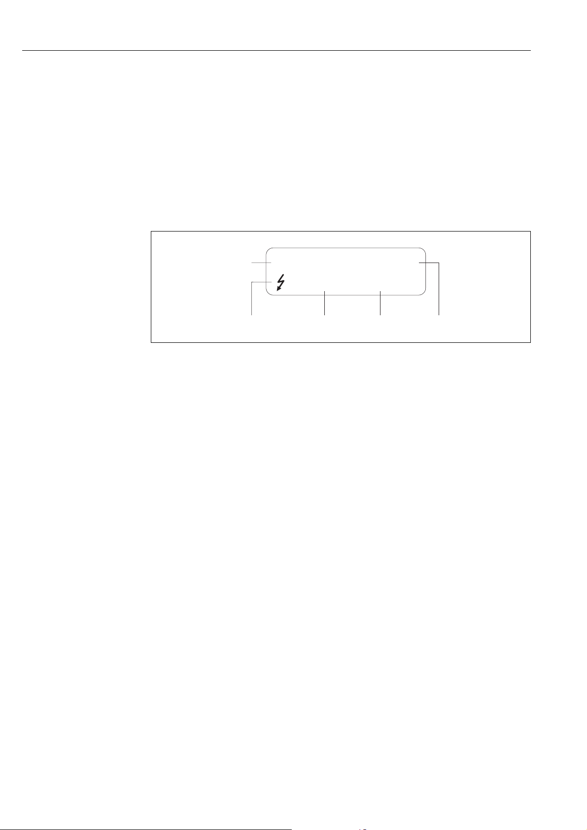
a0000991
Fig. 26: Error messages on the display (example)
1 Error type: P = process error, S = system error
2 Error message type:
3 Error designation: e.g. MEDIUM INHOM. = fluid is not homogeneous
4 Error number: e.g. #702
5 Duration of last error to occur (in hours, minutes and seconds)
= fault message, ! = notice message, definition
$
5.4.2 Error message type
The measuring device always assigns system and process errors which occur to two types of error
messages (fault or notice messages), resulting in different weightings ä 68.
Serious system errors, e.g. module defects, are always identified and classed as "fault messages" by
the measuring device.
Notice message (!)
• The error in question has no effect on the current operation
• Displayed as Exclamation mark (!), type of error (S: system error, P: process error)
• PROFIBUS device status display, error display ä 70
Fault message ( $)
• The error in question interrupts or stops the current operation
• Displayed as Lightning flash ( $ ), type of error (S: system error, P: process error)
• PROFIBUS device status display, error display ä 70
40 Endress+Hauser
Page 41

Proline Promass 80 PROFIBUS PA Operation
5.5 Operating options
For the complete operation of the measuring device, including device-specific commands, device
description (DD) files are available to the user to provide the following operating aids and programs:
5.5.1 FieldCare
FieldCare is Endress+Hauser’s FDT-based plant asset management tool and allows the configuration
and diagnosis of intelligent field devices. By using status information, you also have a simple but
effective tool for monitoring devices. The Proline flowmeters are accessed via a service interface or
via the service interface FXA193.
5.5.2 Operating program "SIMATIC PDM" (Siemens)
SIMATIC PDM is a standardized, manufacturer-independent tool for the operation, configuration,
maintenance and diagnosis of intelligent field devices.
Endress+Hauser 41
Page 42
Operation Proline Promass 80 PROFIBUS PA
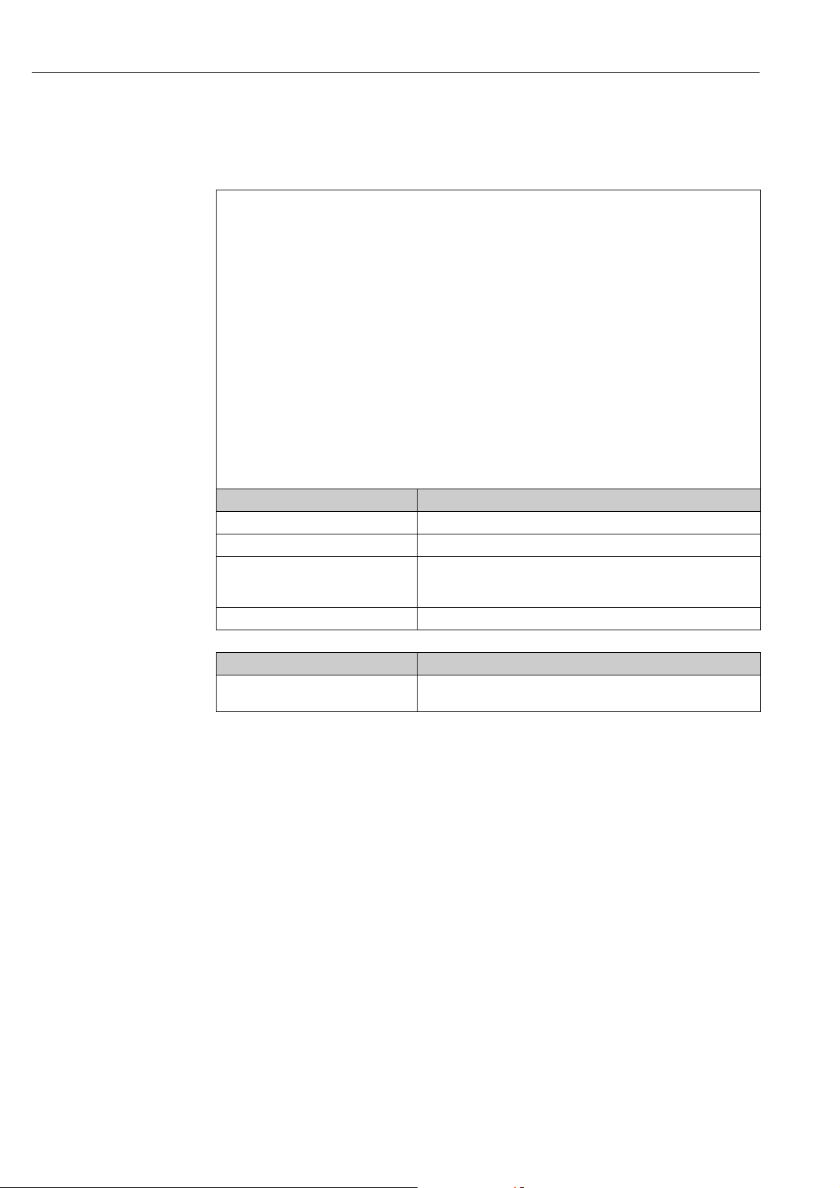
5.5.3 Device description files for operating programs
The following table illustrates the suitable device description file for the operating program in
question and then indicates where these can be obtained.
Valid for device software: 3.06.XX DEVICE SOFTWARE function
Device data PROFIBUS PA:
Profile Version:
Promass 80 ID No.:
Profile ID No.:
GSD file information:
Promass 80 GSD file: Extended Format
Bitmaps: EH_1528_d.bmp/.dib
Profile GSD file: PA139742.gsd
Software release: 06.2010
Operating program/device description: Sources for obtaining device descriptions/program updates:
Promass 80 GSD file • www.endress.com Download
Profile GSD file • www.profibus.com
FieldCare/DTM • www.endress.com Download
SIMATIC PDM • www.endress.com Download
3.0
1528hex
9742 (Hex)
(recommended):
Standard Format:
Note!
!
Before configuring the PROFIBUS network, read and follow the information
for using the GSD file ä 49
EH_1528_n.bmp/.dib
EH_1528_s.bmp/.dib
• CD–ROM (Endress+Hauser order number: 56004088)
• DVD (Endress+Hauser order number: 70100690)
PROFILE VERSION function
DEVICE ID function
eh3x1528.gsd
eh3_1528.gsd
!
Tester/simulator: How to acquire:
Fieldcheck • Update by means of FieldCare with the Flow Device FXA193/291 DTM
in the Fieldflash Module
Note!
The Fieldcheck tester/simulator is used for testing flowmeters in the field. When used in
conjunction with the "FieldCare" software package, test results can be imported into a database,
printed and used for official certification. Contact your Endress+Hauser representative for more
information.
42 Endress+Hauser
Page 43
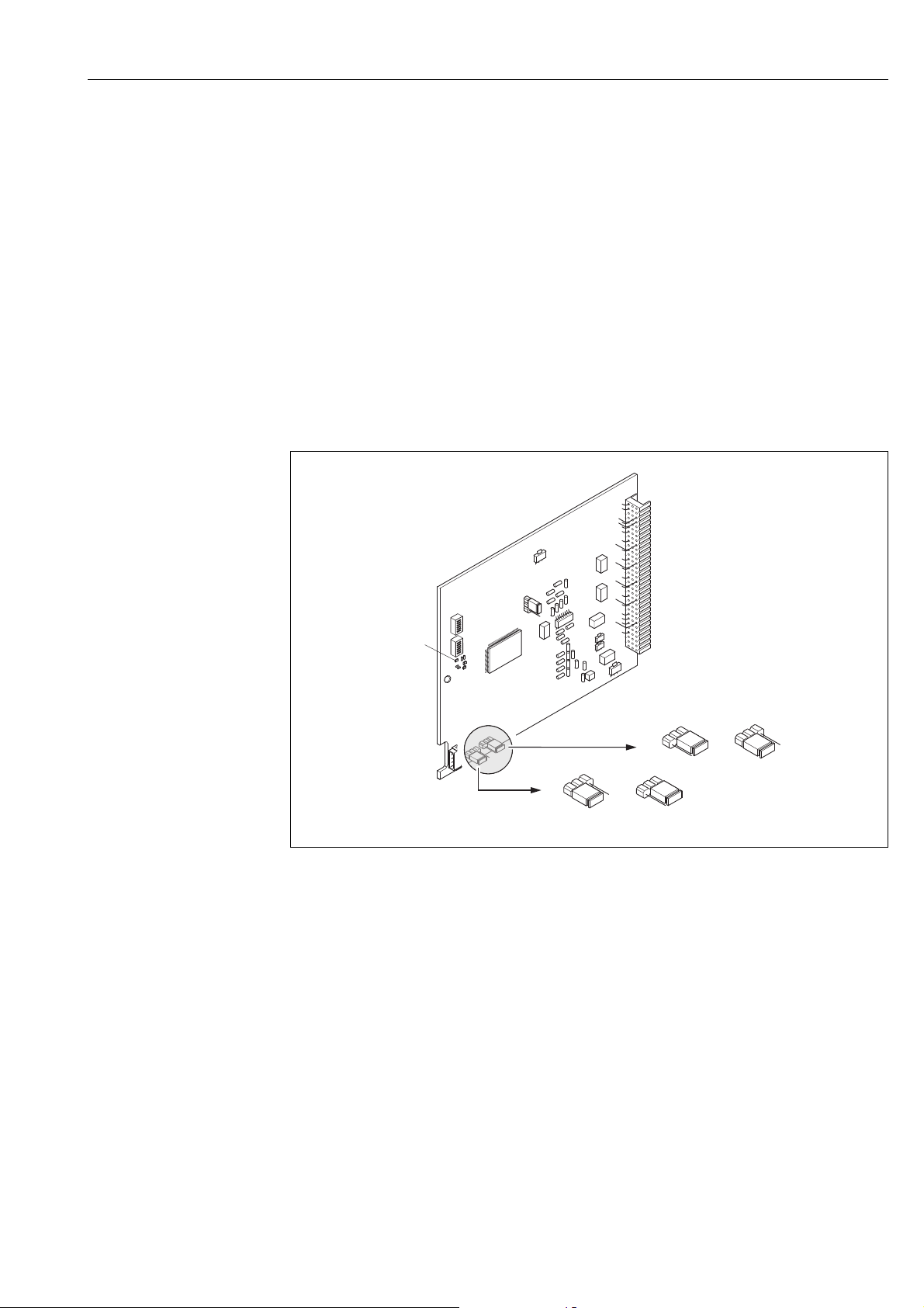
Proline Promass 80 PROFIBUS PA Operation
1
1.21.1
2
LED
5.6 PROFIBUS PA hardware settings
5.6.1 Hardware write protection
A jumper on the I/O board provides the means of switching hardware write protection on or off.
When hardware write protection is switched on, it is not possible to write to the device functions
via PROFIBUS (acyclic data transmission, e.g. via the operating program "FieldCare").
#
Warning!
Risk of electric shock. Exposed components carry dangerous voltages. Make sure that the power
supply is switched off before you remove the cover of the electronics compartment.
1. Switch off power supply.
2. Remove the I/O board ä 80.
3. Configure the hardware write protection accordingly with the aid of the jumpers å 27.
4. Installation is the reverse of the removal procedure.
a0001359
Fig. 27: Switching write protection on and off with the aid of a jumper on the I/O board
1 Jumper for switching write protection on and off
1.1 Write protection switched off (factory setting) = it is possible to write to the device functions via PROFIBUS
(acyclic data transmission, e.g. via the operating program "FieldCare")
1.2 Write protection switched on = it is not possible to write to the device functions via PROFIBUS (acyclic data
transmission, e.g. via the operating program "FieldCare")
2 Jumper without function
LED Overview of LED states:
– Lit continuously Ready for operation
– Not lit Not ready for operation
– Flashing System or process error present ä 68
Endress+Hauser 43
Page 44
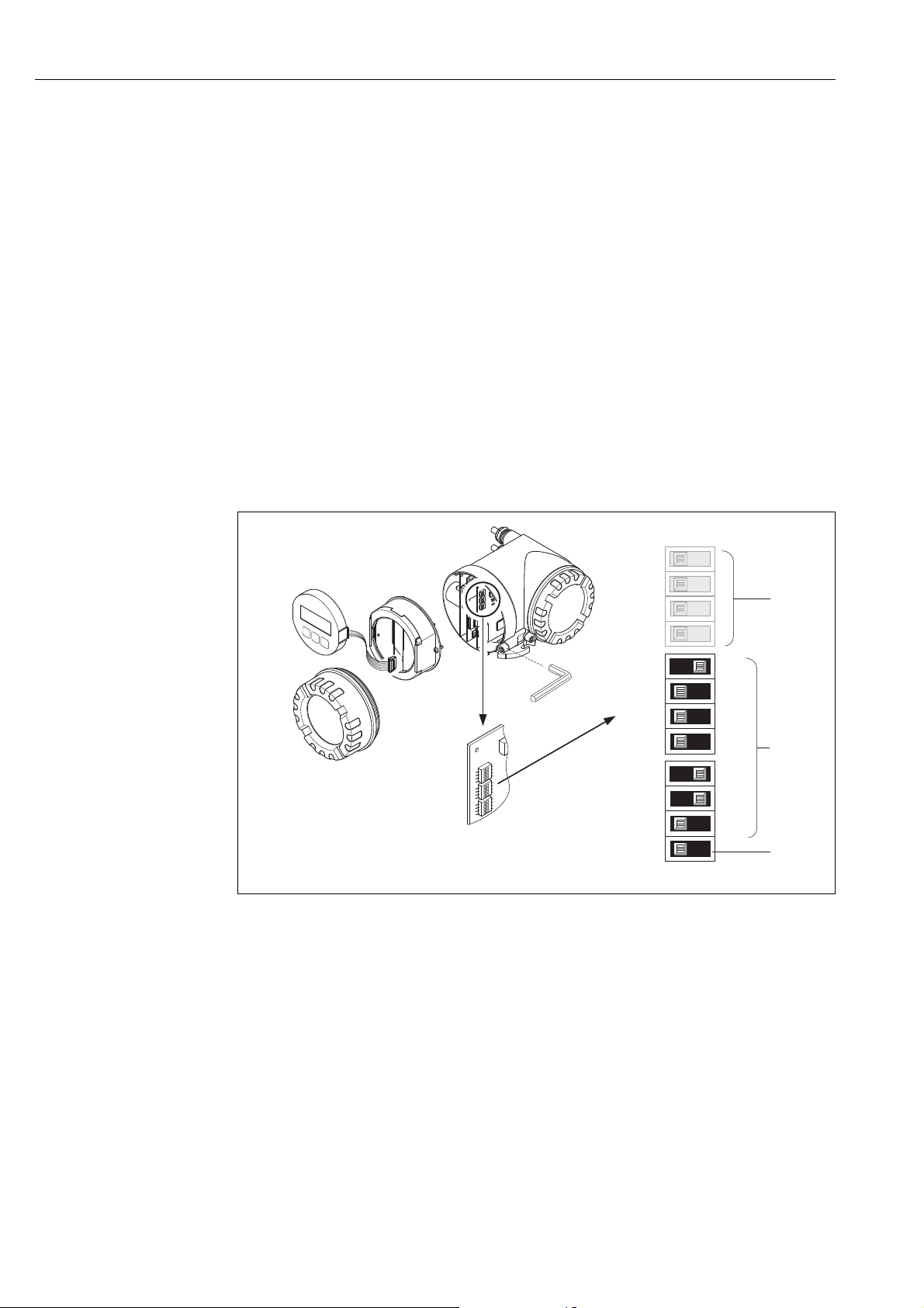
Operation Proline Promass 80 PROFIBUS PA
1
2
3
4
W
E
N
O
1
2
3
4
W
E
N
O
1
2
3
4
W
E
N
O
161
3
322
4
643
4
1
2
b
OFF ON
11
22
43
84
a
OFF ON
c
1
2
3
4
W
E
N
O
1
2
3
4
W
E
N
O
1
2
3
4
W
E
N
O
5.6.2 Configuring the device address
The address must always be configured for a PROFIBUS PA device. The valid device addresses are
in the range from 1 to 126. In a PROFIBUS PA network, each address can only be assigned once. If
an address is not configured correctly, the device is not recognized by the master. All measuring
devices are delivered from the factory with the address 126 and with software addressing.
Addressing via local operation/operating program ä 41
Addressing via miniature switches
#
Warning!
Risk of electric shock. Exposed components carry dangerous voltages. Make sure that the power
supply is switched off before you remove the cover of the electronics compartment.
1. Loosen the Allen screw (3 mm) of the securing clamp.
2. Unscrew cover of the electronics compartment from the transmitter housing.
3. Remove the local display (if present) by loosening the set screws of the display module.
4. Set the position of the miniature switches on the I/O board using a sharp pointed object.
5. Installation is the reverse of the removal procedure.
a0002590
Fig. 28: Addressing with the aid of miniature switches on the I/O board
a Miniature switches for setting the device address (illustrated: 1 + 16 + 32 = device address 49)
b Miniature switches for the address mode (method of addressing):
OFF = software addressing via local operation/operating program (factory setting)
ON = hardware addressing via miniature switches
c Miniature switches not assigned
44 Endress+Hauser
Page 45

Proline Promass 80 PROFIBUS PA Commissioning
6 Commissioning
6.1 Function check
Make sure that the following function checks have been performed successfully before switching on
the supply voltage for the measuring device:
• Checklist for "Post-installation check" ä 24
• Checklist for "Post-connection check" ä 34
6.2 Switching on the measuring device
Once the function check has been performed successfully, the device is operational and can be
switched on via the supply voltage. The device then performs internal test functions and the
following messages are shown on the local display:
!
PROMASS 80
START UP…
▼
DEVICE SOFTWARE
V XX.XX.XX
▼
SYSTEM OK
OPERATION
Normal measuring mode commences as soon as startup completes.
Various measured value and/or status variables appear on the display (HOME position).
Note!
If startup fails, an error message indicating the cause is displayed.
Start-up message
Current software version
Beginning of normal measuring mode
Endress+Hauser 45
Page 46
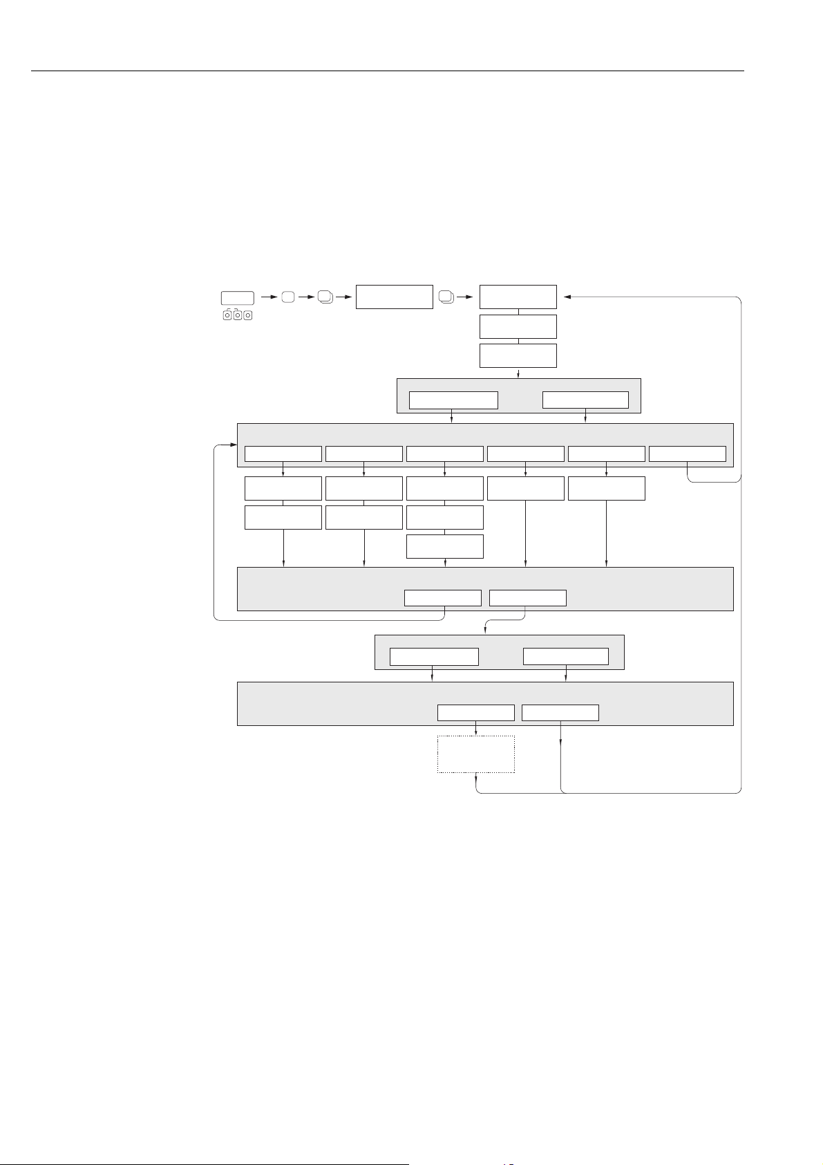
Commissioning Proline Promass 80 PROFIBUS PA
+
+
+
E
E
HOME-POSITION
Esc
E
+
-
XXX.XXX.XX
Yes
Yes
No
No
Mass flow Volume flow Density
Selection System Units
Configuration another unit ?
Automatically configuration display ?
Temperature Quit
Unit
Mass flow
Unit
flowVolume
Unit
Density
Unit
Temperature
Unit
Totalizer
Unit
Totalizer
Automatically
parameterization
of the display
Language
Pre-setting
Quick Setup
Quick Setup
Commission
n
o
Corr. Vol. flow
Unit
Corr. Vol. flow
Unit
Ref. Density
Fix
Ref. Density
p
Selection pre-settings
Actual SettingsDeliver Settingsy
m
Set Unit to Bus
SET UNITSOFF
m
6.3 Quick Setup
In the case of measuring devices without a local display, the individual parameters and functions
must be configured via the operating program, e.g. FieldCare.
If the measuring device is equipped with a local display, all the important device parameters for
standard operation, as well as additional functions, can be configured quickly and easily by means
of the following Quick Setup menus.
6.3.1 Quick Setup "Commissioning"
Fig. 29: Quick Setup "Commissioning"
!
• The display returns to the cell SETUP COMMISSIONING (1002) if you the press X key combination during
parameter interrogation. The stored parameters remain valid.
• The "Commissioning" Quick Setup must be carried out before one of the Quick Setups explained below is run.
The "DELIVERY SETTINGS" option sets every selected unit to the factory setting.
m
The "ACTUAL SETTINGS" accepts the units you configured beforehand.
Only units not yet configured in the current Setup are offered for selection in each cycle. The unit for mass, volume
n
and corrected volume is derived from the corresponding flow unit.
The "YES" option remains visible until all the units have been configured. "NO" is the only option displayed when
o
no further units are available.
The “automatic parameterization of the display” option contains the following basic settings/factory settings:
p
YES: line 1= mass flow; line 2 = totalizer 1
NO: The existing (selected) settings remain.
Note!
a0004749-en
46 Endress+Hauser
Page 47

Proline Promass 80 PROFIBUS PA Commissioning
6.4 Commissioning the PROFIBUS PA interface
!
Note!
• All functions required for commissioning are described in detail in the "Description of Device
Functions" manual which is a separate part of these Operating Instructions.
• A code (factory setting: 80) must be entered to change device functions, numerical values or
factory settings.
The following steps must be carried out in the sequence specified:
1. Check the hardware write protection:
The WRITE PROTECT parameter indicates whether it is possible to write to the device via
PROFIBUS communication (e.g. via FieldCare).
Note!
!
This check is not needed if operating via the local display.
COMMUNICATION WRITE PROTECT…
… OFF displayed (factory setting): write access via PROFIBUS possible
… ON displayed: write access via PROFIBUS not possible
Deactivate the write protection if necessary ä 43
2. Enter the tag name (optional):
COMMUNICATION TAG NAME
3. Configuring the fieldbus address:
Set the bus address:
– Software addressing using the local display:
COMMUNICATION BUS ADDRESS
– Hardware addressing via miniature switches ä 44
4. Select the system units:
• Via the system units group:
SYSTEM UNITS UNIT VOL. FLOW UNIT VOLUME UNIT…
• In the SET UNIT TO BUS function, select the SET UNITS function to transfer the cyclically
transmitted volume flow to the PROFIBUS master (Class 1) with the system unit set in the
measuring device.
COMMUNICATION SET UNIT TO BUS
Note!
!
– The configuration of the engineering units for the totalizers is described separately see
Point 6
– If a system unit is altered via local operation, this initially does not affect the unit that is used
to transfer the volume flow to the automation system.
The SET UNIT TO BUS function has to be activated in the COMMUNICATION block before
the altered system unit of the measured value is transmitted to the automation system.
5. Setting the measuring mode:
SYSTEM PARAMETER MEASURING MODE
Select the flow components that should be recorded by the measuring device:
– UNIDIRECTIONAL (factory setting) = only the positive flow portions
– BIDIRECTIONAL = the positive and negative flow components
Endress+Hauser 47
Page 48

Commissioning Proline Promass 80 PROFIBUS PA
6. Configuration of the totalizer:
The measuring device has one totalizer.
• You can assign a measured variable to the totalizer via the CHANNEL parameter:
TOTALIZER CHANNEL …
… VOLUME FLOW option (CHANNEL = 273), factory setting: the volume flow is
totalized as the measured variable
… OFF option (CHANNEL = 0): no totalizing, the value 0 is displayed as the totalizer
value
Note!
!
If the module or the TOTAL function was integrated when configuring the PROFIBUS
network, the measured variable selected in the CHANNEL parameter is cyclically
transmitted to the PROFIBUS master (Class 1) (further information ä 52).
• Enter the desired totalizer units:
TOTALIZER UNIT TOTALIZER (factory setting: m³)
• Configure totalizer status (e.g. totalize):
TOTALIZER SET TOTALIZER…
… Select: TOTALIZE
• Configure the totalizer mode:
TOTALIZER TOTALIZER MODE…
… BALANCE option (factory setting): calculates the positive and negative flow
components
… POSITIVE option: calculates the positive flow components only
… NEGATIVE option: calculates the negative flow components only
… HOLD VALUE option: the totalizer remains at the last value
Note!
!
For the calculation of the positive and negative flow components (BALANCE) or the negative
flow components only (NEGATIVE) to be carried out correctly, the option BIDIRECTIONAL
must be active in the SYSTEM PARAMETER MEASURING MODE function.
7. Select the operating mode:
Select the operating mode (GSD file) which should be used for cyclic data transmission to the
PROFIBUS master.
COMMUNICATION SELECTION GSD…
… MANUFACT. SPEC. option (factory setting): the complete device functionality is
available
… PROFILE-GSD option: the device is operated in the PROFIBUS Profile mode
Note!
!
For PROFIBUS network configuration, make sure that the right device master file (GSD file) of
the measuring device is used for the selected operating mode ä 49.
8. Configuration of cyclic data transmission in the PROFIBUS master
A detailed description of the system integration can be found on ä 49.
48 Endress+Hauser
Page 49
Proline Promass 80 PROFIBUS PA Commissioning
6.5 PROFIBUS PA system integration
6.5.1 Device master file (GSD file)
For PROFIBUS network configuration, the device master file (GSD file) is needed for every bus user
(PROFIBUS slave). The GSD file contains a description of the properties of a PROFIBUS device, such
as supported data transmission rate and number of input and output data.
Before configuration takes place, a decision should be made as to which GSD file should be used to
operate the measuring device in the PROFIBUS DP master system.
The measuring device supports the following GSD files:
• Promass 80 GSD file (manufacturer-specific GSD file, complete device functionality)
• PROFIBUS Profile GSD file.
Below you will find a detailed description of the GSD files supported.
Promass 80 GSD file (manufacturer-specific GSD file, complete device functionality)
Use this GSD file to access the complete functionality of the measuring device. In this way, devicespecific measured variables and functionalities are thus completely available in the PROFIBUS
master system. An overview of the modules available (input and output data) is contained on the
following pages: PROFIBUS PA ä 52
GSD file with standard or extended format
The GSD file with either the standard or the extended format must be used depending on the
configuration software used. When installing the GSD file, the GSD file with the extended format
(EH3x15xx.gsd) should always be used first.
However, if the installation or the configuration of the measuring device fails with this format, then
use the standard GSD (EH3_15xx.gsd). This differentiation is the result of different implementation
of the GSD formats in the master systems. Note the specifications of the configuration software.
Name of the Promass 80 GSD file
ID No. GSD file Type file Bitmaps
PROFIBUS PA 1528 (Hex) Extended Format
(recommended):
Standard Format:
EH3x1528.gsd
EH3_1528.gsd
EH_1528.200 EH_1528_d.bmp/.dib
EH_1528_n.bmp/.dib
EH_1528_s.bmp/.dib
How to acquire
• Internet (Endress+Hauser) www.endress.com ( Download Software Device Driver)
• CD-ROM with all GSD files for Endress+Hauser devices Order No.: 56003894
Contents of the download file from the Internet and the CD-ROM:
• All Endress+Hauser GSD files (standard and extended format)
• Endress+Hauser type files
• Endress+Hauser bitmap files
• Information on the devices
Endress+Hauser 49
Page 50
Commissioning Proline Promass 80 PROFIBUS PA
PROFIBUS Profile GSD file:
The function scope of the profile GSD file is defined by the PROFIBUS Profile Specification 3.0. The
function scope is restricted compared to the manufacturer-specific GSD file (complete device
functionality). However, similar devices from different manufacturers can be interchanged with the
profile GSD file without the need to reconfigure (interchangeability).
Profile GSD (multivariable) with the ID number 9760 (Hex): This GSD contains all the function
blocks such as AI, DO, DI etc. This GSD is not supported by Promass.
!
Note!
• Before configuration takes place, a decision should be made as to which GSD should be used to
operate the system.
• The setting can be changed via the local display or using a Class 2 master. Setting via the local
display ä 47.
GSD files supported ä 42.
Each device receives an identification number (ID No.) from the Profibus User Organization (PNO).
The name of the device master file (GSD) is derived from this.
For Endress+Hauser, this ID No. starts with the manufacturer ID 15xx.
In order to ensure clarity and make assignment easier, the GSD names (with the exception of type
files) at Endress+Hauser are as follows:
EH3_15xx EH = Endress + Hauser
3 = Profile 3.0
_ = Standard ID
15xx = ID No.
EH3x15xx EH = Endress + Hauser
3 = Profile 3.0
x = Extended ID
15xx = ID No.
Name of the PROFIBUS Profile GSD file
ID No. Profile GSD file
PROFIBUS PA 9742 (Hex) PA139742.gsd
Source
Internet (GSD library of the PROFIBUS User Organization) www.PROFIBUS.com
50 Endress+Hauser
Page 51

Proline Promass 80 PROFIBUS PA Commissioning
6.5.2 Selecting the GSD file in the measuring device
Depending on which GSD file is used in the PROFIBUS master system, the corresponding GSD file
has to be configured in the device by means of the SELECTION GSD function.
COMMUNICATION SELECTION GSD
Promass 80 GSD file Select: MANUFACT. SPEC. (factory setting)
Profile GSD file Select: PROFILE-GSD
Example
Before configuration takes place, a decision should be made as to which GSD file should be used to
configure the measuring device in the PROFIBUS master system. Below, the use of the
manufacturer-specific GSD file (complete device functionality) is shown using PROFIBUS PA as an
example:
Select the manufacturer-specific GSD file in the measuring device by means of the SELECTION
GSD function.
COMMUNICATION SELECTION GSD Select: MANUFACT. SPEC. (factory setting)
1. Before configuring the network, load the corresponding GSD file into the configuration
system/master system.
Note!
!
When installing the GSD file, always first use the GSD file with the extended format
(EH3x1528.gsd). However, if the installation or the configuration of the device fails
with this format, then use the standard GSD (EH3_1528.gsd).
Example for the configuration software Siemens STEP 7 of the Siemens PLC family
S7-300/400:
Use the GSD file with the extended format (EH3x1528.gsd). Copy the file to the subdirectory
"…\siemens\step7\s7data\gsd". The GSD files also include bitmap files. These bitmap files
are used to display the measuring points in image form. The bitmap files must be saved to the
directory "…\siemens\step7\s7data\nsbmp".
If you are using configuration software other than that referred to above, ask your PROFIBUS
master system manufacturer which directory you should use.
2. The measuring device is a modular PROFIBUS slave, i.e. the desired module configuration
(input and output data) must be performed in the next step. This can be done directly by means
of the configuration software.
6.5.3 Maximum numbers of writes
If a nonvolatile device parameter is modified via the cyclic or acyclic data transmission, this change
is saved in the EEPROM of the measuring device.
The number of writes to the EEPROM is technically restricted to a maximum of 1 million. Attention
must be paid to this limit since, if exceeded, it results in data loss and measuring device failure. For
this reason, avoid constantly writing nonvolatile device parameters via the PROFIBUS!
Endress+Hauser 51
Page 52
Commissioning Proline Promass 80 PROFIBUS PA
Esc
E
+
-
XXX.XXX.XX
PROFIBUS PA
Analog Input 1
Output value AI
Output value AI
Output value AI
Output value AI
Analog Input 2
Analog Input 3
Analog Input 4
Measured variable1
Measured variable2
Measured variable3
Measured variable …
Signal
processing
PROFIBUS
PROFILE
Parameter
Manufacturer
specific
Parameter
Control (CONTROL_BLOCK)
Display value (DISPLAY_VALUE)
Transducer
block
Totalizer2
Configuration SETTOT, MODETOT
Measured variable1
Measured variable2
Measured variable3
Measured variable …
Out value TOTAL 2
Local
Display
Physical
Block
Configuration SETTOT, MODETOT
Totalizer1
Out value TOTAL 1
6.6 Cyclic data transmission PROFIBUS PA
Below is a description of the cyclic data transmission when using the Promass 80 GSD file (complete
device functionality).
6.6.1 Block model
The block model illustrated shows which input and output data Promass 80 provides for cyclic data
exchange via PROFIBUS PA.
a0004774-en
Fig. 30: Block model for Promass 80 PROFIBUS PA Profile 3.0
6.6.2 Modules for cyclic data transmission
The measuring device is a so-called modular PROFIBUS slave. In contrast to a compact slave, the
structure of a modular slave is variable - it consists of several individual modules. In the GSD file,
the individual modules (input and output data) are described with their individual properties. The
modules are permanently assigned to the slots, i.e. the sequence or arrangement of the modules
must be observed when configuring the modules (see following table). Gaps between configured
modules have to be assigned the EMPTY_MODULE module.
To optimize the data throughput rate of the PROFIBUS network, it is recommended to only
configure modules that are processed in the PROFIBUS master system.
52 Endress+Hauser
Page 53
Proline Promass 80 PROFIBUS PA Commissioning
It is essential to adhere to the following sequence/assignment when configuring the modules in the
PROFIBUS master system:
Slot
sequence
1AIAnalog Input function block 1
2AIAnalog Input function block 2
3AIAnalog Input function block 3
4AIAnalog Input function block 4
5
SETTOT_MODETOT_TOTAL
6 DISPLAY_VALUE Default value for local display
7 CONTROL_BLOCK Control of device functions
8
SETTOT_MODETOT_TOTAL
Module Description
TOTAL or
SETTOT_TOTAL or
TOTAL or
SETTOT_TOTAL or
Output variable mass flow (factory setting)
Output variable volume flow (factory setting)
Output variable corrected volume flow (factory setting)
Output variable density (factory setting)
Totalizer function block 1
TOTAL output variable = totalized mass flow (factory
setting)
SETTOT totalizer control
MODETOT totalizer configuration
Totalizer function block 2
TOTAL output variable = totalized mass flow (factory
setting)
SETTOT totalizer control
MODETOT totalizer configuration
!
Note!
• The assignment of the measured variables for the Analog Input function blocks 1 to 4 and the
Totalizer function block 1 can be changed by means of the CHANNEL function. A detailed
description of the individual modules is contained in the following section.
• The device has to be reset once a new configuration has been loaded to the automation system.
This can be effected as follows:
– By means of the local display
– By means of an operating program (e.g. FieldCare)
– By switching the supply voltage off and on again.
6.6.3 Description of the modules
AI module (Analog Input)
The corresponding measured variable, including the status, is cyclically transmitted to the
PROFIBUS master (Class 1) by means of the AI module (slots 1 to 4). The measured variable is
represented in the first four bytes in the form of floating point numbers in accordance with the
IEEE 754 standard. The fifth byte contains standardized status information corresponding to the
measured variable.
Further information on the device status ä 70
Input data
Byte 1 Byte 2 Byte 3 Byte 4 Byte 5
Measured variable (IEEE 754 floating point
number)
Status
Endress+Hauser 53
Page 54
Commissioning Proline Promass 80 PROFIBUS PA
Assignment of the measured variables to the AI module
The AI module can transmit different measured variables to the PROFIBUS master (Class 1).
The measured variables are assigned to the Analog Input function blocks 1 to 4 by means of the local
display or with the aid of an operating program (e.g. FieldCare) in the CHANNEL function:
COMMUNICATION BLOCK SELECTION: select an Analog Input function block
CHANNEL: select a measured variable
Possible settings
Measured variable ID for CHANNEL function
MASS FLOW 277
VOLUME FLOW 273
CORRECTED VOLUME FLOW 398
DENSITY 281
REFERENCE DENSITY 402
TEMPERATURE 285
Factory setting:
Module Analog Input
function block
AI (slot 1) 1 MASS FLOW kg/s 277
AI (slot 2) 2 VOLUME FLOW m/h 273
AI (slot 3) 4 DENSITY kg/l 281
AI (slot 4) 6 TEMPERATURE K 285
Measured variable Unit ID for CHANNEL
function
Example:
You want to cyclically transmit the mass flow to the PROFIBUS master (Class 1) by means of the
Analog Input function block 1 (module AI, slot 1) and the temperature by means of the Analog Input
function block 2 (module AI, slot 2).
1. COMMUNICATION BLOCK SELECTION: select ANALOG INPUT 1, then select
CHANNEL = MASS FLOW
2. COMMUNICATION BLOCK SELECTION: select ANALOG INPUT 2, then select
CHANNEL = TEMPERATURE
54 Endress+Hauser
Page 55
Proline Promass 80 PROFIBUS PA Commissioning
TOTAL module
The measuring device has one totalizer function block. The totalizer values can be cyclically
transmitted to the PROFIBUS master (Class 1) via the TOTAL module (slot 5). The totalizer value
is represented in the first four bytes in the form of a floating point number in accordance with the
IEEE 754 standard. The fifth byte contains standardized status information corresponding to the
totalizer value.
Further information on the device status ä 70
Input data
Byte 1 Byte 2 Byte 3 Byte 4 Byte 5
Totalizer value (IEEE 754 floating point number) Status
Assignment of the measured variables to the TOTAL module
The TOTAL module can transmit different totalizer variables to the PROFIBUS master (Class 1).
The measured variables are assigned to the Totalizer function block by means of the local display or
with the aid of an operating program (e.g. FieldCare) in the "CHANNEL" function:
TOTALIZER TOTALIZER option: select a totalizer
CHANNEL: select a measured variable
Possible settings
Totalizer value/measured variable ID for CHANNEL function
MASS FLOW 277
VOLUME FLOW 273
CORRECTED VOLUME FLOW 398
OFF 0
Factory setting
Module Totalizer
function block
TOTAL (slot 5) 1 MASS FLOW kg 277
TOTAL (slot 8) 2 MASS FLOW kg 277
Totalizer value/
Measured variable
Unit ID for CHANNEL
function
Example:
You want to cyclically transmit the totalized volume flow as totalizer value 1 to the PROFIBUS
master (Class 1) by means of the TOTAL module (slot 5):
TOTALIZER TOTALIZER option: select TOTALIZER 1, then select CHANNEL = VOLUME
FLOW
Endress+Hauser 55
Page 56
Commissioning Proline Promass 80 PROFIBUS PA
SETTOT_TOTAL module
The module combination SETTOT_TOTAL (slot 5) consists of the functions SETTOT and TOTAL.
With this module combination:
• The totalizer can be controlled via the automation system (SETTOT).
• The totalizer value is transmitted including the status (TOTAL)
SETTOT function
In the SETTOT function, the totalizer can be controlled via control variables.
The following control variables are supported:
• 0 = Totalize (factory setting)
• 1 = Reset totalizer (the totalizer value is reset to 0)
• 2 = Accept totalizer preset
!
Note!
After the totalizer value has been reset to 0 or set to the preset value, the totalizing continues
automatically. The control variable does not have to be changed to 0 again to restart totalizing.
Stopping totalizing is controlled in the SETTOT_MODETOT_TOTAL module via the MODETOT
function ä 56.
TOTAL function
!
For a description of the TOTAL function, refer to TOTAL module ä 55
Data structure of the SETTOT_TOTAL module combination
Output data Input data
SETTOT TOTAL
Byte 1 Byte 1 Byte 2 Byte 3 Byte 4 Byte 5
Control Totalizer value (IEEE 754 floating point number) Status
SETTOT_MODETOT_TOTAL module
The module combination SETTOT_MODETOT_TOTAL (slot 5) consists of the functions SETTOT,
MODETOT and TOTAL.
With this module combination:
• The totalizer can be controlled via the automation system (SETTOT).
• The totalizer can be configured via the automation system (MODETOT).
• The totalizer value is transmitted including the status (TOTAL)
SETTOT function
For a description of the SETTOT function, refer to SETOT_TOTAL module ä 56.
MODETOT function
In the MODETOT function, the totalizer can be configured via control variables.
The following settings are possible:
• 0 = Balance (factory setting), calculates the positive and negative flow portions
• 1 = calculates the positive flow portions
• 2 = calculates the negative flow portions
• 3 = Totalizing is stopped
Note!
For the calculation of the positive and negative flow components (control variable 0) or the negative
flow components only (control variable 2) to be carried out correctly, the option BIDIRECTIONAL
must be active in the MEASURING MODE function.
56 Endress+Hauser
Page 57
Proline Promass 80 PROFIBUS PA Commissioning
TOTAL function
For a description of the TOTAL function, refer to TOTAL module ä 55
Data structure of the SETTOT_MODETOT_TOTAL module combination
Output data Input data
SETTOT MODETOT TOTAL
Byte 1 Byte 2 Byte 1 Byte 2 Byte 3 Byte 4 Byte 5
Control Configuration Totalizer value (IEEE 754 floating point number) Status
Example of using the SETTOT_MODETOT_TOTAL module
If the SETTOT function is set to 1 (= reset the totalizer), the value for the aggregated total is reset
to 0.
If the aggregated total of the totalizer should constantly retain the value 0, the MODETOT function
must first be set to 3 (= totalizing is stopped) and then the SETTOT function must be set to 1 (= reset
the totalizer).
DISPLAY_VALUE module
Any value (IEEE 754 floating point number), including status, can be cyclically transmitted via the
PROFIBUS master (Class 1) directly to the local display using the DISPLAY_VALUE module (slot 6).
Display value assignment to the main line, additional line or info line can be configured via the local
display itself or an operating program (e.g. FieldCare).
Output data
Byte 1 Byte 2 Byte 3 Byte 4 Byte 5
Displayed value (IEEE 754 floating point
number)
Status
Status
The measuring device interprets the status in accordance with PROFIBUS Profile Specification
Version 3.0. The statuses OK, BAD and UNCERTAIN are indicated on the local display by a
corresponding symbol ä 37.
Endress+Hauser 57
Page 58
Commissioning Proline Promass 80 PROFIBUS PA
CONTROL_BLOCK module
By means of the CONTROL_BLOCK module (slot 7), the measuring device is able to process devicespecific control variables from the PROFIBUS master (Class 1) in cyclic data transmission (e.g.
switching on positive zero return).
Supported control variables of the CONTROL_BLOCK module
The following device-specific control variables can be activated by changing the output byte from
0 x:
Module Control variables
0 2: Positive zero return ON
CONTROL_BLOCK
Note!
!
The control (e.g. switching on positive zero return) is executed by cyclic data transmission if the output byte switches from
"0" to the bit pattern in question. The output byte must always switch from "0". A switchback to "0" does not have any
effect.
0 3: Positive zero return OFF
0 4: Run zero point adjustment
0 8: UNIDIRECTIONAL measuring mode
0 9: BIDIRECTIONAL measuring mode
0 24: Run UNIT TO BUS function
Example (change the output byte)
From To Result
0 2 Positive zero return is switched on.
2 0No effect
0 3 Positive zero return is switched off.
3 2No effect
Output data
Byte 1
Control
EMPTY_MODULE module
The measuring device is a so-called modular PROFIBUS slave. In contrast to a compact slave, the
structure of a modular slave is variable - it consists of several individual modules. In the GSD file,
the individual modules are described with their individual properties. The modules are permanently
assigned to the slots, i.e. the sequence or arrangement of the modules must be observed when
configuring the modules. Gaps between configured modules have to be assigned the
EMPTY_MODULE module.
For a more detailed description ä 53.
58 Endress+Hauser
Page 59
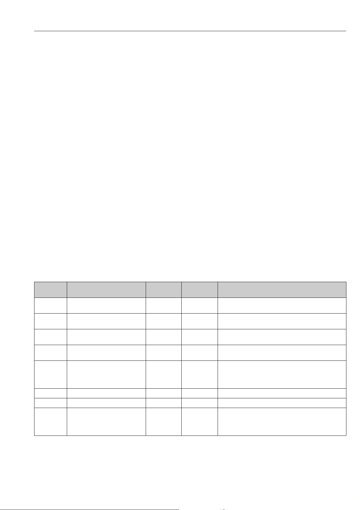
Proline Promass 80 PROFIBUS PA Commissioning
6.6.4 Configuration examples with Simatic S7 HW-Konfig
Example 1:
Fig. 31: Complete configuration using the Promass 80 GSD file.
It is essential to adhere to the following sequence when configuring the modules in the
PROFIBUS master (Class 1):
Slot
sequence
1AI 5–Analog Input function block 1
2AI 5–Analog Input function block 2
3AI 5–Analog Input function block 3
4AI 5–Analog Input function block 4
5 SETTOT_MODETOT_TOTAL 5 2
6 DISPLAY_VALUE – 5 Default value for local display
7 CONTROL_BLOCK – 1 Control of device functions
8 SETTOT_MODETOT_TOTAL 5 2
Module
Byte length
input data
Byte length
output data
Description
Output variable mass flow (factory setting)
Output variable volume flow (factory setting)
Output variable corrected volume flow (factory setting)
Output variable density (factory setting)
Totalizer function block 1
TOTAL output variable = totalized mass flow (factory setting)
SETTOT totalizer control
MODETOT totalizer configuration
Totalizer function block 2
TOTAL output variable = totalized mass flow (factory setting)
SETTOT totalizer control
MODETOT totalizer configuration
a0004775
Endress+Hauser 59
Page 60
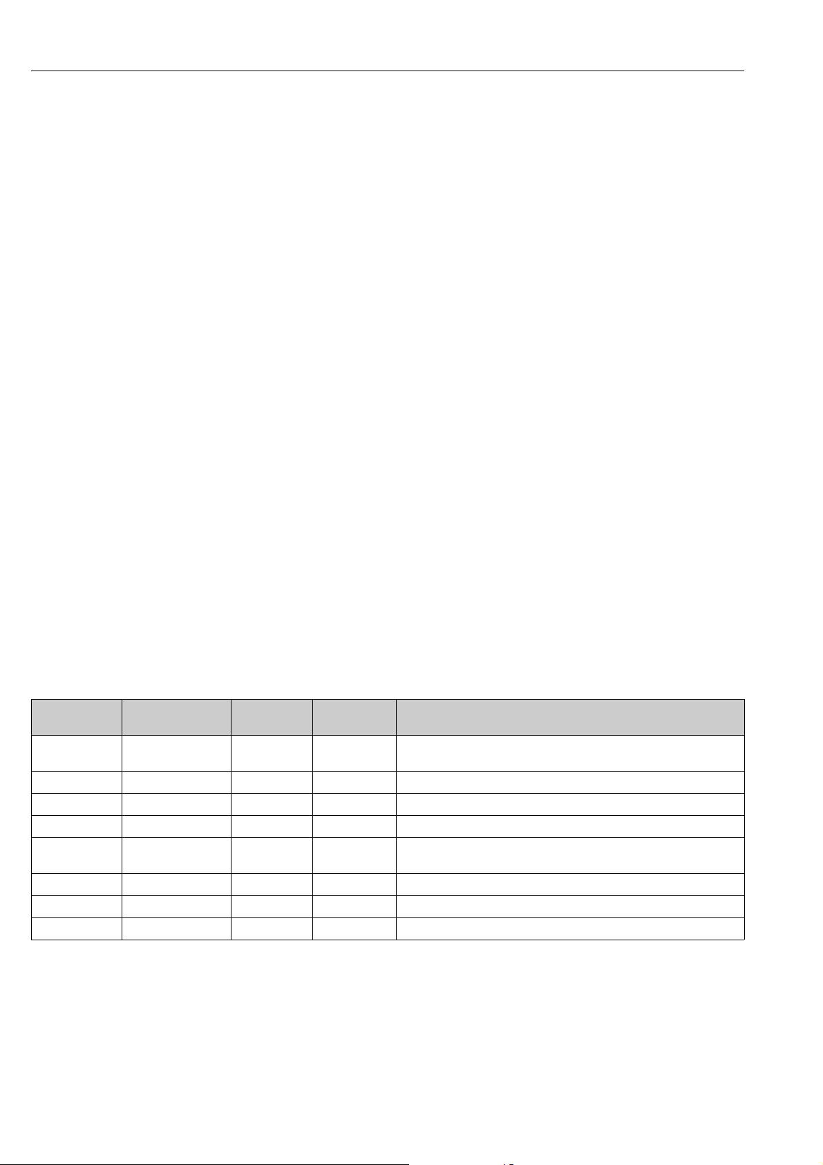
Commissioning Proline Promass 80 PROFIBUS PA
Example 2:
Fig. 32: In this configuration example, modules that are not needed are replaced by the module EMPTY_MODULE.
The Promass 80 GSD file is used.
With this configuration, the Analog Input function block 1 (slot 1), the totalizer value TOTAL
(slot 5) and the cyclic control of device functions CONTROL_BLOCK (slot 7) are activated. The
mass flow (factory setting) is read out cyclically by the measuring device by means of the Analog
Input function block 1. The totalizer is configured "without configuration". In other words, in this
example it only returns the totalizer value for the mass flow (factory setting) by means of the TOTAL
module and cannot be controlled by the PROFIBUS master (Class 1).
Slot sequence Module
1AI5–Analog Input function block 1
2 EMPTY_MODULE – – Empty
3 EMPTY_MODULE – – Empty
4 EMPTY_MODULE – – Empty
5TOTAL5–
6 EMPTY_MODULE – – Empty
7 CONTROL_BLOCK – 1 Control of device functions
8 EMPTY_MODULE – – Empty
Byte length
input data
Byte length
output data
Description
Output variable mass flow (factory setting)
Totalizer function block 1
TOTAL output variable = totalized mass flow (factory setting)
a0004791
60 Endress+Hauser
Page 61
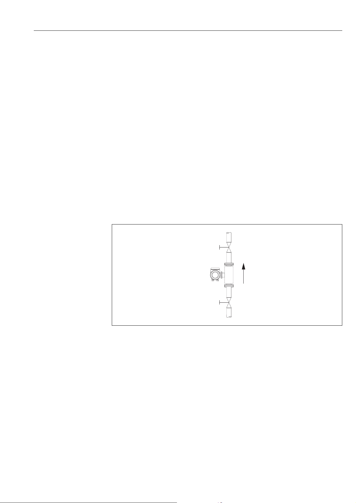
Proline Promass 80 PROFIBUS PA Commissioning
1
2
6.7 Adjustment
6.7.1 Zero point adjustment
All measuring devices are calibrated with state-of-the-art technology. The zero point obtained in
this way is printed on the nameplate.
Calibration takes place under reference operating conditions ä 92.
Consequently, the zero point adjustment is generally not necessary!
Experience shows that the zero point adjustment is advisable only in special cases:
• To achieve highest measuring accuracy also with very small flow rates.
• Under extreme process or operating conditions (e.g. very high process temperatures or very high
viscosity fluids).
Preconditions for a zero point adjustment
Note the following before you perform a zero point adjustment:
• A zero point adjustment can be performed only with fluids that have no gas or solid contents.
• Zero point adjustment is performed with the measuring tubes completely filled and at zero flow
(v = 0 m/s). This can be achieved, for example, with shutoff valves upstream and/or downstream
of the sensor or by using existing valves and gates.
– Normal operation valves 1 and 2 open
– Zero point adjustment with pump pressure Valve 1 open / valve 2 closed
– Zero point adjustment without pump pressure Valve 1 closed / valve 2 open
a0003601
Fig. 33: Zero point adjustment and shutoff valves
Caution!
"
• If the fluid is very difficult to measure (e.g. containing entrained solids or gas) it may prove
impossible to obtain a stable zero point despite repeated zero point adjustments. In instances of
this nature, please contact your E+H service center.
• You can view the currently valid zero point value using the ZERO POINT function (see the
"Description of Device Functions" manual).
Endress+Hauser 61
Page 62
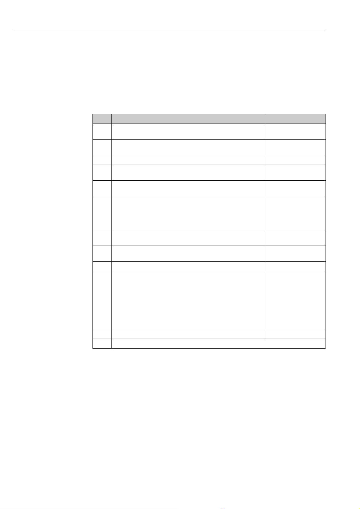
Commissioning Proline Promass 80 PROFIBUS PA
Performing a zero point adjustment
1. Operate the system until operating conditions have settled.
2. Stop the flow (v = 0 m/s).
3. Check the shutoff valves for leaks.
4. Check that operating pressure is correct.
5. Now perform the adjustment as follows:
Key Procedure Display text
HOME position enter the operating matrix > GROUP SELECTION <
F
Select the "PROCESS PARAMETER" function group > GROUP SELECTION <
P
Select the desired function "ZERO ADJUST". ZERO ADJUST CANCEL
N
When you press P you are automatically prompted to enter the access code if
P
the function matrix is still disabled.
Enter code (80 = factory setting) CODE ENTRY
P
Confirm code entry.
F
The "ZERO ADJUST" function then appears again on the display.
Select "START" ZERO ADJUST.
P
Confirm entry with the E-key.
F
A security query appears on the display.
Select "YES" SURE? YES
P
Confirm entry with the E-key. Zero point adjustment is now started. The
message on the right appears on the display for 30 to 60 seconds while zero
point adjustment is in progress.
If the flow in the pipe exceeds 0.1 m/s, the following error message appears on
the display: "ZERO ADJUST NOT POSSIBLE".
F
MEASURED VALUES
PROCESS PARAMETER
CODE ENTRY
***
80
PROGRAMMING
ENABLED
ZERO ADJUST.
CANCEL
START
SURE? NO
ZERO ADJUST.
RUNNING
When the zero point adjustment is completed, the "ZERO ADJUST." function
reappears on the display.
The new zero point value is displayed when the Enter key is pressed. ZERO POINT
F
Press P simultaneously HOME position
Q
ZERO ADJUST.
CANCEL
62 Endress+Hauser
Page 63

Proline Promass 80 PROFIBUS PA Commissioning
6.7.2 Density adjustment
Accuracy when determining the density has a direct effect on volume flow calculation. Density
adjustment is thus necessary under the following conditions:
• The sensor does not measure exactly the density value that the user expects on the basis of
laboratory analyses.
• The fluid properties are outside the measuring points set at the factory, or the reference operating
conditions used to calibrate the measuring device.
• The system is used exclusively to measure a fluid’s density which must be registered to a high
degree of accuracy under constant conditions.
Performing a 1-point density adjustment
Caution!
"
• Onsite density adjustment can be performed only if the user has detailed knowledge of the fluid
density, obtained for example from detailed laboratory analyses.
• The target density value specified in this way must not deviate from the measured fluid density
by more than ±10%.
• An error in defining the target density affects all calculated density and volume functions.
• Density adjustment changes the factory density calibration values or the calibration values set by
the service technician.
• The functions outlined in the following instructions are described in detail in the "Description of
Device Functions" manual.
1. Fill the sensor with fluid. Make sure that the measuring tubes are completely filled and that
liquids are free of gas bubbles.
2. Wait until the temperature difference between fluid and measuring tube has equalized. The
time you have to wait for equalization depends on the fluid and the temperature level.
3. Select the density adjustment function:
HOME F R PROCESS PARAMETERS F DENSITY SET POINT
– When you press P you are automatically prompted to enter the access code if the function
matrix is still disabled. Enter the code.
–Now use P to enter the target density of your fluid and press F to save this value (input
range = actual density value ±10%).
4. Press F to select the "MEASURE FLUID" function.
With P, select the "START" setting and press F. The message "DENSITY ADJUST RUNNING"
then appears on the display for approx. 10 seconds. During this time Promass measures the
current density of the fluid (actual density value).
5. Press F to select the "DENSITY ADJUST" function.
With P, now select the "DENSITY ADJUST" setting and press F. Promass now compares the
target and actual density values and uses this information to calculate the new density
coefficients.
Caution!
"
If the density adjustment does not complete correctly, you can select the RESTORE ORIGINAL
function to reactivate the default density coefficients.
6. Back to HOME position with Q (press P simultaneously).
Endress+Hauser 63
Page 64

Commissioning Proline Promass 80 PROFIBUS PA
6.8 Rupture disk
Sensor housings with integrated rupture disks are optionally available.
#
!
Warning!
• Make sure that the function and operation of the rupture disk is not impeded through the
installation. Triggering overpressure in the housing as stated on the indication label. Take
adequate precautions to ensure that no damage occurs, and risk to human life is ruled out, if the
rupture disk is triggered. Rupture disk: Burst pressure 10 to 15 bar (145 to 217.5 psi).
• Please note that the housing can no longer assume a secondary containment function if a rupture
disk is used.
• It is not permitted to open the connections or remove the rupture disk.
Caution!
"
• Rupture disks can not be combined with separately available heating jacket (except Promass A).
• The existing connection nozzles are not designed for a rinse or pressure monitoring function.
Note!
• Before commissioning, please remove the transport protection of the rupture disk.
• Please note the indication labels.
6.9 Purge and pressure monitoring connections
#
The sensor housing protects the inner electronics and mechanics and is filled with dry nitrogen.
Beyond that, up to a specified measuring pressure it additionally serves as secondary containment.
Warning!
For a process pressure above the specified containment pressure, the housing does not serve as an
additional secondary containment. In case a danger of measuring tube failure exists due to process
characteristics, e.g. with corrosive process fluids, we recommend the use of sensors whose housing
is equipped with special pressure monitoring connections (ordering option). With the help of these
connections, fluid collected in the housing in the event of tube failure can be drained off. This
diminishes the danger of mechanical overload of the housing, which could lead to a housing failure
and accordingly is connected with an increased danger potential. These connections can also be
used for gas purging (gas detection).
The following instructions apply to handling sensors with purge or pressure monitoring connections:
• Do not open the purge connections unless the containment can be filled immediately with a dry
inert gas.
• Use only low gauge pressure to purge. Maximum pressure 5 bar (72.5 psi).
6.10 Data storage device (HistoROM)
At Endress+Hauser, the term HistoROM refers to various types of data storage modules on which
process and measuring device data are stored. By plugging and unplugging such modules, device
configurations can be duplicated onto other measuring devices to cite just one example.
6.10.1 HistoROM/S–DAT (sensor–DAT)
The S-DAT is an exchangeable data storage device in which all sensor relevant parameters are
stored, i.e., diameter, serial number, calibration factor, zero point.
64 Endress+Hauser
Page 65

Proline Promass 80 PROFIBUS PA Maintenance
7 Maintenance
No special maintenance work is required.
7.1 Exterior cleaning
When cleaning the exterior of measuring devices, always use cleaning agents that do not attack the
surface of the housing and the seals.
7.2 Cleaning with pigs (Promass H, I, S, P)
If pigs are used for cleaning, it is essential to take the inside diameters of measuring tube and process
connection into account. Technical Information ä 87.
7.3 Replacing seals
Under normal circumstances, fluid wetted seals of the Promass A sensor do not require replacement.
Replacement is necessary only in special circumstances, for example if aggressive or corrosive fluids
are incompatible with the seal material.
!
Note!
• The period between changes depends on the fluid properties and on the frequency of cleaning
cycles in the case of CIP/SIP cleaning.
• Replacement seals (accessories)
Endress+Hauser 65
Page 66
Accessories Proline Promass 80 PROFIBUS PA
8Accessories
Various accessories , which can be ordered separately from Endress+Hauser, are available for the
transmitter and the sensor. The Endress+Hauser service organization can provide detailed
information on the order code of your choice.
8.1 Device-specific accessories
Accessory Description Order code
Proline Promass 80
transmitter
8.2 Measuring principle-specific accessories
Transmitter for replacement or for stock. Use the order
code to define the following specifications:
–Approvals
– Degree of protection / version
– Cable entries
– Display / power supply / operation
–Software
– Outputs / inputs.
80XXX – XXXXX * * * * * *
Accessory Description Order code
Mounting set for
transmitter
Post mounting set for the
Promass A sensor
Mounting set for the
Promass A sensor
Set of seals for sensor For regular replacement of the seals of the Promass A
Memograph M graphic
display recorder
Mounting kit for wall-mount housing (remote version).
Suitable for:
– Wall mounting
– Pipe mounting
– Panel mounting
Mounting set for aluminum field housing:
Suitable for pipe mounting (¾" to 3")
Post mounting set for the Promass A DK8AS – * *
Mounting set for Promass A, comprising:
– 2 process connections
–Seals
sensor.
Set consists of two seals.
The Memograph M graphic display recorder provides
information on all the relevant process variables.
Measured values are recorded correctly, limit values are
monitored and measuring points analyzed. The data are
stored in the 256 MB internal memory and also on a DSD
card or USB stick.
Memograph M boasts a modular design, intuitive
operation and a comprehensive security concept. The
®
ReadWin
package and is used for configuring, visualizing and
archiving the data captured.
The mathematics channels which are optionally available
enable continuous monitoring of specific power
consumption, boiler efficiency and other parameters
which are important for efficient energy management.
2000 PC software is part of the standard
DK8WM – *
DK8MS – * * * * * *
DKS – * * *
RSG40 - ************
66 Endress+Hauser
Page 67
Proline Promass 80 PROFIBUS PA Accessories
8.3 Service-specific accessories
Accessory Description Order code
Applicator Software for selecting and configuring Endress+Hauser
flowmeters:
• Calculating all necessary data to determine the optimal
flowmeter: e.g. nominal diameter, pressure drop,
performance characteristics or process connections
• Graphic display of calculation results
Management, documentation and retrievability of all
project-related data and parameters of the entire
operating life of a project.
Applicator is available:
• Via the Internet: https://wapps.endress.com/
applicator
• On CD-ROM for installation on local computer
Fieldcheck Tester/simulator for testing flowmeters in the field.
When used in conjunction with the "FieldCare" software
package, test results can be imported into a database,
printed and used for official certification.
Contact your Endress+Hauser representative for more
information.
DKA80 - *
50098801
FieldCare FieldCare is Endress+Hauser’s FDT-based plant asset
management tool. It can configure all intelligent field
units in your system and helps you manage them. By
using the status information, it is also a simple but
effective way of checking their status and condition.
FXA193 The FXA193 service interface connects the device to the
PC for configuration via FieldCare.
See the product page on the
Endress+Hauser Web site:
www.endress.com
FXA193 – *
Endress+Hauser 67
Page 68
Troubleshooting Proline Promass 80 PROFIBUS PA
9Troubleshooting
9.1 Troubleshooting instructions
Always start troubleshooting with the following checklist if faults occur after commissioning or
during operation. The routine takes you directly to the cause of the problem and the appropriate
remedial measures.
Check the display
No display visible and no
output signals present.
No display visible, but
output signals are present.
Display texts are in a
foreign language.
Measured value indicated,
but no signal at the current
or pulse output
▼
Error messages on display
Errors that occur during commissioning or measuring are displayed immediately. Error messages consist of a variety of
icons. The meanings of these icons are as follows (example):
– Error type: S = system error, P = process error
– Error message type: $ = fault message, ! = notice message
– MEDIUM INHOM. = error designation (e.g. fluid is not homogeneous)
– 03:00:05 = duration of error occurrence (in hours, minutes and seconds)
– #702 = error number
Caution!
"
Also refer to the information ä 40
System error (device error) has occurred ä 70
Process error (application error) has occurred ä 76
▼
Faulty connection to control system
No connection can be made between the control system and the device.
Check the following points:
Supply voltage
Transmitter
Device fuse Check device fuse ä 84
Fieldbus connection Check the data cable
Fieldbus connector • Check pin assignment/wiring ä 24
Fieldbus voltage Check that a min. bus voltage of 9 V DC is present at terminals 26/27. Permissible range: 9
1. Check the supply voltage Terminals 1, 2
2. Check device fuse ä 84
85 to 260 V AC: 0.8 A slow-blow / 250 V
20 to 55 V AC and 16 to 62 V DC:2 A slow-blow / 250 V
3. Measuring electronics defective order spare parts ä 79
1. Check whether the ribbon-cable connector of the display module is correctly plugged
into the amplifier board Page 79 ff.
2. Display module defective order spare parts ä 79
3. Measuring electronics defective order spare parts ä 79
Switch off power supply. Press and hold down both the P keys and switch on the
measuring device. The display text will appear in English (default) and is displayed at
maximum contrast.
Measuring electronics defective order spare parts ä 79
Check the supply voltage Terminals 1/2
85 to 260 V AC: 0.8 A slow-blow / 250 V
20 to 55 V AC and 16 to 62 V DC: 2 A slow-blow / 250 V
Terminal 26 = PA +
Terminal 27 = PA
• Check connection between connector/fieldbus port.
Is the coupling ring tightened correctly?
to 32 V DC
68 Endress+Hauser
Page 69
Proline Promass 80 PROFIBUS PA Troubleshooting
Network structure Check permissible fieldbus length and number of spurs. ä 25
Basic current Is there a basic current of min. 11 mA?
Bus address Check bus address: make sure there are no double assignments
Bus termination
(Termination)
Current consumption,
permissible feed current
▼
System or process error messages
System or process errors which occur during commissioning or operation can be displayed via the local display or an
operating program (e.g. FieldCare) in the ACTUAL SYSTEM CONDITION function.
▼
Other error (without error message)
Some other error has
occurred.
Has the PROFIBUS network been terminated correctly?
Each bus segment must always be terminated with a bus terminator at both ends (start and
finish). Otherwise there may be interference in communication.
Check the current consumption of the bus segment:
The current consumption of the bus segment in question (= total of basic currents of all bus
users) must not exceed the max. permissible feed current of the bus power supply.
Diagnosis and rectification ä 78
Endress+Hauser 69
Page 70
Troubleshooting Proline Promass 80 PROFIBUS PA
Quality
Code
Measuring value
Limits
Quality Substatus
Quality
Status
Byte 5
9.2 System error messages
Serious system errors are always recognized by the instrument as "Fault message" and are shown
as a lightning flash ($) on the display! Fault messages immediately affect the outputs. Simulations
and positive zero return, on the other hand, are classed and displayed as "Notice messages".
Caution!
"
In the event of a serious fault, a flowmeter might have to be returned to the manufacturer for repair.
Important procedures must be carried out before you return a flowmeter to Endress+Hauser
ä 85.
Always enclose a duly completed "Declaration of contamination" form. You will find a preprinted
blank of this form at the back of this manual.
!
Note!
See the information ä 40.
9.2.1 Displaying the device status on PROFIBUS PA
Display in the operating program (acyclic data transmission)
The device status can be queried using an operating program (e.g. FieldCare):
Function block SUPERVISION SYSTEM OPERATION ACTUAL SYSTEM CONDITION
Display in the PROFIBUS master system (cyclic data transmission)
If the AI or TOTAL modules are configured for cyclic data transmission, the device status is coded
in accordance with PROFIBUS Profile Specification 3.0 and transmitted with the measured value to
the PROFIBUS master (Class 1) by means of the quality byte (byte 5). The quality byte is split into
the "quality status", "quality substatus" and "limits" segments.
a0002707-en
Fig. 34: Structure of the quality byte
The content of the quality byte depends on the failsafe mode error behavior configured in the
corresponding Analog Input function block. Depending on which failsafe mode has been set in the
FAILSAFE_TYPE function, the following status information is transmitted to the PROFIBUS master
(Class 1) via the quality byte:
• For FAILSAFE_TYPE FSAFE VALUE:
Quality code (HEX) Quality status Quality substatus Limits
0x48
0x49
0x4A
UNCERTAIN Substitute set
OK
Low
High
70 Endress+Hauser
Page 71
Proline Promass 80 PROFIBUS PA Troubleshooting
• For FAILSAFE_TYPE LAST GOOD (factory setting):
If a valid output value was available before the failure:
Quality code (HEX) Quality status Quality substatus Limits
0x44
0x45
0x46
UNCERTAIN Last usable value
OK
Low
High
If no valid output value was available before the failure:
Quality code (HEX) Quality status Quality substatus Limits
0x4C
0x4D
0x4E
UNCERTAIN Initial Value
OK
Low
High
• For FAILSAFE_TYPE WRONG VALUE:
For status information, see the table in the following section.
!
Note!
The FAILSAFE_TYPE function can be configured in the corresponding Analog Input function block
1 to 6 or Totalizer function block 1 to 3 by means of an operating program (e.g. FieldCare).
9.2.2 List of system error messages
PROFIBUS measured value status
No. Device status message
(local display)
Quality status
Quality code (HEX)
Measured value status
Depicted on the local display:
S = System error
= Fault message (with an effect on the outputs)
$
! = Notice message (without any effect on the outputs)
001 S: CRITICAL FAILURE
: # 001
$
011 S: AMP HW EEPROM
: # 011
$
012 S: AMP SW EEPROM
: # 012
$
0x0F BAD Device Failure Constant ROM / RAM
0x0F BAD Device Failure Constant Amplifier EEPROM
0x0F BAD Device Failure Constant Amplifier EEPROM
Limits
Quality substatus
Extended
diagnostic
message in the
PROFIBUS
master
failure
failure
data inconsistent
Cause/remedy (spare part ä 79)
Cause:
ROM/RAM error. Error when accessing the
program memory (ROM) or random access
memory (RAM) of the processor.
Remedy:
Replace the amplifier board.
Cause:
Amplifier with faulty EEPROM
Remedy:
Replace the amplifier board.
Cause:
Error when accessing data of the measuring
amplifier EEPROM
Remedy:
Perform a "warm start" (= start the measuring
system without disconnecting main power).
Access:
SUPERVISION SYSTEM OPERATION
SYSTEM RESET ( RESTART)
Endress+Hauser 71
Page 72
Troubleshooting Proline Promass 80 PROFIBUS PA
PROFIBUS measured value status
Extended
No. Device status message
(local display)
031 S: SENSOR HW DAT
: # 031
$
032 S: SENSOR SW DAT
: # 032
$
121 S: A/C COMPATIB.
!: # 121
261 S: COMMUNICAT. I/O
: # 261
$
379 S: LOW FREQ. LIM
: # 379
$
Quality status
Quality code (HEX)
Measured value status
0x10
0x11
0x12
0x10
0x11
0x12
0x0F BAD Device Failure Constant Amplifier and I/O
0x18
0x19
0x1A
0x0F BAD Device Failure Constant Frequence limit 1 Cause:
BAD Sensor Failure O.K.
BAD Sensor Failure O.K.
BAD No
Quality substatus
Communicati
on
Low
High
Low
High
O.K.
Low
High
diagnostic
message in the
PROFIBUS
Limits
master
S-DAT failure /
S-DAT not inserted
S-DAT data
inconsistent
board only partially
compatible
Communication
failure
Cause/remedy (spare part ä 79)
Cause:
1. S-DAT is not plugged into the amplifier board
correctly (or is missing).
2. S-DAT is defective.
Remedy:
1. Check whether the S-DAT is correctly plugged
into the amplifier board.
2. Replace the S-DAT if it is defective.
Check that the new, replacement DAT is
compatible with the measuring electronics.
Check the:
- Spare part set number
- Hardware revision code
3. Replace measuring electronics boards if
necessary.
4. Plug the S-DAT into the amplifier board.
Cause:
Due to different software versions, I/O board and
amplifier board are only partially compatible
(possibly restricted functionality).
Note!
!
• This message is only listed in the error history.
• Nothing is displayed on the display.
Remedy:
Module with lower software version has either to
be actualized by FieldCare with the required
software version or the module has to be replaced.
Cause:
Communication error. No data reception between
amplifier and I/O board or faulty internal data
transfer.
Remedy:
Check whether the electronics boards are correctly
inserted in their holders
The measuring tube oscillation frequency is outside
the permitted range.
Causes:
Measuring tube damaged
Sensor defective or damaged
Remedy:
Contact your Endress+Hauser service organization.
72 Endress+Hauser
Page 73

Proline Promass 80 PROFIBUS PA Troubleshooting
PROFIBUS measured value status
Extended
No. Device status message
(local display)
380 S: UPPER FREQ. LIM
: # 380
$
Quality status
Quality code (HEX)
Measured value status
0x0F BAD Device Failure Constant Frequence limit 2 Cause:
Quality substatus
diagnostic
message in the
PROFIBUS
Limits
master
Cause/remedy (spare part ä 79)
The measuring tube oscillation frequency is outside
the permitted range.
Causes:
Measuring tube damaged
Sensor defective or damaged
Remedy:
Contact your Endress+Hauser service organization.
381 S: FLUIDTEMP.MIN.
: # 381
$
382 S: FLUIDTEMP.MAX.
: # 382
$
383 S: CARR.TEMP.MIN
: # 383
$
384 S: CARR.TEMP.MAX
: # 384
$
385 S: INL.SENS.DEF.
: # 385
$
386 S: OUTL.SENS.DEF.
: # 386
$
387 S: SEN.ASY.EXCEED
: # 387
$
388 S: AMP. FAULT
: # 388
$
389 S: AMP. FAULT
: # 389
$
390 S: AMP. FAULT
: # 390
$
0x10
0x11
0x12
0x10
0x11
0x12
0x10
0x11
0x12
0x10
0x11
0x12
0x10
0x11
0x12
0x10
0x11
0x12
0x10
0x11
0x12
0x0F BAD Device Failure Constant Amplifier failure Cause:
0x0F BAD Device Failure Constant Amplifier failure
0x0F BAD Device Failure Constant Amplifier failure
BAD Sensor Failure O.K.
Low
High
BAD Sensor Failure O.K.
Low
High
BAD Sensor Failure O.K.
Low
High
BAD Sensor Failure O.K.
Low
High
BAD Sensor Failure O.K.
Low
High
BAD Sensor Failure O.K.
Low
High
BAD Sensor Failure O.K.
Low
High
Fluid Temperature
Min.
Fluid Temperature
Max.
Carrier
Temperature Min.
Carrier
Temperature Max.
Inlet Sensor
Defect
Outlet Sensor
Defect
Sensor Asymmetry
Exceeded
Cause:
The temperature sensor on the measuring tube is
likely defective.
Remedy:
Check the following electrical connections before
you contact your Endress+Hauser service
organization:
• Verify that the sensor signal cable connector is
correctly plugged into the amplifier board
• Remote version: Check sensor and transmitter
terminal connections No. 9 and 10 ä 28
Cause:
The temperature sensor on the carrier tube is likely
defective.
Remedy:
Check the following electrical connections before
you contact your Endress+Hauser service
organization:
• Verify that the sensor signal cable connector is
correctly plugged into the amplifier board
• Remote version: Check sensor and transmitter
terminal connections No. 11 and 12 ä 28
Cause:
One of the measuring tube sensor coils
(inlet or outlet) is likely defective.
Remedy:
Check the following electrical connections before
you contact your Endress+Hauser service
organization:
Verify that the sensor signal cable connector is
•
correctly plugged into the amplifier board
• Remote version: Check sensor and transmitter
terminal connections No. 4, 5, 6, 7.
Amplifier error
Remedy:
Contact your Endress+Hauser service organization.
Endress+Hauser 73
Page 74

Troubleshooting Proline Promass 80 PROFIBUS PA
PROFIBUS measured value status
Extended
No. Device status message
(local display)
501 S: SW.-UPDATE ACT.
!: # 501
Quality status
Quality code (HEX)
Measured value status
0x48
UNCERTAIN Substitute set
0x49
0x4A
Quality substatus
(Substitute set
of failsafe
status)
O.K.
Low
High
diagnostic
message in the
PROFIBUS
Limits
master
New amplifier
software loaded
Cause/remedy (spare part ä 79)
Cause:
New amplifier or communication software version
is loaded.
Currently no other functions are possible.
Remedy:
Wait until process is finished. The device will
restart automatically.
502 S: UP-/DOWNLO. ACT.
!: # 502
586 P: OSC. AMP. LIMIT
: # 586
$
587 P: TUBE NOT OSC
: # 587
$
588 P: GAIN RED.IMPOS
: # 588
$
0x48
UNCERTAIN Substitute set
0x49
0x4A
0x10
0x11
0x12
0x10
0x11
0x12
0x10
0x11
0x12
BAD Sensor Failure O.K.
BAD Sensor Failure O.K.
BAD Sensor Failure O.K.
(Substitute set
of failsafe
status)
O.K.
Low
High
Low
High
Low
High
Low
High
Upload/download
of device data
active
Oscillation
amplitude too low
No oscillation
possible
Gain reduction
impossible
Cause:
Up- or downloading the device data via operating
program. Currently no other functions are possible.
Remedy:
Wait until process is finished.
Cause:
The fluid properties do not allow a continuation of
the measurement.
Causes:
Extremely high viscosity
Fluid is very inhomogeneous (gas or solid content)
Remedy:
Change or improve process conditions.
Cause:
Extreme process conditions exist. The measuring
system can therefore not be started.
Remedy:
Change or improve process conditions.
Cause:
Overdriving of the internal analog to digital
converter.
A continuation of the measurement is no longer
possible!
Causes:
Cavitation
Extreme pressure shock
igh gas flow velocity
H
Remedy:
Change or improve process conditions, e.g. by
reducing the flow velocity.
601 S: POS. ZERO-RETURN
!: # 601
0x53 UNCERTAIN Sensor
conversion
not accurate
(measured
value from
sensor not
accurate)
Constant Positive zero return
active
Cause:
Positive zero return is active
Remedy:
Switch off positive zero return:
Access:
BASIC FUNCTIONS SYSTEM PARAMETER
CONFIGURATION POS. ZERO RETURN
( OFF)
74 Endress+Hauser
Page 75
Proline Promass 80 PROFIBUS PA Troubleshooting
PROFIBUS measured value status
Extended
No. Device status message
(local display)
691 S: SIM. FAILSAFE
!: # 691
692 S: SIM. MEASURAND
!: # 692
698 S: DEV. TEST ACT.
!: # 698
Quality status
Quality code (HEX)
Measured value status
0x48
UNCERTAIN Substitute set
0x49
0x4A
0x60
UNCERTAIN Simulated
0x61
0x62
0x60
UNCERTAIN Simulated
0x61
0x62
Quality substatus
(Substitute set
of failsafe
status)
Value
(manually
specified
value)
Value
(manually
specified
value)
O.K.
Low
High
O.K.
Low
High
O.K.
Low
High
diagnostic
message in the
PROFIBUS
Limits
master
Simulation failsafe
active
Simulation
measured value
active
Device test via
Fieldcheck active
Cause/remedy (spare part ä 79)
Cause:
Simulation of response to error is active.
Remedy:
Switch off simulation:
Access:
SUPERVISION SYSTEM OPERATION
SIM. FAILSAFE MODE ( OFF)
Cause:
Simulation is active
Remedy:
Switch off simulation:
Access:
SUPERVISION SYSTEM OPERATION
SIM. MEASURAND ( OFF)
Cause:
The measuring device is being checked on site via
the test and simulation device.
Endress+Hauser 75
Page 76
Troubleshooting Proline Promass 80 PROFIBUS PA
9.3 Process error messages
!
Note!
See the information ä 40
9.3.1 Displaying the device status on PROFIBUS PA
Further information ä 70
9.3.2 List of process error messages
PROFIBUS measured value status
No. Device status message
(local display)
Quality status
Quality code (HEX)
Measured value status
P = Process error
= Fault message (with an effect on the outputs)
$
! = Notice message (without any effect on the outputs)
700 P: EMPTY PIPE
!: # 700
0x53 UNCERT
AIN
Quality substatus
Sensor
conversion
not accurate
(measured
value from
sensor not
accurate)
Extended
diagnostic
message in the
PROFIBUS
Limits
master
Constant Empty pipe
detected
Cause/remedy
Cause:
The process fluid density is outside the upper or lower
limit values set for empty pipe detection.
Causes:
Air in the measuring tube Partly filled measuring tube
Remedy:
1. Ensure that there is no gas content in the process
liquid.
2. Adjust the upper or lower limit value for empty
pipe detection to the current process conditions.
Access:
BASIC FUNCTIONS PROCESS PARAMETER
EPD PARAMETER EPD VALUE LOW or EPD
VALUE HIGH
701 P: EXC. CURR. LIM
!: # 701
0x40
0x41
0x42
UNCERT
AIN
Non specific
(uncertain
status)
O.K.
Low
High
Excitation too high Cause:
The maximum current value for the sensor coils has
been reached, since certain process fluid characteristics
are extreme, e.g. high gas or solid content.
The instrument continues to work correctly.
Remedy:
In particular with outgassing fluids and/or increased
gas content, the following measures are recommended
to increase system pressure:
– Install the instrument at the outlet side of a pump.
– Install the instrument at the lowest point of an
ascending pipeline.
– Install a flow restriction, e.g. reducer or orifice plate,
downstream from the instrument.
76 Endress+Hauser
Page 77
Proline Promass 80 PROFIBUS PA Troubleshooting
PROFIBUS measured value status
Extended
No. Device status message
(local display)
702 P: MEDIUM INHOM.
!: # 702
703 P: NOISE LIM. CH0
!: # 703
704 P: NOISE LIM. CH1
!: # 704
705 P: FLOW LIMIT
: # 705
$
731 P: ADJ. ZERO FAIL
!: # 731
Quality status
Quality code (HEX)
Measured value status
0x43 UNCERT
AIN
0x40
UNCERT
0x41
0x42
0x40
0x41
0x42
0x42 UNCERT
0x43 UNCERT
AIN
UNCERT
AIN
AIN
AIN
Quality substatus
Non specific
(uncertain
status)
Non specific
(uncertain
status)
Non specific
(uncertain
status)
Non specific
(uncertain
status)
Non specific
(uncertain
status)
Constant Fluid
O.K.
Low
High
O.K.
Low
High
High
Limited
Constant Zero point
diagnostic
message in the
PROFIBUS
Limits
master
inhomogeneous
Noise Limit
Channel 0
Noise Limit
Channel 1
Flow limit Cause:
adjustment failure
Cause/remedy
Cause:
Frequency control is not stable, due to inhomogeneous
process fluid, e.g. gas or solid content.
Remedy:
In particular with outgassing fluids and/or increased
gas content, the following measures are recommended
to increase system pressure:
– Install the instrument at the outlet side of a pump.
– Install the instrument at the lowest point of an
ascending pipeline.
– Install a flow restriction, e.g. reducer or orifice plate,
downstream from the instrument.
Cause:
Overdriving of the internal analog to digital converter.
Causes:
Cavitation
Extreme pressure pulses
High gas flow velocity
A continuation of the measurement is still possible!
Remedy:
Change or improve process conditions, e.g. by
reducing the flow velocity.
The mass flow is too high. The electronics' measuring
range will be exceeded.
Remedy:
Reduce flow
Cause:
The zero point adjustment is not possible or has been
canceled.
Remedy:
Make sure that zero point adjustment is carried out at
"zero flow" only (v = 0 m/s) ä 61
Endress+Hauser 77
Page 78
Troubleshooting Proline Promass 80 PROFIBUS PA
9.4 Process errors without messages
Symptoms Rectification
Note!
!
You may have to change or correct certain settings of the function matrix in order to rectify faults. The functions outlined below are described in detail in the
"Description of Device Functions" manual.
Measured value reading fluctuates even
though flow is steady.
Measured value reading shown on
display, even though the fluid is at a
standstill and the measuring tube is full.
The fault cannot be rectified or some
other fault not described above has
occurred.
In these instances, please contact your
Endress+Hauser service organization.
1. Check the fluid for presence of gas bubbles.
2. Increase the following values:
– Analog Input function block RISING TIME
–BASIC FUNCTIONS SYSTEM PARAMETER CONFIGURATION FLOW DAMPING
3. Increase the value for display damping:
HOME USER INTERFACE CONTROL BASIC CONFIG. DISPLAY DAMPING
1. Check the fluid for presence of gas bubbles.
2. Enter a value for the low flow cut off or increase this value:
BASIC FUNCTION PROCESS PARAMETER CONFIGURATION ON-VALUE LF CUTOFF
The following options are available for tackling problems of this nature:
Request the services of an Endress+Hauser service technician
If you contact our service organization to have a service technician sent out, please be ready with the following
information:
• Brief description of the fault
• Nameplate specifications: order code and serial number ä 7
Return devices to Endress+Hauser
You can return a measuring device to Endress+Hauser for repair or calibration.
Always enclose the duly completed "Declaration of contamination" form with the flowmeter. You will find a preprinted
blank of this form at the back of this manual.
Replace transmitter electronics
Parts of the measuring electronics defective Order spare parts ä 79
78 Endress+Hauser
Page 79
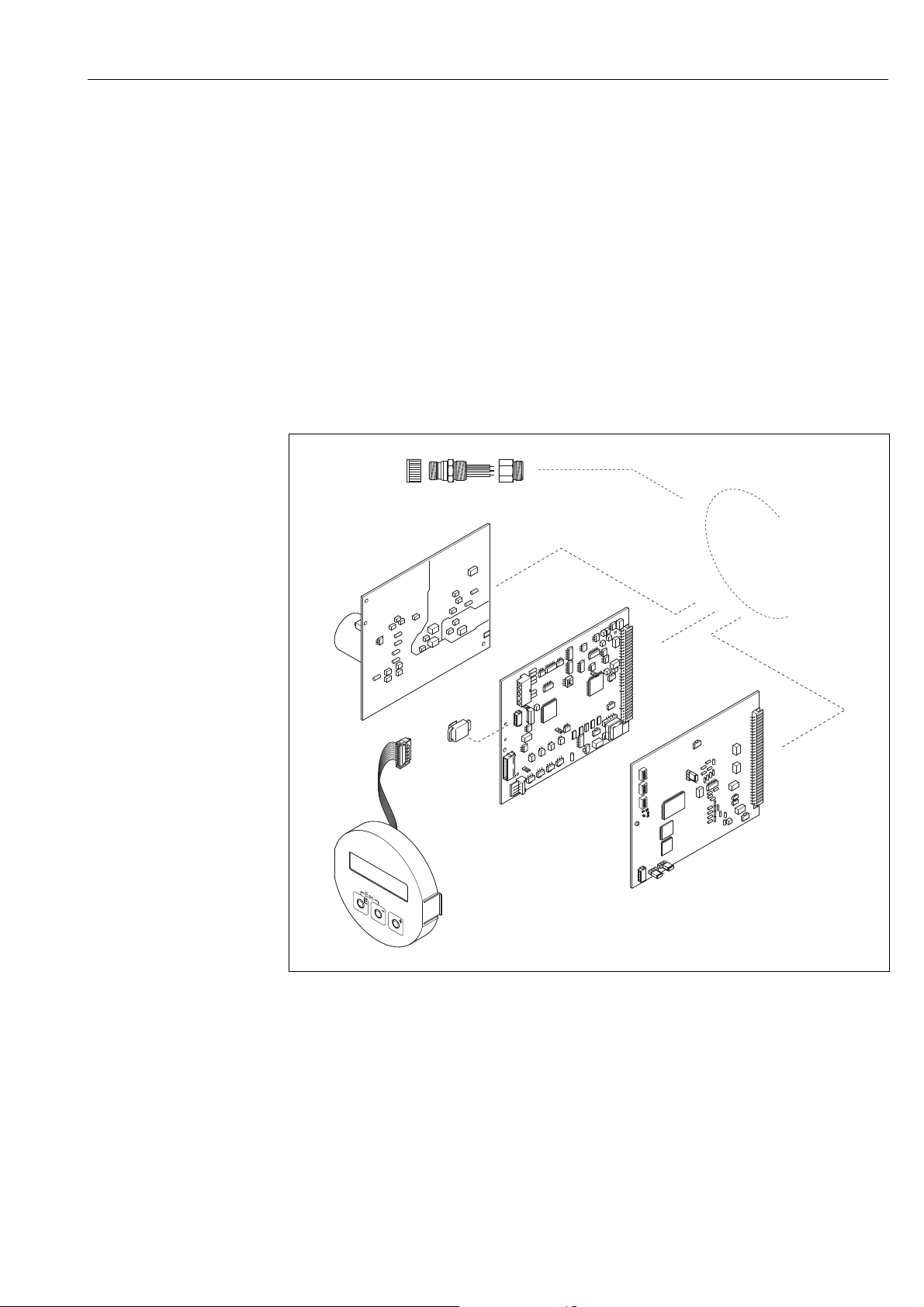
Proline Promass 80 PROFIBUS PA Troubleshooting
1
2
3
5
4
6
9.5 Spare parts
The previous sections contain a detailed troubleshooting guide ä 68.
The measuring device, moreover, provides additional support in the form of continuous selfdiagnosis and error messages.
Fault rectification can entail replacing defective components with tested spare parts. The illustration
below shows the available scope of spare parts.
!
Note!
You can order spare parts directly from your Endress+Hauser service organization by providing the
serial number printed on the transmitter's nameplate ä 7.
Spare parts are shipped as sets comprising the following parts:
• Spare part
• Additional parts, small items (screws, etc.)
• Mounting instructions
• Packaging
Fig. 35: Spare parts for PROFIBUS PA transmitters (field and wall-mount housing)
1 Power unit board (85 to 260 V AC, 20 to 55 V AC, 16 to 62 V DC)
2 Amplifier board
3 I/O board (COM module)
4 S-DAT (sensor data storage device)
5 Display module
6 Fieldbus connector consisting of protection cap, connector, adapter PG 13.5/M20.5
(order No. 50098037)
A0005400
Endress+Hauser 79
Page 80

Troubleshooting Proline Promass 80 PROFIBUS PA
9.5.1 Removing and installing printed circuit boards
Field housing
#
"
Warning!
• Risk of electric shock. Exposed components carry dangerous voltages. Make sure that the power
supply is switched off before you remove the cover of the electronics compartment.
• Risk of damaging electronic components (ESD protection). Static electricity can damage electronic
components or impair their operability. Use a workplace with a grounded working surface
purpose-built for electrostatically sensitive devices!
• If you cannot guarantee that the dielectric strength of the device is maintained in the following
steps, then an appropriate inspection must be carried out in accordance with the manufacturer’s
specifications.
Caution!
Use only original Endress+Hauser parts.
å 36, installation and removal:
1. Unscrew cover of the electronics compartment from the transmitter housing.
2. Remove the local display (1) as follows:
– Press in the latches (1.1) at the side and remove the display module.
– Disconnect the ribbon cable (1.2) of the display module from the amplifier board.
3. Remove the screws and remove the cover (2) from the electronics compartment.
4. Remove power unit board (4) and I/O board (6):
Insert a thin pin into the hole provided (3) for the purpose and pull the board clear of its holder.
5. Remove amplifier board (5):
– Disconnect the plug of the sensor signal cable (5.1) including S-DAT (5.3) from the board.
– Gently disconnect the plug of the excitation current cable (5.2) from the board, i.e. without
moving it back and forth.
– Insert a thin pin into the hole provided (3) for the purpose and pull the board clear of its
holder.
6. Installation is the reverse of the removal procedure.
80 Endress+Hauser
Page 81
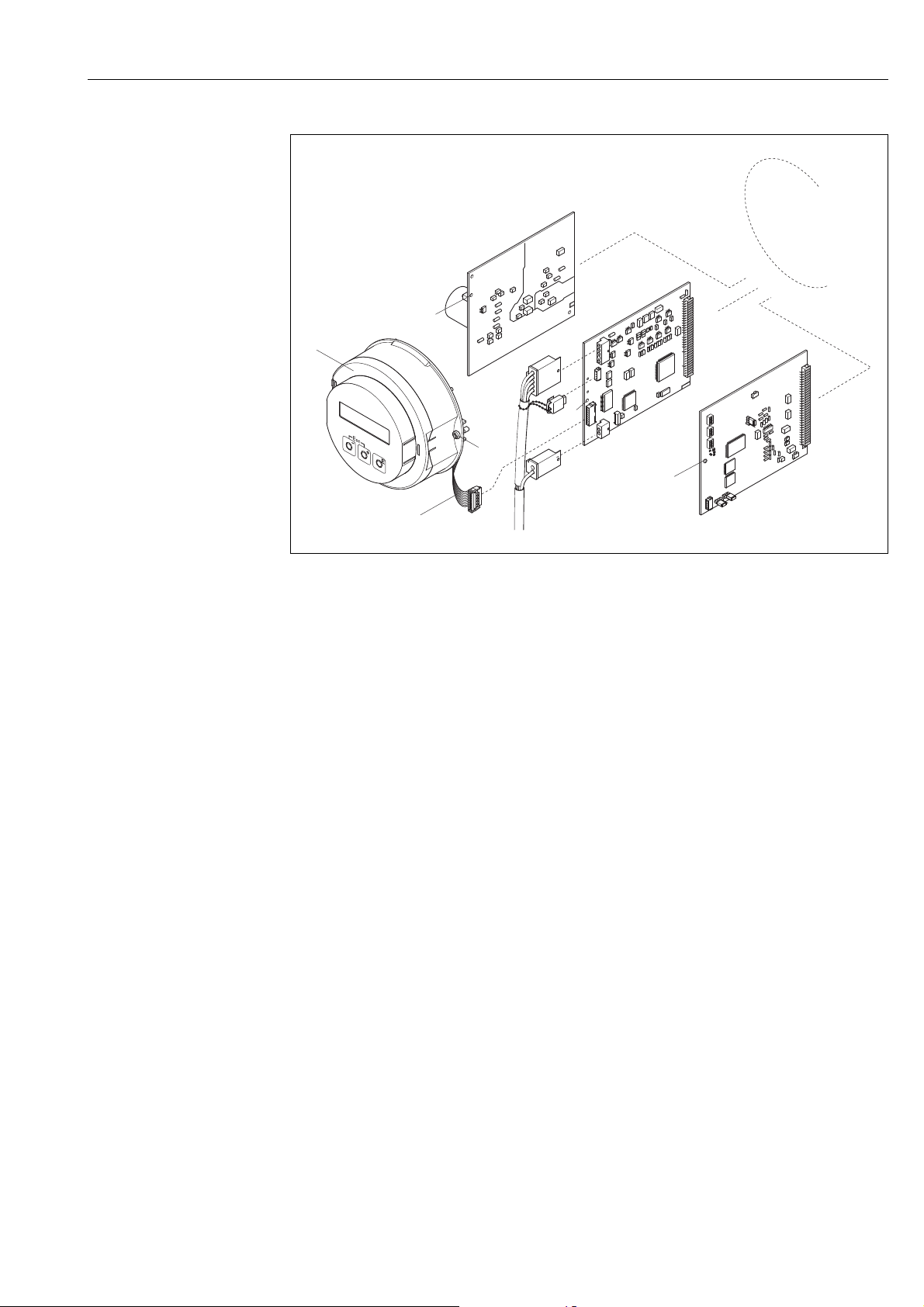
Proline Promass 80 PROFIBUS PA Troubleshooting
3
4
5
2
2
2
4.1
4.3
4.2
1.1
1
1.2
a0004769
Fig. 36: Field housing: removing and installing printed circuit boards
1 Local display
1.1 Latch
1.2 Ribbon cable (display module)
2 Screws of electronics compartment cover
3 Aperture for installing/removing boards
4 Power unit board
5 Amplifier board
5.1 Signal cable (sensor)
5.2 Excitation current cable (sensor)
5.3 S-DAT (sensor data storage device)
6I/O board
Endress+Hauser 81
Page 82

Troubleshooting Proline Promass 80 PROFIBUS PA
Wall-mount housing
#
"
Warning!
• Risk of electric shock. Exposed components carry dangerous voltages. Make sure that the power
supply is switched off before you remove the cover of the electronics compartment.
• Risk of damaging electronic components (ESD protection). Static electricity can damage electronic
components or impair their operability. Use a workplace with a grounded working surface
purpose-built for electrostatically sensitive devices!
• If you cannot guarantee that the dielectric strength of the device is maintained in the following
steps, then an appropriate inspection must be carried out in accordance with the manufacturer’s
specifications.
Caution!
Use only original Endress+Hauser parts.
å 37, installation and removal:
1. Loosen the screws and open the hinged cover (1) of the housing.
2. Loosen the screws securing the electronics module (2). Then push up electronics module and
pull it as far as possible out of the wall-mount housing.
3. Disconnect the following cable plugs from amplifier board (7):
– Sensor signal cable plug (7.1) including S-DAT (7.3)
– Plug of excitation current cable (7.2). Gently disconnect the plug, i.e. without moving it back
and forth.
– Ribbon cable plug (3) of the display module
4. Remove the cover (4) from the electronics compartment by loosening the screws.
5. Remove the boards (6, 7, 8):
Insert a thin pin into the hole provided (5) for the purpose and pull the board clear of its holder.
6. Installation is the reverse of the removal procedure.
82 Endress+Hauser
Page 83
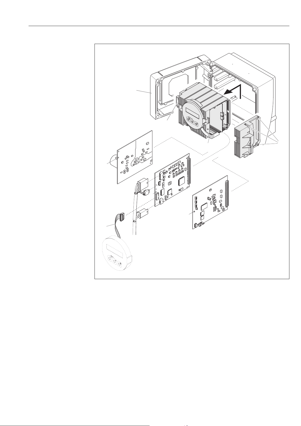
Proline Promass 80 PROFIBUS PA Troubleshooting
6
7
8
5
5
5
3
4
7.1
7.3
7.2
1
2
3
Fig. 37: Field housing: removing and installing printed circuit boards
1 Housing cover
2 Electronics module
3 Ribbon cable (display module)
4 Screws of electronics compartment cover
5 Aperture for installing/removing boards
6 Power unit board
7 Amplifier board
7.1 Signal cable (sensor)
7.2 Excitation current cable (sensor)
7.3 S-DAT (sensor data storage device)
8I/O board
a0004770
Endress+Hauser 83
Page 84
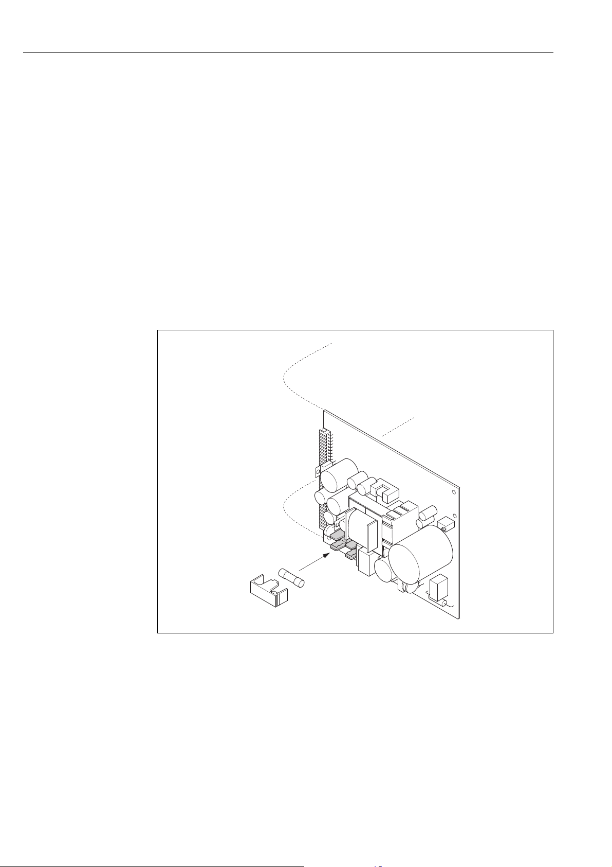
Troubleshooting Proline Promass 80 PROFIBUS PA
1
2
9.5.2 Replacing the device fuse
#
"
Warning!
Risk of electric shock. Exposed components carry dangerous voltages. Make sure that the power
supply is switched off before you remove the cover of the electronics compartment.
The main fuse is on the power unit board å 36
The procedure for replacing the fuse is as follows:
1. Switch off power supply.
2. Remove the power unit board ä 80
3. Remove the protection cap (1) and replace the device fuse (2).
Only use the following fuse type:
– 20 to 55 V AC / 16 to 62 V DC 2.0 A slow-blow / 250 V; 5.2 × 20 mm
– Power supply 85 to 260 V AC 0.8 A slow-blow / 250 V; 5.2 × 20 mm
– Ex-rated devices see the Ex documentation
4. Installation is the reverse of the removal procedure.
Caution!
Use only original Endress+Hauser parts.
a0001148
Fig. 38: Replacing the device fuse on the power unit board
1 Protective cap
2 Device fuse
84 Endress+Hauser
Page 85
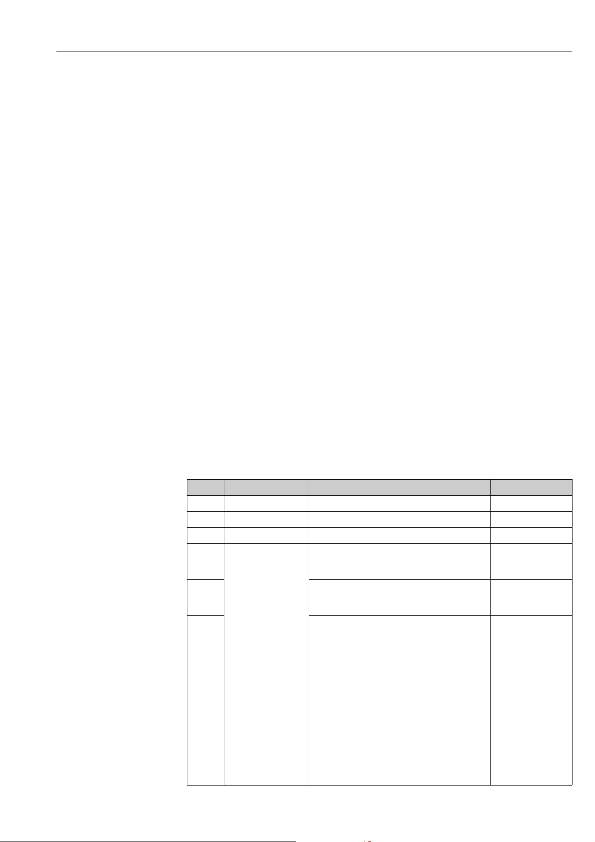
Proline Promass 80 PROFIBUS PA Troubleshooting
9.6 Return
Caution!
"
Do not return a measuring device if you are not absolutely certain that all traces of hazardous
substances have been removed, e.g. substances which have penetrated crevices or diffused through
plastic.
Costs incurred for waste disposal and injury (burns, etc.) due to inadequate cleaning will be charged
to the owner-operator.
The following steps must be taken before returning a flow measuring device to Endress+Hauser,
e.g. for repair or calibration:
• Always enclose a duly completed "Declaration of contamination" form. Only then can
Endress+Hauser transport, examine and repair a returned device.
• Enclose special handling instructions if necessary, for example a safety data sheet as per
EC REACH Regulation No. 1907/2006.
• Remove all residues. Pay special attention to the grooves for seals and crevices which could
contain residues. This is particularly important if the substance is hazardous to health, e.g.
flammable, toxic, caustic, carcinogenic, etc.
!
!
Note!
You will find a preprinted "Declaration of contamination" form at the back of these Operating
Instructions.
9.7 Disposal
Observe the regulations applicable in your country!
9.8 Software history
Note!
Uploading/downloading between different software versions is normally only possible with special
service software.
Date Software version Changes to software Documentation
10.2012 3.06.XX – 71197488/13.12
06.2010 3.06.XX Software adjustment 71116470/06.10
12.2007 3.05.XX Introduction of a new PROFIBUS PA I/O board 71066150/12.07
12.2006 2.03.XX New Sensor:
–Promass S
–Promass P
12.2005 Software expansion:
– Promass I DN80, DN50FB
– General device functions
11.2004 Software expansion:
– New sensor DN 250
New functionalities:
– Empty pipe detection via excitation current
(EPD EXC.CURR. (6426))
– DEVICE SOFTWARE (8100) Device software
displayed (NAMUR recommendation 53)
71036013/12.06
71008415/12.05
50100101/11.04
Endress+Hauser 85
Page 86
Troubleshooting Proline Promass 80 PROFIBUS PA
Date Software version Changes to software Documentation
10.2003 Amplifier:
1.06.XX
Communication module:
2.03.XX
12.2002 Amplifier:
2.02.00
04.2002 Amplifier:
1.02.01
03.2002 Communication module:
2.00.01
11.2001 Amplifier:
1.02.01
07.2001 Amplifier:
1.02.00
Communication module:
1.01.00
Software expansion:
– Language groups
– Corrected volume measurement
– Adjustments to Fieldcheck and Simubox
– New error messages
– SIL2 support
– The totalizer values are also updated without
integration in cyclic data exchange
– Support for corrected volume flow and standard
density process variables
New functionalities:
– Operation hours counter
– Intensity of background illumination adjustable
– Pulse output simulation
– Counter for access code
– Upload/download via ToF Tool - Fieldtool package
Compatible with service protocol:
– ToF Tool - Fieldtool Package
(the latest SW version can be downloaded under:
www.tof-fieldtool.endress.com)
PROFIBUS operation via:
– Commuwin II version 2.08-1 (update C) and higher
Software expansion:
Extended functions of Promass E
Software adjustment: 50100101/04.02
Software expansion:
– New error messages:
061, 121, 501
– Extension of control systems in cyclic data exchange
Control variables (measuring mode):
–0 8: Unidirectional
–0 9: Bidirectional
– Communication software update possible via service
protocol
Software adjustment
Original software
Compatible with:
– Fieldtool
– Commuwin II (version 2.07.02 and higher)
– PROFIBUS DP/PA Profile Version 3.0
50100101/10.03
50100101/09.02
50100101/06.01
86 Endress+Hauser
Page 87
Proline Promass 80 PROFIBUS PA Technical data
10 Technical data
10.1 Technical data at a glance
10.1.1 Applications
ä 5
10.1.2 Function and system design
Measuring principle Mass flow measurement by the Coriolis principle
Measuring system ä 7
10.1.3 Input
Measured variable • Mass flow (proportional to the phase difference between two sensors mounted on the measuring
tube to register a phase shift in the oscillation)
• Fluid density (proportional to resonance frequency of the measuring tube)
• Fluid temperature (measured with temperature sensors)
Measuring range Measuring ranges for liquids (Promass F):
DN Range for full scale values (liquids)
[mm] [inch]
8 3/8" 0 to 2 000 kg/h 0 to 73.5 lb/min
15 1/2" 0 to 6 500 kg/h 0 to 238 lb/min
25 1" 0 to 18 000 kg/h 0 to 660 lb/min
40 1 ½" 0 to 45 000 kg/h 0 to 1 650 lb/min
50 2" 0 to 70 000 kg/h 0 to 2 570 lb/min
80 3" 0 to 180 000 kg/h 0 to 6 600 lb/min
100* 4" * 0 to 350 000 kg/h 0 to 12 860 lb/min
150* 6" * 0 to 800 000 kg/h 0 to 29 400 lb/min
250* 10" * 0 to 2 200 000 kg/h 0 to 80 860 lb/min
* only Promass F
Measuring ranges for liquids (Promass E, H, S, P):
DN Range for full scale values (liquids)
[mm] [inch]
8 3/8" 0 to 2 000 kg/h 0 to 73.5 lb/min
15 1/2" 0 to 6 500 kg/h 0 to 238 lb/min
25 1" 0 to 18 000 kg/h 0 to 660 lb/min
40 1 ½" 0 to 45 000 kg/h 0 to 1 650 lb/min
50 2" 0 to 70 000 kg/h 0 to 2 570 lb/min
80* 3" * 0 to 180 000 kg/h 0 to 6600 lb/min
* only Promass E
g
g
min(F)
min(F)
to
to
g
g
max(F)
max(F)
Endress+Hauser 87
Page 88
Technical data Proline Promass 80 PROFIBUS PA
Measuring ranges for liquids (Promass A):
DN Range for full scale values (liquids)
[mm] [inch]
1 1/24" 0 to 20 kg/h 0 to 0.7 lb/min
2 1/12" 0 to 100 kg/h 0 to 3.7 lb/min
4 1/8" 0 to 450 kg/h 0 to 16.5 lb/min
g
min(F)
Measuring ranges for liquids (Promass I):
DN Range for full scale values (liquids)
[mm] [inch]
8 3/8" 0 to 2 000 kg/h 0 to 73.5 lb/min
15 1/2" 0 to 6 500 kg/h 0 to 238 lb/min
15 FB 1/2" FB 0 to 18 000 kg/h 0 to 660 lb/min
25 1" 0 to 18 000 kg/h 0 to 660 lb/min
25 FB 1" FB 0 to 45 000 kg/h 0 to 1 650 lb/min
40 1 ½" 0 to 45 000 kg/h 0 to 1 650 lb/min
40 FB 1 ½" FB 0 to 70 000 kg/h 0 to 2 570 lb/min
50 2" 0 to 70 000 kg/h 0 to 2 570 lb/min
50 FB 2" FB 0 to 180 000 kg/h 0 to 6 600 lb/min
80 3" 0 to 180 000 kg/h 0 to 6 600 lb/min
FB = Full bore versions of Promass I
g
min(F)
to
to
g
g
max(F)
max(F)
Measuring ranges for gases, generell, (except Promass H)
The full scale values depend on the density of the gas. Use the formula below to calculate the full
scale values:
=
g
max(G)
= Max. full scale value for gas [kg/h (lb/min)]
g
max(G)
= Max. full scale value for liquid [kg/h (lb/min)]
g
max(F)
= Gas density in [kg/m (lb/ft)] for process conditions
(G)
Here,
g
max(G)
g
max(F)
: x [kg/m (lb/ft)]
(G)
can never be greater than
g
max(F)
Measuring ranges for gases (Promass F):
DN x
[mm] [inch]
83/8" 60
15 ½" 80
25 1" 90
40 1½" 90
50 2" 90
80 3" 110
100 4" 130
150 6" 200
250 10" 200
88 Endress+Hauser
Page 89
Proline Promass 80 PROFIBUS PA Technical data
Measuring ranges for gases (Promass E)
DN x
[mm] [inch]
83/8" 85
15 ½" 110
25 1" 125
40 1½" 125
50 2" 125
80 3" 155
Measuring ranges for gases (Promass P, S)
DN x
[mm] [inch]
83/8" 60
15 ½" 80
25 1" 90
40 1½" 90
50 2" 90
Measuring ranges for gases (Promass A)
DN x
[mm] [inch]
1 1/24" 32
2 1/12" 32
41/8" 32
Measuring ranges for gases (Promass I)
DN x
[mm] [inch]
83/8" 60
15 1/2" 80
15 FB 1/2" FB 90
25 1" 90
25 FB 1" FB 90
40 1 ½" 90
40 FB 1 ½" FB 90
50 2" 90
50 FB 2" FB 110
80 3" 110
FB = Full bore versions of Promass I
Endress+Hauser 89
Page 90

Technical data Proline Promass 80 PROFIBUS PA
Calculation example for gas:
• Sensor type: Promass F, DN 50
• Gas: air with a density of 60.3 kg/m³ (at 20 °C and 50 bar)
• Measuring range (liquid): 70 000 kg/h
• x = 90 (for Promass F DN 50)
Max. possible full scale value:
g
max(G)
=
g
max(F)
·
÷ x [kg/m³] = 70 000 kg/h · 60.3 kg/m³ ÷ 90 kg/m³ = 46 900 kg/h
(G)
Recommended full scale values
See information ä 110 ("Limiting flow")
Operable flow range Greater than 1 000 : 1. Flows above the preset full scale value do not overload the amplifier, i.e.
totalizer values are registered correctly.
Input signal Status input (auxiliary input):
U = 3 to 30 V DC, R
= 5 k, galvanically isolated.
i
Configurable for: positive zero return, error message reset, zero point adjustment start, batching
start/stop (optional), totalizer reset for batching (optional).
10.1.4 Output
Output signal PROFIBUS PA interface:
• PROFIBUS PA in accordance with EN 50170 Volume 2, IEC 61158-2 (MBP),
galvanically isolated
• Profile Version 3.0
• Current consumption: 11 mA
• Permitted supply voltage: 9 to 32 V
• Bus connection with integrated reverse polarity protection
• Error current FDE (Fault Disconnection Electronic): 0 mA
• Data transmission rate: 31.25 kBit/s
• Signal coding: Manchester II
• Function blocks: 4 × Analog Input, 2 × Totalizer
• Output data: Mass flow, Volume flow, Density, Temperature, Totalizer
• Input data: Positive zero return (ON/OFF), Zero point adjustment, Measuring mode, Totalizer
control
• Bus address can be configured via miniature switches, via the local display (optional) or operating
program
Signal on alarm PROFIBUS PA interface:
Status and alarm messages in accordance with PROFIBUS Profile Version 3.0
90 Endress+Hauser
Page 91

Proline Promass 80 PROFIBUS PA Technical data
10.1.5 Power supply
Electrical connections ä 25
Supply voltage 85 to 260 V AC, 45 to 65 Hz
20 to 55 V AC, 45 to 65 Hz
16 to 62 V DC
Cable entries Power supply and signal cables (inputs/outputs):
• Cable entry M20 × 1.5 (8 to 12 mm / 0.31 to 0.47 inch)
• Threads for cable entries, ½" NPT, G ½"
Connecting cable for remote version:
• Cable entry M20 × 1.5 (8 to 12 mm / 0.31 to 0.47 inch)
• Threads for cable entries, ½" NPT, G ½"
Cable specifications,
remote version
Power consumption AC: <15 VA (including sensor)
Power supply failure Lasting min. 1 power cycle:
Potential equalization No measures necessary.
ä 28
DC: <15 W (including sensor)
Switch-on current:
• max. 13.5 A (< 50 ms) at 24 V DC
• max. 3 A (< 5 ms) at 260 V AC
• EEPROM saves measuring system data if power supply fails
• HistoROM/S-DAT: exchangeable data storage chip which stores the data of the sensor (nominal
diameter, serial number, calibration factor, zero point, etc.)
Endress+Hauser 91
Page 92
Technical data Proline Promass 80 PROFIBUS PA
0
±0.5
±0.1
[%]
0 50 100
kg/h
±0.2
±0.3
±0.4
105 20 30 40 60 70 80 90
10.1.6 Performance characteristics
Reference operating conditions
Performance characteristic
ass A
Prom
• Error limits following ISO/DIN 11631
• Water, typically +20 to +30 °C (+68 to +86 °F); 2 to 4 bar (30 to 60 psi)
• Data according to calibration protocol ±5 °C (±9 °F) and ±2 bar (±30 psi)
• Accuracy based on accredited calibration rigs according to ISO 17025
Maximum measured error
The following values refer to the pulse/frequency output.
The additional measured error at the
current output is typically ±5 μA.
Design fundamentals ä 93.
o.r. = of reading; 1 g/cc = 1 kg/l; T = medium temperature
• Mass flow and volume flow (liquids): ±0.10% o.r.
M
ass flow (gases): ±0.50% o.r.
•
• Density (liquids)
±0.0005 g/cc (under reference conditions)
±0.0005 g/cc (after field density calibration under process conditions)
±0.002 g/cc (after special density calibration)
±0.02 g/cc (over the entire measuring range of the sensor)
• Special density calibration (optional):
– Calibration range: 0.0 to 1.8 g/cc, +5 to +80 °C (+41 to +176 °F)
– Operation range: 0.0 to 5.0 g/cc, –50 to +200 °C (–58 to +392 °F)
• Temperature: ±0.5 °C ± 0.005 · T °C; (±1 °F ± 0.003 · (T - 32) °F)
Zero point stability
DN Max. full scale value Zero point stability
[mm] [inch] [kg/h] or [l/h] [lb/min] [kg/h] or [l/h] [lb/min]
1 1/24" 20 0.73 0.0010 0.000036
2 1/12" 100 3.70 0.0050 0.00018
4 1/8" 450 16.5 0.0225 0.0008
Example for max. measured error
a0003401
Fig. 39: Max. measured error in % o.r. (example: Promass A, DN 2)
92 Endress+Hauser
Page 93
Proline Promass 80 PROFIBUS PA Technical data
Flow values (example)
Turn down Flow Max. measured error
[kg/h] [lb/min.] [% o.r.]
250:1 0.4 0.0147 1.250
100:1 1.0 0.0368 0.500
25:1 4,0 0.1470 0.125
10:1 10 0.3675 0.100
2:1 50 1.8375 0.100
o.r. = of reading; Design fundamentals ä 93
Repeatability
Design fundamentals ä 93
o.r. = of reading; 1 g/cc = 1 kg/l; T = medium temperature
• Mass flow and volume flow (liquids): ±0.05% o.r.
Mass flow (gases): ±0.25% o.r.
•
• Density (liquids): ±0.00025 g/cc
• Temperature: ±0.25 °C ± 0.0025 · T °C; (±0.5 °F ± 0.0015 · (T–32) °F)
Influence of medium temperature
When there is a difference between the temperature for zero point
adjustment and the process
temperature, the typical measured error of the sensor is ±0.0002% of the full scale value / °C
(±0.0001% of the full scale value/°F).
Influence of medium pressure
A difference in pressure between the calibration
pressure and the process pressure does not have
any effect on the accuracy.
Design fundamentals
Dependent on the flow:
•Flow
Zero point stability ÷ (Base accuracy ÷ 100)
– Max. measured error: ±Base accuracy in % o.r.
– Repeatability: ± ½ · Base accuracy in % o.r.
• Flow < Zero point stability ÷ (Base accuracy ÷ 100)
– Max. measured error: ± (Zero point stability ÷ measured value) · 100% o.r.
– Repeatability: ± ½ · (Zero point stability ÷ measured value) · 100% o.r.
o.r. = of reading
Base accuracy for
Mass flow liquids 0.10
Volume flow liquids 0.10
Mass flow gases 0.50
Endress+Hauser 93
Page 94
Technical data Proline Promass 80 PROFIBUS PA
0
±0.5
±0.2
±1.0
[%]
012 4 6 8 10 12 14 16 18 t/h
Performance characteristic Promass E
Maximum measured error
The following values refer to the pulse/frequency output.
The additional measured error at the
current output is typically ±5 μA.
Design fundamentals ä 96.
o.r. = of reading; 1 g/cc = 1 kg/l; T = medium temperature
• Mass flow and volume flow (liquids): ±0.25% o.r.
M
ass flow (gases): ±0.75% o.r.
•
• Density (liquids)
±0.0005 g/cc (under reference conditions)
±0.0005 g/cc (after field density calibration under process conditions)
±0.02 g/cc (over the entire measuring range of the sensor)
• Temperature: ±0.5 °C ± 0.005 · T °C; (±1 °F ± 0.003 · (T - 32) °F)
Zero point stability
DN Zero point stability
[mm] [inch] [kg/h] or [l/h] [lb/min]
8 3/8" 0.20 0.0074
15 ½" 0.65 0.0239
25 1" 1.80 0.0662
40 1½" 4,50 0.1654
50 2" 7.00 0.2573
80 3" 18.00 0.6615
Example for max. measured error
a0004611
Fig. 40: Max. measured error in % o.r. (example: Promass E, DN 25)
94 Endress+Hauser
Page 95
Proline Promass 80 PROFIBUS PA Technical data
Flow values (example)
Turn down Flow Maximum measured error
[kg/h] or [l/h] [lb/min] [% o.r.]
250 : 1 72 2.646 2.50
100 : 1 180 6.615 1.00
25 : 1 720 26.46 0.25
10 : 1 1800 66.15 0.25
2 : 1 9000 330.75 0.25
o.r. = of reading; Design fundamentals ä 96
Repeatability
Design fundamentals ä 96
o.r. = of reading; 1 g/cc = 1 kg/l; T = medium temperature
• Mass flow and volume flow (liquids): ±0.10% o.r.
Mass flow (gases): ±0.35% o.r.
•
• Density (liquids): ±0.00025 g/cc
• Temperature: ±0.25 °C ± 0.0025 · T °C; (±0.5 °F ± 0.0015 · (T–32) °F)
Influence of medium temperature
When there is a difference between the temperature for zero point
adjustment and the process
temperature, the typical measured error of the sensor is ±0.0002% of the full scale value / °C
(±0.0001% of the full scale value/°F).
Influence of medium pressure
The table below shows the effect on accuracy of mass flow due
to a difference between calibration
pressure and process pressure.
DN
[mm] [inch] [% o.r./bar]
8 3/8" no influence
15 ½" no influence
25 1" no influence
40 1½" no influence
50 2" –0.009
80 3" –0.020
o.r. = of reading
Endress+Hauser 95
Page 96
Technical data Proline Promass 80 PROFIBUS PA
Design fundamentals
Dependent on the flow:
•Flow
Zero point stability ÷ (Base accuracy ÷ 100)
– Max. measured error: ±Base accuracy in % o.r.
– Repeatability: ± ½ · Base accuracy in % o.r.
• Flow < Zero point stability ÷ (Base accuracy ÷ 100)
– Max. measured error: ± (Zero point stability ÷ measured value) · 100% o.r.
– Repeatability: ± ½ · (Zero point stability ÷ measured value) · 100% o.r.
o.r. = of reading
Base accuracy for
Mass flow liquids 0.25
Volume flow liquids 0.25
Mass flow gases 0.75
Performance characteristic
omass F
Pr
Maximum measured error
The following values refer to the pulse/frequency output.
The additional measured error at the
current output is typically ±5 μA.
Design fundamentals ä 98.
o.r. = of reading; 1 g/cc = 1 kg/l; T = medium temperature
• Mass flow and volume flow (liquids):
.05% o.r. (PremiumCal, für Massedurchfluss)
±0
±0.10% o.r.
• Mass flow (gases): ±0.35% o.r.
• Density (liquids)
±0.0005 g/cc (under reference conditions)
±0.0005 g/cc (after field density calibration under process conditions)
±0.001 g/cc (after special density calibration)
±0.01 g/cc (over the entire measuring range of the sensor)
• Special density calibration (optional):
– Calibration range: 0.0 to 1.8 g/cc, +5 to +80 °C (+41 to +176 °F)
– Operation range: 0.0 to 5.0 g/cc, –50 to +200 °C (–58 to +392 °F)
• Temperature: ±0.5 °C ± 0.005 · T °C; (±1 °F ± 0.003 · (T - 32) °F)
Zero point stability Promass F (standard)
DN Zero point stability Promass F (Standard)
[mm] [inch] [kg/h] or [l/h] [lb/min]
8 3/8" 0.030 0.001
15 ½" 0.200 0.007
25 1" 0.540 0.019
40 1½" 2.25 0.083
50 2" 3.50 0.129
80 3" 9.00 0.330
100 4" 14,00 0.514
150 6" 32.00 1.17
250 10" 88.00 3.23
96 Endress+Hauser
Page 97
Proline Promass 80 PROFIBUS PA Technical data
0
±0.5
±0.2
±1.0
[%]
024 6 8 10 12 14 16 18 t/h
Zero point stability Promass F (high-temperature version)
DN Zero point stability Promass F (high-temperature version)
[mm] [inch] [kg/h] or [l/h] [lb/min]
25 1" 1.80 0.0661
50 2" 7.00 0.2572
80 3" 18.0 0.6610
Example for max. measured error
a0004604
Fig. 41: Max. measured error in % o.r. (example: Promass F, DN 25)
Flow values (example)
Turn down Flow Maximum measured error
[kg/h] or [l/h] [lb/min] [% o.r.]
500 : 1 36 1.323 1.5
100 : 1 180 6.615 0.3
25 : 1 720 26.46 0.1
10 : 1 1800 66.15 0.1
2 : 1 9000 330.75 0.1
o.r. = of reading; Design fundamentals ä 98
Repeatability
Design fundamentals ä 98.
o.r. = of reading; 1 g/cc = 1 kg/l; T = medium temperature
• Mass flow and volume flow (liquids):
±0.025% o.r. (PremiumCal, for mass flow)
±0.05% o.r.
• Mass flow (gases): ±0.25% o.r.
• Density (liquids): ±0.00025 g/cc
• Temperature: ±0.25 °C ± 0.0025 · T °C; (±0.5 °F ± 0.0015 · (T–32) °F)
Endress+Hauser 97
Page 98
Technical data Proline Promass 80 PROFIBUS PA
Influence of medium temperature
When there is a difference between the temperature fo
r zero point adjustment and the process
temperature, the typical measured error of the sensor is ±0.0002% of the full scale value / °C
(±0.0001% of the full scale value/°F).
Influence of medium pressure
The table below shows the effect on
accuracy of mass flow due to a difference between calibration
pressure and process pressure.
DN Promass F (standard) Promass F (high-temperature version)
[mm] [inch] [% o.r./bar] [% o.r./bar]
8 3/8" no influence –
15 ½" no influence –
25 1" no influence no influence
40 1½" –0.003 –
50 2" –0.008 –0.008
80 3" –0.009 –0.009
100 4" –0.007 –
150 6" –0.009 –
250 10" –0.009 –
o.r. = of reading
Design fundamentals
Dependent on the flow:
•Flow
Zero point stability ÷ (Base accuracy ÷ 100)
– Max. measured error: ±Base accuracy in % o.r.
– Repeatability: ± ½ · Base accuracy in % o.r.
• Flow < Zero point stability ÷ (Base accuracy ÷ 100)
– Max. measured error: ± (Zero point stability ÷ measured value) · 100% o.r.
– Repeatability: ± ½ · (Zero point stability ÷ measured value) · 100% o.r.
o.r. = of reading
Base accuracy for
Mass flow liquids, PremiumCal 0.05
Mass flow liquids 0.10
Volume flow liquids 0.10
Mass flow gases 0.35
98 Endress+Hauser
Page 99
Proline Promass 80 PROFIBUS PA Technical data
Performance characteristic Promass H
Maximum measured error
The following values refer to the pulse/frequency output.
The additional measured error at the
current output is typically ±5 μA.
Design fundamentals ä 101.
o.r. = of reading; 1 g/cc = 1 kg/l; T = medium temperature
Material measuring tube: Zirconium 702/R 60702
• Mass flow and volume flow (liquids): ±0.15% o.r.
Density (liquids)
•
±0.0005 g/cc (under reference conditions)
±0.0005 g/cc (after field density calibration under process conditions)
±0.002 g/cc (after special density calibration)
±0.02 g/cc (over the entire measuring range of the sensor)
Special density calibration (optional):
– Calibration range: 0.0 to 1.8 g/cc, +10 to +80 °C (+50 to +176 °F)
– Operation range: 0.0 to 5.0 g/cc, –50 to +200 °C (–58 to +392 °F)
• Temperature: ±0.5 °C ± 0.005 · T °C; (±1 °F ± 0.003 · (T - 32) °F)
Material measuring tube: Tantalum 2.5W
• Mass flow and volume flow (liquids): ±0.15% o.r.
Mass flow (gases): ±0.50% o.r.
•
• Density (liquids)
±0.0005 g/cc (under reference conditions)
±0.0005 g/cc (after field density calibration under process conditions)
±0.002 g/cc (after special density calibration)
±0.02 g/cc (over the entire measuring range of the sensor)
Special density calibration (optional)
– Calibration range: 0.0 to 1.8 g/cc, +10 to +80 °C (+50 to +176 °F)
– Operation range: 0.0 to 5.0 g/cc, –50 to +150 °C (–58 to +302 °F)
• Temperature: ±0.5 °C ± 0.005 · T °C; (±1 °F ± 0.003 · (T - 32) °F)
Zero point stability
DN Zero point stability
[mm] [inch] [kg/h] or [l/h] [lb/min]
8 3/8" 0.20 0.007
15 ½" 0.65 0.024
25 1" 1.80 0.066
40 1½" 4,50 0.165
50 2" 7.00 0.257
Endress+Hauser 99
Page 100
Technical data Proline Promass 80 PROFIBUS PA
0
±0.5
±0.2
±1.0
[%]
012 4 6 8 10 12 14 16 18 t/h
Example for max. measured error
a0004611
Fig. 42: Max. measured error in % o.r. (example: Promass H, DN 25)
Flow values (example)
Turn down Flow Maximum measured error
[kg/h] or [l/h] [lb/min] [% o.r.]
250 : 1 72 2.646 2.50
100 : 1 180 6.615 1.00
25 : 1 720 26.46 0.25
10 : 1 1800 66.15 0.10
2 : 1 9000 330.75 0.10
o.r. = of reading; Design fundamentals ä 101
Repeatability
Design fundamentals ä 101.
o.r. = of reading; 1 g/cc = 1 kg/l; T = medium temperature
Material measuring tube: Zirconium 702/R 60702
• Mass flow and volume flow (liquids): ±0.05% o.r.
D
ensity (liquids): ±0.00025 g/cc
•
• Temperature: ±0.25 °C ± 0.0025 · T °C; (±0.5 °F ± 0.0015 · (T–32) °F)
Material measuring tube: Tantalum 2.5W
• Mass flow and volume flow (liquids): ±0.05% o.r.
M
ass flow (gases): ±0.25% o.r.
•
• Density (liquids): ±0.00025 g/cc
• Temperature: ±0.25 °C ± 0.0025 · T °C; (±0.5 °F ± 0.0015 · (T–32) °F)
Influence of medium temperature
When there is a difference between the temperature fo
r zero point
temperature, the typical measured error of the sensor is ±0.0002% of the full scale value / °C
(±0.0001% of the full scale value/°F).
adjustment and the process
100 Endress+Hauser
 Loading...