

Endress+Hauser Proline Promag P 100 Technical Information
TI01102D/06/EN/02.13
71233384
Products Solutions Services
Technical Information
Proline Promag P 100
Electromagnetic flowmeter
The flowmeter for highest medium temperatures with an ultra-compact
transmitter
Application
• The electromagnetic measuring principle is unaffected by
pressure, temperature and flow profile
• Dedicated for chemical and process applications with
corrosive liquids and high medium temperatures
Device properties
• Nominal diameter: max. DN 600 (24")
• All common Ex approvals
• Liner made of PTFE or PFA
• Robust, ultra-compact transmitter housing
• Pre-configured plug connector
Your benefits
• Versatile applications – wide variety of wetted materials
• Energy-saving flow measurement – no pressure loss due to
cross-section constriction
• Maintenance-free – no moving parts
• Space-saving transmitter – full functionality on smallest
footprint
• Time-saving local operation without additional software and
hardware – integrated web server
• Integrated verification – Heartbeat Technology™

Table of contents
Proline Promag P 100
Document information ....................... 3
Symbols used ................................ 3
Function and system design ................... 4
Measuring principle ............................ 4
Measuring system ............................. 5
Device architecture ............................ 5
Safety ..................................... 6
Input ..................................... 6
Measured variable ............................. 6
Measuring range .............................. 6
Operable flow range ........................... 7
Input signal ................................. 7
Output ................................... 8
Output signal ................................ 8
Signal on alarm ............................... 9
Low flow cut off ............................. 10
Galvanic isolation ............................ 11
Protocol-specific data .......................... 11
Power supply ............................. 16
Terminal assignment .......................... 16
Pin assignment, device plug ...................... 20
Supply voltage .............................. 22
Power consumption ........................... 22
Current consumption .......................... 22
Power supply failure .......................... 22
Electrical connection .......................... 23
Potential equalization ......................... 27
Terminals ................................. 29
Cable entries ............................... 29
Cable specification ............................ 29
Process .................................. 36
Medium temperature range ...................... 36
Conductivity ................................ 36
Pressure-temperature ratings .................... 36
Pressure tightness ............................ 39
Flow limit ................................. 40
Pressure loss ............................... 40
System pressure ............................. 40
Vibrations ................................. 40
Mechanical construction .................... 41
Design, dimensions ........................... 41
Weight ................................... 44
Measuring tube specification ..................... 45
Materials .................................. 46
Fitted electrodes ............................. 48
Process connections ........................... 48
Surface roughness ............................ 48
Operability ............................... 48
Operating concept ............................ 48
Remote operation ............................ 48
Certificates and approvals ................... 52
CE mark ................................... 52
C-Tick symbol ............................... 52
Ex approval ................................ 52
Certification PROFIBUS ......................... 53
Modbus RS485 certification ..................... 53
EtherNet/IP certification ........................ 53
Pressure Equipment Directive .................... 53
Other standards and guidelines ................... 53
Ordering information ....................... 54
Performance characteristics .................. 30
Reference operating conditions ................... 30
Maximum measured error ....................... 31
Repeatability ............................... 31
Temperature measurement response time ............ 31
Influence of ambient temperature ................. 31
Installation ............................... 32
Mounting location ............................ 32
Orientation ................................ 33
Inlet and outlet runs .......................... 33
Adapters .................................. 34
Environment .............................. 34
Ambient temperature range ..................... 34
Storage temperature .......................... 35
Degree of protection .......................... 35
Shock resistance ............................. 35
Vibration resistance ........................... 35
Mechanical load ............................. 35
Electromagnetic compatibility (EMC) ............... 35
Application packages ....................... 54
Heartbeat Technology ......................... 54
Accessories ............................... 54
Device-specific accessories ...................... 54
Communication-specific accessories ................ 55
Service-specific accessories ...................... 55
System components ........................... 56
Documentation ............................ 56
Standard documentation ........................ 56
Supplementary device-dependent documentation ....... 56
Registered trademarks ...................... 56
2 Endress+Hauser
Proline Promag P 100
,…,
Document information
Symbols used Electrical symbols
Symbol Meaning
Direct current
A0011197
A terminal to which DC voltage is applied or through which direct current flows.
Alternating current
A0011198
A terminal to which alternating voltage is applied or through which alternating current flows.
Direct current and alternating current
A0017381
• A terminal to which alternating voltage or DC voltage is applied.
• A terminal through which alternating current or direct current flows.
Ground connection
A grounded terminal which, as far as the operator is concerned, is grounded via a grounding
A0011200
system.
Protective ground connection
A terminal which must be connected to ground prior to establishing any other connections.
A0011199
Equipotential connection
A connection that has to be connected to the plant grounding system: This may be a potential
A0011201
equalization line or a star grounding system depending on national or company codes of practice.
Symbols for certain types of information
Symbol Meaning
Allowed
Indicates procedures, processes or actions that are allowed.
A0011182
Preferred
Indicates procedures, processes or actions that are preferred.
A0011183
Forbidden
Indicates procedures, processes or actions that are forbidden.
A0011184
Tip
Indicates additional information.
A0011193
Reference to documentation
Refers to the corresponding device documentation.
A0011194
Reference to page
Refers to the corresponding page number.
A0011195
Reference to graphic
Refers to the corresponding graphic number and page number.
A0011196
Symbols in graphics
Symbol Meaning
1, 2, 3,... Item numbers
Series of steps
A, B, C, ... Views
A-A, B-B, C-C, ... Sections
Flow direction
A0013441
Endress+Hauser 3
Symbol Meaning
-
.
I
L
B
I
U
e
v
Hazardous area
Indicates a hazardous area.
A0011187
Safe area (non-hazardous area)
Indicates a non-hazardous area.
A0011188
Function and system design
Proline Promag P 100
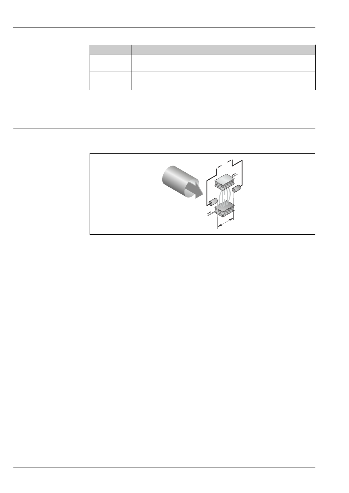
Measuring principle
Following Faraday's law of magnetic induction, a voltage is induced in a conductor moving through a
magnetic field.
A0017035
Ue Induced voltage
B Magnetic induction (magnetic field)
L Electrode spacing
I Current
v Flow velocity
In the electromagnetic measuring principle, the flowing medium is the moving conductor. The
voltage induced (Ue) is proportional to the flow velocity (v) and is supplied to the amplifier by means
of two measuring electrodes. The flow volume (Q) is calculated via the pipe cross-section (A). The DC
magnetic field is created through a switched direct current of alternating polarity.
Formulae for calculation
• Induced voltage Ue = B · L · v
• Volume flow Q = A · v
4 Endress+Hauser
Proline Promag P 100
2 31
5
6
7
4
Measuring system
One device version is available: compact version, transmitter and sensor form a mechanical unit.
Transmitter
Promag 100 Device versions and materials:
Compact, aluminum coated:
Coated aluminum AlSi10Mg
Configuration:
• Via operating tools (e.g. FieldCare)
• Also for device version with 4-20 mA HART, pulse/frequency/switch
A0016693
output:
Via Web browser (e.g. Microsoft Internet Explorer)
• Also for device version with EtherNet/IP output:
– Via Web browser (e.g. Microsoft Internet Explorer)
– Via Add-on Profile Level 3 for automation system from Rockwell
Automation
– Via Electronic Data Sheet (EDS)
Sensor
Promag P Nominal diameter range: DN 15 to 600 (½ to 24")
Materials:
• Sensor housing:
– DN 15 to 300 (½ to 12"): coated aluminum AlSi10Mg
– DN 350 to 600 (14 to 24"): carbon steel with protective varnish
• Measuring tubes
• Liner: PFA, PTFE
• Process connections: 1.0425 (316L)
A0017703
• Electrodes: 1.4435 (316L), Alloy C22, platinum, tantalum, titanium
F316L
2)
• Seals: as per DIN EN 1514-1
• Ground disks: 1.4435 (316L), Alloy C22, tantalum, titanium
1)
: stainless steel 1.4301 (304) or 1.4306 (304L)
, FE 410W B
2)
2)
, HII, S235JRG2, S275JR
, 1.4571 (316L), A105, C22,
1) For flanges made of carbon with Al/Zn protective coating (DN 15 to 300 (½ to 12")) or protective varnish
(DN 350 to 600 (14 to 24"))
2) With Al/Zn protective coating (DN 15 to 300 (½ to 12")) or protective varnish (DN 350 to 600 (14 to 24"))
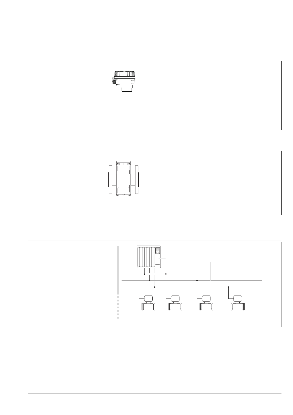
Device architecture
A0021560
1 Possibilities for integrating measuring devices into a system
1 Control system (e.g. PLC)
2 EtherNet/IP
3 PROFIBUS DP
4 Modbus RS485
5 4-20 mA HART, pulse/frequency/switch output
6 Non-hazardous area
7 Non-hazardous area and Zone 2/Div. 2
Endress+Hauser 5

Safety IT security
We only provide a warranty if the device is installed and used as described in the Operating
Instructions. The device is equipped with security mechanisms to protect it against any inadvertent
changes to the device settings.
IT security measures in line with operators' security standards and designed to provide additional
protection for the device and device data transfer must be implemented by the operators themselves.
Endress+Hauser can be contacted to provide support in performing this task.
Input
Measured variable Direct measured variables
• Volume flow (proportional to induced voltage)
• Electrical conductivity
Calculated measured variables
• Mass flow
• Corrected volume flow
• Corrected electrical conductivity
Proline Promag P 100
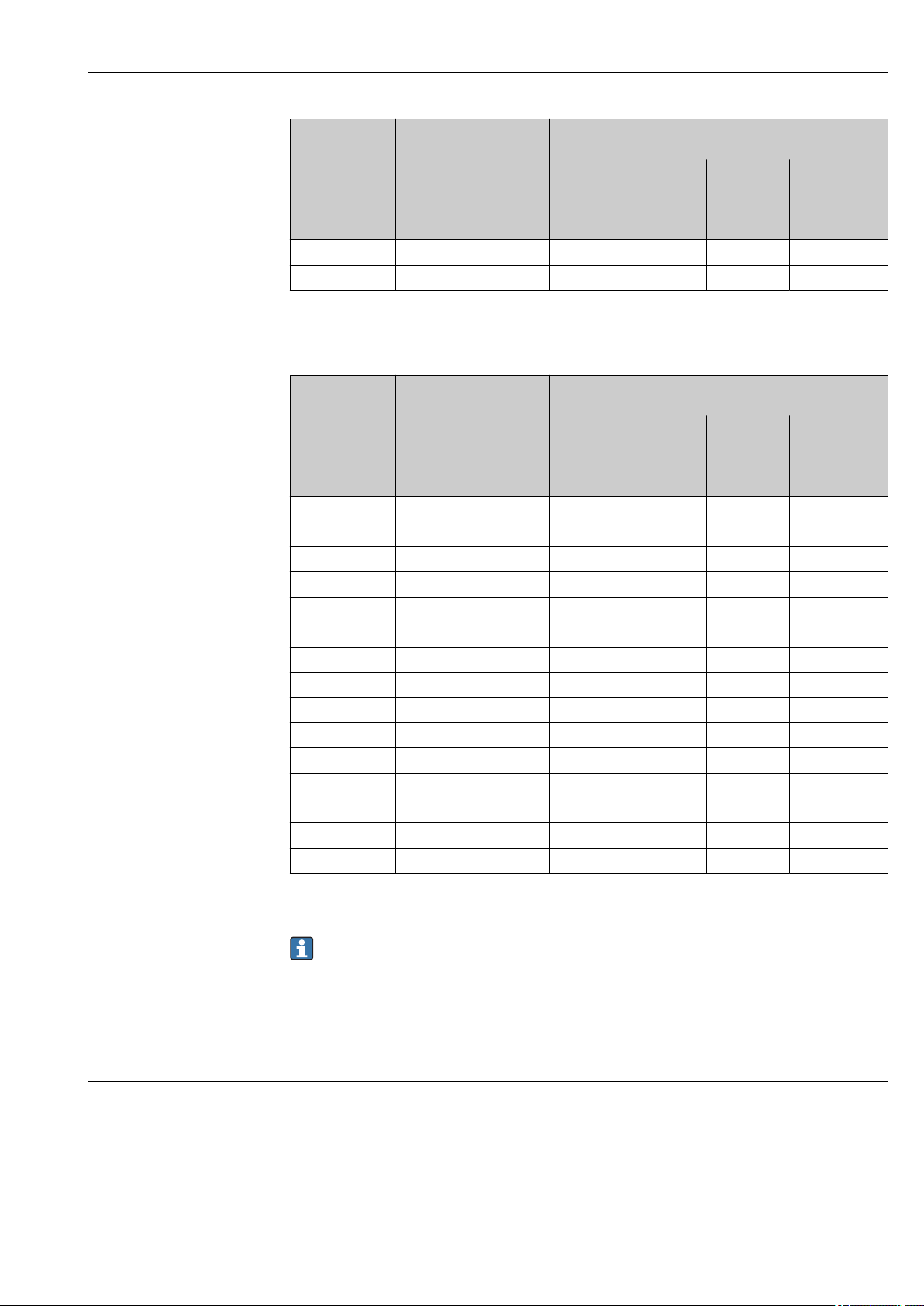
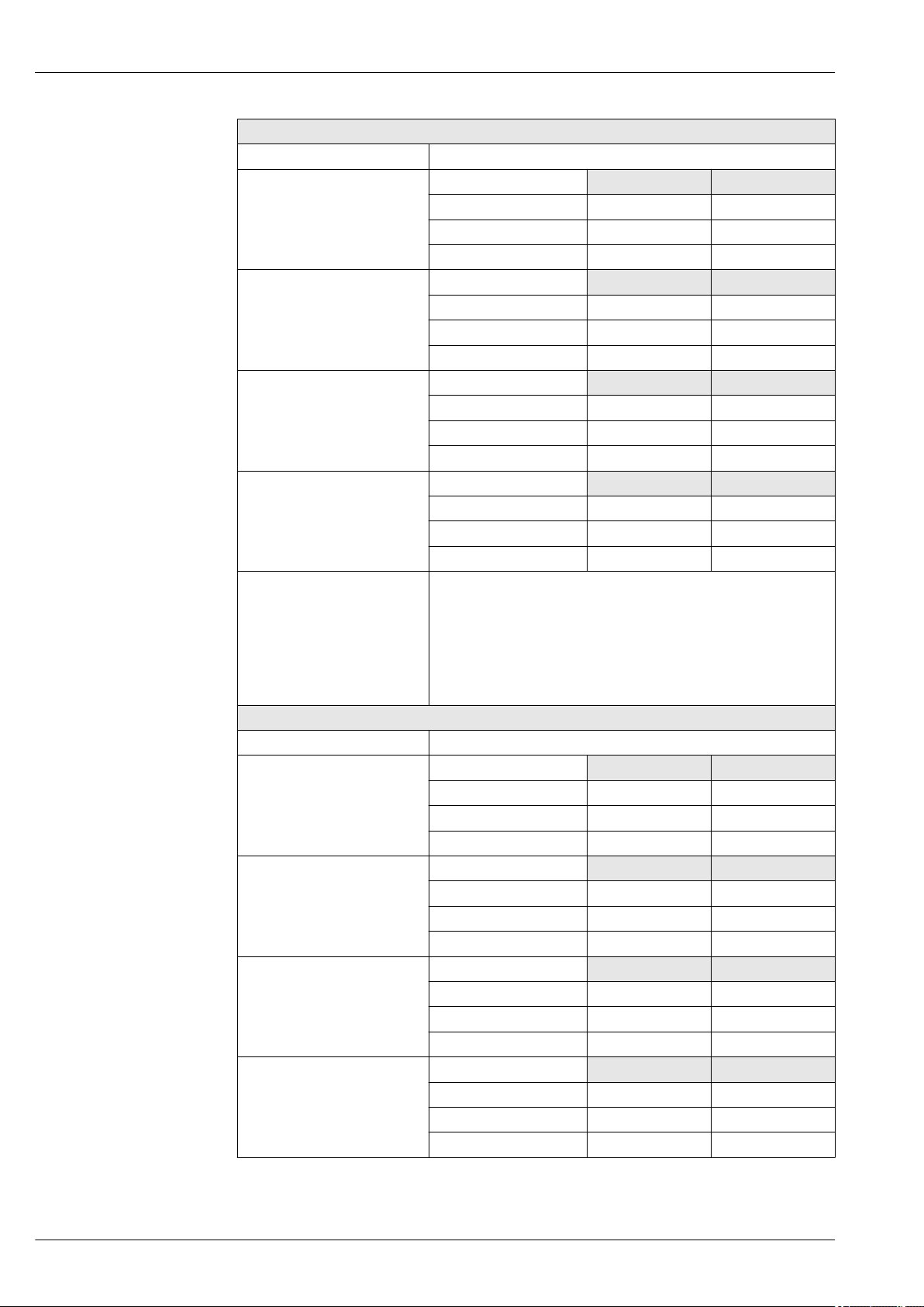
Measuring range
Typically v = 0.01 to 10 m/s (0.03 to 33 ft/s) with the specified accuracy
Electrical conductivity: 5 to 10 000 µS/cm/cm
Flow characteristic values in SI units
Nominal
diameter
[mm] [in] [dm3/min] [dm3/min] [dm3] [dm3/min]
15 ½ 4 to 100 25 0.2 0.5
25 1 9 to 300 75 0.5 1
32 – 15 to 500 125 1 2
40 1 ½ 25 to 700 200 1.5 3
50 2 35 to 1 100 300 2.5 5
65 – 60 to 2 000 500 5 8
80 3 90 to 3 000 750 5 12
100 4 145 to 4 700 1200 10 20
125 – 220 to 7 500 1850 15 30
150 6 20 to 600 m3/h 150 m3/h 0.03 m
200 8 35 to 1 100 m3/h 300 m3/h 0.05 m
250 10 55 to 1 700 m3/h 500 m3/h 0.05 m
300 12 80 to 2 400 m3/h 750 m3/h 0.1 m
350 14 110 to 3 300 m3/h 1 000 m3/h 0.1 m
400 16 140 to 4 200 m3/h 1 200 m3/h 0.15 m
450 18 180 to 5 400 m3/h 1 500 m3/h 0.25 m
Recommended
flow
min./max. full scale value
(v ~ 0.3/10 m/s)
Factory settings
Current output full scale
1)
value
(v ~ 2.5 m/s)
Pulse value
(~ 2 pulse/s)
3
3
3
3
3
3
3
1)
Low flow cut off
(v ~ 0.04 m/s)
2.5 m3/h
5 m3/h
7.5 m3/h
10 m3/h
15 m3/h
20 m3/h
25 m3/h
6 Endress+Hauser
Proline Promag P 100
Nominal
diameter
[mm] [in] [dm3/min] [dm3/min] [dm3] [dm3/min]
500 20 220 to 6 600 m3/h 2 000 m3/h 0.25 m
600 24 310 to 9 600 m3/h 2 500 m3/h 0.3 m
1) HART only
Recommended
flow
min./max. full scale value
(v ~ 0.3/10 m/s)
Factory settings
Current output full scale
1)
value
(v ~ 2.5 m/s)
Pulse value
(~ 2 pulse/s)
3
3
1)
Low flow cut off
(v ~ 0.04 m/s)
30 m3/h
40 m3/h
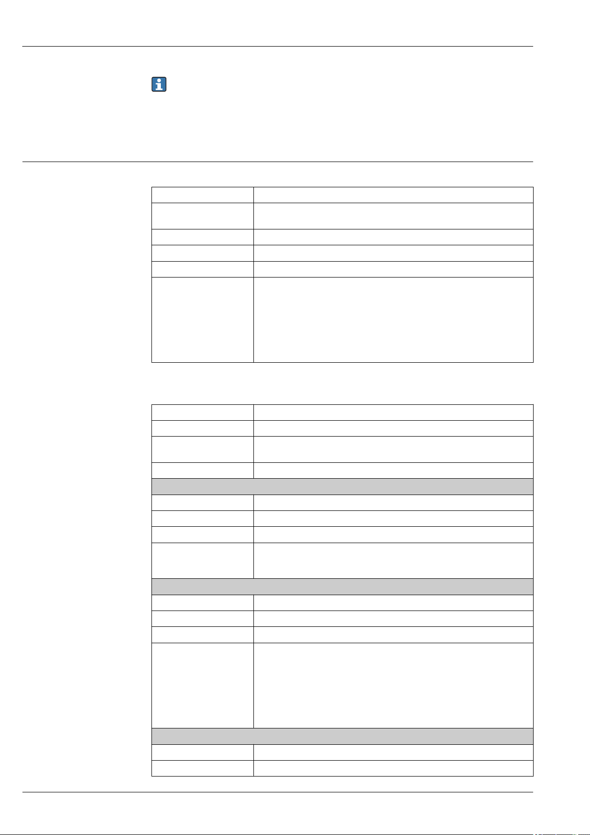
Flow characteristic values in US units
Nominal
diameter
[in] [mm] [gal/min] [gal/min] [gal] [gal/min]
½ 15 1.0 to 27 6 0.1 0.15
1 25 2.5 to 80 18 0.2 0.25
1 ½ 40 7 to 190 50 0.5 0.75
2 50 10 to 300 75 0.5 1.25
3 80 24 to 800 200 2 2.5
4 100 40 to 1 250 300 2 4
6 150 90 to 2 650 600 5 12
8 200 155 to 4 850 1200 10 15
10 250 250 to 7 500 1500 15 30
12 300 350 to 10 600 2400 25 45
14 350 500 to 15 000 3600 30 60
16 400 600 to 19 000 4800 50 60
18 450 800 to 24 000 6000 50 90
20 500 1 000 to 30 000 7500 75 120
24 600 1 400 to 44 000 10500 100 180
Recommended
flow
min./max. full scale value
(v ~ 0.3/10 m/s)
Factory settings
Current output full scale
1)
value
(v ~ 2.5 m/s)
Pulse value
(~ 2 pulse/s)
1)
Low flow cut off
(v ~ 0.04 m/s)
1) HART only
To calculate the measuring range, use the Applicator sizing tool (→ 55)
Recommended measuring range
"Flow limit" section (→ 40)
Operable flow range
Over 1000 : 1
Input signal Fieldbuses
To increase the accuracy of certain measured variables or to calculate the corrected volume flow, the
automation system can continuously write different measured values to the measuring device via
Modbus RS485, EtherNet/IP or HART input:
• Process pressure or fluid temperature to increase accuracy (e.g. external values from Cerabar M,
Cerabar S or iTEMP)
• Reference density for calculating the corrected volume flow
Endress+Hauser 7
Various pressure transmitters and temperature measuring devices can be ordered from Endress
+Hauser: see "Accessories" section (→ 56)
Output
Output signal Current output
Current output 4-20 mA HART (active)
Maximum output values • DC 24 V (when idle)
Load 0 to 700 Ω
Resolution 0.38 µA
Damping Adjustable: 0.07 to 999 s
Assignable measured
variables
Proline Promag P 100
• 22.5 mA
• Volume flow
• Mass flow
• Corrected volume flow
• Flow velocity
• Conductivity
• Corrected conductivity
• Temperature
• Electronics temperature
Pulse/frequency/switch output
Function Can be set to pulse, frequency or switch output
Version Passive, open collector
Maximum input values • DC30 V
• 25 mA
Voltage drop For 25 mA: ≤ DC2 V
Pulse output
Pulse width Adjustable: 0.05 to 2 000 ms
Maximum pulse rate 10 000 Impulse/s
Pulse value Adjustable
Assignable measured
variables
Frequency output
Output frequency Adjustable: 0 to 10 000 Hz
Damping Adjustable: 0 to 999 s
Pulse/pause ratio 1:1
Assignable measured
variables
Switch output
Switching behavior Binary, conductive or non-conductive
Switching delay Adjustable: 0 to 100 s
• Volume flow
• Mass flow
• Corrected volume flow
• Volume flow
• Mass flow
• Corrected volume flow
• Flow velocity
• Conductivity
• Corrected conductivity
• Temperature
• Electronics temperature
8 Endress+Hauser

Proline Promag P 100
Number of switching
cycles
Assignable functions • Off
Unlimited
• On
• Diagnostic behavior
• Limit value:
– Off
– Volume flow
– Mass flow
– Corrected volume flow
– Flow velocity
– Conductivity
– Corrected conductivity
– Totalizer 1-3
– Temperature
– Electronics temperature
• Flow direction monitoring
• Status
– Empty pipe detection
– Low flow cut off
PROFIBUS DP
Signal encoding NRZ code
Data transfer 9.6 kBaud…12 MBaud
Signal on alarm
Modbus RS485
Physical interface In accordance with EIA/TIA-485-A standard
Terminating resistor Integrated, can be activated via DIP switch on the transmitter electronics module
EtherNet/IP
Standards In accordance with IEEE 802.3
Depending on the interface, failure information is displayed as follows:
Current output
4-20 mA
Failure mode Selectable (as per NAMUR recommendation NE 43):
• Minimum value: 3.6 mA
• Maximum value: 22 mA
• Defined value: 3.59 to 22.5 mA
• Actual value
• Last valid value
HART
Device diagnostics Device condition can be read out via HART Command 48
Pulse/frequency/switch output
Pulse output
Failure mode Choose from:
• Actual value
• No pulses
Endress+Hauser 9
Frequency output
Failure mode Choose from:
• Actual value
• Defined value: 0 to 12 500 Hz
• 0 Hz
Switch output
Failure mode Choose from:
• Current status
• Open
• Closed
PROFIBUS DP
Proline Promag P 100
Status and alarm
messages
Diagnostics in accordance with PROFIBUS PA Profile 3.02
Modbus RS485
Failure mode Choose from:
• NaN value instead of current value
• Last valid value
EtherNet/IP
Device diagnostics Device condition can be read out in Input Assembly
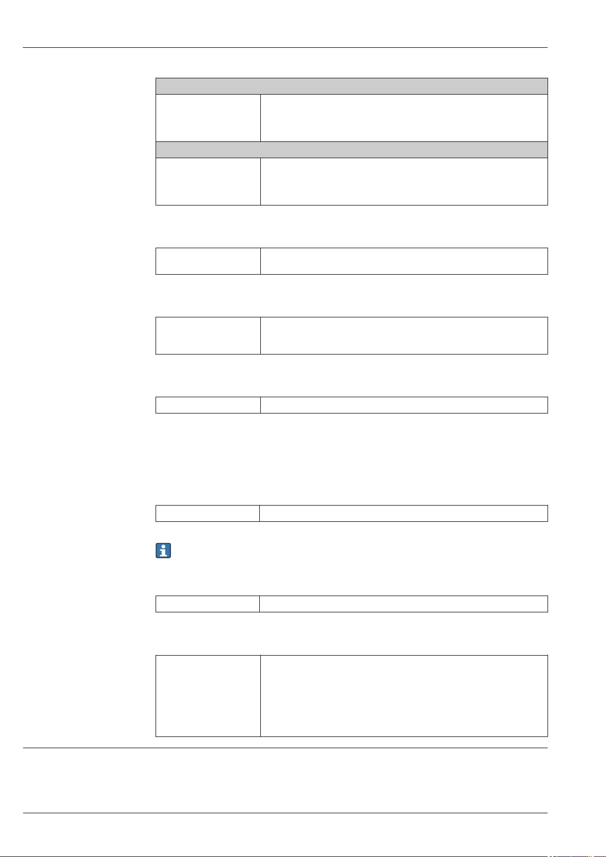
Operating tool
• Via digital communication:
– HART protocol
– PROFIBUS DP
• Via service interface
Plain text display With information on cause and remedial measures
Additional information on remote operation (→ 48)
Web browser
Plain text display With information on cause and remedial measures
Light emitting diodes (LED)
Status information Status indicated by various light emitting diodes
The following information is displayed depending on the device version:
• Supply voltage active
• Data transmission active
• Device alarm/error has occurred
• EtherNet/IP network available
• EtherNet/IP connection established
Low flow cut off
The switch points for low flow cut off are user-selectable.
10 Endress+Hauser

Proline Promag P 100
Galvanic isolation
The following connections are galvanically isolated from each other:
• Outputs
• Power supply
Protocol-specific data HART
Manufacturer ID 0x11
Device type ID 0x3A
HART protocol revision 6.0
Device description files
(DTM, DD)
HART load Min. 250 Ω
Dynamic variables The measured variables can be freely assigned to the dynamic variables.
Information and files under:
www.endress.com
Measured variables for PV (primary dynamic variable)
• Off
• Volume flow
• Mass flow
• Corrected volume flow
• Flow velocity
• Corrected conductivity
• Temperature
• Electronics temperature
Measured variables for SV, TV, QV (secondary, tertiary and quaternary
dynamic variable)
• Volume flow
• Mass flow
• Corrected volume flow
• Flow velocity
• Corrected conductivity
• Temperature
• Electronics temperature
• Totalizer 1
• Totalizer 2
• Totalizer 3
PROFIBUS DP
Manufacturer ID 0x11
Ident number 0x1561
Profile version 3.02
Device description files (GSD,
DTM, DD)
Information and files under:
• www.endress.com
• www.profibus.org
Endress+Hauser 11

Proline Promag P 100
Output values
(from measuring device to
automation system)
Input values
(from automation system to
measuring device)
Supported functions • Identification & Maintenance
Configuration of the device
address
Analog input 1 to 8
• Mass flow
• Volume flow
• Corrected volume flow
• Target mass flow
• Carrier mass flow
• Density
• Reference density
• Concentration
• Dynamic viscosity
• Kinematic viscosity
• Temp. compensated dynamic viscosity
• Temp. compensated kinematic viscosity
• Temperature
• Carrier pipe temperature
• Electronics temperature
• Oscillation frequency
• Oscillation amplitude
• Frequency fluctuation
• Oscillation damping
• Tube damping fluctuation
• Signal asymmetry
• Exciter current
Digital input 1 to 2
• Partially filled pipe detection
• Low flow cut off
Totalizer 1 to 3
• Mass flow
• Volume flow
• Corrected volume flow
Analog output 1 to 3 (fixed assignment)
• Pressure
• Temperature
• Reference density
Digital output 1 to 3 (fixed assignment)
• Digital output 1: switch positive zero return on/off
• Digital output 2: perform zero point adjustment
• Digital output 3: switch switch output on/off
Totalizer 1 to 3
• Totalize
• Reset and hold
• Preset and hold
• Stop
• Operating mode configuration:
– Net flow total
– Forward flow total
– Reverse flow total
Simplest device identification on the part of the control system and
nameplate
• PROFIBUS upload/download
Reading and writing parameters is up to ten times faster with PROFIBUS
upload/download
• Condensed status
Simplest and self-explanatory diagnostic information by categorizing
diagnostic messages that occur
• DIP switches on the I/O electronics module
• Via operating tools (e.g. FieldCare)
Modbus RS485
Protocol Modbus Applications Protocol Specification V1.1
Device type Slave
Slave address range 1 to 247
12 Endress+Hauser
Proline Promag P 100
Broadcast address range 0
Function codes • 03: Read holding register
• 04: Read input register
• 06: Write single registers
• 08: Diagnostics
• 16: Write multiple registers
• 23: Read/write multiple registers
Broadcast messages Supported by the following function codes:
• 06: Write single registers
• 16: Write multiple registers
• 23: Read/write multiple registers
Supported baud rate • 1 200 BAUD
• 2 400 BAUD
• 4 800 BAUD
• 9 600 BAUD
• 19 200 BAUD
• 38 400 BAUD
• 57 600 BAUD
• 115 200 BAUD
Data transfer mode • ASCII
• RTU
Data access Each device parameter can be accessed via Modbus RS485.
For Modbus register information
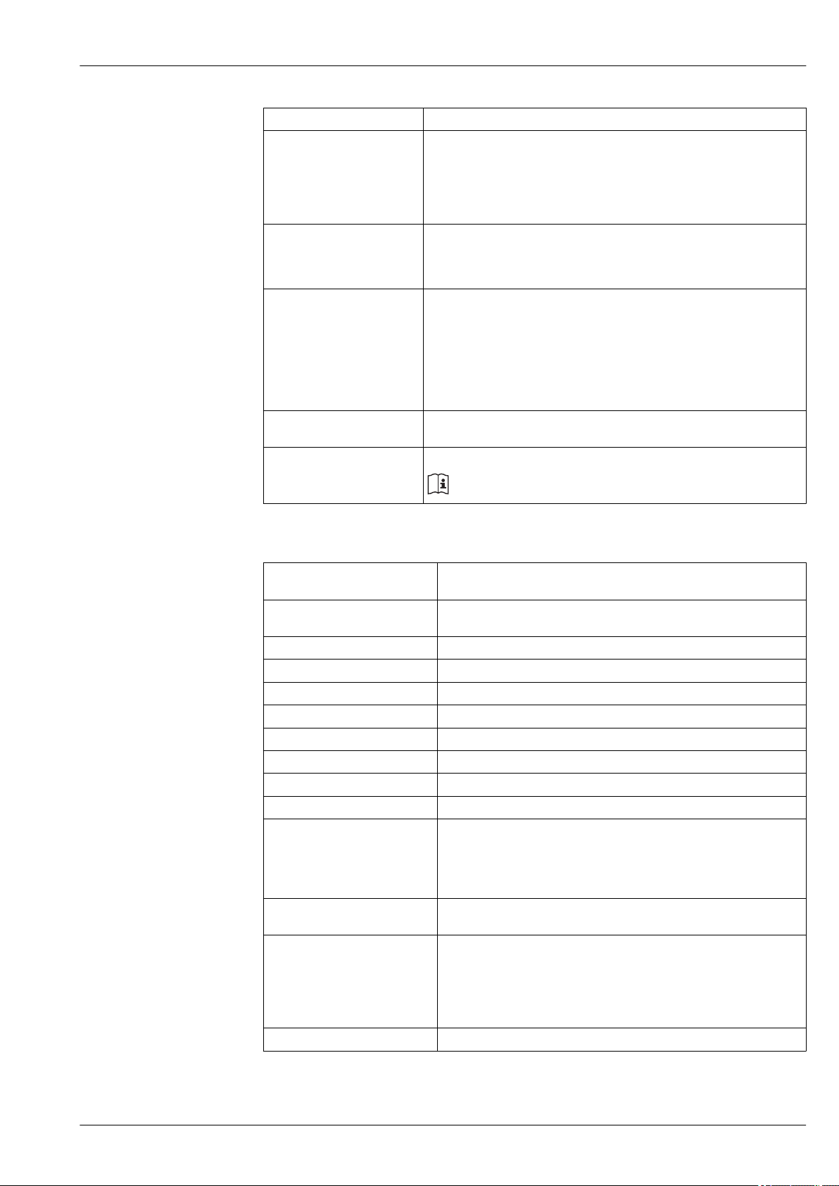
EtherNet/IP
Protocol • The CIP Networks Library Volume 1: Common Industrial Protocol
• The CIP Networks Library Volume 2: EtherNet/IP Adaptation of CIP
Communication type • 10Base-T
• 100Base-TX
Device profile Generic device (product type: 0x2B)
Manufacturer ID 0x49E
Device type ID 0x103A
Baud rates Automatic ¹⁰⁄₁₀₀ Mbit with half-duplex and full-duplex detection
Polarity Auto-polarity for automatic correction of crossed TxD and RxD pairs
Supported CIP connections Max. 3 connections
Explicit connections Max. 6 connections
I/O connections Max. 6 connections (scanner)
Configuration options for
measuring device
Configuration of the EtherNet
interface
Configuration of the device
address
Device Level Ring (DLR) No
• DIP switches on the electronics module for IP addressing
• Manufacturer-specific software (FieldCare)
• Add-on Profile Level 3 for Rockwell Automation control systems
• Web browser
• Electronic Data Sheet (EDS) integrated in the measuring device
• Speed: 10 MBit, 100 MBit, auto (factory setting)
• Duplex: half-duplex, full-duplex, auto (factory setting)
• DIP switches on the electronics module for IP addressing (last octet)
• DHCP
• Manufacturer-specific software (FieldCare)
• Add-on Profile Level 3 for Rockwell Automation control systems
• Web browser
• EtherNet/IP tools, e.g. RSLinx (Rockwell Automation)
Endress+Hauser 13
Proline Promag P 100
Fix Input
RPI 5 ms to 10 s (factory setting: 20 ms)
Exclusive Owner Multicast Instance Size [byte]
Instance configuration: 0x68 398
O → T configuration: 0x66 56
T → O configuration: 0x64 32
Exclusive Owner Multicast Instance Size [byte]
Instance configuration: 0x69 -
O → T configuration: 0x66 56
T → O configuration: 0x64 32
Input only Multicast Instance Size [byte]
Instance configuration: 0x68 398
O → T configuration: 0xC7 -
T → O configuration: 0x64 32
Input only Multicast Instance Size [byte]
Instance configuration: 0x69 -
O → T configuration: 0xC7 -
T → O configuration: 0x65 32
Input Assembly • Current device diagnostics
• Volume flow
• Mass flow
• Corrected volume flow
• Temperature
• Totalizer 1
• Totalizer 2
• Totalizer 3
Configurable Input
RPI 5 ms to 10 s (factory setting: 20 ms)
Exclusive Owner Multicast Instance Size [byte]
Instance configuration: 0x68 398
O → T configuration: 0x66 56
T → O configuration: 0x65 88
Exclusive Owner Multicast Instance Size [byte]
Instance configuration: 0x69 -
O → T configuration: 0x66 56
T → O configuration: 0x64 88
Input only Multicast Instance Size [byte]
Instance configuration: 0x68 398
O → T configuration: 0xC7 -
T → O configuration: 0x64 88
Input only Multicast Instance Size [byte]
Instance configuration: 0x69 -
O → T configuration: 0xC7 -
T → O configuration: 0x65 88
14 Endress+Hauser

Proline Promag P 100
Configurable Input Assembly • Volume flow
• Temperature
• Corrected volume flow
• Mass flow
• Totalizer 1 to 3
• Flow velocity
• Volume flow unit
• Temperature unit
• Corrected volume flow unit
• Mass flow unit
• Unit totalizer 1-3
• Flow velocity unit
Fix Output
Output Assembly • Activation of reset totalizers 1-3
• Activation of reference density compensation
• Activation of temperature compensation
• Reset totalizers 1-3
• External density
• Density unit
• External temperature
• Temperature unit
Configuration
Configuration Assembly Only the most common configurations are listed below.
• Software write protection
• Mass flow unit
• Mass unit
• Volume flow unit
• Volume unit
• Corrected volume flow unit
• Corrected volume unit
• Density unit
• Reference density unit
• Temperature unit
• Pressure unit
• Length
• Totalizer 1-3:
– Assignment
– Unit
– Operating mode
– Failure mode
• Alarm delay
Endress+Hauser 15
Power supply
A
3
3.1 3.2
2
2.1 2.2
1
1.1 1.2 1.3
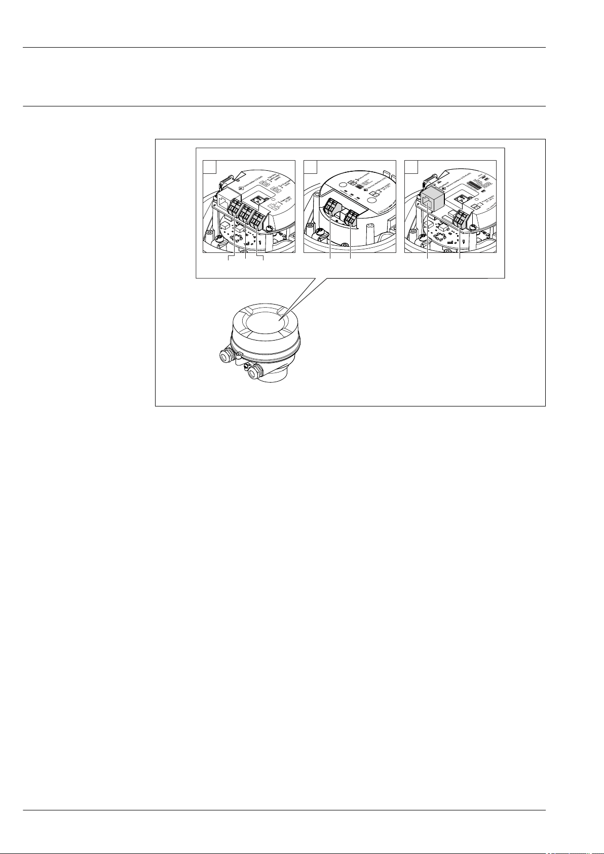
Terminal assignment Overview: housing version - terminals/device plugs
Proline Promag P 100
A0019825
A Housing version: compact, aluminum coated
1 Connection version: 4-20 mA HART, pulse/frequency/switch output
1.1 Signal transmission: pulse/frequency/switch output
1.2 Signal transmission: 4-20 mA HART
1.3 Supply voltage
2 Connection version: Modbus RS485, PROFIBUS DP
2.1 Signal transmission
2.2 Supply voltage
3 Connection version: EtherNet/IP
3.1 Signal transmission
3.2 Supply voltage
16 Endress+Hauser
Proline Promag P 100
L
L
26
27
+
_
24
25
1
2
+
_
+
_
1
2
3
Transmitter
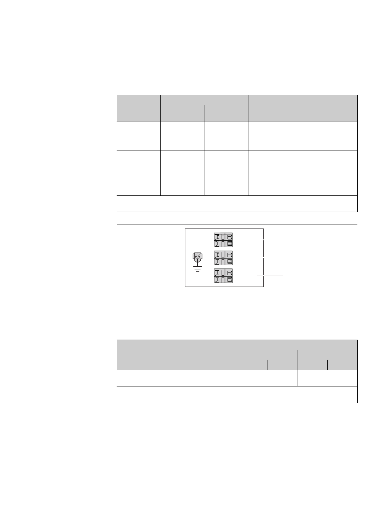
Connection version 4-20 mA HART with pulse/frequency/switch output
Order code for "Output", option B
Depending on the housing version, the transmitters can be ordered with terminals or device plugs.
Order code for
"Housing"
Outputs
Power
supply
Possible options for order code
"Electrical connection"
Option A Terminals Terminals • Option A: coupling M20x1
• Option B: thread M20x1
• Option C: thread G ½"
• Option D: thread NPT ½"
Connection methods available
Option A Device plug
(→ 20)
Terminals • Option L: plug M12x1 + thread NPT ½"
• Option N: plug M12x1 + coupling M20
• Option P: plug M12x1 + thread G ½"
• Option U: plug M12x1 + thread M20
Option A Device plug
(→ 20)
Device plug
(→ 20)
Option Q: 2 x plug M12x1
Order code for "Housing":
Option A: compact, coated aluminum
A0016888
2 Terminal assignment 4-20 mA HART with pulse/frequency/switch output
1 Power supply: DC 24 V
2 Output 1: 4-20 mA HART (active)
3 Output 2: pulse/frequency/switch output (passive)
Terminal number
Order code for
"Output"
Power supply Output 1 Output 2
2 (L-) 1 (L+) 27 (–) 26 (+) 25 (–) 24 (+)
Option B DC 24 V 4-20 mA HART (active) Pulse/frequency/switch
output (passive)
Order code for "Output":
Option B: 4-20 mA HART with pulse/frequency/switch output
Endress+Hauser 17
Proline Promag P 100
L
L
26
27AB
1
2
+
_
1
2
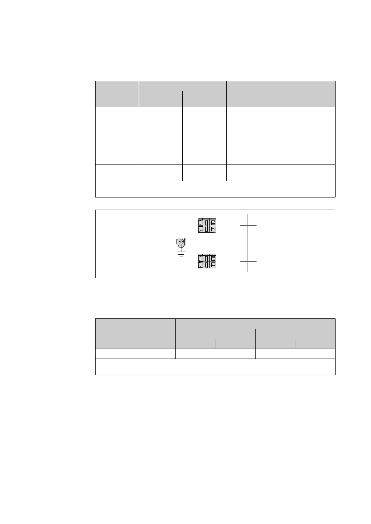
PROFIBUS DP connection version for use in non-hazardous areas and Zone 2/Div. 2
Order code for "Output", option L
Depending on the housing version, the transmitters can be ordered with terminals or device plugs.
Order code for
"Housing"
Output
Power
supply
Possible options for order code
"Electrical connection"
Option A Terminals Terminals • Option A: coupling M20x1
• Option B: thread M20x1
• Option C: thread G ½"
• Option D: thread NPT ½"
Connection methods available
Option A Device plug
(→ 21)
Terminals • Option L: plug M12x1 + thread NPT ½"
• Option N: plug M12x1 + coupling M20
• Option P: plug M12x1 + thread G ½"
• Option U: plug M12x1 + thread M20
Option A Device plug
(→ 21)
Device plug
(→ 21)
Option Q: 2 x plug M12x1
Order code for "Housing":
Option A: compact, coated aluminum
3 PROFIBUS DP terminal assignment
1 Power supply: DC 24 V
2 PROFIBUS DP
Terminal number
Order code for
"Output"
Power supply Output
2 (L-) 1 (L+) 27 (B) 26 (A)
Option L DC 24 V PROFIBUS DP
Order code for "Output":
Option L: PROFIBUS DP, for use in non-hazardous areas and Zone 2/div. 2
A0019528
18 Endress+Hauser
 Loading...