

Endress+Hauser Proline Promag 50 Operating Instructions Manual
Operating Instructions
Proline Promag 50
HART
Electromagnetic flow measuring system
6
BA00046D/06/EN/14.11
71136623
Valid as of version
V 2.03.XX (device software)


Promag 50 Table of contents
Table of contents
1 Safety instructions . . . . . . . . . . . . . . . . 5
1.1 Designated use . . . . . . . . . . . . . . . . . . . . . . . . . . . . 5
1.2 Installation, commissioning and operation . . . . . . . . 5
1.3 Operational safety . . . . . . . . . . . . . . . . . . . . . . . . . . 5
1.4 Return . . . . . . . . . . . . . . . . . . . . . . . . . . . . . . . . . . . 6
1.5 Notes on safety conventions and icons . . . . . . . . . . . 6
2 Identification . . . . . . . . . . . . . . . . . . . . 7
2.1 Device designation . . . . . . . . . . . . . . . . . . . . . . . . . 7
2.1.1 Nameplate of the transmitter . . . . . . . . . . . . 7
2.1.2 Nameplate of the sensor . . . . . . . . . . . . . . . 8
2.1.3 Nameplate, connections . . . . . . . . . . . . . . . 9
2.2 Certificates and approvals . . . . . . . . . . . . . . . . . . . . 9
2.3 Registered trademarks . . . . . . . . . . . . . . . . . . . . . . 10
3 Installation . . . . . . . . . . . . . . . . . . . . . 11
3.1 Incoming acceptance, transport and storage . . . . . . 11
3.1.1 Incoming acceptance . . . . . . . . . . . . . . . . . 11
3.1.2 Transport . . . . . . . . . . . . . . . . . . . . . . . . . 11
3.1.3 Storage . . . . . . . . . . . . . . . . . . . . . . . . . . . 12
3.2 Installation conditions . . . . . . . . . . . . . . . . . . . . . . 13
3.2.1 Dimensions . . . . . . . . . . . . . . . . . . . . . . . . 13
3.2.2 Mounting location . . . . . . . . . . . . . . . . . . . 13
3.2.3 Orientation . . . . . . . . . . . . . . . . . . . . . . . . 15
3.2.4 Vibrations . . . . . . . . . . . . . . . . . . . . . . . . . 16
3.2.5 Foundations, supports . . . . . . . . . . . . . . . . 17
3.2.6 Adapters . . . . . . . . . . . . . . . . . . . . . . . . . . 17
3.2.7 Nominal diameter and flow rate . . . . . . . . 18
3.2.8 Length of connecting cable . . . . . . . . . . . . 20
3.3 Installation instructions . . . . . . . . . . . . . . . . . . . . . 21
3.3.1 Installing the Promag D sensor . . . . . . . . . . 21
3.3.2 Installing the Promag L sensor . . . . . . . . . . 24
3.3.3 Installing the Promag W sensor . . . . . . . . . 27
3.3.4 Installing the Promag P sensor . . . . . . . . . . 32
3.3.5 Installing the Promag H sensor . . . . . . . . . . 36
3.3.6 Turning the transmitter housing . . . . . . . . 39
3.3.7 Turning the onsite display . . . . . . . . . . . . . 40
3.3.8 Installing the wall-mount housing . . . . . . . 41
3.4 Post-installation check . . . . . . . . . . . . . . . . . . . . . . 43
4 Wiring . . . . . . . . . . . . . . . . . . . . . . . . 44
4.1 Connecting the remote version . . . . . . . . . . . . . . . 44
4.1.1 Connecting Promag D, L, W, P, H . . . . . . 44
4.1.2 Cable specifications . . . . . . . . . . . . . . . . . . 49
4.2 Connecting the measuring unit . . . . . . . . . . . . . . . 50
4.2.1 Connecting the transmitter . . . . . . . . . . . . 50
4.2.2 Terminal assignment . . . . . . . . . . . . . . . . . 52
4.2.3 HART connection . . . . . . . . . . . . . . . . . . . 52
4.3 Potential equalization . . . . . . . . . . . . . . . . . . . . . . 53
4.3.1 Potential equalization for Promag D . . . . . . 53
4.3.2 Potential equalization for Promag W, P, L . 53
4.3.3 Potential equalization for Promag H . . . . . . 53
4.3.4 Exampels for potential equalization connections
for Promag D . . . . . . . . . . . . . . . . . . . . . . . 54
4.3.5 Exampels for potential equalization connections
for Promag L, W, P . . . . . . . . . . . . . . . . . . 55
4.4 Degree of protection . . . . . . . . . . . . . . . . . . . . . . . 56
4.5 Post-connection check . . . . . . . . . . . . . . . . . . . . . . 57
5 Operation . . . . . . . . . . . . . . . . . . . . . . 58
5.1 Display and operating elements . . . . . . . . . . . . . . . 58
5.2 Brief operating instructions on the function matrix . 59
5.2.1 General notes . . . . . . . . . . . . . . . . . . . . . . 60
5.2.2 Enabling the programming mode . . . . . . . . 60
5.2.3 Disabling the programming mode . . . . . . . . 60
5.3 Displaying error messages . . . . . . . . . . . . . . . . . . . 61
5.3.1 Type of error . . . . . . . . . . . . . . . . . . . . . . . 61
5.3.2 Error message types . . . . . . . . . . . . . . . . . . 61
5.4 Communication . . . . . . . . . . . . . . . . . . . . . . . . . . . 62
5.4.1 Operating options . . . . . . . . . . . . . . . . . . . 62
5.4.2 Current device description files . . . . . . . . . 63
5.4.3 Device variables . . . . . . . . . . . . . . . . . . . . . 63
5.4.4 Switching HART write protection on/off . . 63
5.4.5 Universal and common practice HART
commands . . . . . . . . . . . . . . . . . . . . . . . . . 64
5.4.6 Device status and error messages . . . . . . . . 68
6 Commissioning . . . . . . . . . . . . . . . . . . 70
6.1 Function check . . . . . . . . . . . . . . . . . . . . . . . . . . . 70
6.2 Switching on the measuring device . . . . . . . . . . . . 70
6.3 Quick Setup . . . . . . . . . . . . . . . . . . . . . . . . . . . . . . 71
6.3.1 "Commissioning" Quick Setup menu . . . . . 71
6.4 Configuration . . . . . . . . . . . . . . . . . . . . . . . . . . . . 72
6.4.1 Current output: active/passive . . . . . . . . . . 72
6.5 Adjustment . . . . . . . . . . . . . . . . . . . . . . . . . . . . . . 73
6.5.1 Empty-pipe/full-pipe adjustment . . . . . . . . 73
6.6 Data storage device (HistoROM) . . . . . . . . . . . . . . 74
6.6.1 HistoROM/S-DAT (sensor-DAT) . . . . . . . . 74
7 Maintenance . . . . . . . . . . . . . . . . . . . . 75
7.1 Exterior cleaning . . . . . . . . . . . . . . . . . . . . . . . . . . 75
7.2 Seals . . . . . . . . . . . . . . . . . . . . . . . . . . . . . . . . . . . 75
8 Accessories . . . . . . . . . . . . . . . . . . . . . 76
8.1 Device-specific accessories . . . . . . . . . . . . . . . . . . . 76
8.2 Measuring principle-specific accessories . . . . . . . . . 76
8.3 Communication-specific accessories . . . . . . . . . . . . 77
8.4 Service-specific accessories . . . . . . . . . . . . . . . . . . . 78
9 Troubleshooting . . . . . . . . . . . . . . . . . 79
9.1 Troubleshooting instructions . . . . . . . . . . . . . . . . . 79
9.2 System error messages . . . . . . . . . . . . . . . . . . . . . . 80
9.3 Process error messages . . . . . . . . . . . . . . . . . . . . . . 82
9.4 Process errors without messages . . . . . . . . . . . . . . 83
9.5 Response of outputs to errors . . . . . . . . . . . . . . . . . 84
9.6 Spare parts . . . . . . . . . . . . . . . . . . . . . . . . . . . . . . . 86
9.6.1 Removing and installing printed circuit boards 87
Endress+Hauser 3

Promag 50 Table of contents
9.6.2 Replacing the device fuse . . . . . . . . . . . . . . 91
9.6.3 Replacing the exchangeable electrode . . . . 92
9.7 Return . . . . . . . . . . . . . . . . . . . . . . . . . . . . . . . . . . 94
9.8 Disposal . . . . . . . . . . . . . . . . . . . . . . . . . . . . . . . . 94
9.9 Software history . . . . . . . . . . . . . . . . . . . . . . . . . . 94
10 Technical data . . . . . . . . . . . . . . . . . . . 96
10.1 Technical data at a glance . . . . . . . . . . . . . . . . . . . 96
10.1.1 Application . . . . . . . . . . . . . . . . . . . . . . . . 96
10.1.2 Function and system design . . . . . . . . . . . . 96
10.1.3 Input . . . . . . . . . . . . . . . . . . . . . . . . . . . . . 96
10.1.4 Output . . . . . . . . . . . . . . . . . . . . . . . . . . . 96
10.1.5 Power supply . . . . . . . . . . . . . . . . . . . . . . . 97
10.1.6 Performance characteristics . . . . . . . . . . . . 98
10.1.7 Operating conditions: Installation . . . . . . . . 98
10.1.8 Operating conditions: Environment . . . . . . 99
10.1.9 Operating conditions: Process . . . . . . . . . 100
10.1.10 Mechanical construction . . . . . . . . . . . . . 105
10.1.11 Human interface . . . . . . . . . . . . . . . . . . . 114
10.1.12 Certificates and approvals . . . . . . . . . . . . 115
10.1.13 Ordering information . . . . . . . . . . . . . . . 116
10.1.14 Accessories . . . . . . . . . . . . . . . . . . . . . . . 116
10.1.15 Documentation . . . . . . . . . . . . . . . . . . . 116
Index . . . . . . . . . . . . . . . . . . . . . . . . . . . . . 117
4 Endress+Hauser

Promag 50 Safety instructions
1 Safety instructions
1.1 Designated use
The measuring device described in this Operating Manual is to be used only for measuring the flow
rate of conductive fluids in closed pipes.
A minimum conductivity of 20 μS/cm is required for measuring demineralized water. Most liquids
can be measured as of a minimum conductivity of 5 μS/cm.
Examples:
• Acids, alkalis,
• Drinking water, wastewater, sewage sludge,
• Milk, beer, wine, mineral water, etc.
Resulting from incorrect use or from use other than that designated the operational safety of the
measuring devices can be suspended. The manufacturer accepts no liability for damages being
produced from this.
1.2 Installation, commissioning and operation
Please note the following:
• Installation, connection to the electricity supply, commissioning and maintenance of the device
must be carried out by trained, qualified specialists authorized to perform such work by the
facility's owner-operator. The specialist must have read and understood this Operating Manual
and must follow the instructions it contains.
• The device must be operated by persons authorized and trained by the facility's owner-operator.
Strict compliance with the instructions in the Operating Manual is mandatory.
• With regard to special fluids, including fluids used for cleaning, Endress+Hauser will be happy to
assist in clarifying the corrosion-resistant properties of wetted materials.
However, minor changes in temperature, concentration or in the degree of contamination in the
process may result in variations in corrosion resistance. For this reason, Endress+Hauser does not
accept any responsibility with regard to the corrosion resistance of wetted materials in a specific
application.
The user is responsible for the choice of suitable wetted materials in the process.
• If welding work is performed on the piping system, do not ground the welding appliance through
the Promag flowmeter.
• The installer must ensure that the measuring system is correctly wired in accordance with the
wiring diagrams. The transmitter must be grounded apart from when special protective measures
are taken (e.g. galvanically isolated SELV or PELV power supply)
• Invariably, local regulations governing the opening and repair of electrical devices apply.
1.3 Operational safety
Please note the following:
• Measuring systems for use in hazardous environments are accompanied by separate Ex
documentation, which is an integral part of this Operating Manual. Strict compliance with the
installation instructions and ratings as stated in this supplementary
documentation is mandatory. The symbol on the front of this Ex documentation indicates the
approval and the certification body (e.g.
• The measuring device complies with the general safety requirements in accordance with
EN 61010-1, the EMC requirements of IEC/EN 61326 and NAMUR Recommendations NE 21
and NE 43.
• Depending on the application, the seals of the process connections of the Promag H sensor require
periodic replacement.
0 Europe, 2 USA, 1 Canada).
Endress+Hauser 5

Safety instructions Promag 50
• When hot fluid passes through the measuring tube, the surface temperature of the housing
increases. In the case of the sensor, in particular, users should expect temperatures that can be
close to the fluid temperature. If the temperature of the fluid is high, implement sufficient
measures to prevent burning or scalding.
• The manufacturer reserves the right to modify technical data without prior notice. Your
Endress+Hauser distributor will supply you with current information and updates to these
Operating Instructions.
1.4 Return
• Do not return a measuring device if you are not absolutely certain that all traces of hazardous
substances have been removed, e.g. substances which have penetrated crevices or diffused
through plastic.
• Costs incurred for waste disposal and injury (burns, etc.) due to inadequate cleaning will be
charged to the owner-operator.
1.5 Notes on safety conventions and icons
The devices are designed to meet state-of-the-art safety requirements, have been tested, and left the
factory in a condition in which they are safe to operate. The devices comply with the applicable
standards and regulations in accordance with EN 61010-1 "Safety requirements for electrical
equipment for measurement, control and laboratory use".
The devices can, however, be a source of danger if used incorrectly or for anything other than the
designated use. Consequently, always pay particular attention to the safety instructions indicated in
this Operating Manual by the following icons:
#
Warning!
"Warning" indicates an action or procedure which, if not performed correctly, can result in injury
or a safety hazard. Comply strictly with the instructions and proceed with care.
Caution!
"
"Caution" indicates an action or procedure which, if not performed correctly, can result in incorrect
operation or destruction of the device. Comply strictly with the instructions.
!
Note!
"Note" indicates an action or procedure which, if not performed correctly, can have an indirect
effect on operation or trigger an unexpected response on the part of the device.
6 Endress+Hauser
Promag 50 Identification
Promag 50
-20°C (-4°F) <Tamb<+60°C (+140°F)
IP67 / NEMA/Type 4XOrder Code:
Ser.No.:
TAG No.:
50PXX-XXXXXXXXXXXX
12345678901
ABCDEFGHJKLMNPQRST
20-55VAC/16-62VDC
50-60Hz
I-OUT (HART), f-OUT
15VA/W
i
EPD / MSÜ
STATUS-IN
2
3
4
5
9
8
1
N12895
ECC
6
7
2 Identification
2.1 Device designation
The flow measuring system consists of the following components:
• Promag 50 transmitter
• Promag D, Promag L, Promag W, Promag P or Promag H sensor
In the compact version, the transmitter and sensor form a single mechanical unit; in the remote
version they are installed separately.
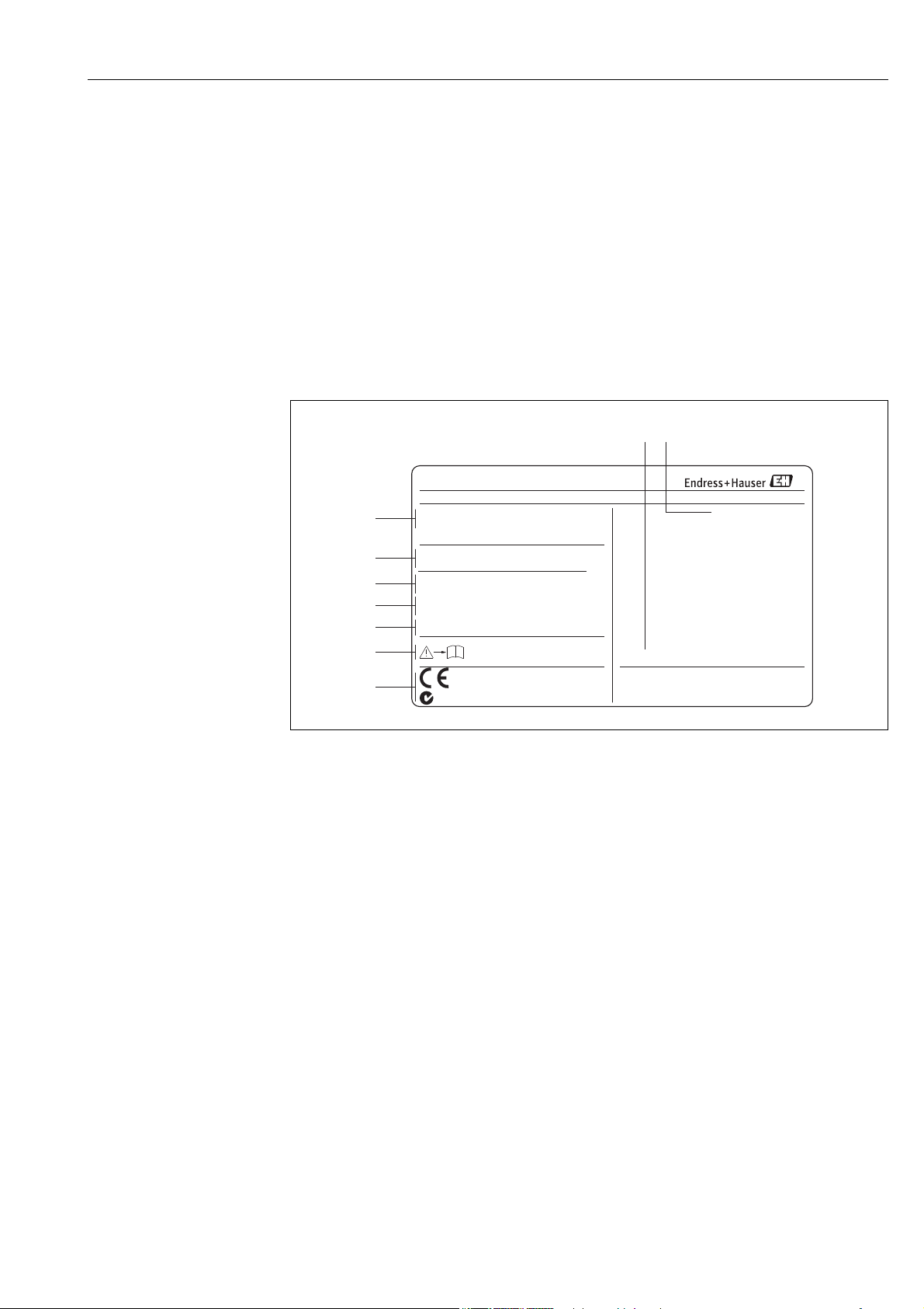
2.1.1 Nameplate of the transmitter
A0005412
Fig. 1: Nameplate specifications for the "Promag 50" transmitter (example)
1 Ordering code/serial number: See the specifications on the order confirmation for the meanings of the individual
letters and digits.
2 Power supply, frequency, power consumption
3 Additional information:
EPD/MSÜ: with Empty Pipe Detection
ECC: with electrode cleaning
4 Outputs available:
I-OUT (HART): with current output (HART)
f-OUT (HART): with frequency output
STATUS-IN: with status input (power supply)
5Reserved for information on special products
6 Observe device documentation
7 Reserved for additional information on device version (approvals, certificates)
8 Permitted ambient temperature range
9 Degree of protection
Endress+Hauser 7
Identification Promag 50
-20°C (-4°F)<Tamb<+60°C (+140°F) NEMA/Type4X
50PXX-XXXXXXXXXXXX
1.0000/0000
–10 ...150°C/+14 ...300°F°C °F
PFA
12345678901 RY
ABCDEFGHJKLMNPQRST
DN100 DIN EN PN40/ pnom =PS= 40bar
EPD/MSÜ, R/B
TM:
Order Code:
Materials:
K-factor:
Ser.No.:
TAG No.:
PROMAG P
1
2
3
7
13
12
1.4435/316L
Electrodes:
0.2% CAL
4
5
6
10
11
i
9
8
IP67
2007
N12895
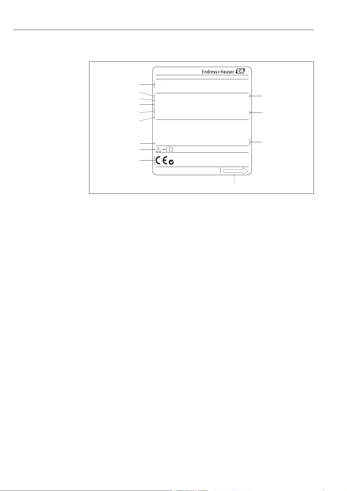
2.1.2 Nameplate of the sensor
A0004374
Fig. 2: Nameplate specifications for the "Promag" sensor (example)
1 Ordering code/serial number: See the specifications on the order confirmation for the meanings of the individual
letters and digits.
2 Calibration factor with zero point
3 Nominal diameter / Pressure rating
4 Fluid temperature range
5 Materials: lining/measuring electrodes
6Reserved for information on special products
7 Permitted ambient temperature range
8 Observe device documentation
9 Reserved for additional information on device version (approvals, certificates)
10 Calibration tolerance
11 Additional information (examples):
– EPD/MSÜ: with Empty Pipe Detection electrode
– R/B: with reference electrode
12 Degree of protection
13 Flow direction
8 Endress+Hauser
Promag 50 Identification
Communication:
Drivers:
Device SW:
ID xxxx (HEX)
XX.XX.XX (WEA)
XXXXXXXXXX
Date: DD.MMM.YYYY
Ex-works / ab-Werk/réglages usine
26(+) / 27(-)
NC:
Versorgung /
Tension d'alimentation
Observer manuel d'instruction
See operating manual
Betriebsanleitung beachten
Active: 0/4...20mA, RL max. = 700 Ohm
Passive: 4...20mA, max. 30VDC
Passive: 30VDC, 250mA
Active: 24VDC/25mA (max. 250mA/20ms)
Passive: 30VDC, 250mA
(HART:RL.min.=250 OHM)
fmax=1kHz
3...30VDC, Ri = 5kOhm
f-OUT
I-
OUT (HART)
12345678912Ser.No.:
Supply /
24(+) / 25(-)
22(+) / 23(-)
20(+) / 21(-)
N/LPE
A:
NO:
P:
L1/L+
12
319475-00XX
A
P
active
passive
normally open contact
normallyclosed contact
X
STATUS-OUT
STATUS-IN
X
Update 1 Update 2
2
3
1
4
5
6
7
8
9
10
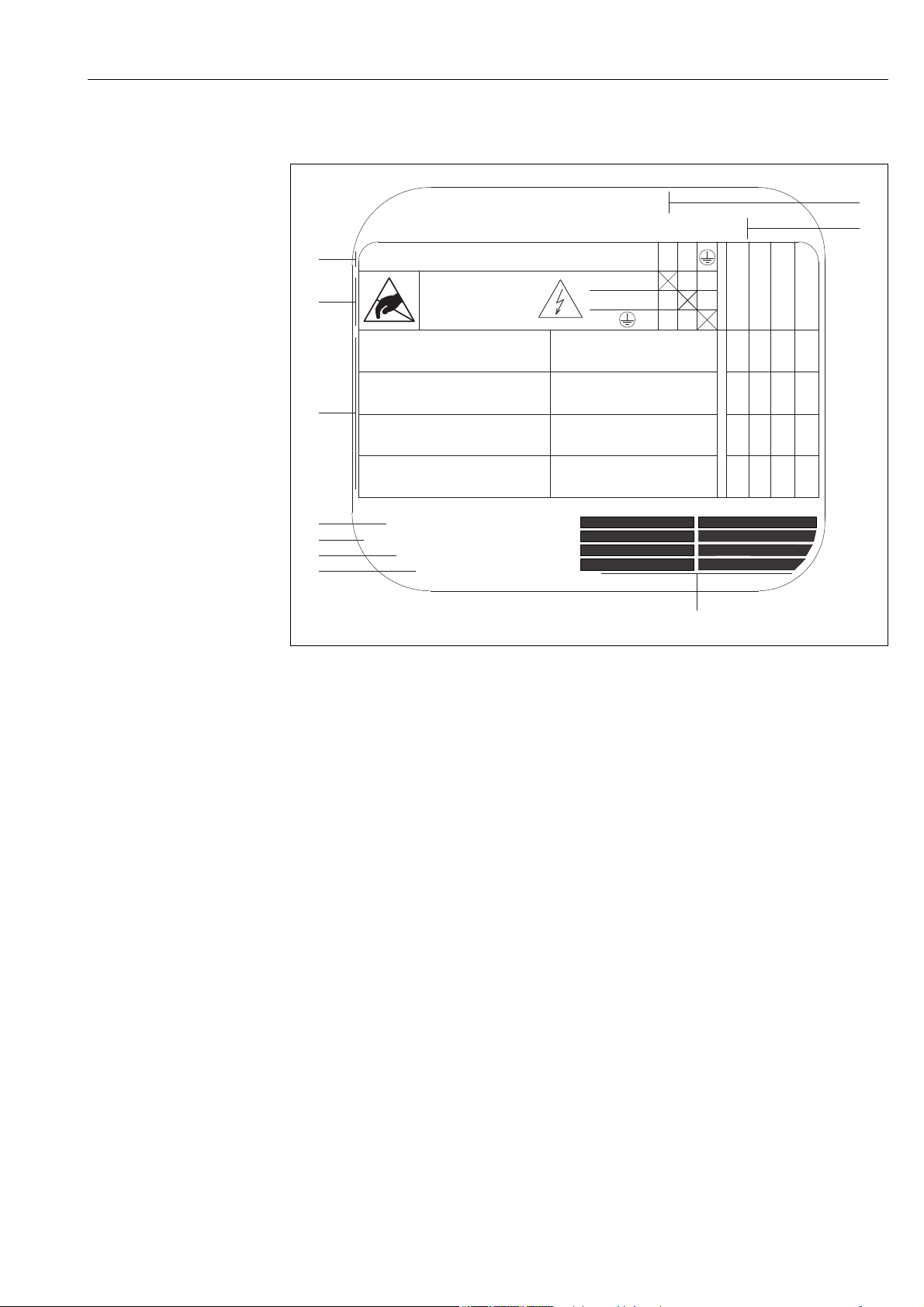
2.1.3 Nameplate, connections
A0000963
Fig. 3: Nameplate specifications for transmitter (example)
1 Serial number
2 Possible configuration of current output
3 Possible configuration of relay contacts
4 Terminal assignment, cable for power supply: 85 to 260 V AC, 20 to 55 V AC, 16 to 62 V DC
Terminal No. 1: L1 for AC, L+ for DC
Terminal No. 2: N for AC, L– for DC
5 Signals present at inputs and outputs, possible configuration and terminal assignment (20 to 27),
see also "Electrical values of inputs/outputs"
6 Version of device software currently installed
7 Installed communication type, e.g.: HART, PROFIBUS PA, etc.
8 Information on current communication software (Device Revision and Device Description), e.g.:
Dev. 01 / DD 01 for HART
9 Date of installation
Endress+Hauser 9
10 Current updates to data specified in points 6 to 9
2.2 Certificates and approvals
The devices are designed to meet state-of-the-art safety requirements in accordance with sound
engineering practice. They have been tested and left the factory in a condition in which they are
safe to operate.
The devices comply with the applicable standards and regulations in accordance with EN 61010-1
"Safety requirements for electrical equipment for measurement, control and laboratory use" and
with the EMC requirements of IEC/EN 61326/A1.
The measuring system described in this Operating Manual is therefore in conformity with the
statutory requirements of the EC Directives. Endress+Hauser confirms successful testing of the
device by affixing to it the CE mark.
The measuring system meets the EMC requirements of the Australian Communications and Media
Authority (ACMA)

Identification Promag 50
2.3 Registered trademarks
KALREZ® and VITON
Registered trademarks of E.I. Du Pont de Nemours & Co., Wilmington, USA
TRI-CLAMP
®
Registered trademark of Ladish & Co., Inc., Kenosha, USA
®
HART
Registered trademark of the HART Communication Foundation, Austin, USA
HistoROM™, S-DAT®, Field Xpert™, FieldCare
Registered or registration-pending trademarks of Endress+Hauser Flowtec AG, Reinach, CH
®
®
, Fieldcheck®, Applicator
®
10 Endress+Hauser

Promag 50 Installation
3 Installation
3.1 Incoming acceptance, transport and storage
3.1.1 Incoming acceptance
On receipt of the goods, check the following:
• Check the packaging and the contents for damage.
• Check the shipment, make sure nothing is missing and that the scope of supply matches your
order.
3.1.2 Transport
The following instructions apply to unpacking and to transporting the device to its final location:
• Transport the devices in the containers in which they are delivered.
• Do not remove the protective plates or caps on the process connections until you are ready to
install the device. This is particularly important in the case of sensors with PTFE linings.
Special notes on flanged devices
Caution!
"
• The wooden covers mounted on the flanges from the factory protect the linings on the flanges
during storage and transportation. In case of Promag L they are additionally used to hold the lap
joint flanges in place. Do not remove these covers until immediately before the device in the
pipe.
• Do not lift flanged devices by the transmitter housing, or the connection housing in the case of
the remote version.
#
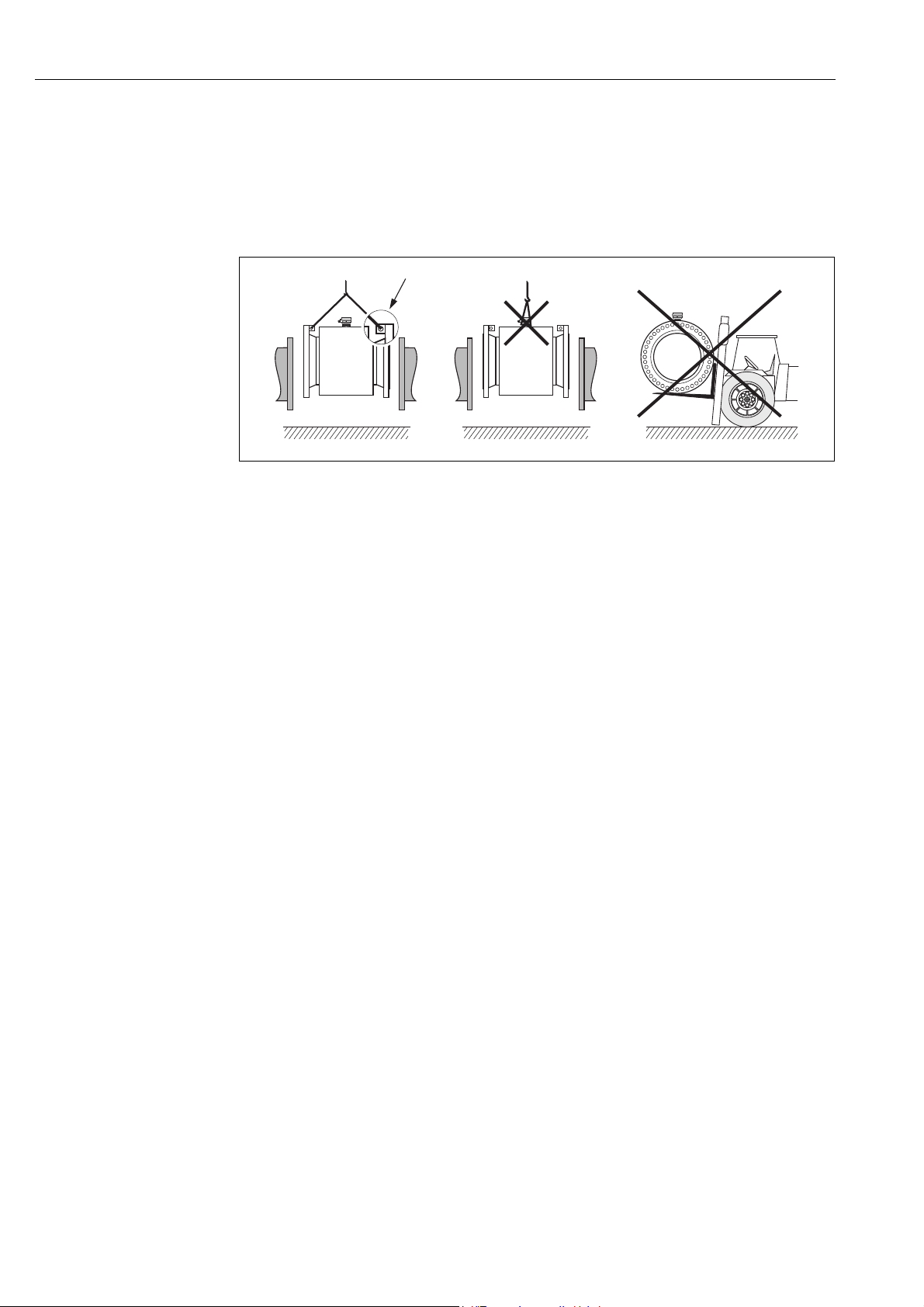
Transporting flanged devices DN 300 (12")
Use webbing slings slung round the two process connections. Do not use chains, as they could
damage the housing.
Warning!
Risk of injury if the measuring device slips. The center of gravity of the assembled measuring device
might be higher than the points around which the slings are slung.
At all times, therefore, make sure that the device does not unexpectedly turn around its axis or slip.
a0004294
Fig. 4: Transporting sensors with DN 300 ( 12")
Endress+Hauser 11
Installation Promag 50
Transporting flangeddevices DN > 300 (> 12")
Use only the metal eyes on the flanges for transporting the device, lifting it and positioning the
sensor in the piping.
Caution!
"
Do not attempt to lift the sensor with the tines of a fork-lift truck beneath the metal casing. This
would buckle the casing and damage the internal magnetic coils.
a0004295
Fig. 5: Transporting sensors with DN > 300 (> 12")
3.1.3 Storage
Please note the following:
• Pack the measuring device in such a way as to protect it reliably against impact for storage
(and transportation). The original packaging provides optimum protection.
• The storage temperature corresponds to the operating temperature range of the measuring
transmitter and the appropriate measuring sensors ä 99.
• Do not remove the protective plates or caps on the process connections until you are ready to
install the device. This is particularly important in the case of sensors with PTFE linings.
• The measuring device must be protected against direct sunlight during storage in order to avoid
unacceptably high surface temperatures.
• Choose a storage location where moisture does not collect in the measuring device. This will help
prevent fungus and bacteria infestation which can damage the liner.
12 Endress+Hauser
Promag 50 Installation
h 2 x DN³
3.2 Installation conditions
3.2.1 Dimensions
The dimensions and installation lengths of the sensor and transmitter can be found in the "Technical
Information" for the device in question. This document can be downloaded as a PDF file from
www.endress.com. A list of the "Technical Information" documents available is provided in the
"Documentation" section on ä 116.
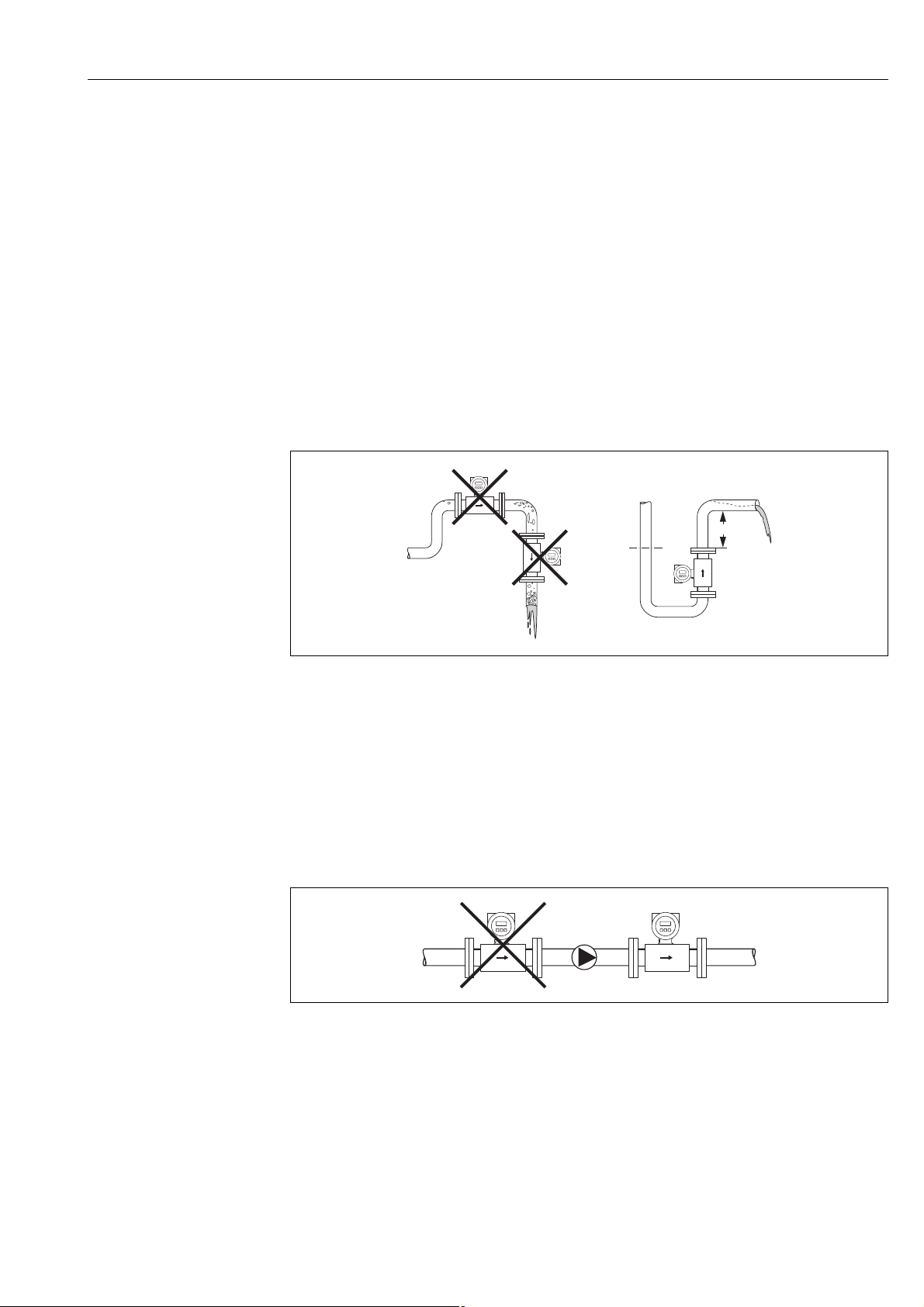
3.2.2 Mounting location
Entrained air or gas bubble formation in the measuring tube can result in an increase in measuring
errors.
Avoid the following locations:
• Highest point of a pipeline. Risk of air accumulating!
• Directly upstream from a free pipe outlet in a vertical pipeline.
A0008154
Fig. 6: Mounting location
Installation of pumps
Do not install the sensor on the intake side of a pump. This precaution is to avoid low pressure and
the consequent risk of damage to the lining of the measuring tube. Information on the lining's
resistance to partial vacuum can be found on ä 103.
It might be necessary to install pulse dampers in systems incorporating reciprocating, diaphragm or
peristaltic pumps. Information on the measuring system's resistance to vibration and shock can be
found on ä 99.
A0003203
Fig. 7: Installation of pumps
Endress+Hauser 13

Installation Promag 50
5 x DN
2 x DN
³
³
h
2
1
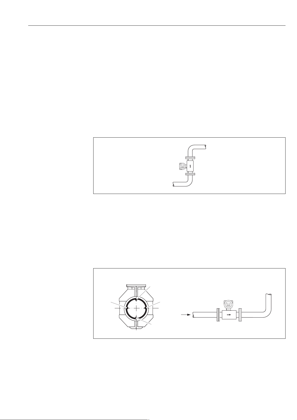
Partially filled pipes
Partially filled pipes with gradients necessitate a drain-type configuration.
The Empty Pipe Detection function (EPD ä 73) offers additional protection by detecting empty
or partially filled pipes.
Caution!
"
Risk of solids accumulating. Do not install the sensor at the lowest point in the drain. It is advisable
to install a cleaning valve.
A0008155
Fig. 8: Installation in a partially filled pipe
Down pipes
Install a siphon or a vent valve downstream of the sensor in down pipes whose length h 5 m
(16.4 ft). This precaution is to avoid low pressure and the consequent risk of damage to the lining
of the measuring tube.
This measure also prevents the system losing prime, which could cause air pockets. Information on
the lining's resistance to partial vacuum can be found on ä 103.
A0008157
Fig. 9: Measures for installation in a down pipe
1 Vent valve
2Pipe siphon
h Length of down pipe
14 Endress+Hauser
Promag 50 Installation
A
1
22
A
3
3.2.3 Orientation
An optimum orientation position helps avoid gas and air accumulations and deposits in the
measuring tube. However, Promag offers the additional Empty Pipe Detection (EPD) function to
ensure the detection of partially filled measuring tubes, e.g. in the case of degassing fluids or varying
process pressure:
• Electrode Cleaning Circuit (ECC) for applications with accretive fluids, e.g. electrically
conductive deposits ( "Description of Device Functions" manual).
• Empty Pipe Detection (EPD) ensures the detection of partially filled measuring tubes, e.g. in the
case of degassing fluids ( ä 73)
• Exchangeable Measuring Electrodes for abrasive fluids ( ä 92)
Vertical orientation
This is the ideal orientation for self-emptying piping systems and for use in conjunction with Empty
Pipe Detection.
Fig. 10: Vertical orientation
Horizontal orientation
The measuring electrode plane should be horizontal. This prevents brief insulation of the two
measuring electrodes by entrained air bubbles.
Caution!
"
Empty Pipe Detection functions correctly only when the measuring device is installed horizontally
and the transmitter housing is facing upward ( å 10). Otherwise there is no guarantee that
Empty Pipe Detection will respond if the measuring tube is only partially filled or empty.
A0008158
Fig. 11: Horizontal orientation
1 EPD electrode for the detection of empty pipes (not with Promag D and Promag H (DN 2 to 15; 1/12" to ½"))
2 Measuring electrodes for signal detection
3 Reference electrode for the potential equalization (not with Promag D and H)
Endress+Hauser 15
A0003207
Installation Promag 50
5 x DN³
³ 2 x DN
L
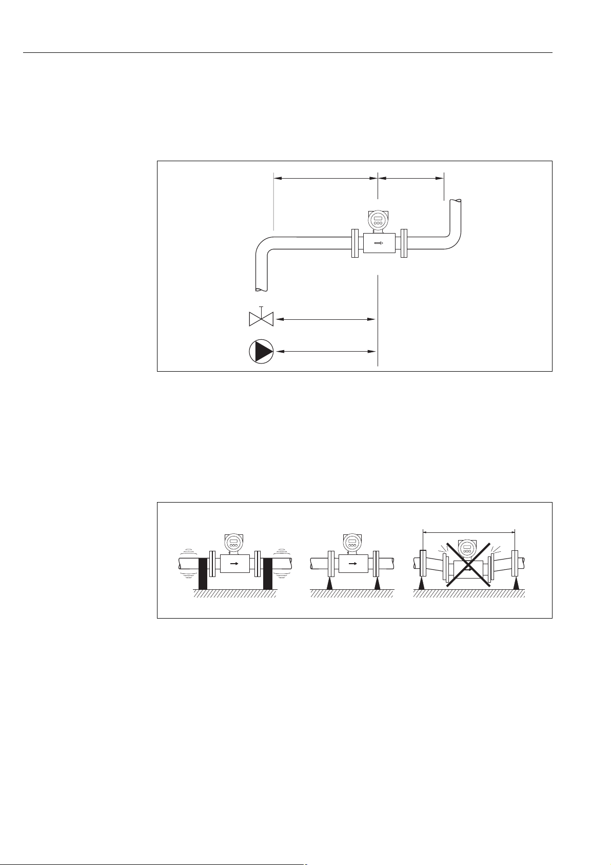
Inlet and outlet run
If possible, install the sensor upstream from fittings such as valves, T-pieces, elbows, etc. The
following inlet and outlet runs must be observed in order to meet accuracy specifications:
• Inlet run: 5 × DN
•Outlet run: 2 × DN
A0003210
Fig. 12: Inlet and outlet runs
3.2.4 Vibrations
Secure the piping and the sensor if vibration is severe.
Caution!
"
If vibrations are too severe, we recommend the sensor and transmitter be mounted separately.
Information on resistance to vibration and shock can be found on ä 99.
A0003208
Fig. 13: Measures to prevent vibration of the device (L > 10 m (32.8 ft))
16 Endress+Hauser

Promag 50 Installation
100
10
0.5
d / D
[mbar]
0.60.70.80.9
1m/s
2m/s
3m/s
4 m/s
5m/s
6m/s
7m/s
8m/s
1
D
d
max. 8°
3.2.5 Foundations, supports
If the nominal diameter is DN 350, mount the sensor on a foundation of adequate load-bearing
strength.
Caution!
"
Risk of damage.
Do not support the weight of the sensor on the metal casing: the casing would buckle and damage
the internal magnetic coils.
A0003209
Fig. 14: Correct support for large nominal diameters (DN 350)
!
3.2.6 Adapters
Suitable adapters to DIN EN 545 (double-flange reducers) can be used to install the sensor in largerdiameter pipes.
The resultant increase in the rate of flow improves measuring accuracy with very slow-moving
fluids. The nomogram shown here can be used to calculate the pressure loss caused by reducers and
expanders.
Note!
The nomogram only applies to liquids of viscosity similar to water.
1. Calculate the ratio of the diameters d/D.
2. From the nomogram read off the pressure loss as a function of flow velocity (downstream from
the reduction) and the d/D ratio.
Fig. 15: Pressure loss due to adapters
A0011907
Endress+Hauser 17

Installation Promag 50
3.2.7 Nominal diameter and flow rate
The diameter of the pipe and the flow rate determine the nominal diameter of the sensor. The
optimum velocity of flow is between 2 and 3 m/s (6.5 to 9.8 ft/s)
The velocity of flow (v), moreover, has to be matched to the physical properties of the fluid:
• v < 2 m/s (v < 6.5 ft/s): for abrasive fluids
• v > 2 m/s (v > 6.5 ft/s): for fluids producing buildup
!
Note!
Flow velocity can be increased, if necessary, by reducing the nominal diameter of the sensor
( ä 17).
Recommended flow (SI units)
Nominal
diameter
[mm] Min./max. full scale value (v 0.3 or 10 m/s) in [dm³/min]
2 – – – – 0.06 to 1.8
4 – – – – 0.25 to 7
8 – – – – 1 to 30
15 – – – 4 to 100 4 to 100
25 9 to 300 – 9 to 300 9 to 300 9 to 300
32 – – 15 to 500 15 to 500 –
40 25 to 700 – 25 to 700 25 to 700 25 to 700
50 35 to 1100 35 to 1100 35 to 1100 35 to 1100 35 to 1100
65 60 to 2000 60 to 2000 60 to 2000 60 to 2000 60 to 2000
80 90 to 3000 90 to 3000 90 to 3000 90 to 3000 90 to 3000
100 145 to 4700 145 to 4700 145 to 4700 145 to 4700 145 to 4700
125 – 220 to 7500 220 to 7500 220 to 7500 –
[mm] Min./max. full scale value (v 0.3 or 10 m/s) in [m³/h]
150 – 20 to 600 20 to 600 20 to 600 –
200 – 35 to 1100 35 to 1100 35 to 1100 –
250 – 55 to 1700 55 to 1700 55 to 1700 –
300 – 80 to 2400 80 to 2400 80 to 2400 –
350 – 110 to 3300 110 to 3300 110 to 3300 –
375 – 140 to 4200 140 to 4200 – –
400 – 140 to 4200 140 to 4200 140 to 4200 –
450 – 180 to 5400 180 to 5400 180 to 5400 –
500 – 220 to 6600 220 to 6600 220 to 6600 –
600 – 310 to 9600 310 to 9600 310 to 9600 –
700 – 420 to 13500 420 to 13500 – –
750 – 480 to 15200 480 to 15200 – –
800 – 550 to 18000 550 to 18000 – –
900 – 690 to 22500 690 to 22500 – –
1000 – 850 to 28000 850 to 28000 – –
1050 – 950 to 40000 950 to 40000 – –
1200 – 1250 to 40000 1250 to 40000 – –
1400 – – 1700 to 55000 – –
1600 – – 2200 to 70000 – –
1800 – – 2800 to 90000 – –
2000 – – 3400 to 110000 – –
Promag D Promag L Promag W Promag P Promag H
18 Endress+Hauser

Promag 50 Installation
Recommended flow (US units)
Nominal diameter Promag D Promag L Promag W Promag P Promag H
[inch] Min./max. full scale value (v 0.3 or 10 m/s) in [gal/min]
/" – – – – 0.015 to 0.5
1
/"–– – –0.07 to 2
/"–– – –0.25 to 8
/" – – – 1.0 to 27 1.0 to 27
1" 2.5 to 80 – 2.5 to 80 2.5 to 80 2.5 to 80
1
/" – – 4 to 130 4 to 130 –
/" 7 to 190 7 to 190 7 to 190 7 to 190 7 to 190
1
2" 10 to 300 10 to 300 10 to 300 10 to 300 10 to 300
2
/" 16 to 500 16 to 500 16 to 500 16 to 500 16 to 500
3" 24 to 800 24 to 800 24 to 800 24 to 800 24 to 800
4" 40 to 1250 40 to 1250 40 to 1250 40 to 1250 40 to 1250
5" – 60 to 1950 60 to 1950 60 to 1950 –
6" – 90 to 2650 90 to 2650 90 to 2650 –
8" – 155 to 4850 155 to 4850 155 to 4850 –
10" – 250 to 7500 250 to 7500 250 to 7500 –
12" – 350 to 10600 350 to 10600 350 to 10600 –
14" – 500 to 15000 500 to 15000 500 to 15000 –
15" – 600 to 19000 600 to 19000 – –
16" – 600 to 19000 600 to 19000 600 to 19000 –
18" – 800 to 24000 800 to 24000 800 to 24000 –
20" – 1000 to 30000 1000 to 30000 1000 to 30000 –
24" – 1400 to 44000 1400 to 44000 1400 to 44000 –
28" – 1900 to 60000 1900 to 60000 – –
30" – 2150 to 67000 2150 to 67000 – –
32" – 2450 to 80000 2450 to 80000 – –
36" – 3100 to 100000 3100 to 100000 – –
40" – 3800 to 125000 3800 to 125000 – –
42" – 4200 to 135000 4200 to 135000 – –
48" – 5500 to 175000 5500 to 175000 – –
[inch] Min./max. full scale value (v 0.3 or 10 m/s) in [Mgal/d]
54" – – 9 to 300 – –
60" – – 12 to 380 – –
66" – – 14 to 500 – –
72" – – 16 to 570 – –
78" – – 18 to 650 – –
Endress+Hauser 19
Installation Promag 50
200
100
5
10 100 200
L
max
[m][m]
[µS/cm]
L
max
[ft]
200 6000
400
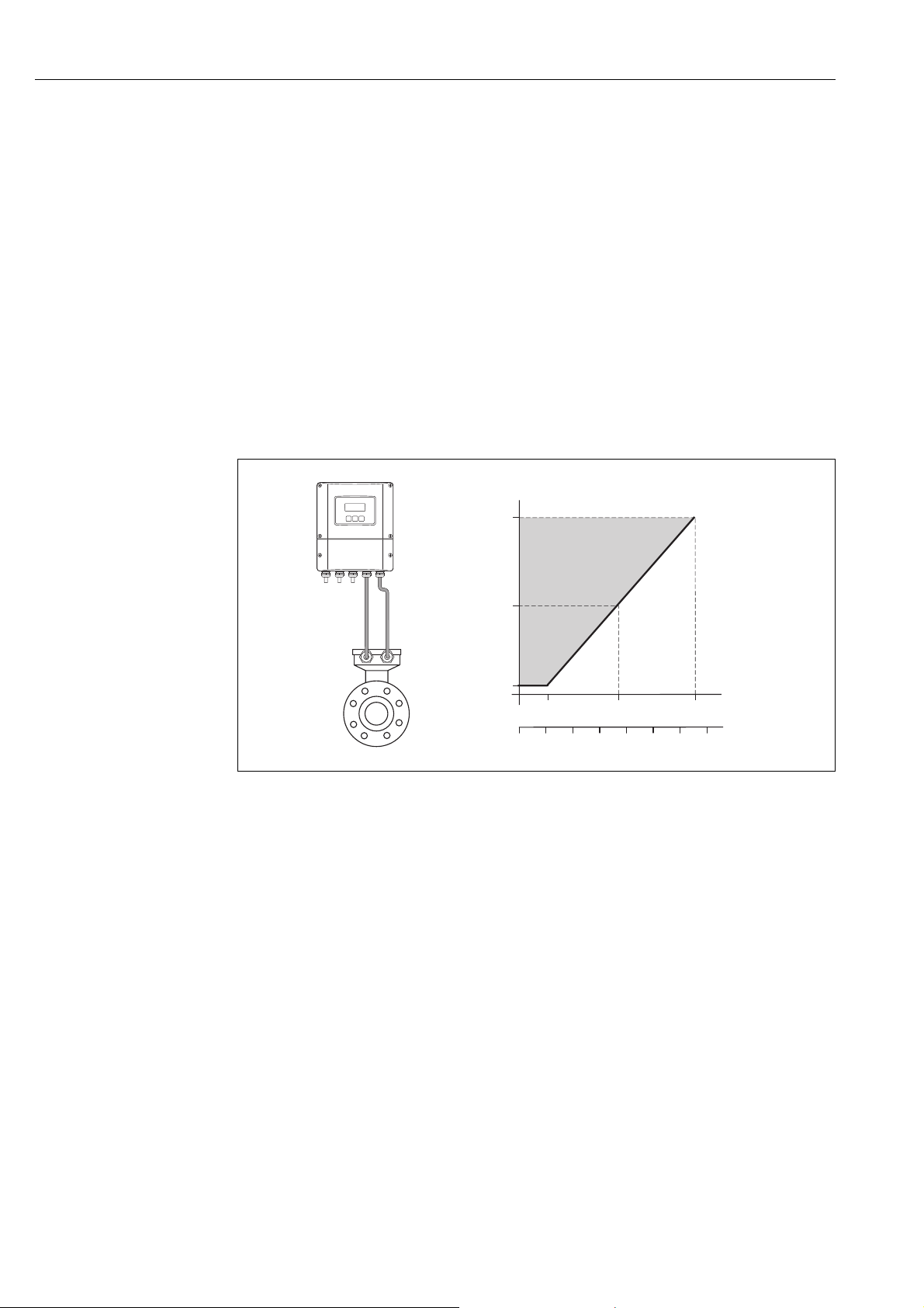
3.2.8 Length of connecting cable
In order to ensure measuring accuracy, comply with the following instructions when installing the
remote version:
• Fix cable run or lay in armored conduit. Cable movements can falsify the measuring signal
especially in the case of low fluid conductivities.
• Route the cable well clear of electrical machines and switching elements.
• Ensure potential equalization between sensor and transmitter, if necessary.
• The permitted connecting cable length L
is determined by the fluid conductivity ( å 16).
max
A minimum conductivity of 20 μS/cm is required for measuring demineralized water. Most
liquids can be measured as of a minimum conductivity of 5 μS/cm.
• The maximum connecting cable length is 10 m (32.8 ft) when empty pipe detection
(EPD ä 73) is switched on.
Fig. 16: Permissible cable length for the remote version
Area shaded gray = permitted range
Lmax = connecting cable length in [m]
Fluid conductivity in [μS/cm]
A0010734
20 Endress+Hauser
Promag 50 Installation
5
1
2
3
4
3.3 Installation instructions
3.3.1 Installing the Promag D sensor
The sensor is installed between the pipe flanges with a mounting kit. The device is centered using
recesses on the sensor ( ä 22).
!
"
Note!
A mounting kit consisting of mounting bolts, seals, nuts and washers can be ordered separately
( ä 76). Centering sleeves are provided with the device if they are required for the installation.
Caution!
When installing the transmitter in the pipe, observe the necessary torques ( ä 23).
a0010776
Fig. 17: Mounting the sensor
1Nut
2Washer
3 Mounting bolt
4 Centering sleeve
5Seal
Seals
When installing the sensor, make sure that the seals used do not project into the pipe cross-section.
Caution!
"
Risk of short circuit! Do not use electrically conductive sealing compounds such as graphite! An
electrically conductive layer could form on the inside of the measuring tube and short-circuit the
measuring signal.
!
Endress+Hauser 21
Note!
Use seals with a hardness rating of 70° Shore.
Installation Promag 50
1
1
1
1
1
1
1
1
1
1
1
1
2
2
22
3
3
3
3
3
3
3
3
1
1
1
1
1
1
1
1
1
1
1
1
1
1
1
1
1
1
1
1
1
1
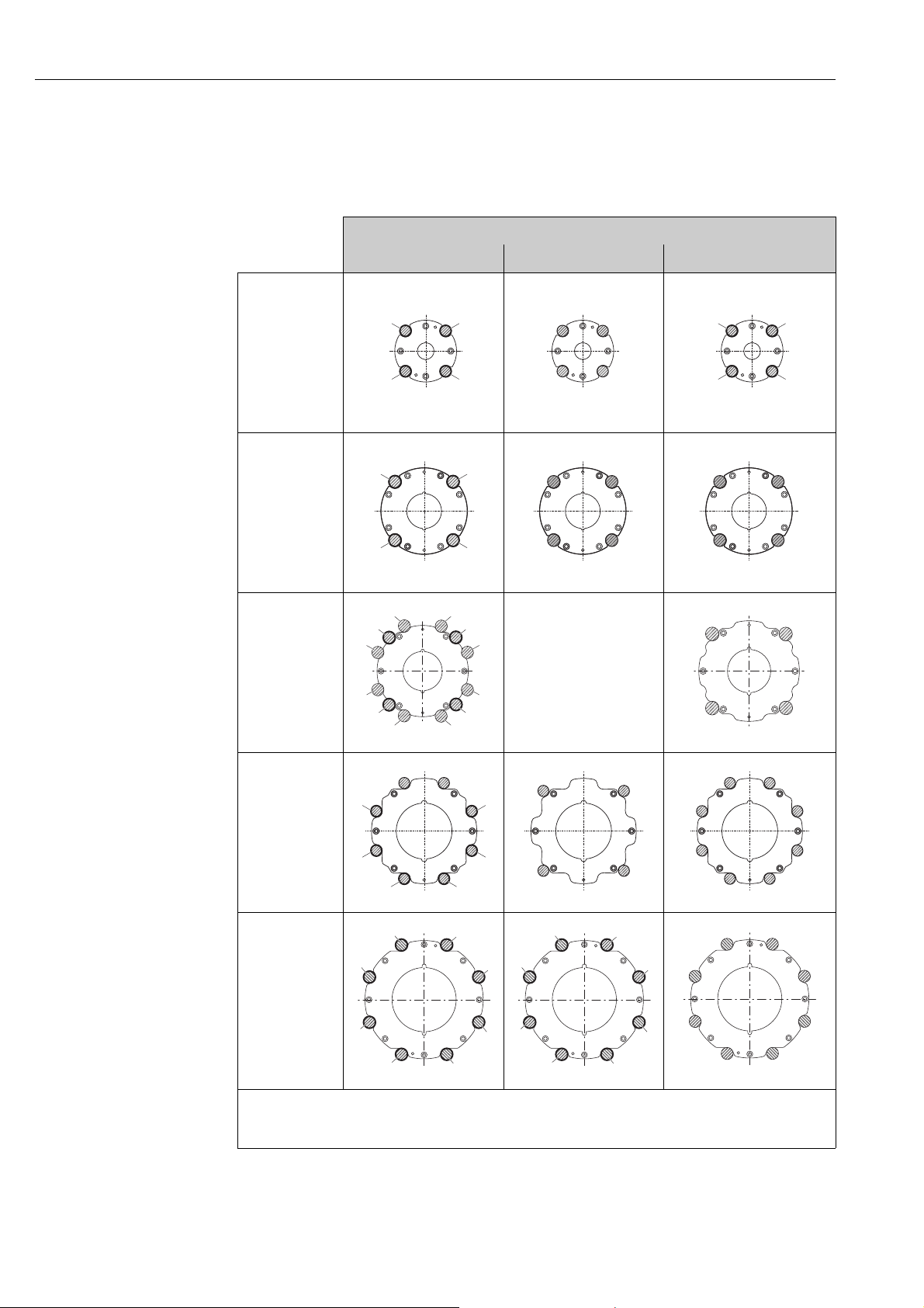
Arrangement of the mounting bolts and centering sleeves
The device is centered using recesses on the sensor. The arrangement of the mounting bolts and the
use of the centering sleeves supplied depend on the nominal diameter, the flange standard und the
pitch circle diameter.
Process connection
EN (DIN) ANSI JIS
DN 25 to 40
(DN 1" to 1 ½")
A0010896 A0010824 A0010896
DN 50
(DN 2")
DN 65
DN 80
(DN 3")
DN 100
(DN 4")
A0010897 A0010825 A0010825
–––––––––––––––––
A0012170
A0010898 A0010827 A0010826
A0012171
A0012168 A0012168 A0012169
1 = Mounting bolts with centering sleeves
2 = EN (DIN) flanges: 4-hole with centering sleeves
3 = EN (DIN) flanges: 8-hole without centering sleeves
22 Endress+Hauser

Promag 50 Installation
Screw tightening torques (Promag D)
Please note the following:
• The tightening torques listed below are for lubricated threads only.
• Always tighten the screws uniformly and in diagonally opposite sequence.
• Overtightening the screws will deform the sealing faces or damage the seals.
• The tightening torques listed below apply only to pipes not subjected to tensile stress.
The tightening torques apply to situations where an EPDM soft material flat seal (e.g. 70 Shore) is
used.
Tightening torques, mounting bolts and centering sleeves for EN (DIN) PN 16
Nominal
diameter
[mm] [mm] [mm] smooth seal face raised face
25 4 × M12 × 145 54 19 19
40 4 × M16 × 170 68 33 33
50 4 × M16 × 185 82 41 41
65
65
80 8 × M16 × 225 116 36 36
100 8 × M16 × 260 147 40 40
EN (DIN) flanges: 4-hole with centering sleeves
EN (DIN) flanges: 8-hole without centering sleeves
A centering sleeve is not required. The device is centered directly via the sensor housing.
Mounting bolts
4 × M16 × 200 92 44 44
8 × M16 × 200 –
Centering sleeve
length
Tightening torque [Nm]
with a process flange with a
29 29
Tightening torques, mounting bolts and centering sleeves for JIS 10 K
Nominal
diameter
[mm] [mm] [mm] smooth seal face raised face
25 4 × M16 × 170 54 24 24
40 4 × M16 × 170 68 32 25
50 4 × M16 × 185 – * 38 30
65 4 × M16 × 200 – * 42 42
80 8 × M16 × 225 – * 36 28
100 8 × M16 × 260 – * 39 37
* A centering sleeve is not required. The device is centered directly via the sensor housing.
Mounting bolts
Centering sleeve
length
Tightening torque [Nm]
with a process flange with a
Tightening torques, mounting bolts and centering sleeves for ANSI Class 150
Nominal
diameter
[inch] [inch] [inch] smooth seal face raised face
1" 4 × UNC 1/2" × 5.70" – * 14 7
1 ½" 4 × UNC 1/2" × 6.50" – * 21 14
2" 4 × UNC 5/8" × 7.50" – * 30 27
3" 4 × UNC 5/8" × 9.25" – * 31 31
4" 8 × UNC 5/8" × 10,4" 5,79 28 28
* A centering sleeve is not required. The device is centered directly via the sensor housing.
Mounting bolts
Centering sleeve
length
Tightening torque [lbf · ft]
with a process flange with a
Endress+Hauser 23
Installation Promag 50
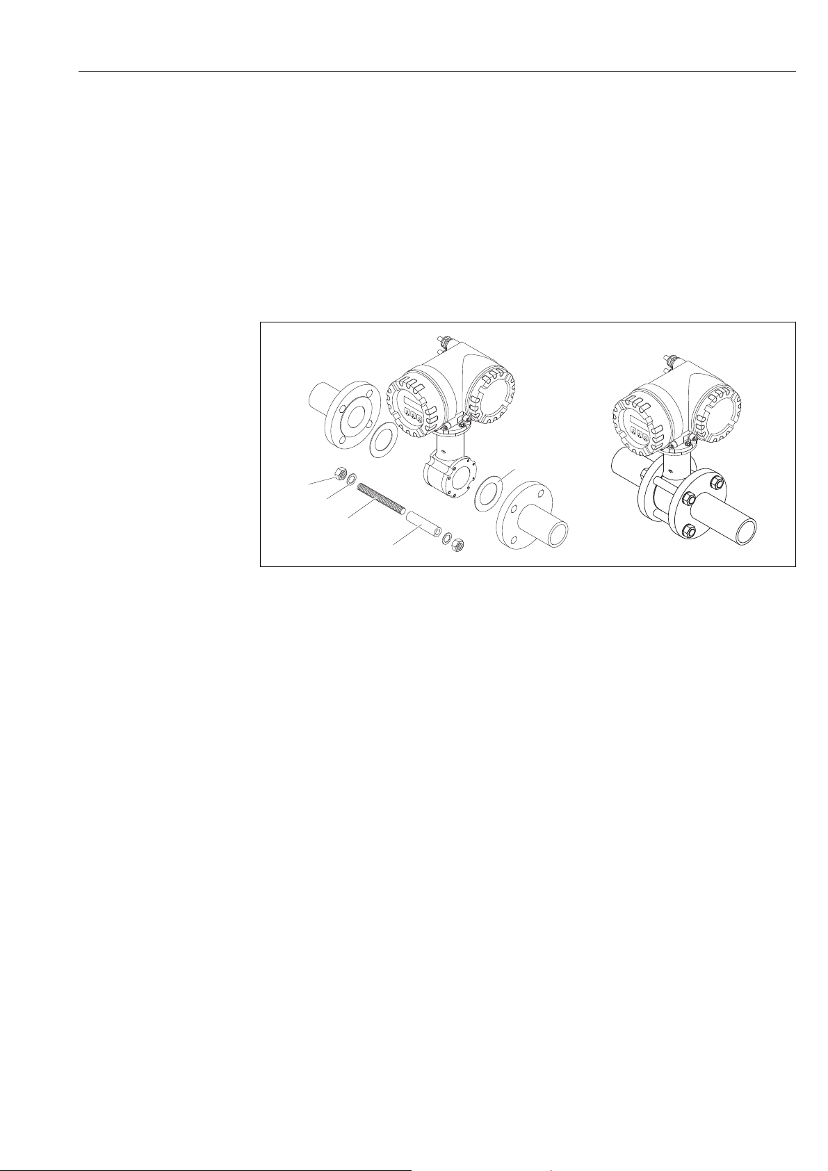
3.3.2 Installing the Promag L sensor
Caution!
"
• The protective covers mounted on the two sensor flanges (DN 50…300) are used to hold the lap
joint flanges in place and to protect the PTFE liner during transportation. Consequently, do not
remove these covers until immediately before the sensor is installed in the pipe.
• The covers must remain in place while the device is in storage.
• Make sure that the lining is not damaged or removed from the flanges.
!
Note!
Bolts, nuts, seals, etc. are not included in the scope of supply and must be supplied by the customer.
The sensor is designed for installation between the two piping flanges.
• Observe in any case the necessary screw tightening torques on ä 25
• If grounding disks are used, follow the mounting instructions which will be enclosed with the
shipment
• To comply with the device specification, a concentrical installation in the measuring section is
required
Fig. 18: Installing the Promag L sensor
Seals
Comply with the following instructions when installing seals:
• Hard rubber lining additional seals are always necessary.
• Polyurethane lining no seals are required.
• PTFE lining no seals are required.
• For DIN flanges, use only seals according to EN 1514-1.
• Make sure that the seals do not protrude into the piping cross-section.
Caution!
"
Risk of short circuit!
Do not use electrically conductive sealing compounds such as graphite! An electrically conductive
layer could form on the inside of the measuring tube and short-circuit the measuring signal.
Ground cable
• If necessary, special ground cables for potential equalization can be ordered as an accessory
( ä 76).
• Information on potential equalization and detailed mounting instructions for the use of ground
cables can be found on ä 55.
a0004296
24 Endress+Hauser

Promag 50 Installation
Screw tightening torques (Promag L)
Please note the following:
• The tightening torques listed below are for lubricated threads only.
• Always tighten the screws uniformly and in diagonally opposite sequence.
• Overtightening the screws will deform the sealing faces or damage the seals.
• The tightening torques listed below apply only to pipes not subjected to tensile stress.
Promag L tightening torques for EN (DIN)
Nominal diameter EN (DIN) Max. tightening torque
Hard rubber Polyurethane PTFE
[mm] Pressure rating
[bar]
50 PN 10/16 4 × M 16 - 15 40
65* PN 10/16 8 × M 16 - 10 22
80 PN 10/16 8 × M 16 - 15 30
100 PN 10/16 8 × M 16 - 20 42
125 PN 10/16 8 × M 16 - 30 55
150 PN 10/16 8 × M 20 - 50 90
200 PN 10 8 × M 20 - 65 130
250 PN 10 12 × M 20 - 50 90
300 PN 10 12 × M 20 - 55 100
350 PN 6 12 × M 20 111 120 350 PN 10 16 × M 20 112 118 400 PN 6 16 × M 20 90 98 400 PN 10 16 × M 24 151 167 450 PN 6 16 × M 20 112 126 450 PN 10 20 × M 24 153 133 500 PN 6 20 × M 20 119 123 500 PN 10 20 × M 24 155 171 600 PN 6 20 × M 24 139 147 600 PN 10 20 × M 27 206 219 700 PN 6 24 × M 24 148 139 700 PN 10 24 × M 27 246 246 800 PN 6 24 × M 27 206 182 800 PN 10 24 × M 30 331 316 900 PN 6 24 × M 27 230 637 900 PN 10 28 × M 30 316 307 -
1000 PN 6 28 × M 27 218 208 1000 PN 10 28 × M 33 402 405 1200 PN 6 32 × M 30 319 299 1200 PN 10 32 × M 36 564 568 -
* Designed acc. to EN 1092-1 (not to DIN 2501)
Threaded
fasteners
[Nm] [Nm] [Nm]
Promag L tightening torques for ANSI
Nominal diam-
eter
[mm] [inch] [lbs] [Nm] [lbf · ft] [Nm] [lbf · ft] [Nm] [lbf · ft]
50 2" Class 150 4 × 5/8" - - 15 11 40 29
80 3" Class 150 4 × 5/8" - - 25 18 65 48
100 4" Class 150 8 × 5/8" - - 20 15 44 32
150 6" Class 150 8 × ¾" - - 45 33 90 66
200 8" Class 150 8 × ¾" - - 65 48 125 92
250 10" Class 150 12 × 7/8" - - 55 41 100 74
300 12" Class 150 12 × 7/8" - - 68 56 115 85
350 14" Class 150 12 × 1" 135 100 158 117 - -
ANSI Threaded
fasteners
Pressure rating Hard rubber Polyurethane PTFE
Max. tightening torque
Endress+Hauser 25

Installation Promag 50
Nominal diam-
eter
[mm] [inch] [lbs] [Nm] [lbf · ft] [Nm] [lbf · ft] [Nm] [lbf · ft]
400 16" Class 150 16 × 1" 128 94 150 111 - 450 18" Class 150 16 × 1 1/8" 204 150 234 173 - 500 20" Class 150 20 × 1 1/8" 183 135 217 160 - 600 24" Class 150 20 × 1 ¼" 268 198 307 226 - -
ANSI Threaded
fasteners
Pressure rating Hard rubber Polyurethane PTFE
Max. tightening torque
Promag L tightening torques for AWWA
Nominal diam-
eter
[mm] [inch] [Nm] [lbf · ft] [Nm] [lbf · ft] [Nm] [lbf · ft]
700 28" Class D 28 × 1 ¼" 247 182 292 215 - 750 30" Class D 28 × 1 ¼" 287 212 302 223 - 800 32" Class D 28 × 1 ½" 394 291 422 311 - -
900 36" Class D 32 × 1 ½" 419 309 430 317 - 1000 40" Class D 36 × 1 ½" 420 310 477 352 - 1050 42" Class D 36 × 1 ½" 528 389 518 382 - 1200 48" Class D 44 × 1 ½" 552 407 531 392 - -
AWWA Threaded
fasteners
Pressure rating Hartgummi Polyurethane PTFE
Max. tightening torque
Promag L tightening torques for AS 2129
Nominal
diameter
[mm] [Nm] [Nm] [Nm]
350 Table E 12 × M 24 203 - 400 Table E 12 × M 24 226 - 450 Table E 16 × M 24 226 - 500 Table E 16 × M 24 271 - 600 Table E 16 × M 30 439 - 700 Table E 20 × M 30 355 - 750 Table E 20 × M 30 559 - 800 Table E 20 × M 30 631 - -
900 Table E 24 × M 30 627 - 1000 Table E 24 × M 30 634 - 1200 Table E 32 × M 30 727 - -
AS 2129 Threaded
fasteners
Pressure rating Hard rubber Polyurethane PTFE
Max. tightening torque
Promag L tightening torques for AS 4087
Nominal dia-
meter
[mm] [Nm] [Nm] [Nm]
350 PN 16 12 × M 24 203 - -
375 PN 16 12 × M 24 137 - -
400 PN 16 12 × M 24 226 - -
450 PN 16 12 × M 24 301 - -
500 PN 16 16 × M 24 271 - -
600 PN 16 16 × M 27 393 - -
700 PN 16 20 × M 27 330 - -
750 PN 16 20 × M 30 529 - -
800 PN 16 20 × M 33 631 - -
900 PN 16 24 × M 33 627 - -
1000 PN 16 24 × M 33 595 - 1200 PN 16 32 × M 33 703 - -
AS 4087 Threaded
fasteners
Pressure rating Hard rubber Polyurethane PTFE
Max. tightening torque
26 Endress+Hauser
Promag 50 Installation
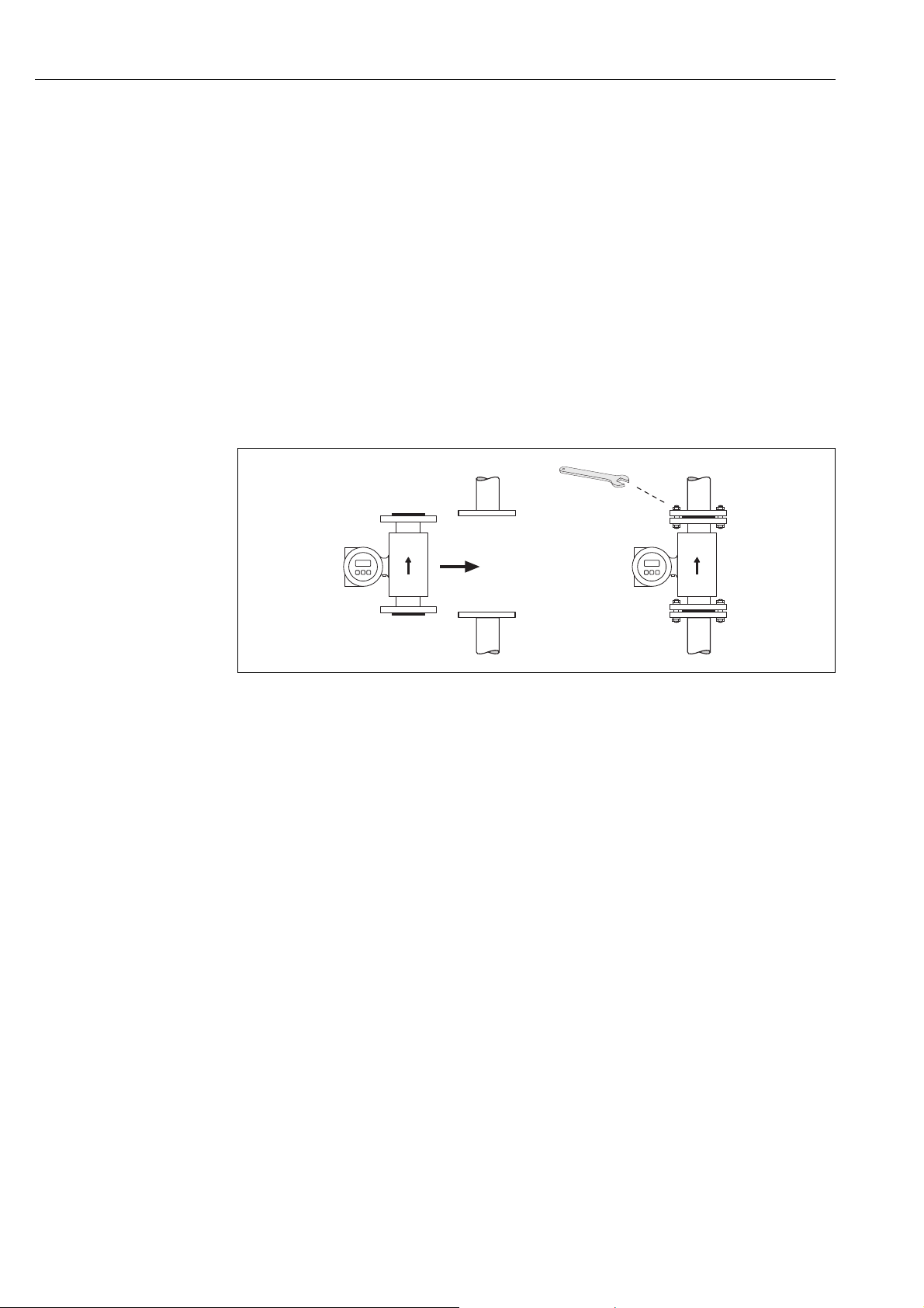
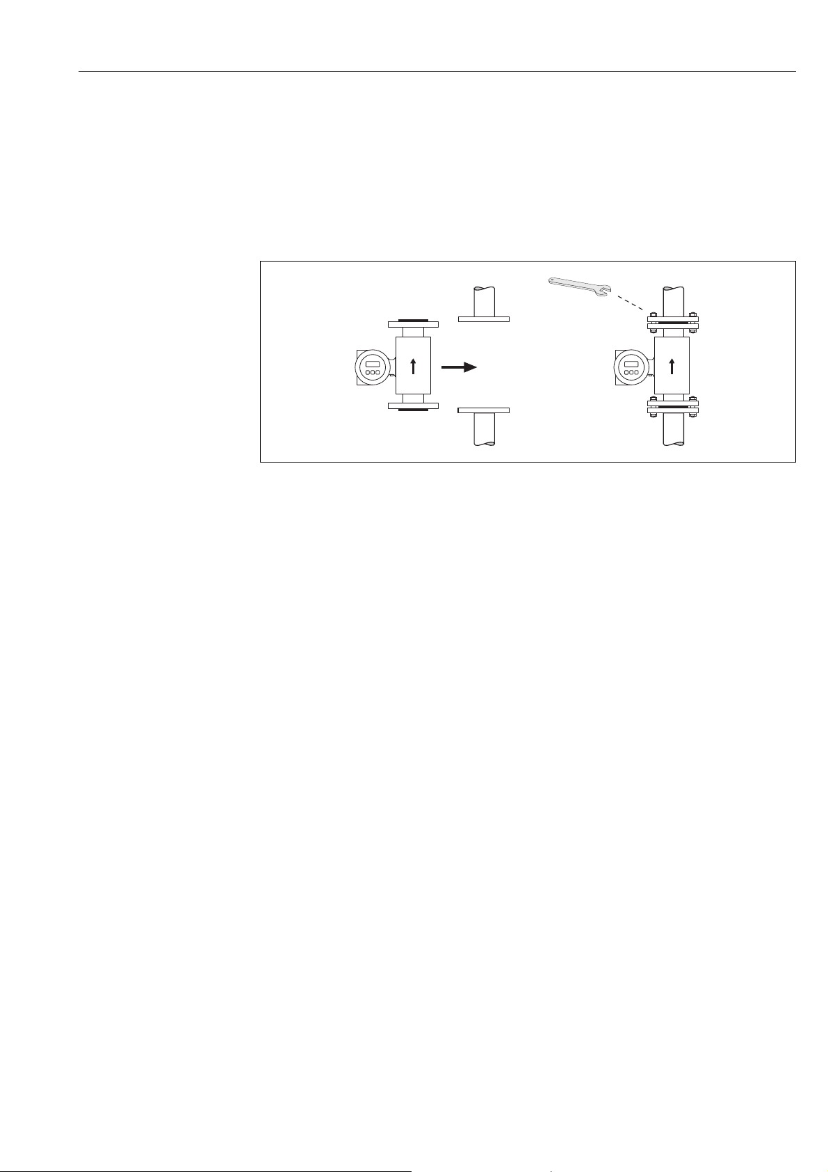
3.3.3 Installing the Promag W sensor
!
"
Note!
Bolts, nuts, seals, etc. are not included in the scope of supply and must be supplied by the customer.
The sensor is designed for installation between the two piping flanges.
• Observe in any case the necessary screw tightening torques on ä 27
• If grounding disks are used, follow the mounting instructions which will be enclosed with the
shipment
a0004296
Fig. 19: Installing the Promag W sensor
Seals
Comply with the following instructions when installing seals:
• Hard rubber lining additional seals are always necessary.
• Polyurethane lining no seals are required.
• For DIN flanges, use only seals according to EN 1514-1.
• Make sure that the seals do not protrude into the piping cross-section.
Caution!
Risk of short circuit!
Do not use electrically conductive sealing compounds such as graphite! An electrically conductive
layer could form on the inside of the measuring tube and short-circuit the measuring signal.
Ground cable
• If necessary, special ground cables for potential equalization can be ordered as an accessory
( ä 76).
• Information on potential equalization and detailed mounting instructions for the use of ground
cables can be found on ä 55
Screw tightening torques (Promag W)
Please note the following:
• The tightening torques listed below are for lubricated threads only.
• Always tighten the screws uniformly and in diagonally opposite sequence.
• Overtightening the screws will deform the sealing faces or damage the seals.
• The tightening torques listed below apply only to pipes not subjected to tensile stress.
Endress+Hauser 27

Installation Promag 50
Tightening torques for:
•EN (DIN) ä 28
• JIS ä 30
•ANSI ä 29
• AWWA ä 30
• AS 2129 ä 31
• AS 4087 ä 31
Promag W tightening torques for EN (DIN)
Nominal diameter EN (DIN)
[mm] Pressure rating [bar] Hard rubber Polyurethane
25 PN 40 4 × M 12 - 15
32 PN 40 4 × M 16 - 24
40 PN 40 4 × M 16 - 31
50 PN 40 4 × M 16 48 40
65* PN 16 8 × M 16 32 27
65 PN 40 8 × M 16 32 27
80 PN 16 8 × M 16 40 34
80 PN 40 8 × M 16 40 34
100 PN 16 8 × M 16 43 36
100 PN 40 8 × M 20 59 50
125 PN 16 8 × M 16 56 48
125 PN 40 8 × M 24 83 71
150 PN 16 8 × M 20 74 63
150 PN 40 8 × M 24 104 88
200 PN 10 8 × M 20 106 91
200 PN 16 12 × M 20 70 61
200 PN 25 12 × M 24 104 92
250 PN 10 12 × M 20 82 71
250 PN 16 12 × M 24 98 85
250 PN 25 12 × M 27 150 134
300 PN 10 12 × M 20 94 81
300 PN 16 12 × M 24 134 118
300 PN 25 16 × M 27 153 138
350 PN 6 12 × M 20 111 120
350 PN 10 16 × M 20 112 118
350 PN 16 16 × M 24 152 165
350 PN 25 16 × M 30 227 252
400 PN 6 16 × M 20 90 98
400 PN 10 16 × M 24 151 167
400 PN 16 16 × M 27 193 215
400 PN 25 16 × M 33 289 326
450 PN 6 16 × M 20 112 126
450 PN 10 20 × M 24 153 133
450 PN 16 20 × M 27 198 196
450 PN 25 20 × M 33 256 253
500 PN 6 20 × M 20 119 123
500 PN 10 20 × M 24 155 171
500 PN 16 20 × M 30 275 300
500 PN 25 20 × M 33 317 360
600 PN 6 20 × M 24 139 147
600 PN 10 20 × M 27 206 219
600 * PN 16 20 × M 33 415 443
600 PN 25 20 × M 36 431 516
700 PN 6 24 × M 24 148 139
700 PN 10 24 × M 27 246 246
700 PN 16 24 × M 33 278 318
Threaded
fasteners
Max. tightening torque [Nm]
28 Endress+Hauser

Promag 50 Installation
Nominal diameter EN (DIN)
[mm] Pressure rating [bar] Hard rubber Polyurethane
700 PN 25 24 × M 39 449 507
800 PN 6 24 × M 27 206 182
800 PN 10 24 × M 30 331 316
800 PN 16 24 × M 36 369 385
800 PN 25 24 × M 45 664 721
900 PN 6 24 × M 27 230 637
900 PN 10 28 × M 30 316 307
900 PN 16 28 × M 36 353 398
900 PN 25 28 × M 45 690 716
1000 PN 6 28 × M 27 218 208
1000 PN 10 28 × M 33 402 405
1000 PN 16 28 × M 39 502 518
1000 PN 25 28 × M 52 970 971
1200 PN 6 32 × M 30 319 299
1200 PN 10 32 × M 36 564 568
1200 PN 16 32 × M 45 701 753
1400 PN 6 36 × M 33 430 398
1400 PN 10 36 × M 39 654 618
1400 PN 16 36 × M 45 729 762
1600 PN 6 40 × M 33 440 417
1600 PN 10 40 × M 45 946 893
1600 PN 16 40 × M 52 1007 1100
1800 PN 6 44 × M 36 547 521
1800 PN 10 44 × M 45 961 895
1800 PN 16 44 × M 52 1108 1003
2000 PN 6 48 × M 39 629 605
2000 PN 10 48 × M 45 1047 1092
2000 PN 16 48 × M 56 1324 1261
* Designed acc. to EN 1092-1 (not to DIN 2501)
Threaded
fasteners
Max. tightening torque [Nm]
Promag W tightening torques for ANSI
Nominal
diameter
[mm] [inch] [Nm] [lbf · ft] [Nm] [lbf · ft]
25 1" Class 150 4 × ½" - - 7 5
25 1" Class 300 4 × 5/8" - - 8 6
40 1 ½" Class 150 4 × ½" - - 10 7
40 1 ½" Class 300 4 × ¾" - - 15 11
50 2" Class 150 4 × 5/8" 35 26 22 16
50 2" Class 300 8 × 5/8" 18 13 11 8
80 3" Class 150 4 × 5/8" 60 44 43 32
80 3" Class 300 8 × ¾" 38 28 26 19
100 4" Class 150 8 × 5/8" 42 31 31 23
100 4" Class 300 8 × ¾" 58 43 40 30
150 6" Class 150 8 × ¾" 79 58 59 44
150 6" Class 300 12 × ¾" 70 52 51 38
200 8" Class 150 8 × ¾" 107 79 80 59
250 10" Class 150 12 × 7/8" 101 74 75 55
300 12" Class 150 12 × 7/8" 133 98 103 76
350 14" Class 150 12 × 1" 135 100 158 117
400 16" Class 150 16 × 1" 128 94 150 111
450 18" Class 150 16 × 1 1/8" 204 150 234 173
500 20" Class 150 20 × 1 1/8" 183 135 217 160
600 24" Class 150 20 × 1 ¼" 268 198 307 226
ANSI Max. tightening torque
Pressure rating
[lbs]
Threaded
fasteners
Hard rubber Polyurethane
Endress+Hauser 29

Installation Promag 50
Promag W tightening torques for JIS
Nominal diameter JIS Threaded
[mm] Pressure rating Hard rubber Polyurethane
25 10K 4 × M 16 - 19
25 20K 4 × M 16 - 19
32 10K 4 × M 16 - 22
32 20K 4 × M 16 - 22
40 10K 4 × M 16 - 24
40 20K 4 × M 16 - 24
50 10K 4 × M 16 40 33
50 20K 8 × M 16 20 17
65 10K 4 × M 16 55 45
65 20K 8 × M 16 28 23
80 10K 8 × M 16 29 23
80 20K 8 × M 20 42 35
100 10K 8 × M 16 35 29
100 20K 8 × M 20 56 48
125 10K 8 × M 20 60 51
125 20K 8 × M 22 91 79
150 10K 8 × M 20 75 63
150 20K 12 × M 22 81 72
200 10K 12 × M 20 61 52
200 20K 12 × M 22 91 80
250 10K 12 × M 22 100 87
250 20K 12 × M 24 159 144
300 10K 16 × M 22 74 63
300 20K 16 × M 24 138 124
fasteners
Max. tightening torque [Nm]
Promag W tightening torques for AWWA
Nominal diameter AWWA Max. tightening torque
Pressure
[mm] [inch] [Nm] [lbf · ft] [Nm] [lbf · ft]
700 28" Class D 28 × 1 ¼" 247 182 292 215
750 30" Class D 28 × 1 ¼" 287 212 302 223
800 32" Class D 28 × 1 ½" 394 291 422 311
900 36" Class D 32 × 1 ½" 419 309 430 317
1000 40" Class D 36 × 1 ½" 420 310 477 352
1050 42" Class D 36 × 1 ½" 528 389 518 382
1200 48" Class D 44 × 1 ½" 552 407 531 392
1350 54" Class D 44 × 1 ¾" 730 538 633 467
1500 60" Class D 52 × 1 ¾" 758 559 832 614
1650 66" Class D 52 × 1 ¾" 946 698 955 704
1800 72" Class D 60 × 1 ¾" 975 719 1087 802
2000 78" Class D 64 × 2" 853 629 786 580
rating
Threaded
fasteners
Hard rubber Polyurethane
30 Endress+Hauser
 Loading...