

Page 1
BA00424G/00/EN/17.18
71424923
Valid as of software version:
02.02.00
Products Solutions Services
Operating Instructions
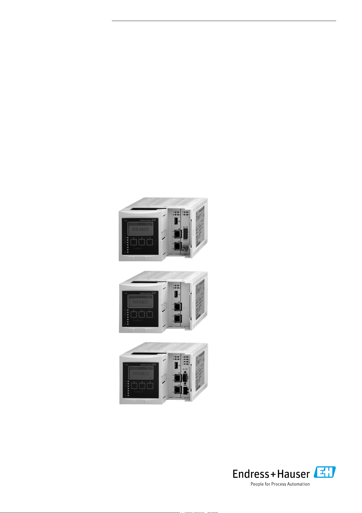
Tankvision
Tank Scanner NXA820,
Data Concentrator NXA821,
Host Link NXA822
Operator Manual
Page 2
Tankvision
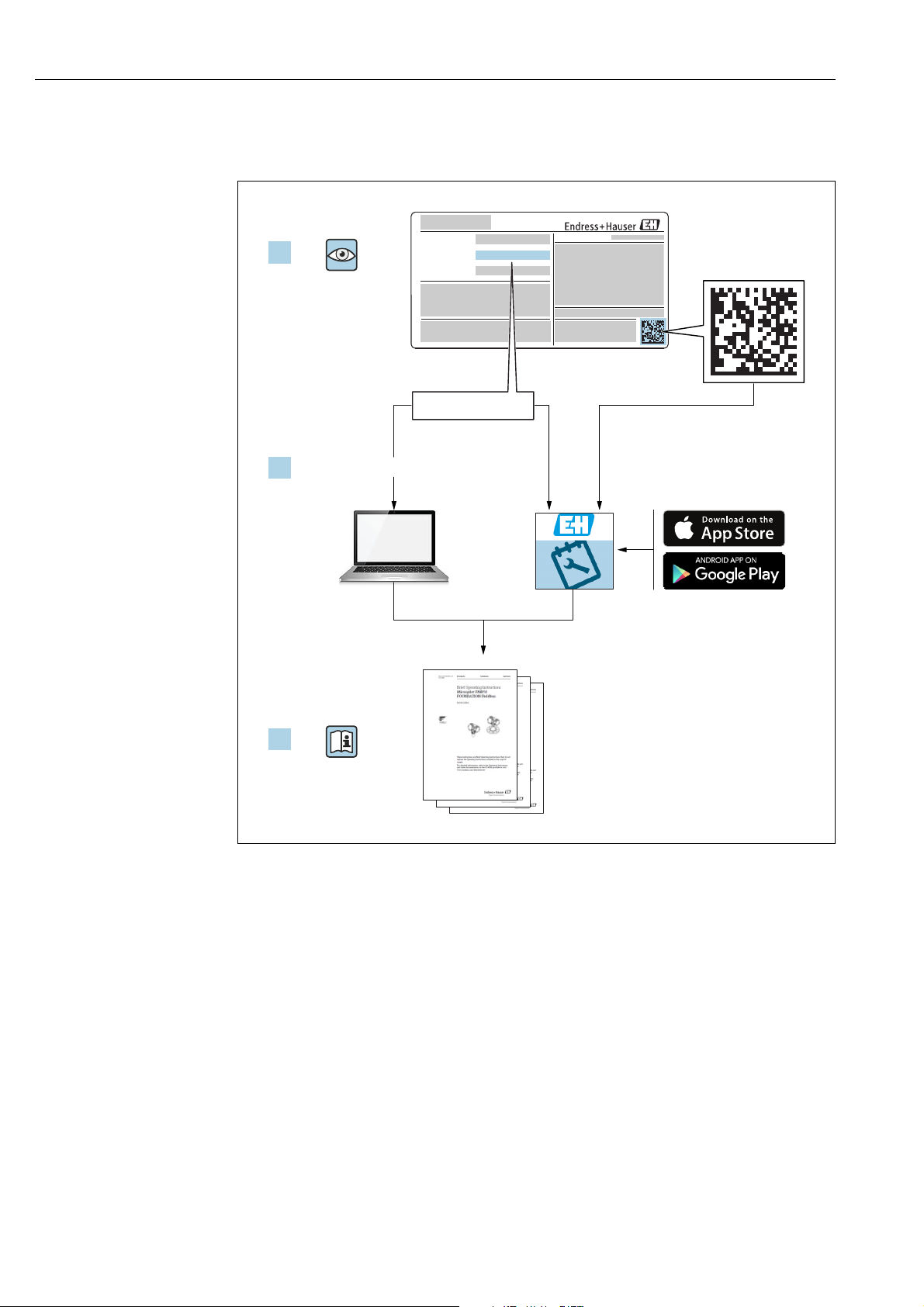
Order code:
Ext. ord. cd.:
Ser. no.:
www.endress.com/deviceviewer
Endress+Hauser
Operations App
XXXXXXXXXXXX
XXXXX-XXXXXX
XXX.XXXX.XX
Serial number
1.
3.
2.
Make sure the document is stored in a safe place such that it is always available when
working on or with the device.
To avoid danger to individuals or the facility, read the "Basic safety instructions" section
carefully, as well as all other safety instructions in the document that are specific to
working procedures.
The manufacturer reserves the right to modify technical data without prior notice. Your
Endress+Hauser distributor will supply you with current information and updates to
these Instructions.
A0023555
2 Endress+Hauser
Page 3

Tankvision
Table of Contents
1 Document information . . . . . . . . . . . . . . 4
1.1 Document function . . . . . . . . . . . . . . . . . . . . . . . . . . 4
1.2 Symbols . . . . . . . . . . . . . . . . . . . . . . . . . . . . . . . . . . . 4
1.3 Documentation . . . . . . . . . . . . . . . . . . . . . . . . . . . . . 6
1.4 Registered trademarks . . . . . . . . . . . . . . . . . . . . . . . 6
2 Basic safety instructions . . . . . . . . . . . . . 7
2.1 Requirements for the personnel . . . . . . . . . . . . . . . 7
2.2 Designated use . . . . . . . . . . . . . . . . . . . . . . . . . . . . . 7
2.3 Workplace safety . . . . . . . . . . . . . . . . . . . . . . . . . . . 8
2.4 Operational safety . . . . . . . . . . . . . . . . . . . . . . . . . . . 8
2.5 Product safety . . . . . . . . . . . . . . . . . . . . . . . . . . . . . . 8
2.6 IT security . . . . . . . . . . . . . . . . . . . . . . . . . . . . . . . . . . 8
3 Recommendation PC configuration. . . . 9
4 User interface . . . . . . . . . . . . . . . . . . . . .10
5 User access rights. . . . . . . . . . . . . . . . . . 13
6 Operations. . . . . . . . . . . . . . . . . . . . . . . . 15
6.1 How to log on? . . . . . . . . . . . . . . . . . . . . . . . . . . . . 15
6.2 How to view tank details . . . . . . . . . . . . . . . . . . . 17
6.3 How to view Temperature Profiles . . . . . . . . . . . 25
6.4 How to view Density Profiles . . . . . . . . . . . . . . . . 26
6.5 How to view and enter Manual Data . . . . . . . . . 27
6.6 How to enter dipped data . . . . . . . . . . . . . . . . . . . 29
6.7 How to issue gauge commands . . . . . . . . . . . . . . 29
6.8 How to view a real time trend . . . . . . . . . . . . . . . 34
6.9 How to assign/change products at a tank . . . . . 37
6.10 How to do Product transfer . . . . . . . . . . . . . . . . . 38
6.11 How to view a Transfer report . . . . . . . . . . . . . . . 44
6.12 How to view and change Tank Status . . . . . . . . . 45
6.13 How to do tank calculations . . . . . . . . . . . . . . . . . 48
6.14 How to view products groups . . . . . . . . . . . . . . . 49
6.15 How to view customized groups . . . . . . . . . . . . . 52
6.16 How to view transfer groups . . . . . . . . . . . . . . . . 55
6.17 How to issue reports . . . . . . . . . . . . . . . . . . . . . . . 56
6.18 How to view and acknowledge alarms . . . . . . . . 63
6.19 How to select and view historical trends . . . . . . 70
6.20 How to check the sealing status . . . . . . . . . . . . . 72
7 Diagnostics and troubleshooting. . . . . 75
7.1 General troubleshooting . . . . . . . . . . . . . . . . . . . 75
7.2 Firmware history . . . . . . . . . . . . . . . . . . . . . . . . . . 75
8 Maintenance. . . . . . . . . . . . . . . . . . . . . . 76
9 Repair. . . . . . . . . . . . . . . . . . . . . . . . . . . . 76
Index. . . . . . . . . . . . . . . . . . . . . . . . . . . . . 77
Endress+Hauser 3
Page 4
Document information Tankvision
DANGER
WARNING
CAUTION
NOTICE
1 Document information
1.1 Document function
This manual should support the operating personal working on a regular basis with the Tank
Gauging System understanding the possible tasks they have to perform and should serve as
encyclopedia for those tasks.
Beside basic PC operating knowledge no special training is needed to perform the Tank
Gauging System operations. Nevertheless it is recommended receiving a training on the
system by Endress+Hauser.
1.2 Symbols
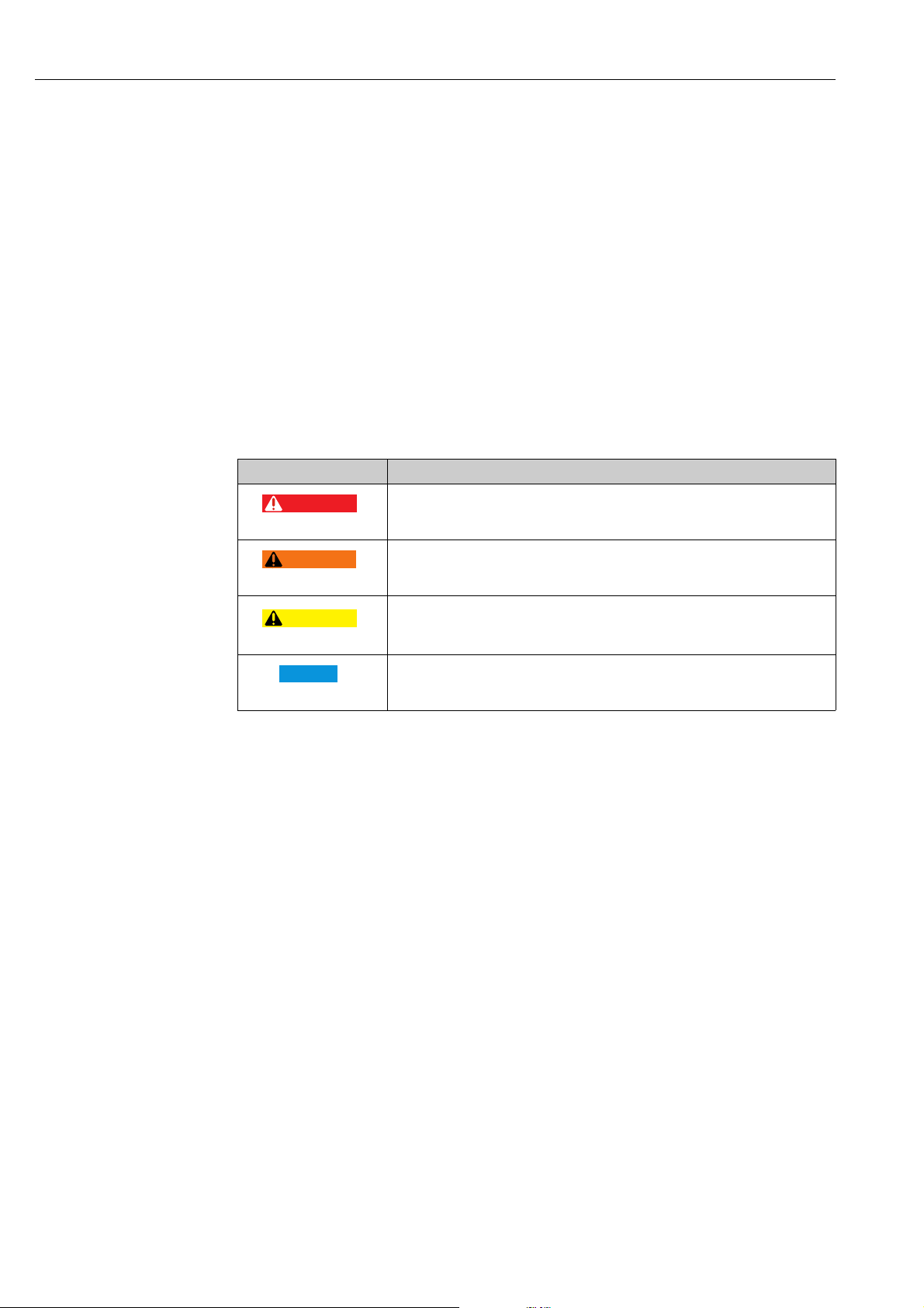
1.2.1 Safety symbols
Symbol Meaning
DANGER!
A0011189-EN
A0011190-EN
A0011191-EN
A0011192-EN
This symbol alerts you to a dangerous situation. Failure to avoid this situation will
result in serious or fatal injury.
WARNING!
This symbol alerts you to a dangerous situation. Failure to avoid this situation can
result in serious or fatal injury.
CAUTION!
This symbol alerts you to a dangerous situation. Failure to avoid this situation can
result in minor or medium injury.
NOTICE!
This symbol contains information on procedures and other facts which do not result
in personal injury.
4 Endress+Hauser
Page 5
Tankvision Document information
)
*
1.
2.
3.
1.
2.
3.
-
.
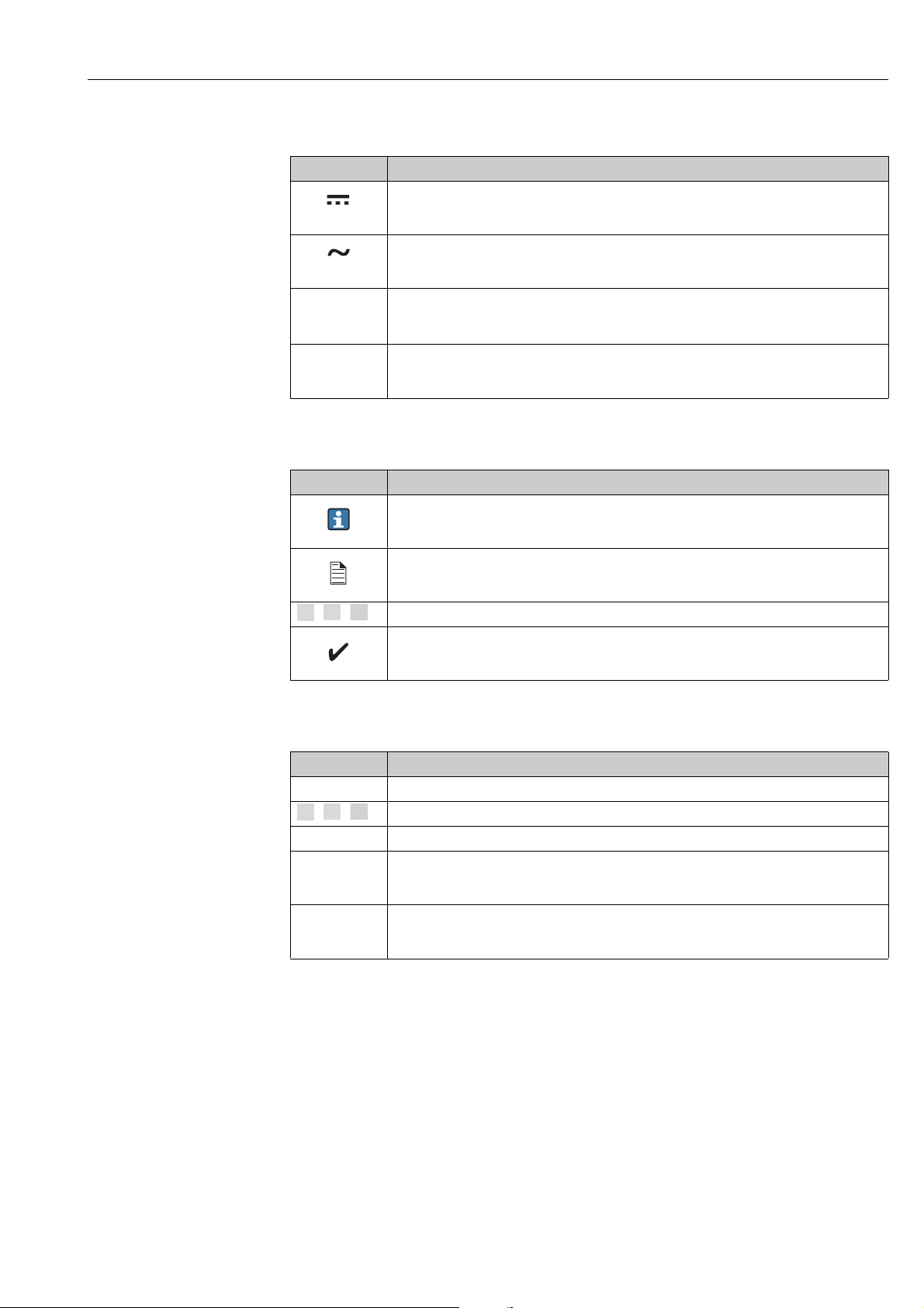
1.2.2 Electrical symbols
Symbol Meaning
Direct current
A terminal to which DC voltage is applied or through which direct current flows.
A0011197
Alternating current
A terminal to which alternating voltage is applied or through which alternating current flows.
A0011198
Ground connection
A grounded terminal which, as far as the operator is concerned, is grounded via a grounding
A0011200
system.
Protective ground connection
A terminal which must be connected to ground prior to establishing any other connections.
A0011199
1.2.3 Symbols for certain types of information
Symbol Meaning
Tip
Indicates additional information.
A0011193
Reference to page
Refers to the corresponding page number.
A0011195
, , ... Series of steps.
Result of a sequence of actions.
A0018373
1.2.4 Symbols in graphics
Symbol Meaning
1, 2, 3 ... Item numbers
, , ... Series of steps
A, B, C ... Views
Hazardous area
Indicates a hazardous area.
A0011187
Indicates a non-hazardous location
Safe area (non-hazardous area)
A0011188
Endress+Hauser 5
Page 6

Document information Tankvision
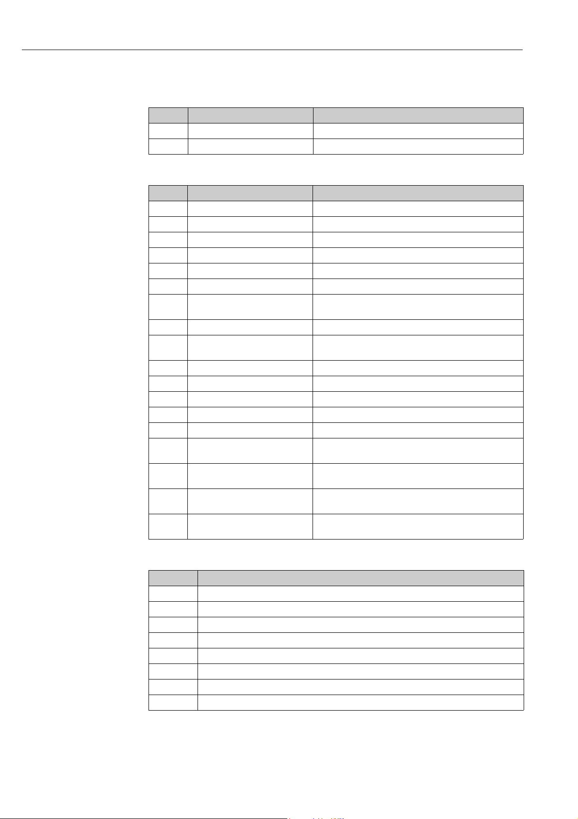
1.3 Documentation
1.3.1 Operating instructions
Document number Instrument Type of Document
BA00339G/00
BA00340G/00 Installation Instructions
BA00424G/00 System Description
BA00426G/00 Operator Manual
BA01137G/00 Tankvision NXA820 OPC Server User Manual
• Tank Scanner NXA820
• Data Concentrator NXA821
• Host Link NXA822
Description of Instrument Functions
1.4 Registered trademarks
Microsoft®, Windows® and Internet Explorer
Registered trademarks of the Microsoft Corporation
®
Modbus
TM
Modbus is a registered trademark of Schneider Electric USA, Inc.
®
Java
Registered trademark of Oracle® Corporation
Mozilla
®
Firefox
®
Registered trademark of the Mozilla Foundation
6 Endress+Hauser
Page 7

Tankvision Basic safety instructions
2 Basic safety instructions
2.1 Requirements for the personnel
The personnel for installation, commissioning, diagnostics and maintenance must fulfill the
following requirements:
• Trained, qualified specialists: must have a relevant qualification for this specific function
and task
• Are authorized by the plant owner/operator
• Are familiar with federal/national regulations
• Before beginning work, the specialist staff must have read and understood the instructions
in the Operating Instructions and supplementary documentation as well as in the
certificates (depending on the application)
• Following instructions and basic conditions
The operating personnel must fulfill the following requirements:
• Being instructed and authorized according to the requirements of the task by the facility's
owner operator
• Following the instructions in these Operating Instructions
2.2 Designated use
2.2.1 Application
Tankvision is a dedicated tank inventory management system.
Components:
• Tankvision Tank Scanner NXA820
scans parameters from tank gauges and performs tank calculations
• Tankvision Data Concentrator NXA821
summarizes data from various Tank Scanners NXA820
• Tankvision Host Link NXA822
provides data to host systems (such as PLC or DCS) via Modbus
The above mentioned components are operated via a standard web browser. It does not
require any proprietary software. Tankvision is based on a distributed architecture on a Local
Area Network (LAN). Due to its modular structure it can be adjusted to any application. It is
ideally suited for small tank farms with only a couple of tanks, but also for large refineries
with hundreds of tanks.
Endress+Hauser 7
Page 8

Basic safety instructions Tankvision
2.3 Workplace safety
For work on and with the device:
• Wear the required personal protective equipment according to federal/national
regulations.
• Switch off the supply voltage before connecting the device.
2.4 Operational safety
Risk of injury!
• Operate the device in proper technical condition and fail-safe condition only.
• The operator is responsible for interference-free operation of the device.
Conversions to the device
Unauthorized modifications to the device are not permitted and can lead to unforeseeable
dangers
• If, despite this, modifications are required, consult with Endress+Hauser.
Repair
To ensure continued operational safety and reliability,
• Carry out repairs on the device only if they are expressly permitted.
• Observe federal/national regulations pertaining to repair of an electrical device.
• Use original spare parts and accessories from Endress+Hauser only.
2.5 Product safety
The device is designed to meet state-of-the-art safety requirements, has been tested and left
the factory in a condition in which it is safe to operate. The device complies with the
applicable standards and regulations as listed in the EC declaration of conformity and thus
complies with the statutory requirements of the EG directives. Endress+Hauser confirms the
successful testing of the device by affixing to it the CE mark.
2.6 IT security
We only provide a warranty if the device is installed and used as described in the Operating
Instructions. The device is equipped with security mechanisms to protect it against any
inadvertent changes to the device settings.
IT security measures in line with operators' security standards and designed to provide
additional protection for the device and device data transfer must be implemented by the
operators themselves.
Endress+Hauser can be contacted to provide support in performing this task.
8 Endress+Hauser
Page 9

Tankvision Recommendation PC configuration
3 Recommendation PC configuration
With all on the market available web browser entering the Tankvision web server is possible.
Nevertheless the pages are optimized for Microsoft Internet Explorer (supported version IE9,
IE10 and IE11– Compatibility Mode).
The user interface pages are optimized for a screen resolution of 1280x1024 (or higher).
Endress+Hauser 9
Page 10
User interface Tankvision
1
2
34
65
4 User interface
Tankvision provides an intuitive user interface allowing the user to quickly navigate through
the system. The following sections illustrate various parts of the Tankvision user interface
and their usage.
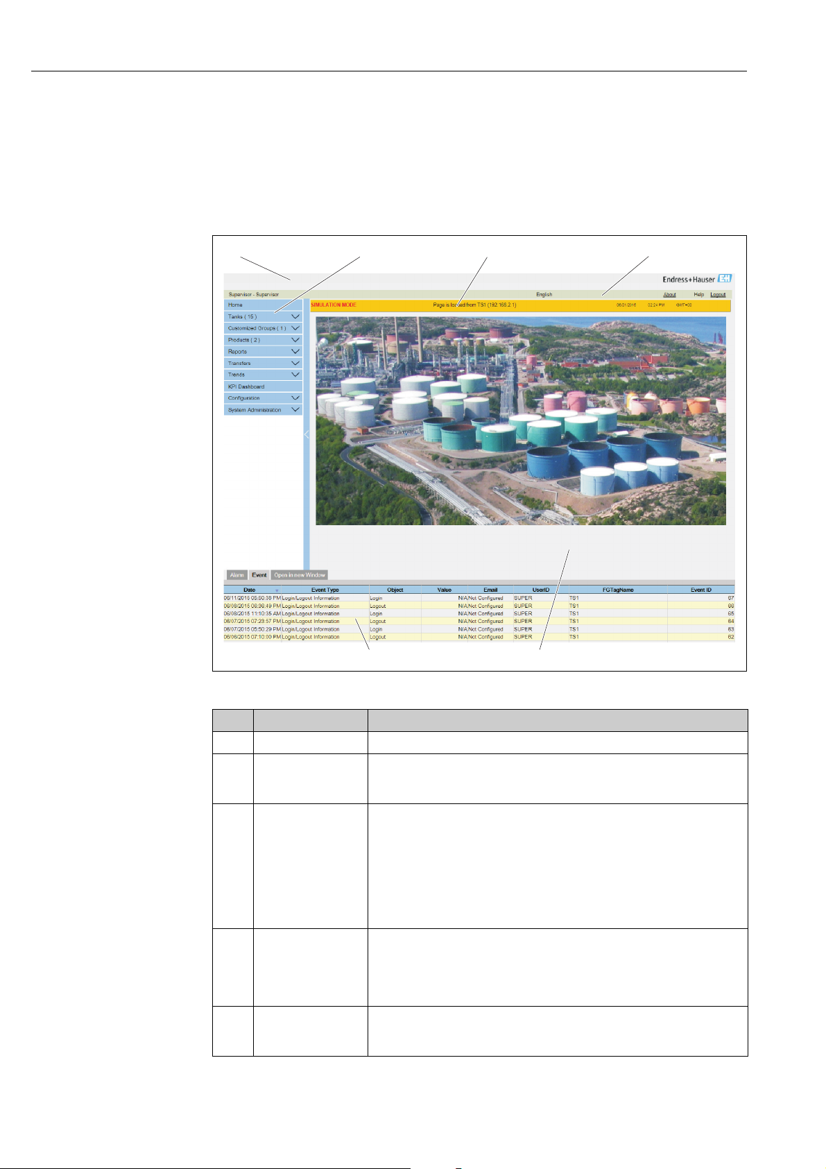
The Home Page
The_Homepage
Pos. Field Description
1 System Header Displays the Customer Logo or Graphic.
2 Navigation Tree Contains header bars corresponding to different functional objects or groups in
3 Main Header Displays the following information:
4 Metadata Header Displays the following information:
5 Main View Displays the screens that the user has selected to configure the settings and
the system.
Refer to "Navigation Tree - detailed description" (→ ä 11) for details.
• The site name, tank name, Tankvision tag name or product name depending on what is displayed in the Main View below the header
• The system date and time
The main header is displayed with a background color depending on the access
rights of the user logged into the system:
• Grey: the user does not have configuration rights and can only view data.
• Orange: the user has configuration rights and can view real time data.
• The user name and the user type
• The language options link
• The help link
• The logout option
view the operational information. Refer to "Main View Section- Colors in Edit
Data" (→ ä 12) for details.
10 Endress+Hauser
Page 11
Tankvision User interface
1
2
3
5
4
Pos. Field Description
6Alarm and Event
Panel
The Alarm and Event Panel displays the real time information about alarms
and events.
Refer to "Alarm and Event Panel Section- Description" (→ ä 12) for details.
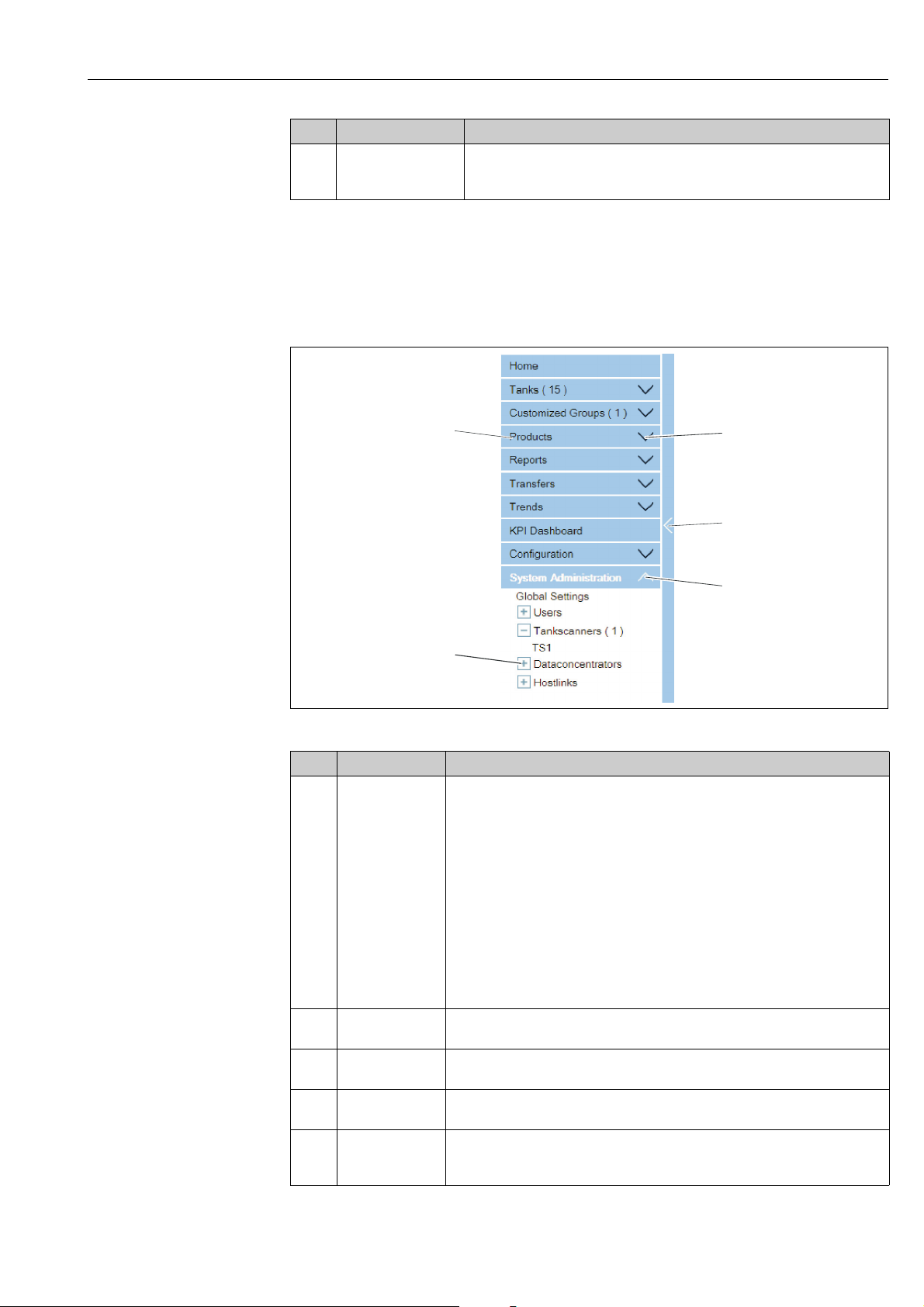
Navigation Tree - Detailed Description
The Navigation Tree is shown on the left side of the screen. Typically, the Navigation Tree
allows the user to navigate down to the tanks. The image of the expanded Navigation Tree
is as follows:
Navigation_Tree _Detailed_EN
Pos. Field Description
1 Header The user can click on the text or the arrow of the Header to expand or collapse the
branch.
The Header name shows a number, which is dynamically appended. The number
states the following:
• Tanks: The number of tanks in the NXA820
• Products: The number of products defined in the system
• Customized Groups: The number of tank groups defined in the system
• Transfers: The number of product transfer stages (Waiting, In Progress,
Finished, and Aborted) defined in the system
• Reports: The list of available system reports
• Users: The number of users defined in the system
• Historical Trend: Direct line to the historical Historical Data and Trend
functionality
The text will appear in bold and black when the header is in the expanded form.
2 Collapsed Arrow This type of arrow is displayed when the Header is in the collapsed position. Click
3Collapse/Expand
Navigation Tree
4 Expanded Arrow This type of arrow is displayed when the Header is in the expanded position. Click
5 Node The user can click on the Node to view the operational information on the Main
on the collapsed arrow to expand the Header.
The user can click on this arrow to collapse or expand the Navigation Tree.
on the expanded arrow to collapse the Header.
View section. If a Node is selected, it will appear in red color.
The number of tanks in the group is appended to the Node name.
Endress+Hauser 11
Page 12
User interface Tankvision
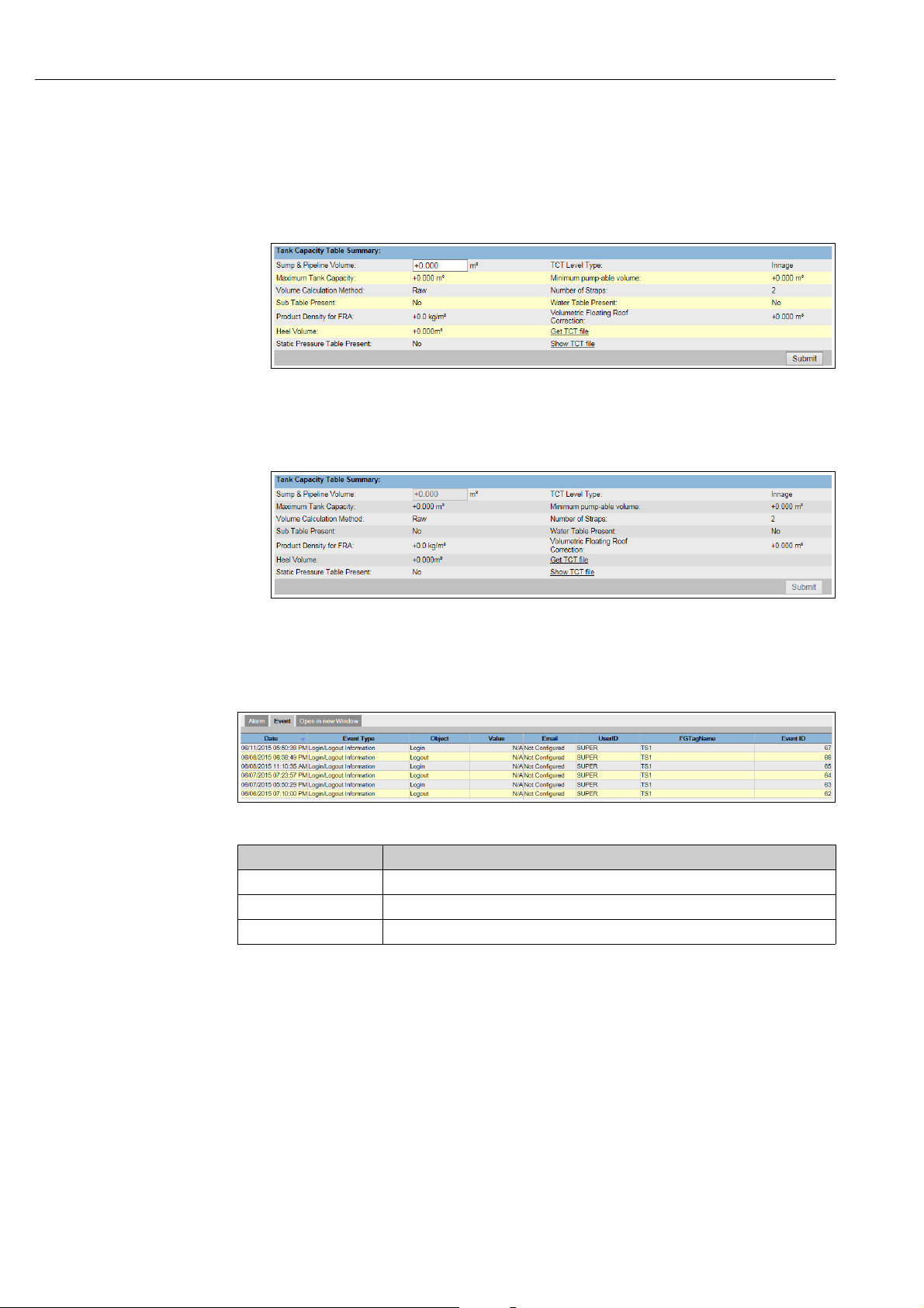
Main View Section - Colors in the Edit Data Area
The system displays different colors in the Edit Data area, based on the access rights of the
user:
1. If the user has access rights, then the edit data area has a light grey and light yellow
background on alternate rows. The Submit button to save the settings is enabled.
NXA82x_Tank-Capacity-Table-Summary
2. If the user does not have access rights, then the edit data area has a light grey and dark
grey background on alternate rows. The Submit button to save the settings is disabled.
NXA82x_Tank-Capacity-Table-Summary_Inactive
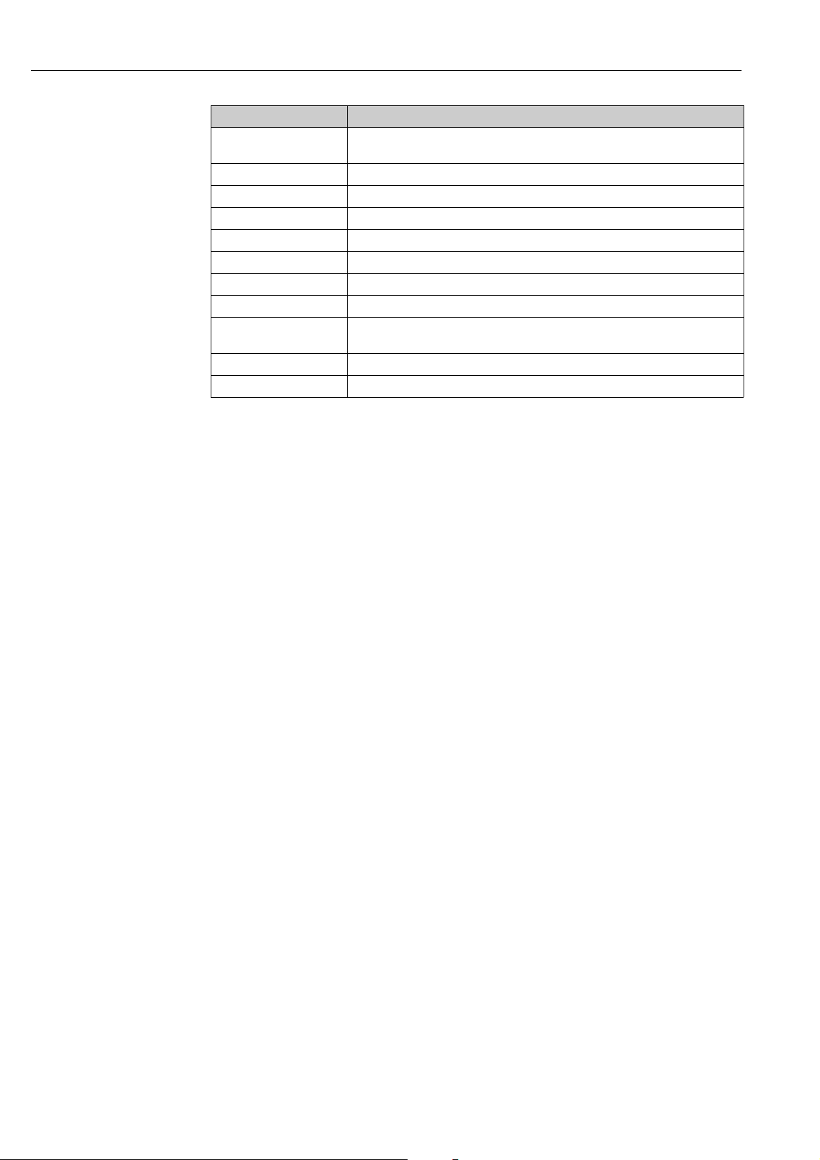
Alarm and Event Panel - Description
The Alarm and Event Panel displays the alarm and event information, which is dynamically
generated by the system. 200 events are shown.
Events (Overview)
Tab Description
Alarm Displays details of the alarms generated by the system.
Events Displays details of the events generated by the system.
Open in new Window Opens the Alarm and Event Panel in a new window.
12 Endress+Hauser
Page 13
Tankvision User access rights
5 User access rights
The Tankvision system has an inbuilt authentication mechanism to prevent unauthorized
access. The system identifies the user by a unique logon name and password. The system
records all the activities performed by each user and allows only a specific number of users
from each user type to be logged in at the same time. This can be configured in system
settings by an authorized entity. Each Tankvision unit has an option to confine user access
rights data for local use within the unit or enable user access rights data for the central
Tankvision unit thereby allowing the user to access all the units that are configured to the
central Tankvision unit.
All in this manual described functionality is based on the default settings for the role
of the "Operator". The operator is not allowed to perform any changes in the user access
rights.
In case the "Operator" is allowed to perform other operations than the ones specified
with the default settings refer to the "Description of Instrument Functions" BA00339F/00/EN.
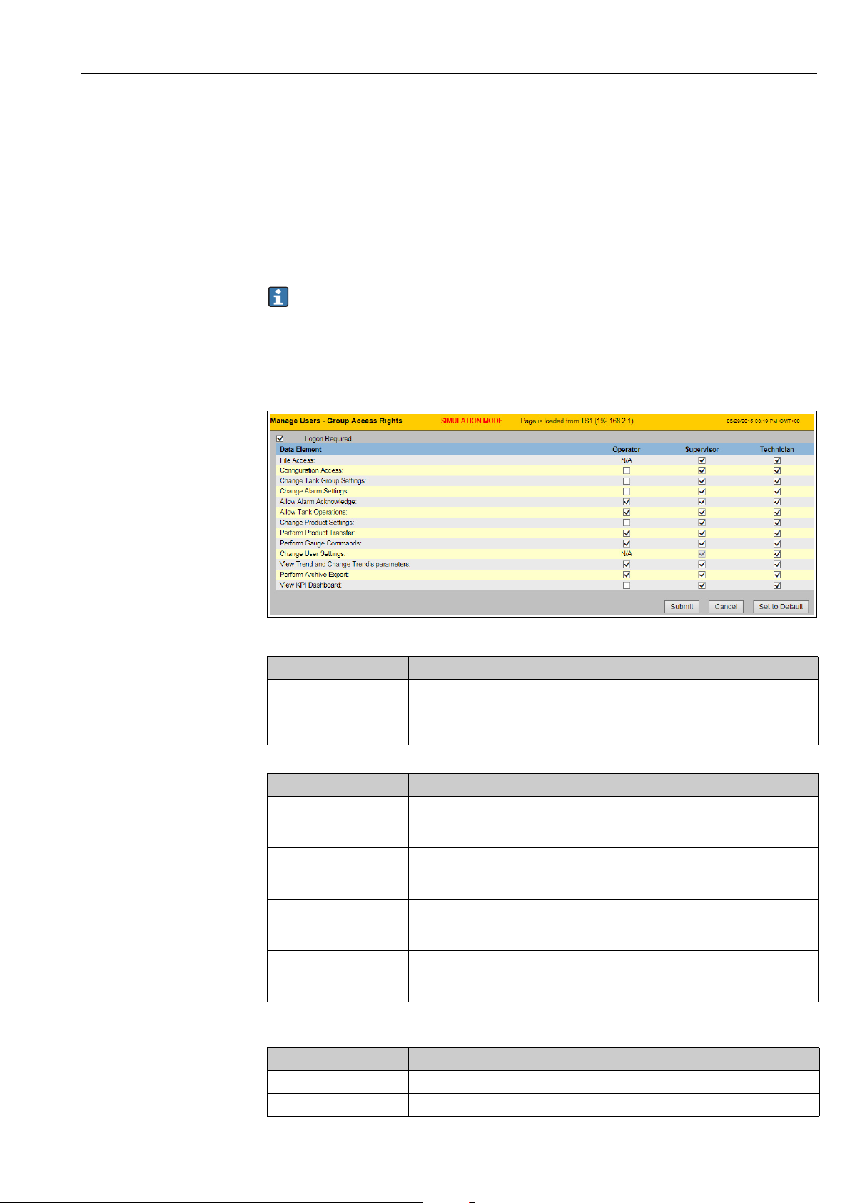
NXA82x_Manage-User-Group-Access -Rights
Field Description
Logon Required Select the check box to prompt the user to log on to access the Tankvision system.
Clear the check box to allow the user to access any feature of the Tankvision system
without logging in to the system. This Field indicates whether the user needs to
logon to the system to access the Tankvision functionality.
Column Description
Data Element This column displays a list of Data Elements, which are accessible only to specific
Operator An operator performs day-to-day operations at the tank farm and can view
Supervisor A supervisor configures and maintains the Tankvision system. He can view
Technician A technician is a service person from Endress+Hauser who performs the initial
user groups. To obtain access to these elements, the user with valid access rights
(for example, supervisor/ technician) needs to allot access rights to the user group.
refreshed data and alarm notifications. Select the appropriate check box to allow
the operator group to access the relevant Data Element.
refreshed data and alarm notifications. Select the appropriate check box to allow
the supervisor group to access the relevant Data Element.
setup and configuration of the Tankvision system. Select the appropriate check box
to allow the technician group to access a particular Data Element.
Data Elements Description
File Access Access to allow file upload or download e.g. Firmware or web page templates
Configuration Access Access to change configuration
Endress+Hauser 13
Page 14
User access rights Tankvision
Data Elements Description
Change Tank Group
Settings
Change Alarm Settings Allows to create, modify and delete alarm configurations
Allow Alarm Acknowledge Allows to acknowledge active alarms
Allow Tank Operations Allows to change tank status, product contents and enter manual data operations
Change Product Settings Allows to create, modify and delete products
Perform Product Transfer Allows to arm, start and stop product movements
Perform Gauge Commands Allows to issue, kill and schedule gauge commands
Change User Settings Allows to add, modify and delete users, and modify user access rights
View Trend and Change
Trend’s parameters
Perform Archive Export Allows the export of the archive.
View KPI Dashboard Allows to view the KPI Dashboard.
Allows to add, modify and delete tank group settings for static and dynamic tank
groups
Allows to configure real time and historical trend, and start or stop the real time
and historical trends
14 Endress+Hauser
Page 15
Tankvision Operations
1.
2.
3.
6Operations
6.1 How to log on?
The below described operations can be performed with the default user access rights for an
operator ("User access rights", → ä 13).
The user interface is reached via standard web browsers whereas the recommended web
browser is Microsoft Internet Explorer.
Open a browser window (depending on the PC configuration this point might be skipped
as opening a browser window is configured to be in the auto start and can’t be closed
without the necessary PC access rights.
Type in the IP address
IP addresses are specific for every single Tankvision units in the system (example IP
address 192.168.2.1). Depending on the browser configuration this point might be
skipped as it is recommended to select the Tankvision IP address as home page which is
automatically opened the browser starts up.
The user interface opens and is ready for operation. Per default Tankvision is delivered
without a logon required. In this case the default user access rights are set to Operator.
The following screens opens:
Endress+Hauser 15
Page 16
Operations Tankvision
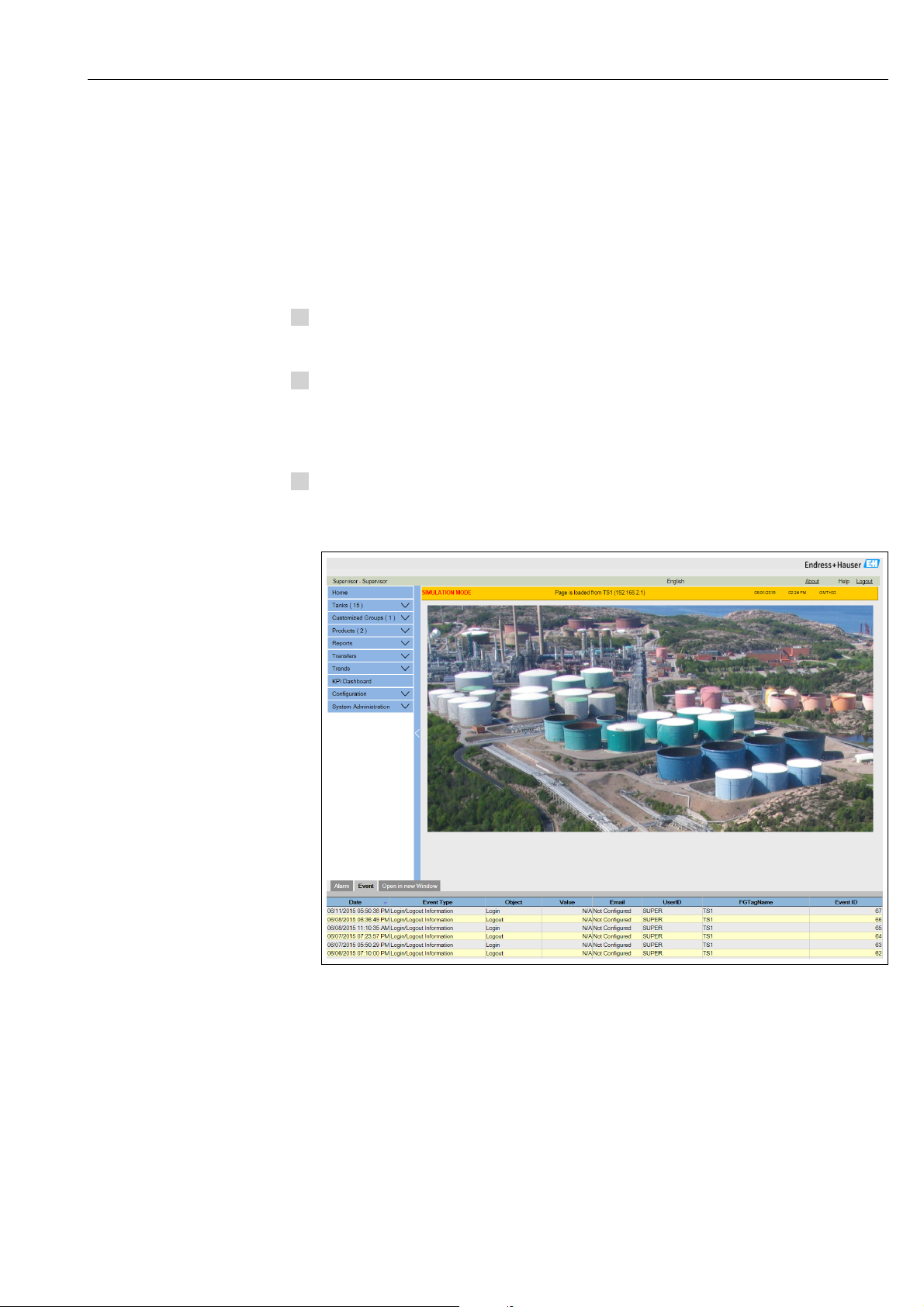
If Logon required is selected in the user access rights (done during commissioning by the
supervisor) the following screen opens before the above:
NXA82x_Login-Screen
Field Description
User ID Enter the appropriate user login name .
The user login name is alphanumeric and case sensitive.
Password Enter the appropriate password.
The user password is alphanumeric and case sensitive. It consists of 3 to 8
characters.
User ID and the according Password are created during commissioning. Factory default:
•User ID: Oper
• Password: Oper
16 Endress+Hauser
Page 17
Tankvision Operations
1.
6.2 How to view tank details
The below described operations can be performed with the default user access rights for an
operator ("User access rights", → ä 13).
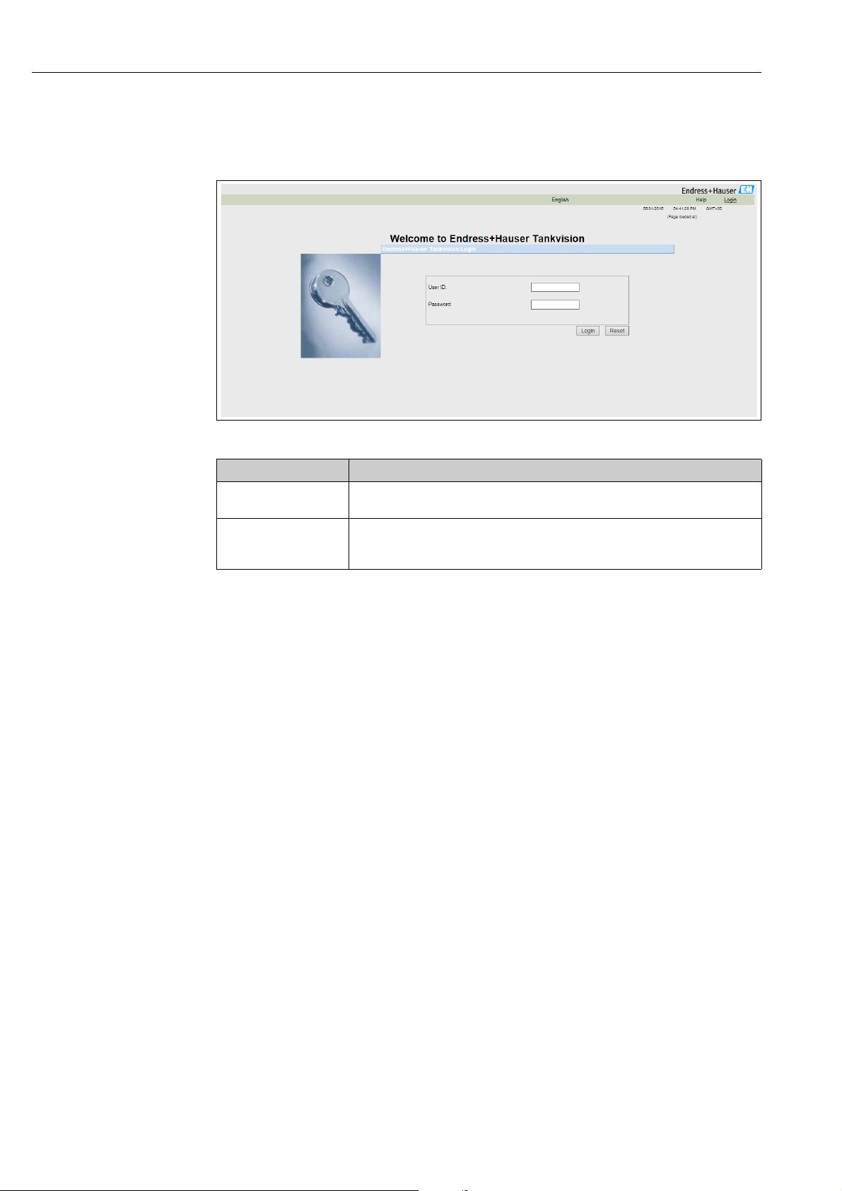
The General Details tab displays the most important tank data dynamically.
To view the General Details tab
On the Tank Details screen, click the Tank Details tab. Tankvision displays the screen
as follows:
NXA82x_Tank_ General-Details-Tab
Column Description
Tank Overview This area displays the picture of the tank.
Alarm Set Points This area displays the corresponding Alarm Set Points for that particular tank.
Main Values This area displays the measured and calculated values of the product or tank parameters
in terms of temperature, pressure, density and water level along with their respective
units of measurement, depending on the configuration made in Tank Details View
Configuration (see BA00339G). The date and time at which the value of each parameter
has changed is also displayed along with the measured value status:
•OK
Ok Status
•INIT
Field Scan started, value not yet received and processed
•MANUAL
Value set to manual
• NODATA
Calculation not configured, Field Scan is off
• INVALIDDATA
Calculation is out of boundaries
• LASTVALIDVALUE
Value is set on HOLD, need additional servo configuration
•FAIL
Communication error on field protocol of device configuration
• NOT CALIBRATED
Value is not calibrated
Endress+Hauser 17
Page 18

Operations Tankvision
Column Description
Secondary Values This area displays the measured and calculated values of the product parameters in terms
of volume, tank capacity, reference density, floating roof adjustment, product and vapor
mass along with their respective units of measurement and status. Which values are
displayed, depends on the configuration made in Tank Details View Configuration (see
BA00339G).
Tank & Product
Configuration
This area displays the tank and product configuration data used for calculation.
18 Endress+Hauser
Page 19
Tankvision Operations
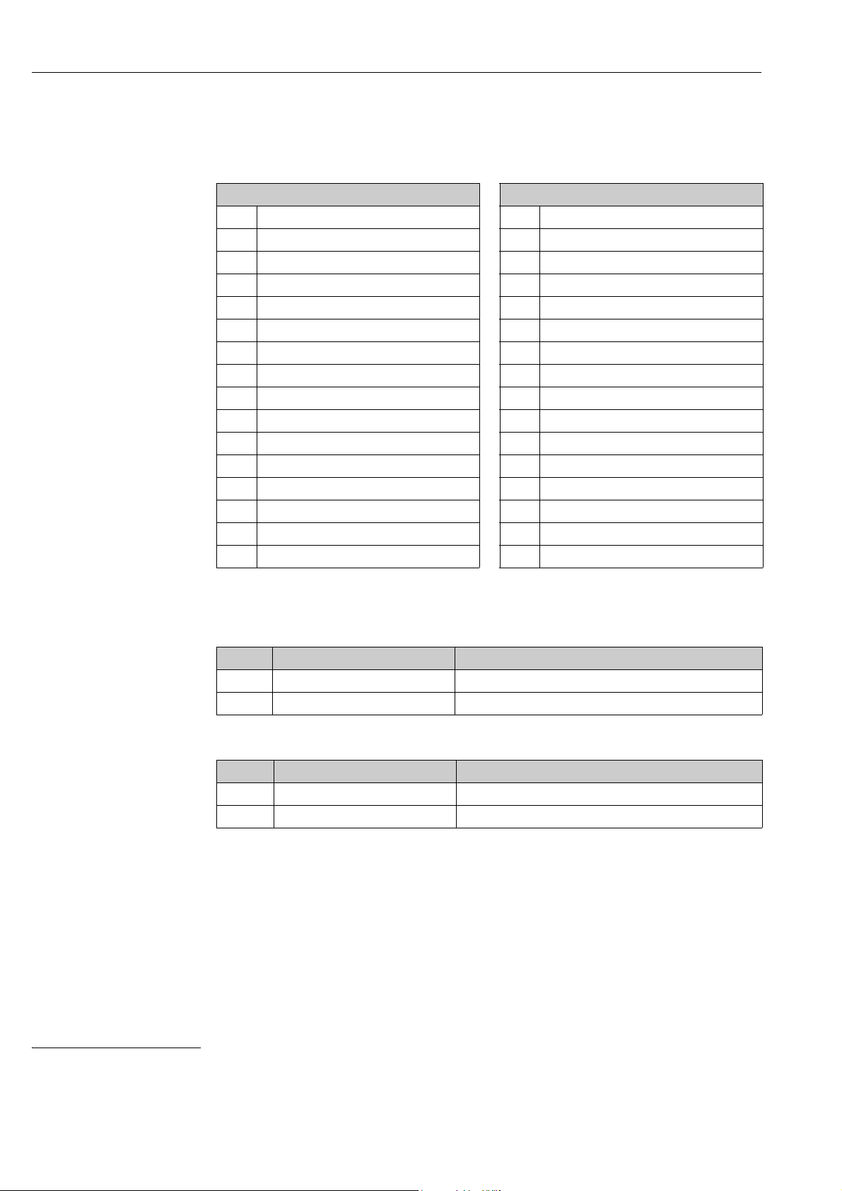
6.2.1 Error and Status codes Modbus communication
Gauge Error NMS5
Error Code Description Definition Remarks
0 No error No error present
101 OVER TENSION Measured displacer weight exceeds the Over Tension
set value at GVH 162
102 UNDER TENSION Measured displacer weight reduced below the Under
106 Z PHASE NO INPUT (2nd) Unable to recognize Z phase pulse (1 complete rotation
107 ADC/SENSOR ERROR Signal from AD converter out of the range
111 LOCAL ERROR NMT Recognize device error at the Prothermo NMT 53x
112 Z PHASE NO INPUT (1st) Unable to recognize Z phase pulse (1 complete rotation
113 LOCAL ERROR NRF Recognized device error at the Promonitor NRF560 *3
114 SIFA ERROR Local HART master IC failure on the Proservo
115 WIRE CALIB. ERROR Excess auto wire calibration range (e.g. build up on the
120 DISPLACER CALIB. ERROR Excess auto weight calibration range (e.g. deposit and
121 LCD CHECK Recognized error between display panel 3 keys control
122 A PHASE NO INPUT Unable to recognize a phase pulse (20 pulse / 1
124 POWER FAILURE Supply voltage drop below allowable value
201 MEMORY ERROR Memory defect in W&M parameters
232 LOCAL ERROR DEVICE1 Recognized device error at connected HART device 1 *3
233 LOCAL ERROR DEVICE 2 Recognized device error at connected HART device 2 *3
240 DEVICE ERROR NRF Local HART communication error to the Promonitor
250 DEVICE ERROR NMT Local HART communication error to the Prothermo
130 DEVICE ERROR: DEVICE1 Local HART communication error to the HART device 1 *3
131 DEVICE ERROR: DEVICE2 Local HART communication error to the HART device 2 *3
132 ROM ERROR Failure in the EEPROM data
133 ECONOUCE CONTACT ON Status input activated via connected switch (e.g. Leak
Tension set value at GVH 163
of encoder) to CPU after retry
*2
(Average Temperature)
of encoder) to CPU
wire)
build up on the displacer)
input to CPU
rotation of encoder) to CPU
*3
NRF560
*2
NMT53x
detector, level alarm switch)
Remarks
*2 Error code available only when the Prothermo NMT53x or 3 wire RTD SPOT
temperature bulb is connected.
*3 Error code available only when the Promonitor NRF560 or HART device 1/2 is
connected.
Endress+Hauser 19
Page 20

Operations Tankvision
Gauge Status NMS5
Error Code Description Remarks
0 No definition
1 Displacer at reference position
2 Displacer hoisting up
3None
4Displacer stop
5 Level measurement, balanced
6 Up. I/F level, balanced *1
7 Mid. I/F level, balanced *1
8 Bottom meas. balanced *1
9 Upper Dens, finished *1
10 Middle Dens, finished *1
11 Bottom Dens, finished *1
12 Release over tension
13 Calibration activated
14 Seek level
15 Follow level
16 Seek Upper Density *1
17 Seek Middle Density *1
18 Seek Density Bottom *1
19 Seek Upper I/F level *1
20 Follow up. I/F level *1
21 Seek Mid. I/F level *1
22 Follow Mid. I/F level *1
23 Seek Bottom Level
24 Not initialised
25 Stopped at High Stop.
26 Stopped at Low Stop
27 Repeatability testing
28 Seeking water level *1
29 Water level, balanced *1
30 Follow water level *1
31 Over/Under Tension
Remarks
*1 Status available when the Proservo NMS53x is implemented with Interface and Density
measurement functionality.
For NRF590 neither status codes nor error codes are available the Gauge Error/Gauge Status
are set to 0 with the status INIT to show that the data are invalid.
20 Endress+Hauser
Page 21
Tankvision Operations
6.2.2 Error and Status codes V1
Error codes NMS5
Error Code Description
0No Error
1Over Tension
2 Under Tension
3Encoder Error
4Hall Sensor Error
Status codes NMS5
Status Code Operation Status
01 Up
02 Stop
03 Bottom
04 Upper Density
05 Level
08 Upper Interface Level
09 Release Over Tension
10 Middle Density
11 Density Bottom
12 Middle Interface Level
13 Calibration Active
27 Repeatability Testing
28 Water Dipping
Endress+Hauser 21
Page 22
Operations Tankvision
6.2.3 Status Codes WM550
With WM550 the status are transferred bit coded. In Tankvision this bit sequence is shown
as decimal number which needs to be transferred into bits to be interpreted.
Gauge Error Bits Gauge Status Bits
0 Servo Check 0Gauge Servoing
1Seeking Level
2 Doing Profile
3Doing Dip 3 Stow received on port 2
4Finding BSW
5Following BSW
6Finding Datum
7Following Level
8Density Sensor
9Temp. Sensor
10 BSW Sensor
11 Datum Sensor
12 Conf. Warning
13 Liquid State 13 -
14 Liquid State Unknown
15 ISH Fitted
1Gauge Stowed
2 Stow received on port 1
4NOVRAM corrupted
5 Multielement therm. Fitted
6 Ref. Voltage is DN
7Calibration bit 0
8Calibration bit 1
9Calibration bit 2
10 -
11 -
12 -
14 -
15 -
1)
Gauge Error from NRF590 and NMS5
Tank Side Monitor NRF590 (Task 2, 3, 4, 5, 9, 11, 27, 28, 30, 31, 36, 37, 38)
Decimal Bit Coded Description
0 0000’0000’0000’0000 Level
1 0000’0000’0000’0001 Stop
Proservo NMS5 (Task 2, 3, 4, 5, 9, 11, 27, 28, 30, 31)
Decimal Bit Coded Description
0 0000’0000’0000’0000 Level
1 0000’0000’0000’0001 Stop
1) To translate the decimal number in the gauge staus/gauge error field into binary number you can use the following formular in Excel (change A1
to the field the decimal number is written):
=RIGHT(SUMPRODUCT(INT(MOD(A1/2^(ROW(16:30)-1),2))*10^(ROW(1:15)-1))&TEXT(SUMPRODUCT(INT(MOD(A1/2^(ROW(1:15)-
1),2))*10^(ROW(1:15)-1)),REPT("0",15)),INT(LN(A1)/LN(2))+1)
22 Endress+Hauser
Page 23
Tankvision Operations
Proservo NMS5 (Task 36, 37, 38)
Decimal Bit Coded Description
16386 0100’0000’0000’0010 Level unbalanced or seeking level
16388 0100’0000’0000’0100 Upper density or density seeking
16400 0100’0000’0001’0000 Upper interface level (unbalanced) or upper interface seeking
16416 0100’0000’0010’0000 Upper interface level (balanced) or upper interface following
16448 0100’0000’0100’0000 Bottom level, Bottom Density seeking or Bottom seeking
16512 0100’0000’1000’0000 Level or Level following
49154 1100’0000’0000’0010 Level unbalanced or seeking level, compatibility mode
49156 1100’0000’0000’0100 Upper density or density seeking, compatibility mode
49168 1100’0000’0001’0000 Upper interface level (unbalanced) or upper interface seeking,
compatibility mode
49184 1100’0000’0010’0000 Upper interface level (balanced) or upper interface following,
compatibility mode
49216 1100’0000’0100’0000 Bottom level, Bottom Density seeking or Bottom seeking,
49280 1100’0000’1000’0000 Level or Level following, compatibilty mode
compatibility mode
Endress+Hauser 23
Page 24
Operations Tankvision
Gauge Error from NRF590 and NMS5
Status report (Task 1) NRF590
Decimal Bit Coded Description
0 0000’0000’0000’0000 No multi element temperature fitted
32 0000’0000’0010’0000 Multe element temperature fitted
Status report (Task 1) NMS5
Decimal Bit Coded Description
1 0000’0000’0000’0001 Gauge Servoing
5 0000’0000’0000’0101 Stow received on port 1
7 0000’0000’0000’0111 Stow received on port 1, Gauge Stowed
9 0000’0000’0000’1001 Stow received on port 2
11 0000’0000’0000’1011 Stow received on port 2, Gauge Stowed
21 0000’0000’0001’0101 NMS Error Code present (see below), Stow received on port 1
23 0000’0000’0001’0111 NMS Error Code present (see below), Stow received on port 1,
Gauge Stowed
25 0000’0000’0001’1001 NMS Error Code present (see below), Stow received on port 2
27 0000’0000’0001’1011 NMS Error Code present (see below), Stow received on port 2,
Gauge Stowed
33 0000’0000’0010’0001 NMT connected, Gauge Servoing
37 0000’0000’0010’0101 NMT connected, Stow received on port 1
39 0000’0000’0010’0111 NMT connected, Stow received on port 1, Gauge Stowed
41 0000’0000’0010’1001 NMT connected, Stow received on port 2
43 0000’0000’0010’1011 NMT connected, Stow received on port 2, Gauge Stowed
53 0000’0000’0011’0101 NMS Error Code present (see below), NMT connected, Stow
received on port 1
55 0000’0000’0011’0111 NMS Error Code present (see below), NMT connected, Stow
received on port 1, Gauge Stowed
57 0000’0000’0011’1001 NMS Error Code present (see below), NMT connected, Stow
59 0000’0000’0011’1011 NMS Error Code present (see below), NMT connected, Stow
received on port 2
received on port 2, Gauge Stowed
NMS Error Codes
Error Code Description
101 Over Tension
102 Under Tension
106 Z Phase no Input (2)
107 ADC Sensor Error
112 Z Phase no Input
115 Wire calibration error
120 Displacer calibration error
122 A Phase no input
24 Endress+Hauser
Page 25

Tankvision Operations
1.
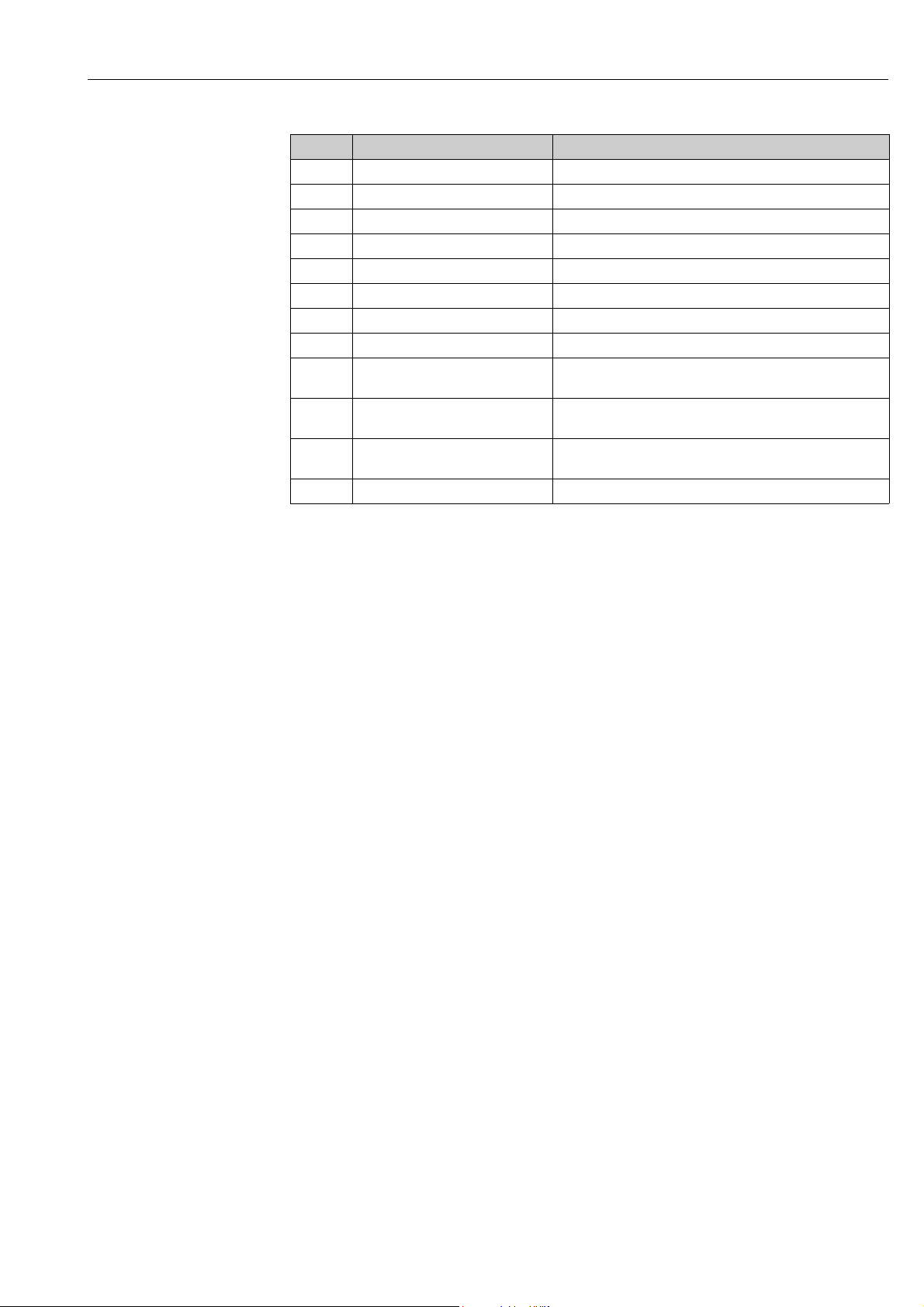
6.2.4 WM550 Task-51
The WM550 protocol offers only a limited value resolution and therefore an additional
Task-51 has been added to the WM550 protocol for the Tank Side Monitor NRF590. This
Task-51 can be added to the foreground task in gauge map file as shown below:
NXA82x_WM550_Task51
The Task-51 delivers a predefined set of information which is described in the table below.
Measured Value Tank Parameter Granularity Units
Level Product Level 1 mm
BSW Water Level 1 mm
Temperature Product Temperature 0.1 °C
Temperature Vapor Temperature 0.1 °C
Pressure P1(Bottom) Pressure 0.01 bar
Pressure P2(Middle) Pressure 0.01 bar
Pressure P3 (Top) Pressure 0.01 bar
Density Observed Density 0.1 kg/m3
6.3 How to view Temperature Profiles
The below described operations can be performed with the default user access rights for an
operator ("User access rights", → ä 13).
The Temperature Profile tab displays measured values from the spot elements of an
average temperature probe, if configured.
Depending on the system architecture this parameters might be used for displaying
other values than temperatures.
To view the Temperature Profile tab
On the Tank Details screen, click the Temperature Profile tab. Tankvision displays the
screen as follows:
Temperature_Profile
Endress+Hauser 25
Page 26

Operations Tankvision
1.
The table presents the temperature profile data according to the corresponding
Temperature Index (element number, where the lowest element is the element number 1).
This information is also presented graphically next to this table in the Temperature Graph.
The amount of elements to be displayed (according to the average temperature probe which
is in use) can be selected in the Temperature Profile Configuration section.
6.4 How to view Density Profiles
The below described operations can be performed with the default user access rights for an
operator ("User access rights", → ä 13).
The Density Profile tab displays measured values from the spot elements of an average
density probe, if configured.
Depending on the system architecture this parameters might be used for displaying
other values than densities.
To view the Density Profile tab
On the Tank Details screen, click the Density Profile tab. Tankvision displays the
screen as follows:
NXA82x_Density_Profile
The table presents the density profile data according to the corresponding Density
Positions. This information is also presented graphically next to this table in the Density
Graph.
The amount of elements to be displayed (according to the average density probe which is in
use) can be selected in the Density Profile Configuration section.
26 Endress+Hauser
Page 27

Tankvision Operations
1.
2.
6.5 How to view and enter Manual Data
The below described operations can be performed with the default user access rights for an
operator ("User access rights", → ä 13). The Manual Data tab gives you the option of
entering values for the product level, temperature, density and pressure manually.
Functionality is depending on the user right settings.
Selection of Parameters for manual data entry
Click the Manual Data tab. With opening the Set/Configure Manual Parameters the
following screen for selecting parameters for manual data entry is shown.
NXA82x_Manual-Data_Set-Confi gure-Manual-Parameters
The user can select one or several parameter from the available parameter list and move
them to the selected parameter list by using > button and clicking Submit. Using >>
moves all available parameters in the selected Parameters (deselecting works in
accordance by using the < or << buttons). From the following list the parameters can be
chosen (see below):
Field Description
Product level Enter the appropriate value for the product level in the according text box.
Water level Enter the appropriate value for the water level in the according text box.
Product Temperature Enter the appropriate value for the product temperature in the according text box. This
Vapor Temperature Enter the appropriate value for the vapor temperature in the according text box. This
Ambient
Temperature
Observed Density Enter the appropriate value for the observed density in the according text box. This field
Sample Temperature Enter the temperature at which the density of the sample was measured in the according
Reference Density Enter the appropriate value for the reference density in the according text box. This field
The data type for this field is numeric.
The data type for this field is numeric.
field displays the temperature of the product in the tank. The data type for this field is
numeric.
field displays the temperature of the vapor in the tank. The data type for this field is
numeric.
Enter the appropriate value for the ambient temperature in the according text box. This
field displays the ambient temperature outside the tank. The data type for this field is
numeric.
displays the observed density of the product in the tank. The data type for this field is
numeric.
text box. This field displays the temperature of the density sample. The data type for this
field is numeric.
displays the reference density of the product in the tank. The data type for this field is
numeric.
Endress+Hauser 27
Page 28

Operations Tankvision
3.
1.
2.
3.
4.
Field Description
Vapor Pressure Enter the appropriate value for the vapor pressure in the according text box. This field
displays the vapor pressure of the product in the tank. The data type for this field is
numeric.
In the radio buttons below mark the pressure measurement method: absolute or
relative.
Pressure Enter the appropriate value for the pressure in the according text box. This field displays
the pressure of the product in the tank. The data type for this field is numeric.
In the radio buttons below mark the pressure measurement method: absolute or
relative.
Tankvision will show a confirmation message and the parameters are now available to
enter manual values.
To enter manual data
Click the Manual Data tab. Tankvision displays the screen as follows:
NXA82x_Manual-Data_Enter-Manual-Parameters
Column Description
Parameter Name This column displays a list of the tank parameters that can be configured manually.
Manual Gauge Value This column displays the text boxes that allow the user to enter the data for the relevant
parameter.
Enter the appropriate information in the relevant fields.
Click the Submit button.
After saving the settings, Tankvision displays a confirmation message.
An event is generated after manually entering a value for a tank parameter. The event
details can be viewed in the Event overview.
28 Endress+Hauser
Page 29

Tankvision Operations
6.6 How to enter dipped data
The below described operations can be performed with the default user access rights for an
operator ("User access rights", → ä 13).
The Dipped Data tap gives you the option of entering dipped values for the product level,
water level, product temperature, observed density with acc. sample temperature and the
reference density.
Dipped Data
Field Description
Product level Enter dipped values for the product level. Activate the field by enabling the check box in
the beginning of the column.
Water level Enter dipped values for the water level. Activate the field by enabling the check box in the
Product temperature Enter dipped values for the product temperature. Activate the field by enabling the check
Date and Time Enter the appropriate Date and Time in the text box / drop down list. This time will be
beginning of the column.
box in the beginning of the column.
used as time stamp for the manually entered value. The data type for this field is time.
6.7 How to issue gauge commands
The below described operations can be performed with the default user access rights for an
operator ("User access rights", → ä 13).
Every gauge supports a specific set of commands. The Tankvision system supports these
gauges and stores their data and corresponding gauge commands in "gauge definition files".
The functionality of gauge commands is dependent on the gauge type assigned to the tank,
whereas completion of a gauge command is based on the gauge status or gauge commands
status. The Tankvision system retrieves these commands from the "gauge definition files"
during the configuration of gauge commands. Gauge commands can be scheduled and sent
only by an authorized user. Most of these commands are unique for servo gauges. You can
send a gauge command to a gauge installed on a tank manually or even schedule a gauge
command to be sent automatically.
Tankvision Tank Scanner prevents the user to send the same gauge command multiple times
to a servo gauge (i.e. the Tank Scanner only sends gauge command once to the servo gauge
and ignores the gauge command until a new command is requested). This applies for gauge
command requests via the Host Link, OPC DA or the web interface.
In case a gauge command has been given to the servo gauge via a separate way (e.g. directly
from the display), then the Tank Scanner will not get this information. In this case simply by
sending a different gauge command and switching back to the gauge command will solve the
issue.
6.7.1 Schedule Gauge Command
The Tankvision system allows the user to schedule gauge commands, such that they can be
executed either immediately or at a certain time. An operator can schedule a gauge
command only if that particular gauge command is enabled in the Gauge Command
configuration screen.
Endress+Hauser 29
Page 30

Operations Tankvision
1.
2.
3.
To schedule a gauge command
Click the Gauge Commands tab. Tankvision displays the screen as follows:
Gauge_Commands
Click on Schedule Gauge Command. Tankvision displays the screen as follows:
NXA82x_Tank_Gauge-Commands-Tab
Field Description
Gauge Type This field displays the Gauge Type.
Gauge Command Select the appropriate gauge command from the drop down list.
Schedule Type Select the appropriate Schedule type from the drop down list. The gauge command can be
Interval Enter the appropriate interval in the text box. This field is enabled if the Schedule Type
Date Enter or select the appropriate date from the drop down calendar. The Tankvision system
Status Select the appropriate option. This field indicates the status of the gauge command. This
The data type for this field is "character".
scheduled to be sent once or scheduled for automatic repetition.
Sent Once: Select sent once to enable the gauge command to be sent only once.
Automatic Repetition: Select automatic repetition to enable the Interval field.
This field allows you to schedule the system to send a particular gauge command
periodically. The data type for this field is "character".
for the gauge command is selected as Automatic Repetition. The data type for this field
is "numeric".
Also, in the adjacent text box:
Select the appropriate unit for the interval from the drop down list. The system allows
you to schedule the interval for the gauge commands in terms of hours or minutes.
The data type for this field is character.
allows you to select the date on which the gauge command is to be sent. The data type for
this field is alphanumeric. Also, enter or select the appropriate time in terms of hours and
minutes from the respective drop down lists. The Tankvision system allows you to select
the exact time at which the gauge command is to be sent. If the Schedule Type for a
gauge command is "automatic repetition", then the time entered in the text boxes
indicates the first time the gauge command is to be sent. The data type for this field is
numeric.
field allows you to enable or disable a gauge command.
Enter the appropriate information in the relevant fields.
30 Endress+Hauser
Page 31

Tankvision Operations
4.
5.
Click the "Submit button to send a gauge command, or click the Reset button to exit.
After saving the settings, Tankvision displays a confirmation message.
The system generates an event, when the Gauge Command is sent. This information
can be viewed in the Event tab.
Error Messages
1. "Cannot send gauge command while tank status is Manual, In Maintenance, or Locked."
This message appears when the user sends a gauge command while tank status is
Manual, In Maintenance or Locked.
Endress+Hauser 31
Page 32

Operations Tankvision
1.
2.
3.
4.
5.
6.7.2 Send Gauge Command
The Tankvision system allows you to send commands to a gauge installed on a tank. A gauge
command can be sent only if that particular command is enabled for the tank in the Gauge
Command configuration screen. Once a gauge command is sent, it remains active till the
system receives an appropriate response from the gauge. The response for a gauge
command depends on the gauge and communication protocol.
The Tankvision system allows the user to send gauge commands via following interfaces:
1. Via Tankvision Tankscanner web interface
2. Via connected Host application with NXA822
3. Via OPC Server
To send a gauge command
Click the Gauge Commands tab. Tankvision displays the screen as follows:
Gauge_Commands
Click on Send Gauge Command. Tankvision displays the screen as follows:
NXA82x_Gauge-Commands_Send-Gauge-Co mmand
Field Description
Product level
Product temperature
Status
Date and Time
Column Description
Select Select the appropriate gauge command option corresponding to the gauge command
Gauge Command This column displays a list of gauge commands in abbreviated form.
Description This column displays a short description corresponding to each gauge command.
Displaying Product Level and Product Temperature incl. Status
Displaying Active Gauge Command and issuing Date and Time
name.
The radio buttons are highlighted only if the corresponding gauge commands are
configured in the Gauge Command screen.
Select the appropriate gauge command option.
Click the Send button to activate the gauge command.
After saving the settings, Tankvision displays a confirmation message as follows:
32 Endress+Hauser
Page 33

Tankvision Operations
6.
NXA82x_Gauge-Commands_Send-Gauge-Command_Successfully
In the above figure, all options in the Select column are disabled, except the Stop option.
If the gauge command has to be stopped, then select the stop option, and click the Send
button.
If another gauge command needs to be sent, it might be necessary to cancel the active
command by sending the STOP command prior issuing the new command.
The system generates an event, when a Gauge Command is activated. This information
can be viewed in the Event tab.
Error Messages
1. "Cannot send gauge command while tank status is Manual, In Maintenance, or Locked."
This message appears when the user sends a gauge command while the tank status is
Manual, In Maintenance or Locked.
Endress+Hauser 33
Page 34

Operations Tankvision
1.
2.
6.8 How to view a real time trend
The below described operations can be performed with the default user access rights for an
operator ("User access rights", → ä 13).
The Tankvision system collects data from the tanks and monitors these values using a trend.
A trend is a line graph which gives a pictorial representation of the recent changes of the
measured values over time. The Real Time Trend is hosted in the Tankvision unit. It depicts
the real-time measured or calculated values of a selected tank as a function of time in the
form of a line chart.
The system has default settings which can be customized as required for each tank element
and will eventually be plotted on the trend. Up to 4 values can be plotted in one chart.
To view a real time trend
In the navigation tree, click the Trends header. Click Real Time trend. Tankvision
displays the screen as follows:
NXA82x_Trends_Real-Time-Tren ds_Trend-Configuration
Section Description
Pen settings This section displays a list of pens (Pen 0, Pen 1, Pen 2 and Pen 3) that are used to
identify the parameters selected. Select the appropriate tanks, parameters, pen colors
and pen style from the respective drop down lists.
Global trend settings Select the Background color, Grid color and Plot Cursor color from the respective drop
down lists.
Trend preview See a preview of the real time trend plot with the currently selected settings.
Select the appropriate settings and click the apply button. Tankvision displays the
screen as follows:
34 Endress+Hauser
Page 35

Tankvision Operations
NXA82x_Trends_Real-Time-Trends_T rend-Configuration
The line graphs are displayed based on the selection of tank parameters in the Trend
Configuration area.
A plotter can be moved through the graphic area. According to the position of the plotter
values are displayed in a field next to it. For example:
NXA82x_Trends_Real-Time-Trends _Trend-Configuration_Plotter
Click and drag with the mouse to zoom into the graph.
Field Description
Period The Period icons allow you to make changes to the current time window. The selected
period (last 6 hours, 3 hours, 90, 60, 30, 15, 10, 5 minutes or the last minute) is
displayed in the plotting area.
print chart The print chart icon lets you print the current real time trend chart with a connected
printer.
Endress+Hauser 35
Page 36

Operations Tankvision
Field Description
Pan The Pan icons allow you to make changes in the current time window displayed in trend.
The Go First button rewinds the trend to the oldest available values in the rolling
data buffer of the trend.
The Go Previous button shows the previous time window.
The Go Next button shows the next time window.
The Go Last button shows current or latest values in the trend.
run/stop The run/stop icon lets you run or stop the real time trend. When the trend is running,
run is displayed. When the trend is stopped, stop is displayed.
36 Endress+Hauser
Page 37

Tankvision Operations
1.
2.
3.
4.
6.9 How to assign/change products at a tank
The below described operations can be performed with the default user access rights for an
operator ("User access rights", → ä 13).
After configuring a product, it has to be assigned to a tank. The user can assign only one
product to a tank. A product which is currently assigned to a tank can not be deleted from
the system.
To assign a product to a tank
Click the Assign Product tab. Tankvision displays the screen as follows:
Assign Product
Field Description
Product Select the appropriate product from the drop down list.
This field enables the system to assign a product to a specific tank.
Sediment and Water
Percentage
Enter the appropriate sediment and water percentage for the selected product. The
Tankvision system uses the sediment and water percentage in tank inventory
calculations and corrects the product volume according to the sediment and water
content.
The data type for this field is numeric.
Enter the appropriate information in the relevant fields.
Click the Submit button to assign the product to the tank.
After saving the settings, Tankvision displays a confirmation message.
Once the product is assigned to the tank, the tank is automatically added to the builtin product group, and the tank can be seen in the navigation tree of the screen under
the Products Header.
An event is generated after a product is assigned to a tank. The event details can be
viewed in the Event overview.
Endress+Hauser 37
Page 38

Operations Tankvision
1.
6.10 How to do Product transfer
The below described operations can be performed with the default user access rights for an
operator ("User access rights", → ä 13).
The product transfer is a day-to-day tank farm operation. During the tank farm operation, a
product is pumped into or out of a tank. A tank may receive product from a pipeline, tanker,
ship or another tank. When the product is to be filled into a tank, it is necessary to check the
available tank capacity. Similarly, when the product is to be pumped out of a tank, it is
necessary to check the product volume in the tank. Tankvision allows an operator to create
a new product transfer.
Tankvision does not control the product transfer, but it monitors product transfers and
generates product transfer data and reports. When a company sells the product stored in
tanks to another company, it is important that the tank is W&M (weights and measurement)
certified for correct measurements. The Tankvision system provides this facility by
calibrating the system and then gets it W&M approved. All tanks which are W&M certified
can be used for custody transfers.
In this case the product transfer report (→ ä 44) will mention the W&M approved status,
which can be used to prove that the correct amount of product has been transferred.
6.10.1 Product Transfer Life Cycle
The Tankvision system allows the user to create, finish or abort a product transfer. Once a
product transfer is created, the system monitors the product transfer to detect "start of
transfer (active)", "product transfer paused" or "product transfer completed".
The life cycle of a product transfer
The product transfer traverses through its life cycle as follows:
• Create a product transfer for a tank
• Detection of the start of the product transfer
• Detection of a paused transfer
• Detection of a completed transfer
• Transfer finished or aborted
• Product transfer report
To transfer a product for a tank
Click the Product Transfer tab. Tankvision displays the screen as follows:
Field Description
Source/Destination The system displays the status of inflow or outflow of the product. If the transfer type is In,
then this field displays Source. If the transfer type is Out, then this field displays
Destination.
38 Endress+Hauser
Product_Transfer_red
Page 39

Tankvision Operations
Batch [%]
Max.
Min.
100%
0
t
Field Description
Transfer Type Select the appropriate product transfer type from the drop down list. This field enables the
system to allow transfer of the product into or out of the tank depending on the selected
option, viz., In or Out.
In: A product is being filled into a tank.
Out: A product is being pumped out from a tank.
This field is disabled after creating a new product transfer.
Batch Mode Select the appropriate batch mode from the drop down list. This field allows you to select
the mode of product transfer. The batch mode is Volume or Mass.
Volume: The quantity of product to be transferred is specified as Total Observed Volume
(TOV) of product.
Mass: The quantity of product to be transferred is specified as product Mass.
This field is disabled after creating a new product transfer.
Batch Size Enter the appropriate batch size in the text box. This field displays the quantity of the
product that is being transferred. The unit depends on whether the mode of product
transfer is in volume or mass. The data type for this field is numeric.
Batch Deviation
Percentage
Minimum
Enter the minimum batch percentage.This
field is used to determine, whether the
product transfer is complete or not. The
product transfer is considered as completed,
if:
• The quantity of product that has been
transferred so far (calculated as per batch
mode) is equal to or more than the
minimum batch deviation percentage of
the batch size, and ...
• ... the rate of change of volume is less than the minimum rate of change of the volume
The data type for this field is numeric.
Maximum
Enter the maximum batch percentage. This
field is used to determine, whether the
product transfer is complete or not. The
product transfer is considered as completed,
if:
• If the batch exceeds the max. batch
percentage an event is generated.
• The quantity of product that has been
transferred so far (calculated as per batch
mode) is equal to or more than the
minimum batch deviation percentage of
the batch size and is less than the
maximum batch deviation percentage of
the batch size; and ...
Pre Alarm
Percentage
Comments Enter the appropriate comments in the comments field. This field allows the user to enter
E-Mail Addresses Enter the appropriate e-mail addresses. Whenever the product transfer is completed, the
Transfer Status This field displays the status of the product transfer. The product transfer status can be:
Enter the pre-alarm percentage. If the quantity of product transfered (calculated as per the
batch mode) increases above the pre alarm percentage of the batch size for In transfer or
decreases below the pre-alarm percentage for Out transfer, then the system raises a prealarm.
The data type for this field is numeric.
comments related to the product transfer. This information is captured in the product
transfer report. The data type for this field is characters.
system sends a product transfer report by e-mail to the e-mail addresses entered in this
field.
"Armed", "Active", "Paused", "Completed", "Finished" or "Aborted".
• "Armed" (Ready to start)
• "Active" (In progress)
•"Paused" (On hold)
• "Completed" (if min. batch dev. percentage is reached 0 and flow goes to 0)
• "Finished" (tank transfer finished)
• "Aborted" (stop immediately before finishing)
Endress+Hauser 39
Page 40

Operations Tankvision
2.
3.
4.
Below the Product Transfer Configuration, the Product Transfer Overview is displayed.
Enter the appropriate information in the relevant fields.
Click the Submit button to create a new product transfer.
After saving the settings, Tankvision displays a confirmation message.
An event is generated after creating a product transfer. The event details can be viewed
in the Event overview.
6.10.2 Status of a Product Transfer
Create a New Product Transfer
Creating a new product transfer is the first step to be followed after the pre-condition for
product transfer is set in the system. While creating a new product transfer, the transfer
status of the tank should be "None". The product transfer status "None" means that the tank
does not have any product transfer associated with it in the Armed or Active status, and thus
a new product transfer can be created. An image of Tankvision displaying the status as
"None" is as follows:
Product_Transfer
Validate product transfer details
Once the user has created a new product transfer for a tank, this tank is said to be "Armed"
for product transfer. The system starts monitoring a tank (with status) "Armed" to
automatically detect the start of the product transfer. Auto detection of start of Product
transfer defined in. Once a tank is armed for a product transfer, no other product transfer
can be created for the tank, unless the existing transfer is cancelled.
An image of Tankvision displaying the status as "Armed" is as follows:
Product_Transfer_ Status-Armed
The system generates an event when the status is changed from "None" to "Armed". This
information can be viewed in the Event tab.
40 Endress+Hauser
Page 41

Tankvision Operations
Detection of the start of a product transfer
Once the product transfer has been armed, the system detects the start of the product
transfer based on a change in the level and the rate of change of the level. The system treats
the product transfer as started and the product transfer status is changed to "Active" if:
• The change in product level is greater than the minimum level change, and
• The rate of change of level is greater than the minimum rate of change of level configured
under the flow calculation details
Once a tank is in the "Active" status for a product transfer, no other product transfer can be
created for the tank, unless the active transfer is Finished or Aborted.
An image of Tankvision displaying the status as "Active" is as follows:
Product_Transfer_active
Product transfer paused
The system treats an Active product transfer as Paused and the product transfer status is
changed to "Paused" if:
• the flow rate drops below the minimum volume change rate,
• the rate of change of level drops below the minimum rate of change of level configured
under the tank flow calculation details, and
• the quantity of product that has been transferred is less than the minimum batch deviation
percentage of the batch size
An image of Tankvision displaying the status as "Paused" is as follows:
Status- Paused_NXA820
Endress+Hauser 41
Page 42

Operations Tankvision
Product transfer completed
The product transfer is considered as completed, if:
• The quantity of product that has been transferred so far (calculated as per batch mode) is
equal to or more than minimum batch deviation percentage of batch size, and is less than
the maximum batch deviation percentage of the batch size; and
• the rate of change of volume is less than the minimum rate of change of volume
An image of Tankvision displaying the status as "Completed" is as follows:
Status- Completed_NX A820
The system generates an event for a completed product transfer. The event details can
be viewed in the Event tab.
Product transfer finished
The user may choose to finish the product transfer before the product transfer is completed.
The product transfer can be finished, when the tank is in an "Active" transfer stage.
An image of Tankvision displaying the status as "Finished" is as follows:
Status- Finished_NXA820
The system displays a pop up message to confirm about finishing the product transfer.
•When the user manually finishes the product transfer, the system generates and
displays the Product Transfer Report.
•The system generates an event for product transfer finished by user. The information
can be viewed in the Events tab.
•The user cannot manually finish the product transfer, if the product transfer status is
"Completed".
Product transfer aborted
The user may choose to abort the product transfer before the product transfer is completed.
The product transfer can be "Aborted", when the tank is in an "Active" transfer stage. When
the product transfer is aborted, the system does not record the data of starting and ending
of product transfer. In such case, the system maintains different sets of data. The data of a
42 Endress+Hauser
Page 43

Tankvision Operations
previously completed or finished product transfer are preserved, and the data of the aborted
product transfer are discarded.
Status- Aborted_NXA8 20
The system displays a pop up message to confirm about the aborting of the product
transfer.
The system generates an event for an aborted product transfer. The event details can
be viewed in the Event tab.
Error Messages
1. "Tank cannot be armed for product transfer if "No product" has been assigned to tank"
This message appears when the user attempts to create a product transfer when "No
Product" is assigned to the tank.
2. "The Tank status is "Locked", cannot create a new product transfer for a tank that is
locked"
This message appears when the user attempts to create a product transfer when the
tank status is "Locked".
3. "The Tank status is "In Maintenance", cannot create a new product transfer for a tank
that is in maintenance"
This message appears when the user attempts to create a product transfer when the
tank status is "In Maintenance".
4. "Batch size cannot be zero, if you do not wish to specify batch size leave the field empty"
This message appears when the Batch size entered by the user is equal to zero.
5. "Batch size should be greater than zero"
This message appears when the value of the Batch size entered by the user is less than
zero.
6. "Batch size should be smaller than remaining tank capacity"
This message appears when the transfer type is "In" and the batch size entered by the
user is more than the remaining tank capacity.
7. "Batch size should be smaller than available product quantity"
This message appears when the transfer type is "Out" and the batch size entered by the
user is more than the available product quantity.
8. "Minimum batch deviation should be less than maximum batch deviation"
This message appears when the Minimum batch deviation entered by the user is greater
than or equal to maximum batch deviation.
9. "Pre-alarm percentage should be greater than zero"
This message appears when the Pre-alarm percentage entered by the user is less than
or equal to zero.
10. "Pre alarm percentage should be less than minimum batch deviation"
This message appears when the pre-alarm percentage entered by the user is more than
the minimum batch deviation.
Endress+Hauser 43
Page 44

Operations Tankvision
1.
2.
6.11 How to view a Transfer report
The below described operations can be performed with the default user access rights for an
operator ("User access rights", → ä 13).
The Tankvision system allows the user to arm a tank for product transfer, and is set up to
detect the start and end of the product transfer details for a tank. The system records the
product transfer data and generates a report for the product transfer with "Completed" and
"Finished" statuses, using an appropriate template. You can view or even edit the product
transfer report for the last product transfer that has been completed by the system.
To generate a product transfer report
In the navigation tree, click the Reports header. Click Product Transfer Report.
Tankvision displays the screen as follows:
Product Transfer Report_NXA820
Field Description
W&M Approved This section displays the status of W&M approval.
Configuration Setting
Details
Product Transfer
Details
Element Name This section displays the result of the product transfer in terms of parameter changes.
This section displays the report of the configuration settings.
This section displays the report of Product Transfer settings.
Refer to "Product Transfer Life Cycle" (→ ä 38) for details.
Refer to "Tank Calculator" (→ ä 48) for details.
Refer to the "View Product Transfer Report" section under the "Reports" chapter for more
information on the product transfer report.
44 Endress+Hauser
Page 45

Tankvision Operations
1.
2.
3.
4.
6.12 How to view and change Tank Status
The below described operations can be performed with the default user access rights for an
operator ("User access rights", → ä 13).
The tanks in the Tankvision system are associated with a status which can be changed by the
operator.
To change the tank status for all tanks at once, go to the Configuration → Tank Status
page, → ä 47.
To change the tank status
Click the Tank Status tab. Tankvision displays the screen as follows:
Tank_Status
Field Description
Current Status The system displays the current status of the tank.
Change Status to Select the appropriate status type from the drop down list. This field allows you to select
the status in which the tank is required to function. The statuses are:
• In Operation: The tank is in normal operation.
• In Maintenance: The tank is under maintenance. A tank is always empty under
maintenance, and tank operations such as gauge commands or product transfers
cannot be performed. The field scan is not needed.
• Manual: The tank is in operated manually, which means the system will not measure
the data automatically. All tank parameters are in manual mode and the field scan is in
off mode. A product transfer can occur.
• Locked: The tank is generally filled but locked to disallow product transfer. All other
activities can be performed.
Refer to "Tank Status Change Matrix" (→ ä 45) for the activities that can be performed
under various tank statuses, and to "Tank Status Indicator" (→ ä 46) to learn about the
notification on the tank status graph.
Enter the appropriate information in the relevant fields.
Click the Submit button to change the tank status.
After saving the settings, Tankvision displays a confirmation message.
An event is generated after changing the tank status. The event details can be viewed
in the Event overview.
6.12.1 Tank Status Change Matrix
The activities that can be performed under various tank statuses are as follows:
Activity vs Tank Status In Operation Manual Maintenance Locked
Inventory Calculation Yes Yes No Yes
Product Transfer Yes Yes No No
Gauge Commands Yes No No No
Raise Change in Volume Alarm No No No Yes
Field Scan Yes No No Yes
Raise Alarms Yes No No Yes
Endress+Hauser 45
Page 46

Operations Tankvision
6.12.2 Tank Status Indicator
Tankvision indicates the tank status on the Tank Overview section on the Tank Details tab.
When the tank status is modified to "In Operation", the system indicates the tank status on
the Tank Overview section as follows:
NXA82x_Tank-Status-Indicator_Ope ration
When the tank status is modified to "In Maintenance", the system indicates the tank status
on the Tank Overview section as follows:
NXA82x_Tank-Status-Indicator_M aintenance
When the tank status is modified to "Manual", the system indicates the tank status on the
Tank Overview section as follows:
NXA82x_Tank-Status-Indicator_Man ual
When the tank status is modified to "Locked", the system indicates the tank status on the
Tank Overview section as follows:
46 Endress+Hauser
Page 47

Tankvision Operations
1.
2.
3.
4.
NXA82x_Tank-Status-Indicator_L ocked
6.12.3 Changing the TankStatus for all Tanks at once
To change the tank status for all tanks at once
In the navigation tree, click the Configuration header. Click Tank Status. Tankvision
displays the screen as follows:
NXA82x_Configuration_Tank-Stat us
Set the statuses of the tanks with the Change Status To picklists. To change all tanks to
the same status, select All Tanks.
Click the Submit button to change the tank statuses.
After saving the settings, Tankvision displays a confirmation message.
An event is generated after changing the tank status. The event details can be viewed
in the Event overview.
Endress+Hauser 47
Page 48

Operations Tankvision
1.
2.
6.13 How to do tank calculations
The below described operations can be performed with the default user access rights for an
operator ("User access rights", → ä 13).
The Tankvision system performs inventory calculations based on the measured data scanned
from a gauge or entered manually. The system uses the tank and product configuration
mainly to perform these calculations. Tankvision provides a tank calculator to evaluate
various "what if" scenarios. These scenarios could be:
• What would be the product volume for a certain product level?
• What would be the product level, if a certain quantity of product is pumped into the tank?
• What would be the product volume, if the product level is equal to the high level alarm?
Based on the above mentioned scenarios, the tank calculator would also indicate whether
the resulting tank parameter could cause an alarm.
Thus, prior to an actual product transfer, the tank calculator can be used to verify whether
it is possible to perform an "out" or "in" product transfer without resulting in an alarm. Any
tank parameter that is changed in the tank calculator is used to carry out calculations and
display results to evaluate the what-if scenarios. Changing tank parameters in the tank
calculator does not change the actual tank data.
To use the tank calculator
Click the Tank Calculator tab. Tankvision displays the screen as follows:
NXA82x_Tank_Tank-Calculato r--Tab
Column Description
Parameter This column displays a list of product parameters for which the start and end value can be
entered for the purpose of calculation.
Start Value Enter the appropriate start values for the relevant parameters in the corresponding text
boxes.
The start value is the initial value of the parameter. For example, the initial level of the
product will be the start value for Product Level. The data type for this field is numeric.
End Value Enter the appropriate end values for the relevant parameters in the corresponding text
boxes.
The end value is the current or final value of parameter. For example, the current or final
level of the product will be the end value for Product Level. The data type for this field is
numeric.
Delta Value The delta values are not editable. The delta value is the difference between the start value
and the end value of a parameter. The data type for this field is numeric.
Enter the appropriate information in the relevant fields and click the Calculate button.
48 Endress+Hauser
Page 49

Tankvision Operations
1.
2.
3.
4.
6.14 How to view products groups
The below described operations can be performed with the default user access rights for an
operator ("User access rights", → ä 13).
The Tankvision system has a product-tank group feature, where the user can view different
products stored in various tanks.
To view the product-tank group
On the Navigation Tree, click the Products header. (The number of products configured
is displayed in brackets next to the header’s name.) The Products header expands as
follows:
NXA82x_Menu_Products
In the above figure, the <Product Name> created by the authorized personnel is
displayed under the Products header. The number shown inside the bracket, is the total
number of tanks that contain the product.
Click the <Product Name> to display the tanks filled with the relevant product.
Tankvision displays the screen as follows:
Tabular_View_of_the_Product
By default, the system displays the tabular view of the product group in the Products-
<Product Name> screen.
Click the , the system will expand the node and display the names of the tanks that
have this product. The user may click on the <Tank Name> to view the detailed
information about the tank.
Endress+Hauser 49
Page 50

Operations Tankvision
1.
6.14.1 Graphical View of the Product-Tank Group Details
To view the product-tank group details in graphical format
On the Products - <Product Name> screen, click the Graphical View tab. Tankvision
displays the screen as follows:
NXA82x_Product-Tank-Groups_Grap hical-View
Field Description
<Tank Name> und
<Product Name>
Level of Alarm The current level of alarm is displayed as per the alarm set point.
Graphical Bar The graphical bar displays the product level and water level.
Product Parameter Each tank’s measured data, viz., product level and product temperature are displayed
Tanks in a Tank
group
The tank names and the product names are displayed for the selected tank group.
with the appropriate units. The system also indicates the alarm acknowledgement status
using different background colors. The background colors are as follows:
• Dark green - indicates an active and acknowledged alarm
• Light red - indicates an active and unacknowledged alarm
• Yellow - indicates an inactive and unacknowledged alarm
• White - indicates an inactive and acknowledge alarm
The total number of tanks in a tank group is displayed as per the tank group parameter.
A guest user can view the Non Real Time Product-Tank Group Details screen. The
system displays the measured graphical information of the tanks, when the <Product
Name> is selected. The user has to manually refresh the screen to view the latest
measured graphical information.
Click on Configuration. Tankvision displays the screen as follows:
NXA82x_Product-Tank-Groups_Graphical-View_Configuration
Select the secondary parameters that are displayed in the Graphical View from the drop
down lists.
Click the save button to save the configuration. The configuration is changed for all tanks.
Click cancel to exit.
50 Endress+Hauser
Page 51

Tankvision Operations
1.
1.
6.14.2 Tabular View of the Product-Tank Group Details
To view the product-tank group details in tabular format
On the Products - <Product Name> screen, click the Tabular View tab. Tankvision
displays the screen as follows:
Tabular_View_of_the_Product
Description of the screen:
1. Displayed columns are selectable (how to add columns to the tabular view, see below):
Tank Name, Product Name, Movement Direction, Level Alarms, Product Level,
Secondary Level, Water Level, Product Temperature, Vapour Temperature, Vapour
Pressure, Observed Density, Ambient Temperature, Reference Density, Total Observed
Volume (TOV), Remaining Tank Capacity, Available Product Volume, Sediment Water
Volume, Rate of Change of Level, Rate of Change of Volume, Net Standard Flow Rate,
Total Mass Flow Rate, Free Water Volume (FWV), Gross Observed Volume (GOV),
Gross Standard Volume (GSV), Net Standard Volume, Product Mass, Total Mass, Total
Standard Volume, VCF, Mass in Vapor, Net Weight in Air, Net standard Weight,
floating roof adjustment, Floating Roof Position, Tank Shell Correction, Sample
Temperature, Vapour Room(Volume), Spot Temp., Alcohol Content By Mass, Alcohol
Content By Volume, GP Register, Protocol Alarm, Percentage Level, VSP Volume, Gauge
Error, Gauge Status, Analog Input, Lab Reference Density.
2. Description of the colours:
– Blue: indicates that the level is moving up
– Brown: indicates that the level is moving down
– Other colour: indicates that the level is not changing or remains in a certain delta.
A guest user can view the Non Real Time Product-Tank Group Details screen. The
system displays the measured tabular information of the tanks, when the <Product
Name> is selected. The user has to manually refresh the screen to view the latest
measured tabular information.
To add columns to the tabular view
Click the ADD / REMOVE PARAMETERS button. The following pop-up window
appears:
Endress+Hauser 51
Page 52

Operations Tankvision
2.3.4.
1.
1.
1.
1.
1.
NXA82x_Products_Tabular-View_Po p-Up
Select/deselect the columns you want to see /don’t want to see.
"Click the Submit button.
The tabular view will show the selected values until further changes.
To zoom the tabular view
Click the + button to zoom in and the + button to zoom out.
To save the tabular view settings
Click the Save button to save the tabular view settings.
To print the tabular view
Click the Print button to print the table as it is.
To export the tabular view
Click the Export as CSV button to export the table, as it is, as a comma-separated values
file.
To filter the tabular view
Enter the filter criteria into the Filter field to filter the displayed data.
6.15 How to view customized groups
The below described operations can be performed with the default user access rights for an
operator ("User access rights", → ä 13).
The user can select a tank group from the navigation menu, and can view the tank group
details in graphical and tabular format. The graphical and tabular format give a quick
feedback about the current tank status. The screen displays the tank data dynamically on a
real time basis. The graphical and tabular page shows the tanks in the selected tank group.
Each tank is shown with its tank parameters. There are two types of Tank Groups:
1. Static Tank Group: Tank group created by user
2. Dynamic Tank Group: Tank group created by defining filtration criteria. (e.g. All tanks
in locked status)
52 Endress+Hauser
Page 53

Tankvision Operations
1.
2.
3.
Both types of tank groups are supported with real time graphical information.
The tank group details are viewed by two types of users, viz. operator and guest. The user
logging into the system as an operator can view the real time tank group details. The user
logging into the system as a guest can view the non-real time tank group details. A guest
user has a minimal access to the Tankvision functionality. A guest user can view the tank
details, gauge details, tank group and tank overview (all tanks on a specific Tankvision unit)
in a non-real time mode. The guest user has to refresh the page to view the current tank
data.
To view real time tank group details
On the Navigation Tree, click the Customized Groups header. (The number of tank
groups configured is displayed in brackets next to the header’s name). The Customized
Groups header expands as follows:
Navigation_Tree_Customized_Gro ups
In the above figure, the <Tank Group(s)> name created by the authorized personnel is
displayed under the Customized Groups. The number of tanks associated in that group
is displayed inside the bracket.
Click the <Tank Group> name to display the tank status in graphical and tabular format.
Tankvision displays the screen as follows:
Real_Time_Tank_Group_Tabular_View
Endress+Hauser 53
Page 54

Operations Tankvision
4.
1.
1
3
2
4
5
By default, the system displays the tabular view of the tank group.
6.15.1 Graphical View of the Tank Group Details
To view the tank group details in graphical format
On the Customized Groups - <Tank Group> name screen, click the Graphical View tab.
Tankvision displays the screen as follows:
NXA82x_Tank-Gr oup-Details_Graphical- View_Description
Pos. Graphical Information Description
1<Tank Name> and
<Product Name>
2 Graphical Bar The graphical bar displays the product level and water level.
3 Level of Alarm The current level of alarm is displayed as per the alarm set points.
4 Product Parameter Four parameters can be displayed for each tank, three of them can be freely
5 Tanks in a Tank group The total number of tanks in a tank group is displayed as per the tank group
The tank names and the product names are displayed for the selected tank
group.
The arrow on the left side of the graphical bar indicates whether the product
level is rising or falling.
configured under Configuration. Each parameter is displayed with name,
status and unit.
The system also indicates the alarm acknowledgement status using different
background colors. The background colors are as follows:
• Dark green- indicates an active and acknowledged alarm
• Light red- indicates an active and unacknowledged alarm
• Yellow- indicates an inactive and unacknowledged alarm
• White- indicates an inactive and acknowledged alarm
parameter.
Depending on the tank group type the graphical information is as follows:
Tank Group Type Graphical Information
Static Tank Group The system displays the measured graphical information of the tanks at the time of
selecting the relevant tank group.
54 Endress+Hauser
Page 55

Tankvision Operations
1.
1.
Tank Group Type Graphical Information
Dynamic Tank Group The user can view the measured graphical information of the tanks, which will be
shown dynamically on the web page. The user can view the information on a real
time basis.
1. In case, a product transfer is taking place under a dynamic tank group, the tank
will be shown under (a) the Tanks in Armed tank group, if the user has
created a new product transfer for a tank, or (b) the Tanks in Transfer tank
group, if the status of product transfer is changed to "Active" from the "Armed"
stage.
2. If the tank group is customized, then the tanks will be displayed in the tank
group based on the filtration criteria that have been configured. For example, if
Alarm Type is selected as High Alarm in the Add New Dynamic Tank Group
screen, then the tank group will display only those tanks with High Alarm on
the Real Time Tank Group screen.
6.15.2 Tabular View of the Tank Group Details
To view the tank group details in tabular format
On the Customized Groups - <Tank Group> name screen, click the Tabular View tab.
Tankvision displays the screen as follows:
Real_Time_Tank_Group_Tabular_View
6.16 How to view transfer groups
The below described operations can be performed with the default user access rights for an
operator ("User access rights", → ä 13).
To view the product transfer group details in graphical format
On the Transfers - <Product Transfer Group Name> screen, click the Graphical View
tab. Tankvision displays the screen as follows:
Transfer- Graphical View
Endress+Hauser 55
Page 56

Operations Tankvision
1.
2.
3.
4.
5.
6.17 How to issue reports
The below described operations can be performed with the default user access rights for an
operator ("User access rights", → ä 13).
In this chapter, you will learn how to generate reports.
To generate a report
On the Navigation Tree, click the Reports header. It expands as follows:
NXA82x_Reports
Select the type of report you are going to configure from the list.
Depending on the type of Tankvision unit and the system configuration, the following report
types may be available:
• System Configuration Report - Tank Scanner
• System Configuration Report - Data Concentrator
• System Configuration Report - Host Link
2)
2)
2)
• Product Transfer Report
• Systems Event Report
• Systems Alarm Report
• Tank Delta Report
• Tank Details Report
• Tank Group Details Report
• Inventory Report (V01.04.00)
On the following page, define which data are to be included into the report and which
report template is to be used.
Click the Submit button.
After a couple of seconds Tankvision displays the report.
2) Depending on the Tankvision unit.
56 Endress+Hauser
Page 57

Tankvision Operations
1.
2.
6.17.1 Select NXA820 Configuration Details
Select_NXA820_Configuration_Det ails
Field Description
Alarm Settings Generate a report of the alarm settings.
Trend Settings Generate a report of the Trend settings.
Field Scan Settings Generate a report of the Field Scan settings.
Gauge Command Settings Generate a report of the Gauge Command settings.
Tank Shell Calculation Details Generate a report of the Tank Shell Calculation Details.
Tank General Details Generate a report of the Tank General Details.
Flow Calculation Details Generate a report of the Flow Calculation Details.
Inventory Calculation Details Generate a report of the Inventory Calculation Details.
Select Report Template Allows to select the report template to be used for the product transfer report.
Network Configuration Generate a report of the Network Configuration.
Local User Configuration Generate a report of the Local User Configuration.
Field Scan Configuration Generate a report of the Field Scan Configuration.
Tank Configuration specific to
NXA820
Water content calculation
Details
Floating Roof Details Generate a report of the Floating Roof Details.
Tank Capacity Details Generate a report of the Tank Capacity Details.
Alarms Setting For Calculated
Data
Tank Calibration Settings Generate a report of the Tank Calibration Settings.
Generate a report of the Tank Configuration specific to NXA820.
Generate a report of the Water content calculation Details.
Generate a report of the Alarms Settings For Calculated Data.
Click the Submit button.
After a couple of seconds Tankvision displays the report.
Endress+Hauser 57
Page 58

Operations Tankvision
1.
2.
1.
2.
6.17.2 Select Product Transfer Details
Select_Product_Transfer_Details
Field Description
Select Report Template Selection list for installed Product Transfer report templates. If additional
templates are installed user must select the wanted template. By default first
template is selected.
6.17.3 Event Report
Event_Report
Field Description
Select Template Allows to select the report template to be used for event report.
Start Date Define the start date (and time) for the event report.
End Date Define the end date (and time) for the event report.
Click the View Report button.
After a couple of seconds Tankvision displays the report.
6.17.4 Alarm Report
Field Description
Select Template Allows to select the template to be used to generate the alarm report.
Start Date Define the start date (and time) for the alarm report.
End Date Define the end date (and time) for the alarm report.
Alarm Type Allows to select the type of alarm to be included into the alarm report.
NXA82x_Manage-Reports_Alarm-Report
Click the View Report button.
After a couple of seconds Tankvision displays the report.
58 Endress+Hauser
Page 59

Tankvision Operations
1.
2.
6.17.5 Select Tanks For Tank Report
Select_Tanks_For_Report
Field Description
Select Tanks Allows to select the tanks to be included into the Tank report.
Select Groups Allows to select the group of tanks to be included into the tank report.
Select Template Allows to select the template to be used to generate the tank report.
Start Date Define the start date (and time) for the tank report.
End Date Define the end date (and time) for the tank report.
Click the View Report button.
After a couple of seconds Tankvision displays the report.
Endress+Hauser 59
Page 60

Operations Tankvision
1.
2.
6.17.6 Select Tanks For Tank Detail Report
In case of using a Tankvision Data Concentrator with serial printer port option an additional
print report button PBT Report is available.
Select_Tanks_For_Report_2
To use this functionality an appropriate template only containing plain text must be selected.
Field Description
Select Tanks Allows to select the tanks to be included into the Tank detail report.
Select Groups Allows to select the group of tanks to be included into the tank detail report.
Select Template Allows to select the template to be used to generate the tank detail report.
Click the View Report button.
After a couple of seconds Tankvision displays the report.
How to get a print out
Click on Printer Agent Report to initiate a print out.
NXA82x_Manage-Reports_Printer-Agent-Report
Select Template, the parameters of the selected Tanks/Tank Groups and the printer. With
Print now the report is immediately send (via the Tankvision Printer Agent) to the selected
60 Endress+Hauser
Page 61

Tankvision Operations
1.
2.
printer. In the section Add/Edit/Delete Report Schedule Details (for printer agent)3) a
scheduled print out can be set:
• As 1 time event by selecting a date and time
• As periodic event by selecting in addition to start day and time the interval
An email address can be entered the report should be send to and if a report should be
printed can be selected.
Click on PTB Report to initiate a print out via the connected serial plain text printer (Data
Concentrator NXA821 only).
NXA82x_Manage-Reports_PTB-Re port_Tank-Details
6.17.7 Select Tank Groups For Report
NXA82x_Reports_Group-Delta-Report
Field Description
Select Groups Allows to select the group of tanks to be included into the tank group report.
Select Template Allows to select the template to be used to generate the tank group report.
Start Date Define the start date (and time) for the tank group report.
End Date Define the end date (and time) for the tank group report.
Click the View Report button.
After a couple of seconds Tankvision displays the report.
3) Printer Agent, see BA00426G/00/EN Chapter "Tankvision Printer Agent".
Endress+Hauser 61
Page 62

Operations Tankvision
1.
2.
6.17.8 Select Tank Groups For Detail Report
Select_Tankgroups_For_Report
Field Description
Select Groups Allows to select the group of tanks to be included into the tank group report.
Select Template Allows to select the template to be used to generate the tank group report.
Click the View Report button.
After a couple of seconds Tankvision displays the report.
How to get a print out
Click on Printer Agent Report to initiate a print out.
NXA82x_Manage-Reports_Printer-Age nt-Report_Tank-Group
Select Template, the parameters of the selected Tanks/Tank Groups and the printer.
With Print now the report is immediately send (via the Tankvision Printer Agent) to the
selected printer.
In the section Add/Edit/Delete Report Schedule Details (for printer agent)
4)
a scheduled
print out can be set:
• As 1 time event by selecting a date and time
• As periodic event by selecting in addition to start day and time the interval
An email address can be entered the report should be send to and if a report should be
printed can be selected.
Click on PTB Report to initiate a print out via the connected serial plain text printer (Data
Concentrator NXA821 only).
4) Printer Agent, see BA00426G/00/EN Chapter "Tankvision Printer Agent".
62 Endress+Hauser
Page 63

Tankvision Operations
1.
NXA82x_Manage-Reports_PTB-Report_Tank-Group-Details
6.18 How to view and acknowledge alarms
The below described operations can be performed with the default user access rights for an
operator ("User access rights", → ä 13).
6.18.1 Overview of the Alarm and Event Panel
The Alarm and Event Panel of the Tankvision system displays an overview of the Alarms
and Events generated by the system. The system will also pop up the message to the user in
the local personal computer if an alarm pop up application is installed on that workstation.
Alarm Summary
Alarms:
Alarms are conditions pertaining to the functioning of the Tank or Tank elements. These
conditions must be communicated to the user. The user may take the necessary actions
based on the critical alarm displayed on the screen. These conditions are pre-defined by the
user with valid access rights (for example, supervisor/ technician) while configuring a tank
and the tank elements.
The Tankvision system is configured to raise various alarms based on measured data,
calculated tank data, and alarm settings. The system continuously monitors the measured
and calculated data and compares them with the preset alarm conditions such as Hold-off
time and set point values. Whenever the value of a measured datum deviates from the set
point value and remains deviated for a time span greater than or equal to the hold-off time,
the system raises the appropriate alarm. The alarm will appear in the Alarm overview tab
on the respective unit. The Operators receive the alarm notification on their computer screen
in the form of a pop up window.
To view the Alarm Summary
Click the Alarm tab. Tankvision displays the alarm information as follows:
Alarm_Overview
Field Description
Date This column displays the date and time at which the alarm was raised.
Event Type This column indicates whether the alarm that is raised is a system alarm.
Status This column indicates the status of the alarm in terms of Active or Inactive.
Active Alarm: The alarm is active and not yet acknowledge by an operator.
Inactive Alarm: The alarm is inactive and not acknowledged by an operator.
Endress+Hauser 63
Page 64

Operations Tankvision
1.
Field Description
Ack Status This column indicates whether an alarm is acknowledged or not by an operator
ACK: The alarm is acknowledged.
UNACK: The alarm is not acknowledged.
Element This column indicates the name of the data element that has triggered the alarm. For
example: level, temperature, pressure, etc. If the value of a data element deviates from
the set point value the system raises an alarm.
Sub Type This column indicates the severity of alarm that is raised. Alarm types range from those
with highest priority to those with least priority. The examples for alarm sub- types are,
"HH", "HL". "LA", etc.
Object This column indicates the source of the alarm such as a tank, product, user or a
Tankvision unit.
Value This column indicates the currently measured value of the data element, due to which
the alarm was raised, with its corresponding unit.
Email This column indicates the e-mail delivery status: whether an e-mail was sent successfully
UserID This column indicates the name of the user which was logged in at the time when the
FGTagName This column indicates the tag name of the Tankvision unit which has raised the alarm.
Event ID This column indicates the event ID of the alarm. Every Tankvision unit has a unique
Option This column allows the user to acknowledge an alarm if required. The user can
to the configured mail server or not.
OK: The e-mail was successfully sent.
FAILED: The e-mail-sending failed.
alarm was generated.
The FGTagName is the host name of the server.
numerical ID.
acknowledge the alarm once he makes sure that the specific condition is under control.
This acknowledgement status is broadcast to all Tankvision units.
ACK: The ACK button appears when an alarm needs to be acknowledged.
A blank field appears when the alarm has already been acknowledged.
Reference: Refer to "Types of Alarms" (→ ä 66) and "Alarm Color Schemes" (→ ä 67).
Whenever you acknowledge an alarm, the system raises and displays the appropriate
event.
Event Summary
Events:
Apart from alarms, the Tankvision system also generates various "system events". System
events are generated for changes in the state of system or for certain actions carried out by
users. Unlike alarms, events need not to be acknowledged by users. Examples of system
events are configuration changes, Start Field Scan, Stop Field Scan, Alarm ACK, etc.
To view the event summary
Click the Event tab. Tankvision displays the event information as follows:
Events (Overview)
Field Description
Date This column displays the date and time at which the alarm was raised.
Event Type This column indicates whether the alarm that is raised is a system malfunction alarm or a
change in system configuration.
64 Endress+Hauser
Page 65

Tankvision Operations
1.
1.
1.
Field Description
Object This column indicates the source of the alarm such as a tank, product, user or a
Tankvision unit.
Email This column indicates the e-mail delivery status: whether an e-mail was sent successfully
to the configured mail server or not.
OK: The e-mail was successfully sent.
FAILED: The e-mail-sending failed.
User ID This column indicates the logon name of the user.
FGTagName This column indicates the tag name of the Tankvision unit which has raised the event or
Event ID This column indicates the Identification (ID) numbers of the Tankvision units in concern.
alarm. The FGTagName is the host name of the server.
Every Tankvision unit has a unique numerical ID.
Open Alarms and Events in new window
You can open alarms and events in a new window.
To open alarms and events in a new window
Click the Open in new Window tab. Tankvision displays a new "Alarm and Event"
window as follows:
NXA82x_Alarm-Event_new-w indow_Alarm
NXA82x_Alarm-Event_new-windo w
Select the Alarm or Event tab. The attributes are the same as described in "Alarm Summary"
and "Event Summary" (see above).
To zoom the Alarm or Event view
Click the + button to zoom in and the + button to zoom out.
To save the Alarm or Event view settings
Click the Save button to save the Alarm or Event view settings.
Endress+Hauser 65
Page 66

Operations Tankvision
1.
1.
1.
To print the Alarm or Event view
Click the Print button to print the table as it is.
To acknowledge all alarms
Click the Acknowledge all button to acknowledge all alarms.
To filter the Alarm or Event view
Enter the filter criteria into the Filter field to filter the displayed alarms or events.
6.18.2 Types of Alarms
Alarm Sub-Types:
The Tankvision system raises different types of alarms depending on the value of a data
element such as product level, temperature, pressure, etc. in comparison with the set point.
Different alarm types are described in the table below.
Sub Type Description Is Set off
HH High High Alarm Whenever the value of a data element raises above the HH set point and
remains there for an interval greater than or equal to the hold-off time for
the alarm.
Data Elements that set off alarms when they deviate from the predefined set
point value, are as follows:
Product Level, Temperature, Pressure, Density, Product Secondary level,
Water level, Vapor pressure, Vapor temperature.
HA High Alarm Whenever the value of a data element raises above the HA set point and
remains there for an interval greater than or equal to the hold-off time for
the alarm.
This alarm sub-type is similar to HH but with lower severity than HH.
The set point for HA is lower than the set point for HH.
MF Max Fill Alarm The Max. Fill Alarm (MF) is indicating that the tank which is filling has
reached or exceeded the Normal fill level.
The normal fill level (normal capacity) may be defined as the level to which
the tank will intentionally be filled on a routine basis, using the normal
process control system. The normal fill level will be dependent on the
preceding levels and should be sufficiently far below the LAH to avoid
spurious activation, e. g. due to level surges during filling or thermal
expansion of the contents. This level is also called Maximum working level.
Enter the appropriate value for the Max. Fill Alarm set point. This set point is
used to detect whether any of the following parameters have reached their
respective MF alarm value, namely:
Product Level.
The MF Alarm set point should be less than the HA alarm for the
corresponding parameter and less than the Gauge Reference Height.
The data type for this field is numeric.
LA Low Alarm Whenever the value of a data element falls below the LA set point and
remains there for an interval greater than or equal to the hold-off time for
the alarm.
LL Low Low Alarm Whenever the value of a data element falls below the LL set point and
remains there for an interval greater than or equal to the hold-off time for
the alarm.
This alarm sub-type is similar to LA but with higher severity than LA.
The set point for LL is lower than the set point for LA.
CH Change Alarm Whenever the rate of change of the data element level increases above the
CH set point and remains above there for an interval greater than or equal to
the hold-off time for the alarm.
This alarm is raised only when the tank is in the "Locked" status (→ ä 45).
66 Endress+Hauser
Page 67

Tankvision Operations
1.
Sub Type Description Is Set off
DF Difference Alarm Whenever the absolute value of the difference between product level and
product secondary level increases above the DF set point and remains there
for an interval greater than or equal to the hold-off time for the alarm.
FL Fail Alarm Whenever the gauge status received from a gauge indicates that the gauge
has failed.
CO Gauge
Communication Error
Alarm
TO Time out / Age
Alarm
SE Flash drive is full Whenever the the flash drive is full (e.g. due to archived data).
Whenever the communication with a gauge fails due to a timeout error.
Whenever the data received from a gauge is too old.
6.18.3 Alarm Color Schemes
The Tankvision system highlights the alarms using different text and background colors to
indicate the priority of each alarm as shown in the figure below.
Alarm_Overview
Background Color Text Color Indicates
Dark Green Bright Yellow An active and acknowledged alarm
Light Red Bright Yellow An active and unacknowledged alarm
Yellow Red An inactive and unacknowledged alarm
White Black An inactive and acknowledged alarmed
6.18.4 Acknowledging an Alarm
One of the important aspects of an alarm is alarm acknowledgement. As long as an alarm is
not acknowledged, a new alarm of the same kind for the same tank is not generated, even if
the related datum again crosses the configured set point. Therefore, a new alarm of the same
type is generated only after the current alarm has become inactive and has been
acknowledged by the user.
Alarm acknowledgment ensures that the alarm condition has been brought to the notice of
operators. Alarms can be acknowledged from the Alarm summary displayed in the Alarm
and Event Panel of the user interface or alarm pop up agent, or from a host system
connected to the Tankvision system.
To acknowledge an alarm
Double-click the alarm in the alarm summary.
Alarm_Overview
When more than one user acknowledges the alarm at the same time, the system will
record the first user as a user who acknowledged the alarm. For all other users, the
system will display the error message "Alarm has already been acknowledged".
Endress+Hauser 67
Page 68

Operations Tankvision
Error Messages
1. "You Do Not Have Access Rights to Acknowledge Alarms!"
This message appears if you do not have authority to acknowledge an alarm. Only the
user with valid access rights (for example, supervisor/ technician) can acknowledge an
alarm.
6.18.5 Alarm Pop up Agent
• The Alarm Pop up Agent is a windows program installed on a PC, connecting to NXA820/
NXA821.
• The program is running in the background and scans for alarms generated in NXA820/
NXA821.
• If an alarm is present, a pop up window opens displaying the alarm.
• The alarm can be acknowledged within this window.
• The window can only be closed if no alarm is active.
• Multiple NXA820/NXA821 can be configured with single Alarm Pop up Agent application
In case an alarm is present the Alarm pup up agent pops up and stays in front of all open
windows (and can’t be closed with an active alarm). Also a horn sound is present (for the
Max. Fill alarm (MF) the sound is different to the other alarms as is has a lower severity).
By selecting one alarm in the left list more information is shown on the right side:
Alarm-Popup-Agent
With clicking on the button Mute the sound can be switched off. By clicking on the button
Summary a browser window/tab opens showing the present alarms and events (→ ä 63,
"Overview of the Alarm and Event Panel").
By clicking on ACK the alarm gets acknowledged in the pop up agent and the system (also
in Tankvision user interface the alarm is acknowledged). The alarm disappears from the pop
up window and the acknowledgment gets recorded in the event log.
Also in the pop up agent the color scheme is followed:
Inactive alarms are indicated like in the picture below.
68 Endress+Hauser
Page 69

Tankvision Operations
Alarm Popup_2
To configure multiple Tank scanners, go to "File/Configure and provide multiple IP
Addresses" as shown in below figure. Each IP address has to be entered in a separate line.
Press on "Save and Restart" button which will restart the application with the new
configuration.
NXA82x_Alarm-popup
Endress+Hauser 69
Page 70

Operations Tankvision
1.
2.
6.19 How to select and view historical trends
The below described operations can be performed with the default user access rights for an
operator ("User access rights", → ä 13).
To view a historical trend
In the navigation tree, click Historical trend in the Trends header. Tankvision displays
the screen as follows:
NXA82x_Trends_Historical-Trends_Trend-Configuration
Section Description
Select start/end date
for archived data
Select tank or group
parameters to display
Global trend settings Select the Background color, Grid color and Plot Cursor color from the respective drop
Trend preview See a preview of the real time trend plot with the currently selected settings.
Select the interval which should be displayed.
This section displays a list of pens (Pen 0, Pen 1, Pen 2 and Pen 3) that are used to
identify the parameters selected. Select tanks or groups tab. Select the appropriate
tanks/tank groups, parameters, pen colors and pen style from the respective drop down
lists.
down lists.
Select the appropriate settings and click the apply button. Tankvision displays the
screen as follows:
70 Endress+Hauser
Page 71

Tankvision Operations
NXA82x_Historical-Trend_Graph
The line graphs are displayed based on the selection of tank parameters in the Trend
Configuration area.
A plotter can be moved through the graphic area. According to the position of the plotter
values are displayed in a field next to it. For example:
NXA82x_Trends_Historical-Trends_Trend-Configuration_Plotter
Click and drag with the mouse to zoom into the graph.
Field Description
Period The Period drop down list allows you to make changes to the currently displayed time
window. The selected period is displayed in the plotting area.
print chart The print chart icon lets you print the current real time trend chart with a connected
printer.
Endress+Hauser 71
Page 72

Operations Tankvision
1.
2.
Field Description
Pan The Pan icons allow you to make changes in the current time window displayed in trend.
The Go First button rewinds the trend to the oldest values in the historical trend.
The Go Previous button shows the previous time window.
The Go Next button shows the next time window.
The Go Last button shows the latest values in the historical trend.
run/stop Without function.
6.20 How to check the sealing status
The default user rights of the operator do not allow changes in the settings. Viewing the
settings is possible.
In the Navigation Tree, click the System header. It expands as follows:
NXA82x_Menu_System
Click Global Settings. Tankvision displays the screen as follows:
72 Endress+Hauser
Page 73

Tankvision Operations
NXA82x_Global-Settings-Screen
To view the W&M Approved Status
Click on W&M Seal. Tankvision displays the screen as follows:
WM_Seal_Overview
Field Description
W&M Information Shows detailed information of sealing status for a device:
Access Configuration Registration page to configure access rights for a PC that can access the device after
•W&M Switch status
• W&M CRC at sealing time
• Time of sealing
• Last calculated W&M CRC
• Last calculated CRC’s time stamp
sealing.
6.20.1 W&M Information
Click on W&M Information. Tankvision displays the screen as follows:
WM_Information
Endress+Hauser 73
Page 74

Operations Tankvision
Field Description
This page is static
and is loaded at:
W&M switch status Displays the current W&M switch status.
CRC at sealing time A checksum is calculated with closing the W&M switch. This checksum is displayed in
Time of sealing Displays the date and time the sealing took place.
Last Calc. W&M CRC Displays the latest calc. W&M checksum. The checksum is recalculated on a regular basis.
Last calc. W&M CRC
time stamp
Displays the date and time when the screen was locked. This is a static page meaning no
auto update is running.
The status can be sealed (closed W&M switch) or unsealed (open W&M switch).
this field.
In case of an mismatch of the recalculated checksum with the initial checksum, the
system was manipulated.
Displays date and time of the last calculated W&M checksum.
The W&M CRC at sealing time and the Last calc. W&M CRC must be identical.
The Last calc. W&M CRC time stamp must not be older than 9 h.
74 Endress+Hauser
Page 75

Tankvision Diagnostics and troubleshooting
7 Diagnostics and troubleshooting
7.1 General troubleshooting
Finding Solution
The user interface is not
loaded completely
The IP address is
forgotten
The user interface is out
of size
1. Press F5 or the reload button in the browser navigation bar.
2. If the above didn’t resolve the issue check if the compatibility mode (Internet
Explorer 8 or 9) is switched on. If PC user rights do not allow performing the
action above contact the supervisor.
3. If the above didn’t resolve the issue delete the cache of the browser
(recommendation: Reduce the cache size to 0). If PC user rights do not allow
performing the action above contact the supervisor.
4. If the above didn’t resolve the issue check the settings of the JAVA Runtime (the
automatic updates must be switched of and the temporary internet files must be
emptied and switched of too). If PC user rights do not allow performing the
action above contact the supervisor.
The IP address is shown on the local display.
Check the display settings.
Recommended resolution is 1280x1024 (or higher)
7.2 Firmware history
Valid for SW version Changes to the previous version Document version
01.02.02 - 00xxx / 01.04.00 Initial version BA00424G/00/EN/01.12
01.05.00 New Tank images, new parameters in some
applications
01.06.00 Java applets replacement, new layout BA00424G/00/EN/14.15
02.00.00 Introduced Temperature and Density Profile BA00424G/00/EN/15.17
02.01.00 Introduced Floating Roof Weight Correction,
Redundancy functionality with NXA820
Interface Only, CH alarm for Volume or Mass
02.02.00 Introduced Switch by Gauge redundancy mode
for NXA820 Interface Only
BA00424G/00/EN/13.13
BA00424G/00/EN/16.17
BA00424G/00/EN/17.18
Endress+Hauser 75
Page 76

Maintenance Tankvision
8 Maintenance
There are no special maintenance operations which could be performed by the Operator for
the Tankvision Tank Scanner, Data Concentrator, Host Link or OPC Server.
9Repair
For repairs on Tankvision Tank Scanner, Data Concentrator and Host Link contact
Endress+Hauser.
76 Endress+Hauser
Page 77

Tankvision
Index
A
Alarm and Event Panel . . . . . . . . . . . . . . . . . . . . . . . . 12, 63
Alarm Color Schemes . . . . . . . . . . . . . . . . . . . . . . . . . . . . 67
Alarm Pop up Agent . . . . . . . . . . . . . . . . . . . . . . . . . . . . . 68
Alarm Report . . . . . . . . . . . . . . . . . . . . . . . . . . . . . . . . . . . 58
Alarm Summary. . . . . . . . . . . . . . . . . . . . . . . . . . . . . . . . . 63
Alarms. . . . . . . . . . . . . . . . . . . . . . . . . . . . . . . . . . . . . . . . . 63
Acknowledging . . . . . . . . . . . . . . . . . . . . . . . . . . . . . . 67
Types . . . . . . . . . . . . . . . . . . . . . . . . . . . . . . . . . . . . . . . 66
Assign Product . . . . . . . . . . . . . . . . . . . . . . . . . . . . . . . . . . 37
C
Customized Groups . . . . . . . . . . . . . . . . . . . . . . . . . . . . . . 52
D
Density Profiles . . . . . . . . . . . . . . . . . . . . . . . . . . . . . . . . . 26
Designated use. . . . . . . . . . . . . . . . . . . . . . . . . . . . . . . . . . . . 7
Diagnostics and troubleshooting . . . . . . . . . . . . . . . . . . . 75
Dipped Data . . . . . . . . . . . . . . . . . . . . . . . . . . . . . . . . . . . . 29
E
Error codes
Modbus communication . . . . . . . . . . . . . . . . . . . . . . . 19
V1 . . . . . . . . . . . . . . . . . . . . . . . . . . . . . . . . . . . . . . . . . 21
Event Report. . . . . . . . . . . . . . . . . . . . . . . . . . . . . . . . . . . . 58
Event Summary . . . . . . . . . . . . . . . . . . . . . . . . . . . . . . . . . 64
G
Gauge Commands . . . . . . . . . . . . . . . . . . . . . . . . . . . . . . . 29
Schedule . . . . . . . . . . . . . . . . . . . . . . . . . . . . . . . . . . . . 29
Send. . . . . . . . . . . . . . . . . . . . . . . . . . . . . . . . . . . . . . . . 32
H
Historical Trends . . . . . . . . . . . . . . . . . . . . . . . . . . . . . . . . 70
Home Page . . . . . . . . . . . . . . . . . . . . . . . . . . . . . . . . . . . . . 10
I
Icons . . . . . . . . . . . . . . . . . . . . . . . . . . . . . . . . . . . . . . . . . . . . 4
IT security . . . . . . . . . . . . . . . . . . . . . . . . . . . . . . . . . . . . . . . . 8
L
Logging on . . . . . . . . . . . . . . . . . . . . . . . . . . . . . . . . . . . . . 15
M
Maintenance . . . . . . . . . . . . . . . . . . . . . . . . . . . . . . . . . . . 76
Manual Data. . . . . . . . . . . . . . . . . . . . . . . . . . . . . . . . . . . . 27
Products Groups . . . . . . . . . . . . . . . . . . . . . . . . . . . . . . . . . 49
Product-Tank Group Details
Graphical View. . . . . . . . . . . . . . . . . . . . . . . . . . . . . . . . 50
Tabular View . . . . . . . . . . . . . . . . . . . . . . . . . . . . . . . . . 51
R
Real Time Trend . . . . . . . . . . . . . . . . . . . . . . . . . . . . . . . . . 34
Repair . . . . . . . . . . . . . . . . . . . . . . . . . . . . . . . . . . . . . . . . . . 76
Reports . . . . . . . . . . . . . . . . . . . . . . . . . . . . . . . . . . . . . . . . . 56
S
Safety icons . . . . . . . . . . . . . . . . . . . . . . . . . . . . . . . . . . . . . . 4
Sealing Status . . . . . . . . . . . . . . . . . . . . . . . . . . . . . . . . . . . 72
Status codes
Modbus communication . . . . . . . . . . . . . . . . . . . . . . . . 19
V1 . . . . . . . . . . . . . . . . . . . . . . . . . . . . . . . . . . . . . . . . . . 21
WM550 . . . . . . . . . . . . . . . . . . . . . . . . . . . . . . . . . . . . . 22
Symbols . . . . . . . . . . . . . . . . . . . . . . . . . . . . . . . . . . . . . . . . . 4
T
Tank Calculations . . . . . . . . . . . . . . . . . . . . . . . . . . . . . . . . 48
Tank Detail Report . . . . . . . . . . . . . . . . . . . . . . . . . . . . . . . 60
Tank details . . . . . . . . . . . . . . . . . . . . . . . . . . . . . . . . . . . . . 17
Tank Group Details
Graphical View. . . . . . . . . . . . . . . . . . . . . . . . . . . . . . . . 54
Tabular View . . . . . . . . . . . . . . . . . . . . . . . . . . . . . . . . . 55
Tank Groups Details Report . . . . . . . . . . . . . . . . . . . . . . . . 62
Tank Groups Report . . . . . . . . . . . . . . . . . . . . . . . . . . . . . . 61
Tank Report . . . . . . . . . . . . . . . . . . . . . . . . . . . . . . . . . . . . . 59
Tank Status . . . . . . . . . . . . . . . . . . . . . . . . . . . . . . . . . . . . . 45
Tank Status Change Matrix . . . . . . . . . . . . . . . . . . . . . . . . 45
Tank Status Indicator . . . . . . . . . . . . . . . . . . . . . . . . . . . . . 46
Temperature Profiles . . . . . . . . . . . . . . . . . . . . . . . . . . . . . 25
Trademarks . . . . . . . . . . . . . . . . . . . . . . . . . . . . . . . . . . . . . . 6
Transfer Groups. . . . . . . . . . . . . . . . . . . . . . . . . . . . . . . . . . 55
Transfer report . . . . . . . . . . . . . . . . . . . . . . . . . . . . . . . . . . 44
U
User access rights . . . . . . . . . . . . . . . . . . . . . . . . . . . . . . . . 13
User interface . . . . . . . . . . . . . . . . . . . . . . . . . . . . . . . . . . . 10
W
W&M Information . . . . . . . . . . . . . . . . . . . . . . . . . . . . . . . 73
WM550 Task-51. . . . . . . . . . . . . . . . . . . . . . . . . . . . . . . . . 25
N
Navigation Tree . . . . . . . . . . . . . . . . . . . . . . . . . . . . . . . . . 11
O
Open Alarms and Events in new window. . . . . . . . . . . . 65
P
PC configuration . . . . . . . . . . . . . . . . . . . . . . . . . . . . . . . . . . 9
Product transfer. . . . . . . . . . . . . . . . . . . . . . . . . . . . . . . . . 38
Product Transfer Report . . . . . . . . . . . . . . . . . . . . . . . . . . 58
Product transfer status . . . . . . . . . . . . . . . . . . . . . . . . . . . 40
Endress+Hauser 77
Page 78

www.addresses.endress.com
 Loading...