

Page 1
BA01335G/00/EN/02.15
71310503
Valid as of software version:
1.1.0
Products Solutions Services
Operating Instructions
Tankvision Gauge Link NXA20
Installation, Operation and Maintenance Manual
Page 2
Tankvision Gauge Link
TAG No.: XXX000
Ser. No.: X000X000000
Order code 00X00-XXXX0XX0XXX
www.endress.com/deviceviewer Endress+Hauser Operations App
Serial number
A0023555
2 Endress+Hauser
Page 3

Tankvision Gauge Link
Table of Contents
1 Document information . . . . . . . . . . . . . . 4
1.1 Target audience for this manual . . . . . . . . . . . . . . . 4
1.2 Version history . . . . . . . . . . . . . . . . . . . . . . . . . . . . . 4
1.3 Document function . . . . . . . . . . . . . . . . . . . . . . . . . . 4
1.4 Documentation . . . . . . . . . . . . . . . . . . . . . . . . . . . . . 5
2 Basic safety instructions . . . . . . . . . . . . . 6
2.1 Requirements for the personnel . . . . . . . . . . . . . . . 6
2.2 IT security . . . . . . . . . . . . . . . . . . . . . . . . . . . . . . . . . . 6
2.3 Designated use . . . . . . . . . . . . . . . . . . . . . . . . . . . . . 6
2.4 Workplace safety . . . . . . . . . . . . . . . . . . . . . . . . . . . 7
2.5 Operational safety . . . . . . . . . . . . . . . . . . . . . . . . . . . 7
2.6 Product safety . . . . . . . . . . . . . . . . . . . . . . . . . . . . . . 7
3 Identification . . . . . . . . . . . . . . . . . . . . . . 8
3.1 Product identification . . . . . . . . . . . . . . . . . . . . . . . . 8
3.2 Nameplate . . . . . . . . . . . . . . . . . . . . . . . . . . . . . . . . . 8
3.3 Order code and device version . . . . . . . . . . . . . . . . . 9
3.4 Device documentation . . . . . . . . . . . . . . . . . . . . . . . 9
3.5 Registered trademarks . . . . . . . . . . . . . . . . . . . . . . . 9
4 Technical specification . . . . . . . . . . . . . 10
4.1 Environmental conditions . . . . . . . . . . . . . . . . . . 10
4.2 Electrical ratings . . . . . . . . . . . . . . . . . . . . . . . . . . 10
5 Installation . . . . . . . . . . . . . . . . . . . . . . . 11
5.1 Mechanical installation/mounting . . . . . . . . . . . 11
5.2 Electrical installation . . . . . . . . . . . . . . . . . . . . . . 13
6 Controls and indicators . . . . . . . . . . . . . 17
6.1 Reset . . . . . . . . . . . . . . . . . . . . . . . . . . . . . . . . . . . . 17
6.2 Weights & measures seal . . . . . . . . . . . . . . . . . . . 17
6.3 Power . . . . . . . . . . . . . . . . . . . . . . . . . . . . . . . . . . . 17
6.4 Transmit/receive . . . . . . . . . . . . . . . . . . . . . . . . . . 17
6.5 Communications . . . . . . . . . . . . . . . . . . . . . . . . . . 17
7 Operation. . . . . . . . . . . . . . . . . . . . . . . . . 18
7.1 Configuration . . . . . . . . . . . . . . . . . . . . . . . . . . . . . 18
7.2 Operation . . . . . . . . . . . . . . . . . . . . . . . . . . . . . . . . 34
7.3 Engineering mode . . . . . . . . . . . . . . . . . . . . . . . . . 35
8 Troubleshooting. . . . . . . . . . . . . . . . . . . 36
8.1 Diagnostics . . . . . . . . . . . . . . . . . . . . . . . . . . . . . . . 36
8.2 Fault finding chart . . . . . . . . . . . . . . . . . . . . . . . . 36
9 Maintenance. . . . . . . . . . . . . . . . . . . . . . 38
9.1 Foreign object/liquid ingress . . . . . . . . . . . . . . . . 38
9.2 Insulation/Hi-Pot testing . . . . . . . . . . . . . . . . . . . 38
Index. . . . . . . . . . . . . . . . . . . . . . . . . . . . . 39
Endress+Hauser 3
Page 4
Document information Tankvision Gauge Link
DANGER
WARNING
CAUTION
NOTICE
)
*
1 Document information
1.1 Target audience for this manual
This manual should support during the installation of the NXA20 units. It deals with the
mechenical, electrical and signal line installation. The first commisioning steps are described
as well.
Beside basic PC operating knowledge no special training is needed to perform the Tank
Gauging System operations. Nevertheless it is recommended receiving a training on the
system by Endress+Hauser.
1.2 Version history
Document version Valid for SW version Changes to the previous version
BA01335G/00/EN/01.14 1.1.0 Initial version
1.3 Document function
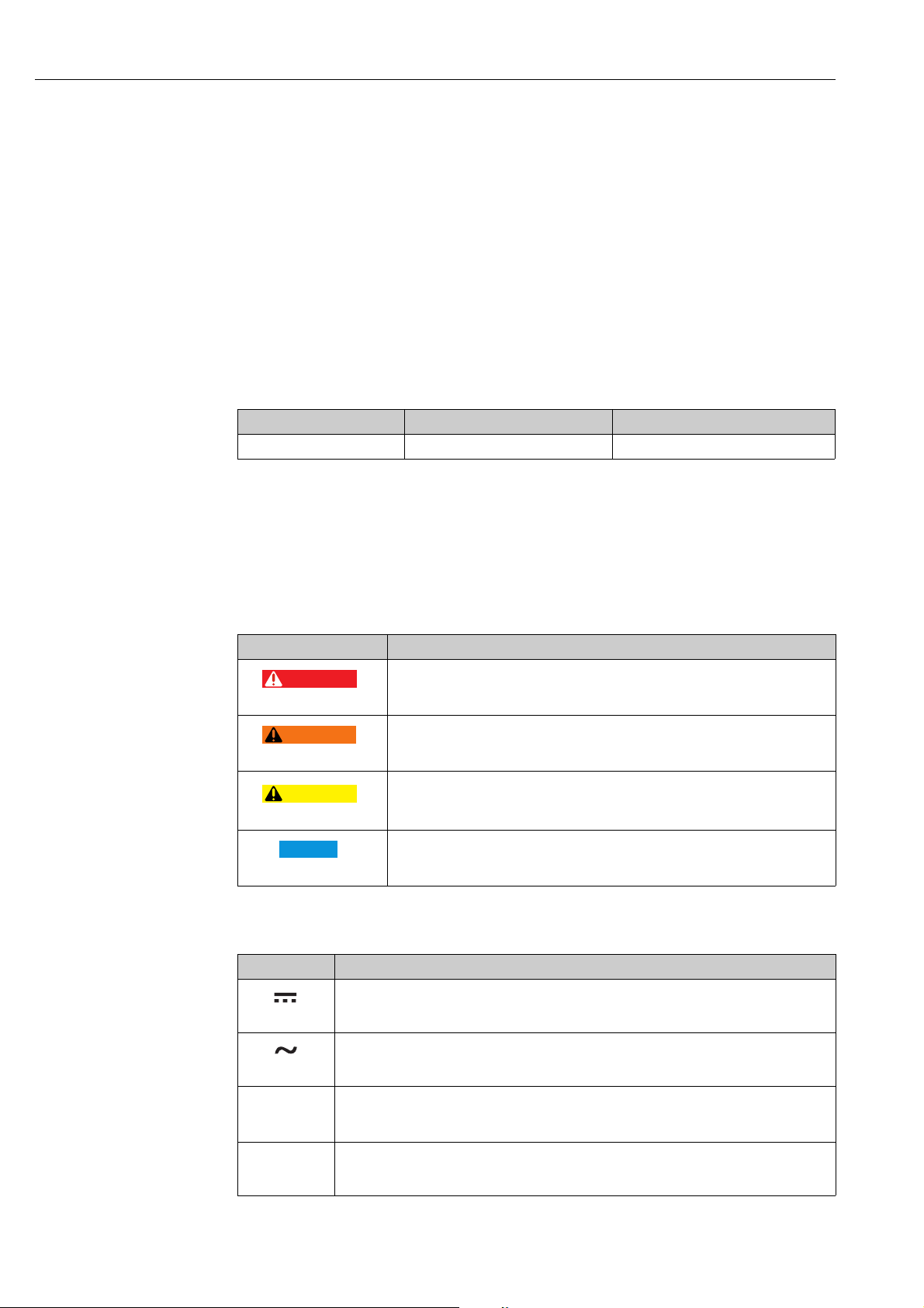
1.3.1 Used symbols
Safety symbols
Symbol Meaning
DANGER!
A0011189-EN
A0011190-EN
A0011191-EN
A0011192-EN
Electrical symbols
Symbol Meaning
Direct current
A terminal to which DC voltage is applied or through which direct current flows.
A0011197
Alternating current
A terminal to which alternating voltage is applied or through which alternating current flows.
A0011198
Ground connection
A grounded terminal which, as far as the operator is concerned, is grounded via a grounding
A0011200
system.
Protective ground connection
A terminal which must be connected to ground prior to establishing any other connections.
A0011199
This symbol alerts you to a dangerous situation. Failure to avoid this situation will
result in serious or fatal injury.
WARNING!
This symbol alerts you to a dangerous situation. Failure to avoid this situation can
result in serious or fatal injury.
CAUTION!
This symbol alerts you to a dangerous situation. Failure to avoid this situation can
result in minor or medium injury.
NOTICE!
This symbol contains information on procedures and other facts which do not result
in personal injury.
4 Endress+Hauser
Page 5
Tankvision Gauge Link Document information
1.
2.
3.
1.
2.
3.
-
.
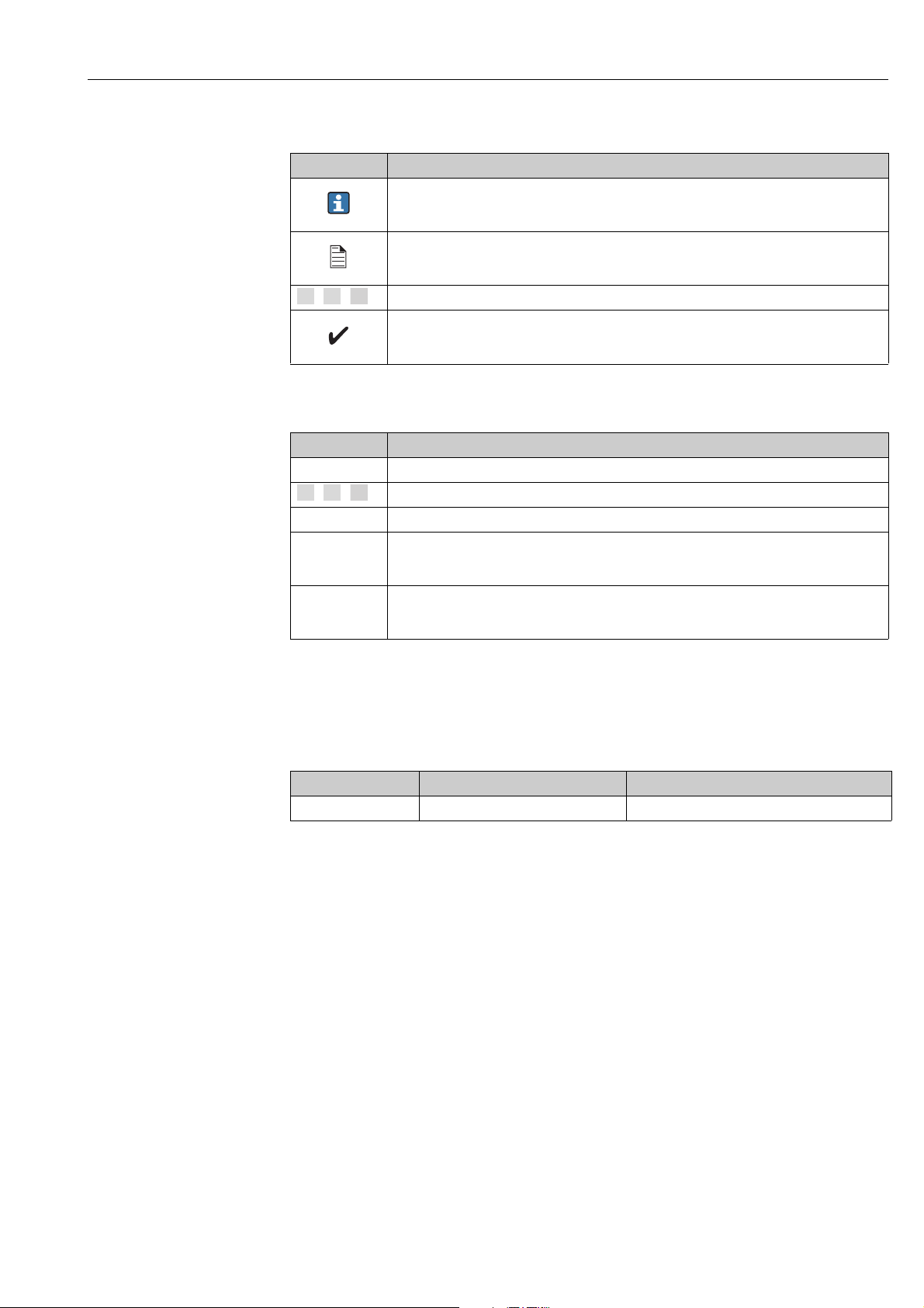
Symbols for certain types of information
Symbol Meaning
Tip
Indicates additional information.
A0011193
Reference to page
Refers to the corresponding page number.
A0011195
, , ... Series of steps
Result of a sequence of actions
A0018373
Symbols in graphics
Symbol Meaning
1, 2, 3 ... Item numbers
, , ... Series of steps
A, B, C ... Views
Hazardous area
Indicates a hazardous area.
A0011187
Indicates a non-hazardous location
Safe area (non-hazardous area)
A0011188
1.4 Documentation
1.4.1 Operating instructions
Document number Instrument Type of Document
BA01334G/00 Tankvision NXA20 Gauge Link Modbus Map Protocol
Endress+Hauser 5
Page 6

Basic safety instructions Tankvision Gauge Link
2 Basic safety instructions
2.1 Requirements for the personnel
The personnel for installation, commissioning, diagnostics and maintenance must fulfill the
following requirements:
• Trained, qualified specialists: must have a relevant qualification for this specific function
and task
• Are authorized by the plant owner/operator
• Are familiar with federal/national regulations
• Before beginning work, the specialist staff must have read and understood the instructions
in the Operating Instructions and supplementary documentation as well as in the
certificates
(depending on the application)
• Following instructions and basic conditions
The operating personnel must fulfill the following requirements:
• Being instructed and authorized according to the requirements of the task by the facility's
owner operator
• Following the instructions in these Operating Instructions
2.2 IT security
We only provide a warranty if the device is installed and used as described in the Operating
Instructions. The device is equipped with security mechanisms to protect it against any
inadvertent changes to the device settings.
IT security measures in line with operators' security standards and designed to provide
additional protection for the device and device data transfer must be implemented by the
operators themselves.
2.3 Designated use
2.3.1 Application
The Tankvision Gauge Link is a tank gauging protocol converter to allow integration of third
party gauging equipment into the Tankvision system. The Tankvision Gauge Link is available
with a range of different field bus interface options. Most field bus interfaces will support
connection of a number of gauges in a “multi-drop” or bus configuration. The number of
gauges which may be configured in the Tankvision Gauge Link is limited to 32 (limited to 15
when used in combination with NXA820), which should be adequate for most typical tank
gauging field busses, however electrical and / or protocol limitations may reduce this
number. The functionality which obtains will be determined by that offered by the connected
gauge(s) and the interface / protocol.
Connection to the host system is via EIA/TIA-485 (formerly RS-485) Modbus. This is
primarily intended for “one-to-one” connection with the Tankvision Tank Scanner or similar
device.
The Tankvision Gauge Link must only be used in “safe” areas where there is no hazard from
the presence of potentially explosive or flammable atmospheres.
The Tankvision Gauge Link has not been assessed in respect of functional safety.
Accordingly it is not intended to be used as a safety critical component or part of a safety
critical system or in the implementation of any safety function.
6 Endress+Hauser
Page 7

Tankvision Gauge Link Basic safety instructions
2.4 Workplace safety
For work on and with the device:
• Wear the required personal protective equipment according to federal/national
regulations.
• Switch off the supply voltage before connecting the device.
2.5 Operational safety
Risk of injury!
• Operate the device in proper technical condition and fail-safe condition only.
• The operator is responsible for interference-free operation of the device.
• In normal operation the Tankvision Gauge Link contains hazardous voltages. Connectors
on the front panel, accessible behind the front cover / door are “touchproof”, but care
must be exercised when carrying out service work with the door open. The unit must not
be operated with any other cover removed.
• If (or it is suspected that) any liquid or conductive object or debris has entered the
enclosure of the Tankvision Gauge Link, the mains supply to the equipment must
immediately be isolated.
Proper operation of the Tankvision Gauge Link is dependent upon correct installation and
configuration. The equipment must be operated and maintained by suitably trained and
competent personnel who are aware of and fully understand the instructions provided
herein.
Conversions to the device
Unauthorized modifications to the device are not permitted and can lead to unforeseeable
dangers
• If, despite this, modifications are required, consult with Endress+Hauser.
Repair
To ensure continued operational safety and reliability,
• Carry out repairs on the device only if they are expressly permitted.
• Observe federal/national regulations pertaining to repair of an electrical device.
• Use original spare parts and accessories from Endress+Hauser only.
The Tankvision Gauge Link contains no user-serviceable parts. Other than the mains supply
fuse, the Tankvision Gauge Link contains no user replaceable parts. Any modification or
repair work must only be performed by the manufacturer or its authorised agents.
2.6 Product safety
The device is designed to meet state-of-the-art safety requirements, has been tested and left
the factory in a condition in which it is safe to operate. The device complies with the
applicable standards and regulations as listed in the EC declaration of conformity and thus
complies with the statutory requirements of the EG directives. Endress+Hauser confirms the
successful testing of the device by affixing to it the CE mark.
Endress+Hauser 7
Page 8
Identification Tankvision Gauge Link
Baud rate: 9600 Baud
Data bits: 8
Parity: none
Stop bits: 1
Flow control: none
90 ... 250 V AC 50/60 Hz 23 VA
MODBUS
IP20
TRL2
250002972-B
Made in Great Britain
Melsonby, DL10 5NY
Tankvision
Order code: NXA20
Ext. ord. cd.:
Ser.-No.: XXXXXXXXXXX
-XXXX/XXX
NXA20-XXXXXXXX
-40°C (-40°F)
£
T60°C (140°F)£
amb
1 2
345
6
8
9
10
11
12
13
14
7
3 Identification
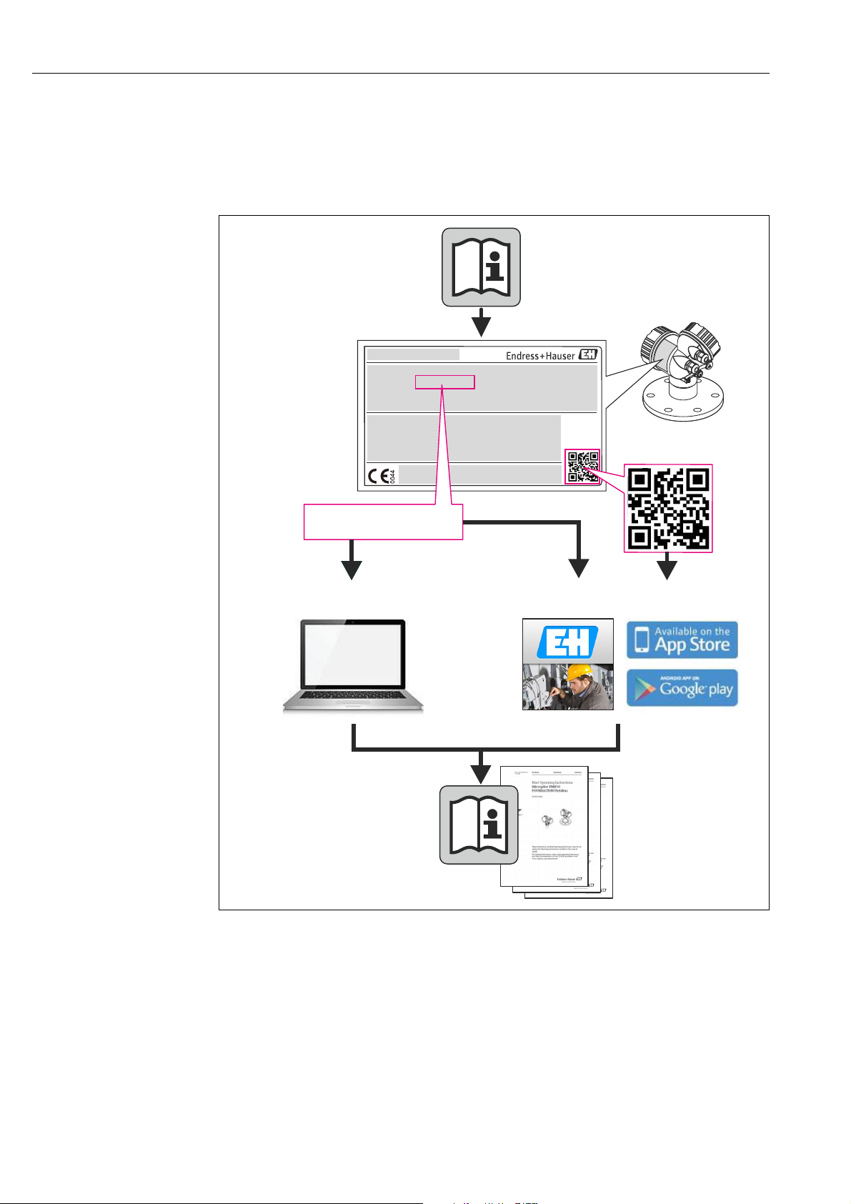
3.1 Product identification
The following options are available for identification of the measuring device:
• Nameplate specifications
• Order code with breakdown of the device features on the delivery note
• Enter serial numbers from nameplates in W@M Device Viewer
(www.endress.com/deviceviewer): All information about the measuring device is
displayed.
For an overview of the technical documentation provided, enter the serial number from the
nameplates in the W@M Device Viewer (www.endress.com/deviceviewer)
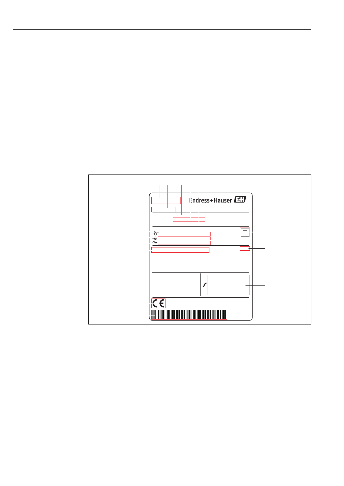
3.2 Nameplate
1 Address of manufacturer
2Device name
3Order code
8 Endress+Hauser
4 Extended order code (Ext. ord. cd.)
5 Serial number (Ser. no.)
6Data Matrix Code
7 Degree of protection
8 Technical data of the Serial Service port
9Barcode
10 CE mark
11 Admissible ambient temperature
12 Type of fieldbus communication (output)
13 Type of fieldbus communication (input)
14 Supply voltage
nameplate_NXA20
Page 9
Tankvision Gauge Link Identification
1.
2.
1.
2.
1.
2.
3.3 Order code and device version
To find out the version of your device, enter the order code indicated on the nameplate
in the search screen at the following address: www.products.endress.com/order-ident
3.4 Device documentation
The information required to retrieve the documentation can be found on the nameplate of
the device.
Technical documentation can also be downloaded from the Download Area of the
Endress+Hauser web site: www.endress.com→ Download. However this technical
documentation applies to a particular instrument family and is not assigned to a
specific device.
3.4.1 W@M Device Viewer
Launch the W@M Device Viewer: www.endress.com/deviceviewer
Enter the serial number (Ser. no.) of the device: see nameplate.
All the associated documentation is displayed.
3.4.2 Endress+Hauser Operations App
The Endress+Hauser Operations App is available both for android smart phones
(Google Play Store) and for iPhones and iPads (App Store).
Via the serial number:
Launch the Endress+Hauser Operations App.
Enter the serial number (Ser. no.) of the device: see nameplate.
All the associated documentation is displayed.
Via the 2-D matrix code (QR code):
Launch the Endress+Hauser Operations App.
Scan the 2-D matrix code (QR code) on the nameplate.
All the associated documentation is displayed.
3.5 Registered trademarks
Microsoft®, Windows® and Internet Explorer
Registered trademarks of the Microsoft Corporation
Modbus
®
Registered trademark of the Modbus-IDA, Hopkinton, MA, USA
®
Java
Registered trademark of Sun Microsystems, Inc.
®
Mozilla
®
Firefox
®
Registered trademark of the Mozilla Foundation
Enraf, Honeywell, Rosemount, Emerson, Saab, L&J, VAREC, GPE are registered trademarks
and trademarks of these organizations and companies.
All other marks are property of their respective owners.
Endress+Hauser 9
Page 10
Technical specification Tankvision Gauge Link
4 Technical specification
4.1 Environmental conditions
The Tankvision Gauge Link enclosure is rated IP20 to BS EN 60529. Further protection
against dust and water/moisture ingress must be provided by the location in which the
Tankvision Gauge Link is installed.
Property Specification
Operating Temperature -40 to +60 °C (-40 to +140 °F)
Storage Temperature -40 to +85 °C (-40 to +185 °F)
Relative humidity max 90 % at +25 °C (+77 °F), non-condensing
4.2 Electrical ratings
Property Specification
Supply voltage 90 to 250 V
Frequency 50 / 60 Hz
Power 23 VA
Overvoltage Category II
AC
Fuse (mains supply) T 400 mA HBC 250V AC, 20 x 5 mm (0,79 x 0,2 in)
10 Endress+Hauser
Page 11
Tankvision Gauge Link Installation
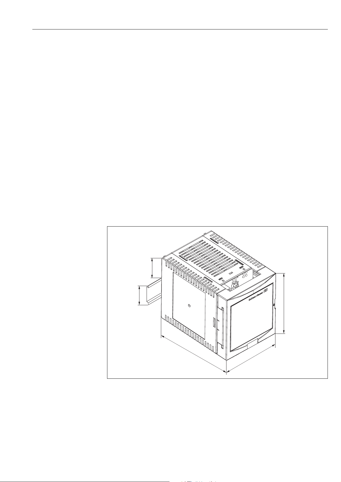
43 (1.7)
35 (1.4)
104 (4.1)
91 (3.6)
140 (5.5)
mm (in)
5Installation
5.1 Mechanical installation/mounting
Prior to installation, visually inspect the Tankvision Gauge Link for any signs of damage.
Confirm that the type label shows the correct field bus interface for the intended application.
The Tankvision Gauge Link must only be installed in a “safe” area where there is no hazard
from the presence of potentially explosive or flammable atmospheres.
The Tankvision Gauge Link must be installed in a cabinet or similar enclosure which provides
protection against dust and water ingress. The location must also provide protection against
moisture or the formation of condensation.
Ensure that the temperatures likely to be encountered at the installation location lie within
the relevant minimum /maximum operating and storage temperature ratings of the
Tankvision Gauge Link.
The Tankvision Gauge Link should not be installed near to high voltage circuits or to cables
feeding motors or other high current loads, or near to contactors, variable frequency drives,
inverters or frequency converters or other switchgear / controlgear which may emit
significant electromagnetic interference.
A clear space of about 50 mm (1.97 in) above and below the Tankvision Gauge Link
enclosure should be allowed for ventilation. A gap of 10 mm (0.39 in) to either side of the
Tankvision Gauge Link will ease mounting and opening of the front cover of the enclosure.
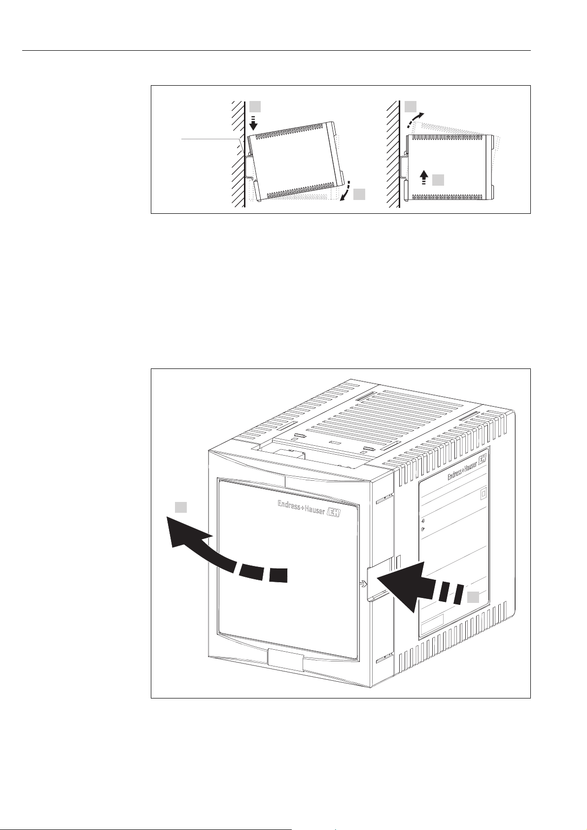
The enclosure of the Tankvision Gauge Link is intended to be mounted onto “top hat” DIN
rail, T35 to BS EN 60715 (or BS 5584 / EN 50022 / DIN 46277-3). The rail should be
mounted on a vertical surface, with the rail running horizontally, so that the Tankvision
Gauge Link connection plate / access cover is to the front and in a readily accessible location.
To attach the Tankvision Gauge Link to the mounting rail, first hook the enclosure over the
top of the rail, then turn downwards until the spring clip on the back of the enclosure latches
onto the lower edge of the mounting rail (fig. A below).
Endress+Hauser 11
GaugeLink_Dimensions
Page 12
Installation Tankvision Gauge Link
A
B
1.
2.
1.
2.
EN 60715
TH 35x7.5/15
(1.4x0.3/0.6)
mm (in)
2.
1.
L00-FMU90xxx-17-00-00-xx-002
A Attaching the instrument to the rail
B Detaching the instrument from the rail
To remove the Tankvision Gauge Link from the mounting rail (fig. B above), first push the
enclosure upwards against the spring clip until the body of the enclosure is released from the
top of the rail, then turn the enclosure forwards, away from the mounting rail.
All electrical connections and controls are available on the front panel of the Tankvision
Gauge Link in the terminal compartment, accessed by opening the front cover / door. This is
hinged at the left and clicks shut. Press on the arrowed area at the right side of the door to
release and open.
12 Endress+Hauser
GaugeLink_Open-Door
Page 13

Tankvision Gauge Link Installation
AB
C
D
E
F
G
H
I
J
GaugeLink_Connections
A Mains supply connector
B Host port status LEDs
C Field port status LEDs
D Diagnostic/Service port connector
E Field port connector
F Host port connector
G Functional earthing terminal
H Weights & Measures sealing switch
I Status relay connector (Not used)
J Mains supply fuse
5.2 Electrical installation
Two-part connectors are used for permanently connected wiring. The free (or cable end)
connector may be unplugged from the panel to assist wiring. Terminals are of the cage clamp
quick connect type; use a screwdriver or similar implement to press down on the orange tab
to open the clamp and allow the stripped wire end to be inserted. The terminals will accept
0.2 to 2.5 mm
insertion of the wire, ensure that no bare conductor is visible, no strands of the conductor
are protruding from the wire entry of the terminal and that the conductor is held securely in
the terminal.
Cables should be routed to pass out through the slot at the bottom of the door. Ensure cables
are not trapped when closing the door.
5.2.1 Mains power supply connections
Mains power supply connection is at the upper left of the front panel.
The Tankvision Gauge Link is double insulated, and thus does not require connection of a
protective earth for safety reasons. An earth terminal is included in the mains supply
connector for EMC purposes. This should be connected to the earth/equipotential conductor
of the supply.
2
(24 to 14 AWG) insulated wires, which should be stripped 10 mm. After
Endress+Hauser 13
Page 14

Installation Tankvision Gauge Link
The Tankvision Gauge Link is regarded as permanently connected equipment. An integral
fuse is provided for overcurrent protection. Protection against electric shock is by double
insulation. It is recommended that the mains supply terminals be connected to the source of
supply by means of an approved flexible cord/cable.
The supply for the Tankvision Gauge Link should be taken from a circuit breaker or switch/
fuse combination to provide electrical isolation external to the Tankvision Gauge Link and
overcurrent protection for the supply cable. This means of isolation should be clearly labelled
as to its function and should be located within easy reach of the Tankvision Gauge Link and
be easy to operate.
5.2.2 Functional earthing terminal
A functional earthing terminal is provided at the lower right of the front panel. This terminal
is used for non-safety earthing of the electronic interface circuits of the Tankvision Gauge
Link, e.g. for EMC purposes.
The functional earthing terminal is electrically separate from and not connected to the earth
terminal of the mains power supply connector.
The functional earthing terminal should be connected to the plant equipotential “ground”
using wire of 4mm
2
(12 AWG) or larger section, with a resistance less than one Ohm.
5.2.3 Status relay connections
The status relay connection at the lower left of the front panel is not used by the Tankvision
Gauge Link. No connection should be made to these terminals.
5.2.4 Host port connections
Host port connection is towards the centre of the front panel. The Modbus host port uses
EIA/TIA-485 (RS-485) “two wire” interface. This provides the “A” / “B” data signal lines and
the “C” common connection.
Note that the polarity of the “A” / “B” data signals is in accordance with the EIA/TIA-485
standard. Many third party devices with “RS-485” interfaces have the sense of the “A” / “B”
lines reversed. When connecting to such devices, it may be necessary to “cross” the “A” and
“B” connections between the devices to obtain the correct signal polarity.
The “S” terminal is provided for connection of the cable screen. This terminal is internally
connected to the functional earthing terminal of the Tankvision Gauge Link (at lower right
of front panel).
Bus termination and biasing are controlled by software selectable settings in the Tankvision
Gauge Link. By default, these are enabled for point-to-point links or the devices in a multidrop network that are at the outer “ends” of the cable. If the Tankvision Gauge Link is part
of a multi-drop network and is not the “end” device on the cable, the termination and biasing
may be disabled. For details of these settings, → ä 18.
The host RS485 connection offers transient overvoltage protection compatible with RS485
signal level.
5.2.5 Field port connections
Field port connection is towards the right of the front panel. The connections will depend
upon the interface.
For Enraf Bi-Phase Mark and “SAAB” Rosemount TRL/2, the fieldbus uses a two wire
connection. The polarity of the connection is not important.
The “S” terminal is provided for connection of the cable screen. This terminal is internally
connected to the functional earthing terminal of the Tankvision Gauge Link (at lower right
of front panel).
Both the Enraf Bi-Phase Mark and SAAB Rosemount TRL/2 fieldbuses are galvanically
isolated and offer over voltage protection commensurate with the original gauge
manufacturers’ equipment.
The Tankvision Gauge Link will be supplied as two different versions, one supporting the
Enraf Protocol and the other supporting the SAAB Rosemount TRL/2 protocol.
14 Endress+Hauser
Page 15

Tankvision Gauge Link Installation
PC
TVGL
= R
= O
1
2
3
4
5
6
7
8
9
1
2
3
4
5
6
7
8
9
5.2.6 Diagnostic/service port connections
The diagnostic / service port generally remains unconnected during normal operation of the
Tankvision Gauge Link. The port has a 9 way “D” type socket connector. A suitable cable with
mating plug will be required for local connection of a service laptop PC or similar.
A “standard” serial port, a 9 way fully wired plug – socket cable will be required. The cable
should be wired pin-to-pin, i.e. 1-1, 2-2, 3-3, … 9-9. Proprietary cables will generally have
all pins wired, though only pins 2, 3, 4, 5 and 7 are actually used. Cable length should not
exceed 2 metres (6,6 ft).
Diagnostic-service_po rt_connections
PC Service laptop PC or similar
TVGL Tanvision Gauge Link
RRequired connection
O Optional connection
Note that in the case of Tankvision Gauge Links on a multi-dropped network, the
service port provides local access to the individual Tankvision Gauge Link only. It is not
possible to communicate with other Tankvision Gauge Links on the network through
this service port.
5.2.7 Internal jumper links
The Print circuit boards within the plastic enclosure of the Tankvision Gauge Link are fitted
with Jumper links, all the jumpers don’t need to be accessed apart from one jumper link.
LK_TS on the BPM module which only needs to be fitted if the field bus baud rate is 2400.
Module Jumper link Use
TRL/2 module LK_P link Used to feed 5vdc supply to board. (default:- open)
Endress+Hauser 15
Page 16

Installation Tankvision Gauge Link
Module Jumper link Use
LK_P link Used to feed 5vdc supply to board. (default:- open)
LK_TS link Fitted for 2400 baud rate. (default:- open)
BPM module
Main Processor
module
Gain can be achieved using LK_G links (gain is described in detail further in the manual)
A link Gain control (bit 0) (default:- open)
B link Gain control (bit 1) (default:- open)
C link Gain control (bit 2) (default:- open)
LK_SG RS485 signal ground. (default:- closed)
ISP Firmware update control (default:- open)
RST Firmware update control (default:- open)
JTAG Debug control (default:- open)
16 Endress+Hauser
Page 17

Tankvision Gauge Link Controls and indicators
6 Controls and indicators
6.1 Reset
A small pushbutton switch is provided to allow the user to reset the Tankvision Gauge Link
without the need to cycle the power. The switch is recessed to prevent inadvertent operation.
A pointed object such as a pen may be used to operate the reset switch.
When the Tankvision Gauge Link is reset, the red FAULT ( ) LED will flash once while the
unit carries out software initialisation. If this LED flashes repeatedly after power up then this
indicates a fault and will need to be investigated.
This reset button behaves the same as turning the Tankvision Gauge Link off and back on
again.
6.2 Weights & measures seal
This switch is used to disable any configuration through the Modbus port and the
engineering port, such as hyper-terminal. When this switch is set, any attempted
configuration changes via Modbus will result in timeouts for the host via hyper-terminal and
the following message will appear: ’config disabled’.
6.3 Power
The Tankvision Gauge Link has two POWER ( ) LEDs, one for the main processor and one
for the field bus interface. The main processor LED is green and the field bus LED is yellow.
These should both be lit during normal operation. A flashing or unlit POWER LED indicates
the presence of a power supply fault.
6.4 Transmit/receive
The host port and field bus interface port both have yellow TRANSMIT ( ) and RECEIVE
( ) LEDs. These flash to indicate activity on the respective communication port data lines.
Note that the TRANSMIT / RECEIVE LEDs indicate only electrical activity on the data
lines, but do not give any indication as to the validity of the data.
6.5 Communications
A yellow COMMUNICATIONS ( ) LED is provided for the field bus interface port. This
flashes to indicate that a valid query – response cycle has been performed by the Tankvision
Gauge Link and that the response from the gauge / field device has been understood by the
Tankvision Gauge Link.
Note that the COMMUNICATIONS LED indicates that the response received was
correctly framed according to the field bus protocol and was thus able to be accepted
and decoded by the Tankvision Gauge Link. It does not give any indication as to the
meaning of the data contained within the response. This yellow LED does not flash
when an engineering software tool is connected to the Tankvision Gauge Link, such as
Ensite.
Endress+Hauser 17
Page 18

Operation Tankvision Gauge Link
7Operation
7.1 Configuration
7.1.1 Connecting to the diagnostic/service port
Connect a laptop PC with a terminal emulation program (e.g. Hyperterminal) to the service
port using a straight-through “null modem” cable.
Set the terminal emulation program to the following communications settings:
Parameter Setting
Baud rate 9600 Baud
Data bits 8
Parity none
Stop bits 1
Flow control none
When the ‘hyper-terminal’ terminal emulation programs are not available, for example
windows 7 is being used, a program such as Tera Term can be used. This program has been
tested, free and is open source.
If the PC doesn’t have a serial port and USB-RS232 can be used. A recommend USB-RS232
is the ULinx USO9ML2DR-2 converter.
7.1.2 Configuration using a terminal emulation program
Using this configuration only allows the Tankvision Gauge Link to be configured,
configuration of Honeywell Enraf and Emerson SAAB gauges must be done separately by a
competent engineer.
Once the Tankvision Gauge Link has been connected the diagnostic port and the terminal
emulation program has been set up, the Tankvision Gauge Link can be powered up. When
the Tankvision Gauge Link is powered up a message is printed and is similar to the message
shown below.
NVRAM STATUS- GOOD
P0264
VERSION – V1-0-0
CHECKSUM – 726E9AE7
FIELD - GPU
MODE - TERMINAL
HTS - 9600
FTS - 1200
HPA - NONE
GPU GAIN – 0
RS485 +VE BIAS - OFF
RS485 -VE BIAS – OFF
RS485 TERM - OFF
The data shown above gives general status and information on the basic configuration, such
as the status of none volatile (flash) memory, the project number of this model and the
firmware version number.
A checksum is also created when the Tankvision Gauge Link is powered up, this number can
be used to confirm the validity of the firmware.
The mode is the terminal emulation mode on the RS232 port.
18 Endress+Hauser
Page 19

Tankvision Gauge Link Operation
The type of Field driver is also displayed which will be either GPU (Honeywell Enraf protocol)
or TRL (Emerson protocol). The Host baud rate (HTS), Field baud rate (FTS) and Host parity
(HPA) are also displayed.
The GPU gain is displayed, this gain will only take affect if the fieldbus is GPU. The
termination and bias resistors are also shown if they are enabled or not.
The above information can be displayed by typing in the INFO(return) command.
7.1.3 Typing and entering a command
Entering a configuration command into Tankvision Gauge Link is done by simply typing the
text into the terminal emulation software and pressing return at the end of the command.
E.g. to print general status and information type: "INFO(return)".
This command will print the information shown in the above section.
After most valid commands an ‘OK’ message will be printed. If an ‘INVALID COMMAND’ or
‘OUT OF RANGE’ message is printed, then re-type the command or investigate the ‘out of
range’ message.
All valid commands are saved in Tankvision Gauge Link flash memory, so when the unit is
powered down and back up the configuration will remain.
7.1.4 Commands
INFO(return)
This command prints the information shown in the above section.
FTS=XXXX(return)
Where XXXX is a 4 digit number.
This command sets the field bus baud rate. If the field driver selected was a TRL driver, then
this command will not have any effect on the Field bus baud rate, because the TRL/2 field
bus is always set to 4800 baud. If the Field driver selected is a GPU driver then there is a
choice of 2 baud rates, 1200 and 2400 baud.
When setting the BPM baud rate to 2400 the jumper link (LK_TS) on the BPM
communication needs to be fitted.
To configure the GPU field bus with a 1200 baud rate, type: FTS=1200(return)
To configure the GPU field bus with a 2400 baud rate, type: FTS=2400(return)
Any other baud rate and an ‘INVALID COMMAND’ message will be printed.
HTS=XXXX(return)
Where XXXX is a 4 digit number.
This command sets the host RS485 field bus baud rate. There are a range of different baud
rates which this command supports, see below the baud rates with the command to set the
baud rate.
Baud rate Command
1200 HTS=1200(return)
2400 HTS=2400(return)
4800 HTS=4800(return)
9600 HTS=9600(return)
Endress+Hauser 19
Page 20

Operation Tankvision Gauge Link
Baud rate Command
19200 HTS=1920(return)
Any other baud rate and an ‘INVALID COMMAND’ message will be printed.
HPA=X(return)
Where X is represents the parity.
The Host field bus can be configured to support 3 different parities. To configure the parities
is shown below:
Parity Command
None HPA=N(return)
Even HPA=E(return)
Odd HPA=O(return)
Any other letter typed and an ‘INVALID COMMAND’ message will be printed.
GPUGAIN=X(return)
This command is only used for Enraf Gauges. This command increases the received data
sensitivity. If the communication is poor and the BPM cabling is long, by increasing this value
the communication should improve.
Where X represents a number between 0 and 7.
0 is the lowest gain and 7 is the highest gain.
For example for the GPU BPM field bus to have a gain of 7, type in the following command:
GPUGAIN=7(return)
RS485+=X(return)
RS485-=X(return)
Where X is represents Y (yes) or N (no).
These commands allow the user to enable the 910R bias resistors to pull the A and B lines
to +5V and 0 volts. This is sometimes referred to as “fail-safe” biassing mode.
Generally these are set to ON when the RS485 comms is point to point and OFF when devices
are multi-dropped on the RS485 comms.
To enable the bias resistors type:
RS485+=Y(return) and RS485-=Y(return)
To disable the bias resistors type:
RS485+=N(return) and RS485-=N(return)
Any other letter typed and an ‘INVALID COMMAND’ message will be printed.
RS485T=X(return)
Where X is represents Y (yes) or N (no).
This command allows the user to enable the 120R terminator resistor between the A and B
lines.
To enable the terminator resistor type: RS485T=Y(return)
To disable the terminator resistor type: RS485T=N(return)
20 Endress+Hauser
Page 21

Tankvision Gauge Link Operation
Generally this is set to ON when Tankvision Gauge Link is at the end of a RS485 multi-drop
line.
Any other letter typed and an ‘INVALID COMMAND’ message will be printed.
CONFIG(return)
This command enables gauge address’s / registers / functions to be written directly to the
modbus holding registers which hold the gauge parameter address’s/registers. Please refer
to document TankVisionFieldLinkModbusMapV1-3-1.
Once this command has been entered values can then be written directly to the holding
registers, using the below command.
Z=X(return) or
Z=XX(return) or
Z=XXX(return) or
ZZ=X(return) or
ZZ=XX(return) or
ZZ=XXX(return) or
ZZZ=X(return) or
ZZZ=XX(return) or
ZZZ=XXX(return) or
ZZZZ=X(return) or
ZZZZ=XX(return) or
ZZZZ=XXX(return)
Where Z represents the modbus holding register and X represents the value to be put into
this holding register.
After every command, enter the value into the holding register, the cursor in the terminal
emulation program will go to the start of the next line and wait for another value to be
entered into the holding register. If no more values are to be entered press (return) and the
message ‘DOWNLOAD COMPLETE’ message will be printed.
For example:
Two gauges are required to be polled by the Tankvision Gauge Link, these gauges are an 873
radar gauge and an 854 servo gauge. Level, temperature and temperature elements are
required from both of the gauges. The 873 gauge also requires a live water value to be read
from it. The 873 gauge has an address of 1 and the 854 gauge has an address of 15.
Type the following bold letters to enter values into the modbus holding registers to poll for
the above parameters.
Enter Result
CONFIG(return) Enable configuration
0=1(return) Level address = 1
100=1(return) Temp address = 1
200=1(return) Element temps address = 1
300=1(return) Water address = 1
1100=82(return) Gauge type is a radar (82)
1=15(return) Level address = 15
101=15(return) Temp address = 15
201=15(return) Temp elements address = 15
1101=83(return) Gauge type is a servo (83)
(return)
Endress+Hauser 21
Page 22

Operation Tankvision Gauge Link
The numbers 78, 82 and 83 in Modbus holding register 1100 – 1131 represent:
78 = decimal value for ascii ‘N’ (Where N = NRF590)
82 = decimal value for ascii ‘R’ (Where N = RADAR)
83 = decimal value for ascii ‘S’ (Where N = SERVO)
When setting a value of 82 in holding registers 1100 – 1131 causes the Tankvision Gauge
Link to poll for the ZQR command, which is the radar status register.
When setting a value of 83 in holding registers 1100 – 1131 causes the Tankvision Gauge
Link to poll for the ZQS command, which is the servo status register.
When setting a value of 78 in holding registers 1100 – 1131 causes the Tankvision Gauge
Link to not poll for any status registers and it will pick its status value from the ‘B’ record.
If holding registers 1100 – 1131 are set to anything other than 78, 82 and 83 then the
status of the gauge will be picked up from the ‘B’ record and ZQR and ZQS will NOT be polled
for.
DEVICES(return)
The devices and configuration parameters for the gauges which have been configured can be
viewed at any time. This command allows you to look at the Modbus holding registers.
The data displayed lists the Modbus holding registers in columns of 100 registers. The first
block to the left lists all the level addresses configured, the second block lists the temperature
addresses configured, these blocks are the blocks of registers detailed in the Tankvision
Gauge Link Modbus Map document. It can be seen at the top of each column shows which
block of 100 registers is detailed. Down the left side the block register is incremented.
The example print out shows the configuration done in the above example:
DEVICES
0000 0100 0200 0300 0400 0500 0600 0700 0800 0900 1000 1100
+ 00 001 001 001 001 255 255 255 255 255 255 255 082
+ 01 015 015 015 255 255 255 255 255 255 255 255 083
As it can be seen the registers configured in the above example marry up with the data
shown above.
The first, left most block of registers, shows the values of 001 and 015. These are the level
addresses. The second block (0100) show the values of 001 (+00) and 015 (+01) these are
the temperature addresses. This pattern is repeated up to block 1100, where it can be seen
block 1100 (+00) contains the value 82 and block 1100 (+01) contains the value 83.
All the unused registers contain the value 255, which represents values which are out of
range.
When connecting to Enraf gauges holding registers 600 – 631 are reserved and not used.
When connecting to SAAB Rosemount gauges holding registers 200 – 231, 400 – 431, 500
– 531, 600 – 631 and 1100 – 1131 are not used.
All holding registers above 31 to the next 100 in the block are un-used.
The diagram below shows in more detail what each column and row represents.
The below is configures to poll for 3 gauges.
st
1
gauge Gauge address 01, Modbus address 01. Radar (82)
Level (Reg 0000)
Temperature (Reg 0100)
Temp elements (Reg 0200)
Live water (Reg 0300)
22 Endress+Hauser
Page 23

Tankvision Gauge Link Operation
2nd gauge Gauge address 15, Modbus address 15, Servo (83)
Level (Reg 0001)
Temperature (Reg 0101)
Temp elements (Reg 0201)
rd
3
gauge Gauge address 16, Modbus address 16, None Enraf gauge (78)
Level (Reg 0002)
Temperature (Reg 0102)
Temp elements (Reg 0202)
The modbus address is always the same as the level address stored in holding registers 0000
– 0031.
So for example the gauge address to read level for the 1st gauge is address 01 in holding
register 0000.
The gauge address to read temperature elements for the 3rd gauge is address 16 in holding
register 202.
FIRST HOLDING REGISTER → 0000 0100 0200 0300 0400 0500 0600 0700 0800 0900 1000 1100
ADDRESSES IN 1ST HOLDING
REGISTER →
ADDRESSES IN 2ND HOLDING
REGISTER →
ADDRESSES IN 3RD HOLDING
REGISTER →
+ 00 001 001 001 001 255 255 255 255 255 255 255 082
+ 01 015 015 015 255 255 255 255 255 255 255 255 083
+ 02 016 016 016 255 255 255 255 255 255 255 255 078
HOLDING REGISTER INDEX →
LEVEL ADDRESS →
TEMPERATURE ADDRESS →
TEMP ELEMENT ADDRESS →
LIVE WATER ADDRESS →
WATER DIP ADDRESS →
DENSITY ADDRESS →
RESERVED ADDRESS →
VAPOUR TEMP ADDRESS →
BASE PRESSURE (P1) ADDRESS →
LIQUID PRESSURE (P2) ADDRESS →
VAPOUR PRESSURE (P3) ADDRESS →
ALLDEVICES(return)
This command basically does the same command as above, but all 32 registers for each block
are displayed.
This command is useful in troubleshooting, to check if there are no random registers
containing values.
GAUGE TYPE →
BLANKXX(return)
Where XX represents a row of gauge parameters between 0 and 32.
XX must be entered as a 2 digit number. E.g. 3 must be entered as 03.
This command blanks all the parameters for a gauge and defaults all the parameters back to
255. This parameter is used if you require to remove a gauge from the system. All gauges
above this gauge will be automatically shuffled down and fill the space which was originally
blanked.
Endress+Hauser 23
Page 24

Operation Tankvision Gauge Link
For example:
It is required that the second gauge needs to be removed from the system, type the following:
BLANK01(return)
FULLBLANK(return)
This command removes all the gauges and parameters from the Tankvision Gauge Link and
defaults the holding register database back to no gauges in the system.
This command is used if you require to start configuration from a fresh.
ENG=ENSITE(return)
This command allows Honeywell Enraf configuration PC tool, Ensite, to be connected to
Tankvision Gauge Link engineering port and support all the features that the Ensite
software require.
Once the above command has been set, a 4 minute timer is set to allow time for the engineer
to disconnect the terminal emulation software and connect the Ensite software. If no data
has been seen after four minutes on the RS232 port of the Tankvision Gauge Link, the port
will then switch back to its normal mode of operation and allow the terminal emulation
software to be used. Once data has been seen on the RS232 port, the timer will reset and if
no data is then seen for 2 minutes the Tankvision Gauge Link will default back to the
terminal emulation mode.
If the Tankvision Gauge Link is powered down and back up when in Ensite mode, it will
power back up in normal, terminal emulation mode, and will need to be set back to Ensite
mode by using the above command.
If Ensite is not polling for data when in this mode, the Tankvision Gauge Link will then
starting poll for normal data as configured in its database, this allows the Tankvision Gauge
Link to keep the data in its database as live as possible, if Ensite then starts polling for data,
the Tankvision Gauge Link will then switch to tunnelling mode and pass the data through
from Ensite to the gauges on the BPM fieldbus.
The CIU address of the Tankvision Gauge Link is always set to 0 (zero). The baud rate of the
Ensite port can run at either 1200 or 2400, this baud rate is determined by what the Field
bus baud rate is set to using the FTS command. Both the Field bus and Ensite baud rates need
to be the same.
The COMMUNICATIONS LED of the fieldbus module will not light up when Ensite is
tunnelling data, but it will light if the Tankvision Gauge Link polls for valid data. This can be
useful to determine what is driving the BPM field bus, Ensite or the Tankvision Gauge Link.
ENG=ENGAUGE(return)
This command offers all the features that the Ensite mode offers, including the Honeywell
Enraf Flexconn configuration tool.
Disabling, CIU address etc are the same as the Ensite mode.
For optimum ENgauge operation with the TVGL, set ENgauge as follows:
•New site
• Enter the units of the parameters
• Add a device to the comms
• Add a field connector
– Choose smartlink and give it a name
• Select the SmartLink and change its comms parameters
– GPU: 1200, 7, O, 1
– Flexconn: 1200, 8, N, 1
• Add a Tank
24 Endress+Hauser
Page 25

Tankvision Gauge Link Operation
• Add a gauge
• Edit gauge properties
– GPU Gauge address (Example 02)
– FlexConn address (Example 0101)
• Once ENG=ENGAUGE in TVGL scan for boards within the actual gauges and use the
ENgauge commands.
ENG=WINSETUP(return)
This is a similar command to the Ensite and Engauge mode, in that it will drop back after 2
or 4 minutes, if the RS232 port sees no data. When Winsetup is NOT polling for data,
Tankvision Gauge Link will start polling for data until the Winsetup then starts polling for
data. The COMMUNICATIONS LED does not light up when Winsetup polls for data. If the
Tankvision Gauge Link is powered down and back up, the unit will default back to normal,
terminal emulation software. The baud rate for this port when in Winsetup mode is always
set to 4800 and no other baud rate can be used.
DEBUG(return)
This command is used to print the data transmitted and received on the Field bus port. This
feature can be useful when commissioning a system. To cancel the debug mode, press the
‘return’ key a few times or power the Tankvision Gauge Link down and back up.
If the Field bus port is a BPM port, then the data printed will be the raw ASCII data, generally
the transmitted and received data will be printed on the same line per gauge, a new line will
be printed for a different gauge.
If the Field port is a TRL/2 port, then the data printed will be the raw decimal data. If a long
message is received, then serial port may not be able to handle all the data so quickly, so the
received data can be shorted, so only the address, function and CRC is viewed, all the rest of
the viewed data will be replaced with a #. To set this command type S(return) when in debug
mode. This feature is only supported for the TRL/2 field bus mode.
7.1.5 Quick list of commands
INFO(return)
FTS=XXXX(return)
HTS=XXXX(return)
HPA=X(return)
GPUGAIN=X(return)
CONFIG(return)
ZZZZ=XXX(return)
DEVICES(return)
ALLDEVICES(return)
BLANKX(return)
FULLBLANK(return)
ENG=ZZZZZ(return)
DEBUG(return)
S(return)
Where X and Z represent letters or numbers.
7.1.6 Configuration practices
Configuring the Tankvision Gauge Link using terminal emulation software is straight
forward to do but a few practices need to be carried out.
When configuring the Tankvision Gauge Link to communicate with Honeywell Enraf, the
type of gauge must be setup in the 1100 block of holding registers, if the type of gauge isn’t
configured, the Tankvision Gauge Link will treat the gauge as a basic Honeywell Enraf 811
gauge.
No type of gauge is required to be configured if connection to Emerson SAAB gauges.
Endress+Hauser 25
Page 26

Operation Tankvision Gauge Link
When adding gauges to the Tankvision Gauge Link it is important that the gauges are added
in consecutive order, otherwise the Tankvision Gauge Link will only poll for the first
addresses until it reaches a level holding register which contains 255, then it will go back
and repeat polling for the first gauges.
For example:
If level and temperature are required from 6 off 854 Honeywell Enraf gauges, having
addresses 01, 02, 03, 04, 05 and 06 respectively, then it is advised that configuration to be
done as follows:
Enter Result
CONFIG(return) Enable configuration
0=1(return) Level address = 1
100=1(return) Temp address = 1
1100=83(return) Gauge type is a servo (83)
1=2(return) Level address = 2
101=2(return) Temp address = 2
1101=83(return) Gauge type is a servo (83)
2=3(return) Level address = 3
102=3(return) Temp address = 3
1102=83(return) Gauge type is a servo (83)
3=4(return) Level address = 4
103=4(return) Temp address = 4
1103=83(return) Gauge type is a servo (83)
4=5(return) Level address = 5
104=5(return) Temp address = 5
1104=83(return) Gauge type is a servo (83)
5=6(return) Level address = 6
105=6(return) Temp address = 6
1105=83(return) Gauge type is a servo (83)
(return)
If the above was configured but the last gauge with address 6 was mapped to as follows:
Enter Result
8=6(return) Level address = 6
108=6(return) Temp address = 6
1108=83(return) Gauge type is a servo (83)
This gauge with address 6 will not be polled for because it is not directly preceeding the
gauge before it.
Each parameter can have a different address within the modbus holding registers. The
reason for this is that different parameters can come from different devices with different
addresses. This allows data from different addresses to be mapped to the group of input
registers, where the address of the input registers is derived from the level address of the
device.
26 Endress+Hauser
Page 27

Tankvision Gauge Link Operation
For example:
If a system requires a level from an Enraf 854 (address 1) and average temperature and
elements from an 864 (address 11) then configuration can be done as shown below:
Enter Result
CONFIG(return) Enable configuration
0=1(return) Level address = 1
100=11(return) Temp address = 11
200=11(return) Temp elements address = 11
1100=83(return) Gauge type is a servo (83)
(return)
All the data will be picked up from input registers with an address of 1.
If a system requires a level from an Emerson REX (address 1) and average temperature and
elements from a DAU (address 101) then configuration can be done as shown below:
Enter Result
CONFIG(return) Enable configuration
0=1(return) Level address = 1
100=101(return) Temp address = 101
(return)
All the data will be picked up from input registers with an address of 1.
As it can be seen, the element temperature is automatically mapped to address 101 because
the elements is associated with average temperature. No gauge type is required for the TRL/
2 fieldbus.
7.1.7 Honeywell Enraf Fieldbus
Configuration of the Tankvision Gauge Link to poll for Honeywell Enraf gauges has been
covered in the above examples and explanations. Configuring the Tankvision Gauge Link to
poll for Emerson SAAB gauges is slightly different.
7.1.8 Emerson SAAB Fieldbus
Configuration of the Tankvision Gauge Link to poll for level and temperature from Emerson
SAAB devices is the same as configuring Honeywell Enraf devices, in that the level address
comes from holding registers 0 – 31 and temperature address comes from holding registers
100 -131.
The temperature elements address automatically comes from the address in holding
registers 100 – 131, so there is no need to configure any addresses in holding registers 200
– 231.
Live water, Vapour temperature, Base pressure, Liquid pressure and vapour temperature can
be mapped back to the input registers with an address of the level address. The TRL/2
protocol doesn’t specifically have a register for the above parameters, but the Emerson REX
gauge has analogue and HART inputs which can be mapped and scaled within the Emerson
REX gauge. These inputs can then be picked up on the TRL/2 protocol and mapped within
the Tankvision Gauge Link.
The Tankvision Gauge Link will not scale the above parameters which come back on the TRL/
2 protocol, this must be done in the gauge and this is the usual practice when working with
Emerson equipment.
Endress+Hauser 27
Page 28

Operation Tankvision Gauge Link
The below inputs to the Emerson REX gauge are mapped to the TRL/2 registers. These will
only be picked up from the gauge with the address in holding registers 0 -31. These will not
be picked up from a DAU.
Emerson REX input TRL/2 Register
Analogue input current 1 06
Analogue input current 2 07
Analogue input current 3 08
Analogue input 1 30
Analogue input 2 32
HART Input 3 36
HART Input 2 38
HART Input 1 40
For example:
A system has a REX gauge with an address of 2 and a DAU for temperature of 102. Live
water and vapour temperature is also required, these will be mapped to Analogue input
current 1 and HART input 1 respectively in the REX gauge. Configure the Tankvision Gauge
Link as follows:
Enter Result
CONFIG(return) Enable configuration
0=2(return) Level address = 2
100=102(return) Temp address = 102
300=06(return) Water from register 06 with address 2
700=40(return) Vapour temp from register 40 with address 2
(return)
7.1.9 Worked examples
Example 1
A system requires to be connected to 5 off Honeywell Enraf gauges. GPU baud rate is 1200.
The modbus interface is 9600, None, 8, 1.
• Gauge address = 1, needs level and temp. Gauge type 854.
• Gauge address = 2, needs level and temp. Gauge type 873.
• Gauge address = 5, needs level, temp, temp elements, water dip and density. Gauge type
854.
• Gauge address = 9, needs level. Temp and its elements are from an 864 with address 19.
Gauge type 873.
• Gauge address = 20, needs level and temp. Gauge type is an Enraf emulation coming from
a none Enraf gauge.
Ensure the Tankvision Gauge Link is the Enraf version.
Enter Result
FTS=1200(return) Enable
HTS=9600(return) Enable
HPA=N(return) Enable
28 Endress+Hauser
Page 29

Tankvision Gauge Link Operation
Enter Result
CONFIG(return) Enable configuration
0=1(return) Level address = 1 (modbus address = 1)
100=1(return) Temp address = 1
1100=83(return) Gauge type is a servo (83)
1=2(return) Level address = 2 (modbus address = 2)
101=2(return) Temp address = 2
1101=82(return) Gauge type is a radar (82)
2=5(return) Level address = 5 (modbus address = 5)
102=5(return) Temp address = 5
202=5(return) Element temp address = 5
402=5(return) Water dip address = 5
502=5(return) Density = 5
1102=83(return) Gauge type is a servo (83)
3=9(return) Level address = 9 (modbus address = 9)
103=19(return) Temp address = 19
203=19(return) Temp address = 19
1103=82(return) Gauge type is a servo (82)
4=20(return) Level address = 20 (modbus address = 20)
104=20(return) Temp address = 20
1104=78(return) Gauge type is basic (78)
(return)
Once the above has been done type in DEVICES(return) to confirm your configuration is
correct.
Example 2
A system requires to be connected to 5 off Emerson gauges. The modbus interface is 19200,
None, 8, 1.
• Gauge address = 1, needs level and temp.
• Gauge address = 2, needs level and temp.
• Gauge address = 7, needs level, temp, temp elements, live water from gauge register
analogue input current 2 and product pressure from gauge register HART input 2.
• Gauge address = 8, needs level. Temp and its elements is from a DAU with address 108.
• Gauge address = 21, needs level and temp. Gauge type is an TRL emulation coming from
a none Emerson gauge.
Ensure the Tankvision Gauge Link is the TRL/2 version.
Enter Result
HTS=1920(return)
HPA=N(return)
CONFIG(return) Enable configuration
Endress+Hauser 29
Page 30

Operation Tankvision Gauge Link
Enter Result
0=1(return) Level address = 1 (modbus address = 1)
100=1(return) Temp address = 1
1=2(return) Level address = 2 (modbus address = 2)
101=2(return) Temp address = 2
2=7(return) Level address = 7 (modbus address = 7)
102=7(return) Temp address = 7
302=7(return) Water register 07 from address 7
902=38(return) Product pressure register 38 from address 7
3=8(return) Level address = 8 (modbus address = 8)
103=108(return) Temp address = 108
4=21(return) Level address = 21 (modbus address = 21)
104=21(return) Temp address = 21
(return)
Once the above has been done type in DEVICES(return) to confirm your configuration is
correct.
Example 3
A system requires to be connected to 6 of NRF590 gauges (emulating Enraf GPU) with
address 01 – 06.
Level and temperature are required from all gauges.
Host baud rate is 9600, with a parity of none. BPM baud rate is 1200.
Enter Result
FTS=1200(return)
HTS=9600(return)
HPA=N(return)
CONFIG(return) Enable configuration
0=1(return) Level address = 1 (modbus address = 1)
100=1(return) Temp address = 1
1100=78(return) Gauge type is a NRF590 (78)
1=2(return) Level address = 2 (modbus address = 2)
101=2(return) Temp address = 2
1101=78(return) Gauge type is a NRF590 (78)
2=3(return) Level address = 3 (modbus address = 3)
102=3(return) Temp address = 3
1102=78(return) Gauge type is a NRF590 (78)
30 Endress+Hauser
Page 31

Tankvision Gauge Link Operation
Enter Result
3=4(return) Level address = 4 (modbus address = 4)
103=4(return) Temp address = 4
1103=78(return) Gauge type is a NRF590 (78)
4=5(return) Level address = 5 (modbus address = 5)
104=5(return) Temp address = 5
1104=78(return) Gauge type is a NRF590 (78)
5=6(return) Level address = 6 (modbus address = 6)
105=6(return) Temp address = 6
1105=78(return) Gauge type is a NRF590 (78)
(return)
Example 4
A system requires to be connected to 4 of NRF590 gauges (emulating Enraf GPU) with
address 01 – 04.
Level Only is required.
Host baud rate is 9600, with a parity of none. BPM baud rate is 1200.
Enter Result
FTS=1200(return)
HTS=9600(return)
HPA=N(return)
CONFIG(return) Enable configuration
0=1(return) Level address = 1 (modbus address = 1)
1100=78(return) Gauge type is a NRF590 (78)
1=2(return) Level address = 2 (modbus address = 2)
1101=78(return) Gauge type is a NRF590 (78)
2=3(return) Level address = 3 (modbus address = 3)
1102=78(return) Gauge type is a NRF590 (78)
3=4(return) Level address = 4 (modbus address = 4)
1103=78(return) Gauge type is a NRF590 (78)
(return)
Example 5
A system requires to be connected to 4 of 873 gauges and 2 off 854 gauges with address 01
– 06.
Endress+Hauser 31
Page 32

Operation Tankvision Gauge Link
Level and temperature are required from all gauges.
Host baud rate is 9600, with a parity of none. BPM baud rate is 1200.
Enter Result
FTS=1200(return)
HTS=9600(return)
HPA=N(return)
CONFIG(return) Enable configuration
0=1(return) Level address = 1 (modbus address = 1)
100=1(return) Temp address = 1
1100=82(return) Gauge type is a RADAR (82)
1=2(return) Level address = 2 (modbus address = 2)
101=2(return) Temp address = 2
1101=82(return) Gauge type is a RADAR (82)
2=3(return) Level address = 3 (modbus address = 3)
102=3(return) Temp address = 3
1102=82(return) Gauge type is a RADAR (82)
3=4(return) Level address = 4 (modbus address = 4)
103=4(return) Temp address = 4
1103=82(return) Gauge type is a RADAR (82)
4=5(return) Level address = 5 (modbus address = 5)
104=5(return) Temp address = 5
1104=83(return) Gauge type is a SERVO (83)
5=6(return) Level address = 6 (modbus address = 6)
105=6(return) Temp address = 6
1105=83(return) Gauge type is a SERVO (83)
(return)
Example 6
A system requires to be connected to 2 of 873 gauges and 2 off 854 gauges with address 01
– 04.
Level only is requires.
Host baud rate is 9600, with a parity of none. BPM baud rate is 1200.
Enter Result
FTS=1200(return)
HTS=9600(return)
HPA=N(return)
32 Endress+Hauser
Page 33
Tankvision Gauge Link Operation
Enter Result
CONFIG(return) Enable configuration
0=1(return) Level address = 1 (modbus address = 1)
1100=82(return) Gauge type is a RADAR (82)
1=2(return) Level address = 2 (modbus address = 2)
1101=82(return) Gauge type is a RADAR (82)
2=3(return) Level address = 3 (modbus address = 3)
1102=83(return) Gauge type is a SERVO (83)
3=4(return) Level address = 4 (modbus address = 4)
1103=83(return) Gauge type is a SERVO (83)
(return)
Example 7
A system requires to be connected to 5 of SAAB rosemount gauges address 01 - 05.
Level and temperature are required.
Host baud rate is 9600, with a parity of none.
Enter Result
HTS=9600(return)
HPA=N(return)
CONFIG(return) Enable configuration
0=1(return) Level address = 1 (modbus address = 1)
100=1(return) Temp address = 1
1=2(return) Level address = 2 (modbus address = 2)
101=2(return) Temp address = 2
2=3(return) Level address = 3 (modbus address = 3)
102=3(return) Temp address = 3
3=4(return) Level address = 4 (modbus address = 4)
103=4(return) Temp address = 4
4=5(return) Level address = 5 (modbus address = 5)
104=5(return) Temp address = 5
(return)
Endress+Hauser 33
Page 34

Operation Tankvision Gauge Link
Example 8
A system requires to be connected to 4 of SAAB rosemount gauges address 01 - 04
Level only is required.
Host baud rate is 9600, with a parity of none.
Enter Result
HTS=9600(return)
HPA=N(return)
CONFIG(return) Enable configuration
0=1(return) Level address = 1 (modbus address = 1)
1=2(return) Level address = 2 (modbus address = 2)
2=3(return) Level address = 3 (modbus address = 3)
3=4(return) Level address = 4 (modbus address = 4)
(return)
7.1.10 Configuring through the Modbus Map
The holding registers which contain the gauge addresses etc can also be configured through
the RS485 Modbus host port using function code 3 of the Modbus protocol. Writing into
these registers is done using function code 6 or 16.
The purpose of this feature allows gauges to be added or deleted from a system remotely,
which allows host packages which have a configuration tool as part of it’s software suit to do
the configuration. This feature also allows its configuration to be stored remotely and the
configuration to be downloaded to the Tankvision Gauge Link on power up of a whole system
if required.
Refer to the Tankvision Gauge Link Modbus Map document for configuring the Tankvision
Gauge Link through the Modbus interface. The same principles apply when configuration is
done through the terminal emulation program, such as the gauges much be configured in
consecutive order (→ ä 25).
The address when configuring the Tankvision Gauge Link is default 247 or any of the
addresses configured in holding registers 0 -31.
The only parameters which can not be configured through the modbus link are parameters,
such as the engineering mode, field mode, baud rates, parity, GPU gain.
7.2 Operation
The operation of the Tankvision Gauge Link is straight forward, the Modbus interface
complies with the Modbus specification. Refer to the document Tankvision Gauge Link
Modbus Map. In general data from each gauge and auxiliary device is mapped to an address
which is assigned in holding registers 0 – 31. The data will be picked up from the input
registers using function code 4. The Tankvision Gauge Link can support up to 32 Modbus
addresses, so in theory 32 gauges and auxiliary devices can be connected, but in practice the
electrical limitations of the BPM and TRL/2 field bus wouldn’t allow for this.
The Tankvision Gauge Link supports a range of different units, which are detailed in the
Tankvision Gauge Link Modbus Map. The Tankvision Gauge Link reads the units on power
34 Endress+Hauser
Page 35

Tankvision Gauge Link Operation
up from the gauges, it is important that the Modbus host has been configured to calculate
the different units. The Tankvision Gauge Link can support gauges on the same field bus
with different units, but in practice, all the gauges on the field bus would typically have the
same units.
The scan cycle is the level is polled on a frequent basis, temperature is polled for
approximately half to a quarter the level depending on the gauge type. Other parameters are
polled once every cycle. The cycle time is dependent on the number of gauges and
parameters configured.
If a gauge was lost the Tankvision Gauge Link would do a number of polls for that gauge, if
still no gauge was detected, it would set all the registers associated with that gauge to
0xFFFF hex. It would then move on and poll for the rest of the gauges. Depending on the
gauge setup, if an auxiliary device was connected such as a DAU and comms was lost to the
gauge but not DAU, the data from the DAU would still be returned, this would also apply if
comms was lost from the DAU but not the gauge.
If a parameter from the gauge had an error, the last valid reading would be returned to the
Modbus map, but the status bit(s) would be set to indicate an error, the last valid reading can
be useful to know when troubleshooting.
Commands can be issued from the Tankvision Gauge Link, if the gauge supports it, such as
stow, density dip etc.
A range of other data can be read from the gauges as detailed in the Modbus specification
document. These parameters must be setup in the appropriate gauge, such as the high and
low alarms.
The Tankvision Gauge Link has a heartbeat and various information registers, these are
detailed in the Modbus map manual.
Generally the status register offset 21 is used to read the status of the gauge such as ‘is the
gauge doing a water dip?’ etc. The status register for each parameter is generally used to test
whether the parameter is healthy or not.
7.3 Engineering mode
This mode allows, Ensite, Engauge or Winsetup to be connected to the RS232 port and used
to interface directly to the gauges.
When using these tools a trained engineer much be familiar with the tools.
Data, such as level, temp etc, can still be read from the gauges when using the tunnelling
engineering tools, but if the tools are running for long periods of time an update of new date
to the Tankvision Gauge Link may take some time. It is important that the control room must
be made aware that the data from the modbus link may not be live. It is the responsibility of
the engineer to ensure that the data read from the Tankvision Gauge Link may not be live
when using the engineering tools and advise the control room of this.
If the engineering tool stops communicating through the Tankvision Gauge Link for 1
second, then the Tankvision Gauge Link will then start polling for data. As soon as the
engineering tool starts sending data to the gauges, the Tankvision Gauge Link then stops
polling for live data.
The COMMUNICATIONS understood LED will not flash when the engineering tool is passing
data through the Tankvision Gauge Link. This can be useful to determine which device is
polling for data.
Endress+Hauser 35
Page 36
Troubleshooting Tankvision Gauge Link
8Troubleshooting
8.1 Diagnostics
8.1.1 Use of fully wired serial cables
Use the cable as described in previous section and connect to the RS232 port of the
Tankvision Gauge Link and connect the other end to a laptop PC with a terminal emulation
program (e.g. Hyperterminal).
Set the terminal emulation program to the following communications settings:
Parameter Setting
Baud rate 9600 Baud
Data bits 8
Parity none
Stop bits 1
Flow control none
Use the command DEBUG(return) to print the raw GPU (Enraf) or TRL/2 (SAAB) data on
the fieldbus. If the fieldbus is TRL/2 then the command S(return) may be required as the
TRL/2 messages maybe too long so the S Command will Shorten the data printed to hyperterminal.
If for any reason a firmware update is required, links (ISP and RST) within the Tankvision
Gauge Link need to be fitted and the use of flash magic to update the firmware. Details of
firmware updates will be supplied if firmware updates are required in the future.
8.2 Fault finding chart
Symptom Possible cause Remedy
No LED indications:
POWER ( ) LEDs not lit
FAULT ( ) LED lit Internal fault Return unit for repair.
FAULT ( ) LED flashes
repeatedly
Host port RECEIVE ( ) LED
appears to be “permanently” lit,
possibly flickers off for very short
time
Host port RECEIVE ( ) LED does
not flicker / no activity
Mains power failure Investigate and rectify.
Mains supply fuse ruptured Investigate. If no fault evident,
Internal fault Return unit for repair.
Internal fault Return unit for repair.
EIA-485 “A” / “B” data signal lines
“crossed”
No requests from host Investigate and rectify.
Wiring fault between host and
Tankvision Gauge Link
replace fuse with new one of same
rating. If fuse immediately ruptures
or Tankvision Gauge Link does not
operate normally, return unit for
repair.
Swap “A” / “B” connections at host
port connector.
Investigate and rectify.
36 Endress+Hauser
Page 37
Tankvision Gauge Link Troubleshooting
Symptom Possible cause Remedy
Host port RECEIVE ( ) LED
flickers but no activity on
TRANSMIT ( ) LED
Host port RECEIVE ( ) LED
flickers, intermittent or no
TRANSMIT ( ) LED activity
Field port TRANSMIT ( ) LED
flickers but no activity on RECEIVE
() LED
Field port TRANSMIT ( ) LED
flickers, RECEIVE ( ) LED flickers
normally except periodic gaps in
activity at evenly spaced regular
intervals
Field port TRANSMIT ( ) LED
flickers, intermittent or no RECEIVE
( ) LED activity
Field port TRANSMIT ( ) and
RECEIVE ( ) LEDs flicker,
intermittent or no
COMMUNICATIONS ( ) LED
activity
Incorrect configuration:
• wrong communications
parameters (Baud rate, etc.)
• wrong protocol
• wrong Modbus slave address
Garbled communications:
• loose connection
• noise/interference
• Baud rate too high
Incorrect configuration:
•wrong field bus interface
• wrong communications
parameters (Baud rate, etc.)
• wrong protocol
•wrong gauge addresses
Wiring fault between Tankvision
Gauge Link and gauges
Incorrect configuration:
• wrong data parameters
• requesting parameters that are
not supported by the gauge
• one or more wrong gauge
addresses
Garbled communications:
• loose connection
• noise/interference
• Baud rate too high
• excessive bus loading
Investigate and rectify.
Host and Tankvision Gauge Link
must be set to same comms
parameters.
Protocol is Modbus RTU.
Modbus requires 8 data bits for
RTU. Parity is usually “none” (not
needed for RTU)
Check wiring.
Check for sources of noise/
interference.
Try slower Baud rate.
Investigate and rectify.
Tankvision Gauge Link must be set
to same comms parameters as
gauges.
Protocol must suit field bus
interface option.
Investigate and rectify.
Check wiring.
Investigate and rectify.
Tankvision Gauge Link must be set
to only request parameters that are
available from the gauges.
Check for incorrect or conflicting
gauge address.
Check wiring.
Check for sources of noise/
interference.
Try slower Baud rate (subject to
protocol limitations).
Reduce number of gauges on field
bus. (see note)
If the Tankvision Gauge Link is being installed to replace an existing tank gauging host,
it may be possible to verify the prevailing field bus communications conditions before
attempting to install the Tankvision Gauge Link. This will assist in tracing subsequent
communications problems if they relate to incorrect configuration, or poor
communications/intermittent comms failures resulting from field conditions (bus
loading, noise/interference, etc.).
Endress+Hauser 37
Page 38

Maintenance Tankvision Gauge Link
9 Maintenance
The Tankvision Gauge Link normally requires no routine / preventive maintenance other
than periodically checking for signs of the enclosure ventilation slots becoming blocked with
dust, etc.
9.1 Foreign object/liquid ingress
If (or it is suspected that) any liquid or conductive object or debris has entered the enclosure
of the Tankvision Gauge Link, the mains supply to the equipment must immediately be
isolated.
The enclosure is not intended to be opened or dismantled by the user. If possible the foreign
object may be retrieved by dismounting the Tankvision Gauge Link and gently tilting and
shaking the enclosure until the object falls out.
In the case of water ingress, place the Tankvision Gauge Link in a warm location and allow
the enclosure to thoroughly dry out.
Do not reinstall the Tankvision Gauge Link until it is certain that all foreign object / debris
or contamination has been completely removed from the enclosure. On first power-up check
for signs of unusual or incorrect operation, burning smells or smoke emanating from the
enclosure.
If there is any doubt that debris or contamination remains within the Tankvision Gauge Link
enclosure or that the internal parts may have been damaged, the unit should be returned to
the manufacturer or one of its authorised agents for repair.
9.2 Insulation/Hi-Pot testing
The Tankvision Gauge Link undergoes all necessary tests during manufacture. It is not
necessary, and indeed undesirable, to perform routine high voltage insulation testing on the
unit after installation. Repeated high voltage testing may cause degradation of insulation
characteristics which may impair safety.
If it is desired to perform high voltage insulation testing on the electrical installation/cabling
then it is recommended that the mains supply connector is unplugged at the Tankvision
Gauge Link and placed away from the enclosure.
38 Endress+Hauser
Page 39

Tankvision Gauge Link
Index
C
Commands . . . . . . . . . . . . . . . . . . . . . . . . . . . . . . . . . . . . . 19
Quick list . . . . . . . . . . . . . . . . . . . . . . . . . . . . . . . . . . . . 25
Communications . . . . . . . . . . . . . . . . . . . . . . . . . . . . . . . . 17
Configuration . . . . . . . . . . . . . . . . . . . . . . . . . . . . . . . . . . . 18
Configuration practices. . . . . . . . . . . . . . . . . . . . . . . . . . . 25
Configuration using a terminal emulation program . . . 18
Configuring through the Modbus Map . . . . . . . . . . . . . . 34
Connecting to the diagnostic/service port . . . . . . . . . . . 18
Controls and indicators . . . . . . . . . . . . . . . . . . . . . . . . . . . 17
D
Designated use. . . . . . . . . . . . . . . . . . . . . . . . . . . . . . . . . . . . 6
Device version . . . . . . . . . . . . . . . . . . . . . . . . . . . . . . . . . . . . 9
Diagnostic/service port connections . . . . . . . . . . . . . . . . 15
Diagnostics . . . . . . . . . . . . . . . . . . . . . . . . . . . . . . . . . . . . . 36
E
Electrical installation. . . . . . . . . . . . . . . . . . . . . . . . . . . . . 13
Electrical ratings . . . . . . . . . . . . . . . . . . . . . . . . . . . . . . . . 10
Emerson SAAB Fieldbus . . . . . . . . . . . . . . . . . . . . . . . . . . 27
Engineering mode . . . . . . . . . . . . . . . . . . . . . . . . . . . . . . . 35
Environmental conditions . . . . . . . . . . . . . . . . . . . . . . . . 10
F
Fault finding chart. . . . . . . . . . . . . . . . . . . . . . . . . . . . . . . 36
Field port connections. . . . . . . . . . . . . . . . . . . . . . . . . . . . 14
Foreign object/liquid ingress . . . . . . . . . . . . . . . . . . . . . . 38
Functional earthing terminal . . . . . . . . . . . . . . . . . . . . . . 14
R
Reset . . . . . . . . . . . . . . . . . . . . . . . . . . . . . . . . . . . . . . . . . . . 17
S
Safety icons . . . . . . . . . . . . . . . . . . . . . . . . . . . . . . . . . . . . . . 4
Status relay connections. . . . . . . . . . . . . . . . . . . . . . . . . . . 14
Symbols . . . . . . . . . . . . . . . . . . . . . . . . . . . . . . . . . . . . . . . . . 4
T
Technical specification . . . . . . . . . . . . . . . . . . . . . . . . . . . . 10
Trademarks . . . . . . . . . . . . . . . . . . . . . . . . . . . . . . . . . . . . . . 9
Transmit/receive . . . . . . . . . . . . . . . . . . . . . . . . . . . . . . . . . 17
Troubleshooting . . . . . . . . . . . . . . . . . . . . . . . . . . . . . . . . . 36
Typing and entering a command . . . . . . . . . . . . . . . . . . . 19
U
Use of fully wired serial cables . . . . . . . . . . . . . . . . . . . . . 36
W
Weights & measures seal . . . . . . . . . . . . . . . . . . . . . . . . . . 17
Worked examples . . . . . . . . . . . . . . . . . . . . . . . . . . . . . . . . 28
H
Honeywell Enraf Fieldbus. . . . . . . . . . . . . . . . . . . . . . . . . 27
Host port connections . . . . . . . . . . . . . . . . . . . . . . . . . . . . 14
I
Icons . . . . . . . . . . . . . . . . . . . . . . . . . . . . . . . . . . . . . . . . . . . . 4
Installation . . . . . . . . . . . . . . . . . . . . . . . . . . . . . . . . . . . . . 11
Insulation/Hi-Pot testing . . . . . . . . . . . . . . . . . . . . . . . . . 38
Internal jumper links. . . . . . . . . . . . . . . . . . . . . . . . . . . . . 15
IT security . . . . . . . . . . . . . . . . . . . . . . . . . . . . . . . . . . . . . . . . 6
M
Mains power supply connections. . . . . . . . . . . . . . . . . . . 13
Maintenance . . . . . . . . . . . . . . . . . . . . . . . . . . . . . . . . . . . 38
Mechanical installation/mounting . . . . . . . . . . . . . . . . . 11
N
Nameplate . . . . . . . . . . . . . . . . . . . . . . . . . . . . . . . . . . . . . . . 8
O
Operation . . . . . . . . . . . . . . . . . . . . . . . . . . . . . . . . . . . 18, 34
Order code . . . . . . . . . . . . . . . . . . . . . . . . . . . . . . . . . . . . . . . 9
P
Power . . . . . . . . . . . . . . . . . . . . . . . . . . . . . . . . . . . . . . . . . 17
Endress+Hauser 39
Page 40

www.addresses.endress.com
71310503
 Loading...