

Page 1
BA01026G/00/EN/22.19
71435462
2019-04-26
Products Solutions Services
Operating Instructions
Prothermo NMT539
Average temperature device
Device functions
Page 2
Prothermo NMT539
Order code:
Ext. ord. cd.:
Ser. no.:
www.endress.com/deviceviewer
Endress+Hauser
Operations App
XXXXXXXXXXXX
XXXXX-XXXXXX
XXX.XXXX.XX
Serial number
1.
3.
2.
A0023555
2 Endress+Hauser
Page 3

Prothermo NMT539 Table of contents
Table of contents
1 About this document ................ 4
1.1 Document function ..................... 4
1.2 Symbol .............................. 4
1.3 Documentation ........................ 7
1.4 Registered trademarks ................... 7
2 Basic safety instructions ............ 8
2.1 Requirements for personnel ............... 8
2.2 Designated use ........................ 8
2.3 Workplace safety ....................... 8
2.4 Operational safety ...................... 9
2.5 Product safety ......................... 9
3 Product description ................ 10
3.1 Product design ........................ 10
3.2 Technical data ........................ 10
3.3 Description of functions ................. 13
4 Adjustment and settings ........... 18
4.1 Local HART connection ................. 18
4.2 Device configuration: NRF590 ............ 19
4.3 Device configuration: NMS5/NMS7 ........ 19
4.4 Configuring NMT539 with NMS8x/NMR8x/
NRF81 ............................. 21
5 Operation ......................... 28
5.1 HART device codes ..................... 28
5.2 Device data .......................... 28
5.3 Temperature measurement .............. 28
5.4 WB measurement ..................... 42
5.5 Temperature + water bottom measurement .. 47
5.6 Exclusion of WB temperature elements from
average temperature calculation ........... 47
5.7 WB (water bottom) level input from host .... 48
5.8 Temperature element near the tank bottom .. 49
5.9 Write-protection switch (write-protection
plug) ............................... 51
5.10 Module configuration .................. 51
Index .................................. 52
Endress+Hauser 3
Page 4
About this document Prothermo NMT539
DANGER
WARNING
CAUTION
NOTICE
1 About this document
1.1 Document function
These Operating Instructions contain all the information that is required during various
phases of the life cycle of the device: from product identification, incoming acceptance and
storage, to mounting, connection, operation and commissioning through to
troubleshooting, maintenance and disposal.
1.2 Symbol
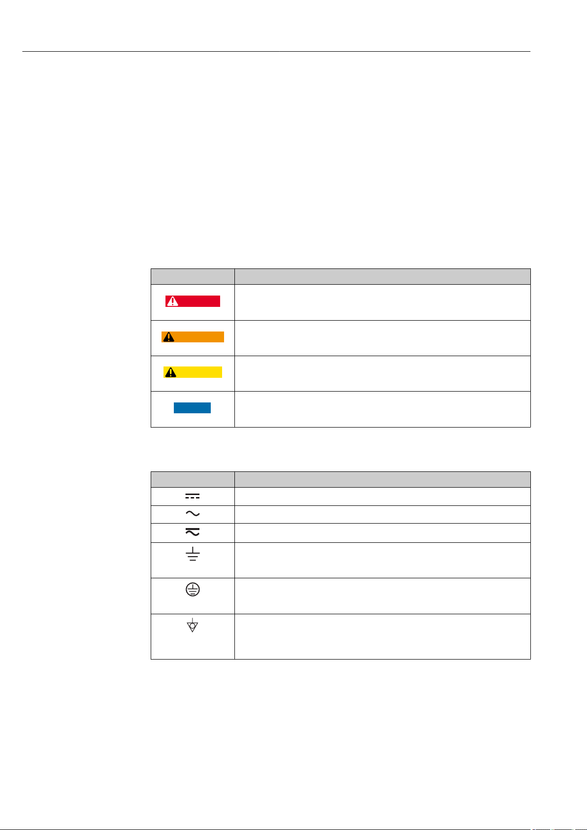
1.2.1 Safety symbols
Symbol Meaning
DANGER!
This symbol alerts you to a dangerous situation. Failure to avoid this situation will
result in serious or fatal injury, as well as a risk of fire or explosion.
WARNING!
This symbol alerts you to a dangerous situation. Failure to avoid this situation will
result in a risk of serious or fatal injury, fire or explosion.
Note
This symbol alerts you to a dangerous situation. Failure to avoid this situation will
result in a risk of minor or moderate injury and damages to properties.
NOTE!
This symbol contains information on procedures and other facts that do not result in
personal injury.
1.2.2 Electrical symbols
Symbol Meaning
Direct current
Alternating current
Direct current and alternating current
Ground connection
A grounded terminal that, as far as the operator is concerned, is grounded via a
grounding system.
Protective ground connection
A terminal that must be connected to the ground prior to establishing any other
connections.
Equipotential connection
This connects with the grounding system at the plant. It includes equipotential line
and single point ground systems, depending on the norms of each country or
company.
4 Endress+Hauser
Page 5
Prothermo NMT539 About this document
A
1.
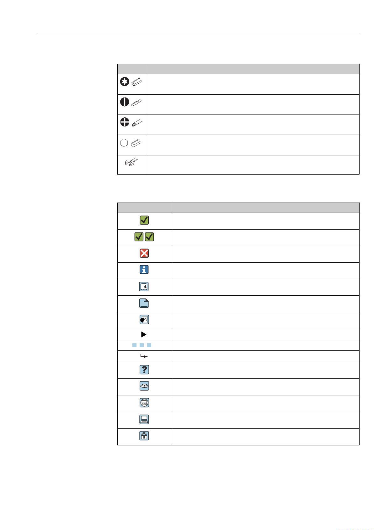
1.2.3 Tool symbols
Symbol Meaning
Torx screwdriver
A0013442
Flat blade screwdriver
A0011220
Phillips screwdriver
A0011219
Allen key
A0011221
Open-ended wrench
A0011222
1.2.4 Symbols for certain types of information
Symbol Meaning
Permitted
Procedures, processes or actions that are permitted
Preferred
Procedures, processes or actions that are preferred
Forbidden
Procedures, processes or actions that are forbidden
Tip
Indicates additional information
Reference to documentation
Reference to page
Reference to graphic
Notice or individual step to be observed
, 2., 3. … Series of steps
Result of an operation or commissioning
Help in the event of a problem
Visual inspection
Operation via the local display
Operation via operating tool
Write-protected parameter
Endress+Hauser 5
Page 6
About this document Prothermo NMT539
1.
-
.
1.2.5 Symbols in graphics
Symbol Meaning
1, 2, 3 ... Item numbers
, 2., 3. … Series of steps
A, B, C, ... Graphics
A-A, B-B, C-C, ... Cross-sections
Hazardous area
Indicates the hazardous area
Safe area (non-hazardous area)
Indicates the non-hazardous area
1.2.6 Device symbol
Symbol Meaning
Safety instructions
Observe the safety instructions contained in the associated Operating Instructions.
Temperature resistance of the connection cables
Specifies the minimum value of the temperature resistance of the connection cables.
6 Endress+Hauser
Page 7
Prothermo NMT539 About this document
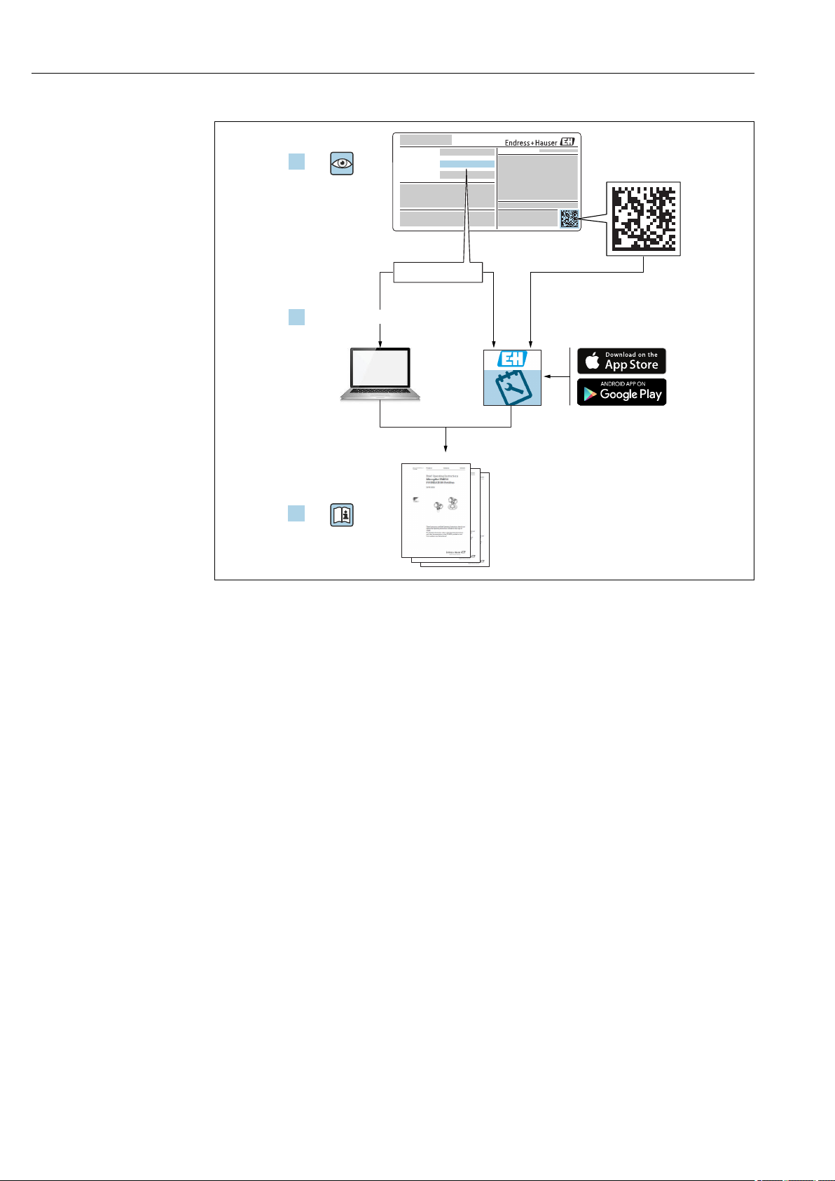
1.3 Documentation
For an overview of the scope of the relevant Technical Documentation included with
the product, refer to the following:
• The W@M Device Viewer: Enter the serial number from the nameplate
(www.endress.com/deviceviewer).
• The Endress+Hauser Operations App: Enter the serial number from the nameplate
or scan the 2-D matrix code (QR code) on the nameplate.
1.3.1 Technical information
The Technical Information contains all the technical data on the device and provides an
overview of the accessories and other products that can be ordered for the device.
Device Technical Information
Prothermo NMT539 TI01005G
1.3.2 Operating instructions (BA)
The Operating Instructions contain all the information that is required during various
phases of the life cycle of the device: from product identification, incoming acceptance and
storage, to mounting, connection, operation and commissioning through to
troubleshooting, maintenance and disposal.
The Operating Instructions also contain detailed descriptions of each parameter in the
operation menu. The description is aimed at those who work with the device over the
entire life cycle and perform specific configurations.
Device Operating Instructions
Prothermo NMT539 BA01025G
BA01026G
1.3.3 Safety instructions (XA)
Feature 010 ("Approval") Meaning Ex / XA
A Ex ia IIB T4 Ex463-820XJ
Ex1060-953XJ
Ex496-826XJ
B ATEX Ex ia IIB T2-T6 XA00585G
C Ex ia IIB T2 Ex495-823XJ
E Ex d[ia] IIB T4 Ex1061-986XJ
F IEC Ex ia IIB T2-T6 XA01790G
G NEPSI Ex ia IIB T2-T6 XA01259G
7 FM C/US IS Ci. I Div.1 Gr. C-D Ex461-851-1
Ex461-850-1
1.4 Registered trademarks
FieldCare
Registered trademark of the Endress+Hauser Process Solutions AG, Reinach, Switzerland.
HART
Registered trademark of the FieldComm Group, Austin, USA.
®
®
Endress+Hauser 7
Page 8

Basic safety instructions Prothermo NMT539
2 Basic safety instructions
2.1 Requirements for personnel
The personnel for installation, commissioning, diagnostics and maintenance must fulfill
the following requirements:
Be specialists who are trained and have a relevant qualification for this specific
‣
function and task.
Be authorized by the plant owner-operator.
‣
Be familiar with local/national regulations.
‣
Before starting work, read and understand the instructions in the Operating
‣
Instructions and supplementary documentation as well as the certificates (depending
on the application).
Follow instructions and comply with basic conditions.
‣
The operating personnel must fulfill the following requirements:
Be instructed and authorized according to the requirements of the task by the facility's
‣
owner-operator.
Follow the instructions in this manual.
‣
2.2 Designated use
Application and measured materials
Depending on the version ordered, the device can also be used with potentially explosive,
flammable, poisonous or oxidizing materials.
Devices that are used in hazardous areas have corresponding labels on their nameplates.
To ensure that the device remains in proper condition for the operation time:
Only use the device in full compliance with the data on the nameplate and the general
‣
conditions listed in the Operating Instructions and supplementary documentation.
Check the nameplate to verify if the device can be put to its intended use in hazardous
‣
areas.
If the device is not operated at an atmospheric temperature, compliance with the
‣
relevant basic conditions specified in the relevant device documentation is absolutely
essential.
Protect the device permanently against corrosion from environmental influences.
‣
Observe the limit values in the "Technical Information".
‣
The manufacturer is not liable for damage caused by improper or non-designated use.
2.3 Workplace safety
For work on and with the device:
Wear the required personal protective equipment according to local/national
‣
regulations.
8 Endress+Hauser
Page 9

Prothermo NMT539 Basic safety instructions
2.4 Operational safety
Risk of injury!
Operate the device in proper technical conditions and fail-safe conditions only.
‣
The plant owner-operator is responsible for interference-free operation of the device.
‣
Modifications to the device
Unauthorized modifications to the device are not permitted and can lead to unforeseeable
dangers:
If modifications are nevertheless required, contact your Endress+Hauser Sales Center.
‣
Repair
To ensure continued operational safety and reliability:
Carry out repairs on the device only if they are expressly permitted.
‣
Observe local/national regulations pertaining to repair of an electrical device.
‣
Use only original spare parts and accessories from Endress+Hauser.
‣
Ex-area
Observe the following notes to eliminate the risk of danger to persons or the facility when
the device is used in Ex-areas (e.g. explosion protection, pressure equipment safety):
Check the model nameplate to ensure that the ordered device is explosion proof.
‣
Observe the specifications in the separate supplementary documentation attached to
‣
these Instructions.
2.5 Product safety
This device was designed in accordance with GEP (Good Engineering Practice) to meet
state-of-the-art safety requirements, has been tested and left the factory in a condition in
which it is safe to operate. It meets the general safety standards and legal requirements.
Endress+Hauser 9
Page 10

Product description Prothermo NMT539
3 Product description
3.1 Product design
NMT539 performs precise liquid and gas phase average temperature measurement, which
makes it ideal for inventory management of large-scale tanks.
It is equipped with a capacitance WB device in crude oil and two-phase liquids, and it
performs accurate average temperature and WB measurements.
The position of the flange cannot be adjusted in a welding flange type.
3.2 Technical data
Item Details
Application • Flange installation: Standard 50.8 mm (2 in)
• Temperature measuring range: Maximum length 99.999 m (3.94 in) (ATEX, IECEx, NEPSI, FM C/US), maximum length
40.000 m (1.57 in) (TIIS)
• WB measuring range: 1 m (3.28 ft) or 2 m (6.56 ft)
Measuring principle • Temperature measurement
NMT539 consists of up to 16 platinum resistance elements (Pt100) in a SUS316 protection tube. Pt100 has a unique
characteristic of linear resistance change with respect to the surrounding ambient temperature change. A module in the
NMT539 converter receives this resistance signal change as an input variable and converts it to temperature data. The
converted and calculated data are then transmitted to the host device as a local HART signal.
• Water bottom (water interface level) measurement
An attached capacitance level measurement probe detects the presence of water.The WB is converted into a given frequency
variable (default setting) and its data is transmitted via local HART converter to the connected host device.
Minimum element
interval (distance)
Device structure RTD average temperature signal for local HART conversion
Measuring range • Temperature measurement
• Standard specifications: 150 mm (5.9 in) (Order Code: 030 Option 1, 4, 5)
• High temperature / Low temperature: 400 mm (15.75 in) (Order Code: 030 Option 2, 3, 6)
If NMT539 comes with a WB (water bottom) probe option, the maximum number of WB internal elements is two,
because of the restriction posed by the internal diameter.
RTD average temperature measurement + local HART converter
Average temperature + WB measurement + local HART converter
• Temperature conversion: –200 to 235 °C (–328 to 455 °F) (–170 to 235 °C (–274 to 455 °F) TIIS)
• Standard: –40 to 100 °C (–40 to 212 °F) (–20 to 100 °C (–4 to 212 °F) TIIS)
• Wide range: –55 to 235 °C (–67 to 435 °F) (–20 to 235 °C (–4 to 455 °F) TIIS)
• Cryogenic: –170 to 60 °C (–274 to 140 °F)
• Probe length: Maximum length 99.999 m (328.08 ft) (ATEX, IECEx, NEPSI, INMETRO, FM C/US)
Maximum length 40.000 m (131.23 ft) (TIIS)
• WB measurement
Standard probe range: 1 m (3.28 ft) or 2 m (6.56 ft)
–200 to 100 °C (–328 to 212 °F), which is below cryogenic temperature, can be accommodated upon request.
Output signal Local HART protocol, exclusively for the local host device
Alarm signal Error information can be accessed via the following interfaces and transmitted digital protocol (refer to "Prothermo NMT539
Operating Instructions and Description of Instrument Function" for the following instruments):
• NRF590 (BA00256F, BA00257F)
• NMS5 (BA00401G)
• NMS8x (BA1456G, BA1459G, BA1462G)
• NMR8x (BA01450G, BA01453G)
• NRF81 (BA01465G)
Local HART load Minimum loading for local HART circuit: 250 Ω
Cable glands Thread G1/2, Thread NPT1/2, Thread M20
Supply voltage • DC 16 to 30 V: Ex ia
• DC 20 to 24 V: Ex d [ia]
10 Endress+Hauser
Page 11
Prothermo NMT539 Product description
Item Details
Power consumption Ex ia: 6 mA (temperature measurement), 12 mA (WB measurement), Ex d [ia]: 8 mA (temperature measurement), 14 mA
(WB measurement)
Reference operating
conditions
Measured value
resolution
Maximum
measurement error
Ambient
temperature
Storage temperature –40 to 85 (–40 to 185)
Climate class DIN EN 60068-2-38 (test Z/AD)
Protection class • IP66/68 NEMA4X/6P: Converter set equipped with a temperature device or a WB device
Electromagnetic
compatibility
Process temperature
range
Process pressure Atmospheric pressure (absolute pressure 1 bar, 100 kPa, 14.5 psi)
Data transmission • Minimum cable diameter: #24 AWG
• Temperature: 25 °C (77 °F) ± 5 °C (9 °F)
• Pressure: 1 013 mbar abs. ± 20 mbar abs. (1 013 hPa abs. ± 20 hPa abs. , 14.7 psi abs. ± 0.3 psi abs.)
• Relative humidity (air): 65 % ± 20 % (linearity)
• Converter and precision resistor combination or converter and probe combination
• WB measurement range: 80 % (100 to 900 mm (3.94 to 35.43 in))
• The factory default is adjusted based on DC (er) = 2.1. Adjustment should be made on-site when necessary
• Temperature: ≤ 0.1 °C (0.18 °F)
• WB: ≤ 0.1 mm (0.004 in)
The values below represent performances under the reference conditions (including linearity, repeatability, hysteresis).
Conversion accuracy
Temperature Standard /PTB spec. ± 0.1 °C (0.18 °F)
WB 1 m (3.28 ft) spec. ± 2 mm (0.08 in)
2 m (6.56 ft) spec. ± 4 mm (0.16 in)
Probe system
Temperature Standard spec. ± 0.15 °C + 0.002 °C x |t| (0.27 °F + 0.0036 °F |t|)
IEC 60751 / DIN EN 60751 / JIS C1604 Class A temperature element
PTB spec. ± (0.3 °C + 0.005 °C x |t|) / 10 ((0.54 °F + 0.009 °F x |t|) / 10)
Class 1/10B temperature element
WB 1 m (3.28 ft) spec. ± 2 mm (0.08 in)
2 m (6.56 ft) spec. ± 5 mm (0.2 in)
Overall accuracy
Temperature Standard spec. Conversion accuracy ± 0.1 °C (0.18 °F) + Environmental effect ± 0.05 °C (0.09 °F) +
Class A temperature element ± 0.15 °C + 0.002 °C x |t| (0.27 °F + 0.0036 °F x |t|)
PTB spec. Conversion accuracy ± 0.1 °C (0.18 °F) + Environmental effect ± 0.05 °C (0.09 °F) +
Class 1/10B temperature element ± (0.3 °C + 0.005 °C x |t|) / 10 (0.54 °F +
0.009 °F x |t| / 10)
WB 1 m (3.28 ft) spec. Conversion accuracy ± 2 mm (0.08 in) + Probe accuracy ± 2 mm (0.08 in)
2 m (6.56 ft) spec. Conversion accuracy ± 5 mm (0.2 in) + Probe accuracy ± 5 mm (0.2 in)
• Accuracy can be improved for each application by making adjustments on-site, such as adjusting the offset.
• |t| represents the temperature of the measured item.
• –40 to 85 (–40 to 185)
• –20 to 60 °C (–4 to 140 °F): TIIS
• IP65 NEMA4X: Converter only (open housing: IP20)
When installing the probes to metal or concrete tanks and when using a coax probe:
• Interference emission according to EN 61326, Electrical Equipment Class B
• Interference immunity according to EN 61326, Annex A (Industrial)
Temperature probe: –175 to 235 °C (–274 to 455 °F)
WB probe: –0 to 100 °C (32 to 212 °F)
• Pressure tank: If the pressure inside the tank exceeds the process pressure shown above, install a stilling well
(protective tube) without holes or slits in the NMT539 to protect the probe from the pressure.
• Static pressure: Because NMT539 has undergone an airtightness test at an absolute pressure of 7 bar, it can withstand
static pressure head in the 50 m (164 ft) range in petroleum/chemical product applications.
• Cable type: Twist pair with a shield
Endress+Hauser 11
Page 12

Product description Prothermo NMT539
Item Details
Weight Approx. 13 kg
Conditions
• Number of elements: 16 points
• Temperature probe: 10 m (32.8 ft)
• WB probe: 1 m (3.28 ft)
• Flange: 2" 150 lbs RF, SUS316
Material • Temperature measurement elements: Class A Pt100, IEC60751/DIN EN60751/JISC1604
• Housing: Aluminum die cast
• Temperature probe: SUS316, SUS316L (refer to the "Dimension")
• WB probe: SUS316 (center rod SUS 304 / PFA protected)
Flange specifications • 10K 50A RF, SUS316, flange JIS B2220
• NPS 2" Cl.150 RF, SUS316 flange ASME B16.5
• DN50 PN10 B1, SUS316, flange EN1092-1 (DIN2527 B)
• 50A 150 lbs RF, SUS316, flange JPI 7S-15
• Universal coupling, G3/4, (converter only)
• M20 threaded (converter only)
CE approval By attaching the CE mark, Endress+Hauser confirms that the instruments have passed the required tests.
External standards
and guidelines
Ex approvals ATEX
• EN 60529
• Protection class of housing (IP-code)
• EN 61326
• Emissions (equipment class B), compatibility (appendix A – industrial area)
• II 1/2 G Ex ia IIB T2-T6 Ga/Gb (converter with temperature device and/or WB device)
• II 2G Ex ia IIB T2-T6 Gb (converter only)
IEC
• Ex ia IIB T2-T6 Ga/Gb (converter with temperature device and/or WB device)
• Ex ia IIB T2-T6 Ga (converter only)
FM C/US
Converter with temperature device and/or WB device
• IS Cl. I, Div. 1, Gr. C, D T2-T6
• IS Cl. I, Zone 0, AEx ia IIB Ga T2-T6
• NI Cl. I, Div. 2, Gr. C, D T2-T6
Converter only
• IS Cl. I, Div. 1, Gr. C, D T4
• IS Cl. I, Zone 0, AEx ia IIB Ga T4
• NI Cl. I, Div. 2, Gr. C, D T4
TIIS
• Ex ia IIB T4 (converter with temperature device and/or WB device) (converter only)
• Ex ia IIB T2 (converter with temperature device)
• Ex d[ia] IIB T4 (converter with temperature device and/or WB device)
NEPSI
• Ex ia IIB T2-T6 (converter with temperature device and/or WB device)
• Ex ia IIB T2-T6 Ga (converter only)
12 Endress+Hauser
Page 13
Prothermo NMT539 Product description
b c
a
e
d
f
3
2
1
3.3 Description of functions
Detailed descriptions of the function groups, functions and parameters are given in
"NMT539 Operating Instructions and Description of Instrument Functions. "When
NMT539 with WB probe and NRF590 are used together, confirm that the supply voltage
to TMD1/NMS/TGM/NRF590 is stable at a voltage of 100 VAC or higher.
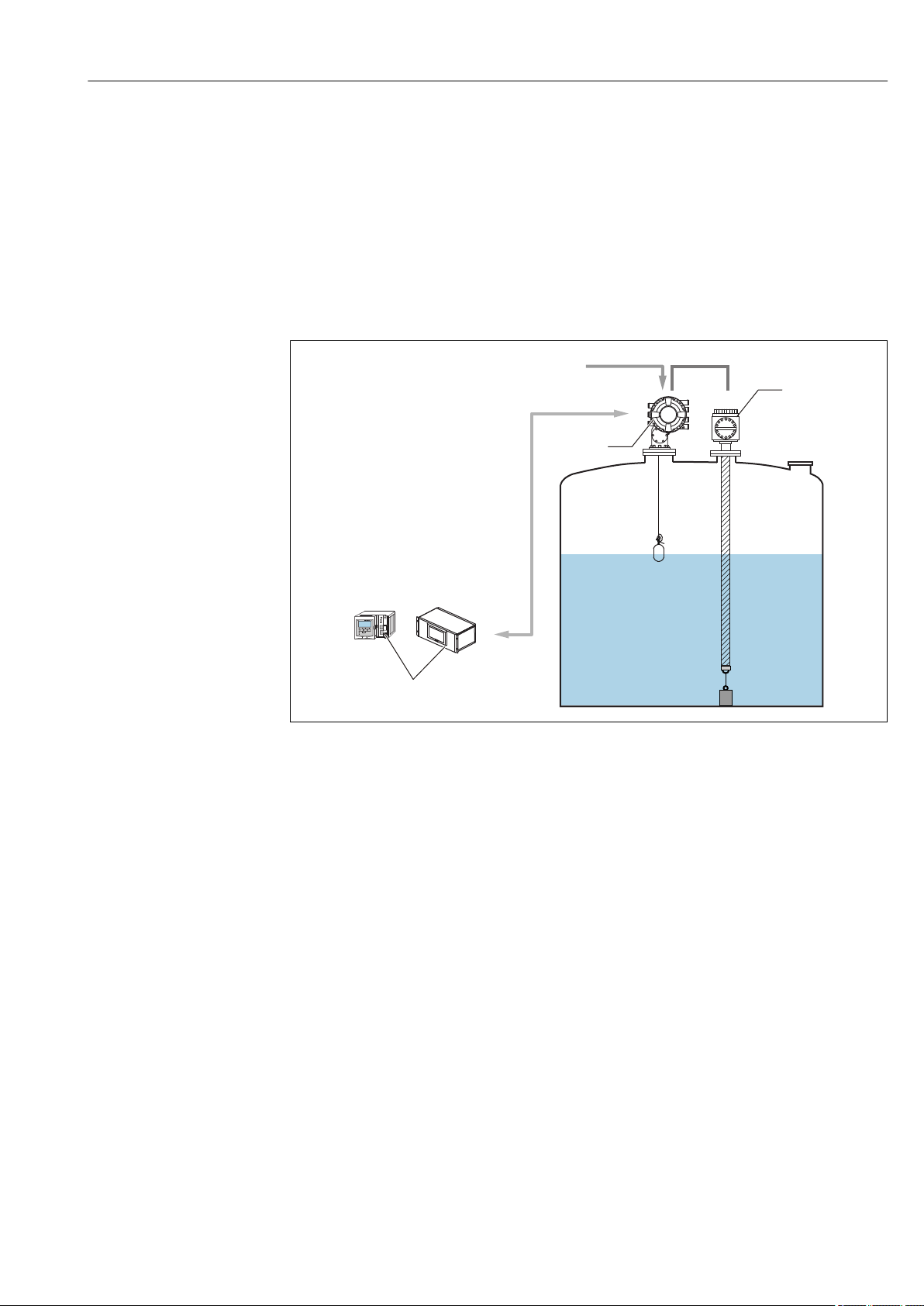
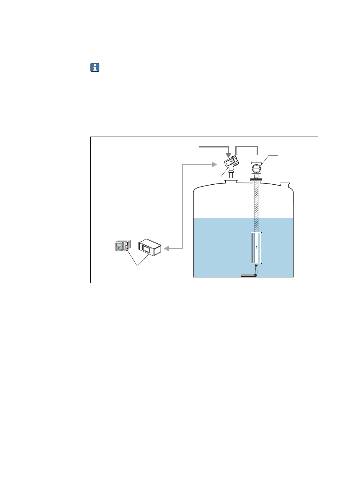
3.3.1 NMT539 Ex ia and NMS8x Exd [ia] combination
he connection of NMT539 shown below is only available for connection with NMS5 or
NMS8x.
A0038539
1 NMS8x and NMS539 system design
a Fieldbus protocol
b Power supply
c Local HART (Ex i) loop (data transmission)
d Level
e Gas temperature
f Liquid temperature
1 Tankvision
2 NMS8x
3 NMT539
Typical application of NMT539 converter + temperature probe version
NMT539 is the successor of the former NMT535. For proper migration, NMT539 has
inherited all the functionality and specifications of NMT535, including connection flange
specifications, cable entries and wiring method. Since NMS5 or NMS8x is provided with
WB measurement function, they can be combined with the converter + average
temperature probe version of NMT539. When the converter + average temperature probe
+ WB probe version is combined with NMS5 or NMS8, the product in the tank will
simultaneously be managed with level, continuous temperature and WB measurements.
Most changes and parameter settings for NMT539 can be performed by NMS5 or NMS8x.
NMT539 receives liquid level data from NMS5 or NMS8x and then calculates the average
temperature of the liquid and gas phases. The calculated average temperature data of the
Endress+Hauser 13
Page 14
Product description Prothermo NMT539
b
a
c
e
d
f
3
2
1
liquid and gas phases are transmitted to NMS8x or NMS5 along with the measured
temperature of each element and the NMT539 device status.
All gathered data in the field interface unit are sent to inventory management
software (Tankvision) or to NMS8x, NMS5x, NMS7, NMR8x, NRF8x or NRF590.
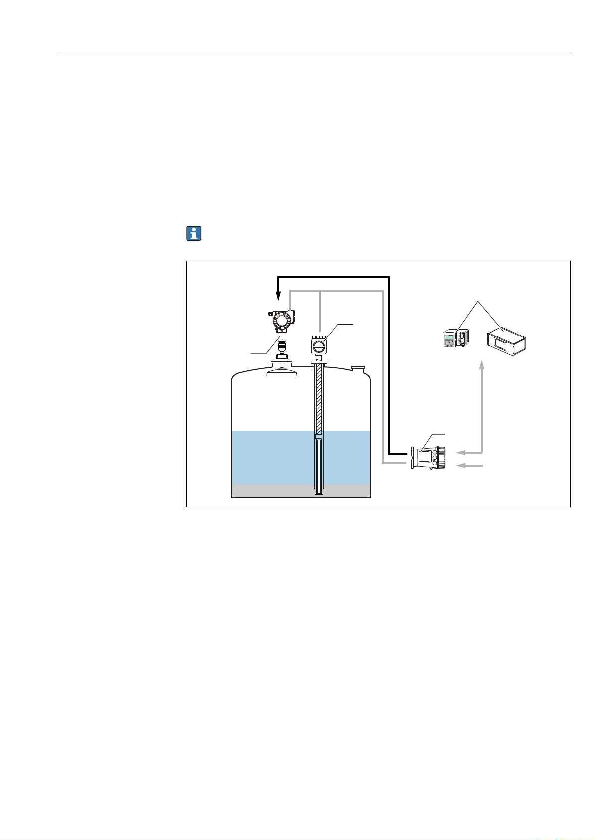
3.3.2 NMT539 Ex ia and NMR8x Ex d [ia] combination
The connection of NMT539 shown below is only available for connection with NMR8x Ex
d [ia].
NRF81 is required as a gateway for FMR5xx and NMT539 Tankvision when using FMR5xx
Ex ia radar.
2 NMT539 Ex ia and NMR8x combination
a Fieldbus protocol
b Power supply
c Local HART (Ex i) loop (data transmission)
d Level
e Gas temperature
f Liquid temperature
1 Tankvision
2 NMR8x
3 NMT539
A0038540
14 Endress+Hauser
Page 15
Prothermo NMT539 Product description
2
3
1
a
b
c
d
f
e
4
g
h
3.3.3 NMT539 Ex ia and NRF590 Ex d [ia] combination
Typical application of NMT539 converter + temperature probe + WB probe version
The NMT539 converter + temperature probe + WB probe version is utilized most
effectively in combination with radar level gauging. Water interface, temperature and
liquid level measurement, with data collection and calculations via the NRF590 or NRF81,
allow for optimal inventory control.Details on NMT539 functions and data can be accessed
from NRF81 or NRF590. NMT539 receives radar level data from NRF590 or NRF81 and
then calculates the average temperature of the liquid and gas phases. The calculated
average temperature data of the liquid and gas phases are transmitted to NRF81 or
NRF590 along with the measured temperature of each element and the NMT539 device
status.
All gathered data in the field interface unit are sent to inventory management
software (Tankvision) or to NMS8x, NMS5x, NMS7, NMR8x, NRF8x or NRF590.
A0038541
3 NMT539 Ex ia and NRF590 Ex d [ia] combination
a FMR power supply (DC/Ex i)
b Local HART (Ex i) loop (data transmission)
c Gas temperature
d Level
e Liquid level temperature
f Water
g Fieldbus protocol
h Power supply
1 FMR540
2 NMT539
3 NRF81/NRF590
4 Tankvision
Endress+Hauser 15
Page 16
Product description Prothermo NMT539
a
b
c
d
1
3
4
2
5
b
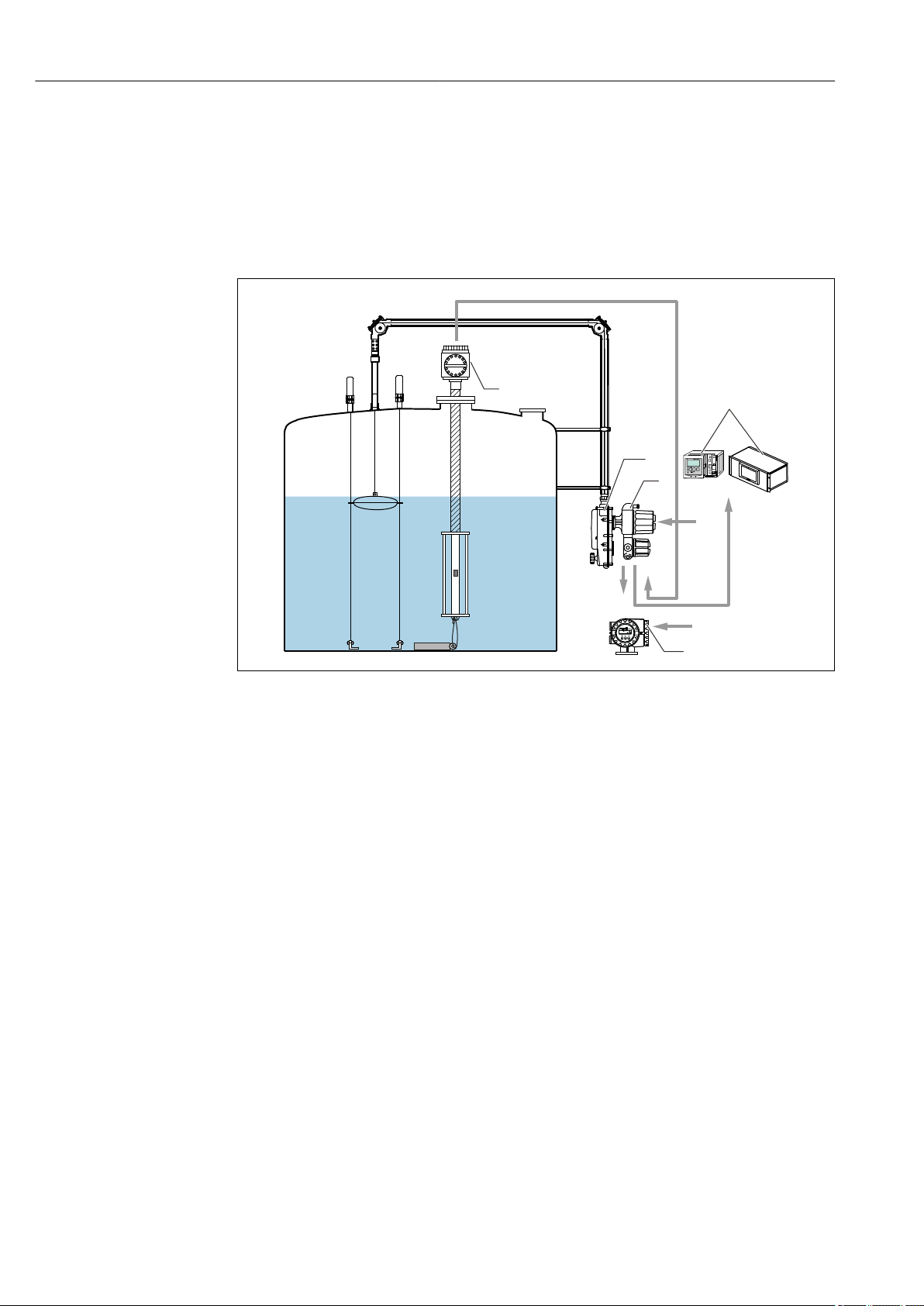
3.3.4 NMT539 Ex d [ia] and TMD1 Ex d combination
Average temperature device NMT539 can be connected to Transmitter TMD1 or Servo
Level Gauge TGM5 via local HART (Ex d) communication. Because local HART
communication is digital, it is able to send a larger volume of information compared to the
conventional RTD method. This means that NMT539 can work with not just DRM9700 but
also with NRF560. If NMT539 WB probe and NRF560 are used together, confirm that the
supply voltage to TMD1 is stable at 100 VAC or higher.
4 NMT539 Ex d [ia] and TMD1 combination
a Local HART (Ex d) loop (data transmission)
b Power supply
c Fieldbus protocol
d HART (Ex d) loop (data transmission)
1 NMT539
2 Tankvision
3 LT5
4 TMD1
5 NRF560
A0038542
16 Endress+Hauser
Page 17
Prothermo NMT539 Product description
2
3
b
a
c
d
b
4
5
6
7
1
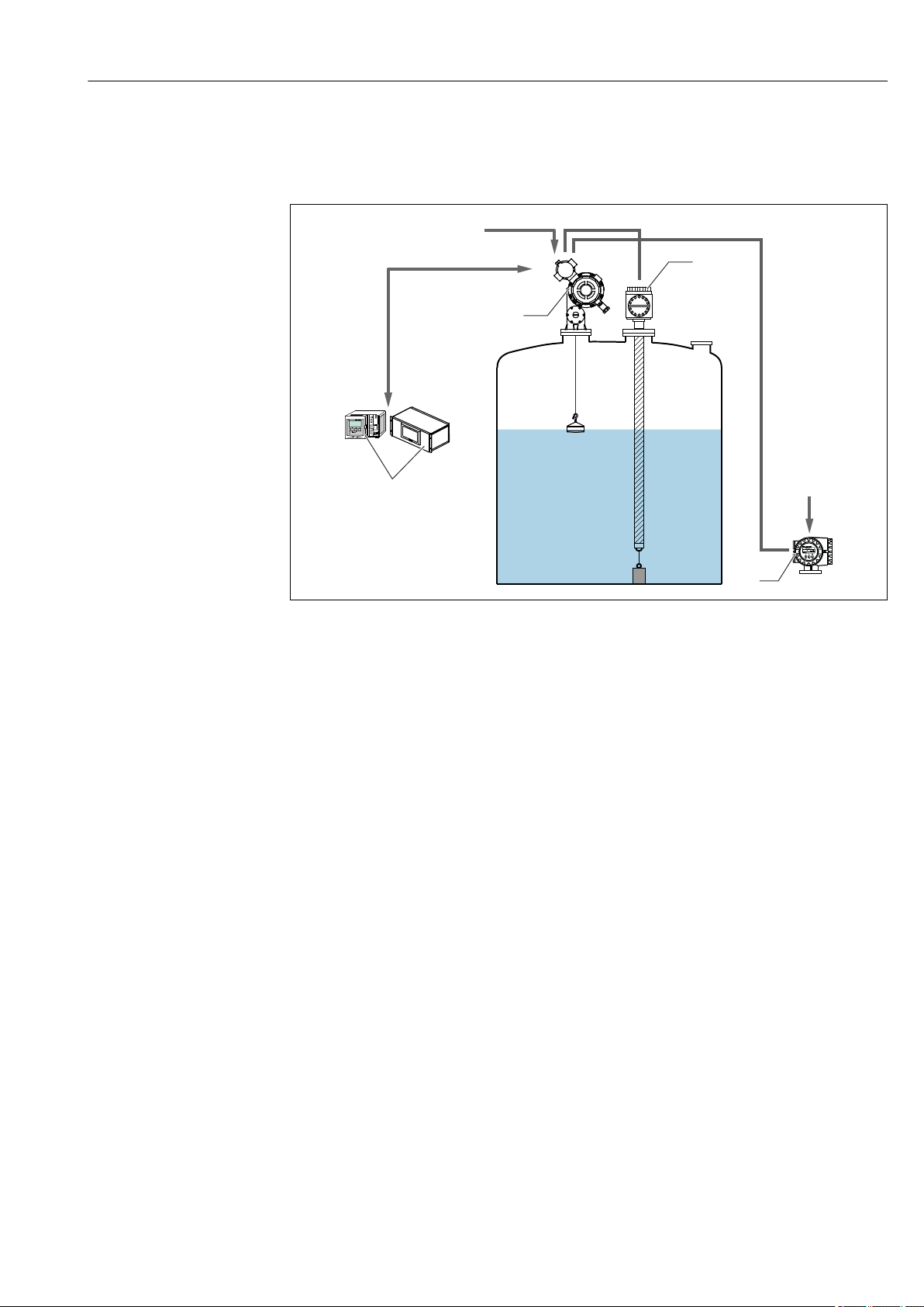
3.3.5 NMT539 Ex d [ia] and TGM5 combination
When NMT539 with WB probe and NRF560 are used together, confirm that the supply
voltage to TGM5 is stable at 100 VAC or higher.
A0038543
5 NMT539 Ex d [ia] and TGM5 combination
a Fieldbus protocol
b Power supply
c Local HART (Ex d) loop (NMT539 and TGM5)
d Local HART (Ex d) loop (TGM5 and NRF560)
1 Tankvision
2 TGM5
3 NMT539
4 NRF560
5 Level
6 Gas temperature
7 Liquid temperature
Endress+Hauser 17
Page 18

Adjustment and settings Prothermo NMT539
4 Adjustment and settings
4.1 Local HART connection
4.1.1 Endress+Hauser tank gauging instrument
NMT539 is designated to work with Endress+Hauser tank instruments tank side monitors
NRF590, NRF81 or Proservo NMS5, NMS7, NMS8x or NMR8x to build a comprehensive
instrumentation system. Both temperature and/or WB information is transmitted via
HART loop. NRF590, NRF81 and NMS5, NMS, NMS8x and NMR8x have a settings menu
for the NMT Series by default, which means that they can configure NMT539 default
settings.
• The parameters listed in this document are parameters that can be checked when
the instruments are connected to NMT539 with FieldCare. Since the parameters
that can be checked from the HMI of the connected HART Master, such as NMS8x
and NMS5, differ depending on which HART Master is being used, refer to the
respective operating instructions.
• Before starting up NMT539, refer to "Prothermo NMT539 Operating Instructions"
and check the installation procedure.
• There are four types of standard basic data depending on the NMT539
measurement function.
4.1.2 Measuring functions
Temperature measurement
0 Converter only
1 Temperature + converter
These four types of basic data are available as standard.
• Average liquid temperature
• Average gas temperature
• Level (VH02 measured distance)
• Device status
Water bottom measurement
2 WB probe + converter
These four types of basic data are available as standard.
• WB level
• WB probe capacitance
• WB probe frequency
• Device status
Temperature + WB + converter
3 Temperature + WB + converter
These four types of basic data are available as standard.
18 Endress+Hauser
Page 19

Prothermo NMT539 Adjustment and settings
• Average liquid temperature
• WB level
• Average gas temperature
• Device status
4.2 Device configuration: NRF590
Connect the loop-powered local HART communication cable from NRF590 (intrinsically
safe side compartment) to NMT539 according to "Prothermo NMT539 Operating
Instructions. " NRF590 has been designed to recognize NMT539 as a specific Endress
+Hauser local HART device.
4.2.1 HART scanner
Once NMT539 and NRF590 have been wired together, all HART devices will be scanned
automatically when NRF590 is turned on.
Not all NRF590 are fully compatible for recognizing NMT539. Contact your Endress
+Hauser Sales Center for information on NRF590 software and hardware version
compatibility.
4.2.2 NMT539 specific parameter setup for NRF590
The configuration of NMT539 parameters displayed on NRF590 depends on the installed
software and hardware versions of NRF590. Refer to the NRF590 operating manual to
determine accessible parameters. All default settings and parameter configurations can be
carried out using FieldCare. Detailed information will be provided in the following sections.
4.3 Device configuration: NMS5/NMS7
NMS5/NMS7 are specifically designed to recognize NMT539 as HART Master. Terminals
24 and 25 of NMT539 and NMS5/NMS7 are connected with a local HART cable.
Connection between NMS5/NMS7 and NMT539 is required for Ex Approval. Follow
the separate BA01025G operating instructions, "4.4.Terminal connection."
4.3.1 Preparation for NMS5/NMS7 configuration
NMS5/NMS7 must be set to default before connecting to NMT539.
Code Display Details
GVH362 NMT Connection Select "NMT Connection" and "Average" and configure the NMT.
To change this parameter, an access code is required. For
details, see "Prothermo NMT539 Operating Instructions."
4.3.2 Configuring NMT539 with NMS5/NMS7
NMT539 parameters can be configured using the NMS5/NMS7 programming matrix G4
"Temperature Device."
Typical NMT539 parameters (same as NMT535) are displayed in the NMS5/NMS7
matrix.
WB probe information is not available on NMS5/NMS7 ROM version 4.24 or earlier
versions. Contact your Endress+Hauser Sales Center to update existing NMS5/NMS7
functions.
Endress+Hauser 19
Page 20

Adjustment and settings Prothermo NMT539
G0 Static Matrix
Code Display Details
GVH010 Liquid temp NMT539 displays the average liquid temperature.
GVH013 Gas temp NMT539 displays the average gas temperature.
G4 Temperature Matrix
Code Display Details
GVH440 Liquid temp Displays the same value indicated in GVH010: Liquid temp
GVH441 Gas temp Displays the same value indicated in GVH013: Gas temp
GVH442 Level The liquid level collected from NMS5/NMS7 is selected as either
GVH000: Level (Displacer position) or GVH008: Level data
(Level). NMT539 calculates both liquid and gas phase
temperatures based on this liquid level data.
GVH447 Element No. 0 temp Checks that the measuring temperature resistor temperature
conversion is executed correctly.
The tolerance range is –1.0 to 1.0 °C (–30.2 to 33.8 °F).
GVH449 Element temp 17 temp This temperature is used for checking when shipping from the
factory.
GVH450-459 Element temp No.1-10
temp
GVH460-469 Element No.1-10
position
GVH470 Select point A matrix is selected for GVH471 "Zero Adjust," GVH473 "Element
GVH480 Diagnostic Displays error code messages. Refer to the error code chart in
GVH482 Element number The number of elements installed on the temperature
GVH485 Type of interval Sets measurement element intervals. If the element intervals are
GVH486 Bottom point Sets the height of the lowest element. This is only set when the
GVH487 Element interval The element interval is entered if "Equal interval" was selected in
The measured temperature is the temperature data collected
from each element (maximum 16 points). The temperature
measurement elements 11 to 16 are selected from GVH470
"Select point," and the selected element is displayed in GVH473
"Element temp."
Indicates the position of each element in the probe. Temperature
measurement elements 11 to 16 are selected from GVH470
"Select point," and the selected element is displayed in GVH474
"Element position."
temp" and GVH474 "Element position," and required element
data are input.
this manual.
measurement tube is entered.
equal, select GVH487 "Element interval" to set the interval, and
then select GVH486 "Bottom point" to set the height of the
lowest edge of the elements. If the element intervals are not
equal, manually set the intervals.
This parameter configuration is only used to change the
theoretical element position within NMT539's software for
average temperature calculation. The physical positions of
the elements will not change.
elements have equal intervals.
This parameter configuration is only used to change the
theoretical element position within NMT539's software for
average temperature calculation. The physical positions of
the elements will not change.
GVH485 "Type of interval."
This parameter configuration is only used to change the
theoretical element position within NMT539's software for
average temperature calculation. The physical positions of
the elements will not change.
20 Endress+Hauser
Page 21

Prothermo NMT539 Adjustment and settings
a
4.4 Configuring NMT539 with NMS8x/NMR8x/NRF81
NMS8x, NMR8x and NRF81 are specifically designed to recognize NMT539 as HART
Master. Terminals E1 and E2 or B3 and C3 of NMR8x, NRF81 and NMS8x are connected
to NMT539 with a local HART cable.
Connection from NMS8x, NMR8x and NRF81 to NMT539 is required for Ex Approval.
Follow the connection instructions in the separate BA01025G operating instructions,
"Terminal connection."
4.4.1 Preparation for configuring NMS8x/NMR8x/NRF81
NMS8x, NMR8x and NRF81 must be set to default before connecting to NMT539.
Setting procedure
1. From the Expert menu, choose Input/Output → HART device → HART device(s) →
NMT device configuration.
2. Select "Yes" for Config. device?
3. Enter the bottom temperature element in Bottom point (see diagram below).
This completes the setting procedure.
A0038544
6 Position of the bottom-point temperature element
a Distance between the bottom-point temperature element to the reference (tank bottom or reference plate)
Default a is 500 mm (19.69 in), but this can be modified as needed.
Liquid temperature display
Item Details
Navigation Operation → Temperature → Liquid temp
Description Displays the average or spot temperature of the measured liquid.
Additional information Read access: Operator
Write access: -
Endress+Hauser 21
Page 22

Adjustment and settings Prothermo NMT539
Manual gas phase temperature display
Item Details
Navigation Operation → Temperature → Manual gas phase temperature
Description Displays the temperature of the measured gas.
Additional information Read access: Operator
Write access: -
Display of element temperature 1-24
Item Details
Navigation Operation → Temperature → Manual gas phase temperature
Description Displays the NMT element temperature.
Additional information Read access: Operator
Write access: -
Selection of liquid level
Item Details
Navigation Setting → Advanced settings → Application → Tank settings → Level → Select
liquid level
Description Sets the liquid level source.
Selection No input
HART device, Level 1-15
Level SR (see Note)
Liquid level (see Note)
Displacer position (see Note)
AIO B1-3 value
AIO C1-3 value
AIP B4-8 value
AIP C4-8 value
Factory setting The setting is different depending on the device.
Additional information Read access: Operator
Write access: -
The display will be different depending on the selected options and equipment
settings.
22 Endress+Hauser
Page 23

Prothermo NMT539 Adjustment and settings
HART dev. confg
Config. device?
Access code
Total no element
Bottom point
Temp elem. short
Temp elem. open
Output at error
Gain adjust
Kind of interval
Element interval
Element setup
Select element
Zero adjust
Element temp
Element position
4.4.2 NMS8x/NMR8x/NRF81 configuration
Below are NMT539-related parameters. For details on the operation of NMS8x, NMR8x
and NRF81, see their respective operating instructions.
The following parameters can be checked from the display accessed through the
Main Menu → Expert → Input/Output → HART device → HART device(s) [MenuName].
A0038545-EN
7 Parameter structure
Configure device?
Item Details
Navigation Expert → Input/Output → HART Device → HART device(s) [MenuName] →
HART device configuration → Config. device? (14728)
Description Configures the NMT device.
Selection Yes (The device is recognized as NMT)
No (The device will not be recognized)
Factory setting No
Additional information Read access: Operator
Write access: Maintenance
Endress+Hauser 23
Page 24

Adjustment and settings Prothermo NMT539
Access code
Item Details
Navigation Expert → Input/Output → HART device → HART device(s) [MenuName] →
HART Device configuration → Access code (14714)
Conditions Configure device? = Yes
Description Displays the access code.
Input range 0-65535
Factory setting 0
Additional information Read access: Operator
Write access: Maintenance
Total number of elements
Item Details
Navigation Expert → Input/Output → HART device → HART device(s) [MenuName] →
HART Device configuration → Total No. elements (14730)
Description Displays the total number of elements that can be configured.
Additional information Read access: Operator
Write access: -
Bottom point
Item Details
Navigation Expert → Input/Output → HART device → HART device(s) [MenuName] →
HART Device configuration → Bottom point (14729)
Description Displays the bottom-point temperature element.
Input unit Numerical value (mm)
Factory setting 0 mm
Additional information Read access: Operator
Write access: Maintenance
Temp element short
Item Details
Navigation Expert → Input/Output → HART device → HART device(s) [MenuName] →
HART device configuration → Temp elem.short (14731)
Description Configures the error code for when an element short-circuits.
Input unit Numerical value (℃)
Factory setting 0 °C
Additional information Read access: Operator
Write access: Maintenance
24 Endress+Hauser
Page 25

Prothermo NMT539 Adjustment and settings
Temp element open
Item Details
Navigation Expert → Input/Output → HART device → HART device(s) [MenuName] →
HART device configuration → Temp elem. open (14732)
Description Configures the error code for when an element is open.
Input unit Numerical value (℃)
Factory setting 0 °C
Additional information Read access: Operator
Write access: Maintenance
Output error
Item Details
Navigation Expert → Input/Output → HART device → HART device(s) [MenuName] →
HART device configuration → Output error (14733)
Description Selects the error display for when an element shorts and opens.
Selection OFF
ON
Additional information Read access: Operator
Write access: Maintenance
Gain adjust
Item Details
Navigation Expert → Input/Output → HART device → HART device(s) [MenuName] →
HART device configuration → Gain adjust (14736)
Description Adjusts the temperature of all elements and references 0 and 17.
Input unit Numerical value
Factory setting 0
Additional information Read access: Operator
Write access: Maintenance
Kind of interval
Item Details
Navigation Expert → Input/Output → HART device → HART device(s) [MenuName] →
HART Device configuration → Adjust interval (14744)
Description Sets the type of element interval.
Selection Equal
Unequal
Factory setting Equal
Additional information • Equal division: Bottom point + Element interval
• Unequal: Set manually
Read access: Operator
Write access: Maintenance
Endress+Hauser 25
Page 26

Adjustment and settings Prothermo NMT539
Element interval
Item Details
Navigation Expert → Input/Output → HART device → HART device(s) [MenuName] →
HART device configuration → Element interval (14743)
Conditions Kind of interval: Equal
Description Sets the interval of each element.
Input unit Numerical value
Factory setting 0 mm
Additional information Read access: Operator
Write access: Maintenance
Select element
Item Details
Navigation Expert → Input/Output → HART device → HART device(s) → NMT device
configuration → Element configuration → Select element (14734)
Description The element to be configured is manually selected.
Input unit 1-16
Factory setting 1
Additional information Read access: Operator
Write access: Maintenance
Zero adjust
Item Details
Navigation Expert → Input/Output → HART device → HART device(s) → NMT device
configuration → Element configuration → Zero adjust (14735)
Description Adjusts the offset of the selected element.
Input unit Numerical value
Factory setting 0 (None)
Additional information Read access: Operator
Write access: Maintenance
Element temperature
Item Details
Navigation Expert → Input/Output → HART device → HART device(s) → NMT device
configuration → Element configuration → Element temp (14737)
Description Displays the element temperature.
Additional information Read access: Operator
Write access: -
26 Endress+Hauser
Page 27

Prothermo NMT539 Adjustment and settings
Element position
Item Details
Navigation Expert → Input/Output → HART device → HART device(s) → NMT device
configuration → Element configuration → Element position (14738)
Description Adjusts the element position.
Input unit Numerical value
Factory setting 0 mm
Additional information Read access: Operator
Write access: Maintenance
Endress+Hauser 27
Page 28

Operation Prothermo NMT539
5 Operation
The following configuration uses FieldCare. NMT539 has different HART device codes
depending on the measurement function. The following four local HART device codes are
preset at the factory based on the jumper setting.
WARNING
L
Modification of modules
Changing the jumper setting by disassembling the internal module of NMT539 may
invalidate the accuracy of the calibration that was performed at the factory. It may also
cause serious accidents.
Do not disassemble a module or change the jumper setting.
‣
5.1 HART device codes
Code Details Descriptions
184 Device code for
temperature
measurement function
185 Device code for NMT539
WB measurement
function
186 Device code for fully-
equipped NMT539
184 is specially designed for the NMT539 converter-only
version and converter + temperature probe version. Code 184 is
used in an NMT539 that is not equipped with a WB probe.
FieldCare does not recognize Code 185.
Code 186 is used for NMT539 that is equipped with converter +
temperature probe + WB probe.
5.2 Device data
Item Details Descriptions
Tag number Read / Write This number is for customer-specified device
identification and control number, tank name, site name
and other ID
production process.
Assembly
number
Default: HART
Read / Write This number is for manufacture control based on
Default: 0
5.3 Temperature measurement
HART device code 184 is designed for the temperature measurement function. Available
parameters and functions are as follows. The description of parameters is based on the
FieldCare display screen.
The HART device code appears in the default header position or on the FieldCare
display screen only when VH99 "Device Type Code" has been selected.
Devices with a temperature measurement function as specified by product order codes are
as follows.
Measuring functions
Setting Details
0 Converter only
1 Converter + temperature probe
4 Converter + temperature probe (W&M certificate)
28 Endress+Hauser
Page 29

Prothermo NMT539 Operation
5.3.1 Primary value: VH00-VH09
Code Display Details
VH00 Liquid Temp
(Average liquid
temperature)
VH01 Gas Temp
(Average gas
temperature)
VH02 Measured Distance
(Liquid level)
VH07 Temperature 0
(Element 0
temperature)
VH09 Temperature 17
(Element 17
temperature)
Item type Read only
Range –200 to 240 °C (–328 to 464 °F)
Display of the average temperature of the liquid phase
The measured liquid levels that are required for calculating the
average temperature of the liquid phase are provided by
Micropilot FMR Series (via NRF590) or NMS5, NMS7 or NMS8x.
Item type Read only
Range –200 to 240 °C (–328 to 464 °F)
Displays the average temperature of the measured gas (vapor) phase
Gas phase measurements that are required for calculating the
average gas phase temperature are provided by Micropilot FMR
series (via NRF590) or NMS5, NMS7 or NMS8x.
Item type Read only
Range 0 to 99 999 mm
Displays the liquid level inside the tank as configured by a level gauge.
If a level gauge is not connected, a directly input liquid level can be
used as a device test.
Item type Read only
Tolerance –1.0 to 1.1 °C (30.2 to 33.8 °F)
Checks that the measuring temperature resistor temperature
conversion is executed correctly.
Item type Read only
This temperature is used for checking when shipping from the factory.
5.3.2 Temperature measurement elements 1: VH10-VH19
Code Display Details
VH10-19 Temperature 1-10
(Temperature of
elements 1 to 10)
Item type Read only
Range –200 to 240 °C (–328 to 464 °F)
Displays individual temperature measurement elements.
5.3.3 Temperature measurement elements 2: VH20-VH29
Code Display Details
VH20-25 Temperature 11-16
(Temperature of
elements 11 to 16)
VH26 Selec. Ave Method
(Average
temperature
calculation method)
Item type Read only
Range –200 to 240 °C (–328 to 464 °F)
Displays individual temperature measurement elements.
Item type Selection
Selection Standard / Advanced
Selects the method of average temperature calculation.
Endress+Hauser 29
Page 30

Operation Prothermo NMT539
1
2
3
4
5
1
2
3
4
5
Standard calculation method
Regardless of the shape of the tank, average temperature is calculated using the following
formula:
Formula: (T1 + T2 + T3) / Number of elements in liquid phase = Average temperature
(3.5 °C (38.3 °F) + 3.0 °C (37.4 °F) + 2.0 °C (35.6 °F)) / 3 = 2.83 °C (37.1 °F)
A0038546
8 Standard calculation method for liquid temperature
1 Element No.5: 4.5 °C (40.1 °F) (T5)
2 Element No.4: 4.0 °C (39.2 °F) (T4)
3 Element No.3: 2.0 °C (35.6 °F) (T3)
4 Element No.2: 3.0 °C (37.4 °F) (T2)
5 Element No.1: 3.5 °C (38.3 °F) (T1)
Advanced calculation method
Average temperature is calculated by adding a corrective factor for unequal volume
distribution.
Formula: (T1*V1 + T2*V2 + T3*V3) / (V1 + V2 + V3) = Average temperature
Parameters that are related to V = additional volume factors are determined in VH53,
54 and 55.
9 Standard calculation method for liquid temperature
1 Element No.5: 4.5 °C (40.1 °F) (T5)
2 Element No.4: 4.0 °C (39.2 °F) (T4)
3 Element No.3: 2.0 °C (35.6 °F) (T3)
4 Element No.2: 3.0 °C (37.4 °F) (T2)
5 Element No.1: 3.5 °C (38.3 °F) (T1)
A0038546
30 Endress+Hauser
Page 31

Prothermo NMT539 Operation
2.0 °C 2.0 °C 2.0 °C 2.0 °C
3.0 °C 3.0 °C 3.0 °C
3.5 °C 3.5 °C
1
2
3
4
5
Advanced calculation method 2
Average temperature is calculated by adding a corrective factor for unequal volume
distribution.
Formula: (3.5 °C (38.3 °F) x 2 + 3.0 °C (37.4 °F) x 3 + 2.0 °C (35.6 °F) x 4) / (2 + 3 + 4) =
2.67 °C (36.8 °F)
In the diagram below, □ represents V (volume factor).
(3.5 °C (38.3 °F) x 2 + 3.0 °C (37.4 °F) x 3 + 2.0 °C (35.6 °F) x 4) / (2 + 3 + 4) =
2.67 °C (36.8 °F)
10 Advanced calculation method 2
1 Element No.5:4.5 °C (40.1 °F) (T5)
2 Element No.4: 4.0 °C (39.2 °F) (T4)
3 Element No.3: 2.0 °C (35.6 °F) (T3)
4 Element No.2: 3.0 °C (37.4 °F) (T2)
5 Element No.1: 3.5 °C (38.3 °F) (T1)
Code Display Details
VH27 Multi Spot Type
(Display array)
Item type Selection
Selection Spot
Displays individual temperature measurement elements.
The element array in a temperature probe is selected. This function is
particularly required if an average temperature probe other than
NMT539 is connected to the NMT539 converter-only version.
A0038547
Multi
The "Spot" element array must always be selected in the converter
+ temperature probe version. Selecting the parameter to "Multi"
will prevent accurate calculations. When several elements are
installed on each input cable in the probe, average temperature is
calculated based on the sum of temperature measurement
element values in the liquid phase and the sum of the number of
elements.
Endress+Hauser 31
Page 32

Operation Prothermo NMT539
3
4
5
6
8
9
1
2
a
b
c
7
VH27 Multi Spot Type: Spot temperature of the display array
The formula
(T1 + T2 + T3) /3 = 25.5 °C (77.9 °F)
calculates the average temperature.
A0038548
11 Spot temperature
a Gas (vapor phase)
b Level
c Liquid phase
1 NMT539
2 Converter
3 Pt100 element No.5: 2.45 °C (76.1 °F) (T5)
4 Pt100 element No.4: 24 °C (75.2 °F) (T4)
5 Pt100 element No.3: 26.0 °C (78.8 °F) (T3)
6 Pt100 element No.2: 25.5 °C (77.9 °F) (T2)
7 Pt100 element No.1: 25.0 °C (77.0 °F) (T1)
8 Input signal cable
9 Probe bottom
32 Endress+Hauser
Page 33

Prothermo NMT539 Operation
2
3
4
5
6
7
1
8
10
11
9
12
VH27 Multi Spot Type: Multi temperature of the display array
When elements with unequal lengths are installed on each input cable, out of the
elements that are submerged in the liquid phase, the temperature measurement element
in the liquid phase that is the closest to the liquid level is considered the average
temperature.
The average liquid temperature is the element temperature (Element No.3:
26.0 °C (78.8 °F) (T3)) of the liquid phase that is the closest to the liquid level.
A0038549
12 Multi temperature
1 NMT539 converter-only type + Other brand's average temperature probe
2 Pt100 element No.5: 2.45 °C (76.1 °F) (T5)
3 Pt100 element No.4: 24 °C (75.2 °F) (T4)
4 Pt100 element No.3: 26.0 °C (78.8 °F) (T3)
5 Pt100 element No.2: 25.5 °C (77.9 °F) (T2)
6 Pt100 element No.1: 25.0 °C (77.0 °F) (T1)
7 To converter
8 Input signal cable
9 Gas (vapor) phase
10 Level
11 Liquid phase
12 Probe bottom
5.3.4 Upper and lower limits of temperature measurement elements: VH28-VH29
Code Display Details
VH28 Lower Limit
VH29 Upper Limit
(Minimum
temperature
measurement
element value)
(Maximum
temperature
measurement
element value)
Item type Read / Write
Default –20.5 °C (–4.9 °F)
Range –999.9 to 999.9 °C (–1 767.82 to 1 831.82 °F)
The lower limit of a temperature measurement element is set and used
as a reference for determining an element short circuit.
Item type Read / Write
Default 245 °C (473 °F)
Endress+Hauser 33
Page 34

Operation Prothermo NMT539
Code Display Details
Range –999.9 to 999.9 °C (–1 767.82 to 1 831.82 °F)
The upper limit of a temperature measurement element is set and used
as a reference for determining an element short circuit.
5.3.5 Element position 1: VH30-VH39
Code Display Details
VH30-VH39 Position 1-10
(Element positions 1
to 10)
Item type Read / Write
Range 0 to 99 999 mm
Displays individual temperature measurement elements.
Sets the element position from the bottom of the tank.
Calculation is automatically performed if "Equal" was selected as the
element interval in VH85. If "Unequal" was selected, all element
positions must be entered manually.
5.3.6 Element position 2: VH40-VH49
Code Display Details
VH40-VH45 Position 11-16
(Element positions
11 to 16)
VH46 Hysteresis Width
(Hysteresis width)
VH47 Clear Memory
(Memory deletion)
VH48 Gas Offset
(Gas offset)
Item type Read / Write
Range 0 to 99 999 mm
Displays individual temperature measurement elements.
Sets the element position from the bottom of the tank.
Calculation is automatically performed if "Equal" was selected as the
element interval in VH85. If "Unequal" was selected, all element
positions must be entered manually.
Item type Read / Write
Default 10 mm (0.39 in)
Range 0 to 99 999 mm
Sets the hysteresis of an element switch position.
Hysteresis entered as an offset value can prevent hunting caused by
fluctuations of the level surface. This changes according to the range of
fluctuations.
Item type Selection
Default None (0)
Range 0 to 99 999 mm
Selection None, Clear
Resets the matrix parameter to the default setting.
Item type Read / Write
Default 300 mm (11.81 in)
Range 0 to 99 999 mm
When a temperature element in the gas (vapor) phase is within the
shown range below, it is not used for average gas temperature
calculations.
34 Endress+Hauser
Page 35

Prothermo NMT539 Operation
1
2
3
4
5
7
a
6
1
2
3
4
5
7
a
6
Code Display Details
A0038550
13 Gas offset
a VH48 gas offset 300 mm (11.81 in) (Default)
1 To NMT539 converter
2 Temperature element
3 Gas phase
4 Exclusion range (see Note)
5 Level
6 Liquid phase
7 To tank bottom
VH49 Liquid Offset
(Liquid offset)
Although temperature elements in this range are in the gas
phase, they are excluded from average gas temperature
calculations in order to avoid effects from the interface between
the liquid phase and the gas phase.
Item type Read / Write
Default 300 mm (11.81 in)
Range 0 to 99 999 mm
14 Liquid offset
a VH48 gas offset 300 mm (11.81 in) (Default)
1 To NMT539 converter
2 Temperature element
3 Gas phase
4 Exclusion range (see Note)
5 Level
6 Liquid phase
7 To tank bottom
A0038551
Although temperature elements in this range are in the liquid
phase, they are excluded from average liquid temperature
calculations in order to avoid effects from the interface between
the liquid phase and the gas phase.
Endress+Hauser 35
Page 36

Operation Prothermo NMT539
5.3.7 Advanced temperature: VH50-VH59
Code Display Details
VH53 Element Point
(Element point)
VH54 Element Position
(Element position)
VH55 Element Volume
(Element volume)
Item type Selection
Default 0
Selection 0-15 (Element No.1 = 0, Element No. 16 = 15)
Selects the number of elements for "Advanced" average temperature
calculations in VH26. The positions of the selected elements are
displayed in VH54 "Element Position," and additional volume factors
can be modified in VH55 "Element Volume."
Item type Read only
Range 0 to 99 999 mm
Displays the position of the element that was selected in VH53.
Item type Read only
Range 1 to 99 999.9
Sets the additional volume factor for the element that was selected in
VH53.
Additional volume can be added to individual elements for advanced
average temperature calculations (for details, see "VH26: Selec. Ave
Method").
5.3.8 Temperature adjustment: VH70-VH79
Code Display Details
VH70 Element Select
(Element number
assignment)
VH71 Zero Adjust
(Zero adjustment of
temperature
measurement
element)
VH72 Adjust Span
(Adjustment of
temperature
measurement
element span)
VH73 Temperature X
(Temperature X)
Item type Selection
Range 0 to 19
The element number for performing temperature adjustments is
selected (Element 0-15 = Element 1-16, 19 = Reference 100 Ω
resistance).
Item type Read / Write
Default 0
Range –1 000.0 to 1 000.0
Performs zero adjustment for individual elements that were selected in
VH70. Unlike a standard temperature device, the reading value can be
adjusted when the measured temperature shows minor correction
values.
If element No.2 displays 25.4 °C (77.72 °F) and a standard
temperature device displays 25.2 °C (77.36 °F), the matrix is set
to -0.2.Once set, the correction value of element No.2 based on
the actual measured value will be –0.2 °C (31.6 °F).
Item type Read / Write
Default 1
Range 0.8 to 1.2
Span adjustment is applied to all installed temperature measurement
elements. This correction value is multiplied by the actual measured
values.
Item type Read only
Temperature of the elements that were selected in VH70. Also displays
each temperature measurement element that was displayed in VH10VH25. The value is calculated based on the following formula:
VH73: Temperature X = Unadjusted temperature x span (VH72) + Zero
offset (VH71)
36 Endress+Hauser
Page 37

Prothermo NMT539 Operation
Code Display Details
VH74 Position X
(Element position)
VH75 Resistance X
(Element resistance)
VH76 Resistance Adj.
(Element resistance
adjustment)
VH77 Element Type
(Element type)
Item type Read / Write
Range 0 to 99 999 mm
Position of the elements that were selected in VH70. If "Unequal" was
selected in VH85, the position of each element can be set here.
Item type Read only
Shows the measured resistance for elements that were selected in
VH70.
Item type Read / Write
Default 0
Range –1 000.0 to 1 000.0
Adjusts the resistance of elements selected in VH70. Minor resistance
adjustments can be applied on the reading value.
Under identical environmental conditions, if the selected element
No.5 displays 100.3 Ω and a standard high-precision resistor
displays 100 Ω, -0.3 is set in this matrix. Once set, the correction
value of element No.5 based on the actual measured value will be
–0.3 Ω. Be careful when configuring this setting in VH76, as it
will apply to all elements.
Item type Selection
Selection Pt100, Cu90, Cu100, PtCu100, JPt100
The element conversion formula is selected for when another brand's
average temperature probe is connected to the NMT539 converteronly version.
Element conversion
formula
VH78 Average Number
(Sampling number)
VH79 Protect Code
(Access code)
CAUTION
L
Changing the parameters:
NMT539 converter + temperature probe version is comprised of spot,
element array and PT100 element types.
Changing the parameters may cause erroneous calculations or
‣
unnecessary error displays.
Pt100 (formula above 0 °C):
R = -0.580195 x 10⁻⁴ x T2 + 0.390802 x T +100
Pt100 (formula below 0 °C): R = -4.2735 x 10⁻¹⁰ x T4 + 4.273 x 10- 8
x T³ - 0.58019 x 10- 4 x T² + 3.90802 x T + 100
Cu90: R = 0.3809 x T + 90.4778
Cu100: R = 0.38826 x T + 90.2935
PtCu100: R = 3.3367 x 10⁻⁷ x T3 - 2.25225 x 10⁻⁵ x T2 +0.38416 x T
+ 100.17
R: Resistance, T: Temperature
Item type Read / Write
Default 1
Range 1 to 10
The number of resistance samplings from all temperature
measurement elements can be changed, including that of the reference
resistance installed on the circuit of the main unit.
Increasing the sampling number will allow for a more accurate
measurement, but it will slow down the device's overall scan
time. Element selection frequency: Approx. 2 seconds/element,
sampling maximum element number 21 (Number of elements:
16, Internal reference resistance: 5)
Item type Read / Write
Default 0
Endress+Hauser 37
Page 38

Operation Prothermo NMT539
Code Display Details
Range 0 to 999
Access code 530 enables selection and writing.
5.3.9 Device setting 1: VH80-VH89
Code Display Details
VH80 Present Error
(Error
information)
Item type Read only
Screen where error information is displayed. The following error codes will be
displayed. For details, refer to "Troubleshooting" in the separate BA1025G
operating instructions.
Error
code
0 No error presence
1 Common line open
3 #1 element open
4 #1 element short
5 #2 element open
6 #2 element short
7 #3 element open
8 #3 element short
9 #4 element open
10 #4 element short
11 #5 element open
12 #5 element short
13 #6 element open
14 #6 element short
15 #7 element open
16 #7 element short
17 #8 element open
18 #8 element short
19 #9 element open
21 #9 element short
21 #10 element open
22 #10 element short
23 #0 element over range
24 Memory defect (ROM)
25 #11 element open
26 #11 element short
27 #12 element open
28 #12 element short
29 Element exposed (liquid level below #1 element position)
32 Low power supply
33 #13 element open
34 #13 element short
35 #14 element open
36 #14 element short
38 Endress+Hauser
Page 39

Prothermo NMT539 Operation
Code Display Details
37 #15 element open
38 #15 element short
39 #16 element open
40 #16 element short
41 Memory defect (RAM)
42 Memory defect (EEROM)
43 WB line open
44 WB line short
Code Display Details
VH81 Temperature Unit
(Temperature unit)
VH82 Element Number
(Number of
temperature
measurement
elements)
Item type Selection
Default °C
Selection °C, °F, K
Screen used to select the temperature display unit.
Based on the HART configuration, °C (HART code: 32), °F (HART code:
33), and K (HART code: 35) are available.
Leave this parameter in °C if you are changing the default °C in
the host gauge (NMS8x, NMR8x, NRF81, NMS5, NMS7,
NRF590, TMD1) to another unit.
Item type Read / Write
Default 10 (NMT539 converter-only version)
Range 1 to 16
The number of available temperature measurement elements is
entered. This function is mainly used with the NMT539 converter-only
version.
Do not change the default parameter on the NMT539 converter
+ temperature probe version. The number of elements is
predetermined by the customer. Changing the default parameter
may cause erroneous calculations or unnecessary error displays.
VH83 No. of Preambles
(Number of
preambles)
VH84 Distance Unit
(Distance unit)
CAUTION
L
Changing the parameters:
Do not change the default parameter on the NMT539 converter +
temperature probe version. The number of elements is predetermined
by the customer.
Changing the default parameter may cause erroneous calculations
‣
or unnecessary error displays.
Item type Read / Write
Default 5
Range 2 to 20
Sets the number of preambles for HART communication.
CAUTION
L
Changing the value:
Do not change the default value.
This may cause erroneous calculations or unnecessary error
‣
displays.
Item type Selection
Default mm
Selection ft., m, inch, mm
Endress+Hauser 39
Page 40

Operation Prothermo NMT539
Code Display Details
• Selects the level display unit. This applies to the display of
VH02 "Liquid level" and VH50 "WB". Based on the configuration
of HART, the available level units are: ft. (HART code: 44), m
(HART code: 45), inch (HART code: 47) and mm (HART code:
49).
• Leave this parameter in mm if you are changing the default
mm in the host gauge (NMS8x, NMR8x, NRF81, NMS5,
NMS7, NRF590, TMD1) to another unit.
VH85 Kind of Interval
(Element interval
configuration)
VH86 Bottom Point
(Position of the
bottom-point
element)
VH87 Element Interval
(Element interval)
VH88 Short Error
(Output data from
element short circuit)
VH89 Open Error
(Output data when
element is open)
Item type Selection
Default Equal interval (NMT539 converter-only version)
Selection Equal interval, unequal interval
Screen that selects the element interval. This function is used in the
NMT539 converter-only version.
CAUTION
L
Changing the parameters:
Do not change the default parameter on the NMT539 converter +
temperature probe version. The number of elements and the position
of each element is predetermined by the customer.
Changing the default parameter may cause erroneous calculations
‣
or unnecessary error displays. Do not change the parameters on
the NMT539 converter + temperature probe version other than for
repair purposes.
Item type Read / Write
Default 500 mm (19.69 in)
Selection 0 to 99 999 mm
The position of the bottom-point element from the tank bottom
(element No.1) is entered. If "Equal interval" has been selected in
VH85, the position of element No.1 is extremely important, as the rest
of the elements' positions will be determined by the position of the
bottom-point element.
Item type Read / Write
Default 1 000 mm (39.37 in)(NMT539 converter-only
version)
Range 0 to 99 999 mm
Changing the element interval and setting the element position are
only applied to reconfigure switching points for average temperature
calculations. The physical positions of elements will not change.
The default setting is 1 000 mm (39.37 in) in the NMT539
converter-only version, but other default settings will depend on
the ordered specifications.
Item type Read / Write
Default –49.5
Range –49.5 to 359.5
This data is output when the selected element short-circuits. The
display format can be configured in VH92 "Error Display Select."
Item type Read / Write
Default 359.0
Range –49.5 to 359.5
This data is output when the selected element is open. The display
format can be configured in VH92 "Error Display Select."
40 Endress+Hauser
Page 41

Prothermo NMT539 Operation
5.3.10 Device setting 2: VH90-VH99
Code Display Details
VH90 Device ID Number
(Device ID number)
VH91 Previous Error
(Previous error)
VH92 Error Dis. Sel.
(Error display
selection)
VH93 Custody Mode
(Custody mode)
VH94 Polling Address
(Polling address)
VH95 Manufacture ID
(Manufacturer ID)
VH96 Software Version
(Software version)
VH98 Below Bottom Item type Selection
Item type Read / Write
Default 0
Range 0 to 16 777 214
Screen used for distinguishing the device ID when the NMT539
connects to a HART communication loop.
NOTICE
Device ID and HART address:
When a device ID is changed, a communication error may occur due to
inappropriate device ID and HART address combination.
Ensure that the device ID and HART address are correct.
‣
Item type Read only
Displays the error history. The error messages are the same as those in
VH80.
Item type Selection
Default 0
Selection 0: OFF
1: ON
Selects the display of VH88 "Short Error Value" and VH89 "Open Error
Value."
OFF: VH88 and VH89 error messages are not sent to the host gauge.
This function automatically excludes defective elements in average
temperature calculations.
ON: Error messages are sent to the host gauge. As a result, the error
codes of VH88 and VH89 will appear on the host gauge's default
screen, and sent to the upper receiver as well.
Item type Read only
Default Configured at the factory according to
specifications.
The overwrite protection of hardware is located on the main CPU
board (CN3 connector).
Item type Read / Write
Default 2
Range 1 to 15
Polling address used in local HART communication.
Item type Read only
Default 17 (Endress+Hauser)
Screen showing the manufacturer ID.
Item type Read only
Screen showing the installed software version.
Default 0
Selection 0: OFF
1: ON
Displays an error when the liquid level drops below the bottom-point
element. If "ON" is selected, error code 29 will be displayed in VH80 and
VH91.
Endress+Hauser 41
Page 42

Operation Prothermo NMT539
V 50H = + VH58
( 52 - VG60) x VH59VH
VH63
Code Display Details
VH99 Device Type Code
(Device code)
Item type Read only
Screen displaying the device type.
• 184: Temperature measurement function
• 185: WB measurement function
• 186: Temperature + WB measurement function
5.4 WB measurement
HART device code 185 is exclusively for WB measurement function. Available parameters
and functions are as follows. The name of the HART device will be displayed in the default
header, and the selected HART device code will appear in VH99 "Device Type Code."
Devices with a temperature measurement function as specified by product order codes are
as follows.
Measurement function 2: Converter + WB probe
5.4.1 Element position: VH40-VH49
Code Display Details
VH47 Clear Memory
(Memory deletion)
Item type Selection
Default None (0)
Range 0 to 99 999 mm
Selection None, Clear
Resets the matrix parameter to the default setting.
5.4.2 WB primary and advanced temperature: VH50-VH59
Code Display Details
VH50 Water Level
(WB)
VH51 Capacitance
(Capacitance)
VH52 WB Frequency
(WB frequency)
VH57 Sel. Water Span
(WB probe length)
VH58 Offset Water
(WB offset)
Item type Read only
Displays the measured "Water level."
These are measured values that were calculated using the following
formula:
Item type Read only
Range • 1 000 mm probe: 10 to 10 000 pF
• 2 000 mm probe: 10 to 2 200 pF
Screen displaying the WB probe capacitance based on the frequency.
Item type Read only
Range 1 200 to 4 500 Hz
Screen displaying the WB probe measurement frequency.
Item type Selection
Selection 1 000 mm, 2 000 mm
Screen for selecting the WB probe length.
Item type Read / Write
Default Approx. 100 to 110
Set individually at the factory.
A0038555
42 Endress+Hauser
Page 43

Prothermo NMT539 Operation
Code Display Details
Range –200 to 2 000
Screen for WB offset of the measured values. There are two methods:
Use the scale
For measured WB value 530 mm (20.87 in) and manual dipping
‣
value 730 mm (28.74 in):
By entering VH58's default value + 200, offset + 200 mm (7.87 in)
can be corrected. (For default 110 mm (4.33 in), at +
200 mm (7.87 in) set 310 mm (12.2 in)).
Adding a WB probe position according to specification code
By default 110 mm (4.33 in), the distance between the bottom of
‣
a WB probe and the tank floor (or the datum plate) is
200 mm (7.87 in):
Set to 110 mm (4.33 in) + 200 mm (7.87 in) = 310 mm (12.2 in).
VH59 Water Span
(Water span
adjustment)
VH60 Empty Frequency
(Empty frequency
(Frequency of
VH58))
VH63 Water Factor
(Frequency per unit
liquid level)
Item type Read / Write
Default 1
Range 0.1 to 99.9
Adjusts the linearity of WB probe capacitance. The adjustment is used
to correct WB properties with slight linear slope.
Item type Read / Write
Default Approx. 1 800 to 2 200
Set individually at the factory.
Range 0 to 9 999 Hz
If a WB probe is in the liquid (oil) phase (NMT539 WB probe is not
touching the water phase), the measured frequency (VH52 value) is
entered.
Item type Read only
Displays the liquid's vertical motion per 1 mm in Hz (frequency) as WB
probe linearity. Calculation is performed based on the following
formula:
(VH61 Full Frequency - VH60 Empty Frequency) / VH62 Probe Length
= VH63 Water Factor
5.4.3 WB adjustment and operation power: VH60-VH69
Code Display Details
VH60 Empty Frequency
(Empty frequency
(Frequency of
VH58))
If a WB probe is in the liquid (oil) phase (NMT539 WB probe is not touching the water
phase), the measured frequency (VH52 value) is entered.
Endress+Hauser 43
Item type Read / Write
Default Approx. 1 800 to 2 200
Set individually at the factory.
Range 0 to 9 999 Hz
Page 44

Operation Prothermo NMT539
a
1
2
3
4
a
1
2
3
A0038552
15 Measurement frequency input 1
a Measurement range: 1000 or 2000
1 WB probe
2 Liquid phase (oil)
3 Interface (oil and water)
4 Water phase
Code Display Details
VH61 Full Frequency
(Frequency at full
tank)
16 Measurement frequency input 2
a Measurement range: 1000 or 2000
1 Liquid phase (oil)
2 Interface (oil and water)
3 Water phase
Item type Read / Write
Default Approx. 3 600 to 4 400
Set individually at the factory.
Range 0 to 9 999 Hz
A0038553
44 Endress+Hauser
Page 45

Prothermo NMT539 Operation
1
2
3
3
A
B
Code Display Details
VH62 Probe Length
(WB probe length)
Item type Read / Write
Default Approx. 800 to 1 800 mm
Set individually at the factory.
Range 1 to 9 999 mm
This screen is for entering the WB probe calibration distance (length).
Formula: (VH61 - VH60) / VH62 = VH63
Example of factory default setting:
• VH57 = 1 000 mm
• VH58 = 108.1 mm
• VH60 = 2 127.4 Hz
• VH61 = 4 291.8 Hz
• VH62 = 797.2 mm
• VH63 = 2.71 Hz/mm
The default setting of probe length is approx. 800 mm or approx. 1 800 mm. Factory
calibration is performed by setting a completely anhydrous state (WB: 0 mm) in VH60
(Empty Frequency). Furthermore, probe linearity is assigned in VH63 "Water Factor,"
and a completely anhydrous setting (or WB above 1 000 mm or 2 000 mm) is set in
VH61 "Full Frequency."
(4500 to 1200 Hz) / 1000 mm = 3.3 Hz / 1 mm
A0038554
17 WB probe length
A Reading value: Empty frequency: 1 200 Hz WB: 0 mm
B Reading value: Full frequency: 4 500 Hz WB: 1 000 mm
1 Oil phase
2 Input range: Water phase
3 Water phase
4 Input range: Oil phase
Recalibration of tank during operation
Performing recalibration of an operating tank will take several processes as WB is
determined using other tools. By measuring different water phases in two locations
manually, WB probe calibration distance (VH62 Probe Length) can be calculated as
follows.
Endress+Hauser 45
Page 46

Operation Prothermo NMT539
a
1
A
2
a
1
2
B
950 (37.4)
500 (19.7)
A0038556
18 WB probe calibration Unit: mm (in)
A Reading value: Empty frequency: 1 500 Hz WB: 500 mm
B Reading value: Full frequency: 3 000 Hz WB: 950 mm
a Measuring range: 1 000 or 2 000
1 Oil phase
2 Water phase
Example: 950 mm (37.4 in) - 500 mm (19.7 in) = 450 mm (37.4 in)
Recalibrated WB probe linearity in operating tank
(3 000 Hz - 1 500 Hz) / 450 mm - 3.33 Hz / 1 mm (0.03 in)
• VH60 Empty Frequency: 1 500 Hz (Enter the VH52 value at 500 mm (19.7 in))
• VH61 Full Frequency: 3 000 Hz (Enter the VH52 value at 950 mm (37.4 in))
• VH62 Probe Length: 450 mm (Enter the calculated value)
• VH63 Water Factor: 3.33 Hz (Reference)
The WB probe linearity in an actual in-tank condition may be different from the
default condition. Liquid property (both oil and water), temperature inside the tank
and the surrounding environment have a significant impact on probe linearity.
Code Display Details
VH63 Water Factor
(Frequency per unit
liquid level)
VH67 Common Voltage
(Common voltage)
VH68 Output Current
(Output current)
Item type Read only
Displays the liquid's vertical motion per 1 mm (0.03 in) in Hz
(frequency) as WB probe linearity. Calculation is performed based on
the following formula:
(VH61 Full Frequency - VH60 Empty Frequency) / VH62 Probe Length
= VH63 Water Factor
Using the Water Factor that has been determined based on the
actual WB measurements under given parameters, change in
distance can be calculated from the detection frequency.
Item type Read only
Range 0 to 255 (0 to 3 V)
Displays the operating voltage of the temperature measurement line
(signal and common). Voltage across the common line (between 0 and
3 V) is converted into a range from 0 to 255.
Item type Read only
Range 0 to 65 535
46 Endress+Hauser
Page 47

Prothermo NMT539 Operation
Code Display Details
Set as the output current according to specifications.
CAUTION
L
Changing the parameters:
The default value is adjusted at the time of shipping, and is determined
based on the device's specifications.
Do not change the parameters as it will cause the device to
‣
malfunction.
VH69 Ref Voltage
(Reference voltage)
Item type Read / Write
Default 10 (PTB type is approx. 93)
Range 0 to 255
Triggers a power supply failure alarm. In normal operating conditions,
this is activated via a HART communication loop at a supply voltage of
15 VDC or higher. If the consumed voltage decreases to 15 VDC or lower,
an error message is sent.
5.4.4 Temperature adjustment: VH70-VH79
Code Display Details
VH79 Protect Code
(Access code)
Item type Read / Write
Default 0
Range 0 to 999
Selection None, Clear
Access code 530 enables selection and writing.
5.5 Temperature + water bottom measurement
HART device code 186 is used for temperature measurement and WB measurement for an
all-inclusive NMT539. Available parameters and functions are as follows. Details of these
parameters are based on FieldCare.
The name of the HART device will be displayed in the default header, and the selected
HART device code will appear in VH99 "Device Type Code" on the FieldCare display screen.
The following two temperature measurement and WB measurement devices are available
as specified by product order code.
Measuring functions
3 Converter + temperature probe + WB probe
5 Converter + temperature probe + WB probe (W&M certification)
See previous section for information on temperature measurement and water
measurement.
5.6 Exclusion of WB temperature elements from average temperature calculation
There is a function that excludes temperature elements in water from average
temperature calculations. If there is an error in WB measurement, WB will be 0 mm for
average liquid temperature calculations.
Endress+Hauser 47
Page 48

Operation Prothermo NMT539
1
5.7 WB (water bottom) level input from host
This function is available in V1.53 and later versions. If the specification does not have a
WB probe, VH50 WB can be entered manually from the HART Master.
This function is available for specifications that do not have a WB probe. It will not be
applied to multi-element calculations. If the WB probe error is resolved, the previous value
will be used. It is 0 mm when the power is turned off or on.
Process for entering 876.5 mm (34.51 in) (example) as a WB value:
1. Enter 129 in Device Specific Commands.
2. Enter 047 (0x047E/VH50) in Data (Hex).
047E indicates variable address 1150.
3. Enter float value 445B2000.
It will show the WB value 876.5 mm (34.51 in).
This completes the input process.
31 indicates millimeter (mm).
19 Screen 1
1 Variable address
Process for entering 2 345.6 mm (92.35 in) (example) as a WB value:
1. Enter 145 in Device Specific Commands.
2. Enter 50 (VH50) in Data (Hex).
VH50 will be the matrix for NMT539, NMT532 and NCT530.
3. Enter the float value 4512999A.
It will show WB value 2 345.6 mm (92.35 in).
This completes the input process.
31 indicates millimeter (mm).
48 Endress+Hauser
A0038557
Page 49

Prothermo NMT539 Operation
1
A0038558
20 Screen 2
1 VH number
5.8 Temperature element near the tank bottom
This function is available in V1.53 and later versions. Temperature elements that are less
than 1 m (3.28 ft) from the tank bottom are handled as shown in the following table in
average liquid temperature calculations. Refer to the following figures for Case 1 and Case
2 in the following table.
Case Application to average
temperature calculation for
temperature element
1 Elements that are at 1 m (3.28 ft) or higher Not applicable
2 The level is 1 m (3.28 ft) or higher but elements are below
1 m (3.28 ft)
3 The level is below 1 m (3.28 ft), and the elements below that are
below the level
4 The temperature element is not in the liquid Not applicable
Applicable
Applicable
Endress+Hauser 49
Page 50

Operation Prothermo NMT539
2
3
4
1
1000 (39.37)
500 (19.69)
1500 (59.06)
a
b
A0038559
21 Example of temperature elements near the tank bottom
a Temperature element 1
b Temperature element 2
1 Case 1
2 Case 2
3 Case 3
4 Case 4
• Case 1: If the liquid level is within this range, temperature element a will not be
used in average liquid temperature calculations.
• Cases 2 and 3: If the liquid level is within this range, temperature element a will be
used in average liquid temperature calculations.
• Case 4: If the liquid level is within this range, none of the temperature elements will
be used in average liquid temperature calculations.
5.8.1 Temperature adjustment: VH92
The following table shows the settings.
VH92
setting
ON No No No 358 °C (676.4 °F)
OFF
(Default)
Presence
of liquid in
tank
No Yes No 358 °C (676.4 °F)
No No Yes 358 °C (676.4 °F)
Yes No No Average liquid temperature
Yes Yes No Open error set value (default 359 °C (678.2 °F))
Yes No Yes Short circuit error set value (default –49.5 °C (–57.1 °F))
No No/Yes No/Yes Average gas temperature
Yes No/Yes No/Yes Average liquid temperature
Temp.
element
open
(disrupted)
Temp.
element
short
(short
circuit)
Average liquid temperature error output
(The malfunctioning temperature element is skipped)
(The malfunctioning temperature element is skipped)
50 Endress+Hauser
Page 51

Prothermo NMT539 Operation
W & M
20 (0.79) ± 3 (0.12)
a
5.9 Write-protection switch (write-protection plug)
When the write-protection switch in software version 1.53 or later is used, all parameters
become write protected. In PTB specifications, this comes with the product.
Do not disconnect and reconnect while the power is on.
A0038560
22 Write-protection switch
a To NMT539 CPU CN3
5.10 Module configuration
After replacing the electric housing module, parameters must be re-entered manually into
the electric housing module to maintain proper operation. Check the following matrix
parameters after replacing the electric housing module.
NMS5/NMS7 GVH FieldCare / Details
443 Level select
450-459 Element position No. 1-9
470 Select point (elements 0-15)
474 Position X (element position that was set in GVH=470)
482 Element number
485 Kind of interval
486 Bottom point
487 Element interval (when selecting equal interval at GVH=485)
Endress+Hauser 51
Page 52

Index Prothermo NMT539
Index
Symbols
Application ................................. 8
Safety Instructions
Basic ................................... 8
Operational safety ............................9
Measured materials ...........................8
Declaration of Conformity ...................... 9
Requirements for personnel .....................8
C
CE mark ................................... 9
D
Designated use .............................. 8
P
Product safety ............................... 9
W
Workplace safety ............................ 8
52 Endress+Hauser
Page 53

Page 54

Page 55

Page 56

www.addresses.endress.com
 Loading...