

Page 1
BA01462G/00/EN/04.18
71411070
2018-07-13
Valid as of version
01.03.zz (Device firmware)
Products Solutions Services
Operating Instructions
Proservo NMS83
Tank Gauging
Page 2
Proservo NMS83
Order code:
Ext. ord. cd.:
Ser. no.:
www.endress.com/deviceviewer
Endress+Hauser
Operations App
XXXXXXXXXXXX
XXXXX-XXXXXX
XXX.XXXX.XX
Serial number
1.
3.
2.
A0023555
2 Endress+Hauser
Page 3

Proservo NMS83 Table of contents
Table of contents
1 About this document ................ 4
1.1 Document function ..................... 4
1.2 Symbols .............................. 4
1.3 Documentation ........................ 7
1.4 Registered trademarks ................... 9
2 Basic safety instructions ........... 10
2.1 Requirements for the personnel ........... 10
2.2 Designated use ....................... 10
2.3 Workplace safety ...................... 11
2.4 Operational safety ..................... 11
2.5 Product safety ........................ 11
3 Product description ................ 12
3.1 Product design ........................ 12
4 Incoming acceptance and product
identification ..................... 13
4.1 Incoming acceptance ................... 13
4.2 Product identification .................. 13
4.3 Storage and transport .................. 15
5 Installation ....................... 17
5.1 Requirements ........................ 17
5.2 Mounting of the device ................. 30
5.3 Post-installation check .................. 36
6 Electrical connection .............. 38
6.1 Terminal assignment ................... 38
6.2 Connecting requirements ................ 53
6.3 Ensuring the degree of protection .......... 54
6.4 Post-connection check .................. 54
7 Operability ........................ 55
7.1 Overview of the operation options ......... 55
7.2 Structure and function of the operating
menu .............................. 56
7.3 Access to the operating menu via the local or
remote display and operating module. ...... 58
7.4 Access to the operating menu via the service
interface and FieldCare ................. 71
7.5 Access to the operating menu via Tankvision
Tank Scanner NXA820 and FieldCare ....... 72
8 System integration ................ 75
8.1 Overview of the Device Description files
(DTM) .............................. 75
9 Commissioning .................... 76
9.1 Terms related to tank measurement ........ 76
9.2 Initial settings ........................ 77
9.3 Calibration .......................... 79
9.4 Configuring the measuring device .......... 87
9.5 Configuring the tank gauging application .... 99
9.6 Advanced settings .................... 121
9.7 Simulation .......................... 121
9.8 Protecting settings from unauthorized
access ............................. 121
10 Operation ....................... 122
10.1 Reading off the device locking status ...... 122
10.2 Reading off measured values ............ 122
10.3 Gauge commands .................... 123
11 Diagnostics and troubleshooting .. 129
11.1 General trouble shooting ............... 129
11.2 Diagnostic information on local display ..... 130
11.3 Diagnostic information in FieldCare ....... 133
11.4 Overview of the diagnostic messages ...... 135
11.5 Diagnostic list ....................... 141
11.6 Reset measuring device ................ 142
11.7 Device information ................... 142
11.8 Firmware history ..................... 142
12 Maintenance .................... 143
12.1 Maintenance tasks .................... 143
12.2 Endress+Hauser services ............... 143
13 Repair ........................... 144
13.1 General information on repairs ........... 144
13.2 Spare parts ......................... 144
13.3 Endress+Hauser services ............... 145
13.4 Return ............................. 145
13.5 Disposal ........................... 145
14 Accessories ...................... 146
14.1 Device-specific accessories .............. 146
14.2 Communication-specific accessories ....... 149
14.3 Service-specific accessories .............. 149
14.4 System components ................... 149
15 Operating menu .................. 150
15.1 Overview of the operating menu .......... 150
15.2 "Operation" menu ..................... 161
15.3 "Setup" menu ........................ 177
15.4 "Diagnostics" menu .................... 308
Index ................................. 320
Endress+Hauser 3
Page 4
About this document Proservo NMS83
DANGER
WARNING
CAUTION
NOTICE
1 About this document
1.1 Document function
These Operating Instructions contain all the information that is required in various phases
of the life cycle of the device: from product identification, incoming acceptance and
storage, to mounting, connection, operation and commissioning through to
troubleshooting, maintenance and disposal.
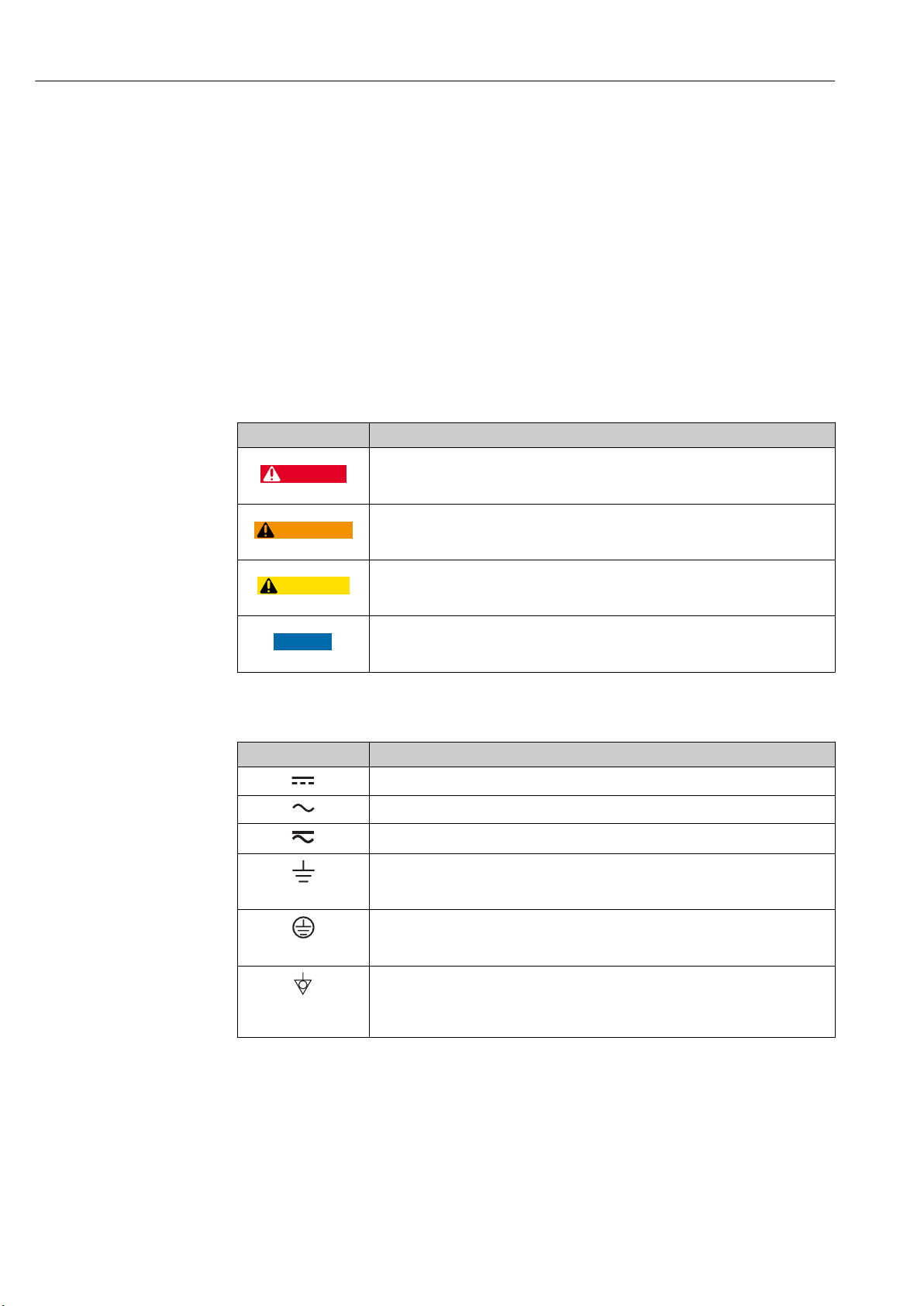
1.2 Symbols
1.2.1 Safety symbols
Symbol Meaning
DANGER!
This symbol alerts you to a dangerous situation. Failure to avoid this situation will
result in serious or fatal injury.
WARNING!
This symbol alerts you to a dangerous situation. Failure to avoid this situation can
result in serious or fatal injury.
CAUTION!
This symbol alerts you to a dangerous situation. Failure to avoid this situation can
result in minor or medium injury.
NOTE!
This symbol contains information on procedures and other facts which do not result in
personal injury.
1.2.2 Electrical symbols
Symbol Meaning
Direct current
Alternating current
Direct current and alternating current
Ground connection
A grounded terminal which, as far as the operator is concerned, is grounded via a
grounding system.
Protective ground connection
A terminal which must be connected to ground prior to establishing any other
connections.
Equipotential connection
A connection that has to be connected to the plant grounding system: This may be a
potential equalization line or a star grounding system depending on national or
company codes of practice.
4 Endress+Hauser
Page 5
Proservo NMS83 About this document
A
1.
1.
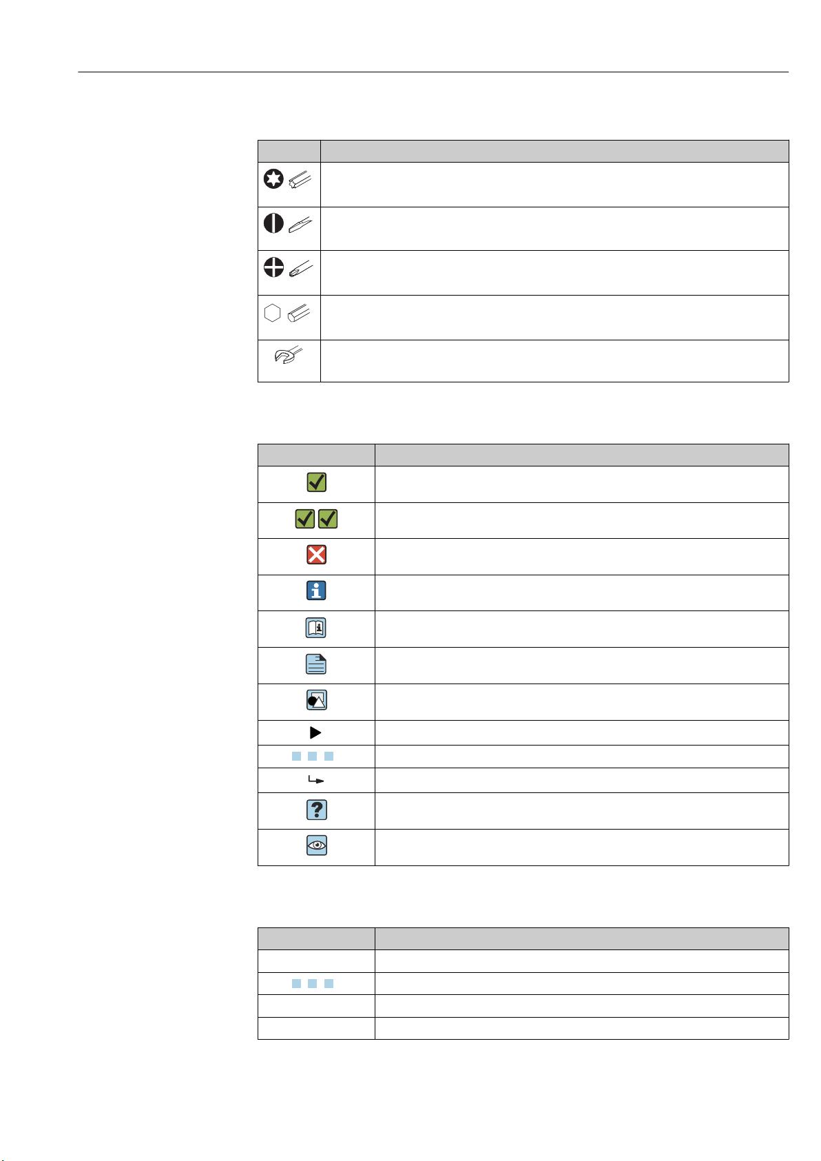
1.2.3 Tool symbols
Symbol Meaning
Torx screwdriver
A0013442
Flat blade screwdriver
A0011220
Cross-head screwdriver
A0011219
Allen key
A0011221
Hexagon wrench
A0011222
1.2.4 Symbols for certain types of information
Symbol Meaning
Permitted
Procedures, processes or actions that are permitted.
Preferred
Procedures, processes or actions that are preferred.
Forbidden
Procedures, processes or actions that are forbidden.
Tip
Indicates additional information.
Reference to documentation
Reference to page
Reference to graphic
Notice or individual step to be observed
, 2., 3.… Series of steps
Result of a step
Help in the event of a problem
Visual inspection
1.2.5 Symbols in graphics
Symbol Meaning
1, 2, 3 ... Item numbers
, 2., 3.… Series of steps
A, B, C, ... Views
A-A, B-B, C-C, ... Sections
Endress+Hauser 5
Page 6
About this document Proservo NMS83
-
.
Symbol Meaning
Hazardous area
Indicates a hazardous area.
Safe area (non-hazardous area)
Indicates the non-hazardous area.
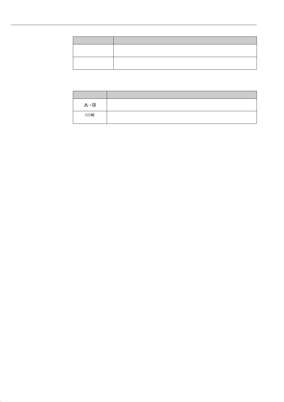
1.2.6 Symbols at the device
Symbol Meaning
Safety instructions
Observe the safety instructions contained in the associated Operating Instructions.
Temperature resistance of the connection cables
Specifies the minimum value of the temperature resistance of the connection cables.
6 Endress+Hauser
Page 7
Proservo NMS83 About this document
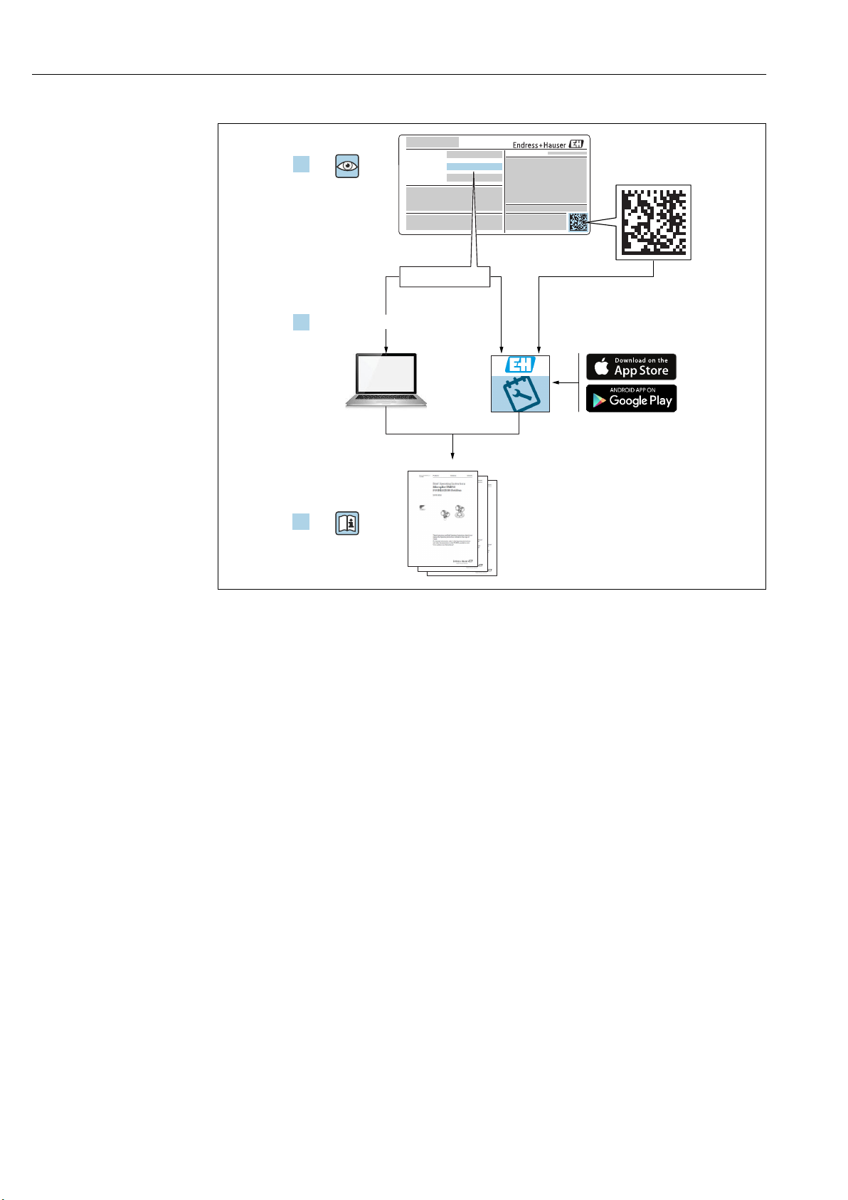
1.3 Documentation
For an overview of the scope of the associated Technical Documentation, refer to the
following:
• The W@M Device Viewer : Enter the serial number from the nameplate
(www.endress.com/deviceviewer)
• The Endress+Hauser Operations App: Enter the serial number from the nameplate
or scan the 2-D matrix code (QR code) on the nameplate.
1.3.1 Technical Information (TI)
The Technical Information contains all the technical data on the device and provides an
overview of the accessories and other products that can be ordered for the device.
Device Technical Information
Proservo NMS83 TI01250G
1.3.2 Brief Operating Instructions (KA)
The Brief Operating Instructions contain all the essential information from incoming
acceptance to initial commissioning.
Device Brief Operating Instructions
Proservo NMS83 KA01206G
1.3.3 Operating Instructions (BA)
The Operating Instructions contain all the information that is required in various phases of
the life cycle of the device: from product identification, incoming acceptance and storage,
to mounting, connection, operation and commissioning through to troubleshooting,
maintenance and disposal.
It also contains a detailed explanation of each individual parameter in the operating menu
(except the Expert menu). The description is aimed at those who work with the device
over the entire life cycle and perform specific configurations.
Device Operating Instructions
Proservo NMS83 BA01462G
1.3.4 Description of Device Parameters (GP)
The Description of Device Parameters provides a detailed explanation of each individual
parameter in the 2nd part of the operating menu: the Expert menu. It contains all the
device parameters and allows direct access to the parameters by entering a specific code.
The description is aimed at those who work with the device over the entire life cycle and
perform specific configurations.
Device Description of Device Parameters
Proservo NMS83 GP01080G
Endress+Hauser 7
Page 8

About this document Proservo NMS83
1.3.5 Safety instructions (XA)
Ordering feature 010 "Approval" Meaning XA
BC ATEX II 1/2G Ex db [ia Ga] IIC T6 Ga/Gb XA01495G
FD FM C/US XP-AIS Cl.I Div.1 Gr.BCD T6
AEx db [ia Ga] IIC T6 Ga/Gb
GC EAC Ga/Gb Ex db [ia Ga] IIC T6...T1 X XA01711G
IC IEC Ex db [ia Ga] IIC T6 Ga/Gb XA01495G
1)
KC
MC INMETRO Ex d[ia] IIC T6 Ga/Gb XA01705G
NC NEPSI Ex d[ia] IIC T6 Ga/Gb XA01704G
TC TIIS Ex d[ia] IIC T4 Ga/Gb XA01600G
1) KC approval is covered with IEC Ex approval.
KC Ex d[ia] IIC T6 Ga/Gb XA01495G
XA01496G
8 Endress+Hauser
Page 9

Proservo NMS83 About this document
1.4 Registered trademarks
FieldCare
Registered trademark of the Endress+Hauser Process Solutions AG, Reinach, Switzerland
MODBUS
Registered trademark of the MODBUS-IDA, Hopkinton, MA, USA
®
®
Endress+Hauser 9
Page 10

Basic safety instructions Proservo NMS83
2 Basic safety instructions
2.1 Requirements for the personnel
The personnel for installation, commissioning, diagnostics and maintenance must fulfill
the following requirements:
Trained, qualified specialists must have a relevant qualification for this specific function
‣
and task.
Are authorized by the plant owner/operator.
‣
Are familiar with federal/national regulations.
‣
Before starting work, read and understand the instructions in the manual and
‣
supplementary documentation as well as the certificates (depending on the
application).
Follow instructions and comply with basic conditions.
‣
The operating personnel must fulfill the following requirements:
Are instructed and authorized according to the requirements of the task by the facility's
‣
owner-operator.
Follow the instructions in this manual.
‣
2.2 Designated use
Application and measured materials
Depending on the version ordered, the measuring device can also measure potentially
explosive, flammable, poisonous and oxidizing media.
Measuring devices for use in hazardous areas, in hygienic applications or in applications
where there is an increased risk due to process pressure, are labeled accordingly on the
nameplate.
To ensure that the measuring device remains in proper condition for the operation time:
Only use the measuring device in full compliance with the data on the nameplate and
‣
the general conditions listed in the Operating Instructions and supplementary
documentation.
Check the nameplate to verify if the device ordered can be put to its intended use in the
‣
approval-related area (e.g. explosion protection, pressure vessel safety).
Use the measuring device only for media against which the process-wetted materials
‣
are adequately resistant.
If the measuring device is not operated at atmospheric temperature, compliance with
‣
the relevant basic conditions specified in the associated device documentation is
absolutely essential.
Protect the measuring device permanently against corrosion from environmental
‣
influences.
Observe the limit values in the "Technical Information".
‣
The manufacturer is not liable for damage caused by improper or non-designated use.
Residual risk
During operation the sensor may assume a temperature near the temperature of the
measured material.
Danger of burns due to heated surfaces!
For high process temperatures: Install protection against contact in order to prevent
‣
burns.
10 Endress+Hauser
Page 11

Proservo NMS83 Basic safety instructions
2.3 Workplace safety
For work on and with the device:
Wear the required personal protective equipment according to federal/national
‣
regulations.
2.4 Operational safety
Risk of injury.
Operate the device in proper technical condition and fail-safe condition only.
‣
The operator is responsible for interference-free operation of the device.
‣
Conversions to the device
Unauthorized modifications to the device are not permitted and can lead to unforeseeable
dangers.
If, despite this, modifications are required, consult with the manufacturer.
‣
Repair
To ensure continued operational safety and reliability,
Carry out repairs on the device only if they are expressly permitted.
‣
Observe federal/national regulations pertaining to repair of an electrical device.
‣
Use original spare parts and accessories from the manufacturer only.
‣
Hazardous area
To eliminate a danger for persons or for the facility when the device is used in the
hazardous area (e.g. explosion protection, pressure vessel safety):
Based on the nameplate, check whether the ordered device is permitted for the
‣
intended use in the hazardous area.
Observe the specifications in the separate supplementary documentation that is an
‣
integral part of these Instructions.
2.5 Product safety
This measuring device is designed in accordance with good engineering practice to meet
state-of-the-art safety requirements, has been tested, and left the factory in a condition in
which it is safe to operate. It meets general safety standards and legal requirements.
2.5.1 CE mark
The measuring system meets the legal requirements of the applicable EC guidelines. These
are listed in the corresponding EC Declaration of Conformity together with the standards
applied.
Endress+Hauser confirms successful testing of the device by affixing to it the CE mark.
Endress+Hauser 11
Page 12
Product description Proservo NMS83
2
1
3
4
5
6
7
8
2
3
4
9
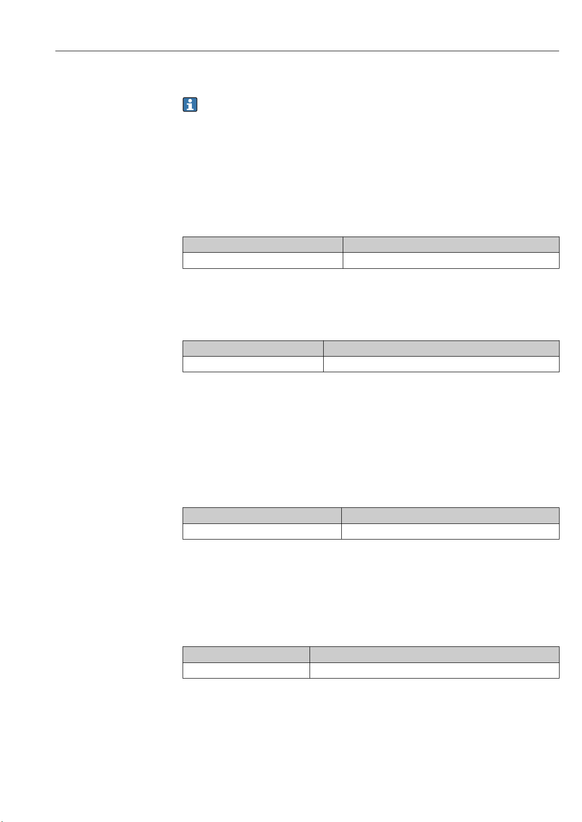
3 Product description
3.1 Product design
A0028699
1 Design of Proservo NMS83
1 Housing
2 Display and operating module (can be operated without opening the cover)
3 Process connection (Flange)
4 Displacer
2 Configuration of NMS83
1 Front cover
2 Display
3 Modules
4 Sensor unit
5 Housing
6 Wire drum
7 Bracket
8 Housing cover
9 Displacer
A0028873
12 Endress+Hauser
Page 13

Proservo NMS83 Incoming acceptance and product identification
4 Incoming acceptance and product
identification
4.1 Incoming acceptance
Upon receipt of the goods check the following:
• Are the order codes on the delivery note and the product sticker identical?
• Are the goods undamaged?
• Do the nameplate data match the ordering information on the delivery note?
• If required (see nameplate): Are the Safety Instructions (XA) enclosed?
If one of these conditions is not satisfied, contact your Endress+Hauser Sales Center.
4.2 Product identification
The following options are available for identification of the measuring device:
• Nameplate specifications
• Extended order code with breakdown of the device features on the delivery note
• Enter serial numbers from nameplates in W@M Device Viewer
( www.endress.com/deviceviewer ): All information about the measuring device is
displayed.
• Enter the serial number from the nameplates into the Endress+Hauser Operations App
or scan the 2-D matrix code (QR code) on the nameplate with the Endress+Hauser
Operations App: all the information for the measuring device is displayed.
For an overview of the scope of the associated Technical Documentation, refer to the
following:
• The W@M Device Viewer: Enter the serial number from the nameplate
(www.endress.com/deviceviewer)
• The Endress+Hauser Operations App: Enter the serial number from the nameplate or
scan the 2-D matrix code (QR code) on the nameplate.
Endress+Hauser 13
Page 14
Incoming acceptance and product identification Proservo NMS83
1
3
21
22
23
6
7
8
9
14
16
15
19
20
11
18
12
13
24
25
26
28
27
4
5
Ext. ord. cd.:
Order code:
Ser. no.:
Tp max.:
Mat.:
Date:
FW:
Dev.Rev.:
ex works
DeviceID:
Ta
Ta:
if modification
see sep. label
X =
MWP:
Tank ID:
Tank ref.height:
2
Density range:
Kg/m³
17
10
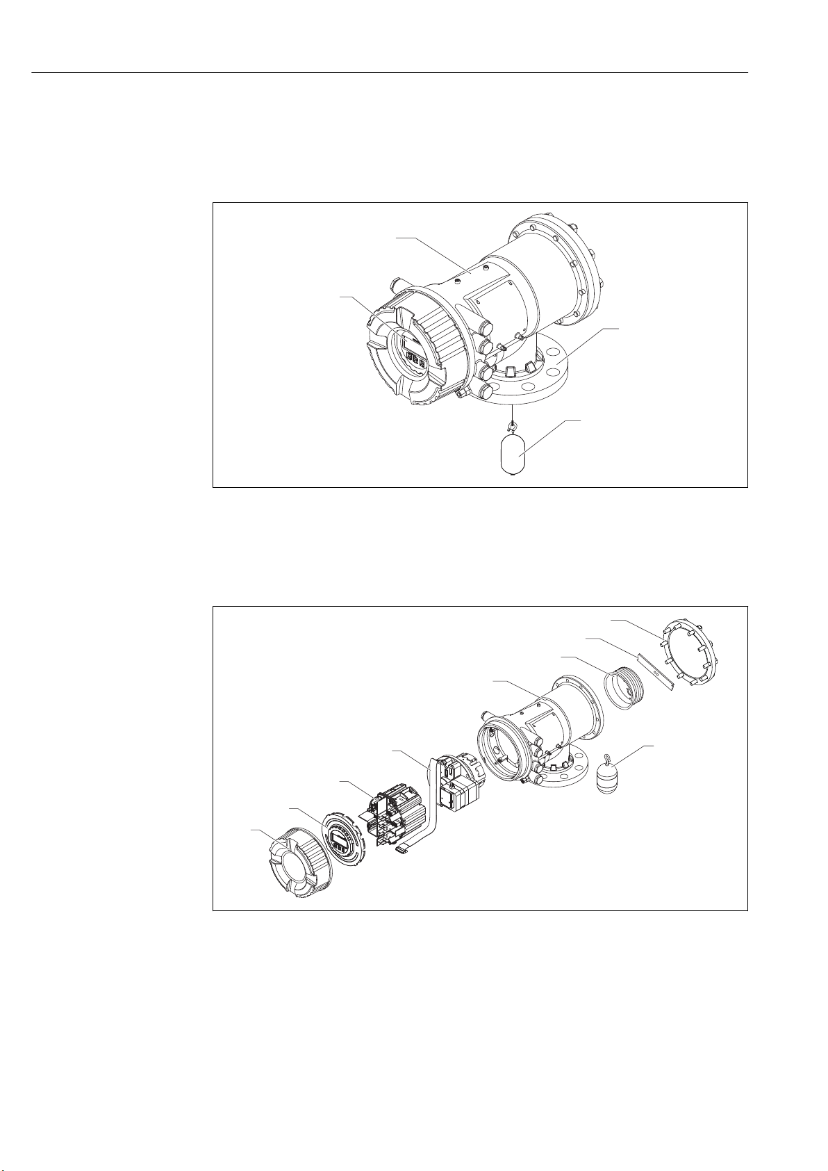
4.2.1 Nameplate
A0027791
3 Nameplate
1 Manufacturer address
2 Device name
3 Order code
4 Serial number
5 Extended order code
6 Supply voltage
7 Maximum process pressure
8 Maximum process temperature
9 Permitted ambient temperature (Ta)
10 Temperature resistance of cable
11 Thread for cable entry
12 Material in contact with process
13 Device ID
14 Firmware version
15 Device revision
16 Metrology certification numbers
17 Customized parametrization data
18 Ambient temperature range
19 CE mark / C-tick mark
20 Additional information on the device version
21 Ingress protection
22 Certificate symbol
23 Data concerning the Ex approval
24 General certificate of approval
25 Associated Safety Instructions (XA)
26 Manufacturing date
27 RoHS mark
28 QR code for the Endress+Hauser Operations App
14 Endress+Hauser
Page 15
Proservo NMS83 Incoming acceptance and product identification
Proservo NMS
&'./0
1234:
-20°C + °C~ 60
67:
89:;;<=び?@のBC、E/0をGわないでください。
PQRはT9をUVしないでください。
XY34 Z[のケーブルを`aしてください。85℃
&'67cdefg
hi
+,-$%(2)
"#$%
j"#$%
Qk
+,-$%(3)
lm$%(4)
lm$%(5)
lm$%(6)
no,-$%(1)(2)
no+-$%(1)(2)
lm$%(1)
lm$%(2)
lm$%(3)
,-$%(1)
+,-$%( )1
+,-$%(4)
'p qr 2s がu vし ない こと をy zし てか らT 9を
Uけ てく ださ い。
&'():NMS
XA01600G
Ex d[ia] IIC T4 Ga/Gb
エンドレスハウザー)
い た で8 9の を らな いで くだ さい 。
:
1
2
3
4
5
6
7
8
9
10
11
12
13
14
15
16
17
Endress+Hauser 15
A0032435
4 Nameplate Proservo NMS8x for TIIS
1 Product type
2 Ex type
3 Input/Output circuit (1)
4 Input/Output circuit (2)
5 Signal circuit (1)
6 Signal circuit (2)
7 Signal circuit (3)
8 Output circuit (1)
9 Power supply
10 Input/output circuit (3)
11 Input/output circuit (4)
12 Signal circuit (4)
13 Signal circuit (5)
14 Signal circuit (6)
15 Contact output circuit (1) (2)
16 Contact input circuit (1) (2)
17 Drawing number
4.2.2 Manufacturer address
Endress+Hauser SE+Co. KG
Hauptstraße 1
79689 Maulburg, Germany
Address of the manufacturing plant: See nameplate.
4.3 Storage and transport
4.3.1 Storage conditions
• Storage temperature: –50 to +80 °C (–58 to +176 °F)
• Store the device in its original packaging.
Page 16

Incoming acceptance and product identification Proservo NMS83
4.3.2 Transport
NOTICE
Risk of injury
Transport the measuring device to the measuring point in its original packaging.
‣
Take into account the mass center of the device in order to avoid unintended tilting.
‣
Comply with the safety instructions, transport conditions for devices over 18kg
‣
(39.6lbs) (IEC61010).
16 Endress+Hauser
Page 17
Proservo NMS83 Installation
5 Installation
5.1 Requirements
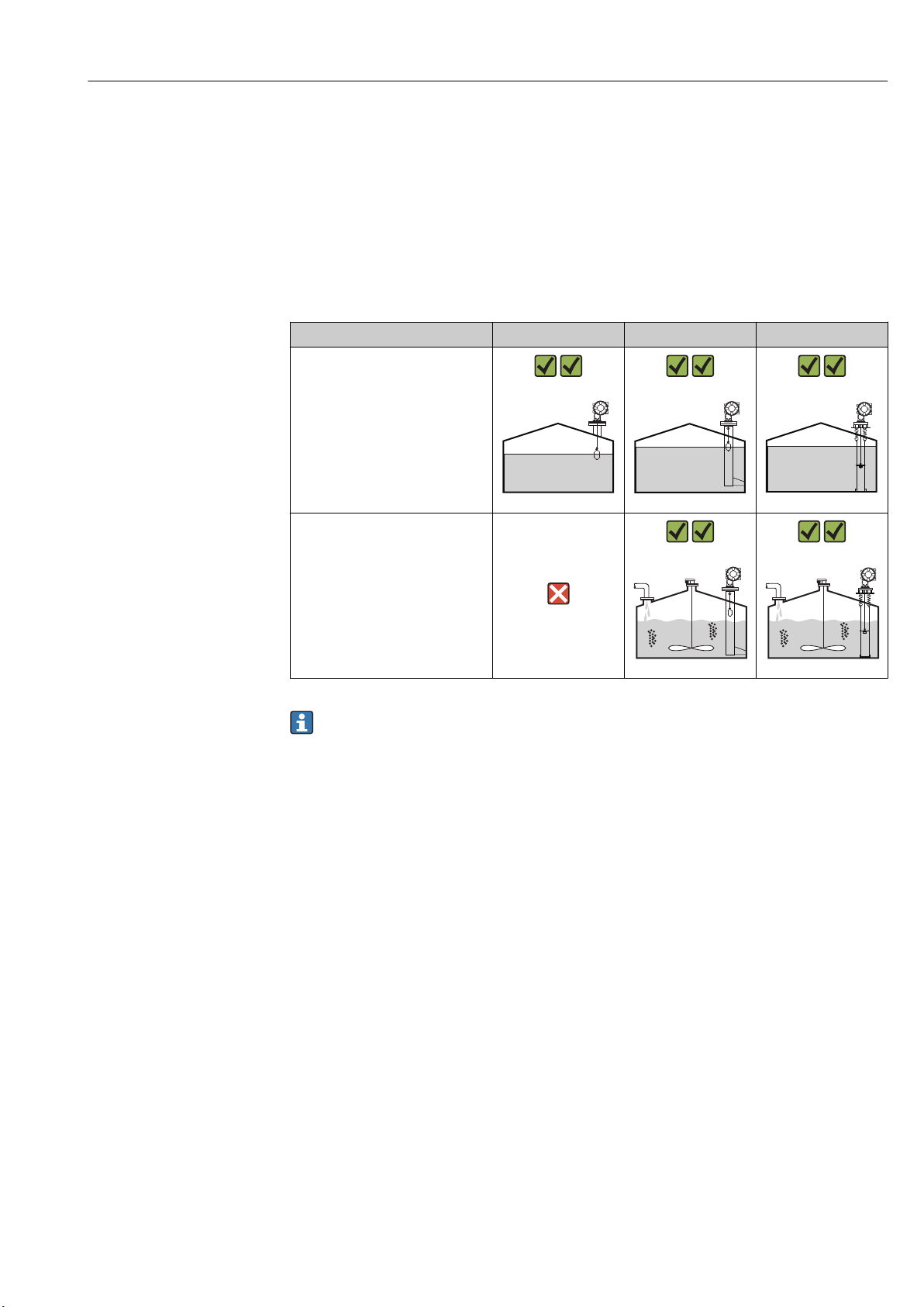
5.1.1 Type of tanks
Depending on the type of tank and application, different installation procedures are
recommended for NMS8x.
Type of tanks Without guide system With stilling well With guide wires
Fixed roof tank
A0032437 A0032438 A0032439
Tank with agitator or heavy
turbulence
A0032440 A0032441
• A stilling well is required in a floating roof tank and a covered floating roof tank.
• Guide wires cannot be installed in a floating roof tank. When the measuring wire is
exposed to free space, it may break due to an external shock.
• Installing guide wires is not allowed in pressurized tanks because the wires would
prevent closing the valve for replacing the wire, wire drum, or displacer. NMS8x
installation position is important for applications without the guide wire system in
order to prevent the measuring wire from being broken (refer to Operating
Instructions for details ).
Endress+Hauser 17
Page 18
Installation Proservo NMS83
3
4
1
2
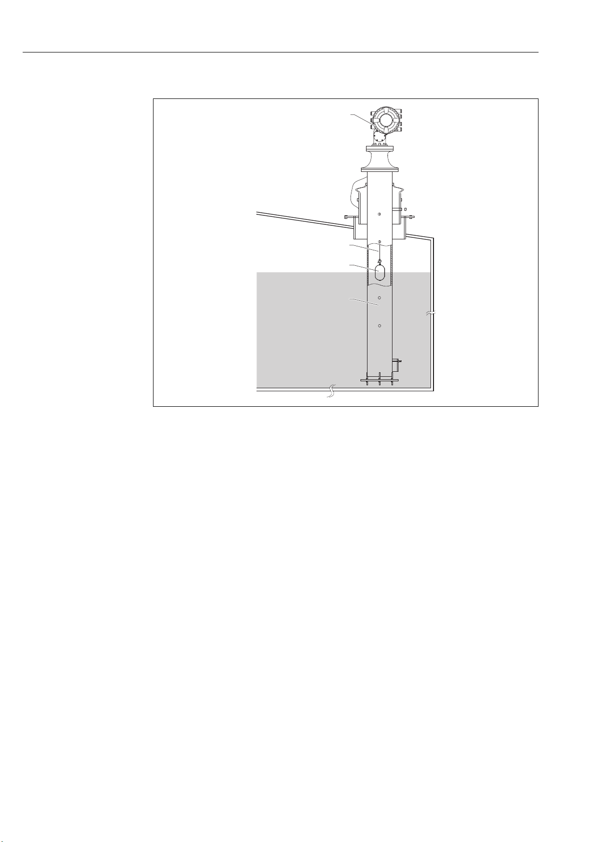
Typical tank installation
A0026904
5 Typical tank installation 1
1 NMS8x
2 Measuring wire
3 Displacer
4 Stilling well
18 Endress+Hauser
Page 19
Proservo NMS83 Installation
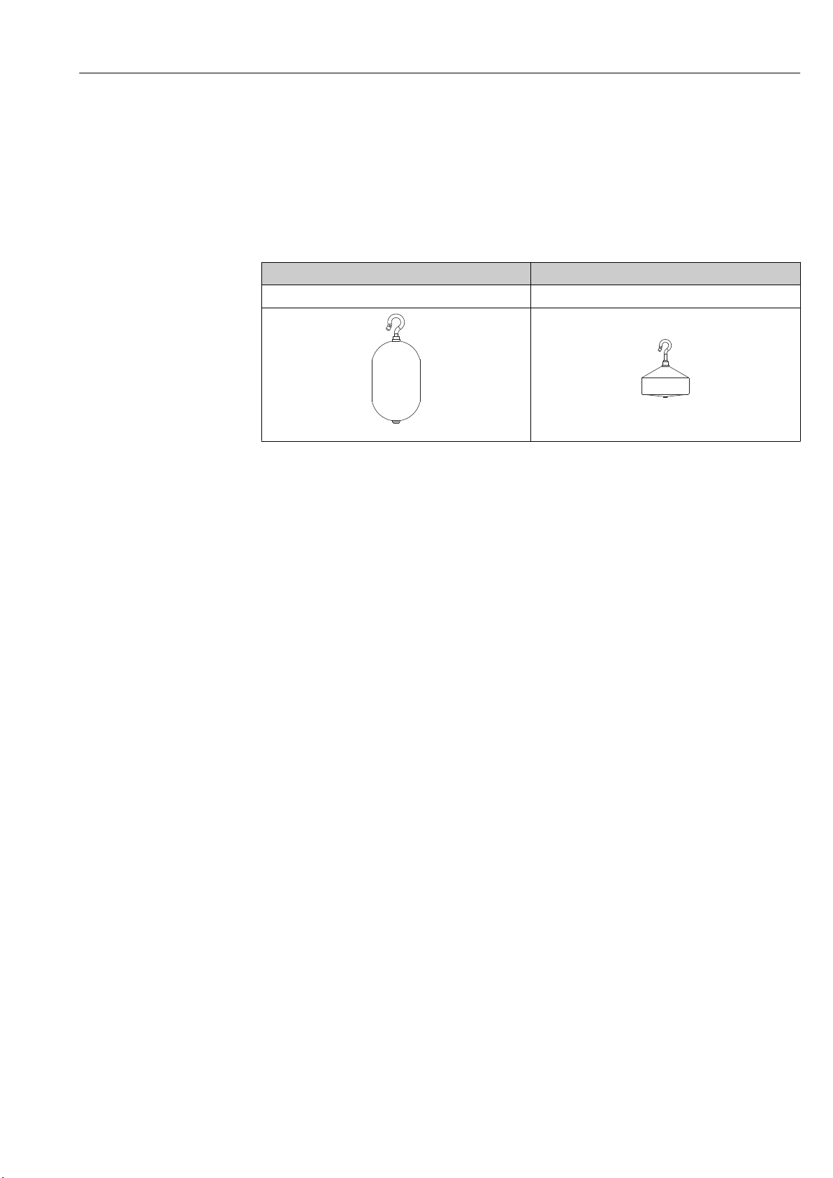
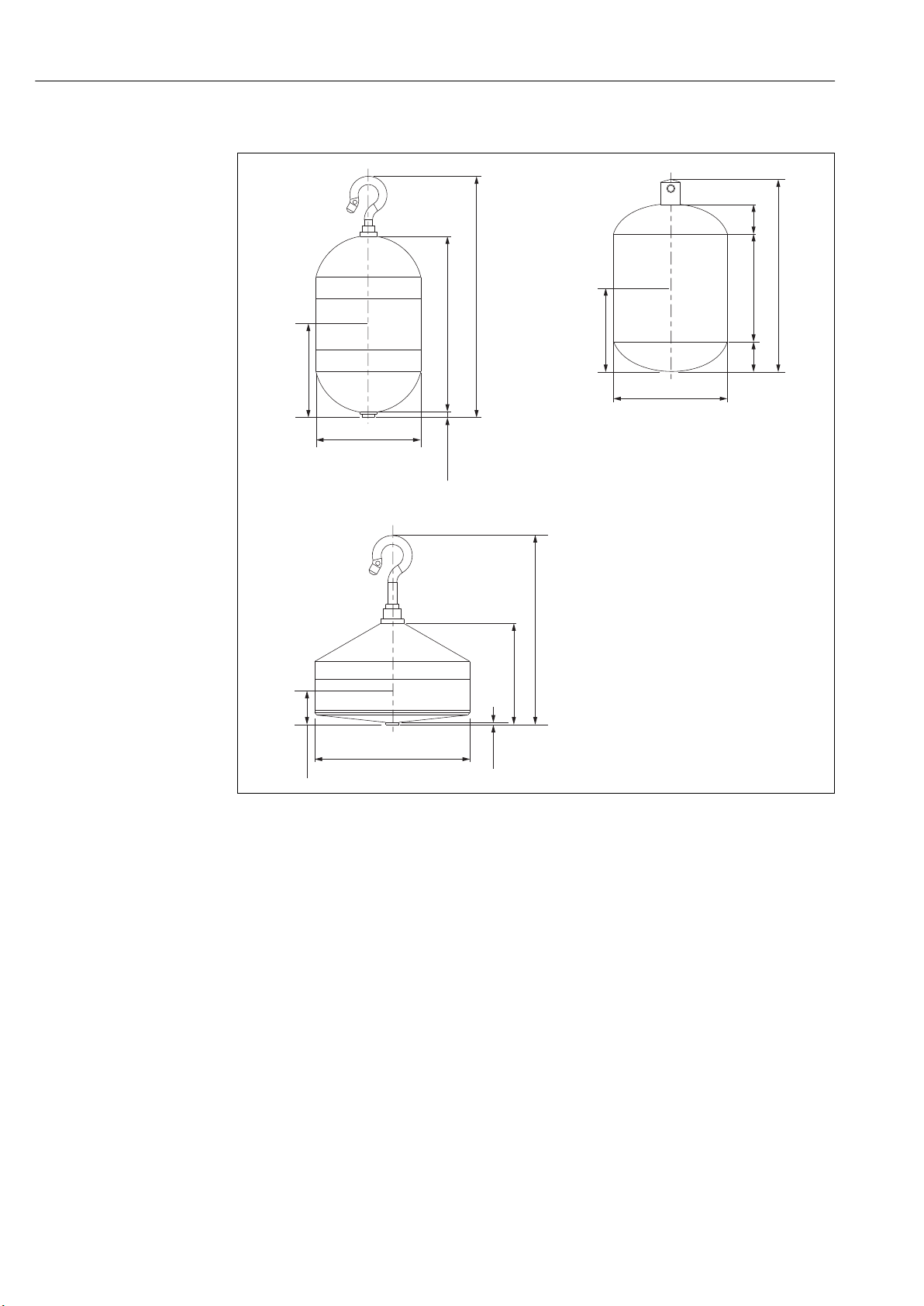
5.1.2 Displacer selection guide
A wide variety of displacers are available to suit different application. Proper displacer
selection ensures optimal performance and longevity. The following guidelines will assist
you in selecting the most suitable displacer for your application.
Displacer types
The following NMS8x displacers are available.
50 mm (1.97 in) 70 mm (2.76 in)
316L/PTFE 316L
A0032430
A0032429
Endress+Hauser 19
Page 20
Installation Proservo NMS83
A
Ø50.8 (2)
a
45 (1.77)
85 (3.35)
116.6 (4.59)
2.5 (0.09)
B
Ø50 (1.97)
a
35 (1.38)
82.7 (3.26)
46.7 (1.84)
11.5
(0.45)
11.5
(0.45)
C
17 (0.67)
46.6 (1.83)
1 (0.03)
90 (3.54)
Ø70(2.76)
a
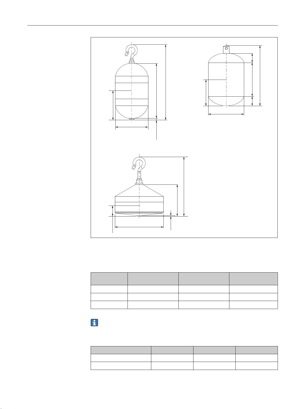
Displacer dimensions
A ⌀50 mm (1.97 in) 316L cylindrical displacer
B ⌀50 mm (1.97 in) PTFE cylindrical displacer
C ⌀70 mm (2.76 in) 316L conical displacer
a Immersion point
A0029581
20 Endress+Hauser
Page 21
Proservo NMS83 Installation
A
Ø50.8 (2)
a
45 (1.77)
85 (3.35)
116.6 (4.59)
2.5 (0.09)
B
Ø50 (1.97)
a
35 (1.38)
82.7 (3.26)
46.7 (1.84)
11.5
(0.45)
11.5
(0.45)
C
17 (0.67)
46.6 (1.83)
1 (0.03)
90 (3.54)
Ø70(2.76)
a
A ⌀50 mm (1.97 in) 316L cylindrical displacer
B ⌀50 mm (1.97 in) PTFE cylindrical displacer
C ⌀70 mm (2.76 in) 316L conical displacer
a Immersion point
Item
Weight (g) 253 250 245
Volume (ml) 143 118 124
Balance volume (ml) 70.7 59 52.8
⌀50 mm (1.97 in) 316L
cylindrical displacer
The weight, volume, and balance volume are individually determined by each
displacer and also might vary depending on the values stated above.
Recommended displacer by application
Application Product level Interface level Density
Viscous liquid 50 mm (1.97 in) PTFE Not Recommended Not Recommended
Not viscous liquid (e.g. alcohol) 50 mm (1.97 in) 316L 50 mm (1.97 in) 316L 50 mm (1.97 in) 316L
⌀50 mm (1.97 in) PTFE
cylindrical displacer
A0029581
⌀70 mm (2.76 in) 316L
conical displacer
Endress+Hauser 21
Page 22
Installation Proservo NMS83
1
d
D
1
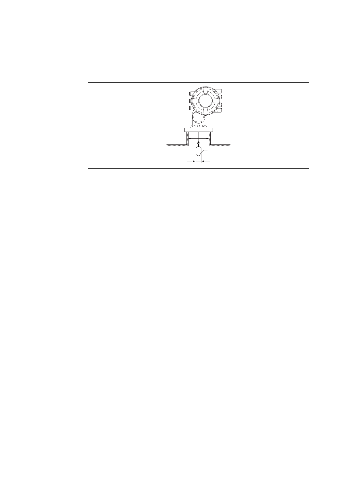
5.1.3 Mounting without a guide system
NMS8x is mounted on a nozzle of the tank roof without a guide system. Sufficient
clearance inside the nozzle is necessary to allow the displacer to move without hitting the
inner walls (for details of D, → 23).
A0026908
6 No guide system
D1Inner diameter of the tank nozzle
d Diameter of the displacer
1 Displacer
22 Endress+Hauser
Page 23
Proservo NMS83 Installation
L
1
L
2
L
1
L
2
A
B
L
3
L
3
D
2
D
1
d
r
D
1
d
D
2
p(L )x
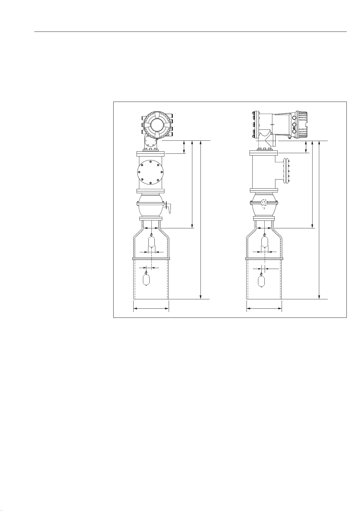
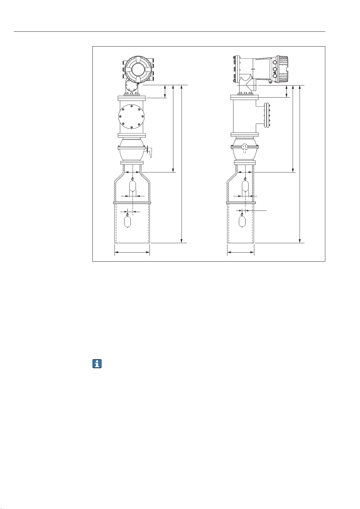
5.1.4 Mounting with a stilling well
The stilling well diameter that is required to protect the measuring wire without disturbing
its operation varies depending on the tank height. The stilling well could either be of
constant diameter, or narrower at its upper part and wider at its lower part. The following
figure shows two examples of the latter case, namely a concentric stilling well and an
asymmetric stilling well.
A0029574
7 Mounting with concentric stilling well
A Front view
B Side view
L1Length from the center of the calibration window to the upper part of the stilling well
L2Length from the center of the calibration window to the bottom of the stilling well
L3Length from the center of the calibration window to the bottom of the flange
D1Diameter of upper part of stilling well
D2Diameter of stilling well
d Diameter of displacer
p
Longitudinal wire position from the center of the flange
(Lx)
r Radial direction offset
Endress+Hauser 23
Page 24
Installation Proservo NMS83
L
1
L
2
L
1
L
2
A
B
L
3
L
3
D
2
D
1
d
r
D
1
d
D
2
p (L )x
A0026909
8 Mounting with asymmetric stilling well
A Front view
B Side view
L1Length from the center of the calibration window to the upper part of the stilling well
L2Length from the center of the calibration window to the bottom of the stilling well
L3Length from the center of the calibration window to the bottom of the flange
D1Diameter of upper part of stilling well
D2Diameter of stilling well
d Diameter of displacer
p
Longitudinal wire position from the center of the flange
(Lx)
r Radial direction offset
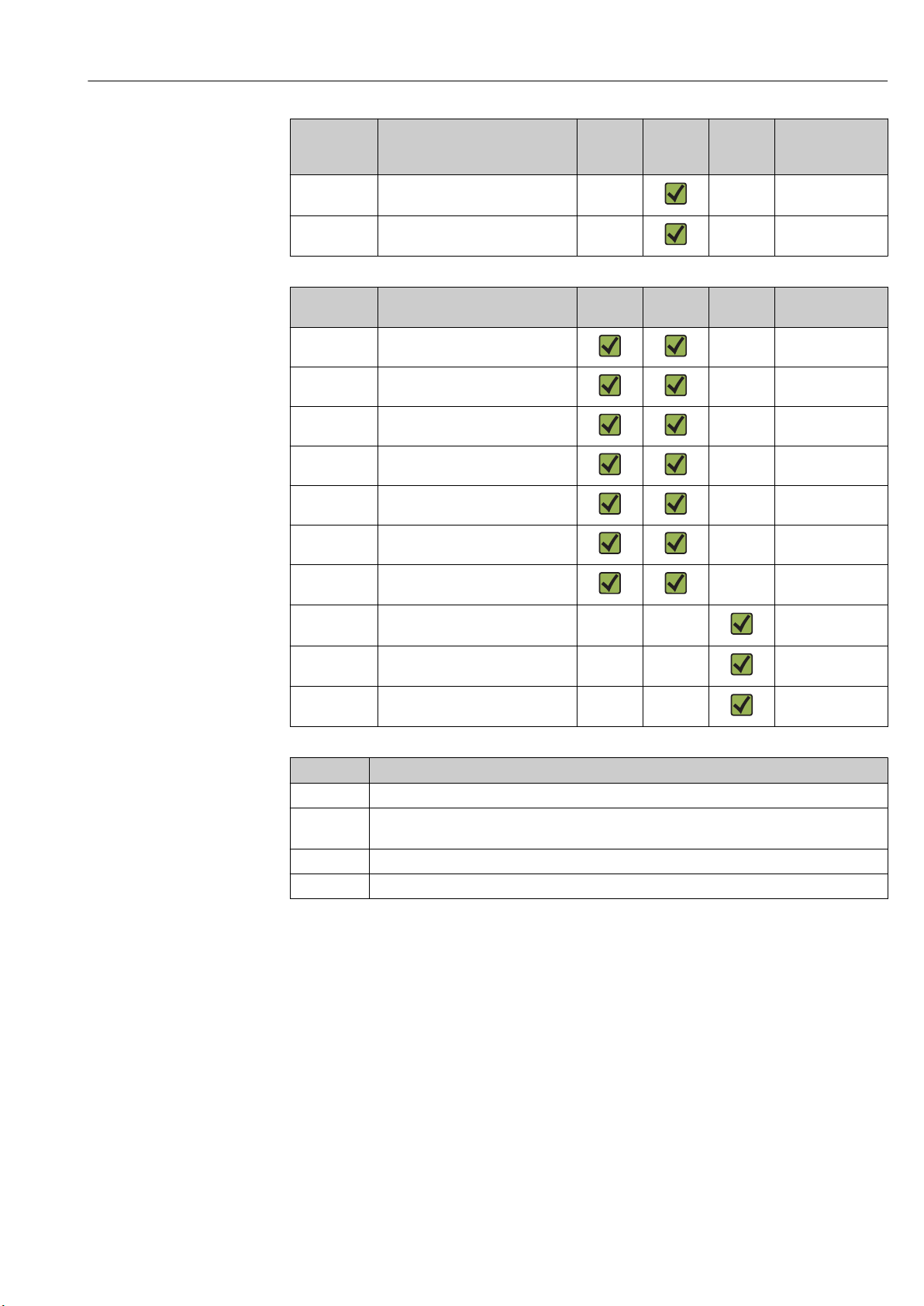
• L3: length from center of the calibration window to the bottom of the flange
(77 mm (3.03 in) + flange thickness).
For JIS 10K 150A RF, the flange thickness is 22 mm (0.87 in).
• When using an asymmetric stilling well, take into account the lateral shift of the
displacer and follow the NMS8x mounting direction as shown in the figure.
• To calculate the required stilling well diameters, the formula below should be used.
The following tables contain the necessary parameters in order to calculate the
dimensions of the stilling well. Be sure to have appropriate dimensions of the
stilling well according to each dimension in the table.
• The radial direction offset (r) is required for only the 47 m (154.20 ft) and
55 m (180.45 ft) wire drum. For all other drums, the offset is 0 mm/in.
24 Endress+Hauser
Page 25
Proservo NMS83 Installation
Feature: 110 Description
(Measuring range; Wire;
Diameter)
G1
H1
Feature: 120 Description
1AA 316L; 30 mm (1.18 in) cylindrical 30 mm (1.18 in)
1AC 316L; 50 mm (1.97 in) cylindrical 50 mm (1.97 in)
1BE 316L; 70 mm (2.76 in) conical 70 mm (2.76 in)
1BJ 316L;110 mm (4.33 in) conical 110 mm (4.33 in)
2AA PTFE; 30 mm (1.18 in) cylindrical 30 mm (1.18 in)
2AC PTFE; 50 mm (1.97 in) cylindrical 50 mm (1.97 in)
3AC AlloyC276; 50 mm (1.97 in)
4AC 316L polished; 50 mm (1.97 in)
4AE 316L polished; 70 mm (2.76 in)
5AC PTFE; 50 mm (1.97 in) cylindrical,
47 m (154.20 ft); 316L;
0.15 mm (0.00591 in)
55 m (180.45 ft); 316L
0.15 mm (0.00591 in)
(Displacer material; Type)
cylindrical
cylindrical
conical
hygienic white
NMS80 NMS81 NMS83 r
6 mm (0.24 in)
6 mm (0.24 in)
NMS80 NMS81 NMS83 d
50 mm (1.97 in)
50 mm (1.97 in)
70 mm (2.76 in)
50 mm (1.97 in)
Parameter Description
d Diameter of displacer
p(Lx) Longitudinal wire position from the center of the flange
The value can be determined by using following graph.
r Radial direction offset
s Safety factor recommended: 5 mm (0.197 in)
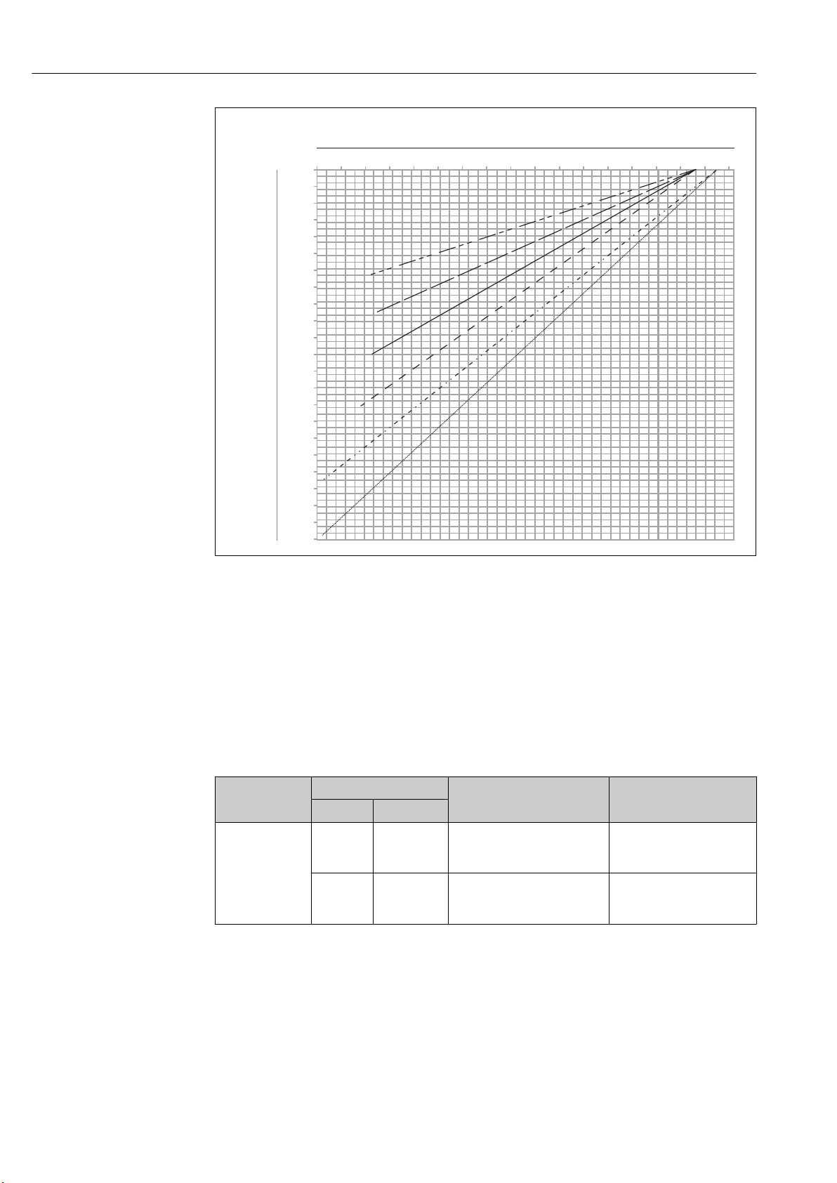
The following graph shows the lateral shift of the displacer depending on the measured
distance for the different wire drums.
Endress+Hauser 25
Page 26
Installation Proservo NMS83
L , L (mm) ( )
1 2
in
p (Lx) (mm) ( )in
-1.4 -1.3 -1.2 -1.1 -1.0 -0.9 -0.8 -0.7 -0.6 -0.5 -0.4 -0.3 -0.2 -0.1 0.0 0.1 0.2 0.3
0
100
200
300
400
500
600
700
800
900
1000
1100
1200
1300
1400
1500
1600
1700
1800
1900
2000
2100
2200
0
2000
4000
6000
8000
10000
12000
14000
16000
18000
20000
22000
24000
26000
28000
30000
32000
34000
36000
38000
40000
42000
44000
46000
48000
50000
52000
54000
56000
-36 -32 -28 -24 -20 -16 -12 -8 -4 0 4 8
a
d
e
c
b
f
9 Lateral shift of displacer according to measurement range
a 16 m (A3) (NMS80/NMS81/NMS83)
b 22 m (C2) (NMS80/NMS81/NMS83)
c 28 m (D1) (NMS80/NMS81)
d 36 m (F1) (NMS80/NMS81)
e 47 m (G1) (NMS81)
f 55 m(H1) (NMS81)
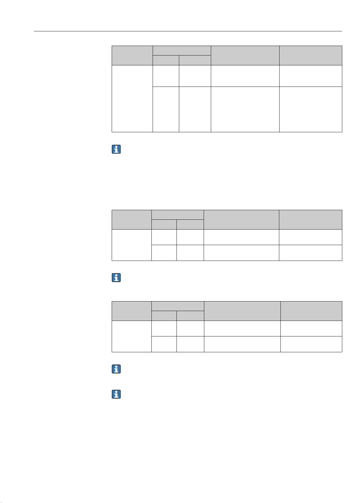
Upper diameter of stilling well
The dimension of D1 has to be the largest value of the dimensions D1a, D1b , D1c, and D
according to the following formula.
26 Endress+Hauser
D1 Dimension
(Example)
>68.1 mm
(2.68 in)
D
Dimension
1x
Example Parameter
68.1 mm
(2.68 in)
65.6 mm
(2.58 in)
D
1a
D
1b
Description Formula
D1 dimension when the
displacer is at the center of the
calibration window
D1 dimension when the
displacer is at the upper part of
the stilling well
= 2 x ( |p (0)|+ d/2 + s)
= 2 x (|p (L1)|+ d/2 + s)
A0027997
1d
Page 27
Proservo NMS83 Installation
D1 Dimension
(Example)
D
Dimension
1x
Example Parameter
50.9 mm
(2.00 in)
D
1c
D
1d
Description Formula
D1 dimension when the
displacer is at the bottom of the
stilling well
D1 dimension when the radial
direction offset is considered.
This calculation is used only
with the 47 m (154.20 ft) wire
drum (G1 in Feature110) and
55 m (180.45 ft) (H1 in feature
110)
= 2 x ( |p (L2)|+ s)
= 2 x (d/2 + r + s)
Example: L1 = 1 000 mm, L2 = 20 000 mm, d = 50 mm, s = 5.0, 28 m drum
Lower diameter of stilling well
The dimension of D2 has to be the larger value of the dimensions D1 and D2b .
See the table below.
Concentric pipe
D2 Dimension
(Example)
>100.9 mm
(3.97 in)
D2x Dimension
Example Parameter
68.1 mm
(2.68 in)
100.9 mm
(3.97 in)
D
1
D
2b
Description Formula
Calculated D1 value
D2 dimension when the displacer is
in L2 length
= 2 x (|p (L2)| + d/2 + s)
Example: L2 = 20 000 mm, d = 50 mm, s = 5.0, 28 m drum
Asymmetric pipe
D2 Dimension
(Example)
>84.5 mm
(3.33 in)
D2x Dimension
Example Parameter
68.1 mm
(2.68 in)
84.5 mm
(3.33 in)
D
1
D
2b
Description Formula
Calculated D1 value
D2 dimension that the displacer can
pass through (nth groove)
= |p (L2)| + d/2 + s + D1/2
Example: L2 = 20 000 mm, d = 50 mm, s = 5.0, 28 m drum
Recommendations for NMS8x mounting with a stilling well
Follow the recommendations for mounting NMS8x with a stilling well.
• Keep the pipe connection welds smooth.
• When drilling holes into the pipe, keep the interior surface of the holes clear of
metal chips and burrs.
• Keep the pipe as vertical as possible. Check using a plumb bob.
• Install the asymmetric pipe under the valve and align the centers of the NMS8x and
the valve.
• Set the center of the lower part of the asymmetric pipe in the direction of the lateral
motion.
• Observe the recommendations as per API MPMS chapter 3.1B.
• Confirm grounding between NMS8x and the tank nozzle.
Endress+Hauser 27
Page 28
Installation Proservo NMS83
+1°
-1°
1
5.1.5 Alignment of NMS8x
Flange
Confirm that the size of the nozzle and the flange is matched prior to mounting NMS8x on
the tank. The flange size and the rating of NMS8x vary depending on the customer’s
specifications.
• Check the flange size of NMS8x.
• Mount the flange on the top of the tank. The deviation of the flange from the
horizontal plane should not exceed +/- 1 degree.
• When mounting NMS8x on a long nozzle, make sure that the displacer does not
touch the inner wall of the nozzle.
10 Allowable inclination of mounting flange
1 Nozzle
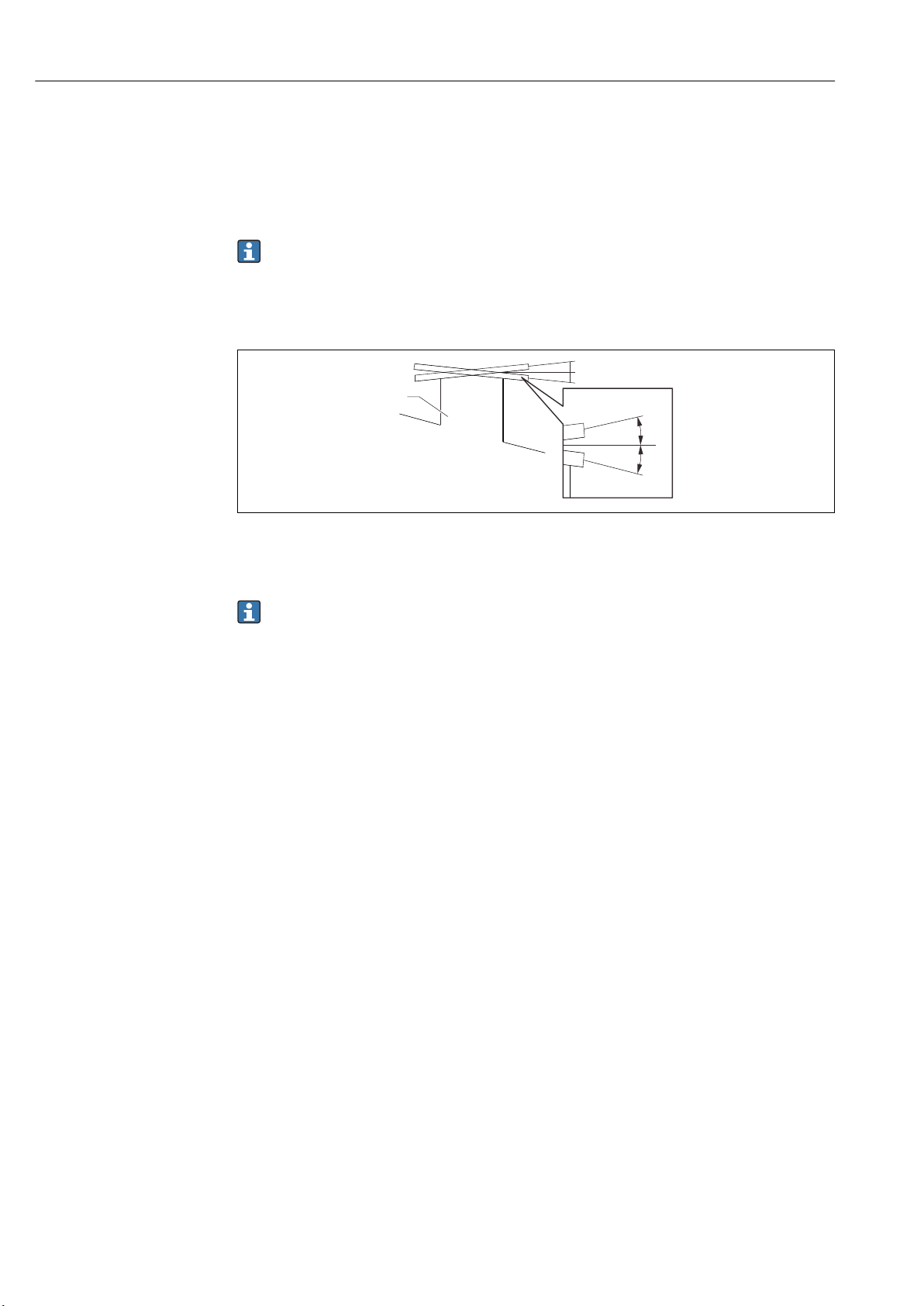
When NMS8x is installed without a guide system, follow the recommendations below:
• Confirm the mounting nozzle is in the sector between 45 and 90 degrees (or -45
and -90 degrees)away from the inlet pipe of the tank. This prevents heavy swinging
of the displacer caused by waves or turbulence from the inlet liquid.
• Confirm the mounting nozzle is 500 mm (19.69 in) or more away from the tank
wall.
• Confirm the minimum measuring level is at 500 mm (19.69 in) or more above the
top of the inlet pipe by setting the low stop (for details of low stop setting,
→ 89). This protects the displacer from direct flow of the inlet liquid.
• If a stilling well cannot be mounted in the tank due to the shape or condition of the
tank, attaching a guide system is recommended. Consult E+H services for further
information.
A0026889
28 Endress+Hauser
Page 29
Proservo NMS83 Installation
≥500 (19.69)
90°-90°
0°
45°-45°
1
1
≥500 (19.69)
2
2
A0026890
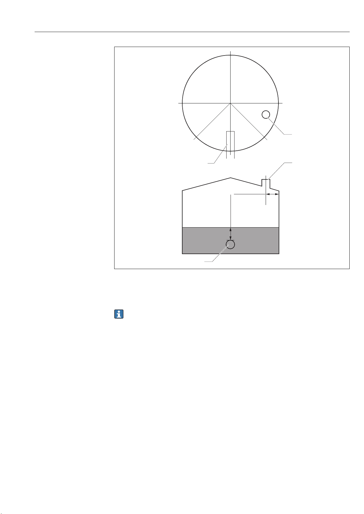
11 Recommended position for mounting NMS8x and minimum measuring level; dimensions mm (in)
1 Inlet pipe
2 Tank nozzle
• Before pouring liquid into the tank, confirm that liquid flowing through the inlet of
the pipe will not contact the displacer directly.
• When discharging liquid out of the tank, ensure that the displacer will not get
caught in the liquid current and sucked into the outlet pipe.
5.1.6 Electrostatic charge
When liquid measured by NMS8x has a conductivity of 1 uS/m or less, it is quasinonconductive. In this case, using a stilling well or guide wire is recommended. This
releases the electrostatic charge on the liquid surface.
Endress+Hauser 29
Page 30
Installation Proservo NMS83
5.2 Mounting of the device
When NMS8x is delivered, the displacer is always shipped separately and there are two
methods to install displacer as follows.
• Installation for displacer shipped separately method
• Installation through the calibration window
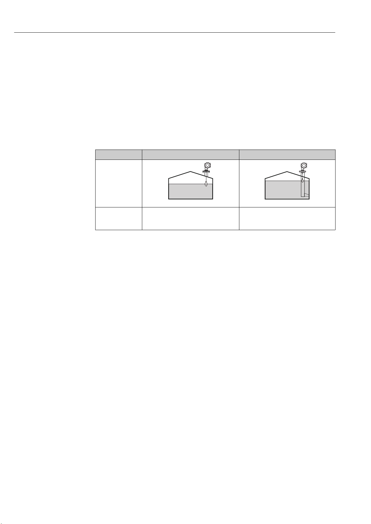
5.2.1 Available installations
The following installation procedures are available for NMS8x.
• Mounting without guide system
• Mounting with stilling well
Mounting options Free-space mounting With stilling well
Type of tanks
A0032437 A0032438
Type of installations • Displacer shipped separately
• Displacer installation through calibration
window
• Displacer shipped separately
• Displacer installation through calibration
window
30 Endress+Hauser
Page 31

Proservo NMS83 Installation
316L
50
ml
70.8
ml
141.6
g
256.6
Ø
B
V
D
V
D
m
NMS8
Displacer
12345678901
Ser.no.:
712xxxxx
Spare part-no.:
HNBR
O-Ring
28m
Range
NMS8
98765432109
Ser. no.:
3
1.
2.
12345678901
712xxxxx
m 256.6g
D
V 141.6mL
D
V 70.8mL
B
!50 316L
Spare part-no.: 712xxxxx
mm
302.xxx
Cir.
NMS8
Wiredrum
98765432109
Ser.no.:
1.35g/10m
HNBR
28 m
WireWgt.
O-Ring
Range
Spare part-no.: 712xxxxx
5.2.2 Verification of displacer and wire drum
Prior to installation of NMS8x, confirm that the serial numbers of displacer and the wire
drum match with those printed to the label attached on the housing.
Endress+Hauser 31
12 Verification of displacer and wire drum
A0029470
Page 32

Installation Proservo NMS83
A
5.2.3 Tools to be required for installation
The following tools are required when installing NMS8x.
Tools Figures Notes
Box end wrench Use the following size
• 24 mm (0.94 in)
• 26 mm (1 in)
• 30 mm (1.2 in)
• 32 mm (1.3 in)
Crescent wrench Use the size of 350 mm (13.78 in)
Allen key Use the size of 3 mm (0.12 in)or 5 mm (0.17 in)
Screw driver
• Cross-head screwdriver
• Flat-blade screwdriver
Wire cutters or terminal
pliers
Crimp terminal
Water pump pliers
Density calibration test
weight
A:
Signal and power supply:
0.2 to 2.5 mm2 (24 to 13 AWG)
• Ground terminal in the terminal
compartment: max. 2.5 mm2 (13 AWG)
• Ground terminal at the housing: max.
4 mm2 (11 AWG)
This tool is used especially for density
measurement application (optional).
32 Endress+Hauser
Page 33

Proservo NMS83 Installation
1.
200 (7.87)
200 (7.87)
130 (5.12) 130 (5.12)
2.
3.
3
1
2
6
4
4.
5.
6.
7.
8.
9.
5.2.4 Installation for displacer shipped separately method
It is necessary to remove the wire drum from NMS8x, remove the tape on the wire drum,
mount the wire drum in the drum housing, and install the displacer on the measuring
wire.
Use blocks or a pedestal to secure NMS8x and provide an environment where electrical
power can be supplied to NMS8x.
The following procedure uses NMS81 figures for an example.
Displacer is shipped separately according to the following specifications.
• 47 m (154.2 ft) measuring range
• 55 m (180.5 ft) measuring range
• 110 mm (4.33 in) measuring range
• 8 in flange
• Cleaned from oil+grease option
Procedures Figures
Secure NMS8x on the blocks or pedestal.
Confirm that there is enough space under NMS8x.
Be careful not to drop NMS8x.
Remove screws and M6 bolts [6] (M10 bolts for stainless
steel housing).
Remove the wire drum cover [5], wire drum stopper [4],
and the bracket [2].
Remove the wire drum [1] from the drum housing.
Remove the tape [3] on the wire drum.
Unwind the measuring wire approximately
250 mm (9.84 in) so that the wire ring is positioned
under the flange.
Mount the wire drum on NMS8x.
Mount the bracket.
• Take special care to not hit the wire drum against the
housing due to strong magnet force.
• Handle the measuring wire with care. It may kink.
• Be sure that the wire is wound correctly in the grooves.
A0032442
Dimensions mm (in)
A0028876
Endress+Hauser 33
Page 34

Installation Proservo NMS83
10.
1
3
2
11.
2
3
4
1
12.
13.
14.
15.
16.
17.
1
18.
19.
20.
Procedures Figures
Hook the displacer [3] on the ring [2].
• Be sure that the wire is wound correctly in the grooves.
• If not, remove the displacer and the wire drum, and
repeat step 7.
A0029116
Turn on the power of NMS8x.
Perform sensor calibration
Secure the displacer [2] to the measuring wire [1] using
the securing wire [3].
Perform reference calibration.
Turn off the power.
Mount the wire drum cover [4].
• For sensor calibration, → 82
• For reference calibration, → 84.
Mount NMS8x on the tank nozzle [1].
Confirm that the displacer does not touch the inner wall
of the nozzle.
Turn on the power.
Perform drum calibration.
For drum calibration, → 85
A0027017
A0028877
34 Endress+Hauser
Page 35

Proservo NMS83 Installation
1.
1
2.
2
1
3
4
6
3.
4.
5.
6.
3
4
2
1
7.
8.
9.
10.
1
2
3
11.
12.
5.2.5 Installation through the calibration window
In the case of a 50 mm (1.97 in) diameter displacer, the displacer can be installed through
the calibration window.
It is only possible to install the following displacers through the calibration window:
50 mm SUS, 50 mm alloy C, 50 mm PTFE
The following procedure uses NMS81 figures for an example.
Procedures Figures
Remove the calibration window cover [1].
A0032443
Remove M6 bolts and screws [6] (M10 bolts for stainless
steel housing).
Remove the cover [5], wire drum stopper [4], and the
bracket [3].
Remove the wire drum [1] from the drum housing.
Remove the tape [2] that is securing the wire.
Handle the measuring wire with care. It may kink.
Holding the wire drum [1] with one hand, unwind the
measuring wire [3] approximately 500 mm (19.69 in).
Secure the wire [3] temporarily with the tape [2].
Insert the wire ring [4] into the drum housing.
Pull the wire ring out through the calibration window.
• Take special care to not hit the wire drum against the
housing due to strong magnet force.
• Handle the measuring wire with care.
Insert the wire drum [3] temporarily into the drum
housing.
Hook the displacer [2] on the wire ring.
Secure the displacer to the measuring wire using the
securing wire [1].
Handle the measuring wire with care. It may kink.
A0029118
A0028879
A0027984
Endress+Hauser 35
Page 36

Installation Proservo NMS83
13.
2
1
14.
15.
16.
17.
3
4
5
2
1
18.
19.
20.
21.
22.
23.
24.
25.
Procedures Figures
Remove the wire drum from the drum housing and
unwind the measuring wire down approximately
500 mm (19.69 in).
Hold the wire drum [1] up and place the displacer [2] into
the calibration window.
Hold the displacer at the center of the calibration window.
Hold the other hand (wire drum) up to add tension to the
measuring wire in order not to drop the displacer rapidly.
A0027986
Let go of the displacer [2].
Remove the tape from the wire drum [5].
Insert the wire drum into the drum housing.
Mount the bracket [4].
Be sure that the wire is wrapped correctly in grooves.
Turn on the power of NMS8x and move the displacer up
using the Move displacer wizard→ 80 until the wire
ring can be seen in the calibration window.
• Confirm that there are no kinks or other defects in the
measuring wire.
• Confirm that the displacer does not touch the inner wall
of the nozzle.
Perform sensor calibration.
For sensor calibration, → 82
Perform reference calibration.
For reference calibration, → 84.
Mount the drum housing cover [5] and the calibration
window cover [1].
Perform drum calibration.
For drum calibration, → 85
A0032444
5.3 Post-installation check
Is the device undamaged (visual inspection)?
m
Does the device conform to the measuring point specifications?
For example:
36 Endress+Hauser
• Process temperature
m
• Process pressure (refer to the chapter on "Material load curves" of the "Technical Information"
document)
• Ambient temperature range
• Measuring range
Page 37

Proservo NMS83 Installation
Are the measuring point identification and labeling correct (visual inspection)?
m
Is the device adequately protected from precipitation and direct sunlight?
m
Connection check for wire ring of displacer
To keep it clean, the NMS83 displacer does not have any washers or nuts. When using
the NMS83 in a hazardous area, make sure that the wire ring is connected to the wire
hook of the displacer without any foreign matter interfering in order to prevent static
electricity.
Endress+Hauser 37
Page 38

Electrical connection Proservo NMS83
D
E
G
F
C
B
A
1
1
1
1
1 3
2
2
2 4
1
HR
CDI
WP
on
SIM
22334
4
112233445566778
8
POWER
i
D
E
F
C
B
A
1
1
1
1 3
2
2 4
1
HR
CDI
WP
on
SIM
22334
4
112233445566778
8
i
G
1
3
2
POWER
G1 N
G3 L
AC 85...264 V
6 Electrical connection
6.1 Terminal assignment
13 Terminal compartment (typical example) and ground terminals
Terminal area Module
Up to four I/O modules, depending on the order code
A/B/C/D
(slots for I/O
modules)
• Modules with four terminals can be in any of these slots.
• Modules with eight terminals can be in slot B or C.
The exact assignment of the modules to the slots is dependent on the device version
→ 41.
E HART Ex i/IS interface
• E1: H+
• E2: H-
F Remote display
• F1: VCC (connect to terminal 81 of the remote display)
• F2: Signal B (connect to terminal 84 of the remote display)
• F3: Signal A (connec t to terminal 83 of the remote display)
• F4: Gnd (connect to terminal 82 of the remote display)
Power consumption: 28.8 VA
Power supply: 85 to 264 V
G
• G1: N
1)
AC
• G2: not connected
• G3: L
Protective ground connection (M4 screw)
A0018339
A0032445
1) Maximum power varies depending on the configuration of the modules. As the value of 28.8 VA shows
12 w.
maximum apparent power, select the applicable cables accordingly. The actual consumed effective power is
38 Endress+Hauser
Page 39

Proservo NMS83 Electrical connection
D
E
F
C
B
A
1
1
1
1 3
2
2 4
1
HR
CDI
WP
on
SIM
22334
4
112233445566778
8
i
G
1
3
2
POWER
4
F
1
1 3
2
2 4
HR
CDI
WP
SIM
G
1
3
2
POWER
1
3
Vcc
Gnd
A B
2
D
E
F
C
B
A
1
1
1
1 3
2
2 4
1
HR
CDI
WP
on
SIM
22334
4
112233445566778
8
i
G
1
3
2
POWER
F
1 3
2 4
HR
WP
Vcc
Gnd
A
B
81 82 83 84
F1 F2 F3 F4
6.1.1 Power supply
A0033413
G1 N
G2 not connected
G3 L
4 Green LED: indicates power supply
Supply voltage
85 to 264 VAC, 50/60 Hz, 28.8 VA
1)
The supply voltage is also indicated on the nameplate.
6.1.2 Remote display and operating module DKX001
14 Connection of the remote display and operating module DKX001 to the Tank Gauging device (NMR8x,
NMS8x or NRF8x)
1 Remote display and operating module
2 Connecting cable
3 Tank Gauging device (NMR8x, NMS8x or NRF8x)
A0037025
The remote display and operating module DKX001 is available as an accessory. For
details refer to SD01763D.
• The measured value is indicated on the DKX001 and on the local display and
operating module simulataneously.
• The operating menu cannot be accessed on both modules at the same time. If the
1) maximum value; actual value depending on modules installed. 28.8 VA includes the nominal power, and the cabling specification has to meet
Endress+Hauser 39
this value. On the other hand, the effective power consumption is 12 W.
operating menu is entered in one of these modules, the other module is
automatically locked. This locking remains active until the menu is closed in the
first module (back to measured value display).
Page 40

Electrical connection Proservo NMS83
D
E
F
C
B
A
1
1
1
1 3
2
2 4
1
HR
CDI
WP
on
SIM
22334
4
112233445566778
8
i
E
1
1
2
CDI
i
G
1
3
2
POWER
3
6.1.3 HART Ex i/IS interface
A0033414
E1 H+
E2 H3 Orange LED: indicates data communication
This interface always operates as the main HART master for connected HART slave
transmitters. The Analog I/O modules, on the other hand, can be configured as a
HART master or slave → 48 → 50.
40 Endress+Hauser
Page 41

Proservo NMS83 Electrical connection
Spare parts for: Proservo NMS81
Ser.-no.:
8A21AC098AF4
Spare part
Spare no./structure
Displacer
Wire Drum
Additional information:
XPF0002-AABICR+
AAEAEBEFLALC76
XPF0002-AABEFEG+
XPF0002-AABEFEG+
XPF0002-AABEFEG+
XPF0002-AABEFEG+
XPF0002-AABEFEG+
XPF0002-AABEFEG+
XPF0002-AABEFEG+
XPF0002-AABEFEG+
71273689
7122xxxx
XPF0002-AABEFEG+
AAAAACDEFEG+
XPF0002-AAACABADJ+
AAHAHCHRIJJAJBKP
71023451
71023451
71023451
Cover
IOM-V1
IOM-A/RTD
IOM-D
SlotA
Slot B
Slot C
Slot D
IO Mod FF
Display
Display asm.
Detector
Main electr.
SMS electr.
6
7
8
9
10
11
12
5
4
3
2
1
www.endress.com/deviceviewer
D
C
B
A
6.1.4 Slots for I/O modules
The terminal compartment contains four slots (A, B, C and D) for I/O modules. Depending
on the device version (ordering features 040, 050 and 060) these slots contain different
I/O modules. The table below shows which module is located in which slot for a specific
device version.
The slot assignment for the device is also indicated on a label attached to the back
cover of the display module.
A0030121
1 Label showing (among other things) the modules in the slots A to D.
A Cable entry for slot A
B Cable entry for slot B
C Cable entry for slot C
D Cable entry for slot D
Endress+Hauser 41
Page 42

Electrical connection Proservo NMS83
NMx8x - XX XX XXxxxx ...
060050040
D
C
B
A
1
1
2
2
3
3
4
4
1
1
2
2
3
3
4
4
5
5
6
6
7
7
8
8
"Primary Output" (040) = "Modbus" (A1)
Ordering feature
040
Primary
Output
A1 X0 X0 Modbus - - -
A1 X0 A1 Modbus - - Digital
A1 X0 A2 Modbus - Digital Digital
A1 X0 A3 Modbus Digital Digital Digital
A1 X0 B1 Modbus Modbus - -
A1 X0 B2 Modbus Modbus - Digital
A1 X0 B3 Modbus Modbus Digital Digital
A1 A1 X0 Modbus Analog Ex d/XP - -
A1 A1 A1 Modbus Analog Ex d/XP - Digital
A1 A1 A2 Modbus Analog Ex d/XP Digital Digital
A1 A1 B1 Modbus Modbus Analog Ex d/XP -
A1 A1 B2 Modbus Modbus Analog Ex d/XP Digital
A1 A2 X0 Modbus Analog Ex d/XP Analog Ex d/XP -
A1 A2 A1 Modbus Analog Ex d/XP Analog Ex d/XP Digital
A1 A2 B1 Modbus Analog Ex d/XP Analog Ex d/XP Modbus
A1 B1 X0 Modbus Analog Ex i/IS - -
A1 B1 A1 Modbus Analog Ex i/IS - Digital
A1 B1 A2 Modbus Analog Ex i/IS Digital Digital
A1 B1 B1 Modbus Modbus Analog Ex i/IS -
A1 B1 B2 Modbus Modbus Analog Ex i/IS Digital
A1 B2 X0 Modbus Analog Ex i/IS Analog Ex i/IS -
A1 B2 A1 Modbus Analog Ex i/IS Analog Ex i/IS Digital
A1 B2 B1 Modbus Analog Ex i/IS Analog Ex i/IS Modbus
A1 C2 X0 Modbus Analog Ex i/IS Analog Ex d/XP -
A1 C2 A1 Modbus Analog Ex i/IS Analog Ex d/XP Digital
A1 C2 B1 Modbus Analog Ex i/IS Analog Ex d/XP Modbus
050
Secondary
IO Analog
060
Secondary
IO Digital
Ex d/XP
Terminal area
A0023888
42 Endress+Hauser
Page 43

Proservo NMS83 Electrical connection
NMx8x - XX XX XXxxxx ...
060050040
D
C
B
A
1
1
2
2
3
3
4
4
1
1
2
2
3
3
4
4
5
5
6
6
7
7
8
8
"Primary Output" (040) = "V1" (B1)
Ordering feature
040
Primary
Output
B1 X0 X0 V1 - - -
B1 X0 A1 V1 - - Digital
B1 X0 A2 V1 - Digital Digital
B1 X0 A3 V1 Digital Digital Digital
B1 X0 B1 V1 Modbus - -
B1 X0 B2 V1 Modbus - Digital
B1 X0 B3 V1 Modbus Digital Digital
B1 A1 X0 V1 Analog Ex d/XP - -
B1 A1 A1 V1 Analog Ex d/XP - Digital
B1 A1 A2 V1 Analog Ex d/XP Digital Digital
B1 A1 B1 V1 Modbus Analog Ex d/XP -
B1 A1 B2 V1 Modbus Analog Ex d/XP Digital
B1 A2 X0 V1 Analog Ex d/XP Analog Ex d/XP -
B1 A2 A1 V1 Analog Ex d/XP Analog Ex d/XP Digital
B1 A2 B1 V1 Analog Ex d/XP Analog Ex d/XP Modbus
B1 B1 X0 V1 Analog Ex i/IS - -
B1 B1 A1 V1 Analog Ex i/IS - Digital
B1 B1 A2 V1 Analog Ex i/IS Digital Digital
B1 B1 B1 V1 Modbus Analog Ex i/IS -
B1 B1 B2 V1 Modbus Analog Ex i/IS Digital
B1 B2 X0 V1 Analog Ex i/IS Analog Ex i/IS -
B1 B2 A1 V1 Analog Ex i/IS Analog Ex i/IS Digital
B1 B2 B1 V1 Analog Ex i/IS Analog Ex i/IS Modbus
B1 C2 X0 V1 Analog Ex i/IS Analog Ex d/XP -
B1 C2 A1 V1 Analog Ex i/IS Analog Ex d/XP Digital
B1 C2 B1 V1 Analog Ex i/IS Analog Ex d/XP Modbus
050
Secondary
IO Analog
060
Secondary
IO Digital
Ex d/XP
Terminal area
A0023888
Endress+Hauser 43
Page 44

Electrical connection Proservo NMS83
NMx8x - XX XX XXxxxx ...
060050040
D
C
B
A
1
1
2
2
3
3
4
4
1
1
2
2
3
3
4
4
5
5
6
6
7
7
8
8
"Primary Output" (040) = "4-20mA HART Ex d" (E1)
Ordering feature
040
Primary
Output
E1 X0 X0 - Analog Ex d/XP - -
E1 X0 A1 - Analog Ex d/XP - Digital
E1 X0 A2 - Analog Ex d/XP Digital Digital
E1 X0 A3 Digital Analog Ex d/XP Digital Digital
E1 X0 B1 Modbus Analog Ex d/XP - -
E1 X0 B2 Modbus Analog Ex d/XP - Digital
E1 X0 B3 Modbus Analog Ex d/XP Digital Digital
E1 A1 X0 - Analog Ex d/XP Analog Ex d/XP -
E1 A1 A1 - Analog Ex d/XP Analog Ex d/XP Digital
E1 A1 A2 Digital Analog Ex d/XP Analog Ex d/XP Digital
E1 A1 B1 Modbus Analog Ex d/XP Analog Ex d/XP -
E1 A1 B2 Modbus Analog Ex d/XP Analog Ex d/XP Digital
E1 B1 X0 - Analog Ex d/XP Analog Ex i/IS -
E1 B1 A1 - Analog Ex d/XP Analog Ex i/IS Digital
E1 B1 A2 Digital Analog Ex d/XP Analog Ex i/IS Digital
E1 B1 B1 Modbus Analog Ex d/XP Analog Ex i/IS -
E1 B1 B2 Modbus Analog Ex d/XP Analog Ex i/IS Digital
050
Secondary
IO Analog
060
Secondary
IO Digital
Ex d/XP
Terminal area
A0023888
44 Endress+Hauser
Page 45

Proservo NMS83 Electrical connection
NMx8x - XX XX XXxxxx ...
060050040
D
C
B
A
1
1
2
2
3
3
4
4
1
1
2
2
3
3
4
4
5
5
6
6
7
7
8
8
"Primary Output" (040) = "4-20mA HART Ex i" (H1)
Ordering feature
040
Primary
Output
H1 X0 X0 - Analog Ex i/IS - -
H1 X0 A1 - Analog Ex i/IS - Digital
H1 X0 A2 - Analog Ex i/IS Digital Digital
H1 X0 A3 Digital Analog Ex i/IS Digital Digital
H1 X0 B1 Modbus Analog Ex i/IS - -
H1 X0 B2 Modbus Analog Ex i/IS - Digital
H1 X0 B3 Modbus Analog Ex i/IS Digital Digital
H1 A1 X0 - Analog Ex i/IS Analog Ex d/XP -
H1 A1 A1 - Analog Ex i/IS Analog Ex d/XP Digital
H1 A1 A2 Digital Analog Ex i/IS Analog Ex d/XP Digital
H1 A1 B1 Modbus Analog Ex i/IS Analog Ex d/XP -
H1 A1 B2 Modbus Analog Ex i/IS Analog Ex d/XP Digital
H1 B1 X0 - Analog Ex i/IS Analog Ex i/IS -
H1 B1 A1 - Analog Ex i/IS Analog Ex i/IS Digital
H1 B1 A2 Digital Analog Ex i/IS Analog Ex i/IS Digital
H1 B1 B1 Modbus Analog Ex i/IS Analog Ex i/IS -
H1 B1 B2 Modbus Analog Ex i/IS Analog Ex i/IS Digital
050
Secondary
IO Analog
060
Secondary
IO Digital
Ex d/XP
Terminal area
A0023888
Endress+Hauser 45
Page 46

Electrical connection Proservo NMS83
D
E
F
C
B
A
1
1
1
1 3
2
2 4
1
HR
WP
on
SIM
2
23344
112233445566778
8
A
1 2 3 4
A1-4
i
D
1
2 3 4
D1-4
6.1.5 Terminals of the "Modbus" or "V1" module
A0031200
15 Designation of the "Modbus" or "V1" modules (examples); depending on the device version these modules
may also be in slot B or C.
Depending on the device version, the "Modbus" and/or "V1" module may be in different
slots of the terminal compartment. In the operating menu the "Modbus" and "V1" interfaces
are designated by the respective slot and the terminals within this slot: A1-4, B1-4, C1-4,
D1-4.
Terminals of the "Modbus" module
Terminal
X1 S Cable shielding connected via a capacitor to EARTH
X2 0V Common reference
X3 B- Non-inverting signal line
X4 A+ Inverting signal line
Designation of the module in the operating menu: Modbus X1-4; (X = A, B, C or D)
1) In this column, "X" stands for one of the slots "A", "B", "C", or "D".
1)
Name Description
Terminals of the "V1" module
Terminal
X1 S Cable shielding connected via capacitor to EARTH
X2 not connected
X3 B- Protocol loop signal -
X4 A+ Protocol loop signal +
Designation of the module in the operating menu: V1 X1-4; (X = A, B, C or D)
1)
Name Description
46 Endress+Hauser
1) In this column, "X" stands for one of the slots "A", "B", "C", or "D".
Page 47

Proservo NMS83 Electrical connection
D
E
F
C
B
A
1
1
1
1 3
2
2 4
1
HR
WP
on
SIM
22334
4
112233445566778
8
i
B
1 2 3 4 5 6 7 8
B1-3 B4-8
C
1 2 3 4 5 6 7 8
C1-3 C4-8
6.1.6 Terminals of the "Analog I/O" module (Ex d /XP or Ex i/IS)
A0031168
Terminals Function Connection diagrams Designation in the operating menu
B1-3 Analog input or output
C1-3 Analog I/O C1-3 (→ 205)
B4-8 Analog input RTD: → 51 Analog IP B4-8 (→ 199)
C4-8 Analog IP C4-8 (→ 199)
(configurable)
• Passive usage: → 48
• Active usage: → 50
Analog I/O B1-3 (→ 205)
Endress+Hauser 47
Page 48

Electrical connection Proservo NMS83
D
E
F
C
B
A
1
1
1
1 3
2
2 4
1
HR
CDI
WP
on
SIM
22334
4
112233445566778
8
i
G
1
3
2
POWER
ca
b
-
+
!
E
G
F
1
1
1 3
2
2 4
HR
CDI
WP
on
SIM
i
D
C
B
A
1122334
4
112233445566778
8
G
1
3
2
POWER
D
E
F
C
B
A
1
1
1
1 3
2
2 4
1
HR
CDI
WP
on
SIM
22334
4
112233445566778
8
i
G
1
3
2
POWER
a
+
–
E
G
F
1
1
1 3
2
2 4
HR
CDI
WP
on
SIM
i
D
C
B
A
1122334
4
112233445566778
8
G
1
3
2
POWER
b
6.1.7 Connection of the "Analog I/O" module for passive usage
• In the passive usage the supply voltage for the communication line must be supplied
by an external source.
• The wiring must be in accordance with the intended operating mode of the Analog
I/O module; see the drawings below.
"Operating mode" = "4..20mA output" or "HART slave +4..20mA output"
16 Passive usage of the Analog I/O module in the output mode
a Power supply
b HART signal output
c Analog signal evaluation
"Operating mode" = "4..20mA input" or "HART master+4..20mA input"
A0027931
48 Endress+Hauser
17 Passive usage of the Analog I/O module in the input mode
a Power supply
b External device with 4...20mA and/or HART signal output
A0027933
Page 49

Proservo NMS83 Electrical connection
D
E
F
C
B
A
1
1
1
1 3
2
2 4
1
HR
CDI
WP
on
SIM
22334
4
112233445566778
8
i
G
1
3
2
POWER
a
+
–
!
E
G
F
1
1
1 3
2
2 4
HR
CDI
WP
on
SIM
i
D
C
B
A
1122334
4
112233445566778
8
G
1
3
2
POWER
b
"Operating mode" = "HART master"
A0027934
18 Passive usage of the Analog I/O module in the HART master mode
a Power supply
b Up to 6 external devices with HART signal output
Endress+Hauser 49
Page 50

Electrical connection Proservo NMS83
D
E
F
C
B
A
1
1
1
1 3
2
2 4
1
HR
CDI
WP
on
SIM
22334
4
112233445566778
8
i
G
1
3
2
POWER
b
a
-
+
E
G
F
1
1
1 3
2
2 4
HR
CDI
WP
on
SIM
i
D
C
B
A
1122334
4
112233445566778
8
G
1
3
2
POWER
D
E
F
C
B
A
1
1
1
1 3
2
2 4
1
HR
CDI
WP
on
SIM
22334
4
112233445566778
8
i
G
1
3
2
POWER
E
G
F
1
1
1 3
2
2 4
HR
CDI
WP
on
SIM
i
D
C
B
A
1122334
4
112233445566778
8
G
1
3
2
POWER
-
+
a
6.1.8 Connection of the "Analog I/O" module for active usage
• In the active usage the supply voltage for the communication line is supplied by the
device itself. There is no need of an external power supply.
• The wiring must be in accordance with the intended operating mode of the Analog
I/O module; see the drawings below.
• Maximum current consumption of the connected HART devices: 24 mA
(i.e. 4 mA per device if 6 devices are connected).
• Output voltage of the Ex-d module: 17.0 V@4 mA to 10.5 V@22 mA
• Output voltage of the Ex-ia module: 18.5 V@4 mA to 12.5 V@22 mA
"Operating mode" = "4..20mA output" or "HART slave +4..20mA output"
A0027932
19 Active usage of the Analog I/O module in the output mode
a HART signal output
b Analog signal evaluation
"Operating mode" = "4..20mA input" or "HART master+4..20mA input"
50 Endress+Hauser
20 Active usage of the Analog I/O module in the input mode
a External device with 4...20mA and/or HART signal output
A0027935
Page 51

Proservo NMS83 Electrical connection
D
E
F
C
B
A
1
1
1
1 3
2
2 4
1
HR
CDI
WP
on
SIM
22334
4
112233445566778
8
i
G
1
3
2
POWER
E
G
F
1
1
1 3
2
2 4
HR
CDI
WP
on
SIM
i
D
C
B
A
1122334
4
112233445566778
8
G
1
3
2
POWER
a
-
+
A
C
B
1 112 22
3 33
4 445 556 667 778 88
"Operating mode" = "HART master"
A0027936
21 Active usage of the Analog I/O module in the HART master mode
a Up to 6 external devices with HART signal output
The maximum current consumption for the connected HART devices is 24 mA (i.e.
4 mA per device if 6 devices are connected).
6.1.9 Connection of a RTD
A0026371
A 4-wire RTD connection
B 3-wire RTD connection
C 2-wire RTD connection
Endress+Hauser 51
Page 52

Electrical connection Proservo NMS83
D
E
F
C
B
A
1
1
1
1 3
2
2 4
1
HR
WP
on
SIM
22334
4
1
122334455667788
A
1 2 3 4
A1-2 A3-4
i
C
1
2 3 4 5 6 7
C1-2 C3-4
6.1.10 Terminals of the "Digital I/O" module
A0026424
22 Designation of the digital inputs or outputs (examples)
• Each Digital IO Module provides two digital inputs or outputs.
• In the operating menu each input or output is designated by the respective slot and two
terminals within this slot. A1-2, for example, denotes terminals 1 and 2 of slot A. The
same is valid for slots B, C and D if they contain a Digital IO module.
• For each of these pairs of terminals, one of the following operating modes can be
selected in the operating menu:
– Disable
– Passive Output
– Passive Input
– Active Input
52 Endress+Hauser
Page 53

Proservo NMS83 Electrical connection
6.2 Connecting requirements
6.2.1 Cable specification
Terminals
Terminal Wire cross section
Signal and power supply
• Spring terminals (NMx8x-xx1...)
• Screw terminals (NMx8x-xx2...)
Ground terminal in the terminal compartment max. 2.5 mm2 (13 AWG)
Ground terminal at the housing max. 4 mm2 (11 AWG)
Power supply line
Standard device cable is sufficient for the power line.
HART communication line
• Standard device cable is sufficient if only the analog signal is used.
• Shielded cable is recommended if using the HART protocol. Observe the grounding
concept of the plant.
0.2 to 2.5 mm2 (24 to 13 AWG)
Modbus communication line
• Observe the cable conditions from the TIA-485-A, Telecommunications Industry
Association.
• Additional conditions: Use shielded cable.
V1 communication line
• Two wire (twisted pair) screened or un-screened cable
• Resistance in one cable: ≤ 120 Ω
• Capacitance between lines: ≤ 0.3 µF
Endress+Hauser 53
Page 54

Electrical connection Proservo NMS83
6.3 Ensuring the degree of protection
To guarantee the specified degree of protection, carry out the following steps after the
electrical connection:
1. Check that the housing seals are clean and fitted correctly. Dry, clean or replace the
seals if necessary.
2. Tighten all housing screws and screw covers.
3. Firmly tighten the cable glands.
4. To ensure that moisture does not enter the cable entry, route the cable so that it
loops down before the cable entry ("water trap").
A0013960
5. Insert blind plugs appropriate for the safety rating of the device (e.g. Ex d/XP).
6.4 Post-connection check
Are cables or the device undamaged (visual inspection)?
m
Do the cables comply with the requirements?
m
Do the cables have adequate strain relief?
m
Are all cable glands installed, firmly tightened and correctly sealed?
m
Does the supply voltage match the specifications on the transmitter nameplate?
m
Is the terminal assignment correct → 38?
m
If required: Is the protective earth connected correctly ?
m
If supply voltage is present: Is the device ready for operation and do values appear on the display
m
module?
Are all housing covers installed and firmly tightened?
m
Is the securing clamp tightened correctly?
m
54 Endress+Hauser
Page 55

Proservo NMS83 Operability
7 Operability
7.1 Overview of the operation options
The device is operated via an operating menu → 56. This menu can be accessed by
the following interfaces:
• The display and operating module at the device or the remote display and operating
module DKX001 (→ 58).
• FieldCare connected through the service interface in the terminal compartment of the
device (→ 71).
• FieldCare connected through Tankvision Tank Scanner NXA820 (remote operation;
→ 72).
• FieldCare connected through Commubox FXA195 (→ 149) to a HART interface of
the device.
Confirm that the servo motor stops before changing parameters for safety use.
Endress+Hauser 55
Page 56

Operability Proservo NMS83
7.2 Structure and function of the operating menu
Menu Submenu /
parameter
Operation Proservo
parameters
Level Shows the measured and calculated
Temperature Shows the measured and calculated
Density Shows the measured and calculated
Pressure Shows the measured and calculated
GP values Shows the general purpose values.
Setup Standard
parameters
Calibration Calibration of the measurement
Advanced setup Contains further parameters and
Diagnostics Diagnostic
parameters
Diagnostic list Contains up to 5 currently active error
Device information Contains information needed to
Simulation Used to simulate measured values or
Device check Contains all parameters needed to
1)
Expert
Contains all parameters of the device (including
those which are already contained in one of the
other menus). This menu is organized
according to the function blocks of the device.
The parameter of the Expert menu are
described in:
GP01080G (NMS83)
System Contains all general device parameters
Sensor Contains all parameters needed to
Input/output Contains submenus to configure the
Communication Contains all parameters needed to
Application Contains submenus to configure
Meaning
Contains parameters to operate
Proservo (e.g. Gauge command).
level values.
temperature values.
density values.
pressure values.
Standard commissioning parameters
submenus:
• to adapt the device to special
measuring conditions.
• to process the measured value.
• to configure the signal output.
Indicates:
• The latest diagnostic messages and
their timestamps.
• The operating time (overall time and
time since last restart).
• The time according to the real-time
clock.
messages.
identify the device.
output values.
check the measurement capability of
the device.
which do not affect the measurement
or the communication interface.
configure the measurement.
analog and discrete I/O modules and
connected HART devices.
configure the digital communication
interface.
• the tank gauging application
• the tank calculations
• the alarms.
56 Endress+Hauser
Page 57

Proservo NMS83 Operability
Menu Submenu /
parameter
Tank values Shows measured and calculated tank
Diagnostics Contains all parameters needed to
1) On entering the "Expert" menu, an access code is always requested. If a customer specific access code has
not been defined, "0000" has to be entered.
Meaning
values
detect and analyze operational errors.
Endress+Hauser 57
Page 58

Operability Proservo NMS83
XX XX XX XX X
mm
1
2
7.3 Access to the operating menu via the local or remote display and operating module.
• Operating via the remote display and operating module DKX001 (→ 39) or the
local display and operating module at the device are equivalent.
• The measured value is indicated on the DKX001 and on the local display and
operating module simulataneously.
• The operating menu cannot be accessed on both modules at the same time. If the
operating menu is entered in one of these modules, the other module is
automatically locked. This locking remains active until the menu is closed in the
first module (back to measured value display).
7.3.1 Display and operating elements
The device has an illuminated liquid crystal display (LCD) that shows measured and
calculated values as well as the device status in the standard view. Other views are used to
navigate through the operating menu and to set parameter values.
The device is operated by three optical keys, namely "-", "+" and "E". They are actuated when
the appropriate field on the protective glass of the front is touched with the finger ("touch
control").
A0028345
23 Display and operating elements
1 Liquid crystal display (LCD)
2 Optical keys; can be operated through the cover glass.
58 Endress+Hauser
Page 59

Proservo NMS83 Operability
X X X X X X XX X
5
8
1
3
6
mm
4841.00
Levelbal.
F
4
7
#
7.3.2 Standard view (measured value display)
A0028702
24 Typical appearance of the standard view (measured value display)
1 Display module
2 Device tag
3 Status area
4 Display area for measured values
5 Display area for measured value and status symbols
6 Gauge status indication
7 Gauge status symbol
8 Measured value status symbol
Status symbols
Symbol Meaning
"Failure"
A device error is present. The measured value is no longer valid.
A0013956
"Function check"
The device is in service mode (e.g. during a simulation).
A0013959
"Out of specification"
The device is operated:
• Outside of its technical specifications (e.g. during startup or a cleaning)
A0013958
• Outside of the configuration carried out by the user (e.g. level outside configured span)
"Maintenance required"
Maintenance is required. The measured value is still valid.
A0013957
Measured value symbols
Symbol 1 Symbol 2 Measured value
• Tank level
A0028148
A0028149
A0028528
A0028528
A0028528
Endress+Hauser 59
A0027993
A0028150
• Measured level
• Tank level %
Water level
Liquid temperature
Vapor temperature
A0027990
Air temperature
A0027991
• Tank ullage
• Tank ullage %
Observed density value
Page 60

Operability Proservo NMS83
1
2
3
1
2
3
4
Symbol 1 Symbol 2 Measured value
Average profile density
A0028150
A0027991
P1 (bottom)
A0028151
A0028151
A0028151
A0027992
A0027992
A0027992
A0027992
A0028149 A0028529
A0028149
A0028150 A0028529
A0028150
A0028150
A0028145
A0027994
A0028141
A0028142
A0028146
A0028141
A0028142
A0028146
A0028147
A0027989
A0013957
A0027989
P2 (middle)
P3 (top)
GP 1 value
This is used for an external device.
GP 2 value
This is used for an external device.
GP 3 value
This is used for an external device.
GP 4 value
This is used for an external device.
Upper I/F level
Lower I/F level
Upper density
Middle density
Lower density
Bottom level
Displacer position
Gauge command and gauge status symbols
Symbol 1 Symbol 2 Meaning
Gauge command
A0028139
This shows current command.
Gauge status
: Displacer is unbalanced (Level/Interface not found yet).
: Displacer is balanced (Level/Interface measurement valid).
A0028143 A0028144
A0027995 A0028138
A0028140
: Displacer is moving up.
: Displacer is moving down.
: Displacer stopped.
60 Endress+Hauser
Page 61

Proservo NMS83 Operability
Measured value status symbols
Symbol Meaning
Status "Alarm"
The measurment is interrupted. The output assumes the defined alarm value. A diagnostic
message is generated.
A0012102
Status "Warning"
The device continues measuring. A diagnostic message is generated.
A0012103
Calibration to regulatory standards disturbed
Is displayed in the following situations:
A0031169
• The write protection switch is OFF. → 69
• The write protection switch is ON but the level value can currently not be guaranteed because
the displacer is not balanced.
Locking state symbols
Symbol Meaning
Display parameter
Marks display-only parameters which cannot be edited.
A0011978
Device locked
• In front of a parameter name: The device is locked via software and/or hardware.
• In the header of the measured value screen: The device is locked via hardware.
A0011979
Meaning of the keys in the standard view
Key Meaning
Enter key
• Pressing the key briefly opens the operating menu.
• Pressing the key for 2 s opens the context menu:
– Level (visible if the keylock is inactive):
A0028326
Shows the measured levels.
– Keylock on (visible if the keylock is inactive):
Activates the keylock.
– Keylock off (visible if the keylock is active):
Deactivates the keylock.
Endress+Hauser 61
Page 62

Operability Proservo NMS83
3
1
2
/../Setup
00215-1
10,000.00 mm
Empty
Set level
Calibration
7.3.3 Navigation view
A0028347-EN
25 Navigation view
1 Current submenu or wizard
2 Quick access code
3 Display area for navigation
Navigation symbols
Symbol Meaning
Operation
Is displayed:
• in the main menu next to the selection Operation
A0011975
• in the header, if you are in the Operation menu.
Setup
Is displayed:
• in the main menu next to the selection Setup
A0011974
• in the header, if you are in the Setup menu
Expert
Is displayed:
• in the main menu next to the selection Expert
A0011976
• in the header, if you are in the Expert menu
Diagnostics
Is displayed:
• in the main menu next to the selection Diagnostics
A0011977
• in the header, if you are in the Diagnostics menu
Submenu
A0013967
Wizard
A0013968
Parameter locked
When displayed in front of a parameter name, indicates that the parameter is locked.
A0013963
62 Endress+Hauser
Page 63

Proservo NMS83 Operability
Meaning of the keys in the navigation view
Key Meaning
Minus key
Moves the selection bar upwards in a picklist.
A0028324
Plus key
Moves the selection bar downwards in a picklist.
A0028325
Enter key
• Pressing the key briefly opens the selected menu, submenu or
A0028326
A0028327
parameter.
• For parameters: Pressing the key for 2 s opens the help text for the
function of the parameter (if present).
Escape key combination (press keys simultaneously)
• Pressing the keys briefly
– Exits the current menu level and takes you to the next higher level.
– If help text is open, closes the help text of the parameter.
• Pressing the keys for 2 s returns you to the measured value display
("standard view").
Endress+Hauser 63
Page 64

Operability Proservo NMS83
2
1
0 mm
5000.0 mm
/../Set level
Level
Set level
7.3.4 Wizard view
A0028350-EN
26 Wizard view on the display module
1 Current wizard
2 Display area for navigation
Wizard navigation symbols
Symbol Meaning
Parameters within a wizard
A0013972
Switches to the previous parameter.
A0013978
Confirms the parameter value and switches to the next parameter.
A0013976
Opens the editing view of the parameter.
A0013977
In the wizard view the meaning of the keys is indicated by the navigation symbol
directly above the respective key (softkey functionality).
64 Endress+Hauser
Page 65

Proservo NMS83 Operability
2
1
3 40 1 2
9
5
6 87
20
…
0
9
.
–
7.3.5 Numeric editor
A0028341
27 Numeric editor on the display module
1 Display area of the entered value
2 Input mask
Symbol Meaning
Selection of numbers from 0 to 9.
A0013998
Inserts decimal separator at the input position.
A0016619
Inserts minus sign at the input position.
A0016620
Confirms selection.
A0013985
Moves the input position one position to the left.
A0016621
Exits the input without applying the changes.
A0013986
Clears all entered characters.
A0014040
Meaning of the keys in the numeric editor
Key Meaning
Minus key
In the input mask, moves the selection bar to the left (backwards).
A0028324
Plus key
In the input mask, moves the selection bar to the right (forwards).
A0028325
Enter key
• Pressing the key briefly adds the selected number to the current
A0028326
A0028327
decimal place or carries out the selected action.
• Pressing the key for 2 s confirms the edited parameter value.
Escape key combination (press keys simultaneously)
Closes the text or numeric editor without applying changes.
Endress+Hauser 65
Page 66

Operability Proservo NMS83
2
1
XYZ
ABC
_
…
Aa1
7.3.6 Text editor
A0028342
28 Text editor on the display module
1 Display area of the entered text
2 Input mask
Text editor symbols
Symbol Meaning
Selection of letters from A to Z
A0013997
Toggle
• Between upper-case and lower-case letters
• For entering numbers
A0013981
• For entering special characters
Confirms selection.
A0013985
Switches to the selection of the correction tools.
A0013987
Exits the input without applying the changes.
A0013986
Clears all entered characters.
A0014040
Correction symbols under
Clears all entered characters.
A0013989
Moves the input position one position to the right.
A0013991
Moves the input position one position to the left.
A0013990
Deletes one character immediately to the left of the input position.
A0013988
66 Endress+Hauser
Page 67

Proservo NMS83 Operability
Meaning of the keys in the text editor
Key Meaning
Minus key
In the input mask, moves the selection bar to the left (backwards).
A0028324
Plus key
In the input mask, moves the selection bar to the right (forwards).
A0028325
Enter key
• Pressing the key briefly
A0028326
A0028327
– Opens the selected group.
– Carries out the selected action.
• Pressing the key for 2 s confirms the edited parameter value.
Escape key combination (press keys simultaneously)
Closes the text or numeric editor without applying changes.
7.3.7 Keypad lock
Automatic keypad lock
Operation via the local display is automatically locked:
• after a start-up or restart of the device.
• if the device has not been operated via the display for > 1 minute.
When attempting to access the operating menu while the keylock is enabled, the
Keylock on message appears.
Disabling the keypad lock
1. The keylock is enabled.
Press for at least 2 seconds.
A context menu appears.
2. Select Keylock off from the context menu.
The keylock is disabled.
Manual activation of the keypad lock
After commissioning of the device the keypad lock can be activated manually.
1. The device is in the measured value display.
Press for at least 2 seconds.
A context menu appears.
2. Select Keylock on from the context menu.
The keylock is enabled.
Endress+Hauser 67
Page 68

Operability Proservo NMS83
7.3.8 Access code and user roles
Meaning of the access code
An access code can be defined in order to distinguish between the following user roles:
User role Definition
Maintenance • Knows the access code.
• Has write access to all parameters (except service parameters).
Operator • Doesn't know the access code.
• Has write access to only a few parameters.
• The description of parameters states which role is needed at least for read and write
access to each parameter.
• The current user role is indicated by the Access status display parameter.
• If the access code is "0000", every user is in the Maintenance role. This is the
default setting on delivery of the device.
Defining an access code
1. Navigate to: Setup → Advanced setup → Administration → Define access code
→ Define access code
2. Enter the intended access code (max. 4 digits).
3. Repeat the same code in the Confirm access code parameter.
The user is in the Operator role. The -symbol appears in front of all write-
protected parameters.
Switching to the "Maintenance" role
If the -symbol appears on the local display in front of a parameter, the parameter is
write-protected because the user is in the Operator role. To switch to the Maintenance
role, proceed as follows:
1. Press .
The input prompt for the access code appears.
2. Enter the access code.
The user is in the Maintenance role. The -symbol in front of the parameters
disappears; all previously write-protected parameters are now re-enabled.
Switching back to the "Operator" role automatically
The user automatically switches back to the Operator role:
• if no key is pressed for 10 minutes in the navigation and editing mode.
• 60 s after going back from the navigation and editing mode to the standard view
(measured value display).
68 Endress+Hauser
Page 69

Proservo NMS83 Operability
HR
WP
on
SIM
A
1 2
3 mm
2.5 Nm (1.84 lbf ft)
7.3.9 Write protection switch
The operating menu can be locked by a hardware switch in the connection compartment.
In this locking state W&M related parameters are read only.
A0028693
1. Loosen the securing clamp.
2. Unscrew the housing cover.
3. Pull out the display module with a gentle rotation movement.
4. Using a flat blade screwdriver or a similar tool, set the write protection switch (WP)
into the desired position. ON: operating menu is locked; OFF: operating menu is
unlocked.
5. Put the display module onto the connection compartment, screw the cover closed and
tighten the securing clamp.
To avoid acces to the write protection switch, the cover of the connection
compartment can be secured by a lead seal.
The display module can be attached to the edge of the electronics compartment. This
makes it easier to access the lock switch.
Endress+Hauser 69
A0033286
Page 70

Operability Proservo NMS83
X X X X X X XX X
20.50
XX
XX
A0033458
29 NMS83: Display module attached to the edge of the terminal compartment
Indication of the locking state
30 Write protection symbol in the header of the display
Write protection via locking switch is indicated as follows:
• Locking status (→ 191) = Hardware locked
• appears in the header of the display.
A0029471
A0015870
70 Endress+Hauser
Page 71

Proservo NMS83 Operability
2
CDI
1
7.4 Access to the operating menu via the service interface and FieldCare
A0028871
31 Operation via service interface
1 Service interface (CDI = Endress+Hauser Common Data Interface)
2 Commubox FXA291
3 Computer with "FieldCare" operating tool and "CDI Communication FXA291" COM DTM
The "Save/Restore" function
After a device configuration has been saved to a computer and restored to the device
using the Save/Restore function of FieldCare, the device must be restarted by the
following setting:
Setup → Advanced setup → Administration → Device reset = Restart device.
This ensures correct operation of the device after the restore.
Endress+Hauser 71
Page 72

Operability Proservo NMS83
NXA820
5
6
4
1 2 3
7
7.5 Access to the operating menu via Tankvision Tank Scanner NXA820 and FieldCare
7.5.1 Wiring scheme
A0025621
32 Connection of Tank Gauging devices to FieldCare via the Tankvision Tank Scanner NXA820
1 Proservo NMS8x
2 Tankside Monitor NRF81
3 Micropilot NMR8x
4 Field protocol (e.g. Modbus, V1)
5 Tankvision Tank Scanner NXA820
6 Ethernet
7 Computer with FieldCare installed
72 Endress+Hauser
Page 73

Proservo NMS83 Operability
7.5.2 Establishing the connection between FieldCare and the device
1. Make sure the HART CommDTM NXA is installed and update the DTM catalogue if
required.
2. Create a new project in FieldCare.
3.
Add a new device: NXA HART Communication
4.
Open the configuration of the DTM and enter the required data (IP address of the
NXA820; "Password" = "hart"; "Tank identification" only with NXA V1.05 or higher)
A0028515
A0028516
Endress+Hauser 73
Page 74

Operability Proservo NMS83
5.
A0028517
Select Create network from the context menu.
The device is detected and the DTM is assigned.
6.
A0032427
The device can be configured.
The "Save/Restore" function
After a device configuration has been saved to a computer and restored to the device
using the Save/Restore function of FieldCare, the device must be restarted by the
following setting:
Setup → Advanced setup → Administration → Device reset = Restart device.
This ensures correct operation of the device after the restore.
74 Endress+Hauser
Page 75

Proservo NMS83 System integration
8 System integration
8.1 Overview of the Device Description files (DTM)
To integrate the device via HART into FieldCare, a Device Description file (DTM) according
to the following specification is required:
Manufacturer ID 0x11
Device type (NMS8x) 0x112D
HART specification 7.0
DD files For information and files see:
www.endress.com
Endress+Hauser 75
Page 76

Commissioning Proservo NMS83
4
13
A
B
C
D
E
F
G
5
H
1
2
14
15
16
17
10
11
12
6
7
8
9
3
9 Commissioning
9.1 Terms related to tank measurement
33 Terms concerning NMS8x installation (e.g. NMS81)
A Liquid level
B Upper interface
C Lower interface
D Gas phase
E Upper phase
F Middle phase
G Lower phase
H Tank bottom
1 Gauge reference height
2 Empty
3 Datum plate
4 Tank ullage
5 Tank level
6 Tank reference height
7 High stop level
8 Displacer position
9 Standby level
10 Upper interface level
11 Lower interface level
12 Low stop level
13 Dipping reference
A0033283
76 Endress+Hauser
Page 77

Proservo NMS83 Commissioning
14 Mechanical stop
15 Slow hoist zone
16 Distance
17 Reference position
9.2 Initial settings
Depending on NMS8x specification, some of the initial settings described below may not
be required.
9.2.1 Setting the display language
Setting the display language via the display module
1. While in the standard view (→ 59), press "E". If required, select Keylock off from
the context menu and press "E" again.
The Language parameter appears.
2. Open the Language parameter and select the display language.
Setting the display language via an operating tool (e.g. FieldCare)
1. Navigate to: Setup → Advanced setup → Display → Language
2. Select the display language.
This setting only affects the language on the display module. To set the language in
the operating tool use the language setting functionality of FieldCare or DeviceCare,
respectively.
9.2.2 Setting the real-time clock
Setting the real-time clock via the display module
1. Navigate to: Setup → Advanced setup → Date / time → Set date
2. Use the following parameters to set the the real-time clock to the current date and
time: Year, Month, Day, Hour, Minutes.
Setting the real-time clock via an operating tool (e.g. FieldCare)
1. Navigate to: Setup → Advanced setup → Date / time
2.
Go to the Set date parameter and select the Start option.
Endress+Hauser 77
Page 78

Commissioning Proservo NMS83
3.
Use the following parameters to set the date and time: Year, Month, Day, Hour,
Minutes.
4.
Go to the Set date parameter and select the Confirm time option.
The real-time clock is set to the current date and time.
78 Endress+Hauser
Page 79

Proservo NMS83 Commissioning
9.3 Calibration
After installing or replacing NMS8x or its parts (sensor module, detector unit, wire drum,
or measuring wire), several calibration steps are required. All calibration steps may not be
required, depending on whether the device is being installed, adjusted, or replaced (see
table below).
Type of installation/replacement Calibration step
Sensor calibration Reference calibration Drum calibration
All-in one Not required Not required Not required
Displacer shipped separately Required Required Required
Displacer installation through
calibration window
Replacement/
maintenance
Drum Required Required Required
Displacer Not required Required Required
Sensor module Not required Required Required
Detector unit Required Required Required
Required Required Required
9.3.1 Verification of displacer and wire drum
Prior to installation of NMS8x, confirm that all of the following data of the displacer and
the wire drum on the nameplate match with those programmed into the device.
Parameters to be confirmed
Parameters Navigate to:
Displacer diameter Setup → Advanced setup → Sensor config → Displacer → Displacer diameter
Displacer weight Setup → Advanced setup → Sensor config → Displacer → Displacer weight
Displacer volume Setup → Advanced setup → Sensor config → Displacer → Displacer volume
Displacer balance volume Setup → Advanced setup → Sensor config → Displacer → Displacer balance
volume
Drum circumference Setup → Advanced setup → Sensor config → Wiredrum
Wire weight Expert → Sensor → Sensor config → Wiredrum → Wire weight
Endress+Hauser 79
Page 80

Commissioning Proservo NMS83
NMS8
Displacer
/../Displacer
08010-1
256.6g
Displacer diamet
Displacer weight
Displacer volume
316L
50
ml
70.8
ml
141.6
g
256.6
Ø
B
V
D
V
D
m
Ser.no.: 12345678901
Spare part-no.: 712xxxxx
mm
302.xxxCir.
NMS8
Wiredrum
1.35g/10m
HNBR
28 m
WireWgt.
O-Ring
Range
Spare part-no.: 712xxxxx
Ser.no.: 12345678901
Data verification
Data verification procedure
1. Check the displacer diameter, weight, volume, and balance volume for the Displacer
diameter parameter, the Displacer weight parameter, the Displacer volume
parameter, and the Displacer balance volume parameter.
2. Check the drum circumference and wire weight for the Drum circumference
parameter and Wire weight parameter.
This completes the data verification procedure.
A0029572
34 Data verification
9.3.2 Move displacer
The move displacer operation is optional and can be used to change the current position of
the displacer in order to perform the calibration steps more easily.
1. Make sure that the wire drum stopper has been removed.
2. Navigate to: Setup → Calibration → Move displacer → Move distance
3. Input the relative moving distance for the Move distance parameter.
4. Select the Move down option or the Move up option
5. Select the Yes.
This completes move displacer commands procedure.
80 Endress+Hauser
Page 81

Proservo NMS83 Commissioning
A0027996
35 Move displacer
Endress+Hauser 81
Page 82

Commissioning Proservo NMS83
m
S
m
O2
m
z
m
B
m
O1
9.3.3 Sensor calibration
Sensor calibration adjusts the weight measurement of the detector unit. The calibration
consists of three steps as follows.
• ADC zero calibration
• ADC offset calibration
• ADC span calibration
For the ADC offset weight calibration, either 0 g or an offset weight (0 to 100 g) can be
used.
Using an offset weight other than 0 g is recommended for density measurement.
A0029472
36 Concept of sensor calibration
m Weight of displacer
B Binary value of AD-Converter
mSSpan weight
mo1Offset weight in case of 0 to 100 g (50 g is recommended.)
mo2Offset weight in case of 0 g
mzZero weight
82 Endress+Hauser
Page 83

Proservo NMS83 Commissioning
1.
2.
3.
4.
Calibration procedure
Step Using displacer Using offset weight Description
• Navigate to: Setup → Calibration → Sensor calibration
→ Sensor calibration
• Input the offset weight for the Offset weight
parameter used in step 3 (0.0 g in case of using the
displacer only).
• Input the value for the Span weight parameter used in
A0030475 A0030475
A0030474
A0030474
A0030475 A0030475
A0028001
A0028002
step 4 (weight of displacer indicated on nameplate).
• Hold up or remove the displacer.
• Select for next parameter.
• Measuring zero weight option is shown on the
display.
• Wait until the Zero calibration parameter shows the
Finished option and calibration status shows Idle.
When the displacer is being held up, do not release
it until this step is completed.
• Confirm that the Offset calibration parameter shows
the Place offset weight option.
• Hold up the displacer or attach the offset weight.
• Select for next parameter.
• Measuring offset weight option is shown on the
display.
• Wait until the Offset calibration parameter shows the
Finished option and Calibration status shows Idle.
When the displacer is being held up, do not release
it until this step is completed.
• Release the displacer or mount it on the measuring
ring if an offset weight was used in the previous step.
• Select for next parameter.
• Measuring span weight option is shown on the
display.
• Confirm that the Span calibration parameter shows
the Finished option and Calibration status shows Idle.
• Select the Next option.
• Confirm that the Sensor calibration parameter shows
the Calibration finished option and Calibration status
shows Idle.
This completes sensor calibration procedure.
Do not swing the displacer and keep it in as stable
a position as possible.
Endress+Hauser 83
Page 84

Commissioning Proservo NMS83
1
R
1.1. 2. 3.
9.3.4 Reference calibration
The reference calibration defines the zero distance position of the displacer from the
mechanical stop.
1. Navigate to: Setup → Calibration → Reference calibration → Reference calibration
2. Select the Start option
3. Check the reference position (e.g. 70 mm (2.76 in)).
The reference position is preset prior to delivery.
4. Confirm that the displacer is correctly attached to the measuring wire.
5. The reference calibration starts automatically.
This completes the reference calibration.
37 Reference calibration sequence
1 Mechanical stop
R Reference position
A0028003
84 Endress+Hauser
Page 85

Proservo NMS83 Commissioning
1
2
3
…
50
9.3.5 Drum calibration
1. Navigate to: Setup → Calibration → Drum calibration → Drum calibration
2. Ensure a distance of 500 mm (19.69 in) or more from the bottom of the displacer to
the liquid level.
3. Confirm that the displacer weight is correct for the Set high weight parameter.
4. Select the Start option.
The drum calibration starts automatically.
The drum calibration records fifty points which will take approximately eleven
minutes.
5. Select the No option as usual for the Make low table parameter.
To make a low table for special applications, select the Yes and use 50 g weight.
This completes drum calibration procedure.
To cancel any calibration, press + simultaneously. If the drum calibration is
canceled while making the new table, the old table remains effective. If making a new
table fails due to an obstruction, NMS8x will not accept the new table and shows an
error message.
A0029123
38 Making drum table
Endress+Hauser 85
Page 86

Commissioning Proservo NMS83
9.3.6 Commissioning check
This procedure is to confirm that all calibration steps have been completed appropriately.
1. Navigate to: Diagnostics → Device check → Commissioning check → Commissioning
check
2. Select the Start option.
Executing option is shown on the verify drum table.
3. Select the Next option.
4. Confirm that the Commissioning check wizard shows the Finished option.
5. Confirm that the Result drum check parameter is passed.
This completes the commissioning check procedure.
86 Endress+Hauser
Page 87

Proservo NMS83 Commissioning
9.4 Configuring the measuring device
Configuration task Description
Configuring the level and interface
measurement
Level calibration Setting for open tank with liquid → 90
Configuring the density measurement Setting spot density → 93
9.4.1 Configuring the level and interface measurement
Setting density → 87
Setting tank height → 88
Setting high and low stop → 89
Setting for open tank without liquid → 91
Setting for closed tank → 92
Setting process condition → 93
Setting tank profile → 96
Setting interface profile → 97
Setting manual profile → 98
The level measurement is to measure the position where the displacer is balanced
(immersion point) in the liquid. When the liquid surface level changes, the displacer
continuously follows the position to measure the liquid level. To define the appropriate
level measurement, the following settings are required prior to operation.
The interface measurement can determine the interface between different liquids in a tank
(e.g. water and oil).Up to two different interfaces can be determined within a maximum of
three phases in a tank.
Setting the density of application
Density values for three liquid phases are set as follows prior to delivery.
• Upper density: 800 kg/m
• Middle density: 1 000 kg/m
• Lower density: 1 200 kg/m
3
3
3
Change the data to reflect the actual density values. For tanks with only one liquid phase,
set the upper density. For tanks with two or three phases, set middle and bottom densities
as well.
Number of phases Parameters to be set
1 phase Upper density
2 phases Upper/middle density
3 phases Upper/middle/lower density
When performing an interface measurement, the minimum density difference
between phases should be at least 100 kg/m3.
Setting the density
1. Navigate to: Setup → Upper density , Setup → Middle density and Setup → Lower
density
2. Input the value to Upper, Middle, and Lower densities accordingly.
Endress+Hauser 87
Page 88

Commissioning Proservo NMS83
A
B
C
D
E
F
A0029127
39 Tank configuration
A Liquid level
B Upper interface
C Lower interface
D Upper phase (density)
E Middle phase (density)
F Lower phase (density)
Setting the tank height
To measure the tank level correctly, the tank reference height and empty (distance from
reference point to datum plate) must be set in advance.
• Tank reference height: Set by the customer to represent the height of the tank.
Distance between the dipping reference and the datum plate. Used for percentage
calculation and as reference for the ullage level.
• Empty: Distance between the zero point of device and datum plate. Empty is
automatically adjusted by the Set level parameter.
• Refer to Level calibration for details how to determine the empty parameter
accurately. → 90
Setting the tank reference height and empty
1. Navigate to: Setup → Empty
2. Input the empty value.
3. Navigate to: Setup → Tank reference height
4. Input the value of tank reference height.
88 Endress+Hauser
Page 89

Proservo NMS83 Commissioning
1
3
2
5
4
A0028023
40 Tank height
1 High stop
2 Low stop
3 Datum plate
4 Tank reference height
5 Empty
Setting the high stop and low stop
The high stop and low stop determine the highest and lowest points of displacer
movement. Set these data to the desired actual upper and lower limit values.
If the displacer should be able to determine a tank bottom that is below the datum
plate, set the low stop to a negative value. To make sure that the displacer travels up
to the reference position, set the high stop to a value greater than or equal to empty.
High stop and low stop setting procedure
1. Navigate to: Setup → High stop level
2. Input the actual value for high stop.
3. Navigate to: Setup → Low stop level
4. Input the actual value for low stop.
This completes upper and lower stop setting procedure.
Endress+Hauser 89
Page 90

Commissioning Proservo NMS83
a
a1L
9.4.2 Level calibration
The following table shows the most likely options for setting the level calibration.
Open tank with liquid Open tank without liquid Closed tank
A0028865
A0029125
Setting for an open tank with liquid
Level setting procedure
1. Navigate to: Setup → Gauge command
2. Select the Level option for the Gauge command parameter.
The displacer automatically searches for the point where it balances.
3. Wait until the displacer is balanced on the liquid.
4. Perform dipping to determine the liquid level (L) in the tank.
5. Navigate to: Setup → Set level
6. Input the determined level value for the Set level parameter.
The Set level parameter adjusts the Empty parameter to reflect the new level value.
This completes setting for open tank with liquid procedure.
A0028875
A0028132
41 Set level for opened tank with liquid
1 Displacer
L Measured value
90 Endress+Hauser
Page 91

Proservo NMS83 Commissioning
Example: Ea = 28m, Bv = 10.5m, Z0 = 0.5m
En = 28m - 10.5m = 17m
Z0
2
1
En
Ea
Bv
Setting for an open tank without liquid
If there is no liquid in the tank, the following procedure can be used to set the tank bottom
or datum plate to 0 mm for the tank level.
Level setting procedure
1. Navigate to: Operation → Gauge command → Gauge command
2. Select the Bottom level option to measure the tank bottom.
3. Navigate to: Operation → One-time command status
4. Wait until the Finished option is shown.
5. Navigate to: Operation → Level → Bottom level
6. Read the Bottom level parameter (Bv).
7. Navigate to: Setup → Empty
8. Read the actual empty value (Ea).
9. Calculate the new empty value using following formula.
En = Ea - Bv - Z0
10. Input the calculated value for the Empty parameter.
• The parameter Z0 defines the distance between the desired 0mm level value and
the physical tank bottom (if displacer measures the datum plate, Z0 = 0 mm (0 in)).
• Bottom level operation considers the immersion depth of the displacer in the
measurement.
This completes the level setting for open tank without liquid procedure.
42 Open tank without liquid
1 Tank bottom
2 Datum plate
Ea Initial empty setting
Bv Initial bottom level
En New empty
Z0 Distance from tank bottom to datum plate
A0029473
A0028134
Endress+Hauser 91
It is recommended to repeating the level calibration when there is liquid in the tank
(→ 90).
Page 92

Commissioning Proservo NMS83
L
Ea
a
Bv
1
2
Setting for a closed tank
For tanks that cannot be hand-dipped, follow the procedure shown below.
Level setting procedure
1. Navigate to: Operation → Gauge command → Gauge command
2. Select the Bottom level option to measure the tank bottom.
NMS8x measures the tank bottom and returns to level if the post gauge
command is set to level (default).
3. Navigate to: Operation → One-time command status
4. Wait until the Finished option is shown.
5. Navigate to: Operation → Level → Bottom level
6. Read the bottom value (Bv).
7. Navigate to: Operation → Level → Tank level (a)
8. Calculate the level value (L) by using following formula.
L = a - Bv
9. Navigate to: Setup → Set level
10. Input the value L for the Set level parameter.
This completes the level setting procedure.
If the datum plate is not zero (e.g. Z mm), adjust the set level value (L) by subtracting
Z from the value L (L= a-Bv-Z).
43 Closed tank
1 Initial zero level position
2 Datum plate
Ea Initial setting of Empty
Bv Bottom level
a Tank level
L Set level value
A0029124
92 Endress+Hauser
Page 93

Proservo NMS83 Commissioning
Selecting the process condition
The process condition is used to adjust the device to the application. By changing this
parameter, several balancing parameters are adjusted automatically to make setup easier.
1. Navigate to: Setup → Process condition
2. Select an appropriate condition for the Process condition parameter.
Parameter
name
Parameter
setting
Description
Universal (Default setting) Calm surface Turbulent surface
A0029128 A0029129 A0028030
Provides reliable results in
various applications and for
various liquids.
Process condition
For storage tanks with a calm
surface and focus on highest
accuracy measurement.
For applications where the
surface is turbulent.
9.4.3 Configuring the density measurement
The density measurement is performed to confirm and maintain the quality of the liquid.
The density measurement is largely divided into two methods as shown below.
Density methods Gauge command Description
Spot density Upper density
Middle density
Lower density
Profile density Tank profile Profile between the bottom of the tank and
Interface profile Profile between the upper interface (I/F)
Manual profile Profile between the desired start point and
One spot density measurement for
designated layer
• Upper density is for upper layer.
• Middle density is for middle layer.
• Lower density is for lower layer.
the level position
• Normal mode
• Compensation mode
and the level position
• Normal mode
• Compensation mode
the level position
• Normal mode
• Compensation mode
Spot density measurement
Three different spot density gauge commands are available as shown below.
Endress+Hauser 93
Page 94

Commissioning Proservo NMS83
A
D
E
B
C
F
a
1
2
3
4
a
1
2
a
1
2
A0029469
44 Spot density (The numbers show the order of displacer movement.)
A Liquid level
B Upper interface
C Lower interface
D Upper density
E Middle density
F Lower density
a Submersion depth
The submersion depth (a) is set to 150 mm (5.91 in) prior to delivery. To change the
submersion depth, perform the following steps.
1. Navigate to: Setup → Advanced setup → Sensor config → Spot density → Submersion
depth
2. Input the desired value for the Submersion depth parameter.
Setting the spot density
1. Navigate to: Operation → Gauge command → Gauge command
2. Select the Upper density option, the Middle density option, or the Lower density
option for the Gauge command parameter.
3. Verify that the value that was examined in a laboratory and the actual value that was
measured in the tank are the same or within an allowable range.
4. Adjust the value if necessary.
Navigate to: Setup → Advanced setup → Sensor config → Spot density
Select the Upper density offset parameter , the Middle density offset
parameter, and the Lower density offset parameter and input the desired values
for each offset.
This completes the setting spot density procedure.
94 Endress+Hauser
Page 95

Proservo NMS83 Commissioning
ABC
1a
2a
3a
4a
5a
6a
7a
1b
2b
4b
6b
5b
1c
2c
3c
7c
6c
5c
4c
3b
D
E
F
G
H
I
J
K
Profile density measurement
Profile density has three gauge commands as shown below.
NMS8x measures a density profile according to a defined interval of up to 50 points.
A0029106
45 Overview of profile density (1a, 2a, 3a...show the order of displacer movements.)
A Tank profile
B Interface profile
C Manual profile
D Liquid level
E Upper interface
F Lower interface
G Gas phase
H Upper density
I Middle density
J Lower density
K Tank bottom
Density measurement has two types of modes.
• Normal measure mode: Profile points are measured at exactly configured positions.
• Compensation mode: Profile points are measured at multiples of the wire drum
circumference to further improve accuracy.
Select normal mode as usual. However, when selecting compensation mode, NMS8x
automatically adjusts the measurement positions to where the density measurement
Endress+Hauser 95
can be the most accurate.
Page 96

Commissioning Proservo NMS83
2
3
5
6
7
A
B
C
D
1
4
Tank profile measurement
Setting tank profile procedure
The tank profile operation measures a profile starting at the physical tank bottom up to
the liquid level.
1. Navigate to: Setup → Advanced setup → Sensor config → Profile density → Profile
density offset distance
2. Input the desired value for the Profile density offset distance parameter.
The value of the profile density offset distance defines the distance between the
start point (upper interface) and the first measurement point.
3. Navigate to: Setup → Advanced setup → Sensor config → Profile density → Profile
density interval
4. Input the desired value for the Profile density interval parameter.
5. Set Tank profile option in the Gauge command parameter to start measurement.
This completes the setting tank profile procedure.
A0029108
46 Tank profile movement (The numbers show the order of the displacer movement.)
A Profile density interval
B Profile density offset distance
C Datum plate
D Tank profile range
96 Endress+Hauser
Page 97

Proservo NMS83 Commissioning
2
3
4
A
C
B
1
5
6
Interface profile measurement
Setting interface profile procedure
The interface profile operation measures a profile starting at the upper interface level up
to the liquid level.
1. Navigate to: Setup → Advanced setup → Sensor config → Profile density → Profile
density offset distance
2. Input the desired value for the Profile density offset distance parameter.
The value of the profile density offset distance defines the distance between the
start point (upper interface profile) and the first measurement point.
3. Navigate to: Setup → Advanced setup → Sensor config → Profile density → Profile
density interval
4. Input the desired value for the Profile density interval parameter.
5. Set Interface profile option in the Gauge command parameter to start
measurement.
This completes the setting interface profile procedure.
A0029110
47 Interface profile movement (The numbers show the order of the displacer movement.)
A Profile density interval
B Profile density offset distance
C Tank profile range
Endress+Hauser 97
Page 98

Commissioning Proservo NMS83
1
2
3
4
6
7
A
C
B
D
5
Manual profile measurement
Setting manual profile procedure
The manual profile operation measures a profile starting at a manually specified level up
to the liquid level.
1. Navigate to: Setup → Advanced setup → Sensor config → Profile density → Manual
profile level
2. Input the desired value for the Manual profile level parameter.
3. Navigate to: Setup → Advanced setup → Sensor config → Profile density → Profile
density offset distance
For the manual profile, the level offset can be set to 0 so that the first point can
be measured at the manual profile level.
4. Input the desired value for the Profile density offset distance parameter.
The value of the profile density offset distance defines the distance between the
start point (manual profile) and the first measurement point.
5. Navigate to: Setup → Advanced setup → Sensor config → Profile density → Profile
density interval
6. Input the desired value for the Profile density interval parameter.
7. Set Manual profile option in the Gauge command parameter to start measurement.
This competes the setting manual profile.
A0029112
48 Manual profile movement (The numbers show the order of the displacer movement.)
A Profile density interval
B Profile density offset distance
C Manual profile range
98 Endress+Hauser
D Manual profile level
Page 99

Proservo NMS83 Commissioning
9.5 Configuring the tank gauging application
Configuration of the inputs: Description
HART inputs → 100
NMT532/539 connected via HART → 102
4-20mA inputs → 103
RTD input → 104
Digital inputs → 106
Configuration of the data processing in the device: Description
Linking input values to tank variables → 108
Tank calculation: Direct Level Measurement → 109
Tank calculation: Hybrid Tank Measurement System (HTMS) → 110
Tank calculation: Correction of the Hydrostatic Tank Deformation
(HyTD)
Tank calculation: Thermal Tank Shell Correction (CTSh) → 112
Alarms (limit evaluation) → 113
Configuration of the signal output: Description
4-20mA output → 114
HART slave + 4-20mA output → 115
Modbus → 117
V1 → 118
Digital outputs → 119
→ 111
Endress+Hauser 99
Page 100

Commissioning Proservo NMS83
D
E
F
C
B
A
1
1
1
1 3
2
2 4
1
HR
WP
on
SIM
22334
4
112233445566778
8
i
B
B1-3 B4-8
1 2 3 4 5 6 7 8
C
1 2 3
4 5 6 7 8
C1-3 C4-8
9.5.1 Configuration of the HART inputs
Connecting and addressing HART devices
A0032955
49 Possible terminals for HART loops
B Analog I/O module in slot B (availability depending on device version → 41)
C Analog I/O module in slot C (availability depending on device version → 41)
E HART Ex is output (available in all device versions)
HART devices must be configured and given a unique HART address in the range from
1 to 15 via their own user interface before they are connected to the Proservo
NMS8x
2)
. Make sure they are connected as defined by the terminal assignment
→ 47. Devices with an address larger than 15 are not recognized by the Proservo.
Slot B or C: Setting the operating mode of the Analog I/O module
This section is not relevant for the HART Ex is output (Slot E). This output always
functions as a HART master for the connected HART slaves.
If HART devices are connected to an Analog I/O module (slot B or C in the terminal
compartment), this module must be configured as follows:
1. Navigate to the submenu of the respective Analog I/O module: Setup → Advanced
setup → Input/output → Analog I/O X1-3
2. Go to the Operating mode parameter (→ 205).
3. If only one HART device is connected to this loop:
Select the HART master+4..20mA input option. In this case the 4-20mA signal can
be used in addition to the HART signal. For the configuration of the 4-20mA input:
→ 103.
4. If up to 6 HART devices are connected to this loop:
Select the HART master option.
2) The current software does not support HART devices with adress 0 (zero).
100 Endress+Hauser
 Loading...