

Page 1
TI01250G/00/EN/04.18
71411299
2018-07-13
Products
Solutions Services
Technical Information
Proservo NMS83
Tank Gauging
Application
Proservo NMS8x Series intelligent tank gauges are designed for high accuracy liquid
level measurement in storage and process applications. They fulfill the exacting
demands of tank inventory management, inventory control, custody transfer, loss
control, total cost saving, and safe operation.
Typical areas of application
• Precise level, interface, and density measurement of alcohols and beverages
• Tank mounted intelligence makes NMS8x ideal for single or multi-task
installation, covering a wide range of measurement functions including Liquid
level, Interface level, Spot density, Density profile, Tank bottom, and Water dip and
integrating a wide range of tank sensor measurement functions including Water
level, Temperature, and Pressure.
Your benefits
• SIL2 certified (Min, Max, Continuous level)
• SIL3 (in preparation)
• Measures liquid level to an accuracy of +/- 0.4 mm (0.016 in)
• Measurement of up to two interface levels and density of up to three liquid phases
• Liquid density profiling of up to 50 points throughout the tank or upper layer,
configurable.
• Wetted parts are completely separated from the electronic circuit
• Tank top mounting with 3” flange
• Wide range of output signals including V1, Modbus RS 485, and HART protocol
• Material and pressure rating of the wetted parts can be selected.
• Suitable for atmospheric and high pressure applications up to 6 bar/600 kPa/
87 psi
• Integration of e.g. temperature, water level, pressure, overfill prevention sensor
• Direct connection of spot or average temperature sensor
• Robust IP66/68, NEMA Type 4x/6P enclosure
• Operation and display in a wide variety of local languages
• Easy commissioning, maintenance, and diagnostics via FieldCare
Page 2

Table of contents
Proservo NMS83
Document information ....................... 3
Symbols .................................... 3
Function and system design ................... 5
Measuring principle ............................ 5
Integration of tank sensors ....................... 6
Measuring system ............................ 14
Input/output .............................. 15
Level measurement ........................... 15
HART Ex ia/IS active input ...................... 16
I/O modules ................................ 17
Power supply ............................. 23
Terminal assignment .......................... 23
Sources for gauge commands ..................... 23
Supply voltage .............................. 25
Cable entries ............................... 26
Cable specification ............................ 26
Overvoltage protection ......................... 26
Performance characteristics .................. 27
Reference operating conditions ................... 27
Measured value resolution ...................... 27
Maximum measured error ....................... 27
Hysteresis ................................. 27
Repeatability ............................... 28
Linearity .................................. 28
Long-term drift .............................. 28
Influence of ambient temperature ................. 28
Influence of medium temperature .................. 28
Influence of medium pressure .................... 28
Effect of gas phase ............................ 28
Installation ............................... 29
Requirements ............................... 29
Environment .............................. 35
Ambient temperature range ..................... 35
Classification of environmental conditions according to
DIN EN 60721-3-4 ........................... 35
Storage temperature .......................... 35
Humidity .................................. 35
Degree of protection .......................... 35
Electromagnetic compatibility (EMC) ............... 35
Mechanical construction .................... 39
Dimensions ................................ 39
Weight ................................... 39
Materials .................................. 40
Operability ............................... 41
Operating concept ............................ 41
Operating options ............................ 41
Local operation .............................. 41
Remote operation ............................ 42
Operation via service interface .................... 42
Certificates and approvals ................... 43
CE mark ................................... 43
RCM-Tick marking ............................ 43
Ex approval ................................ 43
Single seal according to ANSI/ISA 12.27.01 ........... 43
Functional Safety (SIL) ......................... 43
WHG ..................................... 43
Weight & Measure approval ..................... 43
Non-ionizing radiation protection .................. 43
Pressure Equipment Directive 2014/68/EU (DGRL / PED) .. 43
Test, certificate .............................. 44
Other standards and guidelines ................... 44
Ordering information ....................... 45
Ordering information .......................... 45
Marking .................................. 45
Shipping condition ............................ 45
Application packages ....................... 46
Advanced tank measurement methods .............. 46
Accessories ............................... 49
Device-specific accessories ...................... 49
Communication-specific accessories ................ 52
Service-specific accessories ...................... 52
System components ........................... 52
Documentation ............................ 53
Technical Information (TI) ...................... 53
Brief Operating Instructions (KA) .................. 53
Operating Instructions (BA) ..................... 53
Description of Device Parameters (GP) ............... 53
Safety instructions (XA) ........................ 54
Process .................................. 36
Process temperature range ...................... 36
Process pressure range ......................... 36
Medium density ............................. 36
Medium density difference for interface measurement .... 37
Viscosity .................................. 37
Registered trademarks ...................... 55
Custody transfer approval ................... 38
2 Endress+Hauser
Page 3
Proservo NMS83
DANGER
WARNING
CAUTION
NOTICE
A
Document information
Symbols Safety symbols
Symbol Meaning
Electrical symbols
DANGER!
This symbol alerts you to a dangerous situation. Failure to avoid this situation will
result in serious or fatal injury.
WARNING!
This symbol alerts you to a dangerous situation. Failure to avoid this situation can
result in serious or fatal injury.
CAUTION!
This symbol alerts you to a dangerous situation. Failure to avoid this situation can
result in minor or medium injury.
NOTE!
This symbol contains information on procedures and other facts which do not result in
personal injury.
Symbol Meaning
Direct current
Alternating current
Direct current and alternating current
Ground connection
A grounded terminal which, as far as the operator is concerned, is grounded via a
grounding system.
Protective ground connection
A terminal which must be connected to ground prior to establishing any other
connections.
Equipotential connection
A connection that has to be connected to the plant grounding system: This may be a
potential equalization line or a star grounding system depending on national or
company codes of practice.
Symbols for certain types of information
Symbol Meaning
Permitted
Procedures, processes or actions that are permitted.
Preferred
Procedures, processes or actions that are preferred.
Forbidden
Procedures, processes or actions that are forbidden.
Tip
Indicates additional information.
Reference to documentation
Reference to page
Reference to graphic
Visual inspection
Endress+Hauser 3
Page 4
Symbols in graphics
1.
-
.
Symbol Meaning
1, 2, 3 ... Item numbers
, 2., 3.… Series of steps
A, B, C, ... Views
A-A, B-B, C-C, ... Sections
Symbols at the device
Symbol Meaning
Safety instructions
Observe the safety instructions contained in the associated Operating Instructions.
Temperature resistance of the connection cables
Specifies the minimum value of the temperature resistance of the connection cables.
Proservo NMS83
Hazardous area
Indicates a hazardous area.
Safe area (non-hazardous area)
Indicates the non-hazardous area.
4 Endress+Hauser
Page 5
Proservo NMS83
CPU
1
2
3
4
4
5
6
7
8
AB
C
Function and system design
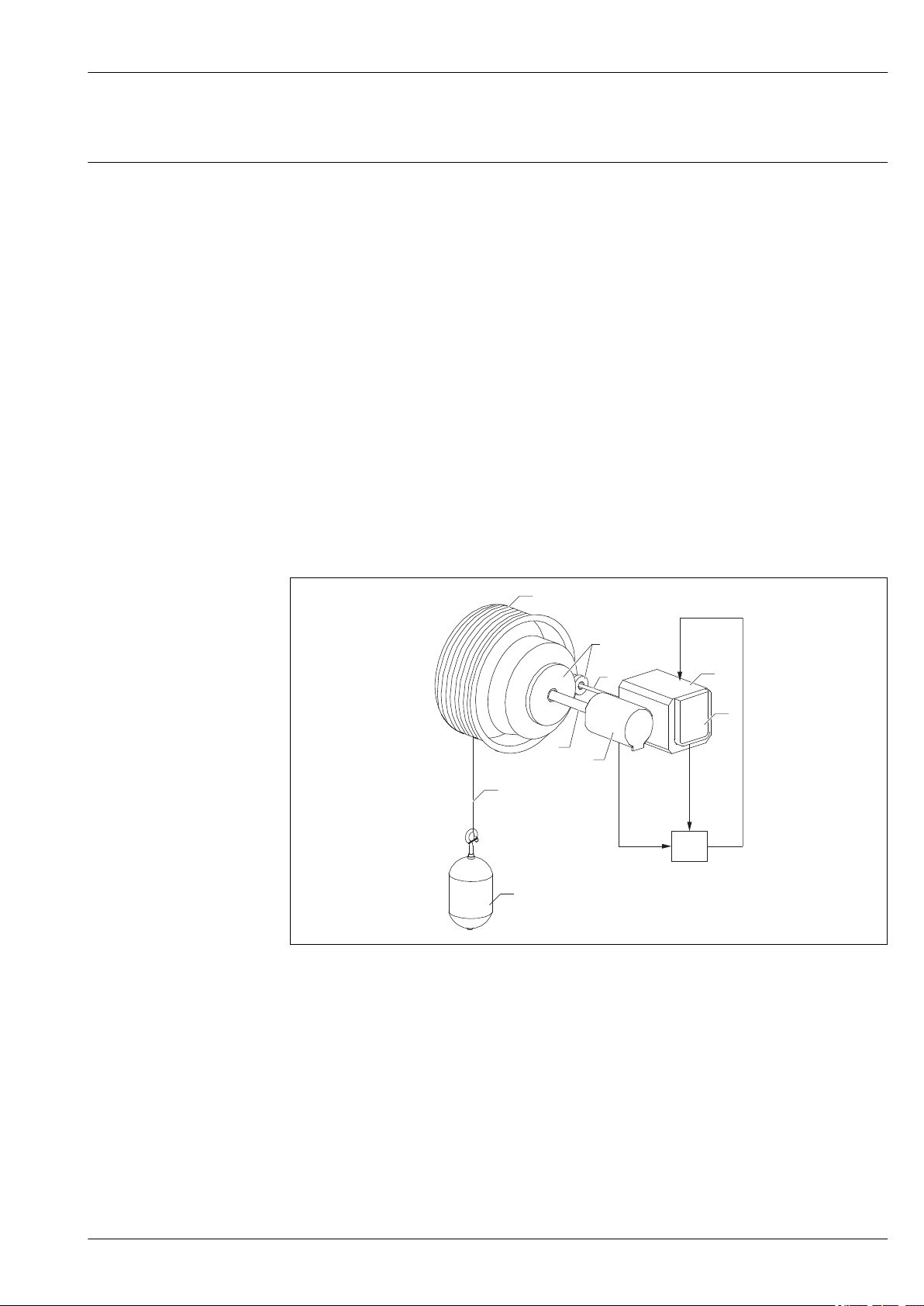
Measuring principle
NMS8x is an intelligent tank gauge for measuring liquid levels with high precision. The system is
based on the principle of gauging displacement.
A small displacer is accurately positioned in a liquid medium using a stepping motor. The displacer is
then suspended on a measuring wire which is wound onto a finely grooved wire drum. NMS8x
counts the rotations of the wire drum and to calculate the traveling distance of the wire and obtain
the liquid level change.
The drum is driven via coupling magnets that are completely separated by the drum housing. Outer
magnets are connected to the wire drum, with inner magnets connected to the drive motor. As the
inner magnets turn, their magnetic attraction causes the outer magnets to turn, as well, causing the
entire drum assembly to turn. The weight of the displacer on the wire creates torque on the outer
magnets generating change of magnetic flux. These changes generated in the drum assembly are
detected by a unique electromagnetic transducer on the inner magnets. The transducer transmits the
weigh signal to a CPU using a non contact principle (patented). The drive motor is actuated to keep
the weigh signal constant at set value defined by the operating command.
When the displacer is lowered and touches a liquid, the weight of the displacer is reduced by liquid
buoyancy force, which is measured by a temperature-compensated magnetic transducer. As a result,
the torque in the magnetic coupling changes, and this is measured by six hall sensors. A signal
indicating the weight of the displacer is sent to the motor control circuit. As the liquid levels rise and
fall, the displacer position is adjusted by the drive motor. The rotation of the wire drum is
continuously evaluated to determine the level value using a magnetic rotary encoder. In addition to
gauging the level, NMS8x can measure the interfaces between up to three liquid phases, and the
tank bottom, as well as spot and profile densities.
1 Operating principle
A Displacer position data
B Weight data
1 Encoder
2 Motor
3 Rotary transformer
4 Shafts
5 Gears
6 Wire drum
7 Measuring wire
8 Displacer
Endress+Hauser 5
A0026903
Page 6
Proservo NMS83
3
3
2
2
1
1
RTD
A
B
HART
Integration of tank sensors
In addition to measuring the level, interfaces, tank bottom, and density, the device can also be used
to integrate of tank sensors into tank inventory systems. All measured and calculated values can be
displayed on the built-in display. They can be transferred to an inventory control system via a field
communication protocol.
A0026902
2 Measuring system
A HART multidrop mode
B HART and analog mode
1 Spot temperature
2 Proservo NMS8x
3 Field protocol transmits data to an inventory control system
Typical values measured by the sensors are:
• Level
• Spot temperature
• Average temperature
• Water level
• Pressure
• Secondary level value (for critical applications)
Major applications
The number of measuring functions and output options, as well as the compact design, enables
NMS8x to be installed in a wide range of applications at minimal cost.
Alcohol, food, and beverage industries
In alcohol, food, and beverage processes and storages, there exist an extensive need to measure and
manage a wide variety of products. Remote tank gauging by NMS8x combined with an inventory
management system is an ideal way to measure and manage tank contents.
6 Endress+Hauser
Page 7
Proservo NMS83
3
4
1
2
Typical tank installation
A0026904
3 Typical tank installation 1
1 NMS8x
2 Measuring wire
3 Displacer
4 Stilling well
When installing NMS8x to a floating roof tank, be sure to use a stilling well to protect the
measuring wire. Otherwise the wire may break due to an external shock.
Application
NMS8x is primarily a highly accurate level measurement gauging instrument with the added ability
to measure density. The following level measurements are supported: liquid surface level and
interface level(s) between different liquids, as well as finding tank floor or datum plate. The
following density measurements are supported: single-point (spot measurements), as well as profile
measurements of all liquid(s) in a tank.
The choice of the most suitable displacer depends on the liquid conditions and measurement
functions. These can be classified as follows:
• Single measurement value only, e.g. level, interface, or density
• Multiple measurement application, e.g. level, interface, and density
Endress+Hauser 7
Page 8
Measurement terminology
2
1
3
7
6
5
4
Proservo NMS83
A0026906
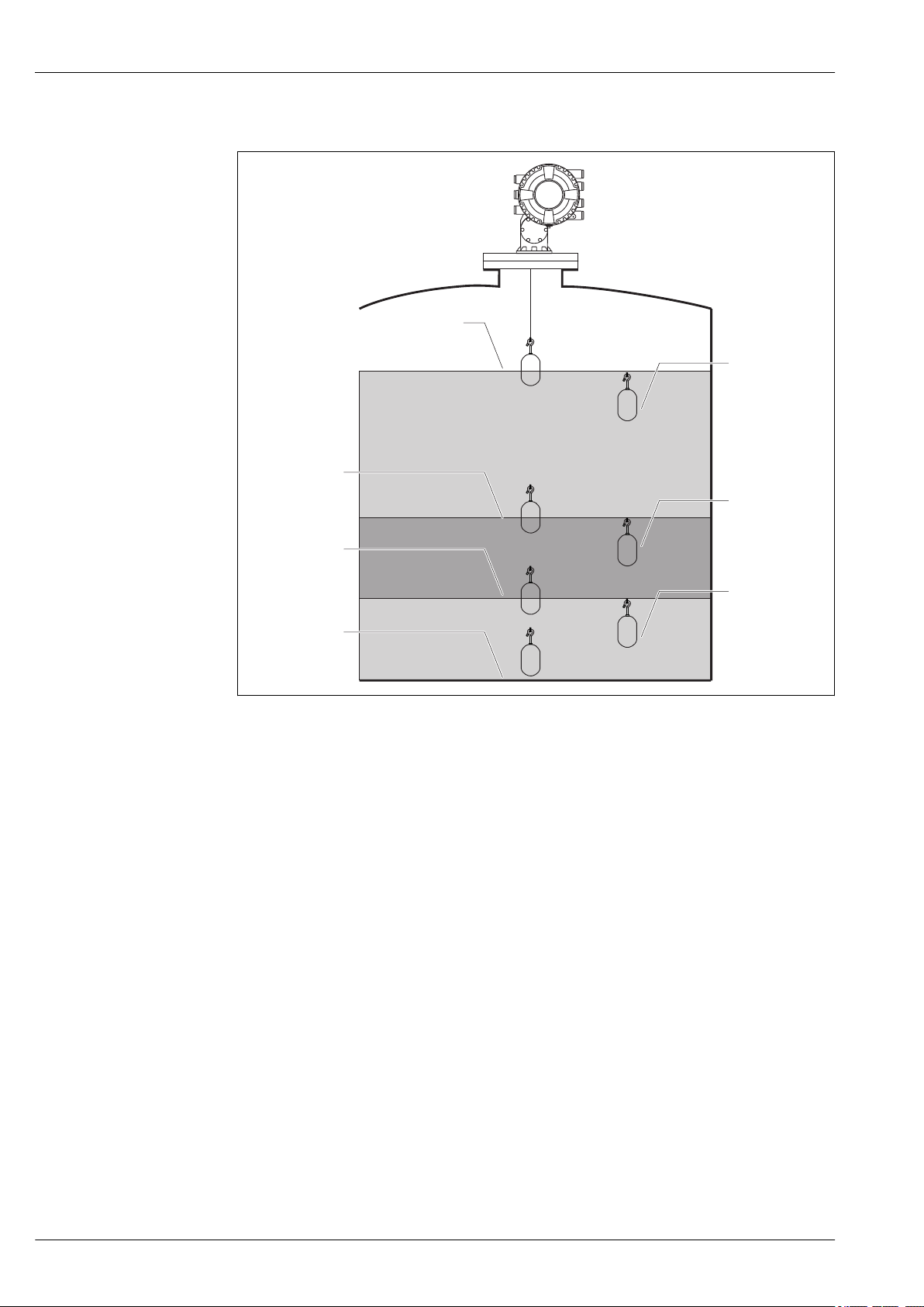
4 NMS8x with standard level, I/F x 2, Tank bottom and spot density x 3 measurement
1 Upper density
2 Middle density
3 Lower density
4 Tank bottom
5 Lower I/F
6 Upper I/F
7 Level
8 Endress+Hauser
Page 9
Proservo NMS83
BA C
4
3
1
2
5
6
A0026907
5 Density Profile measurement
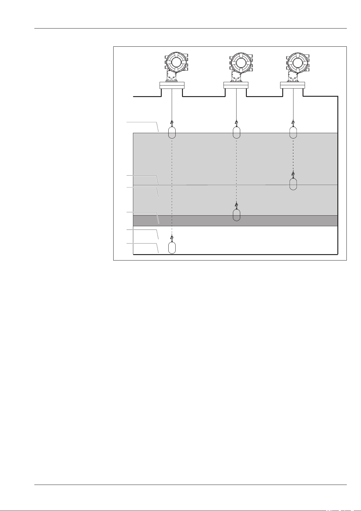
A Tank profile: density profiling throughout tank
B Interface profile: density profiling withing upper phase
C Manual profile: density profiling from a specific position to level
1 Level
2 Manual profile level
3 Upper phase (alcohol, liquid food, or beverage)
4 Middle phase (emulsion)
5 Lower phase (water)
6 Tank bottom
Endress+Hauser 9
Page 10
Proservo NMS83
Displacer selection guide
A wide variety of displacers are available to suit different application. Proper displacer selection
ensures optimal performance and longevity. The following guidelines will assist you in selecting the
most suitable displacer for your application.
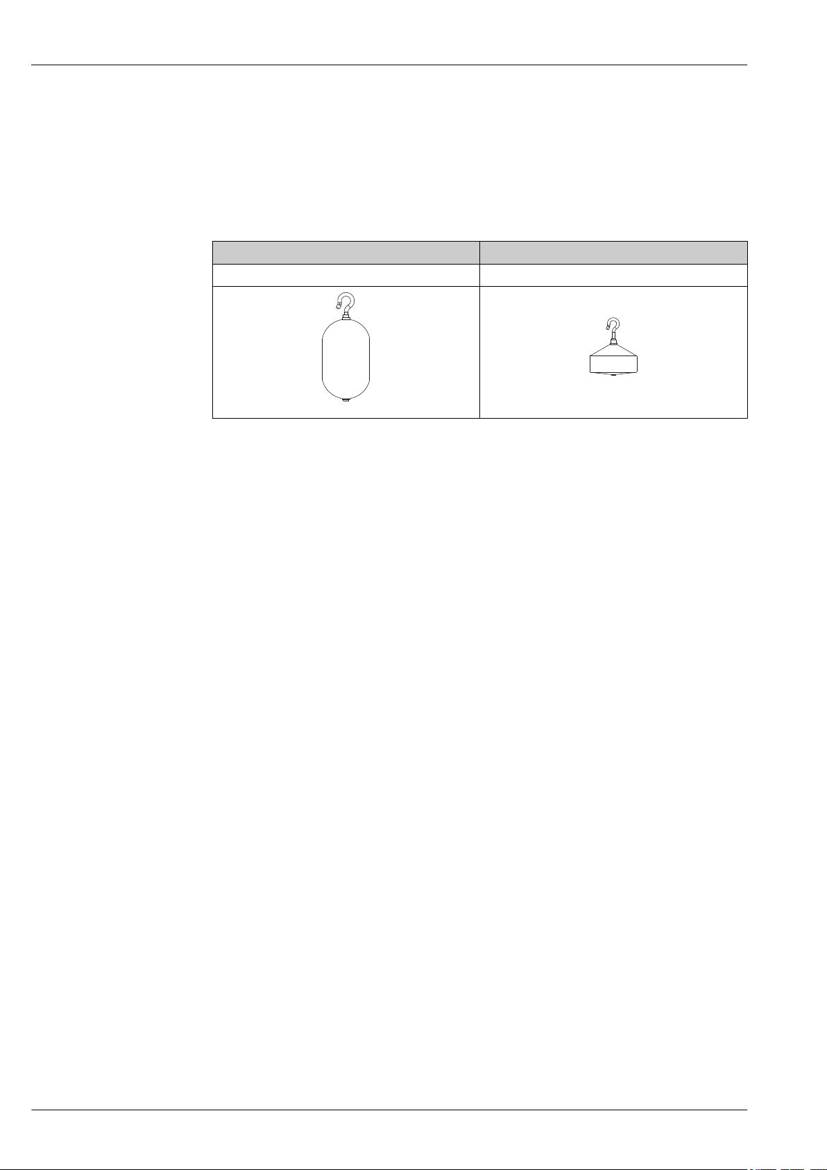
Displacer types
The following NMS8x displacers are available.
50 mm (1.97 in) 70 mm (2.76 in)
316L/PTFE 316L
A0032430
A0032429
10 Endress+Hauser
Page 11
Proservo NMS83
A
Ø50.8 (2)
a
45 (1.77)
85 (3.35)
116.6 (4.59)
2.5 (0.09)
B
Ø50 (1.97)
a
35 (1.38)
82.7 (3.26)
46.7 (1.84)
11.5
(0.45)
11.5
(0.45)
C
17 (0.67)
46.6 (1.83)
1 (0.03)
90 (3.54)
Ø70(2.76)
a
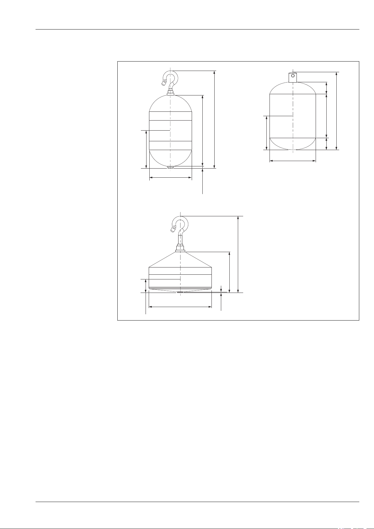
Displacer dimensions
A ⌀50 mm (1.97 in) 316L cylindrical displacer
B ⌀50 mm (1.97 in) PTFE cylindrical displacer
C ⌀70 mm (2.76 in) 316L conical displacer
a Immersion point
A0029581
Endress+Hauser 11
Page 12
Proservo NMS83
A
Ø50.8 (2)
a
45 (1.77)
85 (3.35)
116.6 (4.59)
2.5 (0.09)
B
Ø50 (1.97)
a
35 (1.38)
82.7 (3.26)
46.7 (1.84)
11.5
(0.45)
11.5
(0.45)
C
17 (0.67)
46.6 (1.83)
1 (0.03)
90 (3.54)
Ø70(2.76)
a
A ⌀50 mm (1.97 in) 316L cylindrical displacer
B ⌀50 mm (1.97 in) PTFE cylindrical displacer
C ⌀70 mm (2.76 in) 316L conical displacer
a Immersion point
Weight (g) 253 250 245
Volume (ml) 143 118 124
Balance volume (ml) 70.7 59 52.8
Item
⌀50 mm (1.97 in) 316L
cylindrical displacer
⌀50 mm (1.97 in) PTFE
cylindrical displacer
⌀70 mm (2.76 in) 316L
conical displacer
The weight, volume, and balance volume are individually determined by each displacer and also
might vary depending on the values stated above.
Recommended displacer by application
Application Product level Interface level Density
Viscous liquid 50 mm (1.97 in) PTFE Not Recommended Not Recommended
Not viscous liquid (e.g. alcohol) 50 mm (1.97 in) 316L 50 mm (1.97 in) 316L 50 mm (1.97 in) 316L
A0029581
12 Endress+Hauser
Page 13

Proservo NMS83
Product level
In general, larger diameter displacers have better accuracy under similar conditions.
Interface level(s)
Cylindrical-shaped displacers, with rounded top and bottom, reduce resistance while moving through
liquid(s). This provides smoother movement and faster interface measurements compared to flatfaced displacers, particularly in density profile measurements that span the full tank height.
In order to move a displacer down through liquids, the displacer density (weight divided by
volume) must be higher than the liquid density.
Tank bottom and datum plate level
70 mm (2.76 in) and 50 mm (1.97 in) displacers reduce resistance while moving through liquids.
This provides smoother movement and faster interface measurements.
Density
Since the density is the calculated result of two measurements, a displacer with higher volume will
usually yield the most accurate density measurement. In most cases we recommend our
50 mm (1.97 in) diameter displacer for density measurement.
For non-viscous applications (e.g. clear alcohol), the 70 mm (2.76 in) displacer also works very well.
Level and density
When an application calls for equal emphasis on measuring both level and density, the
50 mm (1.97 in) and the 70 mm (2.76 in) diameter displacers will give the best all-around
performance.
Custody transfer
The 50 mm (1.97 in) displacer or larger is the choice for requirements per NMi.
The 110 mm (4.33 in), conical 316L displacer is the choice for requirements per PTB.
Material compatibility
Displacers are available in three different standard materials. Material compatibility should be
confirmed to ensure safe operation and optimal NMS8x performance.
316L
Stainless steel is a highly versatile industrial material that provides good compatibility with a wide
range of alcohol, liquid food, and beverage applications.
Alloy C
This high-performance material is harder than 316L, and provides excellent resistance to many of
the harshest corrosive chemical applications.
PTFE
One of the most well-known and versatile polymer materials, this high-performance material has
one of the lowest friction coefficients. It provides excellent performance in viscous/sticky liquids, and
also has excellent chemical resistance to a wide range of corrosives.
Process connection size
The process connection defines the tank process entry, and may affect the displacer size. The
standard NMS8x process connections start at 3”/DN80 and fit most tank gauging applications.
Accordingly, most applications can be covered with one of the 50mm or 70mm displacer options.
Smaller diameter displacers are available when the process connection is smaller.
When the 110 mm (4.33 in) diameter custody transfer approval (PTB) displacer is selected, a
separate calibration and maintenance chamber is recommended between the NMS8x and tank
process connection.
Endress+Hauser 13
Page 14
Proservo NMS83
NXA820
NXA820
NXA820
NXA820
8
9
10
12
7
1
2
23 3 5 2 3
4 6
8
13
11
15
14
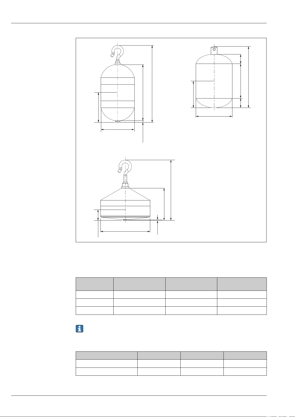
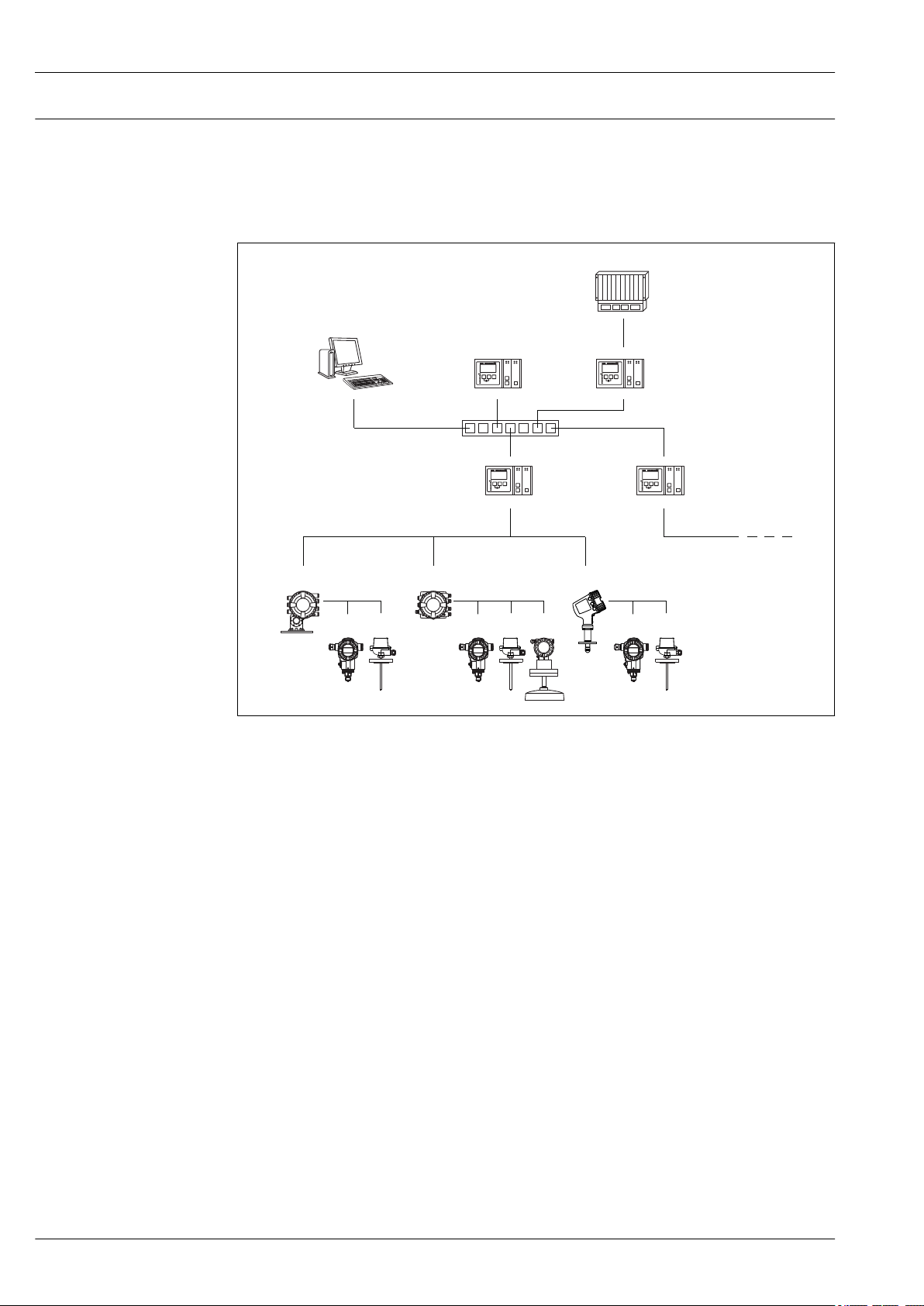
Measuring system
• From single tank level measurement to the largest process applications, Endress+Hauser tank
gauging devices are an integral part of tank farm management solutions. A wide variety of data
output protocols are available for seamless integration into many commonly used systems.
• A primary example is Tankvision from Endress+Hauser. Tankvision is a scalable system offering
local tank management for multiple loops via Modbus or V1 protocols. Accumulated data is
available to DCS and other plant management systems via a Host Link.
A0030168
6 Integration of tank gauging devices into an inventory management system (typical example)
1 Proservo NMS8x
2 Pressure transmitter (e.g. Cerabar)
3 Spot temperature (e.g. Modular thermometer)
4 Tankside Monitor NRF81
5 Micropilot S FMR5xx
6 Micropilot NMR8x
7 Field protocol (e.g. Modbus, V1)
8 Tankvision Tank Scanner NXA820
9 Ethernet
10 Ethernet switch
11 Internet Browser
12 Tankvision Data Concentrator NXA821
13 Tankvision Host Link NXA822
14 Modbus
15 DCS or PLC
14 Endress+Hauser
Page 15

Proservo NMS83
Input/output
Level measurement Measured variable
Proservo is primarily a highly accurate level measurement gauging instrument, with the added
ability to measure interfaces and densities. The following level measurements are supported: liquid
surface level and interface level(s) between different liquids, as well as finding tank bottom or datum
plate. The following density measurements are supported: single-point (called “spot”
measurements), as well as profile measurements of all liquid(s) in a tank.
Measuring range
• Level and interface: Max. 22 m (72 ft)(longer range is possible as special product)
• Density: 0.4000 to 2.000 g/cm
The level and interface measuring range depends on the measuring wire and material compatibility
to measured medium. Measuring wires are available in three different standard materials. Material
compatibility should be confirmed to ensure safe operation and optimal measuring performance.
3
Endress+Hauser 15
Page 16
HART Ex ia/IS active input
D
E
G
F
C
B
A
1
1
1
1
1 3
2
3
2
2 4
1
HR
CDI
WP
on
SIM
22334
4
112233445566778
8
POWER
i
E
1
1
2
CDI
D
C
1 2 3 4
1 2 3 4
Proservo NMS83
A0027364
7 HART Ex ia/IS active input
E1 HART +
E2 HART -
The device has a HART Ex ia/IS active input. Additional features are provided if the following
Endress+Hauser devices are connected:
Prothermo NMT
The measured level is transmitted to the Prothermo. Prothermo uses this level to calculate the
average temperature of the product.
Technical data
Transmitter power supply voltage 23.0 V - 380 Ω ⋅ I
load
Maximum load 500 Ω including signal line
Maximum current of all connected devices 24 mA
The HART Ex ia/IS active input is available by default. It needs not to be chosen explicitly when
ordering a device.
16 Endress+Hauser
Page 17
Proservo NMS83
E
G
F
1
1
1
1 3
2
2
2 4
HR
CDI
WP
on
SIM
POWER
i
D
C
B
A
1122334
4
112233445566778
8
D
E
F
C
B
A
1
1
1
1 3
2
2 4
1
HR
CDI
WP
on
SIM
22334
4
112233445566778
8
i
G
1
3
2
POWER
NMx8x - XX xx xxxxxx ...
040
NMx8x - xx XX xxxxxx ...
050
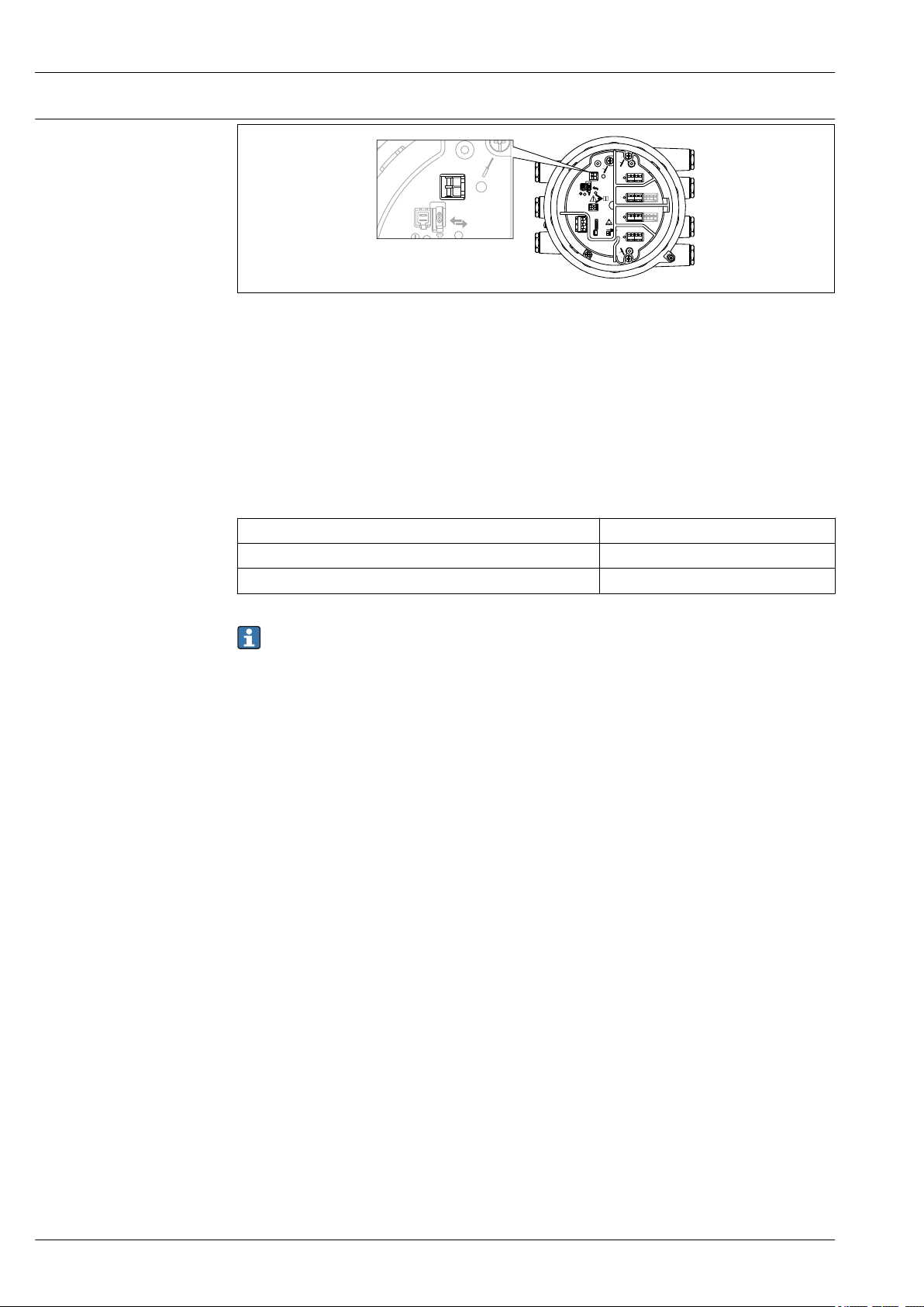
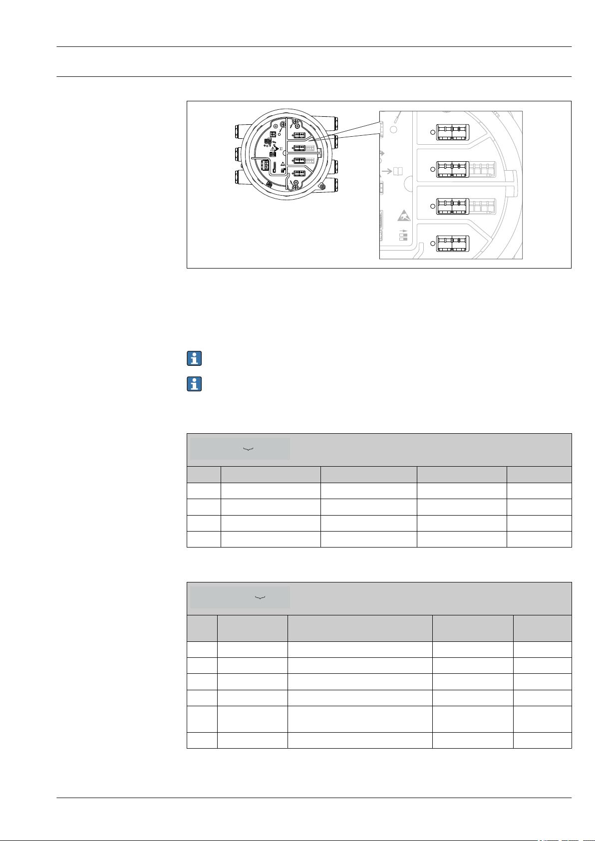
I/O modules Overview
8 Position of the I/O modules in the terminal compartment
The terminal compartment contains up to four I/O modules, depending on the order code.
• Modules with four terminals can be in any of these slots.
• Modules with eight terminals can be in slot B or C.
The exact assignment of the modules to the slots is dependent on the device version. For a
detailed description refer to the Operating Instructions of the device in question.
The following restrictions apply when selecting the modules:
• The device may contain a maximum of four I/O modules.
• A maximum of two I/O modules with 8 terminals is possible.
A0027363
Ordering feature 040: "Primary Output"
Option Number of I/O modules Type of I/O module Number of terminals Technical data
A1 1 Modbus RS485 4 → 18
B1 1 V1 4 → 19
E1 1 4-20mA HART Ex d/XP 8 → 20
H1 1 4-20mA HART Ex i/IS 8 → 20
Ordering feature 050: "Secondary IO Analogue"
Option Number of I/O
modules
A1 1 1 x "Ex d/XP 4-20mA HART + RTD input" 1 x 8 → 20
A2 2 2 x "Ex d/XP 4-20mA HART + RTD input" 2 x 8 → 20
B1 1 1 x "Ex i/IS 4-20mA HART+ RTD input" 1 x 8 → 20
B2 2 2 x "Ex i/IS 4-20mA HART+ RTD input" 2 x 8 → 20
C2 2 1 x "Ex i/IS 4-20mA HART + RTD input"
X0 0 none 0 -
Type of I/O module Number of terminals Technical data
2 x 8 → 20
1 x "Ex d/XP 4-20mA HART + RTD input"
Endress+Hauser 17
Page 18

Proservo NMS83
NMx8x - xx xx XXxxxx ...
060
Ordering feature 060: "Secondary IO Digital Exd"
Option Number of I/O modules Type of I/O module Number of terminals Technical data
A1 1 1 x "2x relay + 2x discrete I/O" 1 x 4 → 22
A2 2 2 x "2x relay + 2x discrete I/O" 2 x 4 → 22
A3 3 3 x "2x relay + 2x discrete I/O" 3 x 4 → 22
B1 1 1x "Modbus RS485" 1 x 4 → 18
B2 2 1x "Modbus RS485"
1 x "2x relay + 2x discrete I/O"
B3 3 1x "Modbus RS485"
2 x "2x relay + 2x discrete I/O"
X0 0 none 0 -
"Modbus RS485": Technical data
No. of units Maximum 15 instruments per loop
Baud rate Selectable:
• 600 bit/s
• 1 200 bit/s
• 2 400 bit/s
• 4 800 bit/s
• 9 600 bit/s
• 19 200 bit/s
Parity Selectable:
• Odd
• Even
• None
Cable Three-wire cable with screening. The screening must be connected inside the housing.
Termination resistors To be set as required in specific environments
Topology • Serial bus
• Tree structure
Transmission distance Maximum 1 200 m (3 900 ft) including limbs or branches;
branches under 3 m (9.8 ft) are negligible
Instrument address Each transmitter has an individual bus address configured in the software of the
transmitter.
Isolation Bus inputs are electrically isolated from the other electronics.
Error on alarm Error message classified according to NAMUR NE 107
2 x 4 → 18
→ 22
3 x 4 → 18
→ 22
18 Endress+Hauser
Page 19

Proservo NMS83
"V1": Technical data
No. of units Maximum 10 instruments per loop
Baud rate 3 300 bit/s
Parity Selectable:
• Odd
• Even
• None
Cable • Two-wire twisted pair; screening recommended
• Two-wire unscreened
Termination resistors Not required
Topology • Serial bus
• Tree structure
Transmission distance Maximum 6 000 m (19 700 ft)
Instrument address Each transmitter has an individual bus address configured in the software of the
transmitter.
Isolation Serial communication circuit isolated from other circuits
Error on alarm Error message classified according to NAMUR NE 107
Endress+Hauser 19
Page 20

Proservo NMS83
"4-20mA HART" I/O module (Ex d/XP or Ex i/IS): Technical data
General data
No. of units Max. 6 instruments per loop
Baud rate 1 200 bit/s
Cable Two-wire, twisted pair screened cable;
Core cross section: 0.2 to 2.5 mm2 (24 to 13 AWG)
Topology • Serial bus
• Tree structure
Transmission distance Maximum 1 200 m (3 900 ft)
Instrument address Each transmitter on a signal loop has an individual bus address. This is defined within
the transmitter software and / or auxiliary configuration environment such as host
system or Field Communicator 475.
Isolation Bus inputs are electrically isolated from the other electronics
Input data
Input operating modes • 4..20mA input (1 external device)
• HART master+4..20mA input (1 external device)
• HART master (up to 6 external devices)
Internal load (to ground) 400 Ω
Measuring range 0 to 26 mA
Accuracy ±15 µA (after linearization and calibration)
Connection of a Prothermo NMT The measured level is transmitted to the Prothermo. Prothermo uses this
level to calculate the average temperature of the product.
Connection of a RTD temperature
probe
2-, 3- or 4-wire connection
Output data
Output operating modes • 4..20mA output
• HART slave +4..20mA output
Output current 3 to 24 mA
Accuracy ±15 µA (after linearization and calibration)
Error on alarm HART error message classified according to NAMUR NE 107
20 Endress+Hauser
Page 21

Proservo NMS83
D
E
F
C
B
A
1
1
1
1 3
2
2 4
1
HR
CDI
WP
on
SIM
22334
4
112233445566778
8
i
G
1
3
2
POWER
-
+
!
E
G
F
1
1
1 3
2
2 4
HR
CDI
WP
on
SIM
i
D
C
B
A
1122334
4
112233445566778
8
G
1
3
2
POWER
D
E
F
C
B
A
1
1
1
1 3
2
2 4
1
HR
CDI
WP
on
SIM
22334
4
112233445566778
8
i
G
1
3
2
POWER
-
+
E
G
F
1
1
1 3
2
2 4
HR
CDI
WP
on
SIM
i
D
C
B
A
1122334
4
112233445566778
8
G
1
3
2
POWER
Data for passive usage (input or output)
9 Passive input or output: Use terminals 1 and 2
Minimum terminal voltage 10.4 V
Maximum terminal voltage 29 V
A0033030
1)
1)
1) Observing these values is mandatory in order to ensure correct measured value information.
Data for active usage (input or output)
10 Active input or output: Use terminals 2 and 3
Transmitter power supply voltage
(Ex d/XP)
Transmitter power supply voltage
(Ex i/IS)
Output load max. 500 Ω including signal line
18.5 V - 360 Ω ⋅ I
20.0 V - 360 Ω ⋅ I
load
load
1)
A0033031
Endress+Hauser 21
1) Observing this value is mandatory in order to ensure correct measured value information.
Page 22

Proservo NMS83
"Digital I/O module": Technical data
Output
Relay switching power for resistive load • 30 VDC @ 2 A
• 250 VDC @ 0.1 A
• 250 VAC @ 2 A
Relay type normally open;
can be set to "normally closed" by a software option
Input
Maximum pick-up voltage • 250 V
Minimum pick-up voltage • 25 V
• 250 V
• 5 V
DC
AC
DC
AC
Current consumption at maximum voltage • ≤ 1 mA (DC)
• ≤ 2 mA (AC)
1) In case of a power supply failure, the switching state is always "open", irrespectiv of the selected software
option.
1)
22 Endress+Hauser
Page 23

Proservo NMS83
D
E
G
F
C
B
A
1
1
1
1
1 3
2
2
2 4
1
HR
CDI
WP
on
SIM
22334
4
112233445566778
8
POWER
i
D
E
F
C
B
A
1
1
1
1 3
2
2 4
1
HR
CDI
WP
on
SIM
22334
4
112233445566778
8
i
G
1
3
2
POWER
G1 N
G3 L
AC 85...264 V
Terminal assignment
Power supply
A0032445
11 Terminal compartment (typical example) and ground terminals
Terminal area Module
Up to four I/O modules, depending on the order code
A/B/C/D
(slots for I/O
modules)
• Modules with four terminals can be in any of these slots.
• Modules with eight terminals can be in slot B or C.
The exact assignment of the modules to the slots is dependent on the device version.
For a detailed description refer to the Operating Instructions of the device in
question.
E HART Ex i/IS interface
• E1: H+
• E2: H-
F Remote display
• F1: VCC (connect to terminal 81 of the remote display)
• F2: Signal B (connect to terminal 84 of the remote display)
• F3: Signal A (connec t to terminal 83 of the remote display)
• F4: Gnd (connect to terminal 82 of the remote display)
Power consumption: 28.8 VA
Power supply: 85 to 264 V
G
• G1: N
1)
AC
• G2: not connected
• G3: L
Protective ground connection (M4 screw)
A0018339
1) Maximum power varies depending on the configuration of the modules. As the value of 28.8 VA shows
maximum apparent power, select the applicable cables accordingly. The actual consumed effective power is
12 w.
Sources for gauge commands
Gauge commands can be sent via various sources.
• Displays or CDI (e.g. FieldCare)
• Digital input (e.g. switch)
• Fieldbus (Modbus, V1, HART)
The last received gauge command via any sources will be executed as usual.
During calibration, gauge commands are not accepted from any sources.
Endress+Hauser 23
Page 24

X
X
X
X
X
X
X
X
X
mm
INST
LIFT
STOP
OFF
NXA820
1
2
3
1 Display operation
2 Digital input (e.g. switch)
3 Tankvision
Proservo NMS83
A0029575
Gauge command priorities
The priority of the gauge command for NMS8x is very simple. The last received gauge command via
any sources will be executed to take of the former gauge command. However the priority varies
depending on the devices. When replacing the device with the NMS8x, check the priorities shown
below.
NOTICE
Undesired gauge command will be executed.
If the setting is not changed, an undesired gauge command will be executed (e.g. Level command via
Fieldbus would overwrite Stop command for maintenance.).
If the system has been automatically or semi-automatically programmed for operation,
‣
maintenance or other purposes, the setting should be changed corresponding to use.
Proservo NMS8x
By display From digital input From Fieldbus
Command Priority Command Priority Command Priority
Level 1 Level 1 Level 1
Interface 1 Interface 1 Interface 1
Tank bottom 1 Tank bottom 1 Tank bottom 1
Spot density 1 Spot density 1 Spot density 1
Profile density 1 Profile density 1 Profile density 1
Up 1 Up 1 Up 1
Stop 1 Stop 1 Stop 1
Proservo NMS5/NMS7
By display From NRF560 From digital input From Fieldbus
Command Priority Command Priority Command Priority Command Priority
Level 4 Level 4 Level 4 Level 4
24 Endress+Hauser
Page 25

Proservo NMS83
By display From NRF560 From digital input From Fieldbus
Interface 2 Interface 3 Interface 1 Interface 4
Tank bottom 2 Tank bottom 3 N/A N/A Tank bottom 4
Spot density 2 Spot density 3 N/A N/A Spot density 4
Profile density 2 Profile density 3 N/A N/A Profile density 4
Up 2 Up 3 Up 1 Up 4
Stop 2 Stop 3 Stop 1 Stop 4
Servo level gauge TGM5
By display From NRF560 From DRM9700 From digital input From Fieldbus
Command Priority Command Priority Command Priority Command Priority Command Priority
Level 4 Level 4 Level 4 Level 4 Level 4
Interface 2 Interface 3 N/A N/A N/A N/A Interface 4
Tank
bottom
Spot density 2 Spot density 3 N/A N/A N/A N/A Spot density 4
Profile
density
Up 2 Up 3 Up 1 Up 1 Up 4
Stop 2 Stop 3 N/A N/A Stop 1 Stop 4
2 Tank
bottom
2 Profile
density
3 N/A N/A N/A N/A Tank
bottom
3 N/A N/A N/A N/A Profile
density
4
4
Supply voltage
Servo level gauge TGM4000
By display From DRM9700 From digital input From Fieldbus
Command Priority Command Priority Command Priority Command Priority
Level 4 Level 4 Level 4 Level 4
Interface 2 Interface 1 N/A N/A Interface 4
Tank bottom 2 N/A N/A N/A N/A Tank bottom 4
Spot density 2 N/A N/A N/A N/A Spot density 4
Profile density 2 N/A N/A N/A N/A Profile density 4
Up 2 Up 1 Up 1 Up 4
Stop 2 Stop N/A Stop 1 Stop 4
85 to 264 VAC, 50/60 Hz, 28.8 VA
1)
1) maximum value; actual value depending on modules installed. 28.8 VA includes the nominal power and the cabling specification has to meet this
value. On the other hand, the effective power consumption is 12 W.
Endress+Hauser 25
Page 26

Proservo NMS83
Cable entries
Ordering feature 090 "Electrical Connection"
A 7 x thread M20
B 7 x thread M25
C 7 x thread G1/2
D 7 x thread G3/4
E 7 x thread NPT1/2
F 7 x thread NPT3/4
1) Position 13 of the order code, e.g. NMx8x-xxxxxxxxxxxxA...
For the following devices with TIIS Ex d approval, cable glands are attached to the device (see
position 1 and 2 of the order code). These cable glands must be used.
Proservo NMS83-TC...
Cable specification Terminals
Terminal Wire cross section
Signal and power supply
• Spring terminals (NMx8x-xx1...)
• Screw terminals (NMx8x-xx2...)
Ground terminal in the terminal compartment max. 2.5 mm2 (13 AWG)
Ground terminal at the housing max. 4 mm2 (11 AWG)
1)
Cable entries (with blind plugs)
0.2 to 2.5 mm2 (24 to 13 AWG)
Overvoltage protection
Power supply line
Standard device cable is sufficient for the power line.
HART communication line
• Standard device cable is sufficient if only the analog signal is used.
• Shielded cable is recommended if using the HART protocol. Observe the grounding concept of the
plant.
Modbus communication line
• Observe the cable conditions from the TIA-485-A, Telecommunications Industry Association.
• Additional conditions: Use shielded cable.
V1 communication line
• Two wire (twisted pair) screened or un-screened cable
• Resistance in one cable: ≤ 120 Ω
• Capacitance between lines: ≤ 0.3 µF
On the communication and power lines; according to IEC 60060-1 /DIN 60079-14:
10 kA, 8/20 μs, 10 pulses according to IEC 60060-1 / DIN 60079-14
26 Endress+Hauser
Page 27

Proservo NMS83
Performance characteristics
Reference operating conditions
Measured value resolution
Maximum measured error
According to OIML R85
Level and interface ≤ 0.1 mm (0.004 in)
Density
Level ±0.4 mm (±0.016 in) Reference condition
Interface ±2 mm (±0.08 in) Reference condition
Tank bottom ±2 mm (±0.08 in) Reference condition
Density ±0.003 g/cm
≤ 0.001 g/cm
3
3
Accuracy of NMi approved calibration rig at Endress
+Hauser Yamanashi according to the combination of
the order code is as per the table below.
• Standard displacer 70 mm (2.76 in)
• Density difference 0.2 g/cm3 or more (min.
detectable density difference for interface
measurement is 0.1 g/cm
• Max. performance selected in feat.150
• Standard displacer 70 mm (2.76 in)
• Flat datum plate or flat tank bottom
• Max. performance selected in feat.150
Reference condition
• Standard displacer 50 mm (1.97 in) or
70 mm (2.76 in)
• On-site density calibration (offset)
• Max. performance selected in feat.150
3
The following values are valid for a level measurement distance up to 22 m (73.33 ft)
Displacer (ordering feature 120)
Ordering
feature 150
ICR Standard version, w/o calibration certificate ±1 mm (±0.04 in) ±1 mm (±0.04 in)
ICW Standard version, 3-point calibration
ICX Standard version, 5-point calibration
NTA Maximum performance, NMi type approval
NTC Custody transfer type approval acc. NMi
PTA Maximum performance, PTB type approval
PTC Custody transfer type approval per PTB,
Weight and measure approval
certificate
certificate
acc. OIML R85, API 3.1B, ISO 4622, factory
calibration certificate
OIML R85, API 3.1B, ISO4622, factory
calibration certificate
factory calibration certificate
factory calibration certificate
1AC, 2AC, 3AC, 4AC,
5AC
⌀50 mm (1.97 in) ⌀70 mm (2.76 in)
Accuracy
±1 mm (±0.04 in) ±1 mm (±0.04 in)
±1 mm (±0.04 in) ±1 mm (±0.04 in)
±0.6 mm (±0.024 in)
±1 mm (±0.04 in) ±1 mm (±0.04 in)
±0.6 mm (±0.024 in)
±1 mm (±0.04 in) ±1 mm (±0.04 in)
1BE, 4AE
±0.4 mm
(±0.016 in)
±0.4 mm
(±0.016 in)
Hysteresis
Within the specified accuracy (+/- 1 mm (0.039 in)) according to OIML R85 (2008)
It can be reduced by non hysteresis measurement mode.
Endress+Hauser 27
Page 28

Proservo NMS83
Repeatability
Linearity
Long-term drift
Influence of ambient temperature
Influence of medium temperature
Influence of medium pressure
Effect of gas phase
0.1 mm (0.004 in)
Within maximum measured error
Within the specified error of measurement
Within the specified accuracy according to OIML R85 (2008)
None (Displacer principle is not influenced by medium temperature.)
No influence of medium pressure to the measuring principle.
No effect of gas phase to the measuring principle.
28 Endress+Hauser
Page 29

Proservo NMS83
Installation
Requirements Type of tanks
Depending on the type of tank and application, different installation procedures are recommended
for NMS8x.
Type of tanks Without guide system With stilling well With guide wires
Fixed roof tank
Tank with agitator or heavy
turbulence
A0032437 A0032438 A0032439
A0032440 A0032441
• A stilling well is required in a floating roof tank and a covered floating roof tank.
• Guide wires cannot be installed in a floating roof tank. When the measuring wire is exposed
to free space, it may break due to an external shock.
• Installing guide wires is not allowed in pressurized tanks because the wires would prevent
closing the valve for replacing the wire, wire drum, or displacer. NMS8x installation position
is important for applications without the guide wire system in order to prevent the measuring
wire from being broken (refer to Operating Instructions for details ).
Endress+Hauser 29
Page 30

Proservo NMS83
L
1
L
2
L
1
L
2
A
B
L
3
L
3
D
2
D
1
d
r
D
1
d
D
2
p(L )x
Mounting with a stilling well
The stilling well diameter that is required to protect the measuring wire without disturbing its
operation varies depending on the tank height. The stilling well could either be of constant diameter,
or narrower at its upper part and wider at its lower part. The following figure shows two examples of
the latter case, namely a concentric stilling well and an asymmetric stilling well.
A0029574
12 Mounting with concentric stilling well
A Front view
B Side view
L1Length from the center of the calibration window to the upper part of the stilling well
L2Length from the center of the calibration window to the bottom of the stilling well
L3Length from the center of the calibration window to the bottom of the flange
D1Diameter of upper part of stilling well
D2Diameter of stilling well
d Diameter of displacer
p
Longitudinal wire position from the center of the flange
(Lx)
r Radial direction offset
30 Endress+Hauser
Page 31

Proservo NMS83
L
1
L
2
L
1
L
2
A
B
L
3
L
3
D
2
D
1
d
r
D
1
d
D
2
p (L )x
A0026909
13 Mounting with asymmetric stilling well
A Front view
B Side view
L1Length from the center of the calibration window to the upper part of the stilling well
L2Length from the center of the calibration window to the bottom of the stilling well
L3Length from the center of the calibration window to the bottom of the flange
D1Diameter of upper part of stilling well
D2Diameter of stilling well
d Diameter of displacer
p
Longitudinal wire position from the center of the flange
(Lx)
r Radial direction offset
• L3: length from center of the calibration window to the bottom of the flange
(77 mm (3.03 in) + flange thickness).
For JIS 10K 150A RF, the flange thickness is 22 mm (0.87 in).
• When using an asymmetric stilling well, take into account the lateral shift of the displacer
and follow the NMS8x mounting direction as shown in the figure.
• To calculate the required stilling well diameters, the formula below should be used. The
following tables contain the necessary parameters in order to calculate the dimensions of the
stilling well. Be sure to have appropriate dimensions of the stilling well according to each
dimension in the table.
• The radial direction offset (r) is required for only the 47 m (154.20 ft) and 55 m (180.45 ft)
wire drum. For all other drums, the offset is 0 mm/in.
Endress+Hauser 31
Page 32

Proservo NMS83
Feature: 110 Description
(Measuring range; Wire;
Diameter)
G1
H1
Feature: 120 Description
1AA 316L; 30 mm (1.18 in) cylindrical 30 mm (1.18 in)
1AC 316L; 50 mm (1.97 in) cylindrical 50 mm (1.97 in)
1BE 316L; 70 mm (2.76 in) conical 70 mm (2.76 in)
1BJ 316L;110 mm (4.33 in) conical 110 mm (4.33 in)
2AA PTFE; 30 mm (1.18 in) cylindrical 30 mm (1.18 in)
2AC PTFE; 50 mm (1.97 in) cylindrical 50 mm (1.97 in)
3AC AlloyC276; 50 mm (1.97 in)
4AC 316L polished; 50 mm (1.97 in)
4AE 316L polished; 70 mm (2.76 in)
5AC PTFE; 50 mm (1.97 in) cylindrical,
47 m (154.20 ft); 316L;
0.15 mm (0.00591 in)
55 m (180.45 ft); 316L
0.15 mm (0.00591 in)
(Displacer material; Type)
cylindrical
cylindrical
conical
hygienic white
NMS80 NMS81 NMS83 r
6 mm (0.24 in)
6 mm (0.24 in)
NMS80 NMS81 NMS83 d
50 mm (1.97 in)
50 mm (1.97 in)
70 mm (2.76 in)
50 mm (1.97 in)
Parameter Description
d Diameter of displacer
p(Lx) Longitudinal wire position from the center of the flange
The value can be determined by using following graph.
r Radial direction offset
s Safety factor recommended: 5 mm (0.197 in)
The following graph shows the lateral shift of the displacer depending on the measured distance for
the different wire drums.
32 Endress+Hauser
Page 33

Proservo NMS83
L , L (mm) ( )
1 2
in
p (Lx) (mm) ( )in
-1.4 -1.3 -1.2 -1.1 -1.0 -0.9 -0.8 -0.7 -0.6 -0.5 -0.4 -0.3 -0.2 -0.1 0.0 0.1 0.2 0.3
0
100
200
300
400
500
600
700
800
900
1000
1100
1200
1300
1400
1500
1600
1700
1800
1900
2000
2100
2200
0
2000
4000
6000
8000
10000
12000
14000
16000
18000
20000
22000
24000
26000
28000
30000
32000
34000
36000
38000
40000
42000
44000
46000
48000
50000
52000
54000
56000
-36 -32 -28 -24 -20 -16 -12 -8 -4 0 4 8
a
d
e
c
b
f
A0027997
14 Lateral shift of displacer according to measurement range
a 16 m (A3) (NMS80/NMS81/NMS83)
b 22 m (C2) (NMS80/NMS81/NMS83)
c 28 m (D1) (NMS80/NMS81)
d 36 m (F1) (NMS80/NMS81)
e 47 m (G1) (NMS81)
f 55 m(H1) (NMS81)
Upper diameter of stilling well
The dimension of D1 has to be the largest value of the dimensions D1a, D1b , D1c, and D1d according to
the following formula.
Endress+Hauser 33
D1 Dimension
(Example)
>68.1 mm
(2.68 in)
D
Dimension
1x
Example Parameter
68.1 mm
(2.68 in)
65.6 mm
(2.58 in)
Description Formula
D
1a
D1 dimension when the
= 2 x ( |p (0)|+ d/2 + s)
displacer is at the center of the
calibration window
D
1b
D1 dimension when the
= 2 x (|p (L1)|+ d/2 + s)
displacer is at the upper part of
the stilling well
Page 34

Proservo NMS83
D1 Dimension
(Example)
D
Dimension
1x
Example Parameter
50.9 mm
(2.00 in)
D
1c
D
1d
Description Formula
D1 dimension when the
displacer is at the bottom of the
stilling well
D1 dimension when the radial
direction offset is considered.
This calculation is used only
with the 47 m (154.20 ft) wire
drum (G1 in Feature110) and
55 m (180.45 ft) (H1 in feature
110)
= 2 x ( |p (L2)|+ s)
= 2 x (d/2 + r + s)
Example: L1 = 1 000 mm, L2 = 20 000 mm, d = 50 mm, s = 5.0, 28 m drum
Lower diameter of stilling well
The dimension of D2 has to be the larger value of the dimensions D1 and D2b .
See the table below.
Concentric pipe
D2 Dimension
(Example)
>100.9 mm
(3.97 in)
D2x Dimension
Example Parameter
68.1 mm
(2.68 in)
100.9 mm
(3.97 in)
D
1
D
2b
Description Formula
Calculated D1 value
D2 dimension when the displacer is
in L2 length
= 2 x (|p (L2)| + d/2 + s)
Example: L2 = 20 000 mm, d = 50 mm, s = 5.0, 28 m drum
Asymmetric pipe
D2 Dimension
(Example)
>84.5 mm
(3.33 in)
D2x Dimension
Example Parameter
68.1 mm
(2.68 in)
84.5 mm
(3.33 in)
D
1
D
2b
Description Formula
Calculated D1 value
D2 dimension that the displacer can
pass through (nth groove)
= |p (L2)| + d/2 + s + D1/2
Example: L2 = 20 000 mm, d = 50 mm, s = 5.0, 28 m drum
Recommendations for NMS8x mounting with a stilling well
Follow the recommendations for mounting NMS8x with a stilling well.
• Keep the pipe connection welds smooth.
• When drilling holes into the pipe, keep the interior surface of the holes clear of metal chips
and burrs.
• Keep the pipe as vertical as possible. Check using a plumb bob.
• Install the asymmetric pipe under the valve and align the centers of the NMS8x and the
valve.
• Set the center of the lower part of the asymmetric pipe in the direction of the lateral motion.
• Observe the recommendations as per API MPMS chapter 3.1B.
• Confirm grounding between NMS8x and the tank nozzle.
34 Endress+Hauser
Page 35

Proservo NMS83
Environment
Ambient temperature range
Classification of environmental conditions according to DIN EN 60721-3-4
Storage temperature
Humidity
Degree of protection
Electromagnetic compatibility (EMC)
Device –40 to +60 °C (–40 to +140 °F)
Display module –20 to +70 °C (–4 to +158 °F)
The readability of the display may be impaired at temperatures outside this
temperature range.
4K5, 4K6, 4B1, 4M7, 4Z2, 4Z3, 4Z8
–50 to +80 °C (–58 to +176 °F)
≤ 95 %
• IP68/66 according to DIN EN 60529
• Type 6P/4x according to NEMA 250
• Transient emissions according to DIN EN 61326, class B
• Interference resistance according to DIN EN 61326, Appendix A (Industry use) and NAMUR
recommendation NE21
Endress+Hauser 35
Page 36

Process
1
2
3
4
5
6
Proservo NMS83
Process temperature range
–200 to +200 °C (–328 to 392 °F)
If the specification of the tank application exceeds the range above, a special displacer can be
ordered.
Process sealing
A1 HNBR –30 to 150 °C (–22 to 302 °F)
B1 FKM, GLT –40 to 150 °C (–40 to 302 °F)
C1 CR Chloropren –30 to 80 °C (–22 to 176 °F)
D1 PTFE (Wire drum FKM) –100 to 150 °C (–148 to 302 °F)
E1 VMQ silicone –40 to 200 °C (–40 to 392 °F)
A temperature difference exists between the liquid in the tank and the NMS8x on the tank
nozzle due to the distance from each other. Also, the process sealing temperature of NMS8x
does not show the temperature for the liquid temperature. The process sealing temperature
shows the temperature of the gas that reaches inside the housing of the NMS8x. In most cases,
the gas temperature is the same as the ambient temperature. If there are any temperature
differences between the process sealing and the gas, install a pipe or chamber between the
NMS8x and the tank nozzle to adjust the temeparature or cover the tank with a heat insulting
material to control the temperature.
15 Process sealing
1 Chamber or pipe for adjusting temperature
2 Heat insulting material
3 Measuring wire
4 Displacer
5 Tank wall
6 High or low temperature liquid
Process pressure range
Medium density
Housing type Process pressure range
Stainless steel 0 to 6 bar(600 Kpa/0 to 87 psi)
0.430 to 2.000 g/cm3 (27 to 125 lb/ft3)
36 Endress+Hauser
A0028848
Page 37

Proservo NMS83
Medium density difference for interface measurement
Viscosity
0.1 g/cm3 (6.24 lb/ft3)
0 to 5 000 mPa s
Endress+Hauser 37
Page 38

Custody transfer approval
Proservo NMS83
Ordering feature 150
"Accuracy, Weight +
Measure Approval"
ICR Standard version (±1 mm), without calibration certificate
ICW Standard version (±1 mm), 3-point calibration certificate
ICX Standard version (±1 mm), 5-point calibration certificate
LTA Maximum performance (±0.4 mm), type approval according to LNE, OIML R85, API
LTC Custody transfer (±1 mm) type approval according to NMi, OIML R85, API 3.1B,
NTA Maximum performance (±0.4 mm), type approval according to NMi, OIML R85, API
NTC Custody transfer (±1 mm) type approval according to NMi, OIML R85, API 3.1B,
PTA Maximum performance (±0.4 mm), PTB type approval, factory calibration certificate
PTC Custody transfer (±1 mm) type approval per PTB, factory calibration certificate
1) Position 25 to 27 in the order code (e.g. NMS8x-xxxxxxxxxxxxxxxxxxxxxxxxICR...)
Accuracy properties
1)
3.1B, ISO4622, factory calibration certificate
ISO4622, factory calibration certificate
3.1B, ISO4622, factory calibration certificate
ISO4622, factory calibration certificate
• Depending on the displacer (ordering feature 120) some of these versions will not be
available.
• Proservo NMS8x that are certified for Custody Transfer applications are calibrated on a
certified production rig. The production rig reference standard is a laser tracker with an
absolute accuracy of ±0.010 mm and a resolution of 0.0002 mm. Calibration is performed at
10 equally-spaced measuring points over the full measuring range (up to 40 m (131 ft)).
Additionally, hysteresis is checked at three points.
• The Maximum Permissible Error (MPE) is 0.4 mm (0.016 in) for maximum performance
models, and ±1 mm (±0.04 in) for custody transfer models. The resultant factory calibration
certificate is included in the scope of delivery along with the respective type approval
certificate.
38 Endress+Hauser
Page 39

Proservo NMS83
414 (16.8)
314 (12.36)
218 (8.58)
73 (2.87)
22 (0.87)
314 (12.36)
313.5 (12.34)
227.5 (8.96)
48 (1.89)
135 (5.31)
55 (2.17)
100.3 (3.95)
213.5 (8.41)
99 (3.9)
218 (8.58)
213.5 (8.41)
Dimensions
Mechanical construction
Weight
The thickness of the flange (22 mm (0.87 in)) shows the specification of the 10K 150A RF
aluminium flange JIS B2220.
• Approx. 30 kg (66.1 lb) with NPS 3" Cl.150, DN80PN10/16, 10K80A, 80A150lbs flange
• Approx. 37 kg (81.6 lb) with NPS 6" Cl.150, 10K150A flange
The weights vary depending on the selected options.
The weights described above show the products in order option 070 AC (Transmitter Alu,
coated, process 316/316L). The weight of products in order option BC (Transmitter + process
316/316L) is approximately 7.8 kg (17.2 lb) heavier than that of AC.
A0026911
Endress+Hauser 39
Page 40

Materials Material of housing
1
2
3
Feature Option Housing descriptions
070 AC Transmitter Alu, coated, process 316/316L
Materials of measuring wire
Feature Option Wire descriptions
110 A3 16 m (53.33 ft); PFA >316L; 0.4 mm (0.016 in)
110 C1 22 m (73.33 ft); 316, 0.2 mm (0.008 in)
Material of process connection (flange)
Feature Option Descriptions of process connection (flange)
140 AFJ NPS 3" Cl.150 RF, 316/316L flange ASME B16.5
140 AHJ NPS 6" Cl.150 RF, 316/316L flange ASME B16.5
140 GSJ DN80 PN10/16 B1, 316L flange EN1092-1
140 PFJ 10K 80A RF, 316L flange JIS B2220
140 PHJ 10K 150A RF, 316L flange JIS B2220
140 P5J 10K 80A FF,316L flange JIS B2220
140 P6J 10K 100A FF, 316L flange JIS B2220
140 QFJ 80A 150lbs RF, 316L flange JPI 7S-15
Proservo NMS83
A0029114
1 Housing
2 Flange
3 Measuring wire
40 Endress+Hauser
Page 41

Proservo NMS83
1
E
Operability
Operating concept
Operating options
Operator-oriented menu structure for user-specific tasks
• Commissioning
• Operation
• Diagnostics
• Expert level
Operating languages
• English
• German
• Japanese
Feature 500 of the product structure determines which of these languages is preset on delivery.
Quick and safe commissioning
• Guided menus ("Make-it-run" wizards) for applications
• Menu guidance with brief explanations of the individual parameter functions
Reliable operation
Standardized operation at the device and in the operating tools
Efficient diagnostics increase measurement reliability
• Remedy information is integrated in plain text
• Diverse simulation options
• Local display; operation via the local display is possible without opening the device.
• Tank Gauging system
• Plant Asset Management tool (e.g. FieldCare); connected via
– HART
– Service port (CDI)
Local operation
16 NMS83 Display
1 Display
Display elements
• 4-line display
• White background lighting; switches to red in event of device errors
• Format for displaying measured variables and status variables can be individually configured
• Permitted ambient temperature for the display: –20 to +70 °C (–4 to +158 °F)
The readability of the display may be impaired at temperatures outside the temperature range.
Operating elements
• External operation via touch control; 3 optical keys:
, ,
• Operating elements also accessible in various hazardous areas
A0028870
Endress+Hauser 41
Page 42

Remote operation
NXA820
5
6
4
1 2 3
7
2
3
CDI
1
Proservo NMS83
A0025621
17 Remote operation of Tank Gauging devices
1 Proservo NMS8x
2 Tankside Monitor NRF81
3 Micropilot NMR8x
4 Field protocol (e.g. Modbus, V1)
5 Tankvision Tank Scanner NXA820
6 Ethernet
7 Computer with operating tool (e.g. FieldCare)
Operation via service interface
A0028871
18 Operation via service interface
1 Service interface (CDI = Endress+Hauser Common Data Interface)
2 Commubox FXA291
3 Computer with "FieldCare" operating tool and "CDI Communication FXA291" COM DTM
42 Endress+Hauser
Page 43

Proservo NMS83
Certificates and approvals
Currently available certificates and approvals can be called up via the product configurator.
CE mark
RCM-Tick marking
Ex approval
Single seal according to ANSI/ISA 12.27.01
The measuring system meets the legal requirements of the applicable EC guidelines. These are listed
in the corresponding EC Declaration of Conformity together with the standards applied.
Endress+Hauser confirms successful testing of the device by affixing to it the CE mark.
The supplied product or measuring system meets the ACMA (Australian Communications and Media
Authority) requirements for network integrity, interoperability, performance characteristics as well
as health and safety regulations. Here, especially the regulatory arrangements for electromagnetic
compatibility are met. The products are labelled with the RCM- Tick marking on the name plate.
A0029561
The devices are certified for use in hazardous areas and the relevant safety instructions are provided
in the separate "Safety Instructions" (XA) document. Reference is made to this document on the
nameplate.
The separate documentation "Safety Instructions" (XA) containing all the relevant explosion
protection data is available from your Endress+Hauser Sales Center.
The devices have been designed according to ANSI/ISA 12.27.01 as single seal devices, allowing the
user to waive the use and save the cost of installing external secondary process seals in the conduit
as required by the process sealing sections of ANSI/NFPA 70 (NEC) and CSA 22.1 (CEC) These
instruments comply with the North-American installation practice and provide a very safe and costsaving installation for pressurized applications with hazardous fluids.
Further information can be found in the Safety Instructions (XA) of the relevant devices.
Functional Safety (SIL)
WHG
Weight & Measure approval
Non-ionizing radiation protection
Pressure Equipment Directive 2014/68/EU (DGRL / PED)
Use for level monitoring (MIN, MAX, range) up to SIL 2 according to IEC 61508:2010.
For details refer to the "Functional Safety Manual":
SD01920G (NMS80, NMS81, NMS83)
in preparation
• OIML R85 (2008)
• NMi
• PTB
• PAC
• WELMEC
• GOST (in preparation)
The device has a sealable locking switch according to the Weight & Measure requirements. This
switch locks all software parameters related to the measurement. The switching status is
indicated on the display and via the communication protocol.
According to guideline 2004/40/EG-ICNIRP Guidelines EN50371
Pressure equipment can be classified as pressurized equipment in accordance with Pressure
Equipment Directive 2014/68/EU, if the volume V > 1 l (0.264 gal). If the product of max. allowable
pressure PS and the pressurized volume V of the sensor, i.e. PS*V ≤ 25 bar l (95.7 psi gal), the
pressure equipment is subject to the Pressure Equipment Directive (c.f. Pressure Equipment Directive
2014/68/EU, Article 4, point 3). The Pressure Equipment Directive only requires that the pressure
equipment shall be designed and manufactured in accordance with the “sound engineering practice
of a Member State”.
Endress+Hauser 43
Page 44

Proservo NMS83
Reasons:
• Pressure Equipment Directive (PED) 2014/68/EU Article 4, point 3
• Pressure equipment directive 2014/68/EU, Commission's Working Group “Pressure”, Guideline
A-08
Note:
A partial examination shall be performed for pressure instruments that are part of safety equipment
for the protection of a pipe or vessel from exceeding allowable limits (equipment with safety
function in accordance with Pressure Equipment Directive 2014/68/EU, Article 2, point 4).
Test, certificate
Other standards and guidelines
Ordering feature 580 "Test,
Certificate"
JA 3.1 Material certificate, wetted metallic parts, EN10204-3.1 inspection
JB Conformity to NACE MR0175, wetted metallic parts
JE Conformity to NACE MR0103, wetted metallic parts
KE Pressure test, internal procedure, inspection certificate
Designation
certificate
Industry standards
• Directive 2002/95/EC: "Restriction of Hazardous Substances Directive" (RoHS)
• Directive 2004/22/EC: "Measuring Instruments Directive" (MID)
• IEC61508: "Functional Safety of Electrical/Electronic/Programmable Electronic Safety-related
Systems" (SIL)
• NACE MR 0175, NACE MR 0103: "Sulfide stress cracking resistant metallic materials for oilfield
equipment"
• API Recommended Practice 2350: "Overfill Protection for Storage Tanks in Petroleum Facilities"
• API MPMS: "Manual of Petroleum Measurement Standards"
• EN 1127: "Explosive atmospehres - Explosion prevention and protection"
• IEC 60079: "Equipment protection"
• EN 1092: "Flanges and their joints"
• EN 13463: "Non-electrical equipment for use in potentially explosive atmospheres"
• TIA-485-A: "Electrical Characteristics of Generators and Receivers for Use in Balanced Digital
Multipoint Systems "
• IEC61511: "Functional safety - Safety instrumented systems for the process industry sector"
• IEEE 754: "Standard for Binary Floating-Point Arithmetic for microprocessor systems "
• ISO4266: "Petroleum and liquid petroleum products - measurement of level and temperature in
storage tanks by automatic methods"
• ISO6578: "Refrigerated hydrocarbon liquids - Static measurement - Calculation procedure"
• ISO 11223: "Petroleum and liquid petroleum products - Determination of volume, density and
mass of the contents of verical cylindrical tanks by Hybrid Tank Measurement Systems"
• ISO15169: "Petroleum and liquid petroleum products - Direct static measurement - Measurement
of content of vertical storage tanks by hydrostatic tank gauging"
• JIS K2250: "Petroleum Measurement Tables"
• JIS B 8273: "Bolted flange for pressure vessels"
• G.I.I.G.N.L.: "LNG Custody transfer handbook"
• NAMUR NE043: "Standardization of the Signal Level for the Failure Information of Digital
Transmitters"
• NAMUR NE107: "Self-Monitoring and Diagnosis of Field Devices"
• PTBA-A-4.2: "Volume measuring devices for liquids in a stationary condition - Storage containers
and their measuring devices"ur
Metrological standards
• OIML R85 (2008) "Requirements for ambient temperature low –25 °C (–13 °F) and ambient
temperature high +55 °C (+131 °F)
• "Mess- und Eichverordnung" (Calibration regulations for the Federal Republic of Germany)
• Directive 2004/22/EC of the European Parliament and of the Council of 31 March 2004 on
measuring instruments
44 Endress+Hauser
Page 45

Proservo NMS83
Ordering information
Ordering information
Marking
Shipping condition
Detailed ordering information is available from the following sources:
• In the Product Configurator on the Endress+Hauser website: www.endress.com -> Click "Corporate"
-> Select your country -> Click "Products" -> Select the product using the filters and search field ->
Open product page -> The "Configure" button to the right of the product image opens the Product
Configurator.
• From your Endress+Hauser Sales Center: www.addresses.endress.com
Product Configurator - the tool for individual product configuration
• Up-to-the-minute configuration data
• Depending on the device: Direct input of measuring point-specific information such as
measuring range or operating language
• Automatic verification of exclusion criteria
• Automatic creation of the order code and its breakdown in PDF or Excel output format
• Ability to order directly in the Endress+Hauser Online Shop
Option of ordering feature 895
"Marking"
Z1 Tagging (TAG)
Z2 Bus address
Optionally, the device can be ordered with a specific tagging and/or bus address according to the
table above. When the respective option is selected, the tag or bus address must be defined in an
additional specification.
To enable turnkey operation and commission, NMS8x is shipped in all-in-one condition except for
the following specifications.
• 47 m (154.20 ft) measuring range
• 55 m (180.45 ft) measuring range
• 110 mm (4.33 in) displacer
• NPS8 in flange
• Cleaned from oil+grease option
Meaning
Endress+Hauser 45
Page 46

Application packages
1
2
2
3 1
Proservo NMS83
Advanced tank measurement methods
The device software provides the following tank measurement methods:
• Direct level measurement → 46
• Hybrid tank measurement system (HTMS) → 47
• Hydrostatic tank shell correction (HyTD) → 48
• Thermal tank shell correction (CTSh) → 48
Direct level measurement
If no advanced tank measurement methods have been selected, level and temperature are measured
directly.
Direct level measurement modes
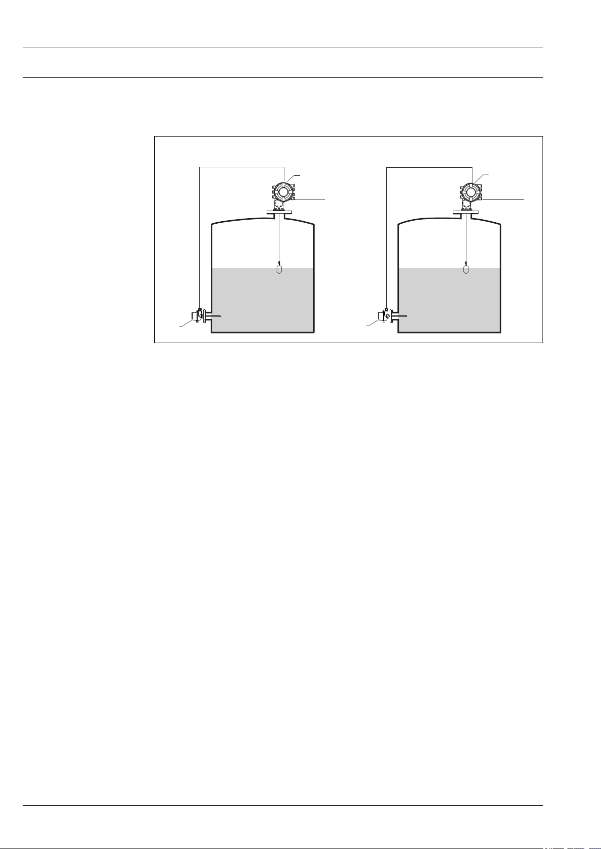
Measuring mode Installation example Measured variables Calculated variables
Level only
1 NMS8x
2 To inventory management system
Level + temperature
Level None
A0026912
• Level
• Temperature (point or average)
None
A0026913
1 NMS8x
2 To inventory management system
3 Temperature transmitter (point or average)
46 Endress+Hauser
Page 47

Proservo NMS83
2
3
D1
1
2
3
4 1
D3
HTMS measuring modes
Measuring mode Installation example Measured variables Calculated variables
HTMS + P1
This mode should be used in atmospheric (i.e.
non-pressurized) tanks
HTMS + P1 + P3
This mode should be used in non- atmospheric
(i.e. pressurized) tanks
Hybrid tank measurement system (HTMS)
HTMS uses level and pressure measurements to calculate the contents of the tank and (optionally)
the density of the medium.
• Level
• Bottom pressure (at position
D1)
A0026914
1 NMS8x
2 To inventory management system
3 Pressure transmitter (bottom)
• Level
• Bottom pressure (at position
D1)
• Top pressure (at position
D3)
Density of the
medium
Density of the
medium
A0026915
1 NMS8x
2 To inventory management system
3 Pressure transmitter (bottom)
4 Pressure transmitter (top)
Endress+Hauser 47
Page 48

Proservo NMS83
Δx
Hydrostatic tank shell correction (HyTD)
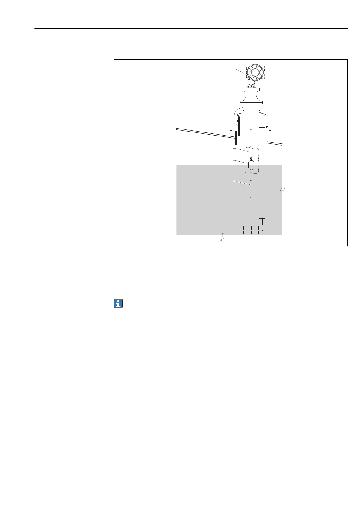
The hydrostatic tank shell correction can be used to compensate for vertical movement of the Gauge
Reference Height due to bulging of the tank shell caused by the hydrostatic pressure exerted by the
liquid stored in the tank. The compensation is based on a linear approximation obtained from
manual hand dips at several levels distributed over the full range of the tank.
A0026832
19 Movement Δx of the tank reference height due to the bulging of the tank shell caused by hydrostatic
pressure
Thermal tank shell correction (CTSh)
The thermal tank shell correction can be used to compensate for vertical movement of the Gauge
Reference Height due to temperature effects on the tank shell or stilling well. The calculation is
based on the thermal expansion coefficients of steel and on insulation factors for both the dry and
wetted part of the tank shell.
• This correction is recommended for any tank gauge operating at conditions deviating
considerably from the conditions during calibration and for extremely high tanks. For
refrigerated, cryogenic and heated applications this correction is highly recommended.
• Wire length can also be corrected with the parameters related to CTSh.
48 Endress+Hauser
Page 49

Proservo NMS83
32.5 (1.28)
319 (12.6)
471.6 (18.6)
Accessories
Device-specific accessories Weather protection cover
20 Weather protection cover; dimensions: mm (in)
Materials
Part Material
Protection cover and mounting brackets 316L (1.4404)
Screws and washers A4
• The weather protection cover can be ordered together with the device:
Ordering feature 620 "Accessory Enclosed", option PA "Weather Protection Cover")
• It can also be ordered as an accessory:
Order code: 71305035 (for NMS8x)
A0028872
Endress+Hauser 49
Page 50

Proservo NMS83
Calibration chamber
A calibration chamber is recommended for use with tank level gauges in order to allow maintenance
(removing the 70 mm (2.76 in) displacer or larger), while the tank is in service. Contact your Endress
+Hauser Sales Center if necessary.
Ball valve
Ball valves are recommended for use with tank level gauges in order to allow maintenance such as
removing displacers while tank is in service. Contact your Endress+Hauser Sales Center if necessary.
Control switch
A control switch is used for field mounted tank gauges. This provides additional gauge operation
contact switching in order to control the gauge’s operation, such as hoisting up the displacer. Contact
your Endress+Hauser Sales Center if necessary.
Relief valve and pressure gauge
A relief valve is used to release pressure inside the housing of NMS8x before maintenance.
21 Relief valve
A pressure gauge is used to check process pressure inside the housing.
22 Pressure gauge
A0028881
A0028882
50 Endress+Hauser
Page 51

Proservo NMS83
1
2
1
2
A0029104
23 Mounting position of relief valve and pressure gauge
1 Pressure gauge
2 Relief valve
Cleaning nozzle and gas purging nozzle
A cleaning nozzle used for washing inside housing is especially recommended for F&B or alcohol
applications.
A gas purging nozzle used for purging gas inside the housing is especially recommended for a
nitrogen blanket for petrochemical or chemical applications.
A0028884
24 Holes for cleaning nozzle and gas purging nozzle
1 Cleaning nozzle
2 Gas purging nozzle
Endress+Hauser 51
Page 52

Proservo NMS83
Communication-specific accessories
Service-specific accessories
Accessory Description
WirelessHART Adapter
SWA70
Accessory Description
Commubox FXA195
HART
Accessory Description
Commubox FXA291 Connects Endress+Hauser field devices with CDI interface (= Endress+Hauser
Accessory Description
FieldCare Endress+Hauser's FDT-based Plant Asset Management tool.
Connects field devices to a WirelessHART network.
The WirelessHART adapter can be mounted directly at a HART device and is easly
integrated into an existing HART network. It ensures safe data transmission and
can be operated in parallel with other wireless networks.
For details refer to Operating Instructions BA00061S
For intrinsically safe HART communication with FieldCare via the USB interface.
For details refer to Technical Information TI00404F
Common Data Interface) to the USB interface of a computer.
For details refer to Technical Information TI00405C
Helps to configure and maintain all field devices of your plant. By supplying status
information it also supports the diagnosis of the devices.
For details refer to Operating Instructions BA00027S and BA00059S.
System components
Accessory Description
RIA15 Compact process display unit with very low voltage drop for universal use to display
4 to 20 mA/HART signals
For details refer to Technical Information TI01043K.
Tankvision
• Tank Scanner NXA820
• Data Concentrator
NXA821
• Host Link NXA822
Inventory Management System with completely integrated software for operation
via standard web browser
For details refer to Technical Information TI00419G.
52 Endress+Hauser
Page 53

Proservo NMS83
Documentation
Technical Information (TI)
Brief Operating Instructions (KA)
Operating Instructions (BA)
Description of Device Parameters (GP)
The Technical Information contains all the technical data on the device and provides an overview of
the accessories and other products that can be ordered for the device.
Device Technical Information
Proservo NMS83 TI01250G
The Brief Operating Instructions contain all the essential information from incoming acceptance to
initial commissioning.
Device Brief Operating Instructions
Proservo NMS83 KA01206G
The Operating Instructions contain all the information that is required in various phases of the life
cycle of the device: from product identification, incoming acceptance and storage, to mounting,
connection, operation and commissioning through to troubleshooting, maintenance and disposal.
It also contains a detailed explanation of each individual parameter in the operating menu (except
the Expert menu). The description is aimed at those who work with the device over the entire life
cycle and perform specific configurations.
Device Operating Instructions
Proservo NMS83 BA01462G
The Description of Device Parameters provides a detailed explanation of each individual parameter in
the 2nd part of the operating menu: the Expert menu. It contains all the device parameters and
allows direct access to the parameters by entering a specific code. The description is aimed at those
who work with the device over the entire life cycle and perform specific configurations.
Device Description of Device Parameters
Proservo NMS83 GP01080G
Endress+Hauser 53
Page 54

Proservo NMS83
Safety instructions (XA)
Ordering feature 010 "Approval" Meaning XA
BC ATEX II 1/2G Ex db [ia Ga] IIC T6 Ga/Gb XA01495G
FD FM C/US XP-AIS Cl.I Div.1 Gr.BCD T6
AEx db [ia Ga] IIC T6 Ga/Gb
GC EAC Ga/Gb Ex db [ia Ga] IIC T6...T1 X XA01711G
IC IEC Ex db [ia Ga] IIC T6 Ga/Gb XA01495G
1)
KC
MC INMETRO Ex d[ia] IIC T6 Ga/Gb XA01705G
NC NEPSI Ex d[ia] IIC T6 Ga/Gb XA01704G
TC TIIS Ex d[ia] IIC T4 Ga/Gb XA01600G
1) KC approval is covered with IEC Ex approval.
KC Ex d[ia] IIC T6 Ga/Gb XA01495G
XA01496G
54 Endress+Hauser
Page 55

Proservo NMS83
Registered trademarks
FieldCare
Registered trademark of the Endress+Hauser Process Solutions AG, Reinach, Switzerland
MODBUS
Registered trademark of the MODBUS-IDA, Hopkinton, MA, USA
®
®
Endress+Hauser 55
Page 56

*71411299*
71411299
www.addresses.endress.com
 Loading...