

Page 1

KA01272T/09/A2/02.18
71395764
Products Solutions Services
Brief Operating Instructions
iTHERM TrustSens TM371, TM372
Compact thermometer with self-calibration
function
These instructions are brief operating instructions; they are
not a substitute for the operating instructions pertaining to
the device.
For detailed information, refer to the operating instructions
and other documentation.
Available for all device versions via:
• Internet: www.endress.com/deviceviewer
• Smartphone/Tablet: Endress+Hauser Operations App
Page 2

iTHERM TrustSens TM371, TM372
Order code:
Ext. ord. cd.:
Ser. no.:
www.endress.com/deviceviewer
Endress+Hauser
Operations App
XXXXXXXXXXXX
XXXXX-XXXXXX
XXX.XXXX.XX
Serial number
1.
3.
2.
2 Endress+Hauser
A0023555
Page 3

iTHERM TrustSens TM371, TM372
iTHERM TrustSens TM371, TM372
Compact thermometer with self-calibration function
Kurzanleitung ......................................................................... 4
Brief Operating Instructions .......................................................... 21
Endress+Hauser 3
Page 4

Inhaltsverzeichnis iTHERM TrustSens TM371, TM372
GEFAHR
WARNUNG
Inhaltsverzeichnis
1 Über dieses Dokument ............................................................ 4
1.1 Symbole ............................................................................. 4
2 Grundlegende Sicherheitshinweise ...............................................
2.1 Anforderungen an das Personal ............................................................ 6
2.2 Bestimmungsgemäße Verwendung ......................................................... 6
2.3 Betriebssicherheit ...................................................................... 6
2.4 Produktsicherheit ...................................................................... 6
3 Warenannahme und Produktidentifikation ....................................... 7
3.1 Warenannahme ....................................................................... 7
3.2 Produktidentifizierung .................................................................. 8
3.3 Transport und Lagerung ................................................................. 9
4 Montage ........................................................................ 10
4.1 Montagebedingungen .................................................................. 10
4.2 Messgerät montieren .................................................................. 10
4.3 Einbaukontrolle ...................................................................... 16
5 Elektrischer Anschluss .......................................................... 16
5.1 Anschlussbedingungen ................................................................. 16
5.2 Gerät anschließen ..................................................................... 16
5.3 Schutzart sicherstellen ................................................................. 17
5.4 Anschlusskontrolle .................................................................... 17
6 Bedienungsmöglichkeiten ....................................................... 18
6.1 Übersicht zu Bedienungsmöglichkeiten ..................................................... 18
6.2
Konfiguration Transmitter und HART®-Protokoll .............................................. 19
7 Inbetriebnahme ................................................................. 19
7.1 Funktionskontrolle .................................................................... 19
7.2 Messgerät einschalten ................................................................. 19
6
1 Über dieses Dokument
1.1 Symbole
1.1.1 Warnhinweissymbole
Symbol Bedeutung
GEFAHR!
Dieser Hinweis macht auf eine gefährliche Situation aufmerksam, die, wenn sie nicht
vermieden wird, zu Tod oder schwerer Körperverletzung führen wird.
WARNUNG!
Dieser Hinweis macht auf eine gefährliche Situation aufmerksam, die, wenn sie nicht
vermieden wird, zu Tod oder schwerer Körperverletzung führen kann.
4 Endress+Hauser
Page 5

iTHERM TrustSens TM371, TM372 Über dieses Dokument
VORSICHT
HINWEIS
,…,
Symbol Bedeutung
VORSICHT!
Dieser Hinweis macht auf eine gefährliche Situation aufmerksam, die, wenn sie nicht
vermieden wird, zu leichter oder mittelschwerer Körperverletzung führen kann.
HINWEIS!
Dieser Hinweis enthält Informationen zu Vorgehensweisen und weiterführenden
Sachverhalten, die keine Körperverletzung nach sich ziehen.
1.1.2 Elektrische Symbole
Symbol Bedeutung Symbol Bedeutung
Gleichstrom Wechselstrom
Gleich- und Wechselstrom Erdanschluss
Schutzleiteranschluss
Eine Klemme, die geerdet werden
muss, bevor andere Anschlüsse
hergestellt werden dürfen.
1.1.3 Symbole für Informationstypen
Symbol Bedeutung Symbol Bedeutung
Erlaubt
Abläufe, Prozesse oder Handlungen,
die erlaubt sind.
Verboten
Abläufe, Prozesse oder Handlungen,
die verboten sind.
Verweis auf Dokumentation Verweis auf Seite
Verweis auf Abbildung
Ergebnis eines Handlungsschritts Sichtkontrolle
Eine geerdete Klemme, die vom
Gesichtspunkt des Benutzers über ein
Erdungssystem geerdet ist.
Äquipotenzialanschluss
Ein Anschluss, der mit dem
Erdungssystem der Anlage verbunden
werden muss: Dies kann z.B. eine
Potenzialausgleichsleitung oder ein
sternförmiges Erdungssystem sein, je
nach nationaler bzw. Firmenpraxis.
Zu bevorzugen
Abläufe, Prozesse oder Handlungen,
die zu bevorzugen sind.
Tipp
Kennzeichnet zusätzliche
Informationen.
Handlungsschritte
Endress+Hauser 5
Page 6

Grundlegende Sicherheitshinweise iTHERM TrustSens TM371, TM372
1.1.4 Werkzeugsymbole
Symbol Bedeutung
Gabelschlüssel
A0011222
2 Grundlegende Sicherheitshinweise
2.1 Anforderungen an das Personal
Das Personal muss für seine Tätigkeiten folgende Bedingungen erfüllen:
Ausgebildetes Fachpersonal: Verfügt über Qualifikation, die dieser Funktion und Tätigkeit
‣
entspricht.
Vom Anlagenbetreiber autorisiert.
‣
Mit den nationalen Vorschriften vertraut.
‣
Vor Arbeitsbeginn: Anweisungen in Anleitung und Zusatzdokumentation sowie Zertifikate
‣
(je nach Anwendung) lesen und verstehen.
Anweisungen und Rahmenbedingungen befolgen.
‣
2.2 Bestimmungsgemäße Verwendung
• Das Gerät ist ein Kompaktthermometer zur Erfassung und Umformung von
Temperatureingangssignalen für die industrielle Temperaturmessung.
• Der Hersteller haftet nicht für Schäden, die aus unsachgemäßer oder nicht
bestimmungsgemäßer Verwendung entstehen.
2.3 Betriebssicherheit
HINWEIS
Betriebssicherheit
Betreiben Sie das Gerät nur in einwandfreiem und sicherem Zustand.
‣
Der Bediener ist für einen störungsfreien Betrieb des Gerätes verantwortlich.
‣
Reparatur
Das Gerät kann auf Grund seiner Bauform nicht repariert werden.
Es ist jedoch möglich, das Gerät für eine Überprüfung einzusenden.
‣
Nur Original-Ersatzteile und Zubehör von Endress+Hauser verwenden, um kontinuierliche
‣
Betriebssicherheit und Zuverlässigkeit sicherzustellen.
2.4 Produktsicherheit
Dieses Messgerät ist nach dem Stand der Technik und guter Ingenieurspraxis betriebssicher
gebaut und geprüft und hat das Werk in sicherheitstechnisch einwandfreiem Zustand
verlassen.
6 Endress+Hauser
Page 7
iTHERM TrustSens TM371, TM372 Warenannahme und Produktidentifikation
DELIVERYNOTE
Es erfüllt die allgemeinen Sicherheitsanforderungen und gesetzlichen Anforderungen. Zudem
ist es konform zu den EG-Richtlinien, die in der gerätespezifischen EG-Konformitätserklärung
aufgelistet sind. Mit der Anbringung des CE-Zeichens bestätigt Endress+Hauser diesen
Sachverhalt.
3
3.1
Warenannahme und Produktidentifikation
Warenannahme
1. Gerät vorsichtig auspacken. Sind Verpackung oder Inhalt unbeschädigt?
Beschädigte Komponenten dürfen nicht installiert werden, da der Hersteller
andernfalls die Einhaltung der ursprünglichen Sicherheitsanforderungen oder die
Materialbeständigkeit nicht gewährleisten und daher auch nicht für daraus
entstehende Schäden verantwortlich gemacht werden kann.
2. Ist die gelieferte Ware vollständig? Vergleichen Sie den Lieferumfang mit Ihren
Bestellangaben.
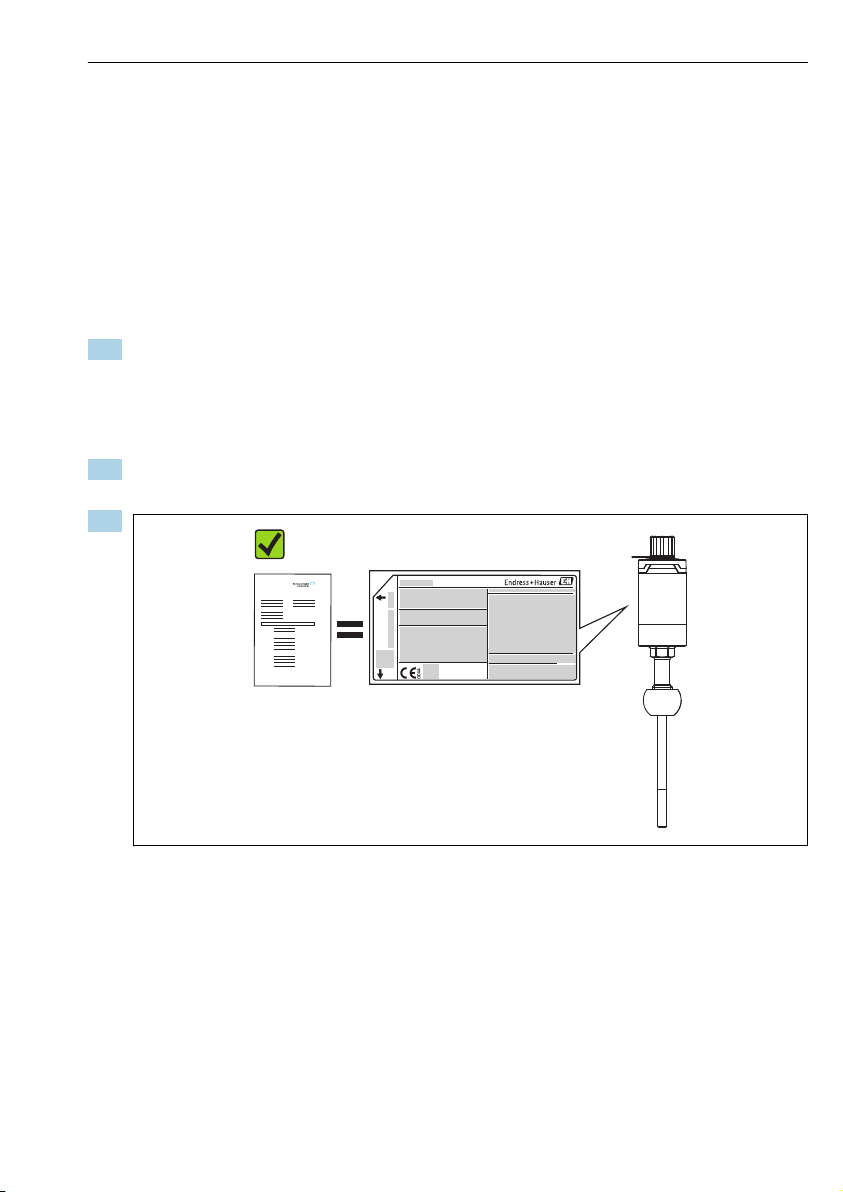
3.
Entsprechen die Typenschilddaten den Bestellangaben auf dem Lieferschein?
Endress+Hauser 7
A0028503
Page 8

Warenannahme und Produktidentifikation iTHERM TrustSens TM371, TM372
TMT162
TrustSens
TM371, 372
Input:
1
2
3
4
5
6
4.
A0028522
Sind die Technische Dokumentation und alle weiteren erforderlichen Dokumente, z. B.
Zertifikate vorhanden?
Wenn eine der Bedingungen nicht erfüllt ist: Wenden Sie sich an Ihre Endress+Hauser
Vertriebsstelle.
3.2 Produktidentifizierung
Folgende Möglichkeiten stehen zur Identifizierung des Gerätes zur Verfügung:
Typenschildangaben
•
• Seriennummer vom Typenschild in W@M Device Viewer eingeben (www.endress.com/
deviceviewer): Alle Angaben zum Gerät und eine Übersicht zum Umfang der mitgelieferten
Technischen Dokumentation werden angezeigt.
3.2.1 Typenschild
Das richtige Gerät?
Vergleichen und prüfen Sie die Angaben auf dem Typenschild des Gerätes mit den
Anforderungen der Messstelle:
1
Bestellcode, Seriennummer
2 Messstellenbezeichnung
3 Versorgungsspannung und Stromaufnahme
4 Geräterevision und Firmware-Version
5 Umgebungstemperatur
6 Zulassungen mit Symbolen
1 Typenschild des Kompaktthermometers
8 Endress+Hauser
(Beispiel)
A0033853
Page 9

iTHERM TrustSens TM371, TM372 Warenannahme und Produktidentifikation
3.2.2 Lieferumfang
Im Lieferumfang sind enthalten:
•
Kompaktthermometer
Gedruckte, mehrsprachige Kurzanleitung
•
• Bestelltes Zubehör
3.2.3 Zertifikate und Zulassungen
Eine Übersicht über weitere verfügbare Zulassungen und Zertifikate finden Sie im Kapitel
"Technische Daten" in der entsprechenden Betriebsanleitung.
CE-/EAC-Kennzeichen, Konformitätserklärung
Das Gerät erfüllt die gesetzlichen Anforderungen der EU-/EEU-Richtlinien. Der Hersteller
bestätigt die Einhaltung der entsprechenden Richtlinien mit der Anbringung des CE-/EACKennzeichens.
Hygiene-Standard
•
EHEDG-Zertifizierung Typ EL - KLASSE I. Zulässige Prozessanschlüsse gemäß EHEDG, siehe
entsprechende Betriebsanleitung.
3-A Autorisierungs-Nr. 1144, 3-A Sanitary Standard 74-06. Zulässige Prozessanschlüsse
•
gemäß 3-A, siehe entsprechende Betriebsanleitung.
• ASME BPE, Konformitätszertifikat bestellbar für ausgewiesene Optionen
• FDA-konform
• Tierfettfreie Produktion aller mediumsberührenden Oberflächen (TSE-konform)
Mediumsberührende Teile
Die mediumsberührenden Teile des Thermometers entsprechen folgenden europäischen
Verordnungen:
• (EC) Nr. 1935/2004, Art. 3, Absatz 1, Art. 5 und 17 über Materialien und Gegenstände, die
dazu bestimmt sind, mit Lebensmitteln in Berührung zu kommen.
• (EC) Nr. 2023/2006 über die gute Herstellungspraxis (Good Manufacturing Practice, GMP)
für Materialien und Gegenstände, die dazu bestimmt sind, mit Lebensmitteln in Berührung
zu kommen.
• (EU) Nr. 10/2011 über Materialien und Gegenstände aus Kunststoff, die dazu bestimmt
sind, mit Lebensmitteln in Berührung zu kommen.
3.3 Transport und Lagerung
Das Gerät so verpacken, dass es bei Lagerung (und Transport) zuverlässig vor Stößen
geschützt wird. Die Originalverpackung bietet optimalen Schutz.
Lagertemperatur –40 … +85 °C (–40 … +185 °F)
Endress+Hauser 9
Page 10

Montage iTHERM TrustSens TM371, TM372
4 Montage
4.1 Montagebedingungen
Die Eintauchlänge des Thermometers kann sich auf die Messgenauigkeit auswirken. Bei zu
geringer Eintauchlänge kann es durch die Wärmeableitung über den Prozessanschluss
kommen. Daher empfiehlt sich beim Einbau in ein Rohr eine Eintauchlänge, die idealerweise
der Hälfte des Rohrdurchmessers entspricht.
• Einbaumöglichkeiten: Rohre, Tanks oder andere Anlagenkomponenten
• Einbaulage: keine Einschränkungen . Allerdings muss die Selbstentleerung im Prozess
gewährleistet sein. Falls eine Öffnung zur Leckageerkennung am Prozessanschluss
vorhanden ist, muss diese am tiefsten Punkt liegen.
4.1.1 Umgebungstemperaturbereich
Umgebungstemperatur Ta–40 … +60 °C (–40 … +140 °F)
Max. Gerätetemperatur T –40 … +85 °C (–40 … +185 °F)
4.1.2 Klimaklasse
Nach IEC 60654-1, Klasse Dx
4.1.3 Schutzart
IP67/68 für Gehäuse mit LED-Statusanzeige
•
• IP69K für Gehäuse ohne LED-Statusanzeige und mit Anschlusskabel mit M12x1Verschraubung
→ 10
4.1.4 Stoß- und Schwingungsfestigkeit
Die Temperaturfühler von Endress+Hauser erfüllen die Anforderungen der IEC 60751, die
eine Stoß- und Schwingungsfestigkeit von 3g im Bereich von 10...500 Hz fordert. Dies gilt
auch für den Schnellverschluss iTHERM QuickNeck.
4.1.5 Elektromagnetische Verträglichkeit (EMV)
EMV gemäß allen relevanten Anforderungen der IEC/EN 61326-Serie und NAMUREmpfehlung EMV (NE21). Details sind aus der Konformitätserklärung ersichtlich. Alle
Prüfungen wurden sowohl mit als auch ohne laufende digitale HART®-Kommunikation
bestanden.
Alle EMV-Messungen wurden mit einem Turndown (TD) = 5:1 vorgenommen. Maximale
Schwankungen während der EMV-Tests: < 1 % der Messspanne.
Störfestigkeit nach IEC/EN 61326-Serie, Anforderungen für industrielle Bereiche.
Störaussendung nach IEC/EN 61326-Serie, Betriebsmittel der Klasse B.
4.2 Messgerät montieren
Erforderliche Werkzeuge für die Montage in einem vorhandenen Schutzrohr: Gabel- oder
Steckschlüssel SW/AF 32
10 Endress+Hauser
Page 11

iTHERM TrustSens TM371, TM372 Montage
SW/AF 32
SW/AF 17
1
2
3
4
A0028639
2
Montage des Kompaktthermometers
1 Montage des iTHERM QuickNeck-Anschlusses am vorhandenen Schutzrohr mit iTHERM QuickNeck-
Bodenteil - keine Werkzeuge erforderlich
2 Hexagonaler Kopf SW/AF 32 zur Montage in einem vorhandenen Schutzrohr für M24-, G3/8"-
Gewinde
3 Anpassbare Klemmverschraubung TK40 - Montage der hexagonalen Schraube nur mit Gabelschlüssel
SW/AF 17
4 Schutzrohr
Endress+Hauser 11
Page 12

Montage iTHERM TrustSens TM371, TM372
1
2
3
4
5
M
M
M
Maximales Drehmoment
A0035951
Schutzrohrversion TT411, 6 mm (0,24 in) (1)
Drehmoment M 3 … 5 Nm (2,2 … 3,7 lbf ft) 10 Nm (7,4 lbf ft) 3 … 5 Nm (2,2 … 3,7 lbf ft)
6
TT411,
Halsrohr TE411 (2)
mm (0,24 in) und
TT411, 9 mm (0,35 in)
(3)
TT411, 12,7 mm (¹⁄₂ in) (4)
TT411, 12,7 mm (¹⁄₂ in) und
Halsrohr TE411 (5)
Wenn das Gerät mit dem Schutzrohr verbunden wird: nur an den hexagonalen
Schlüsselflächen am unteren Gehäuserand festziehen.
12 Endress+Hauser
Page 13

iTHERM TrustSens TM371, TM372 Montage
U
≥ 3°
≥ 3°
1
2
3
4
A0031007
3
Montagemöglichkeiten im Prozess
1, 2 Senkrecht zur Strömungsrichtung, Einbau mit min. 3° Neigung, um Selbstentleerung zu gewährleisten
3 An Winkelstücken
4 Schräger Einbau in Rohren mit kleinem Nenndurchmesser
U Eintauchlänge
Bei Rohren mit kleinen Nenndurchmessern empfiehlt es sich, dass die Spitze des
Thermometers weit genug in den Prozess ragt, um über die Achse der Rohrleitung hinaus zu
reichen. Eine andere Lösung kann ein schräger Einbau sein (4). Bei der Bestimmung der
Eintauchlänge bzw. Einbautiefe müssen alle Parameter des Thermometers und des zu
messenden Mediums berücksichtigt werden (z. B. Durchflussgeschwindigkeit, Prozessdruck).
Endress+Hauser 13
Page 14

Montage iTHERM TrustSens TM371, TM372
1
2
A0031022
4
Prozessanschlüsse für Thermometerinstallation in Rohren mit kleinen Nenndurchmessern
1 Varivent® - Prozessanschluss Typ N für DN40
2 Eck- oder T-Stück (abgebildet) zum Einschweißen nach DIN 11865 / ASME BPE 2012
14 Endress+Hauser
Page 15

iTHERM TrustSens TM371, TM372 Montage
1 2
3 4
R0.4 R0.4
Sensor mit
Milchrohrverschraubung
Sensor mit
Varivent Anschluss
Formdichtung
Gegenanschluss
Gegenanschluss
O-Ring
Nutüberwurfmutter
Gegenanschluss
Zentrierring
Dichtungsring
Formdichtung
(O-Ring)
Einschweißadapter
Öffnung zur
Leckageerkennung
Behälterwand
5
1 Milchrohrverschraubung nach DIN 11851, nur in Verbindung mit EHEDG bescheinigtem und
2 Varivent® - Prozessanschluss für VARINLINE®-Gehäuse
3 Clamp nach ISO 2852
4 Liquiphant-M-Prozessanschluss G1", horizontaler Einbau
Die Gegenstücke für die Prozessanschlüsse sowie die Dichtungen oder Dichtringe sind nicht im
Lieferumfang des Thermometers enthalten. Liquiphant-M-Einschweißadapter mit
zugehörigen Dichtungskits sind als Zubehör erhältlich, siehe entsprechende
Betriebsanleitungen
Endress+Hauser 15
Detaillierte Einbauhinweise bei hygienegerechter Installation
selbstzentrierenden Dichtring
.
A0028648-DE
Page 16

Elektrischer Anschluss iTHERM TrustSens TM371, TM372
Vorgehensweise, falls ein Anschluss zur Leckageerkennung den Ausfall einer Dichtung
anzeigt:
1. Demontage des Thermometers, validierter Reinigungsprozess für Gewinde und
Dichtringnut
2. Austausch der Dichtung oder des Dichtungsrings
3. CIP nach Wiedermontage
Bei eingeschweißten Anschlüssen müssen die Schweißarbeiten auf der Prozessseite mit der
erforderlichen Sorgfalt durchgeführt werden:
•
Geeigneter Schweißwerkstoff
Bündig geschweißt oder mit Schweißradius > 3,2 mm (0,13 in)
•
• Keine Vertiefungen, Falten, Spalten
• Geschliffene und polierte Oberfläche, Ra ≤ 0,76 µm (0,03 µin)
Die Thermometer sind generell so einzubauen, dass ihre Reinigungsfähigkeit nicht
beeinträchtigt wird (Anforderungen nach Standard 3-A müssen eingehalten werden).
Die Anschlüsse Varivent®, Liquiphant-M-Einschweißadapter und Ingold (+
Einschweißadapter) ermöglichen eine frontbündige Montage.
4.3
Ist das Gerät geeignet fixiert?
Entspricht das Gerät den Messstellenspezifikationen, wie z. B. Umgebungstemperatur, Messbereich usw.?
Einbaukontrolle
Ist das Gerät unbeschädigt (Sichtprüfung)?
5 Elektrischer Anschluss
5.1 Anschlussbedingungen
Elektrische Anschlussleitungen müssen nach 3-A Standard glatt, korrosionsbeständig
und einfach zu reinigen sein.
5.2 Gerät anschließen
HINWEIS
Um eine Beschädigung des Gerätes zu vermeiden
Zum Schutz der Geräteelektronik vor Beschädigungen die Kontakte 2 und 4 nicht
‣
anschließen. Sie sind für den Anschluss des Konfigurationskabels reserviert.
M12-Stecker nicht zu fest anziehen, um eine Beschädigung des Gerätes zu vermeiden.
‣
16 Endress+Hauser
Page 17

iTHERM TrustSens TM371, TM372 Elektrischer Anschluss
M12x1
1
12...30 VDC
(4...20 mA)
3
0 V
(4...20 mA)
4
2
A
B
1 (BN) +
2 (WH) nc
3 (BU) -
4 (BK) nc
1.
2.
6
Kabelstecker M12x1 und Steckerbelegung des Anschlusssockels am Gerät
Wenn die Spannungsversorgung korrekt angeschlossen wurde und das Messgerät
betriebsbereit ist, leuchtet die LED grün.
5.3 Schutzart sicherstellen
Die angegebene Schutzart ist gewährleistet, wenn der M12x1 Kabelstecker festgezogen ist.
Für die Einhaltung der Schutzart IP69K sind entsprechende Geräteanschlussleitungen mit
geraden oder gewinkelten Steckern verfügbar.
5.4 Anschlusskontrolle
Sind Gerät und Kabel unbeschädigt (Sichtkontrolle)?
Verfügen die montierten Kabel über eine geeignete Zugentlastung?
Stimmt die Versorgungsspannung mit den Angaben auf dem Typenschild überein?
Endress+Hauser 17
A0028623
Page 18

Bedienungsmöglichkeiten iTHERM TrustSens TM371, TM372
2 3
1
4 5
6 Bedienungsmöglichkeiten
6.1 Übersicht zu Bedienungsmöglichkeiten
A0031089
7 Bedienungsmöglichkeiten des Gerätes
1
Installiertes iTHERM-Kompaktthermometer mit HART®-Kommunikationsprotokoll
2 2-Leiter-Prozessanzeiger RIA15 - Der Prozessanzeiger wird in die Stromschleife eingebunden und
zeigt das Messsignal oder die HART®-Prozessvariablen in digitaler Form an. Der Prozessanzeiger
erfordert keine externe Spannungsversorgung. Er wird direkt über die Stromschleife gespeist.
3
Speisetrenner RN221N - Der Speisetrenner RN221N (24 V DC, 30 mA) verfügt über einen galvanisch
getrennten Ausgang zur Spannungsversorgung von 2-Leiter-Messumformern. Das
Weitbereichsnetzteil arbeitet mit einer Netzspannung am Eingang von 20 bis 250 V DC/AC, 50/60
Hz, sodass der Einsatz in allen internationalen Netzen möglich ist.
4 Commubox FXA195 für die eigensichere HART®-Kommunikation mit FieldCare über die USB-
Schnittstelle.
5 FieldCare ist ein FDT-basiertes Plant Asset Management Tool von Endress+Hauser, nähere
Informationen hierzu unter "Zubehör". Die erfassten Selbstkalibrierdaten werden im Gerät (1)
gespeichert und können mithilfe von FieldCare gelesen werden. Dadurch besteht auch die Möglichkeit,
einen auditierbaren Kalibrierschein zu erstellen und auszudrucken.
18 Endress+Hauser
Page 19

iTHERM TrustSens TM371, TM372 Inbetriebnahme
6.2
Konfiguration Transmitter und HART®-Protokoll
Das Kompaktthermometer wird über das HART®-Protokoll oder die CDI (= Endress+Hauser
Common Data Interface)-Schnittstelle konfiguriert. Dafür stehen folgende Bedientools zur
Verfügung:
Bedientools
FieldCare, DeviceCare, Field Xpert
(Endress+Hauser)
AMS Device Manager
(Emerson Process Management)
SIMATIC PDM
(Siemens)
Field Communicator 375, 475
(Emerson Process Management)
In der entsprechenden Betriebsanleitung ist die Konfiguration gerätespezifischer
Parameter ausführlich beschrieben.
7 Inbetriebnahme
7.1
Vergewissern Sie sich, dass alle Abschlusskontrollen durchgeführt wurden, bevor Sie Ihr Gerät
in Betrieb nehmen:
• Checkliste “Einbaukontrolle”→ 16
• Checkliste "Anschlusskontrolle" → 17
Funktionskontrolle
7.2 Messgerät einschalten
Falls Sie die Abschlusskontrollen durchgeführt haben, schalten Sie nun die
Versorgungsspannung ein. Nach dem Einschalten durchläuft das Gerät interne
Testfunktionen. Dies wird durch eine rot blinkende LED angezeigt. Nach etwas 10 s ist das
Gerät betriebsbereit und befindet sich in der normalen Betriebsart. Die LED auf dem Gerät
leuchtet grün.
Endress+Hauser 19
Page 20

Inbetriebnahme iTHERM TrustSens TM371, TM372
1
7.2.1 Anzeigeelemente
Position LEDs Funktionsbeschreibung
LED-Signale zeigen
1
verschiedene Funktionen an
Grüne LED (gn)
leuchtet
Grüne LED (gn) blinkt
Rote LED (rd) und grüne LED
(gn) blinken abwechselnd
Rote LED (rd) blinkt Mit einer Frequenz von 1 Hz: Signalisiert ein
A0031589
Rote LED (rd) leuchtet Signalisiert ein Diagnoseereignis (Alarm).
Spannungsversorgung ist in Ordnung. Das
Messgerät ist betriebsbereit und die
festgelegten Grenzwerte werden eingehalten.
Mit einer Frequenz von 1 Hz: Das Gerät
startet die Selbstkalibrierung, bis die
Erkennung beendet wird.
Mit einer Frequenz von 5 Hz während 5 s:
Status OK, Status Kalibrierpunkt OK erkannt.
Mit einer Frequenz von 5 Hz: Status OK,
Status Kalibrierpunkt SCHLECHT erkannt.
Diagnoseereignis (Warnung).
Das Gerät misst weiter. Für das
Überwachungssystem wird eine
Diagnosemeldung generiert.
Die Messung wird unterbrochen. Die
Signalausgänge nehmen den definierten
Alarmzustand an. Für das
Überwachungssystem wird eine
Diagnosemeldung generiert.
Nähere Informationen hierzu: siehe entsprechende Betriebsanleitung BA01581T.
20 Endress+Hauser
Page 21

iTHERM TrustSens TM371, TM372 Table of contents
DANGER
WARNING
Table of contents
1 About this document ............................................................ 21
1.1 Symbols ............................................................................ 21
2 Basic safety instructions ......................................................... 23
Requirements for personnel ............................................................. 23
2.1
2.2 Intended use ......................................................................... 23
2.3 Operation safety ...................................................................... 23
2.4 Product safety ........................................................................ 23
3 Incoming acceptance and product identification ................................. 24
3.1 Incoming acceptance ................................................................... 24
3.2 Product identification .................................................................. 25
3.3 Transport and storage .................................................................. 26
4 Mounting ....................................................................... 26
4.1 Mounting conditions ................................................................... 26
4.2 Mounting the measuring device ........................................................... 27
4.3 Post-mounting check .................................................................. 33
5 Electrical connection ............................................................ 33
5.1 Connecting requirements ............................................................... 33
5.2 Connecting the device .................................................................. 33
5.3 Ensuring the degree of protection ......................................................... 34
5.4 Post-connection check .................................................................. 34
6 Operating options ............................................................... 35
6.1 Overview of operation options ............................................................ 35
6.2
Configuration of transmitter and HART® protocol .............................................. 35
7 Commissioning .................................................................. 36
7.1 Function check ....................................................................... 36
7.2 Switching on the measuring device ........................................................ 36
1 About this document
1.1 Symbols
1.1.1 Safety symbols
Symbol Meaning
DANGER!
This symbol alerts you to a dangerous situation. Failure to avoid this situation will result in
serious or fatal injury.
WARNING!
This symbol alerts you to a dangerous situation. Failure to avoid this situation can result in
serious or fatal injury.
Endress+Hauser 21
Page 22

About this document iTHERM TrustSens TM371, TM372
CAUTION
NOTICE
,…,
Symbol Meaning
CAUTION!
This symbol alerts you to a dangerous situation. Failure to avoid this situation can result in
minor or medium injury.
NOTE!
This symbol contains information on procedures and other facts which do not result in personal
injury.
1.1.2 Electrical symbols
Symbol Meaning Symbol Meaning
Direct current Alternating current
Direct current and alternating current Ground connection
Protective ground connection
A terminal which must be connected to
ground prior to establishing any other
connections.
1.1.3 Symbols for certain types of information
Symbol Meaning Symbol Meaning
Permitted
Procedures, processes or actions that
are permitted.
Forbidden
Procedures, processes or actions that
are forbidden.
Reference to documentation Reference to page
Reference to graphic
Result of a step Visual inspection
A grounded terminal which, as far as
the operator is concerned, is grounded
via a grounding system.
Equipotential connection
A connection that has to be connected
to the plant grounding system: This
may be a potential equalization line or
a star grounding system depending on
national or company codes of practice.
Preferred
Procedures, processes or actions that
are preferred.
Tip
Indicates additional information.
Series of steps
22 Endress+Hauser
Page 23

iTHERM TrustSens TM371, TM372 Basic safety instructions
1.1.4 Tool symbols
Symbol Meaning
Open-ended wrench
A0011222
2 Basic safety instructions
2.1 Requirements for personnel
The personnel must fulfill the following requirements for its tasks:
Trained, qualified specialists must have a relevant qualification for this specific function
‣
and task.
Are authorized by the plant owner/operator.
‣
Are familiar with federal/national regulations.
‣
Before starting work, read and understand the instructions in the manual and
‣
supplementary documentation as well as the certificates (depending on the application).
Follow instructions and comply with basic conditions.
‣
2.2 Intended use
• The device is a compact thermometer for the acquisition and conversion of temperature
input signals for industrial temperature measurement.
• The manufacturer is not liable for damage caused by improper or non-intended use.
2.3 Operation safety
NOTICE
Operation safety
Operate the device in proper technical condition and fail-safe condition only.
‣
The operator is responsible for interference-free operation of the device.
‣
Repair
Due to its design, the device cannot be repaired.
However, it is possible to send the device in for examination.
‣
To ensure continued operational safety and reliability, use original spare parts and
‣
accessories from Endress+Hauser only.
2.4 Product safety
This measuring device is designed in accordance with good engineering practice to meet stateof-the-art safety requirements, has been tested, and left the factory in a condition in which it
is safe to operate.
Endress+Hauser 23
Page 24

Incoming acceptance and product identification iTHERM TrustSens TM371, TM372
DELIVERYNOTE
TMT162
TrustSens
TM371, 372
It meets general safety standards and legal requirements. It also complies with the EC
directives listed in the device-specific EC Declaration of Conformity. Endress+Hauser confirms
this by affixing the CE mark to the device.
3
3.1
Incoming acceptance and product identification
Incoming acceptance
1. Unpack the device carefully. Is the packaging or content damaged?
The damaged content must not be installed; in those conditions the manufacturer
cannot guarantee the original safety requirements or the material resistance and
cannot be considered as responsible for any consequent damages.
2. Is the delivery complete? Compare the scope of delivery against the information on your
order form.
3.
A0028503
Do the nameplate data match the ordering information on the delivery note?
4.
A0028522
Are the technical documentation and additional documents (e.g. certificates) present?
If one of the conditions does not comply, contact your Endress+Hauser distributor.
24 Endress+Hauser
Page 25

iTHERM TrustSens TM371, TM372 Incoming acceptance and product identification
Input:
1
2
3
4
5
6
3.2 Product identification
The following options are available for identification of the device:
• Nameplate specifications
•
Enter the serial number from the nameplate in the W@M Device Viewer
(www.endress.com/deviceviewer): All data relating to the device and an overview of the
Technical Documentation supplied with the device are displayed.
3.2.1 Nameplate Is this the correct device?
Compare and check the data on the nameplate of the device against the requirements of the
measuring point:
Order code, serial number
1
2 Device TAG name
3 Supply voltage and current consumption
4 Device revision and firmware version
5 Ambient temperature
6 Approvals with symbols
A0033853
1 Nameplate of the compact thermometer
(example)
3.2.2 Scope of delivery
The scope of delivery comprises:
• Compact thermometer
•
Hard copy of multi-language Brief Operating Instructions
• Ordered accessories
3.2.3 Certificates and approvals
An overview of further approvals and certifications is provided in the ’Technical data’
section of the Operating instructions accordingly.
Endress+Hauser 25
Page 26

Mounting iTHERM TrustSens TM371, TM372
CE/EAC mark, declaration of conformity
The device meets the legal requirements of the EU/EEU guidelines. The manufacturer
confirms that the device is compliant with the relevant guidelines by applying the CE/EAC
mark.
Hygiene standard
•
EHEDG certification, type EL - CLASS I. Permitted process connections in accordance with
EHEDG, see Operating instructions accordingly.
3-A authorization no. 1144, 3-A sanitary standard 74-06. Permitted process connections in
•
accordance with 3-A, see Operating instructions accordingly.
• ASME BPE, certificate of conformity can be ordered for indicated options
• FDA-compliant
• All product contact surfaces are produced without animal fats (TSE Certificate of Suitability)
Parts in contact with the medium
Parts of the thermometer in contact with the medium comply with the following European
regulations:
• (EC) No. 1935/2004, Article 3, paragraph 1, Articles 5 and 17 on materials and articles
intended to come into contact with food.
• (EC) No. 2023/2006 on good manufacturing practice for materials and articles intended to
come into contact with food.
• (EU) No. 10/2011 on plastic materials and articles intended to come into contact with food.
3.3 Transport and storage
Pack the device in such a way as to protect it reliably against impact for storage (and
transportation). The original packaging provides optimum protection.
Storage temperature –40 to +85 °C (–40 to +185 °F)
4 Mounting
4.1 Mounting conditions
The immersion length of the thermometer can influence the accuracy. If the immersion length
is too small then errors in the measurement are caused by heat conduction via the process
connection. If installing into a pipe then the immersion length should ideally be half of the
pipe diameter. → 27
• Installation possibilities: Pipes, tanks or other plant components
• Orientation: no restrictions. However, self-draining in the process must be guaranteed. If
there is an opening to detect leaks at the process connection, this opening must be at the
lowest possible point.
26 Endress+Hauser
Page 27

iTHERM TrustSens TM371, TM372 Mounting
4.1.1 Ambient temperature range
Ambient temperature T
Maximum device
temperature T
–40 to +60 °C (–40 to +140 °F)
a
–40 to +85 °C (–40 to +185 °F)
4.1.2 Climate class
As per IEC 60654-1, Class Dx
4.1.3 Degree of protection
IP67/68 for housing with LED status indication
•
• IP69K for housing without LED status indication and with connecting cable with M12x1
coupling
4.1.4 Shock and vibration resistance
Endress+Hauser temperature sensors meet the requirements of IEC 60751 which specify
shock and vibration resistance of 3g in the range from 10 to 500 Hz. This also applies for the
quick-fastening iTHERM QuickNeck.
4.1.5 Electromagnetic compatibility (EMC)
EMC to all relevant requirements of the IEC/EN 61326 - series and NAMUR Recommendation
EMC (NE21). For details, refer to the Declaration of Conformity. All tests were passed both
with and without ongoing digital HART® communication.
All EMC measurements were performed with a turn down (TD) = 5:1. Maximum fluctuations
during EMC- tests: < 1% of measuring span.
Interference immunity to IEC/EN 61326 - series, requirements for industrial areas.
Interference emission to IEC/EN 61326 - series, electrical equipment Class B.
4.2 Mounting the measuring device
Required tools for mounting in an existing protection tube: Open-end wrench or mounting
socket wrench SW/AF 32
Endress+Hauser 27
Page 28

Mounting iTHERM TrustSens TM371, TM372
SW/AF 32
SW/AF 17
1
2
3
4
A0028639
2
1 Mounting of iTHERM QuickNeck connection to the existing protection tube with iTHERM QuickNeck
2 Hexagonal head SW/AF 32 for the mounting in an existing protection tube for M24-, G3/8"-thread
3 Adjustable compression fitting TK40 - mounting of the hexagonal screw with open-end wrench
4 Protection tube
Mounting process of the compact thermometer
bottom part - no tools required
SW/AF 17 only
28 Endress+Hauser
Page 29

iTHERM TrustSens TM371, TM372 Mounting
U
≥ 3°
≥ 3°
1
2
3
4
A0031007
3
Mounting possibilities in the process
1, 2 Perpendicular to flow direction, installed at a min. angle of 3° to ensure self-draining
3 On elbows
4 Inclined installation in pipes with a small nominal diameter
U Immersion length
In the case of pipes with a small nominal diameter, it is advisable for the tip of the
thermometer to project well into the process so that it extends past the pipe axis. Installation
at an angle (4) could be another solution. When determining the immersion length or
Endress+Hauser 29
Page 30

Mounting iTHERM TrustSens TM371, TM372
1
2
3
4
5
M
M
M
installation depth all the parameters of the thermometer and of the medium to be measured
must be taken into account (e.g. flow velocity, process pressure).
Maximum torque
A0035951
Protection tube version TT411, 6 mm (0.24 in) (1)
TT411, 6 mm
Necktube TE411 (2)
Torque M 3 to 5 Nm (2.2 to 3.7 lbf ft) 10 Nm (7.4 lbf ft) 3 to 5 Nm (2.2 to 3.7 lbf ft)
(0.24 in)
TT411,
and
9 mm (0.35 in) (3)
TT411, 12.7 mm (¹⁄₂ in) (4)
TT411, 12.7 mm (¹⁄₂ in) and
Necktube TE411 (5)
When connecting the device with the protection tube: only turn the hexagonal spanner
flat on the bottom of the housing.
30 Endress+Hauser
Page 31

iTHERM TrustSens TM371, TM372 Mounting
1
2
A0031022
4
Process connections for thermometer installation in pipes with small nominal diameters
1 Varivent® process connection type N for DN40
2 Corner piece or T-piece (illustrated) for weld-in as per DIN 11865 / ASME BPE 2012
Endress+Hauser 31
Page 32

Mounting iTHERM TrustSens TM371, TM372
1 2
3 4
R0.4 R0.4
Sensor with
milk pipe
connection
Sensor Variventwith
connection
Shaped
gasket
Companion
connection
O-ring
Groove
slip-on nut
Centering ring
Sealing
Companion
connection
Companion
connection
Gasket
(O-ring)
Welding boss
Leak detection hole
Vessel wall
5
1 Sanitary connection according to DIN 11851, only in connection with EHEDG-certified and self-
2 Varivent® process connection for VARINLINE® housing
3 Clamp according to ISO 2852
4 Liquiphant-M G1" process connection, horizontal installation
Detailed installation instructions for hygiene-compliant installation
centering sealing ring
The counterpieces for the process connections and the seals or sealing rings are not included
in the scope of supply for the thermometer. Liquiphant M weld-in adapters with associated
seal kits are available as accessories
, see corresponding operating instructions .
Procedure in case of seal failure indicated by leak detection port:
1. Disassembling of the thermometer, validated cleaning procedure of thread and sealing
ring groove
32 Endress+Hauser
A0028648-EN
Page 33

iTHERM TrustSens TM371, TM372 Electrical connection
2. Replacement of the seal or sealing ring
3. CIP after re-assembly
In the case of weld-in connections, exercise the necessary degree of care when performing the
welding work on the process side:
•
Suitable welding material
Flush-welded or with welding radius > 3.2 mm (0.13 in)
•
• No recesses, folds or gaps
• Honed and polished surface, Ra ≤ 0.76 µm (0.03 µin)
As a general rule, the thermometers should be installed in such a way that does not
impact their ability to be cleaned (the requirements of the 3-A Standard must be
observed). The Varivent® and Liquiphant-M weld-in adapter and Ingold (+ weld-in
adapter) connections enable flush-mounted installation.
4.3
Is the device fixed appropriately?
Does the device comply to the measurement point specifications, such as ambient temperature, etc.?
Post-mounting check
Is the device undamaged (visual inspection)?
5 Electrical connection
5.1 Connecting requirements
According to the 3-A Standard electrical connecting cables must be smooth, corrosionresistant and easy to clean.
5.2
NOTICE
To prevent damage to the device
‣
‣
Connecting the device
To prevent any kind of damage from the device electronics, leave the pins 2 and 4
unconnected. They are reserved for the connection of the configuration cable.
Do not tighten the M12 plug too much, in order to prevent damage to the device.
Endress+Hauser 33
Page 34

Electrical connection iTHERM TrustSens TM371, TM372
M12x1
1
12...30 VDC
(4...20 mA)
3
0 V
(4...20 mA)
4
2
A
B
1 (BN) +
2 (WH) nc
3 (BU) -
4 (BK) nc
1.
2.
6
Cable plug M12x1 and PIN assignment of the connection socket at the device
A0028623
If voltage supply is connected correctly and the measuring device is operational, the LED is
illuminated green.
5.3 Ensuring the degree of protection
The specified degree of proctection is ensured when the M12x1 cable plug is tightened. In
order to reach IP69K degree of protection, appropriate cord sets with straight or angle plugs
are available as accessories.
5.4 Post-connection check
Is the device or cable undamaged (visual check)?
Do the cables have adequate strain relief?
Does the supply voltage match the specifications on the nameplate?
34 Endress+Hauser
Page 35

iTHERM TrustSens TM371, TM372 Operating options
2 3
1
4 5
6 Operating options
6.1 Overview of operation options
A0031089
7 Operating options of the device
1
Installed iTHERM compact thermometer with HART® communication protocol
2 RIA15 loop powered process display - It is integrated in the current loop and displays the measuring
signal or HART® process variables in digital form. The process display unit does not require an
external power supply. It is powered directly from the current loop.
3
Active barrier RN221N - The RN221N (24 V DC, 30 mA) active barrier has a galvanically isolated
output for supplying voltage to loop-powered transmitters. The universal power supply works with an
input supply voltage of 20 to 250 V DC/AC, 50/60 Hz, which means that it can be used in all
international power grids.
4 Commubox FXA195 for intrinsically safe HART® communication with FieldCare via the USB interface.
5 FieldCare is a FDT-based plant asset management tool from Endress+Hauser, more details see section
'accessories'. The acquired self-calibration data is stored in the device (1) and can be read using
FieldCare. This also enables an auditable calibration certificate to be created and printed.
6.2
Configuration of transmitter and HART® protocol
The compact thermometer is configured via the HART® protocol, CDI (= Endress+Hauser
Common Data Interface). The following operating tools are available for this purpose:
Operating tools
FieldCare, DeviceCare, Field Xpert
(Endress+Hauser)
AMS Device Manager
(Emerson Process Management)
SIMATIC PDM
(Siemens)
Field Communicator 375, 475
(Emerson Process Management)
The configuration of device-specific parameters is described in detail in the
corresponding Operating Instructions.
Endress+Hauser 35
Page 36

Commissioning iTHERM TrustSens TM371, TM372
1
7 Commissioning
7.1 Function check
Before commissioning the device make sure that all final checks have been carried out:
•
Checklist "Post-mounting check" , → 33
• Checklist "Post-connection check", → 34
7.2 Switching on the measuring device
Once the final checks have been successfully completed, it is time to switch on the supply
voltage. The device performs a number of internal test functions after power-up. This is
indicated by red LED-flashing. The device is operational after approx. 10 seconds in normal
operating mode. The LED on the device is illuminated green.
7.2.1 Display elements
Position LEDs Function description
LED signals indicate
1
different functions
LED green (gn)
is illuminated
LED green (gn) is flashing
LED red (rd) and green (gn)
are flashing alternating
LED red (rd) is flashing With a frequency 1 Hz: It signals a diagnostic
A0031589
LED red (rd) is illuminated It signals a diagnostic event (Alarm).
Voltage supply is correct. The measuring
device is operational and the set limit values
are met.
With a frequency 1 Hz: The device starts the
self-calibration until detection has ended.
With a frequency 5 Hz for 5 s: Status OK,
calibration point status OK detected.
With a frequency 5 Hz: Status OK, calibration
point status BAD detected.
event (Warning).
The device continues to measure. A
diagnostic message is generated for the
monitoring system.
Measurement is interrupted. The signal
outputs assume the defined alarm condition.
A diagnostic message is generated for the
monitoring system.
For detailed information, refer to the corresponding operation instructions BA01581T.
36 Endress+Hauser
Page 37

Page 38

Page 39

Page 40

www.addresses.endress.com
 Loading...